EP1929180B1 - Pulley assembly for a continuously variable transmission - Google Patents
Pulley assembly for a continuously variable transmissionDownload PDFInfo
- Publication number
- EP1929180B1 EP1929180B1EP05794577AEP05794577AEP1929180B1EP 1929180 B1EP1929180 B1EP 1929180B1EP 05794577 AEP05794577 AEP 05794577AEP 05794577 AEP05794577 AEP 05794577AEP 1929180 B1EP1929180 B1EP 1929180B1
- Authority
- EP
- European Patent Office
- Prior art keywords
- pulley
- pulley assembly
- cam
- support element
- shock
- Prior art date
- Legal status (The legal status is an assumption and is not a legal conclusion. Google has not performed a legal analysis and makes no representation as to the accuracy of the status listed.)
- Expired - Lifetime
Links
Images

Classifications
- F—MECHANICAL ENGINEERING; LIGHTING; HEATING; WEAPONS; BLASTING
- F16—ENGINEERING ELEMENTS AND UNITS; GENERAL MEASURES FOR PRODUCING AND MAINTAINING EFFECTIVE FUNCTIONING OF MACHINES OR INSTALLATIONS; THERMAL INSULATION IN GENERAL
- F16H—GEARING
- F16H61/00—Control functions within control units of change-speed- or reversing-gearings for conveying rotary motion ; Control of exclusively fluid gearing, friction gearing, gearings with endless flexible members or other particular types of gearing
- F16H61/66—Control functions within control units of change-speed- or reversing-gearings for conveying rotary motion ; Control of exclusively fluid gearing, friction gearing, gearings with endless flexible members or other particular types of gearing specially adapted for continuously variable gearings
- F—MECHANICAL ENGINEERING; LIGHTING; HEATING; WEAPONS; BLASTING
- F16—ENGINEERING ELEMENTS AND UNITS; GENERAL MEASURES FOR PRODUCING AND MAINTAINING EFFECTIVE FUNCTIONING OF MACHINES OR INSTALLATIONS; THERMAL INSULATION IN GENERAL
- F16H—GEARING
- F16H55/00—Elements with teeth or friction surfaces for conveying motion; Worms, pulleys or sheaves for gearing mechanisms
- F16H55/32—Friction members
- F16H55/52—Pulleys or friction discs of adjustable construction
- F16H55/56—Pulleys or friction discs of adjustable construction of which the bearing parts are relatively axially adjustable
- F—MECHANICAL ENGINEERING; LIGHTING; HEATING; WEAPONS; BLASTING
- F16—ENGINEERING ELEMENTS AND UNITS; GENERAL MEASURES FOR PRODUCING AND MAINTAINING EFFECTIVE FUNCTIONING OF MACHINES OR INSTALLATIONS; THERMAL INSULATION IN GENERAL
- F16H—GEARING
- F16H9/00—Gearings for conveying rotary motion with variable gear ratio, or for reversing rotary motion, by endless flexible members
- F16H9/02—Gearings for conveying rotary motion with variable gear ratio, or for reversing rotary motion, by endless flexible members without members having orbital motion
- F16H9/04—Gearings for conveying rotary motion with variable gear ratio, or for reversing rotary motion, by endless flexible members without members having orbital motion using belts, V-belts, or ropes
- F16H9/12—Gearings for conveying rotary motion with variable gear ratio, or for reversing rotary motion, by endless flexible members without members having orbital motion using belts, V-belts, or ropes engaging a pulley built-up out of relatively axially-adjustable parts in which the belt engages the opposite flanges of the pulley directly without interposed belt-supporting members
Definitions
- This inventionrelates to a pulley assembly for a continuously variable transmission, particularly for use on three- or four-wheeled vehicles and snowmobiles.
- a continuously variable transmissioncomprises a first pulley assembly connected to an internal combustion engine, namely the drive pulley assembly, a second pulley assembly connected to the wheels of the vehicle, namely the driven pulley assembly, and a belt wound between the two pulley assemblies.
- Each assemblyusually comprises a shaft connected to the motor and wheels, a support element driven by the shaft, and a pair of half-pulleys connected in a rotationally rigid way to the support and mobile in relation to one another along the swivelling support element to define the transmission ratio.
- the drive pulley assemblyincludes a clutch to couple the shaft selectively to the half-pulleys, and the driven pulley assembly is equipped with a cam device to control the relative axial.position between the pulleys.
- Pulley assemblies provided with cam devicesgenerally include a swivelling sleeve adapted to drive the wheels of the vehicle, a fixed half-pulley connected rigidly to the sleeve, a half-pulley which is axially mobile on the sleeve and driven in rotation by the cam device, and a spring to push the mobile half-pulley towards the fixed half-pulley.
- the mobile half-pulleyincludes a hub supported radially on the sleeve via a bushing, and a conical wall connected coaxially to the hub and adapted to cooperate with the drive belt.
- the cam devicecomprises a plurality of cams fitted to the sleeve which present a first and second profile converging on the mobile half-pulley, and a cam-follower portion carried by the hub of the mobile pulley which defines a plurality of circumferential cavities that house the corresponding cams with circumferential play.
- each cavityis defined laterally by two inclined sides which cooperate with the first or second profile respectively during a drive condition in which the engine drives the wheels, and during an engine-braking condition in which the wheels tend to drive the engine.
- the distance between the half-pulleys of the drive pulley assemblyis varied in a way dependent on speed, for example using a centrifugal control device; when the number of revolutions increases, the half-pulleys move closer together, thus increasing the winding diameter.
- the half-pulleys of the driven pulley assemblymove apart, compressing the spring, and the mobile half-pulley retracts, performing a partial rotation defined by the cam-follower portion which slides on the first profile of the corresponding cams.
- the sides of the cam-follower portioncooperate with the second profile, which is inclined so as to keep the half-pulleys of the driven pulley assembly close together in order to produce a transmission ratio that maximises the speed of the drive pulley assembly, and thus fully exploit the inertial braking action of the internal combustion engine.
- the closest prior art document US-B-6379274discloses a pulley assembly comprising a first and a second set of cam followers coupled to a first and a second set of cavities respectively.
- Each cam follower of the first and the second setcooperates with a single side of the respective cavity.
- each set of cam followersis biased on the relative side of the cavity in order to close any circumferential gap.
- the purpose of the present inventionis to provide a pulley assembly with a cam device able to avoid or at least reduce undesirable driving feel and noise using a principle which is alternative and simpler to that already disclosed in the prior art.
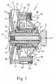
- No. 1 in figure 1indicates a pulley assembly for a continuously variable transmission.
- Assembly 1comprises a connecting shaft 2 swiveling around an axis A and having an end portion 3 adapted to be rigidly connected to a transmission element to drive a vehicle and a threaded portion 4 opposite to the end portion 3, a sleeve 6 rigidly connected to the shaft 2 via a bolt 8 screwed to the threaded portion 4 and housing the connecting shaft 2, a fixed half-pulley 9 rigidly connected to an end portion 10 of the sleeve 6, and a mobile half-pulley 11 radially supported by the sleeve 6.
- Fixed and mobile half-pulleys 9 and 11comprise conical walls 12 and 13 respectively and hubs 14 and 15 respectively, the first of which is keyed to the sleeve 6 and the second of which slides and swivels on a coupling 16 supported radially by the sleeve 6.
- Conical walls 12 and 13face one another and define a V-shaped groove 17 for a belt 18 which connects the pulley assembly 1 to a drive pulley assembly (not illustrated), directly driven by an internal combustion engine of the vehicle.
- the pulley assembly 1also includes a cup-shaped support 19 rigidly connected to the sleeve 6 on an axial part opposite to the fixed half-pulley 9, and an axial spring 20 interposed between the cup-shaped support 19 and the mobile half-pulley 11.
- the cup-shaped support 19comprises a hub 23 keyed to the sleeve 6 and a conical wall 24 converging from the side of hub 23 opposite the half-pulleys 9 and 11, and also defines a seating 25 radially positioned between the hub 23 and the conical wall 24 to house an end portion 26 of the axial spring 20.
- the axial spring 20is pre-loaded to push the mobile half-pulley 11 towards the fixed half-pulley 9, and axially stresses the cup-shaped support 19 which axially abuts against an elastic ring 27 which is carried by sleeve 6 and cooperates with the hub 23.
- the axial spring 20On the side axially opposite to end portion 26, the axial spring 20 has an end portion 28 which pre-loads a thrust bearing 29 against the mobile half-pulley 11.
- the thrust bearing 29presents a fifth wheel 30 which abuts against the conical wall 13, and a fifth wheel 31 which abuts against the axial spring 20 and is radially supported by the hub 15.
- the pulley assembly 1also includes a cam device 32 ( figs. 2-3 ) which presents a plurality of axial cam followers 35 supported peripherally on the conical wall 24, and a cam-follower portion that defines a plurality of cavities 33, which are carried circumferentially by a peripheral portion 34 of the conical wall 13 and house the corresponding axial cam followers 35.
- a cam device 32figs. 2-3
- the cam-follower portionthat defines a plurality of cavities 33, which are carried circumferentially by a peripheral portion 34 of the conical wall 13 and house the corresponding axial cam followers 35.
- each axial cam follower 35is connected via a screw 36 to a tooth 37 which exits radially from the conical wall 24 and comprises a cap 38 that defines a cavity 39 housing the tooth 37 and a shock-absorbing body 40, made of an elastomer material positioned inside the cavity 39 between the tooth 37 and the cap 38.
- the cap 38is made of polyamide, is preferably co-moulded onto the shock-absorbing body 40, and also defines a slot 41 that slidingly houses a shank of the screw 36.
- Each cap 38is constrained in the radial direction via the screw 36 to counteract the centrifugal acceleration action, and is enabled by the slot 41 to traverse in the circumferential direction in relation to the screw 36.
- the cavities 33 and the cam followers 35are surrounded in the radial direction by an external cylindrical wall 45 which is coaxial with axis A and exits from the conical wall 13 on the side opposite the V-shaped groove 17.
- the external cylindrical wall 45also supports a protective plate 46. inserted perpendicular to the axis A to close the cam follower 35 on the side opposite the cavities 33.
- the protective plate 46also has a circular edge 48 which is bent parallel to the axis A and faces an edge 49 that exits from the conical wall 24 on the side opposite the mobile half-pulley 11 to define a labyrinth seal and prevent debris and impurities from being deposited in the cavities 33 and on the cam follower 35.
- the cap 38also defines a first and a second contact surface 41, 42 which are transverse to the axis A and converge on the corresponding circumferential cavity 33 to cooperate with the corresponding sides 43, 44, which define each cavity 33 in the circumferential direction and converge on the fixed half-pulley 9.
- the pulley assembly 1is also provided with a ring 50 inserted in a seating 51 opposite the hub 14, defined on the hub 15 in a radially inner position with respect to the V-shaped groove 17.
- the ring 50is made of an anti-friction material and projects axially from the hub 15, forming a spacer to prevent direct contact between the hub 14 and the hub 15.
- the pulley assembly 1operates as follows.
- the pulley assembly 1When the internal combustion engine is switched off or idles, the pulley assembly 1 is in a closed position wherein the axial spring 20 keeps the half-pulleys 9, 11 together, defining a maximum reduction ratio suitable for pick-up.
- the pulley assembly 1is driven as a result of the friction component generated by the thrust of the axial spring 20 and by cam device 32.
- the sides 43 of the cavities 33are driven in abutment against the corresponding contact surfaces 41 and the shock-absorbing body 40 is deformed, allowing a substantially uniform distribution of the contact forces on each axial cam follower 35.
- the resultant of the contact forces between the caps 38 and the sides 43has an axial component which acts on the mobile half-pulley 11 and is directed towards the fixed half-pulley 9 to compress the belt 18.
- the resultant of the contact forcesalso has a circumferential component which acts on the cup-shaped support 19, driving the connecting shaft 2.
- the engine torqueis inverted and transmitted by the connecting shaft 2, which tends to accelerate compared with the belt 18.
- the fixed half-pulley 9remains rigidly connected with the sleeve 6, and the mobile half-pulley 11 tends to follow the belt 18 and slow down.
- the contact surface 41thus separates from the side 43, and on the opposite side, side 44 abuts against the contact surface 42, causing an .impact which is absorbed by the shock-absorbing body 40.
- the circumferential distance which separates the sides 43, 44 of a cavity 33 and the width of the axial cam followers 35are the same as those normally used when the cam means 32 are made with a reduced radius on the hub of the half-pulley.
- the circumferential play between the axial cam followers 35 and the cavities 33remains unchanged, but as it is positioned at a peripheral radial level, the angular movement travelled by the mobile pulley 11 without coming into contact with one of the sides 43, 44 during the transition from the forward drive condition to the engine-braking condition is reduced.
- the design of the cam means 32 with a peripheral diameterreduces the time for which the axial cam followers 35 and the sides 43, 44 are separated, thus improving the driving feel, particularly during transient states between the forward drive condition and the engine-braking condition.
- shock-absorbing bodies 40dissipates the energy of the impacts between the axial cam followers 35 and the sides 43, 44, thus increasing the quietness of the transmission during transient states.
- the shock-absorbing bodies 40better distribute the contact pressures, and increase the life of the axial cam followers 35.
- the pulley assembly 1could be provided with a clutch to selectively connect the shaft 2 to the sleeve 6.
- a shock-absorbing layercould also be laid on the sides 43, 44.
Landscapes
- Engineering & Computer Science (AREA)
- General Engineering & Computer Science (AREA)
- Mechanical Engineering (AREA)
- Transmissions By Endless Flexible Members (AREA)
- Pulleys (AREA)
Description
- This invention relates to a pulley assembly for a continuously variable transmission, particularly for use on three- or four-wheeled vehicles and snowmobiles.
- A continuously variable transmission comprises a first pulley assembly connected to an internal combustion engine, namely the drive pulley assembly, a second pulley assembly connected to the wheels of the vehicle, namely the driven pulley assembly, and a belt wound between the two pulley assemblies.
- Each assembly usually comprises a shaft connected to the motor and wheels, a support element driven by the shaft, and a pair of half-pulleys connected in a rotationally rigid way to the support and mobile in relation to one another along the swivelling support element to define the transmission ratio.
- In one possible embodiment, the drive pulley assembly includes a clutch to couple the shaft selectively to the half-pulleys, and the driven pulley assembly is equipped with a cam device to control the relative axial.position between the pulleys.
- Pulley assemblies provided with cam devices generally include a swivelling sleeve adapted to drive the wheels of the vehicle, a fixed half-pulley connected rigidly to the sleeve, a half-pulley which is axially mobile on the sleeve and driven in rotation by the cam device, and a spring to push the mobile half-pulley towards the fixed half-pulley. In particular, the mobile half-pulley includes a hub supported radially on the sleeve via a bushing, and a conical wall connected coaxially to the hub and adapted to cooperate with the drive belt.
- In known pulley assemblies, the cam device comprises a plurality of cams fitted to the sleeve which present a first and second profile converging on the mobile half-pulley, and a cam-follower portion carried by the hub of the mobile pulley which defines a plurality of circumferential cavities that house the corresponding cams with circumferential play. In particular, each cavity is defined laterally by two inclined sides which cooperate with the first or second profile respectively during a drive condition in which the engine drives the wheels, and during an engine-braking condition in which the wheels tend to drive the engine.
- During the drive condition, the distance between the half-pulleys of the drive pulley assembly is varied in a way dependent on speed, for example using a centrifugal control device; when the number of revolutions increases, the half-pulleys move closer together, thus increasing the winding diameter. As a result of the action of the belt, the half-pulleys of the driven pulley assembly move apart, compressing the spring, and the mobile half-pulley retracts, performing a partial rotation defined by the cam-follower portion which slides on the first profile of the corresponding cams.
- During the engine-braking condition, the sides of the cam-follower portion cooperate with the second profile, which is inclined so as to keep the half-pulleys of the driven pulley assembly close together in order to produce a transmission ratio that maximises the speed of the drive pulley assembly, and thus fully exploit the inertial braking action of the internal combustion engine.
- However, in known cam pulley assemblies, problems occur in the transition between the drive condition and the engine-braking condition. In particular, during the initial moments of the engine-braking condition, the cam-follower portion and the mobile half-pulley tend to oscillate circumferentially due to the play between the cams and cavities, and impact alternately on the opposite contact surfaces. Said oscillations generate an undesirable driving feel and noise, which make the comfort of the vehicle worse.
- The closest prior art document
US-B-6379274 discloses a pulley assembly comprising a first and a second set of cam followers coupled to a first and a second set of cavities respectively. Each cam follower of the first and the second set cooperates with a single side of the respective cavity. Furthermore, each set of cam followers is biased on the relative side of the cavity in order to close any circumferential gap. - The purpose of the present invention is to provide a pulley assembly with a cam device able to avoid or at least reduce undesirable driving feel and noise using a principle which is alternative and simpler to that already disclosed in the prior art.
- The purpose of this invention is achieved by means of a pulley assembly with a cam device as defined in claim 1.
- In order to explain the invention in greater detail, a preferred embodiment will now be described, by way of example but not of limitation, with reference to the annexed drawing wherein:
figure 1 is an axial cross-section of a pulley assembly according to the invention;figure 2 is a right-hand side view of a detail offigure 1 ; andfigure 3 is a cross-section along line III-III infigure 2 .- No. 1 in
figure 1 indicates a pulley assembly for a continuously variable transmission. - Assembly 1 comprises a connecting
shaft 2 swiveling around an axis A and having an end portion 3 adapted to be rigidly connected to a transmission element to drive a vehicle and a threaded portion 4 opposite to the end portion 3, a sleeve 6 rigidly connected to theshaft 2 via a bolt 8 screwed to the threaded portion 4 and housing the connectingshaft 2, a fixed half-pulley 9 rigidly connected to anend portion 10 of the sleeve 6, and a mobile half-pulley 11 radially supported by the sleeve 6.
Fixed and mobile half-pulleys 9 and 11 compriseconical walls hubs coupling 16 supported radially by the sleeve 6. Conical walls shaped groove 17 for abelt 18 which connects the pulley assembly 1 to a drive pulley assembly (not illustrated), directly driven by an internal combustion engine of the vehicle.- The pulley assembly 1 also includes a cup-
shaped support 19 rigidly connected to the sleeve 6 on an axial part opposite to the fixed half-pulley 9, and an axial spring 20 interposed between the cup-shaped support 19 and the mobile half-pulley 11. - In particular, the cup-
shaped support 19 comprises ahub 23 keyed to the sleeve 6 and aconical wall 24 converging from the side ofhub 23 opposite the half-pulleys 9 and 11, and also defines a seating 25 radially positioned between thehub 23 and theconical wall 24 to house anend portion 26 of the axial spring 20. - The axial spring 20 is pre-loaded to push the mobile half-
pulley 11 towards the fixed half-pulley 9, and axially stresses the cup-shaped support 19 which axially abuts against anelastic ring 27 which is carried by sleeve 6 and cooperates with thehub 23. - On the side axially opposite to
end portion 26, the axial spring 20 has anend portion 28 which pre-loads a thrust bearing 29 against the mobile half-pulley 11. - In particular, the thrust bearing 29 presents a
fifth wheel 30 which abuts against theconical wall 13, and afifth wheel 31 which abuts against the axial spring 20 and is radially supported by thehub 15. - To regulate the axial position of the mobile half-
pulley 11, allowing it to be driven, the pulley assembly 1 also includes a cam device 32 (figs. 2-3 ) which presents a plurality of axial cam followers 35 supported peripherally on theconical wall 24, and a cam-follower portion that defines a plurality ofcavities 33, which are carried circumferentially by aperipheral portion 34 of theconical wall 13 and house the corresponding axial cam followers 35. - In particular, each axial cam follower 35 is connected via a
screw 36 to atooth 37 which exits radially from theconical wall 24 and comprises acap 38 that defines acavity 39 housing thetooth 37 and a shock-absorbingbody 40, made of an elastomer material positioned inside thecavity 39 between thetooth 37 and thecap 38. - In particular, the
cap 38 is made of polyamide, is preferably co-moulded onto the shock-absorbingbody 40, and also defines aslot 41 that slidingly houses a shank of thescrew 36. Eachcap 38 is constrained in the radial direction via thescrew 36 to counteract the centrifugal acceleration action, and is enabled by theslot 41 to traverse in the circumferential direction in relation to thescrew 36. - The
cavities 33 and the cam followers 35 are surrounded in the radial direction by an externalcylindrical wall 45 which is coaxial with axis A and exits from theconical wall 13 on the side opposite the V-shaped groove 17. The externalcylindrical wall 45 also supports aprotective plate 46. inserted perpendicular to the axis A to close the cam follower 35 on the side opposite thecavities 33. - The
protective plate 46 also has acircular edge 48 which is bent parallel to the axis A and faces anedge 49 that exits from theconical wall 24 on the side opposite the mobile half-pulley 11 to define a labyrinth seal and prevent debris and impurities from being deposited in thecavities 33 and on the cam follower 35. - The
cap 38 also defines a first and asecond contact surface circumferential cavity 33 to cooperate with thecorresponding sides cavity 33 in the circumferential direction and converge on the fixed half-pulley 9. - The pulley assembly 1 is also provided with a
ring 50 inserted in aseating 51 opposite thehub 14, defined on thehub 15 in a radially inner position with respect to the V-shaped groove 17. Thering 50 is made of an anti-friction material and projects axially from thehub 15, forming a spacer to prevent direct contact between thehub 14 and thehub 15. - The pulley assembly 1 operates as follows.
- When the internal combustion engine is switched off or idles, the pulley assembly 1 is in a closed position wherein the axial spring 20 keeps the half-
pulleys 9, 11 together, defining a maximum reduction ratio suitable for pick-up. - During the drive condition, indicated by the arrow in
figure 3 , the pulley assembly 1 is driven as a result of the friction component generated by the thrust of the axial spring 20 and bycam device 32. In particular, thesides 43 of thecavities 33 are driven in abutment against thecorresponding contact surfaces 41 and the shock-absorbingbody 40 is deformed, allowing a substantially uniform distribution of the contact forces on each axial cam follower 35. - The resultant of the contact forces between the
caps 38 and thesides 43 has an axial component which acts on the mobile half-pulley 11 and is directed towards the fixed half-pulley 9 to compress thebelt 18. The resultant of the contact forces also has a circumferential component which acts on the cup-shaped support 19, driving the connectingshaft 2. - Following a variation in the transmission ratio due, for example, to acceleration, the winding diameter around the drive pulley assembly increases and the winding diameter around the driven pulley assembly decreases. Consequently, the mobile half-
pulley 11 retracts against the action of the spring 20 and performs a partial rotation guided by theside 43. - In the engine-braking condition, the engine torque is inverted and transmitted by the connecting
shaft 2, which tends to accelerate compared with thebelt 18. In this case, the fixed half-pulley 9 remains rigidly connected with the sleeve 6, and the mobile half-pulley 11 tends to follow thebelt 18 and slow down. Thecontact surface 41 thus separates from theside 43, and on the opposite side,side 44 abuts against thecontact surface 42, causing an .impact which is absorbed by the shock-absorbingbody 40. - In particular, the circumferential distance which separates the
sides cavity 33 and the width of the axial cam followers 35 are the same as those normally used when thecam means 32 are made with a reduced radius on the hub of the half-pulley. In this way, the circumferential play between the axial cam followers 35 and thecavities 33 remains unchanged, but as it is positioned at a peripheral radial level, the angular movement travelled by themobile pulley 11 without coming into contact with one of thesides
The advantages of the present pulley assembly 1 are as follows. - The design of the cam means 32 with a peripheral diameter reduces the time for which the axial cam followers 35 and the
sides - Moreover, the presence of shock-absorbing
bodies 40 dissipates the energy of the impacts between the axial cam followers 35 and thesides - During the driving condition, the shock-absorbing
bodies 40 better distribute the contact pressures, and increase the life of the axial cam followers 35. - Finally, any modifications and variations which may be made to the pulley assembly 1 described and illustrated here would obviously still fall within the scope of this invention, as defined in the attached claims.
- In particular, the pulley assembly 1 could be provided with a clutch to selectively connect the
shaft 2 to the sleeve 6. - A shock-absorbing layer could also be laid on the
sides
Claims (10)
- Pulley assembly (1) for a continuously-variable vehicle transmission, comprising a support element (6) having an axis (A), a first half-pulley (9) rotationally connected to said support element (6), a second half-pulley (11) facing said first half-pulley (9) to define a seating (17) adapted to house a drive belt (18), said second half-pulley (11) being axially and circumferentially mobile in relation to said support element (6), cam means (32) functionally inserted between said second half-pulley (11) and said support element (6) to control the position of said second half-pulley (9), wherein said cam means (32) define a plurality of circumferential cavities (33) carried by a peripheral portion of said second half-pulley (11) and respectively defined by first and second sides (43, 44) disposed crosswise to said axis (A), and comprise a plurality of cam followers (35) connected to said support element (6) and housed in the corresponding circumferential cavities (33),characterized in that said cam followers (35) selectively cooperate with said first and second sides (43, 44) and by comprising shock absorbing means (40) cooperating with said cam means (32) to attenuate impacts in the circumferential direction.
- Pulley assembly as claimed in claim 1,characterised in that it comprises an elastic element (20) which cooperates axially with said second pulley (11) to push said second half-pulley (11) towards said first half-pulley (9).
- Pulley assembly as claimed in claim 2,characterised in that it comprises a thrust bearing (29) inserted between said elastic element (20) and said second half-pulley (11).
- Pulley assembly according to one of claims 2 or 3,characterised in that it comprises a cup-shaped support (19) which supports said cam follower (35), rigidly connected to said support element (6), and cooperating with said elastic element (20).
- Pulley assembly as claimed in any of the preceding claims,characterised in that said shock-absorbing means (32) are carried by said cam followers (35) and that said cam follower (35) are mobile with respect to said support element (6).
- Pulley assembly as claimed in claim 5,characterised in that each of said cam followers (35) comprises a cap (38) that defines a cavity (39) which houses a tooth (37) integral with said cup-shaped support (19) and a body (40) made of shock-absorbing material interposed between said tooth (37) and said cap (38), at least in the circumferential direction inside said cavity (39).
- Pulley assembly as claimed in claim 6,characterised in that said cap (38) defines a circumferential slot (41) which houses a pin element (36) rigidly connected to said tooth (37).
- Pulley assembly according to one of claims 6 or 7,characterised in that said shock-absorbing material comprises an elastomer material.
- Pulley assembly as claimed in any of the preceding claims,characterised in that said first half-pulley (9) is rigidly connected to said support element (6).
- Pulley assembly as claimed in any of the preceding claimscharacterised in that it comprises a spacer ring (50) which is fitted to one of said first and second half-pulleys (9, 11), housed in a seating (51) facing the other of said first and second half-pulleys (9, 11) and positioned so that it is radially inside said seating (17).
Applications Claiming Priority (1)
| Application Number | Priority Date | Filing Date | Title |
|---|---|---|---|
| PCT/IT2005/000494WO2007020665A1 (en) | 2005-08-18 | 2005-08-18 | Pulley assembly for a continuously variable transmission |
Publications (2)
| Publication Number | Publication Date |
|---|---|
| EP1929180A1 EP1929180A1 (en) | 2008-06-11 |
| EP1929180B1true EP1929180B1 (en) | 2009-10-07 |
Family
ID=35427625
Family Applications (1)
| Application Number | Title | Priority Date | Filing Date |
|---|---|---|---|
| EP05794577AExpired - LifetimeEP1929180B1 (en) | 2005-08-18 | 2005-08-18 | Pulley assembly for a continuously variable transmission |
Country Status (5)
| Country | Link |
|---|---|
| US (1) | US8272981B2 (en) |
| EP (1) | EP1929180B1 (en) |
| CN (1) | CN101287929B (en) |
| DE (1) | DE602005017082D1 (en) |
| WO (1) | WO2007020665A1 (en) |
Families Citing this family (15)
| Publication number | Priority date | Publication date | Assignee | Title |
|---|---|---|---|---|
| ES2632749T3 (en)* | 2009-10-08 | 2017-09-15 | Yanmar Co., Ltd. | Belt type continuous transmission |
| CA2830523A1 (en) | 2011-03-22 | 2012-09-27 | Bombardier Recreational Products Inc. | Continuously variable transmission driving pulley |
| FR2997154B1 (en)* | 2012-10-18 | 2016-03-04 | France Reducteurs | VARIATOR OF BELT SPEED |
| FR2997155B1 (en)* | 2012-10-18 | 2014-11-14 | France Reducteurs | VARIATOR OF BELT SPEED |
| CN105531507B (en) | 2013-09-24 | 2019-02-12 | 加特可株式会社 | Automatic transmission for electric vehicle |
| KR101500149B1 (en)* | 2013-09-24 | 2015-03-06 | 현대자동차주식회사 | Apparatus for adjusting belt tension for vehicles |
| WO2015045772A1 (en)* | 2013-09-25 | 2015-04-02 | ジヤトコ株式会社 | Torque cam device and belt-type continuously variable transmission |
| US9638268B2 (en) | 2015-04-10 | 2017-05-02 | Denso International America, Inc. | Magnetic clutch with foreign material extraction and cooling |
| CA3098124A1 (en)* | 2018-04-23 | 2019-10-31 | Team Industries, Inc. | Continuously variable transmission engine braking system |
| EP3623447A1 (en)* | 2018-09-14 | 2020-03-18 | Seaborough IP I B.V. | Luminescent composition |
| CA3033684A1 (en)* | 2018-11-28 | 2020-05-28 | Xavier-Pierre Aitcin | Drive pulley for a continuously variable transmission |
| US11906029B2 (en) | 2021-01-04 | 2024-02-20 | Team Industries, Inc. | Continuously variable transmission engine braking system |
| CN113685517B (en)* | 2021-08-25 | 2025-01-28 | 重庆长兴工业有限公司 | A continuously variable transmission with adjustable transmission ratio characteristic curve |
| CA3184371A1 (en)* | 2021-12-17 | 2023-06-17 | Team Industries, Inc. | Continuously variable transmission engine braking system |
| US12146568B1 (en)* | 2023-11-29 | 2024-11-19 | The Hilliard Corporation | Driven clutch with dual helix assembly for continuously variable transmission |
Citations (4)
| Publication number | Priority date | Publication date | Assignee | Title |
|---|---|---|---|---|
| US5328413A (en)* | 1993-06-28 | 1994-07-12 | Powerbloc Ibc Canada Inc. | Driving pulley |
| US6149540A (en)* | 1997-09-17 | 2000-11-21 | Polaris Industries Inc. | Continuously variable transmission system with engine braking |
| US6379274B1 (en)* | 1999-11-29 | 2002-04-30 | Cvtech R & D Inc. | Driven pulley |
| WO2004094874A1 (en)* | 2003-04-23 | 2004-11-04 | Dayco Europe S.R.L. Con Unico Socio | A pulley for a continuously variable transmission |
Family Cites Families (4)
| Publication number | Priority date | Publication date | Assignee | Title |
|---|---|---|---|---|
| JP3447401B2 (en)* | 1994-11-28 | 2003-09-16 | 本田技研工業株式会社 | Belt-type continuously variable transmission |
| FR2824376B1 (en)* | 2001-05-04 | 2003-07-04 | Commerciale Et D Engineering S | GEAR TRANSMISSION FOR SELF-PROPELLED LAWN MOWER AND MOWER EQUIPPED WITH SUCH A TRANSMISSION |
| CA2493455A1 (en)* | 2004-01-21 | 2005-07-21 | Bombardier Recreational Products Inc. | Continuously variable transmission driven-pulley cam having three cam surfaces and roller therefor |
| US7850555B2 (en)* | 2004-07-30 | 2010-12-14 | Honda Motor Co., Ltd. | Apparatuses and methods for controlling a variable speed transmission |
- 2005
- 2005-08-18EPEP05794577Apatent/EP1929180B1/ennot_activeExpired - Lifetime
- 2005-08-18CNCN2005800516122Apatent/CN101287929B/ennot_activeExpired - Fee Related
- 2005-08-18WOPCT/IT2005/000494patent/WO2007020665A1/enactiveApplication Filing
- 2005-08-18DEDE602005017082Tpatent/DE602005017082D1/ennot_activeExpired - Lifetime
- 2005-08-18USUS11/990,515patent/US8272981B2/ennot_activeExpired - Fee Related
Patent Citations (4)
| Publication number | Priority date | Publication date | Assignee | Title |
|---|---|---|---|---|
| US5328413A (en)* | 1993-06-28 | 1994-07-12 | Powerbloc Ibc Canada Inc. | Driving pulley |
| US6149540A (en)* | 1997-09-17 | 2000-11-21 | Polaris Industries Inc. | Continuously variable transmission system with engine braking |
| US6379274B1 (en)* | 1999-11-29 | 2002-04-30 | Cvtech R & D Inc. | Driven pulley |
| WO2004094874A1 (en)* | 2003-04-23 | 2004-11-04 | Dayco Europe S.R.L. Con Unico Socio | A pulley for a continuously variable transmission |
Also Published As
| Publication number | Publication date |
|---|---|
| EP1929180A1 (en) | 2008-06-11 |
| US20090156338A1 (en) | 2009-06-18 |
| WO2007020665A1 (en) | 2007-02-22 |
| DE602005017082D1 (en) | 2009-11-19 |
| WO2007020665A8 (en) | 2008-04-03 |
| US8272981B2 (en) | 2012-09-25 |
| CN101287929B (en) | 2011-01-26 |
| CN101287929A (en) | 2008-10-15 |
Similar Documents
| Publication | Publication Date | Title |
|---|---|---|
| EP1929180B1 (en) | Pulley assembly for a continuously variable transmission | |
| US6733406B2 (en) | Variable-speed V-belt drive for vehicle | |
| US9933064B2 (en) | Continuously variable transmission drive pulley | |
| EP2901043B1 (en) | Pneumatically assisted continuously variable transmission | |
| US6958024B2 (en) | Automotive V-belt nonstage transmission | |
| US7063633B2 (en) | Driving pulley for a continuously variable transmission | |
| US20140004984A1 (en) | Continuously variable transmission driving pulley | |
| US5358450A (en) | Driven pulley with flyweights effective at low speeds | |
| US7313977B2 (en) | Automatic, mechanical, continuously variable transmission, particularly for a heavy-duty vehicle | |
| WO2009096385A1 (en) | Power unit | |
| FR2784157A1 (en) | Vehicle belt drive with variator uses cone pulleys on drive shaft and interposed pressure device of ramps and rollers for drive belt friction control. | |
| US6334826B1 (en) | V belt type automatic transmission | |
| US6155940A (en) | Adjustable cam weights for torque converter | |
| CN118328119A (en) | All-terrain vehicle and continuously variable transmission thereof | |
| US20200072325A1 (en) | Drive pulley for a continuously variable transmission | |
| KR101348822B1 (en) | Continuously variable transmission for bicycle | |
| CN114810966B (en) | All-terrain vehicle continuously variable transmission assembly | |
| KR101787994B1 (en) | Continuously Variable Transmission for electric two-wheeled vehicle | |
| JP3696373B2 (en) | Continuously variable transmission | |
| JP6780459B2 (en) | Vehicle shifting system | |
| JP2007510866A (en) | Continuously variable transmission | |
| JPH05332411A (en) | Drive v-grooved pulley of v-belt automatic transmission | |
| FI75037C (en) | AUTOMATISK REGLERVAEXEL FOER FORDON. | |
| WO2019111131A1 (en) | Continuous variation transmission device with adjustment device | |
| JPH0525061U (en) | Variable diameter pulley |
Legal Events
| Date | Code | Title | Description |
|---|---|---|---|
| PUAI | Public reference made under article 153(3) epc to a published international application that has entered the european phase | Free format text:ORIGINAL CODE: 0009012 | |
| 17P | Request for examination filed | Effective date:20080318 | |
| AK | Designated contracting states | Kind code of ref document:A1 Designated state(s):DE FR GB IT | |
| RBV | Designated contracting states (corrected) | Designated state(s):DE FR GB IT | |
| 17Q | First examination report despatched | Effective date:20080909 | |
| RIN1 | Information on inventor provided before grant (corrected) | Inventor name:SETA, PAOLO Inventor name:GALLETTI, ALESSIO | |
| GRAP | Despatch of communication of intention to grant a patent | Free format text:ORIGINAL CODE: EPIDOSNIGR1 | |
| DAX | Request for extension of the european patent (deleted) | ||
| GRAS | Grant fee paid | Free format text:ORIGINAL CODE: EPIDOSNIGR3 | |
| RAP1 | Party data changed (applicant data changed or rights of an application transferred) | Owner name:DAYCO EUROPE S.R.L. CON UNICO SOCIO | |
| GRAA | (expected) grant | Free format text:ORIGINAL CODE: 0009210 | |
| AK | Designated contracting states | Kind code of ref document:B1 Designated state(s):DE FR GB IT | |
| REG | Reference to a national code | Ref country code:GB Ref legal event code:FG4D | |
| REF | Corresponds to: | Ref document number:602005017082 Country of ref document:DE Date of ref document:20091119 Kind code of ref document:P | |
| PLBE | No opposition filed within time limit | Free format text:ORIGINAL CODE: 0009261 | |
| STAA | Information on the status of an ep patent application or granted ep patent | Free format text:STATUS: NO OPPOSITION FILED WITHIN TIME LIMIT | |
| 26N | No opposition filed | Effective date:20100708 | |
| REG | Reference to a national code | Ref country code:FR Ref legal event code:GC | |
| REG | Reference to a national code | Ref country code:GB Ref legal event code:732E Free format text:REGISTERED BETWEEN 20101202 AND 20101208 | |
| REG | Reference to a national code | Ref country code:FR Ref legal event code:GC Ref country code:FR Ref legal event code:RG | |
| REG | Reference to a national code | Ref country code:GB Ref legal event code:732E Free format text:REGISTERED BETWEEN 20110317 AND 20110323 | |
| PGFP | Annual fee paid to national office [announced via postgrant information from national office to epo] | Ref country code:DE Payment date:20130814 Year of fee payment:9 | |
| PGFP | Annual fee paid to national office [announced via postgrant information from national office to epo] | Ref country code:GB Payment date:20130814 Year of fee payment:9 Ref country code:FR Payment date:20130808 Year of fee payment:9 | |
| REG | Reference to a national code | Ref country code:DE Ref legal event code:R119 Ref document number:602005017082 Country of ref document:DE | |
| GBPC | Gb: european patent ceased through non-payment of renewal fee | Effective date:20140818 | |
| REG | Reference to a national code | Ref country code:FR Ref legal event code:ST Effective date:20150430 | |
| REG | Reference to a national code | Ref country code:DE Ref legal event code:R119 Ref document number:602005017082 Country of ref document:DE Effective date:20150303 | |
| PG25 | Lapsed in a contracting state [announced via postgrant information from national office to epo] | Ref country code:GB Free format text:LAPSE BECAUSE OF NON-PAYMENT OF DUE FEES Effective date:20140818 Ref country code:DE Free format text:LAPSE BECAUSE OF NON-PAYMENT OF DUE FEES Effective date:20150303 | |
| PG25 | Lapsed in a contracting state [announced via postgrant information from national office to epo] | Ref country code:FR Free format text:LAPSE BECAUSE OF NON-PAYMENT OF DUE FEES Effective date:20140901 | |
| PGFP | Annual fee paid to national office [announced via postgrant information from national office to epo] | Ref country code:IT Payment date:20200803 Year of fee payment:16 | |
| PG25 | Lapsed in a contracting state [announced via postgrant information from national office to epo] | Ref country code:IT Free format text:LAPSE BECAUSE OF NON-PAYMENT OF DUE FEES Effective date:20210818 |