EP1927850B1 - Bio-sensor measuring device, bio-sensor measuring system, and bio-sensor measuring method - Google Patents
Bio-sensor measuring device, bio-sensor measuring system, and bio-sensor measuring methodDownload PDFInfo
- Publication number
- EP1927850B1 EP1927850B1EP06797723.1AEP06797723AEP1927850B1EP 1927850 B1EP1927850 B1EP 1927850B1EP 06797723 AEP06797723 AEP 06797723AEP 1927850 B1EP1927850 B1EP 1927850B1
- Authority
- EP
- European Patent Office
- Prior art keywords
- measurement
- biosensor
- sample
- current
- value
- Prior art date
- Legal status (The legal status is an assumption and is not a legal conclusion. Google has not performed a legal analysis and makes no representation as to the accuracy of the status listed.)
- Active
Links
Images


Classifications
- G—PHYSICS
- G01—MEASURING; TESTING
- G01N—INVESTIGATING OR ANALYSING MATERIALS BY DETERMINING THEIR CHEMICAL OR PHYSICAL PROPERTIES
- G01N27/00—Investigating or analysing materials by the use of electric, electrochemical, or magnetic means
- G01N27/26—Investigating or analysing materials by the use of electric, electrochemical, or magnetic means by investigating electrochemical variables; by using electrolysis or electrophoresis
- G01N27/28—Electrolytic cell components
- G01N27/30—Electrodes, e.g. test electrodes; Half-cells
- G01N27/327—Biochemical electrodes, e.g. electrical or mechanical details for in vitro measurements
- G01N27/3271—Amperometric enzyme electrodes for analytes in body fluids, e.g. glucose in blood
- G01N27/3273—Devices therefor, e.g. test element readers, circuitry
- G—PHYSICS
- G01—MEASURING; TESTING
- G01N—INVESTIGATING OR ANALYSING MATERIALS BY DETERMINING THEIR CHEMICAL OR PHYSICAL PROPERTIES
- G01N27/00—Investigating or analysing materials by the use of electric, electrochemical, or magnetic means
- G01N27/02—Investigating or analysing materials by the use of electric, electrochemical, or magnetic means by investigating impedance
- G01N27/04—Investigating or analysing materials by the use of electric, electrochemical, or magnetic means by investigating impedance by investigating resistance
- G—PHYSICS
- G01—MEASURING; TESTING
- G01N—INVESTIGATING OR ANALYSING MATERIALS BY DETERMINING THEIR CHEMICAL OR PHYSICAL PROPERTIES
- G01N27/00—Investigating or analysing materials by the use of electric, electrochemical, or magnetic means
- G01N27/26—Investigating or analysing materials by the use of electric, electrochemical, or magnetic means by investigating electrochemical variables; by using electrolysis or electrophoresis
- G01N27/416—Systems
Definitions
- the present inventionrelates to a biosensor measurement machine that employs a biosensor chip to measure chemical substances, and a biosensor measurement system and a biosensor measurement method.
- a sample to be measuredis introduced in the reaction portion of a biosensor, a biochemical reaction, such as an enzymatic reaction or an antigen-antibody reaction, is generated in the reaction portion, and information obtained through this biochemical reaction is output, by the biosensor chip, to a measurement apparatus that analyzes the sample.
- a measurement method employing a biosensor chipis performed by employing a superior molecular recognition function possessed by an organism, and has drawn attention as a method for enabling the performance of a quick and simple measurement of a chemical substance by employing only a tiny amount of a sample.
- the measurement method using a biosensor chipcan be employed to measure the glucose content of blood (blood sugar level) or a urine sugar level, and can be used, for example, for a home health examination (self-care) for the self-control and management of diabetes.
- a biosensor 100includes two leads 101 and 102, and the distal ends of the leads 101 and 102 are to be connected to two terminals 104 and 105 of a connector 103.
- a voltageis applied using a battery 106, the resistances of electrodes are changed by a sample present in the biosensor 100, and the system function is initiated.
- a microcomputer 107detects, through an A/D converter 109, a change in a voltage output by a current/voltage converter 108, and starts a measurement timer.
- a switch 110is closed, and the two electrodes of the biosensor 100 are short-circuited, so that the two electrodes can be set to equal potential states, i.e., to states near a potential difference of 0 V. As a result, a potential difference that occurred between the two electrodes can be easily removed.
- a measurement method employing a biosensor chip described in patent document 2is known.
- a biosensor 200 and a connector 201are connected by resistors 202 and 203 arranged between the individual leads of the two electrodes and the individual terminals of the connector 201.
- a GDO enzyme, a potassium ferricyanide electron acceptor, a phosphate buffer solution and a glucose substrateare introduced in the electrode system and a current flowing through the electrode system is measured.
- the currentis detected by a detection circuit 204, and is converted into a voltage signal by a current/voltage converter 205.
- the thus obtained voltage signalis converted into a digital signal by an A/D converter 206, the digital signal is processed by a CPU 207 and a resultant signal is output to an LCD display device 208 and can also be recorded in a memory 209.
- One objective of the present inventionis to provide a biosensor measurement machine, and a measurement method therefor, whereby a measurement can be ended within a short period of time and accurate measurement results can be obtained.
- a plurality of different valuesare provided for use as predesigned reference values.
- the comparison of the current value or the charge value with a reference valueincludes a case wherein a calculation process is performed for a current value or a charge value, and the obtained value is employed for a comparison.
- control unitmay store a plurality of different standard curve tables in said control unit.
- biosensor measurement systemincluding:
- the biosensor chipmay include glucose oxidase as an enzyme, and has a cavity volume equal to or smaller than 300 nl (nanoliters).
- the biosensor measurement machine and the measurement method of the present inventionsince whether a measurement is to be continued is determined based on a current value or a charge value that has been measured, the measurement can be terminated within a short period of time and accurate measurement results can be obtained.
- a biosensor measurement machine, a biosensor measurement system and a biosensor measurement method exemplifying the present inventionwill be described in detail below, while referring to drawings.
- FIG. 1shows the main arrangement of a biosensor chip: Fig. 1(a) is an explanatory view, taken from the side face, and Fig. 1 (b) is an explanatory view, taken from the top face.
- a biosensor chip 1includes a substrate 2 that is folded into almost a U shape in cross section, and on one of the surfaces of the substrate 2, two electrodes 3 and 4 and their lead lines are formed, substantially parallel to each other, using screen printing.
- two adhesive layers 5a and 5bare deposited longitudinally (from the left to the right in the drawing), except for the distal end side (at the left in the drawing) and a portion that becomes a hollow reaction space 6.
- First spacer members 6a and 6bare arranged on the surfaces of the adhesive layers 5a and 5b, and further, second spacers 8a and 8b are overlaid through adhesive layers 7a and 7b, and the second spacers 8a and 8b and the other side of the substrate 2 are bonded using adhesives 9a and 9b.
- the reaction space 6is defined by the substrate 2 that is folded into a U shape, and a front sheet member 11A and a rear sheet member 11B, which are formed by laminating the adhesive layers and the spacer members.
- the two electrodes 3 and 4are exposed inside the reaction space 6.
- a drug 10such as a catalyst or an enzyme is applied on the electrodes 3 and 4 to generate a biochemical reaction.
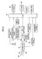
- This biosensor measurement machine 20includes a power source 21, which is connected to a controller 24, a measurement instrument 23 and a voltage regulator 22 for supplying power.
- the voltage regulator 22can apply a voltage to the biosensor chip 1, and through the application of a voltage to the electrodes 3 and 4 (see Fig. 1 ), can obtain information produced by a biochemical reaction in a sample stored in the biosensor chip 1.
- the biosensor chip 1is connected to the measurement instrument 23, and can obtain from the measurement instrument 23 a numerical value, or a signal, carrying information relative to a biochemical reaction in a sample.
- the measurement instrument 23is connected to the controller 24 that provides a variety of control functions, and data or information measured by the measurement instrument 23 is transmitted to the controller, which then performs a computation process.
- the controller 24includes a control circuit for determining whether a data value measured by the measurement instrument 23 is greater or smaller than a predesignated value (a threshold value, a reference value, etc.), and can employ the control circuit to determine whether a measurement should be performed. Furthermore, a plurality of different reference values that are employed for a determination made for the continuation/termination of a measurement are also stored, and the continuation/termination of a measurement can be designated in accordance with the value levels. Further, a standard curve table is stored in the controller 24, and in accordance with the continuation/termination of a measurement, a desired standard curve can be selected and the measurement results produced by a biosensor chip can be computed/calculated to obtain accurate measurement results. In addition, the controller 24 is connected to a display device 25, so that the measurement results can be displayed on the display device 25, or can be stored in a storage device incorporated in the display device 25, and can, for example, be compared with measurement results obtained in the past.
- a predesignated valuea threshold value, a reference value,
- a biosensor measurement systemcan also be arranged by employing the described biosensor measurement machine and the biosensor chip shown in Fig. 1 .
- a connectoris provided for the biosensor measurement machine, and the distal end of the biosensor chip is inserted in the connector to render the two electrodes conductive, so that a sample present within the biosensor chip can be measured.
- the biosensor chip shown in Fig. 1can be used only once, for a single measurement (is a so-called disposable), and a person performing a self-measurement can easily conduct the measurement at home, etc.
- the sampleis introduced in the reaction space of the biosensor chip, and a measurement using the measurement machine is performed by connecting the biosensor chip to the measurement machine.
- the measurement resultscan be obtained.
- a person performing a self-measurementcan easily prepare for and conduct a measurement, and can immediately obtain measurement results.
- Fig. 3is a flowchart for explaining the process for a blood sugar level measurement method.
- the electrode portions at the distal ends of a biosensor chipare connected to the connector of the measurement machine.
- step 2 (S2)a sample is introduced in the reaction space of the biosensor chip. It is preferable that the biosensor chip shown in Fig. 1 be employed, and that the volume of the reaction space (cavity) be equal to or smaller than 300 nl (nanoliters) .
- glucose oxidaseGDO
- glucose oxidaseSince glucose oxidase has a satisfactory sensitivity characteristic and has a quick response time, an accurate measurement is enabled within a short period of time.
- step S2When a sample is introduced in the reaction space of the biosensor chip in a state wherein a voltage is applied, electric conducting of the electrodes is started, so that the introduction of the sample can be detected.
- step S2After step S2 has ended, a settling period of about several seconds to several tens of seconds may be designated, so that the blood sample and the enzyme contained in the drug satisfactorily react with each other in the reaction space of the biosensor chip.
- program controlis shifted to step 3 (S3), and a voltage is applied to the biosensor chip by the voltage regulator.
- the controllerbegins counting time, and the measurement instrument begins measurement of a current value. Examples of the thus obtained time-transient protocols for a current and a voltage are shown in Fig. 4 .
- step 4the current value of the biosensor chip upon the elapse of five seconds is measured.
- the control circuit of the controlleris started and performs a comparison to determine whether the current value is smaller or greater than a predesignated value (a reference value) that is set for the control circuit.
- the predesignated setup current valuereference value
- step 5a comparison between the measured value and the reference value is performed.
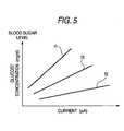
- Computation of the blood sugar levelcan be performed by employing a standard curve table stored in the controller, and an example of this standard curve table is shown in Fig. 5 .
- a standard curve table shown in Fig. 5a plurality of different standard curves are provided for a relationship between a glucose concentration and a current, and in accordance with a measurement condition, a standard curve to be used for computation of a blood sugar level is determined.
- a standard curve f1is employed for blood sugar level computation at step 7 (S7).
- the glucose concentrationis obtained based on a relationship between the measured current value and the standard curve f1, and finally, a blood sugar level is obtained.
- step 5When, at step 5 (S5), the measured current value for the biosensor chip is smaller than 2 ⁇ A, program control advances to step 8 (S8), and measurement of the current value is continued.
- step 9a current value upon the elapse of ten seconds is measured
- step 10program control advances to step 10 (S10), and computation of a blood sugar level is performed.
- the glucose concentration upon an elapse of ten secondsis obtained by employing a standard curve f2 in the standard curve table in Fig. 5 , and a blood sugar level is obtained.
- step 4S4
- step 10S10
- the vertical axis in this drawingrepresents a current value measured by the measurement instrument
- the horizontal axisrepresents the elapsed time from the start of a measurement.
- a biosensor chip processed through step 5, step 6 and step 7is a first biosensor chip
- a biosensor chip processed from step 5 to step 8 through step 10is a second biosensor chip.
- ⁇indicates a current curve obtained through measurement of a sample A stored in the first biosensor chip
- ⁇indicates a current curve obtained through the measurement of a sample B stored in the second biosensor chip.
- the inclination of the current curve ⁇ of the sample Abecomes quite small, and the current curve starts substantially constantly in the vicinity of about 2.8 ⁇ A.
- the current valueexceeds the reference value of 2 ⁇ A, the measurement of the current value for the sample A is terminated, and the blood sugar level is computed using the standard curve f1 (see Fig. 5 ) that is consonant with the condition at the end of five seconds.
- an impurity in the bloodaffects the measured value.
- a current value fluctuationthat is derived from a phenomenon such that, during the introduction of a sample, air remains as bubbles on the surfaces of the electrodes, instead of being immediately removed, and the bubbles gradually escape from the surfaces of the electrodes.
- a drugsuch as an enzyme
- a process for dissolving the enzyme, etc.in the sample is required.
- the measured current valueis about 0.8 ⁇ A, which is lower than the reference current value of 2 ⁇ A, and the measurement of the current value is continued for another five seconds.
- the measured current valueis almost constant, i.e., 0.7 ⁇ A. The measurement is terminated at this point, and the blood sugar level for the sample B is computed using the standard curve f2 that is consonant with the condition at the end of ten seconds.
- the case for the sample Ais that a sample is indicated that has a high glucose concentration, i.e., has a high blood sugar level, and the sample B indicates a sample having a low glucose concentration and a low blood sugar level.
- a sample having a high blood sugar levelprovides a high reaction level between glucose and an enzyme, a large amount of a current flows through the sample. As a result, comparatively, the sample is less affected by the reaction produced, for example, by an impurity, so that a stable measured value can be obtained even when the measurement is ended comparatively shortly after a voltage is applied.
- the absolute value of a current generated by this reactionis also small.
- a threshold current valueis predesignated, and a measurement is immediately terminated for a biosensor for a sample that exceeds the threshold value. In this manner, an accurate blood sugar value can be obtained within a short period of time.
- a sample having a high blood sugar levelhere indicates a sample that falls within the range of a concentration equal to or higher than 30 to 50 mg/dL, in a case for a glucose sensor having a cavity volume of 1 to 5 ⁇ L. At this time, depending on the enzyme to be used and the electrode type, generally about 2 to 10 seconds is required as a period for removing the effect, for example, of an impurity.
- a sample having a low blood sugar levelindicates a glucose concentration of equal to or lower than 30 to 50 mg/dL. At this time, a period of about 5 to 30 seconds is required to remove the effect, for example, of an impurity.
- the glucose concentration within this rangefalls outside the normal concentration range (50 to 150 mg/dL) for a human being, a frequency for measuring this concentration is low.
- this glucose concentrationis within a concentration range that is used as a determination reference to determine whether insulin should be provided for a type I diabetes mellitus patient, whether accurate measurement is available within this concentration range is important in order to extend the application range of the measurement machine.
- inexpensive carbon electrodesare employed as those for a sensor, the convergence of a current value is delayed because the resistance is great, and the measurement condition is adjusted to that for a low concentration area, so that a very long measurement period must be designated.
- the present inventionin a case for a low blood sugar level, the measurement results can also be quickly displayed following a short measurement period of time within the normal concentration range, while the accuracy of the measured value is maintained.
- the cavity volume of the normal glucose sensoris about 1 to 5 ⁇ L, and when the volume is smaller than 300 nL, the absolute amount of glucose is reduced. Therefore, there is a case wherein performing a measurement in a short period of time is difficult, even within a concentration range equal to or greater than 30 to 50 mg/dL, which is included in the normal blood sugar level range for a human being. Even in this case, when the method of this invention is employed, a measurement for only the minimum required concentration range can be limited as a measurement taken during a long period of time.
- the method of this inventionis especially useful when a sensor having a small cavity volume is to be manufactured using inexpensive carbon electrodes, without drastically increasing the cost.
- a blood sugar levelis obtained based on a current value measured by the biosensor chip.
- the measurement of a chargemay be performed to obtain an accurate blood sugar level within a short period of time.
- a charge valuecan be measured as an integral value for a current in accordance with the elapsed time indicated in the current curves ⁇ and ⁇ shown in Fig. 5 .
- a predesignated charge valuea reference charge value
- a current curve ⁇of a sample A for a first biosensor chip
- a current curve ⁇of a sample B for a second biosensor chip
- a current curve ⁇of a sample C for a third biosensor chip
- the current curve ⁇ and the current curve ⁇are the same as the current curves ⁇ and ⁇ shown in Fig. 6 .
- a first reference value Iis set to 2.2 ⁇ A
- a second reference value IIis set to 1.2 ⁇ A.
- the current values of the individual samples A, B and Care measured. Since, after an elapse of five seconds, the current curve ⁇ exceeds the first reference value I of 2.2 ⁇ A, the measurement of the sample A is terminated, and the standard curve f1 in Fig. 5 is employed to compute the blood sugar level of the sample A. Since the current curves for the samples B and C are below the first reference value I, the measurement of the current is continued, and upon an elapse of 7.5 seconds, whether the second reference value II of 1.2 ⁇ A is exceeded is determined.
- the standard curve Cis selected in accordance with the determination based on the second reference value, i.e., the standard curve f3 shown in Fig. 5 is employed to compute the blood sugar level of the sample C. Since the second threshold value is not exceeded for the sample B, upon the elapse of ten seconds from the start of the measurement, the measurement is terminated, and the blood sugar level of the sample B can be computed based on the standard curve f2.
- the standard curves f1, f2 and f3are two-dimensional linear lines having inherent, individual inclinations.
- a standard curve table for curvesa standard curve table including both linear lines and curves, or a standard curve table of a polyline type, may be employed.
- the type, for example, of the enzyme of a drug to be stored in the reaction space of a biosensor chipis varied, or when the size of a reaction space, a temperature, etc., differs, a difference occurs in data obtained through measurement (a current value, a charge value, etc.).
- a standard curve table stored in the controllerneed be changed, for an accurate blood sugar level to be quickly measured.
- calibration informationmay be stored in the controller, and in accordance with the condition of a biosensor chip or the characteristic of a measurement machine, a calibration factor may be employed when a blood sugar level is computed based on a standard curve. In this manner, a blood sugar level can more accurately be obtained.
Landscapes
- Health & Medical Sciences (AREA)
- Chemical & Material Sciences (AREA)
- Life Sciences & Earth Sciences (AREA)
- Analytical Chemistry (AREA)
- General Health & Medical Sciences (AREA)
- Chemical Kinetics & Catalysis (AREA)
- Electrochemistry (AREA)
- Physics & Mathematics (AREA)
- Pathology (AREA)
- Biochemistry (AREA)
- Immunology (AREA)
- General Physics & Mathematics (AREA)
- Molecular Biology (AREA)
- Hematology (AREA)
- Investigating Or Analysing Biological Materials (AREA)
- Measurement Of The Respiration, Hearing Ability, Form, And Blood Characteristics Of Living Organisms (AREA)
- Apparatus Associated With Microorganisms And Enzymes (AREA)
- Investigating Or Analyzing Materials By The Use Of Electric Means (AREA)
Description
- The present invention relates to a biosensor measurement machine that employs a biosensor chip to measure chemical substances, and a biosensor measurement system and a biosensor measurement method.
- To perform a measurement by employing a biosensor chip, a sample to be measured is introduced in the reaction portion of a biosensor, a biochemical reaction, such as an enzymatic reaction or an antigen-antibody reaction, is generated in the reaction portion, and information obtained through this biochemical reaction is output, by the biosensor chip, to a measurement apparatus that analyzes the sample. A measurement method employing a biosensor chip is performed by employing a superior molecular recognition function possessed by an organism, and has drawn attention as a method for enabling the performance of a quick and simple measurement of a chemical substance by employing only a tiny amount of a sample. As an example, the measurement method using a biosensor chip can be employed to measure the glucose content of blood (blood sugar level) or a urine sugar level, and can be used, for example, for a home health examination (self-care) for the self-control and management of diabetes.
- A measurement method using a biosensor chip described in
patent document 1 is known. According to this biosensor measurement method, as shown inFig. 8 , abiosensor 100 includes twoleads leads terminals connector 103. When thebiosensor 100 is connected to theconnector 103, a voltage is applied using abattery 106, the resistances of electrodes are changed by a sample present in thebiosensor 100, and the system function is initiated. Then, amicrocomputer 107 detects, through an A/D converter 109, a change in a voltage output by a current/voltage converter 108, and starts a measurement timer. At the same time, aswitch 110 is closed, and the two electrodes of thebiosensor 100 are short-circuited, so that the two electrodes can be set to equal potential states, i.e., to states near a potential difference of 0 V. As a result, a potential difference that occurred between the two electrodes can be easily removed. - As another example, a measurement method employing a biosensor chip described in
patent document 2 is known. According to this measurement method for employing a biosensor, as shown inFig. 9 , abiosensor 200 and aconnector 201 are connected byresistors connector 201. And a GDO enzyme, a potassium ferricyanide electron acceptor, a phosphate buffer solution and a glucose substrate are introduced in the electrode system and a current flowing through the electrode system is measured. The current is detected by adetection circuit 204, and is converted into a voltage signal by a current/voltage converter 205. The thus obtained voltage signal is converted into a digital signal by an A/D converter 206, the digital signal is processed by aCPU 207 and a resultant signal is output to anLCD display device 208 and can also be recorded in amemory 209. - Patent Document 1: Japanese Patent Application Laid-Open:
JP-A-8-15220 - Patent Document 2: Japanese Patent Application Laid-Open:
JP-A-9-274010 - In a conventional case of the use of a biosensor chip for measuring a sample, almost the same period of time is required for any measurement, regardless of whether the concentration of a measurement sample is high or low. Further, a long measurement period, e.g., several tens of seconds, is required in order to obtain precise measurement results. However, depending on the concentration of a measurement sample, precise results can be obtained within a short measurement period, and a reduction in the length of the measurement period has been requested. Furthermore, demands for measurements performed using biosensor chips have increased, and in accordance with the increase in the measurements demands, multiple measurement samples must be handled within a short period of time. One objective of the present invention is to provide a biosensor measurement machine, and a measurement method therefor, whereby a measurement can be ended within a short period of time and accurate measurement results can be obtained.
- According to the present invention, there is provided a biosensor measurement machine as set out in
claim 1. - Preferably, a plurality of different values are provided for use as predesigned reference values.
- The comparison of the current value or the charge value with a reference value includes a case wherein a calculation process is performed for a current value or a charge value, and the obtained value is employed for a comparison.
- In addition, a plurality of different standard curve tables may be stored in said control unit.
- There may also be provided a biosensor measurement system including:
- a biosensor measurement machine as described above, and
- a biosensor chip.
- The biosensor chip may include glucose oxidase as an enzyme, and has a cavity volume equal to or smaller than 300 nl (nanoliters).
- According to the present invention, there is also provided a biosensor measurement method as set out in
claim 6. - According to the biosensor measurement machine and the measurement method of the present invention, since whether a measurement is to be continued is determined based on a current value or a charge value that has been measured, the measurement can be terminated within a short period of time and accurate measurement results can be obtained.
- [
Fig. 1 ]Fig. 1 shows an overview of a biosensor chip, withFig. 1(a) being an explanatory view, taken from a side face, andFig. 1(b) being an explanatory view, taken from a top face. - [
Fig. 2 ]Fig. 2 is a schematic diagram for explaining a biosensor measurement machine embodying the present invention. - [
Fig. 3 ]Fig. 3 is a flowchart showing an example biosensor measurement method embodying the present invention. - [
Fig. 4 ]Fig. 4 is a diagram showing an example time-transient protocol for a voltage and a current that are measured. - [
Fig. 5 ]Fig. 5 is a diagram showing an example standard curve table. - [
Fig. 6 ]Fig. 6 is a diagram showing the elapsed time for currents measured by two biosensor chips. - [
Fig. 7 ]Fig. 7 is a diagram showing the elapsed time for currents measured by three biosensor chips. - [
Fig. 8 ]Fig. 8 is an explanatory diagram for explaining a conventional biosensor measurement method. - [
Fig. 9 ]Fig. 9 is an explanatory diagram for explaining another example conventional biosensor measurement method. - 1: biosensor chip
- 2: substrate
- 3, 4: electrode
- 6: reaction space
- 10: drug
- 11A, 11B: sheet member
- 20: biosensor measurement machine
- 21: power source
- 22: voltage regulator
- 23: measurement instrument
- 24: controller
- 25: display device
- A biosensor measurement machine, a biosensor measurement system and a biosensor measurement method exemplifying the present invention will be described in detail below, while referring to drawings.
- First, the overview of a biosensor will be described. An example in
Fig. 1 shows the main arrangement of a biosensor chip:Fig. 1(a) is an explanatory view, taken from the side face, andFig. 1 (b) is an explanatory view, taken from the top face. Abiosensor chip 1 includes asubstrate 2 that is folded into almost a U shape in cross section, and on one of the surfaces of thesubstrate 2, twoelectrodes electrodes substrate 2 on which theelectrodes adhesive layers hollow reaction space 6.First spacer members adhesive layers second spacers adhesive layers second spacers substrate 2 are bonded usingadhesives reaction space 6 is defined by thesubstrate 2 that is folded into a U shape, and afront sheet member 11A and arear sheet member 11B, which are formed by laminating the adhesive layers and the spacer members. The twoelectrodes reaction space 6. In addition, adrug 10 such as a catalyst or an enzyme is applied on theelectrodes - A biosensor measurement machine embodying the present invention will now be described. An overview of the biosensor measurement machine is shown in
Fig. 2 . Thisbiosensor measurement machine 20 includes apower source 21, which is connected to acontroller 24, ameasurement instrument 23 and avoltage regulator 22 for supplying power. Thevoltage regulator 22 can apply a voltage to thebiosensor chip 1, and through the application of a voltage to theelectrodes 3 and 4 (seeFig. 1 ), can obtain information produced by a biochemical reaction in a sample stored in thebiosensor chip 1. Further, thebiosensor chip 1 is connected to themeasurement instrument 23, and can obtain from the measurement instrument 23 a numerical value, or a signal, carrying information relative to a biochemical reaction in a sample. Themeasurement instrument 23 is connected to thecontroller 24 that provides a variety of control functions, and data or information measured by themeasurement instrument 23 is transmitted to the controller, which then performs a computation process. - The
controller 24 includes a control circuit for determining whether a data value measured by themeasurement instrument 23 is greater or smaller than a predesignated value (a threshold value, a reference value, etc.), and can employ the control circuit to determine whether a measurement should be performed. Furthermore, a plurality of different reference values that are employed for a determination made for the continuation/termination of a measurement are also stored, and the continuation/termination of a measurement can be designated in accordance with the value levels. Further, a standard curve table is stored in thecontroller 24, and in accordance with the continuation/termination of a measurement, a desired standard curve can be selected and the measurement results produced by a biosensor chip can be computed/calculated to obtain accurate measurement results. In addition, thecontroller 24 is connected to a display device 25, so that the measurement results can be displayed on the display device 25, or can be stored in a storage device incorporated in the display device 25, and can, for example, be compared with measurement results obtained in the past. - A biosensor measurement system can also be arranged by employing the described biosensor measurement machine and the biosensor chip shown in
Fig. 1 . In this case, a connector is provided for the biosensor measurement machine, and the distal end of the biosensor chip is inserted in the connector to render the two electrodes conductive, so that a sample present within the biosensor chip can be measured. The biosensor chip shown inFig. 1 can be used only once, for a single measurement (is a so-called disposable), and a person performing a self-measurement can easily conduct the measurement at home, etc. In this case, after an organic sample is taken by the person performing the self-measurement, the sample is introduced in the reaction space of the biosensor chip, and a measurement using the measurement machine is performed by connecting the biosensor chip to the measurement machine. In this manner, the measurement results can be obtained. As described above, using the described biosensor measurement system, without a special skill being required, a person performing a self-measurement can easily prepare for and conduct a measurement, and can immediately obtain measurement results. - Next, the biosensor measurement method exemplifying the present invention will be described, as applied, for example, to a method used to measure a blood sugar level.
Fig. 3 is a flowchart for explaining the process for a blood sugar level measurement method. At the first step 1 (S1), the electrode portions at the distal ends of a biosensor chip are connected to the connector of the measurement machine. When the connection to the biosensor chip is completed, at step 2 (S2), a sample is introduced in the reaction space of the biosensor chip. It is preferable that the biosensor chip shown inFig. 1 be employed, and that the volume of the reaction space (cavity) be equal to or smaller than 300 nl (nanoliters) . When the reaction space has a tiny volume equal to or smaller than 300 nl, a person performing a self-measurement need only take a little blood, and accordingly, only a short period is required to take the blood. Further, since a styptic procedure can be performed in only a short period of time, the blood taking burden for a person performing a self-measurement can be reduced. It is also preferable that glucose oxidase (GDO) be used as the enzyme that is the drug to be located in the reaction space. Since glucose oxidase has a satisfactory sensitivity characteristic and has a quick response time, an accurate measurement is enabled within a short period of time. - When a sample is introduced in the reaction space of the biosensor chip in a state wherein a voltage is applied, electric conducting of the electrodes is started, so that the introduction of the sample can be detected. After step S2 has ended, a settling period of about several seconds to several tens of seconds may be designated, so that the blood sample and the enzyme contained in the drug satisfactorily react with each other in the reaction space of the biosensor chip. Following this, program control is shifted to step 3 (S3), and a voltage is applied to the biosensor chip by the voltage regulator. When the voltage is applied to the biosensor chip, the controller begins counting time, and the measurement instrument begins measurement of a current value. Examples of the thus obtained time-transient protocols for a current and a voltage are shown in
Fig. 4 . - When five seconds have elapsed since the start of the measurement, at step 4 (S4), the current value of the biosensor chip upon the elapse of five seconds is measured. At this time, the control circuit of the controller is started and performs a comparison to determine whether the current value is smaller or greater than a predesignated value (a reference value) that is set for the control circuit. In this mode, the predesignated setup current value (reference value) is 2 µA, and at step 5 (S5), a comparison between the measured value and the reference value is performed. When the measured value is greater than 2 µA, program control advances to step 6 (S6) and terminates measurement of the current value. Then, program control advances to step 7 (S7), and a blood sugar level is computed. Computation of the blood sugar level can be performed by employing a standard curve table stored in the controller, and an example of this standard curve table is shown in
Fig. 5 . In the standard curve table shown inFig. 5 , a plurality of different standard curves are provided for a relationship between a glucose concentration and a current, and in accordance with a measurement condition, a standard curve to be used for computation of a blood sugar level is determined. After program control has advanced to step 6 (S6), a standard curve f1 is employed for blood sugar level computation at step 7 (S7).. The glucose concentration is obtained based on a relationship between the measured current value and the standard curve f1, and finally, a blood sugar level is obtained. - When, at step 5 (S5), the measured current value for the biosensor chip is smaller than 2 µA, program control advances to step 8 (S8), and measurement of the current value is continued. Sequentially, at step 9 (S9), a current value upon the elapse of ten seconds is measured, program control advances to step 10 (S10), and computation of a blood sugar level is performed. When the process has been shifted to step 8 (S8), the glucose concentration upon an elapse of ten seconds is obtained by employing a standard curve f2 in the standard curve table in
Fig. 5 , and a blood sugar level is obtained. - The process from step 4 (S4) to step 10 (S10) will be explained based on
Fig. 6 . The vertical axis in this drawing represents a current value measured by the measurement instrument, and the horizontal axis represents the elapsed time from the start of a measurement. In the flowchart inFig. 3 , a biosensor chip processed throughstep 5,step 6 andstep 7 is a first biosensor chip, and a biosensor chip processed fromstep 5 to step 8 throughstep 10 is a second biosensor chip. α indicates a current curve obtained through measurement of a sample A stored in the first biosensor chip, and β indicates a current curve obtained through the measurement of a sample B stored in the second biosensor chip. For both of the samples A and B, a trend is observed in that, immediately after the measurement is started, the current value is sharply raised to near 5 µA. The main factor for this trend is the reaction of glucose on the surfaces of the electrodes, and an impurity that is attached to the surfaces of the electrodes, and that is contained in blood, more or less affects the magnitude of the current value. After the current values of the samples A and B have been sharply raised, the reaction of glucose located separate from the electrodes is diffused and propagated to the electrodes, and accordingly, a current is supplied. However, the current value starts to be lowered in accordance with the diffusion velocity, and the inclinations of the two curves α and β begin to converge. When five seconds have elapsed, the inclination of the current curve α of the sample A becomes quite small, and the current curve starts substantially constantly in the vicinity of about 2.8 µA. Here, the current value exceeds the reference value of 2 µA, the measurement of the current value for the sample A is terminated, and the blood sugar level is computed using the standard curve f1 (seeFig. 5 ) that is consonant with the condition at the end of five seconds. - As described above, an impurity in the blood affects the measured value. As a factor, other than an impurity, of the time-transient fluctuation of a current value, there is a current value fluctuation that is derived from a phenomenon such that, during the introduction of a sample, air remains as bubbles on the surfaces of the electrodes, instead of being immediately removed, and the bubbles gradually escape from the surfaces of the electrodes. Further, in order to permit a drug, such as an enzyme, to react with glucose in a sample, a process for dissolving the enzyme, etc., in the sample is required. There is also a current value fluctuation that is due to the fact that much time is required for this dissolution. Either way, since these fluctuations are near zero after a predetermined period has elapsed, in accordance with the elapse of time, the measured current value converges to a value based on a glucose reaction.
- As for the sample B, when five seconds have elapsed, the measured current value is about 0.8 µA, which is lower than the reference current value of 2 µA, and the measurement of the current value is continued for another five seconds. When ten seconds have elapsed from the start of the measurement, the measured current value is almost constant, i.e., 0.7 µA. The measurement is terminated at this point, and the blood sugar level for the sample B is computed using the standard curve f2 that is consonant with the condition at the end of ten seconds.
- The case for the sample A is that a sample is indicated that has a high glucose concentration, i.e., has a high blood sugar level, and the sample B indicates a sample having a low glucose concentration and a low blood sugar level. Generally, since a sample having a high blood sugar level provides a high reaction level between glucose and an enzyme, a large amount of a current flows through the sample. As a result, comparatively, the sample is less affected by the reaction produced, for example, by an impurity, so that a stable measured value can be obtained even when the measurement is ended comparatively shortly after a voltage is applied. On the other hand, since a sample having a low blood sugar level provides a low reaction level between glucose and an enzyme, the absolute value of a current generated by this reaction is also small. Thus, a little period of time is required before a stable current value is obtained. Therefore, a threshold current value is predesignated, and a measurement is immediately terminated for a biosensor for a sample that exceeds the threshold value. In this manner, an accurate blood sugar value can be obtained within a short period of time.
- A sample having a high blood sugar level here indicates a sample that falls within the range of a concentration equal to or higher than 30 to 50 mg/dL, in a case for a glucose sensor having a cavity volume of 1 to 5 µL. At this time, depending on the enzyme to be used and the electrode type, generally about 2 to 10 seconds is required as a period for removing the effect, for example, of an impurity. On the other hand, a sample having a low blood sugar level indicates a glucose concentration of equal to or lower than 30 to 50 mg/dL. At this time, a period of about 5 to 30 seconds is required to remove the effect, for example, of an impurity. Since the glucose concentration within this range falls outside the normal concentration range (50 to 150 mg/dL) for a human being, a frequency for measuring this concentration is low. However, since this glucose concentration is within a concentration range that is used as a determination reference to determine whether insulin should be provided for a type I diabetes mellitus patient, whether accurate measurement is available within this concentration range is important in order to extend the application range of the measurement machine. Especially in a case wherein inexpensive carbon electrodes are employed as those for a sensor, the convergence of a current value is delayed because the resistance is great, and the measurement condition is adjusted to that for a low concentration area, so that a very long measurement period must be designated. However, when the present invention is employed, in a case for a low blood sugar level, the measurement results can also be quickly displayed following a short measurement period of time within the normal concentration range, while the accuracy of the measured value is maintained.
- Furthermore, recently, a small cavity volume is requested to reduce the load when a person performing a self-measurement takes blood. The cavity volume of the normal glucose sensor is about 1 to 5 µL, and when the volume is smaller than 300 nL, the absolute amount of glucose is reduced. Therefore, there is a case wherein performing a measurement in a short period of time is difficult, even within a concentration range equal to or greater than 30 to 50 mg/dL, which is included in the normal blood sugar level range for a human being. Even in this case, when the method of this invention is employed, a measurement for only the minimum required concentration range can be limited as a measurement taken during a long period of time. Therefore, while the blood taking load for a person performing a self-measurement is reduced, the loss of the measurement period can be minimized. The method of this invention is especially useful when a sensor having a small cavity volume is to be manufactured using inexpensive carbon electrodes, without drastically increasing the cost.
- According to the above described mode, a blood sugar level is obtained based on a current value measured by the biosensor chip. However, instead of the measurement of a current value, the measurement of a charge may be performed to obtain an accurate blood sugar level within a short period of time. As an example, a charge value can be measured as an integral value for a current in accordance with the elapsed time indicated in the current curves α and β shown in
Fig. 5 . Thus, by setting a predesignated charge value (a reference charge value), whether the measurement of a sample should be ended or performed can be determined. - Furthermore, in the description of the above described mode, only one current value has been set as a reference. However, a plurality of predesignated setup, current values may be employed to compute a blood sugar level. A mode for measuring a blood sugar level using two predesignated setup values will be explained based on
Fig. 7 . InFig. 7 , a current curve α, of a sample A for a first biosensor chip, a current curve β, of a sample B for a second biosensor chip, and a current curve γ, of a sample C for a third biosensor chip, are shown. The current curve α and the current curve β are the same as the current curves α and β shown inFig. 6 . As two predesignated current reference values, a first reference value I is set to 2.2 µA, and a second reference value II is set to 1.2 µA. - The current values of the individual samples A, B and C are measured. Since, after an elapse of five seconds, the current curve α exceeds the first reference value I of 2.2 µA, the measurement of the sample A is terminated, and the standard curve f1 in
Fig. 5 is employed to compute the blood sugar level of the sample A. Since the current curves for the samples B and C are below the first reference value I, the measurement of the current is continued, and upon an elapse of 7.5 seconds, whether the second reference value II of 1.2 µA is exceeded is determined. As a result, it is determined that the current curve γ exceeds the second reference value and measurement of the sample C is terminated, and the standard curve C is selected in accordance with the determination based on the second reference value, i.e., the standard curve f3 shown inFig. 5 is employed to compute the blood sugar level of the sample C. Since the second threshold value is not exceeded for the sample B, upon the elapse of ten seconds from the start of the measurement, the measurement is terminated, and the blood sugar level of the sample B can be computed based on the standard curve f2. As described above, when a plurality of different reference values (predesignated values) are set, and a plurality of different measurement periods are set, an accurate measurement can be conducted in a short period of time, in accordance with the concentration of the sample stored in the biosensor chip. - In the standard curve table in
Fig. 5 , the standard curves f1, f2 and f3 are two-dimensional linear lines having inherent, individual inclinations. However, in accordance with the biosensor chip to be used and other conditions, a standard curve table for curves, a standard curve table including both linear lines and curves, or a standard curve table of a polyline type, may be employed. When the type, for example, of the enzyme of a drug to be stored in the reaction space of a biosensor chip is varied, or when the size of a reaction space, a temperature, etc., differs, a difference occurs in data obtained through measurement (a current value, a charge value, etc.). Therefore, in accordance with the condition of a biosensor chip to be measured, only a standard curve table stored in the controller need be changed, for an accurate blood sugar level to be quickly measured. Further, calibration information may be stored in the controller, and in accordance with the condition of a biosensor chip or the characteristic of a measurement machine, a calibration factor may be employed when a blood sugar level is computed based on a standard curve. In this manner, a blood sugar level can more accurately be obtained.
Claims (6)
- A biosensor measurement machine for performing a measurement employing a biosensor chip having a reaction portion in which a sample is introduced and a biochemical reaction is generated through which information obtained is output to the machine for determining an analyte concentration of the sample, said machine comprising:a voltage application unit (22) for applying a voltage to the biosensor chip (1); anda measurement unit arranged to measure current generated by the voltage application unit when applying said voltage to the biosensor chip, and to obtain a value for said current measured at the end of a predetermined initial measurement time period;characterised bya control unit (24), configured to determine whether measuring of said current should be continued for a further measurement time period if the obtained current value is smaller than a predesigned reference value, or the measuring terminated at the end of the initial measurement time period and said measured current value be used for determining an analyte concentration of the sample on the basis of the measured current value obtained at the end of the initial measurement time period if the obtained current value is greater than the predesigned reference value.
- The biosensor measurement machine according to claim 1, wherein a plurality of different values are provided for use as said predesigned reference value.
- The biosensor measurement machine according to claim 1 or 2, wherein
a plurality of different standard curve tables are stored in said control unit (24). - A biosensor measurement system comprising:a biosensor measurement machine according to any one of claims 1 to 3, anda biosensor chip (1).
- The biosensor measurement system according to claim 4, wherein
a biosensor chip (1) includes glucose oxidase as an enzyme, and has a cavity volume equal to or smaller than 300 nl (nanoliters). - A biosensor measurement method comprising the steps of:introducing a sample in the reaction portion of a biosensor chip;applying a voltage to the biosensor chip; andmeasuring current generated by application of the voltage and obtaining a value for said current measured at the end of a predetermined initial measurement time period;characterised bydetermining that measuring of said current should be continued for a further measurement time period if the obtained current value is smaller than a predesigned reference value, or that the measuring be terminated at the end of the initial measurement time period and said measured current value be used for determining an analyte concentration of the sample on the basis of the measured current value obtained at the end of the initial measurement time period if the obtained current value is greater than the predesigned reference value.
Applications Claiming Priority (2)
| Application Number | Priority Date | Filing Date | Title |
|---|---|---|---|
| JP2005267706 | 2005-09-14 | ||
| PCT/JP2006/317897WO2007032286A1 (en) | 2005-09-14 | 2006-09-08 | Bio-sensor measuring device, bio-sensor measuring system, and bio-sensor measuring method |
Publications (3)
| Publication Number | Publication Date |
|---|---|
| EP1927850A1 EP1927850A1 (en) | 2008-06-04 |
| EP1927850A4 EP1927850A4 (en) | 2011-09-14 |
| EP1927850B1true EP1927850B1 (en) | 2015-04-15 |
Family
ID=37864880
Family Applications (1)
| Application Number | Title | Priority Date | Filing Date |
|---|---|---|---|
| EP06797723.1AActiveEP1927850B1 (en) | 2005-09-14 | 2006-09-08 | Bio-sensor measuring device, bio-sensor measuring system, and bio-sensor measuring method |
Country Status (12)
| Country | Link |
|---|---|
| US (1) | US8282813B2 (en) |
| EP (1) | EP1927850B1 (en) |
| JP (1) | JP4862195B2 (en) |
| KR (1) | KR101299275B1 (en) |
| CN (1) | CN101263383B (en) |
| AU (1) | AU2006290025B2 (en) |
| CA (1) | CA2619703A1 (en) |
| ES (1) | ES2535657T3 (en) |
| NO (1) | NO20081343L (en) |
| RU (1) | RU2008114401A (en) |
| TW (1) | TWI396842B (en) |
| WO (1) | WO2007032286A1 (en) |
Families Citing this family (9)
| Publication number | Priority date | Publication date | Assignee | Title |
|---|---|---|---|---|
| AU2008279067A1 (en)* | 2007-07-26 | 2009-01-29 | Nipro Diagnostics, Inc. | System and methods for determination of analyte concentration using time resolved amperometry |
| US8101062B2 (en) | 2007-07-26 | 2012-01-24 | Nipro Diagnostics, Inc. | System and methods for determination of analyte concentration using time resolved amperometry |
| US8760178B2 (en) | 2009-09-30 | 2014-06-24 | Arkray, Inc. | Method for measuring target component in erythrocyte-containing specimen |
| JP5350960B2 (en)* | 2009-09-30 | 2013-11-27 | アークレイ株式会社 | Method for measuring target components in erythrocyte-containing samples |
| CN103930776B (en) | 2011-09-14 | 2017-05-24 | 明尼苏达大学董事会 | Field-free magnetic biosensor |
| CN103987654A (en)* | 2011-10-19 | 2014-08-13 | 明尼苏达大学董事会 | Magnetic biomedical sensors and sensing systems for high-throughput biomolecular testing |
| CN103364458A (en)* | 2012-04-01 | 2013-10-23 | 郡是株式会社 | Measurement and display device |
| US9629577B2 (en) | 2012-05-07 | 2017-04-25 | Panasonic Healthcare Holdings Co., Ltd. | Biological information measurement device and biological information measurement method using same |
| TWI565946B (en) | 2015-04-20 | 2017-01-11 | 國立清華大學 | A method for biological detection and a biosensor thereof |
Family Cites Families (11)
| Publication number | Priority date | Publication date | Assignee | Title |
|---|---|---|---|---|
| US5352351A (en)* | 1993-06-08 | 1994-10-04 | Boehringer Mannheim Corporation | Biosensing meter with fail/safe procedures to prevent erroneous indications |
| JP3061351B2 (en) | 1994-04-25 | 2000-07-10 | 松下電器産業株式会社 | Method and apparatus for quantifying specific compounds |
| JPH09274010A (en) | 1996-04-04 | 1997-10-21 | Matsushita Electric Ind Co Ltd | Substrate quantification method |
| WO2001071328A1 (en)* | 2000-03-22 | 2001-09-27 | All Medicus Co., Ltd. | Electrochemical biosensor test strip with recognition electrode and readout meter using this test strip |
| WO2001079529A1 (en)* | 2000-04-17 | 2001-10-25 | Purdue Research Foundation | Biosensor and related method |
| EP2388587B1 (en)* | 2000-11-30 | 2018-01-10 | Panasonic Healthcare Holdings Co., Ltd. | Method of quantifying substrate |
| CN102012389B (en) | 2001-01-17 | 2013-04-10 | 爱科来株式会社 | Quantitative analyzing method and quantitative analyzer using sensor |
| ATE543091T1 (en)* | 2001-08-01 | 2012-02-15 | Arkray Inc | ANALYZER, ANALYZER |
| US7491310B2 (en) | 2001-10-12 | 2009-02-17 | Arkray, Inc. | Concentration measuring method and concentration measuring apparatus |
| US6872299B2 (en)* | 2001-12-10 | 2005-03-29 | Lifescan, Inc. | Passive sample detection to initiate timing of an assay |
| CN100504371C (en)* | 2002-07-25 | 2009-06-24 | 爱科来株式会社 | Sample analyzing method and sample analyzer |
- 2006
- 2006-09-08EPEP06797723.1Apatent/EP1927850B1/enactiveActive
- 2006-09-08USUS11/992,102patent/US8282813B2/ennot_activeExpired - Fee Related
- 2006-09-08WOPCT/JP2006/317897patent/WO2007032286A1/enactiveApplication Filing
- 2006-09-08JPJP2007535452Apatent/JP4862195B2/ennot_activeExpired - Fee Related
- 2006-09-08AUAU2006290025Apatent/AU2006290025B2/ennot_activeCeased
- 2006-09-08RURU2008114401/28Apatent/RU2008114401A/enunknown
- 2006-09-08CACA002619703Apatent/CA2619703A1/ennot_activeAbandoned
- 2006-09-08ESES06797723.1Tpatent/ES2535657T3/enactiveActive
- 2006-09-08KRKR1020087006050Apatent/KR101299275B1/ennot_activeExpired - Fee Related
- 2006-09-08CNCN2006800338755Apatent/CN101263383B/ennot_activeExpired - Fee Related
- 2006-09-12TWTW095133618Apatent/TWI396842B/ennot_activeIP Right Cessation
- 2008
- 2008-03-13NONO20081343Apatent/NO20081343L/ennot_activeApplication Discontinuation
Also Published As
| Publication number | Publication date |
|---|---|
| NO20081343L (en) | 2008-06-12 |
| CN101263383B (en) | 2012-03-07 |
| AU2006290025B2 (en) | 2011-10-20 |
| CN101263383A (en) | 2008-09-10 |
| US20090152127A1 (en) | 2009-06-18 |
| WO2007032286A1 (en) | 2007-03-22 |
| ES2535657T3 (en) | 2015-05-13 |
| EP1927850A1 (en) | 2008-06-04 |
| JPWO2007032286A1 (en) | 2009-03-19 |
| EP1927850A4 (en) | 2011-09-14 |
| TW200722747A (en) | 2007-06-16 |
| US8282813B2 (en) | 2012-10-09 |
| CA2619703A1 (en) | 2007-03-22 |
| KR20080069572A (en) | 2008-07-28 |
| KR101299275B1 (en) | 2013-08-23 |
| RU2008114401A (en) | 2009-10-20 |
| JP4862195B2 (en) | 2012-01-25 |
| TWI396842B (en) | 2013-05-21 |
| AU2006290025A1 (en) | 2007-03-22 |
Similar Documents
| Publication | Publication Date | Title |
|---|---|---|
| EP1927850B1 (en) | Bio-sensor measuring device, bio-sensor measuring system, and bio-sensor measuring method | |
| RU2606769C2 (en) | Glucose measurement method and system | |
| US7347925B2 (en) | Biosensor for monitoring an analyte content with a partial voltage generated therefrom | |
| RU2573612C2 (en) | System and method to detect electrochemical analyte | |
| CA2724911C (en) | Fill sufficiency method and system | |
| EP2678670B1 (en) | Capacitance detection in electrochemical assay with improved sampling time offset | |
| EP2539711B1 (en) | Capacitance detection in electrochemical assay | |
| US8773106B2 (en) | Capacitance detection in electrochemical assay with improved sampling time offset | |
| EP2956765B9 (en) | System and method for measuring an analyte in a sample and calculating hematocrit-insensitive glucose concentrations | |
| US7510642B2 (en) | Biosensor with improved reading resolution | |
| AU2015221473A1 (en) | Capacitance detection in electrochemical assay | |
| HK1217537B (en) | System and method for measuring an analyte in a sample and calculating hematocrit-insensitive glucose concentrations | |
| HK1179341B (en) | Capacitance detection in electrochemical assay | |
| HK1192945B (en) | Capacitance detection in electrochemical assay with improved sampling time offset |
Legal Events
| Date | Code | Title | Description |
|---|---|---|---|
| PUAI | Public reference made under article 153(3) epc to a published international application that has entered the european phase | Free format text:ORIGINAL CODE: 0009012 | |
| 17P | Request for examination filed | Effective date:20080226 | |
| AK | Designated contracting states | Kind code of ref document:A1 Designated state(s):AT BE BG CH CY CZ DE DK EE ES FI FR GB GR HU IE IS IT LI LT LU LV MC NL PL PT RO SE SI SK TR | |
| AX | Request for extension of the european patent | Extension state:HR | |
| A4 | Supplementary search report drawn up and despatched | Effective date:20110818 | |
| RIC1 | Information provided on ipc code assigned before grant | Ipc:G01N 27/416 20060101ALI20110811BHEP Ipc:G01N 27/327 20060101AFI20110811BHEP Ipc:G01N 33/487 20060101ALN20110811BHEP Ipc:G01N 27/04 20060101ALI20110811BHEP Ipc:G01N 27/26 20060101ALI20110811BHEP | |
| 17Q | First examination report despatched | Effective date:20120516 | |
| RAX | Requested extension states of the european patent have changed | Extension state:HR Payment date:20080226 | |
| GRAP | Despatch of communication of intention to grant a patent | Free format text:ORIGINAL CODE: EPIDOSNIGR1 | |
| RIC1 | Information provided on ipc code assigned before grant | Ipc:G01N 33/487 20060101ALN20141009BHEP Ipc:G01N 27/327 20060101AFI20141009BHEP Ipc:G01N 27/26 20060101ALI20141009BHEP Ipc:G01N 27/416 20060101ALI20141009BHEP Ipc:G01N 27/04 20060101ALI20141009BHEP | |
| RIC1 | Information provided on ipc code assigned before grant | Ipc:G01N 27/04 20060101ALI20141013BHEP Ipc:G01N 27/416 20060101ALI20141013BHEP Ipc:G01N 27/327 20060101AFI20141013BHEP Ipc:G01N 27/26 20060101ALI20141013BHEP Ipc:G01N 33/487 20060101ALN20141013BHEP | |
| INTG | Intention to grant announced | Effective date:20141027 | |
| GRAS | Grant fee paid | Free format text:ORIGINAL CODE: EPIDOSNIGR3 | |
| GRAA | (expected) grant | Free format text:ORIGINAL CODE: 0009210 | |
| AK | Designated contracting states | Kind code of ref document:B1 Designated state(s):AT BE BG CH CY CZ DE DK EE ES FI FR GB GR HU IE IS IT LI LT LU LV MC NL PL PT RO SE SI SK TR | |
| AX | Request for extension of the european patent | Extension state:HR | |
| REG | Reference to a national code | Ref country code:GB Ref legal event code:FG4D Ref country code:CH Ref legal event code:EP | |
| REG | Reference to a national code | Ref country code:IE Ref legal event code:FG4D | |
| REG | Reference to a national code | Ref country code:ES Ref legal event code:FG2A Ref document number:2535657 Country of ref document:ES Kind code of ref document:T3 Effective date:20150513 | |
| REG | Reference to a national code | Ref country code:AT Ref legal event code:REF Ref document number:722265 Country of ref document:AT Kind code of ref document:T Effective date:20150515 | |
| REG | Reference to a national code | Ref country code:DE Ref legal event code:R096 Ref document number:602006045138 Country of ref document:DE Effective date:20150528 | |
| REG | Reference to a national code | Ref country code:NL Ref legal event code:VDEP Effective date:20150415 | |
| REG | Reference to a national code | Ref country code:AT Ref legal event code:MK05 Ref document number:722265 Country of ref document:AT Kind code of ref document:T Effective date:20150415 | |
| REG | Reference to a national code | Ref country code:LT Ref legal event code:MG4D | |
| PG25 | Lapsed in a contracting state [announced via postgrant information from national office to epo] | Ref country code:NL Free format text:LAPSE BECAUSE OF FAILURE TO SUBMIT A TRANSLATION OF THE DESCRIPTION OR TO PAY THE FEE WITHIN THE PRESCRIBED TIME-LIMIT Effective date:20150415 | |
| PG25 | Lapsed in a contracting state [announced via postgrant information from national office to epo] | Ref country code:PT Free format text:LAPSE BECAUSE OF FAILURE TO SUBMIT A TRANSLATION OF THE DESCRIPTION OR TO PAY THE FEE WITHIN THE PRESCRIBED TIME-LIMIT Effective date:20150817 Ref country code:FI Free format text:LAPSE BECAUSE OF FAILURE TO SUBMIT A TRANSLATION OF THE DESCRIPTION OR TO PAY THE FEE WITHIN THE PRESCRIBED TIME-LIMIT Effective date:20150415 Ref country code:LT Free format text:LAPSE BECAUSE OF FAILURE TO SUBMIT A TRANSLATION OF THE DESCRIPTION OR TO PAY THE FEE WITHIN THE PRESCRIBED TIME-LIMIT Effective date:20150415 | |
| PG25 | Lapsed in a contracting state [announced via postgrant information from national office to epo] | Ref country code:AT Free format text:LAPSE BECAUSE OF FAILURE TO SUBMIT A TRANSLATION OF THE DESCRIPTION OR TO PAY THE FEE WITHIN THE PRESCRIBED TIME-LIMIT Effective date:20150415 Ref country code:GR Free format text:LAPSE BECAUSE OF FAILURE TO SUBMIT A TRANSLATION OF THE DESCRIPTION OR TO PAY THE FEE WITHIN THE PRESCRIBED TIME-LIMIT Effective date:20150716 Ref country code:LV Free format text:LAPSE BECAUSE OF FAILURE TO SUBMIT A TRANSLATION OF THE DESCRIPTION OR TO PAY THE FEE WITHIN THE PRESCRIBED TIME-LIMIT Effective date:20150415 Ref country code:IS Free format text:LAPSE BECAUSE OF FAILURE TO SUBMIT A TRANSLATION OF THE DESCRIPTION OR TO PAY THE FEE WITHIN THE PRESCRIBED TIME-LIMIT Effective date:20150815 | |
| REG | Reference to a national code | Ref country code:DE Ref legal event code:R097 Ref document number:602006045138 Country of ref document:DE | |
| PG25 | Lapsed in a contracting state [announced via postgrant information from national office to epo] | Ref country code:DK Free format text:LAPSE BECAUSE OF FAILURE TO SUBMIT A TRANSLATION OF THE DESCRIPTION OR TO PAY THE FEE WITHIN THE PRESCRIBED TIME-LIMIT Effective date:20150415 Ref country code:EE Free format text:LAPSE BECAUSE OF FAILURE TO SUBMIT A TRANSLATION OF THE DESCRIPTION OR TO PAY THE FEE WITHIN THE PRESCRIBED TIME-LIMIT Effective date:20150415 | |
| PLBE | No opposition filed within time limit | Free format text:ORIGINAL CODE: 0009261 | |
| STAA | Information on the status of an ep patent application or granted ep patent | Free format text:STATUS: NO OPPOSITION FILED WITHIN TIME LIMIT | |
| PG25 | Lapsed in a contracting state [announced via postgrant information from national office to epo] | Ref country code:RO Free format text:LAPSE BECAUSE OF NON-PAYMENT OF DUE FEES Effective date:20150415 Ref country code:CZ Free format text:LAPSE BECAUSE OF FAILURE TO SUBMIT A TRANSLATION OF THE DESCRIPTION OR TO PAY THE FEE WITHIN THE PRESCRIBED TIME-LIMIT Effective date:20150415 Ref country code:SK Free format text:LAPSE BECAUSE OF FAILURE TO SUBMIT A TRANSLATION OF THE DESCRIPTION OR TO PAY THE FEE WITHIN THE PRESCRIBED TIME-LIMIT Effective date:20150415 Ref country code:PL Free format text:LAPSE BECAUSE OF FAILURE TO SUBMIT A TRANSLATION OF THE DESCRIPTION OR TO PAY THE FEE WITHIN THE PRESCRIBED TIME-LIMIT Effective date:20150415 | |
| 26N | No opposition filed | Effective date:20160118 | |
| PG25 | Lapsed in a contracting state [announced via postgrant information from national office to epo] | Ref country code:MC Free format text:LAPSE BECAUSE OF FAILURE TO SUBMIT A TRANSLATION OF THE DESCRIPTION OR TO PAY THE FEE WITHIN THE PRESCRIBED TIME-LIMIT Effective date:20150415 Ref country code:LU Free format text:LAPSE BECAUSE OF FAILURE TO SUBMIT A TRANSLATION OF THE DESCRIPTION OR TO PAY THE FEE WITHIN THE PRESCRIBED TIME-LIMIT Effective date:20150908 | |
| REG | Reference to a national code | Ref country code:CH Ref legal event code:PL | |
| PG25 | Lapsed in a contracting state [announced via postgrant information from national office to epo] | Ref country code:SI Free format text:LAPSE BECAUSE OF FAILURE TO SUBMIT A TRANSLATION OF THE DESCRIPTION OR TO PAY THE FEE WITHIN THE PRESCRIBED TIME-LIMIT Effective date:20150415 | |
| REG | Reference to a national code | Ref country code:IE Ref legal event code:MM4A | |
| PG25 | Lapsed in a contracting state [announced via postgrant information from national office to epo] | Ref country code:IE Free format text:LAPSE BECAUSE OF NON-PAYMENT OF DUE FEES Effective date:20150908 Ref country code:CH Free format text:LAPSE BECAUSE OF NON-PAYMENT OF DUE FEES Effective date:20150930 Ref country code:LI Free format text:LAPSE BECAUSE OF NON-PAYMENT OF DUE FEES Effective date:20150930 | |
| REG | Reference to a national code | Ref country code:FR Ref legal event code:PLFP Year of fee payment:11 | |
| PG25 | Lapsed in a contracting state [announced via postgrant information from national office to epo] | Ref country code:BE Free format text:LAPSE BECAUSE OF FAILURE TO SUBMIT A TRANSLATION OF THE DESCRIPTION OR TO PAY THE FEE WITHIN THE PRESCRIBED TIME-LIMIT Effective date:20150415 | |
| PG25 | Lapsed in a contracting state [announced via postgrant information from national office to epo] | Ref country code:BG Free format text:LAPSE BECAUSE OF FAILURE TO SUBMIT A TRANSLATION OF THE DESCRIPTION OR TO PAY THE FEE WITHIN THE PRESCRIBED TIME-LIMIT Effective date:20150415 Ref country code:HU Free format text:LAPSE BECAUSE OF FAILURE TO SUBMIT A TRANSLATION OF THE DESCRIPTION OR TO PAY THE FEE WITHIN THE PRESCRIBED TIME-LIMIT; INVALID AB INITIO Effective date:20060908 | |
| PG25 | Lapsed in a contracting state [announced via postgrant information from national office to epo] | Ref country code:CY Free format text:LAPSE BECAUSE OF FAILURE TO SUBMIT A TRANSLATION OF THE DESCRIPTION OR TO PAY THE FEE WITHIN THE PRESCRIBED TIME-LIMIT Effective date:20150415 Ref country code:SE Free format text:LAPSE BECAUSE OF FAILURE TO SUBMIT A TRANSLATION OF THE DESCRIPTION OR TO PAY THE FEE WITHIN THE PRESCRIBED TIME-LIMIT Effective date:20150415 | |
| REG | Reference to a national code | Ref country code:FR Ref legal event code:PLFP Year of fee payment:12 | |
| REG | Reference to a national code | Ref country code:FR Ref legal event code:PLFP Year of fee payment:13 | |
| PGFP | Annual fee paid to national office [announced via postgrant information from national office to epo] | Ref country code:IT Payment date:20180919 Year of fee payment:13 Ref country code:FR Payment date:20180813 Year of fee payment:13 Ref country code:DE Payment date:20180828 Year of fee payment:13 | |
| PGFP | Annual fee paid to national office [announced via postgrant information from national office to epo] | Ref country code:TR Payment date:20180904 Year of fee payment:13 Ref country code:GB Payment date:20180905 Year of fee payment:13 | |
| PGFP | Annual fee paid to national office [announced via postgrant information from national office to epo] | Ref country code:ES Payment date:20181002 Year of fee payment:13 | |
| REG | Reference to a national code | Ref country code:DE Ref legal event code:R119 Ref document number:602006045138 Country of ref document:DE | |
| PG25 | Lapsed in a contracting state [announced via postgrant information from national office to epo] | Ref country code:DE Free format text:LAPSE BECAUSE OF NON-PAYMENT OF DUE FEES Effective date:20200401 | |
| PG25 | Lapsed in a contracting state [announced via postgrant information from national office to epo] | Ref country code:IT Free format text:LAPSE BECAUSE OF NON-PAYMENT OF DUE FEES Effective date:20190908 | |
| GBPC | Gb: european patent ceased through non-payment of renewal fee | Effective date:20190908 | |
| PG25 | Lapsed in a contracting state [announced via postgrant information from national office to epo] | Ref country code:GB Free format text:LAPSE BECAUSE OF NON-PAYMENT OF DUE FEES Effective date:20190908 Ref country code:FR Free format text:LAPSE BECAUSE OF NON-PAYMENT OF DUE FEES Effective date:20190930 | |
| REG | Reference to a national code | Ref country code:ES Ref legal event code:FD2A Effective date:20210127 | |
| PG25 | Lapsed in a contracting state [announced via postgrant information from national office to epo] | Ref country code:ES Free format text:LAPSE BECAUSE OF NON-PAYMENT OF DUE FEES Effective date:20190909 | |
| PG25 | Lapsed in a contracting state [announced via postgrant information from national office to epo] | Ref country code:TR Free format text:LAPSE BECAUSE OF NON-PAYMENT OF DUE FEES Effective date:20190908 |