EP1927322B1 - Device for positioning tubular bones - Google Patents
Device for positioning tubular bonesDownload PDFInfo
- Publication number
- EP1927322B1 EP1927322B1EP20060125231EP06125231AEP1927322B1EP 1927322 B1EP1927322 B1EP 1927322B1EP 20060125231EP20060125231EP 20060125231EP 06125231 AEP06125231 AEP 06125231AEP 1927322 B1EP1927322 B1EP 1927322B1
- Authority
- EP
- European Patent Office
- Prior art keywords
- thread
- bone screw
- section
- proximal
- distal
- Prior art date
- Legal status (The legal status is an assumption and is not a legal conclusion. Google has not performed a legal analysis and makes no representation as to the accuracy of the status listed.)
- Ceased
Links
- 210000000988bone and boneAnatomy0.000titleclaimsdescription201
- 229910001069Ti alloyInorganic materials0.000claimsdescription2
- RTAQQCXQSZGOHL-UHFFFAOYSA-NTitaniumChemical compound[Ti]RTAQQCXQSZGOHL-UHFFFAOYSA-N0.000claimsdescription2
- 229910001000nickel titaniumInorganic materials0.000claimsdescription2
- HLXZNVUGXRDIFK-UHFFFAOYSA-Nnickel titaniumChemical compound[Ti].[Ti].[Ti].[Ti].[Ti].[Ti].[Ti].[Ti].[Ti].[Ti].[Ti].[Ni].[Ni].[Ni].[Ni].[Ni].[Ni].[Ni].[Ni].[Ni].[Ni].[Ni].[Ni].[Ni].[Ni]HLXZNVUGXRDIFK-UHFFFAOYSA-N0.000claimsdescription2
- 229910052719titaniumInorganic materials0.000claimsdescription2
- 239000010936titaniumSubstances0.000claimsdescription2
- 210000003371toeAnatomy0.000description109
- 208000000013Hammer Toe SyndromeDiseases0.000description18
- 206010061159Foot deformityDiseases0.000description15
- 238000001356surgical procedureMethods0.000description10
- 230000006835compressionEffects0.000description7
- 238000007906compressionMethods0.000description7
- 206010017076FractureDiseases0.000description5
- 238000000034methodMethods0.000description5
- 238000011882arthroplastyMethods0.000description4
- 230000035876healingEffects0.000description4
- 238000002271resectionMethods0.000description4
- 208000001963Hallux ValgusDiseases0.000description3
- 206010020649HyperkeratosisDiseases0.000description3
- 210000002683footAnatomy0.000description3
- 238000002683hand surgeryMethods0.000description3
- 239000000463materialSubstances0.000description3
- 210000002435tendonAnatomy0.000description3
- 230000007704transitionEffects0.000description3
- 208000010392Bone FracturesDiseases0.000description2
- 208000032170Congenital AbnormalitiesDiseases0.000description2
- 208000006327Hallux RigidusDiseases0.000description2
- 239000012634fragmentSubstances0.000description2
- 238000003780insertionMethods0.000description2
- 230000037431insertionEffects0.000description2
- 210000000453second toeAnatomy0.000description2
- 208000003643CallositiesDiseases0.000description1
- 208000000094Chronic PainDiseases0.000description1
- 208000004067FlatfootDiseases0.000description1
- 206010061218InflammationDiseases0.000description1
- 208000002193PainDiseases0.000description1
- 206010048049Wrist fractureDiseases0.000description1
- 240000008042Zea maysSpecies0.000description1
- 235000005824Zea mays ssp. parviglumisNutrition0.000description1
- 235000002017Zea mays subsp maysNutrition0.000description1
- 210000004763bicuspidAnatomy0.000description1
- 239000002775capsuleSubstances0.000description1
- 210000000078clawAnatomy0.000description1
- 235000005822cornNutrition0.000description1
- 239000002537cosmeticSubstances0.000description1
- 238000005553drillingMethods0.000description1
- 238000005516engineering processMethods0.000description1
- 210000001255halluxAnatomy0.000description1
- 239000007943implantSubstances0.000description1
- 238000002513implantationMethods0.000description1
- 230000004054inflammatory processEffects0.000description1
- 230000007794irritationEffects0.000description1
- 210000000811metacarpophalangeal jointAnatomy0.000description1
- 230000000399orthopedic effectEffects0.000description1
- 238000010079rubber tappingMethods0.000description1
- 210000003189scaphoid boneAnatomy0.000description1
- 238000007493shaping processMethods0.000description1
- 238000004904shorteningMethods0.000description1
- 238000011477surgical interventionMethods0.000description1
- 238000002560therapeutic procedureMethods0.000description1
- 210000004906toe nailAnatomy0.000description1
- 210000003853toe phalangesAnatomy0.000description1
- 210000000707wristAnatomy0.000description1
Images


Classifications
- A—HUMAN NECESSITIES
- A61—MEDICAL OR VETERINARY SCIENCE; HYGIENE
- A61B—DIAGNOSIS; SURGERY; IDENTIFICATION
- A61B17/00—Surgical instruments, devices or methods
- A61B17/56—Surgical instruments or methods for treatment of bones or joints; Devices specially adapted therefor
- A61B17/58—Surgical instruments or methods for treatment of bones or joints; Devices specially adapted therefor for osteosynthesis, e.g. bone plates, screws or setting implements
- A61B17/68—Internal fixation devices, including fasteners and spinal fixators, even if a part thereof projects from the skin
- A61B17/84—Fasteners therefor or fasteners being internal fixation devices
- A61B17/86—Pins or screws or threaded wires; nuts therefor
- A61B17/8625—Shanks, i.e. parts contacting bone tissue
- A61B17/863—Shanks, i.e. parts contacting bone tissue with thread interrupted or changing its form along shank, other than constant taper
- A—HUMAN NECESSITIES
- A61—MEDICAL OR VETERINARY SCIENCE; HYGIENE
- A61B—DIAGNOSIS; SURGERY; IDENTIFICATION
- A61B17/00—Surgical instruments, devices or methods
- A61B17/56—Surgical instruments or methods for treatment of bones or joints; Devices specially adapted therefor
- A61B2017/564—Methods for bone or joint treatment
- A61B2017/565—Methods for bone or joint treatment for surgical correction of axial deviation, e.g. hallux valgus or genu valgus
Definitions
- the present inventionrelates to a device for positioning the tubular bones of adjacent first and second toes of a patient on the longitudinal axis of the toe, the device comprising a bifurcated bone screw having a substantially cylindrical proximal end portion, a substantially cylindrical distal end portion and one intermediate the proximal and distal end portions arranged and substantially cylindrical central portion, wherein between the proximal end portion and the central portion of the bone screw, a proximal threaded portion having a first thread and between the distal end portion and the central portion of the bone screw, a threaded distal portion with a second thread, and wherein the first thread has a pitch that is smaller than the thread pitch of the second thread.
- Such a deviceis also disclosed as means for positioning the tubular bones of two adjacent toe members of a patient in a correction position on a toe longitudinal axis and simultaneously applying an adjustable compressive stress acting in the direction of the toe longitudinal axis on the long bones of the adjacent phalanges in the operative treatment of a Hammerzehs or a claw toes, or in the operative treatment of a hallux valgus or a hallux rigidus, in each of which a resectio-arthroplastic surgical technique is used.
- bicuspid bone screwsis known in the medical arts in connection with the treatment of scaphoid fractures (scaphoid fractures).
- scaphoid fracturesscaphoid fractures
- US 4,175,555 and US 5,019,079each described a cannulated screw system for percutaneous screwing of scaphoid fractures, this known screw system offers the possibility of compression of fracture lines.
- the known from the prior art compression screwrequires an opening of the wrist capsule, possibly a reduction and then the compression with a target device, the so-called "jig".
- the screw systemserves to stabilize the provided with a fractured scaphoid bone, the screw completely sunk in the bone and can not be removed again.
- the known from the hand surgery screwingserves as a compression screw for bone fracture healing, wherein two bone fragments are permanently compressed by the introduction of the screw system.
- this known from the prior art compression screwis a bone screw, which was specially developed for the non-conservative therapy of scaphoid fractures in hand surgery, wherein the bone screw is designed to firmly press the bone fragments to be connected of the scaphoid.
- Hammer toes and claw toesare toe deformities that often occur with a hallux valgus and a splayfoot.
- a hammer toeis an isolated maximum flexion of the affected toe in the end joint, while claw toes are characterized by an overstretching of the metacarpophalangeal joint in flexed central and toe end joint. Since even very pronounced malpositions are often very painless, which does not significantly limit the quality of life of the patient, in many cases, an operative treatment in a hock-malalignment or a claw toe deformity for purely cosmetic reasons is required.
- the resulting foot deformity with a hammer toe or claw toecan also cause the patient to press the missing toes on the shoe, which can cause mechanical irritation with calluses (corns) and often also inflammation and chronic pain.
- the aim of the operative treatment of such a toe misalignmentis the correction of the malposition and the possibly already occurred stiffening, as well as the relief of the passive tendon tension by a shortening of the bone section.
- a part of the toe boneis removed, for example, with a so-called "Hohmann operation".
- resectionremoval
- the head of the base memberis often first removed, with subsequent expansion of the shortened flexor tendon by manual correction.
- a thin wiresuch as a drill wire or a so-called “Kirschner wire" is introduced in the course of the toe longitudinal axis as an inner splint to ensure the correction result.
- the wire used in this caseserves not only as an inner splint to ensure the correction result, but also to keep the treated toe in correcting position under a light tension to be set during the surgery procedure.
- This procedureis required for a period of about 2 weeks within which the abductor tendon, intentionally detached during the surgical procedure, has regrown on the medial side of the basal phalanx. After this time, the wire must be removed from the toe links again.
- the wire used in the operative treatment of toe deformitycurrently serves to secure the correction result and, in particular, to hold the toes according to their correct setting during surgical reconstruction.
- the present inventionis based on the problem that the introduction of the wire for fixing the operation result and holding the treated toe after correcting the position in an operative reconstruction of the toe requires the long experience of the surgeon, and in particular relatively time consuming, since with the help of Wire is also to adjust the slight tension exactly, under which the adjacent toes of the treated toe must be kept. For this reason, the surgical treatment of a hammer toe or a claw toe is also relatively expensive. On the other hand, there is a risk that in a non-optimal introduction of the wire, the correction position of the treated toe is not sufficiently fixed, as a result, the treated toe even after its reconstruction maintains a malposition and the correct adjustment of the foot is not achieved.
- the present inventionis therefore an object of the invention to provide a medical device for positioning the long bones of adjacent first and second phalanges of a patient in a set on a surgical intervention correction position on the toe longitudinal axis, said medical device during the surgical procedure without major difficulties and prior knowledge of the responsible surgeon in a treated toe of the patient is implantable, so that without much effort, the correct adjustment of the treated toe is also possible in complex reconstructions.
- the medical deviceis to be used in a routine procedure in the toe of the patient, without much effort not only the fixation of the adjacent toes of the treated toe, but also the setting of the optimal, to be exerted on the adjacent phalanges (light) tension is made possible.
- a medical devicecomprising a double-threaded bone screw having a substantially cylindrical proximal end portion, a substantially cylindrical distal end portion and a substantially cylindrical center portion located between the proximal and distal end portions, between the proximal end portion and a proximal threaded portion having a first thread and a distal threaded portion having a second thread between the distal end portion and the middle portion of the bone screw are provided to the center portion of the bone screw, and wherein the first thread has a pitch that is smaller than the thread pitch of the second thread, and wherein the nominal diameter of the first thread is greater than the diameter of the proximal end portion and the nominal diameter of the second thread is greater than the diameter of the distal end portion and is equal to or less than the diameter of the proximal end portion, and wherein the proximal end portion of the bone screw is at least as long as the center portion.
- a screw that has these featuresis from the Patent Application FR-A-2 808 182 known.
- distal end portion of the bone screwas used herein means the front end portion of the bone screw which is in the screwing direction of the bone screw. Accordingly, the term “proximal end portion” is understood to mean the end portion of the bone screw opposite the distal end portion of the bone screw. For other uses of the terms “proximal” and “distal”, a corresponding definition applies.
- the medical device according to the inventionthus employs a double-threaded bone screw in which, by providing the proximal end portion, the distal end portion and the middle portion therebetween, the use of this bone screw as a means for positioning the long bones of adjacent toes of a treated toe in correction position on the toe longitudinal axis is possible.
- the distal and proximal end sections of the bone screwserve to fix the correction position of the corresponding long bones on the toe longitudinal axis.
- the distal end section and the distal threaded section of the bone screwlie inside the long bone of the first toe link while the proximal end section and the proximal threaded section of the bone screw pass through the interior of the tubular bone of the second toe link.
- the respective threads of the proximal and distal threaded portionsare in releasable engagement with the corresponding long bones.
- a boreholecan be introduced into the long bones of the adjacent first and second toes of the treated toe, preferably along the longitudinal axis of the toe, before inserting the bone screw into the patient's toe to be fixed runs, and then during insertion (screwing) of the bone screw, this hole is overdrilled with the first and second threads of the bone screw.
- the adjacent long bones of the first and second toes of the treated toecan be positioned with the aid of the bone screw in an ideal alignment with one another on the toe longitudinal axis.
- the first threadhas a thread pitch which is smaller than the thread pitch of the second thread
- the two adjacent toe links of the treated toeare moved toward one another relative to one another by rotation of the bone screw already inserted, since the first thread of the proximal thread section bears on the long bones the toe longitudinal axis (depending on the rotation of the bone screw) a tensile or compressive stress is exerted, the amount of which is different from the tensile or compressive stress on the second thread of the distal threaded portion on the tubular bone of the adjacent Phalanx is exercised.
- the medical device according to the present inventioncomprising the double-threaded bone screw is suitable, on the one hand, for positioning the long bones of adjacent toe links of a treated toe in the correction position on the toe longitudinal axis and, on the other hand, for simultaneously setting a predeterminable distance between the adjacent toe links.
- an accurately adjustable (slight) tension in the direction of the toe longitudinal axiscan be applied to the long bones of the adjacent toe members, allowing for correct adjustment of the treated toe, particularly in complex reconstructions , is required.
- the proximal end section, the distal end section and the middle section between the proximal and distal end sections of the bone screware each designed as thread-free circular cylinders.
- Thisis particularly advantageous in view of the application of a slight, precisely adjustable tension to the adjacent toes of the treated toe caused by the medical device.
- the distal end section of the bone screw designed as a thread-free circular cylinderserves for positioning the bone screw along the longitudinal axis of the toe, which facilitates the fixing of the adjacent toes of the treated toe in the correction position.
- the thread-free center sectionserves to adjust the distance and thus also the compressive stress between the adjacent toes of the treated toe.
- the bone screwpreferably at the proximal end of its proximal end portion further comprises means for receiving a tool for screwing the bone screw into the respective long bones of the first and second phalanges of the patient.
- the proximal end section of the bone screwis preferably designed to be at least as long as the middle section of the bone screw, so that the bone screw, starting from the tip of the toe, can be inserted into the long bones of the respective toes of the treated toe.
- the device for receiving the toolcan project beyond the toe-tip-side end of the long bone of the toe-tip phalanx, which brings with it advantages for easy explantation of the bone screw after the healing of the treated toe.
- thisincluding the device for receiving the tool, has an overall length which lies in a range between 43 mm to 45 mm, and preferably 44 mm. These are values designed for the size of the long bones of adjacent toes of a full-grown patient.
- these valueswhich are valid for the respective nominal diameters, ensure a secure engagement of the respective threads of the distal or proximal threaded section with the long bone of the associated phalanx, while at the same time enabling easy and problem-free retrievability of the bone screw.
- the bone screw of the medical deviceis designed to be implantable by over-drilling, for example, a borehole inserted into the respective long bones, it is preferable that the respective threads of the proximal and distal threaded sections are made as self-tapping threads. Since the Implanting the bone screw, the thread of the proximal threaded portion is to be engaged with the long bone of that toe member through the long bone of the threaded portion of the bone screw has already passed, it is preferable for a secure and firm fixation of the bone screw that the thread of the proximal threaded portion has a core diameter larger than the core diameter of the thread of the distal threaded portion.
- the core diameter of the thread of the proximal threaded sectionis in a range between 1.4 mm to 1.9 mm, and preferably 1.8 mm, and that the core diameter of the thread of the distal thread section is in a range between 0.9 mm to 1.5 mm, and preferably 1.4 mm.
- the diameter of the proximal end portion of the bone screwis greater than the diameter of the distal end portion of the bone screw, wherein in a preferred realization of the bone screw, the diameter of the proximal end portion preferably in a range between 1.5 mm to 1.9 mm and still more preferably 1.8 mm, and wherein the diameter of the distal end portion of the bone screw is preferably in a range between 1.3 mm and 1.6 mm, and more preferably 1.4 mm.
- These valuesare selected in view of the size of the tubular bones of the phalanges to be stabilized, with the average adult patient being taken as the measure. Of course, it is also conceivable that these size values are varied depending on the size of the patient or the size of the long bones of the treated toe.
- the diameter of the proximal end section of the bone screwis identical to the core diameter of the thread of the proximal end section is and is preferably in a range between 1.5 mm to 1.9 mm, and more preferably 1.8 mm.
- the diameter of the distal end portion of the bone screwshould be greater than or equal to the core diameter of the thread of the distal threaded portion and preferably in a range between 1.3 mm and 1.6 mm, and more preferably 1.4 mm.
- the thread of the proximal threaded portion of the bone screwhas a thread pitch which is in a range between 0.9 to 1.1, and preferably at 1 0, the thread of the distal threaded portion having a pitch ranging from 1.03 to 1.35, and preferably ranging from 1.15 to 1.35, and more preferably 1.25.
- a total of about 8 or 9 equidistant spaced threadsshould be provided, wherein in the thread of the distal threaded portion of the bone screw a total of about four equally spaced apart threads are provided.
- the length of the proximal threaded portion of the bone screwis 3 mm to 5 mm, and preferably 4 mm, the length of the distal threaded portion of the bone screw 9 mm to 11 mm, and preferably 10 mm, the length of the proximal end portion of the bone screw 12 mm to 14 mm, and preferably 13 mm, and the length of the distal end portion of the bone screw 3 mm to 5 mm, wherein the distance between the proximal and distal threaded portion between 11 mm and 13.5 mm, and preferably 12 mm.
- the bone screwwithout major surgery easily implantable and after at least partial healing of the treated toe is explantable again, is in a preferred Further development of the bone screw used in the medical device provided that in a sectional view along the bone screw longitudinal axis, the thread of the proximal threaded portion having a plurality of thread teeth with a first thread profile, and that in a sectional view along the bone screw longitudinal axis, the thread of the distal threaded portion a plurality of Having thread teeth with a first thread profile identical second thread profile.
- the first thread profileshould have a substantially triangular shape, preferably with rounded edges, in which the screw-threaded side of the thread profile of a thread tooth with the base of the thread profile forms an angle of 35 ° to 37 °, and preferably 36 °, and in which the proximal end portion of the bone screw facing thread flank of the thread profile of a thread tooth with the base of the thread profile at an angle 51 ° to 53 °, and preferably includes 52 °.
- This shaping of the respective thread teeth of the threads of the proximal and the distal threaded portion of the bone screwallow a particularly easy implantation and explantation of the bone screw on the one hand, and a secure hold of the implanted bone screw inside the long bones of the treated toe on the other hand, so that the bone screw as the inner rail Can serve toe.
- other thread profilesare conceivable.
- the threaded screw used in the medical deviceis provided that the bone screw consists of titanium or a titanium alloy, in particular Nitinol. These materials are known for implants in medical technology, and are characterized on the one hand by their good body compatibility and on the other by their excellent mechanical material properties.
- the claimed medical device with the bone screwis particularly for use as a device for positioning the long bones of two adjacent toes of a patient in a correction position on a toe longitudinal axis and for applying one in the direction of the toe longitudinal axis on the long bones the adjacent toe members acting, precisely adjustable compressive stress is suitable.
- This useis currently only off FR-A-2 808 182 known; rather, they usually become Drill wires, such as Kirschner wires, are used to allow internal splinting of the adjacent toes of the treated toe.
- this medical deviceis also disclosed, as a means for positioning the long bones of two adjacent toes of a patient in a corrective position on the toe longitudinal axis and simultaneously applying one in the direction of the toe axis the tubular bones of the adjacent phalanges, adjustable compressive stress, preferably in the operative treatment of hammertoes or claw toes, in which a resection arthroplasty surgical technique is used, or in the operative treatment of a hallux valgus or a hallux rigidus, in which a resection arthroplasty surgical technique is used ,
- the medical device according to the inventionis also suitable for other orthopedic applications in which temporarily two or more bones of a toe must be positioned and fixed in a correction position on the toe longitudinal axis.
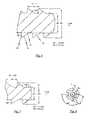
- FIGS. 1 to 4The following is with reference to the FIGS. 1 to 4 as well as referring to the FIGS. 5 to 8 the respective bone screws described which in the medical Device according to the first and second preferred embodiment are used.
- the medical device for positioning the long bones of adjacent first and second phalanges of a patient in the correction positioncomprises a double-threaded bone screw 1, wherein in the inserted (implanted) state of the bone screw 1, the bone screw longitudinal axis coincides with the toe longitudinal axis M of the treated toe of the patient.
- the double-threaded bone screw 1has a substantially cylindrical proximal end portion 10, a substantially cylindrical distal end portion 30, and a substantially cylindrical center portion 20 disposed between the proximal and distal end portions 10, 30.
- These respective sections 10, 20 and 30are each formed as a thread-free circular cylinder.
- a proximal threaded portion 11 having a first thread 11 'and between the distal end portion 30 and the center portion 20a distal threaded portion 31 with a second thread 31 is provided.
- the first thread 11 'has a thread pitch S1 which is smaller than the thread pitch S2 of the second thread 31'.
- the bone screw 1which is used in the medical device according to the first preferred embodiment, further comprises at the proximal end of the proximal end portion 10 a means 40 for receiving a tool for screwing the bone screw 1 into the respective long bones of the first and second toes of the patient on.
- this deviceis executed in the bone screw 1 according to the first preferred embodiment as a screw head, which is designed to receive a Phillips screwdriver.
- the total length of the lies in Fig. 1a to 1cshown bone screw 1 including the device 40 for receiving the tool at 40 mm. Furthermore, it can be seen from the figures that the nominal diameter or the core diameter of the first thread 11 'provided in the proximal threaded portion 11 is 2.4 mm or 1.5 mm. On the other hand, the nominal diameter of the second thread 31 'in the distal thread portion 31 is 1.6 mm, while the core diameter thereof is 1.5 mm.
- the proximal end portion 10has a diameter of 1.6 mm and the distal end portion 30 has a diameter of 1.5 mm, while the proximal end portion 10 has a length of 13 mm and the distal end portion 30 has a length of 4 mm.
- the proximal threaded portion 11 and the distal threaded portion 31each have a length of 4 and 10 mm, respectively.
- Fig. 2 and the Fig. 3shows that in a sectional view along the bone screw longitudinal axis M, the thread 11 'of the proximal threaded portion 11 thread teeth 13 having a first thread profile, and that in a sectional view along the bone screw longitudinal axis M, the thread 31' of the distal threaded portion 31 thread teeth 33 with a to the first thread profile having identical second thread profile.
- both threaded profilesare substantially triangular with rounded edges, wherein the screw-threaded side 14 of the thread profile of a thread tooth 13, 33 with the base 15 of the thread profile forms an angle of about 36 °, and wherein the proximal end portion 10 of the bone screw 1 facing Threaded edge 16 of the thread profile of a thread tooth 13, 33 with the base 15 of the thread profile forms an angle of about 52 °.
- FIG. 5 to Fig. 8shown bone screw 1 according to the second preferred embodiment of the medical device according to the invention is in principle identical to that with reference to Fig. 1 to Fig. 4 described first embodiment. However, there are certain differences in the respective dimensioning of the individual sections of the bone screws, as with reference to the following Table 1 listed characteristics of the bone screw according to the first and second preferred embodiment can be seen.
- the bone screw 1 according to the second embodimentdiffers from the embodiment of the device 40 for receiving a tool for screwing the bone screw 1 into the respective long bones of the first and second toes of the patient.
- this device 40is designed in the form of a pin attached to the screw head, which is engageable with the tool for screwing the bone screw 1 can be brought.
- Fig. 6 and Fig. 7are the respective threads of the proximal and distal threaded portion of in Fig. 5a to 5c shown bone screw 1 according to the second embodiment.
- the comparison of Fig. 6 and the Fig. 7 with the Fig. 2 and the Fig. 3shows that in both embodiments, the thread profiles are identical.
- Fig. 8is a plan view of the distal end of the distal end portion of FIG Fig. 5a to 5c shown bone screw 1 shown.
Landscapes
- Health & Medical Sciences (AREA)
- Orthopedic Medicine & Surgery (AREA)
- Surgery (AREA)
- Life Sciences & Earth Sciences (AREA)
- Heart & Thoracic Surgery (AREA)
- Nuclear Medicine, Radiotherapy & Molecular Imaging (AREA)
- Engineering & Computer Science (AREA)
- Biomedical Technology (AREA)
- Neurology (AREA)
- Medical Informatics (AREA)
- Molecular Biology (AREA)
- Animal Behavior & Ethology (AREA)
- General Health & Medical Sciences (AREA)
- Public Health (AREA)
- Veterinary Medicine (AREA)
- Surgical Instruments (AREA)
Description
Translated fromGermanDie vorliegende Erfindung betrifft eine Vorrichtung zum Positionieren der Röhrenknochen benachbarter erster und zweiter Zehenglieder eines Patienten auf der Zehenlängsachse, wobei die Vorrichtung eine zweigängige Knochenschraube mit einem im wesentlichen zylindrischen proximalen Endabschnitt, einem im wesentlichen zylindrischen distalen Endabschnitt und mit einem zwischen dem proximalen und distalen Endabschnitt angeordneten und im wesentlichen zylindrischen Mittenabschnitt aufweist, wobei zwischen dem proximalen Endabschnitt und dem Mittenabschnitt der Knochenschraube ein proximaler Gewindeabschnitt mit einem ersten Gewinde und zwischen dem distalen Endabschnitt und dem Mittenabschnitt der Knochenschraube ein distaler Gewindeabschnitt mit einem zweiten Gewinde vorgesehen sind, und wobei das erste Gewinde eine Gewindesteigung aufweist, die kleiner als die Gewindesteigung des zweiten Gewindes ist. Es wird auch die Verwendung einer derartigen Vorrichtung offenbart als Einrichtung zum Positionieren der Röhrenknochen von zwei benachbarten Zehengliedern eines Patienten in einer Korrekturstellung auf einer Zehenlängsachse und zum gleichzeitigen Aufbringen einer in Richtung der Zehenlängsachse auf die Röhrenknochen der benachbarten Zehenglieder wirkenden einstellbaren Druckspannung bei der operativen Behandlung eines Hammerzehs oder eines Krallenzehs, oder bei der operativen Behandlung eines Hallux Valgus oder eines Hallux Rigidus, bei welcher jeweils eine resektiosarthroplastische Operationstechnik zum Einsatz kommt.The present invention relates to a device for positioning the tubular bones of adjacent first and second toes of a patient on the longitudinal axis of the toe, the device comprising a bifurcated bone screw having a substantially cylindrical proximal end portion, a substantially cylindrical distal end portion and one intermediate the proximal and distal end portions arranged and substantially cylindrical central portion, wherein between the proximal end portion and the central portion of the bone screw, a proximal threaded portion having a first thread and between the distal end portion and the central portion of the bone screw, a threaded distal portion with a second thread, and wherein the first thread has a pitch that is smaller than the thread pitch of the second thread. The use of such a device is also disclosed as means for positioning the tubular bones of two adjacent toe members of a patient in a correction position on a toe longitudinal axis and simultaneously applying an adjustable compressive stress acting in the direction of the toe longitudinal axis on the long bones of the adjacent phalanges in the operative treatment of a Hammerzehs or a claw toes, or in the operative treatment of a hallux valgus or a hallux rigidus, in each of which a resectio-arthroplastic surgical technique is used.
Die Verwendung von zweigängigen Knochenschrauben ist aus der Medizintechnik im Zusammenhang mit der Behandlung von Kahnbeinfrakturen (Skaphoidfrakturen) bekannt. Beispielsweise werden in den Druckschriften
Die aus dem Stand der Technik bekannte Kompressionsschraube erfordert eine Eröffnung der Handgelenkkapsel, gegebenenfalls eine Reposition und anschließend die Kompression mit einem Zielgerät, dem so genannten "Jig". Das Schraubsystem dient dabei zum Stabilisieren des mit einer Fraktur versehenen Kahnbeinknochens, wobei die Schraube vollständig im Knochen versenkt und nicht wieder entfernt werden kann. Demnach dient das aus der Handchirurgie bekannte Schraubsystem als Kompressionsschraube zur Knochenbruchheilung, wobei zwei Knochenfragmente durch das Einbringen des Schraubsystems dauerhaft zusammengepresst werden.The known from the prior art compression screw requires an opening of the wrist capsule, possibly a reduction and then the compression with a target device, the so-called "jig". The screw system serves to stabilize the provided with a fractured scaphoid bone, the screw completely sunk in the bone and can not be removed again. Accordingly, the known from the hand surgery screwing serves as a compression screw for bone fracture healing, wherein two bone fragments are permanently compressed by the introduction of the screw system.
Bei dieser aus dem Stand der Technik bekannten Kompressionsschraube handelt es sich allerdings um eine Knochenschraube, die speziell für die nicht-konservative Therapie von Skaphoidfrakturen in der Handchirurgie entwickelt wurde, wobei die Knochenschraube ausgelegt ist, die zu verbindenden Knochenbruchstücke des Kahnbeins fest aneinander zu drücken.However, this known from the prior art compression screw is a bone screw, which was specially developed for the non-conservative therapy of scaphoid fractures in hand surgery, wherein the bone screw is designed to firmly press the bone fragments to be connected of the scaphoid.
Die Verwendung einer derartigen Kompressionsschraube zum Positionieren der Röhrenknochen benachbarter erster und zweiter Zehenglieder eines Patienten in einer Korrekturstellung auf einer Zehenlängsachse und zum gleichzeitigen Aufbringen einer in Richtung der Zehenlängsachse auf die Röhrenknochen der benachbarten Zehenglieder wirkenden, genau einstellbaren Druckspannung bei der operativen Behandlung von beispielsweise einem Hammerzeh oder einem Krallenzeh, ist derzeit nicht möglich, da die aus dem Gebiet der Handchirurgie bekannte Kompressionsschraube in struktureller Hinsicht nicht ausgelegt ist, einerseits zwei Knochen, die üblicherweise über ein Gelenk miteinander verbunden sind, nach einem resektiosarthroplastischen Eingriff in einer Korrekturstellung zu positionieren, während andererseits gleichzeitig auf den Knochen eine genau einzustellende leichte Spannung auszuüben ist.The use of such a compression screw for positioning the tubular bones of adjacent first and second toes of a patient in a correction position on a toe longitudinal axis and for simultaneously applying a direction in the direction of the toe longitudinal axis on the tubular bone of the adjacent toe members, precisely adjustable compressive stress in the operative treatment of, for example, a hammer toe or a claw toe, is currently not possible because the compression screw known from the field of hand surgery is structurally incapable of, on the one hand, positioning two bones, which are usually connected to each other via a joint, in a corrective position after a resectional arthroplasty procedure At the same time, it is necessary to exert a slight tension to be set on the bones.
Bei der operativen Behandlung von beispielsweise einem Hammerzeh oder einem Krallenzeh sind allerdings die möglichst genaue Positionierung der Röhrenknochen benachbarter erster und zweiter Zehenglieder in einer Korrekturstellung auf der Zehenlängsachse und das gleichzeitige Aufbringen einer in Richtung der Zehenlängsachse auf die Röhrenknochen wirkenden, genau dosierbaren Druckspannung wesentliche Maßnahmen, die im Hinblick auf eine erfolgreiche Rekonstruktion der behandelten Zehe und im Hinblick auf die Wiederherstellung eines voll belastbaren Fußes ausschlaggebend sind.In the surgical treatment of, for example, a hammer toe or a claw toe, however, the most accurate possible positioning of the long bones of adjacent first and second phalanges in a correction position on the toe axis and the simultaneous application of an acting in the direction of the toe longitudinal axis of the long bones, precisely metered compressive stress essential measures that are crucial in terms of successful reconstruction of the treated toe and in terms of the restoration of a fully resilient foot.
Hammerzehen und Krallenzehen sind Zehenfehlstellungen, die oft zusammen mit einem Hallux Valgus und einem Spreizfuß auftreten. Bei einem Hammerzeh handelt es sich um eine isolierte maximale Beugung der betroffenen Zehe im Endgelenk, während sich Krallenzehen durch eine Überstreckung des Grundgelenkes bei gebeugtem Mittel- und Zehenendgelenk auszeichnen. Da selbst recht ausgeprägte Fehlstellungen häufig sehr schmerzarm sind, die die Lebensqualität des Patienten nicht wesentlich einschränken, ist in vielen Fällen eine operative Behandlung bei einer Hammerzehen-Fehlstellung oder einer Krallenzehen-Fehlstellung aus rein kosmetischen Gründen erforderlich.Hammer toes and claw toes are toe deformities that often occur with a hallux valgus and a splayfoot. In a hammer toe is an isolated maximum flexion of the affected toe in the end joint, while claw toes are characterized by an overstretching of the metacarpophalangeal joint in flexed central and toe end joint. Since even very pronounced malpositions are often very painless, which does not significantly limit the quality of life of the patient, in many cases, an operative treatment in a hock-malalignment or a claw toe deformity for purely cosmetic reasons is required.
Andererseits kann die mit einem Hammerzeh bzw. Krallenzeh einhergehende Fußverformung auch dazu führen, dass beim Patienten die fehlstehenden Zehen am Schuh drücken, wodurch mechanische Reizzustände mit Schwielenbildung (Hühneraugen) und oft auch Entzündungen und chronische Schmerzen entstehen können.On the other hand, the resulting foot deformity with a hammer toe or claw toe can also cause the patient to press the missing toes on the shoe, which can cause mechanical irritation with calluses (corns) and often also inflammation and chronic pain.
Das Ziel der operativen Behandlung einer derartigen Zehenfehlstellung ist die Korrektur der Fehlstellung und der gegebenenfalls bereits eingetretenen Versteifung, sowie die Entlastung der passiven Sehnenspannung durch eine Verkürzung der Knochenstrecke. Hierbei wird beispielsweise mit einer sogenannten "Operation nach Hohmann" ein Teil des Zehenknochens entfernt. Bei dieser Operation wird üblicherweise bei dem nach oben vorspringenden Köpfchen des Grundzehenknochens eine Resektion (Entfernung) an der Stelle durchgeführt, an der das Hühnerauge bzw. die Schwiele sitzt. Im einzelnen wird insbesondere bei Vorliegen von rigiden Krallen- oder Hammerzehenfehlstellungen während des resektionsarthroplastischen Eingriffes häufig zunächst das Köpfchen des Grundgliedes entfernt, wobei anschließend eine Ausdehnung der verkürzten Beugesehne durch manuelle Korrektur stattfindet.The aim of the operative treatment of such a toe misalignment is the correction of the malposition and the possibly already occurred stiffening, as well as the relief of the passive tendon tension by a shortening of the bone section. In this case, a part of the toe bone is removed, for example, with a so-called "Hohmann operation". In this operation, resection (removal) is usually carried out at the point where the corn-eye or the callus sits in the upwardly projecting head of the base toenail bone. Specifically, especially in the presence of rigid claw or hammer toe deformities during the resection arthroplasty procedure, the head of the base member is often first removed, with subsequent expansion of the shortened flexor tendon by manual correction.
Unabhängig von der bei der Rekonstruktion der behandelten Zehe zum Einsatz kommenden Operationstechnik ist es grundsätzlich erforderlich, nach der Stellungskorrektur der Zehenknochen, die Röhrenknochen der benachbarten Zehenglieder des Patienten zu stabilisieren. Üblicherweise wird hierzu als eine innere Schienung zur Sicherstellung des Korrekturergebnisses ein dünner Draht, wie beispielsweise ein Bohrdraht oder ein sogenannter "Kirschnerdraht", im Verlauf der Zehenlängsachse eingebracht.Regardless of the surgical technique used in the reconstruction of the treated toe, it is generally necessary to stabilize the long bones of the adjacent phalanges of the patient after correcting the position of the toe bones. Usually, for this purpose, a thin wire, such as a drill wire or a so-called "Kirschner wire", is introduced in the course of the toe longitudinal axis as an inner splint to ensure the correction result.
Der dabei zum Einsatz kommende Draht dient allerdings nicht nur als eine innere Schienung zur Sicherstellung des Korrekturergebnisses, sondern auch dazu, die behandelte Zehe unter einer während des Operationseingriffes einzustellenden leichten Spannung in Korrekturstellung zu halten. Diese Maßnahme ist für eine Zeitdauer von etwa 2 Wochen erforderlich, innerhalb welcher die während des operativen Eingriffes absichtlich abgelöste Abduktorensehne an der medialen Seite der Grundphalanx wieder angewachsen ist. Nach dieser Zeit muss der Draht wieder aus den Zehengliedern entfernt werden.However, the wire used in this case serves not only as an inner splint to ensure the correction result, but also to keep the treated toe in correcting position under a light tension to be set during the surgery procedure. This procedure is required for a period of about 2 weeks within which the abductor tendon, intentionally detached during the surgical procedure, has regrown on the medial side of the basal phalanx. After this time, the wire must be removed from the toe links again.
Demnach dient derzeit der bei der operativen Behandlung einer Zehenfehlstellung zum Einsatz kommende Draht zur Sicherung des Korrekturergebnisses und insbesondere zum Halten der Zehen nach dessen bei der operativen Rekonstruktion erfolgten korrekten Einstellung.Accordingly, the wire used in the operative treatment of toe deformity currently serves to secure the correction result and, in particular, to hold the toes according to their correct setting during surgical reconstruction.
Da bei jeder Rekonstruktion die Wiederherstellung eines voll belastbaren Fußes angestrebt wird, ist die korrekte Einstellung der behandelten Zehe bekannterweise der schwierigste Teil der Operation und erfordert eine große und langjährige Erfahrung des behandelnden Chirurgen. Dies gilt insbesondere für das Einbringen des Drahtes in die zu schienenden Röhrenknochen der benachbarten Zehenglieder sowie für das Aufbringen der optimalen (leichten) Spannung, unter welcher die benachbarten Zehenglieder der behandelten Zehe gehalten werden. Insbesondere ist es dabei erforderlich, den Abstand der benachbarten Zehenglieder der behandelten Zehe möglichst genau einzustellen, so dass die behandelte Zehe in ihrer natürlichen (korrigierten) Stellung fixiert wird.As every reconstruction seeks to restore a fully resilient foot, correct adjustment of the treated toe is known to be the most difficult part of the operation and requires a long and extensive experience of the attending surgeon. This is especially true for the insertion of the wire into the shining bones of the adjacent phalanges and for the application of the optimum (slight) tension under which the adjacent toes of the treated toe are held. In particular, it is necessary to adjust the distance of the adjacent toes of the treated toe as closely as possible, so that the treated toe is fixed in its natural (corrected) position.
Der vorliegenden Erfindung liegt nun die Problemstellung zugrunde, dass das Einbringen des Drahtes zum Fixieren des Operationsergebnisses und zum Halten der behandelten Zehe nach erfolgter Stellungskorrektur bei einer operativen Rekonstruktion der Zehe die langjährige Erfahrung des Chirurgen erfordert, und insbesondere relativ zeitaufwendig ist, da mit Hilfe des Drahtes auch die leichte Spannung genau einzustellen ist, unter welcher die benachbarten Zehenglieder der behandelten Zehe gehalten werden müssen. Aus diesem Grund ist die operative Behandlung eines Hammerzehs oder eines Krallenzehs auch relativ kostenaufwendig. Andererseits besteht die Gefahr, dass bei einem nicht optimalen Einbringen des Drahtes die Korrekturstellung der behandelten Zehe nicht ausreichend fixiert wird, infolgedessen die behandelte Zehe selbst nach dessen Rekonstruktion eine Fehlstellung beibehält und die korrekte Einstellung des Fußes nicht erreicht wird.The present invention is based on the problem that the introduction of the wire for fixing the operation result and holding the treated toe after correcting the position in an operative reconstruction of the toe requires the long experience of the surgeon, and in particular relatively time consuming, since with the help of Wire is also to adjust the slight tension exactly, under which the adjacent toes of the treated toe must be kept. For this reason, the surgical treatment of a hammer toe or a claw toe is also relatively expensive. On the other hand, there is a risk that in a non-optimal introduction of the wire, the correction position of the treated toe is not sufficiently fixed, as a result, the treated toe even after its reconstruction maintains a malposition and the correct adjustment of the foot is not achieved.
Ausgehend von dieser Problemstellung liegt der vorliegenden Erfindung demnach die Aufgabe zugrunde, eine medizinische Vorrichtung zum Positionieren der Röhrenknochen benachbarter erster und zweiter Zehenglieder eines Patienten in einer bei einem operativen Eingriff eingestellten Korrekturstellung auf der Zehenlängsachse anzugeben, wobei diese medizinische Vorrichtung während des Operationseingriffes ohne größere Schwierigkeiten und Vorkenntnisse des verantwortlichen Chirurgen in einer behandelten Zehe des Patienten implantierbar ist, so dass ohne größeren Aufwand die korrekte Einstellung der behandelten Zehe auch bei komplexen Rekonstruktionen möglich ist. Insbesondere soll die medizinische Vorrichtung bei einem Routineeingriff in der Zehe des Patienten einsetzbar sein, wobei ohne größeren Aufwand nicht nur die Fixierung der benachbarten Zehenglieder der behandelten Zehe, sondern auch das Einstellen der optimalen, auf die benachbarten Zehenglieder auszuübenden (leichten) Spannung ermöglicht wird.Based on this problem, the present invention is therefore an object of the invention to provide a medical device for positioning the long bones of adjacent first and second phalanges of a patient in a set on a surgical intervention correction position on the toe longitudinal axis, said medical device during the surgical procedure without major difficulties and prior knowledge of the responsible surgeon in a treated toe of the patient is implantable, so that without much effort, the correct adjustment of the treated toe is also possible in complex reconstructions. In particular, the medical device is to be used in a routine procedure in the toe of the patient, without much effort not only the fixation of the adjacent toes of the treated toe, but also the setting of the optimal, to be exerted on the adjacent phalanges (light) tension is made possible.
Diese Aufgabe wird erfindungsgemäß mit einer medizinischen Vorrichtung gelöst, die eine zweigängige Knochenschraube mit einem im wesentlichen zylindrischen proximalen Endabschnitt, einem im wesentlichen zylindrischen distalen Endabschnitt und einem zwischen dem proximalen und distalen Endabschnitt angeordneten und im wesentlichen zylindrischen Mittenabschnitt aufweist, wobei zwischen dem proximalen Endabschnitt und dem Mittenabschnitt der Knochenschraube ein proximaler Gewindeabschnitt mit einem ersten Gewinde und zwischen dem distalen Endabschnitt und dem Mittenabschnitt der Knochenschraube ein distaler Gewindeabschnitt mit einem zweiten Gewinde vorgesehen sind, und wobei das erste Gewinde eine Gewindesteigung aufweist, die kleiner als die Gewindesteigung des zweiten Gewindes ist, und wobei der Nenndurchmesser des ersten Gewindes größer als der Durchmesser des proximalen Endabschnittes und der Nenndurchmesser des zweiten Gewindes größer als der Durchmesser des distalen Endabschnittes und gleich groß wie oder kleiner als der Durchmesser des proximalen Endabschnittes ist, und wobei der proximale Endabschnitt der Knochenschraube wenigstens gleich lang wie der Mittenabschnitt ist. Eine Schraube die diese Merkmale aufweist ist aus der
Unter dem hierin verwendeten Begriff "distaler Endabschnitt der Knochenschraube" ist der vordere Endabschnitt der Knochenschraube zu verstehen, welcher in Einschraubrichtung der Knochenschraube liegt. Demgemäß ist unter dem Begriff "proximaler Endabschnitt" der dem distalen Endabschnitt der Knochenschraube gegenüberliegende Endabschnitt der Knaochenschraube zu verstehen. Bei den übrigen Verwendungen der Begriffe "proximal" und "distal" gilt eine entsprechende Definition.The term "distal end portion of the bone screw" as used herein means the front end portion of the bone screw which is in the screwing direction of the bone screw. Accordingly, the term "proximal end portion" is understood to mean the end portion of the bone screw opposite the distal end portion of the bone screw. For other uses of the terms "proximal" and "distal", a corresponding definition applies.
Bei der erfindungsgemäßen medizinischen Vorrichtung kommt somit eine zweigängige Knochenschraube zum Einsatz, bei welcher durch das Vorsehen des proximalen Endabschnittes, des distalen Endabschnittes und des dazwischen angeordneten Mittenabschnittes die Verwendung dieser Knochenschraube als Einrichtung zum Positionieren der Röhrenknochen benachbarter Zehenglieder einer behandelten Zehe in Korrekturstellung auf der Zehenlängsachse möglich ist. Hierzu dienen insbesondere der distale und proximale Endabschnitt der Knochenschraube zur Festlegung der Korrekturstellung der entsprechenden Röhrenknochen auf der Zehenlängsachse. Dabei liegt im implantierten Zustand der Knochenschraube der distale Endabschnitt und der distale Gewindeabschnitt der Knochenschraube im Inneren des Röhrenknochen des ersten Zehengliedes, während der proximale Endabschnitt und der proximale Gewindeabschnitt der Knochenschraube durch das Innere des Röhrenknochens des zweiten Zehengliedes läuft. Die jeweiligen Gewinde des proximalen und distalen Gewindeabschnittes stehen dabei in einem lösbaren Eingriff mit den entsprechenden Röhrenknochen.The medical device according to the invention thus employs a double-threaded bone screw in which, by providing the proximal end portion, the distal end portion and the middle portion therebetween, the use of this bone screw as a means for positioning the long bones of adjacent toes of a treated toe in correction position on the toe longitudinal axis is possible. In particular, the distal and proximal end sections of the bone screw serve to fix the correction position of the corresponding long bones on the toe longitudinal axis. In the implanted state of the bone screw, the distal end section and the distal threaded section of the bone screw lie inside the long bone of the first toe link while the proximal end section and the proximal threaded section of the bone screw pass through the interior of the tubular bone of the second toe link. The respective threads of the proximal and distal threaded portions are in releasable engagement with the corresponding long bones.
Indem für den Nenndurchmesser des ersten Gewindes ein Wert gewählt wird, der größer als der Durchmesser des proximalen Endabschnittes ist, und indem zusätzlich für den Nenndurchmesser des zweiten Gewindes ein Wert gewählt wird, der größer als der Durchmesser des distalen Endabschnittes und gleich groß wie oder kleiner als der Durchmesser des proximalen Endabschnittes der Knochenschraube ist, kann erreicht werden, dass vor dem Einbringen der Knochenschraube in die zu fixierende Zehe des Patienten ein Bohrloch in die Röhrenknochen der benachbarten ersten und zweiten Zehenglieder der behandelten Zehe eingebracht werden kann, welches vorzugsweise längs der Zehenlängsachse verläuft, wobei anschließend beim Einbringen (Einschrauben) der Knochenschraube diese Bohrung mit dem ersten und zweiten Gewinde der Knochenschraube überbohrt wird. Dadurch können die benachbarten Röhrenknochen der ersten und zweiten Zehenglieder der behandelten Zehe mit Hilfe der Knochenschraube in einer idealen Ausrichtung zueinander auf der Zehenlängsachse positioniert werden.By choosing a value for the nominal diameter of the first thread that is greater than the diameter of the proximal end portion, and additionally selecting a value greater than the diameter of the distal end portion and equal to or smaller than the nominal diameter of the second thread As the diameter of the proximal end portion of the bone screw is, it can be achieved that a borehole can be introduced into the long bones of the adjacent first and second toes of the treated toe, preferably along the longitudinal axis of the toe, before inserting the bone screw into the patient's toe to be fixed runs, and then during insertion (screwing) of the bone screw, this hole is overdrilled with the first and second threads of the bone screw. Thereby, the adjacent long bones of the first and second toes of the treated toe can be positioned with the aid of the bone screw in an ideal alignment with one another on the toe longitudinal axis.
Da erfindungsgemäß das erste Gewinde eine Gewindesteigung aufweist, die kleiner als die Gewindesteigung des zweiten Gewindes ist, werden durch eine Drehung der bereits eingesetzten Knochenschraube die beiden benachbarten Zehenglieder der behandelten Zehe relativ zueinander aufeinander zubewegt, da mit dem ersten Gewinde des proximalen Gewindeabschnittes auf den Röhrenknochen des zugehörigen Zehengliedes in Zehenlängsachse (je nach Drehung der Knochenschraube) eine Zug- bzw. Druckspannung ausgeübt wird, deren Betrag verschieden von der Zug- bzw. Druckspannung ist, die über das zweite Gewinde des distalen Gewindeabschnittes auf den Röhrenknochen des benachbarten Zehengliedes ausgeübt wird. Dadurch, dass zwischen dem proximalen und distalen Gewindeabschnitt ein Mittenabschnitt mit einem definierten Abstand vorgesehen ist, infolgedessen das erste und zweite Gewinde der Knochenschraube voneinander definiert beabstandet sind, kann durch eine entsprechende Drehung der Knochenschraube der Abstand zwischen dem ersten und dem benachbarten zweiten Zehenglied der behandelten Zehe sehr genau eingestellt werden.Since, according to the invention, the first thread has a thread pitch which is smaller than the thread pitch of the second thread, the two adjacent toe links of the treated toe are moved toward one another relative to one another by rotation of the bone screw already inserted, since the first thread of the proximal thread section bears on the long bones the toe longitudinal axis (depending on the rotation of the bone screw) a tensile or compressive stress is exerted, the amount of which is different from the tensile or compressive stress on the second thread of the distal threaded portion on the tubular bone of the adjacent Phalanx is exercised. Characterized in that between the proximal and distal threaded portion a central portion is provided at a defined distance, as a result, the first and second threads of the bone screw are defined spaced from each other, by a corresponding rotation of the bone screw, the distance between the first and the adjacent second toe member of the treated Toe to be set very accurately.
Somit ist die medizinische Vorrichtung gemäß der vorliegenden Erfindung, welche die zweigängige Knochenschraube aufweist, einerseits zum Positionieren der Röhrenknochen benachbarter Zehenglieder einer behandelten Zehe in der Korrekturstellung auf der Zehenlängsachse und andererseits zum gleichzeitigen (genauen) Einstellen eines vorgebbaren Abstandes zwischen den benachbarten Zehengliedern geeignet.Thus, the medical device according to the present invention comprising the double-threaded bone screw is suitable, on the one hand, for positioning the long bones of adjacent toe links of a treated toe in the correction position on the toe longitudinal axis and, on the other hand, for simultaneously setting a predeterminable distance between the adjacent toe links.
Insbesondere kann, indem der Abstand zwischen den benachbarten Zehengliedern der behandelten Zehe entsprechend verringert wird, auf die Röhrenknochen der benachbarten Zehenglieder eine genau einstellbare (leichte) Spannung in Richtung der Zehenlängsachse aufgebracht werden, was für eine korrekte Einstellung der behandelten Zehe, insbesondere bei komplexen Rekonstruktionen, erforderlich ist.In particular, by correspondingly reducing the distance between the adjacent toe members of the treated toe, an accurately adjustable (slight) tension in the direction of the toe longitudinal axis can be applied to the long bones of the adjacent toe members, allowing for correct adjustment of the treated toe, particularly in complex reconstructions , is required.
Vorteilhafte Ausführungsformen der erfindungsgemäßen Vorrichtung sind in den Unteransprüchen angegeben.Advantageous embodiments of the device according to the invention are specified in the subclaims.
In einer bevorzugten Realisierung der bei der erfindungsgemäßen Vorrichtung zum Einsatz kommenden Knochenschraube ist vorgesehen, dass der proximale Endabschnitt, der distale Endabschnitt und der Mittenabschnitt zwischen dem proximalen und distalen Endabschnitt der Knochenschraube jeweils als gewindefreie Kreiszylinder ausgebildet sind. Dies ist insbesondere im Hinblick auf das mit der medizinischen Vorrichtung bewirkte Aufbringen einer leichten, genau einstellbaren Spannung auf die benachbarten Zehenglieder der behandelten Zehe von Vorteil. Wie bereits erwähnt, dient dabei der als gewindefreie Kreiszylinder ausgebildete distale Endabschnitt der Knochenschraube zum Positionieren der Knochenschraube längs der Zehenlängsachse, was das Fixieren der benachbarten Zehenglieder der behandelten Zehe in der Korrekturstellung erleichtert. Andererseits dient der gewindefreie Mittenabschnitt dazu, den Abstand und somit auch die Druckspannung zwischen den benachbarten Zehengliedern der behandelten Zehe einzustellen.In a preferred realization of the bone screw used in the device according to the invention, it is provided that the proximal end section, the distal end section and the middle section between the proximal and distal end sections of the bone screw are each designed as thread-free circular cylinders. This is particularly advantageous in view of the application of a slight, precisely adjustable tension to the adjacent toes of the treated toe caused by the medical device. As already mentioned, the distal end section of the bone screw designed as a thread-free circular cylinder serves for positioning the bone screw along the longitudinal axis of the toe, which facilitates the fixing of the adjacent toes of the treated toe in the correction position. On the other hand, the thread-free center section serves to adjust the distance and thus also the compressive stress between the adjacent toes of the treated toe.
Um zu erreichen, dass die erfindungsgemäße medizinische Vorrichtung besonders einfach in den Körper des Patienten implantier- und explantierbar ist, weist die Knochenschraube bevorzugt am proximalen Ende ihres proximalen Endabschnittes ferner eine Einrichtung zur Aufnahme eines Werkzeuges zum Eindrehen der Knochenschraube in die jeweiligen Röhrenknochen der ersten und zweiten Zehenglieder des Patienten auf. Dabei ist bevorzugt der proximale Endabschnitt der Knochenschraube wenigstens gleich lang wie der Mittenabschnitt der Knochenschraube ausgeführt, so dass die Knochenschraube, ausgehend von der Zehenspitze, in die Röhrenknochen der jeweiligen Zehenglieder der behandelten Zehe einführbar ist. Im implantierten Zustand kann dabei die Einrichtung zur Aufnahme des Werkzeuges über das zehenspitzenseitige Ende des Röhrenknochens des zehenspitzenseitigen Zehengliedes hervorstehen, was Vorteile für eine leichte Explantation der Knochenschraube nach der Verheilung der behandelten Zehe mit sich bringt.In order to achieve that the medical device according to the invention is particularly easy implantable and explantable in the body of the patient, the bone screw preferably at the proximal end of its proximal end portion further comprises means for receiving a tool for screwing the bone screw into the respective long bones of the first and second phalanges of the patient. In this case, the proximal end section of the bone screw is preferably designed to be at least as long as the middle section of the bone screw, so that the bone screw, starting from the tip of the toe, can be inserted into the long bones of the respective toes of the treated toe. In the implanted state, the device for receiving the tool can project beyond the toe-tip-side end of the long bone of the toe-tip phalanx, which brings with it advantages for easy explantation of the bone screw after the healing of the treated toe.
Im Hinblick auf die Dimensionierung der Knochenschraube der erfindungsgemäßen medizinischen Vorrichtung ist bevorzugt vorgesehen, dass diese einschließlich der Einrichtung zur Aufnahme des Werkzeuges eine Gesamtlänge aufweist, die in einem Bereich zwischen 43 mm bis 45 mm, und vorzugsweise bei 44 mm liegt. Hierbei handelt es sich um Werte, die im Hinblick auf die Größe der Röhrenknochen benachbarter Zehenglieder eines ausgewachsenen Patienten ausgelegt sind.With regard to the dimensioning of the bone screw of the medical device according to the invention, it is preferably provided that this, including the device for receiving the tool, has an overall length which lies in a range between 43 mm to 45 mm, and preferably 44 mm. These are values designed for the size of the long bones of adjacent toes of a full-grown patient.
Andererseits wurde herausgefunden, dass mit der erfindungsgemäßen medizinischen Vorrichtung nicht nur eine optimale Einstellung der auf die benachbarten Zehenglieder auszuübenden leichten Spannung möglich ist, sondern auch ein optimaler Abstand zwischen den Röhrenknochen der benachbarten Zehenglieder leicht einstellbar ist, wenn der Nenndurchmesser des Gewindes des proximalen Gewindeabschnittes in einem Bereich zwischen 2,3 mm bis 2,8 mm, und vorzugsweise bei 2,7 mm liegt, und wenn der Nenndurchmesser des Gewindes des distalen Gewindeabschnittes in einem Bereich zwischen 1,4 mm bis 2,5 mm, und vorzugsweise bei 2,4 mm liegt. Bei diesen für die jeweiligen Nenndurchmesser geltenden Werten kann einerseits ein sicherer Eingriff der jeweiligen Gewinde des distalen bzw. proximalen Gewindeabschnittes mit dem Röhrenknochen des zugehörigen Zehengliedes sichergestellt werden, während gleichzeitig die einfache und problemlose Rückholbarkeit der Knochenschraube ermöglich wird.On the other hand, it has been found that with the medical device according to the invention not only is it possible to optimally adjust the slight tension to be applied to the adjacent toes, but also that an optimum distance between the long bones of the adjacent toes is easily adjustable when the nominal diameter of the thread of the proximal threaded section is in a range between 2.3 mm to 2.8 mm, and preferably 2.7 mm, and when the nominal diameter of the thread of the distal thread section is in a range between 1.4 mm to 2.5 mm, and preferably at 2, 4 mm. On the one hand, these values, which are valid for the respective nominal diameters, ensure a secure engagement of the respective threads of the distal or proximal threaded section with the long bone of the associated phalanx, while at the same time enabling easy and problem-free retrievability of the bone screw.
Da die Knochenschraube der medizinischen Vorrichtung ausgelegt ist, durch Überbohrung von beispielsweise einem in die jeweiligen Röhrenknochen eingebrachten Bohrloch implantierbar zu sein, ist es bevorzugt, dass die jeweiligen Gewinde des proximalen und distalen Gewindeabschnittes als selbstschneidende Gewinde ausgeführt sind. Da beim Implantieren der Knochenschraube das Gewinde des proximalen Gewindeabschnittes mit dem Röhrenknochen desjenigen Zehengliedes in Eingriff zu bringen ist, durch dessen Röhrenknochen bereits das Gewinde des distalen Gewindeabschnittes der Knochenschraube durchgelaufen ist, ist es im Hinblick auf eine sichere und feste Fixierung der Knochenschraube bevorzugt, dass das Gewinde des proximalen Gewindeabschnittes einen Kerndurchmesser aufweist, der größer als der Kerndurchmesser des Gewindes des distalen Gewindeabschnittes ist.Since the bone screw of the medical device is designed to be implantable by over-drilling, for example, a borehole inserted into the respective long bones, it is preferable that the respective threads of the proximal and distal threaded sections are made as self-tapping threads. Since the Implanting the bone screw, the thread of the proximal threaded portion is to be engaged with the long bone of that toe member through the long bone of the threaded portion of the bone screw has already passed, it is preferable for a secure and firm fixation of the bone screw that the thread of the proximal threaded portion has a core diameter larger than the core diameter of the thread of the distal threaded portion.
In einer besonders bevorzugten Realisierung, insbesondere im Hinblick auf die Anwendung der medizinischen Vorrichtung zum Positionieren der Röhrenknochen benachbarter Zehenglieder einer operativ behandelten Zehe in der Korrekturstellung auf der Zehenlängsachse, ist vorgesehen, dass der Kerndurchmesser des Gewindes des proximalen Gewindeabschnittes in einem Bereich zwischen 1,4 mm bis 1,9 mm, und vorzugsweise bei 1,8 mm liegt, und dass der Kerndurchmesser des Gewindes des distalen Gewindeabschnittes in einem Bereich zwischen 0,9 mm bis 1,5 mm, und vorzugsweise bei 1,4 mm liegt. Hierbei handelt es sich um Größenangaben, bei denen eine möglichst optimale Einstellung der behandelten Zehe insbesondere bei einer komplexen Rekonstruktion möglich ist.In a particularly preferred realization, in particular with regard to the use of the medical device for positioning the tubular bones of adjacent toes of an operatively treated toe in the correction position on the toe longitudinal axis, it is provided that the core diameter of the thread of the proximal threaded section is in a range between 1.4 mm to 1.9 mm, and preferably 1.8 mm, and that the core diameter of the thread of the distal thread section is in a range between 0.9 mm to 1.5 mm, and preferably 1.4 mm. These are size indications in which the best possible adjustment of the treated toe is possible, especially in a complex reconstruction.
Bei einer erfindungsgemäßen Lösung ist der Durchmesser des proximalen Endabschnittes der Knochenschraube größer als der Durchmesser des distalen Endabschnittes der Knochenschraube, wobei in einer bevorzugten Realisierung der Knochenschraube der Durchmesser des proximalen Endabschnittes vorzugsweise in einem Bereich zwischen 1,5 mm bis 1,9 mm und noch bevorzugter bei 1,8 mm liegt, und wobei der Durchmesser des distalen Endabschnittes der Knochenschraube vorzugsweise in einem Bereich zwischen 1,3 mm und 1,6 mm, und noch bevorzugter bei 1,4 mm liegt. Diese Werte sind im Hinblick auf die Größe der zu stabilisierenden Röhrenknochen der Zehenglieder gewählt, wobei als Maß hierzu ein durchschnittlicher (erwachsener) Patient angenommen wurde. Selbstverständlich ist es aber auch denkbar, dass diese Größenwerte abhängig von der Größe des Patienten bzw. der Größe der Röhrenknochen der behandelten Zehe variiert werden.In a solution according to the invention, the diameter of the proximal end portion of the bone screw is greater than the diameter of the distal end portion of the bone screw, wherein in a preferred realization of the bone screw, the diameter of the proximal end portion preferably in a range between 1.5 mm to 1.9 mm and still more preferably 1.8 mm, and wherein the diameter of the distal end portion of the bone screw is preferably in a range between 1.3 mm and 1.6 mm, and more preferably 1.4 mm. These values are selected in view of the size of the tubular bones of the phalanges to be stabilized, with the average adult patient being taken as the measure. Of course, it is also conceivable that these size values are varied depending on the size of the patient or the size of the long bones of the treated toe.
Um zu erreichen, dass die Knochenschraube der erfindungsgemäßen medizinischen Vorrichtung im implantierten Zustand das zugehörige überbohrte Bohrloch hinreichend abdichtet, ist in einer bevorzugten Weiterentwicklung der erfindungsgemäßen Vorrichtung vorgesehen, dass der Durchmesser des proximalen Endabschnittes der Knochenschraube identisch mit dem Kerndurchmesser des Gewindes des proximalen Endabschnittes ist und vorzugsweise in einem Bereich zwischen 1,5 mm bis 1,9 mm, und noch bevorzugter bei 1,8 mm liegt. Andererseits sollte der Durchmesser des distalen Endabschnittes der Knochenschraube größer als oder gleich groß wie der Kerndurchmesser des Gewindes des distalen Gewindeabschnittes sein und vorzugsweise in einem Bereich zwischen 1,3 mm und 1,6 mm, und noch bevorzugter bei 1,4 mm liegen.In order to ensure that the bone screw of the medical device according to the invention in the implanted state sufficiently seals the associated drilled hole, in a preferred development of the device according to the invention, the diameter of the proximal end section of the bone screw is identical to the core diameter of the thread of the proximal end section is and is preferably in a range between 1.5 mm to 1.9 mm, and more preferably 1.8 mm. On the other hand, the diameter of the distal end portion of the bone screw should be greater than or equal to the core diameter of the thread of the distal threaded portion and preferably in a range between 1.3 mm and 1.6 mm, and more preferably 1.4 mm.
Im Hinblick auf eine möglichst genaue Einstellbarkeit des Abstandes zwischen den in Korrekturstellung vorliegenden Röhrenknochen der benachbarten Zehenglieder ist vorgesehen, dass das Gewinde des proximalen Gewindeabschnittes der Knochenschraube eine Gewindesteigung aufweist, die in einem Bereich zwischen 0,9 bis 1,1, und vorzugsweise bei 1,0 liegt, wobei das Gewinde des distalen Gewindeabschnittes eine Gewindesteigung aufweist, die in einem Bereich zwischen 1,03 bis 1,35 und vorzugsweise in einem Bereich zwischen 1,15 und 1,35, und noch bevorzugter bei 1,25 liegt. Darüber hinaus sollten im Gewinde des proximalen Gewindeabschnittes der Knochenschraube insgesamt etwa 8 oder 9 jeweils gleichweit voneinander beabstandete Gewindegänge vorgesehen sein, wobei im Gewinde des distalen Gewindeabschnittes der Knochenschraube insgesamt etwa 4 jeweils gleichweit voneinander beabstandete Gewindegänge vorgesehen sind. Diese Kennwerte für die jeweiligen Gewinde des proximalen und distalen Gewindeabschnittes ermöglichen eine optimale Einstellung der Spannung zwischen den benachbarten Zehengliedern der behandelten Zehe. Insbesondere kann durch eine leichte Drehung der implantierten Knochenschraube diese Spannung entsprechend erhöht oder verringert werden. Auf diese Weise kann ohne größeres Geschick des Chirurgen die Korrekturstellung der behandelten Zehe sichergestellt werden, wobei gleichzeitig die Zehenglieder im Hinblick auf die Verheilung der behandelten Zehe in einem optimalen Zustand vorliegen.With regard to the most accurate adjustability of the distance between the present in correction position long bones of the adjacent toe links is provided that the thread of the proximal threaded portion of the bone screw has a thread pitch which is in a range between 0.9 to 1.1, and preferably at 1 0, the thread of the distal threaded portion having a pitch ranging from 1.03 to 1.35, and preferably ranging from 1.15 to 1.35, and more preferably 1.25. In addition, in the thread of the proximal threaded portion of the bone screw a total of about 8 or 9 equidistant spaced threads should be provided, wherein in the thread of the distal threaded portion of the bone screw a total of about four equally spaced apart threads are provided. These characteristics for the respective threads of the proximal and distal threaded sections allow for optimal adjustment of the tension between the adjacent toe members of the treated toe. In particular, this voltage can be correspondingly increased or reduced by a slight rotation of the implanted bone screw. In this way, without any great skill of the surgeon, the correction position of the treated toe can be ensured, while at the same time the toes members are in an optimal state with regard to the healing of the treated toe.
In der erfindungsgemäßen Vorrichtung beträgt die Länge des proximalen Gewindeabschnittes der Knochenschraube 3 mm bis 5 mm, und vorzugsweise 4 mm, die Länge des distalen Gewindeabschnittes der Knochenschraube 9 mm bis 11 mm, und vorzugsweise 10 mm, die Länge des proximalen Endabschnittes der Knochenschraube 12 mm bis 14 mm, und vorzugsweise 13 mm, und die Länge des distalen Endabschnittes der Knochenschraube 3 mm bis 5 mm, wobei der Abstand zwischen dem proximalen und dem distalen Gewindeabschnitt zwischen 11 mm und 13,5 mm, und vorzugsweise 12 mm beträgt.In the device according to the invention, the length of the proximal threaded portion of the bone screw is 3 mm to 5 mm, and preferably 4 mm, the length of the distal threaded portion of the bone screw 9 mm to 11 mm, and preferably 10 mm, the length of the proximal end portion of the
Um zu erreichen, dass bei der erfindungsgemäßen medizinischen Vorrichtung die Knochenschraube ohne größeren operativen Eingriff leicht implantierbar und nach zumindest teilweiser Verheilung der behandelten Zehe wieder explantierbar ist, ist in einer bevorzugten Weiterentwicklung der bei der medizinischen Vorrichtung zum Einsatz kommenden Knochenschraube vorgesehen, dass in einer Schnittansicht längs der Knochenschraubenlängsachse das Gewinde des proximalen Gewindeabschnittes eine Vielzahl von Gewindezähnen mit einem ersten Gewindeprofil aufweist, und dass in einer Schnittansicht längs der Knochenschraubenlängsachse das Gewinde des distalen Gewindeabschnittes eine Vielzahl von Gewindezähnen mit einem zum ersten Gewindeprofil identischen zweiten Gewindeprofil aufweist.In order to ensure that in the medical device according to the invention, the bone screw without major surgery easily implantable and after at least partial healing of the treated toe is explantable again, is in a preferred Further development of the bone screw used in the medical device provided that in a sectional view along the bone screw longitudinal axis, the thread of the proximal threaded portion having a plurality of thread teeth with a first thread profile, and that in a sectional view along the bone screw longitudinal axis, the thread of the distal threaded portion a plurality of Having thread teeth with a first thread profile identical second thread profile.
Dabei sollte das erste Gewindeprofil eine im wesentlichen dreieckige Formgebung vorzugsweise mit abgerundeten Kanten aufweisen, bei welcher die einschraubseitige Gewindeflanke des Gewindeprofils eines Gewindezahnes mit der Basis des Gewindeprofils einen Winkel von 35° bis 37°, und vorzugsweise 36° einschließt, und bei welcher die dem proximalen Endabschnitt der Knochenschraube zugewandte Gewindeflanke des Gewindeprofils des einen Gewindezahns mit der Basis des Gewindeprofils einen Winkel 51° bis 53 °, und vorzugsweise 52° einschließt. Diese Formgebung der jeweiligen Gewindezähne der Gewinde des proximalen und des distalen Gewindeabschnittes der Knochenschraube ermöglichen ein besonders leichtes Implantieren und Explantieren der Knochenschraube einerseits, und einen sicheren Halt der implantierten Knochenschraube im Inneren der Röhrenknochen der behandelten Zehe andererseits, so dass die Knochenschraube als innere Schiene der Zehe dienen kann. Selbstverständlich sind aber auch andere Gewindeprofile denkbar.In this case, the first thread profile should have a substantially triangular shape, preferably with rounded edges, in which the screw-threaded side of the thread profile of a thread tooth with the base of the thread profile forms an angle of 35 ° to 37 °, and preferably 36 °, and in which the proximal end portion of the bone screw facing thread flank of the thread profile of a thread tooth with the base of the thread profile at an angle 51 ° to 53 °, and preferably includes 52 °. This shaping of the respective thread teeth of the threads of the proximal and the distal threaded portion of the bone screw allow a particularly easy implantation and explantation of the bone screw on the one hand, and a secure hold of the implanted bone screw inside the long bones of the treated toe on the other hand, so that the bone screw as the inner rail Can serve toe. Of course, other thread profiles are conceivable.
Schließlich ist im Hinblick auf das verwendete Material der bei der medizinischen Vorrichtung zum Einsatz kommenden Gewindeschraube vorgesehen, dass die Knochenschraube aus Titan oder einer Titanlegierung, insbesondere Nitinol besteht. Diese Materialien sind für Implantate aus der Medizintechnik bekannt, und zeichnen sich zum einen durch ihre gute Körperverträglichkeit und zum anderen durch ihre hervorragenden mechanischen Materialeigenschaften aus.Finally, with regard to the material used, the threaded screw used in the medical device is provided that the bone screw consists of titanium or a titanium alloy, in particular Nitinol. These materials are known for implants in medical technology, and are characterized on the one hand by their good body compatibility and on the other by their excellent mechanical material properties.
Aus dem vorstehend Gesagten ist es ersichtlich, dass sich die beanspruchte medizinische Vorrichtung mit der Knochenschraube insbesondere zur Verwendung als Einrichtung zum Positionierung der Röhrenknochen von zwei benachbarten Zehengliedern eines Patienten in einer Korrekturstellung auf einen Zehenlängsachse und zum gleichzeitigen Aufbringen einer in Richtung der Zehenlängsachse auf die Röhrenknochen der benachbarten Zehenglieder wirkenden, genau einstellbaren Druckspannung eignet. Diese Verwendung ist derzeit nur aus
Aus diesem Grund wird - neben der medizinischen Vorrichtung als solche - auch die Verwendung dieser medizinischen Vorrichtung offenbart, und zwar als Einrichtung zum Positionieren der Röhrenknochen von zwei benachbarten Zehengliedern eines Patienten in einer Korrekturstellung auf der Zehenlängsachse und zum gleichzeitigen Aufbringen einer in Richtung der Zehenlängsachse auf die Röhrenknochen der benachbarten Zehenglieder wirkenden, einstellbaren Druckspannung, vorzugsweise bei der operativen Behandlung von Hammerzehen oder Krallenzehen, bei welcher eine resektionsarthroplastische Operationstechnik zum Einsatz kommt, oder bei der operativen Behandlung eines Hallux Valgus oder eines Hallux Rigidus, bei welcher eine resektionsarthroplastische Operationstechnik zum Einsatz kommt.For this reason, in addition to the medical device as such, the use of this medical device is also disclosed, as a means for positioning the long bones of two adjacent toes of a patient in a corrective position on the toe longitudinal axis and simultaneously applying one in the direction of the toe axis the tubular bones of the adjacent phalanges, adjustable compressive stress, preferably in the operative treatment of hammertoes or claw toes, in which a resection arthroplasty surgical technique is used, or in the operative treatment of a hallux valgus or a hallux rigidus, in which a resection arthroplasty surgical technique is used ,
Selbstverständlich eignet sich die erfindungsgemäße medizinische Vorrichtung auch für andere orthopädische Anwendungsfälle, bei welchen vorübergehend zwei oder mehrere Knochen einer Zehe in einer Korrekturstellung auf der Zehenlängsachse positioniert und fixiert werden müssen.Of course, the medical device according to the invention is also suitable for other orthopedic applications in which temporarily two or more bones of a toe must be positioned and fixed in a correction position on the toe longitudinal axis.
Im folgenden werden bevorzugte Realisierungen der erfindungsgemäßen Vorrichtung anhand der beiliegenden Zeichnungen beschrieben. Hierbei handelt es sich um derzeit bevorzugte Ausführungsformen der in der medizinischen Vorrichtung zum Einsatz kommenden Knochenschraube, die jedoch nicht als eine Einschränkung der beanspruchten medizinischen Vorrichtung zu deuten sind.In the following preferred embodiments of the device according to the invention will be described with reference to the accompanying drawings. These are presently preferred embodiments of the bone screw used in the medical device, but they should not be construed as limiting the claimed medical device.
- Fig. 1aFig. 1a
- eine perspektivische Ansicht einer ersten bevorzugten Ausführungsform der bei der erfindungsgemäßen medizinischen Vorrichtung zum Einsatz kommenden zweigängigen Knochenschraube;a perspective view of a first preferred embodiment of the two-speed bone screw used in the medical device according to the invention;
- Fig. 1bFig. 1b
- eine perspektivische Seitenansicht der Knochenschraube gemäß
Fig. 1a ;a perspective side view of the bone screw according toFig. 1a ; - Fig. 1cFig. 1c
- eine Längsschnittansicht der in
Fig. 1b gezeigten Knochenschraube;a longitudinal sectional view of inFig. 1b shown bone screw; - Fig. 2Fig. 2
- einen vergrößerten Ausschnitt aus der in
Fig. 1c gezeigten Längsschnittdarstellung der bei der medizinischen Vorrichtung gemäß der ersten bevorzugten Ausführungsform zum Einsatz kommenden Knochenschraube, bei welchem der proximale Gewindeabschnitt der Knochenschraube gezeigt ist;an enlarged section of the inFig. 1c shown longitudinal sectional view of the medical device according to the first preferred Embodiment for use coming bone screw, in which the proximal threaded portion of the bone screw is shown; - Fig. 3Fig. 3
- einen vergrößerten Ausschnitt aus der in
Fig. 1c gezeigten Längsschnittdarstellung der bei der medizinischen Vorrichtung gemäß der ersten bevorzugten Ausführungsform zum Einsatz kommenden Knochenschraube, bei welchem der distale Gewindeabschnitt der Knochenschraube gezeigt ist;an enlarged section of the inFig. 3 shows a longitudinal sectional view of the bone screw used in the medical device according to the first preferred embodiment, in which the distal threaded section of the bone screw is shown;1c - Fig. 4Fig. 4
- eine Draufsicht das proximale Ende des proximalen Endabschnittes der bei der bevorzugten ersten Ausführungsform der medizinischen Vorrichtung zum Einsatz kommenden Knochenschraube;a plan view of the proximal end of the proximal end portion of the bone screw used in the preferred first embodiment of the medical device;
- Fig. 5aFig. 5a
- eine perspektivische Ansicht einer zweiten bevorzugten Ausführungsform der bei der erfindungsgemäßen medizinischen Vorrichtung zum Einsatz kommenden zweigängigen Knochenschraube;a perspective view of a second preferred embodiment of the two-speed bone screw used in the medical device according to the invention;
- Fig. 5bFig. 5b
- eine perspektivische Seitenansicht der Knochenschraube gemäß
Fig. 5a ;a perspective side view of the bone screw according toFig. 5a ; - Fig. 5cFig. 5c
- eine Längsschnittansicht der in
Fig. 5b gezeigten Knochenschraube;a longitudinal sectional view of inFig. 5b shown bone screw; - Fig. 6Fig. 6
- einen vergrößerten Ausschnitt aus der in
Fig. 5c gezeigten Längsschnittdarstellung der bei der medizinischen Vorrichtung gemäß der zweiten bevorzugten Ausführungsform zum Einsatz kommenden Knochenschraube, bei welchem der proximale Gewindeabschnitt der Knochenschraube gezeigt ist;an enlarged section of the inFig. 3 shows a longitudinal sectional view of the bone screw used in the medical device according to the second preferred embodiment, in which the proximal threaded portion of the bone screw is shown;5c - Fig. 7Fig. 7
- einen vergrößerten Ausschnitt aus der in
Fig. 5c gezeigten Längsschnittdarstellung der bei der medizinischen Vorrichtung gemäß der zweiten bevorzugten Ausführungsform zum Einsatz kommenden Knochenschraube, bei welchem der distale Gewindeabschnitt der Knochenschraube gezeigt ist; undan enlarged section of the inFig. 3 shows a longitudinal sectional view of the bone screw used in the medical device according to the second preferred embodiment, in which the distal threaded section of the bone screw is shown; and5c - Fig. 8Fig. 8
- eine Draufsicht auf das distale Ende des distalen Endabschnittes der in
Fig. 5b gezeigten Knochenschraube.a plan view of the distal end of the distal end portion of inFig. 5b shown bone screw.
Nachfolgend wird unter Bezugnahme auf die
Wie dargestellt, weist die medizinische Vorrichtung zum Positionieren der Röhrenknochen benachbarter erster und zweiter Zehenglieder eines Patienten in der Korrekturstellung eine zweigängige Knochenschraube 1 auf, wobei im eingesetzten (implantierten) Zustand der Knochenschraube 1 die Knochenschraubenlängsachse mit der Zehenlängsachse M der behandelten Zehe des Patienten übereinstimmt.As shown, the medical device for positioning the long bones of adjacent first and second phalanges of a patient in the correction position comprises a double-threaded
Im einzelnen weist die zweigängige Knochenschraube 1 einen im wesentlichen zylindrischen proximalen Endabschnitt 10, einen im wesentlichen zylindrischen distalen Endabschnitt 30 sowie einen zwischen dem proximalen und distalen Endabschnitt 10, 30 angeordneten und im wesentlichen zylindrischen Mittenabschnitt 20 auf. Diese jeweiligen Abschnitte 10, 20 und 30 sind dabei jeweils als gewindefreie Kreiszylinder ausgebildet.In particular, the double-threaded
Des weiteren ist bei der Knochenschraube 1 zwischen dem proximalen Endabschnitt 10 und dem Mittenabschnitt 20 ein proximaler Gewindeabschnitt 11 mit einem ersten Gewinde 11' und zwischen dem distalen Endabschnitt 30 und dem Mittenabschnitt 20 ein distaler Gewindeabschnitt 31 mit einem zweite Gewinde 31 vorgesehen. Anhand der Figuren zu erkennen, dass das erste Gewinde 11' eine Gewindesteigung S1 aufweist, die kleiner als die Gewindesteigung S2 des zweiten Gewindes 31' ist.Furthermore, in the
Dadurch kann erreicht werden, dass bei Drehung der Knochenschraube 1 um die Knochenschraubenlängsachse M mit den jeweiligen Gewinden 11' und 31' des proximalen und distalen Gewindeabschnittes 11, 31 jeweils Längskräfte erzeugt werden, wobei die mit dem Gewinde 31' des distalen Gewindeabschnitte 31 erzeugte Längskraft größer als die mit dem Gewinde 11' des proximalen Gewindeabschnittes 11 erzeugte Längskraft ist.It can thereby be achieved that upon rotation of the
Die Knochenschraube 1, welche bei der medizinischen Vorrichtung gemäß der ersten bevorzugten Ausführungsform zum Einsatz kommt, weist am proximalen Ende des proximalen Endabschnittes 10 ferner eine Einrichtung 40 zur Aufnahme eines Werkzeuges zum Eindrehen der Knochenschraube 1 in die jeweiligen Röhrenknochen der ersten und zweiten Zehenglieder des Patienten auf. Wie es beispielsweise in
Insgesamt liegt die Gesamtlänge der in
Ferner ist bei der Knochenschraube 1 gemäß
Nachfolgend werden unter Bezugnahme auf
Der Zusammenschau der
Die in
Des weiteren unterscheidet sich die Knochenschraube 1 gemäß der zweiten Ausführungsform durch die Ausführung der Einrichtung 40 zur Aufnahme eines Werkzeuges zum Eindrehen der Knochenschraube 1 in die jeweiligen Röhrenknochen der ersten und zweiten Zehenglieder des Patienten. Wie in den
In
In
Die Erfindung ist nicht auf die in den Figuren gezeigten und speziellen Ausführungsformen beschränkt. Insbesondere können die angegebenen Dimensionierungen und Kenngrößen in Abhängigkeit des jeweiligen Einzelfalls abgeändert werden so weit diese den Ansprüchen unterzuordnen sind.The invention is not limited to those shown in the figures and specific embodiments. In particular, the specified dimensions and characteristics can be changed depending on the particular case as far as they are subordinate to the claims.
- 11
- Knochenschraubebone screw
- 1010
- proximaler Endabschnittproximal end portion
- 1111
- proximaler Gewindeabschnittproximal threaded section
- 11'11 '
- erstes Gewinde/Gewindes des proximalen Gewindeabschnittesfirst thread / thread of the proximal threaded section
- 1313
- Gewindezahn des ersten GewindesThread tooth of the first thread
- 1414
- einschraubseitige Gewindeflankescrew-in thread flank
- 1515
- Gewindezahn-BasisThread tooth base
- 1616
- schraubenkopfseitige Gewindeflankescrew head thread flank
- 2020
- Mittenabschnittmid section
- 2525
- ÜbergangsabschnittTransition section
- 3030
- distaler Endabschnittdistal end portion
- 3131
- distaler Gewindeabschnittdistal threaded section
- 31'31 '
- zweites Gewinde/Gewindes des distalen Gewindeabschnittessecond thread / thread of the distal thread section
- 3333
- Gewindezahn des zweiten GewindesThread tooth of the second thread
- 4040
- Einrichtung zur Aufnahme eines Werkzeuges/SchraubkopfDevice for holding a tool / screw head
- D1D1
- Durchmesser des proximalen EndabschnittesDiameter of the proximal end portion
- D2D2
- Durchmesser des distalen EndabschnittesDiameter of the distal end portion
- Ee
- Einschraubrichtungthe screwing
- K1K1
- Kerndurchmesser des ersten GewindesCore diameter of the first thread
- K2K2
- Kerndurchmesser des zweiten GewindesCore diameter of the second thread
- MM
- Zehenlängsachsetoe longitudinal axis
- N1N1
- Nenndurchmesser des ersten GewindesNominal diameter of the first thread
- N2N2
- Nenndurchmesser des zweiten GewindesNominal diameter of the second thread
Claims (15)
- A device for positioning tubular bones of a patient's neighboring first and second phalanges on the longitudinal axis (M) of the toe, wherein the device comprises a double-threaded bone screw (1) having a substantially cylindrical proximal end section (10), a substantially cylindrical distal end section (30) and a substantially cylindrical central section (20) arranged between the proximal and distal end sections (10, 30), wherein a proximal thread section (11) having a first thread (11') is provided between the proximal end section (10) and the central section (20) of the bone screw (1) and a distal thread section (31) having a second thread (31') is provided between the distal end section (30) and the central section (20) of the bone screw (10), wherein- the first thread (11') has a pitch (S1) which is smaller than the pitch (S2) of the second thread (31');.- the nominal diameter (N1) of the first thread (11') is larger than the diameter (D1) of the proximal end section (10), and wherein the nominal diameter (N2) of the second thread (31') is larger than the diameter (D2) of the distal end section (30) and just as large or smaller than the diameter (D1) of the proximal end section (10), and wherein the proximal end section (10) of the bone screw (1) is at least as long as the central section (20),characterized in that
the thread (11') of the proximal thread section (11) of the bone screw (1) exhibits a pitch in the range of between 0.9 and 1.1, and preferably 1.0, and the thread (31') of the distal thread section (31) exhibits a pitch in the range of between 1.03 and 1.35, and preferably in the range of between 1.15 and 1.35, and is more preferable at 1.25; and that
the proximal thread section (11) of the bone screw (1) has a length of from 3 to 5 mm, and preferably 4 mm, the distal thread section (31) of the bone screw (1) has a length of from 9 to 11 mm, and preferably 10 mm, the proximal end section (10) of the bone screw (1) has a length of from 12 to 14 mm, and preferably 13 mm, and the distal end section (30) of the bone screw (1) has a length of from 3 to 5 mm, and preferably 4 mm, and that the distance between the proximal and the distal thread section (11, 31) is between 11 and 13.5 mm, and preferably 12 mm. - The device according to claim 1, wherein
the proximal end section (10), the distal end section (30) and the central section (20) between the proximal and distal end sections (10, 30) of the bone screw (1) are each respectively configured as unthreaded circular cylinders. - The device according to claim 1 or 2, wherein
a mechanism (40) is further provided on the proximal end of the proximal end section (10) of the bone screw (1) to receive a tool for screwing the bone screw (1) into the respective tubular bones of the patient's first and second phalanges. - The device according to claim 3, wherein
the full length of the bone screw (1) including the mechanism (40) for receiving the tool measures within a range of between 43 and 45 mm, and is preferably 44 mm. - The device according to any one of the preceding claims, wherein
the nominal diameter (N1) of the thread (11') of the proximal thread section (11) is in a range of between 2.3 and 2.8 mm, and is preferably 2.7 mm, and/or wherein the nominal diameter (N2) of the thread (31') of the distal thread section (31) is in a range of between 1.4 and 2.5 mm, and is preferably 2.4 mm. - The device according to any one of the preceding claims, wherein
the thread (11') of the proximal thread section (11) of the bone screw (1) exhibits a core diameter (K1) which is larger than the core diameter (K2) of the thread (31') of the distal thread section (31) of the bone screw (1). - The device according to claim 6, wherein
the core diameter (K1) of the thread (11') of the proximal thread section (11) is in a range of between 1.4 and 1.9 mm, and is preferably 1.8 mm, and/or wherein the core diameter (K2) of the thread (31') of the distal thread section (31) is in a range of between 0.9 and 1.5 mm, and is preferably 1.4 mm. - The device according to any one of the preceding claims, wherein
the diameter (D1) of the proximal end section (10) of the bone screw (1) is larger than the diameter (D2) of the distal end section (30) of the bone screw (1), and wherein the diameter (D1) of the proximal end section (10) is preferably in a range of between 1.5 and 1.9 mm, and is more preferable at 1.8 mm, and wherein the diameter (D2) of the distal end section (30) of the bone screw (1) is preferably in a range of between 1.3 and 1.6 mm, and is more preferable at 1.4 mm. - The device according to any one of the preceding claims, wherein
the diameter (D1) of the proximal end section (10) of the bone screw (1) is identical to the core diameter (K1) of the thread (11') of the proximal thread section (11) of the bone screw and preferably in a range of between 1.5 and 1.9 mm, and is more preferable at 1.8 mm. - The device according to any one of the preceding claims, wherein
the diameter (D2) of the distal end section (30) of the bone screw (1) is larger or just as large as the core diameter (K2) of the thread (31') of the distal thread section (31) of the bone screw (1) and preferably in a range of between 1.3 and 1.6 mm, and is more preferable at 1.4 mm - The device according to any one of the preceding claims, wherein
a total of 8 or 9 thread turns of respectively equal distance from one another are provided in the thread (11') of the proximal thread section (11) of the bone screw (1), and wherein a total of four thread turns of respectively equal distance from one another are provided in the thread (31') of the distal thread section (31) of the bone screw (1). - The device according to any one of the preceding claims, wherein
a transitional section (25) having a cross-sectional tapering shape in the screwing direction (E) of the bone screw (1) is provided between the central section (20) of the bone screw (1) and the proximal thread section (11) of the bone screw (1). - The device according to any one of the preceding claims, wherein
the thread (11') of the proximal thread section (11) exhibits threaded teeth (13) having a first thread profile when viewed sectionally along the bone screw longitudinal axis (M), and wherein the thread (31') of the distal thread section (31) exhibits threaded teeth (33) having a second thread profile identical to the first thread profile when viewed sectionally along the bone screw longitudinal axis (M). - The device according to claim 13, wherein
the first thread profile exhibits a substantially triangular shape, preferably with rounded edges, in which the screwing-side thread flank (14) of the thread profile of a threaded tooth (13) forms an angle of from 35 to 37°, and preferably 36°, with the base (15) of the thread profile, and in which the thread flank (16) of the thread profile of said one threaded tooth (13) facing the proximal end section (10) of the bone screw (1) forms an angle of from 51 to 53°, and preferably 52°, with the base (15) of the thread profile. - The device according to any one of the preceding claims, wherein
the bone screw (1) is made from titanium or a titanium alloy, in particular Nitinol.
Priority Applications (2)
| Application Number | Priority Date | Filing Date | Title |
|---|---|---|---|
| EP20060125231EP1927322B1 (en) | 2006-12-01 | 2006-12-01 | Device for positioning tubular bones |
| DE200650007121DE502006007121D1 (en) | 2006-12-01 | 2006-12-01 | Device for positioning long bones |
Applications Claiming Priority (1)
| Application Number | Priority Date | Filing Date | Title |
|---|---|---|---|
| EP20060125231EP1927322B1 (en) | 2006-12-01 | 2006-12-01 | Device for positioning tubular bones |
Publications (2)
| Publication Number | Publication Date |
|---|---|
| EP1927322A1 EP1927322A1 (en) | 2008-06-04 |
| EP1927322B1true EP1927322B1 (en) | 2010-06-02 |
Family
ID=37964671
Family Applications (1)
| Application Number | Title | Priority Date | Filing Date |
|---|---|---|---|
| EP20060125231CeasedEP1927322B1 (en) | 2006-12-01 | 2006-12-01 | Device for positioning tubular bones |
Country Status (2)
| Country | Link |
|---|---|
| EP (1) | EP1927322B1 (en) |
| DE (1) | DE502006007121D1 (en) |
Cited By (4)
| Publication number | Priority date | Publication date | Assignee | Title |
|---|---|---|---|---|
| US8945193B2 (en) | 2010-07-20 | 2015-02-03 | X-Spine Systems, Inc. | Minimally invasive spinal facet compression screw and system for bone joint fusion and fixation |
| US8992587B2 (en) | 2010-07-20 | 2015-03-31 | X-Spine Systems, Inc. | Spinal facet compression screw with variable pitch thread zones and buttress head |
| US10357260B2 (en) | 2015-11-02 | 2019-07-23 | First Ray, LLC | Orthopedic fastener, retainer, and guide methods |
| US10376367B2 (en) | 2015-07-02 | 2019-08-13 | First Ray, LLC | Orthopedic fasteners, instruments and methods |
Families Citing this family (6)
| Publication number | Priority date | Publication date | Assignee | Title |
|---|---|---|---|---|
| DE202007005829U1 (en)* | 2007-04-20 | 2007-07-12 | Zrinski Ag | Compression screw with wire element e.g. for mechanical connection of bone fractures, has longitudinal extending aligned shank which is divided into two parts, having thread |
| US8870876B2 (en) | 2009-02-13 | 2014-10-28 | Tarsus Medical Inc. | Methods and devices for treating hallux valgus |
| US8277459B2 (en) | 2009-09-25 | 2012-10-02 | Tarsus Medical Inc. | Methods and devices for treating a structural bone and joint deformity |
| US8652141B2 (en) | 2010-01-21 | 2014-02-18 | Tarsus Medical Inc. | Methods and devices for treating hallux valgus |
| US8696719B2 (en) | 2010-06-03 | 2014-04-15 | Tarsus Medical Inc. | Methods and devices for treating hallux valgus |
| WO2021231329A1 (en) | 2020-05-11 | 2021-11-18 | Gensano Llc | Cannulated bone implant |
Family Cites Families (3)
| Publication number | Priority date | Publication date | Assignee | Title |
|---|---|---|---|---|
| US5919193A (en)* | 1996-03-14 | 1999-07-06 | Slavitt; Jerome A. | Method and kit for surgically correcting malformations in digits of a finger or toe |
| US20030045881A1 (en)* | 1998-12-30 | 2003-03-06 | Depuy France | Self-compressing osteosynthesis screw for surgery of small bones |
| FR2808182B1 (en)* | 2000-04-28 | 2002-10-31 | Newdeal Sa | COMPRESSION SPINDLE FOR THE SOLIDARIZATION OF PHALANGES |
- 2006
- 2006-12-01EPEP20060125231patent/EP1927322B1/ennot_activeCeased
- 2006-12-01DEDE200650007121patent/DE502006007121D1/enactiveActive
Cited By (6)
| Publication number | Priority date | Publication date | Assignee | Title |
|---|---|---|---|---|
| US8945193B2 (en) | 2010-07-20 | 2015-02-03 | X-Spine Systems, Inc. | Minimally invasive spinal facet compression screw and system for bone joint fusion and fixation |
| US8992587B2 (en) | 2010-07-20 | 2015-03-31 | X-Spine Systems, Inc. | Spinal facet compression screw with variable pitch thread zones and buttress head |
| US9265540B2 (en) | 2010-07-20 | 2016-02-23 | X-Spine Systems, Inc. | Minimally invasive spinal facet compression screw and system for bone joint fusion and fixation |
| US10376367B2 (en) | 2015-07-02 | 2019-08-13 | First Ray, LLC | Orthopedic fasteners, instruments and methods |
| US10357260B2 (en) | 2015-11-02 | 2019-07-23 | First Ray, LLC | Orthopedic fastener, retainer, and guide methods |
| US10702290B2 (en) | 2015-11-02 | 2020-07-07 | First Ray, LLC | Orthopedic fastener, retainer, and guide |
Also Published As
| Publication number | Publication date |
|---|---|
| DE502006007121D1 (en) | 2010-07-15 |
| EP1927322A1 (en) | 2008-06-04 |
Similar Documents
| Publication | Publication Date | Title |
|---|---|---|
| EP1927322B1 (en) | Device for positioning tubular bones | |
| DE69934516T2 (en) | AXIAL INTRAMEDULAR SCREW FOR OSTEOSYNTHESIS OF LONG BONE | |
| EP1024762B1 (en) | Bone fixation device | |
| EP2349039B1 (en) | Implant, in particular intramedullary pin for treating a proximal fracture of the humerus | |
| EP2317949B1 (en) | Bone screw set | |
| DE69104137T2 (en) | Device for fixing broken bones. | |
| EP2340777B1 (en) | Osteosynthesis plate for fractures near joints or osteotomies | |
| EP1474055B1 (en) | Bone plate | |
| DE8708707U1 (en) | Equipment set for the treatment of fractures of the femur | |
| EP0491211A1 (en) | Bone screw | |
| WO2004089255A1 (en) | Device for the temporary splinting of toes | |
| DE10301444A1 (en) | Intramedullary nail, device for inserting a screw therein, and associated procedure | |
| EP1287787A1 (en) | Implant for the fixation of bone fractures | |
| DE10125092A1 (en) | Osteosynthesis plate has two Y-shaped arms of different length/ | |
| DE60114441T2 (en) | DISTRACTION DEVICE FOR THE UPPER PINE | |
| EP3291752A1 (en) | Arthrodesis implant | |
| DE602004006774T2 (en) | FIXATOR FOR THE REPAIR OF TUBE BONE FRACTURES | |
| EP1354562A1 (en) | Improved bone fixation | |
| AT509852B1 (en) | FLEXIBLE HUMERUS NAIL | |
| WO2010054493A1 (en) | Intramedullary apparatus for arthrodesis or osteosynthesis | |
| DE3538593A1 (en) | Device for the surgical treatment of bones, especially of fractured bones | |
| EP3616636A1 (en) | Bone plate, surgical set and reconstruction sets | |
| WO2022233643A1 (en) | Medical implant for osteosynthesis | |
| DE20218993U1 (en) | Toe implant, comprising specifically shaped outer edge and bores with inclined inner surface for fixing | |
| EP2036510B1 (en) | Device for correcting kyphotic deformations of the spine |
Legal Events
| Date | Code | Title | Description |
|---|---|---|---|
| PUAI | Public reference made under article 153(3) epc to a published international application that has entered the european phase | Free format text:ORIGINAL CODE: 0009012 | |
| 17P | Request for examination filed | Effective date:20071005 | |
| AK | Designated contracting states | Kind code of ref document:A1 Designated state(s):AT BE BG CH CY CZ DE DK EE ES FI FR GB GR HU IE IS IT LI LT LU LV MC NL PL PT RO SE SI SK TR | |
| AX | Request for extension of the european patent | Extension state:AL BA HR MK RS | |
| AKX | Designation fees paid | Designated state(s):DE FR GB IT | |
| GRAP | Despatch of communication of intention to grant a patent | Free format text:ORIGINAL CODE: EPIDOSNIGR1 | |
| GRAS | Grant fee paid | Free format text:ORIGINAL CODE: EPIDOSNIGR3 | |
| GRAA | (expected) grant | Free format text:ORIGINAL CODE: 0009210 | |
| AK | Designated contracting states | Kind code of ref document:B1 Designated state(s):DE FR GB IT | |
| REG | Reference to a national code | Ref country code:GB Ref legal event code:FG4D Free format text:NOT ENGLISH | |
| REF | Corresponds to: | Ref document number:502006007121 Country of ref document:DE Date of ref document:20100715 Kind code of ref document:P | |
| PLBE | No opposition filed within time limit | Free format text:ORIGINAL CODE: 0009261 | |
| STAA | Information on the status of an ep patent application or granted ep patent | Free format text:STATUS: NO OPPOSITION FILED WITHIN TIME LIMIT | |
| 26N | No opposition filed | Effective date:20110303 | |
| REG | Reference to a national code | Ref country code:DE Ref legal event code:R097 Ref document number:502006007121 Country of ref document:DE Effective date:20110302 | |
| REG | Reference to a national code | Ref country code:FR Ref legal event code:PLFP Year of fee payment:10 | |
| REG | Reference to a national code | Ref country code:DE Ref legal event code:R082 Ref document number:502006007121 Country of ref document:DE Representative=s name:LAVOIX MUNICH, DE | |
| REG | Reference to a national code | Ref country code:FR Ref legal event code:PLFP Year of fee payment:11 | |
| REG | Reference to a national code | Ref country code:FR Ref legal event code:PLFP Year of fee payment:12 | |
| PGFP | Annual fee paid to national office [announced via postgrant information from national office to epo] | Ref country code:FR Payment date:20201013 Year of fee payment:15 Ref country code:GB Payment date:20201118 Year of fee payment:15 Ref country code:DE Payment date:20201118 Year of fee payment:15 Ref country code:IT Payment date:20201110 Year of fee payment:15 | |
| REG | Reference to a national code | Ref country code:DE Ref legal event code:R119 Ref document number:502006007121 Country of ref document:DE | |
| GBPC | Gb: european patent ceased through non-payment of renewal fee | Effective date:20211201 | |
| PG25 | Lapsed in a contracting state [announced via postgrant information from national office to epo] | Ref country code:GB Free format text:LAPSE BECAUSE OF NON-PAYMENT OF DUE FEES Effective date:20211201 Ref country code:DE Free format text:LAPSE BECAUSE OF NON-PAYMENT OF DUE FEES Effective date:20220701 | |
| PG25 | Lapsed in a contracting state [announced via postgrant information from national office to epo] | Ref country code:FR Free format text:LAPSE BECAUSE OF NON-PAYMENT OF DUE FEES Effective date:20211231 | |
| PG25 | Lapsed in a contracting state [announced via postgrant information from national office to epo] | Ref country code:IT Free format text:LAPSE BECAUSE OF NON-PAYMENT OF DUE FEES Effective date:20211201 |