EP1926426B1 - Magnetic tracking system for an imaging system - Google Patents
Magnetic tracking system for an imaging systemDownload PDFInfo
- Publication number
- EP1926426B1 EP1926426B1EP06795798.5AEP06795798AEP1926426B1EP 1926426 B1EP1926426 B1EP 1926426B1EP 06795798 AEP06795798 AEP 06795798AEP 1926426 B1EP1926426 B1EP 1926426B1
- Authority
- EP
- European Patent Office
- Prior art keywords
- magnetic field
- field
- magnetic
- view
- field generator
- Prior art date
- Legal status (The legal status is an assumption and is not a legal conclusion. Google has not performed a legal analysis and makes no representation as to the accuracy of the status listed.)
- Not-in-force
Links
Images


Classifications
- A—HUMAN NECESSITIES
- A61—MEDICAL OR VETERINARY SCIENCE; HYGIENE
- A61B—DIAGNOSIS; SURGERY; IDENTIFICATION
- A61B5/00—Measuring for diagnostic purposes; Identification of persons
- A61B5/06—Devices, other than using radiation, for detecting or locating foreign bodies ; Determining position of diagnostic devices within or on the body of the patient
- A—HUMAN NECESSITIES
- A61—MEDICAL OR VETERINARY SCIENCE; HYGIENE
- A61B—DIAGNOSIS; SURGERY; IDENTIFICATION
- A61B34/00—Computer-aided surgery; Manipulators or robots specially adapted for use in surgery
- A61B34/20—Surgical navigation systems; Devices for tracking or guiding surgical instruments, e.g. for frameless stereotaxis
- A—HUMAN NECESSITIES
- A61—MEDICAL OR VETERINARY SCIENCE; HYGIENE
- A61B—DIAGNOSIS; SURGERY; IDENTIFICATION
- A61B5/00—Measuring for diagnostic purposes; Identification of persons
- A61B5/05—Detecting, measuring or recording for diagnosis by means of electric currents or magnetic fields; Measuring using microwaves or radio waves
- A—HUMAN NECESSITIES
- A61—MEDICAL OR VETERINARY SCIENCE; HYGIENE
- A61B—DIAGNOSIS; SURGERY; IDENTIFICATION
- A61B5/00—Measuring for diagnostic purposes; Identification of persons
- A61B5/06—Devices, other than using radiation, for detecting or locating foreign bodies ; Determining position of diagnostic devices within or on the body of the patient
- A61B5/061—Determining position of a probe within the body employing means separate from the probe, e.g. sensing internal probe position employing impedance electrodes on the surface of the body
- A61B5/062—Determining position of a probe within the body employing means separate from the probe, e.g. sensing internal probe position employing impedance electrodes on the surface of the body using magnetic field
- A—HUMAN NECESSITIES
- A61—MEDICAL OR VETERINARY SCIENCE; HYGIENE
- A61B—DIAGNOSIS; SURGERY; IDENTIFICATION
- A61B6/00—Apparatus or devices for radiation diagnosis; Apparatus or devices for radiation diagnosis combined with radiation therapy equipment
- A61B6/54—Control of apparatus or devices for radiation diagnosis
- A61B6/547—Control of apparatus or devices for radiation diagnosis involving tracking of position of the device or parts of the device
- A—HUMAN NECESSITIES
- A61—MEDICAL OR VETERINARY SCIENCE; HYGIENE
- A61B—DIAGNOSIS; SURGERY; IDENTIFICATION
- A61B90/00—Instruments, implements or accessories specially adapted for surgery or diagnosis and not covered by any of the groups A61B1/00 - A61B50/00, e.g. for luxation treatment or for protecting wound edges
- A61B90/36—Image-producing devices or illumination devices not otherwise provided for
- A—HUMAN NECESSITIES
- A61—MEDICAL OR VETERINARY SCIENCE; HYGIENE
- A61B—DIAGNOSIS; SURGERY; IDENTIFICATION
- A61B34/00—Computer-aided surgery; Manipulators or robots specially adapted for use in surgery
- A61B34/20—Surgical navigation systems; Devices for tracking or guiding surgical instruments, e.g. for frameless stereotaxis
- A61B2034/2046—Tracking techniques
- A61B2034/2051—Electromagnetic tracking systems
- A—HUMAN NECESSITIES
- A61—MEDICAL OR VETERINARY SCIENCE; HYGIENE
- A61B—DIAGNOSIS; SURGERY; IDENTIFICATION
- A61B90/00—Instruments, implements or accessories specially adapted for surgery or diagnosis and not covered by any of the groups A61B1/00 - A61B50/00, e.g. for luxation treatment or for protecting wound edges
- A61B90/36—Image-producing devices or illumination devices not otherwise provided for
- A61B90/37—Surgical systems with images on a monitor during operation
- A61B2090/376—Surgical systems with images on a monitor during operation using X-rays, e.g. fluoroscopy
- A—HUMAN NECESSITIES
- A61—MEDICAL OR VETERINARY SCIENCE; HYGIENE
- A61B—DIAGNOSIS; SURGERY; IDENTIFICATION
- A61B5/00—Measuring for diagnostic purposes; Identification of persons
- A61B5/05—Detecting, measuring or recording for diagnosis by means of electric currents or magnetic fields; Measuring using microwaves or radio waves
- A61B5/055—Detecting, measuring or recording for diagnosis by means of electric currents or magnetic fields; Measuring using microwaves or radio waves involving electronic [EMR] or nuclear [NMR] magnetic resonance, e.g. magnetic resonance imaging
- A—HUMAN NECESSITIES
- A61—MEDICAL OR VETERINARY SCIENCE; HYGIENE
- A61B—DIAGNOSIS; SURGERY; IDENTIFICATION
- A61B6/00—Apparatus or devices for radiation diagnosis; Apparatus or devices for radiation diagnosis combined with radiation therapy equipment
- A61B6/44—Constructional features of apparatus for radiation diagnosis
- A61B6/4429—Constructional features of apparatus for radiation diagnosis related to the mounting of source units and detector units
- A61B6/4435—Constructional features of apparatus for radiation diagnosis related to the mounting of source units and detector units the source unit and the detector unit being coupled by a rigid structure
- A61B6/4441—Constructional features of apparatus for radiation diagnosis related to the mounting of source units and detector units the source unit and the detector unit being coupled by a rigid structure the rigid structure being a C-arm or U-arm
- A—HUMAN NECESSITIES
- A61—MEDICAL OR VETERINARY SCIENCE; HYGIENE
- A61B—DIAGNOSIS; SURGERY; IDENTIFICATION
- A61B8/00—Diagnosis using ultrasonic, sonic or infrasonic waves
Definitions
- the inventionrelates to a magnetic tracking system comprising means for generating a magnetic field and for measuring it, to an investigation apparatus comprising such a magnetic tracking system, and to a method for determining positional coordinates in the field of view of an imaging system.
- Magnetic tracking systemsmay inter alia be used in medical applications to determine the position of an object that is not directly visible, for example of a catheter in the body of a patient.
- Document US2003/0184285discloses a magnetic tracking system according to the preamble of claim 1.
- Another exemplary magnetic tracking system described in the WO 97/36192comprises a coil that may be attached to a medical instrument and generates a magnetic dipole field.
- a set of so-called “gradient coils”determines a number of independent partial derivatives of the magnetic field at a location of interest, wherein said data can be used to calculate positional coordinates of said location.
- Each gradient coilconsists of two single coils positioned one behind the other in axial direction.
- the measuring principlecan be inverted in such a way that the gradient coils generate (quadrupole) magnetic fields which are sensed by the single probe coil at the medical instrument.
- magnetic tracking systemshave many advantageous properties, problems arise if they are used in combination with imaging systems like rotational X-ray devices due to time-varying disturbances of the magnetic field by moving metal components of the imaging system.
- the required co-registration of tracking and imaging spaceis usually only valid for one fixed position of the imaging system.
- the investigation apparatuscomprises a magnetic tracking system that can be used to determine positional coordinates at a point of interest, wherein "positional coordinates" shall by definition comprise any quantitative information about the position and/or orientation of an object of interest at a certain point in space. Positional coordinates may for example comprise the Cartesian coordinates x, y, z of the position and the polar coordinates ⁇ , ⁇ of the orientation of a catheter tip.
- the magnetic tracking systemcomprises the following components:
- An advantage of the aforementioned magnetic tracking systemis that the spatially varying magnetic field is generated in the region between two cooperating field generators.
- the spatial course of the magnetic field in this regionis therefore more unique and exhibits a stronger gradient making it less prone to disturbances and more reproducible than the magnetic fields generated by usual field generators which are designed as substantially punctual field sources.
- the requirement to position two field generators at opposite sides of a measuring volumeturns out to be no severe restriction in most medical applications because other components (e.g. elements of an imaging system) have to be disposed around the measuring volume anyway.
- two field generatorsare considered to be disposed "on opposite sides of a measuring volume" in this context if the lines connecting the centers of said field generators with the center of the measuring volume enclose an angle of about 90° to about 270° (with an angle of 180° corresponding to an exactly opposite arrangement).
- the distance between the first and the second field generatoris preferably more than five times, more preferably more than 30 times, and most preferably more than 200 times the axial length of said generators.
- the "axial length of the field generators"is measured in the direction of the line connecting the first and the second field generator in their final arrangements. If the field generators do not have identical dimensions, the "axial length of the field generators" shall be defined as the maximum of their individual lengths. In typical applications, the distance between the first and the second field generator will range from about 0.5 m to 3 m.
- the magnetic field generatorsare arranged in such a way that the generated magnetic field has a spatially unique gradient in the measuring volume. By determining said gradient it is then possible to unambiguously derive the desired positional coordinates of a point of interest in the measuring volume.
- the first and the second field generatorsare oppositely oriented magnetic dipoles, for example a so-called "Maxwell coil pair".
- Such an arrangementhas the advantage to generate a strong and uniform gradient of the magnetic field in a region between the two field generators similar to the z-gradient in magnetic resonance imaging systems.
- At least one of the first and the second field generatorscomprises a pair of magnetic dipoles that are arranged in axial alignment one behind the other with opposite or with the same polarity.
- both the first and second field generatorare designed in such a way and arranged spaced apart from each other and parallel to each other, for example in an arrangement that is known as "saddle coil pair".
- first and second field generators of the kinds described abovemay be combined, for example in a combined arrangement of Maxwell coil pairs and saddle coil pairs.
- the investigation apparatuscomprises an imaging system for the generation of images of an object, e.g. a patient, in a field of view. Said investigation apparatus further comprises the magnetic tracking system with
- the magnetic tracking systemmay preferably be realized by one of the embodiments of a magnetic tracking system described above.
- the field generators of the magnetic tracking systemare arranged on different sides of the measuring volume/field of view, the generated magnetic field is less prone to disturbances by (ferro-)magnetic or conductive components (generating eddy currents) of the imaging system.
- the imaging system of the investigation apparatusmay be any device that is adapted to generate images of an object, for example a photographic device, an ultrasound device, a magnetic resonance imaging (MRI) device, a scintillator device, a PET scanner etc.
- the imaging systemmay in particular be an X-ray device with a radiation source and an X-ray detector that are disposed on opposite sides of the field of view. X-ray devices are widely used during medical interventions which require a parallel application of magnetic tracking systems for determining the position of an instrument like a catheter.
- the imaging systemmay especially be a rotational X-ray device, wherein the radiation source and the X-ray detector are attached to a common movable member, for example a rotatable C-arm.
- a movable or rotatable arrangement of X-ray source and detectoris commonly used to generate X-ray projections from different directions, thus allowing to select on optimal point of view and/or to generate three-dimensional images.
- the field generatorsare attached to movable imaging components of the imaging system.
- the first field generatormay be attached to the radiation source and the second field generator may be attached to the X-ray detector of a rotational X-ray device (note that the roles of the first and second field generator are symmetrical, i.e. that they may be exchanged).
- the time-varying and unpredictable disturbances introduced by the movable metal components of said devicespose severe problems.
- the field generatorsare however attached to the main movable components, the magnetic field generated by the field generators moves in synchronicity with the disturbances, thus remaining stationary in a frame of reference fixed to the moving components. Tracking and imaging space remain correctly co-registered for any position of the imaging system.
- the inventionfurther relates to a method for the determination of positional coordinates in the field of view of an imaging system that has movable imaging components, for example for the determination of the position and/or orientation of a catheter tip in the field of view of a rotational X-ray device.
- the methodmay particularly be executed with an investigation apparatus of the kind described above. The method comprises the following steps:
- the methodcomprises in general form the steps that can be executed with an investigation apparatus of the kind described above. Therefore, reference is made to the preceding description for more information on the details, advantages and improvements of that method.
- Figure 1shows in a perspective view a rotational X-ray device 10 which comprises as usual a radiation source 13 and an X-ray detector 11 that are facing each other from opposite sides of a field of view and are fixed to opposite ends of a C-arm 12.
- the C-arm 12can be rotated about an axis (not shown) for varying the projection direction accordingly.
- the rotational X-ray device 10is equipped with a magnetic tracking system according to the present invention.
- Said magnetic tracking systemcomprises, in the shown embodiment, three pairs of field generators in the form of coils, wherein each pair consists of a first field generator or coil 21 a, 22a and 23a, respectively, which is attached to the X-ray source 13, and a second field generator or coil 21b, 22b and 23b, respectively, which is attached to the X-ray detector 11 (preferably e.g. close to its image intensifier or the flat panel detector unit in modern digital x-ray imaging systems).
- Each pair of field generators of said arrangementfor example the first field generator 21a and the second field generator 21b, constitutes a so-called “Maxwell coil pair” if the current is directed through the coils in such a way that they have an opposite magnetic polarity.
- Figure 8shows separately the arrangement of the Maxwell coil pair 21 a, 21b (the drawing is not to scale).
- the magnetic fieldhas a unique, uniform, and strong gradient in an intermediate region of about ⁇ 300 mm. This region can then be used as a measuring volume V ( Figure 1 ) to determine the positional coordinates of an object of interest.
- a detector probe or coil 24can be used which is brought into the measuring volume V.
- a coilis typically very small and attached to a medical instrument like a catheter.
- the coordinatesare preferably expressed in a Cartesian coordinate system which is fixed to the imaging system 10, because the magnetic field does change in said system during rotational movements.
- Figure 9shows for example a possible arrangement which is known as "saddle coil pair" and used for instance in the area of magnetic resonance tomography.
- the first field generator 123a of this arrangementconsists of two coils arranged in axial alignment one behind the other with opposite magnetic polarity.
- the second field generator 123bis identical to the first one but shifted in direction of the shown z-axis (which is perpendicular to the axes of the coils) and opposite in polarities.
- each coilcan be individually supplied with current, many other modes are possible, too.
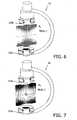
- a “Mode_1”may for example be achieved if the current direction (and thus polarity) of one coil is inverted in each field generator 123a, 123b of Figure 9 (cf. Figure 7 ).
- each mode generating a linear independent configuration of the magnetic fieldis advantageous as it allows an independent measurement of positional coordinates.
- Figure 3once again represents schematically the first embodiment of a magnetic tracking system with three Maxwell coil pairs 21, 22, 23 arranged at different angles with respect to each other.
- Figure 4represents schematically a second embodiment of a magnetic tracking system with one Maxwell coil pair 121a, 121b and two saddle coil pairs 122a, 122b and 123a, 123b, respectively (only one loop is indicated of the corresponding coils).
- Figure 5illustrates the z-component B z of the magnetic field which is generated by the Maxwell coil pair 121a, 121b of Figure 4 (note that similar fields will be generated by Maxwell coils 21, 22, 23 of Figure 3 ).
- Figures 6 and 7illustrate the x-component B x of the magnetic field generated by the saddle coil pair 123a, 123b of Figure 4 in a first "Mode_1" ( Figure 6 ) and a second "Mode_2" ( Figure 7 ).
- Figure 6illustrates the x-component B x of the magnetic field generated by the saddle coil pair 123a, 123b of Figure 4 in a first "Mode_1" ( Figure 6 ) and a second "Mode_2" ( Figure 7 ).
- similar picturescan be generated for the other saddle coil pair 122a, 122b.
Landscapes
- Health & Medical Sciences (AREA)
- Life Sciences & Earth Sciences (AREA)
- Engineering & Computer Science (AREA)
- Surgery (AREA)
- Medical Informatics (AREA)
- Animal Behavior & Ethology (AREA)
- Veterinary Medicine (AREA)
- Public Health (AREA)
- General Health & Medical Sciences (AREA)
- Biomedical Technology (AREA)
- Heart & Thoracic Surgery (AREA)
- Molecular Biology (AREA)
- Pathology (AREA)
- Biophysics (AREA)
- Physics & Mathematics (AREA)
- Nuclear Medicine, Radiotherapy & Molecular Imaging (AREA)
- Human Computer Interaction (AREA)
- Radiology & Medical Imaging (AREA)
- Robotics (AREA)
- Oral & Maxillofacial Surgery (AREA)
- High Energy & Nuclear Physics (AREA)
- Optics & Photonics (AREA)
- Apparatus For Radiation Diagnosis (AREA)
- Magnetic Resonance Imaging Apparatus (AREA)
Description
- The invention relates to a magnetic tracking system comprising means for generating a magnetic field and for measuring it, to an investigation apparatus comprising such a magnetic tracking system, and to a method for determining positional coordinates in the field of view of an imaging system.
- Magnetic tracking systems may inter alia be used in medical applications to determine the position of an object that is not directly visible, for example of a catheter in the body of a patient. Document
US2003/0184285 discloses a magnetic tracking system according to the preamble of claim 1. Another exemplary magnetic tracking system described in theWO 97/36192 - Based on this situation it was an object of the present invention to provide means for the determination of positional coordinates, said means being particularly suited for a combination with (rotational) medical imaging systems.
- This object is achieved by an investigation apparatus according to claim 1, and by a method according to claim 8. Preferred embodiments are disclosed in the dependent claims.
- The investigation apparatus comprises a magnetic tracking system that can be used to determine positional coordinates at a point of interest, wherein "positional coordinates" shall by definition comprise any quantitative information about the position and/or orientation of an object of interest at a certain point in space. Positional coordinates may for example comprise the Cartesian coordinates x, y, z of the position and the polar coordinates ϕ, ψ of the orientation of a catheter tip. The magnetic tracking system comprises the following components:
- a) At least one first magnetic field generator and at least one second magnetic field generator for commonly generating a spatially varying magnetic field in a measuring volume between said field generators. The field generators may particularly be constituted by electrical coils which have the advantage that the direction, magnitude and temporal course of the magnetic field can readily be controlled by the electrical currents applied to the coils.
- b) At least one detector probe for measuring said magnetic field in the measuring volume.
- An advantage of the aforementioned magnetic tracking system is that the spatially varying magnetic field is generated in the region between two cooperating field generators. The spatial course of the magnetic field in this region is therefore more unique and exhibits a stronger gradient making it less prone to disturbances and more reproducible than the magnetic fields generated by usual field generators which are designed as substantially punctual field sources. The requirement to position two field generators at opposite sides of a measuring volume turns out to be no severe restriction in most medical applications because other components (e.g. elements of an imaging system) have to be disposed around the measuring volume anyway. It should be noted that two field generators are considered to be disposed "on opposite sides of a measuring volume" in this context if the lines connecting the centers of said field generators with the center of the measuring volume enclose an angle of about 90° to about 270° (with an angle of 180° corresponding to an exactly opposite arrangement).
- The distance between the first and the second field generator is preferably more than five times, more preferably more than 30 times, and most preferably more than 200 times the axial length of said generators. By definition, the "axial length of the field generators" is measured in the direction of the line connecting the first and the second field generator in their final arrangements. If the field generators do not have identical dimensions, the "axial length of the field generators" shall be defined as the maximum of their individual lengths. In typical applications, the distance between the first and the second field generator will range from about 0.5 m to 3 m.
- There are several different ways to arrange or orient the magnetic field generators. In a preferred embodiment of the invention, they are arranged in such a way that the generated magnetic field has a spatially unique gradient in the measuring volume. By determining said gradient it is then possible to unambiguously derive the desired positional coordinates of a point of interest in the measuring volume.
- In a particular embodiment of the invention, the first and the second field generators are oppositely oriented magnetic dipoles, for example a so-called "Maxwell coil pair". Such an arrangement has the advantage to generate a strong and uniform gradient of the magnetic field in a region between the two field generators similar to the z-gradient in magnetic resonance imaging systems.
- In another embodiment, at least one of the first and the second field generators comprises a pair of magnetic dipoles that are arranged in axial alignment one behind the other with opposite or with the same polarity. Preferably both the first and second field generator are designed in such a way and arranged spaced apart from each other and parallel to each other, for example in an arrangement that is known as "saddle coil pair". By a suitable combination of the field generators it is then possible to generate a unique overall magnetic field.
- Of course first and second field generators of the kinds described above may be combined, for example in a combined arrangement of Maxwell coil pairs and saddle coil pairs.
- The investigation apparatus comprises an imaging system for the generation of images of an object, e.g. a patient, in a field of view. Said investigation apparatus further comprises the magnetic tracking system with
- a) At least one first magnetic field generator and at least one second magnetic field generator for commonly generating a spatially varying magnetic field in a measuring volume between said field generators, wherein the measuring volume at least partially overlaps with the field of view of the imaging system.
- b) At least one detector probe for measuring said magnetic field in the measuring volume.
- The magnetic tracking system may preferably be realized by one of the embodiments of a magnetic tracking system described above. As the field generators of the magnetic tracking system are arranged on different sides of the measuring volume/field of view, the generated magnetic field is less prone to disturbances by (ferro-)magnetic or conductive components (generating eddy currents) of the imaging system.
- In general, the imaging system of the investigation apparatus may be any device that is adapted to generate images of an object, for example a photographic device, an ultrasound device, a magnetic resonance imaging (MRI) device, a scintillator device, a PET scanner etc. The imaging system may in particular be an X-ray device with a radiation source and an X-ray detector that are disposed on opposite sides of the field of view. X-ray devices are widely used during medical interventions which require a parallel application of magnetic tracking systems for determining the position of an instrument like a catheter.
- The imaging system may especially be a rotational X-ray device, wherein the radiation source and the X-ray detector are attached to a common movable member, for example a rotatable C-arm. A movable or rotatable arrangement of X-ray source and detector is commonly used to generate X-ray projections from different directions, thus allowing to select on optimal point of view and/or to generate three-dimensional images.
- The field generators are attached to movable imaging components of the imaging system. In particular, the first field generator may be attached to the radiation source and the second field generator may be attached to the X-ray detector of a rotational X-ray device (note that the roles of the first and second field generator are symmetrical, i.e. that they may be exchanged). If usual magnetic tracking systems are used in combination with rotational X-ray devices, the time-varying and unpredictable disturbances introduced by the movable metal components of said devices pose severe problems. If the field generators are however attached to the main movable components, the magnetic field generated by the field generators moves in synchronicity with the disturbances, thus remaining stationary in a frame of reference fixed to the moving components. Tracking and imaging space remain correctly co-registered for any position of the imaging system.
- The invention further relates to a method for the determination of positional coordinates in the field of view of an imaging system that has movable imaging components, for example for the determination of the position and/or orientation of a catheter tip in the field of view of a rotational X-ray device. The method may particularly be executed with an investigation apparatus of the kind described above. The method comprises the following steps:
- a) Attaching at least one first magnetic field generator and at least one second magnetic field generator to movable imaging components of the imaging system, wherein the at least one first field generator is attached to a movable imaging component on a side of the field of view and the at least one second field generator is attached to a movable imaging component on an opposing side of the field of view.
- b) Generating a spatially varying magnetic field within the field of view by using the at least one first magnetic field generator and the at least one second magnetic field generator.
- c) Measuring the aforementioned magnetic field at a position of interest and calculating the positional coordinates corresponding to said position from said measurement.
- The method comprises in general form the steps that can be executed with an investigation apparatus of the kind described above. Therefore, reference is made to the preceding description for more information on the details, advantages and improvements of that method.
- These and other aspects of the invention will be apparent from and elucidated with reference to the embodiment(s) described hereinafter. These embodiments will be described by way of example with the help of the accompanying drawings in which:
Fig. 1 shows a schematic perspective view of a C-arm X-ray device equipped with a magnetic tracking system according to a first embodiment of the present invention;Fig. 2 depicts the course of the z-component of the magnetic field along the z-direction ofFigure 1 ;Fig. 3 shows schematically the three Maxwell coil pairs used in the first embodiment ofFigure 1 ;Fig. 4 shows schematically one Maxwell coil pair and two saddle coils pairs used in a second embodiment of the invention;Fig. 5 illustrates the z-component of the magnetic field generated by the Maxwell coil pair ofFigure 4 ;Fig. 6 illustrates the x-component of the magnetic field generated by a saddle coil pair ofFigure 4 in a first mode;Fig. 7 illustrates the x-component of the magnetic field generated by a saddle coil pair ofFigure 4 in a second mode;Fig. 8 schematically shows the arrangement of a Maxwell coil pair;Fig. 9 schematically shows the arrangement of a saddle coil pair driven in Mode_1.- Like reference numbers in the Figures refer to identical or similar components.
Figure 1 shows in a perspective view arotational X-ray device 10 which comprises as usual aradiation source 13 and anX-ray detector 11 that are facing each other from opposite sides of a field of view and are fixed to opposite ends of a C-arm 12. The C-arm 12 can be rotated about an axis (not shown) for varying the projection direction accordingly.- In order to determine the position and/or orientation of an object in the field of view, the
rotational X-ray device 10 is equipped with a magnetic tracking system according to the present invention. Said magnetic tracking system comprises, in the shown embodiment, three pairs of field generators in the form of coils, wherein each pair consists of a first field generator orcoil X-ray source 13, and a second field generator orcoil first field generator 21a and thesecond field generator 21b, constitutes a so-called "Maxwell coil pair" if the current is directed through the coils in such a way that they have an opposite magnetic polarity. Figure 8 shows separately the arrangement of theMaxwell coil pair Figure 2 shows the course of the z-component Bz of the corresponding magnetic field B along the z-axis. Said z-axis points along the axis ofcoils X-ray source 13 to the X-ray detector 11 (Figure 1 ) with theX-ray source 13 being arranged at z = -750 mm and theX-ray detector 11 being arranged at z = 750 mm. As can be seen fromFigure 2 , the magnetic field has a unique, uniform, and strong gradient in an intermediate region of about ± 300 mm. This region can then be used as a measuring volume V (Figure 1 ) to determine the positional coordinates of an object of interest.- For the aforementioned measurements, a detector probe or
coil 24 can be used which is brought into the measuring volume V. Such a coil is typically very small and attached to a medical instrument like a catheter. By measuring the magnetic field (or at least one component of it) at the position of thecoil 24, it is possible to calculate the positional coordinates of said coil according to principles known to a person skilled in the art. The coordinates are preferably expressed in a Cartesian coordinate system which is fixed to theimaging system 10, because the magnetic field does change in said system during rotational movements. - Instead of the Maxwell coil pair described above, other arrangements of first and second field generators may be used, too.
Figure 9 shows for example a possible arrangement which is known as "saddle coil pair" and used for instance in the area of magnetic resonance tomography. Thefirst field generator 123a of this arrangement consists of two coils arranged in axial alignment one behind the other with opposite magnetic polarity. Thesecond field generator 123b is identical to the first one but shifted in direction of the shown z-axis (which is perpendicular to the axes of the coils) and opposite in polarities. - The polarities shown in
Figure 9 are achieved if the four coils are driven with current in a "Mode_2" as indicated by the arrows. As each coil can be individually supplied with current, many other modes are possible, too. A "Mode_1" may for example be achieved if the current direction (and thus polarity) of one coil is inverted in eachfield generator Figure 9 (cf.Figure 7 ). In general, each mode generating a linear independent configuration of the magnetic field is advantageous as it allows an independent measurement of positional coordinates. Figure 3 once again represents schematically the first embodiment of a magnetic tracking system with three Maxwell coil pairs 21, 22, 23 arranged at different angles with respect to each other. In contrast to this,Figure 4 represents schematically a second embodiment of a magnetic tracking system with oneMaxwell coil pair saddle coil pairs Figure 5 illustrates the z-component Bz of the magnetic field which is generated by theMaxwell coil pair Figure 4 (note that similar fields will be generated by Maxwell coils 21, 22, 23 ofFigure 3 ).- In a similar way,
Figures 6 and 7 illustrate the x-component Bx of the magnetic field generated by thesaddle coil pair Figure 4 in a first "Mode_1" (Figure 6 ) and a second "Mode_2" (Figure 7 ). Besides a rotation of 90° about the z-axis, similar pictures can be generated for the othersaddle coil pair - Other modifications of the described embodiments may comprise different numbers and/or arrangements of the first and second field generators with respect to the imaging system. Moreover, the roles of the generators and detectors of the magnetic field may be exchanged. It should also be noted that the application of the present invention is not restricted to the described examples or to medical applications.
- Finally it is pointed out that in the present application the term "comprising" does not exclude other elements or steps, that "a" or "an" does not exclude a plurality, and that a single processor or other unit may fulfill the functions of several means. The invention resides in each and every novel characteristic feature and each and every combination of characteristic features. Moreover, reference signs in the claims shall not be construed as limiting their scope.
Claims (9)
- An investigation apparatus comprising an imaging system for the generation of images of an object in a field of view and a magnetic tracking system witha) at least one first magnetic field generator (21a, 22a, 23a, 121a, 122a, 123a) and at least one second magnetic field generator (21b, 22b, 23b, 121b, 122b, 123b) for commonly generating a spatially varying magnetic field (B) in a measuring volume (V) between said magnetic field generators, wherein the measuring volume (V) at least partially overlaps with the field of view;b) at least one detector probe (24) for measuring said magnetic field (B) in the measuring volume (V);
wherein the imaging system comprises movable imaging components (11, 13) on opposite sides of the field of view,characterized in that the at least one first magnetic field generator (21a, 22a, 23a, 121a, 122a, 123a) is attached to a movable imaging component (11) on a side of the field of view and the at least one second magnetic field generator (21b, 22b, 23b, 121b, 122b, 123b) is attached to a movable imaging component (13) on an opposing side of the field of view. - The investigation apparatus according to claim 1,characterized in that the imaging system comprises an X-ray device (10) with a radiation source (13) and an X-ray detector (11) as the movable imaging components.
- The investigation apparatus according to claim 1,characterized in that the distance between the first (21a, 22a, 23a, 121a, 122a, 123a) and the second magnetic field generator (21b, 22b, 23b, 121b, 122b, 123b) corresponds to more than five times, preferably more than 30 times, most preferably more than 200 times the axial length of said field generators.
- The investigation apparatus according to claim 1,characterized in that the magnetic field (B) has a spatially unique gradient in the measuring volume (V).
- The investigation apparatus according to claim 1,characterized in that first (21a) and second magnetic field generators (21b) are oppositely oriented magnetic dipoles.
- The investigation apparatus according to claim 1,characterized in that at least one of the first (122a, 123a) and the second magnetic field generators (122b, 123b) comprises a pair of magnetic dipoles disposed in axial alignment with the same or with an opposite polarity.
- The investigation apparatus according to claim 1,characterized in that the magnetic field generators (21a, 22a, 23a, 121a, 122a, 123a; 21b, 22b, 23b, 121b, 122b, 123b) are constituted by electrical coils.
- A method for the determination of positional coordinates in the field of view of an imaging system (10) with movable imaging components (11, 13), comprisinga) attaching at least one first magnetic field generator (21a, 22a, 23a, 121a, 122a, 123a) and at least one second magnetic field generator (21b, 22b, 23b, 121b, 122b, 123b) to movable imaging components (11, 13) of the imaging system,characterized in that the at least one first field generator (21a, 22a, 23a, 121a, 122a, 123a) is attached to a movable imaging component (11) on a side of the field of view and the at least one second field generator (21b, 22b, 23b, 121b, 122b, 123b) is attached to a movable imaging component (13) on an opposing side of the field of view;b) generating a spatially varying magnetic field (B) within the field of view by using the at least one first magnetic field generator (21a, 22a, 23a, 121 a, 122a, 123a) and the at least one second magnetic field generator (21b, 22b, 23b, 121b, 122b, 123b);c) measuring said magnetic field (B) at a position of interest and inferring positional coordinates corresponding to said position from said measurement.
- The method according to claim 8,characterized in that it is executed with an investigation apparatus according to one of claims 1 to 7.
Priority Applications (1)
| Application Number | Priority Date | Filing Date | Title |
|---|---|---|---|
| EP06795798.5AEP1926426B1 (en) | 2005-09-08 | 2006-08-28 | Magnetic tracking system for an imaging system |
Applications Claiming Priority (3)
| Application Number | Priority Date | Filing Date | Title |
|---|---|---|---|
| EP05108224 | 2005-09-08 | ||
| EP06795798.5AEP1926426B1 (en) | 2005-09-08 | 2006-08-28 | Magnetic tracking system for an imaging system |
| PCT/IB2006/052980WO2007029139A2 (en) | 2005-09-08 | 2006-08-28 | Magnetic tracking system for an imaging system |
Publications (2)
| Publication Number | Publication Date |
|---|---|
| EP1926426A2 EP1926426A2 (en) | 2008-06-04 |
| EP1926426B1true EP1926426B1 (en) | 2014-10-08 |
Family
ID=37836208
Family Applications (1)
| Application Number | Title | Priority Date | Filing Date |
|---|---|---|---|
| EP06795798.5ANot-in-forceEP1926426B1 (en) | 2005-09-08 | 2006-08-28 | Magnetic tracking system for an imaging system |
Country Status (4)
| Country | Link |
|---|---|
| US (1) | US8232798B2 (en) |
| EP (1) | EP1926426B1 (en) |
| JP (1) | JP5666091B2 (en) |
| WO (1) | WO2007029139A2 (en) |
Families Citing this family (19)
| Publication number | Priority date | Publication date | Assignee | Title |
|---|---|---|---|---|
| US20090040029A1 (en)* | 2006-08-10 | 2009-02-12 | V2Green, Inc. | Transceiver and charging component for a power aggregation system |
| US8382372B2 (en) | 2008-07-09 | 2013-02-26 | Siemens Aktiengesellschaft | Medical apparatus |
| EP2408375B1 (en) | 2009-03-20 | 2017-12-06 | Orthoscan Incorporated | Moveable imaging apparatus |
| US8821017B2 (en) | 2010-04-13 | 2014-09-02 | Carestream Health, Inc. | Projector as collimator light |
| US8873712B2 (en) | 2010-04-13 | 2014-10-28 | Carestream Health, Inc. | Exposure control using digital radiography detector |
| US8827554B2 (en) | 2010-04-13 | 2014-09-09 | Carestream Health, Inc. | Tube alignment for mobile radiography system |
| US8867705B2 (en) | 2010-04-13 | 2014-10-21 | Carestream Health, Inc. | Display of AEC sensor location |
| US8710843B2 (en)* | 2010-04-27 | 2014-04-29 | University Health Network | Magnetic resonance imaging apparatus for use with radiotherapy |
| US10165992B2 (en) | 2010-10-18 | 2019-01-01 | Carestream Health, Inc. | X-ray imaging systems and devices |
| WO2012082799A1 (en) | 2010-12-13 | 2012-06-21 | Orthoscan, Inc. | Mobile fluoroscopic imaging system |
| US8821015B2 (en) | 2011-03-08 | 2014-09-02 | Carestream Health, Inc. | Alignment apparatus for X-ray imaging system |
| EP2816956B1 (en) | 2012-02-22 | 2018-01-17 | Carestream Health, Inc. | Mobile radiographic apparatus/methods with tomosynthesis capability |
| WO2013183276A1 (en) | 2012-06-07 | 2013-12-12 | パナソニック株式会社 | Device for measuring rotation angle of catheter tip, method for measuring rotation angle of catheter tip, and program for measuring rotation angle of catheter tip |
| WO2014043412A1 (en)* | 2012-09-12 | 2014-03-20 | Baek Seung H | Method and apparatus for more accurate positioning of dental imaging equipment |
| EP2880459B1 (en)* | 2012-09-21 | 2020-09-09 | Siemens Healthcare GmbH | Hybrid examination system having an mr scanner, an x-ray source and an x-ray detector |
| JP6436894B2 (en)* | 2015-11-17 | 2018-12-12 | 三菱電機株式会社 | Coil apparatus for magnetic particle imaging and magnetic particle imaging apparatus |
| KR101740553B1 (en) | 2016-03-14 | 2017-05-26 | 재단법인대구경북과학기술원 | Magnetic field precise control system with x-ray apparatus |
| KR102848978B1 (en)* | 2022-10-26 | 2025-08-21 | 주식회사 미라큐어 | Magnetic actuation system compatible with C-arm |
| WO2025123036A1 (en)* | 2023-12-08 | 2025-06-12 | See All AI Inc. | Wire-based calibration apparatus for x-ray imaging systems |
Family Cites Families (16)
| Publication number | Priority date | Publication date | Assignee | Title |
|---|---|---|---|---|
| EP0531081A1 (en) | 1991-09-03 | 1993-03-10 | General Electric Company | Tracking system to follow the position and orientation of a device with radiofrequency fields |
| US5558091A (en)* | 1993-10-06 | 1996-09-24 | Biosense, Inc. | Magnetic determination of position and orientation |
| DE59706099D1 (en) | 1996-03-27 | 2002-02-28 | Mednetix Ag Villigen | DEVICE AND METHOD FOR DETERMINING THE POSITION |
| DE19703556A1 (en)* | 1997-01-31 | 1998-08-06 | Philips Patentverwaltung | Method and arrangement for determining the position in X-ray imaging |
| US6477398B1 (en)* | 1997-11-13 | 2002-11-05 | Randell L. Mills | Resonant magnetic susceptibility imaging (ReMSI) |
| WO2000010456A1 (en) | 1998-08-02 | 2000-03-02 | Super Dimension Ltd. | Intrabody navigation system for medical applications |
| US6099459A (en)* | 1998-09-04 | 2000-08-08 | Jacobson; Jerry I. | Magnetic field generating device and method of generating and applying a magnetic field for treatment of specified conditions |
| WO2000037955A2 (en)* | 1998-12-23 | 2000-06-29 | Jakab Peter D | Magnetic resonance scanner with electromagnetic position and orientation tracking device |
| US6233476B1 (en)* | 1999-05-18 | 2001-05-15 | Mediguide Ltd. | Medical positioning system |
| US6856826B2 (en)* | 2000-04-28 | 2005-02-15 | Ge Medical Systems Global Technology Company, Llc | Fluoroscopic tracking and visualization system |
| JP3632073B2 (en)* | 2001-02-07 | 2005-03-23 | 国立がんセンター総長 | Medical magnetic device |
| US6774624B2 (en)* | 2002-03-27 | 2004-08-10 | Ge Medical Systems Global Technology Company, Llc | Magnetic tracking system |
| US6812700B2 (en)* | 2002-08-05 | 2004-11-02 | The Board Of Trustees Of The Leland Stanford Junior University | Correction of local field inhomogeneity in magnetic resonance imaging apparatus |
| US7881769B2 (en)* | 2002-11-18 | 2011-02-01 | Mediguide Ltd. | Method and system for mounting an MPS sensor on a catheter |
| US8126224B2 (en)* | 2004-02-03 | 2012-02-28 | Ge Medical Systems Global Technology Company, Llc | Method and apparatus for instrument tracking on a scrolling series of 2D fluoroscopic images |
| US8131342B2 (en)* | 2004-08-24 | 2012-03-06 | General Electric Company | Method and system for field mapping using integral methodology |
- 2006
- 2006-08-28USUS12/065,648patent/US8232798B2/ennot_activeExpired - Fee Related
- 2006-08-28WOPCT/IB2006/052980patent/WO2007029139A2/enactiveApplication Filing
- 2006-08-28JPJP2008529725Apatent/JP5666091B2/ennot_activeExpired - Fee Related
- 2006-08-28EPEP06795798.5Apatent/EP1926426B1/ennot_activeNot-in-force
Also Published As
| Publication number | Publication date |
|---|---|
| EP1926426A2 (en) | 2008-06-04 |
| US20080204012A1 (en) | 2008-08-28 |
| WO2007029139A2 (en) | 2007-03-15 |
| WO2007029139A3 (en) | 2007-11-01 |
| US8232798B2 (en) | 2012-07-31 |
| JP5666091B2 (en) | 2015-02-12 |
| JP2009507543A (en) | 2009-02-26 |
Similar Documents
| Publication | Publication Date | Title |
|---|---|---|
| EP1926426B1 (en) | Magnetic tracking system for an imaging system | |
| US8358128B2 (en) | Surgical navigation system with magnetoresistance sensors | |
| EP0722290B1 (en) | Magnetic determination of position and orientation | |
| JP5581042B2 (en) | Object tracking system | |
| US6421551B1 (en) | Method for registering images of a subject with a magnetic resonance system and magnetic resonance system for the implementation of the method | |
| KR101618213B1 (en) | Information providing method and apparatus for aligning x-ray tube and detector of mobile x-ray, and wireless detector | |
| US9265442B2 (en) | Method of calibrating combined field location and MRI tracking | |
| US8131342B2 (en) | Method and system for field mapping using integral methodology | |
| US20100249571A1 (en) | Surgical navigation system with wireless magnetoresistance tracking sensors | |
| EP2915483B1 (en) | Calibration jig for a flat location pad | |
| US9632152B2 (en) | Phased array RF coil module and magnetic resonance imaging apparatus using the same | |
| JPH03267054A (en) | Stationary lobotomy aid | |
| JP2019080934A (en) | Position tracking system | |
| WO2007108190A1 (en) | Magnetic resonance imager and rf coil for magnetic resonance imager | |
| AU2019226244A1 (en) | Catheter with synthetic aperture mri sensor | |
| US20190170838A1 (en) | Coil apparatus, magnetic resonance imaging apparatus, and method of controlling the coil apparatus | |
| CN114795175A (en) | Magnetic resonance imaging device | |
| CN114159163A (en) | Soft mirror-oriented magnetic navigation system and method | |
| US20090085559A1 (en) | System and method for minimizing electromagnetic field distortion in an electromagnetic tracking system | |
| Shen et al. | Effects of sensor orientation on AC electromagnetic tracking system accuracy in a CT scanner environment | |
| CN217561704U (en) | Local coil and system comprising a local coil and a grid | |
| Famoriji et al. | A 3-Dimmensional Magnetometer-Aided Low-Field Electromagnetic Tracking System for Clinical Surgery Applications | |
| JP2005137411A (en) | Magnetic resonance imaging equipment | |
| WO2023069326A1 (en) | Magnetic tracking systems and methods of determining position and orientation | |
| WO2007007630A1 (en) | Magnetic resonance imaging apparatus |
Legal Events
| Date | Code | Title | Description |
|---|---|---|---|
| PUAI | Public reference made under article 153(3) epc to a published international application that has entered the european phase | Free format text:ORIGINAL CODE: 0009012 | |
| 17P | Request for examination filed | Effective date:20080502 | |
| RBV | Designated contracting states (corrected) | Designated state(s):AT BE BG CH CY CZ DE DK EE ES FI FR GB GR HU IE IS IT LI LT LU LV MC NL PL PT RO SE SI SK TR | |
| DAX | Request for extension of the european patent (deleted) | ||
| 17Q | First examination report despatched | Effective date:20130417 | |
| RAP1 | Party data changed (applicant data changed or rights of an application transferred) | Owner name:KONINKLIJKE PHILIPS N.V. Owner name:PHILIPS INTELLECTUAL PROPERTY & STANDARDS GMBH | |
| GRAP | Despatch of communication of intention to grant a patent | Free format text:ORIGINAL CODE: EPIDOSNIGR1 | |
| INTG | Intention to grant announced | Effective date:20140411 | |
| GRAS | Grant fee paid | Free format text:ORIGINAL CODE: EPIDOSNIGR3 | |
| GRAA | (expected) grant | Free format text:ORIGINAL CODE: 0009210 | |
| AK | Designated contracting states | Kind code of ref document:B1 Designated state(s):AT BE BG CH CY CZ DE DK EE ES FI FR GB GR HU IE IS IT LI LT LU LV MC NL PL PT RO SE SI SK TR | |
| REG | Reference to a national code | Ref country code:GB Ref legal event code:FG4D | |
| REG | Reference to a national code | Ref country code:CH Ref legal event code:EP Ref country code:AT Ref legal event code:REF Ref document number:690135 Country of ref document:AT Kind code of ref document:T Effective date:20141015 | |
| REG | Reference to a national code | Ref country code:IE Ref legal event code:FG4D | |
| REG | Reference to a national code | Ref country code:DE Ref legal event code:R096 Ref document number:602006043302 Country of ref document:DE Effective date:20141120 | |
| REG | Reference to a national code | Ref country code:NL Ref legal event code:VDEP Effective date:20141008 | |
| REG | Reference to a national code | Ref country code:AT Ref legal event code:MK05 Ref document number:690135 Country of ref document:AT Kind code of ref document:T Effective date:20141008 | |
| REG | Reference to a national code | Ref country code:LT Ref legal event code:MG4D | |
| PG25 | Lapsed in a contracting state [announced via postgrant information from national office to epo] | Ref country code:NL Free format text:LAPSE BECAUSE OF FAILURE TO SUBMIT A TRANSLATION OF THE DESCRIPTION OR TO PAY THE FEE WITHIN THE PRESCRIBED TIME-LIMIT Effective date:20141008 | |
| PG25 | Lapsed in a contracting state [announced via postgrant information from national office to epo] | Ref country code:FI Free format text:LAPSE BECAUSE OF FAILURE TO SUBMIT A TRANSLATION OF THE DESCRIPTION OR TO PAY THE FEE WITHIN THE PRESCRIBED TIME-LIMIT Effective date:20141008 Ref country code:LT Free format text:LAPSE BECAUSE OF FAILURE TO SUBMIT A TRANSLATION OF THE DESCRIPTION OR TO PAY THE FEE WITHIN THE PRESCRIBED TIME-LIMIT Effective date:20141008 Ref country code:IS Free format text:LAPSE BECAUSE OF FAILURE TO SUBMIT A TRANSLATION OF THE DESCRIPTION OR TO PAY THE FEE WITHIN THE PRESCRIBED TIME-LIMIT Effective date:20150208 | |
| PG25 | Lapsed in a contracting state [announced via postgrant information from national office to epo] | Ref country code:PL Free format text:LAPSE BECAUSE OF FAILURE TO SUBMIT A TRANSLATION OF THE DESCRIPTION OR TO PAY THE FEE WITHIN THE PRESCRIBED TIME-LIMIT Effective date:20141008 Ref country code:SE Free format text:LAPSE BECAUSE OF FAILURE TO SUBMIT A TRANSLATION OF THE DESCRIPTION OR TO PAY THE FEE WITHIN THE PRESCRIBED TIME-LIMIT Effective date:20141008 Ref country code:CY Free format text:LAPSE BECAUSE OF FAILURE TO SUBMIT A TRANSLATION OF THE DESCRIPTION OR TO PAY THE FEE WITHIN THE PRESCRIBED TIME-LIMIT Effective date:20141008 Ref country code:GR Free format text:LAPSE BECAUSE OF FAILURE TO SUBMIT A TRANSLATION OF THE DESCRIPTION OR TO PAY THE FEE WITHIN THE PRESCRIBED TIME-LIMIT Effective date:20150109 Ref country code:AT Free format text:LAPSE BECAUSE OF FAILURE TO SUBMIT A TRANSLATION OF THE DESCRIPTION OR TO PAY THE FEE WITHIN THE PRESCRIBED TIME-LIMIT Effective date:20141008 Ref country code:LV Free format text:LAPSE BECAUSE OF FAILURE TO SUBMIT A TRANSLATION OF THE DESCRIPTION OR TO PAY THE FEE WITHIN THE PRESCRIBED TIME-LIMIT Effective date:20141008 | |
| REG | Reference to a national code | Ref country code:DE Ref legal event code:R097 Ref document number:602006043302 Country of ref document:DE | |
| REG | Reference to a national code | Ref country code:DE Ref legal event code:R082 Ref document number:602006043302 Country of ref document:DE Representative=s name:MEISSNER, BOLTE & PARTNER GBR, DE Ref country code:DE Ref legal event code:R081 Ref document number:602006043302 Country of ref document:DE Owner name:PHILIPS GMBH, DE Free format text:FORMER OWNER: PHILIPS INTELLECTUAL PROPERTY & STANDARDS GMBH, 20099 HAMBURG, DE Ref country code:DE Ref legal event code:R082 Ref document number:602006043302 Country of ref document:DE Representative=s name:MEISSNER BOLTE PATENTANWAELTE RECHTSANWAELTE P, DE | |
| PG25 | Lapsed in a contracting state [announced via postgrant information from national office to epo] | Ref country code:DK Free format text:LAPSE BECAUSE OF FAILURE TO SUBMIT A TRANSLATION OF THE DESCRIPTION OR TO PAY THE FEE WITHIN THE PRESCRIBED TIME-LIMIT Effective date:20141008 Ref country code:EE Free format text:LAPSE BECAUSE OF FAILURE TO SUBMIT A TRANSLATION OF THE DESCRIPTION OR TO PAY THE FEE WITHIN THE PRESCRIBED TIME-LIMIT Effective date:20141008 Ref country code:SK Free format text:LAPSE BECAUSE OF FAILURE TO SUBMIT A TRANSLATION OF THE DESCRIPTION OR TO PAY THE FEE WITHIN THE PRESCRIBED TIME-LIMIT Effective date:20141008 Ref country code:CZ Free format text:LAPSE BECAUSE OF FAILURE TO SUBMIT A TRANSLATION OF THE DESCRIPTION OR TO PAY THE FEE WITHIN THE PRESCRIBED TIME-LIMIT Effective date:20141008 Ref country code:RO Free format text:LAPSE BECAUSE OF FAILURE TO SUBMIT A TRANSLATION OF THE DESCRIPTION OR TO PAY THE FEE WITHIN THE PRESCRIBED TIME-LIMIT Effective date:20141008 | |
| PLBE | No opposition filed within time limit | Free format text:ORIGINAL CODE: 0009261 | |
| STAA | Information on the status of an ep patent application or granted ep patent | Free format text:STATUS: NO OPPOSITION FILED WITHIN TIME LIMIT | |
| PG25 | Lapsed in a contracting state [announced via postgrant information from national office to epo] | Ref country code:IT Free format text:LAPSE BECAUSE OF FAILURE TO SUBMIT A TRANSLATION OF THE DESCRIPTION OR TO PAY THE FEE WITHIN THE PRESCRIBED TIME-LIMIT Effective date:20141008 | |
| 26N | No opposition filed | Effective date:20150709 | |
| PG25 | Lapsed in a contracting state [announced via postgrant information from national office to epo] | Ref country code:SI Free format text:LAPSE BECAUSE OF FAILURE TO SUBMIT A TRANSLATION OF THE DESCRIPTION OR TO PAY THE FEE WITHIN THE PRESCRIBED TIME-LIMIT Effective date:20141008 | |
| PG25 | Lapsed in a contracting state [announced via postgrant information from national office to epo] | Ref country code:LU Free format text:LAPSE BECAUSE OF FAILURE TO SUBMIT A TRANSLATION OF THE DESCRIPTION OR TO PAY THE FEE WITHIN THE PRESCRIBED TIME-LIMIT Effective date:20150828 Ref country code:MC Free format text:LAPSE BECAUSE OF FAILURE TO SUBMIT A TRANSLATION OF THE DESCRIPTION OR TO PAY THE FEE WITHIN THE PRESCRIBED TIME-LIMIT Effective date:20141008 | |
| REG | Reference to a national code | Ref country code:CH Ref legal event code:PL | |
| GBPC | Gb: european patent ceased through non-payment of renewal fee | Effective date:20150828 | |
| PG25 | Lapsed in a contracting state [announced via postgrant information from national office to epo] | Ref country code:CH Free format text:LAPSE BECAUSE OF NON-PAYMENT OF DUE FEES Effective date:20150831 Ref country code:LI Free format text:LAPSE BECAUSE OF NON-PAYMENT OF DUE FEES Effective date:20150831 | |
| REG | Reference to a national code | Ref country code:IE Ref legal event code:MM4A | |
| PG25 | Lapsed in a contracting state [announced via postgrant information from national office to epo] | Ref country code:IE Free format text:LAPSE BECAUSE OF NON-PAYMENT OF DUE FEES Effective date:20150828 Ref country code:GB Free format text:LAPSE BECAUSE OF NON-PAYMENT OF DUE FEES Effective date:20150828 | |
| REG | Reference to a national code | Ref country code:FR Ref legal event code:PLFP Year of fee payment:11 | |
| PG25 | Lapsed in a contracting state [announced via postgrant information from national office to epo] | Ref country code:HU Free format text:LAPSE BECAUSE OF FAILURE TO SUBMIT A TRANSLATION OF THE DESCRIPTION OR TO PAY THE FEE WITHIN THE PRESCRIBED TIME-LIMIT; INVALID AB INITIO Effective date:20060828 Ref country code:BG Free format text:LAPSE BECAUSE OF FAILURE TO SUBMIT A TRANSLATION OF THE DESCRIPTION OR TO PAY THE FEE WITHIN THE PRESCRIBED TIME-LIMIT Effective date:20141008 | |
| PG25 | Lapsed in a contracting state [announced via postgrant information from national office to epo] | Ref country code:ES Free format text:LAPSE BECAUSE OF FAILURE TO SUBMIT A TRANSLATION OF THE DESCRIPTION OR TO PAY THE FEE WITHIN THE PRESCRIBED TIME-LIMIT Effective date:20141008 | |
| REG | Reference to a national code | Ref country code:FR Ref legal event code:PLFP Year of fee payment:12 | |
| PG25 | Lapsed in a contracting state [announced via postgrant information from national office to epo] | Ref country code:TR Free format text:LAPSE BECAUSE OF FAILURE TO SUBMIT A TRANSLATION OF THE DESCRIPTION OR TO PAY THE FEE WITHIN THE PRESCRIBED TIME-LIMIT Effective date:20141008 | |
| PG25 | Lapsed in a contracting state [announced via postgrant information from national office to epo] | Ref country code:BE Free format text:LAPSE BECAUSE OF FAILURE TO SUBMIT A TRANSLATION OF THE DESCRIPTION OR TO PAY THE FEE WITHIN THE PRESCRIBED TIME-LIMIT Effective date:20141008 | |
| PG25 | Lapsed in a contracting state [announced via postgrant information from national office to epo] | Ref country code:PT Free format text:LAPSE BECAUSE OF FAILURE TO SUBMIT A TRANSLATION OF THE DESCRIPTION OR TO PAY THE FEE WITHIN THE PRESCRIBED TIME-LIMIT Effective date:20141008 | |
| REG | Reference to a national code | Ref country code:FR Ref legal event code:PLFP Year of fee payment:13 | |
| REG | Reference to a national code | Ref country code:DE Ref legal event code:R082 Ref document number:602006043302 Country of ref document:DE Representative=s name:MEISSNER BOLTE PATENTANWAELTE RECHTSANWAELTE P, DE Ref country code:DE Ref legal event code:R081 Ref document number:602006043302 Country of ref document:DE Owner name:PHILIPS GMBH, DE Free format text:FORMER OWNER: PHILIPS GMBH, 20099 HAMBURG, DE | |
| PGFP | Annual fee paid to national office [announced via postgrant information from national office to epo] | Ref country code:FR Payment date:20230824 Year of fee payment:18 Ref country code:DE Payment date:20230828 Year of fee payment:18 | |
| REG | Reference to a national code | Ref country code:DE Ref legal event code:R119 Ref document number:602006043302 Country of ref document:DE | |
| PG25 | Lapsed in a contracting state [announced via postgrant information from national office to epo] | Ref country code:DE Free format text:LAPSE BECAUSE OF NON-PAYMENT OF DUE FEES Effective date:20250301 | |
| PG25 | Lapsed in a contracting state [announced via postgrant information from national office to epo] | Ref country code:FR Free format text:LAPSE BECAUSE OF NON-PAYMENT OF DUE FEES Effective date:20240831 |