EP1924307B1 - Hand-held controller device for an infusion pump - Google Patents
Hand-held controller device for an infusion pumpDownload PDFInfo
- Publication number
- EP1924307B1 EP1924307B1EP06801213AEP06801213AEP1924307B1EP 1924307 B1EP1924307 B1EP 1924307B1EP 06801213 AEP06801213 AEP 06801213AEP 06801213 AEP06801213 AEP 06801213AEP 1924307 B1EP1924307 B1EP 1924307B1
- Authority
- EP
- European Patent Office
- Prior art keywords
- infusion
- controller device
- user
- display
- controller
- Prior art date
- Legal status (The legal status is an assumption and is not a legal conclusion. Google has not performed a legal analysis and makes no representation as to the accuracy of the status listed.)
- Not-in-force
Links
- 238000001802infusionMethods0.000titleclaimsabstractdescription263
- 238000004891communicationMethods0.000claimsabstractdescription119
- 238000000034methodMethods0.000claimsabstractdescription36
- 239000012530fluidSubstances0.000claimsabstractdescription33
- 239000012491analyteSubstances0.000claimsdescription33
- 230000001413cellular effectEffects0.000claimsdescription22
- 230000006870functionEffects0.000claimsdescription15
- 238000012360testing methodMethods0.000claimsdescription15
- 230000007246mechanismEffects0.000claimsdescription9
- 230000008569processEffects0.000claimsdescription8
- 230000004044responseEffects0.000claimsdescription8
- NOESYZHRGYRDHS-UHFFFAOYSA-NinsulinChemical compoundN1C(=O)C(NC(=O)C(CCC(N)=O)NC(=O)C(CCC(O)=O)NC(=O)C(C(C)C)NC(=O)C(NC(=O)CN)C(C)CC)CSSCC(C(NC(CO)C(=O)NC(CC(C)C)C(=O)NC(CC=2C=CC(O)=CC=2)C(=O)NC(CCC(N)=O)C(=O)NC(CC(C)C)C(=O)NC(CCC(O)=O)C(=O)NC(CC(N)=O)C(=O)NC(CC=2C=CC(O)=CC=2)C(=O)NC(CSSCC(NC(=O)C(C(C)C)NC(=O)C(CC(C)C)NC(=O)C(CC=2C=CC(O)=CC=2)NC(=O)C(CC(C)C)NC(=O)C(C)NC(=O)C(CCC(O)=O)NC(=O)C(C(C)C)NC(=O)C(CC(C)C)NC(=O)C(CC=2NC=NC=2)NC(=O)C(CO)NC(=O)CNC2=O)C(=O)NCC(=O)NC(CCC(O)=O)C(=O)NC(CCCNC(N)=N)C(=O)NCC(=O)NC(CC=3C=CC=CC=3)C(=O)NC(CC=3C=CC=CC=3)C(=O)NC(CC=3C=CC(O)=CC=3)C(=O)NC(C(C)O)C(=O)N3C(CCC3)C(=O)NC(CCCCN)C(=O)NC(C)C(O)=O)C(=O)NC(CC(N)=O)C(O)=O)=O)NC(=O)C(C(C)CC)NC(=O)C(CO)NC(=O)C(C(C)O)NC(=O)C1CSSCC2NC(=O)C(CC(C)C)NC(=O)C(NC(=O)C(CCC(N)=O)NC(=O)C(CC(N)=O)NC(=O)C(NC(=O)C(N)CC=1C=CC=CC=1)C(C)C)CC1=CN=CN1NOESYZHRGYRDHS-UHFFFAOYSA-N0.000abstractdescription30
- 102000004877InsulinHuman genes0.000abstractdescription15
- 108090001061InsulinProteins0.000abstractdescription15
- 229940125396insulinDrugs0.000abstractdescription15
- 238000012544monitoring processMethods0.000abstractdescription15
- 238000005259measurementMethods0.000description27
- 239000008280bloodSubstances0.000description18
- 210000004369bloodAnatomy0.000description18
- 238000002560therapeutic procedureMethods0.000description18
- WQZGKKKJIJFFOK-GASJEMHNSA-NGlucoseNatural productsOC[C@H]1OC(O)[C@H](O)[C@@H](O)[C@@H]1OWQZGKKKJIJFFOK-GASJEMHNSA-N0.000description16
- 239000008103glucoseSubstances0.000description16
- 235000013305foodNutrition0.000description15
- 230000015654memoryEffects0.000description13
- 229940079593drugDrugs0.000description8
- 239000003814drugSubstances0.000description8
- 238000010586diagramMethods0.000description6
- 210000003811fingerAnatomy0.000description6
- 239000000463materialSubstances0.000description6
- 210000001124body fluidAnatomy0.000description5
- 238000013479data entryMethods0.000description5
- 230000009471actionEffects0.000description4
- 238000005516engineering processMethods0.000description4
- 235000012054mealsNutrition0.000description4
- 230000003278mimic effectEffects0.000description4
- 238000001228spectrumMethods0.000description4
- 206010067584Type 1 diabetes mellitusDiseases0.000description3
- 230000008901benefitEffects0.000description3
- 239000010839body fluidSubstances0.000description3
- 238000004364calculation methodMethods0.000description3
- 230000008859changeEffects0.000description3
- 230000001351cycling effectEffects0.000description3
- 238000003745diagnosisMethods0.000description3
- 230000001771impaired effectEffects0.000description3
- 230000003287optical effectEffects0.000description3
- 238000012545processingMethods0.000description3
- 238000012546transferMethods0.000description3
- 238000013519translationMethods0.000description3
- 230000000007visual effectEffects0.000description3
- XEEYBQQBJWHFJM-UHFFFAOYSA-NIronChemical compound[Fe]XEEYBQQBJWHFJM-UHFFFAOYSA-N0.000description2
- WHXSMMKQMYFTQS-UHFFFAOYSA-NLithiumChemical compound[Li]WHXSMMKQMYFTQS-UHFFFAOYSA-N0.000description2
- 238000001467acupunctureMethods0.000description2
- QVGXLLKOCUKJST-UHFFFAOYSA-Natomic oxygenChemical compound[O]QVGXLLKOCUKJST-UHFFFAOYSA-N0.000description2
- 230000015572biosynthetic processEffects0.000description2
- 235000021152breakfastNutrition0.000description2
- 230000000747cardiac effectEffects0.000description2
- HVYWMOMLDIMFJA-DPAQBDIFSA-NcholesterolChemical compoundC1C=C2C[C@@H](O)CC[C@]2(C)[C@@H]2[C@@H]1[C@@H]1CC[C@H]([C@H](C)CCCC(C)C)[C@@]1(C)CC2HVYWMOMLDIMFJA-DPAQBDIFSA-N0.000description2
- 239000003086colorantSubstances0.000description2
- 206010012601diabetes mellitusDiseases0.000description2
- 230000003292diminished effectEffects0.000description2
- 230000002255enzymatic effectEffects0.000description2
- 206010015037epilepsyDiseases0.000description2
- 229940088597hormoneDrugs0.000description2
- 239000005556hormoneSubstances0.000description2
- 229910052744lithiumInorganic materials0.000description2
- 230000007257malfunctionEffects0.000description2
- 238000007726management methodMethods0.000description2
- 229910052760oxygenInorganic materials0.000description2
- 239000001301oxygenSubstances0.000description2
- 230000002093peripheral effectEffects0.000description2
- 238000003786synthesis reactionMethods0.000description2
- 210000003813thumbAnatomy0.000description2
- 102100026189Beta-galactosidaseHuman genes0.000description1
- 208000032953Device battery issueDiseases0.000description1
- 108090000790EnzymesProteins0.000description1
- 102000004190EnzymesHuman genes0.000description1
- 208000032041Hearing impairedDiseases0.000description1
- 108010059881LactaseProteins0.000description1
- JVTAAEKCZFNVCJ-UHFFFAOYSA-MLactateChemical compoundCC(O)C([O-])=OJVTAAEKCZFNVCJ-UHFFFAOYSA-M0.000description1
- 241001465754MetazoaSpecies0.000description1
- 208000007101Muscle CrampDiseases0.000description1
- 206010028347Muscle twitchingDiseases0.000description1
- 206010060860Neurological symptomDiseases0.000description1
- 208000005392SpasmDiseases0.000description1
- 230000004913activationEffects0.000description1
- 230000003044adaptive effectEffects0.000description1
- 238000011374additional therapyMethods0.000description1
- 239000000853adhesiveSubstances0.000description1
- 230000001070adhesive effectEffects0.000description1
- 230000000202analgesic effectEffects0.000description1
- 238000011394anticancer treatmentMethods0.000description1
- 239000000427antigenSubstances0.000description1
- 102000036639antigensHuman genes0.000description1
- 108091007433antigensProteins0.000description1
- 108010005774beta-GalactosidaseProteins0.000description1
- 230000005540biological transmissionEffects0.000description1
- 210000004556brainAnatomy0.000description1
- 150000001720carbohydratesChemical class0.000description1
- 230000015556catabolic processEffects0.000description1
- 210000004027cellAnatomy0.000description1
- 230000009920chelationEffects0.000description1
- 239000003795chemical substances by applicationSubstances0.000description1
- 235000012000cholesterolNutrition0.000description1
- 238000012790confirmationMethods0.000description1
- 238000013144data compressionMethods0.000description1
- 238000006731degradation reactionMethods0.000description1
- 238000013461designMethods0.000description1
- 238000004146energy storageMethods0.000description1
- 229940088598enzymeDrugs0.000description1
- 210000003722extracellular fluidAnatomy0.000description1
- 210000003414extremityAnatomy0.000description1
- 230000002218hypoglycaemic effectEffects0.000description1
- 238000002347injectionMethods0.000description1
- 239000007924injectionSubstances0.000description1
- 238000003780insertionMethods0.000description1
- 230000037431insertionEffects0.000description1
- 229910052742ironInorganic materials0.000description1
- 229940116108lactaseDrugs0.000description1
- 238000003032molecular dockingMethods0.000description1
- 238000012806monitoring deviceMethods0.000description1
- 235000008935nutritiousNutrition0.000description1
- 229940124583pain medicationDrugs0.000description1
- 206010033675panniculitisDiseases0.000description1
- 238000000554physical therapyMethods0.000description1
- 102000004169proteins and genesHuman genes0.000description1
- 108090000623proteins and genesProteins0.000description1
- 208000002815pulmonary hypertensionDiseases0.000description1
- 230000036387respiratory rateEffects0.000description1
- 210000003296salivaAnatomy0.000description1
- 235000011888snacksNutrition0.000description1
- 230000005236sound signalEffects0.000description1
- 210000004304subcutaneous tissueAnatomy0.000description1
- 239000000126substanceSubstances0.000description1
- 210000004243sweatAnatomy0.000description1
- 210000001138tearAnatomy0.000description1
- 208000001072type 2 diabetes mellitusDiseases0.000description1
- 238000002604ultrasonographyMethods0.000description1
- 210000002700urineAnatomy0.000description1
- 230000003612virological effectEffects0.000description1
- 229940088594vitaminDrugs0.000description1
- 239000011782vitaminSubstances0.000description1
- 229930003231vitaminNatural products0.000description1
- 235000013343vitaminNutrition0.000description1
- XLYOFNOQVPJJNP-UHFFFAOYSA-NwaterSubstancesOXLYOFNOQVPJJNP-UHFFFAOYSA-N0.000description1
Images


Classifications
- A—HUMAN NECESSITIES
- A61—MEDICAL OR VETERINARY SCIENCE; HYGIENE
- A61M—DEVICES FOR INTRODUCING MEDIA INTO, OR ONTO, THE BODY; DEVICES FOR TRANSDUCING BODY MEDIA OR FOR TAKING MEDIA FROM THE BODY; DEVICES FOR PRODUCING OR ENDING SLEEP OR STUPOR
- A61M5/00—Devices for bringing media into the body in a subcutaneous, intra-vascular or intramuscular way; Accessories therefor, e.g. filling or cleaning devices, arm-rests
- A61M5/14—Infusion devices, e.g. infusing by gravity; Blood infusion; Accessories therefor
- A61M5/168—Means for controlling media flow to the body or for metering media to the body, e.g. drip meters, counters ; Monitoring media flow to the body
- A61M5/172—Means for controlling media flow to the body or for metering media to the body, e.g. drip meters, counters ; Monitoring media flow to the body electrical or electronic
- A61M5/1723—Means for controlling media flow to the body or for metering media to the body, e.g. drip meters, counters ; Monitoring media flow to the body electrical or electronic using feedback of body parameters, e.g. blood-sugar, pressure
- A—HUMAN NECESSITIES
- A61—MEDICAL OR VETERINARY SCIENCE; HYGIENE
- A61M—DEVICES FOR INTRODUCING MEDIA INTO, OR ONTO, THE BODY; DEVICES FOR TRANSDUCING BODY MEDIA OR FOR TAKING MEDIA FROM THE BODY; DEVICES FOR PRODUCING OR ENDING SLEEP OR STUPOR
- A61M5/00—Devices for bringing media into the body in a subcutaneous, intra-vascular or intramuscular way; Accessories therefor, e.g. filling or cleaning devices, arm-rests
- A61M5/14—Infusion devices, e.g. infusing by gravity; Blood infusion; Accessories therefor
- A61M5/142—Pressure infusion, e.g. using pumps
- A61M5/14244—Pressure infusion, e.g. using pumps adapted to be carried by the patient, e.g. portable on the body
- A—HUMAN NECESSITIES
- A61—MEDICAL OR VETERINARY SCIENCE; HYGIENE
- A61M—DEVICES FOR INTRODUCING MEDIA INTO, OR ONTO, THE BODY; DEVICES FOR TRANSDUCING BODY MEDIA OR FOR TAKING MEDIA FROM THE BODY; DEVICES FOR PRODUCING OR ENDING SLEEP OR STUPOR
- A61M2205/00—General characteristics of the apparatus
- A61M2205/35—Communication
- A61M2205/3546—Range
- A61M2205/3569—Range sublocal, e.g. between console and disposable
- A—HUMAN NECESSITIES
- A61—MEDICAL OR VETERINARY SCIENCE; HYGIENE
- A61M—DEVICES FOR INTRODUCING MEDIA INTO, OR ONTO, THE BODY; DEVICES FOR TRANSDUCING BODY MEDIA OR FOR TAKING MEDIA FROM THE BODY; DEVICES FOR PRODUCING OR ENDING SLEEP OR STUPOR
- A61M2205/00—General characteristics of the apparatus
- A61M2205/35—Communication
- A61M2205/3576—Communication with non implanted data transmission devices, e.g. using external transmitter or receiver
- A61M2205/3592—Communication with non implanted data transmission devices, e.g. using external transmitter or receiver using telemetric means, e.g. radio or optical transmission
- A—HUMAN NECESSITIES
- A61—MEDICAL OR VETERINARY SCIENCE; HYGIENE
- A61M—DEVICES FOR INTRODUCING MEDIA INTO, OR ONTO, THE BODY; DEVICES FOR TRANSDUCING BODY MEDIA OR FOR TAKING MEDIA FROM THE BODY; DEVICES FOR PRODUCING OR ENDING SLEEP OR STUPOR
- A61M2205/00—General characteristics of the apparatus
- A61M2205/58—Means for facilitating use, e.g. by people with impaired vision
- A61M2205/581—Means for facilitating use, e.g. by people with impaired vision by audible feedback
- A—HUMAN NECESSITIES
- A61—MEDICAL OR VETERINARY SCIENCE; HYGIENE
- A61M—DEVICES FOR INTRODUCING MEDIA INTO, OR ONTO, THE BODY; DEVICES FOR TRANSDUCING BODY MEDIA OR FOR TAKING MEDIA FROM THE BODY; DEVICES FOR PRODUCING OR ENDING SLEEP OR STUPOR
- A61M2205/00—General characteristics of the apparatus
- A61M2205/80—General characteristics of the apparatus voice-operated command
- A—HUMAN NECESSITIES
- A61—MEDICAL OR VETERINARY SCIENCE; HYGIENE
- A61M—DEVICES FOR INTRODUCING MEDIA INTO, OR ONTO, THE BODY; DEVICES FOR TRANSDUCING BODY MEDIA OR FOR TAKING MEDIA FROM THE BODY; DEVICES FOR PRODUCING OR ENDING SLEEP OR STUPOR
- A61M2209/00—Ancillary equipment
- A61M2209/01—Remote controllers for specific apparatus
Definitions
- a displayIn infusion systems where a display is included for convenient viewing of selected information, such as that requested by the user or an instructed act that was undertaken by the infusion device, the display is generally located on the infusion device. This may be inconvenient for the user to view information because the infusion device is typically secured to or near an infusion site on the user's body. Thus, viewing may require the user to move or manipulate the infusion device to view the display which may lead to improper reading of the display.
- WO 2004/009161a system is described which includes a blood glucose meter and an infusion device, both with displays. The infusion device can be programmed via a Keypad on the glucose meter. Attention is also drawn to US 2004/073095 , US2003/060765 and WO 00/47109
- the infusion deviceis the central hub with peripheral devices being the controller device and a characteristic determining device.
- the characteristic determining devicebeing adapted to sense and determine the concentration of an analyte of a patient and directs the infusion device fluid delivery according to the measurements. While the term “analyte" is used herein, it is possible to determine and use other characteristics as well using the same type of system.
- the controlis maintained in the central hub and the infusion device sends out most of the commands.
- the infusion devicealso sends requests to receive specific data from the controller device and the characteristic determining device, if one is included.
- the usercan open communication via the internet to obtain communications from, and send communications to, a nurse, parent, or anyone so desired.
- a transceivermay be used to facilitate data transfer between the PC and the infusion device.
- Such a communicationmay also be used by a party, other than the user, to control, suspend, and/or clear alarms.
- This embodimentcould be very useful for a parent to monitor the infusion system of a child, or for a physician to monitor the infusion system of a patient.
- further description of a communication stationmay be found in U.S. Patent. No. 5,376,070 .
- the controller device 110includes a housing 115 adapted to be carried by the user, and a BG meter receptacle 120 coupled to the housing 115 for receiving and testing BG level from the user to determine a concentration of the BG in the user.
- a BG test strip 125 that holds a user's blood sampleis inserted into the BG meter receptacle 120 for the testing by the controller device 110.
- the controller device 110has a display 130 on the housing 115 to show information requested by the user or an instructed act that was undertaken by the infusion device, such as for example, determined concentration of blood glucose levels, graphs of blood glucose level trends or fluid delivery information.
- the infusion device 450may communicate directly with the BG meter 482.
- the resolutionneed not be the same, and the infusion device and/or controller can compensate for the resolution difference so that one or the other may utilize enhanced displays or a simple display depending on the devices and the needs of the user.
- the information regarding the screens displayedis sent to the controller device 410, and when the infusion pump device 450 needs to display a screen, it sends a screen number to the controller device 410.
- screen displaysif the data being sent is fixed, then the screen can be simply displayed. If the data is variable, then the variable data is sent with the screen to the infusion pump device 450. The screen is then displayed based on a combination of the fixed screen information and the variable data. Exchange IDs, strings to be displayed, and foreign languages are among data that may be sent from the controller device 410.
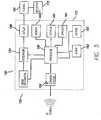
- the custom IC 558is in communication with the sensors 580.
- the electronics architecturefurther may include a communications block 595 in communication with the custom IC 558.
- the communications block 595may be adapted to provide communication via one or more communications methods, such as RF 596, a USB 597, and IR 598.
- the custom IC 558may be replaced by electronic circuitry, discrete or other circuitry, with similar functions.
- the controller deviceis a display only, used to show a BG value and/or graph.
- the controller deviceembodies only a virtual keypad that may mimic exactly the buttons on the infusion device.
- the controller devicetells the infusion device what button was pressed - and the infusion device acts as if the button was pressed on the infusion device itself.
- Each component of the infusion systemmay be of different degrees of sophistication.
- the controller devicecan range from a simple key fob with limited capabilities and with, for example, one or two keys to a complex device with memory, many keys and advanced graphing options.
Landscapes
- Health & Medical Sciences (AREA)
- Heart & Thoracic Surgery (AREA)
- Vascular Medicine (AREA)
- Engineering & Computer Science (AREA)
- Anesthesiology (AREA)
- Biomedical Technology (AREA)
- Hematology (AREA)
- Life Sciences & Earth Sciences (AREA)
- Animal Behavior & Ethology (AREA)
- General Health & Medical Sciences (AREA)
- Public Health (AREA)
- Veterinary Medicine (AREA)
- Diabetes (AREA)
- Infusion, Injection, And Reservoir Apparatuses (AREA)
Abstract
Description
- Embodiments of this invention relate generally to infusion systems and methods for delivering fluids into an individual's body. More particularly, embodiments of this invention relate to apparatuses and methods for providing a convenient way in which to monitor and control the fluids delivered to the individual's body.
- Patients with Type 1 diabetes and some patients with Type 2 diabetes use insulin to control their blood glucose (BG) level. Diabetics must modify their daily lifestyle to keep their body in balance. To do so, diabetics need to keep strict schedules, including ingesting timely nutritious meals, partaking in exercise, monitoring BG levels daily, and adjusting and administering insulin dosages accordingly. Testing of BG levels has been both painful and awkward for the patient. Traditionally, insulin dependent diabetics were required to monitor their BG levels by puncturing a finger tip with a needle. Due to the fact that many patients must conduct such a test multiple times throughout the day to regulate their BG levels, the procedure can be painful and inconvenient.
- Typically, patients may employ various calculations to determine the amount of insulin to inject. For example, bolus estimation software is available for calculating an insulin bolus. Patients may use these software programs on an electronic computing device, such as a computer, the Internet, a personal digital assistant (PDA), or an insulin delivery device. Insulin delivery devices include infusion pumps, injection pens, and implantable delivery systems. The better bolus estimation software takes into account the patient's present BG level. Presently, a patient must measure his/her blood glucose using a BG measurement device, such as a test strip meter, a continuous glucose measurement system, or a hospital hemacue. BG measurement devices use various methods to measure the BG level of a patient, such as a sample of the patient's blood, a sensor in contact with a bodily fluid, an optical sensor, an enzymatic sensor, or a fluorescent sensor. When the BG measurement device has generated a BG measurement, the measurement is displayed on the BG measurement device. Then the patient may visually read the BG measurement and physically enter the BG measurement into an electronic computing device to calculate a bolus estimate. Finally, once the bolus estimate is calculated, the patient must inject the insulin bolus or program an insulin delivery device to deliver the bolus into their body. Unfortunately, this process is also cumbersome and is subject to transcribing errors-for example, the patient may inaccurately enter the BG measurement that is displayed on the BG measurement device into the electronic computing device. Thus, if the BG measurement is not entered correctly, the bolus estimate is not accurate, which may lead to the delivery of an inappropriate insulin dose. In other devices, the measurement is transmitted to the electronic computing device.
- In infusion systems where a display is included for convenient viewing of selected information, such as that requested by the user or an instructed act that was undertaken by the infusion device, the display is generally located on the infusion device. This may be inconvenient for the user to view information because the infusion device is typically secured to or near an infusion site on the user's body. Thus, viewing may require the user to move or manipulate the infusion device to view the display which may lead to improper reading of the display. In
WO 2004/009161 a system is described which includes a blood glucose meter and an infusion device, both with displays. The infusion device can be programmed via a Keypad on the glucose meter. Attention is also drawn toUS 2004/073095 ,US2003/060765 andWO 00/47109 - The invention is as defined in
claims 1 and 15 below. In accordance with embodiments of the invention, an infusion system is provided that allows for the control of the delivery of a fluid or medication. An embodiment of the present invention includes a controller device and a therapy/diagnostic device, such as an infusion device. The controller device may be a hand-held device, separate from the infusion device, that allows the user to communicate with the infusion device without actually handling the infusion device. - The controller device includes a housing adapted to be carried by the user and a communication system contained in the housing for transmitting a communication or command from the user to the infusion device. In alternative embodiments, the controller device may deceive communications sent from the infusion device or other components of the infusion system, such as for example, a characteristic determining device. Further, the controller device may include a user input device on the controller device housing, such as keys, buttons, or the like, for the user to input data or commands.
- The controller device includes on the housing a display that mimics the display on the infusion device. In certain embodiments, whatever is shown on the infusion device corresponds to that shown and reflected on the display of the controller device. The controller device display shows information according to communications sent to it from the infusion device. The user may more conveniently view what is being processed or acted upon in the infusion device without removing or adjusting the infusion device to view the display. In further embodiments, the controller device may be configured so that the input devices included allow all, or substantially all, viewing and data entry to be performed on the controller device without moving or referring to the infusion device.
- Among other advantages, embodiments of the present invention may provide convenience and ease of use. For example, an embodiment with a user interface and display on the controller device may cater to the active lifestyles of many insulin dependent diabetics. A large and simple display minimizes the potential for error in reading and interpreting test data. A small overall size permits discretion during self-monitoring and makes it easy to carry. In another embodiment, the controller device may be integrated with a characteristic determining device into one housing and feature a large target area for strip insertion to make the monitoring procedure fast and accurate. In some embodiments, the controller device display may include a dedicated backlight to facilitate viewing.
- The controller device also reflects the other functions that the particular infusion device may show, including a variety of other displays, for example, when the last bolus was administered, when the last alarm occurred, when the last finger stick was taken, past trends, all alarms that occurred in a time period, calibrations, meals, exercise, bolus schedules, temporary basal delivery, diagnostic information, and the like. Whenever a bolus is being delivered, the infusion device can send a message every time a tenth of a unit, or some specified amount, is delivered, to which the user may monitor via the controller device display.
- In certain embodiments, the infusion device is the central hub with peripheral devices being the controller device and a characteristic determining device. The characteristic determining device being adapted to sense and determine the concentration of an analyte of a patient and directs the infusion device fluid delivery according to the measurements. While the term "analyte" is used herein, it is possible to determine and use other characteristics as well using the same type of system. The control is maintained in the central hub and the infusion device sends out most of the commands. The infusion device also sends requests to receive specific data from the controller device and the characteristic determining device, if one is included.
- In particular embodiments, where the controller device is integrated with the characteristic determining device into one housing, the controller device may automatically transmit communications including the data indicative of the determined concentration of the analyte in the user to the infusion device. In other particular embodiments, the controller device further includes a user input device for inputting commands, and transmits the communications to the infusion device in response to a command from the user input device. In additional embodiments, the controller device further includes an indicator to indicate a status of the communication including the data indicative of the determined concentration of the analyte in the user being transmitted from the determining device communication system to the infusion device communication system. Data compression may be employed to speed up communications.
- In further embodiments, the infusion device may contain all or substantially all of the intelligence. The amount of time that the controller communicates with the infusion device or other components may be limited to save power in the controller device. For example, radiofrequency (RF) communications may be minimized, such that the marriage between the infusion device and controller occurs once until further communication is necessary to exchange data. The information regarding the screens displayed is sent to the controller, and when the infusion device needs to display a screen, it sends a screen number to the controller. In the case of screen displays, if the data being sent is fixed, then the screen can be simply displayed. If the data is variable, then the variable data is sent with the screen to the infusion device. Exchange IDs, strings to be displayed, and foreign languages are among data that may be sent from the controller. Further commands that may be sent from the infusion device include, among other commands, a command to show a specific screen on the controller device, a command for displaying requested information on the screen, a command for showing the rules for the input devices, a command for showing the intelligence about that screen type (e.g., menus, data entries, etc.), and the like.
- The controller device and the infusion device may communicate to one another through wireless or non-wireless methods. Some examples of wireless methods include, by no way in limitation, RF, infrared (IR), Bluetooth, ZigBee, and other 802.15 protocols, 802.11 WiFi, spread spectrum communication, and frequency hopping communication. Further examples include giving the controller device cellular telephone or pager capabilities. In the alternative, the communication may be wired, such as in hospital use. In a wired embodiment, there may be a tether physically connecting the infusion device to the controller device. In yet another alternative, the controlling device and the infusion device could be both wired and wireless-when wired, the two components communicate by wire, and when disconnected, the two components could operate through wireless communication.
- In another wireless example, if the user has access to a computer network or phone connection, the user can open communication via the internet to obtain communications from, and send communications to, a nurse, parent, or anyone so desired. A transceiver may be used to facilitate data transfer between the PC and the infusion device. Such a communication may also be used by a party, other than the user, to control, suspend, and/or clear alarms. This embodiment could be very useful for a parent to monitor the infusion system of a child, or for a physician to monitor the infusion system of a patient. As a non-limiting example, further description of a communication station may be found in
U.S. Patent. No. 5,376,070 . The transceiver may allow patients at home or clinicians in a hospital setting to communicates with the various components of the infusion system via RF telemetry. The transceiver may be used to download device information from the infusion device and sent to the PC when the transceiver is connected in to the serial port of the PC. In embodiments, the transceiver may derive its power from the PC when the two are connected. In this way, the transceiver conveniently does not require a separate power source. In another embodiment, a cellular phone may be used as a conduit for remote monitoring and programming. In yet other embodiments, the controller device may also act as a transceiver, which would eliminate an extra component. - In yet further embodiments, the infusion system includes an infusion device and/or a sensing device. The sensing device includes a sensor and a transmitter in communication with the infusion device. The transmission may occur via wire or wireless methods. The sensing device includes a sensor and a transmitter in communication with the infusion device. The sensing device may sense an analyte of a bodily fluid of the user and provide continuous monitoring of that analyte. The sensing device may be calibrated using data from the infusion device and/or from a characteristic determining device. In further embodiments, the sensing device senses additional physiological characteristics. In still further embodiments, the system is set up to automatically call for assistance when analytes reach a certain level. The system may be set up to notify others, for example, through a cellular network. In such a manner, the patient's cellular telephone may be used to connect to emergency services. The call may include a global positioning system (GPS) location. GPS functions may be included separately from cellular telephone type functions.
- Communications between the system components may be performed in a variety of manners. In an embodiment using RF options, there could be employed a "spread spectrum" where a large range of RFs can be used to relay the communication. In another embodiment, changing frequencies can be used so as to pick up whatever frequency is present. This is known as frequency hopping, where the frequency changes periodically or so to take advantage of all, or substantially all, frequencies available. Another embodiment is one that uses adaptive frequency selection, or Listen Before Talk (LBT), where the devices select the cleanest available channel from those allotted prior to transmitting. In some cases, frequency hopping allows the system to find frequencies that are not being used by other nearby systems and thus avoid interference. In addition, a system may operate in a manner where each component-to-component communication is on a different frequency, or where the delay for each communication is different. Other types of RF, that are not described, may also be used for communication, such as, translation frequency.
- A detailed description of embodiments of the invention will be made with reference to the accompanying drawings, wherein like numerals designate corresponding parts in the figures.
Fig. 1 is a front view of a controller device according to an embodiment of the invention.Fig. 2 is a front view of a blood glucose meter integrated into a controller device housing according to an embodiment of the invention.Fig. 3 is a front view of a blood glucose meter integrated into a controller device housing according to another embodiment of the invention.Fig. 4 is a front view of a blood glucose meter integrated into a controller device housing communicating with an infusion device according to an embodiment of the invention.Fig. 5 is a block diagram of an RF communication system in the infusion device according to an embodiment of the invention.Fig. 6a is a block diagram of a controller device according to an embodiment of the invention.Fig. 6b is a block diagram of a controller device according to an embodiment of the invention.Fig. 7 is a block diagram of different communication paths within the infusion system according to an embodiment of the invention.Fig. 8 is a diagram of the electronics architecture of a controller device according to an embodiment of the invention with a custom integrated circuit.- In the following description, reference is made to the accompanying drawings which form a part hereof and which illustrate several embodiments of the present inventions. It is understood that other embodiments may be utilized and structural and operational changes may be made without departing from the scope of the present inventions.
- In one embodiment, the controller device is a hand-held device separate from the therapy/diagnostic device, such as an infusion device, that allows the user to communicate with the therapy/diagnostic device without actually handling the device. Other examples of therapy/diagnostic devices include electronic therapy devices and devices that receive diagnostic information from cardiac and other sensors. As illustrated in
Fig. 1 , the controller device 5 includes ahousing 3 adapted to be carried by the user and a communication system (not shown) contained in thehousing 3 for transmitting a communication or command from the user to the infusion device. In further embodiments, the controller device 5 may receive communications sent from the infusion device or other components of the infusion system, such as for example, a characteristic determining device. Further, the controller device may include one or moreuser input devices controller device housing 3, such as keys, buttons, or the like, for the user to input data or commands. The controller device 5 includes adisplay 4 on thecontroller device housing 3 which simultaneously displays whatever information and/or graph is being displayed on the infusion device display at that moment. Thedisplay 4 allows a user to easily monitor and control what actions are taking place in, or being performed by, the infusion device. In some embodiments, the controller device 5 may further include a backlight 1 in thecontroller device display 4 for easier viewing. The backlight may be adapted to be in one or more colors, which can be user selectable for personalized use. In further embodiments, the backlight may be adapted to flash and/or turn to a color such as yellow or red when various alerts and alarms take place. In additional embodiments, the controller device 5 may include accessories such ashand straps 6 to provide convenient handling. In particular embodiments, the controller is sized smaller than 6 inches long by 4 inches wide by 1 inch thick. - In certain embodiments, a characteristic determining device that senses and determines the concentration of an analyte of a patient, for example blood glucose ("BG"), and controls the infusion device according to the measurements, may be included in an infusion system with the controller device and the infusion device. The characteristic determining device includes a housing, a receptacle coupled to the housing for receiving and testing an analyte from the user to determine a concentration of the analyte in the user, a processor contained in the housing and coupled to the receptacle for processing the determined concentration of the analyte from the receptacle, and a communication system contained in the housing and coupled to the processor for transmitting a communication including data indicative of the determined concentration of the analyte in the user. In particular embodiments, the characteristic determining device may also include a lancing device coupled to the receptacle for obtaining the analyte from the user.
- In embodiments, the infusion device includes a housing adapted to be carried by the user, a drive mechanism contained in the housing and operatively coupled with a reservoir containing the fluid for infusing the fluid into the body of the user, a communication system contained in the housing for receiving the communication including the data indicative of the determined concentration of an analyte in the user from a characteristic determining device, and a processor contained in the housing and coupled to the communication system for processing the data indicative of the determined concentration of the analyte in the user and controlling the infusion device. In particular embodiments, the infusion device is sized smaller than 152.4 mm (6 inches) long by 101.6mm (4 inches) wide by 25.4 mm (1 inch) thick.
- The infusion device may further include a bolus estimator used in conjunction with the processor for calculating an estimated amount of fluid to be infused into the body of the user based upon the received data indicative of the determined concentration of the analyte in the user and a target concentration of the analyte in the user, and an indicator to indicate when the estimated amount of fluid to be infused has been calculated. The system may determine the concentration of one of any variety of analyte types including, but not limited to, oxygen, blood, temperature, lactase, pH, implantable, and the like. Additionally, the infusion device may include a user input device, such as keys, buttons, or the like, for inputting an estimate of a material to be ingested by the user, and the bolus estimator may include the capability to calculate the estimated amount of fluid to be infused into the body of the user based upon the inputted estimate of the material to be ingested by the user. The infusion device may also include a memory for storing the data indicative of the determined concentration of the analyte in the user received by the infusion device communication system from the determining device communication system.
- In still further alternative embodiments, the characteristic determining device is a BG measurement device and may use samples from body fluids other than blood, such as interstitial fluid, spinal fluid, saliva, urine, tears, sweat, or the like. In yet other alternative embodiments, other measurement devices may be utilized to determine the concentrations, levels, or quantities of other characteristics, analytes, or agents in the user, such as hormones, cholesterol, oxygen, pH, lactate, heart rate, respiratory rate, medication concentrations, viral loads (e.g., HIV), or the like. In still other alternative embodiments, other fluids may be delivered to the user, such as medication other than insulin (e.g., HIV drugs, drugs to treat pulmonary hypertension, iron chelation drugs, pain medications, and anti-cancer treatments), chemicals, enzymes, antigens, hormones, vitamins, or the like. Particular embodiments are directed towards the use in humans; however, in alternative embodiments, the infusion devices may be used in animals. For pain management, a bolus function may be set up as a Patient Controlled Analgesic (PCA) function for customized delivery or the user may press a preset bolus button several times.
- In other embodiments, the characteristic determining device is a BG meter that determines BG level and the infusion device is an insulin infusion pump. The BG meter communicates the measurement of BG to the infusion pump device to determine the amount of insulin for delivery to the user. In alternative embodiments, the BG measurement device may be a continuous glucose measurement system, a hospital hemacue, an automated intermittent blood glucose measurement system, and the like, and/or the BG measurement device may use other methods for measuring the user's BG level, such as a sensor in contact with a body fluid, an optical sensor, a RF sensor, an enzymatic sensor, a fluorescent sensor, a blood sample placed in a receptacle, or the like. The BG measurement device may generally be of the type and/or include features disclosed in
WO 2000/19887 WO2000/18210 US 6558320 , and entitled "Handheld Personal Data Assistant (PDA) with a Medical Device and Method of Using the Same," andUS 2002/0002326 (alsoUS 6641533 ) and entitled "Handheld Personal Data Assistant (PDA) with a Medical Device and Method of Using the Same." Such BG measurement devices may be adapted to be carried by the user, for example, in the hand, on the body, in a clothing pocket, attached to clothing (e.g., using a clip, strap, adhesive, or fastener), and the like. In particular embodiments, the BG measurement device is sized smaller than 15.24 cm (6 inches) long by 10.16 cm (4 inches) wide by 2.54 cm (1 inch) thick. - In alternative embodiments of the invention, the BG meter may be integrated into the controller device housing, as shown in
Fig. 2 , where thecontroller device housing 15 includes aBG meter receptacle 20. Thecontroller 10 includes ahousing 15 adapted to be carried by the user, aBG meter receptacle 20 coupled to thehousing 15 for receiving and testing BG level from the user to determine a concentration of the BG in the user. ABG test strip 25 that holds a use blood sample is inserted into theBG meter receptacle 20 for the testing by thecontroller device 10. In variations, thecontroller device 10 may have a cartridge-like mechanism which loads and presents the strip for testing and then ejects it. Thecontroller device 10 has adisplay 30 on thehousing 15 to show information requested by the user or an instructed act that was undertaken by the infusion device, such as for example, determined concentration of blood glucose levels, BG trends or graphs, such as described and disclosed in U.S. Patent ApplicationUS 2004/167464 , entitled "System for Monitoring Physiological Characteristics." Thedisplay 30 may further include adedicated backlight 35 to facilitate viewing. Thebacklight 35 may be a user programmable multi-color backlight that additionally performs the function of a visual indicator by flashing colors appropriate to the level of an alert or alarm. Thebacklight 35 may also have variable intensity (automatic or manual) to preserve the battery power and improved viewing. Thecontroller 10 includes akeypad 40 on which various input devices, such as keys, buttons, or the like, are located. Thekeypad buttons - The power of the controller device and of the other various devices discussed herein may be provided from a battery. The battery may be a single use or a rechargeable battery. Where the battery is rechargeable, there may be a connector or other interface on a device to attach the device to an electrical outlet, docking station, portable recharger, or so forth to recharge the battery while in the device. It is also possible that a rechargeable battery may be removable from the device for recharging outside of the device, however, in some cases, the rechargeable battery may be sealed into the housing of the device to create a more water resistant or waterproof housing. The devices may be adapted to accommodate various battery types and shapes. In further embodiments, the devices may be adapted to accommodate more than one type of battery. For example, a device may be adapted to accommodate a rechargeable battery and, in the event of battery failure or other need, also adapted to accommodate a readily available battery, such as a AA battery, AAA battery, or coin cell battery.
- In
Fig. 3 , another embodiment of a controller device is shown. Again, thecontroller device 110 includes ahousing 115 adapted to be carried by the user, and aBG meter receptacle 120 coupled to thehousing 115 for receiving and testing BG level from the user to determine a concentration of the BG in the user. ABG test strip 125 that holds a user's blood sample is inserted into theBG meter receptacle 120 for the testing by thecontroller device 110. Thecontroller device 110 has adisplay 130 on thehousing 115 to show information requested by the user or an instructed act that was undertaken by the infusion device, such as for example, determined concentration of blood glucose levels, graphs of blood glucose level trends or fluid delivery information. Thedisplay 130 may include adedicated backlight 135 to facilitate viewing. Thecontroller device 110 includes a few input devices, such as keys, buttons, or the like, on thehousing 115. Thehousing buttons Fig. 4 illustrates an embodiment of an infusion system that includes aninfusion device 50, and further includes a controller device integrated with aBG meter 10, where both share one housing. Thecontroller device 10 communicates to theinfusion pump device 50 through a wireless method, for example RF signals. Thecontroller device 10 senses and determines the concentration of BG level of a patient and controls theinfusion device 50 according to the measurements. This substantially reduces, if not eliminates, calculations on the part of the patient. In particular embodiments, theinfusion device 50 includes ahousing 55 adapted to be carried by the user. On thehousing 55 there is included adisplay 60 that, like theBG meter display 30, shows information requested by the user or an instructed act that was undertaken by theinfusion device 50. Theinfusion device 50 may not include a display, but in that case there should be a suspend/resume input and an action input for safety reasons. TheBG meter display 30 shows information according to communications sent to thecontroller device 10 from theinfusion device 50. At any moment, thedisplay 60 of theinfusion device 50 may show substantially the same information as shown on thecontroller device display 30. The two displays may mimic one another so that the user may choose to conveniently view the selected information from thecontroller device 10 rather than theinfusion device 50, which is usually attached to the user's body through the infusion set 75. Theinfusion device 50 delivers fluid from within thehousing 55, throughtubing 80 and into the infusion set 75 into the user's body at an infusion site. Further included on theinfusion device 50 is akeypad 65 with various input devices, such as thekeypad buttons Fig. 5 provides a block diagram of theinfusion device 150. Theinfusion device 150 includes adrive mechanism 152 contained in thehousing 172 and operatively coupled with areservoir 154 containing the fluid for infusing the fluid into the body of the user, acommunication system 156 contained in thehousing 172 for receiving the communication from the controller device including data indicative of the determined concentration of the BG in the user from the BG meter, and aprocessor 158 contained in thehousing 172 and coupled to thecommunication system 156 for processing the received communications and controlling theinfusion device 150. The fluid is delivered from thereservoir 154 through anoutlet 168 in thehousing 172 and into the user's body via thetubing 180 and infusion set 175. Theinfusion device 150 may further include an indicator displayed on thedisplay 160 to indicate when the estimated amount of fluid to be infused has been calculated. Additionally, theinfusion device 150 may include one or more user input device(s), such as keys, buttons, and the like, for inputting an estimate of a material to be ingested by the user, and the estimated amount of fluid to be infused into the body of the user may be based upon this inputted estimate of material to be ingested. A bolus estimator may be used in conjunction with the infusion device processor for estimating the appropriate amount of fluid to be infused into the body of the user. There may be included akeypad 165 on which the one or more input device(s) are located. Theinfusion device 150 may also include a memory 166 for storing the data received by the infusiondevice communication system 156 from the controller device communication system.- In further embodiments, a
speaker 164 is included to provide an alternative mode of communication. In an embodiment, theinfusion device 150 may display a message that states "move nearer to pump" when the BG meter or controller device senses that the communication with theinfusion device 150 is weak or interrupted. A similar message may be displayed if the BG meter or controller device senses some type of problem or malfunction. Alternatively, analarm 162 may alert the user of any problem or malfunction by vibrating, emitting warning sounds, flashing light, and the like. In further embodiments, theinfusion device 150 may provide other functions that show a variety of other displays, for example, when the last bolus was administered, when the last alarm occurred, when the last finger stick was taken, past trends, all alarms that occurred in a time period, calibrations, meals, exercise, bolus schedules, temporary basal delivery, and the like. Whenever a bolus is being delivered, theinfusion device 150 can send a message every time a tenth of a unit, or some specified amount, is delivered. - As seen in
Fig. 6a , thecontroller device 210, includes ahousing 215 adapted to be carried by the user. Aprocessor 212 contained in thehousing 215 is adapted to process data and commands inputted by the user, and a transmitter 218 (or a transceiver 318 (as shown inFig. 6b )) contained in thehousing 215 and coupled to theprocessor 212 transmits such communications, including data indicative of the determined concentration of the BG in the user, to theinfusion device 250. In further embodiments, thecontroller device 210 may be integrated with a BG meter in one housing, which has a lancing device and receptacle for BG test strips, for obtaining a BG sample from the user. - The
controller device 210 may communicate with a remote station, such as acomputer 224, through a data transfer system, using a type ofcommunication connector 222, that couples thecontroller device 210 to thecomputer 224 and allows the data downloading. Alternatively, communication may be by wireless methods, such as RF, IR, Bluetooth or other wireless methods. Data may be downloaded via the RF telemetry in the same manner as data is transferred from thecontroller device 210 to theinfusion pump device 250. The transmitter 218 (or a transceiver 318 (as shown inFig. 6b )) converts RF signals into compatible electrical pulses that may be subsequently sent through a serial port to a specified destination. Data, including software upgrades and diagnostic tools, may also be downloaded via RF telemetry, or any other wireless or wired method, from a remote station, such as thecomputer 224, to theinfusion device 250. Other remote stations include, but are not limited to, a hospital database, a cellular telephone, a PDA, a smart phone or internet. For example, a cellular phone may be used as a conduit for remote monitoring and programming. In one embodiment, the controller device may be configured so as to have cellular telephone capabilities. In further embodiments, the controller device and/or the other devices with display may be capable of providing PDA functions as well, removing the need for patients to carry separate PDA devices. - The
controller device 210 includes on the housing adisplay 230 that may mimic the display on theinfusion pump device 250. Thecontroller device display 230 shows information according to communications sent to thecontroller device 210 from theinfusion device 250. At any moment, the display of theinfusion device 250 may show substantially the same information as shown on thecontroller device display 230. In some embodiments, whatever is shown on theinfusion device 250 corresponds to that shown and reflected on thedisplay 230 of thecontroller device 210. In this manner, the user may more conveniently view what is being processed or acted upon in theinfusion pump device 250 without removing or adjusting theinfusion pump device 250 to view the display. In embodiments, thecontroller device 210 may include one or more input device(s) 245, such as keys, buttons, and the like, on akeypad 265 so that all, or substantially all, viewing and data entry may be performed on the same device without moving theinfusion pump device 250. - The
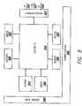
infusion pump device 250 and thecontroller device 210 need to have substantially the same resolution or else the screen may not be presented correctly on the display. Another difficulty may be in properly displaying the scaling of graphs. This issue may be addressed by having the infusion pump device talk in an "ideal" screen, and not necessarily in its actual screen format. As shown inFig. 7 , the potential communication paths within embodiments of the infusion system are illustrated. Thecontroller device 410 may serve as a translator between theinfusion device 450 and the other components of theinfusion system 400, such as aBG meter 482. For example, thecontroller device 410 may have the ability to determine how best to translate the infusion device's 450 description to the screen of the two displays. As can be seen, theinfusion device 450 may communicate directly with theBG meter 482. In alternative embodiments, the resolution need not be the same, and the infusion device and/or controller can compensate for the resolution difference so that one or the other may utilize enhanced displays or a simple display depending on the devices and the needs of the user. - In some embodiments, the
infusion system 400 may include multiple controllers that can communicate with oneinfusion device 450. In other embodiments, there is onecontroller 410 communicating to oneinfusion device 450. The controller may also be integrated into the infusion device in some embodiments. In yet another embodiment, theBG meter 482 may be integrated into thecontroller 410, sharing one housing, to both communicate with theinfusion pump device 450. In this embodiment, the controller is separate from the infusion pump device. In this embodiment, theinfusion device 450 serves as the central hub with most of the intelligence of thesystem 400. In yet another embodiment, thecontroller device 410 may be a key fob, in which case, thecontroller device 410 would serve simply as a virtual keyboard to input data and commands to theinfusion device 450. Optional peripheral devices may include a physiological characteristic sensor device, such as a telemetered glucose monitoring system (TGMS) sensor. Alternatively, the sensor may be directly wired to a monitor/user interface. The TGMS sensor or physiologicalcharacteristic sensor 486 may provide for continuous BG monitoring. The physiologicalcharacteristic sensor 486 may also be linked to abedside monitor 492 so that monitoring and programming of medication delivery may be performed remotely. In some embodiments, the infusion pump device does not include, nor need, a display. In this embodiment, a key fob may serve as a remote display. Other options for a remote display include, but are not limited to, cellular telephones, computer monitors, PDA's, smart phones, watch remotes, and the like. Theinfusion device 450 may further communicate with, and download data such as software upgrades and diagnostic tools from, a remote station like acomputer 424 from aconnector 422. Optionally, theinfusion device 450 may also communicate with thecontroller device 410 through a station such as acellular station 488 that includes GPS. In further embodiments, theconnector 422 may have memory capability to transport data. - In the above embodiment, the control is maintained in the central hub and the
infusion pump device 450 sends out most of the commands. Theinfusion device 450 also sends requests to receive specific data from thecontroller device 410. Thecontroller device 410 and theinfusion pump device 450 may communicate to one another by aconnector 422, other wired methods or by wireless methods, such as RF, IR, Bluetooth, or other wireless methods. In other embodiments, theinfusion pump device 450 may contain all or substantially all of the intelligence. Thecontroller device 410 may be limited in the amount of time that they communicate with one another to save power in thecontroller device 410. For example, RF communications may be minimized, such that the marriage between theinfusion pump device 450 andcontroller device 410 occurs once. The information regarding the screens displayed is sent to thecontroller device 410, and when theinfusion pump device 450 needs to display a screen, it sends a screen number to thecontroller device 410. In the case of screen displays, if the data being sent is fixed, then the screen can be simply displayed. If the data is variable, then the variable data is sent with the screen to theinfusion pump device 450. The screen is then displayed based on a combination of the fixed screen information and the variable data. Exchange IDs, strings to be displayed, and foreign languages are among data that may be sent from thecontroller device 410. Further commands that may be sent from theinfusion pump device 450 include, among other commands, a command to show a specific screen on thecontroller device 410, a command for displaying requested information on the screen, a command for showing the rules for the input devices, a command for showing the intelligence about that screen type (e.g., menus, data entries, etc.), and the like. The devices may all send diagnostic information to each other, and particularly to the controller device, so that the user may see if anything is going wrong with any of the devices. Fig. 8 shows an electronics architecture according to an embodiment of the invention with a custom integrated circuit ("custom IC") 558 as the processor. This architecture can support many of the devices discussed herein, for example the controller device, the infusion device, the characteristic determining device, a BG meter, or any combination of the above. Thecustom IC 558 is in communication with amemory 566,keypad 565, audio devices 564 (such as speakers or audio electronic circuitry such as voice recognition, synthesis or other audio reproduction), and adisplay 560. Where there is a drive mechanism in a device that includes infusion functions, thecustom IC 558 is in communication with amotor 552 or motor drive circuitry or other means of delivering fluids or therapy via an electro-mechanical means. Where there are one more sensors included in the device, or in communication with the device (such as a characteristic determining device or a device which includes a characteristic determining function), thecustom IC 558 is in communication with thesensors 580. The electronics architecture further may include acommunications block 595 in communication with thecustom IC 558. The communications block 595 may be adapted to provide communication via one or more communications methods, such asRF 596, aUSB 597, andIR 598. In further embodiments, thecustom IC 558 may be replaced by electronic circuitry, discrete or other circuitry, with similar functions.- The electronics architecture may include a
main battery 590 and apower control 592. Thepower control 592 may be adapted to give an end of battery warning to the user, which can be predicted based on the type of battery used or can be calculated from the power degradation of the battery being used. However, in certain embodiments it is not necessary to know the type of battery used to create an end of battery warning. Various battery types, such as rechargeable, lithium, alkaline, etc., can be accommodated by this design. In certain embodiments, the electronics architecture includes a removable battery and an internal backup battery. Whenever a new removable battery is inserted, the internal backup battery will be charged to full capacity and then disconnected. After the removable battery has been drained of most of its energy, it will be switched out of the circuit and the internal backup battery will be used to supply power to the device. A low battery warning may then be issued. The internal backup battery may be rechargeable. In further embodiments, a supercap, for example, is used to handle the peak loads that the rechargeable internal battery could not handle directly, because it has sufficient energy storage. This method also allows the use of any type of removable battery (alkaline, lithium, rechargeable, etc.) and partially drained batteries. Depending on use, the backup battery may allow the device to operate for at least one day after the removable battery has been drained or removed. In further embodiments, a microprocessor measures the charge states and control switches for removable and internal backup batteries. - In certain embodiments, the controller device has no user settings and very little memory, because all, or substantially all, needed data and instructions will be sent to the controller device by the infusion pump device. Thus, the functions are all, or substantially all, contained on the infusion pump device in such embodiments.
- In alternative embodiments, the infusion pump device may include expanded capabilities, such as color on the display screens, and more graph options that can present more detailed graphs. For example, there may be included a graph called "mobile day" where the BG levels of the user for the past five days may be shown as overlapping graphs. The mobile day graph allows the user to see the trend in BG level changes during those days, and aids the user in better controlling the insulin delivery according to the trends that appear for specific times of each day.
- The BG meter may also include expanded capabilities, such as for example, voice synthesis, voice activation, polyphonic speakers for the vision impaired, and plugs on the BG meter for headphones. Likewise, the controller devices may also be configured to provide these expanded capabilities.
- As described above, the controller device may be integrated with the BG meter in some embodiments. In those embodiments, the input keys and the display will all, or substantially all, be included on the controller device. The BG meter may also be separate from the controller device and may talk directly to a sensing device, such as a TGMS sensor. The TGMS sensor is inserted into the subcutaneous tissue of the user to read body fluids, and allows for continuous blood glucose monitoring. The readings are used in conjunction with the BG level determined by the BG meter to continuously monitor BG levels through extrapolating the BG measurements. This embodiment would be compatible with users that do not have an infusion pump device, in which case, there is a need for the ability to talk directly to the TGMS sensor without talking to the infusion pump device.
- If the BG meter talks to the TGMS sensor then the TGMS sensor may broadcast the data received from the BG meter to the infusion pump device and the controller device. In some embodiments, the infusion pump device will always send the data to the controller device. In the case that the controller device does not receive the information from the infusion pump device, it will assume that the infusion pump device has not received the data and will communicate the value to infusion pump device. In other embodiments, the infusion pump device, controller device and TGMS sensor maintain a three-way communication with one another, and have the ability to check the contacts between one another. In still further embodiments, the system is set up to automatically call for assistance when analytes reach a certain level. The call may include a GPS location.
- In an embodiment of the present invention, the graph displayed on the controller device may display information regarding boluses, finger sticks, exercise, meals and the like. In one embodiment, the graph displayed has eight segments, representing different limits and an actual BG line. In other embodiments, the graphs may include additional time spans for which to show the varying BG levels. For example, the embodiments may include a 3 hour, 6, 12, and 24 hour graphs. Additional features of the graphs may include the ability to zoom in or out of the graph. There may be included an ESC key that will allow the user to return to the last scale. Other options may allow the user to focus on specific positions on a graph. In yet another feature, the user can select the resolution in which to view the graph.
- In a situation where the infusion pump device and the controller device are out of sync,e.g., the graph on the pump and the graph on the controller device do not look substantially the same, there needs to be a way to resynchronize the two components if something goes wrong. For example, if finger stick values do not both have current finger stick values, then the graphs for the controller device and the infusion pump device would be different.
- There also may be some type of positive mechanism for the controller device if the communication between the controller device and the pump are interrupted. For example, the mechanism may have the controller device stop displaying its graph in a "time-out" phase tor the time the infusion pump device screen is absent or no more data is entered by the user for a period of time. In this case, the infusion pump device operates on the last data that the infusion pump device sent to the controller device to display. In an embodiment, the controller device will display an idle screen during the time-out phase and while the communication between the infusion pump device and the controller device is re-established. The idle screen may remain until the next action is selected by the user. After the time-out phase, the user may press a key to start up the communication again. Once a key is pressed, the controller device will process the key data and the screen will be displayed. The controller device may periodically send signals to the pump to see if it is still active on the screen.
- In alternative embodiments, there will be a positive confirmation requested prior to displaying graphs. For example, the graphs may be shown in bitmap packets (e.g., bit-by-bit), and if the user will be getting a large number of packets of data, for example 15 packets of data, to show the graph, the user may opt not to confirm. The data is passed from the controller device, which is programmed to display the data, to the infusion pump device. The controller device can operate in graphics description language where data is recognized by the controller device as instructing it on which position to put each line or color and the graphics display would handle determining the resolution that the graph would be displayed in. In some embodiments, the graph may be displayed in three-dimensional format.
- The specific screens to be displayed may include fixed menus, partially variable menus, and variable menus. In fixed menus, the menus do not change depending on data. Therefore, they will always look substantially the same on the screen, and the controller device may be programmed to display them when requested. The fixed menus may be described as screen numbers. In this way, the controller device can easily request "screen 1" or "screen 2." In fixed menus, the text is defined once. There may also be menus where menu items appear and disappear depending on the current settings of the infusion pump device. These menus are considered partially variable menus because some data appear and disappear, and are not all fixed. For example, a program for bolus setup allows a user to change current bolus settings. Bolus set up menus involve variable information as well as fixed information. The values may be variable, but the main menu items (title of variables, etc.) will stay the same. Variable menus contain information that is completely variable,e.g., bolus history screen. Variable data is sent at the time of the screen display, and there is generally no fixed text. What is displayed in variable menus depend on what bolus action the user selects. The history screens resemble the menu screens in that the user cannot select and input any information with the history screen. Data entry screens, on the other hand, include multiple fields on a screen and can accept data selection and input by the user.
- Different units may need to be switched dynamically in depending on how the type of entry is communicated. The screens may also need to be able to display minimum and maximum values as well as time increments, to ensure precision of the display. The rules for this translation will be defined in the infusion pump device. Likewise, for a dual-wave bolus, there must be defined how the values interlock. Sensor high and low BG values also need to be interlocked (in some embodiments, these two values will be displayed in the same screen).
- In one embodiment, communication between the infusion system components takes place when the user presses one or more keys to send data to the infusion pump device and, in response, the infusion pump device can relay to the controller device to instruct on what to display. Alternatively, the user may input data through scrolling down menus and selecting options. When the user prompts, the controller device, for example by pressing an "ACT" button, the controller device will then tell the infusion pump what to do,e.g., deliver fluid to the user.
- In its most simplest form, the controller device is a display only, used to show a BG value and/or graph. In another simple form, the controller device embodies only a virtual keypad that may mimic exactly the buttons on the infusion device. When the user presses a key on the controller device, the controller device tells the infusion device what button was pressed - and the infusion device acts as if the button was pressed on the infusion device itself. Each component of the infusion system may be of different degrees of sophistication. For example, the controller device can range from a simple key fob with limited capabilities and with, for example, one or two keys to a complex device with memory, many keys and advanced graphing options. In a complex form, the controller device may embody all or substantially all of the intelligence that is present in the infusion device. In this form, the controller device could do all calculations, graphing functions, and other data input, output, and manipulation at the controller device. The controller device would then send data to the infusion device indicating what the controller device had done so that the infusion device could be put into the same state as the controller. It is possible for the controller device to have many different degrees of computing intelligence, so that few, none, many, or all computing may be done at the controller device. How much intelligence will be in the controller device may depend on battery life, size requirements, and so forth.
- In further embodiments, the processor of the controller device has unique identification information, and the communication transmitted from the controller device to the infusion device further includes the unique identification information of the controller device processor such that the infusion device is capable of discerning whether the communication is intended for receipt by the infusion device. In yet further embodiments, the processor of the infusion device has unique identification information, and the communication transmitted from the controller device to the infusion device further includes the unique identification information of the infusion device processor such that the infusion device is capable of discerning whether the communication is intended for receipt by the infusion device.
- Additionally, both the controller device and the BG meter may communicate over wireless networks. Some examples include RF, IR, Bluetooth, spread spectrum communication, and frequency hopping communication. In further embodiments, there may be a "Listen Before Talk" scheme where the system selects the cleanest of allotted channels through which to communicate. Further examples include giving the controller device cellular telephone or pager capabilities. In the alternative, the communication may be wired, such as in hospital use. In a wired embodiment, there may be a tether physically connecting the infusion pump device to the controller device and/or BG meter. In yet another alternative, the controller device and the infusion pump device could be both wired and wireless-when wired, the two components communicate by wire, and when disconnected, the two components could operate through wireless communication.
- In another wireless example, if the user has access to a computer network or phone connection, the user can open communication via the internet to obtain communications from, and send communications to, a nurse, parent, or anyone so desired. As discussed above, a transceiver may be used to facilitate data transfer between the PC and the infusion pump device. Such a communication may also be used by a party, other than the user, to control, suspend, and/or clear alarms. This embodiment could be very useful for a parent to monitor the infusion system of a child, or for a physician to monitor the infusion system of a patient. The transceiver may allow patients at home or clinicians in a hospital setting to communicates with the various components of the infusion system via RF telemetry. The transceiver may be used to download device information from the pump and sent to the PC when the transceiver is connected in to the serial port of the PC. In embodiments, the transceiver may derive its power from the PC when the two are connected. In this way, the transceiver conveniently does not require a separate power source. In another embodiment, a cellular phone may be used as a conduit for remote monitoring and programming. In yet other embodiments, the controller device with a BG meter may also act as a transceiver, which would eliminate an extra component.
- In further embodiments, the controller device communication system is capable of being deactivated and reactivated. The controller device may include input devices, such as keys, buttons, and the like, for inputting commands, and the communication system of the controller device is capable of being deactivated in response to a first command from the user input device and being reactivated in response to a second command from the user input device. Alternatively, the communication system of the controller device may be automatically reactivated after a predetermined amount of time has elapsed or at a predetermined time of day.
- In an embodiment of the present invention, the processor of the infusion device uses power cycling such that power is periodically supplied to the communication system of the infusion device until a communication is received from the controller device. When a communication is received from the controller device, the processor of the infusion device discontinues using power cycling so that the power is continuously supplied to the infusion device communication system. The infusion device processor may then resume using power cycling upon completing the receipt of the communication including the data indicative of the determined concentration of the analyte in the user from a BG meter communication system.
- In yet another embodiment, the infusion system may include a bedside monitor. The monitor could communicate through the same avenues as the BG meter, the controller device, and the infusion pump device. The monitor could be used, as described above, to remotely alarm people other than the user, such as for example, parents, physicians, nurses, and the like. This would provide an extra layer of monitoring for the user, especially when the user is alone. In further embodiments, the system may be set up so that multiple devices are placed around the house. This would provide easy access to monitor the diabetic. Additionally, the parent will be able to obtain data to monitor a child user at home and when the parent is away. Such home monitors could be set to any mode preferred, for example, flashing lights, warning sounds like beeping, vibration, and the like. Other features may include a function that allows the remote user (parent, physician, nurse, etc.) to change and/or deliver a bolus from remote sites.
- In an alternative, the controller device may be configured so as to have cellular telephone capabilities. The cellular network could provide a conduit for remote monitoring and programming. Additionally, the cellular network could be used to notify parents, physicians, or emergency services of alarms or alert states. A button may be included on the controller device and/or the infusion device to automatically alert a parent, physician, or emergency services when pressed. For example, a monitoring device may be built directly into a patient's cellular telephone so that in the case of a hypoglycemic event, an alarm or connection may be made to emergency services via the cellular telephone. In a further embodiment, GPS technology may also be built into the cellular telephone to allow easy location of the patient. Alternatively, GPS technology may be included in the controller device without cellular telephone technology. In other embodiments, the GPS technology may also be built into the infusion pump, BG meter or controller device.
- The infusion system may be part of a closed-loop system, such as an implantable infusion system with a sensor system or an external infusion device with a sensor system. In such a system, there may be included safety nets, such as alarms and automatic shut-offs.
- The alarms may be customized to specific user needs. The alarm may be set to flashing lights for the hearing impaired, or warning sounds and/or vibration for the vision impaired. There could further be included headphones that can plug into the controller device for vision impaired to instruct the user on what to do in the case that an alarm goes off. The headphones could also be plugged into a MPEG player or the like. To avoid having the pump broadcast information, the alarms may be handled in a way where the user presses a button on the controller device. Alarms could also be included on the pump. There may further be included a turn-off option where, if there is a need to communicate with the controller, the user can choose a selection to turn off the controller. In further embodiments, there may be included a feature in any of the devices including an alarm where when the device has sounded an alarm for a period of time and the user has not responded, the alarm will switch to a vibrate mode and/or will attempt to signal companion devices in the system to alarm the user.
- It is noted that some users can be expected to have somewhat diminished visual and tactile abilities due to the complications from diabetes or other conditions. Thus, the display and buttons or other input devices may be configured and adapted to the needs of a user with diminished visual and tactile abilities. In alternative embodiments, the high level module (and/or the low level module) may communicate to the user by audio signals, such as beeps, speech or the like.
- Other display settings may be customizable, including, but not limited to, the background, sounds, fonts, and wallpaper. There may be a children's mode, with limited features available so that a child cannot dispense too much medication at once. Different display features may be included in the module and/or may be downloaded from a computer. The high level module may have a memory with which to store customized settings or pump control. The memory may be of any type that is known in the art, such as a volatile or non-volatile memory. Both a volatile and non-volatile memory may be used, which can speed up operation of the pump. As an example, non-volatile memories that could be used in the invention include flash memories, thumb drives and/or memory sticks such as USB thumb drives, removable hard drives, and optical drives.
- In some embodiments, the language that the controller device operates in may comprise several different languages, ranging from 1 language to about 40 languages and potentially more. To set language, data must be first initialized to modify the phrases and detail font that may be significantly different in one language as compared to another language. For example, some languages, such as Chinese, are read in vertical columns, from the right to the left, and thus, needs to be displayed in such manner. One way to overcome this complication in using different languages is to have fonts built into the infusion pump device. Because fonts are now described in pen strokes (true-type fonts), rather than in pixels (bit-by-bit) this allows the infusion pump device to determine out how to display the different fonts. Another option could involve uploading the fonts in strings from various sources, such as the internet.
- If so desired, a food library may be downloaded from a PC, or from the internet via a PC. In the food library, each food item will have some information associated with it, for example, carbohydrate count, fat count, proteins, serving size, and the like. The food library may be built directly into the infusion pump device, or it may be downloaded from remote sources, as discussed above. For one example, the food library may be downloaded through a transceiver embodied by the user's cellular telephone. Other options may include eliminating the need to bypass the transceiver every time a food item is selected, such as, downloading the food items from the PC and storing it until use. The food library may also be input directly into the controller device rather than the infusion pump device. If the food library is contained in the infusion pump device, an associated food library menu could be dynamic. The user could select from different layers of the food library the items consumer or about to be consumed and the infusion pump device could calculate the appropriate amount of insulin to be delivered. Variable data could be included for a small food library with less than 50 food items. For example, there could be variable data for a food library dedicated to breakfast foods only. There could be a "breakfast" key or icon on the controller device that the user can select. There may also be "lunch" and "dinner" and "snack" icons.
- Communications between the system components may be performed in a variety of manners. In an embodiment using RF options, there could be employed a single frequency or a "spread spectrum" where a large range of RFs can be used to relay the communication. In another embodiment, changing frequencies can be used so as to pick up whatever frequency is present. This is known as "frequency hopping," where the frequency changes every millisecond or so to take advantage of all, or substantially all, frequencies available. In some cases, frequency hopping allows the system to find frequencies that are not being used by other nearby systems and thus avoid interference. In addition, a system may operate in a manner where each component-to-component communication is on a different frequency, or where the delay for each communication is different. Other types of RF, that are not described, may also be used for communication, such as, translation frequency.
- According to yet another embodiment of the present invention, an infusion system includes a controller device, with a controller device display, and an infusion device, with an infusion device display, and a method for infusing a fluid into a body of a user is provided. The method includes the steps of: receiving data communication from a user, transmitting with the controller device the communication including data to an infusion device, receiving with the infusion device the communication, and displaying with the controller device display information regarding the fluid delivery, where the display on the controller device display shows information according to instructions or communications sent to the controller device from the infusion device. At any moment, the display of the infusion device may correspond with what is displayed on the infusion device display. The method may further include the step of displaying a trends and graphs. Additionally, the method may include the step of inputting an estimate of a material to be ingested by the user, and the estimated amount of fluid to be infused into the body of the user is calculated further based upon the inputted estimate of the material to be ingested by the user.
- Although the above description has been focused on use of a controller device with an infusion device, it is appreciated that a controller device as described herein could be used with any number of therapy/diagnostic devices. For example, in any case where a therapy/diagnostic device is tethered to the body, at least partially implanted in the body, or otherwise inconvenient for the user to manipulate while therapy or diagnosis is being performed, a controller device may be used that can send commands to the therapy/diagnosis device and/or mimic the display on the therapy/diagnosis device. Therapies other than infusion of fluids could include electrical therapy, such as electrical therapy for the brain and for conditions such as epilepsy. Diagnostics could include any number of diagnostics, such as information from cardiac and other sensors.
- Electrical therapy devices include neurostimulation devices for epilepsy, similar devices for pain management, etc. In addition, there are electro-acupuncture devices, where a needle is inserted into the body much like acupuncture, but additional therapy is delivered by electrical impulses. In certain embodiments, the structure of an electrical therapy device may include a needle that is inserted into appropriate areas of the body. The architecture would be similar to that of the devices described above. The patient/user would use the controller device to deliver "dosages" of electrical impulses to alleviate pain and manage neurological symptoms on demand such as twitching, uncontrolled movement of limbs, spasms, and so forth.
- In further embodiments, devices such as those used in physical therapy clinics could be adapted for individual use. For example, a patch or other device placed on the body could be activated by the controller device to delivery said therapy, be it ultrasound, heat or some other media. The architecture for these devices could be similar to the architecture of the devices already described, where a physiological characteristic sensor or infusion device is replaced by a therapy delivering device/mechanism.
Claims (16)
- An infusion system for infusing a fluid into a body of a user, the infusion system comprising:a controller device (5, 10, 110, 210, 310, 410) adapted to be carried by a user, including:a controller device display (4, 30, 130, 230, 330),a controller device transmitter (218, 318) adapted to transmit a first communication, anda controller device receiver (318) adapted to receive a second communication, the second communication including information for display as a first screen on the controller device display (4, 30, 130, 230); andan infusion device (50, 150, 250, 350, 450) adapted to be carried by a user, including:a drive mechanism (152) operatively coupled to a reservoir (154) containing a fluid, the reservoir (154) for infusing the fluid into a body of the user,an infusion device receiver (595) adapted to receive the first communication from the controller device transmitter (218, 318),an infusion device transmitter (595) adapted to transmit the second communication to the controller device receiver (318),an infusion device processor (558) adapted to process the first communication received from the controller device transmitter, andan infusion device display (60, 160), adapted to display a second screen,wherein the controller device display is configured to display the first screen according to the information received from the infusion device, said first screen simultaneously displaying whatever information is being displayed on the second screen, the controller display thereby mimicking the display on the infusion device.
- The infusion system of claim 1, wherein the first communication includes instructions for acts to be performed by the infusion device (50, 150, 250, 350, 450) and the infusion device acts in response to the instructions.
- The infusion system of claim 1, wherein the controller device (5, 10, 110, 210, 410) further includes:a receptacle adapted to receive and test a first analyte from the user to determine a concentration of the first analyte in the user; anda controller device processor coupled to the receptacle, and adapted to process the determined concentration of the first analyte from the receptacle.
- The infusion system of claim 3, wherein the controller device display (4, 30, 130, 230, 330) shows trends of the determined concentration of the first analyte.
- The infusion system of claim 3, wherein the controller device further includes a controller device housing and wherein the controller device display, the controller device transmitter, the controller device receiver, the receptacle, and the controller device processor are each on or in the controller device housing.
- The infusion system of claim 1, further including a characteristic determining device (482) adapted to be carried by the user, having:a receptacle (20, 120) adapted to receive and test a first analyte from the user to determine a concentration of the first analyte in the user;a determining device processor coupled to the receptacle, and adapted to process the determined concentration of the first analyte from the receptacle; anda determining device transmitter coupled to the determining device processor and adapted to transmit a communication including the determined concentration of the first analyte in the user.
- The infusion system of claim 6, wherein the infusion device is adapted to automatically contact an emergency response system if the determined concentration of the first analyte is below or above predetermined levels.
- The infusion system of claim 7, wherein the infusion device is adapted to transmit a global positioning signal to the emergency response system.
- The infusion system of claim 1, wherein the controller device display is adapted to display on a remote device, the remote device selected from the group consisting of a cellular telephone, a computer monitor, a key fob remote, a personal digital assistant, a smart phone, and a watch remote.
- The infusion system of claim 1, wherein the infusion device receiver is further adapted to receive data downloaded from a remote station.
- The infusion system of claim 10, wherein the remote station is selected from the group consisting of a computer, a hospital database, a cellular telephone, a personal digital assistant, a smart phone and internet.
- The infusion system of claim 1, further including a sensing device, the sensing device having:a sensor adapted to determine a concentration of a second analyte in the user;a sensing device processor coupled to the sensor and adapted to process the determined concentration of the second analyte in the user; anda sensing device transmitter coupled to the sensing device processor and adapted to transmit the determined concentration of the second analyte in the user to the controller device receiver.
- The infusion system of claim 12, wherein the sensing device is adapted to continuously determine the concentration of the second analyte in the user.
- The infusion system of claim 1, wherein the infusion device further includes a bolus estimator used in conjunction with the infusion device processor (158) for estimating an amount of fluid to be infused into the body of the user, and wherein the controller device display shows (4, 30, 130, 230, 330) the estimated amount of the fluid to be infused.
- A method of controlling functions of an infusion pump device comprising:transmitting to an infusion pump device (50, 150, 250, 350, 450) from a controller device (5, 10,110, 210, 310, 410) a first communication, wherein the controller device adapted to be carried by a user, includes:a controller device display (4, 30, 130, 230, 330);a controller device transmitter (218, 318) adapted to transmit the first communication, anda controller device receiver (318) adapted to receive a second communication, the second communication including information for display as a first screen on the controller device display (4, 30, 130, 230, 330); andthe infusion device (50, 150, 250, 350, 450) adapted to be carried by the user, includes:a drive mechanism (152) operatively coupled to a reservoir (154) containing a fluid, the reservoir (154) for infusing the fluid into a body of the user,an infusion device receiver (595) adapted to receive the first communication from the controller device transmitter (218, 318),an infusion device transmitter (595) adapted to transmit the second communication to the controller device receiver (318),an infusion device processor (558) adapted to process the first communication received from the controller device transmitter (218, 318), andan infusion device display (60, 160);receiving the second communication from the infusion device (50, 150, 250, 350, 450) at the controller device (4, 30, 130, 230, 330); anddisplaying a first screen on the controller device display (4, 30, 130, 230, 330) according to the information included in the second communication;wherein the method further comprises simultaneously displaying on the first screen whatever information is being displayed on the second screen, the controller device display (4, 30, 130, 230, 330) thereby mimicking the display (60, 160) on the infusion device.
- The method of claim 15, wherein the first communication includes instructions for acts to be performed by the infusion device and the infusion device acts in response to the instructions.
Applications Claiming Priority (2)
| Application Number | Priority Date | Filing Date | Title |
|---|---|---|---|
| US11/204,583US20070060869A1 (en) | 2005-08-16 | 2005-08-16 | Controller device for an infusion pump |
| PCT/US2006/031307WO2007021892A1 (en) | 2005-08-16 | 2006-08-11 | Hand-held controller device for an infusion pump |
Publications (2)
| Publication Number | Publication Date |
|---|---|
| EP1924307A1 EP1924307A1 (en) | 2008-05-28 |
| EP1924307B1true EP1924307B1 (en) | 2012-04-11 |
Family
ID=37433685
Family Applications (1)
| Application Number | Title | Priority Date | Filing Date |
|---|---|---|---|
| EP06801213ANot-in-forceEP1924307B1 (en) | 2005-08-16 | 2006-08-11 | Hand-held controller device for an infusion pump |
Country Status (7)
| Country | Link |
|---|---|
| US (1) | US20070060869A1 (en) |
| EP (1) | EP1924307B1 (en) |
| JP (1) | JP2009504322A (en) |
| AT (1) | ATE552871T1 (en) |
| CA (1) | CA2618698A1 (en) |
| DK (1) | DK1924307T3 (en) |
| WO (1) | WO2007021892A1 (en) |
Cited By (2)
| Publication number | Priority date | Publication date | Assignee | Title |
|---|---|---|---|---|
| US9727696B2 (en) | 2010-08-12 | 2017-08-08 | Fenwel, Inc | Processing blood donation data for presentation on operator interface |
| US11676715B2 (en) | 2010-08-12 | 2023-06-13 | Fenwal, Inc. | System and method for collecting whole blood from blood donors |
Families Citing this family (222)
| Publication number | Priority date | Publication date | Assignee | Title |
|---|---|---|---|---|
| DE10163774A1 (en)* | 2001-12-22 | 2003-07-03 | Roche Diagnostics Gmbh | Plug-in data transfer module, useful in monitoring medical conditions, comprises an interface at the analysis system, and a communication unit to transmit converted electromagnetic/acoustic signals to a data processing station |
| US20080172026A1 (en) | 2006-10-17 | 2008-07-17 | Blomquist Michael L | Insulin pump having a suspension bolus |
| US7811231B2 (en) | 2002-12-31 | 2010-10-12 | Abbott Diabetes Care Inc. | Continuous glucose monitoring system and methods of use |
| US8066639B2 (en) | 2003-06-10 | 2011-11-29 | Abbott Diabetes Care Inc. | Glucose measuring device for use in personal area network |
| US7920906B2 (en) | 2005-03-10 | 2011-04-05 | Dexcom, Inc. | System and methods for processing analyte sensor data for sensor calibration |
| US9247900B2 (en) | 2004-07-13 | 2016-02-02 | Dexcom, Inc. | Analyte sensor |
| WO2005089103A2 (en) | 2004-02-17 | 2005-09-29 | Therasense, Inc. | Method and system for providing data communication in continuous glucose monitoring and management system |
| DE102004020160A1 (en)* | 2004-04-24 | 2005-11-10 | Roche Diagnostics Gmbh | Method and device for monitoring a concentration of an analyte in the living body of a human or animal |
| US7654956B2 (en) | 2004-07-13 | 2010-02-02 | Dexcom, Inc. | Transcutaneous analyte sensor |
| US20070045902A1 (en) | 2004-07-13 | 2007-03-01 | Brauker James H | Analyte sensor |
| US7291107B2 (en)* | 2004-08-26 | 2007-11-06 | Roche Diagnostics Operations, Inc. | Insulin bolus recommendation system |
| US7869851B2 (en)* | 2004-12-23 | 2011-01-11 | Roche Diagnostics Operations, Inc. | System and method for determining insulin bolus quantities |
| US7697967B2 (en) | 2005-12-28 | 2010-04-13 | Abbott Diabetes Care Inc. | Method and apparatus for providing analyte sensor insertion |
| US9788771B2 (en) | 2006-10-23 | 2017-10-17 | Abbott Diabetes Care Inc. | Variable speed sensor insertion devices and methods of use |
| US9636450B2 (en)* | 2007-02-19 | 2017-05-02 | Udo Hoss | Pump system modular components for delivering medication and analyte sensing at seperate insertion sites |
| US7545272B2 (en) | 2005-02-08 | 2009-06-09 | Therasense, Inc. | RF tag on test strips, test strip vials and boxes |
| US20060276771A1 (en)* | 2005-06-06 | 2006-12-07 | Galley Paul J | System and method providing for user intervention in a diabetes control arrangement |
| US8095123B2 (en)* | 2005-06-13 | 2012-01-10 | Roche Diagnostics International Ag | Wireless communication system |
| US8880138B2 (en)* | 2005-09-30 | 2014-11-04 | Abbott Diabetes Care Inc. | Device for channeling fluid and methods of use |
| US7766829B2 (en) | 2005-11-04 | 2010-08-03 | Abbott Diabetes Care Inc. | Method and system for providing basal profile modification in analyte monitoring and management systems |
| WO2007056592A2 (en)* | 2005-11-08 | 2007-05-18 | M2 Medical A/S | Method and system for manual and autonomous control of an infusion pump |
| EP1793228A1 (en)* | 2005-12-05 | 2007-06-06 | F. Hoffmann-La Roche AG | Method to give acoustically an information in an analytical system |
| US7941200B2 (en)* | 2005-12-08 | 2011-05-10 | Roche Diagnostics Operations, Inc. | System and method for determining drug administration information |
| EP1795116A1 (en)* | 2005-12-12 | 2007-06-13 | F. Hoffmann-La Roche AG | System with portable patient device and external operating unit |
| US11298058B2 (en) | 2005-12-28 | 2022-04-12 | Abbott Diabetes Care Inc. | Method and apparatus for providing analyte sensor insertion |
| US7736310B2 (en) | 2006-01-30 | 2010-06-15 | Abbott Diabetes Care Inc. | On-body medical device securement |
| EP3165247B1 (en)* | 2006-02-09 | 2020-10-28 | DEKA Products Limited Partnership | Pumping fluid delivery systems and methods using force application assembley |
| US7885698B2 (en) | 2006-02-28 | 2011-02-08 | Abbott Diabetes Care Inc. | Method and system for providing continuous calibration of implantable analyte sensors |
| US7981034B2 (en) | 2006-02-28 | 2011-07-19 | Abbott Diabetes Care Inc. | Smart messages and alerts for an infusion delivery and management system |
| US7826879B2 (en) | 2006-02-28 | 2010-11-02 | Abbott Diabetes Care Inc. | Analyte sensors and methods of use |
| ES2297779T3 (en)* | 2006-03-30 | 2008-05-01 | F. Hoffmann-La Roche Ag | INFUSION SYSTEM WITH AN INFUSION UNIT AND A DISTANCE CONTROL UNIT. |
| US9392969B2 (en) | 2008-08-31 | 2016-07-19 | Abbott Diabetes Care Inc. | Closed loop control and signal attenuation detection |
| US8374668B1 (en) | 2007-10-23 | 2013-02-12 | Abbott Diabetes Care Inc. | Analyte sensor with lag compensation |
| US8473022B2 (en) | 2008-01-31 | 2013-06-25 | Abbott Diabetes Care Inc. | Analyte sensor with time lag compensation |
| US7653425B2 (en) | 2006-08-09 | 2010-01-26 | Abbott Diabetes Care Inc. | Method and system for providing calibration of an analyte sensor in an analyte monitoring system |
| US7620438B2 (en) | 2006-03-31 | 2009-11-17 | Abbott Diabetes Care Inc. | Method and system for powering an electronic device |
| US8140312B2 (en) | 2007-05-14 | 2012-03-20 | Abbott Diabetes Care Inc. | Method and system for determining analyte levels |
| US8226891B2 (en) | 2006-03-31 | 2012-07-24 | Abbott Diabetes Care Inc. | Analyte monitoring devices and methods therefor |
| US7618369B2 (en) | 2006-10-02 | 2009-11-17 | Abbott Diabetes Care Inc. | Method and system for dynamically updating calibration parameters for an analyte sensor |
| US8346335B2 (en) | 2008-03-28 | 2013-01-01 | Abbott Diabetes Care Inc. | Analyte sensor calibration management |
| US8478557B2 (en) | 2009-07-31 | 2013-07-02 | Abbott Diabetes Care Inc. | Method and apparatus for providing analyte monitoring system calibration accuracy |
| US20080177149A1 (en)* | 2006-06-16 | 2008-07-24 | Stefan Weinert | System and method for collecting patient information from which diabetes therapy may be determined |
| US20080004601A1 (en)* | 2006-06-28 | 2008-01-03 | Abbott Diabetes Care, Inc. | Analyte Monitoring and Therapy Management System and Methods Therefor |
| US9119582B2 (en) | 2006-06-30 | 2015-09-01 | Abbott Diabetes Care, Inc. | Integrated analyte sensor and infusion device and methods therefor |
| US8932216B2 (en) | 2006-08-07 | 2015-01-13 | Abbott Diabetes Care Inc. | Method and system for providing data management in integrated analyte monitoring and infusion system |
| US8206296B2 (en) | 2006-08-07 | 2012-06-26 | Abbott Diabetes Care Inc. | Method and system for providing integrated analyte monitoring and infusion system therapy management |
| US8352042B2 (en)* | 2006-11-28 | 2013-01-08 | The Alfred E. Mann Foundation For Scientific Research | Remote controls and ambulatory medical systems including the same |
| US8352041B2 (en) | 2006-11-28 | 2013-01-08 | The Alfred E. Mann Foundation For Scientific Research | Remote controls and ambulatory medical systems including the same |
| US20080199894A1 (en) | 2007-02-15 | 2008-08-21 | Abbott Diabetes Care, Inc. | Device and method for automatic data acquisition and/or detection |
| US8732188B2 (en) | 2007-02-18 | 2014-05-20 | Abbott Diabetes Care Inc. | Method and system for providing contextual based medication dosage determination |
| US8930203B2 (en)* | 2007-02-18 | 2015-01-06 | Abbott Diabetes Care Inc. | Multi-function analyte test device and methods therefor |
| US8123686B2 (en) | 2007-03-01 | 2012-02-28 | Abbott Diabetes Care Inc. | Method and apparatus for providing rolling data in communication systems |
| US20080221930A1 (en) | 2007-03-09 | 2008-09-11 | Spacelabs Medical, Inc. | Health data collection tool |
| WO2008130897A2 (en) | 2007-04-14 | 2008-10-30 | Abbott Diabetes Care, Inc. | Method and apparatus for providing data processing and control in medical communication system |
| WO2008130895A2 (en) | 2007-04-14 | 2008-10-30 | Abbott Diabetes Care, Inc. | Method and apparatus for providing dynamic multi-stage signal amplification in a medical device |
| CA2683953C (en) | 2007-04-14 | 2016-08-02 | Abbott Diabetes Care Inc. | Method and apparatus for providing data processing and control in medical communication system |
| WO2008130898A1 (en) | 2007-04-14 | 2008-10-30 | Abbott Diabetes Care, Inc. | Method and apparatus for providing data processing and control in medical communication system |
| US10111608B2 (en) | 2007-04-14 | 2018-10-30 | Abbott Diabetes Care Inc. | Method and apparatus for providing data processing and control in medical communication system |
| US20080275326A1 (en)* | 2007-05-01 | 2008-11-06 | Joachim Kasielke | Sensor for monitoring a condition of a patient |
| US8461985B2 (en) | 2007-05-08 | 2013-06-11 | Abbott Diabetes Care Inc. | Analyte monitoring system and methods |
| US8456301B2 (en) | 2007-05-08 | 2013-06-04 | Abbott Diabetes Care Inc. | Analyte monitoring system and methods |
| US8665091B2 (en) | 2007-05-08 | 2014-03-04 | Abbott Diabetes Care Inc. | Method and device for determining elapsed sensor life |
| US7928850B2 (en) | 2007-05-08 | 2011-04-19 | Abbott Diabetes Care Inc. | Analyte monitoring system and methods |
| US20080278332A1 (en)* | 2007-05-08 | 2008-11-13 | Abbott Diabetes Care, Inc. | Analyte monitoring system and methods |
| US20080281179A1 (en)* | 2007-05-08 | 2008-11-13 | Abbott Diabetes Care, Inc. | Analyte monitoring system and methods |
| US8560038B2 (en) | 2007-05-14 | 2013-10-15 | Abbott Diabetes Care Inc. | Method and apparatus for providing data processing and control in a medical communication system |
| US8103471B2 (en) | 2007-05-14 | 2012-01-24 | Abbott Diabetes Care Inc. | Method and apparatus for providing data processing and control in a medical communication system |
| US8600681B2 (en) | 2007-05-14 | 2013-12-03 | Abbott Diabetes Care Inc. | Method and apparatus for providing data processing and control in a medical communication system |
| US10002233B2 (en) | 2007-05-14 | 2018-06-19 | Abbott Diabetes Care Inc. | Method and apparatus for providing data processing and control in a medical communication system |
| US8444560B2 (en) | 2007-05-14 | 2013-05-21 | Abbott Diabetes Care Inc. | Method and apparatus for providing data processing and control in a medical communication system |
| US9125548B2 (en) | 2007-05-14 | 2015-09-08 | Abbott Diabetes Care Inc. | Method and apparatus for providing data processing and control in a medical communication system |
| US8260558B2 (en) | 2007-05-14 | 2012-09-04 | Abbott Diabetes Care Inc. | Method and apparatus for providing data processing and control in a medical communication system |
| US8239166B2 (en) | 2007-05-14 | 2012-08-07 | Abbott Diabetes Care Inc. | Method and apparatus for providing data processing and control in a medical communication system |
| US8417311B2 (en) | 2008-09-12 | 2013-04-09 | Optiscan Biomedical Corporation | Fluid component analysis system and method for glucose monitoring and control |
| US7751907B2 (en)* | 2007-05-24 | 2010-07-06 | Smiths Medical Asd, Inc. | Expert system for insulin pump therapy |
| US8641618B2 (en) | 2007-06-27 | 2014-02-04 | Abbott Diabetes Care Inc. | Method and structure for securing a monitoring device element |
| US8085151B2 (en) | 2007-06-28 | 2011-12-27 | Abbott Diabetes Care Inc. | Signal converting cradle for medical condition monitoring and management system |
| US8160900B2 (en) | 2007-06-29 | 2012-04-17 | Abbott Diabetes Care Inc. | Analyte monitoring and management device and method to analyze the frequency of user interaction with the device |
| US8834366B2 (en) | 2007-07-31 | 2014-09-16 | Abbott Diabetes Care Inc. | Method and apparatus for providing analyte sensor calibration |
| US20090063402A1 (en)* | 2007-08-31 | 2009-03-05 | Abbott Diabetes Care, Inc. | Method and System for Providing Medication Level Determination |
| US20090143725A1 (en)* | 2007-08-31 | 2009-06-04 | Abbott Diabetes Care, Inc. | Method of Optimizing Efficacy of Therapeutic Agent |
| USD624835S1 (en)* | 2007-09-24 | 2010-10-05 | Levine Jonathan E | Bathroom timer |
| CA2702116C (en) | 2007-10-10 | 2021-01-05 | Optiscan Biomedical Corporation | Fluid component analysis system and method for glucose monitoring and control |
| US8409093B2 (en) | 2007-10-23 | 2013-04-02 | Abbott Diabetes Care Inc. | Assessing measures of glycemic variability |
| US8377031B2 (en) | 2007-10-23 | 2013-02-19 | Abbott Diabetes Care Inc. | Closed loop control system with safety parameters and methods |
| US8700421B2 (en)* | 2007-12-18 | 2014-04-15 | Hospira, Inc. | Infusion pump with configurable screen settings |
| US20090164239A1 (en) | 2007-12-19 | 2009-06-25 | Abbott Diabetes Care, Inc. | Dynamic Display Of Glucose Information |
| EP2252196A4 (en) | 2008-02-21 | 2013-05-15 | Dexcom Inc | Systems and methods for processing, transmitting and displaying sensor data |
| US8133197B2 (en) | 2008-05-02 | 2012-03-13 | Smiths Medical Asd, Inc. | Display for pump |
| US9503526B2 (en) | 2008-05-19 | 2016-11-22 | Tandem Diabetes Care, Inc. | Therapy management system |
| US8924159B2 (en) | 2008-05-30 | 2014-12-30 | Abbott Diabetes Care Inc. | Method and apparatus for providing glycemic control |
| US8591410B2 (en) | 2008-05-30 | 2013-11-26 | Abbott Diabetes Care Inc. | Method and apparatus for providing glycemic control |
| US8117481B2 (en)* | 2008-06-06 | 2012-02-14 | Roche Diagnostics International Ag | Apparatus and method for processing wirelessly communicated information within an electronic device |
| US8132037B2 (en) | 2008-06-06 | 2012-03-06 | Roche Diagnostics International Ag | Apparatus and method for processing wirelessly communicated data and clock information within an electronic device |
| CA128923S (en)* | 2008-06-18 | 2009-09-03 | Mitsubishi Cable Ind Ltd | Remote controller for vehicle |
| US8876755B2 (en) | 2008-07-14 | 2014-11-04 | Abbott Diabetes Care Inc. | Closed loop control system interface and methods |
| US7959598B2 (en) | 2008-08-20 | 2011-06-14 | Asante Solutions, Inc. | Infusion pump systems and methods |
| US8734422B2 (en)* | 2008-08-31 | 2014-05-27 | Abbott Diabetes Care Inc. | Closed loop control with improved alarm functions |
| US8622988B2 (en)* | 2008-08-31 | 2014-01-07 | Abbott Diabetes Care Inc. | Variable rate closed loop control and methods |
| US20100057040A1 (en) | 2008-08-31 | 2010-03-04 | Abbott Diabetes Care, Inc. | Robust Closed Loop Control And Methods |
| US9943644B2 (en) | 2008-08-31 | 2018-04-17 | Abbott Diabetes Care Inc. | Closed loop control with reference measurement and methods thereof |
| US8986208B2 (en) | 2008-09-30 | 2015-03-24 | Abbott Diabetes Care Inc. | Analyte sensor sensitivity attenuation mitigation |
| US8103456B2 (en) | 2009-01-29 | 2012-01-24 | Abbott Diabetes Care Inc. | Method and device for early signal attenuation detection using blood glucose measurements |
| US8497777B2 (en) | 2009-04-15 | 2013-07-30 | Abbott Diabetes Care Inc. | Analyte monitoring system having an alert |
| WO2010127050A1 (en) | 2009-04-28 | 2010-11-04 | Abbott Diabetes Care Inc. | Error detection in critical repeating data in a wireless sensor system |
| EP2425209A4 (en) | 2009-04-29 | 2013-01-09 | Abbott Diabetes Care Inc | METHOD AND SYSTEM FOR PROVIDING REAL-TIME ANALYTE SENSOR CALIBRATION WITH RETROSPECTIVE FILLING |
| WO2010135646A1 (en) | 2009-05-22 | 2010-11-25 | Abbott Diabetes Care Inc. | Usability features for integrated insulin delivery system |
| WO2010138856A1 (en) | 2009-05-29 | 2010-12-02 | Abbott Diabetes Care Inc. | Medical device antenna systems having external antenna configurations |
| US8344847B2 (en) | 2009-07-09 | 2013-01-01 | Medtronic Minimed, Inc. | Coordination of control commands in a medical device system having at least one therapy delivery device and at least one wireless controller device |
| US20110010257A1 (en)* | 2009-07-09 | 2011-01-13 | Medtronic Minimed, Inc. | Providing contextually relevant advertisements and e-commerce features in a personal medical device system |
| US20110009724A1 (en)* | 2009-07-09 | 2011-01-13 | Medtronic Minimed, Inc. | Providing contextually relevant advertisements and e-commerce features in a personal medical device system |
| US20110006880A1 (en)* | 2009-07-09 | 2011-01-13 | Medtronic Minimed, Inc. | Fingerprint-linked control of a portable medical device |
| US8798934B2 (en) | 2009-07-23 | 2014-08-05 | Abbott Diabetes Care Inc. | Real time management of data relating to physiological control of glucose levels |
| DK3689237T3 (en) | 2009-07-23 | 2021-08-16 | Abbott Diabetes Care Inc | Method of preparation and system for continuous analyte measurement |
| EP2724739B1 (en) | 2009-07-30 | 2015-07-01 | Tandem Diabetes Care, Inc. | Portable infusion pump system |
| LT4147999T (en) | 2009-08-31 | 2024-10-10 | Abbott Diabetes Care, Inc. | MEDICAL DEVICE DISPLAYS |
| US9314195B2 (en) | 2009-08-31 | 2016-04-19 | Abbott Diabetes Care Inc. | Analyte signal processing device and methods |
| US8993331B2 (en) | 2009-08-31 | 2015-03-31 | Abbott Diabetes Care Inc. | Analyte monitoring system and methods for managing power and noise |
| US9320461B2 (en) | 2009-09-29 | 2016-04-26 | Abbott Diabetes Care Inc. | Method and apparatus for providing notification function in analyte monitoring systems |
| CN102667423B (en) | 2009-10-16 | 2016-06-08 | 太空实验室健康护理有限公司 | light enhanced flow tube |
| US9604020B2 (en) | 2009-10-16 | 2017-03-28 | Spacelabs Healthcare Llc | Integrated, extendable anesthesia system |
| US20110125210A1 (en)* | 2009-11-24 | 2011-05-26 | Medtronic, Inc. | Ltcc/htcc hybrid feedthrough |
| EP3503115A3 (en) | 2010-03-21 | 2019-10-23 | Spacelabs Healthcare LLC | Patient monitoring system |
| JP5671824B2 (en) | 2010-03-25 | 2015-02-18 | セイコーエプソン株式会社 | Fluid injection system |
| US11213226B2 (en) | 2010-10-07 | 2022-01-04 | Abbott Diabetes Care Inc. | Analyte monitoring devices and methods |
| GB2499174B (en)* | 2010-11-19 | 2017-06-14 | Spacelabs Healthcare Llc | Self-contained patient monitor |
| GB2499763B (en) | 2010-11-19 | 2017-02-08 | Spacelabs Healthcare Llc | Configurable patient monitoring system |
| WO2012068567A1 (en) | 2010-11-19 | 2012-05-24 | Spacelabs Healthcare, Llc | Dual serial bus interface |
| US10136845B2 (en) | 2011-02-28 | 2018-11-27 | Abbott Diabetes Care Inc. | Devices, systems, and methods associated with analyte monitoring devices and devices incorporating the same |
| US9629566B2 (en) | 2011-03-11 | 2017-04-25 | Spacelabs Healthcare Llc | Methods and systems to determine multi-parameter managed alarm hierarchy during patient monitoring |
| US9974472B2 (en) | 2011-06-16 | 2018-05-22 | Abbott Diabetes Care Inc. | Temperature-compensated analyte monitoring devices, systems, and methods thereof |
| JP5183778B2 (en) | 2011-07-15 | 2013-04-17 | 三菱電機株式会社 | Vehicle charging system |
| AU2012299169B2 (en) | 2011-08-19 | 2017-08-24 | Icu Medical, Inc. | Systems and methods for a graphical interface including a graphical representation of medical data |
| CN102961801A (en)* | 2011-08-31 | 2013-03-13 | 浙江史密斯医学仪器有限公司 | Infusion pipeline blockage alarm value setting device and method |
| US8710993B2 (en) | 2011-11-23 | 2014-04-29 | Abbott Diabetes Care Inc. | Mitigating single point failure of devices in an analyte monitoring system and methods thereof |
| US9317656B2 (en) | 2011-11-23 | 2016-04-19 | Abbott Diabetes Care Inc. | Compatibility mechanisms for devices in a continuous analyte monitoring system and methods thereof |
| WO2013078426A2 (en) | 2011-11-25 | 2013-05-30 | Abbott Diabetes Care Inc. | Analyte monitoring system and methods of use |
| US9180242B2 (en) | 2012-05-17 | 2015-11-10 | Tandem Diabetes Care, Inc. | Methods and devices for multiple fluid transfer |
| AU2013296555B2 (en) | 2012-07-31 | 2017-10-19 | Icu Medical, Inc. | Patient care system for critical medications |
| US10132793B2 (en) | 2012-08-30 | 2018-11-20 | Abbott Diabetes Care Inc. | Dropout detection in continuous analyte monitoring data during data excursions |
| US9968306B2 (en) | 2012-09-17 | 2018-05-15 | Abbott Diabetes Care Inc. | Methods and apparatuses for providing adverse condition notification with enhanced wireless communication range in analyte monitoring systems |
| WO2014052136A1 (en) | 2012-09-26 | 2014-04-03 | Abbott Diabetes Care Inc. | Method and apparatus for improving lag correction during in vivo measurement of analyte concentration with analyte concentration variability and range data |
| US9833191B2 (en) | 2012-11-07 | 2017-12-05 | Bigfoot Biomedical, Inc. | Computer-based diabetes management |
| US9173998B2 (en) | 2013-03-14 | 2015-11-03 | Tandem Diabetes Care, Inc. | System and method for detecting occlusions in an infusion pump |
| US9486171B2 (en) | 2013-03-15 | 2016-11-08 | Tandem Diabetes Care, Inc. | Predictive calibration |
| US9242043B2 (en) | 2013-03-15 | 2016-01-26 | Tandem Diabetes Care, Inc. | Field update of an ambulatory infusion pump system |
| AU2014268355B2 (en) | 2013-05-24 | 2018-06-14 | Icu Medical, Inc. | Multi-sensor infusion system for detecting air or an occlusion in the infusion system |
| WO2014194065A1 (en) | 2013-05-29 | 2014-12-04 | Hospira, Inc. | Infusion system and method of use which prevents over-saturation of an analog-to-digital converter |
| US10987026B2 (en) | 2013-05-30 | 2021-04-27 | Spacelabs Healthcare Llc | Capnography module with automatic switching between mainstream and sidestream monitoring |
| US9561324B2 (en) | 2013-07-19 | 2017-02-07 | Bigfoot Biomedical, Inc. | Infusion pump system and method |
| CN103520802A (en)* | 2013-10-25 | 2014-01-22 | 赵航 | Accompanying-free hall infusion alarm system |
| US20150133861A1 (en) | 2013-11-11 | 2015-05-14 | Kevin P. McLennan | Thermal management system and method for medical devices |
| WO2015100340A1 (en) | 2013-12-26 | 2015-07-02 | Tandem Diabetes Care, Inc. | Safety processor for wireless control of a drug delivery device |
| EP4250313A3 (en) | 2013-12-26 | 2023-11-22 | Tandem Diabetes Care, Inc. | Integration of infusion pump with remote electronic device |
| GB2523989B (en) | 2014-01-30 | 2020-07-29 | Insulet Netherlands B V | Therapeutic product delivery system and method of pairing |
| US9545475B2 (en)* | 2014-02-07 | 2017-01-17 | Carefusion 303, Inc. | Adjustment of infusion user interface upon docking event |
| EP3110474B1 (en) | 2014-02-28 | 2019-12-18 | ICU Medical, Inc. | Infusion system and method which utilizes dual wavelength optical air-in-line detection |
| US10188793B2 (en) | 2014-06-10 | 2019-01-29 | Bigfoot Biomedical, Inc. | Insulin on board calculation, schedule and delivery |
| JP2018505756A (en) | 2015-02-18 | 2018-03-01 | インシュレット コーポレイション | Fluid delivery and infusion device and method of use thereof |
| US10850024B2 (en) | 2015-03-02 | 2020-12-01 | Icu Medical, Inc. | Infusion system, device, and method having advanced infusion features |
| US20160315426A1 (en)* | 2015-04-23 | 2016-10-27 | Kyocera Corporation | Connector and electronic device |
| US9993595B2 (en) | 2015-05-18 | 2018-06-12 | Tandem Diabetes Care, Inc. | Patch pump cartridge attachment |
| NZ737340A (en) | 2015-05-26 | 2019-06-28 | Icu Medical Inc | Disposable infusion fluid delivery device for programmable large volume drug delivery |
| DE202016009220U1 (en) | 2015-07-10 | 2024-07-09 | Abbott Diabetes Care, Inc. | Device and system for dynamic glucose profile response to physiological parameters |
| EP3374905A1 (en) | 2016-01-13 | 2018-09-19 | Bigfoot Biomedical, Inc. | User interface for diabetes management system |
| HK1256995A1 (en) | 2016-01-14 | 2019-10-11 | Bigfoot Biomedical, Inc. | Occlusion resolution in medication delivery devices, systems, and methods |
| US10806859B2 (en) | 2016-01-14 | 2020-10-20 | Bigfoot Biomedical, Inc. | Adjusting insulin delivery rates |
| CA3023658C (en) | 2016-05-13 | 2023-03-07 | Icu Medical, Inc. | Infusion pump system and method with common line auto flush |
| US12383166B2 (en) | 2016-05-23 | 2025-08-12 | Insulet Corporation | Insulin delivery system and methods with risk-based set points |
| US10765807B2 (en) | 2016-09-23 | 2020-09-08 | Insulet Corporation | Fluid delivery device with sensor |
| EP3500161A4 (en) | 2016-12-12 | 2020-01-08 | Bigfoot Biomedical, Inc. | ALARMS AND WARNINGS FOR MEDICINE DELIVERY DEVICES AND RELATED SYSTEMS AND METHODS |
| US10881792B2 (en) | 2017-01-13 | 2021-01-05 | Bigfoot Biomedical, Inc. | System and method for adjusting insulin delivery |
| US10758675B2 (en) | 2017-01-13 | 2020-09-01 | Bigfoot Biomedical, Inc. | System and method for adjusting insulin delivery |
| US10500334B2 (en) | 2017-01-13 | 2019-12-10 | Bigfoot Biomedical, Inc. | System and method for adjusting insulin delivery |
| EP3568859A1 (en) | 2017-01-13 | 2019-11-20 | Bigfoot Biomedical, Inc. | Insulin delivery methods, systems and devices |
| US11071478B2 (en) | 2017-01-23 | 2021-07-27 | Abbott Diabetes Care Inc. | Systems, devices and methods for analyte sensor insertion |
| WO2018175489A1 (en) | 2017-03-21 | 2018-09-27 | Abbott Diabetes Care Inc. | Methods, devices and system for providing diabetic condition diagnosis and therapy |
| EP4241805A1 (en) | 2017-07-18 | 2023-09-13 | Becton, Dickinson and Company | Administration system, delivery device, and notification device for communicating status of a medical device |
| EP3438858A1 (en) | 2017-08-02 | 2019-02-06 | Diabeloop | Closed-loop blood glucose control systems and methods |
| US10089055B1 (en) | 2017-12-27 | 2018-10-02 | Icu Medical, Inc. | Synchronized display of screen content on networked devices |
| USD928199S1 (en) | 2018-04-02 | 2021-08-17 | Bigfoot Biomedical, Inc. | Medication delivery device with icons |
| EP4492399A3 (en) | 2018-05-04 | 2025-03-26 | Insulet Corporation | Safety constraints for a control algorithm-based drug delivery system |
| CN112423664B (en) | 2018-06-07 | 2025-01-21 | 雅培糖尿病护理公司 | Focused sterilization and sterilized sub-assemblies for analyte monitoring systems |
| WO2020069406A1 (en) | 2018-09-28 | 2020-04-02 | Insulet Corporation | Activity mode for artificial pancreas system |
| US11565039B2 (en) | 2018-10-11 | 2023-01-31 | Insulet Corporation | Event detection for drug delivery system |
| US10736037B2 (en) | 2018-12-26 | 2020-08-04 | Tandem Diabetes Care, Inc. | Methods of wireless communication in an infusion pump system |
| USD920343S1 (en) | 2019-01-09 | 2021-05-25 | Bigfoot Biomedical, Inc. | Display screen or portion thereof with graphical user interface associated with insulin delivery |
| US11464908B2 (en) | 2019-02-18 | 2022-10-11 | Tandem Diabetes Care, Inc. | Methods and apparatus for monitoring infusion sites for ambulatory infusion pumps |
| CN118902469A (en) | 2019-06-26 | 2024-11-08 | 太空实验室健康护理有限公司 | Modifying monitored physiological data using data of body worn sensors |
| USD939079S1 (en) | 2019-08-22 | 2021-12-21 | Icu Medical, Inc. | Infusion pump |
| US11801344B2 (en) | 2019-09-13 | 2023-10-31 | Insulet Corporation | Blood glucose rate of change modulation of meal and correction insulin bolus quantity |
| US11935637B2 (en) | 2019-09-27 | 2024-03-19 | Insulet Corporation | Onboarding and total daily insulin adaptivity |
| JP7717693B2 (en)* | 2019-10-28 | 2025-08-04 | サノフイ | Haptic feedback in electronic medical devices |
| US11278671B2 (en) | 2019-12-04 | 2022-03-22 | Icu Medical, Inc. | Infusion pump with safety sequence keypad |
| EP4354455A3 (en) | 2019-12-06 | 2024-07-10 | Insulet Corporation | Techniques and devices providing adaptivity and personalization in diabetes treatment |
| US11833329B2 (en) | 2019-12-20 | 2023-12-05 | Insulet Corporation | Techniques for improved automatic drug delivery performance using delivery tendencies from past delivery history and use patterns |
| AU2021206190A1 (en) | 2020-01-06 | 2022-08-18 | Insulet Corporation | Prediction of meal and/or exercise events based on persistent residuals |
| WO2021158580A1 (en) | 2020-02-03 | 2021-08-12 | Insulet Corporation | Use of fuzzy logic in predicting user behavior affecting blood glucose concentration |
| US11551802B2 (en) | 2020-02-11 | 2023-01-10 | Insulet Corporation | Early meal detection and calorie intake detection |
| US11986630B2 (en) | 2020-02-12 | 2024-05-21 | Insulet Corporation | Dual hormone delivery system for reducing impending hypoglycemia and/or hyperglycemia risk |
| US11547800B2 (en) | 2020-02-12 | 2023-01-10 | Insulet Corporation | User parameter dependent cost function for personalized reduction of hypoglycemia and/or hyperglycemia in a closed loop artificial pancreas system |
| US11324889B2 (en) | 2020-02-14 | 2022-05-10 | Insulet Corporation | Compensation for missing readings from a glucose monitor in an automated insulin delivery system |
| US11607493B2 (en) | 2020-04-06 | 2023-03-21 | Insulet Corporation | Initial total daily insulin setting for user onboarding |
| US11051908B1 (en) | 2020-05-29 | 2021-07-06 | David Newsham | Patient anxiety management system and method of use |
| CN111773475A (en)* | 2020-07-05 | 2020-10-16 | 华中科技大学同济医学院附属协和医院 | A kind of control system of remote micro-injection pump and control method thereof |
| CA3189781A1 (en) | 2020-07-21 | 2022-01-27 | Icu Medical, Inc. | Fluid transfer devices and methods of use |
| WO2022020197A1 (en) | 2020-07-22 | 2022-01-27 | Insulet Corporation | Open-loop insulin delivery basal parameters based on insulin delivery records |
| US11684716B2 (en) | 2020-07-31 | 2023-06-27 | Insulet Corporation | Techniques to reduce risk of occlusions in drug delivery systems |
| CA3188510A1 (en) | 2020-08-31 | 2022-03-03 | Vivek S. RAO | Systems, devices, and methods for analyte sensor insertion |
| WO2022072618A1 (en) | 2020-09-30 | 2022-04-07 | Insulet Corporation | Secure wireless communications between a glucose monitor and other devices |
| EP4221785A1 (en) | 2020-09-30 | 2023-08-09 | Insulet Corporation | Drug delivery device with integrated optical-based glucose monitor |
| US11135360B1 (en) | 2020-12-07 | 2021-10-05 | Icu Medical, Inc. | Concurrent infusion with common line auto flush |
| US11160925B1 (en) | 2021-01-29 | 2021-11-02 | Insulet Corporation | Automatic drug delivery system for delivery of a GLP-1 therapeutic |
| US11904140B2 (en) | 2021-03-10 | 2024-02-20 | Insulet Corporation | Adaptable asymmetric medicament cost component in a control system for medicament delivery |
| EP4305636A1 (en) | 2021-03-10 | 2024-01-17 | Insulet Corporation | A medicament delivery device with an adjustable and piecewise analyte level cost component to address persistent positive analyte level excursions |
| EP4101482A1 (en) | 2021-06-07 | 2022-12-14 | Insulet Corporation | Exercise safety prediction based on physiological conditions |
| US11738144B2 (en) | 2021-09-27 | 2023-08-29 | Insulet Corporation | Techniques enabling adaptation of parameters in aid systems by user input |
| USD1091564S1 (en) | 2021-10-13 | 2025-09-02 | Icu Medical, Inc. | Display screen or portion thereof with graphical user interface for a medical device |
| USD1052728S1 (en) | 2021-11-12 | 2024-11-26 | Icu Medical, Inc. | Medical fluid infusion pump |
| US11439754B1 (en) | 2021-12-01 | 2022-09-13 | Insulet Corporation | Optimizing embedded formulations for drug delivery |
| AU2023243318A1 (en)* | 2022-03-29 | 2024-09-19 | Icu Medical, Inc. | Electronically controlled intravenous infusion pump |
| US12097355B2 (en) | 2023-01-06 | 2024-09-24 | Insulet Corporation | Automatically or manually initiated meal bolus delivery with subsequent automatic safety constraint relaxation |
Family Cites Families (88)
| Publication number | Priority date | Publication date | Assignee | Title |
|---|---|---|---|---|
| FR2444064A1 (en)* | 1978-12-15 | 1980-07-11 | Sodip Sa | MIXTURE OF VINYL CHLORIDE POLYMER AND POLYETHERURETHANE WITH A TERTIARY AND / OR AMMONIUM AMINE GROUP, IN PARTICULAR FOR A CONFORMED OBJECT FOR MEDICAL USE |
| CA1169323A (en)* | 1980-06-03 | 1984-06-19 | Anthony M. Albisser | Insulin infusion device |
| US4494950A (en)* | 1982-01-19 | 1985-01-22 | The Johns Hopkins University | Plural module medication delivery system |
| US4678408A (en)* | 1984-01-06 | 1987-07-07 | Pacesetter Infusion, Ltd. | Solenoid drive apparatus for an external infusion pump |
| US4562751A (en)* | 1984-01-06 | 1986-01-07 | Nason Clyde K | Solenoid drive apparatus for an external infusion pump |
| US4685903A (en)* | 1984-01-06 | 1987-08-11 | Pacesetter Infusion, Ltd. | External infusion pump apparatus |
| US4671288A (en)* | 1985-06-13 | 1987-06-09 | The Regents Of The University Of California | Electrochemical cell sensor for continuous short-term use in tissues and blood |
| US4731726A (en)* | 1986-05-19 | 1988-03-15 | Healthware Corporation | Patient-operated glucose monitor and diabetes management system |
| US5320725A (en)* | 1989-08-02 | 1994-06-14 | E. Heller & Company | Electrode and method for the detection of hydrogen peroxide |
| US5101814A (en)* | 1989-08-11 | 1992-04-07 | Palti Yoram Prof | System for monitoring and controlling blood glucose |
| US5108819A (en)* | 1990-02-14 | 1992-04-28 | Eli Lilly And Company | Thin film electrical component |
| US5097122A (en)* | 1990-04-16 | 1992-03-17 | Pacesetter Infusion, Ltd. | Medication infusion system having optical motion sensor to detect drive mechanism malfunction |
| US5080653A (en)* | 1990-04-16 | 1992-01-14 | Pacesetter Infusion, Ltd. | Infusion pump with dual position syringe locator |
| US5593852A (en)* | 1993-12-02 | 1997-01-14 | Heller; Adam | Subcutaneous glucose electrode |
| US5322063A (en)* | 1991-10-04 | 1994-06-21 | Eli Lilly And Company | Hydrophilic polyurethane membranes for electrochemical glucose sensors |
| JP2923934B2 (en)* | 1992-02-06 | 1999-07-26 | ブラザー工業株式会社 | Embroidery sewing device and embroidery device |
| US20010011224A1 (en)* | 1995-06-07 | 2001-08-02 | Stephen James Brown | Modular microprocessor-based health monitoring system |
| US7624028B1 (en)* | 1992-11-17 | 2009-11-24 | Health Hero Network, Inc. | Remote health monitoring and maintenance system |
| ZA938555B (en)* | 1992-11-23 | 1994-08-02 | Lilly Co Eli | Technique to improve the performance of electrochemical sensors |
| US5299571A (en)* | 1993-01-22 | 1994-04-05 | Eli Lilly And Company | Apparatus and method for implantation of sensors |
| US5497772A (en)* | 1993-11-19 | 1996-03-12 | Alfred E. Mann Foundation For Scientific Research | Glucose monitoring system |
| US5543326A (en)* | 1994-03-04 | 1996-08-06 | Heller; Adam | Biosensor including chemically modified enzymes |
| US5536249A (en)* | 1994-03-09 | 1996-07-16 | Visionary Medical Products, Inc. | Pen-type injector with a microprocessor and blood characteristic monitor |
| US5391250A (en)* | 1994-03-15 | 1995-02-21 | Minimed Inc. | Method of fabricating thin film sensors |
| US5390671A (en)* | 1994-03-15 | 1995-02-21 | Minimed Inc. | Transcutaneous sensor insertion set |
| US5482473A (en)* | 1994-05-09 | 1996-01-09 | Minimed Inc. | Flex circuit connector |
| US5750926A (en)* | 1995-08-16 | 1998-05-12 | Alfred E. Mann Foundation For Scientific Research | Hermetically sealed electrical feedthrough for use with implantable electronic devices |
| US6689265B2 (en)* | 1995-10-11 | 2004-02-10 | Therasense, Inc. | Electrochemical analyte sensors using thermostable soybean peroxidase |
| US6043437A (en)* | 1996-12-20 | 2000-03-28 | Alfred E. Mann Foundation | Alumina insulation for coating implantable components and other microminiature devices |
| US5779665A (en)* | 1997-05-08 | 1998-07-14 | Minimed Inc. | Transdermal introducer assembly |
| US5917346A (en)* | 1997-09-12 | 1999-06-29 | Alfred E. Mann Foundation | Low power current to frequency converter circuit for use in implantable sensors |
| US6071391A (en)* | 1997-09-12 | 2000-06-06 | Nok Corporation | Enzyme electrode structure |
| US6259937B1 (en)* | 1997-09-12 | 2001-07-10 | Alfred E. Mann Foundation | Implantable substrate sensor |
| US6081736A (en)* | 1997-10-20 | 2000-06-27 | Alfred E. Mann Foundation | Implantable enzyme-based monitoring systems adapted for long term use |
| US6088608A (en)* | 1997-10-20 | 2000-07-11 | Alfred E. Mann Foundation | Electrochemical sensor and integrity tests therefor |
| US6579690B1 (en)* | 1997-12-05 | 2003-06-17 | Therasense, Inc. | Blood analyte monitoring through subcutaneous measurement |
| US6169387B1 (en)* | 1997-12-22 | 2001-01-02 | Lifecor, Inc. | Battery management apparatus for portable electronic devices |
| US6134461A (en)* | 1998-03-04 | 2000-10-17 | E. Heller & Company | Electrochemical analyte |
| WO1999047190A1 (en)* | 1998-03-16 | 1999-09-23 | Medtronic, Inc. | Hemostatic system and components for extracorporeal circuit |
| US5904708A (en)* | 1998-03-19 | 1999-05-18 | Medtronic, Inc. | System and method for deriving relative physiologic signals |
| US6175752B1 (en)* | 1998-04-30 | 2001-01-16 | Therasense, Inc. | Analyte monitoring device and methods of use |
| US6558320B1 (en)* | 2000-01-20 | 2003-05-06 | Medtronic Minimed, Inc. | Handheld personal data assistant (PDA) with a medical device and method of using the same |
| US6554798B1 (en)* | 1998-08-18 | 2003-04-29 | Medtronic Minimed, Inc. | External infusion device with remote programming, bolus estimator and/or vibration alarm capabilities |
| US6338790B1 (en)* | 1998-10-08 | 2002-01-15 | Therasense, Inc. | Small volume in vitro analyte sensor with diffusible or non-leachable redox mediator |
| US6591125B1 (en)* | 2000-06-27 | 2003-07-08 | Therasense, Inc. | Small volume in vitro analyte sensor with diffusible or non-leachable redox mediator |
| WO2000047109A1 (en)* | 1999-02-12 | 2000-08-17 | Cygnus, Inc. | Devices and methods for frequent measurement of an analyte present in a biological system |
| US6560741B1 (en)* | 1999-02-24 | 2003-05-06 | Datastrip (Iom) Limited | Two-dimensional printed code for storing biometric information and integrated off-line apparatus for reading same |
| US6475750B1 (en)* | 1999-05-11 | 2002-11-05 | M-Biotech, Inc. | Glucose biosensor |
| US6752787B1 (en)* | 1999-06-08 | 2004-06-22 | Medtronic Minimed, Inc., | Cost-sensitive application infusion device |
| EP1192269A2 (en)* | 1999-06-18 | 2002-04-03 | Therasense, Inc. | MASS TRANSPORT LIMITED i IN VIVO /i ANALYTE SENSOR |
| US6804558B2 (en)* | 1999-07-07 | 2004-10-12 | Medtronic, Inc. | System and method of communicating between an implantable medical device and a remote computer system or health care provider |
| US6616819B1 (en)* | 1999-11-04 | 2003-09-09 | Therasense, Inc. | Small volume in vitro analyte sensor and methods |
| US6577899B2 (en)* | 2000-01-21 | 2003-06-10 | Medtronic Minimed, Inc. | Microprocessor controlled ambulatory medical apparatus with hand held communication device |
| US20030060765A1 (en)* | 2000-02-16 | 2003-03-27 | Arthur Campbell | Infusion device menu structure and method of using the same |
| AU2001243285A1 (en)* | 2000-03-02 | 2001-09-12 | Donnelly Corporation | Video mirror systems incorporating an accessory module |
| US6570503B1 (en)* | 2000-04-21 | 2003-05-27 | Izaak A. Ulert | Emergency signaling device |
| WO2001088524A1 (en)* | 2000-05-12 | 2001-11-22 | Therasense, Inc. | Electrodes with multilayer membranes and methods of using and making the electrodes |
| US6589229B1 (en)* | 2000-07-31 | 2003-07-08 | Becton, Dickinson And Company | Wearable, self-contained drug infusion device |
| US6633772B2 (en)* | 2000-08-18 | 2003-10-14 | Cygnus, Inc. | Formulation and manipulation of databases of analyte and associated values |
| US6560471B1 (en)* | 2001-01-02 | 2003-05-06 | Therasense, Inc. | Analyte monitoring device and methods of use |
| US6676816B2 (en)* | 2001-05-11 | 2004-01-13 | Therasense, Inc. | Transition metal complexes with (pyridyl)imidazole ligands and sensors using said complexes |
| US7025760B2 (en)* | 2001-09-07 | 2006-04-11 | Medtronic Minimed, Inc. | Method and system for non-vascular sensor implantation |
| US20030061232A1 (en)* | 2001-09-21 | 2003-03-27 | Dun & Bradstreet Inc. | Method and system for processing business data |
| US20030061234A1 (en)* | 2001-09-25 | 2003-03-27 | Ali Mohammed Zamshed | Application location register routing |
| US7399277B2 (en)* | 2001-12-27 | 2008-07-15 | Medtronic Minimed, Inc. | System for monitoring physiological characteristics |
| US20030140929A1 (en)* | 2002-01-29 | 2003-07-31 | Wilkes Gordon J. | Infusion therapy bar coding system and method |
| US7278983B2 (en)* | 2002-07-24 | 2007-10-09 | Medtronic Minimed, Inc. | Physiological monitoring device for controlling a medication infusion device |
| US8512276B2 (en)* | 2002-07-24 | 2013-08-20 | Medtronic Minimed, Inc. | System for providing blood glucose measurements to an infusion device |
| US7736309B2 (en)* | 2002-09-27 | 2010-06-15 | Medtronic Minimed, Inc. | Implantable sensor method and system |
| US7162289B2 (en)* | 2002-09-27 | 2007-01-09 | Medtronic Minimed, Inc. | Method and apparatus for enhancing the integrity of an implantable sensor device |
| DE60336834D1 (en)* | 2002-10-09 | 2011-06-01 | Abbott Diabetes Care Inc | FUEL FEEDING DEVICE, SYSTEM AND METHOD |
| US20040074785A1 (en)* | 2002-10-18 | 2004-04-22 | Holker James D. | Analyte sensors and methods for making them |
| US6931328B2 (en)* | 2002-11-08 | 2005-08-16 | Optiscan Biomedical Corp. | Analyte detection system with software download capabilities |
| US20040122353A1 (en)* | 2002-12-19 | 2004-06-24 | Medtronic Minimed, Inc. | Relay device for transferring information between a sensor system and a fluid delivery system |
| US7519408B2 (en)* | 2003-11-19 | 2009-04-14 | Dexcom, Inc. | Integrated receiver for continuous analyte sensor |
| US7269199B2 (en)* | 2003-08-28 | 2007-09-11 | Lenovo (Singapore) Pte. Ltd. | Apparatus and method employing dynamic hop sequence adjustment in FHSS networks |
| EP1713379A4 (en)* | 2003-11-18 | 2009-09-02 | Alive Technologies Pty Ltd | The monitoring of vital signs and performance levels |
| ATE480761T1 (en)* | 2003-12-05 | 2010-09-15 | Dexcom Inc | CALIBRATION METHODS FOR A CONTINUOUSLY WORKING ANALYTICAL SENSOR |
| US20050137573A1 (en)* | 2003-12-19 | 2005-06-23 | Animas Corporation | System, method, and communication hub for controlling external infusion device |
| US20070100222A1 (en)* | 2004-06-14 | 2007-05-03 | Metronic Minimed, Inc. | Analyte sensing apparatus for hospital use |
| US7344500B2 (en)* | 2004-07-27 | 2008-03-18 | Medtronic Minimed, Inc. | Sensing system with auxiliary display |
| US20060058627A1 (en)* | 2004-08-13 | 2006-03-16 | Flaherty J C | Biological interface systems with wireless connection and related methods |
| EP1736772B1 (en)* | 2005-06-22 | 2016-05-18 | F.Hoffmann-La Roche Ag | Test device with test element storage device |
| US20070004969A1 (en)* | 2005-06-29 | 2007-01-04 | Microsoft Corporation | Health monitor |
| US20070093786A1 (en)* | 2005-08-16 | 2007-04-26 | Medtronic Minimed, Inc. | Watch controller for a medical device |
| US8226891B2 (en)* | 2006-03-31 | 2012-07-24 | Abbott Diabetes Care Inc. | Analyte monitoring devices and methods therefor |
| US8018424B2 (en)* | 2006-10-19 | 2011-09-13 | Au Optronics Corporation | Backlight device with zone control |
| US20090034958A1 (en)* | 2007-07-30 | 2009-02-05 | Karl Allen Dierenbach | Gaze Attracting System for Image Capturing |
- 2005
- 2005-08-16USUS11/204,583patent/US20070060869A1/ennot_activeAbandoned
- 2006
- 2006-08-11EPEP06801213Apatent/EP1924307B1/ennot_activeNot-in-force
- 2006-08-11ATAT06801213Tpatent/ATE552871T1/enactive
- 2006-08-11JPJP2008527011Apatent/JP2009504322A/enactivePending
- 2006-08-11CACA002618698Apatent/CA2618698A1/ennot_activeAbandoned
- 2006-08-11DKDK06801213.7Tpatent/DK1924307T3/enactive
- 2006-08-11WOPCT/US2006/031307patent/WO2007021892A1/enactiveApplication Filing
Cited By (6)
| Publication number | Priority date | Publication date | Assignee | Title |
|---|---|---|---|---|
| US9727696B2 (en) | 2010-08-12 | 2017-08-08 | Fenwel, Inc | Processing blood donation data for presentation on operator interface |
| US10431335B2 (en) | 2010-08-12 | 2019-10-01 | Fenwal, Inc. | Mobile applications for medical devices |
| US11393583B2 (en) | 2010-08-12 | 2022-07-19 | Fenwal, Inc. | Processing blood donation data for presentation on operator interface |
| US11462321B2 (en) | 2010-08-12 | 2022-10-04 | Fenwal, Inc. | Mobile applications for blood centers |
| US11676715B2 (en) | 2010-08-12 | 2023-06-13 | Fenwal, Inc. | System and method for collecting whole blood from blood donors |
| US11901069B2 (en) | 2010-08-12 | 2024-02-13 | Fenwal, Inc. | Processing blood donation data for presentation on operator interface |
Also Published As
| Publication number | Publication date |
|---|---|
| ATE552871T1 (en) | 2012-04-15 |
| DK1924307T3 (en) | 2012-07-23 |
| JP2009504322A (en) | 2009-02-05 |
| CA2618698A1 (en) | 2007-02-22 |
| EP1924307A1 (en) | 2008-05-28 |
| WO2007021892A1 (en) | 2007-02-22 |
| US20070060869A1 (en) | 2007-03-15 |
Similar Documents
| Publication | Publication Date | Title |
|---|---|---|
| EP1924307B1 (en) | Hand-held controller device for an infusion pump | |
| US8663201B2 (en) | Infusion device | |
| US20070060870A1 (en) | Controller device for an infusion pump | |
| EP2033068B1 (en) | Method and apparatus for providing power to a portable electronic device | |
| US20070093786A1 (en) | Watch controller for a medical device | |
| US20080139910A1 (en) | Analyte sensor and method of using the same | |
| CA2669294C (en) | Analyte sensing apparatus for hospital use | |
| US8663103B2 (en) | Handheld medical device programmer | |
| US20110098637A1 (en) | Method and System for Configuring an Insulin Infusion Device | |
| US20110098674A1 (en) | Method and System for Programming an Infusion Device |
Legal Events
| Date | Code | Title | Description |
|---|---|---|---|
| PUAI | Public reference made under article 153(3) epc to a published international application that has entered the european phase | Free format text:ORIGINAL CODE: 0009012 | |
| 17P | Request for examination filed | Effective date:20080218 | |
| AK | Designated contracting states | Kind code of ref document:A1 Designated state(s):AT BE BG CH CY CZ DE DK EE ES FI FR GB GR HU IE IS IT LI LT LU LV MC NL PL PT RO SE SI SK TR | |
| 17Q | First examination report despatched | Effective date:20090311 | |
| GRAP | Despatch of communication of intention to grant a patent | Free format text:ORIGINAL CODE: EPIDOSNIGR1 | |
| DAX | Request for extension of the european patent (deleted) | ||
| GRAS | Grant fee paid | Free format text:ORIGINAL CODE: EPIDOSNIGR3 | |
| GRAA | (expected) grant | Free format text:ORIGINAL CODE: 0009210 | |
| AK | Designated contracting states | Kind code of ref document:B1 Designated state(s):AT BE BG CH CY CZ DE DK EE ES FI FR GB GR HU IE IS IT LI LT LU LV MC NL PL PT RO SE SI SK TR | |
| REG | Reference to a national code | Ref country code:GB Ref legal event code:FG4D | |
| REG | Reference to a national code | Ref country code:CH Ref legal event code:EP Ref country code:CH Ref legal event code:NV Representative=s name:E. BLUM & CO. AG PATENT- UND MARKENANWAELTE VSP | |
| REG | Reference to a national code | Ref country code:AT Ref legal event code:REF Ref document number:552871 Country of ref document:AT Kind code of ref document:T Effective date:20120415 | |
| REG | Reference to a national code | Ref country code:IE Ref legal event code:FG4D | |
| REG | Reference to a national code | Ref country code:DE Ref legal event code:R096 Ref document number:602006028832 Country of ref document:DE Effective date:20120606 | |
| REG | Reference to a national code | Ref country code:DK Ref legal event code:T3 | |
| REG | Reference to a national code | Ref country code:NL Ref legal event code:VDEP Effective date:20120411 | |
| REG | Reference to a national code | Ref country code:AT Ref legal event code:MK05 Ref document number:552871 Country of ref document:AT Kind code of ref document:T Effective date:20120411 | |
| LTIE | Lt: invalidation of european patent or patent extension | Effective date:20120411 | |
| PG25 | Lapsed in a contracting state [announced via postgrant information from national office to epo] | Ref country code:CY Free format text:LAPSE BECAUSE OF FAILURE TO SUBMIT A TRANSLATION OF THE DESCRIPTION OR TO PAY THE FEE WITHIN THE PRESCRIBED TIME-LIMIT Effective date:20120411 Ref country code:PL Free format text:LAPSE BECAUSE OF FAILURE TO SUBMIT A TRANSLATION OF THE DESCRIPTION OR TO PAY THE FEE WITHIN THE PRESCRIBED TIME-LIMIT Effective date:20120411 Ref country code:FI Free format text:LAPSE BECAUSE OF FAILURE TO SUBMIT A TRANSLATION OF THE DESCRIPTION OR TO PAY THE FEE WITHIN THE PRESCRIBED TIME-LIMIT Effective date:20120411 Ref country code:LT Free format text:LAPSE BECAUSE OF FAILURE TO SUBMIT A TRANSLATION OF THE DESCRIPTION OR TO PAY THE FEE WITHIN THE PRESCRIBED TIME-LIMIT Effective date:20120411 Ref country code:SE Free format text:LAPSE BECAUSE OF FAILURE TO SUBMIT A TRANSLATION OF THE DESCRIPTION OR TO PAY THE FEE WITHIN THE PRESCRIBED TIME-LIMIT Effective date:20120411 Ref country code:IS Free format text:LAPSE BECAUSE OF FAILURE TO SUBMIT A TRANSLATION OF THE DESCRIPTION OR TO PAY THE FEE WITHIN THE PRESCRIBED TIME-LIMIT Effective date:20120811 | |
| PG25 | Lapsed in a contracting state [announced via postgrant information from national office to epo] | Ref country code:SI Free format text:LAPSE BECAUSE OF FAILURE TO SUBMIT A TRANSLATION OF THE DESCRIPTION OR TO PAY THE FEE WITHIN THE PRESCRIBED TIME-LIMIT Effective date:20120411 Ref country code:PT Free format text:LAPSE BECAUSE OF FAILURE TO SUBMIT A TRANSLATION OF THE DESCRIPTION OR TO PAY THE FEE WITHIN THE PRESCRIBED TIME-LIMIT Effective date:20120813 Ref country code:LV Free format text:LAPSE BECAUSE OF FAILURE TO SUBMIT A TRANSLATION OF THE DESCRIPTION OR TO PAY THE FEE WITHIN THE PRESCRIBED TIME-LIMIT Effective date:20120411 Ref country code:GR Free format text:LAPSE BECAUSE OF FAILURE TO SUBMIT A TRANSLATION OF THE DESCRIPTION OR TO PAY THE FEE WITHIN THE PRESCRIBED TIME-LIMIT Effective date:20120712 | |
| PG25 | Lapsed in a contracting state [announced via postgrant information from national office to epo] | Ref country code:BE Free format text:LAPSE BECAUSE OF FAILURE TO SUBMIT A TRANSLATION OF THE DESCRIPTION OR TO PAY THE FEE WITHIN THE PRESCRIBED TIME-LIMIT Effective date:20120411 | |
| PG25 | Lapsed in a contracting state [announced via postgrant information from national office to epo] | Ref country code:NL Free format text:LAPSE BECAUSE OF FAILURE TO SUBMIT A TRANSLATION OF THE DESCRIPTION OR TO PAY THE FEE WITHIN THE PRESCRIBED TIME-LIMIT Effective date:20120411 Ref country code:SK Free format text:LAPSE BECAUSE OF FAILURE TO SUBMIT A TRANSLATION OF THE DESCRIPTION OR TO PAY THE FEE WITHIN THE PRESCRIBED TIME-LIMIT Effective date:20120411 Ref country code:CZ Free format text:LAPSE BECAUSE OF FAILURE TO SUBMIT A TRANSLATION OF THE DESCRIPTION OR TO PAY THE FEE WITHIN THE PRESCRIBED TIME-LIMIT Effective date:20120411 Ref country code:EE Free format text:LAPSE BECAUSE OF FAILURE TO SUBMIT A TRANSLATION OF THE DESCRIPTION OR TO PAY THE FEE WITHIN THE PRESCRIBED TIME-LIMIT Effective date:20120411 Ref country code:AT Free format text:LAPSE BECAUSE OF FAILURE TO SUBMIT A TRANSLATION OF THE DESCRIPTION OR TO PAY THE FEE WITHIN THE PRESCRIBED TIME-LIMIT Effective date:20120411 Ref country code:RO Free format text:LAPSE BECAUSE OF FAILURE TO SUBMIT A TRANSLATION OF THE DESCRIPTION OR TO PAY THE FEE WITHIN THE PRESCRIBED TIME-LIMIT Effective date:20120411 | |
| PLBE | No opposition filed within time limit | Free format text:ORIGINAL CODE: 0009261 | |
| STAA | Information on the status of an ep patent application or granted ep patent | Free format text:STATUS: NO OPPOSITION FILED WITHIN TIME LIMIT | |
| PG25 | Lapsed in a contracting state [announced via postgrant information from national office to epo] | Ref country code:IT Free format text:LAPSE BECAUSE OF FAILURE TO SUBMIT A TRANSLATION OF THE DESCRIPTION OR TO PAY THE FEE WITHIN THE PRESCRIBED TIME-LIMIT Effective date:20120411 | |
| 26N | No opposition filed | Effective date:20130114 | |
| PG25 | Lapsed in a contracting state [announced via postgrant information from national office to epo] | Ref country code:MC Free format text:LAPSE BECAUSE OF NON-PAYMENT OF DUE FEES Effective date:20120831 | |
| GBPC | Gb: european patent ceased through non-payment of renewal fee | Effective date:20120811 | |
| PG25 | Lapsed in a contracting state [announced via postgrant information from national office to epo] | Ref country code:ES Free format text:LAPSE BECAUSE OF FAILURE TO SUBMIT A TRANSLATION OF THE DESCRIPTION OR TO PAY THE FEE WITHIN THE PRESCRIBED TIME-LIMIT Effective date:20120722 | |
| REG | Reference to a national code | Ref country code:DE Ref legal event code:R097 Ref document number:602006028832 Country of ref document:DE Effective date:20130114 | |
| REG | Reference to a national code | Ref country code:IE Ref legal event code:MM4A | |
| PG25 | Lapsed in a contracting state [announced via postgrant information from national office to epo] | Ref country code:IE Free format text:LAPSE BECAUSE OF NON-PAYMENT OF DUE FEES Effective date:20120811 Ref country code:GB Free format text:LAPSE BECAUSE OF NON-PAYMENT OF DUE FEES Effective date:20120811 Ref country code:BG Free format text:LAPSE BECAUSE OF FAILURE TO SUBMIT A TRANSLATION OF THE DESCRIPTION OR TO PAY THE FEE WITHIN THE PRESCRIBED TIME-LIMIT Effective date:20120711 | |
| REG | Reference to a national code | Ref country code:CH Ref legal event code:PL | |
| PG25 | Lapsed in a contracting state [announced via postgrant information from national office to epo] | Ref country code:CH Free format text:LAPSE BECAUSE OF NON-PAYMENT OF DUE FEES Effective date:20130831 Ref country code:TR Free format text:LAPSE BECAUSE OF FAILURE TO SUBMIT A TRANSLATION OF THE DESCRIPTION OR TO PAY THE FEE WITHIN THE PRESCRIBED TIME-LIMIT Effective date:20120411 Ref country code:LI Free format text:LAPSE BECAUSE OF NON-PAYMENT OF DUE FEES Effective date:20130831 | |
| PG25 | Lapsed in a contracting state [announced via postgrant information from national office to epo] | Ref country code:LU Free format text:LAPSE BECAUSE OF NON-PAYMENT OF DUE FEES Effective date:20120811 | |
| PG25 | Lapsed in a contracting state [announced via postgrant information from national office to epo] | Ref country code:HU Free format text:LAPSE BECAUSE OF FAILURE TO SUBMIT A TRANSLATION OF THE DESCRIPTION OR TO PAY THE FEE WITHIN THE PRESCRIBED TIME-LIMIT Effective date:20060811 | |
| REG | Reference to a national code | Ref country code:FR Ref legal event code:PLFP Year of fee payment:11 | |
| REG | Reference to a national code | Ref country code:FR Ref legal event code:PLFP Year of fee payment:12 | |
| REG | Reference to a national code | Ref country code:FR Ref legal event code:PLFP Year of fee payment:13 | |
| PGFP | Annual fee paid to national office [announced via postgrant information from national office to epo] | Ref country code:DK Payment date:20200727 Year of fee payment:15 | |
| REG | Reference to a national code | Ref country code:DK Ref legal event code:EBP Effective date:20210831 | |
| PG25 | Lapsed in a contracting state [announced via postgrant information from national office to epo] | Ref country code:DK Free format text:LAPSE BECAUSE OF NON-PAYMENT OF DUE FEES Effective date:20210831 | |
| PGFP | Annual fee paid to national office [announced via postgrant information from national office to epo] | Ref country code:DE Payment date:20220720 Year of fee payment:17 | |
| PGFP | Annual fee paid to national office [announced via postgrant information from national office to epo] | Ref country code:FR Payment date:20220721 Year of fee payment:17 | |
| REG | Reference to a national code | Ref country code:DE Ref legal event code:R082 Ref document number:602006028832 Country of ref document:DE Representative=s name:MEISSNER BOLTE PATENTANWAELTE RECHTSANWAELTE P, DE | |
| REG | Reference to a national code | Ref country code:DE Ref legal event code:R119 Ref document number:602006028832 Country of ref document:DE | |
| PG25 | Lapsed in a contracting state [announced via postgrant information from national office to epo] | Ref country code:FR Free format text:LAPSE BECAUSE OF NON-PAYMENT OF DUE FEES Effective date:20230831 Ref country code:DE Free format text:LAPSE BECAUSE OF NON-PAYMENT OF DUE FEES Effective date:20240301 |