EP1924210B1 - Intervertebral implant for the lumbosacral joint - Google Patents
Intervertebral implant for the lumbosacral jointDownload PDFInfo
- Publication number
- EP1924210B1 EP1924210B1EP06808251AEP06808251AEP1924210B1EP 1924210 B1EP1924210 B1EP 1924210B1EP 06808251 AEP06808251 AEP 06808251AEP 06808251 AEP06808251 AEP 06808251AEP 1924210 B1EP1924210 B1EP 1924210B1
- Authority
- EP
- European Patent Office
- Prior art keywords
- lumbo
- vertebra
- intervertebral implant
- spacer
- implant
- Prior art date
- Legal status (The legal status is an assumption and is not a legal conclusion. Google has not performed a legal analysis and makes no representation as to the accuracy of the status listed.)
- Not-in-force
Links
Images


Classifications
- A—HUMAN NECESSITIES
- A61—MEDICAL OR VETERINARY SCIENCE; HYGIENE
- A61B—DIAGNOSIS; SURGERY; IDENTIFICATION
- A61B17/00—Surgical instruments, devices or methods
- A61B17/56—Surgical instruments or methods for treatment of bones or joints; Devices specially adapted therefor
- A61B17/58—Surgical instruments or methods for treatment of bones or joints; Devices specially adapted therefor for osteosynthesis, e.g. bone plates, screws or setting implements
- A61B17/68—Internal fixation devices, including fasteners and spinal fixators, even if a part thereof projects from the skin
- A61B17/70—Spinal positioners or stabilisers, e.g. stabilisers comprising fluid filler in an implant
- A61B17/7062—Devices acting on, attached to, or simulating the effect of, vertebral processes, vertebral facets or ribs ; Tools for such devices
- A61B17/7067—Devices bearing against one or more spinous processes and also attached to another part of the spine; Tools therefor
- A—HUMAN NECESSITIES
- A61—MEDICAL OR VETERINARY SCIENCE; HYGIENE
- A61B—DIAGNOSIS; SURGERY; IDENTIFICATION
- A61B17/00—Surgical instruments, devices or methods
- A61B17/56—Surgical instruments or methods for treatment of bones or joints; Devices specially adapted therefor
- A61B17/58—Surgical instruments or methods for treatment of bones or joints; Devices specially adapted therefor for osteosynthesis, e.g. bone plates, screws or setting implements
- A61B17/68—Internal fixation devices, including fasteners and spinal fixators, even if a part thereof projects from the skin
- A61B17/70—Spinal positioners or stabilisers, e.g. stabilisers comprising fluid filler in an implant
- A61B17/7001—Screws or hooks combined with longitudinal elements which do not contact vertebrae
- A61B17/7002—Longitudinal elements, e.g. rods
- A61B17/7004—Longitudinal elements, e.g. rods with a cross-section which varies along its length
- A61B17/7008—Longitudinal elements, e.g. rods with a cross-section which varies along its length with parts of, or attached to, the longitudinal elements, bearing against an outside of the screw or hook heads, e.g. nuts on threaded rods
- A—HUMAN NECESSITIES
- A61—MEDICAL OR VETERINARY SCIENCE; HYGIENE
- A61B—DIAGNOSIS; SURGERY; IDENTIFICATION
- A61B17/00—Surgical instruments, devices or methods
- A61B17/56—Surgical instruments or methods for treatment of bones or joints; Devices specially adapted therefor
- A61B17/58—Surgical instruments or methods for treatment of bones or joints; Devices specially adapted therefor for osteosynthesis, e.g. bone plates, screws or setting implements
- A61B17/68—Internal fixation devices, including fasteners and spinal fixators, even if a part thereof projects from the skin
- A61B17/70—Spinal positioners or stabilisers, e.g. stabilisers comprising fluid filler in an implant
- A61B17/7055—Spinal positioners or stabilisers, e.g. stabilisers comprising fluid filler in an implant connected to sacrum, pelvis or skull
- A—HUMAN NECESSITIES
- A61—MEDICAL OR VETERINARY SCIENCE; HYGIENE
- A61B—DIAGNOSIS; SURGERY; IDENTIFICATION
- A61B17/00—Surgical instruments, devices or methods
- A61B17/56—Surgical instruments or methods for treatment of bones or joints; Devices specially adapted therefor
- A61B17/58—Surgical instruments or methods for treatment of bones or joints; Devices specially adapted therefor for osteosynthesis, e.g. bone plates, screws or setting implements
- A61B17/68—Internal fixation devices, including fasteners and spinal fixators, even if a part thereof projects from the skin
- A61B17/70—Spinal positioners or stabilisers, e.g. stabilisers comprising fluid filler in an implant
- A61B17/7001—Screws or hooks combined with longitudinal elements which do not contact vertebrae
- A61B17/7002—Longitudinal elements, e.g. rods
- A61B17/7004—Longitudinal elements, e.g. rods with a cross-section which varies along its length
- A—HUMAN NECESSITIES
- A61—MEDICAL OR VETERINARY SCIENCE; HYGIENE
- A61B—DIAGNOSIS; SURGERY; IDENTIFICATION
- A61B17/00—Surgical instruments, devices or methods
- A61B17/56—Surgical instruments or methods for treatment of bones or joints; Devices specially adapted therefor
- A61B17/58—Surgical instruments or methods for treatment of bones or joints; Devices specially adapted therefor for osteosynthesis, e.g. bone plates, screws or setting implements
- A61B17/68—Internal fixation devices, including fasteners and spinal fixators, even if a part thereof projects from the skin
- A61B17/70—Spinal positioners or stabilisers, e.g. stabilisers comprising fluid filler in an implant
- A61B17/7001—Screws or hooks combined with longitudinal elements which do not contact vertebrae
- A61B17/7032—Screws or hooks with U-shaped head or back through which longitudinal rods pass
- A—HUMAN NECESSITIES
- A61—MEDICAL OR VETERINARY SCIENCE; HYGIENE
- A61B—DIAGNOSIS; SURGERY; IDENTIFICATION
- A61B17/00—Surgical instruments, devices or methods
- A61B17/56—Surgical instruments or methods for treatment of bones or joints; Devices specially adapted therefor
- A61B17/58—Surgical instruments or methods for treatment of bones or joints; Devices specially adapted therefor for osteosynthesis, e.g. bone plates, screws or setting implements
- A61B17/68—Internal fixation devices, including fasteners and spinal fixators, even if a part thereof projects from the skin
- A61B17/70—Spinal positioners or stabilisers, e.g. stabilisers comprising fluid filler in an implant
- A61B17/7049—Connectors, not bearing on the vertebrae, for linking longitudinal elements together
- A—HUMAN NECESSITIES
- A61—MEDICAL OR VETERINARY SCIENCE; HYGIENE
- A61B—DIAGNOSIS; SURGERY; IDENTIFICATION
- A61B17/00—Surgical instruments, devices or methods
- A61B17/56—Surgical instruments or methods for treatment of bones or joints; Devices specially adapted therefor
- A61B17/58—Surgical instruments or methods for treatment of bones or joints; Devices specially adapted therefor for osteosynthesis, e.g. bone plates, screws or setting implements
- A61B17/68—Internal fixation devices, including fasteners and spinal fixators, even if a part thereof projects from the skin
- A61B17/70—Spinal positioners or stabilisers, e.g. stabilisers comprising fluid filler in an implant
- A61B17/7053—Spinal positioners or stabilisers, e.g. stabilisers comprising fluid filler in an implant with parts attached to bones or to each other by flexible wires, straps, sutures or cables
- A—HUMAN NECESSITIES
- A61—MEDICAL OR VETERINARY SCIENCE; HYGIENE
- A61B—DIAGNOSIS; SURGERY; IDENTIFICATION
- A61B17/00—Surgical instruments, devices or methods
- A61B17/56—Surgical instruments or methods for treatment of bones or joints; Devices specially adapted therefor
- A61B17/58—Surgical instruments or methods for treatment of bones or joints; Devices specially adapted therefor for osteosynthesis, e.g. bone plates, screws or setting implements
- A61B17/68—Internal fixation devices, including fasteners and spinal fixators, even if a part thereof projects from the skin
- A61B17/70—Spinal positioners or stabilisers, e.g. stabilisers comprising fluid filler in an implant
- A61B17/7062—Devices acting on, attached to, or simulating the effect of, vertebral processes, vertebral facets or ribs ; Tools for such devices
- A—HUMAN NECESSITIES
- A61—MEDICAL OR VETERINARY SCIENCE; HYGIENE
- A61B—DIAGNOSIS; SURGERY; IDENTIFICATION
- A61B17/00—Surgical instruments, devices or methods
- A61B17/56—Surgical instruments or methods for treatment of bones or joints; Devices specially adapted therefor
- A61B17/58—Surgical instruments or methods for treatment of bones or joints; Devices specially adapted therefor for osteosynthesis, e.g. bone plates, screws or setting implements
- A61B17/68—Internal fixation devices, including fasteners and spinal fixators, even if a part thereof projects from the skin
- A61B17/70—Spinal positioners or stabilisers, e.g. stabilisers comprising fluid filler in an implant
- A61B2017/7073—Spinal positioners or stabilisers, e.g. stabilisers comprising fluid filler in an implant with intervertebral connecting element crossing an imaginary spinal median surface
Definitions
- the present inventionrelates to an intervertebral implant for the lumbosacral joint comprising a wedge adapted to be disposed between the fifth lumbar vertebra and the vertebra of the sacrum articulated thereto.
- the sacrumis located below the lumbar vertebrae and is constituted by five vertebrae noted S1 to S5 which, during the course of human evolution, are welded together.
- conjugation holes 11distributed on each side of the sagittal plane of the spine, testify to the time when these vertebrae were separated.
- the superior vertebra of the sacrumdenoted S1
- the superior vertebra of the sacrumdenoted S1
- the fifth lumbar vertebradenoted L5, as represented on the figure 1 .
- This articulationconstitutes the lumbosacral joint, or L5-S1 joint.
- the lumbar vertebraehave a medial and posterior projection: the spinous process 10, hereinafter called thorny.
- the sacred vertebraethey have lost their thorny evolution, and instead retain only a small residual bump 12.
- Intervertebral implantsare already known which aim at limiting the displacement of the vertebrae L5 and S1 with each other in order to relieve the intervertebral disk and, in particular, that described in the document FR 2,858,929 .
- This implantis a wedge having an opposing upper and lower face, a groove formed on the upper face to receive the thorn of the vertebra L5, and a longitudinal housing, orthogonal to said groove, formed on the lower face to receive directly the upper part, or posterior arch, of the vertebra S1.
- This implantfurther comprises two straps integral with said wedge, such that the first strap can be tightened around the thorny the vertebra L5 to retain it in said groove, and that the second strap is passed through an opening in the sacrum and is capable of being tightened so as to hold the wedge against the vertebra S1.
- This type of implantcauses two types of problems: its implementation requires to practice an opening in the sacrum and, in operation, the second strap rubs against the sacrum.
- the present inventionaims to overcome these problems.
- the subject of the inventionis an intervertebral implant for the lumbosacral joint comprising a shim capable of being disposed between the fifth lumbar vertebra L5 and the vertebra S1 of the sacrum articulated to the vertebra L5, characterized in that it comprises a flexible link whose end portions can be fixed to the sacrum by means of fixing means, this flexible link having an intermediate portion adapted to cooperate with a connecting system provided on said wedge so that the flexible link connects the hold to the sacrum.
- the spacing between the wedge and the vertebra S1is limited.
- itis sought to avoid any detachment of the wedge relative to the vertebra S1 so as to limit the maximum freedom of movement between the vertebrae L5 and S1 during the flexion of the spine.
- This goalis achieved by varying the length and / or tension of the flexible link when it is elastic.
- the flexible linkis energized so as to exert on the wedge a restoring force in the direction of the vertebra S1, which allows to press the wedge against this vertebra.
- the end portions of this linkare movable relative to said fixing means and can be pulled away from said wedge to put the flexible link under tension, before being immobilized relative to the fixing means.
- the flexible linkis not necessarily elastically deformable and, advantageously, it can slide inside a recess in said fixing means (and thus be guided when pulled by its ends).
- the end portions of the linkare not mobile with respect to said fixing means and the flexible link is elastically deformable, its length being such that it is under tension, when it cooperates with the wedge connection system and when the fastening means are in position on the sacrum.
- said fixing meanscomprise pedicular screws which are capable of being anchored in the sacrum and which each have a screw head equipped with a fastening system, each end portion of the flexible link being fixed to said screw head by means of said fastening system.
- the chosen fixation systemmust be easily handled by a surgeon because during the operation the working space in the lumbosacral region is restricted and the visibility can be bad, especially because of the blood.
- said fixing systemcomprises a body portion having a recess capable of receiving an end portion of said flexible link and a clamping screw for clamping the flexible link within said recess.
- the recess solution / clamping screwis of simple structure and easy to handle. Of course we mean to design any type of appropriate free space. It can be a blind hole, a through hole, a groove ...
- the clamping screwis movable relative to this recess and allows to fix the flexible link by tightening it inside. the recess.
- the screw head of the pedicle screwsforms said body portion of the fastening system.
- said body portionis extended by a rod, the screw head of the pedicle screws having a recess capable of receiving said rod and a clamping screw to fix this rod to inside said recess.
- This second exampleoffers the possibility of moving the body portion of the fastening system relative to the screw head. This makes it possible to orient each body part and its recess in a preferred direction and / or to adjust the tension of the flexible link after it has been fixed inside the recesses of the body parts and connected to the wedge.
- said fixing meanscomprise hooks adapted to be hooked at the holes sacrum conjugation, each end portion of the flexible link being attached to these hooks.
- the fifth lumbar vertebra L5 and the superior vertebra of sacrum S1are schematically represented on the figure 1 .
- the L5 vertebrahas in its medial and posterior part a thorny 10. This thorny is located in the sagittal plane of the spine.
- the upper part of the vertebra S1forms a posterior arch 14.
- the inner face of the posterior arch 14faces the vertebral body of the sacrum, it is concave and defines with the vertebral body an orifice traversed by the spinal cord (not shown) called spinal hole 16.
- shim 20is used for the two examples of implant represented on the Figures 2 to 5 and 9.
- This wedge 20is intended to be inserted between the spinous 10 and the posterior arch 14 and limits the approach between the spinous 10 and the posterior arch 14 during the extension of the spine. It is made of biocompatible material, for example a biopolymer such as polyetheretherketone (PEEK).
- PEEKpolyetheretherketone
- the directions up, down, forward, back, right and leftare defined below with reference to the positioning of the wedge on the spine, the front face of the wedge being turned towards the belly of the individual carrying the hold.
- the median plane M of the wedge 20substantially corresponds to the sagittal plane of the spine when the shim is in place, it cuts the upper faces 22, lower 24, front 26 and rear 28 of this wedge.
- a groove 30, oriented along the median plane M of the wedge,is formed on the upper face 22 of the wedge 20 to receive the spinous 10 of the vertebra L5.
- the groove 30opens on the front and rear faces 26 and 26 of the shim.
- a longitudinal housing 36oriented orthogonally to said groove 30, is provided at the lower face 24 of the shim, to receive the upper part of the vertebra S1.
- the shim 20can thus rest directly on the vertebra S1.
- the wedge 20has at its lower end two extensions 32 in the extension of the rear face 28.
- the wedge 20further comprises a tab 34 in the extension of the anterior face 26, which extends opposite the space left between the extensions 32.
- the tab 34 and the extensions 32define between them the longitudinal housing 36 mentioned above.
- the extensions 32are spaced so as to accommodate between them the residual lump 12 of the vertebra S1.
- the implant examples shownalso include attachment means for attaching the wedge 20 to the spinous 10 of the L5 vertebra.
- these attachment meanscomprise a strap 46 secured to the shim 20 and capable of being tightened around the spinal cord 10 of the vertebra L5 to retain this spinal cord 10 in the groove 30 formed on the upper face 22 of the shim .
- One end of the strap 46is fixed to the shim 20, on one side of the groove 30, while the other end can be passed through a fastening system 42 integral with the shim 20, located on the other side groove 30.
- the fastening system 42may be removable.
- the strap 46When placing the wedge 20, the strap 46 is passed around the thorn 10 and then passed into the fastening system 42.
- This system 42can be self-locking so that once the strap 46 passed into the system in one direction and tight around the thorn 10, the system 42 prevents the strap from sliding in the opposite direction.
- the wedge 20further comprises a hook 21 formed on its rear face 28 and which will be described in more detail below.
- This implantcomprises a shim 20 of the aforementioned type, equipped with attachment means, a flexible link 50 and two pedicle screws 60 located on each side of the shim 20.
- the pedicle screws 60comprise a screw body 61 adapted to be screwed into the sacrum and a screw head 62 intended to remain, at least in part, outside the sacrum.
- This screw head 62has a recess 63 adapted to receive an end portion 52 of the flexible link 50.
- this recessis a groove formed on the end face 64 of the screw head.
- This groovepasses radially (that is to say orthogonally to the axis A of the screw) the screw head 60, from one edge to the other.
- This grooveis delimited by two opposite side walls 65 and a bottom wall 66 (see FIG. figure 6 ). The side walls defining between them, in the middle part of the groove, a threaded free space 67 adapted to cooperate with a clamping screw 68.
- the flexible link 50preferably has a certain elasticity. It is for example formed of at least one tubular braid made from son of biocompatible materials such as polyethylene. The braiding and, above all, the intrinsic properties of the polyethylene ensure the elasticity of the flexible link.
- the two end portions 52 of the flexible link 50are intended to be fixed to the screw heads 62.
- an intermediate portion 54 of the flexible link 20is adapted to cooperate with a connection system present on the wedge 20. Preferably this intermediate portion 54 is substantially median.
- the hook 21 located at the rear of the shim 20acts as a link system.
- This hook 21is made in one piece with the shim 20 and projects on the rear face 28 of the shim. It is turned upward, so as to retain the intermediate portion 54 of the flexible link 50.
- Other connection systemscould however be considered as a groove arranged at the rear of the shim 20, for example on its rear face 28, or a bore passing through said shim.
- Implant placementis as follows. First, we fix the screws 60 on the sacrum. Then, the end portions 52 of the flexible link 50 are engaged in the recesses 63 of the screw heads 62 and the intermediate portion 54 of the flexible link 50 in the hook 21. To ensure that the end portions 52 of the link flexible remain in the recesses 63 before being fixed permanently using the clamping screw 68, the flexible link has at its ends protrusions 55 of dimensions greater than the width of the recess 63. In addition, washers 56 can be provided between the protuberances 55 and the screw head 62. Finally, each end portion 52 of the flexible link is fixed to its respective screw head 62 by tightening the clamping screw 68. This screw presses the flexible link against the bottom wall 66 of the recess 63, to hold it in position (see figure 6 ). In order not to damage the flexible link 50 and risk cutting it, the front end of the clamping screw 68 may be rounded.
- the tension of the flexible link 50can be adjusted by pulling on the end portions 52 of the flexible link to move them away from the shim 20, before finally fixing them with the clamping screws 68 inside the recesses 63 .
- the flexible link 50exerts on the shim restoring forces having a resultant directed towards the vertebra S1.
- the screw heads 62it is preferable for the screw heads 62 to be located sufficiently below the hook 21.
- the intermediate portion 54 of the flexible link can be made 50is located further back than the end portions 52 of the flexible link (that is to say, further back than the screw heads 62). This allows the resultant restoring forces to have a horizontal component directed towards the spine (i.e. forward of the shim 20). Such a horizontal component prevents the shim 20 from coming out of the back of the L5-S1 intervertebral space.
- the second example implant devicecomprises, on the one hand, two pedicle screws 160 with a screw body 161 and a screw head 162 and, on the other hand, two fastening systems 80 separate from the screw heads 162.
- Each fastening systemcomprises a body portion 82.
- This body portion 82has a groove-like recess 83 formed on its front face and within which the flexible link 50 can be depressed.
- a clamping screw 88is adapted to be screwed into a threaded portion of the recess for clamping the flexible link therein and immobilizing it.
- each body portion 82is extended by a rod 84.
- each screw head 162has a recess 163, for example a bore which passes through the screw head perpendicularly to its axis A '.
- This recess 163is capable of receiving said rod 84.
- the rod 84can then be fixed inside the recess 163 with the aid of a clamping screw 168 cooperating with a threaded hole 167 arranged along the axis A and opening into the recess 163, so that the clamping screw 168 is able to clamp the rod 84 in the recess 163.
- This second example of an implantmakes it possible, by sliding the rod 84 in the recess 163, to adjust the tension of the flexible link 50.
- the intermediate portioncan first be fixed. 54 of the flexible link to the wedge 20 and the end portions 52 of the flexible link to the fastening system 80, by making a first adjustment of the tension of the flexible link and, then, to fix the rods 84 in their final position to perform, if necessary, a second adjustment of the tension of the flexible link.
- fixing meanscomprise, on the one hand, pedicular screws 260 capable of being anchored in the sacrum and which each have a threaded screw body 261 and a screw head 262 through which a hole 263 passes and, on the other hand, a plate 270 pierced, threaded onto the flexible link 50 and retained at the end thereof by a protrusion 55 present on the flexible link and formed, for example, by a node or a ball of intertwined son.
- the contour of the hole 263is such that the plate 270 and the flexible link 50 can pass through the hole 263 when the plate 270 is inclined substantially along the axis H of the hole, and such that the same plate 270 can not pass through the hole 263.
- the wafer 270 and the contour of the hole 263both have a rectangular shape, the width of the wafer being less than the width of the contour of the hole while the length of the wafer is greater than the diagonal of the outline of the hole.
- the wafer 270must be inclined lengthwise to pass through the hole 263.
- the plate 270inclined along the axis H, and the end portion 52 of the flexible link is passed through the hole 263. Once the hole 263 is crossed, flap the wafer 270 in a position perpendicular to the axis H. The wafer 270 also tends to return to the latter position naturally.
- the flexible link 50being under-tensioned, the plate 270 is pressed against the screw head 262 in its position perpendicular to the axis H so that the end portion 52 (held by the protrusion 55 and the plate 270 of the flexible link 50) can no longer escape from the screw head 262.
- the bore 271 inside which is threaded the flexible link 50is shaped oblong.
- this implantcomprises a shim 20 of the type described above but does not include a pedicle screw. Instead of the screws, this implant comprises hooks 90 adapted to be hooked into the conjugation holes 11 of the sacrum, located under the shim 20 and on each side thereof.
- a hook 90is hooked into each of the two conjugation holes 11 located between the vertebrae S1 and S2, that is to say the holes 11 located closest to the shim 20.
- Each end portion 52 of the flexible link 50is attached to a hook by a fastening system.
- this fastening systemcomprises a sleeve 92 formed on the right portion 91 (as opposed to the curved portion 93) of the hook 90.
- the end portion 52 of the flexible link 50passes through the sleeve 92 and is retained within the this one by a protrusion 55 formed at the end of the flexible link 50.
- This protrusionhas dimensions greater than those of the opening of the sleeve 92 so as not to be able to cross.
- the end portions 52 of the link 50are movable relative to said fixing means and can be pulled away from said shim 20 to put the flexible link under tension, before being immobilized relative to the fixing means.
- the flexible linkcan slide into the recesses 63 of the screw heads 62, before being immobilized with respect thereto by means of the clamping screw 68.
- the flexible link 50is "doubly" mobile. Indeed, on the one hand, it can slide into the recesses 83 of the body parts 82, before being immobilized relative thereto by means of the clamping screw 88 and, on the other hand, the parts of body 82 can be moved with the end portions 52, relative to the heads 162 of the screws 160 fixed on the sacrum.
Landscapes
- Health & Medical Sciences (AREA)
- Orthopedic Medicine & Surgery (AREA)
- Life Sciences & Earth Sciences (AREA)
- Neurology (AREA)
- Surgery (AREA)
- Heart & Thoracic Surgery (AREA)
- Engineering & Computer Science (AREA)
- Biomedical Technology (AREA)
- Nuclear Medicine, Radiotherapy & Molecular Imaging (AREA)
- Medical Informatics (AREA)
- Molecular Biology (AREA)
- Animal Behavior & Ethology (AREA)
- General Health & Medical Sciences (AREA)
- Public Health (AREA)
- Veterinary Medicine (AREA)
- Neurosurgery (AREA)
- Prostheses (AREA)
- Surgical Instruments (AREA)
Description
Translated fromFrenchLa présente invention a pour objet un implant intervertébral pour l'articulation lombo-sacrée comprenant une cale apte à être disposée entre la cinquième vertèbre lombaire et la vertèbre du sacrum articulée à celle-ci.The present invention relates to an intervertebral implant for the lumbosacral joint comprising a wedge adapted to be disposed between the fifth lumbar vertebra and the vertebra of the sacrum articulated thereto.
Dans l'anatomie du rachis, comme représenté sur la
La vertèbre supérieure du sacrum, notée S1, est articulée à la cinquième vertèbre lombaire, notée L5, comme représenté sur la
Par ailleurs, les vertèbres lombaires présentent une saillie médiane et postérieure : l'apophyse épineuse 10, dénommée ci-après épineuse. Les vertèbres sacrées, elles, ont perdu leurs épineuses au fil de l'évolution, et ne conservent à la place qu'une petite bosse résiduelle 12.In addition, the lumbar vertebrae have a medial and posterior projection: the
Chez l'homme, certaines douleurs dorsales sont liées aux contraintes s'exerçant sur le disque intervertébral situé les vertèbres L5 et S1, ces contraintes étant, elles mêmes, liées au déplacement des vertèbres L5 et S1 l'une par rapport à l'autre, en particulier lors de l'extension et de la flexion du rachis.In humans, some back pain is related to the stresses on the intervertebral disk located L5 and S1 vertebrae, these constraints being themselves related to the displacement of the vertebrae L5 and S1 relative to each other , especially during extension and flexion of the spine.
On connaît déjà des implants intervertébraux qui visent à limiter le déplacement des vertèbres L5 et S1 entre elles afin de soulager le disque intervertébral et, notamment, celui décrit dans le document
Cet implant est une cale présentant une face supérieure et une face inférieure opposées, une rainure ménagée sur la face supérieure pour recevoir l'épineuse de la vertèbre L5, et un logement longitudinal, orthogonal à ladite rainure, ménagé sur la face inférieure pour recevoir directement la partie supérieure, ou arc postérieur, de la vertèbre S1.This implant is a wedge having an opposing upper and lower face, a groove formed on the upper face to receive the thorn of the vertebra L5, and a longitudinal housing, orthogonal to said groove, formed on the lower face to receive directly the upper part, or posterior arch, of the vertebra S1.
Cet implant comprend, en outre, deux sangles solidaires de ladite cale, telles que la première sangle est susceptible d'être serrée autour de l'épineuse de la vertèbre L5 pour retenir celle-ci dans ladite rainure, et que la deuxième sangle est passée à travers une ouverture pratiquée dans le sacrum et est susceptible d'être serrée de manière à maintenir la cale contre cette vertèbre S1.This implant further comprises two straps integral with said wedge, such that the first strap can be tightened around the thorny the vertebra L5 to retain it in said groove, and that the second strap is passed through an opening in the sacrum and is capable of being tightened so as to hold the wedge against the vertebra S1.
Ce type d'implant engendre deux types de problèmes : sa mise en place oblige à pratiquer une ouverture dans le sacrum et, en fonctionnement, la deuxième sangle frotte contre le sacrum.This type of implant causes two types of problems: its implementation requires to practice an opening in the sacrum and, in operation, the second strap rubs against the sacrum.
La présente invention a pour but de pallier à ces problèmes.The present invention aims to overcome these problems.
Dans ce but, l'invention a pour objet un implant intervertébral pour l'articulation lombo-sacrée comprenant une cale apte à être disposée entre la cinquième vertèbre lombaire L5 et la vertèbre S1 du sacrum articulée à la vertèbre L5,caractérisé en ce qu'il comprend un lien souple dont les portions d'extrémité peuvent être fixées au sacrum à l'aide de moyens de fixation, ce lien souple présentant une partie intermédiaire apte à coopérer avec un système de liaison prévu sur ladite cale de sorte que le lien souple relie la cale au sacrum.For this purpose, the subject of the invention is an intervertebral implant for the lumbosacral joint comprising a shim capable of being disposed between the fifth lumbar vertebra L5 and the vertebra S1 of the sacrum articulated to the vertebra L5,characterized in that it comprises a flexible link whose end portions can be fixed to the sacrum by means of fixing means, this flexible link having an intermediate portion adapted to cooperate with a connecting system provided on said wedge so that the flexible link connects the hold to the sacrum.
Grâce au lien souple, l'écartement entre la cale et la vertèbre S1 est limité. De préférence, on cherche à éviter tout décollement de la cale par rapport à la vertèbre S1 de façon à limiter au maximum la liberté de mouvement entre les vertèbres L5 et S1 lors de la flexion du rachis. On atteint ce but en jouant sur la longueur et/ou la tension du lien souple lorsque celui-ci est élastique.Thanks to the flexible link, the spacing between the wedge and the vertebra S1 is limited. Preferably, it is sought to avoid any detachment of the wedge relative to the vertebra S1 so as to limit the maximum freedom of movement between the vertebrae L5 and S1 during the flexion of the spine. This goal is achieved by varying the length and / or tension of the flexible link when it is elastic.
Avantageusement, le lien souple est mis sous tension de manière à exercer sur la cale une force de rappel en direction de la vertèbre S1, ce qui permet de plaquer la cale contre cette vertèbre. Selon un premier exemple, pou permettre la mise sous tension du lien souple, les portions d'extrémité de ce lien sont mobiles par rapport auxdits moyens de fixation et peuvent être tirées à l'opposé de ladite cale pour mettre le lien souple sous tension, avant d'être immobilisées par rapport aux moyens de fixation. Dans cet exemple, le lien souple n'est pas nécessairement élastiquement déformable et, avantageusement, il peut coulisser à l'intérieur d'un évidement ménagé dans lesdits moyens de fixation (et être ainsi guidé lorsqu'on le tire par ses extrémités). Selon un deuxième exemple, les portions d'extrémité du lien ne sont pas mobiles par rapport auxdits moyens de fixation et le lien souple est élastiquement déformable, sa longueur étant telle qu'il est sous tension, lorsqu'il coopère avec le système de liaison de la cale et lorsque les moyens de fixation sont en position sur le sacrum.Advantageously, the flexible link is energized so as to exert on the wedge a restoring force in the direction of the vertebra S1, which allows to press the wedge against this vertebra. According to a first example, to make it possible to power up the flexible link, the end portions of this link are movable relative to said fixing means and can be pulled away from said wedge to put the flexible link under tension, before being immobilized relative to the fixing means. In this example, the flexible link is not necessarily elastically deformable and, advantageously, it can slide inside a recess in said fixing means (and thus be guided when pulled by its ends). According to a second example, the end portions of the link are not mobile with respect to said fixing means and the flexible link is elastically deformable, its length being such that it is under tension, when it cooperates with the wedge connection system and when the fastening means are in position on the sacrum.
Selon un premier mode de réalisation de l'invention, lesdits moyens de fixation comprennent des vis pédiculaires qui sont aptes à être ancrées dans le sacrum et qui présentent chacune une tête de vis équipée d'un système de fixation, chaque portion d'extrémité du lien souple étant fixée à ladite tête de vis à l'aide dudit système de fixation.According to a first embodiment of the invention, said fixing means comprise pedicular screws which are capable of being anchored in the sacrum and which each have a screw head equipped with a fastening system, each end portion of the flexible link being fixed to said screw head by means of said fastening system.
Le système de fixation retenu doit pouvoir être manipulé facilement par un chirurgien car lors de l'opération l'espace de travail dans la région lombo-sacrée est restreint et la visibilité peut être mauvaise, en particulier à cause du sang.The chosen fixation system must be easily handled by a surgeon because during the operation the working space in the lumbosacral region is restricted and the visibility can be bad, especially because of the blood.
Avantageusement, ledit système de fixation comprend une partie de corps présentant un évidement susceptible de recevoir une portion d'extrémité dudit lien souple et une vis de serrage pour serrer le lien souple à l'intérieur dudit évidement.Advantageously, said fixing system comprises a body portion having a recess capable of receiving an end portion of said flexible link and a clamping screw for clamping the flexible link within said recess.
La solution évidement/vis de serrage est de structure simple et facilement manipulable. Par évidement on entend designer tout type d'espace libre approprié. Il peut s'agir d'un trou borgne, d'un trou traversant, d'une rainure... La vis de serrage est mobile par rapport à cet évidement et permet de fixer le lien souple en le serrant à l'intérieur de l'évidement.The recess solution / clamping screw is of simple structure and easy to handle. Of course we mean to design any type of appropriate free space. It can be a blind hole, a through hole, a groove ... The clamping screw is movable relative to this recess and allows to fix the flexible link by tightening it inside. the recess.
Selon un premier exemple d'implant appartenant au premier mode de réalisation précité, la tête de vis des vis pédiculaires forme ladite partie de corps du système de fixation.According to a first example of an implant belonging to the aforementioned first embodiment, the screw head of the pedicle screws forms said body portion of the fastening system.
Selon un deuxième exemple d'implant appartenant au premier mode de réalisation précité, ladite partie de corps se prolonge par une tige, la tête de vis des vis pédiculaires présentant un évidement susceptible de recevoir ladite tige et une vis de serrage pour fixer cette tige à l'intérieur dudit évidement.According to a second example of implant belonging to the first aforementioned embodiment, said body portion is extended by a rod, the screw head of the pedicle screws having a recess capable of receiving said rod and a clamping screw to fix this rod to inside said recess.
Ce deuxième exemple, de structure plus complexe que le premier, offre la possibilité de déplacer la partie de corps du système de fixation par rapport à la tête de vis. Ceci permet d'orienter chaque partie de corps et son évidement selon une direction préférée et/ou de régler la tension du lien souple après que celui-ci ait été fixé à l'intérieur des évidements des parties de corps et relié à la cale.This second example, of more complex structure than the first, offers the possibility of moving the body portion of the fastening system relative to the screw head. This makes it possible to orient each body part and its recess in a preferred direction and / or to adjust the tension of the flexible link after it has been fixed inside the recesses of the body parts and connected to the wedge.
Selon un deuxième mode de réalisation de l'invention, lesdits moyens de fixation comprennent des crochets aptes à être accrochés au niveau des trous de conjugaison du sacrum, chaque portion d'extrémité du lien souple étant fixée à ces crochets.According to a second embodiment of the invention, said fixing means comprise hooks adapted to be hooked at the holes sacrum conjugation, each end portion of the flexible link being attached to these hooks.
L'invention et ses avantages seront mieux compris à la lecture de la description détaillée qui suit. Cette description fait référence aux figures annexées sur lesquelles :
- la
figure 1 représente schématiquement l'anatomie de la région lombo-sacrée du rachis ; - la
figure 2 représente un premier exemple d'implant selon l'invention ; - la
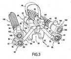
figure 3 représente un deuxième exemple d'implant selon l'invention ; - la
figure 4 est une vue arrière selon la flèche IV, de l'implant de lafigure 3 , une fois celui-ci mis en place entre les vertèbres L5 et S1 ; - la
figure 5 est une coupe de l'implant de lafigure 4 selon le plan médian M et suivant les flèches V ; - la
figure 6 est une coupe axiale d'une tête de vis pédiculaire utilisée dans l'implant de lafigure 2 ; - la
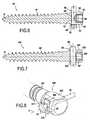
figure 7 est une coupe axiale d'une tête de vis pédiculaire utilisée dans l'implant desfigures 3 à 5 ; - la
figure 8 est une coupe axiale d'un autre exemple de tête de vis pédiculaire pouvant être utilisé ; - la
figure 9 est une vue arrière représentant un troisième exemple d'implant selon l'invention, mis en place entre les vertèbres L5 et S1 ; et - la
figure 10 est une coupe selon le plan X montrant le lien souple et le crochet de l'implant de lafigure 9 .
- the
figure 1 schematically represents the anatomy of the lumbosacral region of the spine; - the
figure 2 represents a first example of an implant according to the invention; - the
figure 3 represents a second example of an implant according to the invention; - the
figure 4 is a rear view along arrow IV, of the implant of thefigure 3 once it is placed between the vertebrae L5 and S1; - the
figure 5 is a section of the implant of thefigure 4 along the median plane M and following the arrows V; - the
figure 6 is an axial section of a pedicle screw head used in the implant of thefigure 2 ; - the
figure 7 is an axial section of a pedicle screw head used in the implant ofFigures 3 to 5 ; - the
figure 8 is an axial section of another example of a pedicle screw head that can be used; - the
figure 9 is a rear view showing a third example of an implant according to the invention, placed between the vertebrae L5 and S1; and - the
figure 10 is a section along the X plane showing the flexible link and the hook of the implant of thefigure 9 .
La cinquième vertèbre lombaire L5 et la vertèbre supérieure du sacrum S1 sont représentées schématiquement sur la
La partie supérieure de la vertèbre S1 forme un arc postérieur 14. La face interne de l'arc postérieur 14 fait face au corps vertébral du sacrum, elle est concave et définit avec le corps vertébral un orifice traversé par la moelle épinière (non représentée), appelé trou rachidien 16.The upper part of the vertebra S1 forms a
Le même exemple de cale 20 est utilisé pour les deux exemples d'implant représentés sur les
Cette cale 20 est destinée à être insérée entre l'épineuse 10 et l'arc postérieur 14 et permet de limiter le rapprochement de l'épineuse 10 et de l'arc postérieur 14 lors de l'extension du rachis. Elle est réalisée en matériau biocompatible, par exemple un biopolymère comme le polyétheréthercétone (PEEK).This
Les directions haut, bas, avant, arrière, droite et gauche sont définies ci-après par référence au positionnement de la cale sur le rachis, la face avant de la cale étant tournée vers le ventre de l'individu porteur de la cale. Le plan médian M de la cale 20 correspond sensiblement au plan sagittal du rachis lorsque la cale est mise en place, il coupe les faces supérieure 22, inférieure 24, antérieure 26 et postérieure 28 de cette cale.The directions up, down, forward, back, right and left are defined below with reference to the positioning of the wedge on the spine, the front face of the wedge being turned towards the belly of the individual carrying the hold. The median plane M of the
Une rainure 30, orientée suivant le plan médian M de la cale, est ménagée sur la face supérieure 22 de la cale 20 pour recevoir l'épineuse 10 de la vertèbre L5. La rainure 30 débouche sur les faces antérieure 26 et postérieure 28 de la cale.A
Par ailleurs, un logement 36 longitudinal, orienté orthogonalement à ladite rainure 30, est ménagé au niveau de la face inférieure 24 de la cale, pour recevoir la partie supérieure de la vertèbre S1. La cale 20 peut ainsi reposer directement sur la vertèbre S1.Furthermore, a
La cale 20 présente à son extrémité inférieure deux extensions 32 dans le prolongement de la face postérieure 28. La cale 20 comprend, en outre, une patte 34 dans le prolongement de la face antérieure 26, qui s'étend en regard de l'espace laissé entre les extensions 32. La patte 34 et les extensions 32 définissent entre elles le logement longitudinal 36 précité. Les extensions 32 sont écartées de manière à pouvoir loger entre elles la bosse résiduelle 12 de la vertèbre S1.The
Les exemples d'implant représentés comprennent également des moyens d'attache pour attacher la cale 20 à l'épineuse 10 de la vertèbre L5. Avantageusement, ces moyens d'attache comprennent une sangle 46 solidaire de la cale 20 et susceptible d'être serrée autour de l'épineuse 10 de la vertèbre L5 pour retenir cette épineuse 10 dans la rainure 30 ménagée sur la face supérieure 22 de la cale. Une extrémité de la sangle 46 est fixée à la cale 20, d'un coté de la rainure 30, tandis que l'autre extrémité peut être passée dans un système d'attache 42 solidaire de la cale 20, situé de l'autre côté de rainure 30. Le système d'attache 42 peut être amovible.The implant examples shown also include attachment means for attaching the
Lors de la mise en place de la cale 20, la sangle 46 est passée autour de l'épineuse 10 puis passée dans le système d'attache 42. Ce système 42 peut être autobloquant de sorte qu'une fois la sangle 46 passée dans le système dans une direction et serrée autour de l'épineuse 10, le système 42 empêche la sangle de glisser dans la direction opposée.When placing the
La cale 20 comprend en outre un crochet 21 formé sur sa face postérieure 28 et qui sera décrit plus en détail ci-après.The
En référence à la
Cet implant comprend une cale 20 du type précité, équipée de moyens d'attache, d'un lien souple 50 et deux vis pédiculaires 60 situées de chaque côté de la cale 20.This implant comprises a
Les vis pédiculaires 60 comprennent un corps de vis 61 apte à être vissé dans le sacrum et une tête de vis 62 destinée à rester, au moins en partie, à l'extérieur du sacrum. Cette tête de vis 62 présente un évidement 63 apte à recevoir une portion d'extrémité 52 du lien souple 50. Dans l'exemple, cet évidement est une rainure ménagée sur la face d'extrémité 64 de la tête de vis. Cette rainure traverse radialement (c'est-à-dire orthogonalement à l'axe A de la vis) la tête de vis 60, d'un bord à l'autre. Cette rainure est délimitée par deux parois latérales opposées 65 et une paroi de fond 66 (voir
Le lien souple 50 présente, de préférence, une certaine élasticité. Il est par exemple formé d'au moins une tresse tubulaire réalisée à partir de fils de matériaux biocompatibles comme le polyéthylène. Le tressage et, surtout, les propriétés intrinsèques du polyéthylène assurent l'élasticité du lien souple. Les deux portions d'extrémité 52 du lien souple 50 sont destinées à être fixées aux têtes de vis 62. Par ailleurs, une portion intermédiaire 54 du lien souple 20 est apte à coopérer avec un système de liaison présent sur la cale 20. De préférence, cette portion intermédiaire 54 est sensiblement médiane.The
Dans l'exemple, le crochet 21 situé à l'arrière de la cale 20 fait office de système de liaison. Ce crochet 21 est réalisé en une seule pièce avec la cale 20 et fait saillie sur la face postérieure 28 de la cale. Il est tourné vers le haut, de manière à retenir la portion intermédiaire 54 du lien souple 50. D'autres systèmes de liaison pourraient cependant être envisagés comme une rainure ménagée à l'arrière de la cale 20, par exemple sur sa face postérieure 28, ou un perçage traversant ladite cale.In the example, the
La mise en place de l'implant se déroule comme suit. D'abord, on fixe les vis 60 sur le sacrum. Ensuite, on engage les portions d'extrémité 52 du lien souple 50 dans les évidements 63 des têtes de vis 62 et la portion intermédiaire 54 du lien souple 50 dans le crochet 21. Pour s'assurer que les portions d'extrémité 52 du lien souple restent dans les évidements 63 avant d'être fixées définitivement à l'aide de la vis de serrage 68, le lien souple présente à ses extrémités des excroissances 55 de dimensions supérieures à la largeur de l'évidement 63. En outre, des rondelles 56 peuvent être prévues entre les excroissances 55 et les tête de vis 62. Enfin, on fixe chaque portion d'extrémité 52 du lien souple à sa tête de vis 62 respective en serrant la vis de serrage 68. Cette vis vient presser le lien souple contre la paroi de fond 66 de l'évidement 63, pour le maintenir en position (voir
La tension du lien souple 50 peut être réglée en tirant sur les portions d'extrémité 52 du lien souple pour les éloigner de la cale 20, avant de les fixer définitivement à l'aide des vis de serrage 68 à l'intérieur des évidements 63.The tension of the
Une fois sous tension, le lien souple 50 exerce sur la cale des forces de rappel ayant une résultante dirigée vers la vertèbre S1. Pour que cette résultante ait une composante verticale dirigée vers le bas, suffisamment importante, il est préférable que les têtes de vis 62 soient situées suffisamment en dessous du crochet 21. En outre, on peut faire en sorte que la portion intermédiaire 54 du lien souple 50 soit située plus en arrière que les portions d'extrémité 52 du lien souple (c'est-à-dire plus en arrière que les têtes de vis 62). Ceci permet à la résultante des forces de rappel d'avoir une composante horizontale dirigée vers le rachis (c'est-à-dire vers l'avant de la cale 20). Une telle composante horizontale empêche la cale 20 de sortir par l'arrière de l'espace intervertébral L5-S1.Once under tension, the
En référence aux
D'autre part, comme représenté sur la
Ce deuxième exemple d'implant permet, en faisant coulisser la tige 84 dans l'évidement 163, de régler la tension du lien souple 50. Ainsi, lors de l'installation de l'implant, on peut d'abord fixer la portion intermédiaire 54 du lien souple à la cale 20 et les portions d'extrémité 52 du lien souple au système de fixation 80, en effectuant un premier réglage de la tension du lien souple et, ensuite, fixer les tiges 84 dans leur position définitive pour effectuer, si nécessaire, un deuxième réglage de la tension du lien souple.This second example of an implant makes it possible, by sliding the
En référence à la
Le contour du trou 263 est tel que la plaquette 270 et le lien souple 50 peuvent traverser le trou 263 lorsque la plaquette 270 est inclinée sensiblement suivant l'axe H du trou, et tel que cette même plaquette 270 ne puisse pas traverser le trou 263 lorsqu'elle est sensiblement perpendiculaire à l'axe H. Par exemple, la plaquette 270 et le contour du trou 263 présentent tous les deux une forme rectangulaire, la largeur de la plaquette étant inférieure à la largeur du contour du trou tandis que la longueur de la plaquette est supérieure à la diagonale du contour du trou. Dans cet exemple, la plaquette 270 doit être inclinée dans le sens de la longueur pour traverser le trou 263.The contour of the
Pour fixer le lien souple 50 à la tête de vis 262, on passe la plaquette 270, inclinée suivant l'axe H, et la portion d'extrémité 52 du lien souple à travers le trou 263. Une fois le trou 263 traversé, on rabat la plaquette 270 dans une position perpendiculaire à l'axe H. La plaquette 270 a d'ailleurs tendance à revenir dans cette dernière position naturellement. Le lien souple 50 étant sous-tension, la plaquette 270 est plaquée contre la tête de vis 262 dans sa position perpendiculaire à l'axe H de sorte que la portion d'extrémité 52 (retenue par l'excroissance 55 et la plaquette 270 du lien souple 50) ne peut plus s'échapper de la tête de vis 262. Pour faciliter l'inclinaison de la plaquette 270 par rapport au lien souple 50, le perçage 271 à l'intérieur duquel est enfilé le lien souple 50 est de forme oblongue.To fix the
Contrairement aux systèmes de fixation représentés sur les
En référence à la
De préférence, on accroche un crochet 90 dans chacun des deux trous de conjugaison 11 situés entre les vertèbres S1 et S2, c'est-à-dire les trous 11 situés le plus près de la cale 20.Preferably, a
Chaque portion d'extrémité 52 du lien souple 50 est fixée à un crochet par un système de fixation. Dans l'exemple de la
Pour fixer les extrémités 52 du lien souple au crochet 90, d'autres systèmes de fixation pourraient, bien entendu, être envisagés. Ainsi, on pourrait utiliser des systèmes analogues à ceux précédemment décrits et représentés sur les
On notera que quelque soit le mode de réalisation retenu, on obtient une mise sous tension du lien souple 50 de manière à tirer la cale 20 vers le bas.It will be noted that, whatever the embodiment chosen, the
Dans les modes de réalisation des
Dans l'exemple de la
Dans l'exemple de la
Dans l'exemple de la
Claims (10)
- An intervertebral implant for the lumbo-sacral joint, the implant comprising a spacer (20) suitable for being placed between the fifth lumbar vertebra L5 and the vertebra S1 of the sacrum that is articulated to the vertebra L5, the implant beingcharacterized in that it includes a flexible tie (50) having end portions (52) that can be fastened to the sacrum with the help of fasteners, the flexible tie presenting an intermediate portion (54) suitable for co-operating with a connection system provided on said spacer (20) in such a manner that the flexible tie connects the spacer to the sacrum.
- An intervertebral implant for the lumbo-sacral joint, according to claim 1,characterized in that said fasteners comprise pedicular screws (60, 160) that are suitable for being anchored in the sacrum, each presenting a screw head (62, 162) fitted with a fastening system, each end portion (52) of the flexible tie being fastened to said screw head with the help of said fastening system.
- An intervertebral implant for the lumbo-sacral joint, according to claim 2,characterized in that said fastening system comprises a body portion (62, 82) presenting a recess (63, 83) suitable for receiving an end portion (52) of said flexible tie and a clamping screw (68, 88) for clamping the flexible tie inside said recess (63, 83).
- An intervertebral implant for the lumbo-sacral joint, according to claim 3,characterized in that the screw head (62) of each pedicular screw (60) forms said body portion of the fastening system.
- An intervertebral implant for the lumbo-sacral joint, according to claim 3,characterized in that said body portion (82) is extended by a rod (84), the screw heads (162) of the pedicular screws (160) each presenting a respective recess (163) suitable for receiving said rod (84) and a clamping screw (168) for fastening said rod (84) inside said recess (163).
- An intervertebral implant for the lumbo-sacral joint, according to claim 1,characterized in that said fasteners comprise hooks (90) suitable for being hooked in the intervertebral foramens of the sacrum, each end portion (52) of the flexible tie being fastened to a said hook (90).
- An intervertebral implant for the lumbo-sacral joint, according to any preceding claim,characterized in that said connection system comprises a hook (21) formed on said spacer (20).
- An intervertebral implant for the lumbo-sacral joint, according to any preceding claim,characterized in that the end portions of the flexible tie (50) are movable relative to said fasteners and can be pulled away from said spacer (20) to put said flexible tie under tension, prior to being prevented from moving relative to the fasteners, the flexible tie (50) then exerting return force on the spacer (20) towards said vertebra S1.
- An intervertebral implant for the lumbo-sacral joint, according to any preceding claim,characterized in that said spacer (20) presents a top face (22) and an opposite bottom face (24),in that a groove (30) extending along the midplane (M) of the spacer is formed in the top face (22) to receive the spinous process (10) of said vertebra L5, andin that a longitudinal housing (36) extending orthogonally to said groove (30) is formed in the bottom face (24) to receive the top portion of the vertebra S1.
- An intervertebral implant for the lumbo-sacral joint, according to any preceding claim,characterized in that it further comprises an attachment (46) for attaching the spacer (20) to the spinous process (10) of the vertebra L5.
Applications Claiming Priority (2)
| Application Number | Priority Date | Filing Date | Title |
|---|---|---|---|
| FR0508767AFR2889937B1 (en) | 2005-08-26 | 2005-08-26 | INTERVERTEBRAL IMPLANT FOR LOMBO-SACRED JOINT |
| PCT/FR2006/050811WO2007023240A2 (en) | 2005-08-26 | 2006-08-25 | Intervertebral implant for the lumbosacral joint |
Publications (2)
| Publication Number | Publication Date |
|---|---|
| EP1924210A2 EP1924210A2 (en) | 2008-05-28 |
| EP1924210B1true EP1924210B1 (en) | 2009-10-07 |
Family
ID=36383752
Family Applications (1)
| Application Number | Title | Priority Date | Filing Date |
|---|---|---|---|
| EP06808251ANot-in-forceEP1924210B1 (en) | 2005-08-26 | 2006-08-25 | Intervertebral implant for the lumbosacral joint |
Country Status (8)
| Country | Link |
|---|---|
| US (1) | US8092497B2 (en) |
| EP (1) | EP1924210B1 (en) |
| JP (1) | JP2009505706A (en) |
| AU (1) | AU2006283410B2 (en) |
| DE (1) | DE602006009684D1 (en) |
| ES (1) | ES2334715T3 (en) |
| FR (1) | FR2889937B1 (en) |
| WO (1) | WO2007023240A2 (en) |
Cited By (1)
| Publication number | Priority date | Publication date | Assignee | Title |
|---|---|---|---|---|
| US9173746B2 (en) | 2005-09-27 | 2015-11-03 | Paradigm Spine, Llc | Interspinous vertebral stabilization devices |
Families Citing this family (62)
| Publication number | Priority date | Publication date | Assignee | Title |
|---|---|---|---|---|
| FR2842724B1 (en) | 2002-07-23 | 2005-05-27 | Spine Next Sa | VERTEBRAL FASTENING SYSTEM |
| US7627343B2 (en)* | 2003-04-25 | 2009-12-01 | Apple Inc. | Media player system |
| US7846183B2 (en) | 2004-02-06 | 2010-12-07 | Spinal Elements, Inc. | Vertebral facet joint prosthesis and method of fixation |
| US8034085B2 (en) | 2004-05-28 | 2011-10-11 | Depuy Spine, Inc. | Non-fusion spinal correction systems and methods |
| US9504583B2 (en) | 2004-06-10 | 2016-11-29 | Spinal Elements, Inc. | Implant and method for facet immobilization |
| US8241330B2 (en) | 2007-01-11 | 2012-08-14 | Lanx, Inc. | Spinous process implants and associated methods |
| US9055981B2 (en) | 2004-10-25 | 2015-06-16 | Lanx, Inc. | Spinal implants and methods |
| US7909826B2 (en)* | 2005-03-24 | 2011-03-22 | Depuy Spine, Inc. | Low profile spinal tethering methods |
| US8066742B2 (en)* | 2005-03-31 | 2011-11-29 | Warsaw Orthopedic, Inc. | Intervertebral prosthetic device for spinal stabilization and method of implanting same |
| FR2890850B1 (en) | 2005-09-20 | 2009-04-17 | Abbott Spine Sa | VERTEBRAL FASTENING SYSTEM |
| FR2890851B1 (en) | 2005-09-21 | 2008-06-20 | Abbott Spine Sa | ANCILLARY TO TENSION A FLEXIBLE LINK. |
| US20070233089A1 (en)* | 2006-02-17 | 2007-10-04 | Endius, Inc. | Systems and methods for reducing adjacent level disc disease |
| JP5210305B2 (en)* | 2006-06-16 | 2013-06-12 | アルファテック スパイン, インコーポレイテッド | Spinal screw assembly system, system for implanting spinal screw assembly |
| EP2047813A1 (en) | 2007-10-11 | 2009-04-15 | Abbott Spine | Bone fixing system and method of use |
| US8740941B2 (en)* | 2006-11-10 | 2014-06-03 | Lanx, Inc. | Pedicle based spinal stabilization with adjacent vertebral body support |
| US7850732B2 (en)* | 2006-12-11 | 2010-12-14 | Warsaw Orthopedic, Inc. | Sacral prosthesis and surgical method |
| US9265532B2 (en) | 2007-01-11 | 2016-02-23 | Lanx, Inc. | Interspinous implants and methods |
| US9247968B2 (en) | 2007-01-11 | 2016-02-02 | Lanx, Inc. | Spinous process implants and associated methods |
| US8992533B2 (en) | 2007-02-22 | 2015-03-31 | Spinal Elements, Inc. | Vertebral facet joint drill and method of use |
| EP2813190B1 (en) | 2007-02-22 | 2017-04-26 | Spinal Elements, Inc. | Vertebral facet joint drill |
| FR2921248A1 (en) | 2007-09-25 | 2009-03-27 | Abbott Spine Sa | DEVICE FOR TIGHTENING TWO PORTIONS OF A BRAID AND INTERVERTEBRAL IMPLANT COMPRISING A BILGE, A BRAID AND A SUCH TIGHTENING DEVICE |
| US8128635B2 (en) | 2007-10-23 | 2012-03-06 | Zimmer Spine S.A.S. | Bone fixation tensioning tool and method |
| ATE536824T1 (en) | 2007-10-23 | 2011-12-15 | Zimmer Spine | FASTENING DEVICES AND STABILIZATION SYSTEMS WITH THESE FASTENING DEVICES |
| US20090204151A1 (en)* | 2008-02-07 | 2009-08-13 | Scott Bracken | Spinal implant device, procedure and system |
| US9301788B2 (en)* | 2008-04-10 | 2016-04-05 | Life Spine, Inc. | Adjustable spine distraction implant |
| ATE515239T1 (en)* | 2008-04-24 | 2011-07-15 | Zimmer Spine | SYSTEM FOR STABILIZING AT LEAST ONE SECTION OF THE SPINE |
| EP2303163B1 (en) | 2008-05-20 | 2011-11-23 | Zimmer Spine | System for stabilizing at least three vertebrae |
| EP2138122A1 (en) | 2008-06-25 | 2009-12-30 | Abbott Spine | Stabilization system between a sacrum and a lumbar vertebra |
| US20110184470A1 (en)* | 2008-08-07 | 2011-07-28 | K2M, Inc. | Bone screw assembly |
| US20110137345A1 (en)* | 2009-03-18 | 2011-06-09 | Caleb Stoll | Posterior lumbar fusion |
| US20110029086A1 (en)* | 2009-07-29 | 2011-02-03 | Glazer Paul A | Lumbar jack implant |
| US8574271B2 (en)* | 2009-07-29 | 2013-11-05 | Paul Andrew Glazer | Fixation plate screw retention |
| EP2351534B1 (en)* | 2010-02-01 | 2012-08-22 | Zimmer Spine | Intervertebral device |
| BR112012020550A2 (en)* | 2010-03-04 | 2017-06-27 | Synthes Gmbh | expandable laminar implant for spinal fusion. |
| FR2960767A1 (en)* | 2010-06-04 | 2011-12-09 | Hpi | Device for fixing prosthesis i.e. interspinous implant, between lumbar vertebra and sacral vertebra during surgery of spinal column, has artificial apophysis comprising projection cooperating with interspinous implant |
| WO2012048131A2 (en)* | 2010-10-06 | 2012-04-12 | Simpirica Spine, Inc. | Device and accessories for limiting flexion |
| US8496689B2 (en) | 2011-02-23 | 2013-07-30 | Farzad Massoudi | Spinal implant device with fusion cage and fixation plates and method of implanting |
| USD724733S1 (en) | 2011-02-24 | 2015-03-17 | Spinal Elements, Inc. | Interbody bone implant |
| US8740949B2 (en) | 2011-02-24 | 2014-06-03 | Spinal Elements, Inc. | Methods and apparatus for stabilizing bone |
| US9271765B2 (en) | 2011-02-24 | 2016-03-01 | Spinal Elements, Inc. | Vertebral facet joint fusion implant and method for fusion |
| US8425560B2 (en) | 2011-03-09 | 2013-04-23 | Farzad Massoudi | Spinal implant device with fixation plates and lag screws and method of implanting |
| FR2978658B1 (en)* | 2011-08-02 | 2013-09-06 | Gilles Dubois | INTERVERTEBRAL DYNAMIC FASTENING IMPLANT |
| WO2013040456A1 (en)* | 2011-09-14 | 2013-03-21 | Band-Lok, Llc | Tether clamp and implantation system |
| US11812923B2 (en) | 2011-10-07 | 2023-11-14 | Alan Villavicencio | Spinal fixation device |
| USD739935S1 (en) | 2011-10-26 | 2015-09-29 | Spinal Elements, Inc. | Interbody bone implant |
| US10548644B2 (en) | 2013-03-05 | 2020-02-04 | Globus Medical, Inc. | Elastic member clamps |
| USD765853S1 (en) | 2013-03-14 | 2016-09-06 | Spinal Elements, Inc. | Flexible elongate member with a portion configured to receive a bone anchor |
| US9820784B2 (en) | 2013-03-14 | 2017-11-21 | Spinal Elements, Inc. | Apparatus for spinal fixation and methods of use |
| US9421044B2 (en) | 2013-03-14 | 2016-08-23 | Spinal Elements, Inc. | Apparatus for bone stabilization and distraction and methods of use |
| US11213325B2 (en)* | 2013-03-15 | 2022-01-04 | Jcbd, Llc | Spinal stabilization system with adjustable interlaminar devices |
| US9510872B2 (en)* | 2013-03-15 | 2016-12-06 | Jcbd, Llc | Spinal stabilization system |
| US9456855B2 (en) | 2013-09-27 | 2016-10-04 | Spinal Elements, Inc. | Method of placing an implant between bone portions |
| US9839450B2 (en) | 2013-09-27 | 2017-12-12 | Spinal Elements, Inc. | Device and method for reinforcement of a facet |
| US11478275B2 (en) | 2014-09-17 | 2022-10-25 | Spinal Elements, Inc. | Flexible fastening band connector |
| US9931138B2 (en) | 2014-10-15 | 2018-04-03 | Globus Medical, Inc. | Orthopedic extendable rods |
| AU2016212009C1 (en) | 2015-01-27 | 2021-02-25 | Spinal Elements, Inc. | Facet joint implant |
| CN109528366B (en)* | 2018-12-19 | 2024-03-26 | 中国人民解放军第二军医大学第二附属医院 | Displacement-preventing vertebral body prosthesis |
| CN109528280B (en)* | 2018-12-19 | 2023-12-29 | 中国人民解放军第二军医大学第二附属医院 | Anti-displacement device and anti-displacement system for internal fixation |
| US11457959B2 (en) | 2019-05-22 | 2022-10-04 | Spinal Elements, Inc. | Bone tie and bone tie inserter |
| BR112021022695A2 (en) | 2019-05-22 | 2021-12-28 | Spinal Elements Inc | Bone tethering and bone tethering inserter |
| WO2021163313A1 (en) | 2020-02-14 | 2021-08-19 | Spinal Elements, Inc. | Bone tie methods |
| US12369952B2 (en) | 2021-12-10 | 2025-07-29 | Spinal Elements, Inc. | Bone tie and portal |
Family Cites Families (5)
| Publication number | Priority date | Publication date | Assignee | Title |
|---|---|---|---|---|
| FR2806616B1 (en)* | 2000-03-21 | 2003-04-11 | Cousin Biotech | INTERPINEUSE SHIM AND FASTENING DEVICE ON THE SACRUM |
| FR2822051B1 (en)* | 2001-03-13 | 2004-02-27 | Spine Next Sa | INTERVERTEBRAL IMPLANT WITH SELF-LOCKING ATTACHMENT |
| ITFI20030084A1 (en)* | 2003-03-28 | 2004-09-29 | Cousin Biotech S A S | INTERLAMINARY VERTEBRAL PROSTHESIS |
| FR2858929B1 (en)* | 2003-08-21 | 2005-09-30 | Spine Next Sa | "INTERVERTEBRAL IMPLANT FOR LOMBO-SACRED JOINT" |
| US7951169B2 (en)* | 2005-06-10 | 2011-05-31 | Depuy Spine, Inc. | Posterior dynamic stabilization cross connectors |
- 2005
- 2005-08-26FRFR0508767Apatent/FR2889937B1/ennot_activeExpired - Lifetime
- 2006
- 2006-08-25AUAU2006283410Apatent/AU2006283410B2/ennot_activeCeased
- 2006-08-25JPJP2008527491Apatent/JP2009505706A/ennot_activeWithdrawn
- 2006-08-25USUS12/064,935patent/US8092497B2/ennot_activeExpired - Fee Related
- 2006-08-25DEDE602006009684Tpatent/DE602006009684D1/enactiveActive
- 2006-08-25WOPCT/FR2006/050811patent/WO2007023240A2/enactiveApplication Filing
- 2006-08-25ESES06808251Tpatent/ES2334715T3/enactiveActive
- 2006-08-25EPEP06808251Apatent/EP1924210B1/ennot_activeNot-in-force
Cited By (1)
| Publication number | Priority date | Publication date | Assignee | Title |
|---|---|---|---|---|
| US9173746B2 (en) | 2005-09-27 | 2015-11-03 | Paradigm Spine, Llc | Interspinous vertebral stabilization devices |
Also Published As
| Publication number | Publication date |
|---|---|
| US8092497B2 (en) | 2012-01-10 |
| DE602006009684D1 (en) | 2009-11-19 |
| AU2006283410A1 (en) | 2007-03-01 |
| WO2007023240A3 (en) | 2007-04-12 |
| AU2006283410B2 (en) | 2009-10-29 |
| US20090018662A1 (en) | 2009-01-15 |
| FR2889937A1 (en) | 2007-03-02 |
| WO2007023240A2 (en) | 2007-03-01 |
| FR2889937B1 (en) | 2007-11-09 |
| EP1924210A2 (en) | 2008-05-28 |
| JP2009505706A (en) | 2009-02-12 |
| ES2334715T3 (en) | 2010-03-15 |
Similar Documents
| Publication | Publication Date | Title |
|---|---|---|
| EP1924210B1 (en) | Intervertebral implant for the lumbosacral joint | |
| EP1656075B1 (en) | Intervertebral implant for the lumbosacral joint | |
| EP2555697B1 (en) | Transverse connection system and device for the vertebral column | |
| EP1865863B1 (en) | Intervertebral implant for lumbrosacral joint | |
| EP1675513B1 (en) | Inter-blade support | |
| EP1926444B2 (en) | Vertebral fixing systemw | |
| EP2521500B1 (en) | Vertebral attachment device | |
| EP1795136B1 (en) | Apparatus for dynamic stabilisation of the spine | |
| FR2651992A1 (en) | Implant for spinal osteosynthesis of the anterior dorsolumbar vertebrae intended for correction of kyphoses | |
| EP1113758A1 (en) | Posterior backbone osteosynthesis device | |
| CH653239A5 (en) | HOOK FOR THE TREATMENT OF VERTEBRAL CONDITIONS. | |
| FR2918555A1 (en) | DEVICE AND SYSTEM FOR TRANSVERSE SPINACH CONNECTION | |
| EP1138268A1 (en) | Device for the fixation of an interspinous wedge on the sacrum | |
| FR2902639A1 (en) | Patient`s lumbo-sacral region stabilizing implant, has U-shaped clamps respectively anchored on upper edges of plates of sacral vertebra and provided on both sides of branch of central body that is made of elastic material | |
| WO2008034996A1 (en) | Lumbar inter-spine prosthesis and applications thereof | |
| FR2989264A1 (en) | MATERIAL OF VERTEBRAL OSTEOSYNTHESIS | |
| FR2861285A1 (en) | Inter-vertebral support has anterior zone with grooves for vertebral plates and porterior zone with two transverse projections and thrust zone | |
| WO2013132180A1 (en) | Lumbar support belt | |
| EP3082630B1 (en) | Vertebral fixation device with double fastening, system for blocking a loop with such a device | |
| FR2704424A1 (en) | Cervical orthesis with adjustable cervico-occipital support | |
| FR2890849A1 (en) | Vertebral fixing system for e.g. scoliosis treatment, has connection part defining through path for elongated flexible link such that portions of link are engaged with path for defining link part and free ends | |
| FR2918261A1 (en) | DEVICE FOR CONNECTING AT LEAST THREE VERTEBRATES BETWEEN THEM |
Legal Events
| Date | Code | Title | Description |
|---|---|---|---|
| PUAI | Public reference made under article 153(3) epc to a published international application that has entered the european phase | Free format text:ORIGINAL CODE: 0009012 | |
| 17P | Request for examination filed | Effective date:20080227 | |
| AK | Designated contracting states | Kind code of ref document:A2 Designated state(s):DE ES FR GB IT | |
| RBV | Designated contracting states (corrected) | Designated state(s):DE ES FR GB IT | |
| GRAP | Despatch of communication of intention to grant a patent | Free format text:ORIGINAL CODE: EPIDOSNIGR1 | |
| GRAS | Grant fee paid | Free format text:ORIGINAL CODE: EPIDOSNIGR3 | |
| RAP1 | Party data changed (applicant data changed or rights of an application transferred) | Owner name:ZIMMER SPINE | |
| GRAA | (expected) grant | Free format text:ORIGINAL CODE: 0009210 | |
| AK | Designated contracting states | Kind code of ref document:B1 Designated state(s):DE ES FR GB IT | |
| REG | Reference to a national code | Ref country code:GB Ref legal event code:FG4D Free format text:NOT ENGLISH | |
| REF | Corresponds to: | Ref document number:602006009684 Country of ref document:DE Date of ref document:20091119 Kind code of ref document:P | |
| REG | Reference to a national code | Ref country code:ES Ref legal event code:FG2A Ref document number:2334715 Country of ref document:ES Kind code of ref document:T3 | |
| PLBE | No opposition filed within time limit | Free format text:ORIGINAL CODE: 0009261 | |
| STAA | Information on the status of an ep patent application or granted ep patent | Free format text:STATUS: NO OPPOSITION FILED WITHIN TIME LIMIT | |
| 26N | No opposition filed | Effective date:20100708 | |
| PGFP | Annual fee paid to national office [announced via postgrant information from national office to epo] | Ref country code:ES Payment date:20100818 Year of fee payment:5 | |
| PGFP | Annual fee paid to national office [announced via postgrant information from national office to epo] | Ref country code:IT Payment date:20110818 Year of fee payment:6 | |
| PG25 | Lapsed in a contracting state [announced via postgrant information from national office to epo] | Ref country code:IT Free format text:LAPSE BECAUSE OF NON-PAYMENT OF DUE FEES Effective date:20120825 | |
| REG | Reference to a national code | Ref country code:ES Ref legal event code:FD2A Effective date:20131029 | |
| PG25 | Lapsed in a contracting state [announced via postgrant information from national office to epo] | Ref country code:ES Free format text:LAPSE BECAUSE OF NON-PAYMENT OF DUE FEES Effective date:20110826 | |
| REG | Reference to a national code | Ref country code:FR Ref legal event code:PLFP Year of fee payment:11 | |
| REG | Reference to a national code | Ref country code:FR Ref legal event code:PLFP Year of fee payment:12 | |
| PGFP | Annual fee paid to national office [announced via postgrant information from national office to epo] | Ref country code:GB Payment date:20170823 Year of fee payment:12 Ref country code:DE Payment date:20170822 Year of fee payment:12 Ref country code:FR Payment date:20170714 Year of fee payment:12 | |
| REG | Reference to a national code | Ref country code:DE Ref legal event code:R119 Ref document number:602006009684 Country of ref document:DE | |
| GBPC | Gb: european patent ceased through non-payment of renewal fee | Effective date:20180825 | |
| PG25 | Lapsed in a contracting state [announced via postgrant information from national office to epo] | Ref country code:DE Free format text:LAPSE BECAUSE OF NON-PAYMENT OF DUE FEES Effective date:20190301 | |
| PG25 | Lapsed in a contracting state [announced via postgrant information from national office to epo] | Ref country code:FR Free format text:LAPSE BECAUSE OF NON-PAYMENT OF DUE FEES Effective date:20180831 | |
| PG25 | Lapsed in a contracting state [announced via postgrant information from national office to epo] | Ref country code:GB Free format text:LAPSE BECAUSE OF NON-PAYMENT OF DUE FEES Effective date:20180825 |