EP1923595B1 - Vibration damper with amplitude-dependent damping force - Google Patents
Vibration damper with amplitude-dependent damping forceDownload PDFInfo
- Publication number
- EP1923595B1 EP1923595B1EP20070021522EP07021522AEP1923595B1EP 1923595 B1EP1923595 B1EP 1923595B1EP 20070021522EP20070021522EP 20070021522EP 07021522 AEP07021522 AEP 07021522AEP 1923595 B1EP1923595 B1EP 1923595B1
- Authority
- EP
- European Patent Office
- Prior art keywords
- piston rod
- vibration damper
- valve
- cylinder
- damper according
- Prior art date
- Legal status (The legal status is an assumption and is not a legal conclusion. Google has not performed a legal analysis and makes no representation as to the accuracy of the status listed.)
- Not-in-force
Links
- 238000013016dampingMethods0.000titleclaimsdescription30
- 230000001419dependent effectEffects0.000titleclaimsdescription13
- 239000012530fluidSubstances0.000claimsdescription14
- 230000007704transitionEffects0.000claimsdescription3
- 238000005253claddingMethods0.000description3
- 238000007789sealingMethods0.000description3
- 238000010276constructionMethods0.000description1
- 230000000694effectsEffects0.000description1
Images


Classifications
- F—MECHANICAL ENGINEERING; LIGHTING; HEATING; WEAPONS; BLASTING
- F16—ENGINEERING ELEMENTS AND UNITS; GENERAL MEASURES FOR PRODUCING AND MAINTAINING EFFECTIVE FUNCTIONING OF MACHINES OR INSTALLATIONS; THERMAL INSULATION IN GENERAL
- F16F—SPRINGS; SHOCK-ABSORBERS; MEANS FOR DAMPING VIBRATION
- F16F9/00—Springs, vibration-dampers, shock-absorbers, or similarly-constructed movement-dampers using a fluid or the equivalent as damping medium
- F16F9/10—Springs, vibration-dampers, shock-absorbers, or similarly-constructed movement-dampers using a fluid or the equivalent as damping medium using liquid only; using a fluid of which the nature is immaterial
- F16F9/14—Devices with one or more members, e.g. pistons, vanes, moving to and fro in chambers and using throttling effect
- F16F9/16—Devices with one or more members, e.g. pistons, vanes, moving to and fro in chambers and using throttling effect involving only straight-line movement of the effective parts
- F16F9/18—Devices with one or more members, e.g. pistons, vanes, moving to and fro in chambers and using throttling effect involving only straight-line movement of the effective parts with a closed cylinder and a piston separating two or more working spaces therein
- F16F9/20—Devices with one or more members, e.g. pistons, vanes, moving to and fro in chambers and using throttling effect involving only straight-line movement of the effective parts with a closed cylinder and a piston separating two or more working spaces therein with the piston-rod extending through both ends of the cylinder, e.g. constant-volume dampers
- F—MECHANICAL ENGINEERING; LIGHTING; HEATING; WEAPONS; BLASTING
- F16—ENGINEERING ELEMENTS AND UNITS; GENERAL MEASURES FOR PRODUCING AND MAINTAINING EFFECTIVE FUNCTIONING OF MACHINES OR INSTALLATIONS; THERMAL INSULATION IN GENERAL
- F16F—SPRINGS; SHOCK-ABSORBERS; MEANS FOR DAMPING VIBRATION
- F16F9/00—Springs, vibration-dampers, shock-absorbers, or similarly-constructed movement-dampers using a fluid or the equivalent as damping medium
- F16F9/32—Details
- F16F9/48—Arrangements for providing different damping effects at different parts of the stroke
- F16F9/49—Stops limiting fluid passage, e.g. hydraulic stops or elastomeric elements inside the cylinder which contribute to changes in fluid damping
Definitions
- the inventionrelates to a vibration damper with amplitude-dependent damping force according to the preamble of patent claim 1.
- the effect of the amplitude-dependent damping forceis limited to a very small stroke range.
- the frictional force-dependent valve ringcloses the connection opening outside of said stroke range both in an extension as well as a retraction movement of the piston rod.
- the valve ringhas a circumferential switching groove whose groove width determines the amplitude-dependent Dämpfkraftverlauf.
- this design principlerequires one very long axial space, since you must provide the desired stroke range as a groove width in the valve ring and in addition as a stroke for the valve ring in the piston rod side workspace, ie the axial minimum space corresponds to about twice the stroke range with amplitude-dependent damping force.
- the object of the present inventionis to provide a vibration damper with amplitude-dependent damping force, in which the known from the prior art space problem for the amplitude-dependent damping force adjustment is corrected.
- connection openingis coupled to a fluid path, which connects the two working spaces via a second connection opening.
- valve ringonly has to perform a simple closing function for a single direction of movement.
- valve ringcan be made axially much shorter. Furthermore, it is achieved by the connection with the second working space that in particular in the piston rod-side working space no pressure medium can pass from a compensation chamber.
- the fluid pathis formed by a cladding tube enclosing the cylinder at least over a longitudinal section and the outer circumferential surface of the cylinder.
- a cladding tubeenclosing the cylinder at least over a longitudinal section and the outer circumferential surface of the cylinder.
- the fluid pathis equipped with a check valve.
- the check valveoffers the possibility of determining the direction of flow in the fluid path so that the damping valve in the piston can generate a greater damping force.
- the check valveis biased by the pressure in the piston rod remote working space in the closing direction.
- the check valveis formed by a radially elastic spring ring, which controls the connection opening.
- the check valveis formed by an axially displaceable on the piston rod valve body.
- valve body of the check valveis arranged in a groove of a valve sleeve, in which the valve ring is mounted axially displaceably on the piston rod.
- valve ringforms a first check valve and the valve body a second check valve, wherein the check valves are operatively arranged in series and have an opposite opening / closing behavior.
- the cylinderis at least reduced in diameter in the region of the stroke of the valve ring.
- the cylinder diametervaries between the different use cases, so that the components for each cylinder diameter would have to be adjusted.
- the components for the amplitude-selective damping actioncan be used in various vibration damper sizes.
- the cylinderis made in one piece and with at least one transition between lengths of different diameters.
- To secure the valve sleeve in the retracted areacan z. B. serve a simple circlip.
- the cylinderis designed in several parts in the axial direction and an adapter ring is arranged between the length sections with different diameters.
- the adapter ringhas a stepped inner contour for receiving a piston rod-side displacer and thus forms a hydraulic end stop.
- a further embodimentis characterized in that the vibration damper has a piston rod passing through the cylinder at both ends and a valve ring which slides on the piston rod is arranged in both working spaces. This stands for both directions of movement of the Piston rod an amplitude-selective damping force available. You can also use a multi-part cylinder tube, so that a symmetrical structure based on a transverse axis is conceivable.
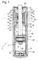
- FIG. 1shows a vibration damper 1, which has a cylinder 3, in which a piston rod 5 is mounted with a piston 7 axially movable.
- the piston 7divides the cylinder 3 in a piston rod remote and a piston rod side working space 9; 11, wherein a piston rod guide 13 the piston rod side working space 11 and a bottom valve 14 close the cylinder 3 end.
- the cylinder 3is enclosed by a container tube 15, whereby a compensation space 17 determined thereby compensates the volume of the retracting and extending piston rod 5.
- a valve sleeve 19is arranged, the bottom 21 rests indirectly via a throttle plate 23 at a facing in the direction of the working space 11 end face 25 of the piston rod guide 13.
- a valve ring 27is axially slidably mounted on the lateral surface of the piston rod 5, so that within the valve sleeve two working chambers 29; 31 present.
- the z. B.is formed by a longitudinal groove in the inner wall of the valve sleeve 13.
- the valve sleeve 19is guided radially from the inner wall of the cylinder 3, which is reduced in diameter at least in the region of the stroke of the valve ring, in this case over the entire length of the valve sleeve 19.
- the cylinder 3is designed in several parts in the axial direction and between the longitudinal sections 3a; 3b is an adapter ring 34 is arranged, the two longitudinal sections 3a; 3b centered to each other and ensures axial tension between the bottom valve 14 and the piston rod guide 13.
- An outer diameter reduction of the valve sleeve 19 in the form of at least one axial groove 35forms an axial passage between the piston rod side working chamber 11 and the present between the valve ring 27 and the bottom 21 working chamber 29 within the valve sleeve 19, wherein between the axial channel 35 and the working chamber 29 at least one Connecting channel 37 exists. You can also have multiple axial channels provide.
- the limited by a cover 39 of the valve sleeve 19 and the valve ring 27 working chamber 31has a throttle opening 41 to the piston rod side working space 11.
- the throttle opening 41is formed by at least one throttle disk 43 arranged between the cover and the valve sleeve.
- the valve ring 27has a friction ring 45 sliding on the piston rod and a sealing ring 47 enclosing the friction ring on the outside with a lateral surface, wherein the sealing ring 47 can move radially within limits of the friction ring 45.
- the friction ring 45can be axially supported on a bottom 49 of the sealing ring 47 and a retaining ring 51.
- a valve opening 53is executed in the cylinder, which via the Vorö Stammsectomy 23 and a connection channel 55 in the bottom 21 of the valve sleeve 19 to the working chambers 29; 31 of the valve sleeve 19 coupled to a Fluidenweg 56.
- the fluid pathis sealed to the compensation chamber 17 and is from an outer circumferential surface of the cylinder 3 a; 3b and at least on a longitudinal section enclosing cladding tube 58 is formed.
- Via a second connection opening 60 just above the bottom valve 14so that the two working spaces are interconnected.
- connection channel 55is formed by a passage opening 57 in the bottom, through which the piston rod 5 extends, wherein the valve ring 27 closes the passage opening 57 with its upper end face 59.
- damping mediumis displaced via the axial passage 35 between the valve sleeve 19 and the inner wall of the cylinder 3 in the valve sleeve 19.
- a smaller volume fractionflows through the cover 39 and the throttle opening 41 of the throttle disk 43 in the lower working chamber 31, wherein via the axial passage 33 between the working chambers 29; 31 is always a pressure equalization.
- the damping force generated in the piston rod extension movementis determined by the pre-opening disc 23 between the bottom 21 and the piston rod guide 13.
- the thereby displaced damping mediumflows through the Fluidenweg 56, the second port 60 and a check valve 62 in the piston rod remote working space 9.
- the check valve 62is formed by a radially elastic spring ring, which controls the second connection opening 60.
- valve ring 27comes to bear against the bottom 21 of the valve sleeve 19 on the inside and seals the connection channel 55 to the connection opening 53 and the connection channel 37.
- the axial passage 35 between the cylinder wall and the valve sleeveis closed by a seal 61 at the end, so that the damping medium located there can not continue to flow.
- the seal 61also serves to axially fix the valve sleeve 19 within the cylinder 3. From this Hublage the damping force of damping valves, z. B. in the piston 7, determined.
- the volume in the working chambers 29; 31 of the valve sleeve 19is compressed in the piston rod extension movement via the throttle opening 41, so that an additional hydraulic closing force acts on the valve ring 27.
- a piston rod-side displacer 65is moved into a stepped inner contour 67 of the adapter ring, wherein the displacer and the adapter ring form a hydraulic end stop.
- the Fig. 2shows a vibration damper 1 with a cylinder 3 at both ends passing through the piston rod 5, wherein in both working spaces 9; 11 each a valve sleeve 19; 19 'with a valve ring 27; 27 'is arranged.
- the entire vibration damper 1is a mirror image executable, provided that both valve sleeves 19; 19 'with an identical effective length executes to produce an identical amplitude-dependent damping force in both working directions of the piston rod 5. Due to the symmetrical structure, two adapter rings 14; 14 'for use.
- the cladding tube 58not only forms the fluid path 56, but also the compensation chamber 17, which is identical to the fluid path 56 and additionally has a variable-volume gas cushion 63, which is intended to compensate predominantly thermal volume changes of the damping medium.
- the components of the vibration damperwork after Fig. 2 identical to the execution after Fig. 1 , A deviation is that the function of the check valve 60; 62 each of the valve rings 27; 27 'is taken over. When a valve ring for one direction of movement opens, then the other valve ring closes the Fluidenweg 56 as soon as the valve ring rests against the bottom 21 of the valve sleeve.
- the Fig. 3 and 4show a vibration damper, which is based on the design Fig. 1 based. Deviating from Fig. 1 there is no pressure-controlled check valve 60; 62 for use, but a frictional force-controlled check valve 69, the valve body 71 is slidably mounted on the piston rod 5 and between two groove side surfaces 73; 75 of a valve groove 77 performs an axial operating movement, which is only dependent on the direction of movement of the piston rod 5, but not from the stroke.
- the check valve 69is the valve ring 27 which controls the connection channel 55 with the bottom 21, arranged in series downstream. Regardless of the position of the valve ring 27, only the discharge channel 57 is released when the Check valve 69 is open.
- the valve groove 77is formed by an end face of the piston rod guide 13 facing the piston rod side working space and an annular groove of the valve sleeve 19.
- valve body 71 of the check valve 69bears against the end face 73 of the piston rod and releases the connection channel 55.
- the valve body 71is moved by the frictional force of the piston rod 5 in the direction of the valve sleeve 19 and closes the connection channel 55.
- the damping mediumcan pass through the second connection opening 60 and the fluid path 56 to the first connection opening 53 and the closing movement by the pressure in the fluid path 56 support.
- the piston rod remote working space 9is separated from the piston rod side working chamber 11, so that the damping medium from the piston rod remote working space can not flow through the fluid path in the piston rod side working space, but escapes through the bottom valve 14 and the piston 7.
- the cylinder tubecan also be made in one piece with a reduced diameter length section. It is by no means necessary to provide a multi-part solution.
- a locking ring 79can be used for axial securing of the valve sleeve 19, by way of example.
- a transition 81 between the lengths of the cylinder of different diametermay, for. B. conical to achieve a low-stress forming zone.
- the design of the cylinderis independent of the design of the check valve 62; 69 to look at.
Landscapes
- Engineering & Computer Science (AREA)
- General Engineering & Computer Science (AREA)
- Mechanical Engineering (AREA)
- Fluid-Damping Devices (AREA)
Description
Translated fromGermanDie Erfindung betrifft einen Schwingungsdämpfer mit amplitudenabhängiger Dämpfkraft gemäß dem Oberbegriff von Patentanspruch 1.The invention relates to a vibration damper with amplitude-dependent damping force according to the preamble of
Aus der
Bei dem Schwingungsdämpfer nach der
Die Aufgabe der vorliegenden Erfindung besteht darin, einen Schwingungsdämpfer mit amplitudenabhängiger Dämpfkraft bereitzustellen, bei dem das aus dem Stand der Technik bekannte Bauraumproblem für die amplitudenabhängige Dämpfkraftverstellung behoben ist.The object of the present invention is to provide a vibration damper with amplitude-dependent damping force, in which the known from the prior art space problem for the amplitude-dependent damping force adjustment is corrected.
Erfindungsgemäß wird die Aufgabe dadurch gelöst, dass die Anschlussöffnung mit einem Fluidenweg gekoppelt ist, der beide Arbeitsräume über eine zweite Anschlussöffnung miteinander verbindet.According to the invention, the object is achieved in that the connection opening is coupled to a fluid path, which connects the two working spaces via a second connection opening.
Der große Vorteil besteht darin, dass der Ventilring nur noch eine einfache Schließfunktion für eine einzige Bewegungsrichtung ausführen muss. Dadurch kann der Ventilring axial deutlich kürzer gestaltet werden. Des Weiteren wird durch die Verbindung mit dem zweiten Arbeitsraum erreicht, dass insbesondere in den kolbenstangenseitigen Arbeitsraum kein Druckmedium aus einem Ausgleichsraum gelangen kann.The big advantage is that the valve ring only has to perform a simple closing function for a single direction of movement. As a result, the valve ring can be made axially much shorter. Furthermore, it is achieved by the connection with the second working space that in particular in the piston rod-side working space no pressure medium can pass from a compensation chamber.
In weiterer vorteilhafter Ausgestaltung wird der Fluidenweg von einem den Zylinder zumindest auf einem Längenabschnitt einschließenden Hüllrohr und der Außenmantelfläche des Zylinders gebildet. Es liegt ein in sich geschlossenes Aggregat vor.In a further advantageous embodiment, the fluid path is formed by a cladding tube enclosing the cylinder at least over a longitudinal section and the outer circumferential surface of the cylinder. There is a self-contained aggregate.
Des Weiteren ist vorgesehen, dass der Fluidenweg mit einem Rückschlagventil bestückt ist. Das Rückschlagventil bietet die Möglichkeit, dass die Strömungsrichtung im Fluidenweg so zu bestimmen, dass Dämpfventil im Kolben eine größere Dämpfkraft erzeugen können.Furthermore, it is provided that the fluid path is equipped with a check valve. The check valve offers the possibility of determining the direction of flow in the fluid path so that the damping valve in the piston can generate a greater damping force.
Dabei wird das Rückschlagventil vom Druck im kolbenstangenfernen Arbeitsraum in Schließrichtung vorgespannt.The check valve is biased by the pressure in the piston rod remote working space in the closing direction.
Gemäß einem vorteilhaften Unteranspruch wird das Rückschlagventil von einem radial elastischen Federring gebildet, der die Anschlussöffnung ansteuert.According to an advantageous embodiment, the check valve is formed by a radially elastic spring ring, which controls the connection opening.
Bei einer Alternativausführung wird das Rückschlagventil von einem auf der Kolbenstange axial verschiebbaren Ventilkörper gebildet wird.In an alternative embodiment, the check valve is formed by an axially displaceable on the piston rod valve body.
Dabei ist der Ventilkörper des Rückschlagventils in einer Nut einer Ventilhülse angeordnet, in der der Ventilring axial verschiebbar auf der Kolbenstange gelagert ist.In this case, the valve body of the check valve is arranged in a groove of a valve sleeve, in which the valve ring is mounted axially displaceably on the piston rod.
Letztlich liegen zwei Rückschlagventile vor. Der Ventilring bildet ein erstes Rückschlagventil und der Ventilkörper ein zweites Rückschlagventil, wobei die Rückschlagventile funktional in Reihe angeordnet sind und ein gegenläufiges Öffnungs/Schließverhalten aufweisen.Ultimately, there are two check valves. The valve ring forms a first check valve and the valve body a second check valve, wherein the check valves are operatively arranged in series and have an opposite opening / closing behavior.
Im Hinblick auf eine Standardisierung ist der Zylinder mindestes im Bereich des Hubweges des Ventilrings im Durchmesser verkleinert. Der Zylinderdurchmesser variiert zwischen den verschiedenen Anwendungsfällen, so dass die Bauelemente für jeden Zylinderdurchmesser angepasst werden müssten. Wenn man die Bauelemente für die amplitudenselektive Dämpfwirkung auf einen vergleichsweise kleinen Durchmesserbereich auslegt, dann können diese in verschiedenen Schwingungsdämpferbaugrößen verwendet werden.With a view to standardization, the cylinder is at least reduced in diameter in the region of the stroke of the valve ring. The cylinder diameter varies between the different use cases, so that the components for each cylinder diameter would have to be adjusted. By designing the components for the amplitude-selective damping action to a comparatively small diameter range, they can be used in various vibration damper sizes.
Bei einer ersten Variante ist der Zylinder einteilig und mit mindestens einem Übergang zwischen Längenabschnitten mit unterschiedlichen Durchmessern ausgeführt. Zu Sicherung der Ventilhülse im eingezogenen Bereich kann z. B. ein einfacher Sicherungsring dienen.In a first variant, the cylinder is made in one piece and with at least one transition between lengths of different diameters. To secure the valve sleeve in the retracted area can z. B. serve a simple circlip.
Alternativ ist vorgesehen, dass der Zylinder in Axialrichtung mehrteilig ausgeführt und zwischen den Längenabschnitten mit unterschiedlichem Durchmesser ein Adapterring angeordnet ist. Man kann z. B. standardmäßig einen Längenabschnitt für die Bauelemente betreffend die amplitudenselektive Dämpfkraft verwenden und diesen Längenabschnitt zusammen mit dem Adapterring wahlweise bei verschiedenen Schwingungsdämpferbaugrößen einsetzen.Alternatively, it is provided that the cylinder is designed in several parts in the axial direction and an adapter ring is arranged between the length sections with different diameters. You can z. B. by default use a length section for the components concerning the amplitude-selective damping force and use this length section together with the adapter ring optionally in different Schwingungsdämpferbaugrößen.
Des Weiteren besteht die Möglichkeit, dass der Adapterring eine gestufte Innenkontur zur Aufnahme eines kolbenstangenseitigen Verdrängers aufweist und damit einen hydraulischen Endanschlag bildet.Furthermore, there is the possibility that the adapter ring has a stepped inner contour for receiving a piston rod-side displacer and thus forms a hydraulic end stop.
Eine weitere Ausführungsform zeichnet sich dadurch aus, dass der Schwingungsdämpfer eine den Zylinder an beiden Enden durchsetzende Kolbenstange aufweist und in beiden Arbeitsräumen ein auf der Kolbenstange gleitender Ventilring angeordnet ist. Damit steht für beide Bewegungsrichtungen der Kolbenstange eine amplitudenselektive Dämpfkraft zur Verfügung. Man kann ebenfalls ein mehrteiliges Zylinderrohr verwenden, so dass ein symmetrischer Aufbau bezogen auf eine Querachse denkbar ist.A further embodiment is characterized in that the vibration damper has a piston rod passing through the cylinder at both ends and a valve ring which slides on the piston rod is arranged in both working spaces. This stands for both directions of movement of the Piston rod an amplitude-selective damping force available. You can also use a multi-part cylinder tube, so that a symmetrical structure based on a transverse axis is conceivable.
Anhand der folgenden Figurenbeschreibung soll die Erfindung näher erläutert werden.The invention will be explained in more detail with reference to the following description of the figures.
Es zeigt:
- Fig. 1
- Schwingungsdämpfer in Zweirohrausführung
- Fig. 2
- Schwingungsdämpfer mit durchgehender Kolbenstange
- Fig. 3 - 4
- Schwingungsdämpfer mit Rückschlagventil im kolbenstangenseitigen Arbeitsraum
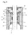
- Fig. 5
- Schwingungsdämpfer mit einem einteiligen Zylinder
- Fig. 1
- Vibration damper in two-tube design
- Fig. 2
- Vibration damper with continuous piston rod
- Fig. 3 - 4th
- Vibration damper with check valve in the piston rod side working space
- Fig. 5
- Vibration damper with a one-piece cylinder
Die
Der Zylinder 3 wird von einem Behälterrohr 15 umschlossen, wobei ein dadurch bestimmter Ausgleichsraum 17 das Volumen der ein- und ausfahrenden Kolbenstange 5 kompensiert.The
Im kolbenstangenseitigen Arbeitsraum 11 ist eine Ventilhülse 19 angeordnet, deren Boden 21 über eine Drosselscheibe 23 mittelbar an einer in Richtung des Arbeitsraums 11 weisenden Stirnfläche 25 der Kolbenstangenführung 13 anliegt. Innerhalb der Ventilhülse 19 ist ein Ventilring 27 auf der Mantelfläche der Kolbenstange 5 axial gleitend gelagert, so dass innerhalb der Ventilhülse zwei Arbeitskammern 29; 31 vorliegen. Zwischen den beiden Arbeitskammern 29; 31 besteht eine Strömungsverbindung 33, die z. B. von einer Längsnut in der Innenwandung der Ventilhülse 13 gebildet wird.In the piston rod-
Die Ventilhülse 19 wird radial von der Innenwandung des Zylinders 3 geführt, der mindestens im Bereich des Hubwegs des Ventilrings, in diesem Fall auf der Gesamtlänge der Ventilhülse 19 im Durchmesser verkleinert ist. Der Zylinder 3 ist in Axialrichtung mehrteilig ausgeführt und zwischen den Längenabschnitten 3a; 3b ist ein Adapterring 34 angeordnet, der die beiden Längenabschnitte 3a; 3b zueinander zentriert und eine axiale Verspannung zwischen dem Bodenventil 14 und der Kolbenstangenführung 13 gewährleistet. Eine Außendurchmesserreduzierung der Ventilhülse 19 in der Form mindestens einer Axialnut 35 bildet einen Axialkanal zwischen dem kolbenstangenseitigen Arbeitsraum 11 und der zwischen dem Ventilring 27 und dem Boden 21 vorliegenden Arbeitskammer 29 innerhalb der Ventilhülse 19, wobei zwischen dem Axialkanal 35 und der Arbeitskammer 29 noch mindestens ein Verbindungskanal 37 besteht. Man kann auch mehrere Axialkanäle vorsehen. Die von einem Deckel 39 der Ventilhülse 19 und dem Ventilring 27 begrenzte Arbeitskammer 31 weist eine Drosselöffnung 41 zum kolbenstangenseitigen Arbeitsraum 11 auf. Die Drosselöffnung 41 wird von mindestens einer zwischen dem Deckel und der Ventilhülse angeordneten Drosselscheibe 43 gebildet.The
Der Ventilring 27 verfügt über einen auf der Kolbenstange gleitenden Reibring 45 und einen den Reibring mit einer Mantelfläche außenseitig umschließenden Dichtring 47, wobei sich der Dichtring 47 radial in Grenzen zum Reibring 45 bewegen kann. Der Reibring 45 kann sich axial an einem Boden 49 des Dichtrings 47 und einem Sicherungsring 51 abstützen.The
In dieser Variante der Erfindung ist im Zylinder eine Ventilöffnung 53 ausgeführt, die über die Voröffnungsscheibe 23 und einen Anschlusskanal 55 im Boden 21 der Ventilhülse 19 an die Arbeitskammern 29; 31 der Ventilhülse 19 mit einem Fluidenweg 56 gekoppelt. Der Fluidenweg ist zum Ausgleichsraum 17 abgedichtet und wird von einer Außenmantelfläche des Zylinder 3a; 3b und einem zumindest auf einem Längenabschnitt umschließenden Hüllrohr 58 gebildet. Über eine zweite Anschlussöffnung 60 knapp oberhalb des Bodenventils 14 sind damit die beiden Arbeitsräume miteinander verbunden.In this variant of the invention, a
Der Anschlusskanal 55 wird von einer Durchgangsöffnung 57 im Boden gebildet, durch die auch die Kolbenstange 5 verläuft, wobei der Ventilring 27 die Durchgangsöffnung 57 mit seiner oberen Stirnfläche 59 verschließt.The
Bei einer Kolbenstangenbewegung in Ausfahrrichtung gleitet der Ventilring 27 innerhalb der Ventilhülse 19 aufgrund der Reibkraft zur Kolbenstange 5 synchron mit. Aus dem kolbenstangenseitigen Arbeitsraum 11 wird Dämpfmedium über den Axialkanal 35 zwischen der Ventilhülse 19 und der Innenwandung des Zylinders 3 in die Ventilhülse 19 verdrängt. Ein kleinerer Volumenanteil fließt über den Deckel 39 und die Drosselöffnung 41 der Drosselscheibe 43 in die untere Arbeitskammer 31, wobei über den Axialkanal 33 zwischen den Arbeitskammern 29; 31 stets ein Druckausgleich erfolgt. Die bei der Kolbenstangenausfahrbewegung erzeugte Dämpfkraft wird von der Voröffnungsscheibe 23 zwischen dem Boden 21 und der Kolbenstangenführung 13 bestimmt. Das dabei verdrängte Dämpfmedium fließt über den Fluidenweg 56, die zweite Anschlussöffnung 60 und einem Rückschlagventil 62 in den kolbenstangenfernen Arbeitsraum 9. Das Rückschlagventil 62 wird von einem radial elastischen Federring gebildet, der die zweite Anschlussöffnung 60 ansteuert.In a piston rod movement in the extension direction of the
Nach einer bestimmten Hublänge der Kolbenstangenführung kommt der Ventilring 27 innenseitig am Boden 21 der Ventilhülse 19 zur Anlage und dichtet den Anschlusskanal 55 zur Anschlussöffnung 53 und den Verbindungskanal 37 ab. Der Axialkanal 35 zwischen der Zylinderwandung und der Ventilhülse wird durch eine Dichtung 61 endseitig verschlossen, so dass das dort befindliche Dämpfmedium nicht weiterfließen kann. Zusätzlich dient die Dichtung 61 auch der axialen Fixierung der Ventilhülse 19 innerhalb des Zylinders 3. Ab dieser Hublage wird die Dämpfkraft von Dämpfventilen, z. B. im Kolben 7, bestimmt. Das Volumen in den Arbeitskammern 29; 31 der Ventilhülse 19 wird bei der Kolbenstangenausfahrbewegung über die Drosselöffnung 41 komprimiert, so dass eine zusätzliche hydraulische Schließkraft auf den Ventilring 27 wirkt.After a certain stroke length of the piston rod guide, the
Am Ende des Hubwegs der Kolbenstange 5 wird ein kolbenstangenseitiger Verdränger 65 in eine gestufte Innenkontur 67 des Adapterrings bewegt, wobei der Verdränger und der Adapterring einen hydraulischen Endanschlag bilden.At the end of the stroke of the
Bei einer Kolbenstangeneinfahrbewegung wird der Ventilring 19 aufgrund der Reibkraft zwischen dem Reibring und der Kolbenstange 5 von dem Boden 21 abgehoben und gibt den Anschlusskanal 55 wieder frei. Eine weitere Schließfunktion des Ventilrings 19 ist nicht notwendig. Gleichzeit wird das Dämpfmedium im kolbenstangenfernen Arbeitsraum 9 komprimiert, wodurch das Rückschlagventil 60 vom Druck in Schließrichtung vorgespannt wird, so dass keine Verbindung zum Fluidenweg 56 besteht. Das Dämpfmediumvolumen entsprechend dem verdrängten Volumen der Kolbenstange fließt durch das Bodenventil 14 in den Ausgleichsraum 17. Das restliche Dämpfmediumvolumen wird durch das Kolbenventil in den kolbenstangenseitigen Arbeitsraum verdrängt. Prinzipiell kann man auf das Rückschlagventil 60 verzichten, da das Kolbenstangenvolumen unabhängig davon durch das Bodenventil fließen muss, da der kolbenstangenseitige Arbeitsraum 11 nicht das gesamte Dämpfmediumvolumen des kolbenstangenfernen Arbeitsraums aufnehmen kann. Mit dem Rückschlagventil 60 wird das Dämpfmedium aus dem kolbenstangenfernen Arbeitsraum durch das Kolbenventil gezwungen, wodurch eine größere Dämpfkraft erzeugt wird, die man bei bestimmten Anwendungen erreichen will.In a piston rod retraction movement of the
Die
Die
Bei einer Kolbenstangenausfahrbewegung liegt der Ventilkörper 71 des Rückschlagventils 69 an der Stirnfläche 73 der Kolbenstange an und gibt den Anschlusskanal 55 frei. Sobald eine Kolbenstangeneinfahrbewegung vorliegt, wird der Ventilkörper 71 durch die Reibkraft der Kolbenstange 5 in Richtung der Ventilhülse 19 bewegt und verschließt den Anschlusskanal 55. Das Dämpfmedium kann durch die zweite Anschlussöffnung 60 und den Fluidenweg 56 zur ersten Anschlussöffnung 53 gelangen und die Schließbewegung durch den Druck im Fluidenweg 56 unterstützen. Danach ist der kolbenstangenferne Arbeitsraum 9 vom kolbenstangenseitigen Arbeitsraum 11 getrennt, so dass das Dämpfmedium aus dem kolbenstangenfernen Arbeitsraum nicht über den Fluidenweg in den kolbenstangenseitigen Arbeitsraum fließen kann, sondern über das Bodenventil 14 und den Kolben 7 entweicht.In a piston rod extension movement, the
Mit der
Claims (12)
- Vibration damper (1) with amplitude-dependent damping force, comprising a cylinder (3) which is filled with damping medium and in which a piston rod (5) having a piston (7) is arranged axially moveably, the piston (7) subdividing the cylinder (3) into a piston rod-side and a piston rod-remote working space (9; 11), with a valve ring (27) which is mounted on the piston rod (5) slidably under frictional force and which as a function of travel controls a connecting orifice (53) between the piston rod-side working space (9) of the vibration damper (1),characterized in that the connecting orifice (53) is coupled to a fluid path (56) which connects the two working spaces (9; 11) to one another via a second connecting orifice (60).
- Vibration damper according to Claim 1,characterized in that the fluid path (56) is formed by a casing tube (58) enclosing the cylinder (3), at least on a portion of length, and by the outer surface area of the cylinder (3).
- Vibration damper according to Claim 1,characterized in that the fluid path (56) is equipped with a non-return valve (62; 69).
- Vibration damper according to Claim 3,characterized in that the non-return valve (62; 69) is prestressed in the closing direction by the pressure in the piston rod-remote working space.
- Vibration damper according to Claim 4,characterized in that the non-return valve (62) is formed by a radially elastic spring ring which activates the connecting orifice (60).
- Vibration damper according to Claim 3,characterized in that the non-return valve (62) is formed by a valve body (71) displaceable axially on the piston rod (5).
- Vibration damper according to Claim 6,characterized in that the valve body (71) of the non-return valve (69) is arranged in a groove (77) of a valve sleeve (19) in which the valve ring (27) is mounted axially displaceably on the piston rod (5).
- Vibration damper according to Claim 1,characterized in that the cylinder (3) is reduced in diameter at least in the region of the stroke travel of the valve ring (27).
- Vibration damper according to Claim 8,characterized in that the cylinder (3) is formed in one part and with at least one transition (81) between portions of length having different diameters.
- Vibration damper according to Claim 8,characterized in that the cylinder (3) is of multi-part form in the axial direction, and an adapter ring (34) is arranged between the portions of length (3a; 3b) having different diameters.
- Vibration damper according to Claim 9,characterized in that the adapter ring (34) has a stepped inner contour (67) for receiving a piston rod-side displacer (65) and therefore forms a hydraulic limit stop.
- Vibration damper according to Claim 1,characterized in that the vibration damper (1) has a piston rod (5) passing through the cylinder (3) at both ends, and a valve ring (27; 27') sliding on the piston rod (5) is arranged in both working spaces (9; 11).
Applications Claiming Priority (1)
| Application Number | Priority Date | Filing Date | Title |
|---|---|---|---|
| DE200610054257DE102006054257A1 (en) | 2006-11-17 | 2006-11-17 | Vibration damper with amplitude-dependent damping force |
Publications (3)
| Publication Number | Publication Date |
|---|---|
| EP1923595A2 EP1923595A2 (en) | 2008-05-21 |
| EP1923595A3 EP1923595A3 (en) | 2010-12-15 |
| EP1923595B1true EP1923595B1 (en) | 2012-05-16 |
Family
ID=39092026
Family Applications (1)
| Application Number | Title | Priority Date | Filing Date |
|---|---|---|---|
| EP20070021522Not-in-forceEP1923595B1 (en) | 2006-11-17 | 2007-11-06 | Vibration damper with amplitude-dependent damping force |
Country Status (2)
| Country | Link |
|---|---|
| EP (1) | EP1923595B1 (en) |
| DE (1) | DE102006054257A1 (en) |
Cited By (1)
| Publication number | Priority date | Publication date | Assignee | Title |
|---|---|---|---|---|
| CN103851121A (en)* | 2012-12-07 | 2014-06-11 | 常州朗锐凯迩必减振技术有限公司 | Snaking prevention shock absorber |
Families Citing this family (6)
| Publication number | Priority date | Publication date | Assignee | Title |
|---|---|---|---|---|
| DE102008014543B3 (en)* | 2008-03-15 | 2009-06-25 | Zf Friedrichshafen Ag | Vibration damper with amplitude-selective damping force |
| DE102008040210A1 (en)* | 2008-07-07 | 2010-01-21 | Zf Friedrichshafen Ag | Vibration damper with a valve-controlled fluid connection |
| DE102008040643B3 (en) | 2008-07-23 | 2010-03-25 | Zf Friedrichshafen Ag | Vibration damper with amplitude-dependent damping force |
| DE102008042103A1 (en) | 2008-09-15 | 2010-03-25 | Zf Friedrichshafen Ag | Vibration damper with amplitude-selective damping force |
| CN114294368A (en)* | 2021-11-03 | 2022-04-08 | 浙江快乐树减震器有限公司 | Variable cavity structure for variable damping shock absorber |
| DE102023118621A1 (en) | 2023-07-13 | 2025-01-16 | Dr. Ing. H.C. F. Porsche Aktiengesellschaft | Vibration damper and motor vehicle with an active chassis |
Family Cites Families (8)
| Publication number | Priority date | Publication date | Assignee | Title |
|---|---|---|---|---|
| GB714180A (en)* | 1951-12-10 | 1954-08-25 | George Herbert Shepherd | Improvements in or relating to hydraulic dampers |
| DE3914298C1 (en)* | 1989-04-29 | 1990-08-30 | Boge Ag, 5208 Eitorf, De | Hydraulic oscillation damper with fluid ram - has axially slidable control disc, guided sealingly on piston rod in ram cylinder |
| US6352145B1 (en)* | 1998-10-07 | 2002-03-05 | Tenneco Automotive Inc. | Stroke dependent damping |
| DE19922838B4 (en)* | 1999-05-19 | 2004-11-04 | Zf Sachs Ag | vibration |
| DE19922839B4 (en)* | 1999-05-19 | 2004-05-13 | Zf Sachs Ag | vibration |
| US6926128B2 (en)* | 2003-06-10 | 2005-08-09 | Arvin Technologies, Inc. | Adaptive shock damping control |
| US7216747B2 (en)* | 2004-10-14 | 2007-05-15 | Tenneco Automotive Operating Company Inc. | Amplitude controlled orifice valving |
| US7431135B2 (en)* | 2004-10-27 | 2008-10-07 | Tenneco Automotive Operating Company Inc. | Stroke dependent damping |
- 2006
- 2006-11-17DEDE200610054257patent/DE102006054257A1/ennot_activeCeased
- 2007
- 2007-11-06EPEP20070021522patent/EP1923595B1/ennot_activeNot-in-force
Cited By (1)
| Publication number | Priority date | Publication date | Assignee | Title |
|---|---|---|---|---|
| CN103851121A (en)* | 2012-12-07 | 2014-06-11 | 常州朗锐凯迩必减振技术有限公司 | Snaking prevention shock absorber |
Also Published As
| Publication number | Publication date |
|---|---|
| EP1923595A2 (en) | 2008-05-21 |
| DE102006054257A1 (en) | 2008-05-29 |
| EP1923595A3 (en) | 2010-12-15 |
Similar Documents
| Publication | Publication Date | Title |
|---|---|---|
| EP1923595B1 (en) | Vibration damper with amplitude-dependent damping force | |
| DE2312445B2 (en) | Hydraulic shock absorber | |
| DE202006003197U1 (en) | Damper for furniture | |
| DE202009004752U1 (en) | Damper for furniture | |
| DE102014001192A1 (en) | Clamping device and component with such a clamping device | |
| EP3458739B1 (en) | Vibration damper having stroke-dependent damping force | |
| DE102008042103A1 (en) | Vibration damper with amplitude-selective damping force | |
| DE102005053394A1 (en) | Vibration damper with adjustable absorbing strength has fluid connection formed by the annular space between cylinder and pipe with a non-return valve arranged in the annular space | |
| EP2962022B1 (en) | Overflow valve | |
| DE1505497C3 (en) | ||
| DE102008040643B3 (en) | Vibration damper with amplitude-dependent damping force | |
| DE2165435C3 (en) | Shock absorbers for automobiles and rail vehicles | |
| DE3546236A1 (en) | Gas-filled spring with end-position damping | |
| DE102008042634B4 (en) | Vibration damper with amplitude-selective damping force | |
| DE102006047093A1 (en) | Vibration damper with amplitude-selective damping force | |
| DE2408055A1 (en) | Hydraulically operated length of height adjustable unit - where an inner cylinder acts as shut off and as actuator | |
| DE102005045267B3 (en) | Damper with adjustable damping force for damping vibrations has bypass channel hydraulically parallel to flow connection | |
| DE102008014543B3 (en) | Vibration damper with amplitude-selective damping force | |
| DE102010031144B4 (en) | Vibration damper with amplitude-dependent damping force | |
| EP1621780B1 (en) | Hydraulic cylinder with stroke end damping | |
| DE102008042637B4 (en) | Valve device with amplitude-dependent damping force | |
| EP1428962A1 (en) | Piston-cylinder unit | |
| LU103106B1 (en) | vibration damper for a motor vehicle | |
| DE3735210C1 (en) | Hydraulic steering damper | |
| EP1975478B1 (en) | Sealing element and corresponding sealing assembly |
Legal Events
| Date | Code | Title | Description |
|---|---|---|---|
| PUAI | Public reference made under article 153(3) epc to a published international application that has entered the european phase | Free format text:ORIGINAL CODE: 0009012 | |
| AK | Designated contracting states | Kind code of ref document:A2 Designated state(s):AT BE BG CH CY CZ DE DK EE ES FI FR GB GR HU IE IS IT LI LT LU LV MC MT NL PL PT RO SE SI SK TR | |
| AX | Request for extension of the european patent | Extension state:AL BA HR MK RS | |
| PUAL | Search report despatched | Free format text:ORIGINAL CODE: 0009013 | |
| AK | Designated contracting states | Kind code of ref document:A3 Designated state(s):AT BE BG CH CY CZ DE DK EE ES FI FR GB GR HU IE IS IT LI LT LU LV MC MT NL PL PT RO SE SI SK TR | |
| AX | Request for extension of the european patent | Extension state:AL BA HR MK RS | |
| 17P | Request for examination filed | Effective date:20110610 | |
| AKX | Designation fees paid | Designated state(s):AT BE BG CH CY CZ DE DK EE ES FI FR GB GR HU IE IS IT LI LT LU LV MC MT NL PL PT RO SE SI SK TR | |
| REG | Reference to a national code | Ref country code:DE Ref legal event code:R079 Ref document number:502007009855 Country of ref document:DE Free format text:PREVIOUS MAIN CLASS: F16F0009490000 Ipc:F16F0009200000 | |
| GRAP | Despatch of communication of intention to grant a patent | Free format text:ORIGINAL CODE: EPIDOSNIGR1 | |
| RIC1 | Information provided on ipc code assigned before grant | Ipc:F16F 9/20 20060101AFI20111123BHEP Ipc:F16F 9/49 20060101ALI20111123BHEP Ipc:F16F 9/50 20060101ALI20111123BHEP | |
| GRAS | Grant fee paid | Free format text:ORIGINAL CODE: EPIDOSNIGR3 | |
| GRAA | (expected) grant | Free format text:ORIGINAL CODE: 0009210 | |
| AK | Designated contracting states | Kind code of ref document:B1 Designated state(s):AT BE BG CH CY CZ DE DK EE ES FI FR GB GR HU IE IS IT LI LT LU LV MC MT NL PL PT RO SE SI SK TR | |
| REG | Reference to a national code | Ref country code:GB Ref legal event code:FG4D Free format text:NOT ENGLISH | |
| REG | Reference to a national code | Ref country code:CH Ref legal event code:EP | |
| REG | Reference to a national code | Ref country code:AT Ref legal event code:REF Ref document number:558254 Country of ref document:AT Kind code of ref document:T Effective date:20120615 | |
| REG | Reference to a national code | Ref country code:IE Ref legal event code:FG4D Free format text:LANGUAGE OF EP DOCUMENT: GERMAN | |
| REG | Reference to a national code | Ref country code:DE Ref legal event code:R096 Ref document number:502007009855 Country of ref document:DE Effective date:20120712 | |
| REG | Reference to a national code | Ref country code:NL Ref legal event code:VDEP Effective date:20120516 | |
| REG | Reference to a national code | Ref country code:LT Ref legal event code:MG4D Effective date:20120523 | |
| PG25 | Lapsed in a contracting state [announced via postgrant information from national office to epo] | Ref country code:FI Free format text:LAPSE BECAUSE OF FAILURE TO SUBMIT A TRANSLATION OF THE DESCRIPTION OR TO PAY THE FEE WITHIN THE PRESCRIBED TIME-LIMIT Effective date:20120516 Ref country code:CY Free format text:LAPSE BECAUSE OF FAILURE TO SUBMIT A TRANSLATION OF THE DESCRIPTION OR TO PAY THE FEE WITHIN THE PRESCRIBED TIME-LIMIT Effective date:20120516 Ref country code:PL Free format text:LAPSE BECAUSE OF FAILURE TO SUBMIT A TRANSLATION OF THE DESCRIPTION OR TO PAY THE FEE WITHIN THE PRESCRIBED TIME-LIMIT Effective date:20120516 Ref country code:IS Free format text:LAPSE BECAUSE OF FAILURE TO SUBMIT A TRANSLATION OF THE DESCRIPTION OR TO PAY THE FEE WITHIN THE PRESCRIBED TIME-LIMIT Effective date:20120916 Ref country code:LT Free format text:LAPSE BECAUSE OF FAILURE TO SUBMIT A TRANSLATION OF THE DESCRIPTION OR TO PAY THE FEE WITHIN THE PRESCRIBED TIME-LIMIT Effective date:20120516 Ref country code:SE Free format text:LAPSE BECAUSE OF FAILURE TO SUBMIT A TRANSLATION OF THE DESCRIPTION OR TO PAY THE FEE WITHIN THE PRESCRIBED TIME-LIMIT Effective date:20120516 | |
| PG25 | Lapsed in a contracting state [announced via postgrant information from national office to epo] | Ref country code:PT Free format text:LAPSE BECAUSE OF FAILURE TO SUBMIT A TRANSLATION OF THE DESCRIPTION OR TO PAY THE FEE WITHIN THE PRESCRIBED TIME-LIMIT Effective date:20120917 Ref country code:GR Free format text:LAPSE BECAUSE OF FAILURE TO SUBMIT A TRANSLATION OF THE DESCRIPTION OR TO PAY THE FEE WITHIN THE PRESCRIBED TIME-LIMIT Effective date:20120817 Ref country code:SI Free format text:LAPSE BECAUSE OF FAILURE TO SUBMIT A TRANSLATION OF THE DESCRIPTION OR TO PAY THE FEE WITHIN THE PRESCRIBED TIME-LIMIT Effective date:20120516 Ref country code:LV Free format text:LAPSE BECAUSE OF FAILURE TO SUBMIT A TRANSLATION OF THE DESCRIPTION OR TO PAY THE FEE WITHIN THE PRESCRIBED TIME-LIMIT Effective date:20120516 | |
| PG25 | Lapsed in a contracting state [announced via postgrant information from national office to epo] | Ref country code:CZ Free format text:LAPSE BECAUSE OF FAILURE TO SUBMIT A TRANSLATION OF THE DESCRIPTION OR TO PAY THE FEE WITHIN THE PRESCRIBED TIME-LIMIT Effective date:20120516 Ref country code:SK Free format text:LAPSE BECAUSE OF FAILURE TO SUBMIT A TRANSLATION OF THE DESCRIPTION OR TO PAY THE FEE WITHIN THE PRESCRIBED TIME-LIMIT Effective date:20120516 Ref country code:NL Free format text:LAPSE BECAUSE OF FAILURE TO SUBMIT A TRANSLATION OF THE DESCRIPTION OR TO PAY THE FEE WITHIN THE PRESCRIBED TIME-LIMIT Effective date:20120516 Ref country code:EE Free format text:LAPSE BECAUSE OF FAILURE TO SUBMIT A TRANSLATION OF THE DESCRIPTION OR TO PAY THE FEE WITHIN THE PRESCRIBED TIME-LIMIT Effective date:20120516 Ref country code:RO Free format text:LAPSE BECAUSE OF FAILURE TO SUBMIT A TRANSLATION OF THE DESCRIPTION OR TO PAY THE FEE WITHIN THE PRESCRIBED TIME-LIMIT Effective date:20120516 Ref country code:DK Free format text:LAPSE BECAUSE OF FAILURE TO SUBMIT A TRANSLATION OF THE DESCRIPTION OR TO PAY THE FEE WITHIN THE PRESCRIBED TIME-LIMIT Effective date:20120516 | |
| PG25 | Lapsed in a contracting state [announced via postgrant information from national office to epo] | Ref country code:IT Free format text:LAPSE BECAUSE OF FAILURE TO SUBMIT A TRANSLATION OF THE DESCRIPTION OR TO PAY THE FEE WITHIN THE PRESCRIBED TIME-LIMIT Effective date:20120516 | |
| PLBE | No opposition filed within time limit | Free format text:ORIGINAL CODE: 0009261 | |
| STAA | Information on the status of an ep patent application or granted ep patent | Free format text:STATUS: NO OPPOSITION FILED WITHIN TIME LIMIT | |
| 26N | No opposition filed | Effective date:20130219 | |
| PG25 | Lapsed in a contracting state [announced via postgrant information from national office to epo] | Ref country code:ES Free format text:LAPSE BECAUSE OF FAILURE TO SUBMIT A TRANSLATION OF THE DESCRIPTION OR TO PAY THE FEE WITHIN THE PRESCRIBED TIME-LIMIT Effective date:20120827 | |
| BERE | Be: lapsed | Owner name:ZF FRIEDRICHSHAFEN A.G. Effective date:20121130 | |
| REG | Reference to a national code | Ref country code:DE Ref legal event code:R097 Ref document number:502007009855 Country of ref document:DE Effective date:20130219 | |
| REG | Reference to a national code | Ref country code:CH Ref legal event code:PL | |
| GBPC | Gb: european patent ceased through non-payment of renewal fee | Effective date:20121106 | |
| PG25 | Lapsed in a contracting state [announced via postgrant information from national office to epo] | Ref country code:CH Free format text:LAPSE BECAUSE OF NON-PAYMENT OF DUE FEES Effective date:20121130 Ref country code:BG Free format text:LAPSE BECAUSE OF FAILURE TO SUBMIT A TRANSLATION OF THE DESCRIPTION OR TO PAY THE FEE WITHIN THE PRESCRIBED TIME-LIMIT Effective date:20120816 Ref country code:LI Free format text:LAPSE BECAUSE OF NON-PAYMENT OF DUE FEES Effective date:20121130 | |
| REG | Reference to a national code | Ref country code:IE Ref legal event code:MM4A | |
| PG25 | Lapsed in a contracting state [announced via postgrant information from national office to epo] | Ref country code:BE Free format text:LAPSE BECAUSE OF NON-PAYMENT OF DUE FEES Effective date:20121130 | |
| PG25 | Lapsed in a contracting state [announced via postgrant information from national office to epo] | Ref country code:IE Free format text:LAPSE BECAUSE OF NON-PAYMENT OF DUE FEES Effective date:20121106 | |
| PG25 | Lapsed in a contracting state [announced via postgrant information from national office to epo] | Ref country code:GB Free format text:LAPSE BECAUSE OF NON-PAYMENT OF DUE FEES Effective date:20121106 Ref country code:MT Free format text:LAPSE BECAUSE OF FAILURE TO SUBMIT A TRANSLATION OF THE DESCRIPTION OR TO PAY THE FEE WITHIN THE PRESCRIBED TIME-LIMIT Effective date:20120516 | |
| REG | Reference to a national code | Ref country code:AT Ref legal event code:MM01 Ref document number:558254 Country of ref document:AT Kind code of ref document:T Effective date:20121130 | |
| PG25 | Lapsed in a contracting state [announced via postgrant information from national office to epo] | Ref country code:AT Free format text:LAPSE BECAUSE OF NON-PAYMENT OF DUE FEES Effective date:20121130 | |
| PGFP | Annual fee paid to national office [announced via postgrant information from national office to epo] | Ref country code:FR Payment date:20131108 Year of fee payment:7 | |
| PG25 | Lapsed in a contracting state [announced via postgrant information from national office to epo] | Ref country code:TR Free format text:LAPSE BECAUSE OF FAILURE TO SUBMIT A TRANSLATION OF THE DESCRIPTION OR TO PAY THE FEE WITHIN THE PRESCRIBED TIME-LIMIT Effective date:20120516 Ref country code:MC Free format text:LAPSE BECAUSE OF NON-PAYMENT OF DUE FEES Effective date:20121130 | |
| PG25 | Lapsed in a contracting state [announced via postgrant information from national office to epo] | Ref country code:LU Free format text:LAPSE BECAUSE OF NON-PAYMENT OF DUE FEES Effective date:20121106 | |
| PG25 | Lapsed in a contracting state [announced via postgrant information from national office to epo] | Ref country code:HU Free format text:LAPSE BECAUSE OF FAILURE TO SUBMIT A TRANSLATION OF THE DESCRIPTION OR TO PAY THE FEE WITHIN THE PRESCRIBED TIME-LIMIT Effective date:20071106 | |
| REG | Reference to a national code | Ref country code:FR Ref legal event code:ST Effective date:20150731 | |
| PG25 | Lapsed in a contracting state [announced via postgrant information from national office to epo] | Ref country code:FR Free format text:LAPSE BECAUSE OF NON-PAYMENT OF DUE FEES Effective date:20141201 | |
| PGFP | Annual fee paid to national office [announced via postgrant information from national office to epo] | Ref country code:DE Payment date:20151103 Year of fee payment:9 | |
| REG | Reference to a national code | Ref country code:DE Ref legal event code:R119 Ref document number:502007009855 Country of ref document:DE | |
| PG25 | Lapsed in a contracting state [announced via postgrant information from national office to epo] | Ref country code:DE Free format text:LAPSE BECAUSE OF NON-PAYMENT OF DUE FEES Effective date:20170601 |