EP1922824B1 - A wireless communication device using adaptive beamforming - Google Patents
A wireless communication device using adaptive beamformingDownload PDFInfo
- Publication number
- EP1922824B1 EP1922824B1EP06801212.9AEP06801212AEP1922824B1EP 1922824 B1EP1922824 B1EP 1922824B1EP 06801212 AEP06801212 AEP 06801212AEP 1922824 B1EP1922824 B1EP 1922824B1
- Authority
- EP
- European Patent Office
- Prior art keywords
- processor
- transmitter device
- information
- phased array
- antenna
- Prior art date
- Legal status (The legal status is an assumption and is not a legal conclusion. Google has not performed a legal analysis and makes no representation as to the accuracy of the status listed.)
- Active
Links
- 238000004891communicationMethods0.000titleclaimsdescription60
- 230000003044adaptive effectEffects0.000titleclaimsdescription17
- 230000005540biological transmissionEffects0.000claimsdescription18
- 230000004044responseEffects0.000claimsdescription3
- 238000012546transferMethods0.000description25
- 238000000034methodMethods0.000description11
- 238000012545processingMethods0.000description7
- 238000012549trainingMethods0.000description7
- 238000010586diagramMethods0.000description6
- 239000013598vectorSubstances0.000description6
- 239000011159matrix materialSubstances0.000description5
- 230000015654memoryEffects0.000description5
- 230000008569processEffects0.000description5
- 230000003287optical effectEffects0.000description4
- 235000019800disodium phosphateNutrition0.000description3
- 230000002093peripheral effectEffects0.000description3
- 230000008859changeEffects0.000description2
- 238000012512characterization methodMethods0.000description2
- 238000004590computer programMethods0.000description2
- 230000006870functionEffects0.000description2
- 235000010627Phaseolus vulgarisNutrition0.000description1
- 244000046052Phaseolus vulgarisSpecies0.000description1
- 230000009471actionEffects0.000description1
- 230000004075alterationEffects0.000description1
- 230000009286beneficial effectEffects0.000description1
- 230000001413cellular effectEffects0.000description1
- 239000002131composite materialSubstances0.000description1
- 238000005516engineering processMethods0.000description1
- 230000003203everyday effectEffects0.000description1
- 239000002360explosiveSubstances0.000description1
- 230000007274generation of a signal involved in cell-cell signalingEffects0.000description1
- 230000002452interceptive effectEffects0.000description1
- 238000005259measurementMethods0.000description1
- 230000007246mechanismEffects0.000description1
- 238000012986modificationMethods0.000description1
- 230000004048modificationEffects0.000description1
- 230000000644propagated effectEffects0.000description1
- 230000005236sound signalEffects0.000description1
- 238000001228spectrumMethods0.000description1
- 238000003756stirringMethods0.000description1
- 239000000126substanceSubstances0.000description1
- 230000000007visual effectEffects0.000description1
Images


Classifications
- H—ELECTRICITY
- H04—ELECTRIC COMMUNICATION TECHNIQUE
- H04B—TRANSMISSION
- H04B7/00—Radio transmission systems, i.e. using radiation field
- H04B7/02—Diversity systems; Multi-antenna system, i.e. transmission or reception using multiple antennas
- H04B7/04—Diversity systems; Multi-antenna system, i.e. transmission or reception using multiple antennas using two or more spaced independent antennas
- H04B7/06—Diversity systems; Multi-antenna system, i.e. transmission or reception using multiple antennas using two or more spaced independent antennas at the transmitting station
- H04B7/0613—Diversity systems; Multi-antenna system, i.e. transmission or reception using multiple antennas using two or more spaced independent antennas at the transmitting station using simultaneous transmission
- H04B7/0615—Diversity systems; Multi-antenna system, i.e. transmission or reception using multiple antennas using two or more spaced independent antennas at the transmitting station using simultaneous transmission of weighted versions of same signal
- H—ELECTRICITY
- H04—ELECTRIC COMMUNICATION TECHNIQUE
- H04M—TELEPHONIC COMMUNICATION
- H04M1/00—Substation equipment, e.g. for use by subscribers
- H—ELECTRICITY
- H04—ELECTRIC COMMUNICATION TECHNIQUE
- H04B—TRANSMISSION
- H04B7/00—Radio transmission systems, i.e. using radiation field
- H04B7/02—Diversity systems; Multi-antenna system, i.e. transmission or reception using multiple antennas
- H04B7/04—Diversity systems; Multi-antenna system, i.e. transmission or reception using multiple antennas using two or more spaced independent antennas
- H04B7/06—Diversity systems; Multi-antenna system, i.e. transmission or reception using multiple antennas using two or more spaced independent antennas at the transmitting station
- H04B7/0613—Diversity systems; Multi-antenna system, i.e. transmission or reception using multiple antennas using two or more spaced independent antennas at the transmitting station using simultaneous transmission
- H04B7/0615—Diversity systems; Multi-antenna system, i.e. transmission or reception using multiple antennas using two or more spaced independent antennas at the transmitting station using simultaneous transmission of weighted versions of same signal
- H04B7/0617—Diversity systems; Multi-antenna system, i.e. transmission or reception using multiple antennas using two or more spaced independent antennas at the transmitting station using simultaneous transmission of weighted versions of same signal for beam forming
- H—ELECTRICITY
- H04—ELECTRIC COMMUNICATION TECHNIQUE
- H04B—TRANSMISSION
- H04B7/00—Radio transmission systems, i.e. using radiation field
- H04B7/02—Diversity systems; Multi-antenna system, i.e. transmission or reception using multiple antennas
- H04B7/04—Diversity systems; Multi-antenna system, i.e. transmission or reception using multiple antennas using two or more spaced independent antennas
- H04B7/06—Diversity systems; Multi-antenna system, i.e. transmission or reception using multiple antennas using two or more spaced independent antennas at the transmitting station
- H04B7/0613—Diversity systems; Multi-antenna system, i.e. transmission or reception using multiple antennas using two or more spaced independent antennas at the transmitting station using simultaneous transmission
- H04B7/0615—Diversity systems; Multi-antenna system, i.e. transmission or reception using multiple antennas using two or more spaced independent antennas at the transmitting station using simultaneous transmission of weighted versions of same signal
- H04B7/0619—Diversity systems; Multi-antenna system, i.e. transmission or reception using multiple antennas using two or more spaced independent antennas at the transmitting station using simultaneous transmission of weighted versions of same signal using feedback from receiving side
Definitions
- the present inventionrelates to the field of wireless communication; more particularly, the present invention relates to a wireless communication device that uses adaptive beamforming.
- DDWGDigital Display Working Group
- DVIDigital Visual Interface
- HDCPhigh definition video codec
- DTCPdigital video monitor interfaces
- HDMIis a connection standard that combines DVI and HDCP.
- HDMIwas developed to meet the explosive demand for high-definition audio and video.
- Both DVI and HDMIhave two key advantages. First, both integrate all video and sound signals onto a single, thin cable, thereby substantially simplifying the connection of components. Second, the content sent over the cable remains in its original, uncompressed digital format.
- HDCPis a system for protecting content being transferred over DVI and HDMI from being copied. See HDCP 1.0.
- HDCPprovides authentication, encryption, and revocation. Specialized circuitry in the playback device and in the display monitor encrypts video data before it is sent over. With HDCP, content is encrypted immediately before (or inside) the DVI or HDMI transmitter chip and decrypted immediately after (or inside) the DVI or HDMI receiver chip.
- HDCPimplements authentication to verify that the receiving device (e.g., a display, a television, etc.) is licensed to receive encrypted content. Re-authentication occurs approximately every two seconds to continuously confirm the security of the DVI or HDMI interface. If, at any time, re-authentication does not occur, for example by disconnecting a device and/or connecting an illegal recording device, the source device (e.g., a DVD player, a set-top box, etc.) ends transmission of encrypted content.
- the receiving devicee.g., a display, a television, etc.
- Re-authenticationoccurs approximately every two seconds to continuously confirm the security of the DVI or HDMI interface. If, at any time, re-authentication does not occur, for example by disconnecting a device and/or connecting an illegal recording device, the source device (e.g., a DVD player, a set-top box, etc.) ends transmission of encrypted content.
- EP 1447925(Samsung Electronics Co. Ltd) describes a wireless communications system in which transmission capacity is maximised using multiple antennae.
- the systemincludes a base station which applies predetermined weight vectors to multi-user signals and transmits the multi-user signals through a plurality of transmission antennae, and a plurality of mobile stations which receive and process the multi-user signals.
- Each mobile stationincludes a signal reception unit which processes the multi-user signals, and a feedback signal generation unit which estimates channel characteristics, over which the multi-user signals have been transmitted, from the multi-user signals, classifies a plurality of weight vectors to be applied to the estimated channel characteristics into a plurality of sets such that vectors orthogonal to one another are classified into a single set, selects a set maximising a transmission capacity from among the classified sets, and feeds back weight indexes of weight vectors included in the selected set and weighted channel information to the base station.
- EP 1175022(Samsung Electronics Co. Ltd) concerns what is referred to as a "transmission antenna diversity method".
- Channel informationis measured from signals received from a plurality of antennae in a base station and a channel information matrix is output.
- the channel information matrixis transformed according to a transform matrix composed of a complex basis vector set.
- Reception power with respect to the plurality of antennaeis calculated based on the transformed channel information matrix. Power is equally distributed to transmitting antennae.
- US 2003/0161410 A1discloses a MIMO device with directional antenna beamforming and feedback channels for compensating performance of transmit MIMO antennas.
- a transmitter deviceaccording to claim 1 is provided.
- a receiver deviceaccording to claim 22 is provided.
- peripheralcomprising:
- the wireless communicationoccurs using a wireless transceiver with an adaptive beamforming antenna.
- the wireless communicationcould occur with a wireless receiver or transmitter.
- the wireless communicationincludes an additional link, or channel, for transmitting information between a transmitter and a receiver.
- the linkmay be uni-directional or bi-directional.
- the channelis used to send antenna information back from a receiver to a transmitter to enable the transmitter to adapt its antenna array by steering the antenna elements to find a path to another direction. This may be obstacle avoidance.
- the linkis also used to transfer information corresponding to the content that is being transferred wirelessly (e.g., wireless video). This information may be content protection information.
- the linkis used to transfer encryption keys and acknowledgements of encryption keys when the transceivers are transferring HDMI data.
- the linktransfers control information and content protection information.
- This additional linkmay be a separate channel in the 60 GHz band.
- the linkmay be a wireless channel in the 2.4 GHz band.
- the present inventionalso relates to an apparatus for performing the operations herein.
- This apparatusmay be specially constructed for the required purposes, or it may comprise a general purpose computer selectively activated or reconfigured by a computer program stored in the computer.
- a computer programmay be stored in a computer readable storage medium, such as, but is not limited to, any type of disk including floppy disks, optical disks, CD-ROMs, and magnetic-optical disks, read-only memories (ROMs), random access memories (RAMs), EPROMs, EEPROMs, magnetic or optical cards, or any type of media suitable for storing electronic instructions, and each coupled to a computer system bus.
- a machine-readable mediumincludes any mechanism for storing or transmitting information in a form readable by a machine (e.g., a computer).
- a machine-readable mediumincludes read only memory ("ROM”); random access memory (“RAM”); magnetic disk storage media; optical storage media; flash memory devices; electrical, optical, acoustical or other form of propagated signals (e.g., carrier waves, infrared signals, digital signals, etc.); etc.
- FIG. 1is a block diagram of one embodiment of a communication system.
- the systemcomprises media receiver 100, a media receiver interface 102, a transmitting device 140, a receiving device 141, a media player interface 113, a media player 114 and a display 115.
- Media receiver 100receives content from a source (not shown).
- media receiver 100comprises a set top box.
- the contentmay comprise baseband digital video, such as, for example, but not limited to, content adhering to the HDMI or DVI standards.
- media receiver 100may include a transmitter (e.g., an HDMI transmitter) to forward the received content.
- Media receiver 100sends content 101 to transmitter device 140 via media receiver interface 102.
- media receiver interface 102includes logic that converts content 101 into HDMI content.
- media receiver interface 102may comprise an HDMI plug and content 101 is sent via a wired connection; however, the transfer could occur through a wireless connection.
- content 101comprises DVI content.
- the transfer of content 101 between media receiver interface 102 and transmitter device 140occurs over a wired connection; however, the transfer could occur through a wireless connection.
- Transmitter device 140wirelessly transfers information to receiver device 141 using two wireless connections.
- One of the wireless connectionsis through a phased array antenna with adaptive beamforming.
- the other wireless connectionis via wireless communications channel 107, referred to herein as the back channel.
- wireless communications channel 107is uni-directional. In an alternative embodiment, wireless communications channel 107 is bi-directional.
- Receiver device 141transfers the content received from transmitter device 140 to media player 114 via media player interface 113.
- the transfer of the content between receiver device 141 and media player interface 113occurs through a wired connection; however, the transfer could occur through a wireless connection.
- media player interface 113comprises an HDMI plug.
- the transfer of the content between media player interface 113 and media player 114occurs through a wired connection; however, the transfer could occur through a wireless connection.
- Media player 114causes the content to be played on display 115.
- the contentis HDMI content and media player 114 transfer the media content to display via a wired connection; however, the transfer could occur through a wireless connection.
- Display 115may comprise a plasma display, an LCD, a CRT, etc.
- system in Figure 1may be altered to include a DVD player/recorder in place of a DVD player/recorder to receive, and play and/or record the content.
- transmitter 140 and media receiver interface 102are part of media receiver 100.
- receiver 140, media player interface 113, and media player 114are all part of the same device.
- receiver 140, media player interface 113, media player 114, and display 115are all part of the display. An example of such a device is shown in Figure 3 .
- transmitter device 140comprises a processor 103, an optional baseband processing component 104, a phased array antenna 105, and a wireless communication channel interface 106.
- Phased array antenna 105comprises a radio frequency (RF) transmitter having a digitally controlled phased array antenna coupled to and controlled by processor 103 to transmit content to receiver device 141 using adaptive beamforming.
- RFradio frequency
- receiver device 141comprises a processor 112, an optional baseband processing component 111, a phased array antenna 110, and a wireless communication channel interface 109.
- Phased array antenna 110comprises a radio frequency (RF) transmitter having a digitally controlled phased array antenna coupled to and controlled by processor 112 to receive content from transmitter device 140 using adaptive beamforming.
- RFradio frequency
- processor 103generates baseband signals that are processed by baseband signal processing 104 prior to being wirelessly transmitted by phased array antenna 105.
- receiver device 141includes baseband signal processing to convert analog signals received by phased array antenna 110 into baseband signals for processing by processor 112.
- the baseband signalsare orthogonal frequency division multiplex (OFDM) signals.
- transmitter device 140 and/or receiver device 141are part of separate transceivers.
- Transmitter device 140 and receiver device 141perform wireless communication using phased array antenna with adaptive beamforming that allows beam steering. Beamforming is well known in the art.
- processor 103sends digital control information to phased array antenna 105 to indicate an amount to shift one or more phase shifters in phased array antenna 105 to steer a beam formed thereby in a manner well-known in the art.
- Processor 112uses digital control information as well to control phased array antenna 110. The digital control information is sent using control channel 121 in transmitter device 140 and control channel 122 in receiver device 141.
- the digital control informationcomprises a set of coefficients.
- each of processors 103 and 112comprises a digital signal processor.
- Wireless communication link interface 106is coupled to processor 103 and provides an interface between wireless communication link 107 and processor 103 to communicate antenna information relating to the use of the phased array antenna and to communicate information to facilitate playing the content at another location.
- the information transferred between transmitter device 140 and receiver device 141 to facilitate playing the contentincludes encryption keys sent from processor 103 to processor 112 of receiver device 141 and one or more acknowledgments from processor 112 of receiver device 141 to processor 103 of transmitter device 140.
- Wireless communication link 107also transfers antenna information between transmitter device 140 and receiver device 141. During initialization of the phased array antennas 105 and 110, wireless communication link 107 transfers information to enable processor 103 to select a direction for the phased array antenna 105.
- the informationincludes, but is not limited to, antenna location information and performance information corresponding to the antenna location, such as one or more pairs of data that include the position of phased array antenna 110 and the signal strength of the channel for that antenna position.
- the informationincludes, but is not limited to, information sent by processor 112 to processor 103 to enable processor 103 to determine which portions of phased array antenna 105 to use to transfer content.
- wireless communication link 107transfers an indication of the status of communication path from the processor 112 of receiver device 141.
- the indication of the status of communicationcomprises an indication from processor 112 that prompts processor 103 to steer the beam in another direction (e.g., to another channel). Such prompting may occur in response to interference with transmission of portions of the content.
- the informationmay specify one or more alternative channels that processor 103 may use.
- the antenna informationcomprises information sent by processor 112 to specify a location to which receiver device 141 is to direct phased array antenna 110. This may be useful during initialization when transmitter device 140 is telling receiver device 141 where to position its antenna so that signal quality measurements can be made to identify the best channels.
- the position specifiedmay be an exact location or may be a relative location such as, for example, the next location in a predetermined location order being followed by transmitter device 140 and receiver device 141.
- wireless communications link 107transfers information from receiver device 141 to transmitter device 140 specifying antenna characteristics of phased array antenna 110, or vice versa.
- FIG 2is a block diagram of one embodiment of an adaptive beam forming multiple antenna radio system containing transmitter device 140 and receiver device 141 of Figure 1 .
- Transceiver 200includes multiple independent transmit and receive chains.
- Transceiver 200performs phased array beam forming using a phased array that takes an identical RF signal and shifts the phase for one or more antenna elements in the array to achieve beam steering.
- DSPDigital Signal Processor 201 formats the content and generates real time baseband signals.
- DSP 201may provide modulation, FEC coding, packet assembly, interleaving and automatic gain control.
- DSP 201then forwards the baseband signals to be modulated and sent out on the RF portion of the transmitter.
- the contentis modulated into OFDM signals in a manner well known in the art.
- Digital-to-analog converter (DAC) 202receives the digital signals output from DSP 201 and converts them to analog signals.
- the signals output from DAC 202are between 0-256 MHz signals.
- Mixer 203receives signals output from DAC 202 and combines them with a signal from a local oscillator (LO) 204.
- the signals output from mixer 203are at an intermediate frequency.
- the intermediate frequencyis between 2-9 GHz.
- phase shifters 205 0-Nreceive the output from mixer 203.
- a demultiplieris included to control which phase shifters receive the signals.
- these phase shiftersare quantized phase shifters.
- the phase shiftersmay be replaced by complex multipliers.
- DSP 201also controls, via control channel 208, the phase and magnitude of the currents in each of the antenna elements in phased array antenna 220 to produce a desired beam pattern in a manner well-known in the art. In other words, DSP 201 controls the phase shifters 205 0-N of phased array antenna 220 to produce the desired pattern.
- phase shifters 205 0-Nproduce an output that is sent to one of power amplifiers 206 0-N , which amplify the signal.
- the amplified signalsare sent to antenna array 207 which has multiple antenna elements 207 0-N -
- the signals transmitted from antennas 207 0-Nare radio frequency signals between 56-64 GHz.
- multiple beamsare output from phased array antenna 220.
- phase shifters 211 0-Nreceive the wireless transmissions from antennas 207 0-N and provide them to phase shifters 211 0-N .
- phase shifters 211 0-Ncomprise quantitized phase shifters.
- phase shifters 211 0-Nmay be replaced by complex multipliers.
- Phase shifters 211 0-Nreceive the signals from antennas 210 0-N , which are combined to form a single line feed output.
- a multiplexeris used to combine the signals from the different elements and output the single feed line.
- the output of phase shifters 211 0-Nis input to intermediate frequency (IF) amplifier 212, which reduces the frequency of the signal to an intermediate frequency.
- the intermediate frequencyis between 2-9 GHz.
- Mixer 213receives the output of the IF amplifier 212 and combines it with a signal from LO 214 in a manner well-known in the art.
- the output of mixer 213is a signal in the range of 0-250 MHz.
- Analog-to-digital converter (ADC) 215receives the output of mixer 213 and converts it to digital form.
- the digital output from ADC 215is received by DSP 216.
- DSP 216restores the amplitude and phase of the signal.
- DSPs 211may provide demodulation, packet disassembly, de-interleaving and automatic gain control.
- each of the transceiversincludes a controlling microprocessor that sets up control information for DSP.
- the controlling microprocessormay be on the same die as the DSP.
- the DSPsimplement an adaptive algorithm with the beam forming weights being implemented in hardware. That is, the transmitter and receiver work together to perform the beam forming in RF frequency using digitally controlled analog phase shifters; however, in an alternative embodiment, the beamforming is performed in IF.
- Phase shifters 205 0-N and 211 0-Nare controlled via control channel 208 and control channel 217, respectfully, via their respective DSPs in a manner well known in the art.
- DSP 201controls phase shifters 105 0-N to have the transmitter perform adaptive beamforming to steer the beam while DSP 211 controls phase shifters 211 0-N to direct antenna elements to receive the wireless transmission from antenna elements and combine the signals from different elements to form a single line feed output.
- a multiplexeris used to combine the signals from the different elements and output the single feed line.
- DSP 201performs the beam steering by pulsing, or energizing, the appropriate phase shifter connected to each antenna element.
- the pulsing algorithm under DSP 201controls the phase and gain of each element.
- Performing DSP controlled phase array beamformingis well known in the art.
- the adaptive beam forming antennais used to avoid interfering obstructions. By adapting the beam forming and steering the beam, the communication can occur avoiding obstructions which may prevent or interfere with the wireless transmissions between the transmitter and the receiver.
- the adaptive beamforming antennashave three phases of operations.
- the three phases of operationsare the training phase, a searching phase, and a tracking phase.
- the training phase and searching phaseoccur during initialization.
- the training phasedetermines the channel profile with predetermined sequences of spatial patterns ⁇ A î ⁇ and ⁇ B ⁇ ⁇ .
- the searching phasecomputes a list of candidate spatial patterns ⁇ A î ⁇ , ⁇ B ⁇ ⁇ and selects a prime candidate ⁇ A 0 ⁇ , B 0 ⁇ ⁇ for use in the data transmission between the transmitter of one transceiver and the receiver of another.
- the tracking phasekeeps track of the strength of the candidate list. When the prime candidate is obstructed, the next pair of spatial patterns is selected for use.
- the transmittersends out a sequence of spatial patterns ⁇ A î ⁇ .
- the receiverprojects the received signal onto another sequence of patterns ⁇ B ⁇ ⁇ .
- a channel profileis obtained over the pair ⁇ A î ⁇ , ⁇ B ⁇ ⁇ .
- an exhaustive trainingis performed between the transmitter and the receiver in which the antenna of the receiver is positioned at all locations and the transmitter sending multiple spatial patterns.
- Exhaustive trainingis well-known in the art.
- M transmit spatial patternsare transmitted by the transmitter and N received spatial patterns are received by the receiver to form an N by M channel matrix.
- the transmittergoes through a pattern of transmit sectors and the receiver searches to find the strongest signal for that transmission. Then the transmitter moves to the next sector.
- a ranking of all the positions of the transmitter and the receiver and the signals strengths of the channel at those positionshas been obtained.
- the informationis maintained as pairs of positions of where the antennas are pointed and signal strengths of the channels.
- the listmay be used to steer the antenna beam in case of interference.
- bi-section trainingis used in which the space is divided in successively narrow sections with orthogonal antenna patterns being sent to obtain a channel profile.
- the DSP 101Assuming DSP 101 is in a stable state and the direction the antenna should point is already determined. In the nominal state, the DSP will have a set of coefficients that it sends the phase shifters. The coefficients indicate the amount of phase the phase shifter is to shift the signal for its corresponding antennas. For example, DSP 101 sends a set digital control information to the phase shifters that indicate the different phase shifters are to shift different amounts, e.g., shift 30 degrees, shift 45 degrees, shift 90 degrees, shift 180 degrees, etc. Thus, the signal that goes to that antenna element will be shifted by a certain number of degrees of phase.
- the end result of shifting, for example, 16, 34, 32, 64 elements in the array by different amountsenables the antenna to be steered in a direction that provides the most sensitive reception location for the receiving antenna. That is, the composite set of shifts over the entire antenna array provides the ability to stir where the most sensitive point of the antenna is pointing over the hemisphere.
- the appropriate connection between the transmitter and the receivermay not be a direct path from the transmitter to the receiver.
- the most appropriate pathmay be to bounce off the ceiling.
- the wireless communication systemincludes a back channel, or link, for transmitting information between wireless communication devices (e.g., a transmitter and receiver, a pair of transceivers, etc.).
- the informationis related to the beamforming antennas and enables one or both of the wireless communication devices to adapt the array of antenna elements to better direct the antenna elements of a transmitter to the antenna elements of the receiving device together.
- the informationalso includes information to facilitate the use of the content being wirelessly transferred between the antenna elements of the transmitter and the receiver.
- back channel 220is coupled between DSP 216 and DSP 201 to enable DSP 216 to send tracking and control information to DSP 201.
- back channel 220functions as a high speed downlink and an acknowledgement channel.
- the back channelis also used to transfer information corresponding to the application for which the wireless communication is occurring (e.g., wireless video). Such information includes content protection information.
- the back channelis used to transfer encryption information (e.g., encryption keys and acknowledgements of encryption keys) when the transceivers are transferring HDMI data. In such a case, the back channel is used for content protection communications.
- encryptionis used to validate that the data sink is a permitted device (e.g., a permitted display).
- a permitted devicee.g., a permitted display
- Blocks of frames for the HD TV dataare encrypted with different keys and then those keys have to be acknowledged back on back channel 220 in order to validate the player.
- Back channel 220transfers the encryption keys in the forward direction to the receiver and acknowledgements of key receipts from the receiver in the return direction.
- encrypted informationis sent in both directions.
- the use of the back channel for content protection communicationsis beneficial because it avoids having to complete a lengthy retraining process when such communications are sent along with content. For example, if a key from a transmitter is sent alongside the content flowing across the primary link and that primary link breaks, it will force a lengthy retrain of 2-3 seconds for a typical HDMI/HDCP system. In one embodiment, this separate bi-directional link that has higher reliability than the primary directional link given it's omni-directional orientation. By using this back channel for communication of the HDCP keys and the appropriate acknowledgement back from the receiving device, the time consuming retraining can be avoided even in the event of the most impactful obstruction.
- the back channelis used to allow the receiver to notify the transmitter about the status of the channel. For example, while the channel between the beamforming antennas is of sufficient quality, the receiver sends information over the back channel to indicate that the channel is acceptable.
- the back channelmay also be used by the receiver to send the transmitter quantifiable information indicating the quality of the channel being used. If some form of interference (e.g., an obstruction) occurs that degrades the quality of the channel below an acceptable level or prevents transmissions completely between the beamforming antennas, the receiver can indicate that the channel is no longer acceptable and/or can request a change in the channel over the back channel.
- the receivermay request a change to the next channel in a predetermined set of channels or may specify a specific channel for the transmitter to use.
- the back channelis bi-directional.
- the transmitteruses the back channel to send information to the receiver.
- informationmay include information that instructs the receiver to position its antenna elements at different fixed locations that the transmitter would scan during initialization.
- the transmittermay specify this by specifically designating the location or by indicating that the receiver should proceed to the next location designated in a predetermined order or list through which both the transmitter and receiver are proceeding.
- the back channelis used by either or both of the transmitter and the receiver to notify the other of specific antenna characterization information.
- the antenna characterization informationmay specify that the antenna is capable of a resolution down to 6 degrees of radius and that the antenna has a certain number of elements (e.g., 32 elements, 64 elements, etc.).
- communication on the back channelis performed wirelessly by using interface units. Any form of wireless communication may be used.
- OFDMis used to transfer information over the back channel.
- CPMis used to transfer information over the back channel.
Landscapes
- Engineering & Computer Science (AREA)
- Signal Processing (AREA)
- Computer Networks & Wireless Communication (AREA)
- Radio Transmission System (AREA)
- Mobile Radio Communication Systems (AREA)
- Variable-Direction Aerials And Aerial Arrays (AREA)
Description
- The present invention relates to the field of wireless communication; more particularly, the present invention relates to a wireless communication device that uses adaptive beamforming.
- In 1998, the Digital Display Working Group (DDWG) was formed to create a universal interface standard between computers and displays to replace the analog VGA connection standard. The resulting standard was the Digital Visual Interface (DVI) specification, released in April 1999.
- There are a number of content protection schemes available. For example, HDCP and DTCP are well-known content protection schemes. HDCP was proposed as a security component for DVI and was designed for digital video monitor interfaces.
- HDMI is a connection standard that combines DVI and HDCP. HDMI was developed to meet the explosive demand for high-definition audio and video. Both DVI and HDMI have two key advantages. First, both integrate all video and sound signals onto a single, thin cable, thereby substantially simplifying the connection of components. Second, the content sent over the cable remains in its original, uncompressed digital format.
- HDCP is a system for protecting content being transferred over DVI and HDMI from being copied. See HDCP 1.0. HDCP provides authentication, encryption, and revocation. Specialized circuitry in the playback device and in the display monitor encrypts video data before it is sent over. With HDCP, content is encrypted immediately before (or inside) the DVI or HDMI transmitter chip and decrypted immediately after (or inside) the DVI or HDMI receiver chip.
- In addition to the encryption and decryption functions, HDCP implements authentication to verify that the receiving device (e.g., a display, a television, etc.) is licensed to receive encrypted content. Re-authentication occurs approximately every two seconds to continuously confirm the security of the DVI or HDMI interface. If, at any time, re-authentication does not occur, for example by disconnecting a device and/or connecting an illegal recording device, the source device (e.g., a DVD player, a set-top box, etc.) ends transmission of encrypted content.
- While discussions of HDMI and DVI are generally focused on wired communication, the use of wireless communication to transmit content has become more prevalent every day. While much of the current focus is on cellular technologies and wireless networks, there has been a growing interest in the unlicensed spectrum around 60 GHz. More specifically, 7 GHz of contiguous bandwidth has been opened for unlicensed use at millimeter-wave frequencies around 60 GHz in the U.S. and Japan.
EP 1447925 (Samsung Electronics Co. Ltd) describes a wireless communications system in which transmission capacity is maximised using multiple antennae. The system includes a base station which applies predetermined weight vectors to multi-user signals and transmits the multi-user signals through a plurality of transmission antennae, and a plurality of mobile stations which receive and process the multi-user signals. Each mobile station includes a signal reception unit which processes the multi-user signals, and a feedback signal generation unit which estimates channel characteristics, over which the multi-user signals have been transmitted, from the multi-user signals, classifies a plurality of weight vectors to be applied to the estimated channel characteristics into a plurality of sets such that vectors orthogonal to one another are classified into a single set, selects a set maximising a transmission capacity from among the classified sets, and feeds back weight indexes of weight vectors included in the selected set and weighted channel information to the base station.EP 1175022 (Samsung Electronics Co. Ltd) concerns what is referred to as a "transmission antenna diversity method". Channel information is measured from signals received from a plurality of antennae in a base station and a channel information matrix is output. The channel information matrix is transformed according to a transform matrix composed of a complex basis vector set. Reception power with respect to the plurality of antennae is calculated based on the transformed channel information matrix. Power is equally distributed to transmitting antennae.US 5634199 (Gerlach et al. ) describes a method of bean forming using adaptive transmission antennae with feedback. Feedback signals from receivers are time-averaged and used to calculate a set of weight vectors that minimise crosstalk between multiple channels and maximise the desired signal.US 2003/0161410 A1 (Smith et al. ) discloses a MIMO device with directional antenna beamforming and feedback channels for compensating performance of transmit MIMO antennas.US 2005/0136990 A1 (Hardacker et al. ) discloses a system for wireless transmission of multimedia data between HDMI components.- According to a first aspect of the present invention a transmitter device according to
claim 1 is provided. According to a second aspect of the present invention a receiver device according to claim 22 is provided. - According to the present disclosure there is a method comprising:
- receiving, via a wireless communication channel (107), antenna information and content protection information corresponding to content;
- sending control information to a digitally controlled phased array antenna (105) based on the antenna information while the content protection information is valid; and
- transmitting the content using the phased array antenna,
- characterised in that the control information is to adapt or maintain a beam formed by the phased array antenna, wherein the antenna information enables selection of a direction for the phased array antenna based on antenna location information of a second phased array antenna of a receiver of the content and performance information corresponding to the antenna location of the second phased array antenna, and wherein the content protection information comprises acknowledgments of content protection information sent to the receiver over the first wireless communication channel.
- According to the present disclosure there is a further method comprising:
- sending, via a wireless communication channel, antenna information and content protection information corresponding to content;
- adapting the beam formed by a beam forming antenna controlled via a digitally controlled phased array antenna based on the antenna information while the content protection information is valid; and
- playing the content using the phased array antenna,
- characterised in that adapting the beam is based on an indication of the status of communication between the phased array antenna and a source of the content protection, wherein the antenna information enables selection of a direction for a second phased array antenna of a transmitter of the content as based on antenna location information of the digitally controlled phased array antenna and performance information corresponding to the antenna location of the digitally controlled phased array antenna.
- According to the present disclosure there is a peripheral comprising:
- a receiver comprising
- a processor,
- a radio frequency (RF) receiver having a digitally controlled phased array antenna coupled to and controlled by the processor to receive content from a transmitter using adaptive beamforming over a first wireless communication channel, and
- an interface to a second wireless communication channel coupled to the processor to communicate antenna information related to use of the phased array antenna and to communicate information to facilitate playing the content received from the transmitter;
- the peripheral being characterised in that it further comprises at least one of:
- a) a display screen; and a display controller coupled to receive the content and to cause the content to be displayed on the display screen; and
- b) a DVD device coupled to receive and play the content;
- and in that the antenna information serves to enable the transmitter to select a direction for a phased array antenna of the transmitter based on the antenna location information of the phased array antenna of the receiver and performance corresponding to the antenna location of the phased array antenna of the receiver, and to communicate information to facilitate playing the content received from the transmitter over the first communication channel, including content protection information received by the receiver over the second wireless communication channel wherein the processor sends an indication of the status of the first communication channel being received by the phased array antenna via the interface when the phased array antenna is operating in a mode during which content may be transferred, and wherein the indication of the status comprises an indication from the receiver that prompts the transmitter to steer the beam of the phased array antenna of the transmitter in another direction in response to interference with transmission of portions of the content.
- The present invention will be understood more fully from the detailed description given below and from the accompanying drawings of various embodiments of the invention, which, however, should not be taken to limit the invention to the specific embodiments, but are for explanation and understanding only.
Figure 1 is a block diagram of one embodiment of a communication system.Figure 2 is a more detailed block diagram of one embodiment of the communication system.Figure 3 is a block diagram of one embodiment of a peripheral device.- An apparatus and method for wireless communication is disclosed. In one embodiment, the wireless communication occurs using a wireless transceiver with an adaptive beamforming antenna. As would be apparent to one skilled in the art, the wireless communication could occur with a wireless receiver or transmitter.
- In one embodiment, the wireless communication includes an additional link, or channel, for transmitting information between a transmitter and a receiver. The link may be uni-directional or bi-directional. In one embodiment, the channel is used to send antenna information back from a receiver to a transmitter to enable the transmitter to adapt its antenna array by steering the antenna elements to find a path to another direction. This may be obstacle avoidance.
- In one embodiment, the link is also used to transfer information corresponding to the content that is being transferred wirelessly (e.g., wireless video). This information may be content protection information. For example, in one embodiment, the link is used to transfer encryption keys and acknowledgements of encryption keys when the transceivers are transferring HDMI data. Thus, in one embodiment, the link transfers control information and content protection information.
- This additional link may be a separate channel in the 60 GHz band. In an alternative embodiment, the link may be a wireless channel in the 2.4 GHz band.
- In the following description, numerous details are set forth to provide a more thorough explanation of the present invention. It will be apparent, however, to one skilled in the art, that the present invention may be practiced without these specific details. In other instances, well-known structures and devices are shown in block diagram form, rather than in detail, in order to avoid obscuring the present invention.
- Some portions of the detailed descriptions which follow are presented in terms of algorithms and symbolic representations of operations on data bits within a computer memory. These algorithmic descriptions and representations are the means used by those skilled in the data processing arts to most effectively convey the substance of their work to others skilled in the art. An algorithm is here, and generally, conceived to be a self-consistent sequence of steps leading to a desired result. The steps are those requiring physical manipulations of physical quantities. Usually, though not necessarily, these quantities take the form of electrical or magnetic signals capable of being stored, transferred, combined, compared, and otherwise manipulated. It has proven convenient at times, principally for reasons of common usage, to refer to these signals as bits, values, elements, symbols, characters, terms, numbers, or the like.
- It should be borne in mind, however, that all of these and similar terms are to be associated with the appropriate physical quantities and are merely convenient labels applied to these quantities. Unless specifically stated otherwise as apparent from the following discussion, it is appreciated that throughout the description, discussions utilizing terms such as "processing" or "computing" or "calculating" or "determining" or "displaying" or the like, refer to the action and processes of a computer system, or similar electronic computing device, that manipulates and transforms data represented as physical (electronic) quantities within the computer system's registers and memories into other data similarly represented as physical quantities within the computer system memories or registers or other such information storage, transmission or display devices.
- The present invention also relates to an apparatus for performing the operations herein. This apparatus may be specially constructed for the required purposes, or it may comprise a general purpose computer selectively activated or reconfigured by a computer program stored in the computer. Such a computer program may be stored in a computer readable storage medium, such as, but is not limited to, any type of disk including floppy disks, optical disks, CD-ROMs, and magnetic-optical disks, read-only memories (ROMs), random access memories (RAMs), EPROMs, EEPROMs, magnetic or optical cards, or any type of media suitable for storing electronic instructions, and each coupled to a computer system bus.
- The algorithms and displays presented herein are not inherently related to any particular computer or other apparatus. Various general purpose systems may be used with programs in accordance with the teachings herein, or it may prove convenient to construct more specialized apparatus to perform the required method steps. The required structure for a variety of these systems will appear from the description below. In addition, the present invention is not described with reference to any particular programming language. It will be appreciated that a variety of programming languages may be used to implement the teachings of the invention as described herein.
- A machine-readable medium includes any mechanism for storing or transmitting information in a form readable by a machine (e.g., a computer). For example, a machine-readable medium includes read only memory ("ROM"); random access memory ("RAM"); magnetic disk storage media; optical storage media; flash memory devices; electrical, optical, acoustical or other form of propagated signals (e.g., carrier waves, infrared signals, digital signals, etc.); etc.
FIG. 1 is a block diagram of one embodiment of a communication system. Referring toFIG. 1 , the system comprisesmedia receiver 100, amedia receiver interface 102, a transmittingdevice 140, a receivingdevice 141, amedia player interface 113, amedia player 114 and adisplay 115.Media receiver 100 receives content from a source (not shown). In one embodiment,media receiver 100 comprises a set top box. The content may comprise baseband digital video, such as, for example, but not limited to, content adhering to the HDMI or DVI standards. In such a case,media receiver 100 may include a transmitter (e.g., an HDMI transmitter) to forward the received content.Media receiver 100 sendscontent 101 totransmitter device 140 viamedia receiver interface 102. In one embodiment,media receiver interface 102 includes logic that convertscontent 101 into HDMI content. In such a case,media receiver interface 102 may comprise an HDMI plug andcontent 101 is sent via a wired connection; however, the transfer could occur through a wireless connection. In another embodiment,content 101 comprises DVI content.- In one embodiment, the transfer of
content 101 betweenmedia receiver interface 102 andtransmitter device 140 occurs over a wired connection; however, the transfer could occur through a wireless connection. Transmitter device 140 wirelessly transfers information toreceiver device 141 using two wireless connections. One of the wireless connections is through a phased array antenna with adaptive beamforming. The other wireless connection is viawireless communications channel 107, referred to herein as the back channel. In one embodiment,wireless communications channel 107 is uni-directional. In an alternative embodiment,wireless communications channel 107 is bi-directional.Receiver device 141 transfers the content received fromtransmitter device 140 tomedia player 114 viamedia player interface 113. In one embodiment, the transfer of the content betweenreceiver device 141 andmedia player interface 113 occurs through a wired connection; however, the transfer could occur through a wireless connection. In one embodiment,media player interface 113 comprises an HDMI plug. Similarly, the transfer of the content betweenmedia player interface 113 andmedia player 114 occurs through a wired connection; however, the transfer could occur through a wireless connection.Media player 114 causes the content to be played ondisplay 115. In one embodiment, the content is HDMI content andmedia player 114 transfer the media content to display via a wired connection; however, the transfer could occur through a wireless connection.Display 115 may comprise a plasma display, an LCD, a CRT, etc.- Note that the system in
Figure 1 may be altered to include a DVD player/recorder in place of a DVD player/recorder to receive, and play and/or record the content. - In one embodiment,
transmitter 140 andmedia receiver interface 102 are part ofmedia receiver 100. Similarly, in one embodiment,receiver 140,media player interface 113, andmedia player 114 are all part of the same device. In an alternative embodiment,receiver 140,media player interface 113,media player 114, and display 115 are all part of the display. An example of such a device is shown inFigure 3 . - In one embodiment,
transmitter device 140 comprises aprocessor 103, an optionalbaseband processing component 104, a phasedarray antenna 105, and a wirelesscommunication channel interface 106.Phased array antenna 105 comprises a radio frequency (RF) transmitter having a digitally controlled phased array antenna coupled to and controlled byprocessor 103 to transmit content toreceiver device 141 using adaptive beamforming. - In one embodiment,
receiver device 141 comprises aprocessor 112, an optionalbaseband processing component 111, a phasedarray antenna 110, and a wirelesscommunication channel interface 109.Phased array antenna 110 comprises a radio frequency (RF) transmitter having a digitally controlled phased array antenna coupled to and controlled byprocessor 112 to receive content fromtransmitter device 140 using adaptive beamforming. - In one embodiment,
processor 103 generates baseband signals that are processed bybaseband signal processing 104 prior to being wirelessly transmitted by phasedarray antenna 105. In such a case,receiver device 141 includes baseband signal processing to convert analog signals received by phasedarray antenna 110 into baseband signals for processing byprocessor 112. In one embodiment, the baseband signals are orthogonal frequency division multiplex (OFDM) signals. - In one embodiment,
transmitter device 140 and/orreceiver device 141 are part of separate transceivers. Transmitter device 140 andreceiver device 141 perform wireless communication using phased array antenna with adaptive beamforming that allows beam steering. Beamforming is well known in the art. In one embodiment,processor 103 sends digital control information to phasedarray antenna 105 to indicate an amount to shift one or more phase shifters in phasedarray antenna 105 to steer a beam formed thereby in a manner well-known in the art.Processor 112 uses digital control information as well to control phasedarray antenna 110. The digital control information is sent usingcontrol channel 121 intransmitter device 140 andcontrol channel 122 inreceiver device 141. In one embodiment, the digital control information comprises a set of coefficients. In one embodiment, each ofprocessors - Wireless
communication link interface 106 is coupled toprocessor 103 and provides an interface betweenwireless communication link 107 andprocessor 103 to communicate antenna information relating to the use of the phased array antenna and to communicate information to facilitate playing the content at another location. In one embodiment, the information transferred betweentransmitter device 140 andreceiver device 141 to facilitate playing the content includes encryption keys sent fromprocessor 103 toprocessor 112 ofreceiver device 141 and one or more acknowledgments fromprocessor 112 ofreceiver device 141 toprocessor 103 oftransmitter device 140. Wireless communication link 107 also transfers antenna information betweentransmitter device 140 andreceiver device 141. During initialization of the phasedarray antennas wireless communication link 107 transfers information to enableprocessor 103 to select a direction for the phasedarray antenna 105. In one embodiment, the information includes, but is not limited to, antenna location information and performance information corresponding to the antenna location, such as one or more pairs of data that include the position of phasedarray antenna 110 and the signal strength of the channel for that antenna position. In another embodiment, the information includes, but is not limited to, information sent byprocessor 112 toprocessor 103 to enableprocessor 103 to determine which portions of phasedarray antenna 105 to use to transfer content.- When the phased
array antennas wireless communication link 107 transfers an indication of the status of communication path from theprocessor 112 ofreceiver device 141. The indication of the status of communication comprises an indication fromprocessor 112 that promptsprocessor 103 to steer the beam in another direction (e.g., to another channel). Such prompting may occur in response to interference with transmission of portions of the content. The information may specify one or more alternative channels thatprocessor 103 may use. - In one embodiment, the antenna information comprises information sent by
processor 112 to specify a location to whichreceiver device 141 is to direct phasedarray antenna 110. This may be useful during initialization whentransmitter device 140 is tellingreceiver device 141 where to position its antenna so that signal quality measurements can be made to identify the best channels. The position specified may be an exact location or may be a relative location such as, for example, the next location in a predetermined location order being followed bytransmitter device 140 andreceiver device 141. - In one embodiment, wireless communications link 107 transfers information from
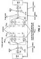
receiver device 141 totransmitter device 140 specifying antenna characteristics of phasedarray antenna 110, or vice versa. Figure 2 is a block diagram of one embodiment of an adaptive beam forming multiple antenna radio system containingtransmitter device 140 andreceiver device 141 ofFigure 1 . Transceiver 200 includes multiple independent transmit and receive chains. Transceiver 200 performs phased array beam forming using a phased array that takes an identical RF signal and shifts the phase for one or more antenna elements in the array to achieve beam steering.- Referring to
Figure 2 , Digital Signal Processor (DSP) 201 formats the content and generates real time baseband signals.DSP 201 may provide modulation, FEC coding, packet assembly, interleaving and automatic gain control. DSP 201 then forwards the baseband signals to be modulated and sent out on the RF portion of the transmitter. In one embodiment, the content is modulated into OFDM signals in a manner well known in the art.- Digital-to-analog converter (DAC) 202 receives the digital signals output from
DSP 201 and converts them to analog signals. In one embodiment, the signals output fromDAC 202 are between 0-256 MHz signals. Mixer 203 receives signals output fromDAC 202 and combines them with a signal from a local oscillator (LO) 204. The signals output frommixer 203 are at an intermediate frequency. In one embodiment, the intermediate frequency is between 2-9 GHz.- Multiple phase shifters 2050-N receive the output from
mixer 203. A demultiplier is included to control which phase shifters receive the signals. In one embodiment, these phase shifters are quantized phase shifters. In an alternative embodiment, the phase shifters may be replaced by complex multipliers. In one embodiment,DSP 201 also controls, viacontrol channel 208, the phase and magnitude of the currents in each of the antenna elements in phasedarray antenna 220 to produce a desired beam pattern in a manner well-known in the art. In other words,DSP 201 controls the phase shifters 2050-N of phasedarray antenna 220 to produce the desired pattern. - Each of phase shifters 2050-N produce an output that is sent to one of power amplifiers 2060-N, which amplify the signal. The amplified signals are sent to antenna array 207 which has multiple antenna elements 2070-N- In one embodiment, the signals transmitted from antennas 2070-N are radio frequency signals between 56-64 GHz. Thus, multiple beams are output from phased
array antenna 220. - With respect to the receiver, antennas 2100-N receive the wireless transmissions from antennas 2070-N and provide them to phase shifters 2110-N. As discussed above, in one embodiment, phase shifters 2110-N comprise quantitized phase shifters. Alternatively, phase shifters 2110-N may be replaced by complex multipliers. Phase shifters 2110-N receive the signals from antennas 2100-N, which are combined to form a single line feed output. In one embodiment, a multiplexer is used to combine the signals from the different elements and output the single feed line. The output of phase shifters 2110-N is input to intermediate frequency (IF)
amplifier 212, which reduces the frequency of the signal to an intermediate frequency. In one embodiment, the intermediate frequency is between 2-9 GHz. Mixer 213 receives the output of theIF amplifier 212 and combines it with a signal fromLO 214 in a manner well-known in the art. In one embodiment, the output ofmixer 213 is a signal in the range of 0-250 MHz. In one embodiment, there are I and Q signals for each channel.- Analog-to-digital converter (ADC) 215 receives the output of
mixer 213 and converts it to digital form. The digital output fromADC 215 is received byDSP 216.DSP 216 restores the amplitude and phase of the signal. DSPs 211 may provide demodulation, packet disassembly, de-interleaving and automatic gain control. - In one embodiment, each of the transceivers includes a controlling microprocessor that sets up control information for DSP. The controlling microprocessor may be on the same die as the DSP.
- In one embodiment, the DSPs implement an adaptive algorithm with the beam forming weights being implemented in hardware. That is, the transmitter and receiver work together to perform the beam forming in RF frequency using digitally controlled analog phase shifters; however, in an alternative embodiment, the beamforming is performed in IF. Phase shifters 2050-N and 2110-N are controlled via
control channel 208 andcontrol channel 217, respectfully, via their respective DSPs in a manner well known in the art. For example,DSP 201controls phase shifters 1050-N to have the transmitter perform adaptive beamforming to steer the beam while DSP 211 controls phase shifters 2110-N to direct antenna elements to receive the wireless transmission from antenna elements and combine the signals from different elements to form a single line feed output. In one embodiment, a multiplexer is used to combine the signals from the different elements and output the single feed line. DSP 201 performs the beam steering by pulsing, or energizing, the appropriate phase shifter connected to each antenna element. The pulsing algorithm underDSP 201 controls the phase and gain of each element. Performing DSP controlled phase array beamforming is well known in the art.- The adaptive beam forming antenna is used to avoid interfering obstructions. By adapting the beam forming and steering the beam, the communication can occur avoiding obstructions which may prevent or interfere with the wireless transmissions between the transmitter and the receiver.
- In one embodiment, with respect to the adaptive beamforming antennas, they have three phases of operations. The three phases of operations are the training phase, a searching phase, and a tracking phase. The training phase and searching phase occur during initialization. The training phase determines the channel profile with predetermined sequences of spatial patterns {Aî} and {Bĵ}. The searching phase computes a list of candidate spatial patterns {Aî}, {Bĵ} and selects a prime candidate {A0̂, B0̂} for use in the data transmission between the transmitter of one transceiver and the receiver of another. The tracking phase keeps track of the strength of the candidate list. When the prime candidate is obstructed, the next pair of spatial patterns is selected for use.
- In one embodiment, during the training phase, the transmitter sends out a sequence of spatial patterns { Aî}. For each spatial pattern {Aî}, the receiver projects the received signal onto another sequence of patterns {Bĵ}. As a result of the projection, a channel profile is obtained over the pair {Aî}, {Bĵ}.
- In one embodiment, an exhaustive training is performed between the transmitter and the receiver in which the antenna of the receiver is positioned at all locations and the transmitter sending multiple spatial patterns. Exhaustive training is well-known in the art. In this case, M transmit spatial patterns are transmitted by the transmitter and N received spatial patterns are received by the receiver to form an N by M channel matrix. Thus, the transmitter goes through a pattern of transmit sectors and the receiver searches to find the strongest signal for that transmission. Then the transmitter moves to the next sector. At the end of the exhaustive search process, a ranking of all the positions of the transmitter and the receiver and the signals strengths of the channel at those positions has been obtained. The information is maintained as pairs of positions of where the antennas are pointed and signal strengths of the channels. The list may be used to steer the antenna beam in case of interference.
- In an alternative embodiment, bi-section training is used in which the space is divided in successively narrow sections with orthogonal antenna patterns being sent to obtain a channel profile.
- Assuming
DSP 101 is in a stable state and the direction the antenna should point is already determined. In the nominal state, the DSP will have a set of coefficients that it sends the phase shifters. The coefficients indicate the amount of phase the phase shifter is to shift the signal for its corresponding antennas. For example,DSP 101 sends a set digital control information to the phase shifters that indicate the different phase shifters are to shift different amounts, e.g., shift 30 degrees, shift 45 degrees, shift 90 degrees, shift 180 degrees, etc. Thus, the signal that goes to that antenna element will be shifted by a certain number of degrees of phase. The end result of shifting, for example, 16, 34, 32, 64 elements in the array by different amounts enables the antenna to be steered in a direction that provides the most sensitive reception location for the receiving antenna. That is, the composite set of shifts over the entire antenna array provides the ability to stir where the most sensitive point of the antenna is pointing over the hemisphere. - Note that in one embodiment the appropriate connection between the transmitter and the receiver may not be a direct path from the transmitter to the receiver. For example, the most appropriate path may be to bounce off the ceiling.
- In one embodiment, the wireless communication system includes a back channel, or link, for transmitting information between wireless communication devices (e.g., a transmitter and receiver, a pair of transceivers, etc.). The information is related to the beamforming antennas and enables one or both of the wireless communication devices to adapt the array of antenna elements to better direct the antenna elements of a transmitter to the antenna elements of the receiving device together. The information also includes information to facilitate the use of the content being wirelessly transferred between the antenna elements of the transmitter and the receiver.
- In
Figure 2 ,back channel 220 is coupled betweenDSP 216 andDSP 201 to enableDSP 216 to send tracking and control information toDSP 201. In one embodiment,back channel 220 functions as a high speed downlink and an acknowledgement channel. - In one embodiment, the back channel is also used to transfer information corresponding to the application for which the wireless communication is occurring (e.g., wireless video). Such information includes content protection information. For example, in one embodiment, the back channel is used to transfer encryption information (e.g., encryption keys and acknowledgements of encryption keys) when the transceivers are transferring HDMI data. In such a case, the back channel is used for content protection communications.
- More specifically, in HDMI, encryption is used to validate that the data sink is a permitted device (e.g., a permitted display). There is a continuous stream of new encryption keys that is transferred while transferring the HDMI datastream to validate that the permitted device hasn't changed. Blocks of frames for the HD TV data are encrypted with different keys and then those keys have to be acknowledged back on
back channel 220 in order to validate the player.Back channel 220 transfers the encryption keys in the forward direction to the receiver and acknowledgements of key receipts from the receiver in the return direction. Thus, encrypted information is sent in both directions. - The use of the back channel for content protection communications is beneficial because it avoids having to complete a lengthy retraining process when such communications are sent along with content. For example, if a key from a transmitter is sent alongside the content flowing across the primary link and that primary link breaks, it will force a lengthy retrain of 2-3 seconds for a typical HDMI/HDCP system. In one embodiment, this separate bi-directional link that has higher reliability than the primary directional link given it's omni-directional orientation. By using this back channel for communication of the HDCP keys and the appropriate acknowledgement back from the receiving device, the time consuming retraining can be avoided even in the event of the most impactful obstruction.
- During the active period when the beamforming antennas are transferring content, the back channel is used to allow the receiver to notify the transmitter about the status of the channel. For example, while the channel between the beamforming antennas is of sufficient quality, the receiver sends information over the back channel to indicate that the channel is acceptable. The back channel may also be used by the receiver to send the transmitter quantifiable information indicating the quality of the channel being used. If some form of interference (e.g., an obstruction) occurs that degrades the quality of the channel below an acceptable level or prevents transmissions completely between the beamforming antennas, the receiver can indicate that the channel is no longer acceptable and/or can request a change in the channel over the back channel. The receiver may request a change to the next channel in a predetermined set of channels or may specify a specific channel for the transmitter to use.
- In one embodiment, the back channel is bi-directional. In such a case, in one embodiment, the transmitter uses the back channel to send information to the receiver. Such information may include information that instructs the receiver to position its antenna elements at different fixed locations that the transmitter would scan during initialization. The transmitter may specify this by specifically designating the location or by indicating that the receiver should proceed to the next location designated in a predetermined order or list through which both the transmitter and receiver are proceeding.
- In one embodiment, the back channel is used by either or both of the transmitter and the receiver to notify the other of specific antenna characterization information. For example, the antenna characterization information may specify that the antenna is capable of a resolution down to 6 degrees of radius and that the antenna has a certain number of elements (e.g., 32 elements, 64 elements, etc.).
- In one embodiment, communication on the back channel is performed wirelessly by using interface units. Any form of wireless communication may be used. In one embodiment, OFDM is used to transfer information over the back channel. In another embodiment, CPM is used to transfer information over the back channel.
- Whereas many alterations and modifications of the present invention will no doubt become apparent to a person of ordinary skill in the art after having read the foregoing description, it is to be understood that any particular embodiment shown and described by way of illustration is in no way intended to be considered limiting. Therefore, references to details of various embodiments are not intended to limit the scope of the invention as defined by the appended claims.
Claims (22)
- A transmitter device (140) comprising:a processor (103);a radio frequency, RF, transmitter having a digitally controlled phased array antenna (105) coupled to and controlled by the processor to transmit content using adaptive beamforming over a first wireless connection to a receiver device; andan interface (106) to a wireless communication channel (107) of a second wireless connection coupled to the processor, such that during initialization of the phased array antenna (105), the transmitter device can receive, via the wireless communication channel (107) antenna information comprising antenna location information and performance information corresponding to a location of a phased array antenna of the receiver device such that the transmitter device can select a direction to steer the beam formed by the phased array antenna (105) of the transmitter device;wherein when the phased array antenna of the transmitter device is operating in a mode during which content is transmitted, the transmitter device is arranged to receive, via the wireless communication channel, an indication of the status of the communication path from the receiver device,characterised in that the transmitter device is further arranged to communicate content protection information via the wireless communication channel to facilitate playing of the content, said content protection information comprising one or more of a group consisting of encryption keys sent by the processor of the transmitter device, and one or more acknowledgments received from the processor of the receiver device.
- The transmitter device defined in Claim 1 wherein the antenna location information and the performance information comprises one or more pairs that include an antenna position and the signal strength of the channel for that antenna position.
- The transmitter device defined in Claim 1 wherein the information to enable the processor to select a direction to steer the beam formed by the phased array antenna comprises information identifying one or more channels to be used by the processor.
- The transmitter device defined in Claim 1 wherein the indication of the status of communication from the RF transmitter comprises an indication to prompt the processor to steer the beam in another direction.
- The transmitter device defined in Claim 4 wherein the indication to prompt the processor to steer the beam in another direction is generated in response to interference with transmission of portions of the content.
- The transmitter device defined in Claim 4 wherein the indication to prompt the processor to steer the beam in another direction includes information specifying one or more alternative channels.
- The transmitter device defined in Claim 1 wherein the antenna information further comprises information specifying one or more characteristics of a receiver to receive the content.
- The transmitter device defined in Claim 1 wherein the wireless communication channel is bi-directional.
- The transmitter device defined in Claim 1 wherein the antenna information further comprises information sent by the processor to specify a location to which a receiver designated to receive the content is to direct its phased array antenna (110).
- The transmitter device defined in Claim 9 wherein the information specifying the location indicates the receiver to direct its phased array antenna to the next location in a predetermined location order.
- The transmitter device defined in Claim 1 wherein the antenna information indicates the quality of one or more channels and an indication from a receiver of the content to the processor to steer the beam to a different location.
- The transmitter device defined in Claim 1 wherein the processor is adapted to send digital control information to the phased array antenna to indicate an amount to shift one or more phase shifters in the phased array antenna.
- The transmitter device defined in Claim 12 wherein the digital control information comprises a set of coefficients.
- The transmitter device defined in Claim 1 wherein the processor comprises a digital signal processor.
- The transmitter device defined in Claim 1 wherein the processor generates baseband signals.
- The transmitter device defined in Claim 15 wherein the baseband signals are orthogonal frequency division multiplex, OFDM, signals.
- The transmitter device defined in Claim 1 further comprising:a digital-to-analog converter to convert baseband signals into analog signals at a first frequency; anda mixer to mix the analog signals with a signal from a local oscillator to produce adjusted analog signals with a second frequency higher than first frequency, the adjusted analog signals being sent to the phased array antenna for transmission thereby.
- The transmitter device defined in Claim 17 wherein the phased array antenna comprises:a demultiplexer coupled to receive the adjusted analog signals;a plurality of phase shifters coupled to the demultiplexer to shift the phase of the adjusted analog signals based on control signals from the processor;a plurality of amplifiers, wherein each of the plurality of amplifiers is coupled to an output of one of plurality of phase shifters; anda plurality of antennas, wherein each of the plurality of antennas is coupled to an output of one of plurality of amplifiers.
- The transmitter device defined in Claim 1 wherein the content adheres to the HDMI standard.
- The transmitter device defined in Claim 1 wherein the content adheres to the DVI standard.
- The transmitter device defined in Claim 1 wherein the transmitter is part of a transceiver.
- A receiver device comprising:a processor (112);a radio frequency, RF, receiver having a digitally controlled phased array antenna (110) coupled to and controlled by the processor (112) to receive content from a transmitter device (140) using adaptive beamforming over a first wireless connection; andan interface (109) to a wireless communication channel (107) of a second wireless connection coupled to the processor, such that during initialization of the phased array antenna (110), the receiver device can send, via the wireless communication channel (107), antenna information comprising antenna location information and performance information corresponding to a location of the phased array antenna of the receiver device such that the transmitter device can select a direction of its phased array antenna (105),wherein when the phased array antenna of the receiver device is operating in a mode during which content is received, the receiver device is arranged to transmit, via the wireless communication channel, an indication of the status of the communication path being received by the phased array antenna of the receiver device,characterised in that the receiver device is further arranged to communicate content protection information via the wireless communication channel to facilitate playing of the content, said content protection information comprising one or more of a group consisting of encryption keys received from the processor of the transmitter device, and one or more acknowledgements sent by the processor of the receiver device.
Applications Claiming Priority (2)
| Application Number | Priority Date | Filing Date | Title |
|---|---|---|---|
| US11/202,995US7904117B2 (en) | 2005-08-12 | 2005-08-12 | Wireless communication device using adaptive beamforming |
| PCT/US2006/031306WO2007021891A1 (en) | 2005-08-12 | 2006-08-11 | A wireless communication device using adaptive beamforming |
Publications (2)
| Publication Number | Publication Date |
|---|---|
| EP1922824A1 EP1922824A1 (en) | 2008-05-21 |
| EP1922824B1true EP1922824B1 (en) | 2020-03-04 |
Family
ID=37491957
Family Applications (1)
| Application Number | Title | Priority Date | Filing Date |
|---|---|---|---|
| EP06801212.9AActiveEP1922824B1 (en) | 2005-08-12 | 2006-08-11 | A wireless communication device using adaptive beamforming |
Country Status (9)
| Country | Link |
|---|---|
| US (1) | US7904117B2 (en) |
| EP (1) | EP1922824B1 (en) |
| JP (1) | JP5086259B2 (en) |
| KR (1) | KR101287780B1 (en) |
| CN (1) | CN101238649B (en) |
| AU (1) | AU2006279901B2 (en) |
| IL (1) | IL188931A0 (en) |
| RU (1) | RU2384946C2 (en) |
| WO (1) | WO2007021891A1 (en) |
Cited By (1)
| Publication number | Priority date | Publication date | Assignee | Title |
|---|---|---|---|---|
| US20240322431A1 (en)* | 2021-02-24 | 2024-09-26 | Bluehalo, Llc | System and method for a digitally beamformed phased array feed |
Families Citing this family (260)
| Publication number | Priority date | Publication date | Assignee | Title |
|---|---|---|---|---|
| JP3843102B2 (en)* | 2003-08-06 | 2006-11-08 | 本田技研工業株式会社 | Exhaust gas purification catalyst, method for producing the same, and exhaust gas purification catalyst device |
| US8014416B2 (en) | 2006-02-14 | 2011-09-06 | Sibeam, Inc. | HD physical layer of a wireless communication device |
| US7856104B2 (en)* | 2007-02-05 | 2010-12-21 | Sony Corporation | System and method for ensuring secure communication between TV and set back box |
| US8170522B2 (en)* | 2006-11-15 | 2012-05-01 | Sibeam, Inc. | Multi-transformer architecture for an active RF circuit |
| US20080112101A1 (en)* | 2006-11-15 | 2008-05-15 | Mcelwee Patrick T | Transmission line filter for esd protection |
| US8314736B2 (en) | 2008-03-31 | 2012-11-20 | Golba Llc | Determining the position of a mobile device using the characteristics of received signals and a reference database |
| US8744081B2 (en) | 2007-03-22 | 2014-06-03 | Qualcomm Incorporated | System and method for implementing content protection in a wireless digital system |
| US8170617B2 (en) | 2007-03-26 | 2012-05-01 | Sibeam, Inc. | Extensions to adaptive beam-steering method |
| US20080238621A1 (en)* | 2007-03-30 | 2008-10-02 | Broadcom Corporation | Multi-mode rfid reader architecture |
| KR101013065B1 (en)* | 2007-04-27 | 2011-02-14 | 삼성전자주식회사 | Apparatus and method for performing low power amplification in wireless communication system |
| US20080280574A1 (en)* | 2007-05-11 | 2008-11-13 | Broadcom Corporation, A California Corporation | RF transmitter with adjustable antenna assembly |
| US20080280581A1 (en)* | 2007-05-11 | 2008-11-13 | Broadcom Corporation, A California Corporation | RF receiver with adjustable antenna assembly |
| JP2008306232A (en)* | 2007-06-05 | 2008-12-18 | Funai Electric Co Ltd | Video receiver and broadcasting receiver |
| US11264841B2 (en) | 2007-06-14 | 2022-03-01 | Ossia Inc. | Wireless power transmission system |
| US8446248B2 (en)* | 2007-06-14 | 2013-05-21 | Omnilectric, Inc. | Wireless power transmission system |
| US8159364B2 (en) | 2007-06-14 | 2012-04-17 | Omnilectric, Inc. | Wireless power transmission system |
| EP2018085B1 (en)* | 2007-07-18 | 2010-10-20 | Sony Corporation | Improved contention based media access mechanism |
| US8165595B2 (en)* | 2008-01-25 | 2012-04-24 | Samsung Electronics Co., Ltd. | System and method for multi-stage antenna training of beamforming vectors |
| US8280445B2 (en) | 2008-02-13 | 2012-10-02 | Samsung Electronics Co., Ltd. | System and method for antenna training of beamforming vectors by selective use of beam level training |
| US7978659B2 (en)* | 2008-03-11 | 2011-07-12 | Intel Corporation | Method and apparatus of connectivity recovery in a wireless network |
| US7800541B2 (en) | 2008-03-31 | 2010-09-21 | Golba Llc | Methods and systems for determining the location of an electronic device |
| US9829560B2 (en) | 2008-03-31 | 2017-11-28 | Golba Llc | Determining the position of a mobile device using the characteristics of received signals and a reference database |
| US7970359B2 (en)* | 2008-07-29 | 2011-06-28 | Alvarion Ltd. | Delay diversity in antenna arrays |
| EP2392048B1 (en) | 2009-02-02 | 2018-10-31 | Commonwealth Scientific and Industrial Research Organisation | Hybrid adaptive antenna array |
| US8457026B1 (en)* | 2009-02-03 | 2013-06-04 | Sibeam, Inc. | Enhanced wireless data rates using multiple beams |
| JP5141587B2 (en) | 2009-02-13 | 2013-02-13 | ソニー株式会社 | COMMUNICATION DEVICE, COMMUNICATION CONTROL METHOD, AND COMMUNICATION SYSTEM |
| CN106535123A (en) | 2009-06-30 | 2017-03-22 | 诺基亚技术有限公司 | Apparatus and method |
| US8639270B2 (en) | 2010-08-06 | 2014-01-28 | Golba Llc | Method and system for device positioning utilizing distributed transceivers with array processing |
| US7965234B2 (en)* | 2009-08-06 | 2011-06-21 | Samsung Electro-Mechanics Co., Ltd. | Beamforming apparatus and method for multi-antenna system |
| KR101079549B1 (en)* | 2009-08-06 | 2011-11-02 | 고려대학교 산학협력단 | multi-antenna system using adaptive beamforming |
| US8630582B2 (en)* | 2009-09-02 | 2014-01-14 | Sony Corporation | Out-of-band radio link protocol and network architecture for a wireless network composed of wireless terminals with millimetre wave frequency range radio units |
| US9264111B2 (en)* | 2009-10-05 | 2016-02-16 | Simon Fraser University | Reassignment of data among subcarriers in wireless data communication |
| US8395712B2 (en) | 2009-10-28 | 2013-03-12 | Panasonic Corporation | Wireless receiving apparatus, wireless communication system, and method of supporting antenna installation |
| KR101075013B1 (en) | 2009-12-11 | 2011-10-19 | 전자부품연구원 | Rf vectormodulator for veamforming |
| US8660057B2 (en) | 2010-08-26 | 2014-02-25 | Golba, Llc | Method and system for distributed communication |
| US9037094B2 (en) | 2011-10-17 | 2015-05-19 | Golba Llc | Method and system for high-throughput and low-power communication links in a distributed transceiver network |
| EP2584651B1 (en) | 2011-10-18 | 2015-07-01 | Imec | Method for beamforming and device using the same |
| KR102062158B1 (en) | 2012-06-21 | 2020-01-03 | 삼성전자주식회사 | Communication device and orientation control method |
| US9948135B2 (en) | 2015-09-22 | 2018-04-17 | Energous Corporation | Systems and methods for identifying sensitive objects in a wireless charging transmission field |
| US9966765B1 (en) | 2013-06-25 | 2018-05-08 | Energous Corporation | Multi-mode transmitter |
| US9859797B1 (en) | 2014-05-07 | 2018-01-02 | Energous Corporation | Synchronous rectifier design for wireless power receiver |
| US9843213B2 (en) | 2013-08-06 | 2017-12-12 | Energous Corporation | Social power sharing for mobile devices based on pocket-forming |
| US10263432B1 (en) | 2013-06-25 | 2019-04-16 | Energous Corporation | Multi-mode transmitter with an antenna array for delivering wireless power and providing Wi-Fi access |
| US9991741B1 (en) | 2014-07-14 | 2018-06-05 | Energous Corporation | System for tracking and reporting status and usage information in a wireless power management system |
| US9876648B2 (en) | 2014-08-21 | 2018-01-23 | Energous Corporation | System and method to control a wireless power transmission system by configuration of wireless power transmission control parameters |
| US9143000B2 (en) | 2012-07-06 | 2015-09-22 | Energous Corporation | Portable wireless charging pad |
| US9838083B2 (en) | 2014-07-21 | 2017-12-05 | Energous Corporation | Systems and methods for communication with remote management systems |
| US9973021B2 (en) | 2012-07-06 | 2018-05-15 | Energous Corporation | Receivers for wireless power transmission |
| US9954374B1 (en) | 2014-05-23 | 2018-04-24 | Energous Corporation | System and method for self-system analysis for detecting a fault in a wireless power transmission Network |
| US20150326070A1 (en) | 2014-05-07 | 2015-11-12 | Energous Corporation | Methods and Systems for Maximum Power Point Transfer in Receivers |
| US20140008993A1 (en) | 2012-07-06 | 2014-01-09 | DvineWave Inc. | Methodology for pocket-forming |
| US9876379B1 (en) | 2013-07-11 | 2018-01-23 | Energous Corporation | Wireless charging and powering of electronic devices in a vehicle |
| US9843201B1 (en) | 2012-07-06 | 2017-12-12 | Energous Corporation | Wireless power transmitter that selects antenna sets for transmitting wireless power to a receiver based on location of the receiver, and methods of use thereof |
| US10992187B2 (en) | 2012-07-06 | 2021-04-27 | Energous Corporation | System and methods of using electromagnetic waves to wirelessly deliver power to electronic devices |
| US10199849B1 (en) | 2014-08-21 | 2019-02-05 | Energous Corporation | Method for automatically testing the operational status of a wireless power receiver in a wireless power transmission system |
| US9912199B2 (en) | 2012-07-06 | 2018-03-06 | Energous Corporation | Receivers for wireless power transmission |
| US10256657B2 (en) | 2015-12-24 | 2019-04-09 | Energous Corporation | Antenna having coaxial structure for near field wireless power charging |
| US10141791B2 (en) | 2014-05-07 | 2018-11-27 | Energous Corporation | Systems and methods for controlling communications during wireless transmission of power using application programming interfaces |
| US9831718B2 (en) | 2013-07-25 | 2017-11-28 | Energous Corporation | TV with integrated wireless power transmitter |
| US9923386B1 (en) | 2012-07-06 | 2018-03-20 | Energous Corporation | Systems and methods for wireless power transmission by modifying a number of antenna elements used to transmit power waves to a receiver |
| US9824815B2 (en) | 2013-05-10 | 2017-11-21 | Energous Corporation | Wireless charging and powering of healthcare gadgets and sensors |
| US10312715B2 (en) | 2015-09-16 | 2019-06-04 | Energous Corporation | Systems and methods for wireless power charging |
| US9899873B2 (en) | 2014-05-23 | 2018-02-20 | Energous Corporation | System and method for generating a power receiver identifier in a wireless power network |
| US10291055B1 (en) | 2014-12-29 | 2019-05-14 | Energous Corporation | Systems and methods for controlling far-field wireless power transmission based on battery power levels of a receiving device |
| US9368020B1 (en) | 2013-05-10 | 2016-06-14 | Energous Corporation | Off-premises alert system and method for wireless power receivers in a wireless power network |
| US9847679B2 (en) | 2014-05-07 | 2017-12-19 | Energous Corporation | System and method for controlling communication between wireless power transmitter managers |
| US10224758B2 (en) | 2013-05-10 | 2019-03-05 | Energous Corporation | Wireless powering of electronic devices with selective delivery range |
| US9438045B1 (en) | 2013-05-10 | 2016-09-06 | Energous Corporation | Methods and systems for maximum power point transfer in receivers |
| US9882430B1 (en) | 2014-05-07 | 2018-01-30 | Energous Corporation | Cluster management of transmitters in a wireless power transmission system |
| US9124125B2 (en) | 2013-05-10 | 2015-09-01 | Energous Corporation | Wireless power transmission with selective range |
| US10124754B1 (en) | 2013-07-19 | 2018-11-13 | Energous Corporation | Wireless charging and powering of electronic sensors in a vehicle |
| US10075008B1 (en) | 2014-07-14 | 2018-09-11 | Energous Corporation | Systems and methods for manually adjusting when receiving electronic devices are scheduled to receive wirelessly delivered power from a wireless power transmitter in a wireless power network |
| US10008889B2 (en) | 2014-08-21 | 2018-06-26 | Energous Corporation | Method for automatically testing the operational status of a wireless power receiver in a wireless power transmission system |
| US10230266B1 (en) | 2014-02-06 | 2019-03-12 | Energous Corporation | Wireless power receivers that communicate status data indicating wireless power transmission effectiveness with a transmitter using a built-in communications component of a mobile device, and methods of use thereof |
| US10063064B1 (en) | 2014-05-23 | 2018-08-28 | Energous Corporation | System and method for generating a power receiver identifier in a wireless power network |
| US10223717B1 (en) | 2014-05-23 | 2019-03-05 | Energous Corporation | Systems and methods for payment-based authorization of wireless power transmission service |
| US9847677B1 (en) | 2013-10-10 | 2017-12-19 | Energous Corporation | Wireless charging and powering of healthcare gadgets and sensors |
| US9893768B2 (en) | 2012-07-06 | 2018-02-13 | Energous Corporation | Methodology for multiple pocket-forming |
| US9793758B2 (en) | 2014-05-23 | 2017-10-17 | Energous Corporation | Enhanced transmitter using frequency control for wireless power transmission |
| US10211680B2 (en) | 2013-07-19 | 2019-02-19 | Energous Corporation | Method for 3 dimensional pocket-forming |
| US10211674B1 (en) | 2013-06-12 | 2019-02-19 | Energous Corporation | Wireless charging using selected reflectors |
| US10193396B1 (en) | 2014-05-07 | 2019-01-29 | Energous Corporation | Cluster management of transmitters in a wireless power transmission system |
| US10063105B2 (en) | 2013-07-11 | 2018-08-28 | Energous Corporation | Proximity transmitters for wireless power charging systems |
| US9939864B1 (en) | 2014-08-21 | 2018-04-10 | Energous Corporation | System and method to control a wireless power transmission system by configuration of wireless power transmission control parameters |
| US10186913B2 (en) | 2012-07-06 | 2019-01-22 | Energous Corporation | System and methods for pocket-forming based on constructive and destructive interferences to power one or more wireless power receivers using a wireless power transmitter including a plurality of antennas |
| US9893554B2 (en) | 2014-07-14 | 2018-02-13 | Energous Corporation | System and method for providing health safety in a wireless power transmission system |
| US10270261B2 (en) | 2015-09-16 | 2019-04-23 | Energous Corporation | Systems and methods of object detection in wireless power charging systems |
| US10063106B2 (en) | 2014-05-23 | 2018-08-28 | Energous Corporation | System and method for a self-system analysis in a wireless power transmission network |
| US10206185B2 (en) | 2013-05-10 | 2019-02-12 | Energous Corporation | System and methods for wireless power transmission to an electronic device in accordance with user-defined restrictions |
| US9887584B1 (en) | 2014-08-21 | 2018-02-06 | Energous Corporation | Systems and methods for a configuration web service to provide configuration of a wireless power transmitter within a wireless power transmission system |
| US9893555B1 (en) | 2013-10-10 | 2018-02-13 | Energous Corporation | Wireless charging of tools using a toolbox transmitter |
| US10211682B2 (en) | 2014-05-07 | 2019-02-19 | Energous Corporation | Systems and methods for controlling operation of a transmitter of a wireless power network based on user instructions received from an authenticated computing device powered or charged by a receiver of the wireless power network |
| US10128699B2 (en) | 2014-07-14 | 2018-11-13 | Energous Corporation | Systems and methods of providing wireless power using receiver device sensor inputs |
| US10141768B2 (en) | 2013-06-03 | 2018-11-27 | Energous Corporation | Systems and methods for maximizing wireless power transfer efficiency by instructing a user to change a receiver device's position |
| US20150162751A1 (en)* | 2013-05-10 | 2015-06-11 | DvineWave Inc. | Wireless charging of clothing and smart fabrics |
| US9941707B1 (en) | 2013-07-19 | 2018-04-10 | Energous Corporation | Home base station for multiple room coverage with multiple transmitters |
| US10965164B2 (en) | 2012-07-06 | 2021-03-30 | Energous Corporation | Systems and methods of wirelessly delivering power to a receiver device |
| US10103582B2 (en) | 2012-07-06 | 2018-10-16 | Energous Corporation | Transmitters for wireless power transmission |
| US9887739B2 (en) | 2012-07-06 | 2018-02-06 | Energous Corporation | Systems and methods for wireless power transmission by comparing voltage levels associated with power waves transmitted by antennas of a plurality of antennas of a transmitter to determine appropriate phase adjustments for the power waves |
| US10291066B1 (en) | 2014-05-07 | 2019-05-14 | Energous Corporation | Power transmission control systems and methods |
| US9900057B2 (en) | 2012-07-06 | 2018-02-20 | Energous Corporation | Systems and methods for assigning groups of antenas of a wireless power transmitter to different wireless power receivers, and determining effective phases to use for wirelessly transmitting power using the assigned groups of antennas |
| US11502551B2 (en) | 2012-07-06 | 2022-11-15 | Energous Corporation | Wirelessly charging multiple wireless-power receivers using different subsets of an antenna array to focus energy at different locations |
| US9906065B2 (en) | 2012-07-06 | 2018-02-27 | Energous Corporation | Systems and methods of transmitting power transmission waves based on signals received at first and second subsets of a transmitter's antenna array |
| US9882427B2 (en) | 2013-05-10 | 2018-01-30 | Energous Corporation | Wireless power delivery using a base station to control operations of a plurality of wireless power transmitters |
| US9252628B2 (en) | 2013-05-10 | 2016-02-02 | Energous Corporation | Laptop computer as a transmitter for wireless charging |
| US10090886B1 (en) | 2014-07-14 | 2018-10-02 | Energous Corporation | System and method for enabling automatic charging schedules in a wireless power network to one or more devices |
| US9787103B1 (en) | 2013-08-06 | 2017-10-10 | Energous Corporation | Systems and methods for wirelessly delivering power to electronic devices that are unable to communicate with a transmitter |
| US9859756B2 (en) | 2012-07-06 | 2018-01-02 | Energous Corporation | Transmittersand methods for adjusting wireless power transmission based on information from receivers |
| US10050462B1 (en) | 2013-08-06 | 2018-08-14 | Energous Corporation | Social power sharing for mobile devices based on pocket-forming |
| US10148097B1 (en) | 2013-11-08 | 2018-12-04 | Energous Corporation | Systems and methods for using a predetermined number of communication channels of a wireless power transmitter to communicate with different wireless power receivers |
| US10128693B2 (en) | 2014-07-14 | 2018-11-13 | Energous Corporation | System and method for providing health safety in a wireless power transmission system |
| US10038337B1 (en) | 2013-09-16 | 2018-07-31 | Energous Corporation | Wireless power supply for rescue devices |
| US9853692B1 (en) | 2014-05-23 | 2017-12-26 | Energous Corporation | Systems and methods for wireless power transmission |
| US9853458B1 (en) | 2014-05-07 | 2017-12-26 | Energous Corporation | Systems and methods for device and power receiver pairing |
| US10992185B2 (en) | 2012-07-06 | 2021-04-27 | Energous Corporation | Systems and methods of using electromagnetic waves to wirelessly deliver power to game controllers |
| US9812890B1 (en) | 2013-07-11 | 2017-11-07 | Energous Corporation | Portable wireless charging pad |
| US12057715B2 (en) | 2012-07-06 | 2024-08-06 | Energous Corporation | Systems and methods of wirelessly delivering power to a wireless-power receiver device in response to a change of orientation of the wireless-power receiver device |
| US10205239B1 (en) | 2014-05-07 | 2019-02-12 | Energous Corporation | Compact PIFA antenna |
| US10199835B2 (en) | 2015-12-29 | 2019-02-05 | Energous Corporation | Radar motion detection using stepped frequency in wireless power transmission system |
| US10439448B2 (en) | 2014-08-21 | 2019-10-08 | Energous Corporation | Systems and methods for automatically testing the communication between wireless power transmitter and wireless power receiver |
| US9941754B2 (en) | 2012-07-06 | 2018-04-10 | Energous Corporation | Wireless power transmission with selective range |
| US9876394B1 (en) | 2014-05-07 | 2018-01-23 | Energous Corporation | Boost-charger-boost system for enhanced power delivery |
| US9806564B2 (en) | 2014-05-07 | 2017-10-31 | Energous Corporation | Integrated rectifier and boost converter for wireless power transmission |
| US9941747B2 (en) | 2014-07-14 | 2018-04-10 | Energous Corporation | System and method for manually selecting and deselecting devices to charge in a wireless power network |
| US10243414B1 (en) | 2014-05-07 | 2019-03-26 | Energous Corporation | Wearable device with wireless power and payload receiver |
| US9859757B1 (en) | 2013-07-25 | 2018-01-02 | Energous Corporation | Antenna tile arrangements in electronic device enclosures |
| US9825674B1 (en) | 2014-05-23 | 2017-11-21 | Energous Corporation | Enhanced transmitter that selects configurations of antenna elements for performing wireless power transmission and receiving functions |
| US10090699B1 (en) | 2013-11-01 | 2018-10-02 | Energous Corporation | Wireless powered house |
| US10381880B2 (en) | 2014-07-21 | 2019-08-13 | Energous Corporation | Integrated antenna structure arrays for wireless power transmission |
| US9867062B1 (en) | 2014-07-21 | 2018-01-09 | Energous Corporation | System and methods for using a remote server to authorize a receiving device that has requested wireless power and to determine whether another receiving device should request wireless power in a wireless power transmission system |
| US9891669B2 (en) | 2014-08-21 | 2018-02-13 | Energous Corporation | Systems and methods for a configuration web service to provide configuration of a wireless power transmitter within a wireless power transmission system |
| US9871398B1 (en) | 2013-07-01 | 2018-01-16 | Energous Corporation | Hybrid charging method for wireless power transmission based on pocket-forming |
| US10224982B1 (en) | 2013-07-11 | 2019-03-05 | Energous Corporation | Wireless power transmitters for transmitting wireless power and tracking whether wireless power receivers are within authorized locations |
| US10218227B2 (en) | 2014-05-07 | 2019-02-26 | Energous Corporation | Compact PIFA antenna |
| US9899861B1 (en) | 2013-10-10 | 2018-02-20 | Energous Corporation | Wireless charging methods and systems for game controllers, based on pocket-forming |
| CN102801455B (en) | 2012-07-31 | 2015-12-16 | 华为技术有限公司 | Wave beam method for generating codebooks, beam search method and relevant apparatus |
| US9197982B2 (en) | 2012-08-08 | 2015-11-24 | Golba Llc | Method and system for distributed transceivers for distributed access points connectivity |
| JP2014060616A (en)* | 2012-09-18 | 2014-04-03 | Samsung Electronics Co Ltd | Communication device and signal detection method |
| CN102917397A (en)* | 2012-09-29 | 2013-02-06 | 东南大学 | Measuring device and measuring method for wireless channel on basis of phased antenna array |
| CN107196692B (en) | 2013-02-22 | 2021-08-17 | 欧希亚有限公司 | Method and wireless transmitter for wireless transmission of focus data |
| US9537357B2 (en) | 2013-05-10 | 2017-01-03 | Energous Corporation | Wireless sound charging methods and systems for game controllers, based on pocket-forming |
| US9843763B2 (en) | 2013-05-10 | 2017-12-12 | Energous Corporation | TV system with wireless power transmitter |
| US9538382B2 (en) | 2013-05-10 | 2017-01-03 | Energous Corporation | System and method for smart registration of wireless power receivers in a wireless power network |
| US9866279B2 (en) | 2013-05-10 | 2018-01-09 | Energous Corporation | Systems and methods for selecting which power transmitter should deliver wireless power to a receiving device in a wireless power delivery network |
| US9419443B2 (en) | 2013-05-10 | 2016-08-16 | Energous Corporation | Transducer sound arrangement for pocket-forming |
| US9819230B2 (en) | 2014-05-07 | 2017-11-14 | Energous Corporation | Enhanced receiver for wireless power transmission |
| US10103552B1 (en) | 2013-06-03 | 2018-10-16 | Energous Corporation | Protocols for authenticated wireless power transmission |
| US10003211B1 (en) | 2013-06-17 | 2018-06-19 | Energous Corporation | Battery life of portable electronic devices |
| US10021523B2 (en) | 2013-07-11 | 2018-07-10 | Energous Corporation | Proximity transmitters for wireless power charging systems |
| US9979440B1 (en) | 2013-07-25 | 2018-05-22 | Energous Corporation | Antenna tile arrangements configured to operate as one functional unit |
| US10075017B2 (en) | 2014-02-06 | 2018-09-11 | Energous Corporation | External or internal wireless power receiver with spaced-apart antenna elements for charging or powering mobile devices using wirelessly delivered power |
| US9935482B1 (en) | 2014-02-06 | 2018-04-03 | Energous Corporation | Wireless power transmitters that transmit at determined times based on power availability and consumption at a receiving mobile device |
| JP6202509B2 (en)* | 2014-04-02 | 2017-09-27 | ホアウェイ・テクノロジーズ・カンパニー・リミテッド | Communication method and apparatus using beam forming |
| US10158257B2 (en) | 2014-05-01 | 2018-12-18 | Energous Corporation | System and methods for using sound waves to wirelessly deliver power to electronic devices |
| US9966784B2 (en) | 2014-06-03 | 2018-05-08 | Energous Corporation | Systems and methods for extending battery life of portable electronic devices charged by sound |
| US9800172B1 (en) | 2014-05-07 | 2017-10-24 | Energous Corporation | Integrated rectifier and boost converter for boosting voltage received from wireless power transmission waves |
| US10153645B1 (en) | 2014-05-07 | 2018-12-11 | Energous Corporation | Systems and methods for designating a master power transmitter in a cluster of wireless power transmitters |
| US9973008B1 (en) | 2014-05-07 | 2018-05-15 | Energous Corporation | Wireless power receiver with boost converters directly coupled to a storage element |
| US10153653B1 (en) | 2014-05-07 | 2018-12-11 | Energous Corporation | Systems and methods for using application programming interfaces to control communications between a transmitter and a receiver |
| US10170917B1 (en) | 2014-05-07 | 2019-01-01 | Energous Corporation | Systems and methods for managing and controlling a wireless power network by establishing time intervals during which receivers communicate with a transmitter |
| US9876536B1 (en) | 2014-05-23 | 2018-01-23 | Energous Corporation | Systems and methods for assigning groups of antennas to transmit wireless power to different wireless power receivers |
| US10068703B1 (en) | 2014-07-21 | 2018-09-04 | Energous Corporation | Integrated miniature PIFA with artificial magnetic conductor metamaterials |
| US9871301B2 (en) | 2014-07-21 | 2018-01-16 | Energous Corporation | Integrated miniature PIFA with artificial magnetic conductor metamaterials |
| US10116143B1 (en) | 2014-07-21 | 2018-10-30 | Energous Corporation | Integrated antenna arrays for wireless power transmission |
| US9965009B1 (en) | 2014-08-21 | 2018-05-08 | Energous Corporation | Systems and methods for assigning a power receiver to individual power transmitters based on location of the power receiver |
| US9917477B1 (en) | 2014-08-21 | 2018-03-13 | Energous Corporation | Systems and methods for automatically testing the communication between power transmitter and wireless receiver |
| US10122415B2 (en) | 2014-12-27 | 2018-11-06 | Energous Corporation | Systems and methods for assigning a set of antennas of a wireless power transmitter to a wireless power receiver based on a location of the wireless power receiver |
| CN104639222A (en)* | 2015-02-03 | 2015-05-20 | 芜湖航飞科技股份有限公司 | Self-adaptive beam forming method of intelligent antenna |
| US9893535B2 (en) | 2015-02-13 | 2018-02-13 | Energous Corporation | Systems and methods for determining optimal charging positions to maximize efficiency of power received from wirelessly delivered sound wave energy |
| US12283828B2 (en) | 2015-09-15 | 2025-04-22 | Energous Corporation | Receiver devices configured to determine location within a transmission field |
| US10523033B2 (en) | 2015-09-15 | 2019-12-31 | Energous Corporation | Receiver devices configured to determine location within a transmission field |
| US9906275B2 (en) | 2015-09-15 | 2018-02-27 | Energous Corporation | Identifying receivers in a wireless charging transmission field |
| US10778041B2 (en) | 2015-09-16 | 2020-09-15 | Energous Corporation | Systems and methods for generating power waves in a wireless power transmission system |
| US10199850B2 (en) | 2015-09-16 | 2019-02-05 | Energous Corporation | Systems and methods for wirelessly transmitting power from a transmitter to a receiver by determining refined locations of the receiver in a segmented transmission field associated with the transmitter |
| US9941752B2 (en) | 2015-09-16 | 2018-04-10 | Energous Corporation | Systems and methods of object detection in wireless power charging systems |
| US9893538B1 (en) | 2015-09-16 | 2018-02-13 | Energous Corporation | Systems and methods of object detection in wireless power charging systems |
| US10186893B2 (en) | 2015-09-16 | 2019-01-22 | Energous Corporation | Systems and methods for real time or near real time wireless communications between a wireless power transmitter and a wireless power receiver |
| US10158259B1 (en) | 2015-09-16 | 2018-12-18 | Energous Corporation | Systems and methods for identifying receivers in a transmission field by transmitting exploratory power waves towards different segments of a transmission field |
| US10008875B1 (en) | 2015-09-16 | 2018-06-26 | Energous Corporation | Wireless power transmitter configured to transmit power waves to a predicted location of a moving wireless power receiver |
| US11710321B2 (en) | 2015-09-16 | 2023-07-25 | Energous Corporation | Systems and methods of object detection in wireless power charging systems |
| US10211685B2 (en) | 2015-09-16 | 2019-02-19 | Energous Corporation | Systems and methods for real or near real time wireless communications between a wireless power transmitter and a wireless power receiver |
| US9871387B1 (en) | 2015-09-16 | 2018-01-16 | Energous Corporation | Systems and methods of object detection using one or more video cameras in wireless power charging systems |
| US10128686B1 (en) | 2015-09-22 | 2018-11-13 | Energous Corporation | Systems and methods for identifying receiver locations using sensor technologies |
| US10153660B1 (en) | 2015-09-22 | 2018-12-11 | Energous Corporation | Systems and methods for preconfiguring sensor data for wireless charging systems |
| US10050470B1 (en) | 2015-09-22 | 2018-08-14 | Energous Corporation | Wireless power transmission device having antennas oriented in three dimensions |
| US10033222B1 (en) | 2015-09-22 | 2018-07-24 | Energous Corporation | Systems and methods for determining and generating a waveform for wireless power transmission waves |
| US10020678B1 (en) | 2015-09-22 | 2018-07-10 | Energous Corporation | Systems and methods for selecting antennas to generate and transmit power transmission waves |
| US10027168B2 (en) | 2015-09-22 | 2018-07-17 | Energous Corporation | Systems and methods for generating and transmitting wireless power transmission waves using antennas having a spacing that is selected by the transmitter |
| US10135294B1 (en) | 2015-09-22 | 2018-11-20 | Energous Corporation | Systems and methods for preconfiguring transmission devices for power wave transmissions based on location data of one or more receivers |
| US10135295B2 (en) | 2015-09-22 | 2018-11-20 | Energous Corporation | Systems and methods for nullifying energy levels for wireless power transmission waves |
| US10734717B2 (en) | 2015-10-13 | 2020-08-04 | Energous Corporation | 3D ceramic mold antenna |
| US10333332B1 (en) | 2015-10-13 | 2019-06-25 | Energous Corporation | Cross-polarized dipole antenna |
| US9899744B1 (en) | 2015-10-28 | 2018-02-20 | Energous Corporation | Antenna for wireless charging systems |
| US9853485B2 (en) | 2015-10-28 | 2017-12-26 | Energous Corporation | Antenna for wireless charging systems |
| US10027180B1 (en) | 2015-11-02 | 2018-07-17 | Energous Corporation | 3D triple linear antenna that acts as heat sink |
| US10063108B1 (en) | 2015-11-02 | 2018-08-28 | Energous Corporation | Stamped three-dimensional antenna |
| US10135112B1 (en) | 2015-11-02 | 2018-11-20 | Energous Corporation | 3D antenna mount |
| US11863001B2 (en) | 2015-12-24 | 2024-01-02 | Energous Corporation | Near-field antenna for wireless power transmission with antenna elements that follow meandering patterns |
| US10256677B2 (en) | 2016-12-12 | 2019-04-09 | Energous Corporation | Near-field RF charging pad with adaptive loading to efficiently charge an electronic device at any position on the pad |
| US10320446B2 (en) | 2015-12-24 | 2019-06-11 | Energous Corporation | Miniaturized highly-efficient designs for near-field power transfer system |
| US10116162B2 (en) | 2015-12-24 | 2018-10-30 | Energous Corporation | Near field transmitters with harmonic filters for wireless power charging |
| US10079515B2 (en) | 2016-12-12 | 2018-09-18 | Energous Corporation | Near-field RF charging pad with multi-band antenna element with adaptive loading to efficiently charge an electronic device at any position on the pad |
| US10027159B2 (en) | 2015-12-24 | 2018-07-17 | Energous Corporation | Antenna for transmitting wireless power signals |
| US10038332B1 (en) | 2015-12-24 | 2018-07-31 | Energous Corporation | Systems and methods of wireless power charging through multiple receiving devices |
| US10008886B2 (en) | 2015-12-29 | 2018-06-26 | Energous Corporation | Modular antennas with heat sinks in wireless power transmission systems |
| CA3010228C (en)* | 2015-12-31 | 2023-10-31 | Huawei Technologies Co., Ltd. | Beamforming method, receiver, transmitter, and system |
| US10657674B2 (en) | 2016-06-17 | 2020-05-19 | Immersive Robotics Pty Ltd. | Image compression method and apparatus |
| US20180062260A1 (en) | 2016-08-26 | 2018-03-01 | Analog Devices Global | Antenna array calibration systems and methods |
| US10923954B2 (en) | 2016-11-03 | 2021-02-16 | Energous Corporation | Wireless power receiver with a synchronous rectifier |
| KR102185600B1 (en) | 2016-12-12 | 2020-12-03 | 에너저스 코포레이션 | A method of selectively activating antenna zones of a near field charging pad to maximize transmitted wireless power |
| US10680319B2 (en) | 2017-01-06 | 2020-06-09 | Energous Corporation | Devices and methods for reducing mutual coupling effects in wireless power transmission systems |
| US10389161B2 (en) | 2017-03-15 | 2019-08-20 | Energous Corporation | Surface mount dielectric antennas for wireless power transmitters |
| US10439442B2 (en) | 2017-01-24 | 2019-10-08 | Energous Corporation | Microstrip antennas for wireless power transmitters |
| EP3579941A4 (en)* | 2017-02-08 | 2020-10-28 | Immersive Robotics Pty Ltd | ANTENNA CONTROL FOR MOBILE DEVICE COMMUNICATION |
| WO2018145154A1 (en)* | 2017-02-08 | 2018-08-16 | Immersive Robotics Pty Ltd | Displaying content to users in a multiplayer venue |
| US11011942B2 (en) | 2017-03-30 | 2021-05-18 | Energous Corporation | Flat antennas having two or more resonant frequencies for use in wireless power transmission systems |
| US10511097B2 (en) | 2017-05-12 | 2019-12-17 | Energous Corporation | Near-field antennas for accumulating energy at a near-field distance with minimal far-field gain |
| US11462949B2 (en) | 2017-05-16 | 2022-10-04 | Wireless electrical Grid LAN, WiGL Inc | Wireless charging method and system |
| US12074460B2 (en) | 2017-05-16 | 2024-08-27 | Wireless Electrical Grid Lan, Wigl Inc. | Rechargeable wireless power bank and method of using |
| US12074452B2 (en) | 2017-05-16 | 2024-08-27 | Wireless Electrical Grid Lan, Wigl Inc. | Networked wireless charging system |
| US12096031B2 (en) | 2017-06-05 | 2024-09-17 | Immersive Robotics Pty Ltd. | Method and apparatus for digital content stream compression and decompression |
| US10848853B2 (en) | 2017-06-23 | 2020-11-24 | Energous Corporation | Systems, methods, and devices for utilizing a wire of a sound-producing device as an antenna for receipt of wirelessly delivered power |
| CN107169482A (en)* | 2017-07-07 | 2017-09-15 | 合肥芯福传感器技术有限公司 | One kind encryption phased array fingerprint sensor |
| US10484078B2 (en) | 2017-07-11 | 2019-11-19 | Movandi Corporation | Reconfigurable and modular active repeater device |
| TWI801384B (en)* | 2017-09-01 | 2023-05-11 | 澳大利亞商伊門斯機器人控股有限公司 | System and method of antenna control for mobile device communication |
| US10122219B1 (en) | 2017-10-10 | 2018-11-06 | Energous Corporation | Systems, methods, and devices for using a battery as a antenna for receiving wirelessly delivered power from radio frequency power waves |
| US11342798B2 (en) | 2017-10-30 | 2022-05-24 | Energous Corporation | Systems and methods for managing coexistence of wireless-power signals and data signals operating in a same frequency band |
| AU2018373495B2 (en) | 2017-11-21 | 2023-01-05 | Immersive Robotics Pty Ltd | Frequency component selection for image compression |
| US11153604B2 (en) | 2017-11-21 | 2021-10-19 | Immersive Robotics Pty Ltd | Image compression for digital reality |
| EP3502732B1 (en)* | 2017-12-21 | 2021-10-20 | Nxp B.V. | Radar unit and method for detecting an existence of interference in a radar unit |
| US10637518B2 (en) | 2018-01-30 | 2020-04-28 | Mediatek Inc. | Wireless communication device with frequency planning for spur avoidance under coexistence of multiple wireless communication systems |
| US10615647B2 (en) | 2018-02-02 | 2020-04-07 | Energous Corporation | Systems and methods for detecting wireless power receivers and other objects at a near-field charging pad |
| US11177567B2 (en) | 2018-02-23 | 2021-11-16 | Analog Devices Global Unlimited Company | Antenna array calibration systems and methods |
| US11923924B2 (en)* | 2018-02-26 | 2024-03-05 | Parallel Wireless, Inc. | Miniature antenna array with polar combining architecture |
| US11159057B2 (en) | 2018-03-14 | 2021-10-26 | Energous Corporation | Loop antennas with selectively-activated feeds to control propagation patterns of wireless power signals |
| US11515732B2 (en) | 2018-06-25 | 2022-11-29 | Energous Corporation | Power wave transmission techniques to focus wirelessly delivered power at a receiving device |
| EP3815259A1 (en) | 2018-06-27 | 2021-05-05 | Telefonaktiebolaget LM Ericsson (publ) | Method and apparatus for beamforming control in a wireless communication network |
| RU2695050C1 (en)* | 2018-07-23 | 2019-07-18 | Павел Владимирович Лебедев | Method of generating an encryption/decryption key |
| US11437735B2 (en) | 2018-11-14 | 2022-09-06 | Energous Corporation | Systems for receiving electromagnetic energy using antennas that are minimally affected by the presence of the human body |
| US11539243B2 (en) | 2019-01-28 | 2022-12-27 | Energous Corporation | Systems and methods for miniaturized antenna for wireless power transmissions |
| EP3921945A1 (en) | 2019-02-06 | 2021-12-15 | Energous Corporation | Systems and methods of estimating optimal phases to use for individual antennas in an antenna array |
| US11404779B2 (en) | 2019-03-14 | 2022-08-02 | Analog Devices International Unlimited Company | On-chip phased array calibration systems and methods |
| US12155231B2 (en) | 2019-04-09 | 2024-11-26 | Energous Corporation | Asymmetric spiral antennas for wireless power transmission and reception |
| CN114731061A (en) | 2019-09-20 | 2022-07-08 | 艾诺格思公司 | Classifying and detecting foreign objects using a power amplifier controller integrated circuit in a wireless power transmission system |
| WO2021055899A1 (en) | 2019-09-20 | 2021-03-25 | Energous Corporation | Systems and methods of protecting wireless power receivers using multiple rectifiers and establishing in-band communications using multiple rectifiers |
| WO2021055898A1 (en) | 2019-09-20 | 2021-03-25 | Energous Corporation | Systems and methods for machine learning based foreign object detection for wireless power transmission |
| WO2021055901A1 (en) | 2019-09-20 | 2021-03-25 | Energous Corporation | Asymmetric spiral antennas with parasitic elements for wireless power transmission |
| US11381118B2 (en) | 2019-09-20 | 2022-07-05 | Energous Corporation | Systems and methods for machine learning based foreign object detection for wireless power transmission |
| US12355984B2 (en) | 2019-10-18 | 2025-07-08 | Immersive Robotics Pty Ltd | Content compression for network transmission |
| US11355966B2 (en) | 2019-12-13 | 2022-06-07 | Energous Corporation | Charging pad with guiding contours to align an electronic device on the charging pad and efficiently transfer near-field radio-frequency energy to the electronic device |
| US10985617B1 (en) | 2019-12-31 | 2021-04-20 | Energous Corporation | System for wirelessly transmitting energy at a near-field distance without using beam-forming control |
| US11450952B2 (en) | 2020-02-26 | 2022-09-20 | Analog Devices International Unlimited Company | Beamformer automatic calibration systems and methods |
| US11799324B2 (en) | 2020-04-13 | 2023-10-24 | Energous Corporation | Wireless-power transmitting device for creating a uniform near-field charging area |
| US11469629B2 (en) | 2020-08-12 | 2022-10-11 | Energous Corporation | Systems and methods for secure wireless transmission of power using unidirectional communication signals from a wireless-power-receiving device |
| US12306285B2 (en) | 2020-12-01 | 2025-05-20 | Energous Corporation | Systems and methods for using one or more sensors to detect and classify objects in a keep-out zone of a wireless-power transmission field, and antennas with integrated sensor arrangements |
| US11916702B2 (en)* | 2021-12-20 | 2024-02-27 | Qualcomm Incorporated | Tone reservation for digital post distortion |
| US11916398B2 (en) | 2021-12-29 | 2024-02-27 | Energous Corporation | Small form-factor devices with integrated and modular harvesting receivers, and shelving-mounted wireless-power transmitters for use therewith |
| US12142939B2 (en) | 2022-05-13 | 2024-11-12 | Energous Corporation | Integrated wireless-power-transmission platform designed to operate in multiple bands, and multi-band antennas for use therewith |
| US12323207B2 (en)* | 2022-09-13 | 2025-06-03 | Qualcomm Incorporated | Beamforming for backscatter radio |
| CN119172505A (en)* | 2024-09-12 | 2024-12-20 | 天津大学 | Phased array stationary target video transmission verification system |
Citations (2)
| Publication number | Priority date | Publication date | Assignee | Title |
|---|---|---|---|---|
| US20030161410A1 (en)* | 2002-02-26 | 2003-08-28 | Martin Smith | Radio communications device with adaptive combination |
| US20050136990A1 (en)* | 2003-12-22 | 2005-06-23 | Sony Corporation | Method and system for wireless digital multimedia presentation |
Family Cites Families (19)
| Publication number | Priority date | Publication date | Assignee | Title |
|---|---|---|---|---|
| US5634199A (en) | 1993-04-14 | 1997-05-27 | Stanford University | Method of subspace beamforming using adaptive transmitting antennas with feedback |
| JPH08321799A (en)* | 1995-05-25 | 1996-12-03 | Nippondenso Co Ltd | Radio communication equipment and communication system |
| US5680142A (en) | 1995-11-07 | 1997-10-21 | Smith; David Anthony | Communication system and method utilizing an antenna having adaptive characteristics |
| JP2000078555A (en)* | 1998-08-28 | 2000-03-14 | Sony Corp | Charging method and device for data transmission system |
| CN1235391A (en)* | 1999-04-19 | 1999-11-17 | 董捷 | Self adaptable array antenna for pre-optimized shape beam for code division multi-access system |
| CN1191715C (en)* | 1999-08-24 | 2005-03-02 | 通用仪器公司 | System and method for protecting on-demand delivery of pre-encrypted content with rights control message suppression |
| KR100615887B1 (en)* | 2000-04-07 | 2006-08-25 | 삼성전자주식회사 | Wireless communication system having feedback function and method thereof |
| JP3743796B2 (en)* | 2000-06-20 | 2006-02-08 | 松下電器産業株式会社 | Broadcast reception system |
| KR100493152B1 (en)* | 2000-07-21 | 2005-06-02 | 삼성전자주식회사 | Transmission antenna diversity method, base station apparatus and mobile station apparatus therefor in mobile communication system |
| GB0102384D0 (en)* | 2001-01-31 | 2001-03-14 | Secr Defence | Signal detection using a phased array antenna |
| US20030060218A1 (en)* | 2001-07-27 | 2003-03-27 | Logitech Europe S.A. | Automated tuning of wireless peripheral devices |
| RU2232485C2 (en) | 2001-11-27 | 2004-07-10 | Корпорация "Самсунг Электроникс" | Procedure to form directivity pattern of antenna and device for its realization |
| US7283566B2 (en)* | 2002-06-14 | 2007-10-16 | Silicon Image, Inc. | Method and circuit for generating time stamp data from an embedded-clock audio data stream and a video clock |
| JP2004236136A (en)* | 2003-01-31 | 2004-08-19 | Mitsubishi Electric Corp | Mobile communication terminal, communication system, and decryption key supply method |
| KR100571862B1 (en)* | 2003-02-17 | 2006-04-17 | 삼성전자주식회사 | Mobile communication system including multiple antennas and method thereof |
| US7965837B2 (en) | 2003-04-30 | 2011-06-21 | Sony Corporation | Method and system for wireless digital video presentation |
| US7583982B2 (en)* | 2004-08-06 | 2009-09-01 | Interdigital Technology Corporation | Method and apparatus to improve channel quality for use in wireless communications systems with multiple-input multiple-output (MIMO) antennas |
| US7397425B2 (en)* | 2004-12-30 | 2008-07-08 | Microsoft Corporation | Electronically steerable sector antenna |
| US20060209892A1 (en)* | 2005-03-15 | 2006-09-21 | Radiospire Networks, Inc. | System, method and apparatus for wirelessly providing a display data channel between a generalized content source and a generalized content sink |
- 2005
- 2005-08-12USUS11/202,995patent/US7904117B2/ennot_activeExpired - Lifetime
- 2006
- 2006-08-11RURU2008109239/09Apatent/RU2384946C2/enactive
- 2006-08-11AUAU2006279901Apatent/AU2006279901B2/ennot_activeCeased
- 2006-08-11JPJP2008526219Apatent/JP5086259B2/ennot_activeExpired - Fee Related
- 2006-08-11EPEP06801212.9Apatent/EP1922824B1/enactiveActive
- 2006-08-11KRKR1020087005965Apatent/KR101287780B1/ennot_activeExpired - Fee Related
- 2006-08-11WOPCT/US2006/031306patent/WO2007021891A1/enactiveApplication Filing
- 2006-08-11CNCN2006800287255Apatent/CN101238649B/enactiveActive
- 2008
- 2008-01-22ILIL188931Apatent/IL188931A0/enactiveIP Right Grant
Patent Citations (2)
| Publication number | Priority date | Publication date | Assignee | Title |
|---|---|---|---|---|
| US20030161410A1 (en)* | 2002-02-26 | 2003-08-28 | Martin Smith | Radio communications device with adaptive combination |
| US20050136990A1 (en)* | 2003-12-22 | 2005-06-23 | Sony Corporation | Method and system for wireless digital multimedia presentation |
Cited By (2)
| Publication number | Priority date | Publication date | Assignee | Title |
|---|---|---|---|---|
| US20240322431A1 (en)* | 2021-02-24 | 2024-09-26 | Bluehalo, Llc | System and method for a digitally beamformed phased array feed |
| US12278433B2 (en)* | 2021-02-24 | 2025-04-15 | Bluehalo, Llc | System and method for a digitally beamformed phased array feed |
Also Published As
| Publication number | Publication date |
|---|---|
| RU2008109239A (en) | 2009-10-10 |
| AU2006279901B2 (en) | 2011-03-31 |
| RU2384946C2 (en) | 2010-03-20 |
| AU2006279901A1 (en) | 2007-02-22 |
| US20070037528A1 (en) | 2007-02-15 |
| WO2007021891A1 (en) | 2007-02-22 |
| IL188931A0 (en) | 2008-04-13 |
| KR20080054384A (en) | 2008-06-17 |
| JP5086259B2 (en) | 2012-11-28 |
| CN101238649B (en) | 2013-01-02 |
| CN101238649A (en) | 2008-08-06 |
| JP2009505507A (en) | 2009-02-05 |
| KR101287780B1 (en) | 2013-07-19 |
| EP1922824A1 (en) | 2008-05-21 |
| US7904117B2 (en) | 2011-03-08 |
Similar Documents
| Publication | Publication Date | Title |
|---|---|---|
| EP1922824B1 (en) | A wireless communication device using adaptive beamforming | |
| US8229352B2 (en) | Wireless architecture for 60GHZ | |
| US8022887B1 (en) | Planar antenna | |
| EP1992083B1 (en) | Adaptive beam-steering methods to maximize wireless link budget and reduce delay-spread using multiple transmit and receive antennas | |
| EP1999875B1 (en) | Hd physical layer of a wireless communication device | |
| EP2020095B1 (en) | Apparatus and method for low power very high-data rate transmission using phased array antennas | |
| EP2078396B1 (en) | Wireless hd mac frame format | |
| US8170617B2 (en) | Extensions to adaptive beam-steering method | |
| EP2098027B1 (en) | Wireless hd av packet format | |
| TWI378668B (en) | Adaptive beam-steering methods to maximize wireless link budget and reduce delay-spread using multiple transmit and receive antennas | |
| KR20100017450A (en) | Formation of substantially co-linear wireless device pairings and mitigation of interference effects | |
| TWI497821B (en) | A planar antenna | |
| TW200803236A (en) | HD physical layer of a wireless communication device |
Legal Events
| Date | Code | Title | Description |
|---|---|---|---|
| PUAI | Public reference made under article 153(3) epc to a published international application that has entered the european phase | Free format text:ORIGINAL CODE: 0009012 | |
| 17P | Request for examination filed | Effective date:20080310 | |
| AK | Designated contracting states | Kind code of ref document:A1 Designated state(s):AT BE BG CH CY CZ DE DK EE ES FI FR GB GR HU IE IS IT LI LT LU LV MC NL PL PT RO SE SI SK TR | |
| RIN1 | Information on inventor provided before grant (corrected) | Inventor name:WILLIAMS, TIM Inventor name:SHUNG, BERNARD Inventor name:EMAMI, SOHRAB Inventor name:MARSHALL, JOHN Inventor name:DOAN, CHINH | |
| 17Q | First examination report despatched | Effective date:20090316 | |
| RAP1 | Party data changed (applicant data changed or rights of an application transferred) | Owner name:SIBEAM, INC. | |
| DAX | Request for extension of the european patent (deleted) | ||
| RAP1 | Party data changed (applicant data changed or rights of an application transferred) | Owner name:QUALCOMM INCORPORATED | |
| STAA | Information on the status of an ep patent application or granted ep patent | Free format text:STATUS: EXAMINATION IS IN PROGRESS | |
| GRAP | Despatch of communication of intention to grant a patent | Free format text:ORIGINAL CODE: EPIDOSNIGR1 | |
| STAA | Information on the status of an ep patent application or granted ep patent | Free format text:STATUS: GRANT OF PATENT IS INTENDED | |
| INTG | Intention to grant announced | Effective date:20190918 | |
| GRAS | Grant fee paid | Free format text:ORIGINAL CODE: EPIDOSNIGR3 | |
| GRAA | (expected) grant | Free format text:ORIGINAL CODE: 0009210 | |
| STAA | Information on the status of an ep patent application or granted ep patent | Free format text:STATUS: THE PATENT HAS BEEN GRANTED | |
| AK | Designated contracting states | Kind code of ref document:B1 Designated state(s):AT BE BG CH CY CZ DE DK EE ES FI FR GB GR HU IE IS IT LI LT LU LV MC NL PL PT RO SE SI SK TR | |
| REG | Reference to a national code | Ref country code:GB Ref legal event code:FG4D | |
| REG | Reference to a national code | Ref country code:CH Ref legal event code:EP | |
| REG | Reference to a national code | Ref country code:AT Ref legal event code:REF Ref document number:1241582 Country of ref document:AT Kind code of ref document:T Effective date:20200315 | |
| REG | Reference to a national code | Ref country code:DE Ref legal event code:R096 Ref document number:602006059182 Country of ref document:DE | |
| REG | Reference to a national code | Ref country code:IE Ref legal event code:FG4D | |
| PG25 | Lapsed in a contracting state [announced via postgrant information from national office to epo] | Ref country code:FI Free format text:LAPSE BECAUSE OF FAILURE TO SUBMIT A TRANSLATION OF THE DESCRIPTION OR TO PAY THE FEE WITHIN THE PRESCRIBED TIME-LIMIT Effective date:20200304 | |
| REG | Reference to a national code | Ref country code:NL Ref legal event code:MP Effective date:20200304 | |
| PG25 | Lapsed in a contracting state [announced via postgrant information from national office to epo] | Ref country code:BG Free format text:LAPSE BECAUSE OF FAILURE TO SUBMIT A TRANSLATION OF THE DESCRIPTION OR TO PAY THE FEE WITHIN THE PRESCRIBED TIME-LIMIT Effective date:20200604 Ref country code:LV Free format text:LAPSE BECAUSE OF FAILURE TO SUBMIT A TRANSLATION OF THE DESCRIPTION OR TO PAY THE FEE WITHIN THE PRESCRIBED TIME-LIMIT Effective date:20200304 Ref country code:SE Free format text:LAPSE BECAUSE OF FAILURE TO SUBMIT A TRANSLATION OF THE DESCRIPTION OR TO PAY THE FEE WITHIN THE PRESCRIBED TIME-LIMIT Effective date:20200304 Ref country code:GR Free format text:LAPSE BECAUSE OF FAILURE TO SUBMIT A TRANSLATION OF THE DESCRIPTION OR TO PAY THE FEE WITHIN THE PRESCRIBED TIME-LIMIT Effective date:20200605 | |
| REG | Reference to a national code | Ref country code:LT Ref legal event code:MG4D | |
| PG25 | Lapsed in a contracting state [announced via postgrant information from national office to epo] | Ref country code:NL Free format text:LAPSE BECAUSE OF FAILURE TO SUBMIT A TRANSLATION OF THE DESCRIPTION OR TO PAY THE FEE WITHIN THE PRESCRIBED TIME-LIMIT Effective date:20200304 | |
| PG25 | Lapsed in a contracting state [announced via postgrant information from national office to epo] | Ref country code:EE Free format text:LAPSE BECAUSE OF FAILURE TO SUBMIT A TRANSLATION OF THE DESCRIPTION OR TO PAY THE FEE WITHIN THE PRESCRIBED TIME-LIMIT Effective date:20200304 Ref country code:SK Free format text:LAPSE BECAUSE OF FAILURE TO SUBMIT A TRANSLATION OF THE DESCRIPTION OR TO PAY THE FEE WITHIN THE PRESCRIBED TIME-LIMIT Effective date:20200304 Ref country code:CZ Free format text:LAPSE BECAUSE OF FAILURE TO SUBMIT A TRANSLATION OF THE DESCRIPTION OR TO PAY THE FEE WITHIN THE PRESCRIBED TIME-LIMIT Effective date:20200304 Ref country code:IS Free format text:LAPSE BECAUSE OF FAILURE TO SUBMIT A TRANSLATION OF THE DESCRIPTION OR TO PAY THE FEE WITHIN THE PRESCRIBED TIME-LIMIT Effective date:20200704 Ref country code:PT Free format text:LAPSE BECAUSE OF FAILURE TO SUBMIT A TRANSLATION OF THE DESCRIPTION OR TO PAY THE FEE WITHIN THE PRESCRIBED TIME-LIMIT Effective date:20200729 Ref country code:ES Free format text:LAPSE BECAUSE OF FAILURE TO SUBMIT A TRANSLATION OF THE DESCRIPTION OR TO PAY THE FEE WITHIN THE PRESCRIBED TIME-LIMIT Effective date:20200304 Ref country code:RO Free format text:LAPSE BECAUSE OF FAILURE TO SUBMIT A TRANSLATION OF THE DESCRIPTION OR TO PAY THE FEE WITHIN THE PRESCRIBED TIME-LIMIT Effective date:20200304 Ref country code:LT Free format text:LAPSE BECAUSE OF FAILURE TO SUBMIT A TRANSLATION OF THE DESCRIPTION OR TO PAY THE FEE WITHIN THE PRESCRIBED TIME-LIMIT Effective date:20200304 | |
| REG | Reference to a national code | Ref country code:AT Ref legal event code:MK05 Ref document number:1241582 Country of ref document:AT Kind code of ref document:T Effective date:20200304 | |
| REG | Reference to a national code | Ref country code:DE Ref legal event code:R097 Ref document number:602006059182 Country of ref document:DE | |
| PLBE | No opposition filed within time limit | Free format text:ORIGINAL CODE: 0009261 | |
| STAA | Information on the status of an ep patent application or granted ep patent | Free format text:STATUS: NO OPPOSITION FILED WITHIN TIME LIMIT | |
| PG25 | Lapsed in a contracting state [announced via postgrant information from national office to epo] | Ref country code:IT Free format text:LAPSE BECAUSE OF FAILURE TO SUBMIT A TRANSLATION OF THE DESCRIPTION OR TO PAY THE FEE WITHIN THE PRESCRIBED TIME-LIMIT Effective date:20200304 Ref country code:DK Free format text:LAPSE BECAUSE OF FAILURE TO SUBMIT A TRANSLATION OF THE DESCRIPTION OR TO PAY THE FEE WITHIN THE PRESCRIBED TIME-LIMIT Effective date:20200304 Ref country code:AT Free format text:LAPSE BECAUSE OF FAILURE TO SUBMIT A TRANSLATION OF THE DESCRIPTION OR TO PAY THE FEE WITHIN THE PRESCRIBED TIME-LIMIT Effective date:20200304 | |
| 26N | No opposition filed | Effective date:20201207 | |
| PG25 | Lapsed in a contracting state [announced via postgrant information from national office to epo] | Ref country code:SI Free format text:LAPSE BECAUSE OF FAILURE TO SUBMIT A TRANSLATION OF THE DESCRIPTION OR TO PAY THE FEE WITHIN THE PRESCRIBED TIME-LIMIT Effective date:20200304 Ref country code:PL Free format text:LAPSE BECAUSE OF FAILURE TO SUBMIT A TRANSLATION OF THE DESCRIPTION OR TO PAY THE FEE WITHIN THE PRESCRIBED TIME-LIMIT Effective date:20200304 | |
| PG25 | Lapsed in a contracting state [announced via postgrant information from national office to epo] | Ref country code:MC Free format text:LAPSE BECAUSE OF FAILURE TO SUBMIT A TRANSLATION OF THE DESCRIPTION OR TO PAY THE FEE WITHIN THE PRESCRIBED TIME-LIMIT Effective date:20200304 | |
| REG | Reference to a national code | Ref country code:CH Ref legal event code:PL | |
| PG25 | Lapsed in a contracting state [announced via postgrant information from national office to epo] | Ref country code:CH Free format text:LAPSE BECAUSE OF NON-PAYMENT OF DUE FEES Effective date:20200831 Ref country code:LI Free format text:LAPSE BECAUSE OF NON-PAYMENT OF DUE FEES Effective date:20200831 Ref country code:LU Free format text:LAPSE BECAUSE OF NON-PAYMENT OF DUE FEES Effective date:20200811 | |
| REG | Reference to a national code | Ref country code:BE Ref legal event code:MM Effective date:20200831 | |
| PG25 | Lapsed in a contracting state [announced via postgrant information from national office to epo] | Ref country code:BE Free format text:LAPSE BECAUSE OF NON-PAYMENT OF DUE FEES Effective date:20200831 Ref country code:IE Free format text:LAPSE BECAUSE OF NON-PAYMENT OF DUE FEES Effective date:20200811 | |
| PG25 | Lapsed in a contracting state [announced via postgrant information from national office to epo] | Ref country code:TR Free format text:LAPSE BECAUSE OF FAILURE TO SUBMIT A TRANSLATION OF THE DESCRIPTION OR TO PAY THE FEE WITHIN THE PRESCRIBED TIME-LIMIT Effective date:20200304 Ref country code:CY Free format text:LAPSE BECAUSE OF FAILURE TO SUBMIT A TRANSLATION OF THE DESCRIPTION OR TO PAY THE FEE WITHIN THE PRESCRIBED TIME-LIMIT Effective date:20200304 | |
| PGFP | Annual fee paid to national office [announced via postgrant information from national office to epo] | Ref country code:DE Payment date:20240709 Year of fee payment:19 | |
| PGFP | Annual fee paid to national office [announced via postgrant information from national office to epo] | Ref country code:GB Payment date:20240711 Year of fee payment:19 | |
| PGFP | Annual fee paid to national office [announced via postgrant information from national office to epo] | Ref country code:FR Payment date:20240710 Year of fee payment:19 |