EP1922586B1 - Replacement device for an optical element - Google Patents
Replacement device for an optical elementDownload PDFInfo
- Publication number
- EP1922586B1 EP1922586B1EP06776955.4AEP06776955AEP1922586B1EP 1922586 B1EP1922586 B1EP 1922586B1EP 06776955 AEP06776955 AEP 06776955AEP 1922586 B1EP1922586 B1EP 1922586B1
- Authority
- EP
- European Patent Office
- Prior art keywords
- optical element
- replaceable optical
- replacement device
- holding structure
- replaceable
- Prior art date
- Legal status (The legal status is an assumption and is not a legal conclusion. Google has not performed a legal analysis and makes no representation as to the accuracy of the status listed.)
- Not-in-force
Links
- 230000003287optical effectEffects0.000titleclaimsdescription147
- 238000001459lithographyMethods0.000claimsdescription20
- 238000000034methodMethods0.000claimsdescription12
- 125000006850spacer groupChemical group0.000claimsdescription8
- 238000005286illuminationMethods0.000claimsdescription6
- 238000004519manufacturing processMethods0.000claimsdescription6
- 238000001393microlithographyMethods0.000claimsdescription4
- 238000000151depositionMethods0.000claimsdescription3
- 239000004065semiconductorSubstances0.000claimsdescription2
- 230000001360synchronised effectEffects0.000claimsdescription2
- 235000012431wafersNutrition0.000description12
- 239000000463materialSubstances0.000description5
- 238000006073displacement reactionMethods0.000description4
- 238000003384imaging methodMethods0.000description4
- 238000011109contaminationMethods0.000description3
- 230000004075alterationEffects0.000description2
- 230000008878couplingEffects0.000description2
- 238000010168coupling processMethods0.000description2
- 238000005859coupling reactionMethods0.000description2
- 238000009434installationMethods0.000description2
- 230000010287polarizationEffects0.000description2
- 230000005855radiationEffects0.000description2
- 239000000758substrateSubstances0.000description2
- 238000011161developmentMethods0.000description1
- 230000018109developmental processEffects0.000description1
- 230000005670electromagnetic radiationEffects0.000description1
- 238000000605extractionMethods0.000description1
- 239000011261inert gasSubstances0.000description1
- 230000002452interceptive effectEffects0.000description1
- 230000003071parasitic effectEffects0.000description1
- 210000001747pupilAnatomy0.000description1
- 230000035945sensitivityEffects0.000description1
- 229910052710siliconInorganic materials0.000description1
- 239000010703siliconSubstances0.000description1
- 238000003860storageMethods0.000description1
Images

Classifications
- G—PHYSICS
- G03—PHOTOGRAPHY; CINEMATOGRAPHY; ANALOGOUS TECHNIQUES USING WAVES OTHER THAN OPTICAL WAVES; ELECTROGRAPHY; HOLOGRAPHY
- G03F—PHOTOMECHANICAL PRODUCTION OF TEXTURED OR PATTERNED SURFACES, e.g. FOR PRINTING, FOR PROCESSING OF SEMICONDUCTOR DEVICES; MATERIALS THEREFOR; ORIGINALS THEREFOR; APPARATUS SPECIALLY ADAPTED THEREFOR
- G03F7/00—Photomechanical, e.g. photolithographic, production of textured or patterned surfaces, e.g. printing surfaces; Materials therefor, e.g. comprising photoresists; Apparatus specially adapted therefor
- G03F7/70—Microphotolithographic exposure; Apparatus therefor
- G03F7/708—Construction of apparatus, e.g. environment aspects, hygiene aspects or materials
- G03F7/70808—Construction details, e.g. housing, load-lock, seals or windows for passing light in or out of apparatus
- G03F7/70825—Mounting of individual elements, e.g. mounts, holders or supports
- G—PHYSICS
- G03—PHOTOGRAPHY; CINEMATOGRAPHY; ANALOGOUS TECHNIQUES USING WAVES OTHER THAN OPTICAL WAVES; ELECTROGRAPHY; HOLOGRAPHY
- G03F—PHOTOMECHANICAL PRODUCTION OF TEXTURED OR PATTERNED SURFACES, e.g. FOR PRINTING, FOR PROCESSING OF SEMICONDUCTOR DEVICES; MATERIALS THEREFOR; ORIGINALS THEREFOR; APPARATUS SPECIALLY ADAPTED THEREFOR
- G03F7/00—Photomechanical, e.g. photolithographic, production of textured or patterned surfaces, e.g. printing surfaces; Materials therefor, e.g. comprising photoresists; Apparatus specially adapted therefor
- G03F7/70—Microphotolithographic exposure; Apparatus therefor
- G03F7/70216—Mask projection systems
- G03F7/70308—Optical correction elements, filters or phase plates for manipulating imaging light, e.g. intensity, wavelength, polarisation, phase or image shift
- G—PHYSICS
- G03—PHOTOGRAPHY; CINEMATOGRAPHY; ANALOGOUS TECHNIQUES USING WAVES OTHER THAN OPTICAL WAVES; ELECTROGRAPHY; HOLOGRAPHY
- G03F—PHOTOMECHANICAL PRODUCTION OF TEXTURED OR PATTERNED SURFACES, e.g. FOR PRINTING, FOR PROCESSING OF SEMICONDUCTOR DEVICES; MATERIALS THEREFOR; ORIGINALS THEREFOR; APPARATUS SPECIALLY ADAPTED THEREFOR
- G03F7/00—Photomechanical, e.g. photolithographic, production of textured or patterned surfaces, e.g. printing surfaces; Materials therefor, e.g. comprising photoresists; Apparatus specially adapted therefor
- G03F7/70—Microphotolithographic exposure; Apparatus therefor
- G03F7/70691—Handling of masks or workpieces
Definitions
- the inventionrelates to an exchange device for at least one interchangeable optical element mounted at least indirectly in a lithographic projection exposure apparatus.
- the inventionfurther relates to a lithographic objective and a lighting system.
- the inventionrelates to a method for positioning a replaceable optical element within such a lithographic projection exposure apparatus and a method for exchanging a replaceable optical element within a lithographic projection exposure apparatus by means of a replacement device.
- lithography lensesare known in which the last optical element, that is, which is closest to the wafer to be exposed, is interchangeable.
- the WO 2005/050323 A1relates to an optical assembly having a plurality of optical elements, wherein at least one optical element is connected to a structure dynamically decoupled from the optical assembly, whereby it is substantially dynamically decoupled from the remaining optical elements and the optical assembly.
- optical elementssuch as lenses or mirrors
- the optical elementschange over time, for example due to contamination or material changes, and the performance of the lens deteriorates so that the desired lifetime of the same can not be achieved, so it should, especially in the field of application with the lowest possible Effort be possible to remove a correspondingly selected optical element within the lens and for a new, appropriately processed optical element to use, which can compensate especially the aberrations of the other optical elements.
- optical elements to be replacedare plane parallel plates or low refractive power optical elements, in addition to high deformation requirements, when exchanged, there are substantially close tolerances for tilt setting and Z position, i. Position along the optical axis.
- the lateral displacement perpendicular to the optical axisplays a rather minor role here. With increasing refractive power or increasing sensitivity to decentration but also the lateral displacement (centering to the optical axis) gains in importance.
- the main problemsare manufacturing tolerances during replacement. Typically, to compensate for such manufacturing tolerances on tailored ground Abstimmographyn or spacers or spacers are used. However, this requires a complex logistics and documentation, since the exact installation states of each potentially exchangeable optical element must be recorded and archived.
- the set of shimse.g., six shims for six degrees of freedom adjustment
- the set of shimse.g., six shims for six degrees of freedom adjustment
- the optical elements to be exchangede.g. Lenses are with appropriate refractive power
- the conventional concepts with shimsare not sufficient because such accuracies can not be achieved.
- an exchange devicefor this purpose for at least one interchangeable optical element mounted at least indirectly in a lithographic projection exposure apparatus, with at least one receptacle for the replaceable optical element, which is penetrated through at least one opening in a housing of an installation part of the lithographic projection exposure apparatus the same is introduced, wherein the replaceable optical element is held in the plant part on a separate support structure, wherein the interchangeable optical element for fixing on the separate support structure is inserted by means of the socket in a suitably stiff executed clamping device whose forces substantially not on the act separate holding structure or whereby the separate support structure is at least approximately decoupled from the clamping forces of the clamping device.
- the positioning systemis decoupled from the fixing system of the optical element in an advantageous manner.
- This exchange deviceis able to remove the optical element from the plant part and another, especially on to retract or supply the changes within the plant part tuned optical element back into the plant part. It is only required at least one opening in the housing of the plant part, which is dimensioned so that the receptacle can retract into the housing. In this case, the recording is able to position the optical element very accurately within the plant part.
- the replaceable optical elementis held in the plant part on a separate support structure.
- the exchangeable optical elementis introduced into a fixing device.
- the effective forces of the fixing devicedo not affect the separate holding structure. This minimizes parasitic influences on the adjacent components.
- the adhesionis performed locally and not on the separate support structure, so that it can also be used as a manipulator device for fine positioning.
- the plant partcomprises a lithography lens and / or a lighting system or parts thereof.
- the at least one receptaclecan be retracted by means of a drive device and a guide device.
- the optical elementis advantageously arranged in a socket or exchange fitting.
- the socket in the region of the fixing devicebe decoupled from moments of the separate support structure and / or the fixing device.
- the exchangeable optical elementhas reference surfaces for detecting the position and orientation thereof.
- an exact position and orientation of the exchangeable optical elementcan advantageously be determined both during the replacement process and during a final fine positioning of the exchangeable optical element in the plant part or the lithographic objective based on the reference surfaces.
- spacer disks or spacersmay be provided for coarse prepositioning of the replaceable optical element within the equipment part on the separate support structure.
- adjustable contact surfacesare conceivable.
- the separate support structurehas a manipulator device with at least one actuator for adjusting the replaceable optical element in at least one, in particular in six degrees of freedom.
- the exchangeable optical element introduced into the fixing device or clamping devicecan be adjusted in several, in particular in six degrees of freedom.
- a first sensor systemmay be provided for determining the relative position and orientation of the replaceable element to the plant part on the separate support structure.
- the fine positioning, in particular in the range of less than 10 nanometers of the exchangeable optical element,is hereafter carried out with the data of the first sensor system by the manipulator device and is controlled by a first control system by means of a closed control loop.
- replaceable optical element or the socket in which the replaceable optical element is arrangedis stored statically determined within the plant part.
- a separate feed deviceis provided with a first receptacle for a replaceable optical element to be fed, which can be inserted into the housing of the system part through at least one first lateral opening, and a separate extraction device with a second receptacle for the interchangeable optical element to be removed, which can be introduced into the housing of the system component by at least one second lateral opening, is provided.
- the replaceable element to be removedcan be removed synchronously and semi-automatically by the removal device and the replaceable optical element to be supplied can be supplied by the supply device.
- At least the feed device or the removal devicehas a memory for depositing the exchangeable optical elements to be supplied or removed.
- a lithographic objective with a plurality of optical elements and with at least one inventive exchange deviceis specified in claim 20.
- Claim 23describes a method for positioning a replaceable optical element within a lithography objective by means of an exchange device according to the invention.
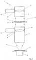
- FIG. 1a projection exposure apparatus 1 for microlithography is shown. This is used for exposure of structures on photosensitive materials coated substrate, which generally consists mainly of silicon and is referred to as wafer 2, for the production of semiconductor devices, such as computer chips.
- photosensitive materials coated substratewhich generally consists mainly of silicon and is referred to as wafer 2
- semiconductor devicessuch as computer chips.
- the projection exposure apparatus 1consists essentially of a lighting system 3, a device 4 for recording and exact positioning of a mask provided with a lattice - like structure, a so - called reticle 5, through which the later structures on the wafer 2 are determined, means 6 for holding, moving and exact positioning of precisely this wafer 2 and an imaging device, namely a lithography objective or lens Projection lens 7 with a plurality of optical elements, such as lenses 8, the versions 9 and / or in Fig. 1 not shown manipulators are mounted in a housing 10 of the lithographic lens 7.
- the basic principle of operationprovides that the structures introduced into the reticle 5 are imaged in a reduced manner on the wafer 2.
- the wafer 2is correspondingly moved further, so that a plurality of individual fields, each with the structure predetermined by the reticle 5, are exposed on the same wafer 2.
- the illumination system 3provides a projection beam 11 required for imaging the reticle 5 on the wafer 2, for example light or similar electromagnetic radiation.
- the source of this radiationmay be a laser or the like.
- the radiationis transmitted in the illumination system 3 via a plurality of optical elements, e.g. Lenses 8 ', which are mounted on sockets 9' in the illumination system 3, shaped so that the projection beam 11 when hitting the reticle 5 has the desired properties in terms of diameter, polarization, coherence and the like.
- the lithography objective 7has a multiplicity of individual refractive, diffractive and / or reflective optical elements, such as, for example, lenses 8, Mirrors, prisms, plane parallel plates and the like, wherein in Fig. 1 only the lens 8 is shown.
- optical elementssuch as the lenses 8 within the lithography objective 7 change over time, for example due to contamination or material changes, and the performance of the lithographic objective 7 deteriorates so that the desired lifetime of the same can not be achieved, they should be interchangeable in particular, the aberrations of others in Fig. 1 To compensate for not shown optical elements.
- an exchangemay also be necessary during operation in order, for example, to perform a double exposure of one area on the wafer 2 with two different reticles 5 or if different polarizations are to be used. Of course, such an exchange must be highly accurate, at least semi-automated and very quickly feasible.
- replacement of the lens 8 'may also be desirable in the lighting system 3.
- the positional tolerances for the tilt setting or the tilt (rotation about rx, ry, rz) and for the axial and lateral displacement (FIG. z, x, y)are in the range of less than 10 nm. Such accuracies can not be achieved with shims.
- Fig. 1For example, the optical elements 8, 8 'are designed to be exchangeable according to the invention with greatly simplified replacements 12, 12' of such high accuracy.
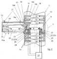
- Fig. 2the lithographic lens 7 is shown with a plurality of arranged in the housing 10 optical elements 13, which are arranged in sockets 14.
- the replaceable optical element 8is arranged deformation-decoupled in the version 9.
- the arrangement of the optical elements 13 within the lithography objective 7is to be regarded as purely exemplary.
- the lithographic objective 7may be suitable for any type of lithography. In the case of the lithographic objective 7, as described below, it is possible to exchange the optical element 8, which is mounted directly or via the mount, for example, preferably statically, in the lithographic objective 7.
- the replacement device 12is provided for replacing the optical element 8 in its version 9, which has a housing 15 with a gas-tight lid 15a, which is connected via a gas-tight coupling 16 with the housing 10 of the lithographic objective 7.
- the replacement device 12is mounted with sufficient rigidity on the housing 10 and remains there.
- the housing 10 of the lithographic objective 7has a lateral opening 17.
- the exchange device 12has a receptacle 18 for the optical element 8 in its version 9.
- the receptacle 18is motorally retractable through the lateral opening 17 of the housing 10 of the lithographic objective 7 by means of a drive device, not shown, and a guide device 19.
- a lifting device 18a, a device 18b for fixing the holder 9 of the optical element 8 to the lifting device 18a, a device 18c for guiding the lifting movement and a device 18d for moving the lifting device, which is guided in the guide device 19,are provided.
- the position of the optical element 8 in the exchange device 12, ie outside the lithography objective 7,is indicated by the reference numeral 20 in dashed lines.
- a coupling of the housing 15 of the exchange device 12 over controlled flow conditions to avoid contamination of the lithographic lens 7is also conceivable, ie, the pressure inside the housing 10 must be greater than outside the housing 10, so that a directed flow from the inside out.
- the exchanger 12may be purged with a high purity inert gas through inlet and outlet ports 21.
- the replaceable optical element 8 in its version 9is in the lithography objective 7 held on a separate support structure 22.
- the separate holding structurehas a manipulator device 22a with a plurality of actuators, not shown, for adjusting the exchangeable optical element 8 in, for example, preferably six degrees of freedom. In further embodiments, a smaller number of degrees of freedom may be adjustable.
- the socket 9 of the exchangeable optical element 8is introduced for fixing the separate holding structure 22 in a clamping device 23 designed as a fixing device.
- the clamping device 23is in FIG. 2 only very simplified, a closer look is off FIG. 3 seen.
- the separate support structure 22has for example for isostatic storage three runs with interfaces 22b (see FIG.
- the separate support structure 22is held on a rigid base mount 24, which is connected to the housing 10 of the lithography objective 7.
- the separate support structure 22is uniquely determined relative to the lithographic objective.
- the clamping device 23 remaining in the lithographic objective 7has a spring element 23a which fixes the socket 9 of the optical element 8.
- the clamping forcescan be adjusted manually or automatically.
- spacer washers 25are provided for rough pre-positioning of the replaceable optical element 8 and the socket 9, for example.
- adjustable contact surfaceswould also be conceivable here (not shown).
- the clamping device 23would be in the embodiment according to FIG.
- the fine positioning of the optical element 8 in the sockettakes place by the manipulator device 22a.
- a first sensor system 26is provided for determining the relative position and orientation of the exchangeable optical element 8 to the basic frame 24 or to other adjacent optical elements 13 or to a reference point or reference points.
- the exchangeable optical element 8has reference surfaces not shown. The fine positioning of the exchangeable optical element 8 takes place with the data of the first sensor system 26 by the manipulator device 22a from a first control system 27.
- An unillustrated arranged in the region of the receptacle 18 second sensor systemdetects the position and orientation of the replaceable optical element 8 during the exchange process, a likewise not shown second control system is provided which controls the guidance and the drive of the receptacle 18 based on the second sensor system monitored position and orientation of the interchangeable optical element 8 controlled.
- the replaceable optical element 8 or the mount 9are preferably stored statically within the lithography objective 7.
- the coarse pre-positioningtakes place approximately up to an alignment accuracy of the optical element 8 of up to 1 ⁇ m.
- the following alignment with high accuracyachieves positioning accuracies of less than 10 nm.
- FIG. 4is a further embodiment of a lithographic lens 7 'with a housing 10' shown in simplified.
- a plurality of optical elements 13are mounted in sockets 14 in the lithographic objective 7 '.
- a replaceable optical element 8is arranged in a mount 9" on a base mount 14 '.
- a replacement device 12“comprises a separate feed device 28 with a first receptacle 29 for a replaceable optical element 8a" to be supplied lateral opening 17 'in the housing 10' of the lithographic lens 7 'in the same is retractable and a separate removal device 30 with a second receptacle 31 for the removable exchangeable optical element 8b'', which through a second lateral opening 17 "in the housing 10th 'of the lithographic lens 7' in the same is retractable.
- a replaceable optical element 8 "to be removedcan be removed by the unloading device 30 and synchronously fed to a replaceable optical element 8a" through the feeder 28.
- the feeder 28has, for example, a memory 28a for storing the exchangeable optical elements 8a "to be supplied
- the removal device 30has, for example, a memory 30a for depositing the removed exchangeable optical elements 8b ".
- the exchangeable optical element 8 "is arranged in the vicinity, for example, of a pupil FIG. 4
- the optical element 8, 8 ', 8may be, for example, a diaphragm, a lens, a mirror, a beam splitter cube, a refractive or diffractive optical element or a group of said elements.
- the fifth stepmay be omitted if a rough pre-positioning of the optical element with respect to the Imaging quality already gives good results.
- the manipulator unit 22a and its associated sensors 26 and the control device 27can then be dispensed with.
- the exchange devicecan also be designed as a rotary carousel or the like.
Landscapes
- Physics & Mathematics (AREA)
- General Physics & Mathematics (AREA)
- Health & Medical Sciences (AREA)
- Engineering & Computer Science (AREA)
- Environmental & Geological Engineering (AREA)
- Epidemiology (AREA)
- Public Health (AREA)
- Exposure And Positioning Against Photoresist Photosensitive Materials (AREA)
- Exposure Of Semiconductors, Excluding Electron Or Ion Beam Exposure (AREA)
Description
Translated fromGermanDie Erfindung betrifft eine Austauschvorrichtung für wenigstens ein in einer lithographischen Projektionsbelichtungsanlage zumindest mittelbar gelagertes austauschbares optisches Element. Die Erfindung betrifft weiterhin ein Lithographieobjektiv und ein Beleuchtungssystem. Darüber hinaus betrifft die Erfindung ein Verfahren zur Positionierung eines austauschbaren optischen Elements innerhalb einer derartigen lithographischen Projektionsbelichtungsanlage und ein Verfahren zum Austauschen eines austauschbaren optischen Elements innerhalb einer lithographischen Projektionsbelichtungsanlage mittels einer Austauschvorrichtung.The invention relates to an exchange device for at least one interchangeable optical element mounted at least indirectly in a lithographic projection exposure apparatus. The invention further relates to a lithographic objective and a lighting system. Moreover, the invention relates to a method for positioning a replaceable optical element within such a lithographic projection exposure apparatus and a method for exchanging a replaceable optical element within a lithographic projection exposure apparatus by means of a replacement device.
Es sind Lithographieobjektive bekannt, bei denen das letzte optische Element, also dasjenige, das dem zu belichtenden Wafer am nächsten liegt, austauschbar ist.There are lithography lenses are known in which the last optical element, that is, which is closest to the wafer to be exposed, is interchangeable.
Bezüglich des die Erfindung betreffenden Standes der Technik wird auf die
Die
Wenn sich die optischen Elemente, wie beispielsweise Linsen oder Spiegel, innerhalb eines Lithographieobjektivs als Anlagenteil einer Projektionsbelichtungsanlage im Laufe der Zeit verändern, z.B. durch Kontaminationen oder Materialveränderungen, und sich die Leistung des Objektivs derart verschlechtert, dass die angestrebte Lebensdauer desselben nicht erreicht werden kann, so sollte es, insbesondere im Einsatzbereich mit möglichst geringem Aufwand möglich sein, ein entsprechend ausgewähltes optisches Element innerhalb des Objektivs zu entfernen und dafür ein neues, entsprechend bearbeitetes optisches Element einzusetzen, welches insbesondere auch die Abbildungsfehler der anderen optischen Elemente ausgleichen kann.If the optical elements, such as lenses or mirrors, within a lithographic lens as part of a projection exposure system change over time, for example due to contamination or material changes, and the performance of the lens deteriorates so that the desired lifetime of the same can not be achieved, so it should, especially in the field of application with the lowest possible Effort be possible to remove a correspondingly selected optical element within the lens and for a new, appropriately processed optical element to use, which can compensate especially the aberrations of the other optical elements.
Solange es sich bei den auszutauschenden optischen Elementen um Planparallelplatten oder um optische Elemente mit geringer Brechkraft handelt, sind bei einem Tausch neben hohen Anforderungen hinsichtlich Deformationen im Wesentlichen enge Toleranzen für Kippeinstellung und Z-Position, d.h. Position entlang der optischen Achse einzuhalten. Die laterale Verschiebung senkrecht zur optischen Achse spielt hierbei eine eher untergeordnete Rolle. Mit zunehmender Brechkraft bzw. zunehmender Sensitivität gegenüber Dezentrierungen gewinnt aber auch die laterale Verschiebung (Zentrierung zur optischen Achse) an Bedeutung.As long as the optical elements to be replaced are plane parallel plates or low refractive power optical elements, in addition to high deformation requirements, when exchanged, there are substantially close tolerances for tilt setting and Z position, i. Position along the optical axis. The lateral displacement perpendicular to the optical axis plays a rather minor role here. With increasing refractive power or increasing sensitivity to decentration but also the lateral displacement (centering to the optical axis) gains in importance.
Problematisch sind hauptsächlich Fertigungstoleranzen beim Austausch. Typischerweise kommen zum Ausgleich derartiger Fertigungstoleranzen auf Maß geschliffene Abstimmscheiben bzw. Abstandscheiben bzw. Spacer zum Einsatz. Dies erfordert jedoch eine aufwendige Logistik und Dokumentation, da die genauen Einbauzustände jedes potentiell auszutauschenden optischen Elements erfasst und archiviert werden müssen. Der Satz Abstandscheiben (z.B. sechs Abstandscheiben für eine Einstellung in sechs Freiheitsgraden) des neu einzubauenden optischen Elements muss abhängig von den vorhandenen Fertigungstoleranzen gefertigt und dem auszutauschenden optischen Element fest zugeordnet werden.The main problems are manufacturing tolerances during replacement. Typically, to compensate for such manufacturing tolerances on tailored ground Abstimmscheiben or spacers or spacers are used. However, this requires a complex logistics and documentation, since the exact installation states of each potentially exchangeable optical element must be recorded and archived. The set of shims (e.g., six shims for six degrees of freedom adjustment) of the new optical element to be installed must be fabricated depending on the existing manufacturing tolerances and dedicated to the optical element to be replaced.
Werden aufgrund der höheren Anforderungen für höher auflösende optische Systeme die Toleranzen für die Position nach einem derartigen Austausch so gering, dass ein Ausgleich der mechanischen Fertigungstoleranzen durch Abstandscheiben nicht mehr möglich ist, so muss eine andere Lösung für die Einhaltung der Positionstoleranzen nach einem Tausch gefunden werden. Diese Grenze ist beispielsweise dann erreicht, wenn Abstandscheiben mit einer Genauigkeit von < 1µm bis weit in den Sub-µm-Bereich hinein auf Maß geschliffen werden sollten.If due to the higher requirements for higher resolution optical systems, the tolerances for the position after such an exchange so small that a balance of mechanical manufacturing tolerances is no longer possible by spacers, so another solution for compliance with the position tolerances after replacement must be found , This limit is achieved, for example, when spacers with an accuracy of <1μ m extend far into the sub-μ m range Dimension should be ground.
Wenn die auszutauschenden optischen Elemente z.B. Linsen mit entsprechender Brechkraft sind, können die Positionstoleranzen für die Kippeinstellung bzw. die Verkippung (Rotation um rx, ry, rz) sowie für die axiale und die laterale Verschiebung (x, y, z) im Bereich weniger 10 nm liegen. In diesem Fall sind die konventionellen Konzepte mit Abstandsscheiben nicht ausreichend, da derartige Genauigkeiten nicht mehr erreicht werden können.If the optical elements to be exchanged, e.g. Lenses are with appropriate refractive power, the position tolerances for the tilt setting or tilting (rotation by rx, ry, rz) and for the axial and the lateral displacement (x, y, z) in the range less than 10 nm. In this case, the conventional concepts with shims are not sufficient because such accuracies can not be achieved.
Es ist daher Aufgabe der vorliegenden Erfindung, eine Austauschvorrichtung für ein in einer lithographischen Projektionsbelichtungsanlage zumindest mittelbar gelagertes optisches Element zu schaffen, die einen derartigen Austausch mit hohen Genauigkeiten ermöglicht.It is therefore the object of the present invention to provide an exchange device for an optical element which is at least indirectly mounted in a lithographic projection exposure apparatus and which permits such an exchange with high accuracies.
Gemäß der Erfindung ist hierzu eine Austauschvorrichtung für wenigstens ein in einer lithographischen Projektionsbelichtungsanlage zumindest mittelbar gelagertes in einer Fassung angeordnetes austauschbares optisches Element vorgesehen, mit wenigstens einer Aufnahme für das austauschbare optische Element, welche durch wenigstens eine Öffnung in einem Gehäuse eines Anlagenteils der lithographischen Projektionsbelichtungsanlage in dasselbe einbringbar ist, wobei das austauschbare optische Element in dem Anlagenteil auf einer separaten Haltestruktur gehalten ist, wobei das austauschbare optische Element zur Fixierung auf der separaten Haltestruktur mittels der Fassung in eine entsprechend hinreichend steif ausgeführte Klemmeinrichtung eingebracht ist, deren Wirkkräfte im Wesentlichen nicht auf die separate Haltestruktur wirken bzw. wodurch die separate Haltestruktur von den Klemmkräften der Klemmeinrichtung wenigstens annähernd entkoppelt ist. Dadurch ist das Positionierungssystem von dem Fixierungssystem des optischen Elements in vorteilhafter Weise entkoppelt.According to the invention, an exchange device is provided for this purpose for at least one interchangeable optical element mounted at least indirectly in a lithographic projection exposure apparatus, with at least one receptacle for the replaceable optical element, which is penetrated through at least one opening in a housing of an installation part of the lithographic projection exposure apparatus the same is introduced, wherein the replaceable optical element is held in the plant part on a separate support structure, wherein the interchangeable optical element for fixing on the separate support structure is inserted by means of the socket in a suitably stiff executed clamping device whose forces substantially not on the act separate holding structure or whereby the separate support structure is at least approximately decoupled from the clamping forces of the clamping device. As a result, the positioning system is decoupled from the fixing system of the optical element in an advantageous manner.
Diese Austauschvorrichtung ist in der Lage, das optische Element aus dem Anlagenteil zu entnehmen und ein anderes, speziell auf die Veränderungen innerhalb des Anlagenteils abgestimmtes optisches Element wieder in den Anlagenteil einzufahren bzw. zuzuführen. Es ist lediglich wenigstens eine Öffnung in dem Gehäuse des Anlagenteils erforderlich, welche so bemessen ist, dass die Aufnahme in das Gehäuse einfahren kann. Hierbei ist die Aufnahme in der Lage, das optische Element sehr genau innerhalb des Anlagenteils zu positionieren. Das austauschbare optische Element ist in dem Anlagenteil auf einer separaten Haltestruktur gehalten. Zur Fixierung auf der separaten Haltestruktur ist das austauschbare optische Element in eine Fixierungseinrichtung eingebracht. In vorteilhafter Weise wirken die Wirkkräfte der Fixierungseinrichtung nicht auf die separate Haltestruktur. Dadurch werden parasitäre Einflüsse auf die angrenzenden Komponenten minimiert. Der Kraftschluss wird lokal und nicht über die separate Haltestruktur geführt, sodass diese auch als Manipulatoreinrichtung zur Feinpositionierung eingesetzt werden kann.This exchange device is able to remove the optical element from the plant part and another, especially on to retract or supply the changes within the plant part tuned optical element back into the plant part. It is only required at least one opening in the housing of the plant part, which is dimensioned so that the receptacle can retract into the housing. In this case, the recording is able to position the optical element very accurately within the plant part. The replaceable optical element is held in the plant part on a separate support structure. For fixing on the separate support structure, the exchangeable optical element is introduced into a fixing device. Advantageously, the effective forces of the fixing device do not affect the separate holding structure. This minimizes parasitic influences on the adjacent components. The adhesion is performed locally and not on the separate support structure, so that it can also be used as a manipulator device for fine positioning.
Vorteilhaft ist, wenn der Anlagenteil ein Lithographieobjektiv und/oder ein Beleuchtungssystem oder Teile davon umfasst.It is advantageous if the plant part comprises a lithography lens and / or a lighting system or parts thereof.
Hierdurch lässt sich etwa die Abbildungsleistung des Lithographieobjektivs erheblich verbessern, ohne dass in die Struktur des Lithographieobjektivs eingegriffen wird.As a result, it is possible, for example, to considerably improve the imaging performance of the lithographic objective without interfering with the structure of the lithographic objective.
Erfindungsgemäß kann ferner vorgesehen sein, dass die wenigstens eine Aufnahme mittels einer Antriebseinrichtung und einer Führungseinrichtung motorisch einfahrbar ist.According to the invention, it can further be provided that the at least one receptacle can be retracted by means of a drive device and a guide device.
Dadurch kann auch ein wenigstens teilautomatisierter Austausch erfolgen, um beispielsweise während des Betriebs des Lithographieobjektivs eine doppelte Belichtung eines Bereiches eines Substrats mit zwei unterschiedlichen Reticles durchführen zu können.As a result, it is also possible to carry out an at least partially automated exchange in order, for example, to be able to perform a double exposure of a region of a substrate with two different reticles during the operation of the lithographic objective.
Das optische Element ist in vorteilhafter Weise in einer Fassung bzw. Wechselfassung angeordnet. Um Deformationen auf das optische Element zu vermeiden kann die Fassung im Bereich der Fixierungseinrichtung von Momenten der separaten Haltestruktur und/oder der Fixierungseinrichtung entkoppelt sein.The optical element is advantageously arranged in a socket or exchange fitting. In order to avoid deformations on the optical element, the socket in the region of the fixing device be decoupled from moments of the separate support structure and / or the fixing device.
Vorteilhaft ist, wenn das austauschbare optische Element Referenzflächen zur Erfassung der Position und Orientierung desselben aufweist. Dadurch kann in vorteilhafter Weise sowohl beim Austauschvorgang als auch bei einer endgültigen Feinpositionierung des austauschbaren optischen Elements in dem Anlagenteil bzw. dem Lithographieobjektiv anhand der Referenzflächen eine genaue Position und Orientierung des austauschbaren optischen Elements bestimmt werden.It is advantageous if the exchangeable optical element has reference surfaces for detecting the position and orientation thereof. As a result, an exact position and orientation of the exchangeable optical element can advantageously be determined both during the replacement process and during a final fine positioning of the exchangeable optical element in the plant part or the lithographic objective based on the reference surfaces.
Zur groben Vorpositionierung des austauschbaren optischen Elements innerhalb des Anlagenteils auf der separaten Haltestruktur können Abstandsscheiben bzw. Abstimmscheiben bzw. Spacer vorgesehnen sein. Darüber sind auch einstellbare Anlageflächen denkbar.For coarse prepositioning of the replaceable optical element within the equipment part on the separate support structure, spacer disks or spacers may be provided. In addition, adjustable contact surfaces are conceivable.
In einer besonders vorteilhaften konstruktiven Ausgestaltung der Erfindung kann ferner vorgesehen sein, dass die separate Haltestruktur eine Manipulatoreinrichtung mit wenigstens einem Aktuator zur Einstellung des austauschbaren optischen Elements in wenigstens einem, insbesondere in sechs Freiheitsgraden aufweist.In a particularly advantageous structural embodiment of the invention may also be provided that the separate support structure has a manipulator device with at least one actuator for adjusting the replaceable optical element in at least one, in particular in six degrees of freedom.
Durch diese Maßnahmen kann das in die Fixierungseinrichtung bzw. Klemmeinrichtung eingebrachte, austauschbare optische Element in mehreren, insbesondere in sechs Freiheitsgraden einjustiert werden. Ein erstes Sensorsystem kann dazu zur Ermittlung der relativen Position und Orientierung des austauschbaren Elements zu dem Anlagenteil auf der separaten Haltestruktur vorgesehen sein. Die Feinpositionierung insbesondere im Bereich weniger 10 Nanometer des austauschbaren optischen Elements erfolgt hiernach mit den Daten des ersten Sensorsystems durch die Manipulatoreinrichtung und wird von einem ersten Steuerungssystem mittels eines geschlossenen Regelkreises geregelt.As a result of these measures, the exchangeable optical element introduced into the fixing device or clamping device can be adjusted in several, in particular in six degrees of freedom. A first sensor system may be provided for determining the relative position and orientation of the replaceable element to the plant part on the separate support structure. The fine positioning, in particular in the range of less than 10 nanometers of the exchangeable optical element, is hereafter carried out with the data of the first sensor system by the manipulator device and is controlled by a first control system by means of a closed control loop.
Vorteilhaft ist es, wenn das austauschbare optische Element oder die Fassung in der das austauschbare optische Element angeordnet ist, innerhalb des Anlagenteils statisch bestimmt gelagert ist.It is advantageous if the replaceable optical element or the socket in which the replaceable optical element is arranged, is stored statically determined within the plant part.
Erfindungsgemäß kann ferner vorgesehen sein, dass eine separate Zuführeinrichtung mit einer ersten Aufnahme für ein zuzuführendes austauschbares optisches Element, welche durch wenigstens eine erste seitliche Öffnung in dem Gehäuse des Anlagenteils in dasselbe einfahrbar ist, vorgesehen ist und dass eine separate Entnahmeeinrichtung mit einer zweiten Aufnahme für das zu entnehmende austauschbare optische Element, welche durch wenigstens eine zweite seitliche Öffnung in dem Gehäuse des Anlagenteils in dasselbe einfahrbar ist, vorgesehen ist.According to the invention, it can further be provided that a separate feed device is provided with a first receptacle for a replaceable optical element to be fed, which can be inserted into the housing of the system part through at least one first lateral opening, and a separate extraction device with a second receptacle for the interchangeable optical element to be removed, which can be introduced into the housing of the system component by at least one second lateral opening, is provided.
Dadurch kann synchron und teilautomatisiert das zu entfernende austauschbare Element durch die Entnahmeeinrichtung entnommen und das zuzuführende austauschbare optische Element durch die Zuführeinrichtung zugeführt werden.As a result, the replaceable element to be removed can be removed synchronously and semi-automatically by the removal device and the replaceable optical element to be supplied can be supplied by the supply device.
Vorteilhaft ist es, wenn wenigstens die Zuführeinrichtung oder die Entnahmeeinrichtung einen Speicher zur Ablage der zuzuführenden oder entnommenen austauschbaren optischen Elemente aufweisen.It is advantageous if at least the feed device or the removal device has a memory for depositing the exchangeable optical elements to be supplied or removed.
Ein Lithographieobjektiv mit mehreren optischen Elementen und mit wenigstens einer erfindungsgemäßen Austauschvorrichtung ist in Anspruch 20 angegeben.A lithographic objective with a plurality of optical elements and with at least one inventive exchange device is specified in
Des weiteren wird ein Beleuchtungssystem für die Mikrolithographie mit einer erfindungsgemäßen Austauschvorrichtung in Anspruch 21 vorgeschlagen.Furthermore, a lighting system for microlithography with an inventive exchange device is proposed in
In Anspruch 23 ist ein Verfahren zur Positionierung eines austauschbaren optischen Elements innerhalb eines Lithographieobjektivs mittels einer erfindungsgemäßen Austauschvorrichtung beschrieben.
Des weiteren ist ein Verfahren zum austauschen eines austauschbaren optischen Elements innerhalb eines Lithographieobjektivs mittels einer erfindungsgemäßen Austauschvorrichtung in Anspruch 24 angegeben.Furthermore, a method for exchanging a replaceable optical element within a lithography objective by means of a replacement device according to the invention is specified in
Weitere vorteilhafte Ausgestaltungen und Weiterbildungen ergeben sich aus den restlichen Unteransprüchen. Nachstehend sind verschiedene Ausführungsbeispiele der Erfindung anhand der Zeichnung prinzipmäßig dargestellt.Further advantageous embodiments and developments emerge from the remaining subclaims. Below, various embodiments of the invention with reference to the drawings are shown in principle.
Es zeigt:
Figur 1- eine Prinzipdarstellung einer Projektionsbelichtungsanlage für die Mikrolithographie, welche zur Belichtung von Strukturen auf mit photosensitiven Materialien beschichtete Wafer verwendbar ist;
Figur 2- eine Schnittansicht eines Lithographieobjektivs mit mehreren optischen Elementen und einer erfindungsgemäßen Austauschvorrichtung;
Figur 3- eine Ausschnittsvergrößerung des Ausschnitts Z aus
Figur 2; und Figur 4- eine Schnittansicht eines Lithographieobjektivs mit mehreren optischen Elementen und einer Austauschvorrichtung in einer weiteren Ausführungsform.
- FIG. 1
- a schematic representation of a projection exposure apparatus for microlithography, which is used for the exposure of structures on photosensitive materials coated wafers;
- FIG. 2
- a sectional view of a lithographic objective with a plurality of optical elements and a replacement device according to the invention;
- FIG. 3
- an enlarged detail of the detail Z of Figure 2; and
- FIG. 4
- a sectional view of a lithographic lens with a plurality of optical elements and a replacement device in another embodiment.
In
Die Projektionsbelichtungsanlage 1 besteht dabei im wesentlichen aus einem Beleuchtungssystem 3, einer Einrichtung 4 zur Aufnahme und exakten Positionierung einer mit einer gitterartigen Struktur versehenen Maske, einem sogenannten Reticle 5, durch welches die späteren Strukturen auf dem Wafer 2 bestimmt werden, einer Einrichtung 6 zur Halterung, Bewegung und exakten Positionierung eben dieses Wafers 2 und einer Abbildungseinrichtung, nämlich einem Lithographieobjektiv bzw. Projektionsobjektiv 7 mit mehreren optischen Elementen, wie z.B. Linsen 8, die über Fassungen 9 und/oder in
Das grundsätzliche Funktionsprinzip sieht dabei vor, dass die in das Reticle 5 eingebrachten Strukturen auf den Wafer 2 verkleinert abgebildet werden.The basic principle of operation provides that the structures introduced into the
Nach einer erfolgten Belichtung wird der Wafer 2 entsprechend weiterbewegt, sodass auf demselben Wafer 2 eine Vielzahl von einzelnen Feldern, jeweils mit der durch das Reticle 5 vorgegebenen Struktur, belichtet werden.After a successful exposure, the
Das Beleuchtungssystem 3 stellt einen für die Abbildung des Reticles 5 auf dem Wafer 2 benötigten Projektionsstrahl 11, beispielsweise Licht oder eine ähnliche elektromagnetische Strahlung, bereit. Als Quelle für diese Strahlung kann ein Laser oder dergleichen Verwendung finden. Die Strahlung wird in dem Beleuchtungssystem 3 über mehrere optische Elemente wie z.B. Linsen 8', die über Fassungen 9' in dem Beleuchtungssystem 3 gelagert sind, so geformt, dass der Projektionsstrahl 11 beim Auftreffen auf das Reticle 5 die gewünschten Eigenschaften hinsichtlich Durchmesser, Polarisation, Kohärenz und dergleichen aufweist.The
Über den Projektionsstrahl 11 wird ein Bild der eingebrachten Strukturen des Reticles 5 erzeugt und von dem Lithographieobjektiv 7 entsprechend verkleinert auf den Wafer 2 übertragen, wie bereits vorstehend erläutert wurde. Das Lithographieobjektiv 7 weist eine Vielzahl von einzelnen refraktiven, diffraktiven und/oder reflektiven optischen Elementen, wie z.B. Linsen 8, Spiegeln, Prismen, Planparallelplatten und dergleichen auf, wobei in
Wenn sich die optischen Elemente, wie beispielsweise die Linsen 8 innerhalb des Lithographieobjektivs 7 im Laufe der Zeit verändern, z.B. durch Kontaminationen oder Materialveränderungen, und sich die Leistung des Lithographieobjektivs 7 derart verschlechtert, dass die angestrebte Lebensdauer desselben nicht erreicht werden kann, sollten diese austauschbar sein, um insbesondere auch die Abbildungsfehler der anderen in
Falls es sich bei den auszutauschenden optischen Elementen, wie vorliegend um Linsen 8, 8' mit entsprechender Brechkraft handelt, können die Positionstoleranzen für die Kippeinstellung bzw. die Verkippung (Rotation um rx, ry, rz) sowie für die axiale und die laterale Verschiebung (z, x, y) im Bereich weniger 10 nm liegen. Derartige Genauigkeiten können mit Abstandsscheiben nicht mehr erreicht werden.If the optical elements to be exchanged, such as
In
In
Wie weiter aus
In einer Ausführung der Klemmvorrichtung nach
Ein nicht dargestelltes im Bereich der Aufnahme 18 angeordnetes zweites Sensorsystem ermittelt die Position und die Orientierung des austauschbaren optischen Elements 8 während des Austauschvorgangs, wobei ein ebenfalls nicht dargestelltes zweites Steuerungssystem vorgesehen ist, welches die Führung und den Antrieb der Aufnahme 18 basierend auf der von dem zweiten Sensorsystem überwachten Position und Orientierung des austauschbaren optischen Elements 8 kontrolliert. Das austauschbare optische Element 8 bzw. die Fassung 9 sind innerhalb des Lithographieobjektiv 7 vorzugsweise statisch bestimmt gelagert.An unillustrated arranged in the region of the
Ein Verfahren zur Positionierung des austauschbaren optischen Elements 8 innerhalb des Lithographieobjektivs 7 mittels der Austauschvorrichtung 12 läuft dabei wie folgt ab:
- in einem ersten Schritt wird das austauschbare optische
Element 8 auf die separate Haltestruktur 22, welche die Manipulatoreinrichtung 22a aufweist, abgelegt, wonach - in einem zweiten Schritt das austauschbare optische
Element 8 relativ zu der separaten Haltestruktur 22 grob vorpositioniert und mittels der Klemmeinrichtung 23 fixiert wird und wonach - in einem dritten Schritt das austauschbare optische
Element 8 mittels der Manipulatoreinrichtung 22a relativ zudem Gehäuse 10 desLithographieobjektivs 7 mit hoher Genauigkeit ausgerichtet wird.
- In a first step, the exchangeable
optical element 8 is deposited on the separate holding structure 22, which has the manipulator device 22a, after which - in a second step, the replaceable
optical element 8 is roughly prepositioned relative to the separate support structure 22 and fixed by means of theclamping device 23 and according to what - in a third step, the replaceable
optical element 8 is aligned by means of the manipulator device 22a relative to thehousing 10 of thelithographic objective 7 with high accuracy.
Die grobe Vorpositionierung erfolgt dabei etwa bis zu einer Ausrichtungsgenauigkeit des optischen Elements 8 von bis zu 1µm. Die folgende Ausrichtung mit hoher Genauigkeit erreicht Positioniergenauigkeiten von kleiner 10 nm.The coarse pre-positioning takes place approximately up to an alignment accuracy of the
In
Im vorliegenden Ausführungsbeispiel ist das austauschbare optische Element 8" in der Nähe z.B. einer Pupille angeordnet. In
Ein Verfahren zum Austauschen des austauschbaren optischen Elements 8" innerhalb des Lithographieobjektivs 7' mittels der Austauschvorrichtung 12" kann wie folgt durchgeführt werden:
- in einem ersten Schritt wird die durch die
Klemmeinrichtung 23 erfolgte Fixierung des zu entnehmenden austauschbaren optischen Elements 81" auf der die Manipulatoreinrichtung 22a aufweisenden separaten Haltestruktur 22 gelöst, wonach - in einem zweiten Schritt das zu entnehmende austauschbare optische
Element 8"von der Entnahmeeinrichtung 30 erfasst wird, wobei wenigstens annähernd gleichzeitig das zuzuführende austauschbare optischeElement 8a"von der Zuführeinrichtung 28 erfasst wird, wonach - in einem dritten Schritt eine wenigstens annähernd synchrone Bewegung durch die
Entnahmeeinrichtung 30 und dieZuführeinrichtung 28 erfolgt, wobei nahezu gleichzeitig das zu entnehmende optische Element 8'' aus dem Lithographieobjektiv 7' entnommen und das zuzuführende optischeElement 8a'' in das Lithographieobjektiv 7' eingeführt und auf der separaten Haltestruktur 22 abgelegt wird, wonach - in einem vierten Schritt das zuzuführende austauschbare optische
Element 8a" relativ zu der separaten Haltestruktur 22 grob vorpositioniert und mittels der Klemmeinrichtung 23 fixiert wird, und wonach - in einem fünften Schritt das zuzuführende austauschbare optische
Element 8a" mittels der Manipulatoreinrichtung 22a relativ zu dem Gehäuse 10' des Lithographieobjektivs 7' mit hoher Genauigkeit ausgerichtet wird.
- In a first step, the fixation of the interchangeable optical element 81 "to be removed by the clamping
device 23 is released on the separate holding structure 22 having the manipulator device 22a, whereupon - in a second step, the exchangeable
optical element 8 "to be removed is detected by theremoval device 30, wherein the replaceableoptical element 8a" to be supplied is detected by thesupply device 28 at least approximately simultaneously, after which - in a third step, at least approximately synchronous movement by the
removal device 30 and thefeeder 28 takes place, wherein almost simultaneously removed the optical element to be removed 8 '' from the lithographic lens 7 'and the suppliedoptical element 8a''introduced into the lithographic lens 7' and deposited on the separate support structure 22, after which - in a fourth step, the exchangeable
optical element 8a "to be supplied is roughly prepositioned relative to the separate support structure 22 and fixed by means of theclamping device 23, and then - in a fifth step, the exchangeable
optical element 8a "to be supplied is aligned with high accuracy by means of the manipulator device 22a relative to the housing 10 'of the lithographic objective 7'.
In bestimmten Fällen kann der fünfte Schritt entfallen, wenn eine grobe Vorpositionierung des optischen Elements bezüglich der Abbildungsqualität bereits gute Ergebnisse liefert. In solchen Fällen kann dann auch die Manipulatoreinheit 22a und deren zugeordnete Sensoren 26 sowie die Steuereinrichtung 27 entfallen.In certain cases, the fifth step may be omitted if a rough pre-positioning of the optical element with respect to the Imaging quality already gives good results. In such cases, the manipulator unit 22a and its associated
In einem weiteren nicht dargestellten Ausführungsbeispiel kann die Austauschvorrichtung auch als Drehkarussell oder dergleichen ausgeführt sein.In a further embodiment, not shown, the exchange device can also be designed as a rotary carousel or the like.
Claims (25)
- Replacement device (12, 12', 12") for at least one replaceable optical element (8, 8', 8", 8a", 8b") mounted at least indirectly in a lithographic projection exposure apparatus (1) and arranged in a mount (9, 9', 9"), comprising at least one receptacle (18) for the replaceable optical element (8, 8', 8", 8a", 8b"), which can be introduced into a housing (10, 10') of an apparatus part (7, 7', 3) of the projection exposure apparatus (1) through at least one opening (17, 17', 17") in said housing, wherein the replaceable optical element (8, 8', 8",8a", 8b") is held in the apparatus part (7) on a separate holding structure(22),characterized in that the replaceable optical element (8, 8', 8", 8a", 8b") is introduced into a correspondingly sufficiently rigidly designed clamping device (23) for fixing on the separate holding structure (22) by means of the mount (9, 9', 9"), whereby the separate holding structure (22) is at least approximately decoupled from the clamping forces of the clamping device (23).
- Replacement device according to Claim 1, wherein the apparatus part comprises a lithography objective (7, 7') and/or an illumination system (3) or parts thereof.
- Replacement device according to Claim 2, wherein the opening (17, 17', 17") is a lateral opening relative to the direction of a projection beam (11) of the projection exposure apparatus (1).
- Replacement device according to Claim 1, wherein the at least one receptacle (18) can be retracted motively by means of a drive device and a guide device (19).
- Replacement device according to Claim 1, wherein the mount (9) is decoupled from moments of the separate holding structure (22) and/or of the clamping device (23) in the region of the clamping device (23).
- Replacement device according to Claim 1, wherein the separate holding structure (22) is determined unambiguously relative to the apparatus part (7, 7', 3).
- Replacement device according to Claim 1, wherein the separate holding structure is held in a basic mount (24) connected to the housing (10, 10') of the apparatus part (7, 7', 3).
- Replacement device according to Claim 1, wherein the replaceable optical element (8, 8', 8", 8a", 8b") has reference surfaces for detecting the position and orientation thereof.
- Replacement device according to Claim 1, wherein spacer washers (25) are provided for the coarse prepositioning of the replaceable optical element on the separate holding structure(22).
- Replacement device according to Claim 1, wherein the separate holding structure (22) has a manipulator device (22a) with at least one actuator for setting the replaceable optical element (8) in at least one, in particular in six, degrees of freedom.
- Replacement device according to Claim 1, wherein a first sensor system (26) is provided for determining the relative position and orientation of the replaceable optical element (8) with respect to the apparatus part (7, 7', 3) on the separate holding structure (22).
- Replacement device according to Claim 11, wherein a fine positioning of the replaceable optical element (8) can be carried out by means of the manipulator device (22a).
- Replacement device according to Claims 11 and 12, wherein the fine positioning of the replaceable optical element (8) can be carried out by a first control system (27) using the data of the first sensor system (26) by means of the manipulator device (22a).
- Replacement device according to Claim 1, wherein at least one second sensor system is provided which determines the position and the orientation of the replaceable optical element (8) during the replacement operation in the course of supply and in the course of removal.
- Replacement device according to Claim 14, wherein at least one second control system is provided which controls the guidance and the drive of the movement of the at least one receptacle (18) based on the position and orientation of the replaceable optical element (8) monitored by the at least one second sensor system in the course of supply and in the course of removal of the replaceable optical element (8).
- Replacement device according to Claim 1, wherein a separate supply device (28) with a first receptacle (29) for a replaceable optical element (8", 8a", 8b") to be supplied, which can be retracted into the housing (10') of the apparatus part (7') through at least one first lateral opening (17') in said housing, is provided.
- Replacement device according to Claim 16, wherein a separate removal device (30) with a second receptacle (31) for the replaceable optical element (8", 8a", 8b") to be removed, which can be retracted into the housing (10') of the apparatus part (7') through at least one second lateral opening(17"), is provided.
- Replacement device according to Claim 17, wherein the replaceable optical element (8") to be removed can be removed by the removal device (30) and the replaceable optical element (8a") to be supplied can be supplied by the supply device (28), synchronously.
- Replacement device according to Claim 16, wherein at least the supply device (28) or the removal device (30) has a store (28a, 30a) for depositing the replaceable optical elements (8", 8a", 8b") to be supplied or the replaceable optical elements (8", 8a", 8b"), that have been removed.
- Lithography objective (7, 7') comprising a plurality of optical elements (8, 8', 8", 8a", 8b", 13) and comprising at least one replacement device (12, 12', 12") according to Claim 1, wherein at least one of the optical elements (8, 8', 8", 8a", 8b") can be replaced by the at least one replacement device (12, 12', 12").
- Illumination system (3) for microlithography comprising a replacement device (12') according to Claim 1 for at least one replaceable optical element (8') mounted at least indirectly in the illumination system (3) as apparatus part of the projection exposure apparatus (1).
- Method for producing semiconductor components using a lithography objective (7, 7') according to Claim 20.
- Method for positioning a replaceable optical element (8) within a lithographic projection exposure apparatus (1) by means of a replacement device (12) according to Claim 1, wherein:- in a first step, the replaceable optical element (8) is deposited onto the separate holding structure (22), which has a manipulator device (22a), after which- in a second step, the replaceable optical element (8) is coarsely prepositioned relative to the separate holding structure (22) and fixed by means of the clamping device (23), after which- in a third step, the replaceable optical element (8) is finely positioned relative to the housing or a further optical element of the projection exposure apparatus (1) by means of the manipulator device (22a).
- Method for replacing a replaceable optical element (8") within a lithographic projection exposure apparatus (1) by means of a replacement device (12") according to Claim 17, wherein:- in a first step, the fixing - effected by the clamping device (23) - of the replaceable optical element (8") to be removed on the separate holding structure (22) having a manipulator device (22a) is released, after which- in a second step, the replaceable optical element (8") to be removed is picked up by the removal device (30), wherein, at least approximately simultaneously, the replaceable optical element (8a") to be supplied is picked up by the supply device (28), after which- in a third step, an at least approximately synchronous movement is effected by the removal device (30) and the supply device (28), wherein the optical element (8") to be removed is removed from the projection exposure apparatus (1) and the optical element (8a") to be supplied is introduced into the projection exposure apparatus (1) and deposited on the separate holding structure (22), after which- in a fourth step, the replaceable optical element (8a") to be supplied is coarsely prepositioned relative to the separate holding structure (22) and fixed by means of the clamping device (23).
- Method according to Claim 24, wherein, in a fifth step, the replaceable optical element (8a") to be supplied is finely positioned relative to the housing of the lithographic projection exposure apparatus (1) by means of the manipulator device (22a).
Applications Claiming Priority (2)
| Application Number | Priority Date | Filing Date | Title |
|---|---|---|---|
| US71068005P | 2005-08-23 | 2005-08-23 | |
| PCT/EP2006/008160WO2007022922A2 (en) | 2005-08-23 | 2006-08-18 | Replacement device for an optical element |
Publications (2)
| Publication Number | Publication Date |
|---|---|
| EP1922586A2 EP1922586A2 (en) | 2008-05-21 |
| EP1922586B1true EP1922586B1 (en) | 2016-05-11 |
Family
ID=37560848
Family Applications (1)
| Application Number | Title | Priority Date | Filing Date |
|---|---|---|---|
| EP06776955.4ANot-in-forceEP1922586B1 (en) | 2005-08-23 | 2006-08-18 | Replacement device for an optical element |
Country Status (3)
| Country | Link |
|---|---|
| US (1) | US8027024B2 (en) |
| EP (1) | EP1922586B1 (en) |
| WO (1) | WO2007022922A2 (en) |
Cited By (1)
| Publication number | Priority date | Publication date | Assignee | Title |
|---|---|---|---|---|
| WO2025031712A1 (en)* | 2023-08-09 | 2025-02-13 | Carl Zeiss Smt Gmbh | Optical system and projection exposure system |
Families Citing this family (8)
| Publication number | Priority date | Publication date | Assignee | Title |
|---|---|---|---|---|
| KR101235492B1 (en) | 2006-07-03 | 2013-02-20 | 칼 짜이스 에스엠테 게엠베하 | Lithography Projection Objective Correction / Repair Method |
| CN101548240B (en) | 2006-12-01 | 2014-09-17 | 卡尔蔡司Smt有限责任公司 | Optical system with an exchangeable, manipulable correction arrangement for reducing image aberrations |
| DE102007009867A1 (en)* | 2007-02-28 | 2008-09-11 | Carl Zeiss Smt Ag | Imaging device with interchangeable diaphragms and method for this |
| DE102008044365A1 (en) | 2007-12-18 | 2009-06-25 | Carl Zeiss Smt Ag | Projection exposure system for manufacturing semiconductor component i.e. computer chip, has changing unit for changing optical assembly that is exchangeably formed, and bearing unit reducing deformations of optical element caused by holder |
| DE102008032853A1 (en) | 2008-07-14 | 2010-01-21 | Carl Zeiss Smt Ag | Optical device with a deformable optical element |
| US10345703B2 (en) | 2014-11-26 | 2019-07-09 | Massachusetts Institute Of Technology | Systems, devices, and methods for printing on three-dimensional objects |
| DE102019214242A1 (en)* | 2019-09-18 | 2021-03-18 | Carl Zeiss Smt Gmbh | Projection exposure system for semiconductor lithography |
| DE102022214186A1 (en)* | 2022-12-21 | 2024-06-27 | Carl Zeiss Smt Gmbh | OPTICAL SYSTEM AND PROJECTION EXPOSURE SYSTEM |
Family Cites Families (9)
| Publication number | Priority date | Publication date | Assignee | Title |
|---|---|---|---|---|
| US5305054A (en) | 1991-02-22 | 1994-04-19 | Canon Kabushiki Kaisha | Imaging method for manufacture of microdevices |
| JP3278896B2 (en) | 1992-03-31 | 2002-04-30 | キヤノン株式会社 | Illumination apparatus and projection exposure apparatus using the same |
| JP4945845B2 (en)* | 2000-03-31 | 2012-06-06 | 株式会社ニコン | An optical element holding device, a lens barrel, an exposure apparatus, and a microdevice manufacturing method. |
| DE10121346A1 (en) | 2001-05-02 | 2002-11-07 | Zeiss Carl | Objective, in particular a projection objective for semiconductor lithography |
| JP3710443B2 (en)* | 2002-09-11 | 2005-10-26 | キヤノン株式会社 | Mirror holding device and method, and mirror replacement method |
| AU2003290094A1 (en) | 2003-10-29 | 2005-06-08 | Asml Netherlands B.V. | Optical assembly for photolithography |
| US7265917B2 (en)* | 2003-12-23 | 2007-09-04 | Carl Zeiss Smt Ag | Replacement apparatus for an optical element |
| US7296777B2 (en)* | 2004-03-24 | 2007-11-20 | Nikon Corporation | Acceleration clamp assist |
| US7724351B2 (en)* | 2006-01-30 | 2010-05-25 | Asml Netherlands B.V. | Lithographic apparatus, device manufacturing method and exchangeable optical element |
- 2006
- 2006-08-18EPEP06776955.4Apatent/EP1922586B1/ennot_activeNot-in-force
- 2006-08-18WOPCT/EP2006/008160patent/WO2007022922A2/enactiveApplication Filing
- 2008
- 2008-02-11USUS12/029,165patent/US8027024B2/enactiveActive
Cited By (1)
| Publication number | Priority date | Publication date | Assignee | Title |
|---|---|---|---|---|
| WO2025031712A1 (en)* | 2023-08-09 | 2025-02-13 | Carl Zeiss Smt Gmbh | Optical system and projection exposure system |
Also Published As
| Publication number | Publication date |
|---|---|
| US20080174758A1 (en) | 2008-07-24 |
| US8027024B2 (en) | 2011-09-27 |
| EP1922586A2 (en) | 2008-05-21 |
| WO2007022922A3 (en) | 2007-07-26 |
| WO2007022922A2 (en) | 2007-03-01 |
Similar Documents
| Publication | Publication Date | Title |
|---|---|---|
| EP1922586B1 (en) | Replacement device for an optical element | |
| WO2007085290A2 (en) | Method and device for the correction of imaging defects | |
| DE69023186T2 (en) | Exposure device. | |
| EP1456891B1 (en) | Imaging device in a projection exposure facility | |
| WO2008113605A2 (en) | Method for improving the imaging properties of an optical system and such an optical system | |
| DE102018203925A1 (en) | Beam shaping and illumination system for a lithography system and method | |
| DE102006039760A1 (en) | Illumination system with a detector for recording a light intensity | |
| EP2193404A1 (en) | Calibration of a position-measuring device of an optical device | |
| DE102013211310A1 (en) | EUV imager | |
| DE102021208624A1 (en) | METHOD AND INTEGRATION DEVICE | |
| DE102004014766A1 (en) | Correcting method for adjusting distortion in an extra-axial field area on a projecting lens' image plane scans a pattern in a reticle onto a carrier for a light-sensitive coating | |
| DE102021201026A1 (en) | PROCEDURE FOR REPLACING A FIRST OPTICS MODULE FOR A SECOND OPTICS MODULE IN A LITHOGRAPHY SYSTEM | |
| EP3964893A1 (en) | Compensation of creep effects in imaging device | |
| DE102007058158A1 (en) | Projection exposure system e.g. step-and-scan system, for semiconductor lithography, has optical element e.g. lens, manipulated by actuator of manipulator e.g. Alvarez-element, where manipulator is designed in exchangeable manner | |
| WO2019057708A1 (en) | METHOD FOR CHARACTERIZING AT LEAST ONE OPTICAL COMPONENT OF A PROJECTION EXPOSURE PLANT | |
| DE102018220565A1 (en) | Projection exposure system for semiconductor lithography with a semi-active spacer and method for using the semi-active spacer | |
| WO2015052323A1 (en) | Facet element with adjustment markings | |
| WO2018046350A1 (en) | Optical system, in particular lithography apparatus, and method | |
| DE102019209610A1 (en) | Method and device for producing an adhesive connection between a first component and a second component | |
| WO2022078754A1 (en) | Optical component and method for adjusting the optical component, and projection exposure system | |
| DE102019214242A1 (en) | Projection exposure system for semiconductor lithography | |
| DE102019213966A1 (en) | Method for minimizing parasitic motion of components in a semiconductor projection exposure apparatus | |
| DE102022205972B3 (en) | METHOD AND REPLACEMENT TOOL | |
| DE102011077315A1 (en) | Optical arrangement for projection lens of extreme UV (EUV) projection exposure system for manufacturing e.g. LCD, has diaphragm that is arranged outside workspace of projecting lens, based on operating position of positioning device | |
| DE102023208047A1 (en) | Optical system for microlithography and sensor adapter |
Legal Events
| Date | Code | Title | Description |
|---|---|---|---|
| PUAI | Public reference made under article 153(3) epc to a published international application that has entered the european phase | Free format text:ORIGINAL CODE: 0009012 | |
| 17P | Request for examination filed | Effective date:20080223 | |
| AK | Designated contracting states | Kind code of ref document:A2 Designated state(s):DE FR NL | |
| RIN1 | Information on inventor provided before grant (corrected) | Inventor name:WEBER, ULRICH Inventor name:GELLRICH, BERNHARD | |
| RBV | Designated contracting states (corrected) | Designated state(s):DE FR NL | |
| 17Q | First examination report despatched | Effective date:20091123 | |
| RAP1 | Party data changed (applicant data changed or rights of an application transferred) | Owner name:CARL ZEISS SMT GMBH | |
| DAX | Request for extension of the european patent (deleted) | ||
| GRAP | Despatch of communication of intention to grant a patent | Free format text:ORIGINAL CODE: EPIDOSNIGR1 | |
| INTG | Intention to grant announced | Effective date:20151209 | |
| GRAS | Grant fee paid | Free format text:ORIGINAL CODE: EPIDOSNIGR3 | |
| GRAA | (expected) grant | Free format text:ORIGINAL CODE: 0009210 | |
| AK | Designated contracting states | Kind code of ref document:B1 Designated state(s):DE FR NL | |
| REG | Reference to a national code | Ref country code:DE Ref legal event code:R096 Ref document number:502006014943 Country of ref document:DE | |
| REG | Reference to a national code | Ref country code:NL Ref legal event code:FP | |
| REG | Reference to a national code | Ref country code:DE Ref legal event code:R097 Ref document number:502006014943 Country of ref document:DE | |
| PLBE | No opposition filed within time limit | Free format text:ORIGINAL CODE: 0009261 | |
| STAA | Information on the status of an ep patent application or granted ep patent | Free format text:STATUS: NO OPPOSITION FILED WITHIN TIME LIMIT | |
| 26N | No opposition filed | Effective date:20170214 | |
| REG | Reference to a national code | Ref country code:FR Ref legal event code:ST Effective date:20170428 | |
| PG25 | Lapsed in a contracting state [announced via postgrant information from national office to epo] | Ref country code:FR Free format text:LAPSE BECAUSE OF NON-PAYMENT OF DUE FEES Effective date:20160831 | |
| PGFP | Annual fee paid to national office [announced via postgrant information from national office to epo] | Ref country code:NL Payment date:20200826 Year of fee payment:15 Ref country code:DE Payment date:20200819 Year of fee payment:15 | |
| REG | Reference to a national code | Ref country code:DE Ref legal event code:R119 Ref document number:502006014943 Country of ref document:DE | |
| REG | Reference to a national code | Ref country code:NL Ref legal event code:MM Effective date:20210901 | |
| PG25 | Lapsed in a contracting state [announced via postgrant information from national office to epo] | Ref country code:NL Free format text:LAPSE BECAUSE OF NON-PAYMENT OF DUE FEES Effective date:20210901 | |
| PG25 | Lapsed in a contracting state [announced via postgrant information from national office to epo] | Ref country code:DE Free format text:LAPSE BECAUSE OF NON-PAYMENT OF DUE FEES Effective date:20220301 | |
| P01 | Opt-out of the competence of the unified patent court (upc) registered | Effective date:20230525 |