EP1922098B2 - Dual material plunger tip for use with a syringe - Google Patents
Dual material plunger tip for use with a syringeDownload PDFInfo
- Publication number
- EP1922098B2 EP1922098B2EP06813848.6AEP06813848AEP1922098B2EP 1922098 B2EP1922098 B2EP 1922098B2EP 06813848 AEP06813848 AEP 06813848AEP 1922098 B2EP1922098 B2EP 1922098B2
- Authority
- EP
- European Patent Office
- Prior art keywords
- core
- plunger tip
- plunger
- elastomeric sleeve
- tip
- Prior art date
- Legal status (The legal status is an assumption and is not a legal conclusion. Google has not performed a legal analysis and makes no representation as to the accuracy of the status listed.)
- Active
Links
- 239000000463materialSubstances0.000titleclaimsdescription11
- 230000009977dual effectEffects0.000titledescription2
- 238000000465mouldingMethods0.000claimsdescription3
- 238000004891communicationMethods0.000claimsdescription2
- 238000005553drillingMethods0.000claimsdescription2
- 239000013536elastomeric materialSubstances0.000description11
- 241000217377Amblema plicataSpecies0.000description3
- 238000013037co-moldingMethods0.000description3
- 238000002347injectionMethods0.000description3
- 239000007924injectionSubstances0.000description3
- 230000015556catabolic processEffects0.000description2
- 238000011109contaminationMethods0.000description2
- 230000003247decreasing effectEffects0.000description2
- 239000007787solidSubstances0.000description2
- 239000004743PolypropyleneSubstances0.000description1
- 229920001971elastomerPolymers0.000description1
- 239000000806elastomerSubstances0.000description1
- 230000008676importEffects0.000description1
- 230000002401inhibitory effectEffects0.000description1
- 230000000670limiting effectEffects0.000description1
- 238000000034methodMethods0.000description1
- 238000012986modificationMethods0.000description1
- 230000004048modificationEffects0.000description1
- 230000036961partial effectEffects0.000description1
- 229920000642polymerPolymers0.000description1
- -1polypropylenePolymers0.000description1
- 229920001155polypropylenePolymers0.000description1
- 230000002829reductive effectEffects0.000description1
- 230000000717retained effectEffects0.000description1
- 229920002725thermoplastic elastomerPolymers0.000description1
- 229920001187thermosetting polymerPolymers0.000description1
Images


Classifications
- A—HUMAN NECESSITIES
- A61—MEDICAL OR VETERINARY SCIENCE; HYGIENE
- A61M—DEVICES FOR INTRODUCING MEDIA INTO, OR ONTO, THE BODY; DEVICES FOR TRANSDUCING BODY MEDIA OR FOR TAKING MEDIA FROM THE BODY; DEVICES FOR PRODUCING OR ENDING SLEEP OR STUPOR
- A61M5/00—Devices for bringing media into the body in a subcutaneous, intra-vascular or intramuscular way; Accessories therefor, e.g. filling or cleaning devices, arm-rests
- A61M5/178—Syringes
- A61M5/31—Details
- A61M5/315—Pistons; Piston-rods; Guiding, blocking or restricting the movement of the rod or piston; Appliances on the rod for facilitating dosing ; Dosing mechanisms
- A61M5/31511—Piston or piston-rod constructions, e.g. connection of piston with piston-rod
- A61M5/31513—Piston constructions to improve sealing or sliding
- A—HUMAN NECESSITIES
- A61—MEDICAL OR VETERINARY SCIENCE; HYGIENE
- A61M—DEVICES FOR INTRODUCING MEDIA INTO, OR ONTO, THE BODY; DEVICES FOR TRANSDUCING BODY MEDIA OR FOR TAKING MEDIA FROM THE BODY; DEVICES FOR PRODUCING OR ENDING SLEEP OR STUPOR
- A61M5/00—Devices for bringing media into the body in a subcutaneous, intra-vascular or intramuscular way; Accessories therefor, e.g. filling or cleaning devices, arm-rests
- A61M5/178—Syringes
- A61M5/31—Details
- A61M5/315—Pistons; Piston-rods; Guiding, blocking or restricting the movement of the rod or piston; Appliances on the rod for facilitating dosing ; Dosing mechanisms
- A61M5/31511—Piston or piston-rod constructions, e.g. connection of piston with piston-rod
- A61M5/31515—Connection of piston with piston rod
Definitions
- This inventiongenerally relates to plunger tips for syringes and, more particularly, to a dual material plunger tip having a solid core for use with a syringe as defined by the claims.
- syringeshave plunger tips that are made entirely from a single elastomeric material. Such elastomeric plunger tips may tend to interact with the contents of the syringe, leading to breakdown of the plunger tip and contamination of the syringe contents. Additionally, there is a tendency for elastomeric plunger tips, when left in one position for an extended period of time, to "set” in that position. That is, the elastomeric plunger tip sticks to an inner wall of the syringe barrel, such that an increased force is required to break the adhesion between the plunger tip and the inner wall and begin movement of the plunger tip within the syringe barrel.
- the mechanical connection between the plunger and the plunger tipmay tend to be relatively unstable, such that the plunger can move with respect to the plunger tip. Such movement can potentially cause the misalignment of the plunger and the plunger tip, which could result in uneven pressure on the plunger tip during use of the syringe.
- a plunger tipthat is not completely made of an elastomeric material, replacing at least some of the elastomeric material with another material, such as an inert polymeric material. In this way, the amount of surface area of the elastomeric material in contact with the contents of the syringe is reduced, leading to less potential breakdown of the plunger tip and less potential contamination of the syringe contents. Also, it is desirable to have such a plunger tip that reduces the amount of elastomeric material in contact with the inner wall of the syringe barrel to reduce the amount of "setting" of the elastomeric material and, in turn, reduce the amount of force required to begin movement of the plunger tip within the syringe barrel.
- the inventionis directed to a plunger tip for being located on a distal end of a syringe plunger in accordance with the claims.
- a first embodiment of a plunger tipindicated generally at 10.
- the plunger tip 10has a core 20 engaged with an elastomeric sleeve 30.
- the core 20is preferably made of a generally rigid material, such as a polymer and, more particularly, a medical grade polypropylene, for instance.
- the elastomeric sleeve 30is preferably made of an elastomeric material (either a thermoplastic elastomer or a thermoset elastomer) having a Shore A hardness of between 30 and 80, and preferably between 40 and 70.
- the core 20 and elastomeric sleeve 30be made of different materials, provided they are capable of performing as described herein.
- the plunger tip 10is preferably co-injection molded, such that the core 20 is injection molded first, and then the elastomeric sleeve 30 is injection molded onto the premolded core 20. Although this is preferred, it is within the spirit and scope of the present invention that the plunger tip 10 be formed using another process, such molding the core 20 and elastomeric sleeve 30 separately and then assembling the plunger tip 10 thereafter, for instance.
- the elastomeric sleeve 30is generally tubular having an open bottom and top.
- the sleeve 30has a series of circumferential ridges 30b that extend around and radially outward therefrom.
- the elastomeric sleeve 30has three circumferential ridges 30b, although it is within the scope that there be more or less than three ridges 30b.
- the core 20is generally cylindrical in shape, having a generally cylindrical endless sidewall 20c with a circular flanged first end 20b extending outwardly from a bottom thereof and an opposite circular flanged second end 20a extending outwardly from a top thereof.
- the endless sidewall 20cextends between the first and second ends 20b, 20a.
- the sidewall 20cmay have a slight inward slant from the first end 20b to the second end 20a, as shown slightly exaggerated in Fig. 1 . It is further preferable that the sidewall 20c have axially extended ridges 20d extending slightly radially outwardly from the sidewall 20c.
- ridges 20dthere are four evenly-spaced ridges 20d extending axially along the sidewall 20c, although it is within the scope that there be more or less than four ridges 20d.
- the elastomeric sleeve 30surrounds the endless sidewall 20c such that the second end 20a of the core 20 is exposed.
- a bore 21Disposed within the core 20 is a bore 21 extending at least partially therethrough. Formed in a sidewall of the bore 21 is a female thread 22.
- the first end 20b of the core 20is attached to the distal end of a plunger 40 having male threads 42 that threadably engage with the female threads 22 of the core 20.
- the elastomeric sleeve 30is preferably disposed between the first and second ends 20b, 20a, such that it surrounds the sidewall 20c of the core 20. In this way, the elastomeric sleeve 30 is retained on the core 20 between the first and second ends 20b, 20a.
- the ridges 20daid in engagement of the elastomeric sleeve 30 with the core 20 by providing disruptions in the otherwise smooth surface of the sidewall 20c, thereby reducing the likelihood of rotation of the elastomeric sleeve 30 with respect to the core 20. Also, the slight slant to the sidewall 20c of the core 20 reduces the likelihood of the elastomeric sleeve 30 moving axially downwardly, towards the plunger, and compressing against the first end 20b during use of the plunger tip 10.
- the plunger tip 10is either co-molded or separately molded and assembled.
- the plunger tip 10is then threadably engaged with the distal end of the plunger 40.
- the distal end of the plunger 40 including the plunger tip 10can then be inserted within a conventional syringe barrel 400 (see Fig. 11 ).
- a userthen applies a force to the proximal end of the plunger 40 to urge the contents (not shown) out from within the syringe barrel 400.
- the external diameter of the ridges 30bis larger than the interior diameter of the syringe barrel 400 such that the ridges 30b of the elastomeric sleeve 30 are compressed between the core 20 and an interior surface of the syringe barrel 400 to create a sliding sealed engagement, thereby preventing the contents of the syringe barrel 400 from escaping from the syringe barrel between the plunger tip 10 and the interior surface of the syringe barrel 400.
- FIG. 2there is shown a core 120 in accordance with a second embodiment.
- the core 120 of the second embodimentis similar to the core 20 of the first embodiment, except that the core 120 has an extension 120e extending downwardly from a bottom flange 120b.
- the extension 120eallows the core 120 to accommodate threads 122 within a bore 121 which are wider than a diameter of a sidewall 120c of the core 120. In this way, if it is desired that the sidewall 120c have a diameter that is smaller than a diameter of the threads 122, the wider threads 122 can be accommodated within the extension 120e of the core 120. In this way, the wider diameter threads 122 can be contained entirely within the core 120, and no threads 122 become exposed through the sidewall 120c.
- a core 220in accordance with a third embodiment .
- the core 220is similar to the core 20 of the first embodiment, except that the core 220 is integrally molded with a plunger 240, rather than being threadably engaged therewith.
- the core 220 and the plunger 240can be molded together and, consequently, do not require additional assembly time to attach the core 220 to the plunger 240 subsequently, thereby decreasing the time and cost of assembly.
- a core 320in accordance with a fourth embodiment.
- the core 320is similar to the core 20 of the first embodiment, except that, instead of female threads disposed within a bore of the core 320, the core 320 has male threads 322 extending outwardly from an extension 320e extending downwardly from a bottom of a bottom flange 320b.
- the threads 322 of the core 320engage with female threads 342 of a plunger 340 disposed within a bore 341 that extends at least partially through the plunger 340.
- each of the above-described cores 20, 120, 220, 320 of the first four embodimentsare designed to accept an elastomeric sleeve 30 of the type shown in Figs. 6 and 13 .
- the elastomeric sleeve 30is preferably co-molded with the cores 20, 120, 220, 320, although it is contemplated that the elastomeric sleeve 30 be molded separately from the cores 20, 120, 220, 320 and then subsequently attached to the cores 20, 120, 220, 320.
- the plunger tip 410has a polymeric core 420 having a generally circular, slightly pointed tip 420a and a generally cylindrical sidewall 420c extending downwardly therefrom.
- the core 420is preferably constructed of a polymeric material but it may be constructed of any generally rigid materials similar to the core 20 of the first embodiment.
- a pointed tip 420ait is within the spirit and scope that the plunger tip 420 have a second end similar to 20a of the first embodiment.
- the plunger tip 420Disposed around the sidewall 420c are three generally equally, axially spaced, and radially extending circumferential ridges 430, rather than the sleeve 30 of the previously-described embodiments. Although shown with three ridges 430, it is within the spirit and scope that the plunger tip 420 have more or less than three ridges 430 disposed along the sidewall 420c of the core 420.
- the plunger tip 410is secured to the distal end of a plunger 440.
- the plunger 440can be either integrally molded with the core 420 (like the core 220 and plunger 240 of the third embodiment) or threadably engaged with the core 420 with threads 442 of the plunger 440 engaging with threads 422 within a bore 421 of the core 420 (like the core 20 and plunger 40 of the first embodiment).
- the assembled plunger tip 410 and plunger 440can then be used within a syringe barrel 400 in order to urge the syringe contents (not shown) from within the syringe barrel 400.
- the ridges 430providing a sliding seal between the core 420 and an interior surface of the syringe barrel 400 to inhibit the contents from leaking from the syringe barrel 400.
- a plunger tip 510 in accordance with a sixth embodimentis shown.
- the plunger tip 510is similar to the plunger tip 10 of the first embodiment, except that a core 520 has no bottom flange, the core 520 having only a top flange 520a with a generally cylindrical sidewall 520c extending downwardly therefrom.
- the core 520preferably has axially extending ridges 520d extending slightly outwardly from the sidewall 520c.
- the lack of a bottom flangeallows an elastomeric sleeve 530 to be more easily placed on the core 520, if the core 520 and elastomeric sleeve 530 are molded separately.
- the plunger tip 510can then be threadably engaged or otherwise attached to a plunger 540, such that a top end 540a of the plunger 540 abuts a bottom of the elastomeric sleeve 530 to act as a bottom flange, thereby preventing the elastomeric sleeve 530 from sliding axially downwardly along the sidewall 520c and retaining the elastomeric sleeve 530 on the core 520 during use of the plunger tip 510 and plunger 540.
- a plunger tip 610in accordance with a seventh embodiment.
- the plunger tip 610is similar to the plunger tip 10 of the first embodiment, except that there is no top flange extending from a top of the core 620, the core 620 having only a bottom flange at a first end 620b.
- a sidewall 620c of the core 620is essentially smooth and has no ridges. This configuration allows an elastomeric sleeve 630 to be attached to the core 620 by sliding the elastomeric sleeve 630 over the top of the core 620 if the core 620 and the sleeve 630 are molded separately.
- the elastomeric sleeve 630has a top surface 630a that surrounds a second end of the core 620 when engaged therewith. Although not reducing the amount of elastomeric material in contact with the contents of the syringe barrel, the core 620 still allows for a relatively rigid connection to be formed between the core 620 and a plunger 640, thereby decreasing the likelihood of misalignment of the plunger tip 610 and the plunger 640 during use.
- a plunger tip 710 in accordance with an eighth embodimentis shown.
- the plunger tip 710 of the eighth embodimentis similar to the plunger tip 610 of the seventh embodiment, except that a sidewall 720c of a core 720 of the plunger tip 710 has a plurality of generally rectangularly-shaped depressions 720d therein.
- the depressions 720dhave different shapes, such as circular, triangular, or the like.
- the depressions 720dallow for enhanced engagement between the core 720 and an elastomeric sleeve 730 by allowing elastomeric material of the elastomeric sleeve 730 to be disposed within the depressions 720d during co-molding of the plunger tip 710. Because the elastomeric sleeve 730 is partially disposed within the depressions 720d, there is less likelihood that the elastomeric sleeve 730 will rotate or move axially with respect to the core 720 during use.
- a plunger tip 710' in accordance with a ninth embodiment of the present inventionis shown.
- the plunger tip 710' of the ninth embodimentis similar to the plunger tip 710 of the eighth embodiment, except a plurality of core slots 720e extend axially through the core 720'.
- the core slots 720eare in communication with the depressions 720d allowing for even further enhanced engagement between the core 720' and an elastomeric sleeve 730 by allowing elastomeric material of the elastomeric sleeve 730 to be disposed within the depressions 720d and through the core slots 720e during co-molding of the plunger tip 710.
- the elastomeric sleeve 730is thus partially disposed within the depressions 720d and locked to the core 720' through the core slots 720e, preventing the elastomeric sleeve 730 from peeling off or rotating or otherwise moving axially with respect to the core 720' during use.
- the core slots 720emay be part of the molding of the core 720' or subsequently added to the core 720 by drilling through the top or the bottom of the core 720. Though the core slots 720e are shown as extending through the entire core 720', it is within the present invention that the core slots extend only partially through the core 720 from either end of the core 720. It is also within the invention that core slots 720e have different cross sectional shapes, such as circular, triangular, or the like.
- a plunger tip 810 in accordance with a tenth embodimentis shown.
- the plunger tip 810 of the tenth embodimentis similar to the plunger tip 610 of the seventh embodiment, except that a top of a core 820 of the plunger tip 810 has a generally annular protrusion 820a extending outwardly from a second end of the core 820.
- the annular protrusion 820aform a continuous ring, it is within the spirit and scope that the annular protrusion 820a be segmented.
- An annular channel 820dis preferably disposed in the second end of the core 820 inwardly of the annular protrusion 820a.
- annular channel 820dis continuous, it is within the spirit and scope that the annular channel 820d be segmented. Also, although portrayed proximate the annular protrusion 820a, it is within the spirit and scope that the annular channel 820d be located anywhere along the top or second end of the core 820.
- the annular protrusion and channel 820a, 820dallow for enhanced engagement between the core 820 and a sleeve 830 by allowing elastomeric material of the elastomeric sleeve 830 to be disposed within the annular channel 820d and around the annular protrusion 820a during co-molding of the plunger tip 810. Because the elastomeric sleeve 830 is partially disposed within the annular channel 820d, there is less likelihood that the elastomeric sleeve 830 will move with respect to the core 820 during use.
- a plunger tip 910 in accordance with an eleventh embodimentis shown.
- the plunger tip 910is preferably intended to be used with an actuator rod (not shown), an end of which abuts and pushes against one of the top and bottom flanged ends 920a, 920b in order to move the plunger tip 910 within the syringe barrel.
- An elastomeric sleeve 930is disposed on the generally rigid core 920, preferably between the top and bottom flanged ends 920a, 920b.
- the core 920is portrayed as being smooth, it is within the spirit and scope that the core 920 have ridges, depressions, or other similar structures, similar to those described above, to aid in retaining the elastomeric sleeve 930 on the core 920 and inhibiting rotation and/or axial movement of the elastomeric sleeve 930 with respect to the core 920.
- the core 920have top and bottom flanged ends 920a, 920b, it is within the spirit and scope that either or both of the ends 920a, 920b have no flange extending therefrom, thereby enabling a sleeve to have a shape similar to the elastomeric sleeve 730 of the eighth embodiment.
Landscapes
- Health & Medical Sciences (AREA)
- Vascular Medicine (AREA)
- Engineering & Computer Science (AREA)
- Anesthesiology (AREA)
- Biomedical Technology (AREA)
- Heart & Thoracic Surgery (AREA)
- Hematology (AREA)
- Life Sciences & Earth Sciences (AREA)
- Animal Behavior & Ethology (AREA)
- General Health & Medical Sciences (AREA)
- Public Health (AREA)
- Veterinary Medicine (AREA)
- Infusion, Injection, And Reservoir Apparatuses (AREA)
Description
- This invention generally relates to plunger tips for syringes and, more particularly, to a dual material plunger tip having a solid core for use with a syringe as defined by the claims.
- Typically, syringes have plunger tips that are made entirely from a single elastomeric material. Such elastomeric plunger tips may tend to interact with the contents of the syringe, leading to breakdown of the plunger tip and contamination of the syringe contents. Additionally, there is a tendency for elastomeric plunger tips, when left in one position for an extended period of time, to "set" in that position. That is, the elastomeric plunger tip sticks to an inner wall of the syringe barrel, such that an increased force is required to break the adhesion between the plunger tip and the inner wall and begin movement of the plunger tip within the syringe barrel. Also, because of the flexible nature of elastomeric plunger tips, the mechanical connection between the plunger and the plunger tip may tend to be relatively unstable, such that the plunger can move with respect to the plunger tip. Such movement can potentially cause the misalignment of the plunger and the plunger tip, which could result in uneven pressure on the plunger tip during use of the syringe.
- Therefore, it is desirable to have a plunger tip that is not completely made of an elastomeric material, replacing at least some of the elastomeric material with another material, such as an inert polymeric material. In this way, the amount of surface area of the elastomeric material in contact with the contents of the syringe is reduced, leading to less potential breakdown of the plunger tip and less potential contamination of the syringe contents. Also, it is desirable to have such a plunger tip that reduces the amount of elastomeric material in contact with the inner wall of the syringe barrel to reduce the amount of "setting" of the elastomeric material and, in turn, reduce the amount of force required to begin movement of the plunger tip within the syringe barrel. Lastly, it is desirable to use a more rigid material within the plunger tip in order to provide a more rigid connection between the plunger and the plunger tip, thereby reducing the likelihood of misalignment of the plunger tip and plunger, leading to the exertion of uneven pressure on a loose plunger tip.
- Document
US 2003/233075 A1 discloses a plunger tip according to the preamble ofclaim 1. - Briefly stated, the invention is directed to a plunger tip for being located on a distal end of a syringe plunger in accordance with the claims.
- The foregoing summary, as well as the following detailed description of the invention, will be better understood when read in conjunction with the appended drawings. For the purpose of illustrating the invention, there are shown in the drawings embodiments which are presently preferred. It should be understood, however, that the invention is not limited to the precise arrangements and instrumentalities shown.
- In the drawings:
Fig. 1 is an enlarged cross-sectional side elevational view of a core for a plunger tip in accordance with a first embodiment;Fig. 2 is an enlarged cross-sectional side elevational view of a core of a plunger tip in accordance with a second embodiment;Fig. 3 is an enlarged side elevational view of a combined core and plunger in accordance with a third embodiment;Fig. 4 is an enlarged side elevational view of a core of a plunger tip in accordance with a fourth embodiment;Fig. 5 is a cross-sectional view of a plunger for use with the core ofFig. 4 ;Fig. 6 is an enlarged cross-sectional view of an elastomeric sleeve for use with any of the cores inFigs. 1-4 ;Fig. 7 is a partial side perspective view of a plunger tip and plunger in accordance with a fifth preferred embodiment;Fig. 8 is a side perspective view of the plunger tip and plunger ofFig. 7 , having ridges removed from a core;Fig. 9 is a side perspective view of the plunger tip and plunger ofFig. 8 ;Fig. 10 is an exploded side perspective view of the plunger tip and plunger ofFig. 8 ;Fig. 11 is a side perspective view of the plunger tip and plunger ofFig. 8 and a conventional syringe barrel;Fig. 12 is an enlarged side elevational view of the core ofFig. 1 , having an elastomeric sleeve and a plunger attached thereto;Fig. 13 is a cross-sectional view of the core, elastomeric sleeve, and plunger ofFig. 12 taken along line 13-13 ofFig. 12 ;Fig. 14 is a side perspective view of the core ofFig. 12 ;Fig. 15 is a cross-sectional view of the core ofFig. 14 taken along line 15-15 ofFig. 14 ;Fig. 16 is an enlarged side perspective view of a plunger tip and plunger in accordance with a sixth embodiment;Fig. 17 is a cross-sectional view of the plunger tip and plunger ofFig. 16 ;Fig. 18 is a side perspective view of a core of the plunger tip ofFig. 16 ;Fig. 19 is a cross-sectional view of the core ofFig. 18 taken along line 19-19 ofFig. 18 ;Fig. 20 is an enlarged side perspective view of a plunger tip and plunger in accordance with a seventh embodiment;Fig. 21 is a cross-sectional view of the plunger tip and plunger ofFig. 20 taken along line 21-21 ofFig. 20 ;Fig. 22 is a side elevational view of a core of the plunger tip ofFig. 20 ;Fig. 23 is a cross-sectional view of the core ofFig. 22 taken along line 23-23 ofFig. 22 ;Fig. 24 is an enlarged side perspective view of a plunger tip and plunger in accordance with an eighth embodiment;Fig. 25 is a cross-sectional view of the plunger tip and plunger ofFig. 24 taken along line 25-25 ofFig. 24 ;Fig. 26 is a side perspective view of a core of the plunger tip ofFig. 24 ;Fig. 27 is a cross-sectional view of the core ofFig. 26 taken along line 27-27 ofFig. 26 ;Fig. 28 is an enlarged side elevational view of a plunger tip in accordance with a ninth embodiment;Fig. 29 is a cross-sectional view of the plunger tip and plunger ofFig. 28 taken along line 29-29 ofFig. 28 ;Fig. 30 is a side perspective view of a core of the plunger tip ofFig. 28 ;Fig. 31 is a bottom plan view of the core ofFig. 30 ;Fig. 32 is an enlarged side elevational view of a plunger tip in accordance with a tenth embodiment ;Fig. 33 is a cross-sectional view of the plunger tip ofFig. 32 taken along line 33-33 ofFig. 32 ;Fig. 34 is a top plan view of the plunger tip ofFig. 32 ;Fig. 35 is an enlarged side perspective view of a plunger tip in accordance with a tenth embodiment;Fig. 35 is an enlarged side perspective view of a plunger tip in accordance with an eleventh embodiment;Fig. 36 is a side cross-sectional view of the plunger tip ofFig. 35 - Certain terminology is used in the following description for convenience only and is not limiting. The words "right," "left," "lower" and "upper" designate directions in the drawings to which reference is made. The words "inwardly" and "outwardly" refer to directions toward and away from, respectively, the geometric center of a plunger tip in accordance with the present invention, and designated parts thereof. The terminology includes the words noted above, derivatives thereof and words of similar import.
- Referring to the drawings in detail, wherein like numerals indicate like elements throughout, there is shown in
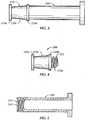
Figs. 1 ,6 and12-15 a first embodiment of a plunger tip, indicated generally at 10.
Theplunger tip 10 has acore 20 engaged with anelastomeric sleeve 30. Thecore 20 is preferably made of a generally rigid material, such as a polymer and, more particularly, a medical grade polypropylene, for instance. Theelastomeric sleeve 30 is preferably made of an elastomeric material (either a thermoplastic elastomer or a thermoset elastomer) having a Shore A hardness of between 30 and 80, and preferably between 40 and 70. Although these materials are preferred, it is within the scope of the present invention that thecore 20 andelastomeric sleeve 30 be made of different materials, provided they are capable of performing as described herein. Theplunger tip 10 is preferably co-injection molded, such that thecore 20 is injection molded first, and then theelastomeric sleeve 30 is injection molded onto thepremolded core 20. Although this is preferred, it is within the spirit and scope of the present invention that theplunger tip 10 be formed using another process, such molding thecore 20 andelastomeric sleeve 30 separately and then assembling theplunger tip 10 thereafter, for instance. - Referring to
Fig. 6 and13 , theelastomeric sleeve 30 is generally tubular having an open bottom and top. Thesleeve 30 has a series ofcircumferential ridges 30b that extend around and radially outward therefrom. Preferably, theelastomeric sleeve 30 has threecircumferential ridges 30b, although it is within the scope that there be more or less than threeridges 30b. - Referring again to
Figs. 1 ,14, and 15 , thecore 20 is generally cylindrical in shape, having a generally cylindricalendless sidewall 20c with a circular flangedfirst end 20b extending outwardly from a bottom thereof and an opposite circular flangedsecond end 20a extending outwardly from a top thereof. Theendless sidewall 20c extends between the first andsecond ends sidewall 20c may have a slight inward slant from thefirst end 20b to thesecond end 20a, as shown slightly exaggerated inFig. 1 . It is further preferable that thesidewall 20c have axially extendedridges 20d extending slightly radially outwardly from thesidewall 20c. Preferably, there are four evenly-spacedridges 20d extending axially along thesidewall 20c, although it is within the scope that there be more or less than fourridges 20d. Theelastomeric sleeve 30 surrounds theendless sidewall 20c such that thesecond end 20a of thecore 20 is exposed. Disposed within thecore 20 is abore 21 extending at least partially therethrough. Formed in a sidewall of thebore 21 is afemale thread 22. - Referring specifically to
Figs. 12 and 13 , thefirst end 20b of thecore 20 is attached to the distal end of aplunger 40 havingmale threads 42 that threadably engage with thefemale threads 22 of thecore 20. Theelastomeric sleeve 30 is preferably disposed between the first andsecond ends sidewall 20c of thecore 20. In this way, theelastomeric sleeve 30 is retained on the core 20 between the first andsecond ends ridges 20d aid in engagement of theelastomeric sleeve 30 with the core 20 by providing disruptions in the otherwise smooth surface of thesidewall 20c, thereby reducing the likelihood of rotation of theelastomeric sleeve 30 with respect to thecore 20. Also, the slight slant to thesidewall 20c of thecore 20 reduces the likelihood of theelastomeric sleeve 30 moving axially downwardly, towards the plunger, and compressing against thefirst end 20b during use of theplunger tip 10. - In use, the
plunger tip 10 is either co-molded or separately molded and assembled. Theplunger tip 10 is then threadably engaged with the distal end of theplunger 40. The distal end of theplunger 40 including theplunger tip 10 can then be inserted within a conventional syringe barrel 400 (seeFig. 11 ). A user then applies a force to the proximal end of theplunger 40 to urge the contents (not shown) out from within the syringe barrel 400. The external diameter of theridges 30b is larger than the interior diameter of the syringe barrel 400 such that theridges 30b of theelastomeric sleeve 30 are compressed between the core 20 and an interior surface of the syringe barrel 400 to create a sliding sealed engagement, thereby preventing the contents of the syringe barrel 400 from escaping from the syringe barrel between theplunger tip 10 and the interior surface of the syringe barrel 400. - Referring to
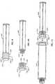
Fig. 2 , there is shown acore 120 in accordance with a second embodiment. - The
core 120 of the second embodiment is similar to thecore 20 of the first embodiment, except that thecore 120 has an extension 120e extending downwardly from abottom flange 120b. The extension 120e allows thecore 120 to accommodatethreads 122 within abore 121 which are wider than a diameter of asidewall 120c of thecore 120. In this way, if it is desired that thesidewall 120c have a diameter that is smaller than a diameter of thethreads 122, thewider threads 122 can be accommodated within the extension 120e of thecore 120. In this way, thewider diameter threads 122 can be contained entirely within thecore 120, and nothreads 122 become exposed through thesidewall 120c. - Referring to
Fig. 3 , there is shown acore 220 in accordance with a third embodiment . Thecore 220 is similar to thecore 20 of the first embodiment, except that thecore 220 is integrally molded with aplunger 240, rather than being threadably engaged therewith. In this way, thecore 220 and theplunger 240 can be molded together and, consequently, do not require additional assembly time to attach thecore 220 to theplunger 240 subsequently, thereby decreasing the time and cost of assembly. - Referring to
Figs. 4 and 5 , there is shown acore 320 in accordance with a fourth embodiment. Thecore 320 is similar to thecore 20 of the first embodiment, except that, instead of female threads disposed within a bore of thecore 320, thecore 320 has male threads 322 extending outwardly from anextension 320e extending downwardly from a bottom of abottom flange 320b. The threads 322 of thecore 320 engage withfemale threads 342 of aplunger 340 disposed within abore 341 that extends at least partially through theplunger 340. - Preferably, each of the above-described
cores elastomeric sleeve 30 of the type shown inFigs. 6 and13 . As stated above, theelastomeric sleeve 30 is preferably co-molded with thecores elastomeric sleeve 30 be molded separately from thecores cores - Referring to
Figs. 7-11 , there is shown aplunger tip 410 in accordance with a fifth embodiment. Theplunger tip 410 has apolymeric core 420 having a generally circular, slightly pointedtip 420a and a generallycylindrical sidewall 420c extending downwardly therefrom. Thecore 420 is preferably constructed of a polymeric material but it may be constructed of any generally rigid materials similar to thecore 20 of the first embodiment. Although shown with apointed tip 420a, it is within the spirit and scope that theplunger tip 420 have a second end similar to 20a of the first embodiment. Disposed around thesidewall 420c are three generally equally, axially spaced, and radially extendingcircumferential ridges 430, rather than thesleeve 30 of the previously-described embodiments. Although shown with threeridges 430, it is within the spirit and scope that theplunger tip 420 have more or less than threeridges 430 disposed along thesidewall 420c of thecore 420. Theplunger tip 410 is secured to the distal end of aplunger 440. Theplunger 440 can be either integrally molded with the core 420 (like thecore 220 andplunger 240 of the third embodiment) or threadably engaged with the core 420 withthreads 442 of theplunger 440 engaging withthreads 422 within abore 421 of the core 420 (like the core 20 andplunger 40 of the first embodiment). The assembledplunger tip 410 andplunger 440 can then be used within a syringe barrel 400 in order to urge the syringe contents (not shown) from within the syringe barrel 400. Theridges 430 providing a sliding seal between the core 420 and an interior surface of the syringe barrel 400 to inhibit the contents from leaking from the syringe barrel 400. - Referring to
Figs. 16-19 , aplunger tip 510 in accordance with a sixth embodiment is shown. Theplunger tip 510 is similar to theplunger tip 10 of the first embodiment, except that acore 520 has no bottom flange, thecore 520 having only atop flange 520a with a generallycylindrical sidewall 520c extending downwardly therefrom. As with the first embodiment, thecore 520 preferably has axially extendingridges 520d extending slightly outwardly from thesidewall 520c. The lack of a bottom flange allows anelastomeric sleeve 530 to be more easily placed on thecore 520, if thecore 520 andelastomeric sleeve 530 are molded separately. Theplunger tip 510 can then be threadably engaged or otherwise attached to aplunger 540, such that atop end 540a of theplunger 540 abuts a bottom of theelastomeric sleeve 530 to act as a bottom flange, thereby preventing theelastomeric sleeve 530 from sliding axially downwardly along thesidewall 520c and retaining theelastomeric sleeve 530 on thecore 520 during use of theplunger tip 510 andplunger 540. - Referring to
Figs. 20-23 , there is shown aplunger tip 610 in accordance with a seventh embodiment. Theplunger tip 610 is similar to theplunger tip 10 of the first embodiment, except that there is no top flange extending from a top of thecore 620, thecore 620 having only a bottom flange at afirst end 620b. Also, asidewall 620c of thecore 620 is essentially smooth and has no ridges. This configuration allows anelastomeric sleeve 630 to be attached to thecore 620 by sliding theelastomeric sleeve 630 over the top of thecore 620 if thecore 620 and thesleeve 630 are molded separately. Theelastomeric sleeve 630 has atop surface 630a that surrounds a second end of thecore 620 when engaged therewith. Although not reducing the amount of elastomeric material in contact with the contents of the syringe barrel, thecore 620 still allows for a relatively rigid connection to be formed between the core 620 and aplunger 640, thereby decreasing the likelihood of misalignment of theplunger tip 610 and theplunger 640 during use. - Referring to
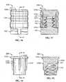
Figs. 24-27 , aplunger tip 710 in accordance with an eighth embodiment is shown. Theplunger tip 710 of the eighth embodiment is similar to theplunger tip 610 of the seventh embodiment, except that asidewall 720c of acore 720 of theplunger tip 710 has a plurality of generally rectangularly-shapeddepressions 720d therein. Although shown as generally rectangularly shaped, it is within the spirit and scope of the present invention that thedepressions 720d have different shapes, such as circular, triangular, or the like. Thedepressions 720d allow for enhanced engagement between the core 720 and anelastomeric sleeve 730 by allowing elastomeric material of theelastomeric sleeve 730 to be disposed within thedepressions 720d during co-molding of theplunger tip 710. Because theelastomeric sleeve 730 is partially disposed within thedepressions 720d, there is less likelihood that theelastomeric sleeve 730 will rotate or move axially with respect to thecore 720 during use. - Referring to
Figs. 28-31 , a plunger tip 710' in accordance with a ninth embodiment of the present invention is shown. The plunger tip 710' of the ninth embodiment is similar to theplunger tip 710 of the eighth embodiment, except a plurality ofcore slots 720e extend axially through the core 720'. Thecore slots 720e are in communication with thedepressions 720d allowing for even further enhanced engagement between the core 720' and anelastomeric sleeve 730 by allowing elastomeric material of theelastomeric sleeve 730 to be disposed within thedepressions 720d and through thecore slots 720e during co-molding of theplunger tip 710. Theelastomeric sleeve 730 is thus partially disposed within thedepressions 720d and locked to the core 720' through thecore slots 720e, preventing theelastomeric sleeve 730 from peeling off or rotating or otherwise moving axially with respect to the core 720' during use. Thecore slots 720e may be part of the molding of the core 720' or subsequently added to thecore 720 by drilling through the top or the bottom of thecore 720. Though thecore slots 720e are shown as extending through the entire core 720', it is within the present invention that the core slots extend only partially through the core 720 from either end of thecore 720. It is also within the invention thatcore slots 720e have different cross sectional shapes, such as circular, triangular, or the like. - Referring to
Figs. 32-34 , aplunger tip 810 in accordance with a tenth embodiment is shown. Theplunger tip 810 of the tenth embodiment is similar to theplunger tip 610 of the seventh embodiment, except that a top of acore 820 of theplunger tip 810 has a generallyannular protrusion 820a extending outwardly from a second end of thecore 820. Although it is preferred that theannular protrusion 820a form a continuous ring, it is within the spirit and scope that theannular protrusion 820a be segmented. Anannular channel 820d is preferably disposed in the second end of the core 820 inwardly of theannular protrusion 820a. Although it is preferred that theannular channel 820d is continuous, it is within the spirit and scope that theannular channel 820d be segmented. Also, although portrayed proximate theannular protrusion 820a, it is within the spirit and scope that theannular channel 820d be located anywhere along the top or second end of thecore 820. The annular protrusion andchannel sleeve 830 by allowing elastomeric material of theelastomeric sleeve 830 to be disposed within theannular channel 820d and around theannular protrusion 820a during co-molding of theplunger tip 810. Because theelastomeric sleeve 830 is partially disposed within theannular channel 820d, there is less likelihood that theelastomeric sleeve 830 will move with respect to thecore 820 during use. - Referring to
Figs. 35 and 36 , aplunger tip 910 in accordance with an eleventh embodiment is shown. In certain applications, such as automatic dosing systems (not shown), for instance, it is desirable to have no plunger attached to theplunger tip 910, thereby allowing acore 920 of theplunger tip 910 to have generally solid top and bottom flanged ends 920a, 920b. That is, neither the top nor the bottom flanged ends 920a, 920b have a hole therein to allow a plunger to be threadably attached or otherwise fixedly engaged with theplunger tip 910. Instead, theplunger tip 910 is preferably intended to be used with an actuator rod (not shown), an end of which abuts and pushes against one of the top and bottom flanged ends 920a, 920b in order to move theplunger tip 910 within the syringe barrel. Anelastomeric sleeve 930 is disposed on the generallyrigid core 920, preferably between the top and bottom flanged ends 920a, 920b. Although thecore 920 is portrayed as being smooth, it is within the spirit and scope that thecore 920 have ridges, depressions, or other similar structures, similar to those described above, to aid in retaining theelastomeric sleeve 930 on thecore 920 and inhibiting rotation and/or axial movement of theelastomeric sleeve 930 with respect to thecore 920. Furthermore, although it is preferred that thecore 920 have top and bottom flanged ends 920a, 920b, it is within the spirit and scope that either or both of theends elastomeric sleeve 730 of the eighth embodiment. - It will be appreciated by those skilled in the art that changes could be made to the embodiments described above without departing from the broad inventive concept thereof. It is understood, therefore, that this invention is not limited to the particular embodiments disclosed, but it is intended to cover modifications within the spirit and scope of the present invention.
Claims (7)
- A plunger tip (710) for being located on a distal end of a syringe plunger and for sliding sealed engagement with an interior surface of a syringe barrel, the interior surface of the syringe barrel having an interior diameter, said plunger tip (710) comprising:a core (720) having an endless sidewall (720c) with a plurality of depressions (720d) therein for being secured to the distal end of the plunger, the core (720) having a first end (720b) for being secured to the plunger, a second end (720a) opposite from said first end (720b), the endless sidewall (720c) extending between the first and second ends (720a, 720b), the core (720) being constructed of a generally rigid material; andan elastomeric sleeve (730) having a series of circumferential ridges extending around and radially outwardly from said elastomeric sleeve (730), wherein an external diameter of the series of circumferential ridges is larger than the interior diameter of the syringe barrel such that only the ridges of the plunger tip (710) are in contact with the interior surface when the plunger tip (710) is slidably engaged with the interior surface, the elastomeric sleeve (730) surrounding the endless sidewall (720c) including having a top surface (730a) surrounding the second end (720a) of the core (720),characterised in that:
the core (720) further comprises core slots (720e) that extend axially through the core (720), wherein the core slots (720e) are in communication with the plurality of depressions (720d); and the elastomeric sleeve (730) is partially disposed within the plurality of depressions (720d) and locked to the core (720) through the core slots (720c) to lessen rotation and axial movement of the elastomeric sleeve (730) with respect to the core (720) during use of the plunger tip (710). - The plunger tip (710) as claimed in claim 1, wherein the core slots (720e) are formed during the molding of the core (720).
- The plunger tip (710) as claimed in claim 1, wherein the core slots (720e) are added to the core (720) by drilling through the top or the bottom of the core (720).
- The plunger tip (710) as claimed in claim 1, wherein the core (720) includes a bore (721) having female threads (722).
- The plunger tip (710) as claimed in claim 1, wherein the core (720) comprises a flanged end (720b) positioned below the elastomeric sleeve (730).
- The plunger tip (710) as claimed in claim 5, wherein the core (720) and the flanged end (720b) have female threads (722) disposed therein.
- A combination syringe plunger and plunger tip, comprising:the plunger tip (710) as claimed in claim 1; anda syringe plunger (740) having a proximal end for the application of a force, a distal end for being positioned within the syringe barrel, and male threads (740) that mate with the female threads (722) disposed in the core (720) and the flanged end (720b).
Applications Claiming Priority (2)
| Application Number | Priority Date | Filing Date | Title |
|---|---|---|---|
| US71232405P | 2005-08-29 | 2005-08-29 | |
| PCT/US2006/033493WO2007027585A2 (en) | 2005-08-29 | 2006-08-29 | Dual material plunger tip for use with a syringe |
Publications (3)
| Publication Number | Publication Date |
|---|---|
| EP1922098A2 EP1922098A2 (en) | 2008-05-21 |
| EP1922098B1 EP1922098B1 (en) | 2017-01-25 |
| EP1922098B2true EP1922098B2 (en) | 2019-10-02 |
Family
ID=37461516
Family Applications (1)
| Application Number | Title | Priority Date | Filing Date |
|---|---|---|---|
| EP06813848.6AActiveEP1922098B2 (en) | 2005-08-29 | 2006-08-29 | Dual material plunger tip for use with a syringe |
Country Status (5)
| Country | Link |
|---|---|
| US (1) | US7749202B2 (en) |
| EP (1) | EP1922098B2 (en) |
| JP (1) | JP4663791B2 (en) |
| CN (1) | CN101252961B (en) |
| WO (1) | WO2007027585A2 (en) |
Families Citing this family (51)
| Publication number | Priority date | Publication date | Assignee | Title |
|---|---|---|---|---|
| WO2008078467A1 (en)* | 2006-12-27 | 2008-07-03 | Daikyo Seiko, Ltd. | Piston for syringe |
| US9295776B2 (en)* | 2008-04-11 | 2016-03-29 | Medtronic Minimed, Inc. | Reservoir plunger head systems and methods |
| EP2251454B1 (en) | 2009-05-13 | 2014-07-23 | SiO2 Medical Products, Inc. | Vessel coating and inspection |
| CN105536110B (en)* | 2009-05-20 | 2020-01-17 | 赛诺菲-安万特德国有限公司 | Stoppers for drug-containing cartridges in drug delivery devices |
| US9458536B2 (en) | 2009-07-02 | 2016-10-04 | Sio2 Medical Products, Inc. | PECVD coating methods for capped syringes, cartridges and other articles |
| JP5431051B2 (en)* | 2009-07-17 | 2014-03-05 | 株式会社大協精工 | A small-capacity piston for a syringe and a plunger to which the piston is attached |
| US8574201B2 (en) | 2009-12-22 | 2013-11-05 | Medtronic Minimed, Inc. | Syringe piston with check valve seal |
| US9265890B2 (en)* | 2009-12-22 | 2016-02-23 | Medtronic Minimed, Inc. | Syringe piston with finned sealing cover |
| US20120165754A1 (en)* | 2009-12-22 | 2012-06-28 | Medtronic Minimed, Inc. | Syringe piston with fin-shaped circumferential sealing element |
| WO2011125133A1 (en)* | 2010-04-09 | 2011-10-13 | 有限会社コーキ・エンジニアリング | Cylinder gasket and pre-filled syringe using same |
| USD665904S1 (en)* | 2010-05-14 | 2012-08-21 | Taisei Kako Co., Ltd. | Plunger rod for a medical syringe |
| US9878101B2 (en) | 2010-11-12 | 2018-01-30 | Sio2 Medical Products, Inc. | Cyclic olefin polymer vessels and vessel coating methods |
| USD663415S1 (en)* | 2011-01-11 | 2012-07-10 | Fuso Pharmaceutical Industries, Ltd. | Syringe plunger rod |
| WO2012101669A1 (en)* | 2011-01-25 | 2012-08-02 | 有限会社コーキ・エンジニアリング | Gasket for syringe and pre-filled syringe using same |
| US9272095B2 (en) | 2011-04-01 | 2016-03-01 | Sio2 Medical Products, Inc. | Vessels, contact surfaces, and coating and inspection apparatus and methods |
| CN102949765A (en)* | 2011-08-22 | 2013-03-06 | 吴振文 | anti-reflux syringe |
| JP2013116289A (en)* | 2011-12-05 | 2013-06-13 | Daikyo Seiko Ltd | Medicine syringe |
| US20130310760A1 (en)* | 2012-05-21 | 2013-11-21 | Becton, Dickinson And Company | Stopper Having a Scale Line Formed Thereon |
| US9901725B2 (en) | 2012-10-01 | 2018-02-27 | Bayer Healthcare Llc | Overmolded medical connector tubing and method |
| US9664626B2 (en) | 2012-11-01 | 2017-05-30 | Sio2 Medical Products, Inc. | Coating inspection method |
| US9903782B2 (en) | 2012-11-16 | 2018-02-27 | Sio2 Medical Products, Inc. | Method and apparatus for detecting rapid barrier coating integrity characteristics |
| US9764093B2 (en) | 2012-11-30 | 2017-09-19 | Sio2 Medical Products, Inc. | Controlling the uniformity of PECVD deposition |
| AU2013352436B2 (en) | 2012-11-30 | 2018-10-25 | Sio2 Medical Products, Inc. | Controlling the uniformity of PECVD deposition on medical syringes, cartridges, and the like |
| US20160015898A1 (en) | 2013-03-01 | 2016-01-21 | Sio2 Medical Products, Inc. | Plasma or cvd pre-treatment for lubricated pharmaceutical package, coating process and apparatus |
| EP2965773A4 (en)* | 2013-03-08 | 2016-10-26 | Nipro Corp | Syringe and syringe gasket |
| JP6453841B2 (en) | 2013-03-11 | 2019-01-16 | エスアイオーツー・メディカル・プロダクツ・インコーポレイテッド | Coated packaging |
| US9937099B2 (en) | 2013-03-11 | 2018-04-10 | Sio2 Medical Products, Inc. | Trilayer coated pharmaceutical packaging with low oxygen transmission rate |
| US20160017490A1 (en) | 2013-03-15 | 2016-01-21 | Sio2 Medical Products, Inc. | Coating method |
| JP6199604B2 (en)* | 2013-05-15 | 2017-09-20 | 住友ゴム工業株式会社 | Medical gasket |
| WO2014194918A1 (en)* | 2013-06-05 | 2014-12-11 | Mediject Aps | Piston for use a syringe with specific dimensional ratio of a sealing structure |
| FR3011472B1 (en)* | 2013-10-09 | 2017-09-01 | Aptar Stelmi Sas | CAP-PISTON AND SYRINGE DEVICE COMPRISING SUCH A PLUG-PISTON |
| GB2529621B (en)* | 2014-08-21 | 2016-12-07 | Owen Mumford Ltd | Safety syringe |
| MY178361A (en)* | 2014-09-10 | 2020-10-09 | Sio2 Medical Products Inc | Three-position plungers, film coated plungers and related syringe assemblies |
| WO2016056038A1 (en) | 2014-10-07 | 2016-04-14 | 有限会社コーキ・エンジニアリング | Slidable medical silicone rubber, gasket using said rubber, and prefilled syringe using said gasket |
| WO2016113409A1 (en)* | 2015-01-16 | 2016-07-21 | Sanofi-Aventis Deutschland Gmbh | Medicament delivery device |
| IL295010B1 (en) | 2015-03-10 | 2025-06-01 | Regeneron Pharma | Pollution-free piercing system and method |
| WO2016153912A1 (en) | 2015-03-24 | 2016-09-29 | Bd Technologies | Time-of-use activated syringe stopper |
| FR3043561B1 (en)* | 2015-11-12 | 2021-11-26 | Guerbet Sa | SYRINGE |
| US10449306B2 (en)* | 2015-11-25 | 2019-10-22 | Medtronics Minimed, Inc. | Systems for fluid delivery with wicking membrane |
| JP1557903S (en)* | 2016-02-12 | 2016-09-05 | ||
| KR102124759B1 (en) | 2016-03-29 | 2020-06-19 | 고키 엔지니어링 유겐가이샤 | High sliding syringe |
| DE102016109505A1 (en)* | 2016-05-24 | 2017-11-30 | Gerresheimer Regensburg Gmbh | Component for a syringe and syringe |
| US20180043102A1 (en)* | 2016-08-09 | 2018-02-15 | Becton, Dickinson And Company | O-Ring Plunger for a Prefilled Syringe and Method |
| CN119950880A (en) | 2017-05-05 | 2025-05-09 | 里珍纳龙药品有限公司 | Auto-injectors and related methods of use |
| JP6300137B1 (en) | 2017-08-29 | 2018-03-28 | 有限会社コーキ・エンジニアリング | Gasket and syringe provided with the same |
| JP6875248B2 (en)* | 2017-10-12 | 2021-05-19 | 株式会社日立ハイテク | Piston and syringe |
| US12076536B2 (en)* | 2018-05-15 | 2024-09-03 | Becton, Dickinson And Company | Syringe plunger stopper for high dose accuracy drug delivery |
| US12162649B2 (en)* | 2020-02-13 | 2024-12-10 | West Pharmaceutical Services, Inc. | Containment and delivery systems for cryogenic storage |
| EP3881877B1 (en)* | 2020-03-17 | 2024-06-12 | Becton Dickinson France | Stopper for a medical injection device |
| USD1007676S1 (en) | 2021-11-16 | 2023-12-12 | Regeneron Pharmaceuticals, Inc. | Wearable autoinjector |
| KR102698010B1 (en)* | 2024-01-19 | 2024-08-23 | (주)디엑스엠 | Syringe capable of removing residual pressure |
Citations (8)
| Publication number | Priority date | Publication date | Assignee | Title |
|---|---|---|---|---|
| US2895773A (en)† | 1956-10-22 | 1959-07-21 | Robert K Mcconnaughey | Variable diameter tensed ring piston |
| US2907330A (en)† | 1958-06-10 | 1959-10-06 | Ernest S V Laub | Compressible plunger for hypodermic syringes |
| WO1995030444A1 (en)† | 1994-05-06 | 1995-11-16 | Nycomed Imaging A/S | Low drag syringe and cartridge |
| EP0925798A2 (en)† | 1997-12-24 | 1999-06-30 | Bracco International B.V. | Easy-slip plunger/plunger rod assembly for a syringe or a cartridge |
| EP1002551A2 (en)† | 1998-11-19 | 2000-05-24 | Bracco International B.V. | Easy-slip plunger/plunger rod assembly for a syringe or a cartridge |
| US20020010431A1 (en)† | 2000-06-08 | 2002-01-24 | Cook Incorporated | High pressure injection syringe |
| US20030097096A1 (en)† | 2000-12-04 | 2003-05-22 | Niedospial John J. | Syringe barrel and plunger assembly having ellipsoidal configurations |
| US20030233075A1 (en)† | 2002-06-14 | 2003-12-18 | Serge Huegli | Piston stopper for injection device, product container and injection device |
Family Cites Families (19)
| Publication number | Priority date | Publication date | Assignee | Title |
|---|---|---|---|---|
| US3577980A (en)* | 1968-05-28 | 1971-05-11 | Milton J Cohen | Fluid extraction device |
| HU189198B (en)* | 1982-12-10 | 1986-06-30 | Adorjan,Andras,Hu | Plastic syringe for single use as well as plastic piston particularly for plastic syringes |
| FR2547201A1 (en) | 1983-06-08 | 1984-12-14 | Villette Alain | Piston for anaesthetic cartridge |
| US4710170A (en) | 1987-02-12 | 1987-12-01 | Habley Medical Technology Corporation | Anti-needle strike and anti-drug abuse syringe |
| JPH0534669Y2 (en)* | 1988-03-16 | 1993-09-02 | ||
| US5314416A (en)* | 1992-06-22 | 1994-05-24 | Sherwood Medical Company | Low friction syring assembly |
| US5314415A (en)* | 1993-07-21 | 1994-05-24 | Sterling Winthrop Inc. | Aspirating plunger for power injector cartridges |
| US5395326A (en) | 1993-10-20 | 1995-03-07 | Habley Medical Technology Corporation | Pharmaceutical storage and mixing syringe having high pressure assisted discharge |
| US5409465A (en)* | 1994-02-07 | 1995-04-25 | Boggs; Michael S. | Impression syringe |
| GB9408773D0 (en)* | 1994-05-04 | 1994-06-22 | Product Research Ltd | Retractable hypodermic syringe |
| US5411488A (en) | 1994-05-06 | 1995-05-02 | Sterling Winthrop Inc. | Pre-filled syringe and pre-filled cartridge having an improved plunger and plunger rod for reducing syringing force |
| US5735825A (en)* | 1996-03-22 | 1998-04-07 | Merit Medical Systems, Inc. | Syringe plunger tip |
| US5873861A (en)* | 1996-11-12 | 1999-02-23 | Medrad, Inc. | Plunger systems |
| US5865803A (en)* | 1997-05-19 | 1999-02-02 | Major; Miklos | Syringe device having a vented piston |
| US6004300A (en)* | 1997-08-28 | 1999-12-21 | Butcher; Robert M | Composite hypodermic syringe piston |
| US6224577B1 (en)* | 1998-03-02 | 2001-05-01 | Medrad, Inc. | Syringes and plungers for use therein |
| JP4132208B2 (en)* | 1998-04-28 | 2008-08-13 | 大成化工株式会社 | Syringe container manufacturing apparatus and syringe container manufacturing method |
| US6334553B1 (en)* | 2000-03-06 | 2002-01-01 | Nordson Corporation | Anti-float plunger for pneumatically actuated syringe |
| US6511459B1 (en)* | 2000-09-29 | 2003-01-28 | Mallinckrodt Inc. | Syringe plunger having an improved sealing ability |
- 2006
- 2006-08-29CNCN2006800319932Apatent/CN101252961B/enactiveActive
- 2006-08-29WOPCT/US2006/033493patent/WO2007027585A2/enactiveApplication Filing
- 2006-08-29JPJP2008529157Apatent/JP4663791B2/enactiveActive
- 2006-08-29EPEP06813848.6Apatent/EP1922098B2/enactiveActive
- 2006-08-29USUS11/468,199patent/US7749202B2/enactiveActive
Patent Citations (9)
| Publication number | Priority date | Publication date | Assignee | Title |
|---|---|---|---|---|
| US2895773A (en)† | 1956-10-22 | 1959-07-21 | Robert K Mcconnaughey | Variable diameter tensed ring piston |
| US2907330A (en)† | 1958-06-10 | 1959-10-06 | Ernest S V Laub | Compressible plunger for hypodermic syringes |
| WO1995030444A1 (en)† | 1994-05-06 | 1995-11-16 | Nycomed Imaging A/S | Low drag syringe and cartridge |
| EP0758255A1 (en)† | 1994-05-06 | 1997-02-19 | Nycomed Imaging A/S | Low drag syringe and cartridge |
| EP0925798A2 (en)† | 1997-12-24 | 1999-06-30 | Bracco International B.V. | Easy-slip plunger/plunger rod assembly for a syringe or a cartridge |
| EP1002551A2 (en)† | 1998-11-19 | 2000-05-24 | Bracco International B.V. | Easy-slip plunger/plunger rod assembly for a syringe or a cartridge |
| US20020010431A1 (en)† | 2000-06-08 | 2002-01-24 | Cook Incorporated | High pressure injection syringe |
| US20030097096A1 (en)† | 2000-12-04 | 2003-05-22 | Niedospial John J. | Syringe barrel and plunger assembly having ellipsoidal configurations |
| US20030233075A1 (en)† | 2002-06-14 | 2003-12-18 | Serge Huegli | Piston stopper for injection device, product container and injection device |
Also Published As
| Publication number | Publication date |
|---|---|
| WO2007027585A2 (en) | 2007-03-08 |
| EP1922098A2 (en) | 2008-05-21 |
| CN101252961B (en) | 2011-07-20 |
| JP2009505794A (en) | 2009-02-12 |
| CN101252961A (en) | 2008-08-27 |
| JP4663791B2 (en) | 2011-04-06 |
| WO2007027585A3 (en) | 2007-05-10 |
| EP1922098B1 (en) | 2017-01-25 |
| US20070060896A1 (en) | 2007-03-15 |
| US7749202B2 (en) | 2010-07-06 |
Similar Documents
| Publication | Publication Date | Title |
|---|---|---|
| EP1922098B2 (en) | Dual material plunger tip for use with a syringe | |
| US11478589B2 (en) | Medical device assembly | |
| US7922958B2 (en) | Method of making an elongate syringe barrel | |
| US7901384B2 (en) | Dosage device | |
| JP6693871B2 (en) | Adapters for drug delivery devices and methods for mounting said adapters therein | |
| EP3104912B1 (en) | Injection needle covering system | |
| EP3334483B1 (en) | A stopper for a medicament container | |
| JP2008264256A (en) | Prefilled syringe and manufacturing method of prefilled syringe | |
| EP4049708A1 (en) | Connector assembly and manufacturing process of the same | |
| WO2024072547A1 (en) | Sealing cap for a syringe tip | |
| AU2017265125A1 (en) | Medical device assembly |
Legal Events
| Date | Code | Title | Description |
|---|---|---|---|
| PUAI | Public reference made under article 153(3) epc to a published international application that has entered the european phase | Free format text:ORIGINAL CODE: 0009012 | |
| 17P | Request for examination filed | Effective date:20080312 | |
| AK | Designated contracting states | Kind code of ref document:A2 Designated state(s):AT BE BG CH CY CZ DE DK EE ES FI FR GB GR HU IE IS IT LI LT LU LV MC NL PL PT RO SE SI SK TR | |
| RIN1 | Information on inventor provided before grant (corrected) | Inventor name:STARUSBAUGH, NEIL Inventor name:WOLFE, JOHN, R. Inventor name:EATON, ANTHONY, L. Inventor name:MILLER, TIMOTHY, M. | |
| DAX | Request for extension of the european patent (deleted) | ||
| 17Q | First examination report despatched | Effective date:20150224 | |
| GRAP | Despatch of communication of intention to grant a patent | Free format text:ORIGINAL CODE: EPIDOSNIGR1 | |
| INTG | Intention to grant announced | Effective date:20151111 | |
| INTC | Intention to grant announced (deleted) | ||
| GRAJ | Information related to disapproval of communication of intention to grant by the applicant or resumption of examination proceedings by the epo deleted | Free format text:ORIGINAL CODE: EPIDOSDIGR1 | |
| GRAP | Despatch of communication of intention to grant a patent | Free format text:ORIGINAL CODE: EPIDOSNIGR1 | |
| GRAR | Information related to intention to grant a patent recorded | Free format text:ORIGINAL CODE: EPIDOSNIGR71 | |
| GRAS | Grant fee paid | Free format text:ORIGINAL CODE: EPIDOSNIGR3 | |
| GRAA | (expected) grant | Free format text:ORIGINAL CODE: 0009210 | |
| AK | Designated contracting states | Kind code of ref document:B1 Designated state(s):AT BE BG CH CY CZ DE DK EE ES FI FR GB GR HU IE IS IT LI LT LU LV MC NL PL PT RO SE SI SK TR | |
| INTG | Intention to grant announced | Effective date:20161220 | |
| REG | Reference to a national code | Ref country code:GB Ref legal event code:FG4D | |
| REG | Reference to a national code | Ref country code:CH Ref legal event code:EP | |
| REG | Reference to a national code | Ref country code:AT Ref legal event code:REF Ref document number:863760 Country of ref document:AT Kind code of ref document:T Effective date:20170215 | |
| REG | Reference to a national code | Ref country code:IE Ref legal event code:FG4D | |
| REG | Reference to a national code | Ref country code:DE Ref legal event code:R096 Ref document number:602006051649 Country of ref document:DE | |
| REG | Reference to a national code | Ref country code:LT Ref legal event code:MG4D | |
| REG | Reference to a national code | Ref country code:NL Ref legal event code:MP Effective date:20170125 | |
| REG | Reference to a national code | Ref country code:AT Ref legal event code:MK05 Ref document number:863760 Country of ref document:AT Kind code of ref document:T Effective date:20170125 | |
| PG25 | Lapsed in a contracting state [announced via postgrant information from national office to epo] | Ref country code:NL Free format text:LAPSE BECAUSE OF FAILURE TO SUBMIT A TRANSLATION OF THE DESCRIPTION OR TO PAY THE FEE WITHIN THE PRESCRIBED TIME-LIMIT Effective date:20170125 | |
| PG25 | Lapsed in a contracting state [announced via postgrant information from national office to epo] | Ref country code:LT Free format text:LAPSE BECAUSE OF FAILURE TO SUBMIT A TRANSLATION OF THE DESCRIPTION OR TO PAY THE FEE WITHIN THE PRESCRIBED TIME-LIMIT Effective date:20170125 Ref country code:IS Free format text:LAPSE BECAUSE OF FAILURE TO SUBMIT A TRANSLATION OF THE DESCRIPTION OR TO PAY THE FEE WITHIN THE PRESCRIBED TIME-LIMIT Effective date:20170525 Ref country code:FI Free format text:LAPSE BECAUSE OF FAILURE TO SUBMIT A TRANSLATION OF THE DESCRIPTION OR TO PAY THE FEE WITHIN THE PRESCRIBED TIME-LIMIT Effective date:20170125 Ref country code:GR Free format text:LAPSE BECAUSE OF FAILURE TO SUBMIT A TRANSLATION OF THE DESCRIPTION OR TO PAY THE FEE WITHIN THE PRESCRIBED TIME-LIMIT Effective date:20170426 | |
| REG | Reference to a national code | Ref country code:FR Ref legal event code:PLFP Year of fee payment:12 | |
| PG25 | Lapsed in a contracting state [announced via postgrant information from national office to epo] | Ref country code:PL Free format text:LAPSE BECAUSE OF FAILURE TO SUBMIT A TRANSLATION OF THE DESCRIPTION OR TO PAY THE FEE WITHIN THE PRESCRIBED TIME-LIMIT Effective date:20170125 Ref country code:PT Free format text:LAPSE BECAUSE OF FAILURE TO SUBMIT A TRANSLATION OF THE DESCRIPTION OR TO PAY THE FEE WITHIN THE PRESCRIBED TIME-LIMIT Effective date:20170525 Ref country code:LV Free format text:LAPSE BECAUSE OF FAILURE TO SUBMIT A TRANSLATION OF THE DESCRIPTION OR TO PAY THE FEE WITHIN THE PRESCRIBED TIME-LIMIT Effective date:20170125 Ref country code:ES Free format text:LAPSE BECAUSE OF FAILURE TO SUBMIT A TRANSLATION OF THE DESCRIPTION OR TO PAY THE FEE WITHIN THE PRESCRIBED TIME-LIMIT Effective date:20170125 Ref country code:AT Free format text:LAPSE BECAUSE OF FAILURE TO SUBMIT A TRANSLATION OF THE DESCRIPTION OR TO PAY THE FEE WITHIN THE PRESCRIBED TIME-LIMIT Effective date:20170125 Ref country code:BG Free format text:LAPSE BECAUSE OF FAILURE TO SUBMIT A TRANSLATION OF THE DESCRIPTION OR TO PAY THE FEE WITHIN THE PRESCRIBED TIME-LIMIT Effective date:20170425 Ref country code:SE Free format text:LAPSE BECAUSE OF FAILURE TO SUBMIT A TRANSLATION OF THE DESCRIPTION OR TO PAY THE FEE WITHIN THE PRESCRIBED TIME-LIMIT Effective date:20170125 | |
| REG | Reference to a national code | Ref country code:DE Ref legal event code:R026 Ref document number:602006051649 Country of ref document:DE | |
| PLBI | Opposition filed | Free format text:ORIGINAL CODE: 0009260 | |
| PG25 | Lapsed in a contracting state [announced via postgrant information from national office to epo] | Ref country code:CZ Free format text:LAPSE BECAUSE OF FAILURE TO SUBMIT A TRANSLATION OF THE DESCRIPTION OR TO PAY THE FEE WITHIN THE PRESCRIBED TIME-LIMIT Effective date:20170125 Ref country code:EE Free format text:LAPSE BECAUSE OF FAILURE TO SUBMIT A TRANSLATION OF THE DESCRIPTION OR TO PAY THE FEE WITHIN THE PRESCRIBED TIME-LIMIT Effective date:20170125 Ref country code:RO Free format text:LAPSE BECAUSE OF FAILURE TO SUBMIT A TRANSLATION OF THE DESCRIPTION OR TO PAY THE FEE WITHIN THE PRESCRIBED TIME-LIMIT Effective date:20170125 Ref country code:SK Free format text:LAPSE BECAUSE OF FAILURE TO SUBMIT A TRANSLATION OF THE DESCRIPTION OR TO PAY THE FEE WITHIN THE PRESCRIBED TIME-LIMIT Effective date:20170125 Ref country code:IT Free format text:LAPSE BECAUSE OF FAILURE TO SUBMIT A TRANSLATION OF THE DESCRIPTION OR TO PAY THE FEE WITHIN THE PRESCRIBED TIME-LIMIT Effective date:20170125 | |
| 26 | Opposition filed | Opponent name:THOMSON, NEIL DAVID Effective date:20171025 | |
| PG25 | Lapsed in a contracting state [announced via postgrant information from national office to epo] | Ref country code:DK Free format text:LAPSE BECAUSE OF FAILURE TO SUBMIT A TRANSLATION OF THE DESCRIPTION OR TO PAY THE FEE WITHIN THE PRESCRIBED TIME-LIMIT Effective date:20170125 | |
| PLAX | Notice of opposition and request to file observation + time limit sent | Free format text:ORIGINAL CODE: EPIDOSNOBS2 | |
| PG25 | Lapsed in a contracting state [announced via postgrant information from national office to epo] | Ref country code:SI Free format text:LAPSE BECAUSE OF FAILURE TO SUBMIT A TRANSLATION OF THE DESCRIPTION OR TO PAY THE FEE WITHIN THE PRESCRIBED TIME-LIMIT Effective date:20170125 | |
| REG | Reference to a national code | Ref country code:CH Ref legal event code:PL | |
| PG25 | Lapsed in a contracting state [announced via postgrant information from national office to epo] | Ref country code:MC Free format text:LAPSE BECAUSE OF FAILURE TO SUBMIT A TRANSLATION OF THE DESCRIPTION OR TO PAY THE FEE WITHIN THE PRESCRIBED TIME-LIMIT Effective date:20170125 | |
| PLBB | Reply of patent proprietor to notice(s) of opposition received | Free format text:ORIGINAL CODE: EPIDOSNOBS3 | |
| PG25 | Lapsed in a contracting state [announced via postgrant information from national office to epo] | Ref country code:CH Free format text:LAPSE BECAUSE OF NON-PAYMENT OF DUE FEES Effective date:20170831 Ref country code:LI Free format text:LAPSE BECAUSE OF NON-PAYMENT OF DUE FEES Effective date:20170831 | |
| REG | Reference to a national code | Ref country code:BE Ref legal event code:MM Effective date:20170831 | |
| PG25 | Lapsed in a contracting state [announced via postgrant information from national office to epo] | Ref country code:LU Free format text:LAPSE BECAUSE OF NON-PAYMENT OF DUE FEES Effective date:20170829 | |
| REG | Reference to a national code | Ref country code:FR Ref legal event code:PLFP Year of fee payment:13 | |
| PG25 | Lapsed in a contracting state [announced via postgrant information from national office to epo] | Ref country code:BE Free format text:LAPSE BECAUSE OF NON-PAYMENT OF DUE FEES Effective date:20170831 | |
| PG25 | Lapsed in a contracting state [announced via postgrant information from national office to epo] | Ref country code:HU Free format text:LAPSE BECAUSE OF FAILURE TO SUBMIT A TRANSLATION OF THE DESCRIPTION OR TO PAY THE FEE WITHIN THE PRESCRIBED TIME-LIMIT; INVALID AB INITIO Effective date:20060829 | |
| PUAH | Patent maintained in amended form | Free format text:ORIGINAL CODE: 0009272 | |
| STAA | Information on the status of an ep patent application or granted ep patent | Free format text:STATUS: PATENT MAINTAINED AS AMENDED | |
| 27A | Patent maintained in amended form | Effective date:20191002 | |
| AK | Designated contracting states | Kind code of ref document:B2 Designated state(s):AT BE BG CH CY CZ DE DK EE ES FI FR GB GR HU IE IS IT LI LT LU LV MC NL PL PT RO SE SI SK TR | |
| REG | Reference to a national code | Ref country code:DE Ref legal event code:R102 Ref document number:602006051649 Country of ref document:DE | |
| PG25 | Lapsed in a contracting state [announced via postgrant information from national office to epo] | Ref country code:CY Free format text:LAPSE BECAUSE OF NON-PAYMENT OF DUE FEES Effective date:20170125 | |
| PG25 | Lapsed in a contracting state [announced via postgrant information from national office to epo] | Ref country code:TR Free format text:LAPSE BECAUSE OF FAILURE TO SUBMIT A TRANSLATION OF THE DESCRIPTION OR TO PAY THE FEE WITHIN THE PRESCRIBED TIME-LIMIT Effective date:20170125 | |
| P01 | Opt-out of the competence of the unified patent court (upc) registered | Effective date:20230529 | |
| PGFP | Annual fee paid to national office [announced via postgrant information from national office to epo] | Ref country code:DE Payment date:20240828 Year of fee payment:19 Ref country code:IE Payment date:20240827 Year of fee payment:19 | |
| PGFP | Annual fee paid to national office [announced via postgrant information from national office to epo] | Ref country code:GB Payment date:20240827 Year of fee payment:19 | |
| PGFP | Annual fee paid to national office [announced via postgrant information from national office to epo] | Ref country code:FR Payment date:20240826 Year of fee payment:19 |