EP1921565A1 - Bar code reader - Google Patents
Bar code readerDownload PDFInfo
- Publication number
- EP1921565A1 EP1921565A1EP07019992AEP07019992AEP1921565A1EP 1921565 A1EP1921565 A1EP 1921565A1EP 07019992 AEP07019992 AEP 07019992AEP 07019992 AEP07019992 AEP 07019992AEP 1921565 A1EP1921565 A1EP 1921565A1
- Authority
- EP
- European Patent Office
- Prior art keywords
- light beams
- barcode reader
- reader according
- receiver
- transmitter
- Prior art date
- Legal status (The legal status is an assumption and is not a legal conclusion. Google has not performed a legal analysis and makes no representation as to the accuracy of the status listed.)
- Granted
Links
Images

Classifications
- G—PHYSICS
- G06—COMPUTING OR CALCULATING; COUNTING
- G06K—GRAPHICAL DATA READING; PRESENTATION OF DATA; RECORD CARRIERS; HANDLING RECORD CARRIERS
- G06K7/00—Methods or arrangements for sensing record carriers, e.g. for reading patterns
- G06K7/10—Methods or arrangements for sensing record carriers, e.g. for reading patterns by electromagnetic radiation, e.g. optical sensing; by corpuscular radiation
- G06K7/10544—Methods or arrangements for sensing record carriers, e.g. for reading patterns by electromagnetic radiation, e.g. optical sensing; by corpuscular radiation by scanning of the records by radiation in the optical part of the electromagnetic spectrum
- G06K7/10554—Moving beam scanning
- G06K7/10594—Beam path
- G06K7/10683—Arrangement of fixed elements
- G06K7/10702—Particularities of propagating elements, e.g. lenses, mirrors
Definitions
- the inventionrelates to a bar code reader according to the preamble of claim 1.
- Such barcode readersare used to detect barcodes that consist of a sequence of light and dark line elements of predetermined width.
- the bar code readercomprises a transmitter which emits transmitted light beams, preferably laser beams.
- the transmitted light beamshave a mean diameter corresponding to their spatial intensity distribution perpendicular to the propagation direction.
- the spatial intensity distributionideally corresponds to a Gaussian distribution.
- the diameter of the transmitted light beamsvaries with the distance to the bar code reader according to the embodiment of a transmitting optics, which is arranged downstream of the transmitter.
- the transmission opticsconsists of a lens.
- the diameter of the transmitted light beamsis usually considerably smaller than the width of the barcode line elements.
- the amplitude modulation of the received signalsis almost identical to the widths of the bar code line elements, so that they can be reliably detected by the bar code reader.
- the diameter of the transmitted light beamsrapidly becomes larger.
- the modulation of the received signalis influenced by the width of the transmitted light beam in such a way that reliable detection of the barcode is made difficult or no longer possible.
- barcodescan be reliably detected with the transmitted light beams only if they are arranged within a narrow reading range, ie a reading distance around the focal plane.
- a barcode readeris known, in which the extension of the reading range, the analog received signals are fed at the output of the receiver to an n-bit analog-to-digital converter. The resulting digitized received signals are read into a digital filter.
- the transmission characteristic of the digital filteris chosen such that within a predetermined tolerance range it corresponds to the inverse of the frequency spectrum of the spatial intensity distribution of the transmitted light beams at the location of the barcode to be detected.
- the time-dependent coefficients of the digital filterare calculated in a variation method comprising several iteration steps.
- the disadvantage hereis that to increase the reading range, a complex evaluation is necessary. Although the determination of the coefficients of the filter need only be carried out before the bar code reader is put into operation. However, a considerable amount of computing power is necessary to determine the coefficients. In addition, the boundary conditions for the variation method must be chosen very carefully so that meaningful results are obtained for the transfer characteristic. This requires to an increased effort and on the other hand requires an increased expertise in determining the transmission characteristics of the digital filter.
- the inventionhas the object of providing a bar code reader of the type mentioned in such a way that its functionality is extended with the least possible structural complexity.
- the barcode readerserves to detect barcodes within a scanning range and comprises a transmitter emitting light beams, a receiving light beam receiving receiver, an evaluation unit for evaluating the received signals at the output of the receiver and a deflection unit, by means of which the transmitted light beams are periodically guided within the scanning range.
- the transmitteris assigned as a transmission lens, a liquid lens whose focal length is adjustable by applying an electrical voltage.
- a significant advantage of the barcode reader according to the inventionis that the focal position of the transmitted light beams can be changed by the liquid lens in a purely electrical way and thus without mechanical adjusting devices and in particular without moving masses.
- the setting of the focus positioncan therefore be carried out wear-free, fast and with low power consumption.
- the electrical focus adjustment that can be carried out with the liquid lenscan be used to set the reading range of the barcode reader.
- the bar code readercan thus be adapted quickly and easily to different reading distances in which there are barcodes to be detected.
- the adjustment made for this purposecan be carried out as a function of external control signals which are read in by central computers, control stations or control systems.
- a distance sensorcan additionally be integrated in the barcode reader, so that the current distance of a barcode to be detected can be determined therewith and the reading range can be adapted to this distance value by means of a focus adjustment of the liquid lens.
- a periodic, continuous change of the focal position of the transmitted light beamscan be made by a corresponding adjustment of the liquid lens.
- the frequency of the change of the focus positionhere is significantly smaller than the sampling rate with which the transmitted light beams sweep over the scanning region. This ensures that during a scanning period within which the transmitted light beams sweep over the scanning area for detecting a barcode, the focal position of the transmitted light beams is approximately constant.
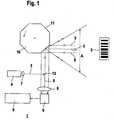
- FIG. 1shows an exemplary embodiment of a barcode reader 1 for detecting barcodes 2 within a scanning range A.
- the barcodes 2consist of a sequence of black and white line elements.
- the bar code reader 1has a transmitting light rays 3 emitting transmitter 4 and a receiving light beams 5 receiving receiver 6.
- the transmitter 4is formed by a laser diode
- the receiver 6consists of a photodiode or the like.
- the transmitter 4is followed by a transmitting optics 7.
- the receiver 6is preceded by a receiving optics 8, by means of which the received light beams 5 are focused on the receiver 6.
- the receiver 6is connected to an evaluation unit 9.
- the evaluation unit 9is formed by a microcontroller or the like.
- the transmitted light beams 3are periodically guided within the scanning range.
- a deflection unitis provided, via which both the transmitted light beams 3 and the received light beams 5 are guided.
- the deflection unitis formed by a motor-driven, rotating polygon mirror wheel 10.
- the polygonal mirror wheel 10has a plurality of identical mirror surfaces 11, wherein eight such mirror surfaces 11 are provided in the present example.
- the transmitting and receiving light beams 5are each guided over the same mirror surface 11 of the polygon mirror wheel 10.
- the beam axes of the incident on the Polygonaptrad 10 transmitted light beams 3 and reflected at the polygon mirror 10 receiving light beams 5are coaxial with each other.
- the coaxial beam guidance of the transmitting and receiving light beams 5 in this areais achieved, for example, by means of a beam splitter 12 which deflects the transmitted light beams 3 as shown in FIG.
- the received light beams 5, which are reflected at the polygon mirror 10,are guided past the beam splitter 12 to the receiver 6.
- the transmitted light beams 3are periodically deflected within an angular range which forms the scanning region A.
- the size of the angle rangeis predetermined by the number of mirror surfaces 11 of the polygon mirror wheel 10.
- a barcode 2 arranged in the scanning area Ais periodically scanned.
- the received light beams 5 reflected on the bar code 2have an amplitude modulation in accordance with the pattern of the line elements of the bar code 2. Accordingly, the received signals at the output of the receiver 6, received signals generated by the received light beams 5, also have a corresponding amplitude modulation. This amplitude modulation of the received signals is evaluated in the evaluation unit 9 for decoding the respective barcode 2.
- the transmission optics 7is designed as a liquid lens whose focal length is electrically adjustable.
- Figures 2a, bshow schematically the structure and operation of the liquid lens.
- the liquid lenshas an insulating liquid 13 and conductive liquid 14, which are mounted in a closed enclosure 15 whose end faces are formed by glass plates 16, 17, through which the transmitted light beams 3 can be guided.
- electrodes 18In the side walls of the enclosure 15 are electrodes 18.
- the change of the reading range of the barcode reader 1can be continuous or discontinuous.
- the focal length of the liquid lenscan be changed by reading a signal from an external unit.
- the change in the focal length of the liquid lenscan be changed as a function of the distances of objects, in particular as a function of the respective distance of the barcode 2 to be detected.
- a separate distance sensorcan be integrated in the barcode reader 1.
- the transmitter 4 and the receiver 6 of the bar code reader 1itself can form a distance sensor.
- the reading rangeis continuously varied by periodically varying the focal length within a predetermined range.
- the frequency of the focal length changeis substantially less than the sampling rate with which the transmitted light beams 3 sweep the scanning range, so that the focal length during a scanning period is substantially unchanged.
Landscapes
- Physics & Mathematics (AREA)
- Engineering & Computer Science (AREA)
- Electromagnetism (AREA)
- Artificial Intelligence (AREA)
- Toxicology (AREA)
- General Health & Medical Sciences (AREA)
- Health & Medical Sciences (AREA)
- Computer Vision & Pattern Recognition (AREA)
- General Physics & Mathematics (AREA)
- Theoretical Computer Science (AREA)
- Optical Communication System (AREA)
- Mechanical Optical Scanning Systems (AREA)
- Investigating Or Analysing Materials By Optical Means (AREA)
- Optical Radar Systems And Details Thereof (AREA)
Abstract
Description
Translated fromGermanDie Erfindung betrifft ein Barcodelesegerät gemäß dem Oberbegriff des Anspruchs 1.The invention relates to a bar code reader according to the preamble of
Derartige Barcodelesegeräte dienen zur Detektion von Barcodes, die aus einer Folge von hellen und dunklen Linienelementen vorgegebener Breite bestehen. Das Barcodelesegerät umfasst einen Sender, welcher Sendelichtstrahlen, vorzugsweise Laserstrahlen, emittiert. Die Sendelichtstrahlen weisen einen mittleren Durchmesser entsprechend ihrer räumlichen Intensitätsverteilung senkrecht zur Ausbreitungsrichtung auf. Bei Laserstrahlen entspricht die räumliche Intensitätsverteilung idealerweise einer Gaußverteilung.Such barcode readers are used to detect barcodes that consist of a sequence of light and dark line elements of predetermined width. The bar code reader comprises a transmitter which emits transmitted light beams, preferably laser beams. The transmitted light beams have a mean diameter corresponding to their spatial intensity distribution perpendicular to the propagation direction. For laser beams, the spatial intensity distribution ideally corresponds to a Gaussian distribution.
Der Durchmesser der Sendelichtstrahlen variiert mit dem Abstand zum Barcodelesegerät entsprechend der Ausgestaltung einer Sendeoptik, die dem Sender nachgeordnet ist. Die Sendeoptik besteht aus einer Linse. In der Brennebene der Sendelichtstrahlen ist der Durchmesser der Sendelichtstrahlen üblicherweise erheblich kleiner als die Breite der Linienelemente des Barcodes. Demzufolge ist die Amplitudenmodulation der Empfangssignale nahezu identisch mit den Breiten der Linienelemente des Barcodes, so dass diese von dem Barcodelesegerät sicher erkannt werden kann.The diameter of the transmitted light beams varies with the distance to the bar code reader according to the embodiment of a transmitting optics, which is arranged downstream of the transmitter. The transmission optics consists of a lens. In the focal plane of the transmitted light beams, the diameter of the transmitted light beams is usually considerably smaller than the width of the barcode line elements. As a result, the amplitude modulation of the received signals is almost identical to the widths of the bar code line elements, so that they can be reliably detected by the bar code reader.
Mit zunehmender Entfernung des Barcodes von der Brennebene der Sendelichtstrahlen wird der Durchmesser der Sendelichtstrahlen rasch größer. Sobald der Durchmesser der Sendelichtstrahlen von gleicher Größenordnung wie die Breiten der Linienelemente der Barcodes ist, wird die Modulation des Empfangssignals durch die Breite des Sendelichtstrahls so beeinflusst, dass eine sichere Detektion des Barcodes erschwert wird oder nicht mehr möglich ist.With increasing distance of the bar code from the focal plane of the transmitted light beams, the diameter of the transmitted light beams rapidly becomes larger. As soon as the diameter of the transmitted light beams is of the same order of magnitude as the widths of the line elements of the barcodes, the modulation of the received signal is influenced by the width of the transmitted light beam in such a way that reliable detection of the barcode is made difficult or no longer possible.
Somit können mit den Sendelichtstrahlen Barcodes nur dann sicher erfasst werden, wenn diese innerhalb eines eng begrenzten Lesebereichs, das heißt eines Leseabstands um die Brennebene angeordnet sind.Thus, barcodes can be reliably detected with the transmitted light beams only if they are arranged within a narrow reading range, ie a reading distance around the focal plane.
Aus der
Mit der auf diese Weise bestimmten Übertragungscharakteristik des digitalen Filters können Signalverzerrungen, welche durch den endlichen Durchmesser der Sendelichtstrahlen bei der Abtastung der Barcodes auftreten, weitgehend eliminiert werden. Dadurch kann der nutzbare Lesebereich des Barcodelesegeräts erheblich erweitert werden.With the transmission characteristic of the digital filter determined in this way, signal distortions which occur due to the finite diameter of the transmitted light beams when scanning the barcodes can be largely eliminated. As a result, the usable reading range of the barcode reader can be considerably expanded.
Nachteilig hierbei ist jedoch, dass zur Vergrößerung des Lesebereichs ein aufwendiges Auswerteverfahren nötig ist. Zwar braucht die Bestimmung der Koeffizienten des Filters lediglich vor Inbetriebnahme des Barcodelesegeräts durchgeführt werden. Jedoch ist zur Bestimmung der Koeffizienten ein erheblicher Aufwand an Rechenleistung notwendig. Zudem müssen die Randbedingungen für das Variationsverfahren sehr sorgfältig gewählt werden, damit für die Übertragungscharakteristik sinnvolle Ergebnisse erhalten werden. Dies bedingt zum einen erhöhten Aufwand und erfordert zum anderen ein erhöhtes Fachwissen bei der Festlegung der Übertragungscharakteristik des digitalen Filters.The disadvantage here, however, is that to increase the reading range, a complex evaluation is necessary. Although the determination of the coefficients of the filter need only be carried out before the bar code reader is put into operation. However, a considerable amount of computing power is necessary to determine the coefficients. In addition, the boundary conditions for the variation method must be chosen very carefully so that meaningful results are obtained for the transfer characteristic. This requires to an increased effort and on the other hand requires an increased expertise in determining the transmission characteristics of the digital filter.
Der Erfindung liegt die Aufgabe zugrunde, ein Barcodelesegerät der eingangs genannten Art so auszubilden, dass dessen Funktionalität mit möglichst geringem baulichen Aufwand erweitert wird.The invention has the object of providing a bar code reader of the type mentioned in such a way that its functionality is extended with the least possible structural complexity.
Zur Lösung dieser Aufgabe sind die Merkmale des Anspruchs 1 vorgesehen. Vorteilhafte Ausführungsformen und zweckmäßige Weiterbildungen der Erfindung sind in den Unteransprüchen beschrieben.To solve this problem, the features of
Das erfindungsgemäße Barcodelesegerät dient zur Detektion von Barcodes innerhalb eines Abtastbereichs und umfasst einen Sendelichtstrahlen emittierenden Sender, einen Empfangslichtstrahlen empfangenden Empfänger, eine Auswerteeinheit zur Auswertung der am Ausgang des Empfängers anstehenden Empfangssignale und eine Ablenkeinheit, mittels derer die Sendelichtstrahlen periodisch innerhalb des Abtastbereichs geführt sind. Dem Sender ist als Sendeoptik eine Flüssigkeitslinse zugeordnet, deren Brennweite durch Anlegen einer elektrischen Spannung einstellbar ist.The barcode reader according to the invention serves to detect barcodes within a scanning range and comprises a transmitter emitting light beams, a receiving light beam receiving receiver, an evaluation unit for evaluating the received signals at the output of the receiver and a deflection unit, by means of which the transmitted light beams are periodically guided within the scanning range. The transmitter is assigned as a transmission lens, a liquid lens whose focal length is adjustable by applying an electrical voltage.
Ein wesentlicher Vorteil des erfindungsgemäßen Barcodelesegeräts besteht darin, dass die Fokuslage der Sendelichtstrahlen durch die Flüssigkeitslinse auf rein elektrischem Weg und damit ohne mechanische Stellvorrichtungen und insbesondere ohne bewegte Massen verändert werden kann. Die Einstellung der Fokuslage kann daher verschleißfrei, schnell und mit geringem Leistungsverbrauch durchgeführt werden.A significant advantage of the barcode reader according to the invention is that the focal position of the transmitted light beams can be changed by the liquid lens in a purely electrical way and thus without mechanical adjusting devices and in particular without moving masses. The setting of the focus position can therefore be carried out wear-free, fast and with low power consumption.
Besonders vorteilhaft kann die mit der Flüssigkeitslinse durchführbare elektrische Fokusverstellung zur Einstellung des Lesebereichs des Barcodelesegeräts eingesetzt werden.Particularly advantageously, the electrical focus adjustment that can be carried out with the liquid lens can be used to set the reading range of the barcode reader.
Das Barcodelesegerät kann somit schnell und einfach an unterschiedliche Leseabstände, in denen sich zu detektierende Barcodes befinden, angepasst werden.The bar code reader can thus be adapted quickly and easily to different reading distances in which there are barcodes to be detected.
Die hierfür vorgenommene Anpassung kann in Abhängigkeit von externen Steuersignalen erfolgen, die von Zentralrechnern, Leitständen oder Steuerungen eingelesen werden.The adjustment made for this purpose can be carried out as a function of external control signals which are read in by central computers, control stations or control systems.
Alternativ oder zusätzlich kann in dem Barcodelesegerät zusätzlich ein Distanzsensor integriert sein, so dass mit diesem die aktuelle Distanz eines zu detektierenden Barcodes bestimmt werden kann und der Lesebereich durch eine Fokusverstellung der Flüssigkeitslinse an diesen Distanzwert angepasst werden kann.Alternatively or additionally, a distance sensor can additionally be integrated in the barcode reader, so that the current distance of a barcode to be detected can be determined therewith and the reading range can be adapted to this distance value by means of a focus adjustment of the liquid lens.
Weiterhin kann zur Erzielung eines großen nutzbaren Lesebereichs auch eine periodische, kontinuierliche Änderung der Fokuslage der Sendelichtstrahlen durch eine entsprechende Einstellung der Flüssigkeitslinse vorgenommen werden. Zweckmäßigerweise ist hier die Frequenz der Änderung der Fokuslage signifikant kleiner als die Abtastrate, mit welcher die Sendelichtstrahlen den Abtastbereich überstreichen. Dadurch ist gewährleistet, dass während einer Abtastperiode, innerhalb derer die Sendelichtstrahlen den Abtastbereich zur Detektion eines Barcodes überstreichen, die Fokuslage der Sendelichtstrahlen näherungsweise konstant ist.Furthermore, to achieve a large usable reading range, a periodic, continuous change of the focal position of the transmitted light beams can be made by a corresponding adjustment of the liquid lens. Expediently, the frequency of the change of the focus position here is significantly smaller than the sampling rate with which the transmitted light beams sweep over the scanning region. This ensures that during a scanning period within which the transmitted light beams sweep over the scanning area for detecting a barcode, the focal position of the transmitted light beams is approximately constant.
Die Erfindung wird im Nachstehenden anhand der Zeichnungen erläutert. Es zeigen:
- Figur 1:
- Schematische Darstellung eines Ausführungsbeispiels eines Barcodelesegeräts.
- Figur 2a, b:
- Schematische Darstellung einer die Sendeoptik des Barcodelesegeräts gemäß
Figur 1 bildenden Flüssigkeitslinse für zwei unterschiedliche Ansteuerungen.
- FIG. 1:
- Schematic representation of an embodiment of a barcode reader.
- FIG. 2a, b:
- Schematic representation of a transmission lens of the bar code reader according to Figure 1 forming liquid lens for two different controls.
Figur 1 zeigt ein Ausführungsbeispiel eines Barcodelesegeräts 1 zum Erfassen von Barcodes 2 innerhalb eines Abtastbereichs A. Die Barcodes 2 bestehen aus einer Folge von schwarzen und weißen Linienelementen.FIG. 1 shows an exemplary embodiment of a
Das Barcodelesegerät 1 weist einen Sendelichtstrahlen 3 emittierenden Sender 4 und einen Empfangslichtstrahlen 5 empfangenden Empfänger 6 auf.The
Der Sender 4 ist von einer Laserdiode gebildet, der Empfänger 6 besteht aus einer Fotodiode oder dergleichen.The
Zur Strahlformung der Sendelichtstrahlen 3 ist dem Sender 4 eine Sendeoptik 7 nachgeordnet. Dem Empfänger 6 ist eine Empfangsoptik 8 vorgeordnet, mittels derer die Empfangslichtstrahlen 5 auf den Empfänger 6 fokussiert werden.For beam shaping of the transmitted
Der Empfänger 6 ist an eine Auswerteeinheit 9 angeschlossen. Die Auswerteeinheit 9 ist von einem Mikrocontroller oder dergleichen gebildet.The
Zur Erfassung der Barcodes 2 werden die Sendelichtstrahlen 3 periodisch innerhalb des Abtastbereichs geführt. Hierzu ist eine Ablenkeinheit vorgesehen, über welche sowohl die Sendelichtstrahlen 3 als auch die Empfangslichtstrahlen 5 geführt sind.For detecting the
Die Ablenkeinheit ist im vorliegenden Ausführungsbeispiel von einem motorisch getriebenen, rotierenden Polygonspiegelrad 10 gebildet. Das Polygonspiegelrad 10 weist mehrere identische Spiegelflächen 11 auf, wobei im vorliegenden Beispiel acht derartiger Spiegelflächen 11 vorgesehen sind.In the present exemplary embodiment, the deflection unit is formed by a motor-driven, rotating
Die Sende- 3 und Empfangslichtstrahlen 5 werden jeweils über dieselbe Spiegelfläche 11 des Polygonspiegelrads 10 geführt. Dabei verlaufen die Strahlachsen der auf das Polygonspiegelrad 10 auftreffenden Sendelichtstrahlen 3 und die am Polygonspiegelrad 10 reflektierten Empfangslichtstrahlen 5 koaxial zueinander. Die koaxiale Strahlführung der Sende- 3 und Empfangslichtstrahlen 5 in diesem Bereich wird beispielsweise mittels eines Strahlteilers 12, der wie in Figur 1 dargestellt die Sendelichtstrahlen 3 ablenkt, erreicht. Die Empfangslichtstrahlen 5, die am Polygonspiegelrad 10 reflektiert werden, werden am Strahlteiler 12 vorbei zum Empfänger 6 geführt.The transmitting and receiving
Durch die Drehbewegung des Polygonspiegelrads 10 werden die Sendelichtstrahlen 3 periodisch innerhalb eines Winkelbereichs abgelenkt, welcher den Abtastbereich A bildet. Die Größe des Winkelbereichs ist durch die Anzahl der Spiegelflächen 11 des Polygonspiegelrads 10 vorgegeben.As a result of the rotational movement of the
Mit den Sendelichtstrahlen 3 wird ein im Abtastbereich A angeordneter Barcode 2 periodisch abgetastet. Die am Barcode 2 reflektierten Empfangslichtstrahlen 5 weisen entsprechend dem Muster der Linienelemente des Barcodes 2 eine Amplitudenmodulation auf. Dementsprechend weisen auch die Empfangssignale am Ausgang des Empfängers 6 anstehenden, durch die Empfangslichtstrahlen 5 generierten Empfangssignale eine entsprechende Amplitudenmodulation auf. Diese Amplitudenmodulation der Empfangssignale wird in der Auswerteeinheit 9 zur Dekodierung des jeweiligen Barcodes 2 ausgewertet.With the transmitted
Die Sendeoptik 7 ist als Flüssigkeitslinse ausgebildet, deren Brennweite elektrisch verstellbar ist. Die Figuren 2a, b zeigen schematisch den Aufbau und die Funktionsweise der Flüssigkeitslinse. Die Flüssigkeitslinse weist eine isolierende Flüssigkeit 13 und leitende Flüssigkeit 14 auf, die in einer geschlossenen Kapselung 15 gelagert sind, deren Stirnseiten von Glasplatten 16, 17 gebildet sind, durch welche die Sendelichtstrahlen 3 geführt werden können. In den Seitenwänden der Kapselung 15 befinden sich Elektroden 18. Durch Anlegen einer vorgegebenen Spannung U kann die Krümmung der Grenzflächen zwischen den beiden, unterschiedliche Brechungsindizes aufweisenden Flüssigkeiten 13, 14 verändert werden und so die Brennweite der Flüssigkeitslinse wie in den Figuren 2a, b exemplarisch dargestellt, verändert werden.The
Durch die elektrische Änderung der Brennweite der Flüssigkeitslinse wird die Fokuslage der Sendelichtstrahlen 3 und damit der Lesebereich des Barcodelesegeräts 1 geändert. Die Änderung des Lesebereichs des Barcodelesegeräts 1 kann kontinuierlich oder diskontinuierlich erfolgen.Due to the electrical change of the focal length of the liquid lens, the focal position of the transmitted
Gemäß einer ersten Variante kann die Brennweite der Flüssigkeitslinse durch Einlesen eines Signals von einer externen Einheit geändert werden.According to a first variant, the focal length of the liquid lens can be changed by reading a signal from an external unit.
Gemäß einer zweiten Variante kann die Änderung der Brennweite der Flüssigkeitslinse in Abhängigkeit der Distanzen von Objekten, insbesondere in Abhängigkeit der jeweiligen Distanz des zur erfassenden Barcodes 2, geändert werden. Hierzu kann im Barcodelesegerät 1 ein separater Distanzsensor integriert sein. Alternativ können der Sender 4 und der Empfänger 6 des Barcodelesegeräts 1 selbst einen Distanzsensor bilden.According to a second variant, the change in the focal length of the liquid lens can be changed as a function of the distances of objects, in particular as a function of the respective distance of the
Gemäß einer dritten Variante wird der Lesebereich kontinuierlich variiert, in dem die Brennweite innerhalb eines vorgegebenen Bereichs periodisch variiert wird. Zweckmäßigerweise ist die Frequenz der Brennweitenänderung erheblich geringer als die Abtastrate, mit welcher die Sendelichtstrahlen 3 den Abtastbereich überstreichen, so dass die Brennweite während einer Abtastperiode im Wesentlichen unverändert ist.According to a third variant, the reading range is continuously varied by periodically varying the focal length within a predetermined range. Conveniently, the frequency of the focal length change is substantially less than the sampling rate with which the transmitted
Bezugszeichenliste
- (1)
- Barcodelesegerät
- (2)
- Barcode
- (3)
- Sendelichtstrahlen
- (4)
- Sender
- (5)
- Empfangslichtstrahlen
- (6)
- Empfänger
- (7)
- Sendeoptik
- (8)
- Empfangsoptik
- (9)
- Auswerteeinheit
- (10)
- Polygonspiegelrad
- (11)
- Spiegelfläche
- (12)
- Strahlteiler
- (13)
- isolierende Flüssigkeit
- (14)
- leitende Flüssigkeit
- (15)
- Kapselung
- (16)
- Glasplatte
- (17)
- Glasplatte
- (18)
- Elektroden
- (1)
- barcode scanner
- (2)
- barcode
- (3)
- Transmitted light beams
- (4)
- transmitter
- (5)
- Receiving light rays
- (6)
- receiver
- (7)
- transmission optics
- (8th)
- receiving optics
- (9)
- evaluation
- (10)
- polygonal
- (11)
- mirror surface
- (12)
- beamsplitter
- (13)
- insulating liquid
- (14)
- conductive liquid
- (15)
- encapsulation
- (16)
- glass plate
- (17)
- glass plate
- (18)
- electrodes
Claims (7)
Translated fromGermanApplications Claiming Priority (1)
| Application Number | Priority Date | Filing Date | Title |
|---|---|---|---|
| DE202006017268UDE202006017268U1 (en) | 2006-11-11 | 2006-11-11 | barcode scanner |
Publications (2)
| Publication Number | Publication Date |
|---|---|
| EP1921565A1true EP1921565A1 (en) | 2008-05-14 |
| EP1921565B1 EP1921565B1 (en) | 2012-03-14 |
Family
ID=39156409
Family Applications (1)
| Application Number | Title | Priority Date | Filing Date |
|---|---|---|---|
| EP07019992ANot-in-forceEP1921565B1 (en) | 2006-11-11 | 2007-10-12 | Bar code reader |
Country Status (3)
| Country | Link |
|---|---|
| EP (1) | EP1921565B1 (en) |
| AT (1) | ATE549689T1 (en) |
| DE (1) | DE202006017268U1 (en) |
Cited By (2)
| Publication number | Priority date | Publication date | Assignee | Title |
|---|---|---|---|---|
| EP2218033A4 (en)* | 2007-11-08 | 2010-12-29 | Optoelectronics Co Ltd | Optical code scanner with automatic focusing |
| US11353560B2 (en)* | 2017-11-21 | 2022-06-07 | Sick Ag | Polygon scanner and method of detecting objects in a monitored zone |
Families Citing this family (6)
| Publication number | Priority date | Publication date | Assignee | Title |
|---|---|---|---|---|
| ATE523800T1 (en) | 2008-11-17 | 2011-09-15 | Sick Ag | OPTOELECTRONIC SENSOR AND METHOD FOR FOCUSING |
| DE102014104029B3 (en) | 2014-03-24 | 2015-04-23 | Sick Ag | Optoelectronic device and method for taking sharp images |
| DE102014104028B4 (en) | 2014-03-24 | 2016-02-18 | Sick Ag | Optoelectronic device and method for adjusting |
| DE102014104026B3 (en) | 2014-03-24 | 2015-08-27 | Sick Ag | Opto-electronic device and method for taking an image |
| DE102014104027B4 (en) | 2014-03-24 | 2020-10-29 | Sick Ag | Optoelectronic device and method for capturing object information |
| DE102014119126B3 (en)* | 2014-12-19 | 2015-08-06 | Sick Ag | Strip projector to illuminate a scene with a variable stripe pattern |
Citations (4)
| Publication number | Priority date | Publication date | Assignee | Title |
|---|---|---|---|---|
| JPH04195271A (en)* | 1990-10-01 | 1992-07-15 | Ricoh Co Ltd | Auto-focus laser scanner device |
| US5864128A (en)* | 1991-10-15 | 1999-01-26 | Geo Labs, Inc. | Lens with variable focal length |
| WO2004051323A1 (en) | 2002-12-03 | 2004-06-17 | Koninklijke Philips Electronics N.V. | Apparatus for forming variable fluid meniscus configurations |
| US20050199725A1 (en)* | 2004-03-11 | 2005-09-15 | Pierre Craen | Optical adjustment for increased working range and performance in electro-optical readers |
- 2006
- 2006-11-11DEDE202006017268Upatent/DE202006017268U1/ennot_activeExpired - Lifetime
- 2007
- 2007-10-12EPEP07019992Apatent/EP1921565B1/ennot_activeNot-in-force
- 2007-10-12ATAT07019992Tpatent/ATE549689T1/enactive
Patent Citations (4)
| Publication number | Priority date | Publication date | Assignee | Title |
|---|---|---|---|---|
| JPH04195271A (en)* | 1990-10-01 | 1992-07-15 | Ricoh Co Ltd | Auto-focus laser scanner device |
| US5864128A (en)* | 1991-10-15 | 1999-01-26 | Geo Labs, Inc. | Lens with variable focal length |
| WO2004051323A1 (en) | 2002-12-03 | 2004-06-17 | Koninklijke Philips Electronics N.V. | Apparatus for forming variable fluid meniscus configurations |
| US20050199725A1 (en)* | 2004-03-11 | 2005-09-15 | Pierre Craen | Optical adjustment for increased working range and performance in electro-optical readers |
Cited By (2)
| Publication number | Priority date | Publication date | Assignee | Title |
|---|---|---|---|---|
| EP2218033A4 (en)* | 2007-11-08 | 2010-12-29 | Optoelectronics Co Ltd | Optical code scanner with automatic focusing |
| US11353560B2 (en)* | 2017-11-21 | 2022-06-07 | Sick Ag | Polygon scanner and method of detecting objects in a monitored zone |
Also Published As
| Publication number | Publication date |
|---|---|
| DE202006017268U1 (en) | 2008-03-27 |
| EP1921565B1 (en) | 2012-03-14 |
| ATE549689T1 (en) | 2012-03-15 |
Similar Documents
| Publication | Publication Date | Title |
|---|---|---|
| EP1921565B1 (en) | Bar code reader | |
| EP3486833A1 (en) | Polygonal scanner and method for detecting objects in a surveillance area | |
| DE2508366C3 (en) | Optical device with a light curtain | |
| DE69005277T2 (en) | Bar code reader with edge detection improvement. | |
| DE10331467A1 (en) | Device for optically scanning objects, in particular markings | |
| DE2622113B2 (en) | Optical device for correcting the spherical aberration of a spherical concave mirror | |
| EP0527326B1 (en) | Reflected light sensor with background suppression | |
| DE3000352C2 (en) | Optoelectronic monitoring device | |
| EP1523669B1 (en) | Device for the ir-spectrometric analysis of a solid, liquid or gaseous medium | |
| EP0728340B1 (en) | Opto-electronic device for recognising contrast marks | |
| DE3602008A1 (en) | OPTICAL SCANNER WITH A MIRROR WHEEL | |
| EP1845334A1 (en) | Optical sensor | |
| EP1221582A2 (en) | Optoelectronic device | |
| EP3070496A1 (en) | Polygon scanner and method for recording objects | |
| DE10308085B4 (en) | Optoelectronic device | |
| EP0720762B1 (en) | Opto-electronic device for recognising contrast marks | |
| DE69030363T2 (en) | Symbol scanner | |
| DE4029259A1 (en) | OPTICAL SCANING SYSTEM | |
| DE4337718C1 (en) | Method for compensating component-related signal distortions for an optoelectronic device and optoelectronic device for recognizing bar code symbols in particular | |
| DE3402843A1 (en) | SCANNER DEVICE | |
| DE19845946C1 (en) | Optoelectronic arrangement for detecting markers with defined contrast patterns | |
| DE3203720A1 (en) | DEVICE FOR DETECTING OPTICAL CODE STAGS APPLIED TO ITEMS | |
| DE102005007456B4 (en) | Optoelectronic device | |
| EP1341118B1 (en) | Optoelectronic device | |
| DE19844234C2 (en) | Optoelectronic device |
Legal Events
| Date | Code | Title | Description |
|---|---|---|---|
| PUAI | Public reference made under article 153(3) epc to a published international application that has entered the european phase | Free format text:ORIGINAL CODE: 0009012 | |
| AK | Designated contracting states | Kind code of ref document:A1 Designated state(s):AT BE BG CH CY CZ DE DK EE ES FI FR GB GR HU IE IS IT LI LT LU LV MC MT NL PL PT RO SE SI SK TR | |
| AX | Request for extension of the european patent | Extension state:AL BA HR MK RS | |
| 17P | Request for examination filed | Effective date:20080415 | |
| 17Q | First examination report despatched | Effective date:20080623 | |
| AKX | Designation fees paid | Designated state(s):AT CH DE IT LI | |
| GRAP | Despatch of communication of intention to grant a patent | Free format text:ORIGINAL CODE: EPIDOSNIGR1 | |
| GRAS | Grant fee paid | Free format text:ORIGINAL CODE: EPIDOSNIGR3 | |
| GRAA | (expected) grant | Free format text:ORIGINAL CODE: 0009210 | |
| AK | Designated contracting states | Kind code of ref document:B1 Designated state(s):AT CH DE IT LI | |
| REG | Reference to a national code | Ref country code:AT Ref legal event code:REF Ref document number:549689 Country of ref document:AT Kind code of ref document:T Effective date:20120315 Ref country code:CH Ref legal event code:EP Ref country code:CH Ref legal event code:NV Representative=s name:ROTTMANN, ZIMMERMANN + PARTNER AG | |
| REG | Reference to a national code | Ref country code:DE Ref legal event code:R096 Ref document number:502007009461 Country of ref document:DE Effective date:20120510 | |
| PLBE | No opposition filed within time limit | Free format text:ORIGINAL CODE: 0009261 | |
| STAA | Information on the status of an ep patent application or granted ep patent | Free format text:STATUS: NO OPPOSITION FILED WITHIN TIME LIMIT | |
| 26N | No opposition filed | Effective date:20121217 | |
| REG | Reference to a national code | Ref country code:DE Ref legal event code:R097 Ref document number:502007009461 Country of ref document:DE Effective date:20121217 | |
| PGFP | Annual fee paid to national office [announced via postgrant information from national office to epo] | Ref country code:AT Payment date:20131011 Year of fee payment:7 Ref country code:CH Payment date:20131021 Year of fee payment:7 | |
| PGFP | Annual fee paid to national office [announced via postgrant information from national office to epo] | Ref country code:IT Payment date:20131023 Year of fee payment:7 | |
| PGFP | Annual fee paid to national office [announced via postgrant information from national office to epo] | Ref country code:DE Payment date:20141103 Year of fee payment:8 | |
| REG | Reference to a national code | Ref country code:CH Ref legal event code:PL | |
| REG | Reference to a national code | Ref country code:AT Ref legal event code:MM01 Ref document number:549689 Country of ref document:AT Kind code of ref document:T Effective date:20141012 | |
| PG25 | Lapsed in a contracting state [announced via postgrant information from national office to epo] | Ref country code:CH Free format text:LAPSE BECAUSE OF NON-PAYMENT OF DUE FEES Effective date:20141031 Ref country code:LI Free format text:LAPSE BECAUSE OF NON-PAYMENT OF DUE FEES Effective date:20141031 | |
| PG25 | Lapsed in a contracting state [announced via postgrant information from national office to epo] | Ref country code:IT Free format text:LAPSE BECAUSE OF NON-PAYMENT OF DUE FEES Effective date:20141012 Ref country code:AT Free format text:LAPSE BECAUSE OF NON-PAYMENT OF DUE FEES Effective date:20141012 | |
| REG | Reference to a national code | Ref country code:DE Ref legal event code:R119 Ref document number:502007009461 Country of ref document:DE | |
| PG25 | Lapsed in a contracting state [announced via postgrant information from national office to epo] | Ref country code:DE Free format text:LAPSE BECAUSE OF NON-PAYMENT OF DUE FEES Effective date:20160503 |