EP1920933B1 - Ink-jet printing apparatus - Google Patents
Ink-jet printing apparatusDownload PDFInfo
- Publication number
- EP1920933B1 EP1920933B1EP07076047AEP07076047AEP1920933B1EP 1920933 B1EP1920933 B1EP 1920933B1EP 07076047 AEP07076047 AEP 07076047AEP 07076047 AEP07076047 AEP 07076047AEP 1920933 B1EP1920933 B1EP 1920933B1
- Authority
- EP
- European Patent Office
- Prior art keywords
- ink
- tank
- gas
- sub tank
- jet printing
- Prior art date
- Legal status (The legal status is an assumption and is not a legal conclusion. Google has not performed a legal analysis and makes no representation as to the accuracy of the status listed.)
- Expired - Lifetime
Links
- 238000007641inkjet printingMethods0.000titleclaimsdescription17
- 238000007639printingMethods0.000claimsabstractdescription92
- 239000007788liquidSubstances0.000claimsdescription13
- 239000000463materialSubstances0.000claimsdescription9
- 229920005989resinPolymers0.000claimsdescription8
- 239000011347resinSubstances0.000claimsdescription8
- 239000011148porous materialSubstances0.000claimsdescription6
- 239000005871repellentSubstances0.000claimsdescription5
- PYVHTIWHNXTVPF-UHFFFAOYSA-NF.F.F.F.C=CChemical groupF.F.F.F.C=CPYVHTIWHNXTVPF-UHFFFAOYSA-N0.000claimsdescription4
- 239000000919ceramicSubstances0.000claimsdescription2
- 229910052573porcelainInorganic materials0.000claimsdescription2
- 230000002940repellentEffects0.000claimsdescription2
- -1unglazed potterySubstances0.000claimsdescription2
- 239000012528membraneSubstances0.000claims2
- 229920005672polyolefin resinPolymers0.000claims1
- 208000016261weight lossDiseases0.000abstractdescription3
- 238000000034methodMethods0.000description14
- 230000008569processEffects0.000description10
- 230000002093peripheral effectEffects0.000description9
- 239000006096absorbing agentSubstances0.000description6
- 230000009471actionEffects0.000description5
- 230000008901benefitEffects0.000description4
- 230000006870functionEffects0.000description4
- 238000011084recoveryMethods0.000description4
- 230000015572biosynthetic processEffects0.000description3
- 230000000694effectsEffects0.000description3
- 239000012466permeateSubstances0.000description3
- 230000008859changeEffects0.000description2
- 239000003086colorantSubstances0.000description2
- 230000002349favourable effectEffects0.000description2
- 239000010808liquid wasteSubstances0.000description2
- 230000007246mechanismEffects0.000description2
- 230000004044responseEffects0.000description2
- 230000000717retained effectEffects0.000description2
- 230000000630rising effectEffects0.000description2
- 239000002699waste materialSubstances0.000description2
- 238000010521absorption reactionMethods0.000description1
- 230000007423decreaseEffects0.000description1
- 230000003247decreasing effectEffects0.000description1
- 238000000151depositionMethods0.000description1
- 229910052571earthenwareInorganic materials0.000description1
- 239000004744fabricSubstances0.000description1
- 230000008717functional declineEffects0.000description1
- 230000007774longtermEffects0.000description1
- 230000005012migrationEffects0.000description1
- 238000013508migrationMethods0.000description1
- 230000004048modificationEffects0.000description1
- 238000012986modificationMethods0.000description1
- 239000004745nonwoven fabricSubstances0.000description1
- 230000035699permeabilityEffects0.000description1
- 230000000704physical effectEffects0.000description1
- 238000003786synthesis reactionMethods0.000description1
- 230000008719thickeningEffects0.000description1
- 239000002759woven fabricSubstances0.000description1
Images


Classifications
- B—PERFORMING OPERATIONS; TRANSPORTING
- B41—PRINTING; LINING MACHINES; TYPEWRITERS; STAMPS
- B41J—TYPEWRITERS; SELECTIVE PRINTING MECHANISMS, i.e. MECHANISMS PRINTING OTHERWISE THAN FROM A FORME; CORRECTION OF TYPOGRAPHICAL ERRORS
- B41J2/00—Typewriters or selective printing mechanisms characterised by the printing or marking process for which they are designed
- B41J2/005—Typewriters or selective printing mechanisms characterised by the printing or marking process for which they are designed characterised by bringing liquid or particles selectively into contact with a printing material
- B41J2/01—Ink jet
- B41J2/17—Ink jet characterised by ink handling
- B41J2/175—Ink supply systems ; Circuit parts therefor
- B41J2/17596—Ink pumps, ink valves
- B—PERFORMING OPERATIONS; TRANSPORTING
- B41—PRINTING; LINING MACHINES; TYPEWRITERS; STAMPS
- B41J—TYPEWRITERS; SELECTIVE PRINTING MECHANISMS, i.e. MECHANISMS PRINTING OTHERWISE THAN FROM A FORME; CORRECTION OF TYPOGRAPHICAL ERRORS
- B41J2/00—Typewriters or selective printing mechanisms characterised by the printing or marking process for which they are designed
- B41J2/005—Typewriters or selective printing mechanisms characterised by the printing or marking process for which they are designed characterised by bringing liquid or particles selectively into contact with a printing material
- B41J2/01—Ink jet
- B41J2/17—Ink jet characterised by ink handling
- B41J2/175—Ink supply systems ; Circuit parts therefor
- B41J2/17503—Ink cartridges
- B41J2/17506—Refilling of the cartridge
- B41J2/17509—Whilst mounted in the printer
- B—PERFORMING OPERATIONS; TRANSPORTING
- B41—PRINTING; LINING MACHINES; TYPEWRITERS; STAMPS
- B41J—TYPEWRITERS; SELECTIVE PRINTING MECHANISMS, i.e. MECHANISMS PRINTING OTHERWISE THAN FROM A FORME; CORRECTION OF TYPOGRAPHICAL ERRORS
- B41J2/00—Typewriters or selective printing mechanisms characterised by the printing or marking process for which they are designed
- B41J2/005—Typewriters or selective printing mechanisms characterised by the printing or marking process for which they are designed characterised by bringing liquid or particles selectively into contact with a printing material
- B41J2/01—Ink jet
- B41J2/17—Ink jet characterised by ink handling
- B41J2/175—Ink supply systems ; Circuit parts therefor
- B41J2/17503—Ink cartridges
- B41J2/17513—Inner structure
- B—PERFORMING OPERATIONS; TRANSPORTING
- B41—PRINTING; LINING MACHINES; TYPEWRITERS; STAMPS
- B41J—TYPEWRITERS; SELECTIVE PRINTING MECHANISMS, i.e. MECHANISMS PRINTING OTHERWISE THAN FROM A FORME; CORRECTION OF TYPOGRAPHICAL ERRORS
- B41J2/00—Typewriters or selective printing mechanisms characterised by the printing or marking process for which they are designed
- B41J2/005—Typewriters or selective printing mechanisms characterised by the printing or marking process for which they are designed characterised by bringing liquid or particles selectively into contact with a printing material
- B41J2/01—Ink jet
- B41J2/17—Ink jet characterised by ink handling
- B41J2/175—Ink supply systems ; Circuit parts therefor
- B41J2/17503—Ink cartridges
- B41J2/1752—Mounting within the printer
- B—PERFORMING OPERATIONS; TRANSPORTING
- B41—PRINTING; LINING MACHINES; TYPEWRITERS; STAMPS
- B41J—TYPEWRITERS; SELECTIVE PRINTING MECHANISMS, i.e. MECHANISMS PRINTING OTHERWISE THAN FROM A FORME; CORRECTION OF TYPOGRAPHICAL ERRORS
- B41J2/00—Typewriters or selective printing mechanisms characterised by the printing or marking process for which they are designed
- B41J2/005—Typewriters or selective printing mechanisms characterised by the printing or marking process for which they are designed characterised by bringing liquid or particles selectively into contact with a printing material
- B41J2/01—Ink jet
- B41J2/17—Ink jet characterised by ink handling
- B41J2/175—Ink supply systems ; Circuit parts therefor
- B41J2/17503—Ink cartridges
- B41J2/17543—Cartridge presence detection or type identification
- B41J2/17546—Cartridge presence detection or type identification electronically
- B—PERFORMING OPERATIONS; TRANSPORTING
- B41—PRINTING; LINING MACHINES; TYPEWRITERS; STAMPS
- B41J—TYPEWRITERS; SELECTIVE PRINTING MECHANISMS, i.e. MECHANISMS PRINTING OTHERWISE THAN FROM A FORME; CORRECTION OF TYPOGRAPHICAL ERRORS
- B41J2/00—Typewriters or selective printing mechanisms characterised by the printing or marking process for which they are designed
- B41J2/005—Typewriters or selective printing mechanisms characterised by the printing or marking process for which they are designed characterised by bringing liquid or particles selectively into contact with a printing material
- B41J2/01—Ink jet
- B41J2/17—Ink jet characterised by ink handling
- B41J2/175—Ink supply systems ; Circuit parts therefor
- B41J2/17566—Ink level or ink residue control
- B41J2002/17569—Ink level or ink residue control based on the amount printed or to be printed
Definitions
- the present inventionrelates to an ink-jet printing apparatus.
- a serial-scanning type printing apparatushas been known as an example of the ink-jet printing apparatus.
- This kind of the printing apparatusexchangeably carries a printing head as a printing means and an ink tank as an ink container on the carriage which is capable of movement in the direction of main-scanning perpendicular to the direction of sub-scanning (i.e. , the direction of moving a printing medium such as a piece of paper).
- imagesare sequentially printed on a printing medium by repeating the movement of the carriage on which the printing head and the ink tank are mounted in the direction of main-scanning and the movement of the printing medium in the direction of sub-scanning.
- the serial-scanning type printing apparatusis able to print an image on a large sized printing medium (e.g., A1, A0 size) by enlarging the migration width of the carriage.
- a large sized printing mediume.g., A1, A0 size
- the ink storage capacity of the ink tankshould be increased for using a great volume of ink to print an image on the surface of a large-sized printing, so that the whole weight of the carriage is increased in proportion to the capacity of the ink.
- an inertial force in the movement of the carriageis also proportionally increased. For moving the carriage at a high speed against the inertial force, there is the need for installing a driving motor with a large amount of electric power for driving the carriage in high power, resulting in the problem of increasing the price of the printing apparatus in its entirety.
- the capacity of the ink tankmay be lessened. In this case, however, the frequency of replacing the ink tank rises and thus there is a high possibility of replacing the ink tank with the new one in the middle of the printing movement.
- US4967207Adiscloses an ink jet apparatus comprising a sub tank provided with an ink-jet printing head, a negative pressure loading means and ink supply means.
- an ink- jet printing apparatusfor printing an image on a printing medium employing an ink-jet printing head capable of ejecting ink supplied from an ink tank, comprising the features of claim 1.
- the present inventionis configured such that the supply of ink under suction can be automatically stopped using the function of a gas-permeable member, so that the supply of ink to the ink tank can be performed by a simple structure with reliability. This offers an advantage of being able to achieve both the size and weight reductions of the printing apparatus and an improved reliability thereof.
- the present inventionmay be configured such that a porous material with an oil repellent finish is used as a gas-permeable member to be functioned as gas-liquid separating means.
- the gas-permeable memberrepels ink enough. This offers an advantage of being able to achieve the supply of ink smoothly over an extended period of time with reliability in addition to improve the durability of the gas-permeable member.
- the present inventionis configured such that the gas-liquid separating means is not connected to the inside of the ink tank except when the supply of ink is performed. This offers an advantage of being able to prevent that the performance of the gas-liquid separate means is decreased by exposing the gas-liquid separate means to ink for a long time.
- Figs. 1 to 3illustrate an example outside the scope of the present invention.
- the reference numeral 501denotes a sub ink tank (hereinafter, also referred to as a sub-tank); and 502 denotes a printing head that is able to eject ink from a nozzle portion 502, where the ink is supplied from the sub-tank 501, which are configured to move along guide shafts 503A, 503B in the main scanning direction (i.e., the direction of the arrow A1 or A2).
- the sub-tank 501comprises an ink inlet 501A, a suction port 501B, an air-communicating port 501C, and a communicating port (not shown) for communicating with the printing head 502.
- an ink absorber 504is provided for retaining ink by absorption and installed in the sub-tank 501.
- the suction port 501Bis conical in cross section with a gradual increase in diameter outwardly.
- a gas-permeable member 505is placed on the external side of the suction port 501B.
- the gas-permeable member 505is provided as a means for separating gas and liquid.
- the gas-permeable member 505may be of a thin-sheet type and made of a tetrafluoride ethylene resin or other porous resin materials.
- a hollow-projection portion 507formed on the outside of the suction port 501B.
- the hollow-projection portion 507can be inserted into a cap member 506 on the side of a main body of the printing apparatus.
- a seal member 508fits over a small-diameter portion 507A on the tip side of the projection portion 507 so that the seal member 508 is able to slide over a small-diameter portion 507A.
- a spring 509 that pushes the seal member 508 rightwardis fit over a large-diameter portion 507B on the base side of the projection portion 507.
- a through hole 510is formed on the peripheral surface of the small-diameter portion 507A, which is opened or closed by the seal member 508.
- the tip of the small-diameter portion 507Ais closed by a cap member 511.
- the cap member 511is also configured to function as a stopper that prevents the seal member 508 from becoming disengage.
- the cap member 506is connected to a suction pump 513 through a suction conduit 512.
- the reference numeral 521denotes a hollow-projection member formed on the side of the main body of the printing apparatus.
- a seal member 523is able to fit over the outer peripheral surface of the projection member 521 and pushed leftward by the force of a spring 522 so as to slide thereon.
- a through hole 521Ais formed on the peripheral surface of the protrusion member 521, which is opened or closed by the seal member 523.
- the tip of the protrusion member 521is formed as a closed end, while the base side thereof is connected to a main ink tank (hereinafter, also referred to as a main-tank).
- the reference numerals 524 and 525denote first and second cap members that are provided on the side of the main body of the printing apparatus. These cap members 524, 525 are able to move up and drown.
- the second cap member 525is connected to a waste ink tank (not shown) through a suction pump 526.
- the reference numeral 527denotes a platen for guiding a printing medium to a printing position where an image formation is performed by the printing head 502.
- the printing mediumis fed by a feeding mechanism (not shown) in the sub-scanning direction that crosses with the main-scanning direction. Every part of the image is formed successively on the printing medium by repeating the printing movement of the printing head in the main-scanning direction while ejecting ink and the feeding movement of the printing medium in the sub-scanning direction.
- the reference numeral 531denotes a seal member which is able to close the gas-communicating port 501C of the sub-tank 501.
- the seal member 531is mounted on the tip portion of an arm member 532.
- a base portion of the arm member 532is by a support member 533 so as to turn up and down and downwardly spring-loaded by a spring 534, where the support member 533 is placed on the side of the main body of the printing apparatus.
- the reference numeral 535denotes a stopper member that regulates the position of downward movement of the arm member 532.
- the reference numerals 536denotes a projection portion formed on the main-tank 501. The projection portion 536 actuates the arm member 532 up and down in response to the location of the sub-tank 501 being moved.
- the arm member 532has a recess 532A in which the projection portion 536 can be slipped. -
- the printing head 502is initially located in the moving range on the left side from a home position (see Fig. 2 ) and then moves in the direction of the arrow A1 or A2 while printing an image by ejecting ink.
- both the first and second cap members. 524, 525are raised as shown in Fig. 2 .
- the nozzle portion 502A of the printing head 502is capped by the second cap member 525.
- the seal member 523closes the ink inlet 501A while keeping the through hole 521A of the projection member 513 in a closed state.
- the seal member 508closes an opening of the cap member 506 while keeping the through hole 510 of the projection portion 507 in a closed state.
- the printing head 502 being located on the home positionis subjected to the recovery procedure in which the printing head 502 discharges ink that is not used in the process of printing an image, so that the condition of ejecting ink can be kept in a favorable condition.
- the recovery procedureincludes the process of sucking and draining ink and the process of ejecting the ink.
- the process of sucking and draining inkcomprises the step of forcing ink out of the ink eject port of the nozzle portion 502A under suction by causing negative pressure in the second cap member by the suction pump 526.
- the process of ejecting inkcomprises the step of ejecting ink from the ink eject port of the nozzle portion 502A into the second cap member 525.
- the printing head 502moves from the home position to the ink-supplying position in the direction of the arrow A1. If the printing head 502 arrives at the ink-supplying position, as shown in Fig. 3 , both the first and second cap members 524, 525 are raised, and then the nozzle portion 502A of the printing head 502 is capped by the first cap member 524. As a result, the cap member 524 seals the ink eject port of the nozzle portion 502A. At this time, as shown in Fig. 2 , the seal member 523 opens the through hole 521A by its relative movement with reference to the projection member 521 while keeping the ink inlet 501A in a closed state.
- the through hole 521Aforms an ink-supplying system between the sub-tank 501 and the main-tank by communicating the through hole 521A with the inside of the sub-tank 501.
- the seal member508opens through hole 510 by its relative movement with reference to the projection portion 507 while keeping the opening of the cap member 506 in a closed state.
- a suction system between the suction port 501B and the suction pump 513is formed by communicating the through hole 510 with the inside of the cap member 506.
- the gas-permeable member 505lies in the suction system.
- the seal member 531closes the air-communicating port 501C by actuating the arm member 532 upward at first and then actuating it downward.
- the printing apparatusAfter completing such an action of absorbing ink, the printing apparatus to its original state as shown Fig. 2 or Fig. 1 by returning the printing head 502 to its home position or its position of starting the printing movement.
- the gas-permeable member 505 and the ink absorber 504are separated by the space of the suction port 501B, so that they do not contact to each other. If the gas-permeable member touches ink for a long time, the functions of the gas-permeable member might decrease. In this embodiment, however, there is the space between the gas-permeable member 505 and the ink absorber 504, so that the gas-permeable member 505 does not touch to ink except when the supply of ink is performed. Consequently, the functional decline of the gas-permeable member can be prevented.
- an inner surface of the suction port 501Bis inclined, so that the ink that has arrived in the suction port 501B at the time of supplying ink is promptly exhausted along the inner surface of the suction port 501B after completing the action of supplying ink. Therefore, the duration of contact between the gas-permeable member 505 and the ink can be minimized inescapably.
- an inner bottom surface of the suction port 501Bis inclined downward on the right in Fig. 1 , so that ink tends to be easily discharged to the outside of the sub-tank 501. If the inner bottom surface of the suction port 501B is inclined downward on the left in Fig.
- inktends to be easily discharged to the inner side of the sub-tank 501.
- Ink in the suction port 501Bcan be smoothly discharged therefrom when the inner side of the suction port 501B is subjected to water-repellent finishing.
- the through hole 510is closed by the seal member 508 except when the suction of ink is performed, furthermore, the thickening of ink in the main-tank 501 in addition to the depositing of ink on the suction port 501B and the gas-permeable member 505 can be prevented.
- Figs. 4 to 7are explanatory views for illustrating a first preferred embodiment of the present invention.
- the reference numeral 501denotes a sub ink tank (hereinafter, also referred to as a sub tank) that is able to store ink
- 502denotes a printing head that is able to receive the ink stored in the sub tank 501 and eject the ink from its nozzle portion 502A.
- These sub tank 501 and the printing head 502is moved along guide shafts 503A, 503B in the main scanning direction (i.e., the direction of the arrow A1 or A2).
- the sub tank 501 and the printing head 502can be removably installed on a carriage (not shown) guided by guide shafts 503A, 503B.
- the sub tank 501has an ink inlet 501A, a suction port 501B, an air-communicating port 501C, and an ink-supplying port (not shown) that communicates with the printing head 502.
- an ink absorber 504is placed in the sub tank 501 to retain ink under suction.
- the sub tank 501comprises four different ink-storage portions. That is, there are an ink-storage portion 501C for cyan ink, an ink-storage portion 501M for magenta ink, an ink-storage portion 501Y for yellow ink, and an ink-storage portion 501B for black ink. Furthermore, each ink-storage portion has an ink inlet 501A, a suction port 501B, an air-communicating port 501C, and an ink-supplying port that communicates with the printing head 502. Considering that the black ink is used frequently in comparison with those of the others, the capacity of the ink-storage portion 501B for black ink is larger than those of the others.
- the nozzles 502A of the printing head 502is configured so as to be fit the respective ink-storage portions 501A, 501B, 501C, and 501B for different colors.
- the sub tank 501 and the printing head 502may be configured to be coupled together to form an ink-jet cartridge.
- the sub tank 501 and the printing head 502may be configured to be provided as separated structures for the respective ink colors.
- the reference numeral 521denotes a projected hollow member formed on the main body' s side of the printing apparatus.
- a seal member 523is coaxially fitted over an outer peripheral surface of the projected member 521 so that the seal member 523 is able to slide over the surface.
- a spring 522is also fitted over the outer peripheral surface of the projected portion 521 so that it pushes the seal member 523 leftward.
- a through hole 521Ais formed on the peripheral surface of the projected member 521, which is opened or closed by the seal member 523. The tip of the projected member 521 is being closed, while the base thereof is connected to a main ink tank (hereinafter also referred to as a main tank) (not shown).
- a main ink tankhereinafter also referred to as a main tank
- the reference numeral 531denotes an arm member that is supported by a support member 533 on the main body's side of the printing apparatus so as to turn up and down and downwardly spring-loaded by a spring 534.
- a seal member 532 that is coaxially provided on the arm member 531has an opening 532A and a seal portion 532B.
- the opening 532Ais able to communicate with the suction port 501B and connected to a suction pump through a suction tube 512.
- the seal portion 532Bis able to close and open the suction port 501B and the air-communicating port 501C.
- the openings 532A adapted to the respective suction ports 501B of the ink-storage portions 501C, 501M, 501M, and 501Bare gathered to the suction tube 521 and then connected to a common suction pump 513.
- a gas-permeable member 505is placed in the opening 532A, which permeates gas but ink.
- the gas-permeable member 505may be of a thin sheet type and made of a tetrafluoride ethylene resin or other porous resin materials.
- a blade 536is provided on the side of the sub tank 501. The blade 536 is ale to wipe the bottom surface of the seal member 532 including the gas-permeable member 505.
- the reference numeral 535denotes a stopper member that regulates the position of upward movement of the arm member 531.
- the reference numerals 524, 525denote first and second cap members that are provided on the main body's side of the printing apparatus. These cap members 524, 525 are able to move up and down. In addition, the second cap member 525 is connected to a waste ink tank (not shown) through a suction pump 526.
- the reference numeral 527denotes a platen for guiding a printing medium to a printing position where an image formation is performed by the printing head 502.
- the printing mediumis carried by a feeding mechanism (not shown) in the sub-scanning direction that crosses with the main-scanning direction (the direction of the arrow A1 or A2). Every part of the image is formed successively on the printing medium by repeating the printing movement of the printing head 502 in the main-scanning direction while ejecting ink and the feeding movement of the printing medium in the sub-scanning direction.
- the printing head 502is initially located in the moving range on the left side from its home position (see Fig. 6 ) and then moves in the direction of the arrow A1 or A2 while printing an image by ejecting ink.
- both the first and second cap members 524, 525are raised as shown in Fig. 45.
- the nozzle portion 502A of the printing head 502is capped by the second cap member 525.
- the seal member 523closes the ink inlet 501A while keeping the through hole 521A of the projected member 513 in a closed state.
- the seal member 532closes the suction port 501B. Accordingly, an increase in the viscosity of ink in the sub tank 501 can be prevented by closing the ink inlet 501A and the suction port 501B.
- the gas-permeable member 505is located rightward in Fig.
- the printing head 502being located on the home position is subjected to the recovery procedure in which the printing head 502 discharges ink that is not used in the process of printing an image, so that the condition of ejecting ink can be kept in a favorable condition.
- the recovery procedureincludes the process of sucking and draining ink and the process of ejecting the ink.
- the process of sucking and draining inkcomprises the step for forcing ink out of the ink eject port of the nozzle portion 502A under suction by causing negative pressure in the second cap 525 member by the suction pump 526.
- the process of ejecting inkcomprises the step for ejecting ink from the ink eject port of the nozzle portion 502A into the second cap member 525.
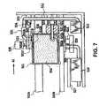
- the printing head 502moves from the home position to the ink-supplying position in the direction of the arrow A1. If the printing head 502 arrives at the ink-supplying position, as shown in Fig. 7 , both the first and second cap members 524, 525 are raised, and then the nozzle portion 502A of the printing head 502 is capped by the first cap member 524. As a result, the cap member 524 seals the ink eject port of the nozzle portion 502A. At this time, the seal member 523 opens the through hole 521A by its relative movement with reference to the projection member 521 while keeping the ink inlet 501A in a closed state.
- the through hole 521Aforms an ink-supplying system between the sub tank 501 and the main tank by communicating the through hole 521A with the inside of the sub tank 501. Also, the seal member 532 closes the air-communicating port 501C and then connects the opening 532A to the suction port 501B to form an air suction system between the opening 532A and the suction pump 513.
- the gas-permeable member 505lies in the suction system.
- the supply of inkis automatically stopped because liquid such as ink cannot pass through the gas-permeable member 505.
- the supply of inkis concurrently performed on the ink-storage portions 501C, 501M, 501Y, and 501B, so that the supply of ink to each of the reserve ink tanks 20Y, 20M, 20C, and 20K is stopped by the gas-permeable member 505 in order of being filled up with ink.
- the printing apparatusAfter completing such an action of supplying ink, the printing apparatus is recovered to its original state as shown Fig. 6 or Fig. 4 by returning the printing head 502 to its home position or its position of starting the printing movement.
- the blade 536touches the bottom surface of the seal member 532 in accordance with the movement of the sub tank 501, as indicated by a two-short dashed line in Fig. 4 , so that the blade 536 wipes the bottom surface of the seal member 532 including the gas-permeable member 505 while the arm member 531 is turned up and down.
- the wiping operationremoves undesired materials such as thickened ink being adhered on the gas-permeable member 505, the opening 532, and the seal member 532, so that they can be kept in good conditions.
- Figs. 8 to 10are explanatory view for illustrating a second preferred embodiment of the present invention. An explanation for the some reference numerals as those of the first preferred embodiment will be omitted in the following description.
- the reference numeral 1521denotes a projected hollow member formed on the main body's side of the printing apparatus.
- a seal member 1523is coaxially fitted over an outer peripheral surface of the projected member 1521 so that the seal member 1523 is able to slide over the surface.
- a spring 1522is also fitted over the outer peripheral surface of the projected member 1521 so that it pushes the seal member 1523 leftward.
- a through hole 1521Ais formed on the peripheral surface of the projected member 1521, which is opened or closed by the seal member 1523. The tip of the projected member 1521 is being closed, while the base thereof is connected to a main tank (not shown). A gas-permeable member is placed in a opening of the seal member 1523.
- the reference numeral 1531denotes a seal member which is able to close the air-communicating port 501C of the sub tank 501.
- the seal member 1531is mounted on the tip portion of an arm member 1532.
- a base portion of the arm member 1532is supported by a support member 1533 so as to turn up and down and downwardly spring-loaded by a spring 1534, where the support member 1533 is placed on the side of the main body of the printing apparatus.
- the reference numeral 1535denotes a stopper member that regulates the position of downward movement of the arm member 1532.
- the reference numeral 1536denotes a projection portion formed on the sub tank 501. The projection portion 1536 actuates the arm member 1532 up and down in response to the location of the sub tank 501 being moved. As shown in the figure, the arm member 1532 has a recess 1532A in which the projection portion 1536 can be slipped.
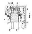
- the seal member 1523closes the suction port 501B when the printing head 502 is located at its home position as shown in Fig. 9 . If the printing head 502 arrives at the ink-supplying position, as shown in Fig. 10 , an air suction system is formed through the gas-permeating member 505 and the through hole 1521A, while the air-communicating port 501C is closed by the seal member 1531. In this case, by the way, the longitudinal length of the protruded member 1521 is adjusted so that it is not inserted into the sub tank 501.
- Fig. 11is an explanatory view for illustrating a third preferred embodiment of the present invention.
- the length of th protruded member 1521 as described in the second preferred embodimentis comparatively long enough to insert its tip into the sub tank 501 at the time of supplying ink.
- the gas-permeable member 505is placed in opening of the through hole 1521A of the protruded member 1521.
- an air suction systemis formed through the gas-permeable member 505 when the tip of the protruded member 1521 is inserted into the sub tank 501.
- the shape or characteristics of the gas-permeable member 505is altered according to the capacity of the sub tank 501 or the type of ink to be retained in the sub tank 501.
- a porous bodyas a gas-permeable member 505 and make a change in its own characteristics and shape so as to alter the negative pressure to be caused in the sub tank 501 according to the capacity of the sub tank 501 having the gas-permeable member 505 or the type of ink to be retained in the sub tank 501.
- the thickness of the gas-permeable member 505is modified so as to have a different pore size or a thickness thereof.
- the rate of supplying ink to each sub tank 501can be adjusted by making a change in the negative pressure in the sub tank 501. If the sub tank 501 stores ink having a large flow resistance or having a large ink capacity is used, a gas-permeable member 505 may be selected so as to establish large negative pressure in the sub tank 501. Therefore, the supply of ink can be effectively performed on a plurality of sub tanks 501.
- the characteristics of the gas-permeable member 505can be modified so as to have a different pore size or a thickness of the gas-permeable member 505.
- the physical properties (e.g., air permeability) of the gas-permeable member 505may be also modified.
- the gas-permeable membermay be of having the function of separating gas and liquid, so that various kinds of materials may be used in accordance with the types of ink or usage patterns.
- the gas-permeable membermay be an gas-permeable film made of a tetrafluoride ethylene resin or other porous resin materials.
- a tetrafluoride ethylene resinor other porous resin materials.
- another porous materialmade of a natural or synthesis material such as knitted fabric, woven fabric, non-woven fabric, net, felt, porcelain, unglazed pottery, earthenware, or ceramic.
- the gas-permeable membermay be a mechanical valve that is closed when gas comes and opened when the flow of liquid comes.
- the ink tank of the present inventionis not limited to the one that moves together with the printing head in the serial-scan type printing apparatus. It is also possible to fix the ink tank in place.
Landscapes
- Ink Jet (AREA)
- Nozzles (AREA)
- Coating Apparatus (AREA)
- Particle Formation And Scattering Control In Inkjet Printers (AREA)
Abstract
Description
- The present invention relates to an ink-jet printing apparatus.
- Heretofore, a serial-scanning type printing apparatus has been known as an example of the ink-jet printing apparatus. This kind of the printing apparatus exchangeably carries a printing head as a printing means and an ink tank as an ink container on the carriage which is capable of movement in the direction of main-scanning perpendicular to the direction of sub-scanning (i.e. , the direction of moving a printing medium such as a piece of paper). As for this kind of the printing system, images are sequentially printed on a printing medium by repeating the movement of the carriage on which the printing head and the ink tank are mounted in the direction of main-scanning and the movement of the printing medium in the direction of sub-scanning.
- The serial-scanning type printing apparatus is able to print an image on a large sized printing medium (e.g., A1, A0 size) by enlarging the migration width of the carriage. In this case, however, the ink storage capacity of the ink tank should be increased for using a great volume of ink to print an image on the surface of a large-sized printing, so that the whole weight of the carriage is increased in proportion to the capacity of the ink. In addition, an inertial force in the movement of the carriage is also proportionally increased. For moving the carriage at a high speed against the inertial force, there is the need for installing a driving motor with a large amount of electric power for driving the carriage in high power, resulting in the problem of increasing the price of the printing apparatus in its entirety. In addition, as the total weight of the carriage is increased, there is another problem that the printing apparatus oscillates greatly as a whole by the counterforce contrary to the force for deaccelerating the carriage to zero against the inertial force when the carriage returns at a returning point of its reciprocating motion in the main-scanning direction. Therefore, it was difficult for speeding up the travel speed of the carriage.
- For reducing the weight of the carriage, on the other hand, the capacity of the ink tank may be lessened. In this case, however, the frequency of replacing the ink tank rises and thus there is a high possibility of replacing the ink tank with the new one in the middle of the printing movement.
- One of the solutions to solve the problem about such a replacement of the ink tank is proposed in
EP0803362 A2 . US4967207A discloses an ink jet apparatus comprising a sub tank provided with an ink-jet printing head, a negative pressure loading means and ink supply means.- It is an object of the present invention to provide an ink-jet printing apparatus, where ink can be reliably supplied to the ink tank by a simplified configuration of an ink passage to achieve both the size and weight reductions of the printing apparatus and to increase the reliability thereof.
- According to the present invention, there is provided an ink- jet printing apparatus for printing an image on a printing medium employing an ink-jet printing head capable of ejecting ink supplied from an ink tank, comprising the features of claim 1.
- The present invention is configured such that the supply of ink under suction can be automatically stopped using the function of a gas-permeable member, so that the supply of ink to the ink tank can be performed by a simple structure with reliability. This offers an advantage of being able to achieve both the size and weight reductions of the printing apparatus and an improved reliability thereof.
- The present invention may be configured such that a porous material with an oil repellent finish is used as a gas-permeable member to be functioned as gas-liquid separating means. The gas-permeable member repels ink enough. This offers an advantage of being able to achieve the supply of ink smoothly over an extended period of time with reliability in addition to improve the durability of the gas-permeable member.
- The present invention is configured such that the gas-liquid separating means is not connected to the inside of the ink tank except when the supply of ink is performed. This offers an advantage of being able to prevent that the performance of the gas-liquid separate means is decreased by exposing the gas-liquid separate means to ink for a long time.
- The above and other objects, effects, features and advantages of the present invention will become more apparent from the following description taken in conjunction with the accompanying drawings.
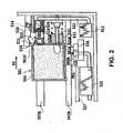
Fig. 1 is a cross sectional view of a main part for illustrating an example outside the scope of the present invention, but useful for understanding the present invention;Fig. 2 is an explanation view for illustrating the condition of the printing head ofFig. 1 being capped;Fig. 3 is an explanation view for illustrating the condition of supplying ink to the sub-tank shown inFig. 1 ;Fig. 4 is a cross sectional view of a main part for illustrating a first embodiment of the present invention:Fig. 5 is a side view of the main part shown in Fig.- 4;
Fig. 6 is an explanation view for illustrating the condition of the printing head ofFig. 4 being capped; Fig. 7 is an explanation view for illustrating the condition of supplying ink to the sub-tank shown inFig. 4 ;Fig. 8 is a cross sectional view of a main part for illustrating a second embodiment of the present invention:Fig. 9 is an explanation view for illustrating the condition of the printing head ofFig. 8 being capped;Fig. 10 is an explanation view for illustrating the condition of supplying ink to the sub-tank shown inFig. 8 ; andFig. 11 is a cross sectional view of the main part for illustrating a thrid embodiment of the present invention;Figs. 1 to 3 illustrate an example outside the scope of the present invention.- In
Fig. 1 , thereference numeral 501 denotes a sub ink tank (hereinafter, also referred to as a sub-tank); and 502 denotes a printing head that is able to eject ink from anozzle portion 502, where the ink is supplied from thesub-tank 501, which are configured to move alongguide shafts sub-tank 501 comprises anink inlet 501A, asuction port 501B, an air-communicatingport 501C, and a communicating port (not shown) for communicating with theprinting head 502. In addition, anink absorber 504 is provided for retaining ink by absorption and installed in thesub-tank 501. Thesuction port 501B is conical in cross section with a gradual increase in diameter outwardly. A gas-permeable member 505 is placed on the external side of thesuction port 501B. The gas-permeable member 505 is provided as a means for separating gas and liquid. The gas-permeable member 505 may be of a thin-sheet type and made of a tetrafluoride ethylene resin or other porous resin materials. - Furthermore, a hollow-
projection portion 507 formed on the outside of thesuction port 501B. The hollow-projection portion 507 can be inserted into acap member 506 on the side of a main body of the printing apparatus. In addition, aseal member 508 fits over a small-diameter portion 507A on the tip side of theprojection portion 507 so that theseal member 508 is able to slide over a small-diameter portion 507A. On the other hand, aspring 509 that pushes theseal member 508 rightward is fit over a large-diameter portion 507B on the base side of theprojection portion 507. A throughhole 510 is formed on the peripheral surface of the small-diameter portion 507A, which is opened or closed by theseal member 508. The tip of the small-diameter portion 507A is closed by acap member 511. Thecap member 511 is also configured to function as a stopper that prevents theseal member 508 from becoming disengage. Thecap member 506 is connected to asuction pump 513 through asuction conduit 512. - The
reference numeral 521 denotes a hollow-projection member formed on the side of the main body of the printing apparatus. Aseal member 523 is able to fit over the outer peripheral surface of theprojection member 521 and pushed leftward by the force of aspring 522 so as to slide thereon. A throughhole 521A is formed on the peripheral surface of theprotrusion member 521, which is opened or closed by theseal member 523. The tip of theprotrusion member 521 is formed as a closed end, while the base side thereof is connected to a main ink tank (hereinafter, also referred to as a main-tank). - The
reference numerals cap members second cap member 525 is connected to a waste ink tank (not shown) through asuction pump 526. Thereference numeral 527 denotes a platen for guiding a printing medium to a printing position where an image formation is performed by theprinting head 502. The printing medium is fed by a feeding mechanism (not shown) in the sub-scanning direction that crosses with the main-scanning direction. Every part of the image is formed successively on the printing medium by repeating the printing movement of the printing head in the main-scanning direction while ejecting ink and the feeding movement of the printing medium in the sub-scanning direction. - The
reference numeral 531 denotes a seal member which is able to close the gas-communicatingport 501C of thesub-tank 501. Theseal member 531 is mounted on the tip portion of anarm member 532. A base portion of thearm member 532 is by asupport member 533 so as to turn up and down and downwardly spring-loaded by aspring 534, where thesupport member 533 is placed on the side of the main body of the printing apparatus. Thereference numeral 535 denotes a stopper member that regulates the position of downward movement of thearm member 532. The reference numerals 536 denotes a projection portion formed on the main-tank 501. Theprojection portion 536 actuates thearm member 532 up and down in response to the location of the sub-tank 501 being moved. Thearm member 532 has arecess 532A in which theprojection portion 536 can be slipped. - - During the printing movement, the
printing head 502 is initially located in the moving range on the left side from a home position (seeFig. 2 ) and then moves in the direction of the arrow A1 or A2 while printing an image by ejecting ink. - If the
printing head 502 reaches to the home position, both the first and second cap members. 524, 525 are raised as shown inFig. 2 . As a result, thenozzle portion 502A of theprinting head 502 is capped by thesecond cap member 525. At this time, theseal member 523 closes theink inlet 501A while keeping the throughhole 521A of theprojection member 513 in a closed state. In addition, theseal member 508 closes an opening of thecap member 506 while keeping the throughhole 510 of theprojection portion 507 in a closed state. Theprinting head 502 being located on the home position is subjected to the recovery procedure in which theprinting head 502 discharges ink that is not used in the process of printing an image, so that the condition of ejecting ink can be kept in a favorable condition. The recovery procedure includes the process of sucking and draining ink and the process of ejecting the ink. The process of sucking and draining ink comprises the step of forcing ink out of the ink eject port of thenozzle portion 502A under suction by causing negative pressure in the second cap member by thesuction pump 526. The process of ejecting ink comprises the step of ejecting ink from the ink eject port of thenozzle portion 502A into thesecond cap member 525. - During the action of supplying ink, as shown in
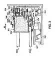
Fig.3 , theprinting head 502 moves from the home position to the ink-supplying position in the direction of the arrow A1. If theprinting head 502 arrives at the ink-supplying position, as shown inFig. 3 , both the first andsecond cap members nozzle portion 502A of theprinting head 502 is capped by thefirst cap member 524. As a result, thecap member 524 seals the ink eject port of thenozzle portion 502A. At this time, as shown inFig. 2 , theseal member 523 opens the throughhole 521A by its relative movement with reference to theprojection member 521 while keeping theink inlet 501A in a closed state. The throughhole 521A forms an ink-supplying system between the sub-tank 501 and the main-tank by communicating the throughhole 521A with the inside of the sub-tank 501. In addition, the seal member508 opens throughhole 510 by its relative movement with reference to theprojection portion 507 while keeping the opening of thecap member 506 in a closed state. Furthermore, a suction system between thesuction port 501B and thesuction pump 513 is formed by communicating the throughhole 510 with the inside of thecap member 506. The gas-permeable member 505 lies in the suction system. In addition, theseal member 531 closes the air-communicatingport 501C by actuating thearm member 532 upward at first and then actuating it downward. - On the occasion of the supply of ink, air in the sub-tank 501 is aspirated by the
suction pump 513 through the gas-permeable member 505 to discharge the air into a liquid waste container (not shown), causing negative pressure in the sub-tank 501. Thus, ink in the main-tank is introduced into the sub-tank 501 under suction by an effect of the negative pressure. The ink flowing in the sub-tank 501 permeates theink absorber 504, so that a level of ink rises as the permeation of ink proceeds. The rising rate of the level of ink depends on the suction force of thesuction pump 513, so that it is adjusted to an appropriate rate corresponding to the degree of actuating thesuction pump 513. If the level of ink reaches to the gas-permeable member 505, the supply of ink is automatically stopped because liquid such as ink cannot pass through the gas-permeable member 505. - After completing such an action of absorbing ink, the printing apparatus to its original state as shown
Fig. 2 orFig. 1 by returning theprinting head 502 to its home position or its position of starting the printing movement. - By the way, the gas-
permeable member 505 and theink absorber 504 are separated by the space of thesuction port 501B, so that they do not contact to each other. If the gas-permeable member touches ink for a long time, the functions of the gas-permeable member might decrease. In this embodiment, however, there is the space between the gas-permeable member 505 and theink absorber 504, so that the gas-permeable member 505 does not touch to ink except when the supply of ink is performed. Consequently, the functional decline of the gas-permeable member can be prevented. - Furthermore, an inner surface of the
suction port 501B is inclined, so that the ink that has arrived in thesuction port 501B at the time of supplying ink is promptly exhausted along the inner surface of thesuction port 501B after completing the action of supplying ink. Therefore, the duration of contact between the gas-permeable member 505 and the ink can be minimized inescapably. In this example, an inner bottom surface of thesuction port 501B is inclined downward on the right inFig. 1 , so that ink tends to be easily discharged to the outside of the sub-tank 501. If the inner bottom surface of thesuction port 501B is inclined downward on the left inFig. 1 , ink tends to be easily discharged to the inner side of the sub-tank 501. Ink in thesuction port 501B can be smoothly discharged therefrom when the inner side of thesuction port 501B is subjected to water-repellent finishing. - As the through
hole 510 is closed by theseal member 508 except when the suction of ink is performed, furthermore, the thickening of ink in the main-tank 501 in addition to the depositing of ink on thesuction port 501B and the gas-permeable member 505 can be prevented. Figs. 4 to 7 are explanatory views for illustrating a first preferred embodiment of the present invention.- In
Fig. 4 , thereference numeral 501 denotes a sub ink tank (hereinafter, also referred to as a sub tank) that is able to store ink, and 502 denotes a printing head that is able to receive the ink stored in thesub tank 501 and eject the ink from itsnozzle portion 502A. Thesesub tank 501 and theprinting head 502 is moved alongguide shafts sub tank 501 and theprinting head 502 can be removably installed on a carriage (not shown) guided byguide shafts sub tank 501 has anink inlet 501A, asuction port 501B, an air-communicatingport 501C, and an ink-supplying port (not shown) that communicates with theprinting head 502. In addition, anink absorber 504 is placed in thesub tank 501 to retain ink under suction. - According to the present embodiment, the
sub tank 501 comprises four different ink-storage portions. That is, there are an ink-storage portion 501C for cyan ink, an ink-storage portion 501M for magenta ink, an ink-storage portion 501Y for yellow ink, and an ink-storage portion 501B for black ink. Furthermore, each ink-storage portion has anink inlet 501A, asuction port 501B, an air-communicatingport 501C, and an ink-supplying port that communicates with theprinting head 502. Considering that the black ink is used frequently in comparison with those of the others, the capacity of the ink-storage portion 501B for black ink is larger than those of the others. Thenozzles 502A of theprinting head 502 is configured so as to be fit the respective ink-storage portions sub tank 501 and theprinting head 502 may be configured to be coupled together to form an ink-jet cartridge. Alternatively, thesub tank 501 and theprinting head 502 may be configured to be provided as separated structures for the respective ink colors. - Referring again to
Fig. 4 , thereference numeral 521 denotes a projected hollow member formed on the main body' s side of the printing apparatus. In addition, aseal member 523 is coaxially fitted over an outer peripheral surface of the projectedmember 521 so that theseal member 523 is able to slide over the surface. Furthermore, aspring 522 is also fitted over the outer peripheral surface of the projectedportion 521 so that it pushes theseal member 523 leftward. A throughhole 521A is formed on the peripheral surface of the projectedmember 521, which is opened or closed by theseal member 523. The tip of the projectedmember 521 is being closed, while the base thereof is connected to a main ink tank (hereinafter also referred to as a main tank) (not shown). - The
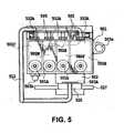
reference numeral 531 denotes an arm member that is supported by asupport member 533 on the main body's side of the printing apparatus so as to turn up and down and downwardly spring-loaded by aspring 534. Aseal member 532 that is coaxially provided on thearm member 531 has anopening 532A and aseal portion 532B. Theopening 532A is able to communicate with thesuction port 501B and connected to a suction pump through asuction tube 512. On the other hand, theseal portion 532B is able to close and open thesuction port 501B and the air-communicatingport 501C. In this embodiment, as shown inFig. 5 , theopenings 532A adapted to therespective suction ports 501B of the ink-storage portions suction tube 521 and then connected to acommon suction pump 513. Furthermore, a gas-permeable member 505 is placed in theopening 532A, which permeates gas but ink. The gas-permeable member 505 may be of a thin sheet type and made of a tetrafluoride ethylene resin or other porous resin materials. On the other hand, ablade 536 is provided on the side of thesub tank 501. Theblade 536 is ale to wipe the bottom surface of theseal member 532 including the gas-permeable member 505. Furthermore, thereference numeral 535 denotes a stopper member that regulates the position of upward movement of thearm member 531. - The
reference numerals cap members second cap member 525 is connected to a waste ink tank (not shown) through asuction pump 526. Thereference numeral 527 denotes a platen for guiding a printing medium to a printing position where an image formation is performed by theprinting head 502. The printing medium is carried by a feeding mechanism (not shown) in the sub-scanning direction that crosses with the main-scanning direction (the direction of the arrow A1 or A2). Every part of the image is formed successively on the printing medium by repeating the printing movement of theprinting head 502 in the main-scanning direction while ejecting ink and the feeding movement of the printing medium in the sub-scanning direction. - During the printing movement, the
printing head 502 is initially located in the moving range on the left side from its home position (seeFig. 6 ) and then moves in the direction of the arrow A1 or A2 while printing an image by ejecting ink. - If the
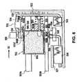
printing head 502 reaches to the home position, both the first andsecond cap members nozzle portion 502A of theprinting head 502 is capped by thesecond cap member 525. At this time, theseal member 523 closes theink inlet 501A while keeping the throughhole 521A of the projectedmember 513 in a closed state. In addition, theseal member 532 closes thesuction port 501B. Accordingly, an increase in the viscosity of ink in thesub tank 501 can be prevented by closing theink inlet 501A and thesuction port 501B. In addition, the gas-permeable member 505 is located rightward inFig. 6 at a location some distance from thesuction port 501B, so that the contact between the gas-permeable member 505 and the ink in thesub tank 501 can be avoided. Consequently, the gas-permeable member 505 can be remained intact by avoiding the long-term contact with ink. Theprinting head 502 being located on the home position is subjected to the recovery procedure in which theprinting head 502 discharges ink that is not used in the process of printing an image, so that the condition of ejecting ink can be kept in a favorable condition. The recovery procedure includes the process of sucking and draining ink and the process of ejecting the ink. The process of sucking and draining ink comprises the step for forcing ink out of the ink eject port of thenozzle portion 502A under suction by causing negative pressure in thesecond cap 525 member by thesuction pump 526. The process of ejecting ink comprises the step for ejecting ink from the ink eject port of thenozzle portion 502A into thesecond cap member 525. - During the action of supplying ink, as shown in
Fig. 7 , theprinting head 502 moves from the home position to the ink-supplying position in the direction of the arrow A1. If theprinting head 502 arrives at the ink-supplying position, as shown inFig. 7 , both the first andsecond cap members nozzle portion 502A of theprinting head 502 is capped by thefirst cap member 524. As a result, thecap member 524 seals the ink eject port of thenozzle portion 502A. At this time, theseal member 523 opens the throughhole 521A by its relative movement with reference to theprojection member 521 while keeping theink inlet 501A in a closed state. The throughhole 521A forms an ink-supplying system between thesub tank 501 and the main tank by communicating the throughhole 521A with the inside of thesub tank 501. Also, theseal member 532 closes the air-communicatingport 501C and then connects theopening 532A to thesuction port 501B to form an air suction system between theopening 532A and thesuction pump 513. The gas-permeable member 505 lies in the suction system. - On the occasion of the supply of ink, air in the
sub tank 501 is aspirated by thesuction pump 513 through the gas-permeable member 505 to discharge the air into a liquid waste container (not shown), causing negative pressure in thesub tank 501. Thus, ink in the main tank is introduced into thesub tank 501 under suction by an effect of the negative pressure. The ink flowing into thesub tank 501 permeates theink absorber 504, so that a level of ink rises as the permeation of ink proceeds. The rising rate of the level of ink depends on the suction force of thesuction pump 513, so that it is adjusted to an appropriate rate corresponding to the degree of actuating thesuction pump 513. If the level of ink reaches to the gas-permeable member 505, the supply of ink is automatically stopped because liquid such as ink cannot pass through the gas-permeable member 505. In addition, the supply of ink is concurrently performed on the ink-storage portions permeable member 505 in order of being filled up with ink. - After completing such an action of supplying ink, the printing apparatus is recovered to its original state as shown
Fig. 6 orFig. 4 by returning theprinting head 502 to its home position or its position of starting the printing movement. - By the way, the
blade 536 touches the bottom surface of theseal member 532 in accordance with the movement of thesub tank 501, as indicated by a two-short dashed line inFig. 4 , so that theblade 536 wipes the bottom surface of theseal member 532 including the gas-permeable member 505 while thearm member 531 is turned up and down. The wiping operation removes undesired materials such as thickened ink being adhered on the gas-permeable member 505, theopening 532, and theseal member 532, so that they can be kept in good conditions. Figs. 8 to 10 are explanatory view for illustrating a second preferred embodiment of the present invention. An explanation for the some reference numerals as those of the first preferred embodiment will be omitted in the following description.- In these figures, the
reference numeral 1521 denotes a projected hollow member formed on the main body's side of the printing apparatus. In addition, aseal member 1523 is coaxially fitted over an outer peripheral surface of the projectedmember 1521 so that theseal member 1523 is able to slide over the surface. Furthermore, aspring 1522 is also fitted over the outer peripheral surface of the projectedmember 1521 so that it pushes theseal member 1523 leftward. A throughhole 1521A is formed on the peripheral surface of the projectedmember 1521, which is opened or closed by theseal member 1523. The tip of the projectedmember 1521 is being closed, while the base thereof is connected to a main tank (not shown). A gas-permeable member is placed in a opening of theseal member 1523. - The
reference numeral 1531 denotes a seal member which is able to close the air-communicatingport 501C of thesub tank 501. Theseal member 1531 is mounted on the tip portion of anarm member 1532. A base portion of thearm member 1532 is supported by asupport member 1533 so as to turn up and down and downwardly spring-loaded by aspring 1534, where thesupport member 1533 is placed on the side of the main body of the printing apparatus. Thereference numeral 1535 denotes a stopper member that regulates the position of downward movement of thearm member 1532. Thereference numeral 1536 denotes a projection portion formed on thesub tank 501. Theprojection portion 1536 actuates thearm member 1532 up and down in response to the location of thesub tank 501 being moved. As shown in the figure, thearm member 1532 has arecess 1532A in which theprojection portion 1536 can be slipped. - In the present embodiment, the
seal member 1523 closes thesuction port 501B when theprinting head 502 is located at its home position as shown inFig. 9 . If theprinting head 502 arrives at the ink-supplying position, as shown inFig. 10 , an air suction system is formed through the gas-permeatingmember 505 and the throughhole 1521A, while the air-communicatingport 501C is closed by theseal member 1531. In this case, by the way, the longitudinal length of the protrudedmember 1521 is adjusted so that it is not inserted into thesub tank 501. Fig. 11 is an explanatory view for illustrating a third preferred embodiment of the present invention.- In this embodiment, the length of th protruded
member 1521 as described in the second preferred embodiment is comparatively long enough to insert its tip into thesub tank 501 at the time of supplying ink. In addition, the gas-permeable member 505 is placed in opening of the throughhole 1521A of the protrudedmember 1521. Thus, an air suction system is formed through the gas-permeable member 505 when the tip of the protrudedmember 1521 is inserted into thesub tank 501. - In this embodiment, the shape or characteristics of the gas-
permeable member 505 is altered according to the capacity of thesub tank 501 or the type of ink to be retained in thesub tank 501. - For example, it is possible to provide a porous body as a gas-
permeable member 505 and make a change in its own characteristics and shape so as to alter the negative pressure to be caused in thesub tank 501 according to the capacity of thesub tank 501 having the gas-permeable member 505 or the type of ink to be retained in thesub tank 501. Concretely, the thickness of the gas-permeable member 505 is modified so as to have a different pore size or a thickness thereof. - Accordingly, the rate of supplying ink to each
sub tank 501 can be adjusted by making a change in the negative pressure in thesub tank 501. If thesub tank 501 stores ink having a large flow resistance or having a large ink capacity is used, a gas-permeable member 505 may be selected so as to establish large negative pressure in thesub tank 501. Therefore, the supply of ink can be effectively performed on a plurality ofsub tanks 501. - Concretely, the characteristics of the gas-
permeable member 505 can be modified so as to have a different pore size or a thickness of the gas-permeable member 505. In addition, the physical properties (e.g., air permeability) of the gas-permeable member 505 may be also modified. - The gas-permeable member may be of having the function of separating gas and liquid, so that various kinds of materials may be used in accordance with the types of ink or usage patterns. The gas-permeable member may be an gas-permeable film made of a tetrafluoride ethylene resin or other porous resin materials. However, it is also possible to use another porous material made of a natural or synthesis material such as knitted fabric, woven fabric, non-woven fabric, net, felt, porcelain, unglazed pottery, earthenware, or ceramic. Furthermore, the gas-permeable member may be a mechanical valve that is closed when gas comes and opened when the flow of liquid comes.
- The ink tank of the present invention is not limited to the one that moves together with the printing head in the serial-scan type printing apparatus. It is also possible to fix the ink tank in place.
- The present invention has been described in detail by way of example only, with respect to various embodiments, and it will now be apparent from the foregoing to those skilled in the art that changes and modifications without departing from the scope of the appended claims.
Claims (5)
- An ink-jet printing apparatus for printing an image on a printing medium employing an ink-jet printing head (502) capable of ejecting ink supplied from a main ink tank, the ink-jet printing apparatus comprising:a sub tank (501) provided with the ink-jet printing head (502), the main ink tank containing ink to be supplied to the sub tank (501), the ink-jet printing head (502) being capable of ejecting ink supplied from the sub tank (501);a negative-pressure loading means (513) having a negative-pressure loading passage (512) for introducing negative pressure into the sub tank (501); andan ink-supplying means having an ink-supplying passage (521) for supplying ink into the sub tank (501) from the main ink tank using the negative pressure in the sub tank (501), whereinthe negative-pressure loading passage (512) and the ink-supplying passage (521) are configured to connect to the sub tank (501) when the supply of ink from the main ink tank to the sub tank (501) is performed, and configured to be released from the sub tank (501) when the supply of ink from the main ink tank to the sub tank (501) is finished, anda gas-liquid separating means (505) which permits gas to pass but inhibits ink from passing is provided in the negative-pressure loading passage (512).
- An ink-jet printing apparatus as claimed in Claim 1, wherein
the ink-jet printing head (502) having the sub tank (501) is mounted on a carriage, and
the negative-pressure loading passage (512) and the ink-supplying passage (521) are connected to the sub tank (501) when the carriage moves closer to the negative-pressure loading passage (512) and the ink-supplying passage (521), and are released from the sub tank (501) when the carriage moves away from the negative-pressure loading passage (512) and the ink-supplying passage (521). - An ink-jet printing apparatus as claimed in Claim 1 or 2, wherein the gas-liquid separating means (505) is provided with a member made of a porous material with an oil repellent finish.
- An ink-jet printing apparatus as claimed in Claim 1 or 2, wherein the gas-liquid separating means (505) is an gas-permeable membrane made of a material selected from a tetrafluoride ethylene resin, a polyolefin resin, and other porous resin materials, which is subjected to an oil-repellent finish.
- An ink-jet printing apparatus as claimed in Claim 1 or 2, wherein the gas-liquid separating means (505) is a gas-permeable membrane made of a material selected from porcelain, unglazed pottery, ceramic and other porous materials, which is subjected to an oil-repellent finish.
Applications Claiming Priority (6)
| Application Number | Priority Date | Filing Date | Title |
|---|---|---|---|
| JP15306399AJP3347689B2 (en) | 1999-05-31 | 1999-05-31 | Ink tank, inkjet cartridge, and inkjet recording device |
| JP15306099AJP3347688B2 (en) | 1999-05-31 | 1999-05-31 | Ink tank, inkjet cartridge, and inkjet recording device |
| JP15306499AJP3347690B2 (en) | 1999-05-31 | 1999-05-31 | Ink jet recording device, ink supply device, and ink supply method |
| JP15306299AJP3323831B2 (en) | 1999-05-31 | 1999-05-31 | Ink tank and recording device |
| JP2000117063AJP2001301194A (en) | 2000-04-18 | 2000-04-18 | Ink tank, inkjet cartridge, ink supply device, inkjet recording device, and ink supply method |
| EP00304547AEP1057644B1 (en) | 1999-05-31 | 2000-05-30 | Ink tank and ink-jet printing apparatus |
Related Parent Applications (2)
| Application Number | Title | Priority Date | Filing Date |
|---|---|---|---|
| EP00304547.3Division | 2000-05-30 | ||
| EP00304547ADivisionEP1057644B1 (en) | 1999-05-31 | 2000-05-30 | Ink tank and ink-jet printing apparatus |
Publications (3)
| Publication Number | Publication Date |
|---|---|
| EP1920933A2 EP1920933A2 (en) | 2008-05-14 |
| EP1920933A3 EP1920933A3 (en) | 2009-05-13 |
| EP1920933B1true EP1920933B1 (en) | 2011-02-16 |
Family
ID=27528009
Family Applications (3)
| Application Number | Title | Priority Date | Filing Date |
|---|---|---|---|
| EP07076047AExpired - LifetimeEP1920933B1 (en) | 1999-05-31 | 2000-05-30 | Ink-jet printing apparatus |
| EP00304547AExpired - LifetimeEP1057644B1 (en) | 1999-05-31 | 2000-05-30 | Ink tank and ink-jet printing apparatus |
| EP07076048AExpired - LifetimeEP1920934B1 (en) | 1999-05-31 | 2000-05-30 | Ink tank, ink-jet print head, and ink-jet cartridge |
Family Applications After (2)
| Application Number | Title | Priority Date | Filing Date |
|---|---|---|---|
| EP00304547AExpired - LifetimeEP1057644B1 (en) | 1999-05-31 | 2000-05-30 | Ink tank and ink-jet printing apparatus |
| EP07076048AExpired - LifetimeEP1920934B1 (en) | 1999-05-31 | 2000-05-30 | Ink tank, ink-jet print head, and ink-jet cartridge |
Country Status (9)
| Country | Link |
|---|---|
| US (2) | US6540321B1 (en) |
| EP (3) | EP1920933B1 (en) |
| KR (1) | KR100341254B1 (en) |
| CN (1) | CN1150090C (en) |
| AT (3) | ATE498492T1 (en) |
| AU (1) | AU768376B2 (en) |
| CA (1) | CA2310181C (en) |
| DE (3) | DE60045647D1 (en) |
| TW (1) | TW518285B (en) |
Families Citing this family (120)
| Publication number | Priority date | Publication date | Assignee | Title |
|---|---|---|---|---|
| DE60040245D1 (en)* | 2000-01-05 | 2008-10-23 | Hewlett Packard Co | Inkjet pen with a two-part lid |
| US6629758B2 (en)* | 2000-04-19 | 2003-10-07 | Canon Kabushiki Kaisha | Joint device, ink jet recording apparatus having the same, and ink supplying device and method |
| JP3416614B2 (en)* | 2000-04-26 | 2003-06-16 | キヤノン株式会社 | Ink jet recording device |
| JP2002273918A (en)* | 2001-03-21 | 2002-09-25 | Canon Inc | Printers and digital cameras |
| US6846072B2 (en)* | 2000-11-29 | 2005-01-25 | Canon Kabushiki Kaisha | Ink, ink-jet ink, ink-tank, ink-jet cartridge, ink supply device, method for introducing ink to ink tank and image recording device |
| JP3787520B2 (en) | 2000-12-28 | 2006-06-21 | キヤノン株式会社 | Structure manufacturing method and manufacturing apparatus therefor |
| DE60227731D1 (en)* | 2001-02-09 | 2008-09-04 | Seiko Epson Corp | Ink jet recording device, control and Tintennachfüllsverfahren performed in the device, ink supply system in the device, and management methods of the ink supplied by the system |
| CN101177069B (en)* | 2001-02-09 | 2012-06-13 | 精工爱普生株式会社 | Ink supply system and method of managing ink amount supplied by the system |
| US7150519B2 (en)* | 2001-02-23 | 2006-12-19 | Canon Kabushiki Kaisha | Ink jet recording apparatus |
| US6929356B2 (en) | 2001-03-21 | 2005-08-16 | Canon Kabushiki Kaisha | Container of consumable supplies for a printer and printer utilizing the container |
| JP3787522B2 (en)* | 2001-12-28 | 2006-06-21 | キヤノン株式会社 | Structure, liquid tank, ink jet recording apparatus manufacturing method, and ink jet recording apparatus |
| AUPS049202A0 (en)* | 2002-02-13 | 2002-03-07 | Silverbrook Research Pty. Ltd. | Methods and systems (ap52) |
| JP3658373B2 (en) | 2002-02-22 | 2005-06-08 | キヤノン株式会社 | Liquid storage container, ink jet cartridge, and ink jet recording apparatus |
| JP2003291367A (en) | 2002-04-02 | 2003-10-14 | Sony Corp | Device for displaying remaining amount of liquid |
| US6652080B2 (en)* | 2002-04-30 | 2003-11-25 | Hewlett-Packard Development Company, Lp. | Re-circulating fluid delivery system |
| DE60335587D1 (en) | 2002-06-21 | 2011-02-17 | Canon Kk | inkjet |
| JP4371725B2 (en)* | 2002-07-16 | 2009-11-25 | キヤノン株式会社 | Inkjet recording device |
| US6929341B2 (en) | 2002-08-05 | 2005-08-16 | Canon Kabushiki Kaisha | Ink jet recording apparatus, ink container, and ink cartridge |
| ATE446196T1 (en)* | 2002-08-16 | 2009-11-15 | Oce Tech Bv | INK SUPPLY DEVICE FOR AN INKJET PRINTER |
| CN1261304C (en)* | 2002-09-30 | 2006-06-28 | 佳能株式会社 | Ink supply system and its filling and adding container, ink-jet recording device and cartriage |
| JP2004237723A (en)* | 2003-01-17 | 2004-08-26 | Canon Inc | INK JET PRINTING APPARATUS, IMAGING APPARATUS, AND INK SUPPLY METHOD IN THE APPARATUS |
| US6969165B2 (en)* | 2003-02-24 | 2005-11-29 | Hewlett-Packard Development Company, L.P. | Ink reservoirs |
| GB2403179B (en)* | 2003-06-24 | 2007-10-24 | Trysome Ltd | Liquid supply system |
| US7540598B2 (en)* | 2003-06-25 | 2009-06-02 | Ricoh Company, Ltd. | Liquid container, sub tank, liquid discharge apparatus, liquid supply apparatus, and imaging apparatus |
| US7758172B2 (en)* | 2003-07-18 | 2010-07-20 | Seiko Epson Corporation | Injection apparatus and a valve device provided in a passage |
| US7452062B2 (en)* | 2003-07-18 | 2008-11-18 | Seiko Epson Corporation | Liquid container with structure for controlling leaked liquid |
| JP2005053212A (en)* | 2003-07-18 | 2005-03-03 | Seiko Epson Corp | Liquid container |
| JP2005047058A (en)* | 2003-07-30 | 2005-02-24 | Canon Inc | Inkjet recording device |
| JP2005081775A (en)* | 2003-09-10 | 2005-03-31 | Fuji Photo Film Co Ltd | Inkjet recording head assembly and inkjet recording device |
| US7159974B2 (en)* | 2003-10-06 | 2007-01-09 | Lexmark International, Inc. | Semipermeable membrane for an ink reservoir and method of attaching the same |
| US7111923B2 (en) | 2003-12-16 | 2006-09-26 | Pitney Bowes Inc. | Inkjet printing system for containment and evaporation of waste ink |
| US20050157112A1 (en) | 2004-01-21 | 2005-07-21 | Silverbrook Research Pty Ltd | Inkjet printer cradle with shaped recess for receiving a printer cartridge |
| US7083272B2 (en)* | 2004-01-21 | 2006-08-01 | Silverbrook Research Pty Ltd | Secure method of refilling an inkjet printer cartridge |
| US7448734B2 (en) | 2004-01-21 | 2008-11-11 | Silverbrook Research Pty Ltd | Inkjet printer cartridge with pagewidth printhead |
| US7188937B2 (en)* | 2004-01-29 | 2007-03-13 | Hewlett-Packard Development Company, L.P. | Printing-fluid venting assembly |
| WO2005102712A1 (en)* | 2004-04-19 | 2005-11-03 | Canon Kabushiki Kaisha | Ink container, inkjet printing head, and inkjet printing apparatus |
| JP4218960B2 (en)* | 2004-04-20 | 2009-02-04 | キヤノン株式会社 | Ink container and recording apparatus |
| JP2005305775A (en)* | 2004-04-20 | 2005-11-04 | Canon Inc | Inkjet recording device |
| WO2006012897A1 (en)* | 2004-08-06 | 2006-02-09 | Enilorak Aps | Ink refill system |
| US20060038863A1 (en)* | 2004-08-18 | 2006-02-23 | Eastman Kodak Company | Refillable chemical cartridge for photoprocessing equipment |
| JP2006110959A (en)* | 2004-10-18 | 2006-04-27 | Canon Inc | Ink container |
| US7614710B2 (en)* | 2004-10-29 | 2009-11-10 | Hewlett-Packard Development Company, L.P. | Vent seal |
| JP4556686B2 (en)* | 2005-01-31 | 2010-10-06 | ブラザー工業株式会社 | Inkjet recording device |
| JP4882243B2 (en)* | 2005-02-28 | 2012-02-22 | ブラザー工業株式会社 | Liquid supply device and liquid ejection device |
| JP4677296B2 (en)* | 2005-06-24 | 2011-04-27 | キヤノン株式会社 | Recording device |
| JP4810933B2 (en)* | 2005-08-31 | 2011-11-09 | ブラザー工業株式会社 | Gas removal device for ink supply mechanism, ink supply mechanism, and inkjet printer |
| ATE532639T1 (en)* | 2005-09-07 | 2011-11-15 | Retail Inkjet Solutions | SYSTEM AND METHOD FOR REFILLING INK JET CARTRIDGES |
| EP1934050B1 (en)* | 2005-10-07 | 2014-06-04 | Koninklijke Philips N.V. | Inkjet device and method for the controlled positioning of droplets of a substance onto a substrate. |
| JP5063077B2 (en)* | 2005-10-21 | 2012-10-31 | オセ−テクノロジーズ・ベー・ヴエー | Printhead mounting structure |
| US20070247497A1 (en)* | 2006-04-25 | 2007-10-25 | Lexmark International Inc. | Ink supply systems and methods for inkjet printheads |
| US7954936B2 (en)* | 2006-10-06 | 2011-06-07 | Brother Kogyo Kabushiki Kaisha | Ink cartridges and ink supply systems |
| JP4858191B2 (en)* | 2007-01-30 | 2012-01-18 | ブラザー工業株式会社 | Ink cartridge and cartridge storage device |
| US7562972B2 (en) | 2007-01-30 | 2009-07-21 | Brother Kogyo Kabushiki Kaisha | Ink cartridges having signal blocking portions |
| US7771033B2 (en)* | 2007-02-16 | 2010-08-10 | Hewlett-Packard Development Company, L.P. | Printing device |
| JP4862683B2 (en)* | 2007-02-19 | 2012-01-25 | ブラザー工業株式会社 | ink cartridge |
| CN101885272B (en)* | 2007-03-28 | 2012-01-04 | 兄弟工业株式会社 | Ink cartridge |
| JP5167669B2 (en)* | 2007-03-30 | 2013-03-21 | ブラザー工業株式会社 | Liquid supply device and liquid discharge device |
| US8066360B2 (en)* | 2007-04-18 | 2011-11-29 | Hewlett-Packard Development Company, L.P. | Fluid cartridge for a fluid supply system |
| JP2009039927A (en)* | 2007-08-08 | 2009-02-26 | Brother Ind Ltd | Droplet discharge device |
| JP4910944B2 (en)* | 2007-08-24 | 2012-04-04 | ブラザー工業株式会社 | Liquid ejection device |
| JP4985229B2 (en)* | 2007-08-27 | 2012-07-25 | ブラザー工業株式会社 | Liquid ejection device |
| JP4998149B2 (en)* | 2007-08-28 | 2012-08-15 | ブラザー工業株式会社 | Liquid ejection device |
| JP4905309B2 (en)* | 2007-09-27 | 2012-03-28 | ブラザー工業株式会社 | Droplet ejector |
| ATE536264T1 (en)* | 2008-02-28 | 2011-12-15 | Brother Ind Ltd | INK CARTRIDGE |
| EP2095960B1 (en)* | 2008-02-28 | 2010-06-23 | Brother Kogyo Kabushiki Kaisha | Ink cartridge |
| DE602008002550D1 (en)* | 2008-02-28 | 2010-10-28 | Brother Ind Ltd | Ink cartridge and system with such an ink cartridge |
| JP5277506B2 (en)* | 2009-02-09 | 2013-08-28 | キヤノンファインテック株式会社 | Inkjet recording head, ink storage device |
| DK200900030U4 (en)* | 2009-02-09 | 2010-05-28 | Masytec As | Automatic color filling system |
| JP5483910B2 (en)* | 2009-03-10 | 2014-05-07 | キヤノン株式会社 | Inkjet recording device |
| US8256871B2 (en) | 2009-09-30 | 2012-09-04 | Xerox Corporation | Vent for an inkjet printhead |
| JP5468956B2 (en)* | 2010-03-29 | 2014-04-09 | 理想科学工業株式会社 | Inkjet printer |
| JP2012000850A (en)* | 2010-06-17 | 2012-01-05 | Brother Industries Ltd | Ink supply device and image recording apparatus |
| JP5552931B2 (en)* | 2010-07-15 | 2014-07-16 | セイコーエプソン株式会社 | Liquid container and liquid ejection system |
| JP5691308B2 (en)* | 2010-09-03 | 2015-04-01 | セイコーエプソン株式会社 | Liquid container and liquid ejection system |
| JP5691307B2 (en)* | 2010-09-03 | 2015-04-01 | セイコーエプソン株式会社 | Liquid container and liquid ejection system |
| EP2479034A4 (en) | 2010-07-15 | 2015-04-29 | Seiko Epson Corp | LIQUID CONTAINER AND LIQUID FLUID SYSTEM |
| JP5552932B2 (en)* | 2010-07-15 | 2014-07-16 | セイコーエプソン株式会社 | Liquid container and liquid ejection system |
| JP5644279B2 (en)* | 2010-09-03 | 2014-12-24 | セイコーエプソン株式会社 | Liquid container and liquid ejection system |
| US9481180B2 (en) | 2013-03-01 | 2016-11-01 | Seiko Epson Corporation | Liquid container, liquid container unit, liquid ejecting system, and liquid ejecting apparatus |
| TW201544353A (en) | 2013-03-01 | 2015-12-01 | Seiko Epson Corp | Liquid storage container |
| TWI599492B (en)* | 2013-03-01 | 2017-09-21 | Seiko Epson Corp | Ink tank unit, ink jet printer, ink tank |
| JP5763699B2 (en)* | 2013-03-22 | 2015-08-12 | キヤノンファインテック株式会社 | Liquid discharge head and liquid discharge apparatus |
| JP2015080906A (en)* | 2013-10-23 | 2015-04-27 | セイコーエプソン株式会社 | Liquid container, liquid ejecting apparatus |
| JP2015080905A (en)* | 2013-10-23 | 2015-04-27 | セイコーエプソン株式会社 | Liquid storage container and liquid ejection device |
| JP6264109B2 (en)* | 2014-03-14 | 2018-01-24 | セイコーエプソン株式会社 | Liquid container |
| WO2015194154A1 (en)* | 2014-06-16 | 2015-12-23 | セイコーエプソン株式会社 | Liquid supply unit, and liquid consuming system |
| JP2016002679A (en) | 2014-06-16 | 2016-01-12 | セイコーエプソン株式会社 | Unit used for liquid jet recording apparatus and liquid jet recording apparatus |
| US9623691B2 (en)* | 2015-01-21 | 2017-04-18 | Brother Kogyo Kabushiki Kaisha | Inkjet recording apparatus with cover and method therefor including inquiry and notification features |
| CN107206806B (en) | 2015-01-29 | 2019-09-17 | 惠普发展公司,有限责任合伙企业 | Method for starting to use printing system and printing system |
| JP6579800B2 (en) | 2015-05-25 | 2019-09-25 | キヤノン株式会社 | Inkjet recording device |
| JP6627375B2 (en)* | 2015-09-30 | 2020-01-08 | ブラザー工業株式会社 | Tank and liquid injection container system |
| JP6308989B2 (en) | 2015-09-30 | 2018-04-11 | キヤノン株式会社 | Liquid storage container and liquid discharge device |
| US10850530B2 (en) | 2015-10-27 | 2020-12-01 | Hewlett-Packard Development Company, L.P. | Printhead liquid delivery and gas removal |
| JP6700719B2 (en)* | 2015-10-30 | 2020-05-27 | キヤノン株式会社 | Liquid ejection device and head |
| JP6723729B2 (en) | 2015-11-17 | 2020-07-15 | キヤノン株式会社 | Liquid storage container and method of manufacturing liquid storage container |
| JP6624905B2 (en) | 2015-11-26 | 2019-12-25 | キヤノン株式会社 | Liquid container and liquid level detector |
| US10391776B2 (en) | 2015-11-30 | 2019-08-27 | Canon Kabushiki Kaisha | Liquid storage container and printing apparatus |
| WO2017121759A1 (en)* | 2016-01-11 | 2017-07-20 | OCE Holding B.V. | Ink supply system, print-head and printing system |
| JP6638442B2 (en)* | 2016-02-09 | 2020-01-29 | セイコーエプソン株式会社 | Liquid container, liquid ejecting apparatus, and maintenance method for liquid ejecting apparatus |
| JP2017140763A (en)* | 2016-02-10 | 2017-08-17 | セイコーエプソン株式会社 | Liquid ejector |
| WO2017184118A1 (en)* | 2016-04-19 | 2017-10-26 | Hewlett-Packard Development Company, L.P. | Fluid storage device with multi-position seal assembly |
| WO2019078900A1 (en) | 2017-10-20 | 2019-04-25 | Hewlett-Packard Development Company, L.P. | Cap seal and valve sequencing |
| US11077670B2 (en)* | 2018-01-30 | 2021-08-03 | Canon Kabushiki Kaisha | Inkjet printing apparatus and ink filling method |
| EP3687807B1 (en) | 2018-07-13 | 2022-12-21 | Hewlett-Packard Development Company, L.P. | Print liquid supply |
| MX2020010362A (en) | 2018-07-13 | 2020-10-19 | Hewlett Packard Development Co | Print liquid supply. |
| PT3612395T (en) | 2018-07-13 | 2021-02-04 | Hewlett Packard Development Co | Print liquid supply |
| RU2751584C1 (en) | 2018-07-13 | 2021-07-15 | Хьюлетт-Паккард Дивелопмент Компани, Л.П. | Device for supplying printing liquid |
| KR102447092B1 (en) | 2018-07-13 | 2022-09-23 | 휴렛-팩커드 디벨롭먼트 컴퍼니, 엘.피. | printing liquid supply |
| WO2020040754A1 (en)* | 2018-08-22 | 2020-02-27 | Hewlett-Packard Development Company, L.P. | Filtering printing fluid |
| JP7172297B2 (en)* | 2018-08-31 | 2022-11-16 | セイコーエプソン株式会社 | inkjet printer |
| CN113329882B (en) | 2019-07-08 | 2023-01-06 | 惠普发展公司有限责任合伙企业 | Device for supplying printing material |
| EP3962753B1 (en) | 2019-08-02 | 2024-09-25 | Hewlett-Packard Development Company, L.P. | Intermediate tank for continuous fluid delivery |
| CN112440555B (en)* | 2019-08-28 | 2025-09-19 | 北京梦之墨科技有限公司 | Plane printing ink supply structure, printing ink extrusion structure and plane printing equipment |
| JP7375470B2 (en) | 2019-10-30 | 2023-11-08 | セイコーエプソン株式会社 | Lever, liquid storage device, and liquid injection device |
| JP7532055B2 (en) | 2020-03-24 | 2024-08-13 | キヤノン株式会社 | Liquid Supply Unit |
| JP7504641B2 (en) | 2020-03-27 | 2024-06-24 | キヤノン株式会社 | Liquid ejection device |
| JP7520574B2 (en) | 2020-05-22 | 2024-07-23 | キヤノン株式会社 | LIQUID CARTRIDGE AND LIQUID EJECTION DEVICE |
| JP7501280B2 (en)* | 2020-09-28 | 2024-06-18 | セイコーエプソン株式会社 | Liquid injection device |
| CN113147187B (en)* | 2021-04-30 | 2025-07-15 | 珠海纳思达企业管理有限公司 | ink cartridge |
| JP2023059418A (en)* | 2021-10-15 | 2023-04-27 | キヤノン株式会社 | liquid storage container |
Family Cites Families (31)
| Publication number | Priority date | Publication date | Assignee | Title |
|---|---|---|---|---|
| JPS59207256A (en) | 1983-05-11 | 1984-11-24 | Canon Inc | Liquid jet recorder |
| JPS6032671A (en) | 1983-08-02 | 1985-02-19 | Canon Inc | ink cartridge |
| US5126767A (en) | 1984-02-09 | 1992-06-30 | Canon Kabushiki Kaisha | Ink tank with dual-member sealing closure |
| JPH0698771B2 (en) | 1984-04-18 | 1994-12-07 | 日本電気株式会社 | Valve element and manufacturing method thereof |
| JPS6124458A (en) | 1984-07-13 | 1986-02-03 | Nec Corp | Defoaming unit for ink jet printing head |
| JPH0270443A (en) | 1989-05-29 | 1990-03-09 | Canon Inc | ink container |
| US4968998A (en)* | 1989-07-26 | 1990-11-06 | Hewlett-Packard Company | Refillable ink jet print system |
| US4967207A (en)* | 1989-07-26 | 1990-10-30 | Hewlett-Packard Company | Ink jet printer with self-regulating refilling system |
| JPH0373355A (en) | 1990-08-07 | 1991-03-28 | Seiko Epson Corp | Ink tank |
| JPH04187448A (en) | 1990-11-21 | 1992-07-06 | Seiko Epson Corp | ink cartridge |
| US5745137A (en) | 1992-08-12 | 1998-04-28 | Hewlett-Packard Company | Continuous refill of spring bag reservoir in an ink-jet swath printer/plotter |
| EP0715959B1 (en)* | 1991-12-11 | 1999-06-30 | Canon Kabushiki Kaisha | Ink jet cartridge and ink tank |
| KR970004231B1 (en)* | 1992-10-02 | 1997-03-26 | 캐논 가부시끼가이샤 | Ink supply mechanism, ink jet cartridge having such a mechanism, and ink jet recording apparatus having such a mechanism |
| EP0624475B1 (en)* | 1993-05-13 | 1999-03-31 | Canon Kabushiki Kaisha | Ink tank, head cartridge and ink jet printing apparatus |
| JP3183760B2 (en) | 1993-10-04 | 2001-07-09 | キヤノン株式会社 | Ink container, inkjet recording head, inkjet cartridge, and inkjet recording apparatus |
| TW373595U (en)* | 1994-05-25 | 1999-11-01 | Canon Kk | An ink container and an ink jet recording apparatus using the same |
| JP3122323B2 (en) | 1995-01-13 | 2001-01-09 | キヤノン株式会社 | INK TANK AND INK JET RECORDING APPARATUS EQUIPPED WITH IT |
| US5812168A (en) | 1994-10-31 | 1998-09-22 | Hewlett-Packard Company | Air purging of a pressure regulated free-ink ink-jet pen |
| JPH08207308A (en) | 1995-02-03 | 1996-08-13 | Canon Inc | Ink jet recording apparatus and cleaning method thereof |
| JPH08290577A (en) | 1995-04-20 | 1996-11-05 | Hitachi Koki Co Ltd | Ink tank |
| US5841454A (en)* | 1995-08-25 | 1998-11-24 | Hewlett-Packard Company | Ink-jet pen gas separator and purge system |
| US5663754A (en)* | 1995-09-05 | 1997-09-02 | Xerox Corporation | Method and apparatus for refilling ink jet cartridges |
| JP3684022B2 (en) | 1996-04-25 | 2005-08-17 | キヤノン株式会社 | Liquid replenishment method, liquid discharge recording apparatus, and ink tank used as a main tank of the liquid discharge recording apparatus |
| JP3450643B2 (en)* | 1996-04-25 | 2003-09-29 | キヤノン株式会社 | Liquid replenishing method for liquid container, liquid ejection recording apparatus using the replenishing method, liquid replenishing container, liquid container, and head cartridge |
| AU2747297A (en) | 1996-05-06 | 1997-11-26 | Graphic Utilities, Inc. | Auxiliary ink reservoir and feed system and method for ink jet cartridges |
| US5709253A (en)* | 1996-07-30 | 1998-01-20 | Procubed Corporation | Method for refilling an inkjet cartridge and apparatus to modify a cartridge with a negative pressure reservoir |
| JPH10128999A (en) | 1996-10-30 | 1998-05-19 | Canon Inc | Ink jet device |
| JPH10250105A (en) | 1997-01-07 | 1998-09-22 | Brother Ind Ltd | Liquid ink storage / supply member, ink cartridge and printing device |
| US5971533A (en) | 1997-01-07 | 1999-10-26 | Brother Kogyo Kabushiki Kaisha | Ink cartridge and printer |
| US5992986A (en) | 1997-03-12 | 1999-11-30 | Raster Graphics, Inc. | Ink supply apparatus |
| JP3915186B2 (en) | 1997-08-22 | 2007-05-16 | ブラザー工業株式会社 | Ink container and ink jet recording apparatus using the same |
- 2000
- 2000-05-29CACA002310181Apatent/CA2310181C/ennot_activeExpired - Fee Related
- 2000-05-30AUAU37789/00Apatent/AU768376B2/ennot_activeCeased
- 2000-05-30ATAT07076047Tpatent/ATE498492T1/ennot_activeIP Right Cessation
- 2000-05-30ATAT00304547Tpatent/ATE471238T1/ennot_activeIP Right Cessation
- 2000-05-30EPEP07076047Apatent/EP1920933B1/ennot_activeExpired - Lifetime
- 2000-05-30DEDE60045647Tpatent/DE60045647D1/ennot_activeExpired - Lifetime
- 2000-05-30ATAT07076048Tpatent/ATE498493T1/ennot_activeIP Right Cessation
- 2000-05-30EPEP00304547Apatent/EP1057644B1/ennot_activeExpired - Lifetime
- 2000-05-30DEDE60045646Tpatent/DE60045646D1/ennot_activeExpired - Lifetime
- 2000-05-30USUS09/580,410patent/US6540321B1/ennot_activeExpired - Fee Related
- 2000-05-30TWTW089110516Apatent/TW518285B/ennot_activeIP Right Cessation
- 2000-05-30DEDE60044549Tpatent/DE60044549D1/ennot_activeExpired - Lifetime
- 2000-05-30EPEP07076048Apatent/EP1920934B1/ennot_activeExpired - Lifetime
- 2000-05-31CNCNB001227173Apatent/CN1150090C/ennot_activeExpired - Fee Related
- 2000-05-31KRKR1020000029475Apatent/KR100341254B1/ennot_activeExpired - Fee Related
- 2002
- 2002-01-23USUS10/052,383patent/US6755500B2/ennot_activeExpired - Fee Related
Also Published As
| Publication number | Publication date |
|---|---|
| EP1057644A3 (en) | 2001-01-24 |
| DE60045647D1 (en) | 2011-03-31 |
| US6755500B2 (en) | 2004-06-29 |
| CA2310181A1 (en) | 2000-11-30 |
| ATE498492T1 (en) | 2011-03-15 |
| KR100341254B1 (en) | 2002-06-22 |
| AU3778900A (en) | 2000-12-07 |
| US20020063759A1 (en) | 2002-05-30 |
| CN1284431A (en) | 2001-02-21 |
| DE60044549D1 (en) | 2010-07-29 |
| EP1920934A3 (en) | 2009-05-13 |
| DE60045646D1 (en) | 2011-03-31 |
| US6540321B1 (en) | 2003-04-01 |
| EP1920934B1 (en) | 2011-02-16 |
| ATE498493T1 (en) | 2011-03-15 |
| EP1920933A2 (en) | 2008-05-14 |
| KR20000077487A (en) | 2000-12-26 |
| CA2310181C (en) | 2004-06-22 |
| TW518285B (en) | 2003-01-21 |
| EP1920933A3 (en) | 2009-05-13 |
| EP1057644A2 (en) | 2000-12-06 |
| AU768376B2 (en) | 2003-12-11 |
| EP1920934A2 (en) | 2008-05-14 |
| ATE471238T1 (en) | 2010-07-15 |
| EP1057644B1 (en) | 2010-06-16 |
| CN1150090C (en) | 2004-05-19 |
Similar Documents
| Publication | Publication Date | Title |
|---|---|---|
| EP1920933B1 (en) | Ink-jet printing apparatus | |
| KR100723563B1 (en) | Liquid supply system, ink tank, ink supply system, and inkjet recording device | |
| US6840603B2 (en) | Rejuvenation station and printer cartridge therefore | |
| KR100233977B1 (en) | Ink recharger for inkjet print cartridge having sliding valve connectable to print cartridge | |
| US6116722A (en) | Ink jet ink refilling method and apparatus | |
| JP3852256B2 (en) | Inkjet recording device | |
| EP1428663B1 (en) | Ink cartridge and ink jet printer | |
| KR100235281B1 (en) | Inkjet print cartridge having two ink inlet ports for initial filling and recharging | |
| US7025448B2 (en) | Fluid interconnect in a replaceable ink reservoir for pigmented ink | |
| US20050068394A1 (en) | Ink supply system, recording apparatus, recording head, and liquid supply system | |
| JP3817727B2 (en) | Inkjet recording device | |
| JP2005161637A (en) | Ink supply mechanism and head cartridge of ink jet recording apparatus | |
| US5596358A (en) | Method and apparatus for refilling a print cartridge having a reservoir pressure of less than ambient pressure | |
| JP2005047028A (en) | Inkjet recording apparatus and ink cartridge | |
| JP2004122500A (en) | A liquid communication structure for communicating a liquid storage unit and a liquid using unit, and a liquid supply system and an inkjet recording apparatus using the liquid communication structure | |
| JP2010143135A (en) | Inkjet recording apparatus and inkjet recording method | |
| AU2003254716B2 (en) | Ink Tank, Ink-jet Cartridge, Ink-supplying Apparatus, Ink-jet Printing Apparatus and Method for Supplying Ink | |
| JP2004122499A (en) | Liquid tank, liquid communication structure, liquid supply system, and ink jet recording apparatus | |
| JP7483961B2 (en) | Recording device | |
| JP2005288932A (en) | Inkjet recording device | |
| JP2878523B2 (en) | Inkjet printer | |
| JP2003237104A (en) | Liquid ejection device and liquid supply method in this device | |
| JP4403790B2 (en) | Ink cartridge and ink jet recording apparatus | |
| JP2006110900A (en) | Inkjet recording device | |
| JP2004017637A (en) | Ink jet recording device and liquid storage container |
Legal Events
| Date | Code | Title | Description |
|---|---|---|---|
| PUAI | Public reference made under article 153(3) epc to a published international application that has entered the european phase | Free format text:ORIGINAL CODE: 0009012 | |
| AC | Divisional application: reference to earlier application | Ref document number:1057644 Country of ref document:EP Kind code of ref document:P | |
| AK | Designated contracting states | Kind code of ref document:A2 Designated state(s):AT BE CH CY DE DK ES FI FR GB GR IE IT LI LU MC NL PT SE | |
| PUAL | Search report despatched | Free format text:ORIGINAL CODE: 0009013 | |
| AK | Designated contracting states | Kind code of ref document:A3 Designated state(s):AT BE CH CY DE DK ES FI FR GB GR IE IT LI LU MC NL PT SE | |
| 17P | Request for examination filed | Effective date:20091113 | |
| AKX | Designation fees paid | Designated state(s):AT BE CH CY DE DK ES FI FR GB GR IE IT LI LU MC NL PT SE | |
| 17Q | First examination report despatched | Effective date:20100215 | |
| GRAP | Despatch of communication of intention to grant a patent | Free format text:ORIGINAL CODE: EPIDOSNIGR1 | |
| GRAS | Grant fee paid | Free format text:ORIGINAL CODE: EPIDOSNIGR3 | |
| GRAA | (expected) grant | Free format text:ORIGINAL CODE: 0009210 | |
| AC | Divisional application: reference to earlier application | Ref document number:1057644 Country of ref document:EP Kind code of ref document:P | |
| AK | Designated contracting states | Kind code of ref document:B1 Designated state(s):AT BE CH CY DE DK ES FI FR GB GR IE IT LI LU MC NL PT SE | |
| REG | Reference to a national code | Ref country code:GB Ref legal event code:FG4D | |
| REG | Reference to a national code | Ref country code:CH Ref legal event code:EP | |
| REG | Reference to a national code | Ref country code:IE Ref legal event code:FG4D | |
| REF | Corresponds to: | Ref document number:60045646 Country of ref document:DE Date of ref document:20110331 Kind code of ref document:P | |
| REG | Reference to a national code | Ref country code:DE Ref legal event code:R096 Ref document number:60045646 Country of ref document:DE Effective date:20110331 | |
| REG | Reference to a national code | Ref country code:NL Ref legal event code:VDEP Effective date:20110216 | |
| PG25 | Lapsed in a contracting state [announced via postgrant information from national office to epo] | Ref country code:ES Free format text:LAPSE BECAUSE OF FAILURE TO SUBMIT A TRANSLATION OF THE DESCRIPTION OR TO PAY THE FEE WITHIN THE PRESCRIBED TIME-LIMIT Effective date:20110527 Ref country code:PT Free format text:LAPSE BECAUSE OF FAILURE TO SUBMIT A TRANSLATION OF THE DESCRIPTION OR TO PAY THE FEE WITHIN THE PRESCRIBED TIME-LIMIT Effective date:20110616 Ref country code:GR Free format text:LAPSE BECAUSE OF FAILURE TO SUBMIT A TRANSLATION OF THE DESCRIPTION OR TO PAY THE FEE WITHIN THE PRESCRIBED TIME-LIMIT Effective date:20110517 Ref country code:SE Free format text:LAPSE BECAUSE OF FAILURE TO SUBMIT A TRANSLATION OF THE DESCRIPTION OR TO PAY THE FEE WITHIN THE PRESCRIBED TIME-LIMIT Effective date:20110216 | |
| PG25 | Lapsed in a contracting state [announced via postgrant information from national office to epo] | Ref country code:CY Free format text:LAPSE BECAUSE OF FAILURE TO SUBMIT A TRANSLATION OF THE DESCRIPTION OR TO PAY THE FEE WITHIN THE PRESCRIBED TIME-LIMIT Effective date:20110216 Ref country code:AT Free format text:LAPSE BECAUSE OF FAILURE TO SUBMIT A TRANSLATION OF THE DESCRIPTION OR TO PAY THE FEE WITHIN THE PRESCRIBED TIME-LIMIT Effective date:20110216 Ref country code:BE Free format text:LAPSE BECAUSE OF FAILURE TO SUBMIT A TRANSLATION OF THE DESCRIPTION OR TO PAY THE FEE WITHIN THE PRESCRIBED TIME-LIMIT Effective date:20110216 Ref country code:FI Free format text:LAPSE BECAUSE OF FAILURE TO SUBMIT A TRANSLATION OF THE DESCRIPTION OR TO PAY THE FEE WITHIN THE PRESCRIBED TIME-LIMIT Effective date:20110216 Ref country code:NL Free format text:LAPSE BECAUSE OF FAILURE TO SUBMIT A TRANSLATION OF THE DESCRIPTION OR TO PAY THE FEE WITHIN THE PRESCRIBED TIME-LIMIT Effective date:20110216 | |
| PG25 | Lapsed in a contracting state [announced via postgrant information from national office to epo] | Ref country code:DK Free format text:LAPSE BECAUSE OF FAILURE TO SUBMIT A TRANSLATION OF THE DESCRIPTION OR TO PAY THE FEE WITHIN THE PRESCRIBED TIME-LIMIT Effective date:20110216 | |
| PLBE | No opposition filed within time limit | Free format text:ORIGINAL CODE: 0009261 | |
| STAA | Information on the status of an ep patent application or granted ep patent | Free format text:STATUS: NO OPPOSITION FILED WITHIN TIME LIMIT | |
| PG25 | Lapsed in a contracting state [announced via postgrant information from national office to epo] | Ref country code:MC Free format text:LAPSE BECAUSE OF NON-PAYMENT OF DUE FEES Effective date:20110531 | |
| REG | Reference to a national code | Ref country code:CH Ref legal event code:PL | |
| 26N | No opposition filed | Effective date:20111117 | |
| GBPC | Gb: european patent ceased through non-payment of renewal fee | Effective date:20110530 | |
| PG25 | Lapsed in a contracting state [announced via postgrant information from national office to epo] | Ref country code:LI Free format text:LAPSE BECAUSE OF NON-PAYMENT OF DUE FEES Effective date:20110531 Ref country code:CH Free format text:LAPSE BECAUSE OF NON-PAYMENT OF DUE FEES Effective date:20110531 | |
| REG | Reference to a national code | Ref country code:FR Ref legal event code:ST Effective date:20120131 | |
| REG | Reference to a national code | Ref country code:IE Ref legal event code:MM4A | |
| REG | Reference to a national code | Ref country code:DE Ref legal event code:R097 Ref document number:60045646 Country of ref document:DE Effective date:20111117 | |
| PG25 | Lapsed in a contracting state [announced via postgrant information from national office to epo] | Ref country code:FR Free format text:LAPSE BECAUSE OF NON-PAYMENT OF DUE FEES Effective date:20110531 Ref country code:IE Free format text:LAPSE BECAUSE OF NON-PAYMENT OF DUE FEES Effective date:20110530 | |
| PG25 | Lapsed in a contracting state [announced via postgrant information from national office to epo] | Ref country code:IT Free format text:LAPSE BECAUSE OF FAILURE TO SUBMIT A TRANSLATION OF THE DESCRIPTION OR TO PAY THE FEE WITHIN THE PRESCRIBED TIME-LIMIT Effective date:20110216 | |
| PG25 | Lapsed in a contracting state [announced via postgrant information from national office to epo] | Ref country code:GB Free format text:LAPSE BECAUSE OF NON-PAYMENT OF DUE FEES Effective date:20110530 | |
| PG25 | Lapsed in a contracting state [announced via postgrant information from national office to epo] | Ref country code:LU Free format text:LAPSE BECAUSE OF NON-PAYMENT OF DUE FEES Effective date:20110530 | |
| PGFP | Annual fee paid to national office [announced via postgrant information from national office to epo] | Ref country code:DE Payment date:20130531 Year of fee payment:14 | |
| REG | Reference to a national code | Ref country code:DE Ref legal event code:R119 Ref document number:60045646 Country of ref document:DE | |
| REG | Reference to a national code | Ref country code:DE Ref legal event code:R119 Ref document number:60045646 Country of ref document:DE Effective date:20141202 | |
| PG25 | Lapsed in a contracting state [announced via postgrant information from national office to epo] | Ref country code:DE Free format text:LAPSE BECAUSE OF NON-PAYMENT OF DUE FEES Effective date:20141202 |