EP1919397B1 - Two-piece percutaneous prosthetic heart valves - Google Patents
Two-piece percutaneous prosthetic heart valvesDownload PDFInfo
- Publication number
- EP1919397B1 EP1919397B1EP06787577AEP06787577AEP1919397B1EP 1919397 B1EP1919397 B1EP 1919397B1EP 06787577 AEP06787577 AEP 06787577AEP 06787577 AEP06787577 AEP 06787577AEP 1919397 B1EP1919397 B1EP 1919397B1
- Authority
- EP
- European Patent Office
- Prior art keywords
- prosthesis
- valve
- annular
- valve prosthesis
- frame
- Prior art date
- Legal status (The legal status is an assumption and is not a legal conclusion. Google has not performed a legal analysis and makes no representation as to the accuracy of the status listed.)
- Not-in-force
Links
- TWNOEJVANXNCBZ-UHFFFAOYSA-NCC[IH]C(C1)N1IChemical compoundCC[IH]C(C1)N1ITWNOEJVANXNCBZ-UHFFFAOYSA-N0.000description1
Images


Classifications
- A—HUMAN NECESSITIES
- A61—MEDICAL OR VETERINARY SCIENCE; HYGIENE
- A61F—FILTERS IMPLANTABLE INTO BLOOD VESSELS; PROSTHESES; DEVICES PROVIDING PATENCY TO, OR PREVENTING COLLAPSING OF, TUBULAR STRUCTURES OF THE BODY, e.g. STENTS; ORTHOPAEDIC, NURSING OR CONTRACEPTIVE DEVICES; FOMENTATION; TREATMENT OR PROTECTION OF EYES OR EARS; BANDAGES, DRESSINGS OR ABSORBENT PADS; FIRST-AID KITS
- A61F2/00—Filters implantable into blood vessels; Prostheses, i.e. artificial substitutes or replacements for parts of the body; Appliances for connecting them with the body; Devices providing patency to, or preventing collapsing of, tubular structures of the body, e.g. stents
- A61F2/02—Prostheses implantable into the body
- A61F2/24—Heart valves ; Vascular valves, e.g. venous valves; Heart implants, e.g. passive devices for improving the function of the native valve or the heart muscle; Transmyocardial revascularisation [TMR] devices; Valves implantable in the body
- A61F2/2412—Heart valves ; Vascular valves, e.g. venous valves; Heart implants, e.g. passive devices for improving the function of the native valve or the heart muscle; Transmyocardial revascularisation [TMR] devices; Valves implantable in the body with soft flexible valve members, e.g. tissue valves shaped like natural valves
- A61F2/2418—Scaffolds therefor, e.g. support stents
- A—HUMAN NECESSITIES
- A61—MEDICAL OR VETERINARY SCIENCE; HYGIENE
- A61F—FILTERS IMPLANTABLE INTO BLOOD VESSELS; PROSTHESES; DEVICES PROVIDING PATENCY TO, OR PREVENTING COLLAPSING OF, TUBULAR STRUCTURES OF THE BODY, e.g. STENTS; ORTHOPAEDIC, NURSING OR CONTRACEPTIVE DEVICES; FOMENTATION; TREATMENT OR PROTECTION OF EYES OR EARS; BANDAGES, DRESSINGS OR ABSORBENT PADS; FIRST-AID KITS
- A61F2/00—Filters implantable into blood vessels; Prostheses, i.e. artificial substitutes or replacements for parts of the body; Appliances for connecting them with the body; Devices providing patency to, or preventing collapsing of, tubular structures of the body, e.g. stents
- A61F2/02—Prostheses implantable into the body
- A61F2/24—Heart valves ; Vascular valves, e.g. venous valves; Heart implants, e.g. passive devices for improving the function of the native valve or the heart muscle; Transmyocardial revascularisation [TMR] devices; Valves implantable in the body
- A61F2/2427—Devices for manipulating or deploying heart valves during implantation
- A61F2/2436—Deployment by retracting a sheath
- A—HUMAN NECESSITIES
- A61—MEDICAL OR VETERINARY SCIENCE; HYGIENE
- A61F—FILTERS IMPLANTABLE INTO BLOOD VESSELS; PROSTHESES; DEVICES PROVIDING PATENCY TO, OR PREVENTING COLLAPSING OF, TUBULAR STRUCTURES OF THE BODY, e.g. STENTS; ORTHOPAEDIC, NURSING OR CONTRACEPTIVE DEVICES; FOMENTATION; TREATMENT OR PROTECTION OF EYES OR EARS; BANDAGES, DRESSINGS OR ABSORBENT PADS; FIRST-AID KITS
- A61F2/00—Filters implantable into blood vessels; Prostheses, i.e. artificial substitutes or replacements for parts of the body; Appliances for connecting them with the body; Devices providing patency to, or preventing collapsing of, tubular structures of the body, e.g. stents
- A61F2/02—Prostheses implantable into the body
- A61F2/24—Heart valves ; Vascular valves, e.g. venous valves; Heart implants, e.g. passive devices for improving the function of the native valve or the heart muscle; Transmyocardial revascularisation [TMR] devices; Valves implantable in the body
- A61F2/2409—Support rings therefor, e.g. for connecting valves to tissue
- A—HUMAN NECESSITIES
- A61—MEDICAL OR VETERINARY SCIENCE; HYGIENE
- A61F—FILTERS IMPLANTABLE INTO BLOOD VESSELS; PROSTHESES; DEVICES PROVIDING PATENCY TO, OR PREVENTING COLLAPSING OF, TUBULAR STRUCTURES OF THE BODY, e.g. STENTS; ORTHOPAEDIC, NURSING OR CONTRACEPTIVE DEVICES; FOMENTATION; TREATMENT OR PROTECTION OF EYES OR EARS; BANDAGES, DRESSINGS OR ABSORBENT PADS; FIRST-AID KITS
- A61F2/00—Filters implantable into blood vessels; Prostheses, i.e. artificial substitutes or replacements for parts of the body; Appliances for connecting them with the body; Devices providing patency to, or preventing collapsing of, tubular structures of the body, e.g. stents
- A61F2/02—Prostheses implantable into the body
- A61F2/24—Heart valves ; Vascular valves, e.g. venous valves; Heart implants, e.g. passive devices for improving the function of the native valve or the heart muscle; Transmyocardial revascularisation [TMR] devices; Valves implantable in the body
- A61F2/2427—Devices for manipulating or deploying heart valves during implantation
- A61F2/2439—Expansion controlled by filaments
- A—HUMAN NECESSITIES
- A61—MEDICAL OR VETERINARY SCIENCE; HYGIENE
- A61F—FILTERS IMPLANTABLE INTO BLOOD VESSELS; PROSTHESES; DEVICES PROVIDING PATENCY TO, OR PREVENTING COLLAPSING OF, TUBULAR STRUCTURES OF THE BODY, e.g. STENTS; ORTHOPAEDIC, NURSING OR CONTRACEPTIVE DEVICES; FOMENTATION; TREATMENT OR PROTECTION OF EYES OR EARS; BANDAGES, DRESSINGS OR ABSORBENT PADS; FIRST-AID KITS
- A61F2220/00—Fixations or connections for prostheses classified in groups A61F2/00 - A61F2/26 or A61F2/82 or A61F9/00 or A61F11/00 or subgroups thereof
- A61F2220/0008—Fixation appliances for connecting prostheses to the body
- A61F2220/0016—Fixation appliances for connecting prostheses to the body with sharp anchoring protrusions, e.g. barbs, pins, spikes
- A—HUMAN NECESSITIES
- A61—MEDICAL OR VETERINARY SCIENCE; HYGIENE
- A61F—FILTERS IMPLANTABLE INTO BLOOD VESSELS; PROSTHESES; DEVICES PROVIDING PATENCY TO, OR PREVENTING COLLAPSING OF, TUBULAR STRUCTURES OF THE BODY, e.g. STENTS; ORTHOPAEDIC, NURSING OR CONTRACEPTIVE DEVICES; FOMENTATION; TREATMENT OR PROTECTION OF EYES OR EARS; BANDAGES, DRESSINGS OR ABSORBENT PADS; FIRST-AID KITS
- A61F2220/00—Fixations or connections for prostheses classified in groups A61F2/00 - A61F2/26 or A61F2/82 or A61F9/00 or A61F11/00 or subgroups thereof
- A61F2220/0025—Connections or couplings between prosthetic parts, e.g. between modular parts; Connecting elements
- A61F2220/0075—Connections or couplings between prosthetic parts, e.g. between modular parts; Connecting elements sutured, ligatured or stitched, retained or tied with a rope, string, thread, wire or cable
- A—HUMAN NECESSITIES
- A61—MEDICAL OR VETERINARY SCIENCE; HYGIENE
- A61F—FILTERS IMPLANTABLE INTO BLOOD VESSELS; PROSTHESES; DEVICES PROVIDING PATENCY TO, OR PREVENTING COLLAPSING OF, TUBULAR STRUCTURES OF THE BODY, e.g. STENTS; ORTHOPAEDIC, NURSING OR CONTRACEPTIVE DEVICES; FOMENTATION; TREATMENT OR PROTECTION OF EYES OR EARS; BANDAGES, DRESSINGS OR ABSORBENT PADS; FIRST-AID KITS
- A61F2250/00—Special features of prostheses classified in groups A61F2/00 - A61F2/26 or A61F2/82 or A61F9/00 or A61F11/00 or subgroups thereof
- A61F2250/0058—Additional features; Implant or prostheses properties not otherwise provided for
- A61F2250/006—Additional features; Implant or prostheses properties not otherwise provided for modular
Definitions
- Prosthetic heart valvescan replace defective human valves in patients.
- one piece valveshave been suggested that include sewing rings or suture cuffs that are attached to and extend around the outer circumference of a prosthetic valve.
- multiple component valveshave also been suggested that include a sewing ring that is separate from a valve component.
- the sewing rings of either type of prosthetic valvecan be tedious and time consuming to secure within a target site, i.e., within an annulus of a heart where a natural heart valve has been removed.
- the annulus of the heartmay not match the circular cross-section of the sewing ring and/or prosthetic valve, the prosthetic valve may not fit optimally within the annulus. As a result, natural blood hemodynamics through and around the valve may be impaired, resulting in clotting, possible emboli production, and eventual calcification of the valve structure.
- the sewing ringmay be implanted within the annulus, e.g., using the procedure described above, i.e., parachuted down an arrangement of sutures.
- the sewing ringmay conform at least partially to the anatomy of the annulus.
- valve and sewing ringmay not mate together effectively, e.g., if the shape of the sewing ring has been distorted to conform to the annulus, which may also impair natural blood hemodynamics, create leaks, and/or otherwise impair performance of the prosthetic valve.
- Percutaneous valveshave also been suggested that may be delivered using a catheter or other device, e.g., from a percutaneous delivery site. Such valves, however, risk damage to tissue leaflets and/or other components of the valves, e.g., due to the substantial compression and expansion involved during delivery. In addition, such valves may be difficult to attach to a native biological annulus.
- US 2005/0043760describes a biologically implantable prosthesis with engagement elements for engagement between a first and a second element of the prosthesis.
- the present inventionis directed to heart valves that may be implanted within a patient, and, more particularly, to multiple component heart valve assemblies that may be delivered endoluminally into a patient's heart, e.g., from a percutaneous entry site.
- a systemfor delivering a multiple component prosthetic valve into a biological annulus within a patient's body that includes an elongate tubular member including a proximal end, a distal end sized for introduction into a body lumen, and a lumen extending between the proximal and distal ends.
- a first annular prosthesismay be disposed within the tubular member adjacent the distal end in a contracted condition, the annular prosthesis being expandable upon deployment from the tubular member within the biological annulus.
- a second valve prosthesismay be disposed within the tubular member adjacent the annular prosthesis in a contracted condition, the valve prosthesis being expandable upon deployment from the tubular member within the biological annulus such that the valve prosthesis may be secured to the annular prosthesis.
- the systemincludes a plurality of elongate guide elements including a first end attachable to tissue surrounding a biological annulus and having sufficient length to extend from the biological annulus to a percutaneous entry site.
- the guide elementsmay be sized to be received through at least one of the tubular member, the annular prosthesis, and the valve prosthesis.
- the valve prosthesismay include a plurality of passages for receiving respective guide elements therethrough such that the valve prosthesis may be advanced over the guide elements.
- the annular prosthesismay include a plurality of passages for receiving respective guide elements therethrough such that the annular prosthesis may be advanced over the guide elements.
- the guide elementsmay be secured to the annular prosthesis.
- each of the guide elementsmay include one or more connectors spaced apart from the first end for securing at least one of the annular prosthesis and the valve prosthesis relative to tissue to which the first end is attached.
- the systemmay include one or more pusher members disposed within the tubular member, the pusher member(s) adjacent at least one of the annular and valve prostheses, and being movable relative to the tubular member for deploying at least one of the annular and valve prostheses.
- FIG. 1 to 6illustrate exemplary embodiments of the invention, in which:
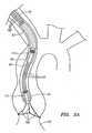
- FIG. 1shows an exemplary embodiment of a heart valve assembly 10 that generally includes a base member or "gasket member” 12 and a valve member or “crown" 14.
- filaments, sutures, or other elongate guide elements 96may also be provided, e.g., in a system or kit, to guide the gasket member 12 and/or valve member 14 into an implantation site (not shown) and/or to secure the valve member 14 to the gasket member 12, as described further below.
- the valve member 14may include an annular shaped body or frame 32 and one or more valve elements 33.
- the valve member 14is a bioprosthetic valve, i.e., an annular frame 32 carrying a plurality of tissue leaflets 33 extending from the frame 32, e.g., attached to commissures 34.
- the frame 32may have a noncircular, e.g., multiple lobular shape, such as a tri-lobular shape, including three lobes separated by cusps or scallops.
- the frame 32 and/or other components of the valve member 14may include a fabric covering (not shown), e.g., to enhance sealing and/or facilitate tissue ingrowth, which may be sutured or otherwise secured around, over, or otherwise to the component(s).
- the valve member 14may include a plurality of struts (not shown) that may be attached to the frame 32 and/or otherwise carry the leaflets or other valve elements 33.
- the strutsmay include a laminate structure, including two or more sheets of flexible material, similar to the struts disclosed in U.S. Patent No. 6,371,983 ("the '983 Patent").
- the leafletsmay be formed from tissue, such as bovine pericardium, as described in the '983 Patent. Exemplary leaflets and methods for assembling them into crowns are described in co-pending application Serial No. 11/144,254, filed June 3, 2005 .
- valve member 14may be a connecting device to which a valve (not shown) may be connected or that may otherwise receive a valve component, such as the connection adapter elements shown in co-pending application Serial No. 10/646,639, filed August 22, 2003 .
- valve member 14may include a mechanical valve or other valve (not shown), such as those disclosed in application Serial Nos. 10/765,725, filed January 26, 2004 , 11/069,457, filed February 28, 2005 , and 60/669,704, filed April 8, 2005 .
- the valve member 14may be contractible into a contracted condition to facilitate introduction into a catheter or other delivery device (not shown), e.g., to allow delivery endoluminally through a patient's vasculature, as explained further below.
- the valve member 14may have an enlarged or relaxed condition, which may correspond to the desired configuration for the valve member 14 once it is implanted and in use within a biological annulus, e.g., above a native aortic, mitral, pulmonary valve site within a patient's heart.
- the frame 32may be folded out of plane (e.g., as represented by arrow A in FIG.
- valve member 14may be loaded into a catheter or other delivery device (not shown), as explained further below.
- the gasket member 12generally includes an annular ring 18, and a sewing cuff 20 extending radially outwardly from the annular ring 18.
- the gasket member 12may also include a collar or stand-off 22, such as those disclosed in application Serial No. 60/685,265, filed May 27, 2005 .
- a fabric coveringmay be provided on one or more components of the gasket member 12, e.g., to enhance sealing and/or facilitate tissue ingrowth.
- the annular ring 18may have a generally circular shape, although alternatively, the annular ring 18 may have a multi-lobular shape about the circumference, e.g., including three lobes separated by scallops or cusps (not shown).
- the annular ring 18may be formed from an elastic or superelastic material, such as Nitinol, Elgiloy, stainless steel, and the like.
- the annular ring 18may be cut from a flat sheet of base material having a desired thickness for the annular ring 18, for example, by laser cutting, mechanical cutting, and the like.
- the annular ring 18may be initially formed as a long band of material, having a width corresponding to the desired width of the annular ring 18.
- the bandmay be wrapped around a mandrel or otherwise restrained in a generally cylindrical shape with the ends adjacent to one another, and the band may be heat treated or otherwise processed to program the generally cylindrical shape to create the annular ring 218.
- the generally cylindrical shapemay include the ends overlapping one another, spaced apart from one another to provide an open "C" shape, or attached to one another.
- the fabricmay be wrapped around the annular ring 18, while accommodating expansion and contraction of the annular ring 18.
- the fabricmay not be secured to the annular ring 18, allowing the ends to slide circumferentially relative to the fabric.
- sutures and the likemay be used to secure the fabric to the annular ring 18 at locations removed from the ends, e.g., at one or more intermediate locations about the circumference of the annular ring 18.
- the entire annular ring 18may be free to slide within the fabric wrapped around the annular ring 18.
- the sewing cuff 20may be attached to or otherwise extend around the annular ring 18.
- the sewing cuff 20may simply be a layer of fabric or other material covering at least a portion of the annular ring 18.
- the sewing cuff 20may include flexible core material (not shown) that may be attached to or otherwise extend around the annular ring 18, e.g., from an upper edge of the annular ring 18.
- the gasket member 12includes the collar 20, the collar 22 may be attached to or otherwise extend upwardly from the annular ring 18 and/or the sewing cuff 20.
- the collar 22 and sewing cuff 20may include a core that is formed as a unitary piece or attached together.
- the material of the coremay be substantially flexible, e.g., manufactured in a desired annular shape, yet easily deformed, e.g., deflected, stretched, and/or compressed.
- Exemplary materials for the coreinclude silicone or other elastomeric materials, foam, fabric, felt, polymers, and the like.
- the materialsmay be molded or otherwise formed into the core, e.g., using known molding, extrusion, cutting, or other manufacturing procedures.
- the gasket member 12may include one or more attachment zones 26 (one shown in phantom).
- the attachment zone(s) 26may include a connector for securing the valve member 14 relative to the gasket member 12 and/or may define an area of where the valve member 14 contacts the gasket member 12 when the valve member 14 is secured relative to the gasket member 12, e.g., to provide a desired seal.
- the gasket member 12may be contractible into a contracted condition to facilitate delivery.
- the gasket member 12may be biased to expand to a predetermined diameter, e.g., to an enlarged condition corresponding to the biological annulus within which the gasket member 12 is to be implanted.
- the gasket member 12may be compressed, e.g., by flattening the annular ring 18, and then rolling the ends, similar to the crown 14, as described above.
- the gasket member 12may then be loaded into a catheter 60 or other delivery device (not shown), e.g., adjacent the crown 14.
- the gasket member 12may be compressed into a contracted condition resembling a clover, e.g., by directing multiple portions of the annular ring 18 radially inwardly relative to adjacent portion, thereby defining a plurality of petals.
- This configurationmay be sufficiently small to allow the gasket member 12 to be loaded into a delivery device.
- the petalsmay be folded together to further compress the gasket member 12. Exemplary contracted configurations are shown in US application Serial No. 60/746,038, filed April 29, 2006 .
- the frame 32 of the valve member 14may be compressed in a similar manner, taking care not to damage the leaflets 33.
- the frame 32 and/or other component of the valve member 14may include one or more connectors for securing the valve member 14 relative to the gasket member 12.
- the gasket member 12may include one or more mating connectors and/or receivers for cooperating with the connectors on the valve member 14.
- the valve member 14 and/or gasket member 12may include one or more receivers for receiving a suture or other filament therethrough, e.g., to guide and/or secure the valve member 14 and/or gasket member 12, as described further below.
- valve member 14 and/or gasket member 12may include one or more radiopaque markers or other guiding elements, e.g., that may be visualized using fluoroscopy or other external imaging to facilitate positioning and/or implantation of the valve member 14 and/or gasket member 12.
- the heart valve assembly 10may include a gasket member 12 and a valve member 14 loaded into a catheter 60, thereby providing a system that may be used to deliver and/or implant the heart valve assembly 10 into a biological annulus 92,e.g., to replace a native aortic valve 94.
- the gasket member 12 and valve member 14are disposed adjacent one another within a lumen 62 of the catheter 60 adjacent to a distal end 64, which may be tapered or otherwise sized and/or shaped to facilitate introduction into a patient's vasculature or other body lumens.
- the gasket member 12is disposed immediately adjacent the distal end 64 and the valve member 14 is disposed proximal to the gasket member 12 such that the gasket member 12 and valve member 14 may be delivered successively from the catheter 60.
- the catheter 60may include one or more pusher members (not shown) adjacent to the gasket member 12 and/or valve member 14, which may be used to deploy the gasket member 12 and/or valve member 14.
- the pusher member(s)may include one or more tubular bodies or other structures (not shown) that restrain the gasket member 12 and/or valve member 14 from axial movement when the catheter 60 is retracted, thereby exposing the gasket member 12 and crown 14 beyond the distal end 64.
- a first pusher membermay be provided that includes a distal end disposed adjacent the gasket member 12, and a second pusher member may be provided that includes a distal end disposed adjacent the valve member 14.
- the first pusher membermay include a lumen, slot, or other feature for accommodating the valve member 14 and/or second pusher member.
- the componentsmay be loaded into the catheter 60, e.g., during manufacturing or any time before delivery into a patient.
- the gasket member 12 and valve member 14may be contracted or folded separately from each other and loaded successively into the catheter 60, e.g., from the distal end 64. If the catheter 60 includes a pusher member for carrying the components, the gasket member 12 and valve member 14 may be loaded onto the pusher member, which may then be inserted into the catheter 60.
- One of the advantages of separating the gasket member 12 and valve member 14 and loading them separatelyis that they may be folded or otherwise compressed to a smaller diameter or size than if folded after the gasket member 12 and valve member 14 are attached to each other. Furthermore, folding the gasket member 12 and valve member 14 separately may reduce stress on the gasket member 12 and valve member 14 while contracted, which may improve durability of the heart valve assembly 10.
- Guide elementsare loaded into the catheter 60 during manufacturing and/or assembly.
- the guide elementsmay be directed through the features before loading the gasket member 12 and/or valve member 14 into the catheter 60.
- the guide elementsare directed through the catheter 60, e.g., to the proximal end (not shown), e.g., such that the guide elements extend from the proximal end, through the valve member 14 and/or gasket member 12 (e.g., through lumen 62) and to the distal end 64 of the catheter 60.
- the guide elementsextend a predetermined distance out of the distal end 64 of the catheter 60, e.g., to provide sufficient length that may introduced into a patient before the catheter 60.
- the guide elements 96are delivered and attached to tissue surrounding the biological annulus 92.
- the sutures 96may be delivered from a percutaneous entry site, e.g., a puncture in the femoral, carotid, radial, or other artery, into the aortic root. From within the aortic root, the sutures may be driven through or otherwise secured to the tissue surrounding the biological annulus 92. If desired, knots may be directed down the sutures 96 to the location where they are secured to the tissue surrounding the biological annulus 92. Alternatively, the sutures 96 may include two ends that extend from the biological annulus 92. Thus, the sutures 96 may extend from the biological annulus 92, through any intervening vasculature to the percutaneous entry site, and out of the patient's body.
- a percutaneous entry sitee.g., a puncture in the femoral, carotid, radial, or other artery
- the suturesmay be driven through or otherwise secured to the tissue surrounding the biological annulus 92. If desired, knots may be directed down the sutures
- the catheter 60may be introduced through the percutaneous entry site, and advanced through the patient's vasculature over the sutures 96 into the aortic root. For example, free ends of the sutures 96 may be backloaded into the distal end 64 of the catheter 60, through the gasket member 12 and/or valve member 14, and the catheter 60 to the proximal end. Alternatively, as described above, the sutures 96 may be preloaded through the catheter 60.
- the catheter 60may be inserted through an introducer sheath or other device (not shown) at the entry site, using known procedures.
- the gasket member 12may be deployed from the distal end 64, e.g., by retracting the catheter 60 partially and using a pusher member or otherwise preventing proximal movement of the gasket member 12.
- the gasket member 12may resiliently return to its expanded or relaxed condition.
- the gasket member 12may be expanded or "unfurled” as it is advanced distally along the sutures 96.
- a tool(not shown) may be advanced over the sutures 96 or over the catheter 60, which may be used to expand the gasket member 12.
- the gasket member 12may then be seated within the biological annulus 92.
- the pusher member(not shown) may be advanced to direct the gasket member 12 over the sutures 96, e.g., into the site of the native valve leaflets 94. If the native valve leaflets 94 remain within the biological annulus 92 during delivery, the gasket member 12 may deflect the leaflets 94 outwardly to open the biological annulus 92.
- the gasket member 12may at least partially dilate the biological annulus 92, similar to the methods in the applications identified above, e.g., because of the resilient bias of the annular ring 18 to expand radially outwardly.
- the gasket member 12may be advanced into the biological annulus 92 using a delivery tool (not shown). The gasket member 12 may be advanced until the annular ring 18 extends at least partially into the biological annulus 92. In one embodiment, the annular ring 18 and/or other component of the gasket member 12 may extend entirely through the biological annulus, with the lower edge of the annular ring 18 remaining free within the sub-annular space below the biological annulus 92.
- the gasket member 12may include a flexible skirt (not shown) that may extend below through the biological annulus 92 when the gasket member 12 is secured. The skirt may be biased to extend outwardly, e.g., to provide a smooth transition and/or enhance a seal between the heart vale assembly 10 and the biological annulus 92.
- the sewing cuff 20may contact the tissue within the supra-annular space above the biological annulus 92, although the sewing cuff 20 may not provide any structural support of the annular ring 18.
- the annular ring 18may then be expanded within the biological annulus, e.g., to dilate the biological annulus or otherwise direct the surrounding tissue outwardly against the underlying tissue structures.
- a dilation tool(not shown) may be advanced into the gasket member 12 and expanded to forcibly (e.g., plastically) expand the annular ring 18 within the biological annulus 92.
- the sewing cuff 20may be released to allow the sewing cuff 20 to contact the surrounding tissue, e.g., within the aortic root above the biological annulus 92.
- the sewing cuff 20may adopt the shape of the surrounding tissue, e.g., lying flatter within the coronary sinus regions, while becoming more vertical adjacent the commissures.
- the gasket member 12may be secured within the biological annulus 92 simply by the frictional engagement between the annular ring 18 and the surrounding tissue.
- the annular ring 18 and/or sewing cuff 20may include one or engagement elements (not shown) that puncture or otherwise engage the surrounding tissue to enhance securing the gasket member 12.
- a plurality of fastenerse.g., clips, staples, sutures, and the like, may be directed through the sewing cuff 20 into the tissue surrounding the biological annulus 92 to secure the gasket member 12 relative to the biological annulus 92.
- valve member 14may then be deployed from the catheter 60 (or from a separate delivery device after delivering fasteners through the gasket member 12) and advanced into the biological annulus 92.
- the valve member 14may be advanced over the sutures 96 until connectors on the gasket member 12 and/or valve member 14 engage to secure the valve member 14 to the gasket member 12.
- the valve member 14 and/or gasket member 12may include one or more cooperating clips, detents, and the like that may self-engage when the valve member 14 is docked against the sewing cuff 20 or otherwise into the gasket member 12, similar to the embodiments described in the applications identified above.
- valve member 14may be secured to the collar 22, e.g., using one or more connectors on the valve member 14 and/or collar 22, e.g., a drawstring (not shown).
- sutures 96may be used to secure the valve member 14 to the gasket member 12, similar to the embodiment shown in FIGS. 3A and 3B and described further elsewhere herein.
- FIGS. 3A-3Canother embodiment of a heart valve assembly 110 is shown that includes a gasket member 112 and a valve member or crown 114, which may be constructed similar to the other embodiments described herein.
- the gasket member 112includes an annular ring 118, and a sewing cuff 120, which may be similar to the previous embodiments.
- the gasket member 112includes a plurality of posts 124 extending upwardly, e.g., from the annular ring 118.
- the posts 124may include passages, tubular elements, or other receivers (not shown) for receiving sutures or other filaments 196 therethrough.
- the sutures 196may be attached to ends or other portions of the posts 124.
- the sutures 196may include detents or other connectors 197 disposed a predetermined distance from the ends of the posts 124.
- the connectors 197may be formed from plastic or metal components fixed to the sutures 196 and including ramped or tapered proximal surfaces and blunt distal surfaces or edges.
- the connectors 197are conical features.
- the connectors 197'may be ratcheting features, e.g., including harpoon tips and/or one or more, e.g., a plurality of one-way ratchets.
- the valve member 114includes a sleeve 132, e.g., of bovine pericardium or other tissue, synthetic material, fabric, and the like, which may be formed to provide a plurality of leaflets 133.
- the sleeve 132may also include a plurality of tubes or other receivers 134, which may be formed the same material as the leaflets 133, e.g., bovine pericardium, and/or other material, e.g., fabric.
- the tubes 134may be formed by bonding, stitching, and/or otherwise attaching portions of the sleeve 132 to create the tubes 134 between adjacent leaflets 133.
- the tubes 134may be formed from separate material attached to the sleeve 132, e.g., cloth, silicone, and/or other material that may be flexible, for example, so that the tubes 134 may be folded and/or expanded easily.
- the tubes 134may be sized to be received over the posts 124 of the gasket member 112, as explained further below.
- the valve member 114may include a cloth ring 136 at the base of the tubes 134, e.g., for providing a tissue ingrowth surface.
- the cloth ring 136may be formed from cloth and, optionally, may include a silicone or other core (not shown), which may be attached to the sleeve 132, e.g., by stitching, bonding, and the like.
- the cloth ring 136may provide an additional interface with the gasket member 112, e.g., to enhance sealing when the valve member 114 is secured relative to the gasket member 112.
- the gasket member 112 and valve member 114may be loaded into a catheter 60, similar to the previous embodiments.
- the catheter 60may include a pusher member 63 adjacent to the gasket member 112 and/or valve member 114, which may be used to deploy the gasket member 112 and/or valve member 114, similar to embodiments described elsewhere herein.
- a pusher wire 73may be attached to the pusher member 63, which may extend proximally through the catheter 60.
- the pusher wire 73may be coupled to an actuator, e.g., a slider, button, dial, or other feature (not shown), on a handle (also not shown) on the proximal end of the catheter 60.
- an actuatore.g., a slider, button, dial, or other feature (not shown) on a handle (also not shown) on the proximal end of the catheter 60.
- the actuator and pusher wire 73may be used to hold or push the pusher member 63 relative to the catheter 60, e.g., along the catheter lumen 62.
- the catheter 60may be advanced over sutures 196 previously attached to tissue surrounding the biological annulus 92, e.g., as described above.
- the gasket member 112may be deployed from the catheter 60 and advanced over the sutures 196 into the biological annulus 92, similar to the methods described above. If the sutures 196 include the connectors 197, such as those shown in FIGS. 3A-3C (and not shown in FIGS.
- the gasket member 112may be advanced such that the connectors 197 pass through passages or receivers in the gasket member 112.
- the proximal end of the passages in the gasket member 112may include a narrow region, one or more tabs, and the like (not shown) that may allow the connectors 197 to pass through as the gasket member 112 is advanced, but prevent the gasket member 112 from being withdrawn back over the connectors 197.
- the sutures 196 and connectors 197may simply pass through a portion of the fabric covering on the gasket member 112, e.g., covering the sewing cuff 120.
- the valve member 114may be deployed from the catheter 60, e.g., similar to the previous methods, and advanced over the sutures 196 until the valve member 114 is docked to the gasket member 112.
- the connectors 197may pass through the tubes 134 of the valve member 14 until the connectors 197 exit from the proximal or upper ends of the tubes 134. This advancement may be facilitated by the ramped proximal surfaces of the connectors 197.
- valve member 114may be substantially secured relative to the gasket member 112, e.g., against the gasket member 112, as shown in FIG. 3C .
- the sutures 196may include weakened or break-away areas, e.g., immediately above the connectors 197 that may separate when a threshold tensile force is applied to the sutures 196.
- a cutter or other toolmay be advanced into the aortic root (or other region adjacent the biological annulus 92) and manipulated to cut or otherwise sever the sutures 196 above the connectors 197.
- the crown 114may simply be a sleeve 132 formed from tissue, and may not include a frame, unlike the previous embodiments. This may facilitate rolling or otherwise contracting the crown 114 into a delivery condition.
- the embodimentmay eliminate any risk of metal or other frame components damaging tissue leaflets during contraction and/or expansion.
- the posts 124 on the gasket member 112provide a frame-like support structure that supports the sleeve 132 and allows the leaflets of the sleeve 132 to open and close during beating of the heart.
- posts 124' on a gasket member 112'may include detents, tabs, or other connectors 128' that may accommodate receiving a portion of a valve member 114,' e.g., tubes 134' over the posts 124.
- the tubes 134'may include receptacles 138' that interlock or otherwise engage with the connectors 128' to secure the valve member 114' to the gasket member 112.
- the tabs 128'may present a tapered edge that allows the tubes 134' to pass freely over the posts 124,' yet is biased to resiliently return outwardly to prevent removal or other movement of the tubes 134' off of the posts 124.
- the receptacles 138'receive the outwardly returned tabs 128'.
- a valve member or crown 214that includes an expandable frame 232 that may be compressed inwardly into a delivery condition (shown in FIG. 7A ) and expandable to a deployed condition (shown in FIG. 7B ).
- the valve member 214may include an annular shaped body or frame 232, one or more valve elements 233, and a base 232a.
- the valve member 214is a bioprosthetic valve member, i.e., an annular frame 232 carrying a plurality of tissue leaflets 233 extending from the frame 232, e.g., attached to commissures 234.
- the frame 232may have a noncircular, e.g., multiple lobular shape, such as a tri-lobular shape, including three lobes separated by cusps or scallops.
- the frame 232may include one or more connectors (not shown) for mating with a cooperating connector on a gasket member (also not shown), similar to other embodiments described elsewhere herein.
- the frame 232 and/or other components of the valve member 214may include a fabric covering 235, e.g., to enhance sealing and/or facilitate tissue ingrowth, which may be sutured or otherwise secured around, over, or otherwise to the component(s).
- the fabric covering 235comprises a polyester material, e.g., Dacron.
- the frame 232may be formed from one or more rod elements, e.g., that have portions removed to provide a desired flexibility for the frame 232.
- An exampleuses a solid Nitinol bar that is machined using methods known in the art to create the frame 232, e.g., conventional machining, electrical discharge machining (EDM), laser, and water jet machining.
- the frame 232may include a stent member 236 attached to the base 232a of the valve member 214 for increasing expandability of the valve member 214 within a gasket member.
- the stent member 236may comprise materials similar to those described above for making annular rings, e.g., Nitinol or other elastic or superelastic material.
- the valve member 214may include a plurality of struts (not shown) that may be attached to the frame 232 and/or otherwise carry leaflets or other valve elements 233.
- the strutsmay include a laminate structure, similar to previous embodiments.
- the leaflets 233may be formed from tissue, such as bovine pericardium, also similar to previous embodiments.
- the valve member 214may be a connecting device to which a valve 233 may be connected or that may otherwise receive a valve component, as described elsewhere herein.
- the valve member 214may include a mechanical valve or other valve (not shown), also as described elsewhere herein.
- the valve member 214may be compressible into the delivery condition using a valve holder tool 270, shown in FIG. 7A , e.g., to facilitate introduction into a delivery catheter (not shown) and/or deployment from the delivery catheter.
- the frame 232may be folded inwardly using the tool 270, bringing each of the commissures 234 inwardly towards one another.
- the tool 270may include a central core member (not shown) including a plurality of lobes, and a plurality of movable arms disposed between adjacent lobes (also not shown).
- the frame 232may be disposed between the core member and the arms, and the arms may be directed inwardly to fold the frame 232, e.g., similar to tools disclosed in US application Serial No. 60/746,038 .
- the tool 270 and valve member 214may be loaded into a delivery catheter (not shown).
- the tool 270may have an elongate flexible or semi-rigid body (not shown), which may extend through the delivery catheter, yet allow the delivery catheter to be advanced through a patient's vasculature.
- the valve member 214 and tool headmay be advanced from the delivery catheter, and the frame 232 may be expanded, e.g., by releasing the arms or other actuator on the tool.
- the frame 232may resiliently expand, e.g., the commissures 234 may automatically separate from one another to open the leaflets 233.
- the valve member 214may then be secured relative to a gasket member (not shown), similar to the other embodiments described elsewhere herein.
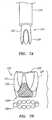
- FIG. 8A and 8Bshown are details of a commissure 234 that may be provided on the frame 232 of the valve member 214 shown in FIGS. 7A and 7B .
- the frame 232(or struts, not shown, attached to the frame 232) may include a plurality of holes or other commissure attachment points 237. Sutures or other connectors (not shown) may be directed through the holes 237 to attach a leaflet (also not shown) to the commissure 234, similar to the previous embodiments.
- the thickness of the commissure 234may be varied to provide a desired stiffness.
- the tip of the commissure 234may be thinner than base portions of the frame 232, e.g., to allow greater flexibility of the tip of the commissure 234 for upper edges of leaflets (not shown) attached to the frame 232.
- the plurality of commissure attachment points 237provide alternative locations for attaching tissue leaflets (not shown) to the frame 232.
- FIGS. 9A and 9Bshow an example of a frame 232.
- the frame 232'includes pairs of commissures 234' (one shown) spaced apart around the circumference of the frame 232,' each commissure including a plurality of holes or other commissure attachment points 237.' Each pair of commissures 234' may support edges of individual, adjacent leaflets (not shown) such that each leaflet is independently supported.
- the commissures 234'may be directed inwardly towards one another (as shown in FIG. 9A ) as the frame 232' is contracted to the delivery condition and may resiliently move away from one another (as shown in FIG. 9B ) when the frame 232' is released, e.g., during deployment and implantation of the heart valve assembly, similar to the previous embodiments.
- FIGS. 10A-11Bshow alternative constructions and methods for attaching leaflets to an expandable frame, e.g., to provide a valve member (not shown), such as those described elsewhere herein.
- FIGS. 10A and 10Bshow a portion of a frame 332 that includes a commissure 334 to which a leaflet 333 is attached. As best seen in FIG. 10B , the edges of the leaflets 333 may be received within a channel 334d formed in the commissure 334, e.g., defined by two sides 334a, 334b and a backside 334c. The edges 333a of the leaflets 333 may abut into the channel 334d.
- One or more sutures 396(as seen in FIG.
- the commissure 334may include one or more holes, slots, and the like (not shown), similar to those shown in FIGS. 8A-9B , for receiving the sutures 396 therethrough.
- a frame 332'may include a plurality of commissures 334' spaced apart around a circumference of the frame 332.
- Each commissure 334'may include two sides 334a', 334b' and a backside 334c.
- the two sides 334a', 334b'may extend upwardly beyond the backside 334c,' thereby defining posts around which edges 333a' of valve leaflets 333' may be wrapped.
- Sutures 396'may then be applied along the suture line 305' to secure the leaflets 333' to the frame 332,' similar to the previous embodiments.
Landscapes
- Health & Medical Sciences (AREA)
- Cardiology (AREA)
- Engineering & Computer Science (AREA)
- Biomedical Technology (AREA)
- Heart & Thoracic Surgery (AREA)
- Transplantation (AREA)
- Oral & Maxillofacial Surgery (AREA)
- Vascular Medicine (AREA)
- Life Sciences & Earth Sciences (AREA)
- Animal Behavior & Ethology (AREA)
- General Health & Medical Sciences (AREA)
- Public Health (AREA)
- Veterinary Medicine (AREA)
- Prostheses (AREA)
Description
- Prosthetic heart valves can replace defective human valves in patients. For example, one piece valves have been suggested that include sewing rings or suture cuffs that are attached to and extend around the outer circumference of a prosthetic valve. In addition, multiple component valves have also been suggested that include a sewing ring that is separate from a valve component. The sewing rings of either type of prosthetic valve can be tedious and time consuming to secure within a target site, i.e., within an annulus of a heart where a natural heart valve has been removed.
- For example, to implant a sewing ring within an annulus of a heart, between twelve and twenty sutures may be secured initially to tissue surrounding the annulus. The sewing ring and/or the entire prosthetic valve may then be advanced or "parachuted" down the sutures into the annulus. Knots may then be tied with the sutures to secure the sewing ring within the annulus, whereupon the sutures may be cut and the excess removed. Consequently, this procedure can be very complicated, requiring management and manipulation of many sutures. The complexity of the procedure also provides a greater opportunity for mistakes and requires a patient to be on cardiopulmonary bypass for a lengthy period of time.
- Because the annulus of the heart may not match the circular cross-section of the sewing ring and/or prosthetic valve, the prosthetic valve may not fit optimally within the annulus. As a result, natural blood hemodynamics through and around the valve may be impaired, resulting in clotting, possible emboli production, and eventual calcification of the valve structure.
- To address this concern, flexible sewing rings have been suggested for use with multiple component valves. The sewing ring may be implanted within the annulus, e.g., using the procedure described above, i.e., parachuted down an arrangement of sutures. The sewing ring may conform at least partially to the anatomy of the annulus. Alternatively, instead of using sutures, it has also been suggested to drive staples through the sewing ring into the surrounding tissue to secure the sewing ring.
- When a mechanical or prosthetic valve is then attached to the sewing ring, however, the valve and sewing ring may not mate together effectively, e.g., if the shape of the sewing ring has been distorted to conform to the annulus, which may also impair natural blood hemodynamics, create leaks, and/or otherwise impair performance of the prosthetic valve.
- Percutaneous valves have also been suggested that may be delivered using a catheter or other device, e.g., from a percutaneous delivery site. Such valves, however, risk damage to tissue leaflets and/or other components of the valves, e.g., due to the substantial compression and expansion involved during delivery. In addition, such valves may be difficult to attach to a native biological annulus.
US 2005/0043760 describes a biologically implantable prosthesis with engagement elements for engagement between a first and a second element of the prosthesis.- The present invention is directed to heart valves that may be implanted within a patient, and, more particularly, to multiple component heart valve assemblies that may be delivered endoluminally into a patient's heart, e.g., from a percutaneous entry site.
- In accordance with an embodiment, a system is provided for delivering a multiple component prosthetic valve into a biological annulus within a patient's body that includes an elongate tubular member including a proximal end, a distal end sized for introduction into a body lumen, and a lumen extending between the proximal and distal ends. A first annular prosthesis may be disposed within the tubular member adjacent the distal end in a contracted condition, the annular prosthesis being expandable upon deployment from the tubular member within the biological annulus. A second valve prosthesis may be disposed within the tubular member adjacent the annular prosthesis in a contracted condition, the valve prosthesis being expandable upon deployment from the tubular member within the biological annulus such that the valve prosthesis may be secured to the annular prosthesis.
- The system includes a plurality of elongate guide elements including a first end attachable to tissue surrounding a biological annulus and having sufficient length to extend from the biological annulus to a percutaneous entry site. The guide elements may be sized to be received through at least one of the tubular member, the annular prosthesis, and the valve prosthesis. For example, the valve prosthesis may include a plurality of passages for receiving respective guide elements therethrough such that the valve prosthesis may be advanced over the guide elements. In addition or alternatively, the annular prosthesis may include a plurality of passages for receiving respective guide elements therethrough such that the annular prosthesis may be advanced over the guide elements. Alternatively, the guide elements may be secured to the annular prosthesis. Optionally, each of the guide elements may include one or more connectors spaced apart from the first end for securing at least one of the annular prosthesis and the valve prosthesis relative to tissue to which the first end is attached.
- In one embodiment, the system may include one or more pusher members disposed within the tubular member, the pusher member(s) adjacent at least one of the annular and valve prostheses, and being movable relative to the tubular member for deploying at least one of the annular and valve prostheses.
- Other aspects and features of the present invention will become apparent from consideration of the following description taken in conjunction with the accompanying drawings.
Figures 1 to 6 illustrate exemplary embodiments of the invention, in which:FIG. 1 is a perspective view of a two piece heart valve assembly including a gasket member and a valve member that has been partially folded.FIGS. 1A and 1B are details showing a method for folding the valve member ofFIG. 1 into a compressed delivery condition.FIG. 2 is a cross-sectional view of a patient, showing a method for delivering the heart valve assembly ofFIG. 1 .FIGS 3A-3C are perspective views of another two piece heart valve assembly including a gasket member and a valve member, showing the valve member being directed towards the gasket member over guide elements and secured to the gasket member using connectors on the guide elements and receiving tubes of the valve member over posts of the gasket member.FIG. 4 is a detail showing an alternative structure for securing the valve member to the gasket member, including a plurality of ratcheting elements on a guide member.FIGS. 5-5C are cross-sectional views of a patient, showing a method for implanting a heart valve assembly into a biological annulus.FIG. 6 is a detail showing another alternative structure for securing a valve member to a gasket member, including cooperating connectors on the valve member and gasket member.FIGS. 7A and 7B are perspective views of a heart valve member in compressed and expanded conditions, respectively.FIGS. 8A and 8B are details of posts that may be provided on the heart valve member ofFIGS. 7A and 7B .FIGS. 9A and 9B are details of alternative posts that may be provided on a heart valve member, such as that shown inFIGS. 7A and 7B .FIGS. 10A and 10B are front and top views, respectively, of a commissure of a heart valve member with leaflets attached thereto.FIGS. 11A and 11B are front and top views, respectively, of a commissure of a heart valve member with leaflets attached thereto.- Turning to the drawings,
FIG. 1 shows an exemplary embodiment of aheart valve assembly 10 that generally includes a base member or "gasket member" 12 and a valve member or "crown" 14. In addition, as shown inFIG. 2 , filaments, sutures, or otherelongate guide elements 96 may also be provided, e.g., in a system or kit, to guide thegasket member 12 and/orvalve member 14 into an implantation site (not shown) and/or to secure thevalve member 14 to thegasket member 12, as described further below. - As shown in
FIG. 1 , thevalve member 14 may include an annular shaped body orframe 32 and one ormore valve elements 33. In an exemplary embodiment, thevalve member 14 is a bioprosthetic valve, i.e., anannular frame 32 carrying a plurality oftissue leaflets 33 extending from theframe 32, e.g., attached tocommissures 34. Theframe 32 may have a noncircular, e.g., multiple lobular shape, such as a tri-lobular shape, including three lobes separated by cusps or scallops. Theframe 32 and/or other components of thevalve member 14 may include a fabric covering (not shown), e.g., to enhance sealing and/or facilitate tissue ingrowth, which may be sutured or otherwise secured around, over, or otherwise to the component(s). - The
valve member 14 may include a plurality of struts (not shown) that may be attached to theframe 32 and/or otherwise carry the leaflets orother valve elements 33. For example, the struts may include a laminate structure, including two or more sheets of flexible material, similar to the struts disclosed inU.S. Patent No. 6,371,983 ("the '983 Patent"). The leaflets may be formed from tissue, such as bovine pericardium, as described in the '983 Patent. Exemplary leaflets and methods for assembling them into crowns are described in co-pending application Serial No.11/144,254, filed June 3, 2005 - Alternatively, the
valve member 14 may be a connecting device to which a valve (not shown) may be connected or that may otherwise receive a valve component, such as the connection adapter elements shown in co-pending application Serial No.10/646,639, filed August 22, 2003 valve member 14 may include a mechanical valve or other valve (not shown), such as those disclosed in application Serial Nos.10/765,725, filed January 26, 2004 11/069,457, filed February 28, 2005 60/669,704, filed April 8, 2005 - Turning to
FIGS. 1A and 1B , thevalve member 14 may be contractible into a contracted condition to facilitate introduction into a catheter or other delivery device (not shown), e.g., to allow delivery endoluminally through a patient's vasculature, as explained further below. For example, as shown inFIG. 1A , thevalve member 14 may have an enlarged or relaxed condition, which may correspond to the desired configuration for thevalve member 14 once it is implanted and in use within a biological annulus, e.g., above a native aortic, mitral, pulmonary valve site within a patient's heart. As shown inFIG. 1 , theframe 32 may be folded out of plane (e.g., as represented by arrow A inFIG. 1A ), thereby generally defining two generally semi-circular portions adjacent one another. The opposite ends of theframe 32 may then be rolled towards one another (e.g., as represented by arrows B inFIG. 1A ), until thevalve member 14 is folded or rolled into the contracted condition shown inFIG. 1B . In the contracted condition, thevalve member 14 may be loaded into a catheter or other delivery device (not shown), as explained further below. - Returning to
FIG. 1 , thegasket member 12 generally includes anannular ring 18, and asewing cuff 20 extending radially outwardly from theannular ring 18. Optionally, thegasket member 12 may also include a collar or stand-off 22, such as those disclosed in application Serial No.60/685,265, filed May 27, 2005 gasket member 12, e.g., to enhance sealing and/or facilitate tissue ingrowth. In one embodiment, theannular ring 18 may have a generally circular shape, although alternatively, theannular ring 18 may have a multi-lobular shape about the circumference, e.g., including three lobes separated by scallops or cusps (not shown). - The
annular ring 18 may be formed from an elastic or superelastic material, such as Nitinol, Elgiloy, stainless steel, and the like. For example, theannular ring 18 may be cut from a flat sheet of base material having a desired thickness for theannular ring 18, for example, by laser cutting, mechanical cutting, and the like. Thus, theannular ring 18 may be initially formed as a long band of material, having a width corresponding to the desired width of theannular ring 18. The band may be wrapped around a mandrel or otherwise restrained in a generally cylindrical shape with the ends adjacent to one another, and the band may be heat treated or otherwise processed to program the generally cylindrical shape to create the annular ring 218. The generally cylindrical shape may include the ends overlapping one another, spaced apart from one another to provide an open "C" shape, or attached to one another. - When the
annular ring 18 is at least partially covered with fabric, the fabric may be wrapped around theannular ring 18, while accommodating expansion and contraction of theannular ring 18. For example, at least near the ends, the fabric may not be secured to theannular ring 18, allowing the ends to slide circumferentially relative to the fabric. Optionally, sutures and the like (not shown) may be used to secure the fabric to theannular ring 18 at locations removed from the ends, e.g., at one or more intermediate locations about the circumference of theannular ring 18. Alternatively, the entireannular ring 18 may be free to slide within the fabric wrapped around theannular ring 18. - The
sewing cuff 20 may be attached to or otherwise extend around theannular ring 18. Thesewing cuff 20 may simply be a layer of fabric or other material covering at least a portion of theannular ring 18. Alternatively, thesewing cuff 20 may include flexible core material (not shown) that may be attached to or otherwise extend around theannular ring 18, e.g., from an upper edge of theannular ring 18. If thegasket member 12 includes thecollar 20, thecollar 22 may be attached to or otherwise extend upwardly from theannular ring 18 and/or thesewing cuff 20. Optionally, thecollar 22 andsewing cuff 20 may include a core that is formed as a unitary piece or attached together. The material of the core may be substantially flexible, e.g., manufactured in a desired annular shape, yet easily deformed, e.g., deflected, stretched, and/or compressed. Exemplary materials for the core include silicone or other elastomeric materials, foam, fabric, felt, polymers, and the like. The materials may be molded or otherwise formed into the core, e.g., using known molding, extrusion, cutting, or other manufacturing procedures. - Optionally, the
gasket member 12 may include one or more attachment zones 26 (one shown in phantom). The attachment zone(s) 26 may include a connector for securing thevalve member 14 relative to thegasket member 12 and/or may define an area of where thevalve member 14 contacts thegasket member 12 when thevalve member 14 is secured relative to thegasket member 12, e.g., to provide a desired seal. - As shown in
FIGS. 1 and2 , thegasket member 12 may be contractible into a contracted condition to facilitate delivery. In one embodiment, thegasket member 12 may be biased to expand to a predetermined diameter, e.g., to an enlarged condition corresponding to the biological annulus within which thegasket member 12 is to be implanted. Thegasket member 12 may be compressed, e.g., by flattening theannular ring 18, and then rolling the ends, similar to thecrown 14, as described above. Thegasket member 12 may then be loaded into acatheter 60 or other delivery device (not shown), e.g., adjacent thecrown 14. - Alternatively, the
gasket member 12 may be compressed into a contracted condition resembling a clover, e.g., by directing multiple portions of theannular ring 18 radially inwardly relative to adjacent portion, thereby defining a plurality of petals. This configuration may be sufficiently small to allow thegasket member 12 to be loaded into a delivery device. Optionally, the petals may be folded together to further compress thegasket member 12. Exemplary contracted configurations are shown inUS application Serial No. 60/746,038, filed April 29, 2006 frame 32 of thevalve member 14 may be compressed in a similar manner, taking care not to damage theleaflets 33. - In addition, the
frame 32 and/or other component of thevalve member 14 may include one or more connectors for securing thevalve member 14 relative to thegasket member 12. Similarly, thegasket member 12 may include one or more mating connectors and/or receivers for cooperating with the connectors on thevalve member 14. Alternatively, thevalve member 14 and/orgasket member 12 may include one or more receivers for receiving a suture or other filament therethrough, e.g., to guide and/or secure thevalve member 14 and/orgasket member 12, as described further below. Optionally, thevalve member 14 and/orgasket member 12 may include one or more radiopaque markers or other guiding elements, e.g., that may be visualized using fluoroscopy or other external imaging to facilitate positioning and/or implantation of thevalve member 14 and/orgasket member 12. - Turning to
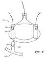
FIG. 2 , an exemplary method is shown for delivering a two-componentheart valve assembly 10, such as that described above. As shown, theheart valve assembly 10 may include agasket member 12 and avalve member 14 loaded into acatheter 60, thereby providing a system that may be used to deliver and/or implant theheart valve assembly 10 into abiological annulus 92,e.g., to replace a nativeaortic valve 94. In an exemplary embodiment, thegasket member 12 andvalve member 14 are disposed adjacent one another within alumen 62 of thecatheter 60 adjacent to adistal end 64, which may be tapered or otherwise sized and/or shaped to facilitate introduction into a patient's vasculature or other body lumens. - As shown, the
gasket member 12 is disposed immediately adjacent thedistal end 64 and thevalve member 14 is disposed proximal to thegasket member 12 such that thegasket member 12 andvalve member 14 may be delivered successively from thecatheter 60. Optionally, thecatheter 60 may include one or more pusher members (not shown) adjacent to thegasket member 12 and/orvalve member 14, which may be used to deploy thegasket member 12 and/orvalve member 14. For example, the pusher member(s) may include one or more tubular bodies or other structures (not shown) that restrain thegasket member 12 and/orvalve member 14 from axial movement when thecatheter 60 is retracted, thereby exposing thegasket member 12 andcrown 14 beyond thedistal end 64. - For example, a first pusher member may be provided that includes a distal end disposed adjacent the
gasket member 12, and a second pusher member may be provided that includes a distal end disposed adjacent thevalve member 14. The first pusher member may include a lumen, slot, or other feature for accommodating thevalve member 14 and/or second pusher member. Thus, if thecatheter 60 is withdrawn proximally while maintaining the first pusher member substantially stationary, thegasket member 12 may be deployed from thedistal end 64 of thecatheter 60, while the second pusher member andvalve member 14 move with thecatheter 60. Thereafter, thecatheter 60 may be withdrawn further proximally while maintaining the second pusher member substantially stationary, thevalve member 14 may be deployed from thedistal end 64 of thecatheter 60. Alternatively, a single pusher member may be provided that may carry thegasket member 12 andvalve member 14, thereby allowing thegasket member 12 andvalve member 14 to be deployed successively from thecatheter 60. - After manufacturing the components of the
heart valve assembly 10 andcatheter 60, the components may be loaded into thecatheter 60, e.g., during manufacturing or any time before delivery into a patient. In an exemplary embodiment, thegasket member 12 andvalve member 14 may be contracted or folded separately from each other and loaded successively into thecatheter 60, e.g., from thedistal end 64. If thecatheter 60 includes a pusher member for carrying the components, thegasket member 12 andvalve member 14 may be loaded onto the pusher member, which may then be inserted into thecatheter 60. One of the advantages of separating thegasket member 12 andvalve member 14 and loading them separately is that they may be folded or otherwise compressed to a smaller diameter or size than if folded after thegasket member 12 andvalve member 14 are attached to each other. Furthermore, folding thegasket member 12 andvalve member 14 separately may reduce stress on thegasket member 12 andvalve member 14 while contracted, which may improve durability of theheart valve assembly 10. - Guide elements (not shown) are loaded into the
catheter 60 during manufacturing and/or assembly. For example, if thegasket member 12 and/orvalve member 14 include tubular members or other features (not shown) for receiving the guide elements therethrough, the guide elements may be directed through the features before loading thegasket member 12 and/orvalve member 14 into thecatheter 60. The guide elements are directed through thecatheter 60, e.g., to the proximal end (not shown), e.g., such that the guide elements extend from the proximal end, through thevalve member 14 and/or gasket member 12 (e.g., through lumen 62) and to thedistal end 64 of thecatheter 60. The guide elements extend a predetermined distance out of thedistal end 64 of thecatheter 60, e.g., to provide sufficient length that may introduced into a patient before thecatheter 60. - Turning to
FIG. 2 , during use, theguide elements 96 are delivered and attached to tissue surrounding thebiological annulus 92. - In an exemplary embodiment, the
sutures 96 may be delivered from a percutaneous entry site, e.g., a puncture in the femoral, carotid, radial, or other artery, into the aortic root. From within the aortic root, the sutures may be driven through or otherwise secured to the tissue surrounding thebiological annulus 92. If desired, knots may be directed down thesutures 96 to the location where they are secured to the tissue surrounding thebiological annulus 92. Alternatively, thesutures 96 may include two ends that extend from thebiological annulus 92. Thus, thesutures 96 may extend from thebiological annulus 92, through any intervening vasculature to the percutaneous entry site, and out of the patient's body. - Once the
sutures 96 are in place, thecatheter 60 may be introduced through the percutaneous entry site, and advanced through the patient's vasculature over thesutures 96 into the aortic root. For example, free ends of thesutures 96 may be backloaded into thedistal end 64 of thecatheter 60, through thegasket member 12 and/orvalve member 14, and thecatheter 60 to the proximal end. Alternatively, as described above, thesutures 96 may be preloaded through thecatheter 60. Optionally, thecatheter 60 may be inserted through an introducer sheath or other device (not shown) at the entry site, using known procedures. - With the
distal end 64 of thecatheter 60 positioned adjacent or within thebiological annulus 92, thegasket member 12 may be deployed from thedistal end 64, e.g., by retracting thecatheter 60 partially and using a pusher member or otherwise preventing proximal movement of thegasket member 12. Upon being exposed within thebiological annulus 92, thegasket member 12 may resiliently return to its expanded or relaxed condition. Alternatively, thegasket member 12 may be expanded or "unfurled" as it is advanced distally along thesutures 96. In a further alternative, a tool (not shown) may be advanced over thesutures 96 or over thecatheter 60, which may be used to expand thegasket member 12. - The
gasket member 12 may then be seated within thebiological annulus 92. For example, the pusher member (not shown) may be advanced to direct thegasket member 12 over thesutures 96, e.g., into the site of thenative valve leaflets 94. If thenative valve leaflets 94 remain within thebiological annulus 92 during delivery, thegasket member 12 may deflect theleaflets 94 outwardly to open thebiological annulus 92. Optionally, thegasket member 12 may at least partially dilate thebiological annulus 92, similar to the methods in the applications identified above, e.g., because of the resilient bias of theannular ring 18 to expand radially outwardly. - For example, with the
annular ring 18 contracted into a relatively small diameter (if theannular ring 18 is radially compressible), thegasket member 12 may be advanced into thebiological annulus 92 using a delivery tool (not shown). Thegasket member 12 may be advanced until theannular ring 18 extends at least partially into thebiological annulus 92. In one embodiment, theannular ring 18 and/or other component of thegasket member 12 may extend entirely through the biological annulus, with the lower edge of theannular ring 18 remaining free within the sub-annular space below thebiological annulus 92. Optionally, thegasket member 12 may include a flexible skirt (not shown) that may extend below through thebiological annulus 92 when thegasket member 12 is secured. The skirt may be biased to extend outwardly, e.g., to provide a smooth transition and/or enhance a seal between theheart vale assembly 10 and thebiological annulus 92. - Similar to the embodiment shown in
FIG. 5B , thesewing cuff 20 may contact the tissue within the supra-annular space above thebiological annulus 92, although thesewing cuff 20 may not provide any structural support of theannular ring 18. - If the
annular ring 18 is expandable or otherwise compressed, theannular ring 18 may then be expanded within the biological annulus, e.g., to dilate the biological annulus or otherwise direct the surrounding tissue outwardly against the underlying tissue structures. Alternatively, a dilation tool (not shown) may be advanced into thegasket member 12 and expanded to forcibly (e.g., plastically) expand theannular ring 18 within thebiological annulus 92. As thegasket member 12 is delivered, thesewing cuff 20 may be released to allow thesewing cuff 20 to contact the surrounding tissue, e.g., within the aortic root above thebiological annulus 92. Optionally, thesewing cuff 20 may adopt the shape of the surrounding tissue, e.g., lying flatter within the coronary sinus regions, while becoming more vertical adjacent the commissures. - The
gasket member 12 may be secured within thebiological annulus 92 simply by the frictional engagement between theannular ring 18 and the surrounding tissue. Alternatively, theannular ring 18 and/orsewing cuff 20 may include one or engagement elements (not shown) that puncture or otherwise engage the surrounding tissue to enhance securing thegasket member 12. In a further alternative, a plurality of fasteners, e.g., clips, staples, sutures, and the like, may be directed through thesewing cuff 20 into the tissue surrounding thebiological annulus 92 to secure thegasket member 12 relative to thebiological annulus 92. - With continued reference to
FIG. 2 , thevalve member 14 may then be deployed from the catheter 60 (or from a separate delivery device after delivering fasteners through the gasket member 12) and advanced into thebiological annulus 92. For example, thevalve member 14 may be advanced over thesutures 96 until connectors on thegasket member 12 and/orvalve member 14 engage to secure thevalve member 14 to thegasket member 12. For example, thevalve member 14 and/orgasket member 12 may include one or more cooperating clips, detents, and the like that may self-engage when thevalve member 14 is docked against thesewing cuff 20 or otherwise into thegasket member 12, similar to the embodiments described in the applications identified above. - Alternatively, the
valve member 14 may be secured to thecollar 22, e.g., using one or more connectors on thevalve member 14 and/orcollar 22, e.g., a drawstring (not shown). In a further alternative, thesutures 96 may be used to secure thevalve member 14 to thegasket member 12, similar to the embodiment shown inFIGS. 3A and 3B and described further elsewhere herein. - Turning to
FIGS. 3A-3C , another embodiment of aheart valve assembly 110 is shown that includes agasket member 112 and a valve member orcrown 114, which may be constructed similar to the other embodiments described herein. In this embodiment, thegasket member 112 includes anannular ring 118, and asewing cuff 120, which may be similar to the previous embodiments. In addition, thegasket member 112 includes a plurality ofposts 124 extending upwardly, e.g., from theannular ring 118. - The
posts 124 may include passages, tubular elements, or other receivers (not shown) for receiving sutures orother filaments 196 therethrough. Alternatively, thesutures 196 may be attached to ends or other portions of theposts 124. In this alternative, thesutures 196 may include detents orother connectors 197 disposed a predetermined distance from the ends of theposts 124. For example, theconnectors 197 may be formed from plastic or metal components fixed to thesutures 196 and including ramped or tapered proximal surfaces and blunt distal surfaces or edges. In the embodiment shown inFIGS. 3A and 3B , theconnectors 197 are conical features. Alternatively, as shown inFIG. 4 , the connectors 197' may be ratcheting features, e.g., including harpoon tips and/or one or more, e.g., a plurality of one-way ratchets. - Returning to
FIGS. 3A-3C , thevalve member 114 includes asleeve 132, e.g., of bovine pericardium or other tissue, synthetic material, fabric, and the like, which may be formed to provide a plurality ofleaflets 133. Thesleeve 132 may also include a plurality of tubes orother receivers 134, which may be formed the same material as theleaflets 133, e.g., bovine pericardium, and/or other material, e.g., fabric. For example, thetubes 134 may be formed by bonding, stitching, and/or otherwise attaching portions of thesleeve 132 to create thetubes 134 betweenadjacent leaflets 133. Alternatively, thetubes 134 may be formed from separate material attached to thesleeve 132, e.g., cloth, silicone, and/or other material that may be flexible, for example, so that thetubes 134 may be folded and/or expanded easily. Thetubes 134 may be sized to be received over theposts 124 of thegasket member 112, as explained further below. - Optionally, the
valve member 114 may include acloth ring 136 at the base of thetubes 134, e.g., for providing a tissue ingrowth surface. Thecloth ring 136 may be formed from cloth and, optionally, may include a silicone or other core (not shown), which may be attached to thesleeve 132, e.g., by stitching, bonding, and the like. Thecloth ring 136 may provide an additional interface with thegasket member 112, e.g., to enhance sealing when thevalve member 114 is secured relative to thegasket member 112. - Turning to
FIGS. 5A-5C , thegasket member 112 andvalve member 114 may be loaded into acatheter 60, similar to the previous embodiments. Optionally, thecatheter 60 may include apusher member 63 adjacent to thegasket member 112 and/orvalve member 114, which may be used to deploy thegasket member 112 and/orvalve member 114, similar to embodiments described elsewhere herein. As shown inFIG. 5A , apusher wire 73 may be attached to thepusher member 63, which may extend proximally through thecatheter 60. Thepusher wire 73 may be coupled to an actuator, e.g., a slider, button, dial, or other feature (not shown), on a handle (also not shown) on the proximal end of thecatheter 60. Thus, the actuator andpusher wire 73 may be used to hold or push thepusher member 63 relative to thecatheter 60, e.g., along thecatheter lumen 62. - As shown in
FIG. 5A , with the components of heart valve assembly loaded in the catheter, thecatheter 60 may be advanced oversutures 196 previously attached to tissue surrounding thebiological annulus 92, e.g., as described above. Once thedistal end 64 of thecatheter 60 is disposed adjacent thebiological annulus 92, e.g., within the aortic root for aortic valve replacement, thegasket member 112 may be deployed from thecatheter 60 and advanced over thesutures 196 into thebiological annulus 92, similar to the methods described above. If thesutures 196 include theconnectors 197, such as those shown inFIGS. 3A-3C (and not shown inFIGS. 5A-5C ), thegasket member 112 may be advanced such that theconnectors 197 pass through passages or receivers in thegasket member 112. For example, the proximal end of the passages in thegasket member 112 may include a narrow region, one or more tabs, and the like (not shown) that may allow theconnectors 197 to pass through as thegasket member 112 is advanced, but prevent thegasket member 112 from being withdrawn back over theconnectors 197. Alternatively, thesutures 196 andconnectors 197 may simply pass through a portion of the fabric covering on thegasket member 112, e.g., covering thesewing cuff 120. - With the
gasket member 112 delivered into thebiological annulus 92, thevalve member 114 may be deployed from thecatheter 60, e.g., similar to the previous methods, and advanced over thesutures 196 until thevalve member 114 is docked to thegasket member 112. With additional reference toFIG. 3C , as thevalve member 114 is advanced over theconnectors 197, theconnectors 197 may pass through thetubes 134 of thevalve member 14 until theconnectors 197 exit from the proximal or upper ends of thetubes 134. This advancement may be facilitated by the ramped proximal surfaces of theconnectors 197. The blunt lower edges of theconnectors 197 may then abut the proximal ends of thetubes 134 or otherwise prevent thevalve member 114 from being removed back over theconnectors 197. Thus, thevalve member 114 may be substantially secured relative to thegasket member 112, e.g., against thegasket member 112, as shown inFIG. 3C . - The
excess suture material 196 above theconnectors 197 may then be removed, leaving thevalve member 114,gasket member 112, andconnectors 197, and sutures secured to the tissue within or adjacent thebiological annulus 92. For example, in one embodiment, thesutures 196 may include weakened or break-away areas, e.g., immediately above theconnectors 197 that may separate when a threshold tensile force is applied to thesutures 196. Alternatively, a cutter or other tool (not shown) may be advanced into the aortic root (or other region adjacent the biological annulus 92) and manipulated to cut or otherwise sever thesutures 196 above theconnectors 197. - One advantage with this embodiment is that the
crown 114 may simply be asleeve 132 formed from tissue, and may not include a frame, unlike the previous embodiments. This may facilitate rolling or otherwise contracting thecrown 114 into a delivery condition. In addition, the embodiment may eliminate any risk of metal or other frame components damaging tissue leaflets during contraction and/or expansion. Thus, theposts 124 on thegasket member 112 provide a frame-like support structure that supports thesleeve 132 and allows the leaflets of thesleeve 132 to open and close during beating of the heart. - In other embodiments, such as that shown in
FIG. 6 , posts 124' on a gasket member 112' may include detents, tabs, or other connectors 128' that may accommodate receiving a portion of avalve member 114,' e.g., tubes 134' over theposts 124.' The tubes 134' may include receptacles 138' that interlock or otherwise engage with the connectors 128' to secure the valve member 114' to thegasket member 112.' For example, as shown, the tabs 128' may present a tapered edge that allows the tubes 134' to pass freely over theposts 124,' yet is biased to resiliently return outwardly to prevent removal or other movement of the tubes 134' off of theposts 124.' The receptacles 138' receive the outwardly returned tabs 128'. - Turning to
FIGS. 7A and 7B , a valve member orcrown 214 is shown that includes anexpandable frame 232 that may be compressed inwardly into a delivery condition (shown inFIG. 7A ) and expandable to a deployed condition (shown inFIG. 7B ). As shown, thevalve member 214 may include an annular shaped body orframe 232, one ormore valve elements 233, and a base 232a. Thevalve member 214 is a bioprosthetic valve member, i.e., anannular frame 232 carrying a plurality oftissue leaflets 233 extending from theframe 232, e.g., attached tocommissures 234. Theframe 232 may have a noncircular, e.g., multiple lobular shape, such as a tri-lobular shape, including three lobes separated by cusps or scallops. Optionally, theframe 232 may include one or more connectors (not shown) for mating with a cooperating connector on a gasket member (also not shown), similar to other embodiments described elsewhere herein. - The
frame 232 and/or other components of thevalve member 214 may include a fabric covering 235, e.g., to enhance sealing and/or facilitate tissue ingrowth, which may be sutured or otherwise secured around, over, or otherwise to the component(s). The fabric covering 235 comprises a polyester material, e.g., Dacron. Theframe 232 may be formed from one or more rod elements, e.g., that have portions removed to provide a desired flexibility for theframe 232. An example uses a solid Nitinol bar that is machined using methods known in the art to create theframe 232, e.g., conventional machining, electrical discharge machining (EDM), laser, and water jet machining. Alternatively, theframe 232 may include astent member 236 attached to the base 232a of thevalve member 214 for increasing expandability of thevalve member 214 within a gasket member. Thestent member 236 may comprise materials similar to those described above for making annular rings, e.g., Nitinol or other elastic or superelastic material. - The
valve member 214 may include a plurality of struts (not shown) that may be attached to theframe 232 and/or otherwise carry leaflets orother valve elements 233. For example, the struts may include a laminate structure, similar to previous embodiments. Theleaflets 233 may be formed from tissue, such as bovine pericardium, also similar to previous embodiments. Alternatively, thevalve member 214 may be a connecting device to which avalve 233 may be connected or that may otherwise receive a valve component, as described elsewhere herein. In further alternatives, thevalve member 214 may include a mechanical valve or other valve (not shown), also as described elsewhere herein. - The
valve member 214 may be compressible into the delivery condition using avalve holder tool 270, shown inFIG. 7A , e.g., to facilitate introduction into a delivery catheter (not shown) and/or deployment from the delivery catheter. As shown inFIG. 7A , theframe 232 may be folded inwardly using thetool 270, bringing each of thecommissures 234 inwardly towards one another. For example, thetool 270 may include a central core member (not shown) including a plurality of lobes, and a plurality of movable arms disposed between adjacent lobes (also not shown). Theframe 232 may be disposed between the core member and the arms, and the arms may be directed inwardly to fold theframe 232, e.g., similar to tools disclosed inUS application Serial No. 60/746,038 . - With the
frame 232 folded or otherwise compressed, thetool 270 andvalve member 214 may be loaded into a delivery catheter (not shown). Thetool 270 may have an elongate flexible or semi-rigid body (not shown), which may extend through the delivery catheter, yet allow the delivery catheter to be advanced through a patient's vasculature. As shown inFIG. 7B , when it is desired to deploy thevalve member 214, e.g., within a biological annulus, thevalve member 214 and tool head may be advanced from the delivery catheter, and theframe 232 may be expanded, e.g., by releasing the arms or other actuator on the tool. Upon being released, theframe 232 may resiliently expand, e.g., thecommissures 234 may automatically separate from one another to open theleaflets 233. Thevalve member 214 may then be secured relative to a gasket member (not shown), similar to the other embodiments described elsewhere herein. - Turning to
FIG. 8A and 8B , shown are details of acommissure 234 that may be provided on theframe 232 of thevalve member 214 shown inFIGS. 7A and 7B . The frame 232 (or struts, not shown, attached to the frame 232) may include a plurality of holes or other commissure attachment points 237. Sutures or other connectors (not shown) may be directed through theholes 237 to attach a leaflet (also not shown) to thecommissure 234, similar to the previous embodiments. Optionally, the thickness of thecommissure 234 may be varied to provide a desired stiffness. For example, the tip of thecommissure 234 may be thinner than base portions of theframe 232, e.g., to allow greater flexibility of the tip of thecommissure 234 for upper edges of leaflets (not shown) attached to theframe 232. The plurality of commissure attachment points 237 provide alternative locations for attaching tissue leaflets (not shown) to theframe 232. FIGS. 9A and 9B show an example of aframe 232.' The frame 232' includes pairs of commissures 234' (one shown) spaced apart around the circumference of theframe 232,' each commissure including a plurality of holes or other commissure attachment points 237.' Each pair of commissures 234' may support edges of individual, adjacent leaflets (not shown) such that each leaflet is independently supported. The commissures 234' may be directed inwardly towards one another (as shown inFIG. 9A ) as the frame 232' is contracted to the delivery condition and may resiliently move away from one another (as shown inFIG. 9B ) when the frame 232' is released, e.g., during deployment and implantation of the heart valve assembly, similar to the previous embodiments.FIGS. 10A-11B show alternative constructions and methods for attaching leaflets to an expandable frame, e.g., to provide a valve member (not shown), such as those described elsewhere herein.FIGS. 10A and 10B show a portion of aframe 332 that includes acommissure 334 to which aleaflet 333 is attached. As best seen inFIG. 10B , the edges of theleaflets 333 may be received within achannel 334d formed in thecommissure 334, e.g., defined by twosides backside 334c. Theedges 333a of theleaflets 333 may abut into thechannel 334d. One or more sutures 396 (as seen inFIG. 10A ) may then be applied along asuture line 305, e.g., through theleaflets 333 and thecommissure 334, to secure theleaflets 333 to theframe 332. Thecommissure 334 may include one or more holes, slots, and the like (not shown), similar to those shown inFIGS. 8A-9B , for receiving thesutures 396 therethrough.- Turning to
FIGS. 11A and 11B , another construction and method for attaching leaflets to a frame is shown. As shown inFIG. 11A , a frame 332' may include a plurality of commissures 334' spaced apart around a circumference of theframe 332.' Each commissure 334' may include twosides 334a', 334b' and abackside 334c.' The twosides 334a', 334b' may extend upwardly beyond thebackside 334c,' thereby defining posts around which edges 333a' of valve leaflets 333' may be wrapped. Sutures 396' may then be applied along the suture line 305' to secure the leaflets 333' to theframe 332,' similar to the previous embodiments. - While the invention is susceptible to various modifications, and alternative forms, specific examples thereof have been shown in the drawings and are herein described in detail. It should be understood, however, that the invention is not to be limited to the particular forms or methods disclosed, but to the contrary, the invention is to cover all modifications, equivalents and alternatives falling within the scope of the appended claims.
Claims (17)
- A system for delivering a multiple component prosthetic valve into a biological annulus (92) within a patient's body, comprising:an elongate tubular member (60) comprising a proximal end, a distal end (64) sized for introduction into a body lumen, and a lumen (62) extending between the proximal and distal ends (64);a first annular prosthesis (12, 112, 112') implantable within the biological annulus (92), the annular prosthesis (12, 112, 112') being disposed within the tubular member adjacent the distal end in a contracted condition, the annular prosthesis (12, 112, 112') being expandable upon deployment from the tubular member within the biological annulus (92) to an enlarged condition; anda second valve prosthesis (14, 114, 114', 214) securable to the annular prosthesis (12, 112, 112'), the valve prosthesis (14, 114, 114', 214) being disposed within the tubular member adjacent the annular prosthesis (12, 112, 112') in a contracted condition, the valve prosthesis (14, 114, 114', 214) being expandable upon deployment from the tubular member within the biological annulus (92) such that the valve prosthesis (14, 114, 114', 214) may be secured to the annular prosthesis (12, 112, 112'),characterized in that the system further comprises a plurality of elongate guide elements (96) including a first end attachable to tissue surrounding a biological annulus (92) and having sufficient length to extend from the biological annulus (92) to a percutaneous entry site, the guide elements (96) being sized for being received through respective portions of at least one of the annular prosthesis (12, 112, 112') and the valve prosthesis (14, 114, 114', 214).
- The system of claim 1, further comprising a pusher member disposed within the tubular member (60), the pusher member adjacent at least one of the annular and valve prostheses, the pusher member being movable relative to the tubular member (60) for deploying at least one of the annular prosthesis (12) and the valve prosthesis (14).
- The system of claim 1, wherein the guide elements (96) are sized such that the tubular member (60) may be advanced through a body lumen of a patient over the guide elements (96).
- The system of claim 3, wherein the valve prosthesis (14) comprises a plurality of passages for receiving respective guide elements (96) therethrough such that the valve prosthesis (14) may be advanced over the guide elements (96).
- The system of claim 3, wherein the annular prosthesis (12) comprises a plurality of passages for receiving respective guide elements (96) therethrough such that the annular prosthesis (12) may be advanced over the guide elements (96).
- The system of claim 3, wherein each of the guide elements (196) comprises one or more connectors (197, 197') spaced apart from the first end for securing at least one of the annular prosthesis (112) and the valve prosthesis (114) relative to tissue to which the first end is attached.
- The system of claim 6, wherein the one or more connectors (197') comprise a ratchet.
- The system of claim 6, wherein the one or more connectors (197) comprise a ramped proximal surface and a blunt distal surface.
- The system of claim 1, wherein the valve prosthesis (14) comprises a frame (32), the frame (32) being compressible into a folded condition for at least partially contracting the valve member (14) into the contracted condition, and wherein the frame (32) is formed from resilient material such that, when the valve prosthesis (14) is deployed from the tubular member (60), the frame (32) resiliently expands to direct the valve prosthesis (14) towards the enlarged condition.
- The system of any preceding claim, wherein the valve prosthesis (114) comprises a flexible sleeve (132) comprising a plurality of leaflets (133), the sleeve (132) being contractible into the contracted condition.
- The system of claim 10, wherein the sleeve (132) further comprises a plurality of pockets (134), the annular prosthesis (112) further comprising a plurality of posts (124) sized for being received in respective pockets (134) of the sleeve (132) for at least partially securing the valve prosthesis (114) relative to the annular prosthesis (112).
- The system of claim 11, wherein the posts (124) and pockets (134) comprises cooperating connectors (197) for further securing the valve prosthesis (114) relative to the annular prosthesis (112).
- The system of claim 1, wherein the first annular prosthesis (14) comprises an annular ring (18) and a sewing cuff (20) extending outwardly from the annular ring (18), the annular prosthesis (12) being contractible into a contracted condition for introduction through a body lumen and being expandable for deployment within a biological annulus (92).
- The system of any preceding claim, further comprising one or more connectors (197) on at least one of the annular prosthesis (112) and the valve prosthesis (114) for securing the valve prosthesis (114) relative to the annular prosthesis (112).
- The system of any preceding claim, wherein the valve prosthesis (14) comprises a frame (32), the frame (32) being foldable into a folded condition for at least partially contracting the valve prosthesis (14) into the contracted condition.
- The system of any preceding claim, further comprising one or more fixturing elements for securing the valve prosthesis to the annular prosthesis.
- The system of claim 16, wherein the one or more fixturing elements comprise one or more filaments including connectors thereon.
Applications Claiming Priority (2)
| Application Number | Priority Date | Filing Date | Title |
|---|---|---|---|
| US69941605P | 2005-07-13 | 2005-07-13 | |
| PCT/US2006/027687WO2007009117A1 (en) | 2005-07-13 | 2006-07-13 | Two-piece percutaneous prosthetic heart valves and methods for making and using them |
Publications (2)
| Publication Number | Publication Date |
|---|---|
| EP1919397A1 EP1919397A1 (en) | 2008-05-14 |
| EP1919397B1true EP1919397B1 (en) | 2013-01-02 |
Family
ID=37102211
Family Applications (1)
| Application Number | Title | Priority Date | Filing Date |
|---|---|---|---|
| EP06787577ANot-in-forceEP1919397B1 (en) | 2005-07-13 | 2006-07-13 | Two-piece percutaneous prosthetic heart valves |
Country Status (3)
| Country | Link |
|---|---|
| US (1) | US20070016288A1 (en) |
| EP (1) | EP1919397B1 (en) |
| WO (1) | WO2007009117A1 (en) |
Cited By (23)
| Publication number | Priority date | Publication date | Assignee | Title |
|---|---|---|---|---|
| US9974647B2 (en) | 2014-06-12 | 2018-05-22 | Caisson Interventional, LLC | Two stage anchor and mitral valve assembly |
| US10080656B2 (en) | 2012-04-19 | 2018-09-25 | Caisson Interventional Llc | Heart valve assembly systems and methods |
| US10117741B2 (en) | 2013-10-23 | 2018-11-06 | Caisson Interventional, LLC | Methods and systems for heart valve therapy |
| US10265166B2 (en) | 2015-12-30 | 2019-04-23 | Caisson Interventional, LLC | Systems and methods for heart valve therapy |
| US10285810B2 (en) | 2012-04-19 | 2019-05-14 | Caisson Interventional, LLC | Valve replacement systems and methods |
| US10856984B2 (en) | 2017-08-25 | 2020-12-08 | Neovasc Tiara Inc. | Sequentially deployed transcatheter mitral valve prosthesis |
| US10940001B2 (en) | 2012-05-30 | 2021-03-09 | Neovasc Tiara Inc. | Methods and apparatus for loading a prosthesis onto a delivery system |
| US11311376B2 (en) | 2019-06-20 | 2022-04-26 | Neovase Tiara Inc. | Low profile prosthetic mitral valve |
| US11357622B2 (en) | 2016-01-29 | 2022-06-14 | Neovase Tiara Inc. | Prosthetic valve for avoiding obstruction of outflow |
| US11389291B2 (en) | 2013-04-04 | 2022-07-19 | Neovase Tiara Inc. | Methods and apparatus for delivering a prosthetic valve to a beating heart |
| US11413139B2 (en) | 2011-11-23 | 2022-08-16 | Neovasc Tiara Inc. | Sequentially deployed transcatheter mitral valve prosthesis |
| US11419720B2 (en) | 2010-05-05 | 2022-08-23 | Neovasc Tiara Inc. | Transcatheter mitral valve prosthesis |
| US11439506B2 (en) | 2014-10-23 | 2022-09-13 | Caisson Interventional Llc | Systems and methods for heart valve therapy |
| US11464631B2 (en) | 2016-11-21 | 2022-10-11 | Neovasc Tiara Inc. | Methods and systems for rapid retraction of a transcatheter heart valve delivery system |
| US11491006B2 (en) | 2019-04-10 | 2022-11-08 | Neovasc Tiara Inc. | Prosthetic valve with natural blood flow |
| US11497602B2 (en) | 2012-02-14 | 2022-11-15 | Neovasc Tiara Inc. | Methods and apparatus for engaging a valve prosthesis with tissue |
| US11602429B2 (en) | 2019-04-01 | 2023-03-14 | Neovasc Tiara Inc. | Controllably deployable prosthetic valve |
| US11737872B2 (en) | 2018-11-08 | 2023-08-29 | Neovasc Tiara Inc. | Ventricular deployment of a transcatheter mitral valve prosthesis |
| US11779742B2 (en) | 2019-05-20 | 2023-10-10 | Neovasc Tiara Inc. | Introducer with hemostasis mechanism |
| US11944537B2 (en) | 2017-01-24 | 2024-04-02 | 4C Medical Technologies, Inc. | Systems, methods and devices for two-step delivery and implantation of prosthetic heart valve |
| US11998447B2 (en) | 2019-03-08 | 2024-06-04 | Neovasc Tiara Inc. | Retrievable prosthesis delivery system |
| US12029647B2 (en) | 2017-03-07 | 2024-07-09 | 4C Medical Technologies, Inc. | Systems, methods and devices for prosthetic heart valve with single valve leaflet |
| US12109111B2 (en) | 2015-12-15 | 2024-10-08 | Neovasc Tiara Inc. | Transseptal delivery system |
Families Citing this family (312)
| Publication number | Priority date | Publication date | Assignee | Title |
|---|---|---|---|---|
| US8366769B2 (en) | 2000-06-01 | 2013-02-05 | Edwards Lifesciences Corporation | Low-profile, pivotable heart valve sewing ring |
| US6409758B2 (en)* | 2000-07-27 | 2002-06-25 | Edwards Lifesciences Corporation | Heart valve holder for constricting the valve commissures and methods of use |
| US7201771B2 (en) | 2001-12-27 | 2007-04-10 | Arbor Surgical Technologies, Inc. | Bioprosthetic heart valve |
| US7959674B2 (en)* | 2002-07-16 | 2011-06-14 | Medtronic, Inc. | Suture locking assembly and method of use |
| US8551162B2 (en) | 2002-12-20 | 2013-10-08 | Medtronic, Inc. | Biologically implantable prosthesis |
| US8021421B2 (en)* | 2003-08-22 | 2011-09-20 | Medtronic, Inc. | Prosthesis heart valve fixturing device |
| US7556647B2 (en)* | 2003-10-08 | 2009-07-07 | Arbor Surgical Technologies, Inc. | Attachment device and methods of using the same |
| US8603160B2 (en) | 2003-12-23 | 2013-12-10 | Sadra Medical, Inc. | Method of using a retrievable heart valve anchor with a sheath |
| US11278398B2 (en) | 2003-12-23 | 2022-03-22 | Boston Scientific Scimed, Inc. | Methods and apparatus for endovascular heart valve replacement comprising tissue grasping elements |
| US7959666B2 (en) | 2003-12-23 | 2011-06-14 | Sadra Medical, Inc. | Methods and apparatus for endovascularly replacing a heart valve |
| US8840663B2 (en) | 2003-12-23 | 2014-09-23 | Sadra Medical, Inc. | Repositionable heart valve method |
| US20050137687A1 (en) | 2003-12-23 | 2005-06-23 | Sadra Medical | Heart valve anchor and method |
| US8828078B2 (en) | 2003-12-23 | 2014-09-09 | Sadra Medical, Inc. | Methods and apparatus for endovascular heart valve replacement comprising tissue grasping elements |
| US7381219B2 (en) | 2003-12-23 | 2008-06-03 | Sadra Medical, Inc. | Low profile heart valve and delivery system |
| US9526609B2 (en) | 2003-12-23 | 2016-12-27 | Boston Scientific Scimed, Inc. | Methods and apparatus for endovascularly replacing a patient's heart valve |
| US20120041550A1 (en) | 2003-12-23 | 2012-02-16 | Sadra Medical, Inc. | Methods and Apparatus for Endovascular Heart Valve Replacement Comprising Tissue Grasping Elements |
| US8579962B2 (en) | 2003-12-23 | 2013-11-12 | Sadra Medical, Inc. | Methods and apparatus for performing valvuloplasty |
| US8287584B2 (en)* | 2005-11-14 | 2012-10-16 | Sadra Medical, Inc. | Medical implant deployment tool |
| US7871435B2 (en) | 2004-01-23 | 2011-01-18 | Edwards Lifesciences Corporation | Anatomically approximate prosthetic mitral heart valve |
| US20070073387A1 (en)* | 2004-02-27 | 2007-03-29 | Forster David C | Prosthetic Heart Valves, Support Structures And Systems And Methods For Implanting The Same |
| ITTO20040135A1 (en) | 2004-03-03 | 2004-06-03 | Sorin Biomedica Cardio Spa | CARDIAC VALVE PROSTHESIS |
| JP2007535342A (en) | 2004-03-11 | 2007-12-06 | パーキュテイニアス カルディオバスキュラー ソリューションズ ピー・ティー・ワイ リミテッド | Percutaneous prosthetic heart valve |
| US20050228494A1 (en)* | 2004-03-29 | 2005-10-13 | Salvador Marquez | Controlled separation heart valve frame |
| DE102005003632A1 (en) | 2005-01-20 | 2006-08-17 | Fraunhofer-Gesellschaft zur Förderung der angewandten Forschung e.V. | Catheter for the transvascular implantation of heart valve prostheses |
| US8096303B2 (en) | 2005-02-08 | 2012-01-17 | Koninklijke Philips Electronics N.V | Airway implants and methods and devices for insertion and retrieval |
| US8371307B2 (en) | 2005-02-08 | 2013-02-12 | Koninklijke Philips Electronics N.V. | Methods and devices for the treatment of airway obstruction, sleep apnea and snoring |
| US8574257B2 (en)* | 2005-02-10 | 2013-11-05 | Edwards Lifesciences Corporation | System, device, and method for providing access in a cardiovascular environment |
| ITTO20050074A1 (en) | 2005-02-10 | 2006-08-11 | Sorin Biomedica Cardio Srl | CARDIAC VALVE PROSTHESIS |
| US8608797B2 (en) | 2005-03-17 | 2013-12-17 | Valtech Cardio Ltd. | Mitral valve treatment techniques |
| US7513909B2 (en)* | 2005-04-08 | 2009-04-07 | Arbor Surgical Technologies, Inc. | Two-piece prosthetic valves with snap-in connection and methods for use |
| US8333777B2 (en) | 2005-04-22 | 2012-12-18 | Benvenue Medical, Inc. | Catheter-based tissue remodeling devices and methods |
| JP4912395B2 (en) | 2005-05-24 | 2012-04-11 | エドワーズ ライフサイエンシーズ コーポレイション | Rapid placement prosthetic heart valve |
| US8211169B2 (en) | 2005-05-27 | 2012-07-03 | Medtronic, Inc. | Gasket with collar for prosthetic heart valves and methods for using them |
| US8951285B2 (en) | 2005-07-05 | 2015-02-10 | Mitralign, Inc. | Tissue anchor, anchoring system and methods of using the same |
| US7776084B2 (en)* | 2005-07-13 | 2010-08-17 | Edwards Lifesciences Corporation | Prosthetic mitral heart valve having a contoured sewing ring |
| US20070213813A1 (en) | 2005-12-22 | 2007-09-13 | Symetis Sa | Stent-valves for valve replacement and associated methods and systems for surgery |
| US7967857B2 (en)* | 2006-01-27 | 2011-06-28 | Medtronic, Inc. | Gasket with spring collar for prosthetic heart valves and methods for making and using them |
| EP1988851A2 (en) | 2006-02-14 | 2008-11-12 | Sadra Medical, Inc. | Systems and methods for delivering a medical implant |
| US7749249B2 (en) | 2006-02-21 | 2010-07-06 | Kardium Inc. | Method and device for closing holes in tissue |
| US7749266B2 (en)* | 2006-02-27 | 2010-07-06 | Aortx, Inc. | Methods and devices for delivery of prosthetic heart valves and other prosthetics |
| JP5102279B2 (en)* | 2006-03-10 | 2012-12-19 | メドトロニック,インコーポレイテッド | Artificial valve introducer, method for producing the same and method for using the same |
| JP2009535128A (en)* | 2006-04-29 | 2009-10-01 | アーバー・サージカル・テクノロジーズ・インコーポレイテッド | Multi-part prosthetic heart valve assembly and apparatus and method for delivering the same |
| US8021161B2 (en)* | 2006-05-01 | 2011-09-20 | Edwards Lifesciences Corporation | Simulated heart valve root for training and testing |
| US8449605B2 (en) | 2006-06-28 | 2013-05-28 | Kardium Inc. | Method for anchoring a mitral valve |
| US20080004696A1 (en)* | 2006-06-29 | 2008-01-03 | Valvexchange Inc. | Cardiovascular valve assembly with resizable docking station |
| US7837610B2 (en) | 2006-08-02 | 2010-11-23 | Kardium Inc. | System for improving diastolic dysfunction |
| US20100087918A1 (en)* | 2006-10-23 | 2010-04-08 | Ivan Vesely | Cardiovascular valve and assembly |
| US9883943B2 (en) | 2006-12-05 | 2018-02-06 | Valtech Cardio, Ltd. | Implantation of repair devices in the heart |
| US11259924B2 (en) | 2006-12-05 | 2022-03-01 | Valtech Cardio Ltd. | Implantation of repair devices in the heart |
| AU2007330338A1 (en) | 2006-12-05 | 2008-06-12 | Valtech Cardio, Ltd. | Segmented ring placement |
| US20080208327A1 (en)* | 2007-02-27 | 2008-08-28 | Rowe Stanton J | Method and apparatus for replacing a prosthetic valve |
| US8092523B2 (en)* | 2007-03-12 | 2012-01-10 | St. Jude Medical, Inc. | Prosthetic heart valves with flexible leaflets |
| US11660190B2 (en) | 2007-03-13 | 2023-05-30 | Edwards Lifesciences Corporation | Tissue anchors, systems and methods, and devices |
| US7896915B2 (en) | 2007-04-13 | 2011-03-01 | Jenavalve Technology, Inc. | Medical device for treating a heart valve insufficiency |
| DE102007043830A1 (en) | 2007-09-13 | 2009-04-02 | Lozonschi, Lucian, Madison | Heart valve stent |
| US9848981B2 (en) | 2007-10-12 | 2017-12-26 | Mayo Foundation For Medical Education And Research | Expandable valve prosthesis with sealing mechanism |
| BR112012021347A2 (en) | 2008-02-26 | 2019-09-24 | Jenavalve Tecnology Inc | stent for positioning and anchoring a valve prosthesis at an implantation site in a patient's heart |
| US9044318B2 (en) | 2008-02-26 | 2015-06-02 | Jenavalve Technology Gmbh | Stent for the positioning and anchoring of a valvular prosthesis |
| US8382829B1 (en) | 2008-03-10 | 2013-02-26 | Mitralign, Inc. | Method to reduce mitral regurgitation by cinching the commissure of the mitral valve |
| US8696743B2 (en)* | 2008-04-23 | 2014-04-15 | Medtronic, Inc. | Tissue attachment devices and methods for prosthetic heart valves |
| US20090287304A1 (en)* | 2008-05-13 | 2009-11-19 | Kardium Inc. | Medical Device for Constricting Tissue or a Bodily Orifice, for example a mitral valve |
| EP2119417B2 (en) | 2008-05-16 | 2020-04-29 | Sorin Group Italia S.r.l. | Atraumatic prosthetic heart valve prosthesis |
| US8323337B2 (en)* | 2008-06-05 | 2012-12-04 | Medtronic, Inc. | Connection systems for two piece prosthetic heart valve assemblies and methods for making and using them |
| EP2296744B1 (en) | 2008-06-16 | 2019-07-31 | Valtech Cardio, Ltd. | Annuloplasty devices |
| EP2815724B2 (en) | 2008-07-15 | 2024-03-13 | St. Jude Medical, Inc. | Collapsible and re-expandable prosthetic heart valve cuff designs and complementary technological applications |
| WO2010030859A1 (en) | 2008-09-12 | 2010-03-18 | Valvexchange Inc. | Valve assembly with exchangeable valve member and a tool set for exchanging the valve member |
| EP3238661B1 (en) | 2008-10-10 | 2019-05-22 | Boston Scientific Scimed, Inc. | Medical devices and delivery systems for delivering medical devices |
| US8449625B2 (en) | 2009-10-27 | 2013-05-28 | Edwards Lifesciences Corporation | Methods of measuring heart valve annuluses for valve replacement |
| EP3613383B1 (en)* | 2008-11-21 | 2023-08-30 | Percutaneous Cardiovascular Solutions Pty Limited | Heart valve prosthesis |
| EP2370138B1 (en) | 2008-11-25 | 2020-12-30 | Edwards Lifesciences Corporation | Apparatus for in situ expansion of prosthetic device |
| US8308798B2 (en) | 2008-12-19 | 2012-11-13 | Edwards Lifesciences Corporation | Quick-connect prosthetic heart valve and methods |
| US8926697B2 (en) | 2011-06-23 | 2015-01-06 | Valtech Cardio, Ltd. | Closed band for percutaneous annuloplasty |
| US9011530B2 (en) | 2008-12-22 | 2015-04-21 | Valtech Cardio, Ltd. | Partially-adjustable annuloplasty structure |
| US8911494B2 (en) | 2009-05-04 | 2014-12-16 | Valtech Cardio, Ltd. | Deployment techniques for annuloplasty ring |
| US8241351B2 (en) | 2008-12-22 | 2012-08-14 | Valtech Cardio, Ltd. | Adjustable partial annuloplasty ring and mechanism therefor |
| US8940044B2 (en) | 2011-06-23 | 2015-01-27 | Valtech Cardio, Ltd. | Closure element for use with an annuloplasty structure |
| US10517719B2 (en) | 2008-12-22 | 2019-12-31 | Valtech Cardio, Ltd. | Implantation of repair devices in the heart |
| US8715342B2 (en) | 2009-05-07 | 2014-05-06 | Valtech Cardio, Ltd. | Annuloplasty ring with intra-ring anchoring |
| WO2010073246A2 (en) | 2008-12-22 | 2010-07-01 | Valtech Cardio, Ltd. | Adjustable annuloplasty devices and adjustment mechanisms therefor |
| EP2682072A1 (en) | 2008-12-23 | 2014-01-08 | Sorin Group Italia S.r.l. | Expandable prosthetic valve having anchoring appendages |
| US20100174363A1 (en)* | 2009-01-07 | 2010-07-08 | Endovalve, Inc. | One Piece Prosthetic Valve Support Structure and Related Assemblies |
| US9402720B2 (en)* | 2009-01-12 | 2016-08-02 | Valve Medical Ltd. | Modular percutaneous valve structure and delivery method |
| US9681950B2 (en)* | 2009-01-12 | 2017-06-20 | Valve Medical Ltd. | System and method for placing a percutaneous valve device |
| US8998982B2 (en)* | 2009-01-12 | 2015-04-07 | Valve Medical Ltd. | Method and apparatus for fine adjustment of a percutaneous valve structure |
| US8353956B2 (en) | 2009-02-17 | 2013-01-15 | Valtech Cardio, Ltd. | Actively-engageable movement-restriction mechanism for use with an annuloplasty structure |
| US9980818B2 (en) | 2009-03-31 | 2018-05-29 | Edwards Lifesciences Corporation | Prosthetic heart valve system with positioning markers |
| US9968452B2 (en) | 2009-05-04 | 2018-05-15 | Valtech Cardio, Ltd. | Annuloplasty ring delivery cathethers |
| US8348998B2 (en)* | 2009-06-26 | 2013-01-08 | Edwards Lifesciences Corporation | Unitary quick connect prosthetic heart valve and deployment system and methods |
| US10034748B2 (en) | 2009-09-18 | 2018-07-31 | The Regents Of The University Of California | Endovascular prosthetic heart valve replacement |
| WO2011041571A2 (en) | 2009-10-01 | 2011-04-07 | Kardium Inc. | Medical device, kit and method for constricting tissue or a bodily orifice, for example, a mitral valve |
| US9011520B2 (en) | 2009-10-29 | 2015-04-21 | Valtech Cardio, Ltd. | Tissue anchor for annuloplasty device |
| US9180007B2 (en) | 2009-10-29 | 2015-11-10 | Valtech Cardio, Ltd. | Apparatus and method for guide-wire based advancement of an adjustable implant |
| US10098737B2 (en) | 2009-10-29 | 2018-10-16 | Valtech Cardio, Ltd. | Tissue anchor for annuloplasty device |
| US8734467B2 (en) | 2009-12-02 | 2014-05-27 | Valtech Cardio, Ltd. | Delivery tool for implantation of spool assembly coupled to a helical anchor |
| EP3300695B1 (en) | 2009-12-08 | 2023-05-24 | Avalon Medical Ltd. | Device and system for transcatheter mitral valve replacement |
| US8870950B2 (en)* | 2009-12-08 | 2014-10-28 | Mitral Tech Ltd. | Rotation-based anchoring of an implant |
| EA201892282A1 (en)* | 2010-01-12 | 2019-07-31 | Вэлв Медикал Лтд | INSERTED THROUGH THE SKIN MODULAR VALVE STRUCTURE AND METHOD OF DELIVERY |
| EA201990753A1 (en)* | 2010-01-12 | 2019-12-30 | Вэлв Медикал Лтд | METHOD AND DEVICE FOR FINE ADJUSTMENT OF THE VALVE STRUCTURE ENTERED THROUGH THE SKIN |
| JP5627602B2 (en)* | 2010-01-12 | 2014-11-19 | バルブ メディカル エルティーディーValve Medical Ltd | System and method for deploying a percutaneous valve device |
| US9504562B2 (en)* | 2010-01-12 | 2016-11-29 | Valve Medical Ltd. | Self-assembling modular percutaneous valve and methods of folding, assembly and delivery |
| US8961596B2 (en) | 2010-01-22 | 2015-02-24 | 4Tech Inc. | Method and apparatus for tricuspid valve repair using tension |
| US10058323B2 (en) | 2010-01-22 | 2018-08-28 | 4 Tech Inc. | Tricuspid valve repair using tension |
| US8475525B2 (en) | 2010-01-22 | 2013-07-02 | 4Tech Inc. | Tricuspid valve repair using tension |
| US9307980B2 (en) | 2010-01-22 | 2016-04-12 | 4Tech Inc. | Tricuspid valve repair using tension |
| US8795354B2 (en)* | 2010-03-05 | 2014-08-05 | Edwards Lifesciences Corporation | Low-profile heart valve and delivery system |
| US20110224785A1 (en)* | 2010-03-10 | 2011-09-15 | Hacohen Gil | Prosthetic mitral valve with tissue anchors |
| SE535140C2 (en) | 2010-03-25 | 2012-04-24 | Jan Otto Solem | An implantable device, kit and system for improving cardiac function, including means for generating longitudinal movement of the mitral valve |
| US8986374B2 (en) | 2010-05-10 | 2015-03-24 | Edwards Lifesciences Corporation | Prosthetic heart valve |
| US9554901B2 (en) | 2010-05-12 | 2017-01-31 | Edwards Lifesciences Corporation | Low gradient prosthetic heart valve |
| US10856978B2 (en) | 2010-05-20 | 2020-12-08 | Jenavalve Technology, Inc. | Catheter system |
| IT1400327B1 (en) | 2010-05-21 | 2013-05-24 | Sorin Biomedica Cardio Srl | SUPPORT DEVICE FOR VALVULAR PROSTHESIS AND CORRESPONDING CORRESPONDENT. |
| WO2011147849A1 (en) | 2010-05-25 | 2011-12-01 | Jenavalve Technology Inc. | Prosthetic heart valve and transcatheter delivered endoprosthesis comprising a prosthetic heart valve and a stent |
| AU2011275468B2 (en) | 2010-07-09 | 2014-02-06 | Highlife Sas | Transcatheter atrio-ventricular valve prosthesis |
| US11653910B2 (en) | 2010-07-21 | 2023-05-23 | Cardiovalve Ltd. | Helical anchor implantation |
| US9132009B2 (en) | 2010-07-21 | 2015-09-15 | Mitraltech Ltd. | Guide wires with commissural anchors to advance a prosthetic valve |
| US9763657B2 (en) | 2010-07-21 | 2017-09-19 | Mitraltech Ltd. | Techniques for percutaneous mitral valve replacement and sealing |
| US8992604B2 (en) | 2010-07-21 | 2015-03-31 | Mitraltech Ltd. | Techniques for percutaneous mitral valve replacement and sealing |
| US9370418B2 (en) | 2010-09-10 | 2016-06-21 | Edwards Lifesciences Corporation | Rapidly deployable surgical heart valves |
| AU2011300644B2 (en) | 2010-09-10 | 2015-08-20 | Symetis Sa | Valve replacement devices and a system comprising the valve replacement device and a delivery device therefor |
| US8641757B2 (en) | 2010-09-10 | 2014-02-04 | Edwards Lifesciences Corporation | Systems for rapidly deploying surgical heart valves |
| US9125741B2 (en) | 2010-09-10 | 2015-09-08 | Edwards Lifesciences Corporation | Systems and methods for ensuring safe and rapid deployment of prosthetic heart valves |
| US10321998B2 (en)* | 2010-09-23 | 2019-06-18 | Transmural Systems Llc | Methods and systems for delivering prostheses using rail techniques |
| US9579193B2 (en) | 2010-09-23 | 2017-02-28 | Transmural Systems Llc | Methods and systems for delivering prostheses using rail techniques |
| US8845720B2 (en) | 2010-09-27 | 2014-09-30 | Edwards Lifesciences Corporation | Prosthetic heart valve frame with flexible commissures |
| US8940002B2 (en) | 2010-09-30 | 2015-01-27 | Kardium Inc. | Tissue anchor system |
| US8615310B2 (en)* | 2010-12-13 | 2013-12-24 | Pacesetter, Inc. | Delivery catheter systems and methods |
| EP2658480B1 (en)* | 2010-12-29 | 2017-11-01 | Neochord Inc. | Exchangeable system for minimally invasive beating heart repair of heart valve leaflets |
| EP2486894B1 (en) | 2011-02-14 | 2021-06-09 | Sorin Group Italia S.r.l. | Sutureless anchoring device for cardiac valve prostheses |
| ES2641902T3 (en) | 2011-02-14 | 2017-11-14 | Sorin Group Italia S.R.L. | Sutureless anchoring device for cardiac valve prostheses |
| US9072511B2 (en) | 2011-03-25 | 2015-07-07 | Kardium Inc. | Medical kit for constricting tissue or a bodily orifice, for example, a mitral valve |
| US8945209B2 (en) | 2011-05-20 | 2015-02-03 | Edwards Lifesciences Corporation | Encapsulated heart valve |
| US10500038B1 (en)* | 2011-05-20 | 2019-12-10 | Tel Hashomer Medical Research Infrastructure And Services Ltd. | Prosthetic mitral valve, and methods and devices for deploying the prosthetic mitral valve |
| JP5872692B2 (en)* | 2011-06-21 | 2016-03-01 | トゥエルヴ, インコーポレイテッド | Artificial therapy device |
| US10792152B2 (en) | 2011-06-23 | 2020-10-06 | Valtech Cardio, Ltd. | Closed band for percutaneous annuloplasty |
| EP3345573B1 (en) | 2011-06-23 | 2020-01-29 | Valtech Cardio, Ltd. | Closure element for use with annuloplasty structure |
| US9918840B2 (en) | 2011-06-23 | 2018-03-20 | Valtech Cardio, Ltd. | Closed band for percutaneous annuloplasty |
| EP2734157B1 (en)* | 2011-07-21 | 2018-09-05 | 4Tech Inc. | Apparatus for tricuspid valve repair using tension |
| US8852272B2 (en) | 2011-08-05 | 2014-10-07 | Mitraltech Ltd. | Techniques for percutaneous mitral valve replacement and sealing |
| EP2739214B1 (en) | 2011-08-05 | 2018-10-10 | Cardiovalve Ltd | Percutaneous mitral valve replacement and sealing |
| US20140324164A1 (en) | 2011-08-05 | 2014-10-30 | Mitraltech Ltd. | Techniques for percutaneous mitral valve replacement and sealing |
| WO2013021374A2 (en) | 2011-08-05 | 2013-02-14 | Mitraltech Ltd. | Techniques for percutaneous mitral valve replacement and sealing |
| EP4289398A3 (en) | 2011-08-11 | 2024-03-13 | Tendyne Holdings, Inc. | Improvements for prosthetic valves and related inventions |
| US9549817B2 (en) | 2011-09-22 | 2017-01-24 | Transmural Systems Llc | Devices, systems and methods for repairing lumenal systems |
| EA201400478A1 (en) | 2011-10-19 | 2014-10-30 | Твелв, Инк. | DEVICES, SYSTEMS AND METHODS OF PROTESIZING THE HEART VALVE |
| US9039757B2 (en) | 2011-10-19 | 2015-05-26 | Twelve, Inc. | Prosthetic heart valve devices, prosthetic mitral valves and associated systems and methods |
| US11202704B2 (en) | 2011-10-19 | 2021-12-21 | Twelve, Inc. | Prosthetic heart valve devices, prosthetic mitral valves and associated systems and methods |
| JP6133309B2 (en) | 2011-10-19 | 2017-05-24 | トゥエルヴ, インコーポレイテッド | Prosthetic heart valve device |
| US8858623B2 (en) | 2011-11-04 | 2014-10-14 | Valtech Cardio, Ltd. | Implant having multiple rotational assemblies |
| EP3656434B1 (en) | 2011-11-08 | 2021-10-20 | Valtech Cardio, Ltd. | Controlled steering functionality for implant-delivery tool |
| EP2881083B1 (en) | 2011-12-12 | 2017-03-22 | David Alon | Heart valve repair device |
| US9827092B2 (en) | 2011-12-16 | 2017-11-28 | Tendyne Holdings, Inc. | Tethers for prosthetic mitral valve |
| US9078747B2 (en) | 2011-12-21 | 2015-07-14 | Edwards Lifesciences Corporation | Anchoring device for replacing or repairing a heart valve |
| ES2752453T3 (en) | 2011-12-21 | 2020-04-06 | Univ Pennsylvania | Platforms for mitral valve replacement |
| US11207176B2 (en) | 2012-03-22 | 2021-12-28 | Boston Scientific Scimed, Inc. | Transcatheter stent-valves and methods, systems and devices for addressing para-valve leakage |
| US20130274873A1 (en) | 2012-03-22 | 2013-10-17 | Symetis Sa | Transcatheter Stent-Valves and Methods, Systems and Devices for Addressing Para-Valve Leakage |
| AU2013261169B2 (en) | 2012-05-15 | 2016-05-26 | Valve Medical Ltd | System and method for assembling a folded percutaneous valve |
| JP6219377B2 (en) | 2012-05-20 | 2017-10-25 | テル ハショマー メディカル リサーチ インフラストラクチャー アンド サーヴィシーズ リミテッド | Artificial mitral valve |
| CA2875669C (en)* | 2012-07-12 | 2017-02-14 | Boston Scientific Scimed, Inc. | Low profile heart valve delivery system and method |
| WO2014022124A1 (en) | 2012-07-28 | 2014-02-06 | Tendyne Holdings, Inc. | Improved multi-component designs for heart valve retrieval device, sealing structures and stent assembly |
| WO2014021905A1 (en) | 2012-07-30 | 2014-02-06 | Tendyne Holdings, Inc. | Improved delivery systems and methods for transcatheter prosthetic valves |
| US9693862B2 (en) | 2012-07-31 | 2017-07-04 | Edwards Lifesciences Corporation | Holders for prosthetic heart valves |
| US10543088B2 (en) | 2012-09-14 | 2020-01-28 | Boston Scientific Scimed, Inc. | Mitral valve inversion prostheses |
| US10849755B2 (en) | 2012-09-14 | 2020-12-01 | Boston Scientific Scimed, Inc. | Mitral valve inversion prostheses |
| US9216018B2 (en) | 2012-09-29 | 2015-12-22 | Mitralign, Inc. | Plication lock delivery system and method of use thereof |
| WO2014064694A2 (en) | 2012-10-23 | 2014-05-01 | Valtech Cardio, Ltd. | Controlled steering functionality for implant-delivery tool |
| EP2911593B1 (en) | 2012-10-23 | 2020-03-25 | Valtech Cardio, Ltd. | Percutaneous tissue anchor techniques |
| US12053378B2 (en) | 2012-11-07 | 2024-08-06 | Transmural Systems Llc | Devices, systems and methods for repairing lumenal systems |
| WO2014087402A1 (en) | 2012-12-06 | 2014-06-12 | Valtech Cardio, Ltd. | Techniques for guide-wire based advancement of a tool |
| CN105007832B (en) | 2013-01-09 | 2018-01-23 | 4科技有限公司 | Organize ancora equipment |
| US20150351906A1 (en) | 2013-01-24 | 2015-12-10 | Mitraltech Ltd. | Ventricularly-anchored prosthetic valves |
| EP2961351B1 (en) | 2013-02-26 | 2018-11-28 | Mitralign, Inc. | Devices for percutaneous tricuspid valve repair |
| US9907681B2 (en) | 2013-03-14 | 2018-03-06 | 4Tech Inc. | Stent with tether interface |
| US10449333B2 (en) | 2013-03-14 | 2019-10-22 | Valtech Cardio, Ltd. | Guidewire feeder |
| CN105283214B (en) | 2013-03-15 | 2018-10-16 | 北京泰德制药股份有限公司 | Translate conduit, system and its application method |
| WO2014145811A1 (en) | 2013-03-15 | 2014-09-18 | Edwards Lifesciences Corporation | Valved aortic conduits |
| US11007058B2 (en) | 2013-03-15 | 2021-05-18 | Edwards Lifesciences Corporation | Valved aortic conduits |
| US10463489B2 (en) | 2013-04-02 | 2019-11-05 | Tendyne Holdings, Inc. | Prosthetic heart valve and systems and methods for delivering the same |
| US11224510B2 (en) | 2013-04-02 | 2022-01-18 | Tendyne Holdings, Inc. | Prosthetic heart valve and systems and methods for delivering the same |
| US9486306B2 (en)* | 2013-04-02 | 2016-11-08 | Tendyne Holdings, Inc. | Inflatable annular sealing device for prosthetic mitral valve |
| US10478293B2 (en) | 2013-04-04 | 2019-11-19 | Tendyne Holdings, Inc. | Retrieval and repositioning system for prosthetic heart valve |
| US9610159B2 (en) | 2013-05-30 | 2017-04-04 | Tendyne Holdings, Inc. | Structural members for prosthetic mitral valves |
| US9468527B2 (en) | 2013-06-12 | 2016-10-18 | Edwards Lifesciences Corporation | Cardiac implant with integrated suture fasteners |
| CN105658178B (en) | 2013-06-25 | 2018-05-08 | 坦迪尼控股股份有限公司 | Thrombus management and structural compliance features for prosthetic heart valves |
| AU2014296087B2 (en) | 2013-08-01 | 2019-08-01 | Tendyne Holdings, Inc. | Epicardial anchor devices and methods |
| US9919137B2 (en) | 2013-08-28 | 2018-03-20 | Edwards Lifesciences Corporation | Integrated balloon catheter inflation system |
| CN105491978A (en) | 2013-08-30 | 2016-04-13 | 耶拿阀门科技股份有限公司 | Radially collapsible frame for a prosthetic valve and method for manufacturing such a frame |
| US10070857B2 (en) | 2013-08-31 | 2018-09-11 | Mitralign, Inc. | Devices and methods for locating and implanting tissue anchors at mitral valve commissure |
| EP3046512B1 (en) | 2013-09-20 | 2024-03-06 | Edwards Lifesciences Corporation | Heart valves with increased effective orifice area |
| WO2015058039A1 (en) | 2013-10-17 | 2015-04-23 | Robert Vidlund | Apparatus and methods for alignment and deployment of intracardiac devices |
| WO2015059699A2 (en) | 2013-10-23 | 2015-04-30 | Valtech Cardio, Ltd. | Anchor magazine |
| EP3062744B1 (en) | 2013-10-28 | 2020-01-22 | Tendyne Holdings, Inc. | Prosthetic heart valve and systems for delivering the same |
| US9526611B2 (en) | 2013-10-29 | 2016-12-27 | Tendyne Holdings, Inc. | Apparatus and methods for delivery of transcatheter prosthetic valves |
| WO2015063580A2 (en) | 2013-10-30 | 2015-05-07 | 4Tech Inc. | Multiple anchoring-point tension system |
| US10022114B2 (en) | 2013-10-30 | 2018-07-17 | 4Tech Inc. | Percutaneous tether locking |
| US10052095B2 (en) | 2013-10-30 | 2018-08-21 | 4Tech Inc. | Multiple anchoring-point tension system |
| US20150122687A1 (en) | 2013-11-06 | 2015-05-07 | Edwards Lifesciences Corporation | Bioprosthetic heart valves having adaptive seals to minimize paravalvular leakage |
| US9610162B2 (en) | 2013-12-26 | 2017-04-04 | Valtech Cardio, Ltd. | Implantation of flexible implant |
| WO2015120122A2 (en) | 2014-02-05 | 2015-08-13 | Robert Vidlund | Apparatus and methods for transfemoral delivery of prosthetic mitral valve |
| US9986993B2 (en) | 2014-02-11 | 2018-06-05 | Tendyne Holdings, Inc. | Adjustable tether and epicardial pad system for prosthetic heart valve |
| JP6865037B2 (en) | 2014-03-10 | 2021-04-28 | テンダイン ホールディングス,インコーポレイテッド | Devices and methods for positioning the artificial mitral valve and monitoring the tether load of the artificial mitral valve |
| US9549816B2 (en) | 2014-04-03 | 2017-01-24 | Edwards Lifesciences Corporation | Method for manufacturing high durability heart valve |
| US9585752B2 (en) | 2014-04-30 | 2017-03-07 | Edwards Lifesciences Corporation | Holder and deployment system for surgical heart valves |
| WO2015193728A2 (en) | 2014-06-19 | 2015-12-23 | 4Tech Inc. | Cardiac tissue cinching |
| CA2914094C (en) | 2014-06-20 | 2021-01-05 | Edwards Lifesciences Corporation | Surgical heart valves identifiable post-implant |
| USD867594S1 (en) | 2015-06-19 | 2019-11-19 | Edwards Lifesciences Corporation | Prosthetic heart valve |
| US9180005B1 (en) | 2014-07-17 | 2015-11-10 | Millipede, Inc. | Adjustable endolumenal mitral valve ring |
| EP3174502B1 (en) | 2014-07-30 | 2022-04-06 | Cardiovalve Ltd | Apparatus for implantation of an articulatable prosthetic valve |
| WO2016022797A1 (en) | 2014-08-06 | 2016-02-11 | Edwards Lifesciences Corporation | Multi-lumen cannulae |
| EP3922213A1 (en) | 2014-10-14 | 2021-12-15 | Valtech Cardio, Ltd. | Leaflet-restraining techniques |
| US9750605B2 (en) | 2014-10-23 | 2017-09-05 | Caisson Interventional, LLC | Systems and methods for heart valve therapy |
| US9907547B2 (en) | 2014-12-02 | 2018-03-06 | 4Tech Inc. | Off-center tissue anchors |
| AU2016205371B2 (en) | 2015-01-07 | 2019-10-10 | Tendyne Holdings, Inc. | Prosthetic mitral valves and apparatus and methods for delivery of same |
| CN110141399B (en) | 2015-02-05 | 2021-07-27 | 卡迪尔维尔福股份有限公司 | Prosthetic valve with axial sliding frame |
| AU2016215197B2 (en) | 2015-02-05 | 2020-01-02 | Tendyne Holdings Inc. | Expandable epicardial pads and devices and methods for their delivery |
| US9974651B2 (en) | 2015-02-05 | 2018-05-22 | Mitral Tech Ltd. | Prosthetic valve with axially-sliding frames |
| US20160235525A1 (en) | 2015-02-12 | 2016-08-18 | Medtronic, Inc. | Integrated valve assembly and method of delivering and deploying an integrated valve assembly |
| US9848983B2 (en) | 2015-02-13 | 2017-12-26 | Millipede, Inc. | Valve replacement using rotational anchors |
| US20160256269A1 (en) | 2015-03-05 | 2016-09-08 | Mitralign, Inc. | Devices for treating paravalvular leakage and methods use thereof |
| EP3270825B1 (en) | 2015-03-20 | 2020-04-22 | JenaValve Technology, Inc. | Heart valve prosthesis delivery system |
| CA2983002C (en) | 2015-04-16 | 2023-07-04 | Tendyne Holdings, Inc. | Apparatus and methods for delivery, repositioning, and retrieval of transcatheter prosthetic valves |
| CN107847320B (en) | 2015-04-30 | 2020-03-17 | 瓦尔泰克卡迪欧有限公司 | Valvuloplasty techniques |
| US10709555B2 (en) | 2015-05-01 | 2020-07-14 | Jenavalve Technology, Inc. | Device and method with reduced pacemaker rate in heart valve replacement |
| CN107920894B (en) | 2015-07-02 | 2020-04-28 | 爱德华兹生命科学公司 | Integrated hybrid heart valve |
| CA2989437C (en) | 2015-07-02 | 2023-08-08 | Edwards Lifesciences Corporation | Hybrid heart valves adapted for post-implant expansion |
| US10034747B2 (en) | 2015-08-27 | 2018-07-31 | Medtronic Vascular, Inc. | Prosthetic valve system having a docking component and a prosthetic valve component |
| CN108135592B (en) | 2015-09-02 | 2021-05-14 | 爱德华兹生命科学公司 | Spacer for securing a transcatheter valve to a bioprosthetic cardiac structure |
| US10080653B2 (en) | 2015-09-10 | 2018-09-25 | Edwards Lifesciences Corporation | Limited expansion heart valve |
| US10327894B2 (en) | 2015-09-18 | 2019-06-25 | Tendyne Holdings, Inc. | Methods for delivery of prosthetic mitral valves |
| US10335275B2 (en) | 2015-09-29 | 2019-07-02 | Millipede, Inc. | Methods for delivery of heart valve devices using intravascular ultrasound imaging |
| CN111329541B (en) | 2015-11-17 | 2023-09-19 | 波士顿科学国际有限公司 | Implantable devices and delivery systems for reshaping cardiac annulus |
| AU2016362474B2 (en) | 2015-12-03 | 2021-04-22 | Tendyne Holdings, Inc. | Frame features for prosthetic mitral valves |
| WO2017117109A1 (en) | 2015-12-28 | 2017-07-06 | Tendyne Holdings, Inc. | Atrial pocket closures for prosthetic heart valves |
| US10828160B2 (en) | 2015-12-30 | 2020-11-10 | Edwards Lifesciences Corporation | System and method for reducing tricuspid regurgitation |
| US10751182B2 (en) | 2015-12-30 | 2020-08-25 | Edwards Lifesciences Corporation | System and method for reshaping right heart |
| US10531866B2 (en) | 2016-02-16 | 2020-01-14 | Cardiovalve Ltd. | Techniques for providing a replacement valve and transseptal communication |
| US10667904B2 (en) | 2016-03-08 | 2020-06-02 | Edwards Lifesciences Corporation | Valve implant with integrated sensor and transmitter |
| EP3448317A4 (en) | 2016-04-25 | 2019-11-06 | Valfix Medical Ltd. | REPAIR AND REPLACEMENT OF PERCUTANEOUS VALVE |
| US10470877B2 (en) | 2016-05-03 | 2019-11-12 | Tendyne Holdings, Inc. | Apparatus and methods for anterior valve leaflet management |
| WO2017195125A1 (en) | 2016-05-13 | 2017-11-16 | Jenavalve Technology, Inc. | Heart valve prosthesis delivery system and method for delivery of heart valve prosthesis with introducer sheath and loading system |
| US10201416B2 (en) | 2016-05-16 | 2019-02-12 | Boston Scientific Scimed, Inc. | Replacement heart valve implant with invertible leaflets |
| US10456245B2 (en) | 2016-05-16 | 2019-10-29 | Edwards Lifesciences Corporation | System and method for applying material to a stent |
| US10702274B2 (en) | 2016-05-26 | 2020-07-07 | Edwards Lifesciences Corporation | Method and system for closing left atrial appendage |
| US11039921B2 (en)* | 2016-06-13 | 2021-06-22 | Tendyne Holdings, Inc. | Sequential delivery of two-part prosthetic mitral valve |
| US10588745B2 (en) | 2016-06-20 | 2020-03-17 | Medtronic Vascular, Inc. | Modular valve prosthesis, delivery system, and method of delivering and deploying a modular valve prosthesis |
| JP6968113B2 (en) | 2016-06-30 | 2021-11-17 | テンダイン ホールディングス,インコーポレイテッド | Transapical delivery device for artificial heart valves |
| GB201611910D0 (en) | 2016-07-08 | 2016-08-24 | Valtech Cardio Ltd | Adjustable annuloplasty device with alternating peaks and troughs |
| WO2018013515A1 (en) | 2016-07-12 | 2018-01-18 | Tendyne Holdings, Inc. | Apparatus and methods for trans-septal retrieval of prosthetic heart valves |
| US20190231525A1 (en) | 2016-08-01 | 2019-08-01 | Mitraltech Ltd. | Minimally-invasive delivery systems |
| USD800908S1 (en) | 2016-08-10 | 2017-10-24 | Mitraltech Ltd. | Prosthetic valve element |
| CA3031187A1 (en) | 2016-08-10 | 2018-02-15 | Cardiovalve Ltd. | Prosthetic valve with concentric frames |
| USD846122S1 (en) | 2016-12-16 | 2019-04-16 | Edwards Lifesciences Corporation | Heart valve sizer |
| US10653523B2 (en) | 2017-01-19 | 2020-05-19 | 4C Medical Technologies, Inc. | Systems, methods and devices for delivery systems, methods and devices for implanting prosthetic heart valves |
| WO2018138658A1 (en) | 2017-01-27 | 2018-08-02 | Jenavalve Technology, Inc. | Heart valve mimicry |
| WO2018142275A1 (en)* | 2017-02-02 | 2018-08-09 | Valfix Medical Ltd. | Percutaneous valve repair and replacement |
| US10548731B2 (en) | 2017-02-10 | 2020-02-04 | Boston Scientific Scimed, Inc. | Implantable device and delivery system for reshaping a heart valve annulus |
| US10213306B2 (en) | 2017-03-31 | 2019-02-26 | Neochord, Inc. | Minimally invasive heart valve repair in a beating heart |
| US10463485B2 (en) | 2017-04-06 | 2019-11-05 | Edwards Lifesciences Corporation | Prosthetic valve holders with automatic deploying mechanisms |
| US11045627B2 (en) | 2017-04-18 | 2021-06-29 | Edwards Lifesciences Corporation | Catheter system with linear actuation control mechanism |
| EP3614969B1 (en) | 2017-04-28 | 2023-05-03 | Edwards Lifesciences Corporation | Prosthetic heart valve with collapsible holder |
| US12036113B2 (en) | 2017-06-14 | 2024-07-16 | 4C Medical Technologies, Inc. | Delivery of heart chamber prosthetic valve implant |
| WO2018237020A1 (en) | 2017-06-21 | 2018-12-27 | Edwards Lifesciences Corporation | CARDIAC EXPANDED CARDIAC VALVES IN THE FORM OF DOUBLE THREAD |
| CN111050702B (en) | 2017-07-13 | 2022-07-05 | 坦迪尼控股股份有限公司 | Prosthetic heart valve and devices and methods for delivering the prosthetic heart valve |
| US12064347B2 (en) | 2017-08-03 | 2024-08-20 | Cardiovalve Ltd. | Prosthetic heart valve |
| US11246704B2 (en) | 2017-08-03 | 2022-02-15 | Cardiovalve Ltd. | Prosthetic heart valve |
| US11793633B2 (en) | 2017-08-03 | 2023-10-24 | Cardiovalve Ltd. | Prosthetic heart valve |
| US10537426B2 (en) | 2017-08-03 | 2020-01-21 | Cardiovalve Ltd. | Prosthetic heart valve |
| US10888421B2 (en) | 2017-09-19 | 2021-01-12 | Cardiovalve Ltd. | Prosthetic heart valve with pouch |
| US10575948B2 (en) | 2017-08-03 | 2020-03-03 | Cardiovalve Ltd. | Prosthetic heart valve |
| AU2018323900A1 (en) | 2017-08-28 | 2020-02-27 | Tendyne Holdings, Inc. | Prosthetic heart valves with tether coupling features |
| EP3694562A2 (en) | 2017-10-13 | 2020-08-19 | Edwards Lifesciences Corporation | Method for sterilizing heart valves |
| US9895226B1 (en) | 2017-10-19 | 2018-02-20 | Mitral Tech Ltd. | Techniques for use with prosthetic valve leaflets |
| US10835221B2 (en) | 2017-11-02 | 2020-11-17 | Valtech Cardio, Ltd. | Implant-cinching devices and systems |
| US11135062B2 (en) | 2017-11-20 | 2021-10-05 | Valtech Cardio Ltd. | Cinching of dilated heart muscle |
| GB201720803D0 (en) | 2017-12-13 | 2018-01-24 | Mitraltech Ltd | Prosthetic Valve and delivery tool therefor |
| GB201800399D0 (en) | 2018-01-10 | 2018-02-21 | Mitraltech Ltd | Temperature-control during crimping of an implant |
| EP3743016B1 (en) | 2018-01-23 | 2024-10-02 | Edwards Lifesciences Corporation | Prosthetic valve holders, systems, and methods |
| CN116531147A (en) | 2018-01-24 | 2023-08-04 | 爱德华兹生命科学创新(以色列)有限公司 | Contraction of annuloplasty structures |
| EP4248904A3 (en) | 2018-01-26 | 2023-11-29 | Edwards Lifesciences Innovation (Israel) Ltd. | Techniques for facilitating heart valve tethering and chord replacement |
| GB2574576B (en) | 2018-05-01 | 2022-07-20 | The David J Wheatley Discretionary Trust | Heart valve |
| WO2019216947A1 (en)* | 2018-05-09 | 2019-11-14 | Apple Inc. | Finger-mounted device with fabric |
| AU2018424859B2 (en) | 2018-05-23 | 2024-04-04 | Corcym S.R.L. | A cardiac valve prosthesis |
| JP7074930B2 (en) | 2018-05-23 | 2022-05-24 | コーシム・ソチエタ・ア・レスポンサビリタ・リミタータ | Device for in-situ delivery of heart valve prosthesis |
| USD908874S1 (en) | 2018-07-11 | 2021-01-26 | Edwards Lifesciences Corporation | Collapsible heart valve sizer |
| EP3820406B1 (en) | 2018-07-12 | 2023-12-20 | Edwards Lifesciences Innovation (Israel) Ltd. | Annuloplasty systems and locking tools therefor |
| US11857441B2 (en) | 2018-09-04 | 2024-01-02 | 4C Medical Technologies, Inc. | Stent loading device |
| JP7555919B2 (en) | 2018-11-14 | 2024-09-25 | シェバ インパクト リミテッド | Atrioventricular valve repair |
| US11241312B2 (en) | 2018-12-10 | 2022-02-08 | Boston Scientific Scimed, Inc. | Medical device delivery system including a resistance member |
| JP2022517224A (en) | 2019-01-14 | 2022-03-07 | ヴァルフィックス メディカル リミテッド | Anchors and locks for percutaneous valve implants |
| WO2020163145A1 (en) | 2019-02-05 | 2020-08-13 | Edwards Lifesciences Corporation | Prosthetic heart valve with suture loop preventing member |
| US20200297485A1 (en)* | 2019-02-27 | 2020-09-24 | Synecor Llc | Guidewireless transseptal delivery system for therapeutic devices of the aortic valve |
| US11452628B2 (en) | 2019-04-15 | 2022-09-27 | 4C Medical Technologies, Inc. | Loading systems for collapsible prosthetic heart valve devices and methods thereof |
| SG11202112651QA (en) | 2019-05-29 | 2021-12-30 | Valtech Cardio Ltd | Tissue anchor handling systems and methods |
| US12364606B2 (en) | 2019-07-23 | 2025-07-22 | Edwards Lifesciences Innovation (Israel) Ltd. | Fluoroscopic visualization of heart valve anatomy |
| WO2021025979A1 (en) | 2019-08-02 | 2021-02-11 | Edwards Lifesciences Corporation | Rotary application of fibrous material to medical devices |
| CA3149527A1 (en) | 2019-08-14 | 2021-02-18 | Innovalve Bio Medical Ltd. | Atrioventricular valve replacement |
| JP2022546160A (en) | 2019-08-30 | 2022-11-04 | エドワーズ ライフサイエンシーズ イノベーション (イスラエル) リミテッド | Anchor channel tip |
| EP4034042A1 (en) | 2019-09-25 | 2022-08-03 | Cardiac Implants LLC | Cardiac valve annulus reduction system |
| EP4193934A1 (en) | 2019-10-29 | 2023-06-14 | Edwards Lifesciences Innovation (Israel) Ltd. | Annuloplasty and tissue anchor technologies |
| EP3831343B1 (en) | 2019-12-05 | 2024-01-31 | Tendyne Holdings, Inc. | Braided anchor for mitral valve |
| CR20210655A (en) | 2019-12-16 | 2022-06-02 | Edwards Lifesciences Corp | Valve holder assembly with suture looping protection |
| US11648114B2 (en) | 2019-12-20 | 2023-05-16 | Tendyne Holdings, Inc. | Distally loaded sheath and loading funnel |
| US12133797B2 (en) | 2020-01-31 | 2024-11-05 | 4C Medical Technologies, Inc. | Prosthetic heart valve delivery system: paddle attachment feature |
| US11931253B2 (en)* | 2020-01-31 | 2024-03-19 | 4C Medical Technologies, Inc. | Prosthetic heart valve delivery system: ball-slide attachment |
| US12053375B2 (en) | 2020-03-05 | 2024-08-06 | 4C Medical Technologies, Inc. | Prosthetic mitral valve with improved atrial and/or annular apposition and paravalvular leakage mitigation |
| US11992403B2 (en) | 2020-03-06 | 2024-05-28 | 4C Medical Technologies, Inc. | Devices, systems and methods for improving recapture of prosthetic heart valve device with stent frame having valve support with inwardly stent cells |
| US11951002B2 (en) | 2020-03-30 | 2024-04-09 | Tendyne Holdings, Inc. | Apparatus and methods for valve and tether fixation |
| US12023247B2 (en) | 2020-05-20 | 2024-07-02 | Edwards Lifesciences Corporation | Reducing the diameter of a cardiac valve annulus with independent control over each of the anchors that are launched into the annulus |
| CA3182316A1 (en) | 2020-06-19 | 2021-12-23 | Edwards Lifesciences Innovation (Israel) Ltd. | Self-stopping tissue anchors |
| EP4199860A1 (en) | 2020-08-19 | 2023-06-28 | Tendyne Holdings, Inc. | Fully-transseptal apical pad with pulley for tensioning |
| US12357459B2 (en) | 2020-12-03 | 2025-07-15 | Cardiovalve Ltd. | Transluminal delivery system |
| CN113893069A (en)* | 2021-11-24 | 2022-01-07 | 首都医科大学附属北京安贞医院 | A split type interventional biological valve |
| WO2024102411A1 (en) | 2022-11-09 | 2024-05-16 | Jenavalve Technology, Inc. | Catheter system for sequential deployment of an expandable implant |
Family Cites Families (74)
| Publication number | Priority date | Publication date | Assignee | Title |
|---|---|---|---|---|
| US3371352A (en)* | 1965-01-19 | 1968-03-05 | Edwards Lab Inc | Heart valve for quick implantation having provision for ingrowth of tissue |
| US3464065A (en)* | 1965-07-08 | 1969-09-02 | Surgitool Inc | Prosthetic heart valve |
| US3574865A (en)* | 1968-08-08 | 1971-04-13 | Michigan Instr Inc | Prosthetic sutureless heart valve |
| US3571815A (en)* | 1968-09-19 | 1971-03-23 | John V Somyk | Suture ring for heart valve |
| US3686740A (en)* | 1970-06-19 | 1972-08-29 | Donald P Shiley | Method of assemblying a sutureless heart valve |
| US3744060A (en)* | 1971-06-10 | 1973-07-10 | F Bellhouse | Prosthetic cardiac valve |
| US3800403A (en)* | 1972-10-10 | 1974-04-02 | Medical Inc | Method of making a suturing member and mounting the suturing member on a device |
| US3839741A (en)* | 1972-11-17 | 1974-10-08 | J Haller | Heart valve and retaining means therefor |
| US3996623A (en)* | 1974-07-30 | 1976-12-14 | Kaster Robert L | Method of implanting a prosthetic device and suturing member therefor |
| US3997923A (en)* | 1975-04-28 | 1976-12-21 | St. Jude Medical, Inc. | Heart valve prosthesis and suturing assembly and method of implanting a heart valve prosthesis in a heart |
| US4035849A (en)* | 1975-11-17 | 1977-07-19 | William W. Angell | Heart valve stent and process for preparing a stented heart valve prosthesis |
| AR221872A1 (en)* | 1979-03-16 | 1981-03-31 | Liotta Domingo S | IMPROVEMENTS IN IMPANTABLE HEART VALVES |
| US4485816A (en)* | 1981-06-25 | 1984-12-04 | Alchemia | Shape-memory surgical staple apparatus and method for use in surgical suturing |
| US4451936A (en)* | 1981-12-21 | 1984-06-05 | American Hospital Supply Corporation | Supra-annular aortic valve |
| US4892541A (en)* | 1982-11-29 | 1990-01-09 | Tascon Medical Technology Corporation | Heart valve prosthesis |
| US4680031A (en)* | 1982-11-29 | 1987-07-14 | Tascon Medical Technology Corporation | Heart valve prosthesis |
| US4548202A (en)* | 1983-06-20 | 1985-10-22 | Ethicon, Inc. | Mesh tissue fasteners |
| US4898156A (en)* | 1987-05-18 | 1990-02-06 | Mitek Surgical Products, Inc. | Suture anchor |
| US4851000A (en)* | 1987-07-31 | 1989-07-25 | Pacific Biomedical Holdings, Ltd. | Bioprosthetic valve stent |
| US5032128A (en)* | 1988-07-07 | 1991-07-16 | Medtronic, Inc. | Heart valve prosthesis |
| US4994077A (en)* | 1989-04-21 | 1991-02-19 | Dobben Richard L | Artificial heart valve for implantation in a blood vessel |
| US5037434A (en)* | 1990-04-11 | 1991-08-06 | Carbomedics, Inc. | Bioprosthetic heart valve with elastic commissures |
| US5147391A (en)* | 1990-04-11 | 1992-09-15 | Carbomedics, Inc. | Bioprosthetic heart valve with semi-permeable commissure posts and deformable leaflets |
| DK124690D0 (en)* | 1990-05-18 | 1990-05-18 | Henning Rud Andersen | FAT PROTECTION FOR IMPLEMENTATION IN THE BODY FOR REPLACEMENT OF NATURAL FLEET AND CATS FOR USE IN IMPLEMENTING A SUCH FAT PROTECTION |
| US5269809A (en)* | 1990-07-02 | 1993-12-14 | American Cyanamid Company | Locking mechanism for use with a slotted suture anchor |
| US5071431A (en)* | 1990-11-07 | 1991-12-10 | Carbomedics, Inc. | Suture rings for heart valves and method of securing suture rings to heart valves |
| US5370685A (en)* | 1991-07-16 | 1994-12-06 | Stanford Surgical Technologies, Inc. | Endovascular aortic valve replacement |
| US5258023A (en)* | 1992-02-12 | 1993-11-02 | Reger Medical Development, Inc. | Prosthetic heart valve |
| US5178633A (en)* | 1992-04-21 | 1993-01-12 | Carbon Implants Inc. | Suture ring for heart valve prosthesis |
| US5484451A (en)* | 1992-05-08 | 1996-01-16 | Ethicon, Inc. | Endoscopic surgical instrument and staples for applying purse string sutures |
| US5725554A (en)* | 1993-10-08 | 1998-03-10 | Richard-Allan Medical Industries, Inc. | Surgical staple and stapler |
| CA2141911C (en)* | 1994-02-24 | 2002-04-23 | Jude S. Sauer | Surgical crimping device and method of use |
| US5720755A (en)* | 1995-01-18 | 1998-02-24 | Dakov; Pepi | Tubular suturing device and methods of use |
| US5571175A (en)* | 1995-06-07 | 1996-11-05 | St. Jude Medical, Inc. | Suture guard for prosthetic heart valve |
| CA2223001A1 (en)* | 1995-06-07 | 1996-12-19 | St. Jude Medical, Inc. | Direct suture orifice for mechanical heart valve |
| US5860992A (en)* | 1996-01-31 | 1999-01-19 | Heartport, Inc. | Endoscopic suturing devices and methods |
| US5716370A (en)* | 1996-02-23 | 1998-02-10 | Williamson, Iv; Warren | Means for replacing a heart valve in a minimally invasive manner |
| US5891160A (en)* | 1996-02-23 | 1999-04-06 | Cardiovascular Technologies, Llc | Fastener delivery and deployment mechanism and method for placing the fastener in minimally invasive surgery |
| US6162233A (en)* | 1996-02-23 | 2000-12-19 | Cardiovascular Technologies, Llc | Wire fasteners for use in minimally invasive surgery and means and methods for handling those fasteners |
| US5755783A (en)* | 1996-07-29 | 1998-05-26 | Stobie; Robert | Suture rings for rotatable artificial heart valves |
| US5984959A (en)* | 1997-09-19 | 1999-11-16 | United States Surgical | Heart valve replacement tools and procedures |
| US6530952B2 (en)* | 1997-12-29 | 2003-03-11 | The Cleveland Clinic Foundation | Bioprosthetic cardiovascular valve system |
| EP1049425B1 (en)* | 1997-12-29 | 2009-11-25 | Cleveland Clinic Foundation The | System for minimally invasive insertion of a bioprosthetic heart valve |
| US5976183A (en)* | 1998-01-05 | 1999-11-02 | Medical Carbon Research Institute, Llc | Sewing ring for heart valve prosthesis |
| US6059827A (en)* | 1998-05-04 | 2000-05-09 | Axya Medical, Inc. | Sutureless cardiac valve prosthesis, and devices and methods for implanting them |
| US6254636B1 (en)* | 1998-06-26 | 2001-07-03 | St. Jude Medical, Inc. | Single suture biological tissue aortic stentless valve |
| US6106550A (en)* | 1998-07-10 | 2000-08-22 | Sulzer Carbomedics Inc. | Implantable attaching ring |
| US6203553B1 (en)* | 1999-09-08 | 2001-03-20 | United States Surgical | Stapling apparatus and method for heart valve replacement |
| US6126007A (en)* | 1998-12-30 | 2000-10-03 | St. Jude Medical, Inc. | Tissue valve holder |
| US6425916B1 (en)* | 1999-02-10 | 2002-07-30 | Michi E. Garrison | Methods and devices for implanting cardiac valves |
| US7147663B1 (en)* | 1999-04-23 | 2006-12-12 | St. Jude Medical Atg, Inc. | Artificial heart valve attachment apparatus and methods |
| US6309417B1 (en)* | 1999-05-12 | 2001-10-30 | Paul A. Spence | Heart valve and apparatus for replacement thereof |
| US6217611B1 (en)* | 1999-05-26 | 2001-04-17 | Sulzer Carbomedics Inc. | Modular heart valve prothesis |
| US6200306B1 (en)* | 1999-05-26 | 2001-03-13 | Sulzer Carbomedics Inc. | Bend clip for flexible rotator |
| US6241765B1 (en)* | 1999-07-15 | 2001-06-05 | Sulzer Carbomedics Inc. | Stapled heart prosthesis and method of installing same |
| US6454799B1 (en)* | 2000-04-06 | 2002-09-24 | Edwards Lifesciences Corporation | Minimally-invasive heart valves and methods of use |
| WO2001087190A2 (en)* | 2000-05-17 | 2001-11-22 | St. Jude Medical, Inc. | Two piece bioprosthetic heart valve |
| US6503272B2 (en)* | 2001-03-21 | 2003-01-07 | Cordis Corporation | Stent-based venous valves |
| US6733525B2 (en)* | 2001-03-23 | 2004-05-11 | Edwards Lifesciences Corporation | Rolled minimally-invasive heart valves and methods of use |
| US20030023302A1 (en)* | 2001-07-26 | 2003-01-30 | Riyad Moe | Sewing cuff assembly for heart valves |
| EP1432369B1 (en)* | 2001-08-31 | 2008-02-27 | Mitral Interventions | Apparatus for valve repair |
| US6893460B2 (en)* | 2001-10-11 | 2005-05-17 | Percutaneous Valve Technologies Inc. | Implantable prosthetic valve |
| US7172625B2 (en)* | 2002-07-16 | 2007-02-06 | Medtronic, Inc. | Suturing rings for implantable heart valve prostheses |
| US6830585B1 (en)* | 2003-01-14 | 2004-12-14 | 3F Therapeutics, Inc. | Percutaneously deliverable heart valve and methods of implantation |
| US8021421B2 (en)* | 2003-08-22 | 2011-09-20 | Medtronic, Inc. | Prosthesis heart valve fixturing device |
| WO2005048883A1 (en)* | 2003-11-13 | 2005-06-02 | Fidel Realyvasquez | Methods and apparatus for valve repair |
| US8182528B2 (en)* | 2003-12-23 | 2012-05-22 | Sadra Medical, Inc. | Locking heart valve anchor |
| US20050137691A1 (en)* | 2003-12-23 | 2005-06-23 | Sadra Medical | Two piece heart valve and anchor |
| US7381219B2 (en)* | 2003-12-23 | 2008-06-03 | Sadra Medical, Inc. | Low profile heart valve and delivery system |
| US20050137687A1 (en)* | 2003-12-23 | 2005-06-23 | Sadra Medical | Heart valve anchor and method |
| US20050137696A1 (en)* | 2003-12-23 | 2005-06-23 | Sadra Medical | Apparatus and methods for protecting against embolization during endovascular heart valve replacement |
| US20050137686A1 (en)* | 2003-12-23 | 2005-06-23 | Sadra Medical, A Delaware Corporation | Externally expandable heart valve anchor and method |
| US7597711B2 (en)* | 2004-01-26 | 2009-10-06 | Arbor Surgical Technologies, Inc. | Heart valve assembly with slidable coupling connections |
| US20060074485A1 (en)* | 2004-05-17 | 2006-04-06 | Fidel Realyvasquez | Method and apparatus for percutaneous valve repair |
- 2006
- 2006-07-13USUS11/457,437patent/US20070016288A1/ennot_activeAbandoned
- 2006-07-13EPEP06787577Apatent/EP1919397B1/ennot_activeNot-in-force
- 2006-07-13WOPCT/US2006/027687patent/WO2007009117A1/enactiveApplication Filing
Cited By (34)
| Publication number | Priority date | Publication date | Assignee | Title |
|---|---|---|---|---|
| US11419720B2 (en) | 2010-05-05 | 2022-08-23 | Neovasc Tiara Inc. | Transcatheter mitral valve prosthesis |
| US11413139B2 (en) | 2011-11-23 | 2022-08-16 | Neovasc Tiara Inc. | Sequentially deployed transcatheter mitral valve prosthesis |
| US12053369B2 (en) | 2011-11-23 | 2024-08-06 | Neovasc Tiara Inc. | Sequentially deployed transcatheter mitral valve prosthesis |
| US12138159B2 (en) | 2012-02-14 | 2024-11-12 | Neovasc Tiara Inc. | Methods and apparatus for engaging a valve prosthesis with tissue |
| US11497602B2 (en) | 2012-02-14 | 2022-11-15 | Neovasc Tiara Inc. | Methods and apparatus for engaging a valve prosthesis with tissue |
| US10285810B2 (en) | 2012-04-19 | 2019-05-14 | Caisson Interventional, LLC | Valve replacement systems and methods |
| US10080656B2 (en) | 2012-04-19 | 2018-09-25 | Caisson Interventional Llc | Heart valve assembly systems and methods |
| US11617650B2 (en) | 2012-05-30 | 2023-04-04 | Neovasc Tiara Inc. | Methods and apparatus for loading a prosthesis onto a delivery system |
| US10940001B2 (en) | 2012-05-30 | 2021-03-09 | Neovasc Tiara Inc. | Methods and apparatus for loading a prosthesis onto a delivery system |
| US11389294B2 (en) | 2012-05-30 | 2022-07-19 | Neovasc Tiara Inc. | Methods and apparatus for loading a prosthesis onto a delivery system |
| US11389291B2 (en) | 2013-04-04 | 2022-07-19 | Neovase Tiara Inc. | Methods and apparatus for delivering a prosthetic valve to a beating heart |
| US11833035B2 (en) | 2013-10-23 | 2023-12-05 | Caisson Interventional Llc | Methods and systems for heart valve therapy |
| US10117741B2 (en) | 2013-10-23 | 2018-11-06 | Caisson Interventional, LLC | Methods and systems for heart valve therapy |
| US10835375B2 (en) | 2014-06-12 | 2020-11-17 | Caisson Interventional, LLC | Two stage anchor and mitral valve assembly |
| US9974647B2 (en) | 2014-06-12 | 2018-05-22 | Caisson Interventional, LLC | Two stage anchor and mitral valve assembly |
| US11439506B2 (en) | 2014-10-23 | 2022-09-13 | Caisson Interventional Llc | Systems and methods for heart valve therapy |
| US12109111B2 (en) | 2015-12-15 | 2024-10-08 | Neovasc Tiara Inc. | Transseptal delivery system |
| US10265166B2 (en) | 2015-12-30 | 2019-04-23 | Caisson Interventional, LLC | Systems and methods for heart valve therapy |
| US12193932B2 (en) | 2016-01-29 | 2025-01-14 | Neovasc Tiara Inc. | Prosthetic valve for avoiding obstruction of outflow |
| US11357622B2 (en) | 2016-01-29 | 2022-06-14 | Neovase Tiara Inc. | Prosthetic valve for avoiding obstruction of outflow |
| US12201524B2 (en) | 2016-11-21 | 2025-01-21 | Neovasc Tiara Inc. | Methods and systems for rapid retraction of a transcatheter heart valve delivery system |
| US11464631B2 (en) | 2016-11-21 | 2022-10-11 | Neovasc Tiara Inc. | Methods and systems for rapid retraction of a transcatheter heart valve delivery system |
| US11944537B2 (en) | 2017-01-24 | 2024-04-02 | 4C Medical Technologies, Inc. | Systems, methods and devices for two-step delivery and implantation of prosthetic heart valve |
| US12029647B2 (en) | 2017-03-07 | 2024-07-09 | 4C Medical Technologies, Inc. | Systems, methods and devices for prosthetic heart valve with single valve leaflet |
| US11793640B2 (en) | 2017-08-25 | 2023-10-24 | Neovasc Tiara Inc. | Sequentially deployed transcatheter mitral valve prosthesis |
| US10856984B2 (en) | 2017-08-25 | 2020-12-08 | Neovasc Tiara Inc. | Sequentially deployed transcatheter mitral valve prosthesis |
| US11737872B2 (en) | 2018-11-08 | 2023-08-29 | Neovasc Tiara Inc. | Ventricular deployment of a transcatheter mitral valve prosthesis |
| US11998447B2 (en) | 2019-03-08 | 2024-06-04 | Neovasc Tiara Inc. | Retrievable prosthesis delivery system |
| US11602429B2 (en) | 2019-04-01 | 2023-03-14 | Neovasc Tiara Inc. | Controllably deployable prosthetic valve |
| US12036117B2 (en) | 2019-04-10 | 2024-07-16 | Neovasc Tiara Inc. | Prosthetic valve with natural blood flow |
| US11491006B2 (en) | 2019-04-10 | 2022-11-08 | Neovasc Tiara Inc. | Prosthetic valve with natural blood flow |
| US11779742B2 (en) | 2019-05-20 | 2023-10-10 | Neovasc Tiara Inc. | Introducer with hemostasis mechanism |
| US11311376B2 (en) | 2019-06-20 | 2022-04-26 | Neovase Tiara Inc. | Low profile prosthetic mitral valve |
| US11931254B2 (en) | 2019-06-20 | 2024-03-19 | Neovasc Tiara Inc. | Low profile prosthetic mitral valve |
Also Published As
| Publication number | Publication date |
|---|---|
| WO2007009117A1 (en) | 2007-01-18 |
| EP1919397A1 (en) | 2008-05-14 |
| US20070016288A1 (en) | 2007-01-18 |
Similar Documents
| Publication | Publication Date | Title |
|---|---|---|
| EP1919397B1 (en) | Two-piece percutaneous prosthetic heart valves | |
| US20250009508A1 (en) | Systems, devices and methods for transcatheter valve delivery | |
| US11589987B2 (en) | Catheter assembly with prosthesis crimping and prosthesis retaining accessories | |
| US10172709B2 (en) | Delivery systems and methods of implantation for replacement prosthetic heart valve | |
| EP1895942B1 (en) | Gasket with collar for prosthetic heart valves | |
| US10098736B2 (en) | Implant intended for positioning in a blood flow passage and associated treatment device | |
| EP3300692B2 (en) | Repositionable heart valve | |
| EP2745805B1 (en) | Repositionable heart valve | |
| EP2538883B1 (en) | Catheter assembly with valve crimping accessories | |
| US7748389B2 (en) | Leaflet engagement elements and methods for use thereof | |
| CN104507424B (en) | Method and apparatus for loading a prosthesis onto a delivery system | |
| US20140350665A1 (en) | Collapsible and re-expandable prosthetic heart valve cuff designs and complementary technological applications | |
| US20240189101A1 (en) | Docking stations for prosthetic implants | |
| US20240423787A1 (en) | Replacement Heart Valve | |
| US20230099978A1 (en) | Capsule for a delivery apparatus for a prosthetic medical device | |
| US20230061356A1 (en) | Loading apparatus for loading a prosthetic heart valve into a delivery apparatus | |
| WO2024206879A1 (en) | Prosthetic valve assemblies with expansion control rods |
Legal Events
| Date | Code | Title | Description |
|---|---|---|---|
| PUAI | Public reference made under article 153(3) epc to a published international application that has entered the european phase | Free format text:ORIGINAL CODE: 0009012 | |
| 17P | Request for examination filed | Effective date:20080121 | |
| AK | Designated contracting states | Kind code of ref document:A1 Designated state(s):AT BE BG CH CY CZ DE DK EE ES FI FR GB GR HU IE IS IT LI LT LU LV MC NL PL PT RO SE SI SK TR | |
| 17Q | First examination report despatched | Effective date:20091209 | |
| RAP1 | Party data changed (applicant data changed or rights of an application transferred) | Owner name:MEDTRONIC, INC. | |
| RTI1 | Title (correction) | Free format text:TWO-PIECE PERCUTANEOUS PROSTHETIC HEART VALVES | |
| GRAP | Despatch of communication of intention to grant a patent | Free format text:ORIGINAL CODE: EPIDOSNIGR1 | |
| GRAJ | Information related to disapproval of communication of intention to grant by the applicant or resumption of examination proceedings by the epo deleted | Free format text:ORIGINAL CODE: EPIDOSDIGR1 | |
| GRAP | Despatch of communication of intention to grant a patent | Free format text:ORIGINAL CODE: EPIDOSNIGR1 | |
| DAX | Request for extension of the european patent (deleted) | ||
| GRAS | Grant fee paid | Free format text:ORIGINAL CODE: EPIDOSNIGR3 | |
| GRAA | (expected) grant | Free format text:ORIGINAL CODE: 0009210 | |
| AK | Designated contracting states | Kind code of ref document:B1 Designated state(s):AT BE BG CH CY CZ DE DK EE ES FI FR GB GR HU IE IS IT LI LT LU LV MC NL PL PT RO SE SI SK TR | |
| REG | Reference to a national code | Ref country code:GB Ref legal event code:FG4D | |
| REG | Reference to a national code | Ref country code:CH Ref legal event code:EP Ref country code:AT Ref legal event code:REF Ref document number:591135 Country of ref document:AT Kind code of ref document:T Effective date:20130115 | |
| REG | Reference to a national code | Ref country code:IE Ref legal event code:FG4D | |
| REG | Reference to a national code | Ref country code:DE Ref legal event code:R096 Ref document number:602006033994 Country of ref document:DE Effective date:20130314 | |
| REG | Reference to a national code | Ref country code:AT Ref legal event code:MK05 Ref document number:591135 Country of ref document:AT Kind code of ref document:T Effective date:20130102 | |
| REG | Reference to a national code | Ref country code:NL Ref legal event code:VDEP Effective date:20130102 | |
| PG25 | Lapsed in a contracting state [announced via postgrant information from national office to epo] | Ref country code:SI Free format text:LAPSE BECAUSE OF FAILURE TO SUBMIT A TRANSLATION OF THE DESCRIPTION OR TO PAY THE FEE WITHIN THE PRESCRIBED TIME-LIMIT Effective date:20130102 | |
| REG | Reference to a national code | Ref country code:LT Ref legal event code:MG4D | |
| PG25 | Lapsed in a contracting state [announced via postgrant information from national office to epo] | Ref country code:CZ Free format text:LAPSE BECAUSE OF FAILURE TO SUBMIT A TRANSLATION OF THE DESCRIPTION OR TO PAY THE FEE WITHIN THE PRESCRIBED TIME-LIMIT Effective date:20130102 Ref country code:BG Free format text:LAPSE BECAUSE OF FAILURE TO SUBMIT A TRANSLATION OF THE DESCRIPTION OR TO PAY THE FEE WITHIN THE PRESCRIBED TIME-LIMIT Effective date:20130402 Ref country code:AT Free format text:LAPSE BECAUSE OF FAILURE TO SUBMIT A TRANSLATION OF THE DESCRIPTION OR TO PAY THE FEE WITHIN THE PRESCRIBED TIME-LIMIT Effective date:20130102 Ref country code:SE Free format text:LAPSE BECAUSE OF FAILURE TO SUBMIT A TRANSLATION OF THE DESCRIPTION OR TO PAY THE FEE WITHIN THE PRESCRIBED TIME-LIMIT Effective date:20130102 Ref country code:BE Free format text:LAPSE BECAUSE OF FAILURE TO SUBMIT A TRANSLATION OF THE DESCRIPTION OR TO PAY THE FEE WITHIN THE PRESCRIBED TIME-LIMIT Effective date:20130102 Ref country code:CY Free format text:LAPSE BECAUSE OF FAILURE TO SUBMIT A TRANSLATION OF THE DESCRIPTION OR TO PAY THE FEE WITHIN THE PRESCRIBED TIME-LIMIT Effective date:20130102 Ref country code:IS Free format text:LAPSE BECAUSE OF FAILURE TO SUBMIT A TRANSLATION OF THE DESCRIPTION OR TO PAY THE FEE WITHIN THE PRESCRIBED TIME-LIMIT Effective date:20130502 Ref country code:ES Free format text:LAPSE BECAUSE OF FAILURE TO SUBMIT A TRANSLATION OF THE DESCRIPTION OR TO PAY THE FEE WITHIN THE PRESCRIBED TIME-LIMIT Effective date:20130413 Ref country code:LT Free format text:LAPSE BECAUSE OF FAILURE TO SUBMIT A TRANSLATION OF THE DESCRIPTION OR TO PAY THE FEE WITHIN THE PRESCRIBED TIME-LIMIT Effective date:20130102 | |
| PG25 | Lapsed in a contracting state [announced via postgrant information from national office to epo] | Ref country code:FI Free format text:LAPSE BECAUSE OF FAILURE TO SUBMIT A TRANSLATION OF THE DESCRIPTION OR TO PAY THE FEE WITHIN THE PRESCRIBED TIME-LIMIT Effective date:20130102 Ref country code:PT Free format text:LAPSE BECAUSE OF FAILURE TO SUBMIT A TRANSLATION OF THE DESCRIPTION OR TO PAY THE FEE WITHIN THE PRESCRIBED TIME-LIMIT Effective date:20130502 Ref country code:NL Free format text:LAPSE BECAUSE OF FAILURE TO SUBMIT A TRANSLATION OF THE DESCRIPTION OR TO PAY THE FEE WITHIN THE PRESCRIBED TIME-LIMIT Effective date:20130102 Ref country code:GR Free format text:LAPSE BECAUSE OF FAILURE TO SUBMIT A TRANSLATION OF THE DESCRIPTION OR TO PAY THE FEE WITHIN THE PRESCRIBED TIME-LIMIT Effective date:20130403 Ref country code:LV Free format text:LAPSE BECAUSE OF FAILURE TO SUBMIT A TRANSLATION OF THE DESCRIPTION OR TO PAY THE FEE WITHIN THE PRESCRIBED TIME-LIMIT Effective date:20130102 Ref country code:PL Free format text:LAPSE BECAUSE OF FAILURE TO SUBMIT A TRANSLATION OF THE DESCRIPTION OR TO PAY THE FEE WITHIN THE PRESCRIBED TIME-LIMIT Effective date:20130102 | |
| PG25 | Lapsed in a contracting state [announced via postgrant information from national office to epo] | Ref country code:EE Free format text:LAPSE BECAUSE OF FAILURE TO SUBMIT A TRANSLATION OF THE DESCRIPTION OR TO PAY THE FEE WITHIN THE PRESCRIBED TIME-LIMIT Effective date:20130102 Ref country code:SK Free format text:LAPSE BECAUSE OF FAILURE TO SUBMIT A TRANSLATION OF THE DESCRIPTION OR TO PAY THE FEE WITHIN THE PRESCRIBED TIME-LIMIT Effective date:20130102 Ref country code:DK Free format text:LAPSE BECAUSE OF FAILURE TO SUBMIT A TRANSLATION OF THE DESCRIPTION OR TO PAY THE FEE WITHIN THE PRESCRIBED TIME-LIMIT Effective date:20130102 Ref country code:RO Free format text:LAPSE BECAUSE OF FAILURE TO SUBMIT A TRANSLATION OF THE DESCRIPTION OR TO PAY THE FEE WITHIN THE PRESCRIBED TIME-LIMIT Effective date:20130102 | |
| PLBE | No opposition filed within time limit | Free format text:ORIGINAL CODE: 0009261 | |
| STAA | Information on the status of an ep patent application or granted ep patent | Free format text:STATUS: NO OPPOSITION FILED WITHIN TIME LIMIT | |
| 26N | No opposition filed | Effective date:20131003 | |
| REG | Reference to a national code | Ref country code:DE Ref legal event code:R097 Ref document number:602006033994 Country of ref document:DE Effective date:20131003 | |
| PG25 | Lapsed in a contracting state [announced via postgrant information from national office to epo] | Ref country code:MC Free format text:LAPSE BECAUSE OF FAILURE TO SUBMIT A TRANSLATION OF THE DESCRIPTION OR TO PAY THE FEE WITHIN THE PRESCRIBED TIME-LIMIT Effective date:20130102 | |
| REG | Reference to a national code | Ref country code:CH Ref legal event code:PL | |
| REG | Reference to a national code | Ref country code:IE Ref legal event code:MM4A | |
| PG25 | Lapsed in a contracting state [announced via postgrant information from national office to epo] | Ref country code:LI Free format text:LAPSE BECAUSE OF NON-PAYMENT OF DUE FEES Effective date:20130731 Ref country code:CH Free format text:LAPSE BECAUSE OF NON-PAYMENT OF DUE FEES Effective date:20130731 | |
| PG25 | Lapsed in a contracting state [announced via postgrant information from national office to epo] | Ref country code:IE Free format text:LAPSE BECAUSE OF NON-PAYMENT OF DUE FEES Effective date:20130713 | |
| PG25 | Lapsed in a contracting state [announced via postgrant information from national office to epo] | Ref country code:TR Free format text:LAPSE BECAUSE OF FAILURE TO SUBMIT A TRANSLATION OF THE DESCRIPTION OR TO PAY THE FEE WITHIN THE PRESCRIBED TIME-LIMIT Effective date:20130102 | |
| PG25 | Lapsed in a contracting state [announced via postgrant information from national office to epo] | Ref country code:LU Free format text:LAPSE BECAUSE OF NON-PAYMENT OF DUE FEES Effective date:20130713 Ref country code:HU Free format text:LAPSE BECAUSE OF FAILURE TO SUBMIT A TRANSLATION OF THE DESCRIPTION OR TO PAY THE FEE WITHIN THE PRESCRIBED TIME-LIMIT; INVALID AB INITIO Effective date:20060713 | |
| REG | Reference to a national code | Ref country code:FR Ref legal event code:PLFP Year of fee payment:11 | |
| REG | Reference to a national code | Ref country code:FR Ref legal event code:PLFP Year of fee payment:12 | |
| REG | Reference to a national code | Ref country code:FR Ref legal event code:PLFP Year of fee payment:13 | |
| PGFP | Annual fee paid to national office [announced via postgrant information from national office to epo] | Ref country code:IT Payment date:20180620 Year of fee payment:13 | |
| PGFP | Annual fee paid to national office [announced via postgrant information from national office to epo] | Ref country code:GB Payment date:20190624 Year of fee payment:14 | |
| PG25 | Lapsed in a contracting state [announced via postgrant information from national office to epo] | Ref country code:IT Free format text:LAPSE BECAUSE OF NON-PAYMENT OF DUE FEES Effective date:20190713 | |
| GBPC | Gb: european patent ceased through non-payment of renewal fee | Effective date:20200713 | |
| PG25 | Lapsed in a contracting state [announced via postgrant information from national office to epo] | Ref country code:GB Free format text:LAPSE BECAUSE OF NON-PAYMENT OF DUE FEES Effective date:20200713 | |
| PGFP | Annual fee paid to national office [announced via postgrant information from national office to epo] | Ref country code:FR Payment date:20220622 Year of fee payment:17 | |
| PGFP | Annual fee paid to national office [announced via postgrant information from national office to epo] | Ref country code:DE Payment date:20220621 Year of fee payment:17 | |
| REG | Reference to a national code | Ref country code:DE Ref legal event code:R119 Ref document number:602006033994 Country of ref document:DE | |
| PG25 | Lapsed in a contracting state [announced via postgrant information from national office to epo] | Ref country code:DE Free format text:LAPSE BECAUSE OF NON-PAYMENT OF DUE FEES Effective date:20240201 | |
| PG25 | Lapsed in a contracting state [announced via postgrant information from national office to epo] | Ref country code:FR Free format text:LAPSE BECAUSE OF NON-PAYMENT OF DUE FEES Effective date:20230731 |