EP1918204B1 - Integrated searchlight lighthead - Google Patents
Integrated searchlight lightheadDownload PDFInfo
- Publication number
- EP1918204B1 EP1918204B1EP07119520AEP07119520AEP1918204B1EP 1918204 B1EP1918204 B1EP 1918204B1EP 07119520 AEP07119520 AEP 07119520AEP 07119520 AEP07119520 AEP 07119520AEP 1918204 B1EP1918204 B1EP 1918204B1
- Authority
- EP
- European Patent Office
- Prior art keywords
- housing
- lens
- light source
- lighthead
- assembly
- Prior art date
- Legal status (The legal status is an assumption and is not a legal conclusion. Google has not performed a legal analysis and makes no representation as to the accuracy of the status listed.)
- Active
Links
- 239000012212insulatorSubstances0.000claimsdescription7
- 230000001427coherent effectEffects0.000claims1
- 238000005286illuminationMethods0.000description6
- 230000000712assemblyEffects0.000description3
- 238000000429assemblyMethods0.000description3
- XAGFODPZIPBFFR-UHFFFAOYSA-NaluminiumChemical compound[Al]XAGFODPZIPBFFR-UHFFFAOYSA-N0.000description2
- 229910052782aluminiumInorganic materials0.000description2
- 239000011810insulating materialSubstances0.000description2
- 238000012423maintenanceMethods0.000description2
- 239000000463materialSubstances0.000description2
- 238000007493shaping processMethods0.000description2
- XUIMIQQOPSSXEZ-UHFFFAOYSA-NSiliconChemical compound[Si]XUIMIQQOPSSXEZ-UHFFFAOYSA-N0.000description1
- 230000006978adaptationEffects0.000description1
- 230000004888barrier functionEffects0.000description1
- 230000015556catabolic processEffects0.000description1
- 238000001816coolingMethods0.000description1
- 238000006731degradation reactionMethods0.000description1
- 230000009977dual effectEffects0.000description1
- 239000012774insulation materialSubstances0.000description1
- 230000004297night visionEffects0.000description1
- 230000008092positive effectEffects0.000description1
- 238000000926separation methodMethods0.000description1
- 229910052710siliconInorganic materials0.000description1
- 239000010703siliconSubstances0.000description1
Images


Classifications
- B—PERFORMING OPERATIONS; TRANSPORTING
- B64—AIRCRAFT; AVIATION; COSMONAUTICS
- B64D—EQUIPMENT FOR FITTING IN OR TO AIRCRAFT; FLIGHT SUITS; PARACHUTES; ARRANGEMENT OR MOUNTING OF POWER PLANTS OR PROPULSION TRANSMISSIONS IN AIRCRAFT
- B64D47/00—Equipment not otherwise provided for
- B64D47/02—Arrangements or adaptations of signal or lighting devices
Definitions
- Dual mode searchlightsare used in rotorcraft to provide both visible lighting and infrared (IR) lighting modes, depending on the task and conditions the rotorcraft is operating under.
- U.S. Patent No. 6,962,423 to Hamilton et al. titled “Multi-mode Searchlight”describes a multi-mode visible and infrared lighthead for use as a landing light or searchlight. The design includes a separate reflector which must be attached to the housing, and which increases maintenance costs and time.
- US Patent Specification 4547701relates to an IR source of illumination for use with night vision goggles having a planar array of diodes coupled together for enhanced beam output.
- the present inventionprovides a lighthhead as defined in Claim 1.
- the lightheadmay include the features of any one or more of thedependent claims 2 to 8.
- Preferred embodiments of the present inventionmeet all of the above needs in providing a dual-mode visible and infrared (IR) searchlight assembly with an insulating barrier between the visible and IR portions of the assembly, and integral reflector.
- IRvisible and infrared
- the two illumination sourcesare separated with insulation material and an air gap to improve illumination performance and meet severe operating conditions.
- the separationprovides cooling from convective heat transfer and greatly reduces conductive heat transfer from the high power visible lighting portion of the canopy to the IR illumination portion of the canopy.
- the IR portion of the canopyis isolated to protect the IR sources from high temperatures.
- the reflective device for visible illuminationis integrated into the housing to increase reflector area and reduce maintenance costs and time.
- the increase in reflector areahas a direct positive effect on visible light intensity.
- Embodimentsmay include U.S. Patent No. 6,960,776 to Machi titled "IR Diode Based High Intensity Light," which describes a high intensity, low power infrared light assembly for use on aircraft or other vehicles for landing, taxi mode, or search operations. These features contribute to reducing the size of the envelope required to harness the IR illumination sources, reducing the amount of heat generated by the searchlight, and allows the visible portion of the canopy to be larger, increasing reflector area and thus visible light intensity.
- the inventionprovides an improved lighthead assembly for aircraft.
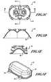
- FIGURE 1Ais a top rear perspective view of a housing formed in accordance with an embodiment of the present invention.
- FIGURE 1Bis a bottom plan view of the housing of FIGURE 1A ;
- FIGURE 1Cis a rear plan view of the housing of FIGURE 1A ;
- FIGURE 1Dis a cross-sectional view through the line 1D of FIGURE 1C ;
- FIGURE 1Eis a cross-sectional view through the line 1E of FIGURE 1C ;
- FIGURE 1Fis a perspective view of a housing cover formed in accordance with an embodiment of the present invention.
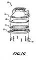
- FIGURE 1Gis an exploded view of a housing assembly formed in accordance with an embodiment of the present invention.
- FIGURE 2Ais an exploded view of an infrared (IR) light source assembly formed in accordance with an embodiment of the present invention
- FIGURES 2B and 2Care perspective views of the heat sink of the IR light source assembly of FIGURE 2A ;
- FIGURE 3Ais an exploded view of a housing and an IR diode assembly
- FIGURE 3Bis a front plan view of a lighthead assembly formed in accordance with an embodiment of the present invention.
- FIGURE 3Cis a partial exploded view of the lighthead assembly of FIGURE 3B ;
- FIGURE 4Ais a top perspective view of a lampholder assembly formed in accordance with an embodiment of the present invention.
- FIGURE 4Bis an exploded view of the lampholder assembly of FIGURE 4A ;
- FIGURE 5Ais an insulator formed in accordance with an embodiment of the present invention.
- FIGURE 5Bis an insulating bushing formed in accordance with an embodiment of the present invention.
- FIGURE 1Ashows a housing 10 including a housing rear 12 defining a plurality of lens retainer attachment points 14 located around a housing perimeter 16 ( FIG. 1G ).
- the housing rear 12also defines a searchlight slip ring shaft receptacle 18 and at least one searchlight slip ring shaft attachment point 20.
- the housing rear 12also defines a pair of lamp receptacles 22, along with a plurality of lampholder attachment points 24 and housing cover attachment points 26.
- the housing 10also defines a plurality of infrared (IR) diode assembly attachment points 28.
- the housing 10defines a reflector 30. The reflector 30 is cleaned, base coated, and then vacuum metallized.
- FIGURE 1Fshows a housing cover 31 defining a plurality of threaded receptacles 29 through which screws 108 ( FIGURE 3C ) may be inserted and attached to the housing cover attachment points 26.
- a lens retainer 32is attached to the housing 10 with a plurality of screws 34 at the lens retainer attachment points 14 ( FIG. 1A ).
- the lens retainer 32holds a gasket 36 and a lens 38 in place against the housing perimeter 16.
- FIGURE 2Ashows an IR diode assembly 40.
- the assembly 40includes an aluminum (or other suitable material) heat sink 42 defining a plurality of retainer attachment points 44.
- a retainer 46is attached to the heat sink 42 at the retainer attachment points 44 with a plurality of screws 48, and houses various components of the assembly 40.
- a circuit card assembly 50is attached to the heat sink 42 at a plurality of circuit card attachment points 52 with a plurality of screws 54.
- Wiring 56 from the circuit card assembly 50may be encased in tubing 58. The wiring 56 exits the heat sink 42 through a wiring receptacle 57 ( FIGURE 2C ).
- a plurality of thermally conductive and electrically non-conductive silicon pads 60, IR diodes 62, diode heat sinks 64, aspheric lenses 66, and diffuser retainers 68are attached to the heat sink 42 with a plurality of screws 70 at a plurality of retainer attachment points 72.
- the assembly 40includes a diode gasket 74, a light shaping diffuser 76, and a lens 78 for each diode 62; an O-ring 80 seals the components within the retainer 46, and the lenses 78 extend into lens receptacles 82 of the retainer 46.
- Aspheric lenses 66 and light shaping diffusers 76act to collimate the IR energy into a desired pattern.
- the heat sink 42defines a plurality of housing attachment points 84 through which screws 88 ( FIGURE 3A ) are inserted and attached to the IR light source assembly attachment points 28 of the housing 10 ( FIGURE 1B ).
- the wiring receptacle 57allows the wiring 56 from the circuit card assembly 50 to exit the heat sink 42.
- FIGURE 3Ashows the IR light source assembly 40 and housing 10.
- the IR light source assembly 40is attached to, and only contacts the housing 10 at, the IR light source attachment points 28 of the housing 10 with a plurality of screws 88, insulating bushings 90, and washers 92.
- a plurality of insulating bushings 90 and an insulator 96separate and reduce the amount of heat conduction between the canopy 10 and IR light source assembly 40.
- a pair of O-rings 97seal the wiring 56.
- the insulating bushings 90 and insulators 96are preferably made of polyethertherketone (PEEK) 1000, but other insulating materials known to those having ordinary skill in the art may be used.
- PEEKpolyethertherketone
- FIGURE 3Bshows a lighthead assembly 98.
- a space 99allows air flow between the IR light source assembly 40 and the housing perimeter 16, thus reducing the amount of heat convection between the housing 10 and the IR light source assembly 40; the space 99 also helps to prolong IR diode 62 life by reducing direct heat conduction between the housing 10 and the IR light source assembly 40.
- the generally circular shape of the lighthead assembly 98allows easier adaptation of the lighthead assembly 96 to conventional dual-mode lighthead envelopes (not shown).
- FIGURE 3Cshows the lighthead assembly 98.
- a pair of lampholder assemblies 100is attached to the housing 10 with a plurality of screws 104, with lamps 102 attached to the lampholder assemblies 100 protruding through the lamp receptacles 22.
- the housing cover 31 and a housing cover O-ring 106are attached to the housing 10 with a plurality of screws 108, and enclose the lampholder assemblies 100.
- FIGURES 4A and 4Bshow one lampholder assembly 100.
- the assembly 100includes screws 110 attaching a socket 112 to a lampholder 114 via selflocking nuts 116. Screws 118 secure the lampholder 114 to the housing 10 ( FIG. 1A ).
- FIGURES 5A and 5Bshow an insulator 96 and an insulating bushing 90, respectively.
- the insulator 96 and insulating bushing 90are made of polyethertherketone (PEEK) 1000, but could be made of any of a variety of different insulating materials.
- PEEKpolyethertherketone
Landscapes
- Engineering & Computer Science (AREA)
- Aviation & Aerospace Engineering (AREA)
- Arrangement Of Elements, Cooling, Sealing, Or The Like Of Lighting Devices (AREA)
Description
- Dual mode searchlights are used in rotorcraft to provide both visible lighting and infrared (IR) lighting modes, depending on the task and conditions the rotorcraft is operating under.
U.S. Patent No. 5,695,272 to Snyder et al. titled "Searchlight For Aircraft And Other Vehicles," describes an exemplary visible and infrared lighting element in a lamp head that may be extended, retracted, and rotated. Both light sources, however, are within the same lamp head (and the same lamp face), so that heat generated from the visible light source is not dissipated sufficiently to prevent degradation of the IR light source due to high temperatures generated by the heat from the visible light source.U.S. Patent No. 6,962,423 to Hamilton et al. titled "Multi-mode Searchlight," describes a multi-mode visible and infrared lighthead for use as a landing light or searchlight. The design includes a separate reflector which must be attached to the housing, and which increases maintenance costs and time. US Patent Specification 4547701 relates to an IR source of illumination for use with night vision goggles having a planar array of diodes coupled together for enhanced beam output.- Therefore, there exists a need for an improved dual-mode searchlight.
- The present invention provides a lighthhead as defined in Claim 1.
- The lighthead may include the features of any one or more of thedependent claims 2 to 8.
- Preferred embodiments of the present invention meet all of the above needs in providing a dual-mode visible and infrared (IR) searchlight assembly with an insulating barrier between the visible and IR portions of the assembly, and integral reflector.
- The two illumination sources are separated with insulation material and an air gap to improve illumination performance and meet severe operating conditions. The separation provides cooling from convective heat transfer and greatly reduces conductive heat transfer from the high power visible lighting portion of the canopy to the IR illumination portion of the canopy. The IR portion of the canopy is isolated to protect the IR sources from high temperatures.
- The reflective device for visible illumination is integrated into the housing to increase reflector area and reduce maintenance costs and time. The increase in reflector area has a direct positive effect on visible light intensity. Embodiments may include
U.S. Patent No. 6,960,776 to Machi titled "IR Diode Based High Intensity Light," which describes a high intensity, low power infrared light assembly for use on aircraft or other vehicles for landing, taxi mode, or search operations. These features contribute to reducing the size of the envelope required to harness the IR illumination sources, reducing the amount of heat generated by the searchlight, and allows the visible portion of the canopy to be larger, increasing reflector area and thus visible light intensity. - As will be readily appreciated from the foregoing summary, the invention provides an improved lighthead assembly for aircraft.
- The preferred and alternative embodiments of the present invention are described in detail below with reference to the following drawings:
FIGURE 1A is a top rear perspective view of a housing formed in accordance with an embodiment of the present invention;FIGURE 1B is a bottom plan view of the housing ofFIGURE 1A ;FIGURE 1C is a rear plan view of the housing ofFIGURE 1A ;FIGURE 1D is a cross-sectional view through the line 1D ofFIGURE 1C ;FIGURE 1E is a cross-sectional view through theline 1E ofFIGURE 1C ;FIGURE 1F is a perspective view of a housing cover formed in accordance with an embodiment of the present invention;FIGURE 1G is an exploded view of a housing assembly formed in accordance with an embodiment of the present invention;FIGURE 2A is an exploded view of an infrared (IR) light source assembly formed in accordance with an embodiment of the present invention;FIGURES 2B and 2C are perspective views of the heat sink of the IR light source assembly ofFIGURE 2A ;FIGURE 3A is an exploded view of a housing and an IR diode assembly;FIGURE 3B is a front plan view of a lighthead assembly formed in accordance with an embodiment of the present invention;FIGURE 3C is a partial exploded view of the lighthead assembly ofFIGURE 3B ;FIGURE 4A is a top perspective view of a lampholder assembly formed in accordance with an embodiment of the present invention;FIGURE 4B is an exploded view of the lampholder assembly ofFIGURE 4A ;FIGURE 5A is an insulator formed in accordance with an embodiment of the present invention; andFIGURE 5B is an insulating bushing formed in accordance with an embodiment of the present invention.FIGURE 1A shows ahousing 10 including ahousing rear 12 defining a plurality of lensretainer attachment points 14 located around a housing perimeter 16 (FIG. 1G ). Thehousing rear 12 also defines a searchlight slipring shaft receptacle 18 and at least one searchlight slip ringshaft attachment point 20. Thehousing rear 12 also defines a pair oflamp receptacles 22, along with a plurality oflampholder attachment points 24 and housingcover attachment points 26. InFIGURE 1B , thehousing 10 also defines a plurality of infrared (IR) diodeassembly attachment points 28. InFIGURES 1D and IE, thehousing 10 defines areflector 30. Thereflector 30 is cleaned, base coated, and then vacuum metallized. Thereflector 30 should have a smooth reflective appearance and show no signs of distortion. Thereflector 30 is then coated with aluminum or other suitable material known to those having skill in the art.FIGURE 1F shows ahousing cover 31 defining a plurality of threadedreceptacles 29 through which screws 108 (FIGURE 3C ) may be inserted and attached to the housingcover attachment points 26.- Referring to
FIGURE 1G , alens retainer 32 is attached to thehousing 10 with a plurality ofscrews 34 at the lens retainer attachment points 14 (FIG. 1A ). Thelens retainer 32 holds agasket 36 and alens 38 in place against thehousing perimeter 16. FIGURE 2A shows anIR diode assembly 40. Theassembly 40 includes an aluminum (or other suitable material)heat sink 42 defining a plurality ofretainer attachment points 44. Aretainer 46 is attached to theheat sink 42 at theretainer attachment points 44 with a plurality ofscrews 48, and houses various components of theassembly 40. Acircuit card assembly 50 is attached to theheat sink 42 at a plurality of circuitcard attachment points 52 with a plurality ofscrews 54. Wiring 56 from thecircuit card assembly 50 may be encased intubing 58. Thewiring 56 exits theheat sink 42 through a wiring receptacle 57 (FIGURE 2C ). A plurality of thermally conductive and electricallynon-conductive silicon pads 60,IR diodes 62,diode heat sinks 64,aspheric lenses 66, anddiffuser retainers 68 are attached to theheat sink 42 with a plurality ofscrews 70 at a plurality ofretainer attachment points 72. Theassembly 40 includes adiode gasket 74, alight shaping diffuser 76, and alens 78 for eachdiode 62; an O-ring 80 seals the components within theretainer 46, and thelenses 78 extend intolens receptacles 82 of theretainer 46.Aspheric lenses 66 andlight shaping diffusers 76 act to collimate the IR energy into a desired pattern.- In
FIGURES 2B and 2C , theheat sink 42 defines a plurality ofhousing attachment points 84 through which screws 88 (FIGURE 3A ) are inserted and attached to the IR light sourceassembly attachment points 28 of the housing 10 (FIGURE 1B ). Thewiring receptacle 57 allows thewiring 56 from thecircuit card assembly 50 to exit theheat sink 42. FIGURE 3A shows the IRlight source assembly 40 andhousing 10. The IRlight source assembly 40 is attached to, and only contacts thehousing 10 at, the IR lightsource attachment points 28 of thehousing 10 with a plurality ofscrews 88,insulating bushings 90, andwashers 92. Between thehousing 10 and the IRlight source assembly 40, a plurality of insulatingbushings 90 and aninsulator 96 separate and reduce the amount of heat conduction between thecanopy 10 and IRlight source assembly 40. A pair of O-rings 97 seal thewiring 56. The insulatingbushings 90 andinsulators 96 are preferably made of polyethertherketone (PEEK) 1000, but other insulating materials known to those having ordinary skill in the art may be used.FIGURE 3B shows alighthead assembly 98. Aspace 99 allows air flow between the IRlight source assembly 40 and thehousing perimeter 16, thus reducing the amount of heat convection between thehousing 10 and the IRlight source assembly 40; thespace 99 also helps to prolongIR diode 62 life by reducing direct heat conduction between thehousing 10 and the IRlight source assembly 40. The generally circular shape of thelighthead assembly 98 allows easier adaptation of thelighthead assembly 96 to conventional dual-mode lighthead envelopes (not shown).FIGURE 3C shows thelighthead assembly 98. A pair oflampholder assemblies 100 is attached to thehousing 10 with a plurality ofscrews 104, withlamps 102 attached to thelampholder assemblies 100 protruding through thelamp receptacles 22. Thehousing cover 31 and a housing cover O-ring 106 are attached to thehousing 10 with a plurality ofscrews 108, and enclose thelampholder assemblies 100.FIGURES 4A and 4B show onelampholder assembly 100. Theassembly 100 includesscrews 110 attaching asocket 112 to alampholder 114 via selflocking nuts 116.Screws 118 secure thelampholder 114 to the housing 10 (FIG. 1A ).FIGURES 5A and 5B show aninsulator 96 and an insulatingbushing 90, respectively. In an embodiment, theinsulator 96 and insulatingbushing 90 are made of polyethertherketone (PEEK) 1000, but could be made of any of a variety of different insulating materials.
Claims (8)
- A lighthead, comprising:a generally concave housing (10) defining a front side, a front perimeter (16),and a rear side (12), the housing (10) comprising:wherein the IR light source assembly (40) is attached to and insulated and spaced apart from the housing (10) with a plurality of screws (88), a plurality of insulating bushings (90), and at least one insulator (96).a reflector (30) located on the front side;a plurality of lens retainer attachment points (14) located around the front perimeter (16);at least one lamp receptacle (22) extending through the housing (10) and a plurality of lampholder assembly attachment points (24) located on the rear side (12) of the housing (10);at least one infrared (IR) light source assembly attachment point (28) located on the rear side (12) of the housing (10); andat least one slip ring shaft attachment point (20) located on the rear side (12) of the housing (10);an infrared (IR) light source assembly (40) attached to the at least one IR light source assembly attachment point (28) and configured to emit infrared light;a housing lens assembly attached to the front perimeter (16) of the housing (10) at the plurality of lens retainer attachment points (14),
- The lighthead of Claim 1, further comprising at least one housing cover attachment point (26) located on the rear side (12) of the housing (10).
- The lighthead of Claim 1, the IR light source assembly (40) further comprising:a heat sink (42) including at least one housing attachment point (84) and at least one retainer attachment point (44);at least one IR diode (62) configured to emit infrared light and at least one diode lens (66) covering the at least one IR diode (62); anda retainer (46) for receiving at least one diode lens (66) and for holding the at least one IR diode (62) and the at least one diode lens (66) securely in place when the retainer (46) is attached to the heat sink (42).
- The lighthead of Claim 1, the housing lens assembly (32) further comprising:a translucent lens (38) configured to allow the passage of visible light through the lens (38);a lens retainer (32) configured to hold the translucent lens (38) securely in place between the lens retainer (32) and the housing (10) when the lens retainer (32) is attached to the housing (10).
- The lighthead of Claim 1, wherein a surface of the reflector (30) is generally smooth and metallized.
- The lighthead of Claim 3, the heat sink (42) further including an outer surface, a portion of the outer surface configured such that when the IR light source assembly (40) is attached to the housing (10), air may flow in between the housing (10) and the surface of the heat sink (42).
- The lighthead of Claim 3, wherein the at least one IR diode (62) emits infrared light that is non-coherent and non-directional, and the at least one diode lens (66) is a collimating lens (66, 76) adapted to collimate infrared light to produce a beam of infrared light output from the light assembly.
- The lighthead of Claim 1, comprising:a visible light source housing (10);an infrared (IR) light source housing (40);wherein the IR light source housing (40) is attached to the visible light source housing (10) with a plurality of screws (88), insulating bushings (90), and at least one insulator (96), such that the IR light source housing (40) is spaced apart from and insulated from the visible light source housing (10).
Applications Claiming Priority (1)
| Application Number | Priority Date | Filing Date | Title |
|---|---|---|---|
| US11/554,548US7518133B2 (en) | 2006-10-30 | 2006-10-30 | Integrated searchlight lighthead |
Publications (2)
| Publication Number | Publication Date |
|---|---|
| EP1918204A1 EP1918204A1 (en) | 2008-05-07 |
| EP1918204B1true EP1918204B1 (en) | 2009-10-28 |
Family
ID=39032152
Family Applications (1)
| Application Number | Title | Priority Date | Filing Date |
|---|---|---|---|
| EP07119520AActiveEP1918204B1 (en) | 2006-10-30 | 2007-10-29 | Integrated searchlight lighthead |
Country Status (3)
| Country | Link |
|---|---|
| US (1) | US7518133B2 (en) |
| EP (1) | EP1918204B1 (en) |
| DE (1) | DE602007002967D1 (en) |
Families Citing this family (7)
| Publication number | Priority date | Publication date | Assignee | Title |
|---|---|---|---|---|
| US7850330B2 (en)* | 2008-08-20 | 2010-12-14 | Eveready Battery Co., Inc. | Lighting device configured to operate with different batteries |
| US8465178B2 (en)* | 2010-09-07 | 2013-06-18 | Cree, Inc. | LED lighting fixture |
| US8905587B1 (en) | 2011-08-09 | 2014-12-09 | The Boeing Company | Internal covert IR filter for searchlight systems |
| US8797663B1 (en) | 2011-09-15 | 2014-08-05 | The Boeing Company | Method and apparatus for selective filtering of an illumination device |
| US10180246B2 (en) | 2016-10-31 | 2019-01-15 | Honeywell International Inc. | LED searchlight and method |
| US10829244B2 (en)* | 2018-02-08 | 2020-11-10 | Honeywell International Inc. | LED lighting devices with high extraction efficiencies |
| US11192494B2 (en) | 2020-02-07 | 2021-12-07 | Honeywell International Inc. | Systems and methods for search and landing light |
Family Cites Families (9)
| Publication number | Priority date | Publication date | Assignee | Title |
|---|---|---|---|---|
| US4547701A (en) | 1983-07-01 | 1985-10-15 | Bell Helicopter Textron Inc. | IR Light for use with night vision goggles |
| US5695272A (en)* | 1994-05-27 | 1997-12-09 | Grimes Aerospace Company | Search light for aircraft and other vehicles |
| WO2000037314A1 (en)* | 1998-12-21 | 2000-06-29 | Alliedsignal Inc. | Ir diode based high intensity light |
| US6315435B1 (en)* | 1999-02-18 | 2001-11-13 | Alliedsignal Inc. | Electronically controlled searchlight having multiple preset positions |
| GB9911943D0 (en) | 1999-05-21 | 1999-07-21 | Avimo Ltd | Improvements in lighting |
| US6609812B2 (en)* | 2000-12-20 | 2003-08-26 | Honeywell International Inc. | Dual mode visible and infrared lighthead |
| US20040113817A1 (en)* | 2001-08-07 | 2004-06-17 | Novak Harvey M. | Flashing infrared beacon system |
| US6962423B2 (en)* | 2001-11-06 | 2005-11-08 | Honeywell International Inc. | Multi-mode searchlight |
| EP1683720B1 (en) | 2001-11-06 | 2008-08-13 | Honeywell International Inc. | Multi-mode searchlight |
- 2006
- 2006-10-30USUS11/554,548patent/US7518133B2/enactiveActive
- 2007
- 2007-10-29EPEP07119520Apatent/EP1918204B1/enactiveActive
- 2007-10-29DEDE602007002967Tpatent/DE602007002967D1/enactiveActive
Also Published As
| Publication number | Publication date |
|---|---|
| US20080142742A1 (en) | 2008-06-19 |
| EP1918204A1 (en) | 2008-05-07 |
| US7518133B2 (en) | 2009-04-14 |
| DE602007002967D1 (en) | 2009-12-10 |
Similar Documents
| Publication | Publication Date | Title |
|---|---|---|
| CA3102022C (en) | Lighting module for recessed lighting systems | |
| EP1918204B1 (en) | Integrated searchlight lighthead | |
| EP2191195B1 (en) | Compact omnidirectional led light | |
| EP2646743B1 (en) | Lighting fixture | |
| US9234655B2 (en) | Lamp with remote LED light source and heat dissipating elements | |
| US8201985B2 (en) | Light bulb utilizing a replaceable LED light source | |
| CN1721762B (en) | Light assembly | |
| US20120320591A1 (en) | Light bulb | |
| US20140001956A1 (en) | Lighting Device | |
| US9644830B2 (en) | Application-specific LED module and associated LED point source luminaires | |
| CN109983272B (en) | Lighting module, luminaire comprising a lighting module and method of mounting a lighting module in a luminaire | |
| US20070090386A1 (en) | Air cooled high-efficiency light emitting diode spotlight or floodlight | |
| US20240255123A1 (en) | Led lamp | |
| US9279548B1 (en) | Light collimating assembly with dual horns | |
| JP2021192378A (en) | lamp | |
| EP3228930B1 (en) | Heat dissipating reflectors for led luminaires | |
| EP3403937B1 (en) | Exterior aircraft light unit | |
| EP2856023B1 (en) | Lighting device having a light source heat sink arranged separate from a driver | |
| EP2573450B1 (en) | Airport and heliport lighting system | |
| US20240401757A1 (en) | Led lamp | |
| WO2018134906A1 (en) | Lamp | |
| GB2600149A (en) | A replaceable LED unit for luminaires and integrated lamp luminaires | |
| US20130329428A1 (en) | Light emitting diode (led) assembly | |
| GB2550128A (en) | Lighting unit | |
| KR20180034171A (en) | Lamp unit and lighting device |
Legal Events
| Date | Code | Title | Description |
|---|---|---|---|
| PUAI | Public reference made under article 153(3) epc to a published international application that has entered the european phase | Free format text:ORIGINAL CODE: 0009012 | |
| 17P | Request for examination filed | Effective date:20071029 | |
| AK | Designated contracting states | Kind code of ref document:A1 Designated state(s):AT BE BG CH CY CZ DE DK EE ES FI FR GB GR HU IE IS IT LI LT LU LV MC MT NL PL PT RO SE SI SK TR | |
| AX | Request for extension of the european patent | Extension state:AL BA HR MK RS | |
| 17Q | First examination report despatched | Effective date:20080617 | |
| AKX | Designation fees paid | Designated state(s):DE FR | |
| GRAP | Despatch of communication of intention to grant a patent | Free format text:ORIGINAL CODE: EPIDOSNIGR1 | |
| GRAS | Grant fee paid | Free format text:ORIGINAL CODE: EPIDOSNIGR3 | |
| GRAA | (expected) grant | Free format text:ORIGINAL CODE: 0009210 | |
| AK | Designated contracting states | Kind code of ref document:B1 Designated state(s):DE FR | |
| REF | Corresponds to: | Ref document number:602007002967 Country of ref document:DE Date of ref document:20091210 Kind code of ref document:P | |
| PGFP | Annual fee paid to national office [announced via postgrant information from national office to epo] | Ref country code:FR Payment date:20091120 Year of fee payment:3 | |
| PLBE | No opposition filed within time limit | Free format text:ORIGINAL CODE: 0009261 | |
| STAA | Information on the status of an ep patent application or granted ep patent | Free format text:STATUS: NO OPPOSITION FILED WITHIN TIME LIMIT | |
| 26N | No opposition filed | Effective date:20100729 | |
| PG25 | Lapsed in a contracting state [announced via postgrant information from national office to epo] | Ref country code:FR Free format text:LAPSE BECAUSE OF NON-PAYMENT OF DUE FEES Effective date:20101102 | |
| REG | Reference to a national code | Ref country code:FR Ref legal event code:ST Effective date:20110630 | |
| P01 | Opt-out of the competence of the unified patent court (upc) registered | Effective date:20230525 | |
| PGFP | Annual fee paid to national office [announced via postgrant information from national office to epo] | Ref country code:DE Payment date:20241029 Year of fee payment:18 |