EP1918156A1 - Support assembly for a seat - Google Patents
Support assembly for a seatDownload PDFInfo
- Publication number
- EP1918156A1 EP1918156A1EP06023098AEP06023098AEP1918156A1EP 1918156 A1EP1918156 A1EP 1918156A1EP 06023098 AEP06023098 AEP 06023098AEP 06023098 AEP06023098 AEP 06023098AEP 1918156 A1EP1918156 A1EP 1918156A1
- Authority
- EP
- European Patent Office
- Prior art keywords
- bowden cable
- support assembly
- support
- assembly according
- cable wire
- Prior art date
- Legal status (The legal status is an assumption and is not a legal conclusion. Google has not performed a legal analysis and makes no representation as to the accuracy of the status listed.)
- Granted
Links
- 230000008878couplingEffects0.000claimsabstractdescription68
- 238000010168coupling processMethods0.000claimsabstractdescription68
- 238000005859coupling reactionMethods0.000claimsabstractdescription68
- 230000008859changeEffects0.000claimsabstractdescription3
- 210000002445nippleAnatomy0.000claimsdescription10
- 230000000694effectsEffects0.000claimsdescription5
- 238000010276constructionMethods0.000description7
- 230000000712assemblyEffects0.000description6
- 238000000429assemblyMethods0.000description6
- 230000009471actionEffects0.000description3
- 238000004873anchoringMethods0.000description3
- 230000007246mechanismEffects0.000description3
- 239000000463materialSubstances0.000description2
- 229910000831SteelInorganic materials0.000description1
- 230000003247decreasing effectEffects0.000description1
- 230000001419dependent effectEffects0.000description1
- 210000004705lumbosacral regionAnatomy0.000description1
- 239000002184metalSubstances0.000description1
- 230000004048modificationEffects0.000description1
- 238000012986modificationMethods0.000description1
- 239000010959steelSubstances0.000description1
- 239000000725suspensionSubstances0.000description1
- 230000007704transitionEffects0.000description1
Images


Classifications
- B—PERFORMING OPERATIONS; TRANSPORTING
- B60—VEHICLES IN GENERAL
- B60N—SEATS SPECIALLY ADAPTED FOR VEHICLES; VEHICLE PASSENGER ACCOMMODATION NOT OTHERWISE PROVIDED FOR
- B60N2/00—Seats specially adapted for vehicles; Arrangement or mounting of seats in vehicles
- B60N2/64—Back-rests or cushions
- B60N2/66—Lumbar supports
- B60N2/667—Lumbar supports having flexible support member bowed by applied forces
- B60N2/6671—Lumbar supports having flexible support member bowed by applied forces with cable actuators
- A—HUMAN NECESSITIES
- A47—FURNITURE; DOMESTIC ARTICLES OR APPLIANCES; COFFEE MILLS; SPICE MILLS; SUCTION CLEANERS IN GENERAL
- A47C—CHAIRS; SOFAS; BEDS
- A47C7/00—Parts, details, or accessories of chairs or stools
- A47C7/36—Supports for the head or the back
- A47C7/40—Supports for the head or the back for the back
- A47C7/46—Supports for the head or the back for the back with special, e.g. adjustable, lumbar region support profile; "Ackerblom" profile chairs
- A47C7/462—Supports for the head or the back for the back with special, e.g. adjustable, lumbar region support profile; "Ackerblom" profile chairs adjustable by mechanical means
- A47C7/465—Supports for the head or the back for the back with special, e.g. adjustable, lumbar region support profile; "Ackerblom" profile chairs adjustable by mechanical means by pulling an elastic cable
Definitions
- the present inventionrelates to a support assembly for a seat.
- an adjustable support assemblysuch as a lumbar support assembly, that includes a support device, such as a wire framework, overmolded wires, or an overmolded wire pad, which support assembly is adjustable and provides load bearing support for upholstery of a seat, for example for use in automotive or furniture seating.
- Support assemblies of the aforementioned kindare well-known in the art and may have various configurations determined by the design of the seat in which the support assembly is to be mounted.
- a support assembly of this kindis for example known from GB 2 342 287 A .
- the support assembly described in this documentcomprises a wire framework having two lateral side wires which are suspendable in a seat frame and between which there extends a plurality of transverse wires for providing load bearing support for upholstery of the seat.
- EP 0 552 904 B1to provide an adjusting mechanism for a support assembly.
- the support assembly disclosed in this documentis attached to a seat frame via springs, and Bowden cable mechanisms are provided by means of which the support assembly can be pivoted at hinge points provided on the lateral side wires.
- a further mechanism that does not require the use of such hingesis known from US 5,988,745 A .
- the support device or a part thereofis usually moved in a direction extending perpendicular to a support plane.
- the support devicemay be pivoted about a transversal axis, may be arched or may be moved as a whole.
- it is desirable that the support deviceis moved on both of its lateral sides in an identical manner so that a symmetric lumbar support feeling is created.
- Such a symmetrical movement of both sides of the support deviceis, however, difficult to achieve and typically requires two separate Bowden cable arrangements which render the design of the support assembly more complicated and more costly.
- EP 1 680 984 A1A solution to this problem has been proposed in EP 1 680 984 A1 .
- the solutionconsists in a sheath of a single Bowden cable arrangement being attached to first and second side members of a support arrangement via first and second attachment means, respectively.
- the use of a single Bowden cable to provide adjustable lumbar support by simultaneously acting on two side members of the support arrangementhas the effect that symmetrical support may be provided while keeping the construction of the support assembly simple.
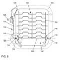
- Fig. 6shows a lumbar support assembly as disclosed in EP 1 680 984 A1 .
- the support assembly 102comprises a wire framework 103 that is attached to a seat frame 101 via suitable means, such as hooks.
- the wire framework 103comprises two side wires 104.
- a Bowden cable 110comprises a sheath 111 and a wire extending therethrough, which is at one end coupled to an actuator 120. Another end of the Bowden cable wire is formed in the shape of a hook 113 for engagement with the seat frame 101.
- the Bowden cable sheath 111is attached to both lateral side wires 104 via attachment brackets 117 and 115, respectively, which include through holes 118 and 116, respectively, for the Bowden cable wire.
- the attachment bracket 117is attached to the seat frame 101 via a spring 119.
- a free length of the Bowden cable wireis changed via actuator 120, which has the effect of a force acting symmetrically on the two lateral side wires 104 of the wire framework 103.
- a problem of the support assembly shown in Fig. 6is that the Bowden cable 111 has to make a very sharp bend in proximity to the position of the spring 119. More specifically, as may be seen in the detail view of Fig. 7, which shows the region indicated by a dashed circle VII in Fig. 6, the Bowden cable sheath 111 is guided along the seat frame 101 before entering spring 119. The guiding may be achieved, e.g., in that a portion 122 of the Bowden cable sheath 111 is clampingly held in a guiding groove 121.
- the region in which the Bowden cable sheath 111 may be attached to the seat frame 101is also limited, which results in the Bowden cable sheath 111 having a sharp bend in the region where it leaves the guiding groove 121 and enters spring 119, i.e., the curvature radius R is small.
- the sharp bendmay give rise to several problems, such as a reduced durability of the Bowden cable 110, unstable cable routing or noise when the support assembly is re-adjusted.
- a support assembly for a seatwhich comprises a support device that is configured to be attached to a seat frame and has a first side and a second side, the support device being adjustable by acting on the first side and the second side.
- the support assemblyfurther comprises a Bowden cable arrangement having a Bowden cable wire and a Bowden cable sheath.
- a traction deviceis coupled to both the first side and the second side of the support device for acting thereon.
- the support assemblyfurther comprises a coupling device which couples the traction device and the Bowden cable arrangement in such a manner that the traction device is acted on in dependence on a tension of the Bowden cable wire. It is to be appreciated that, typically, the traction device will be distinct and separate from the Bowden cable arrangement.
- the first side and the second side of the support devicemay, in particular, be lateral sides of the support device, i.e., longitudinally extending sides.
- the coupling deviceacts on the traction device in such a way that a tension of the traction device is changed in dependence on a tension of the Bowden cable wire.
- the tension of the Bowden cable wireis, in turn, preferably adjusted by adjusting a free length or extension length of the Bowden cable wire using an actuator.
- a change of the tension of the traction device in dependence on the tension of the Bowden cable wireis preferably achieved in that an end portion of the Bowden cable sheath is attached to the coupling device, an end portion of the Bowden cable wire extends from the coupling device in an extension direction, and the traction device extends from the coupling device in a direction that is essentially opposite to the extension direction.
- the end portion of the Bowden cable wire that extends from the coupling deviceis preferably configured to be attached to the seat frame.
- the traction deviceis a further Bowden cable arrangement having a further Bowden cable wire and a further Bowden cable sheath.
- the support assemblymay then comprise attachment means for attaching an end portion of the further Bowden cable wire to the coupling device.
- the attachment meansmay, for example, comprise an attachment hole formed in a body of the coupling device that comprises a narrow portion for receiving the Bowden cable wire and a nipple formed at the end portion having outer dimensions larger than a diameter of the narrow portion.
- the further Bowden cable arrangementis securely anchored to the coupling device.
- the further Bowden cable arrangementis a particularly advantageous implementation of the traction device as it can be handled easily and as it allows, by virtue of its flexibility, that the first side and the second side of the support device may be acted on in a symmetric manner.
- another end portion of the further Bowden cable wire which is not attached to the coupling deviceis configured to be connected to a side of the seat frame, and an end portion of the Bowden cable wire extending from the coupling device is configured to be connected to another side of the seat frame.
- the support assemblymay be attached to the seat frame in such a manner that the further Bowden cable wire extends from the side of the seat frame to the coupling device, and that the Bowden cable wire extends from the coupling device to the other side of the seat frame, thereby bridging the full distance between the sides of the seat frame and allowing the support assembly to be hooked onto the seat frame.
- the end portions of the further Bowden cable wire and/or of the Bowden cable wiremay have a shape for hooking engagement with the seat frame, e.g., in the form of a Z-shaped nipple.
- the further Bowden cable sheathextends continuously from the first side to the second side of the support device.
- the continuously extending further Bowden cable sheathprevents a feeling of discomfort when the further Bowden cable wire is tensioned and the support device is moved or arched.
- holding meansare provided for slidably holding the further Bowden cable wire with respect to the support device.
- the holding meansmay have a clip portion for attaching the holding means to the support device.
- the holding meansmay further have guiding means for guiding a portion of the further Bowden cable wire.
- the holding meanspreferably have retaining means for retaining an end of the further Bowden cable sheath, thereby allowing the end of the further Bowden cable sheath to be attached to the first side and/or the second side of the support device via the holding means.
- the clip portionallows the holding means to be clipped or snapped onto the support device.
- the subassembly comprised of the Bowden cable, the further Bowden cable arrangement, and the coupling devicemay be formed separately from the support device and may be snapped onto the support device at a convenient stage of assembly.
- the support assemblymay also include not only one traction device, but rather a plurality of traction devices coupled to the first and second sides of the support device for acting thereon at positions offset from each other, as well as respective Bowden cable arrangements and respective coupling devices for coupling the respective traction devices and the respective Bowden cable arrangements.
- the support devicemay have any suitable configuration.
- the support devicemay comprise a first and second side member forming the first and second side of the support device, respectively.
- a plurality of transverse membersmay extends between the first and second side members.
- the support devicemay, e.g., comprise a wire framework, overmolded wires, an overmolded wire pad or any other suitable adjustable support device.
- a seat structurewhich comprises a seat frame and the support assembly according to any one embodiment of the invention.
- the coupling deviceis employed for coupling the traction device and the Bowden cable arrangement.
- the Bowden cablewhich is at one end coupled to an actuator does no longer need to be strongly bent.
- a symmetric support feelingis maintained by symmetric action of the traction device onto the first side and the second side of the support device.
- the support assembly according to the various aspects and embodiments of the present inventionmay be employed to any kind of seats.
- the present inventionmay be applied to seats in which high seating comfort, adjustability and durability is desired, such as automotive or furniture seating.
- Fig. 1is a schematic plan view from back of a support assembly according to an embodiment of the invention.
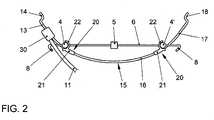
- Fig. 2is a schematic top view of the support assembly of Fig. 1.
- Fig. 3is a perspective detail view of the support assembly of Fig. 1.
- Fig. 4Ais a schematic top view of a coupling device employed in the support assembly of Fig. 1, and Fig. 4B is a schematic cross sectional view.
- Fig. 5is a schematic plan view from back of a support assembly according to another embodiment of the invention.
- Fig. 6is a plan view of a conventional support assembly.
- Fig. 7is a detail view of the support assembly of Fig. 6.
- Fig. 1shows a support assembly 2 for a seat according to an embodiment of the invention which is to be attached to a seat frame 1 schematically indicated by broken lines.
- the support assembly 2comprises a support device 3 which is also referred to as a suspension pad or a platform element in the art.
- the support device 3is formed as a wire framework.
- the support device 3comprises a first side wire 4 and a second side wire 4' forming elongate side members and a plurality of transverse wires 6 extending between the side wires 4, 4'.
- the transverse wires 6are anchored to the side wires 4, 4', e.g., by being wound around the side wires 4, 4'.
- transverse wires 6are angled in the support plane so that the support device 3 becomes extensible under loading placed on the support device.
- the transverse wires 6penetrate through or are coupled to an intermediate vertical cord 5, which may be formed of paper or synthetic plastic material and which serves to provide some additional stability to the wire framework. Further, the intermediate vertical cord 5 assists in maintaining a predetermined vertical spacing between the transverse wires 6.
- the side wires 4, 4'may be formed for example of paper wrapped steel cords.
- one or several of the transverse wires 6may laterally extend beyond the side wires 4, 4' so as to terminate in free ends 8. These free ends 8 may be formed into hook-like fingers for hooking engagement with the seat frame 1, so as to attach the support assembly to the seat frame. While not shown in Fig. 1, other transverse wires 6 may also laterally extend beyond the side wires 4, 4' so as to terminate in free ends which are suitably shaped in order to enable more versatile lateral support to be provided, particularly in the lumbar region of a backrest. Further, while not shown in Fig. 1, the support device 3 may also be attached to the seat frame 1 at lower ends of the side wires 4, 4'.
- the implementation of the support device 3 in the form of a wire frameworkis only exemplary and may be substituted by any other suitable device that provides support for upholstery of a seat.
- the support device 3may also be constituted by a partially or fully overmolded wire pad, or an integrally formed support device made of plastic or metal that provides sufficient support and adjustability.
- the side wires 4, 4'may be substituted by other suitable side members, such as push rods.
- the support device 3is adjustable since a lower portion of the side wires 4, 4' may be moved in a forward and backward direction, resulting in a pivoting motion of the support device, possibly accompanied by an arching of the side wires 4, 4'.
- the support assembly 2comprises an adjustment assembly that generally includes a Bowden cable 10, a further Bowden cable 15, a coupling device 30 and an actuator 40.
- the Bowden cable 10has a Bowden cable sheath 11 and a Bowden cable wire 12, only an end portion 13 of which is shown in Fig. 1.
- the Bowden cable wireextends through the coupling device 30 and has its ends anchored to a pulley 41 of the actuator 40 and a side of the seat frame 1, respectively.
- a hook portion 14is provided on the end portion 13 of the Bowden cable wire, which hook portion 14 may, for example, have the form of a Z-shaped nipple.
- the further Bowden cable 15is coupled both to the first side wire 4 and to the second side wire 4' of the support device 3 for acting thereon. Therefore, in the embodiment of Fig. 1, the further Bowden cable 15 corresponds to the traction device as recited herein.
- the further Bowden cable 15comprises a further Bowden cable sheath 16 and a further Bowden cable wire 17.
- the further Bowden cable wire 17has its ends anchored on the coupling device 30 and the seat frame 1, respectively.
- an end portion of the further Bowden cable wire 17is provided with a hook portion 18 which, again, may have the form of a Z-shaped nipple.
- Holding means 20are attached to the first side wire 4 and the second side wire 4' and slidingly hold the further Bowden cable wire 17 with respect to the support device 3.
- the pair of holding means 20has the function of attaching the further Bowden cable sheath 16 to the side wires 4, 4'.
- the holding means 20each comprise a clip portion 22 for attaching the holding means to the respective side wires 4, 4' and guiding means 21 for guiding a portion of the further Bowden cable wire 17.
- the clip portion 22has elasticity and has an internal shape and internal dimensions so as to conform with the side wires 4 or 4', respectively.
- the holding means 20may be readily clipped or snapped onto the side wires 4, 4'.
- the guiding means 21is arcuately-shaped in order to assist the further Bowden cable 15 to be in the configuration arched relative to the support plane of the support device 3, as shown in the top view of Fig. 2.
- the retaining means 21have a hole for receiving and retaining ends of the further Bowden cable sheath 16, which hole has an inner diameter slightly larger than an outer diameter of the Bowden cable sheath 16 and comprises a shoulder for abutment of the end of the Bowden cable sheath 16.
- Fig. 4Ais a plan view of the coupling device 30 and the Bowden cable and further Bowden cable components attached thereto
- Fig. 4Brepresents a cross-sectional view.
- a body 31 of the coupling device 30has two holes 32, 35 formed therein.
- the guiding hole 32functions as a guiding means for guiding the Bowden cable wire 12 through the coupling device 30 along an essentially straight path.
- the guiding hole 32has a large-diameter portion 33 and a small-diameter portion 34.
- the large-diameter portion 33has a diameter slightly larger than an outer diameter of the Bowden cable sheath 11.
- the small-diameter portion 34has a diameter essentially equal to or slightly larger than an outer diameter of the further Bowden cable wire 12. While the Bowden cable wire 12 extends through both the large-diameter portion 33 and the small-diameter portion 34, an end portion of the Bowden cable sheath 11 is received in the large-diameter portion 33 and abuts on a shoulder formed at the transition from the large-diameter portion 33 to the small-diameter portion 34, thereby anchoring or attaching the Bowden cable sheath 11 to the coupling device 30.
- attachment hole 35in combination with a nipple 39 provided on an end portion of the further Bowden cable wire 17 functions as attachment means for attaching or anchoring the further Bowden cable wire 17 on the coupling device 30.
- the attachment hole 35also comprises a large-diameter portion 38 and a small-diameter portion 36.
- the small-diameter portion 36has a diameter essentially equal to or slightly larger than an outer diameter of the further Bowden cable wire 17.
- the nipple 39is received in the large-diameter portion 38, but has outer dimensions larger than the diameter of the small-diameter portion 36 which prevents the nipple 39 from being drawn into the small-diameter portion 36 as the further Bowden cable wire 17 becomes tensioned.
- the coupling device 30is constructed in such a way that the free end 13 of the Bowden cable wire 12 that is to be hinged onto the seat frame and the further Bowden cable wire 17 extend from the coupling device 30 in essentially opposite directions, namely to the left and to the right in Fig. 4b. Further, both the Bowden cable wire 12 and the further Bowden cable wire 17 are guided through the body 31 of the coupling device 30 along an essentially straight path. It should be noted that, while the holes in Fig. 4b are shown to be essentially straight, the holes could also be slightly bent, as long as the radius of curvature of the holes does not become too small. This construction of the coupling device 30 as shown in Fig. 4b has several important effects.
- the coupling device 30allows tension applied to the Bowden cable wire 12 via actuator 40 to be transferred onto the further Bowden cable wire 17.
- the coupling device 30is simple in construction and may therefore be manufactured at low costs.
- the body 31 of the coupling device 30may be made of any suitable material that has sufficient rigidity and durability to withstand the loads applied to the Bowden cable 10 and the further Bowden cable wires 17.
- the body 31 of the coupling device 30may be made, e.g., of plastic.
- the support device 3is adjustable by acting on the first side wire 4 and the second side wire 4', the action of the further Bowden cable wire 17 in turn results in the support device 3 being adjusted.
- the hooks or Z-shaped nipples 14, 18are hooked into the seat frame at positions forward of the support device 3, the of tensioning the further Bowden cable wire 17 will more specifically result in the lower portion of the support device 3 being pushed forward, resulting in an arching, possibly in combination with a pivoting of the support device.
- Figs. 1-4only comprises one adjustment assembly for adjusting the lower portion of the support device 3, the present invention is not limited thereto. Rather, a plurality of adjustment assemblies may be provided to a support device, so as to adjust several portions of the support device.
- Fig. 5shows another embodiment of the invention in which two adjustment assemblies are applied to the support device 3.
- Identical or similar componentsare labelled identically or similarly to the embodiment of Fig. 1.
- a first adjustment assemblycomprises a Bowden cable 10a and a further Bowden cable 15a coupled to the Bowden cable 10a via a coupling device 30a and attached to the side wires 4, 4' via holding means 20a.
- the construction and arrangement of these componentsis identical to the one of the corresponding components explained with reference to Fig. 1 above.
- a second adjustment assemblycomprises also a Bowden cable 10b and a further Bowden cable 15b coupled to the Bowden cable 10b via a coupling device 30b and attached to the side wires 4, 4' via holding means 20b.
- the further Bowden cable 15b of the second adjustment meansis coupled to the side wires 4, 4' at positions that are vertically offset from the positions at which the further Bowden cable 15a of the first adjustment assembly is coupled to the side wires.
- the Bowden cable wire of the Bowden cable 10a or the Bowden cable wire of the Bowden cable 10bis tensioned, different portions of the support device 3 are acted on and a person sitting on the seat will perceive different support feelings.
- the ends of the Bowden cable wire of the Bowden cable 10b and of the Bowden cable wire of the Bowden cable 10aare both attached to the same pulley 41 in such a manner that, when one wire is wound onto the pulley, the other wire is played out. Consequently, a rotation of the pulley 41 in a first direction will result in a support region or a support point moving downward, while a rotation of the pulley 41 in a second, opposite direction will result in the support region or support point moving upward.
- the actuator 40may be a powered actuator that is controlled by a control unit in such a way that the pulley 41 is sequentially rotated through a series of rotary positions.
- the support portion or support point perceived by the person sitting on the seatmay move upward and downward such that it generates a massage effect.
- the support device in the above embodimentsis a wire framework
- any other suitable support device that provides sufficient support for upholstery of the seat and is adjustable by acting on both sides thereofmay be employed with equal facility.
- a pad of overmolded wiresmay be substituted for the wire framework in the above embodiments.
- the support devicedoes not necessarily need to have separate side members, as long as it is adjustable by acting on both sides thereof.
- the end portions of the Bowden cable wire and of the further Bowden cable wire, such as the hook portions 14 and 18,do not have to be directly coupled to the seat frame 1.
- springsmay be provided between the seat frame and the hook portions 14 and 18, i.e., the end portions of the Bowden cable wire and of the further Bowden cable wire may be coupled to the seat frame via springs.
- the coupling device 30is not limited to the configuration shown in Fig. 4. Rather, any coupling device that suitably couples the Bowden cable to the further Bowden cable may be employed.
- the further Bowden cablemay be substituted by any suitable traction device that provides a symmetric action on both sides of the support device.
- the lumbar support assemblies according to the various embodiments of the inventionprovide a symmetrical support feeling to the person sitting on the seat, since one traction device is used for acting on both sides of the support device. Further, sharp bends on the Bowden cable are eliminated due to the coupling of the Bowden cable to the traction device.
- the coupling device 30has a simple configuration, which makes the support assembly simple in construction and cost-efficient.
Landscapes
- Engineering & Computer Science (AREA)
- Mechanical Engineering (AREA)
- Aviation & Aerospace Engineering (AREA)
- Transportation (AREA)
- Seats For Vehicles (AREA)
Abstract
Description
- The present invention relates to a support assembly for a seat. In particular, the present invention relates to an adjustable support assembly, such as a lumbar support assembly, that includes a support device, such as a wire framework, overmolded wires, or an overmolded wire pad, which support assembly is adjustable and provides load bearing support for upholstery of a seat, for example for use in automotive or furniture seating.
- Support assemblies of the aforementioned kind are well-known in the art and may have various configurations determined by the design of the seat in which the support assembly is to be mounted. A support assembly of this kind is for example known from
GB 2 342 287 A - Furthermore, it is known from
EP 0 552 904 B1 to provide an adjusting mechanism for a support assembly. The support assembly disclosed in this document is attached to a seat frame via springs, and Bowden cable mechanisms are provided by means of which the support assembly can be pivoted at hinge points provided on the lateral side wires. A further mechanism that does not require the use of such hinges is known fromUS 5,988,745 A . - In order to adjust the degree of lumbar support, the support device or a part thereof is usually moved in a direction extending perpendicular to a support plane. In order to achieve the adjustment, the support device may be pivoted about a transversal axis, may be arched or may be moved as a whole. In each case, it is desirable that the support device is moved on both of its lateral sides in an identical manner so that a symmetric lumbar support feeling is created. Such a symmetrical movement of both sides of the support device is, however, difficult to achieve and typically requires two separate Bowden cable arrangements which render the design of the support assembly more complicated and more costly.
- A solution to this problem has been proposed in
EP 1 680 984 A1 - Fig. 6 shows a lumbar support assembly as disclosed in
EP 1 680 984 A1support assembly 102 comprises awire framework 103 that is attached to aseat frame 101 via suitable means, such as hooks. Thewire framework 103 comprises twoside wires 104. A Bowdencable 110 comprises asheath 111 and a wire extending therethrough, which is at one end coupled to anactuator 120. Another end of the Bowden cable wire is formed in the shape of ahook 113 for engagement with theseat frame 101. The Bowdencable sheath 111 is attached to bothlateral side wires 104 viaattachment brackets holes attachment bracket 117 is attached to theseat frame 101 via aspring 119. In order to adjust thesupport assembly 102, a free length of the Bowden cable wire is changed viaactuator 120, which has the effect of a force acting symmetrically on the twolateral side wires 104 of thewire framework 103. - A problem of the support assembly shown in Fig. 6 is that the Bowden
cable 111 has to make a very sharp bend in proximity to the position of thespring 119. More specifically, as may be seen in the detail view of Fig. 7, which shows the region indicated by a dashed circle VII in Fig. 6, the Bowdencable sheath 111 is guided along theseat frame 101 before enteringspring 119. The guiding may be achieved, e.g., in that aportion 122 of the Bowdencable sheath 111 is clampingly held in a guidinggroove 121. With the size of theseat frame 101 being limited, the region in which the Bowdencable sheath 111 may be attached to theseat frame 101 is also limited, which results in the Bowdencable sheath 111 having a sharp bend in the region where it leaves theguiding groove 121 and entersspring 119, i.e., the curvature radius R is small. - The sharp bend may give rise to several problems, such as a reduced durability of the Bowden
cable 110, unstable cable routing or noise when the support assembly is re-adjusted. - It is an object of the present invention to provide an improved support assembly for a seat. In particular, it is an object to provide a support assembly having a simple structure and avoiding sharp bends in the Bowden cable. It is yet another object of the present invention to provide such a support assembly that avoids problems related to unstable cable routing.
- According to the present invention, this object is achieved by a support assembly as defined in
claim 1. The dependent claims define preferred or advantageous embodiments of the invention. - According to an aspect of the invention, a support assembly for a seat is provided which comprises a support device that is configured to be attached to a seat frame and has a first side and a second side, the support device being adjustable by acting on the first side and the second side. The support assembly further comprises a Bowden cable arrangement having a Bowden cable wire and a Bowden cable sheath. A traction device is coupled to both the first side and the second side of the support device for acting thereon. The support assembly further comprises a coupling device which couples the traction device and the Bowden cable arrangement in such a manner that the traction device is acted on in dependence on a tension of the Bowden cable wire. It is to be appreciated that, typically, the traction device will be distinct and separate from the Bowden cable arrangement. Since the traction device is coupled to both the first side and the second side of the support device, a symmetrical support feeling may be achieved when the traction device is tensioned or untensioned and simultaneously acts on the two sides. Since a tension applied to the Bowden cable wire may be transferred to the traction device via the coupling device, it is no longer necessary for the Bowden cable arrangement to be attached to both sides of the support device. Rather, the provision of the traction device that is separate from and coupled to the Bowden cable arrangement affords additional design options that allow sharp bends of the Bowden cable to be reduced or eliminated. The first side and the second side of the support device may, in particular, be lateral sides of the support device, i.e., longitudinally extending sides.
- Preferably, the coupling device acts on the traction device in such a way that a tension of the traction device is changed in dependence on a tension of the Bowden cable wire. The tension of the Bowden cable wire is, in turn, preferably adjusted by adjusting a free length or extension length of the Bowden cable wire using an actuator.
- A change of the tension of the traction device in dependence on the tension of the Bowden cable wire is preferably achieved in that an end portion of the Bowden cable sheath is attached to the coupling device, an end portion of the Bowden cable wire extends from the coupling device in an extension direction, and the traction device extends from the coupling device in a direction that is essentially opposite to the extension direction. The end portion of the Bowden cable wire that extends from the coupling device is preferably configured to be attached to the seat frame. By virtue of this construction, sharp bends of the Bowden cable may be avoided, since the Bowden cable wire may smoothly extend throughout the coupling device towards the seat frame. When the free length of the Bowden cable wire is changed, the coupling device is moved towards or away from the seat frame, thereby adjusting the tension of the traction device in dependence on the tension applied to the Bowden cable wire.
- Preferably, the traction device is a further Bowden cable arrangement having a further Bowden cable wire and a further Bowden cable sheath. The support assembly may then comprise attachment means for attaching an end portion of the further Bowden cable wire to the coupling device. The attachment means may, for example, comprise an attachment hole formed in a body of the coupling device that comprises a narrow portion for receiving the Bowden cable wire and a nipple formed at the end portion having outer dimensions larger than a diameter of the narrow portion. Thereby, the further Bowden cable arrangement is securely anchored to the coupling device. The further Bowden cable arrangement is a particularly advantageous implementation of the traction device as it can be handled easily and as it allows, by virtue of its flexibility, that the first side and the second side of the support device may be acted on in a symmetric manner.
- Preferably, another end portion of the further Bowden cable wire which is not attached to the coupling device is configured to be connected to a side of the seat frame, and an end portion of the Bowden cable wire extending from the coupling device is configured to be connected to another side of the seat frame. Thereby, the support assembly may be attached to the seat frame in such a manner that the further Bowden cable wire extends from the side of the seat frame to the coupling device, and that the Bowden cable wire extends from the coupling device to the other side of the seat frame, thereby bridging the full distance between the sides of the seat frame and allowing the support assembly to be hooked onto the seat frame. The end portions of the further Bowden cable wire and/or of the Bowden cable wire may have a shape for hooking engagement with the seat frame, e.g., in the form of a Z-shaped nipple.
- In a preferred embodiment, the further Bowden cable sheath extends continuously from the first side to the second side of the support device. The continuously extending further Bowden cable sheath prevents a feeling of discomfort when the further Bowden cable wire is tensioned and the support device is moved or arched.
- Preferably, holding means are provided for slidably holding the further Bowden cable wire with respect to the support device. The holding means may have a clip portion for attaching the holding means to the support device. The holding means may further have guiding means for guiding a portion of the further Bowden cable wire. Still further, the holding means preferably have retaining means for retaining an end of the further Bowden cable sheath, thereby allowing the end of the further Bowden cable sheath to be attached to the first side and/or the second side of the support device via the holding means. The clip portion allows the holding means to be clipped or snapped onto the support device. In particular, the subassembly comprised of the Bowden cable, the further Bowden cable arrangement, and the coupling device may be formed separately from the support device and may be snapped onto the support device at a convenient stage of assembly.
- The support assembly may also include not only one traction device, but rather a plurality of traction devices coupled to the first and second sides of the support device for acting thereon at positions offset from each other, as well as respective Bowden cable arrangements and respective coupling devices for coupling the respective traction devices and the respective Bowden cable arrangements.
- The support device may have any suitable configuration. In particular, the support device may comprise a first and second side member forming the first and second side of the support device, respectively. A plurality of transverse members may extends between the first and second side members. The support device may, e.g., comprise a wire framework, overmolded wires, an overmolded wire pad or any other suitable adjustable support device.
- According to another aspect of the invention, a seat structure is provided which comprises a seat frame and the support assembly according to any one embodiment of the invention.
- In the support assembly according to the various aspects and embodiments of the invention, the coupling device is employed for coupling the traction device and the Bowden cable arrangement. Thereby, the Bowden cable which is at one end coupled to an actuator does no longer need to be strongly bent. At the same time, a symmetric support feeling is maintained by symmetric action of the traction device onto the first side and the second side of the support device.
- The support assembly according to the various aspects and embodiments of the present invention may be employed to any kind of seats. In particular, the present invention may be applied to seats in which high seating comfort, adjustability and durability is desired, such as automotive or furniture seating.
- Additional features and advantages of the present invention will become more readily understood from the following description of preferred embodiments with reference to the accompanying drawings.
- Fig. 1 is a schematic plan view from back of a support assembly according to an embodiment of the invention.
- Fig. 2 is a schematic top view of the support assembly of Fig. 1.
- Fig. 3 is a perspective detail view of the support assembly of Fig. 1.
- Fig. 4A is a schematic top view of a coupling device employed in the support assembly of Fig. 1, and Fig. 4B is a schematic cross sectional view.
- Fig. 5 is a schematic plan view from back of a support assembly according to another embodiment of the invention.
- Fig. 6 is a plan view of a conventional support assembly.
- Fig. 7 is a detail view of the support assembly of Fig. 6.
- Fig. 1 shows a
support assembly 2 for a seat according to an embodiment of the invention which is to be attached to aseat frame 1 schematically indicated by broken lines. Thesupport assembly 2 comprises asupport device 3 which is also referred to as a suspension pad or a platform element in the art. In the example shown, thesupport device 3 is formed as a wire framework. Thesupport device 3 comprises afirst side wire 4 and a second side wire 4' forming elongate side members and a plurality oftransverse wires 6 extending between theside wires 4, 4'. Thetransverse wires 6 are anchored to theside wires 4, 4', e.g., by being wound around theside wires 4, 4'.Intermediate portions 7 of thetransverse wires 6 are angled in the support plane so that thesupport device 3 becomes extensible under loading placed on the support device. Thetransverse wires 6 penetrate through or are coupled to an intermediatevertical cord 5, which may be formed of paper or synthetic plastic material and which serves to provide some additional stability to the wire framework. Further, the intermediatevertical cord 5 assists in maintaining a predetermined vertical spacing between thetransverse wires 6. Theside wires 4, 4' may be formed for example of paper wrapped steel cords. - As may also be seen from Fig. 1, one or several of the
transverse wires 6 may laterally extend beyond theside wires 4, 4' so as to terminate in free ends 8. These free ends 8 may be formed into hook-like fingers for hooking engagement with theseat frame 1, so as to attach the support assembly to the seat frame. While not shown in Fig. 1, othertransverse wires 6 may also laterally extend beyond theside wires 4, 4' so as to terminate in free ends which are suitably shaped in order to enable more versatile lateral support to be provided, particularly in the lumbar region of a backrest. Further, while not shown in Fig. 1, thesupport device 3 may also be attached to theseat frame 1 at lower ends of theside wires 4, 4'. - It is to be understood that the implementation of the
support device 3 in the form of a wire framework is only exemplary and may be substituted by any other suitable device that provides support for upholstery of a seat. For example, thesupport device 3 may also be constituted by a partially or fully overmolded wire pad, or an integrally formed support device made of plastic or metal that provides sufficient support and adjustability. Further, theside wires 4, 4' may be substituted by other suitable side members, such as push rods. - The
support device 3 is adjustable since a lower portion of theside wires 4, 4' may be moved in a forward and backward direction, resulting in a pivoting motion of the support device, possibly accompanied by an arching of theside wires 4, 4'. For adjustment of thesupport device 3, thesupport assembly 2 comprises an adjustment assembly that generally includes aBowden cable 10, afurther Bowden cable 15, acoupling device 30 and anactuator 40. TheBowden cable 10 has aBowden cable sheath 11 and aBowden cable wire 12, only anend portion 13 of which is shown in Fig. 1. As will be described more fully below, the Bowden cable wire extends through thecoupling device 30 and has its ends anchored to apulley 41 of theactuator 40 and a side of theseat frame 1, respectively. For hooking engagement with the seat frame, ahook portion 14 is provided on theend portion 13 of the Bowden cable wire, whichhook portion 14 may, for example, have the form of a Z-shaped nipple. Thefurther Bowden cable 15 is coupled both to thefirst side wire 4 and to the second side wire 4' of thesupport device 3 for acting thereon. Therefore, in the embodiment of Fig. 1, thefurther Bowden cable 15 corresponds to the traction device as recited herein. Thefurther Bowden cable 15 comprises a furtherBowden cable sheath 16 and a furtherBowden cable wire 17. The furtherBowden cable wire 17 has its ends anchored on thecoupling device 30 and theseat frame 1, respectively. For hooking engagement with theseat frame 1, an end portion of the furtherBowden cable wire 17 is provided with ahook portion 18 which, again, may have the form of a Z-shaped nipple. Holding means 20 are attached to thefirst side wire 4 and the second side wire 4' and slidingly hold the furtherBowden cable wire 17 with respect to thesupport device 3. In addition, the pair of holding means 20 has the function of attaching the furtherBowden cable sheath 16 to theside wires 4, 4'. - As may be seen in the top view of Fig. 2 and the perspective detail view of Fig. 3, the holding means 20 each comprise a
clip portion 22 for attaching the holding means to therespective side wires 4, 4' and guiding means 21 for guiding a portion of the furtherBowden cable wire 17. Theclip portion 22 has elasticity and has an internal shape and internal dimensions so as to conform with theside wires 4 or 4', respectively. The holding means 20 may be readily clipped or snapped onto theside wires 4, 4'. The guiding means 21 is arcuately-shaped in order to assist thefurther Bowden cable 15 to be in the configuration arched relative to the support plane of thesupport device 3, as shown in the top view of Fig. 2. Further, the retaining means 21 have a hole for receiving and retaining ends of the furtherBowden cable sheath 16, which hole has an inner diameter slightly larger than an outer diameter of theBowden cable sheath 16 and comprises a shoulder for abutment of the end of theBowden cable sheath 16. - With reference to Figs. 4A and 4B, the anchoring of the Bowden cable and the further Bowden cable on the
coupling device 30 will be explained next. Fig. 4A is a plan view of thecoupling device 30 and the Bowden cable and further Bowden cable components attached thereto, whereas Fig. 4B represents a cross-sectional view. As may be seen in the cross-sectional view of Fig. 4B, abody 31 of thecoupling device 30 has twoholes hole 32 functions as a guiding means for guiding theBowden cable wire 12 through thecoupling device 30 along an essentially straight path. The guidinghole 32 has a large-diameter portion 33 and a small-diameter portion 34. The large-diameter portion 33 has a diameter slightly larger than an outer diameter of theBowden cable sheath 11. The small-diameter portion 34 has a diameter essentially equal to or slightly larger than an outer diameter of the furtherBowden cable wire 12. While theBowden cable wire 12 extends through both the large-diameter portion 33 and the small-diameter portion 34, an end portion of theBowden cable sheath 11 is received in the large-diameter portion 33 and abuts on a shoulder formed at the transition from the large-diameter portion 33 to the small-diameter portion 34, thereby anchoring or attaching theBowden cable sheath 11 to thecoupling device 30. Naturally, it should be understood that additional attachment means for fixedly attaching theBowden cable sheath 11 to thecoupling device 30 may also be provided. Theattachment hole 35 in combination with anipple 39 provided on an end portion of the furtherBowden cable wire 17 functions as attachment means for attaching or anchoring the furtherBowden cable wire 17 on thecoupling device 30. Theattachment hole 35 also comprises a large-diameter portion 38 and a small-diameter portion 36. The small-diameter portion 36 has a diameter essentially equal to or slightly larger than an outer diameter of the furtherBowden cable wire 17. Thenipple 39 is received in the large-diameter portion 38, but has outer dimensions larger than the diameter of the small-diameter portion 36 which prevents thenipple 39 from being drawn into the small-diameter portion 36 as the furtherBowden cable wire 17 becomes tensioned. - An important feature of the
coupling device 30 is that it is constructed in such a way that thefree end 13 of theBowden cable wire 12 that is to be hinged onto the seat frame and the furtherBowden cable wire 17 extend from thecoupling device 30 in essentially opposite directions, namely to the left and to the right in Fig. 4b. Further, both theBowden cable wire 12 and the furtherBowden cable wire 17 are guided through thebody 31 of thecoupling device 30 along an essentially straight path. It should be noted that, while the holes in Fig. 4b are shown to be essentially straight, the holes could also be slightly bent, as long as the radius of curvature of the holes does not become too small. This construction of thecoupling device 30 as shown in Fig. 4b has several important effects. As may be seen when considering Fig. 4b in combination with Fig. 1, by virtue of the essentially straight guiding of theBowden cable wire 12 through thecoupling device 30, theBowden cable 10 no longer has to make a sharp bend, contrary to the prior art discussed above. Further, as will become more readily appreciated from a description of the operation of the support assembly of Fig. 1 given below, thecoupling device 30 allows tension applied to theBowden cable wire 12 viaactuator 40 to be transferred onto the furtherBowden cable wire 17. Still further, thecoupling device 30 is simple in construction and may therefore be manufactured at low costs. In particular, thebody 31 of thecoupling device 30 may be made of any suitable material that has sufficient rigidity and durability to withstand the loads applied to theBowden cable 10 and the furtherBowden cable wires 17. Thebody 31 of thecoupling device 30 may be made, e.g., of plastic. - With reference to Figs. 1 and 4b, the operation of the support assembly will be explained next. Since the end of the
Bowden cable wire 12 which is not engaged with theseat frame 1 is attached to thepulley 41, by rotation of thepulley 41 theBowden cable wire 12 is wound onto thepulley 41 or is played out, depending on the rotation direction, thereby decreasing or increasing a free length of theBowden cable wire 12. A decrease in free length of theBowden cable wire 12 results in thecoupling device 30 being pushed towards the side of the seat frame on which the free end of theBowden cable wire 12 is anchored, i.e., to the left in Fig. 1. Since the furtherBowden cable wire 17 is at one end anchored on thecoupling device 30, the motion of thecoupling device 30 to the left results in the furtherBowden cable wire 17 becoming tensioned. In other words, as thecoupling device 30 moves to the left, an extension length of the furtherBowden cable wire 17 that extends between the twoside wires 4, 4' is shortened since the end of the further Bowden cable wire anchored to thecoupling device 30 is forced to also move to the left. Since the furtherBowden cable wire 17 is coupled to thefirst side wire 4 and the second side wire 4' via the holding means 20, the tension of the furtherBowden cable wire 17 is symmetrically applied to bothside wires 4, 4'. Since thesupport device 3 is adjustable by acting on thefirst side wire 4 and the second side wire 4', the action of the furtherBowden cable wire 17 in turn results in thesupport device 3 being adjusted. In the example of Figs. 1 and 2 in which the hooks or Z-shapednipples support device 3, the of tensioning the furtherBowden cable wire 17 will more specifically result in the lower portion of thesupport device 3 being pushed forward, resulting in an arching, possibly in combination with a pivoting of the support device. - While the support assembly of Figs. 1-4 only comprises one adjustment assembly for adjusting the lower portion of the
support device 3, the present invention is not limited thereto. Rather, a plurality of adjustment assemblies may be provided to a support device, so as to adjust several portions of the support device. - Fig. 5 shows another embodiment of the invention in which two adjustment assemblies are applied to the
support device 3. Identical or similar components are labelled identically or similarly to the embodiment of Fig. 1. A first adjustment assembly comprises aBowden cable 10a and afurther Bowden cable 15a coupled to theBowden cable 10a via acoupling device 30a and attached to theside wires 4, 4' via holding means 20a. The construction and arrangement of these components is identical to the one of the corresponding components explained with reference to Fig. 1 above. A second adjustment assembly comprises also aBowden cable 10b and afurther Bowden cable 15b coupled to theBowden cable 10b via acoupling device 30b and attached to theside wires 4, 4' via holding means 20b. The construction and arrangement of these components is again essentially identical to the one of the corresponding components explained with reference to Fig. 1 above. As may be seen in Fig. 5, thefurther Bowden cable 15b of the second adjustment means is coupled to theside wires 4, 4' at positions that are vertically offset from the positions at which thefurther Bowden cable 15a of the first adjustment assembly is coupled to the side wires. Depending on whether the Bowden cable wire of theBowden cable 10a or the Bowden cable wire of theBowden cable 10b is tensioned, different portions of thesupport device 3 are acted on and a person sitting on the seat will perceive different support feelings. In the support assembly of Fig. 5, the ends of the Bowden cable wire of theBowden cable 10b and of the Bowden cable wire of theBowden cable 10a are both attached to thesame pulley 41 in such a manner that, when one wire is wound onto the pulley, the other wire is played out. Consequently, a rotation of thepulley 41 in a first direction will result in a support region or a support point moving downward, while a rotation of thepulley 41 in a second, opposite direction will result in the support region or support point moving upward. - The
actuator 40 may be a powered actuator that is controlled by a control unit in such a way that thepulley 41 is sequentially rotated through a series of rotary positions. By an appropriate choice of these rotary positions and the time sequence according to which the support device is adjusted, the support portion or support point perceived by the person sitting on the seat may move upward and downward such that it generates a massage effect. - It will be appreciated that various modifications and variations of the embodiments explained above are possible. For example, while the support device in the above embodiments is a wire framework, any other suitable support device that provides sufficient support for upholstery of the seat and is adjustable by acting on both sides thereof may be employed with equal facility. For example, a pad of overmolded wires may be substituted for the wire framework in the above embodiments. Further, the support device does not necessarily need to have separate side members, as long as it is adjustable by acting on both sides thereof. The end portions of the Bowden cable wire and of the further Bowden cable wire, such as the
hook portions seat frame 1. Rather, springs may be provided between the seat frame and thehook portions coupling device 30 is not limited to the configuration shown in Fig. 4. Rather, any coupling device that suitably couples the Bowden cable to the further Bowden cable may be employed. The further Bowden cable may be substituted by any suitable traction device that provides a symmetric action on both sides of the support device. When several adjustment assemblies are incorporated into the support assembly for adjusting different portions of the support device, not all adjustment assemblies need to have the same configuration. In particular, an adjustment assembly that includes a coupling device and is comprised by an embodiment of the invention may be combined with a conventional adjustment assembly. - The lumbar support assemblies according to the various embodiments of the invention provide a symmetrical support feeling to the person sitting on the seat, since one traction device is used for acting on both sides of the support device. Further, sharp bends on the Bowden cable are eliminated due to the coupling of the Bowden cable to the traction device. The
coupling device 30 has a simple configuration, which makes the support assembly simple in construction and cost-efficient.
Claims (27)
- A support assembly for a seat, comprising
a support device (3) configured to be attached to a seat frame (1) and having a first side (4) and a second side (4'), wherein the support device is adjustable by acting on said first side (4) and said second side (4'),
a Bowden cable arrangement (10; 10a, 10b) having a Bowden cable wire (12) and a Bowden cable sheath (11; 11 a, 11 b), wherein an end of said Bowden cable wire (12) is to be coupled to an actuator,
characterized by
a traction device (15; 15a, 15b) coupled to both said first side (4) and said second side (4') of said support device (3) for acting thereon, and
a coupling device (30; 30a, 30b) for coupling said traction device (15; 15a, 15b) and said Bowden cable arrangement (10; 10a, 10b) and operative to act on said traction device (15; 15a, 15b) in dependence on a tension of said Bowden cable wire (12). - The support assembly according to claim 1,
characterized in that
an end portion of said Bowden cable sheath (11; 11a, 11b) is attached to said coupling device (30; 30a, 30b),
an end portion (13; 13a, 13b) of said Bowden cable wire extends from said coupling device (30; 30a, 30b) in an extension direction, and
said traction device (15; 15a, 15b) extends from said coupling device (30; 30a, 30b) in a direction that is essentially opposite to said extension direction. - The support assembly according to claim 2,
characterized in that
said end portion (13; 13a, 13b) of said Bowden cable wire is configured for attachment to the seat frame. - The support assembly according to any one of the preceding claims,
characterized in that
said coupling device comprises guiding means (32) for guiding said Bowden cable wire (12). - The support assembly according to claim 4,
characterized in that
said guiding means comprise a guiding hole (32) formed in a body (31) of said coupling device (30) and having a narrow portion (34) for receiving said Bowden cable wire (12) and a wide portion (33) for receiving said Bowden cable sheath (11), the guiding hole (32) forming a shoulder for abutment of an end of said Bowden cable sheath (11). - The support assembly according to any one of the preceding claims,
characterized in that
said traction device is a further Bowden cable arrangement (15; 15a, 15b) having a further Bowden cable wire (17; 17a, 17b) and a further Bowden cable sheath (16; 16a, 16b). - The support assembly according to claim 6,
characterized by
attachment means (35, 39) for attaching an end portion of said further Bowden cable wire (17) to said coupling device (30). - The support assembly according to claim 7,
characterized in that
said attachment means comprise an attachment hole (35) formed in a body (31) of said coupling device (30) for receiving said further Bowden cable wire (17) and a nipple (39) formed at said end portion of said further Bowden cable wire (17) and having outer dimensions which are larger than a diameter of said narrow portion (36). - The support assembly of claim 8,
characterized in that
said attachment hole (35) comprises a widened portion (38) for receiving said nipple (39). - The support assembly according to any one of claims 7-9,
characterized in that
another end portion (18; 18a, 18b) of said further Bowden cable wire (17; 17a, 17b) is configured to be connected to a side of said seat frame (1), and
an end portion (13, 14; 13a, 14a, 13b, 14b) of said Bowden cable wire (12) extending from said coupling device (30; 30a, 30b) is configured to be connected to another side of said seat frame. - The support assembly according to claim 10,
characterized in that
said end portion (13, 14; 13a, 14a, 13b, 14b) of said further Bowden cable wire (17; 17a, 17b) and/or said end portion (18; 18a, 18b) of said Bowden cable wire (12) has a shape for hooking engagement with said seat frame (1). - The support assembly according to any one of claims 6-11,
characterized in that
said further Bowden cable sheath (16; 16a, 16b) extends continuously from said first side (4) to said second side (4') of said support device (3). - The support assembly according to any one of claims 6-12,
characterized by
holding means (20; 20a, 20b) for slidably holding said further Bowden cable wire (17; 17a, 17b) with respect to said support device (3). - The support assembly according to claim 13,
characterized in that
said holding means (20; 20a, 20b) have a clip portion (22) for attaching the holding means (20; 20a, 20b) to said support device (3). - The support assembly according to claim 13 or 14,
characterized in that
said holding means (20; 20a, 20b) have guiding means (21) for guiding a portion of said further Bowden cable wire (17; 17a, 17b). - The support assembly according to any one of claims 13-15,
characterized in that
said holding means (20; 20a, 20b) have retaining means (21) for retaining an end of said further Bowden cable sheath (16; 16a, 16b). - The support assembly according to any one of claims 13-16,
characterized in that
said end of said further Bowden cable sheath (16; 16a, 16b) is attached to said first side (4) and/or said second side (4') of said support device (3) via said holding means (20; 20a, 20b). - The support assembly according to any one of claims 13-17,
characterized in that
said holding means (20; 20a, 20b) are separately provided on said first side (4) and on said second side (4') of said support device (3). - The support assembly according to any one of the preceding claims,
characterized by
a second traction device (15b) coupled to said first side (4) and said second side (4') of said support device (3) for acting thereon, wherein said second traction device (15b) is coupled to said support device (3) at positions offset from the ones at which said traction device (15) is coupled to said support device (3). - The support assembly according to claim 19,
characterized by
a second Bowden cable arrangement (10b), and
a second coupling device (30b) for coupling said second traction device (15b) and said second Bowden cable arrangement (10b). - The support assembly according to any one of the preceding claims,
characterized in that
said support device (3) comprises a first side member (4) forming said first side and a second side member (4') forming said second side of said support device (3). - The support assembly according to claim 21,
characterized in that
said support device (3) further comprises a plurality of transverse members (6) extending between said first side member (4) and said second side member (4'). - The support assembly according to any one of the preceding claims,
characterized in that
said support device comprises a wire framework (3) and/or overmolded wires. - The support assembly according to any one of the preceding claims,
characterized by
a powered or manual actuator (40) to which said Bowden cable wire (12) is coupled and which is configured to selectively release or retract said Bowden cable wire (12) relative to said Bowden wire sheath (11) to adjust a tension of said Bowden cable wire (12). - The support assembly according to claim 24,
characterized in that
said actuator is a powered actuator (40) that is controlled such that the Bowden cable wire (12) is iteratively released or retracted relative to said Bowden wire sheath (11) so as to produce a massage effect. - The support assembly according to any one of the preceding claims,
characterized in that
said coupling device (30; 30a, 30b) is operative to change a tension of said traction device (15; 15a, 15b). - A seat structure, comprising
a seat frame (1) and
the support assembly (2) according to any one of the preceding claims attached to said seat frame (1).
Priority Applications (2)
| Application Number | Priority Date | Filing Date | Title |
|---|---|---|---|
| EP06023098.4AEP1918156B1 (en) | 2006-11-06 | 2006-11-06 | Support assembly for a seat |
| PCT/EP2007/009483WO2008055618A1 (en) | 2006-11-06 | 2007-10-31 | Support assembly for a seat |
Applications Claiming Priority (1)
| Application Number | Priority Date | Filing Date | Title |
|---|---|---|---|
| EP06023098.4AEP1918156B1 (en) | 2006-11-06 | 2006-11-06 | Support assembly for a seat |
Publications (2)
| Publication Number | Publication Date |
|---|---|
| EP1918156A1true EP1918156A1 (en) | 2008-05-07 |
| EP1918156B1 EP1918156B1 (en) | 2016-10-26 |
Family
ID=37908197
Family Applications (1)
| Application Number | Title | Priority Date | Filing Date |
|---|---|---|---|
| EP06023098.4AActiveEP1918156B1 (en) | 2006-11-06 | 2006-11-06 | Support assembly for a seat |
Country Status (2)
| Country | Link |
|---|---|
| EP (1) | EP1918156B1 (en) |
| WO (1) | WO2008055618A1 (en) |
Cited By (4)
| Publication number | Priority date | Publication date | Assignee | Title |
|---|---|---|---|---|
| FR2938167A1 (en)* | 2008-11-13 | 2010-05-14 | Peugeot Citroen Automobiles Sa | Adjustable and massaging part i.e. backrest, adjusting assembly for use in seat of motor vehicle, has control unit controlling actuation unit such that variation of supporting action of devices is allowed for period to exert action on part |
| WO2016094412A1 (en)* | 2014-12-08 | 2016-06-16 | Kongsberg Automotive, Inc. | Assembly for adjusting a lumbar region of a seat |
| US9604560B1 (en) | 2015-11-13 | 2017-03-28 | Kongsberg Automotive, Inc. | Assembly for adjusting a lumbar region of a seat |
| US10427569B2 (en) | 2015-01-26 | 2019-10-01 | Kongsberg Automotive, Inc. | Adjustment mechanism for a seat |
Citations (10)
| Publication number | Priority date | Publication date | Assignee | Title |
|---|---|---|---|---|
| JPH0819452A (en) | 1994-07-07 | 1996-01-23 | Araco Corp | Back part supporting device of seat for vehicle |
| EP0552904B1 (en) | 1992-01-20 | 1996-03-20 | Youngflex S.A. | Improvements in and relating to seat arrangements providing adjustable lumbar support |
| US5988745A (en) | 1996-01-05 | 1999-11-23 | Youngflex Ag | Support structures for incorporation in a seat frame |
| GB2342287A (en) | 1998-10-02 | 2000-04-12 | Youngflex Ag | Improvements in or relating to seat suspension arrangements |
| JP2006014871A (en) | 2004-06-30 | 2006-01-19 | T S Tec Kk | Vehicle seat including light alloy frame with lumbar support |
| EP1680983A1 (en)* | 2005-01-12 | 2006-07-19 | L&P Swiss Holding Company | Coupling unit and adjusting mechanism using the coupling unit |
| EP1680984A1 (en) | 2005-01-12 | 2006-07-19 | L&P Swiss Holding Company | Lumbar support assembly and corresponding seat structure |
| US20060226683A1 (en) | 2005-04-08 | 2006-10-12 | Alfmeier Corporation | Adjustable lumbar support with extensive configurability |
| EP1733650A1 (en) | 2005-06-15 | 2006-12-20 | L&P Swiss Holding Company | Traction wire arrangement and adjustable support assembly using the traction wire arrangement |
| EP1733649A1 (en) | 2005-06-15 | 2006-12-20 | L&P Swiss Holding Company | Guiding element, support assembly and corresponding seat structure |
- 2006
- 2006-11-06EPEP06023098.4Apatent/EP1918156B1/enactiveActive
- 2007
- 2007-10-31WOPCT/EP2007/009483patent/WO2008055618A1/enactiveApplication Filing
Patent Citations (10)
| Publication number | Priority date | Publication date | Assignee | Title |
|---|---|---|---|---|
| EP0552904B1 (en) | 1992-01-20 | 1996-03-20 | Youngflex S.A. | Improvements in and relating to seat arrangements providing adjustable lumbar support |
| JPH0819452A (en) | 1994-07-07 | 1996-01-23 | Araco Corp | Back part supporting device of seat for vehicle |
| US5988745A (en) | 1996-01-05 | 1999-11-23 | Youngflex Ag | Support structures for incorporation in a seat frame |
| GB2342287A (en) | 1998-10-02 | 2000-04-12 | Youngflex Ag | Improvements in or relating to seat suspension arrangements |
| JP2006014871A (en) | 2004-06-30 | 2006-01-19 | T S Tec Kk | Vehicle seat including light alloy frame with lumbar support |
| EP1680983A1 (en)* | 2005-01-12 | 2006-07-19 | L&P Swiss Holding Company | Coupling unit and adjusting mechanism using the coupling unit |
| EP1680984A1 (en) | 2005-01-12 | 2006-07-19 | L&P Swiss Holding Company | Lumbar support assembly and corresponding seat structure |
| US20060226683A1 (en) | 2005-04-08 | 2006-10-12 | Alfmeier Corporation | Adjustable lumbar support with extensive configurability |
| EP1733650A1 (en) | 2005-06-15 | 2006-12-20 | L&P Swiss Holding Company | Traction wire arrangement and adjustable support assembly using the traction wire arrangement |
| EP1733649A1 (en) | 2005-06-15 | 2006-12-20 | L&P Swiss Holding Company | Guiding element, support assembly and corresponding seat structure |
Cited By (4)
| Publication number | Priority date | Publication date | Assignee | Title |
|---|---|---|---|---|
| FR2938167A1 (en)* | 2008-11-13 | 2010-05-14 | Peugeot Citroen Automobiles Sa | Adjustable and massaging part i.e. backrest, adjusting assembly for use in seat of motor vehicle, has control unit controlling actuation unit such that variation of supporting action of devices is allowed for period to exert action on part |
| WO2016094412A1 (en)* | 2014-12-08 | 2016-06-16 | Kongsberg Automotive, Inc. | Assembly for adjusting a lumbar region of a seat |
| US10427569B2 (en) | 2015-01-26 | 2019-10-01 | Kongsberg Automotive, Inc. | Adjustment mechanism for a seat |
| US9604560B1 (en) | 2015-11-13 | 2017-03-28 | Kongsberg Automotive, Inc. | Assembly for adjusting a lumbar region of a seat |
Also Published As
| Publication number | Publication date |
|---|---|
| WO2008055618A1 (en) | 2008-05-15 |
| EP1918156B1 (en) | 2016-10-26 |
Similar Documents
| Publication | Publication Date | Title |
|---|---|---|
| US20090184551A1 (en) | Guiding Element, Support Assembly and Corresponding Seat Structure | |
| US5911477A (en) | Lumbar support structure for automotive vehicle | |
| US7841662B2 (en) | Support assembly and corresponding seat structure | |
| US8544953B2 (en) | Lumbar support assembly and corresponding seat structure | |
| EP0540481A1 (en) | A back-rest for seats, particularly motor-vehicle seats | |
| US6601919B1 (en) | Seat suspension arrangements | |
| US20090184552A1 (en) | Traction Wire Arrangement and Adjustable Support Assembly Using the Traction Wire Arrangement | |
| JP2001275784A (en) | Lumber support device | |
| US7549700B2 (en) | Mechanism for thin seat lumbar | |
| EP1918156B1 (en) | Support assembly for a seat | |
| US7252335B2 (en) | Lumbar with flexwires in cross | |
| EP1762155B1 (en) | Support assembly and corresponding seat structure | |
| AU2003293256B2 (en) | Apparatus and method for bi-directional cable adjustment of an ergonomic support | |
| EP1683442B1 (en) | Support structure for a seat with a table function and corresponding seat suspension arrangement | |
| KR20080027575A (en) | Position adjustment device of waist support of car seat | |
| KR101199909B1 (en) | 4-way lumbar support system | |
| EP2106962B1 (en) | Trigger mechanism for an active headrest system and vehicle seat |
Legal Events
| Date | Code | Title | Description |
|---|---|---|---|
| PUAI | Public reference made under article 153(3) epc to a published international application that has entered the european phase | Free format text:ORIGINAL CODE: 0009012 | |
| AK | Designated contracting states | Kind code of ref document:A1 Designated state(s):AT BE BG CH CY CZ DE DK EE ES FI FR GB GR HU IE IS IT LI LT LU LV MC NL PL PT RO SE SI SK TR | |
| AX | Request for extension of the european patent | Extension state:AL BA HR MK RS | |
| RIN1 | Information on inventor provided before grant (corrected) | Inventor name:SAMAIN, MAXIME | |
| 17P | Request for examination filed | Effective date:20081015 | |
| 17Q | First examination report despatched | Effective date:20081114 | |
| AKX | Designation fees paid | Designated state(s):AT BE BG CH CY CZ DE DK EE ES FI FR GB GR HU IE IS IT LI LT LU LV MC NL PL PT RO SE SI SK TR | |
| GRAP | Despatch of communication of intention to grant a patent | Free format text:ORIGINAL CODE: EPIDOSNIGR1 | |
| INTG | Intention to grant announced | Effective date:20160602 | |
| GRAS | Grant fee paid | Free format text:ORIGINAL CODE: EPIDOSNIGR3 | |
| GRAA | (expected) grant | Free format text:ORIGINAL CODE: 0009210 | |
| AK | Designated contracting states | Kind code of ref document:B1 Designated state(s):AT BE BG CH CY CZ DE DK EE ES FI FR GB GR HU IE IS IT LI LT LU LV MC NL PL PT RO SE SI SK TR | |
| REG | Reference to a national code | Ref country code:GB Ref legal event code:FG4D | |
| REG | Reference to a national code | Ref country code:CH Ref legal event code:EP | |
| REG | Reference to a national code | Ref country code:AT Ref legal event code:REF Ref document number:839758 Country of ref document:AT Kind code of ref document:T Effective date:20161115 | |
| REG | Reference to a national code | Ref country code:IE Ref legal event code:FG4D | |
| REG | Reference to a national code | Ref country code:DE Ref legal event code:R096 Ref document number:602006050679 Country of ref document:DE | |
| REG | Reference to a national code | Ref country code:FR Ref legal event code:PLFP Year of fee payment:11 | |
| REG | Reference to a national code | Ref country code:LT Ref legal event code:MG4D | |
| PG25 | Lapsed in a contracting state [announced via postgrant information from national office to epo] | Ref country code:BE Free format text:LAPSE BECAUSE OF NON-PAYMENT OF DUE FEES Effective date:20161130 Ref country code:LV Free format text:LAPSE BECAUSE OF FAILURE TO SUBMIT A TRANSLATION OF THE DESCRIPTION OR TO PAY THE FEE WITHIN THE PRESCRIBED TIME-LIMIT Effective date:20161026 | |
| REG | Reference to a national code | Ref country code:NL Ref legal event code:MP Effective date:20161026 | |
| REG | Reference to a national code | Ref country code:AT Ref legal event code:MK05 Ref document number:839758 Country of ref document:AT Kind code of ref document:T Effective date:20161026 | |
| PG25 | Lapsed in a contracting state [announced via postgrant information from national office to epo] | Ref country code:LT Free format text:LAPSE BECAUSE OF FAILURE TO SUBMIT A TRANSLATION OF THE DESCRIPTION OR TO PAY THE FEE WITHIN THE PRESCRIBED TIME-LIMIT Effective date:20161026 Ref country code:SE Free format text:LAPSE BECAUSE OF FAILURE TO SUBMIT A TRANSLATION OF THE DESCRIPTION OR TO PAY THE FEE WITHIN THE PRESCRIBED TIME-LIMIT Effective date:20161026 Ref country code:GR Free format text:LAPSE BECAUSE OF FAILURE TO SUBMIT A TRANSLATION OF THE DESCRIPTION OR TO PAY THE FEE WITHIN THE PRESCRIBED TIME-LIMIT Effective date:20170127 | |
| PG25 | Lapsed in a contracting state [announced via postgrant information from national office to epo] | Ref country code:PT Free format text:LAPSE BECAUSE OF FAILURE TO SUBMIT A TRANSLATION OF THE DESCRIPTION OR TO PAY THE FEE WITHIN THE PRESCRIBED TIME-LIMIT Effective date:20170227 Ref country code:NL Free format text:LAPSE BECAUSE OF FAILURE TO SUBMIT A TRANSLATION OF THE DESCRIPTION OR TO PAY THE FEE WITHIN THE PRESCRIBED TIME-LIMIT Effective date:20161026 Ref country code:PL Free format text:LAPSE BECAUSE OF FAILURE TO SUBMIT A TRANSLATION OF THE DESCRIPTION OR TO PAY THE FEE WITHIN THE PRESCRIBED TIME-LIMIT Effective date:20161026 Ref country code:BE Free format text:LAPSE BECAUSE OF FAILURE TO SUBMIT A TRANSLATION OF THE DESCRIPTION OR TO PAY THE FEE WITHIN THE PRESCRIBED TIME-LIMIT Effective date:20161026 Ref country code:ES Free format text:LAPSE BECAUSE OF FAILURE TO SUBMIT A TRANSLATION OF THE DESCRIPTION OR TO PAY THE FEE WITHIN THE PRESCRIBED TIME-LIMIT Effective date:20161026 Ref country code:IS Free format text:LAPSE BECAUSE OF FAILURE TO SUBMIT A TRANSLATION OF THE DESCRIPTION OR TO PAY THE FEE WITHIN THE PRESCRIBED TIME-LIMIT Effective date:20170226 Ref country code:FI Free format text:LAPSE BECAUSE OF FAILURE TO SUBMIT A TRANSLATION OF THE DESCRIPTION OR TO PAY THE FEE WITHIN THE PRESCRIBED TIME-LIMIT Effective date:20161026 Ref country code:AT Free format text:LAPSE BECAUSE OF FAILURE TO SUBMIT A TRANSLATION OF THE DESCRIPTION OR TO PAY THE FEE WITHIN THE PRESCRIBED TIME-LIMIT Effective date:20161026 | |
| REG | Reference to a national code | Ref country code:DE Ref legal event code:R119 Ref document number:602006050679 Country of ref document:DE | |
| REG | Reference to a national code | Ref country code:CH Ref legal event code:PL | |
| PG25 | Lapsed in a contracting state [announced via postgrant information from national office to epo] | Ref country code:CZ Free format text:LAPSE BECAUSE OF FAILURE TO SUBMIT A TRANSLATION OF THE DESCRIPTION OR TO PAY THE FEE WITHIN THE PRESCRIBED TIME-LIMIT Effective date:20161026 Ref country code:LI Free format text:LAPSE BECAUSE OF NON-PAYMENT OF DUE FEES Effective date:20161130 Ref country code:EE Free format text:LAPSE BECAUSE OF FAILURE TO SUBMIT A TRANSLATION OF THE DESCRIPTION OR TO PAY THE FEE WITHIN THE PRESCRIBED TIME-LIMIT Effective date:20161026 Ref country code:CH Free format text:LAPSE BECAUSE OF NON-PAYMENT OF DUE FEES Effective date:20161130 Ref country code:DK Free format text:LAPSE BECAUSE OF FAILURE TO SUBMIT A TRANSLATION OF THE DESCRIPTION OR TO PAY THE FEE WITHIN THE PRESCRIBED TIME-LIMIT Effective date:20161026 Ref country code:MC Free format text:LAPSE BECAUSE OF FAILURE TO SUBMIT A TRANSLATION OF THE DESCRIPTION OR TO PAY THE FEE WITHIN THE PRESCRIBED TIME-LIMIT Effective date:20161026 Ref country code:SK Free format text:LAPSE BECAUSE OF FAILURE TO SUBMIT A TRANSLATION OF THE DESCRIPTION OR TO PAY THE FEE WITHIN THE PRESCRIBED TIME-LIMIT Effective date:20161026 Ref country code:RO Free format text:LAPSE BECAUSE OF FAILURE TO SUBMIT A TRANSLATION OF THE DESCRIPTION OR TO PAY THE FEE WITHIN THE PRESCRIBED TIME-LIMIT Effective date:20161026 | |
| REG | Reference to a national code | Ref country code:IE Ref legal event code:MM4A | |
| PG25 | Lapsed in a contracting state [announced via postgrant information from national office to epo] | Ref country code:BG Free format text:LAPSE BECAUSE OF FAILURE TO SUBMIT A TRANSLATION OF THE DESCRIPTION OR TO PAY THE FEE WITHIN THE PRESCRIBED TIME-LIMIT Effective date:20170126 Ref country code:IT Free format text:LAPSE BECAUSE OF FAILURE TO SUBMIT A TRANSLATION OF THE DESCRIPTION OR TO PAY THE FEE WITHIN THE PRESCRIBED TIME-LIMIT Effective date:20161026 | |
| PLBE | No opposition filed within time limit | Free format text:ORIGINAL CODE: 0009261 | |
| STAA | Information on the status of an ep patent application or granted ep patent | Free format text:STATUS: NO OPPOSITION FILED WITHIN TIME LIMIT | |
| GBPC | Gb: european patent ceased through non-payment of renewal fee | Effective date:20170126 | |
| PG25 | Lapsed in a contracting state [announced via postgrant information from national office to epo] | Ref country code:LU Free format text:LAPSE BECAUSE OF NON-PAYMENT OF DUE FEES Effective date:20161130 | |
| 26N | No opposition filed | Effective date:20170727 | |
| REG | Reference to a national code | Ref country code:FR Ref legal event code:PLFP Year of fee payment:12 | |
| PG25 | Lapsed in a contracting state [announced via postgrant information from national office to epo] | Ref country code:SI Free format text:LAPSE BECAUSE OF FAILURE TO SUBMIT A TRANSLATION OF THE DESCRIPTION OR TO PAY THE FEE WITHIN THE PRESCRIBED TIME-LIMIT Effective date:20161026 Ref country code:DE Free format text:LAPSE BECAUSE OF NON-PAYMENT OF DUE FEES Effective date:20170601 Ref country code:GB Free format text:LAPSE BECAUSE OF NON-PAYMENT OF DUE FEES Effective date:20170126 Ref country code:IE Free format text:LAPSE BECAUSE OF NON-PAYMENT OF DUE FEES Effective date:20161106 | |
| PG25 | Lapsed in a contracting state [announced via postgrant information from national office to epo] | Ref country code:CY Free format text:LAPSE BECAUSE OF FAILURE TO SUBMIT A TRANSLATION OF THE DESCRIPTION OR TO PAY THE FEE WITHIN THE PRESCRIBED TIME-LIMIT Effective date:20161026 Ref country code:HU Free format text:LAPSE BECAUSE OF FAILURE TO SUBMIT A TRANSLATION OF THE DESCRIPTION OR TO PAY THE FEE WITHIN THE PRESCRIBED TIME-LIMIT; INVALID AB INITIO Effective date:20061106 | |
| PG25 | Lapsed in a contracting state [announced via postgrant information from national office to epo] | Ref country code:TR Free format text:LAPSE BECAUSE OF FAILURE TO SUBMIT A TRANSLATION OF THE DESCRIPTION OR TO PAY THE FEE WITHIN THE PRESCRIBED TIME-LIMIT Effective date:20161026 | |
| REG | Reference to a national code | Ref country code:FR Ref legal event code:PLFP Year of fee payment:13 | |
| P01 | Opt-out of the competence of the unified patent court (upc) registered | Effective date:20230523 | |
| PGFP | Annual fee paid to national office [announced via postgrant information from national office to epo] | Ref country code:FR Payment date:20240909 Year of fee payment:19 |