EP1915753B1 - Wide-bandwidth matrix transducer with polyethylene third matching layer - Google Patents
Wide-bandwidth matrix transducer with polyethylene third matching layerDownload PDFInfo
- Publication number
- EP1915753B1 EP1915753B1EP06780138.1AEP06780138AEP1915753B1EP 1915753 B1EP1915753 B1EP 1915753B1EP 06780138 AEP06780138 AEP 06780138AEP 1915753 B1EP1915753 B1EP 1915753B1
- Authority
- EP
- European Patent Office
- Prior art keywords
- matching layer
- transducer
- matching
- layer
- piezoelectric element
- Prior art date
- Legal status (The legal status is an assumption and is not a legal conclusion. Google has not performed a legal analysis and makes no representation as to the accuracy of the status listed.)
- Active
Links
- 239000011159matrix materialSubstances0.000titledescription7
- 239000004698PolyethyleneSubstances0.000titledescription2
- -1polyethylenePolymers0.000titledescription2
- 229920000573polyethylenePolymers0.000titledescription2
- 238000002604ultrasonographyMethods0.000claimsdescription19
- 229920001684low density polyethylenePolymers0.000claimsdescription17
- 239000004702low-density polyethyleneSubstances0.000claimsdescription17
- OKTJSMMVPCPJKN-UHFFFAOYSA-NCarbonChemical compound[C]OKTJSMMVPCPJKN-UHFFFAOYSA-N0.000claimsdescription7
- 239000002131composite materialSubstances0.000claimsdescription6
- 229910002804graphiteInorganic materials0.000claimsdescription6
- 239000010439graphiteSubstances0.000claimsdescription6
- 238000000034methodMethods0.000claimsdescription5
- 238000004519manufacturing processMethods0.000claimsdescription4
- 239000002245particleSubstances0.000claimsdescription4
- 229920000642polymerPolymers0.000claimsdescription4
- 239000010410layerSubstances0.000description91
- 239000000463materialSubstances0.000description14
- 239000000523sampleSubstances0.000description11
- 229920002635polyurethanePolymers0.000description7
- 239000004814polyurethaneSubstances0.000description7
- 229920002614Polyether block amidePolymers0.000description6
- 239000004593EpoxySubstances0.000description5
- 230000008878couplingEffects0.000description5
- 238000010168coupling processMethods0.000description5
- 238000005859coupling reactionMethods0.000description5
- 239000011253protective coatingSubstances0.000description4
- 238000003491arrayMethods0.000description3
- 239000000919ceramicSubstances0.000description3
- 238000002592echocardiographyMethods0.000description3
- 230000008569processEffects0.000description3
- 239000011241protective layerSubstances0.000description3
- 239000013078crystalSubstances0.000description2
- 239000006185dispersionSubstances0.000description2
- 238000003384imaging methodMethods0.000description2
- 229910052451lead zirconate titanateInorganic materials0.000description2
- 239000011347resinSubstances0.000description2
- 229920005989resinPolymers0.000description2
- 239000004065semiconductorSubstances0.000description2
- 230000035945sensitivityEffects0.000description2
- 238000013175transesophageal echocardiographyMethods0.000description2
- 229920002799BoPETPolymers0.000description1
- PWHULOQIROXLJO-UHFFFAOYSA-NManganeseChemical compound[Mn]PWHULOQIROXLJO-UHFFFAOYSA-N0.000description1
- 239000005041Mylar™Substances0.000description1
- 239000000956alloySubstances0.000description1
- 229910045601alloyInorganic materials0.000description1
- 230000004888barrier functionEffects0.000description1
- 229910010293ceramic materialInorganic materials0.000description1
- 230000008859changeEffects0.000description1
- 238000006243chemical reactionMethods0.000description1
- 238000000576coating methodMethods0.000description1
- 239000004020conductorSubstances0.000description1
- 238000011109contaminationMethods0.000description1
- 230000001419dependent effectEffects0.000description1
- 239000000645desinfectantSubstances0.000description1
- 238000002059diagnostic imagingMethods0.000description1
- NKZSPGSOXYXWQA-UHFFFAOYSA-Ndioxido(oxo)titanium;lead(2+)Chemical compound[Pb+2].[O-][Ti]([O-])=ONKZSPGSOXYXWQA-UHFFFAOYSA-N0.000description1
- 230000005684electric fieldEffects0.000description1
- 230000007613environmental effectEffects0.000description1
- 239000010419fine particleSubstances0.000description1
- 239000011888foilSubstances0.000description1
- HFGPZNIAWCZYJU-UHFFFAOYSA-Nlead zirconate titanateChemical compound[O-2].[O-2].[O-2].[O-2].[O-2].[Ti+4].[Zr+4].[Pb+2]HFGPZNIAWCZYJU-UHFFFAOYSA-N0.000description1
- 229910052748manganeseInorganic materials0.000description1
- 239000011572manganeseSubstances0.000description1
- 230000003287optical effectEffects0.000description1
- 230000035515penetrationEffects0.000description1
- 230000003094perturbing effectEffects0.000description1
- 229920000728polyesterPolymers0.000description1
- 238000004886process controlMethods0.000description1
- 229920002631room-temperature vulcanizate siliconePolymers0.000description1
- 239000004945silicone rubberSubstances0.000description1
- 239000000126substanceSubstances0.000description1
- 230000007704transitionEffects0.000description1
- 230000002792vascularEffects0.000description1
- 210000001835visceraAnatomy0.000description1
- 238000004073vulcanizationMethods0.000description1
Images


Classifications
- G—PHYSICS
- G10—MUSICAL INSTRUMENTS; ACOUSTICS
- G10K—SOUND-PRODUCING DEVICES; METHODS OR DEVICES FOR PROTECTING AGAINST, OR FOR DAMPING, NOISE OR OTHER ACOUSTIC WAVES IN GENERAL; ACOUSTICS NOT OTHERWISE PROVIDED FOR
- G10K11/00—Methods or devices for transmitting, conducting or directing sound in general; Methods or devices for protecting against, or for damping, noise or other acoustic waves in general
- G10K11/02—Mechanical acoustic impedances; Impedance matching, e.g. by horns; Acoustic resonators
- Y—GENERAL TAGGING OF NEW TECHNOLOGICAL DEVELOPMENTS; GENERAL TAGGING OF CROSS-SECTIONAL TECHNOLOGIES SPANNING OVER SEVERAL SECTIONS OF THE IPC; TECHNICAL SUBJECTS COVERED BY FORMER USPC CROSS-REFERENCE ART COLLECTIONS [XRACs] AND DIGESTS
- Y10—TECHNICAL SUBJECTS COVERED BY FORMER USPC
- Y10T—TECHNICAL SUBJECTS COVERED BY FORMER US CLASSIFICATION
- Y10T29/00—Metal working
- Y10T29/42—Piezoelectric device making
Definitions
- An ultrasound transducerserves to convert electrical signals into ultrasonic energy and to convert ultrasonic energy back into electrical signals.
- the ultrasonic energymay be used, for example, to interrogate a body of interest and the echoes received from the body by the transducer may be used to obtain diagnostic information.
- One particular applicationis in medical imaging wherein the echoes are used to form two and three dimensional images of the internal organs of a patient.
- Ultrasound transducersuse a matching layer or a series of matching layers to more effectively couple the acoustic energy produced in the piezoelectric to the body of the subject or patient.
- the matching layerslie above the transducer, in proximity of the body being probed.
- Acoustic couplingis accomplished, layer-by-layer, in a manner analogous to the functioning of respective anti-reflection coatings for lenses in an optical path.
- the relatively high acoustic impedance of the piezoelectric material in a transducer in comparison to that of the bodyis spanned by the intervening impedances of the matching layers.
- a designmight, for example, call for a first matching layer of particular impedance.
- the first matching layeris the first layer encountered by the sound path from the transducer to the body.
- Each successive matching layer, if any,requires progressively lower impedance.
- the impedance of the topmost layeris still higher than that of the body, but the one or more layers provide a smoother transition, impedance-wise, in acoustically coupling the ultrasound generated by the piezoelectric to the body and in coupling the ultrasound returning from the body to the piezoelectric.
- Optimal layeringinvolves a design of an appropriate series of acoustic impedances and the identification of respective materials.
- Materials used in the matching layers of one-dimensional (ID) transducers whose elements are aligned in a single rowinclude ceramics, graphite composites, polyurethane, etc.
- 1D transducershave been known to include a number of matching layers
- transducers configured with a two-dimensional (2D) array of transducer elementsrequire a different matching layer scheme due to the different shape of the transducer elements.
- a traveling sound waveoscillates at a frequency characteristic of that particular sound wave, and the frequency has an associated wavelength.
- the elements of 1D array transducersare typically less than half a wavelength wide of the operating frequency in one transverse direction, but several wavelengths long in the other transverse direction.
- Elements of a 2D array transducermay be less than half a wavelength wide in both transverse directions. This change of shape reduces the effective longitudinal stiffness, and therefore, the mechanical impedance of the element.
- the piezoelectric elements of 1D and 2D array transducerstypically have been made of polycrystalline ceramic materials, one of the most common being lead zirconate titanate (PZT).
- PZTlead zirconate titanate
- Single-crystal piezoelectric materialsare becoming available, e.g., mono-crystalline lead manganese niobate/lead titanate (PMN/PT) alloys.
- Piezoelectric transducer elements made from these monocrystalline materialsexhibit significantly higher electro-mechanical coupling which potentially affords improved sensitivity and bandwidth.
- the present inventorsobserve that the increased electro-mechanical coupling of single-crystal piezoelectrics also produces a lower effective acoustic impedance. As a result, it is preferable to select matching layers of acoustic impedance lower than those for a typical poly-crystalline transducer such as a ceramic one.
- a second matching layer usable for ceramic transducerssuch as graphite composite, may serve as a first matching layer for a three matching layer, mono-crystalline transducer.
- the first and second matching layerstypically are stiff enough that the layers for each element of the array must be separated from each other mechanically to keep each element acoustically independent of the others. Most often, this is done by means of saw cuts in two directions that penetrate the two matching layers and the piezoelectric material.
- Another considerationmay be electrical conductivity, which would not present a problem for isotropically conductive graphite composite.
- Finding a suitable second matching layermay involve selecting a material with not only the proper acoustic impedance, but appropriate electrical conductivity.
- a piezoelectric transducer of an ultrasound proberelies upon electric fields produced in the piezoelectric. These fields are produced and detected by means of electrodes attached to at least two faces of the piezoelectric To generate ultrasound, for example, a voltage is applied between the electrodes requiring electrical connections to be made to the electrodes. Each element of the transducer might receive a different electrical input. Terminals to the transducer elements are sometimes attached perpendicularly to the sound path, although this can be problematic for internal elements of two-dimensional matrix arrays. Accordingly, it may be preferable to attach the elements to a common ground on top of, or under, the array. A matching layer may serve as a ground plane, or a separate ground plane may be provided. The ground plane may be implemented with an electrically-conductive foil thin enough to avoid perturbing the ultrasound.
- the first matching layeris preferably made electrically-conductive in the sound path direction in order to complete an electrical circuit that flows from behind and through the array. Because the 2D array elements are mechanically separated, e.g. by saw cuts in two directions producing individual posts, there is no electrical path for an element in the interior of the array laterally to the edge of the array. Accordingly, the electrical path must be completed through the matching layer. The same principle holds for the second matching layer.
- Polyurethanewith an acoustic impedance of around 2.1 MegaRayls (MRayls), might serve as a third matching layer, which requires the lower impedance than the first or second layers.
- MRaylsMegaRayls
- polyurethaneis very susceptible to chemical reaction. Accordingly, polyurethane requires a protective coating to seal the polyurethane and the rest of the transducer array from environmental contamination as from chemical disinfecting agents and humidity.
- different production runsmay yield different thicknesses of the protective coating, leading to uneven acoustic performance among produced probes.
- the need for a separate process to apply the protective coatingincreases production cost enormously.
- EP 1 542 005 A1discloses an ultrasonic probe including a piezoelectric oscillator layer having plural arranged piezoelectric oscillators for transmitting and receiving ultrasonic waves and plural electrodes formed in the piezoelectric oscillators, an acoustic lens for focusing or diffusing the ultrasonic waves, and an acoustic matching layer that is provided between the piezoelectric oscillator layer and the acoustic lens and includes a resin base and fine particles, which have electric conductivity, mixed in the resin base.
- an ultrasound transducerwhich includes a piezoelectric element, and first through third matching layers.
- the first matching layeris arranged on the piezoelectric element, made of a graphite composite;
- the second matching layeris arranged on the first matching layer, made of a polymer loaded with electrically-conductive particles; and the third matching layer is arranged on the second matching layer.
- the ultrasound transducerfurther comprises a low-density polyethylene (LDPE) film that includes said third matching layer and extends downwardly to surround said piezoelectric element.
- LDPElow-density polyethylene
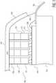
- FIG. 1shows, by way of illustrative and non-limitative example, a matrix transducer 100 usable in an ultrasound probe according to the present invention.
- the matrix transducer 100has a piezoelectric layer 110, three matching layers 120, 130, 140, a film 150 that incorporates the third matching layer 140, an interconnect layer 155, one or more semiconductor chips (ICs) 160 and a backing 165.
- the piezoelectric layer 110is comprised of a two-dimensional array 170 of transducer elements 175, rows being parallel to, and columns of the array being perpendicular to the drawing sheet for FIG. 1 .
- the transducer 100further includes a common ground plane 180 between the second and third matching layers 130, 140 that extends peripherally to wrap around downwardly for attachment to a flexible circuit 185, thereby completing circuits for individual transducer elements 175.
- the transducer element 175is joined to a semiconductor chip 160 by stud bumps 190 or other means, and the chip is connected to the flexible circuit 185.
- a coaxial cable (not shown) coming from the back of the ultrasound probetypically is joined to the flexible circuit 185.
- the matrix transducer 100may be utilized for transmitting ultrasound and/or receiving ultrasound.
- the first matching layer 120is implemented as a graphite composite.
- Epoxy matching layerstransmit sound with sufficient speed, and have density, and therefore acoustic impedance, that is sufficiently low for implementation as a second matching layer of a three-layer matrix transducer; however, epoxy layers are electrically non-conductive.
- the second matching layer 130is a polymer loaded with electrically-conductive particles.
- the third matching layer 140is made of low-density polyethylene (LDPE) and is part of the LDPE film 150 that extends downwardly in a manner similar to that of the common ground plane 180.
- LDPElow-density polyethylene
- the third matching layer 140 in the embodiment shown in FIG. 1attaches, by way of an epoxy bond 210, to a housing 220 of the transducer 100 to form a hermetic seal around the array 170.
- the epoxy bond 210also may be used between the transducer housing 220 and an acoustic lens 230 overriding the third matching layer 140.
- FIG. 3sets forth one example of a process for making the probe 100 of FIG. 1 so as to include LDPE film 110 embodying the third matching layer 140.
- piezoelectric material and the first two matching layers 120, 130are machined to the correct thicknesses and electrodes are applied to the piezoelectric layer 110 (step S310).
- the second matching layeris applied (step S330).
- This assembly of layers 110, 120, 130may be attached directly to the integrated circuits 160, if present, or to intermediary connecting means, e.g. the flexible circuit 185 or a backing structure with embedded conductors.
- the transducer 100then is separated into a 2D array 170 of individual elements 175 by making multiple saw cuts in two orthogonal directions (step S340).
- the ground plane 180is bonded to the top of the second matching layer 130 and wrapped down around the array 170 to make contact with the flexible circuit 185 or other connecting means.
- the LDPE film 110is applied on top and wrapped around to extend downwardly thereby surrounding the array 170. Part of the film 150 accordingly forms the topmost matching layer, which here is the third matching layer 140 (steps S350, S360).
- the downwardly extended film 150is bonded, as by epoxy 210, to the housing 220 (step S370).
- the LDPEalso serves as a barrier layer.
- RTVroom temperature vulcanization
- the first and second matching layers 120, 130may be bonded together before being applied as a unit to the piezoelectric material 110.
- the acoustic designmay call for one or more acoustic layers behind the piezoelectric layer 110.
- the acoustic lens 230is replaced with a window, i.e., an element with no focusing acoustical power.
- the windowmay be made of the window material PEBAX, for instance.
- PEBAXwindow material
- a PEBAX windowwould need not only a protective layer for the polyurethane third matching layer, but, in addition, an intervening bonding layer made, for example of a polyester material such as Mylar, to bond the protective layer to the PEBAX.
- LDPEcan bond directly to the PEBAX; accordingly, neither a protective layer nor a bonding layer is needed.
- the double layer of PEBAX window material and LDPE film 150can be made before attaching it to the second matching layer 130 connected to the array 170 by the first matching layer 120.
- the resulting transducer 100 with PEBAX windowis usable not only for trans-esophageal echocardiography (TEE), but for other applications such as an intra-cardiac-echocardiography (ICE).
- TEEtrans-esophageal echocardiography
- ICEintra-cardiac-echocardiography
- the LDPEcould be cut to size and not wrapped.
- the inventive matching layersmay be incorporated into other types of probes such as pediatric probes, and onto various types of arrays such as curved linear and vascular arrays.
Landscapes
- Physics & Mathematics (AREA)
- Engineering & Computer Science (AREA)
- Acoustics & Sound (AREA)
- Multimedia (AREA)
- Transducers For Ultrasonic Waves (AREA)
- Ultra Sonic Daignosis Equipment (AREA)
- Investigating Or Analyzing Materials By The Use Of Ultrasonic Waves (AREA)
Description
- An ultrasound transducer serves to convert electrical signals into ultrasonic energy and to convert ultrasonic energy back into electrical signals. The ultrasonic energy may be used, for example, to interrogate a body of interest and the echoes received from the body by the transducer may be used to obtain diagnostic information. One particular application is in medical imaging wherein the echoes are used to form two and three dimensional images of the internal organs of a patient. Ultrasound transducers use a matching layer or a series of matching layers to more effectively couple the acoustic energy produced in the piezoelectric to the body of the subject or patient. The matching layers lie above the transducer, in proximity of the body being probed. Acoustic coupling is accomplished, layer-by-layer, in a manner analogous to the functioning of respective anti-reflection coatings for lenses in an optical path. The relatively high acoustic impedance of the piezoelectric material in a transducer in comparison to that of the body is spanned by the intervening impedances of the matching layers. A design might, for example, call for a first matching layer of particular impedance. The first matching layer is the first layer encountered by the sound path from the transducer to the body. Each successive matching layer, if any, requires progressively lower impedance. The impedance of the topmost layer is still higher than that of the body, but the one or more layers provide a smoother transition, impedance-wise, in acoustically coupling the ultrasound generated by the piezoelectric to the body and in coupling the ultrasound returning from the body to the piezoelectric.
- Optimal layering involves a design of an appropriate series of acoustic impedances and the identification of respective materials. Materials used in the matching layers of one-dimensional (ID) transducers whose elements are aligned in a single row include ceramics, graphite composites, polyurethane, etc.
- Although 1D transducers have been known to include a number of matching layers, transducers configured with a two-dimensional (2D) array of transducer elements require a different matching layer scheme due to the different shape of the transducer elements. A traveling sound wave oscillates at a frequency characteristic of that particular sound wave, and the frequency has an associated wavelength. The elements of 1D array transducers are typically less than half a wavelength wide of the operating frequency in one transverse direction, but several wavelengths long in the other transverse direction. Elements of a 2D array transducer may be less than half a wavelength wide in both transverse directions. This change of shape reduces the effective longitudinal stiffness, and therefore, the mechanical impedance of the element. Since the element impedance is lower, it follows that the impedances of the matching layers also should be lower to achieve the best performance. A complicating factor of low impedance materials, however, is that when cut into narrow posts as in a 2D array transducer, the speed of sound becomes dependent on the frequency of the signal, a phenomenon known as velocity dispersion. This dispersion changes the matching properties of the layer with frequency, which is undesirable, and can create a cutoff frequency above which it is not possible to operate the transducer. 2D array transducers are currently built with only two matching layers, due to the lack of suitable materials for a three matching layer design. However, this limits the bandwidth and sensitivity, both of which are critical to improving performance in Doppler, color flow, and harmonic imaging modes. In the case of harmonic imaging, for example, a low fundamental frequency is transmitted to provide deeper penetration into the body tissue of the ultrasound subject or patient, but higher resolution is obtained by receiving harmonic frequencies above the fundamental. A bandwidth large enough to include diverse frequencies is therefore often desirable.
- The piezoelectric elements of 1D and 2D array transducers typically have been made of polycrystalline ceramic materials, one of the most common being lead zirconate titanate (PZT). Single-crystal piezoelectric materials are becoming available, e.g., mono-crystalline lead manganese niobate/lead titanate (PMN/PT) alloys. Piezoelectric transducer elements made from these monocrystalline materials, exhibit significantly higher electro-mechanical coupling which potentially affords improved sensitivity and bandwidth.
- The present inventors observe that the increased electro-mechanical coupling of single-crystal piezoelectrics also produces a lower effective acoustic impedance. As a result, it is preferable to select matching layers of acoustic impedance lower than those for a typical poly-crystalline transducer such as a ceramic one.
- Since the three matching layer, mono-crystalline transducer requires matching layers with lower acoustic impedances, and since the second matching layer of an ultrasound probe transducer is always of lower impedance than its first matching layer, it is possible that a second matching layer usable for ceramic transducers, such as graphite composite, may serve as a first matching layer for a three matching layer, mono-crystalline transducer.
- The first and second matching layers typically are stiff enough that the layers for each element of the array must be separated from each other mechanically to keep each element acoustically independent of the others. Most often, this is done by means of saw cuts in two directions that penetrate the two matching layers and the piezoelectric material.
- Another consideration may be electrical conductivity, which would not present a problem for isotropically conductive graphite composite.
- Finding a suitable second matching layer, however, may involve selecting a material with not only the proper acoustic impedance, but appropriate electrical conductivity.
- A piezoelectric transducer of an ultrasound probe relies upon electric fields produced in the piezoelectric. These fields are produced and detected by means of electrodes attached to at least two faces of the piezoelectric To generate ultrasound, for example, a voltage is applied between the electrodes requiring electrical connections to be made to the electrodes. Each element of the transducer might receive a different electrical input. Terminals to the transducer elements are sometimes attached perpendicularly to the sound path, although this can be problematic for internal elements of two-dimensional matrix arrays. Accordingly, it may be preferable to attach the elements to a common ground on top of, or under, the array. A matching layer may serve as a ground plane, or a separate ground plane may be provided. The ground plane may be implemented with an electrically-conductive foil thin enough to avoid perturbing the ultrasound.
- However, unless the separate ground plane is disposed between the first matching layer and the piezoelectric element, the first matching layer is preferably made electrically-conductive in the sound path direction in order to complete an electrical circuit that flows from behind and through the array. Because the 2D array elements are mechanically separated, e.g. by saw cuts in two directions producing individual posts, there is no electrical path for an element in the interior of the array laterally to the edge of the array. Accordingly, the electrical path must be completed through the matching layer. The same principle holds for the second matching layer.
- Polyurethane, with an acoustic impedance of around 2.1 MegaRayls (MRayls), might serve as a third matching layer, which requires the lower impedance than the first or second layers. However, besides having an impedance somewhat higher than that desired, polyurethane is very susceptible to chemical reaction. Accordingly, polyurethane requires a protective coating to seal the polyurethane and the rest of the transducer array from environmental contamination as from chemical disinfecting agents and humidity. Moreover, from a process control perspective, different production runs may yield different thicknesses of the protective coating, leading to uneven acoustic performance among produced probes. Finally, the need for a separate process to apply the protective coating increases production cost enormously.
EP 1 542 005 A1 discloses an ultrasonic probe including a piezoelectric oscillator layer having plural arranged piezoelectric oscillators for transmitting and receiving ultrasonic waves and plural electrodes formed in the piezoelectric oscillators, an acoustic lens for focusing or diffusing the ultrasonic waves, and an acoustic matching layer that is provided between the piezoelectric oscillator layer and the acoustic lens and includes a resin base and fine particles, which have electric conductivity, mixed in the resin base. Further exemplary layer designs of ultrasonic probes are known fromEP 1 132 149 A2 ,US 6,194,814 B1 ,EP 1 642 531 A ,JP S61 169100 A US 4,143,554 A ,US 2005/165313 A1 , and fromWO 2004/093725 A2 . - To overcome the above-noted shortcomings, an ultrasound transducer, according to claim 1 is presented which includes a piezoelectric element, and first through third matching layers. The first matching layer is arranged on the piezoelectric element, made of a graphite composite; the second matching layer is arranged on the first matching layer, made of a polymer loaded with electrically-conductive particles; and the third matching layer is arranged on the second matching layer. The ultrasound transducer further comprises a low-density polyethylene (LDPE) film that includes said third matching layer and extends downwardly to surround said piezoelectric element. In another aspect, a method according to claim 3 is provided.
- Details of the novel ultrasound probe are set forth below with the aid of the following drawings, wherein:
FIG. 1 is a side cross-sectional view of a matrix transducer having three matching layers, according to the present invention;FIG. 2 is side cross-sectional view of an example of how the third matching layer is bonded to the transducer housing; andFIG. 3 is a flow chart of one example of a process for making the transducer ofFIG. 1 .FIG. 1 shows, by way of illustrative and non-limitative example, amatrix transducer 100 usable in an ultrasound probe according to the present invention. Thematrix transducer 100 has apiezoelectric layer 110, threematching layers film 150 that incorporates thethird matching layer 140, aninterconnect layer 155, one or more semiconductor chips (ICs) 160 and abacking 165. Thepiezoelectric layer 110 is comprised of a two-dimensional array 170 oftransducer elements 175, rows being parallel to, and columns of the array being perpendicular to the drawing sheet forFIG. 1 . Thetransducer 100 further includes acommon ground plane 180 between the second and third matching layers 130, 140 that extends peripherally to wrap around downwardly for attachment to aflexible circuit 185, thereby completing circuits forindividual transducer elements 175. Specifically, thetransducer element 175 is joined to asemiconductor chip 160 bystud bumps 190 or other means, and the chip is connected to theflexible circuit 185. A coaxial cable (not shown) coming
from the back of the ultrasound probe typically is joined to theflexible circuit 185. Thematrix transducer 100 may be utilized for transmitting ultrasound and/or receiving ultrasound.- The
first matching layer 120, as mentioned above, is implemented as a graphite composite. - Epoxy matching layers transmit sound with sufficient speed, and have density, and therefore acoustic impedance, that is sufficiently low for implementation as a second matching layer of a three-layer matrix transducer; however, epoxy layers are electrically non-conductive.
- The
second matching layer 130 is a polymer loaded with electrically-conductive particles. - The
third matching layer 140 is made of low-density polyethylene (LDPE) and is part of theLDPE film 150 that extends downwardly in a manner similar to that of thecommon ground plane 180. - As seen in
FIG. 2 , however, instead of attaching to theflexible circuit 185, thethird matching layer 140 in the embodiment shown inFIG. 1 attaches, by way of anepoxy bond 210, to ahousing 220 of thetransducer 100 to form a hermetic seal around thearray 170. Theepoxy bond 210 also may be used between thetransducer housing 220 and anacoustic lens 230 overriding thethird matching layer 140. FIG. 3 sets forth one example of a process for making theprobe 100 ofFIG. 1 so as to includeLDPE film 110 embodying thethird matching layer 140. To construct thearray 170, piezoelectric material and the first two matchinglayers first matching layer 120 is applied on top of the piezoelectric layer 110 (step S320), the second matching layer is applied (step S330). This assembly oflayers integrated circuits 160, if present, or to intermediary connecting means, e.g. theflexible circuit 185 or a backing structure with embedded conductors. Thetransducer 100 then is separated into a2D array 170 ofindividual elements 175 by making multiple saw cuts in two orthogonal directions (step S340). Following the sawing operation, theground plane 180 is bonded to the top of thesecond matching layer 130 and wrapped down around thearray 170 to make contact with theflexible circuit 185 or other connecting means. TheLDPE film 110 is applied on top and wrapped around to extend downwardly thereby surrounding thearray 170. Part of thefilm 150 accordingly forms the topmost matching layer, which here is the third matching layer 140 (steps S350, S360). To form a hermetic seal around thearray 170, the downwardly extendedfilm 150 is bonded, as byepoxy 210, to the housing 220 (step S370). Thus, the LDPE also serves as a barrier layer. An additional step bonds theacoustic lens 230, typically a room temperature vulcanization (RTV) silicone rubber, to the third matching layer 140 (step S380). As compared to polyurethane, use of polyethylene as thethird matching layer 140 eliminates the need for a protective coating, thereby cutting production cost dramatically.- Although a particular order of the steps in
FIG. 3 is shown, the intended scope of the invention is not limited to this order. Thus, for example, the first and second matching layers 120, 130 may be bonded together before being applied as a unit to thepiezoelectric material 110. Additionally, the acoustic design may call for one or more acoustic layers behind thepiezoelectric layer 110. - In an alternative embodiment of the present invention, the
acoustic lens 230 is replaced with a window, i.e., an element with no focusing acoustical power. The window may be made of the window material PEBAX, for instance. Normally, a PEBAX window would need not only a protective layer for the polyurethane third matching layer, but, in addition, an intervening bonding layer made, for example of a polyester material such as Mylar, to bond the protective layer to the PEBAX. However, LDPE can bond directly to the PEBAX; accordingly, neither a protective layer nor a bonding layer is needed. The double layer of PEBAX window material andLDPE film 150 can be made before attaching it to thesecond matching layer 130 connected to thearray 170 by thefirst matching layer 120. The resultingtransducer 100 with PEBAX window is usable not only for trans-esophageal echocardiography (TEE), but for other applications such as an intra-cardiac-echocardiography (ICE). Optionally, to meet size constraints, the LDPE could be cut to size and not wrapped. - The inventive matching layers may be incorporated into other types of probes such as pediatric probes, and onto various types of arrays such as curved linear and vascular arrays.
- Although above embodiments are described with three matching layers, additional matching layers may intervene, as between the second and topmost matching layers 130, 140.
Claims (4)
- An ultrasound transducer (100) comprising:a piezoelectric element (175) andcharacterized in that it further comprisesa first matching layer (120) arranged on the piezoelectric element (175), made of a graphite composite;a second matching layer (130) arranged on the first matching layer (120), made of a polymer loaded with electrically-conductive particles; anda third matching layer (140) arranged on the second matching layer (130);wherein the ultrasound transducer (100) comprises a low-density polyethylene (LDPE) film (150) that includes said third matching layer (140) and extends downwardly to surround said piezoelectric element (175).
- The transducer of claim 1, wherein said LDPE film (150) forms part of a seal around said piezoelectric element (175).
- A method of making an ultrasound transducer (100) comprising:providing a piezoelectric element (175); and beingcharacterized in that it further comprisesfurnishing the element with three matching layers (120, 130, 140) by arranging a first matching layer (120) made of a graphite composite on the piezoelectric element (175), a second matching layer (130) made of a polymer loaded with electrically-conductive particles on the first matching layer (120), and a third matching layer (140) on the second matching layer (130);wherein furnishing furnishes a low-density polyethylene (LDPE) film (150) that includes said third matching layer (140) and extends downwardly to surround said piezoelectric element (175).
- The method of claim 3, wherein said LDPE film (150) forms part of a seal (210) around said piezoelectric element (175).
Applications Claiming Priority (2)
| Application Number | Priority Date | Filing Date | Title |
|---|---|---|---|
| US70639905P | 2005-08-08 | 2005-08-08 | |
| PCT/IB2006/052476WO2007017776A2 (en) | 2005-08-08 | 2006-07-19 | Wide-bandwidth matrix transducer with polyethylene third matching layer |
Publications (2)
| Publication Number | Publication Date |
|---|---|
| EP1915753A2 EP1915753A2 (en) | 2008-04-30 |
| EP1915753B1true EP1915753B1 (en) | 2019-04-10 |
Family
ID=37727690
Family Applications (1)
| Application Number | Title | Priority Date | Filing Date |
|---|---|---|---|
| EP06780138.1AActiveEP1915753B1 (en) | 2005-08-08 | 2006-07-19 | Wide-bandwidth matrix transducer with polyethylene third matching layer |
Country Status (6)
| Country | Link |
|---|---|
| US (1) | US8030824B2 (en) |
| EP (1) | EP1915753B1 (en) |
| JP (1) | JP2009505468A (en) |
| CN (1) | CN101238506A (en) |
| RU (1) | RU2418384C2 (en) |
| WO (1) | WO2007017776A2 (en) |
Families Citing this family (18)
| Publication number | Priority date | Publication date | Assignee | Title |
|---|---|---|---|---|
| US7804228B2 (en) | 2007-12-18 | 2010-09-28 | Boston Scientific Scimed, Inc. | Composite passive materials for ultrasound transducers |
| US8390174B2 (en) | 2007-12-27 | 2013-03-05 | Boston Scientific Scimed, Inc. | Connections for ultrasound transducers |
| WO2011033421A1 (en) | 2009-09-15 | 2011-03-24 | Koninklijke Philips Electronics N.V. | Medical ultrasound device with force detection |
| US8232705B2 (en)* | 2010-07-09 | 2012-07-31 | General Electric Company | Thermal transfer and acoustic matching layers for ultrasound transducer |
| US9237880B2 (en) | 2011-03-17 | 2016-01-19 | Koninklijke Philips N.V. | Composite acoustic backing with high thermal conductivity for ultrasound transducer array |
| US9579078B2 (en)* | 2011-09-22 | 2017-02-28 | Koninklijke Philips N.V. | Excitation schemes for low-cost transducer arrays |
| NL2008459C2 (en)* | 2012-03-09 | 2013-09-10 | Oldelft B V | A method of manufacturing an ultrasound transducer for use in an ultrasound imaging device, and an ultrasound transducer and ultrasound probe manufactured according to the method. |
| WO2015068080A1 (en) | 2013-11-11 | 2015-05-14 | Koninklijke Philips N.V. | Robust ultrasound transducer probes having protected integrated circuit interconnects |
| WO2015145296A1 (en) | 2014-03-27 | 2015-10-01 | Koninklijke Philips N.V. | Ultrasound probes and systems having pin-pmn-pt, a dematching layer, and improved thermally conductive backing materials |
| WO2015145402A1 (en) | 2014-03-27 | 2015-10-01 | Koninklijke Philips N.V. | Thermally conductive backing materials for ultrasound probes and systems |
| US9789515B2 (en)* | 2014-05-30 | 2017-10-17 | Fujifilm Dimatix, Inc. | Piezoelectric transducer device with lens structures |
| EP3028772B1 (en) | 2014-12-02 | 2022-12-28 | Samsung Medison Co., Ltd. | Ultrasonic probe and method of manufacturing the same |
| KR102406927B1 (en)* | 2014-12-02 | 2022-06-10 | 삼성메디슨 주식회사 | Ultrasound probe and manufacturing method for the same |
| CN109952768B (en)* | 2016-09-09 | 2021-01-08 | 安科诺思公司 | Flexible circuit with redundant connection points for ultrasound arrays |
| US11756520B2 (en)* | 2016-11-22 | 2023-09-12 | Transducer Works LLC | 2D ultrasound transducer array and methods of making the same |
| CN110300631B (en) | 2017-02-24 | 2021-09-24 | 传感频谱有限责任公司 | Ultrasound equipment that includes acoustically matched areas |
| CN110680390A (en)* | 2019-10-25 | 2020-01-14 | 飞依诺科技(苏州)有限公司 | Ultrasonic transducer and preparation method thereof |
| JP7527680B2 (en)* | 2021-01-06 | 2024-08-05 | 国立大学法人 東京大学 | Ultrasonic device, impedance matching layer and electrostatically actuated device |
Citations (5)
| Publication number | Priority date | Publication date | Assignee | Title |
|---|---|---|---|---|
| US4143554A (en)* | 1977-03-14 | 1979-03-13 | Second Foundation | Ultrasonic scanner |
| JPS61169100A (en)* | 1985-01-22 | 1986-07-30 | Matsushita Electric Ind Co Ltd | Ultrasonic transmitter-receiver |
| US6194814B1 (en)* | 1998-06-08 | 2001-02-27 | Acuson Corporation | Nosepiece having an integrated faceplate window for phased-array acoustic transducers |
| WO2004093725A2 (en)* | 2003-04-16 | 2004-11-04 | Cytodome, Inc. | Implantable ultrasound systems and methods for enhancing localized delivery of therapeutic substances |
| US20050165313A1 (en)* | 2004-01-26 | 2005-07-28 | Byron Jacquelyn M. | Transducer assembly for ultrasound probes |
Family Cites Families (16)
| Publication number | Priority date | Publication date | Assignee | Title |
|---|---|---|---|---|
| US2949910A (en)* | 1957-03-29 | 1960-08-23 | James R Brown | Phonocardiac catheter |
| AT353506B (en)* | 1976-10-19 | 1979-11-26 | List Hans | PIEZOELECTRIC RESONATOR |
| JPS6373939A (en)* | 1986-09-17 | 1988-04-04 | 富士通株式会社 | Manufacturing method of ultrasonic probe |
| DE4028315A1 (en)* | 1990-09-06 | 1992-03-12 | Siemens Ag | ULTRASONIC CONVERTER FOR THE RUN TIME MEASUREMENT OF ULTRASONIC IMPULSES IN A GAS |
| JP2814903B2 (en)* | 1993-12-22 | 1998-10-27 | 松下電器産業株式会社 | Ultrasonic probe |
| RU2078340C1 (en)* | 1994-02-08 | 1997-04-27 | Научно-исследовательский институт радиоэлектроники и лазерной техники Московского государственного технического университета им.Н.Э.Баумана | Piezoelectric transformer (bimorph) for ultrasonic diagnostic catheter |
| EP1218115B1 (en)* | 1999-07-02 | 2005-02-16 | Prosonic Company Ltd. | Ultrasonic linear or curvilinear transducer and connection technique therefore |
| JP2001245883A (en)* | 2000-03-07 | 2001-09-11 | Matsushita Electric Ind Co Ltd | Ultrasonic probe |
| CA2332158C (en)* | 2000-03-07 | 2004-09-14 | Matsushita Electric Industrial Co., Ltd. | Ultrasonic probe |
| JP3595755B2 (en)* | 2000-03-28 | 2004-12-02 | 松下電器産業株式会社 | Ultrasonic probe |
| FR2818170B1 (en) | 2000-12-19 | 2003-03-07 | Thomson Csf | METHOD OF MANUFACTURING A MULTI-ELEMENT ACOUSTIC PROBE USING A METALLIC AND ABLATE POLYMER FILM AS A GROUND PLAN |
| US6666825B2 (en)* | 2001-07-05 | 2003-12-23 | General Electric Company | Ultrasound transducer for improving resolution in imaging system |
| JP2004029038A (en)* | 2002-01-28 | 2004-01-29 | Matsushita Electric Ind Co Ltd | Ultrasonic flow meter |
| DE602004004488T2 (en)* | 2003-12-09 | 2007-10-31 | Kabushiki Kaisha Toshiba | Ultrasonic probe with conductive acoustic matching layer |
| JP4528606B2 (en)* | 2003-12-09 | 2010-08-18 | 株式会社東芝 | Ultrasonic probe and ultrasonic diagnostic apparatus |
| JP4181103B2 (en)* | 2004-09-30 | 2008-11-12 | 株式会社東芝 | Ultrasonic probe and ultrasonic diagnostic apparatus |
- 2006
- 2006-07-19CNCNA2006800291138Apatent/CN101238506A/enactivePending
- 2006-07-19WOPCT/IB2006/052476patent/WO2007017776A2/enactiveApplication Filing
- 2006-07-19EPEP06780138.1Apatent/EP1915753B1/enactiveActive
- 2006-07-19RURU2008108989/28Apatent/RU2418384C2/ennot_activeIP Right Cessation
- 2006-07-19JPJP2008525670Apatent/JP2009505468A/ennot_activeCeased
- 2006-07-19USUS12/063,294patent/US8030824B2/enactiveActive
Patent Citations (5)
| Publication number | Priority date | Publication date | Assignee | Title |
|---|---|---|---|---|
| US4143554A (en)* | 1977-03-14 | 1979-03-13 | Second Foundation | Ultrasonic scanner |
| JPS61169100A (en)* | 1985-01-22 | 1986-07-30 | Matsushita Electric Ind Co Ltd | Ultrasonic transmitter-receiver |
| US6194814B1 (en)* | 1998-06-08 | 2001-02-27 | Acuson Corporation | Nosepiece having an integrated faceplate window for phased-array acoustic transducers |
| WO2004093725A2 (en)* | 2003-04-16 | 2004-11-04 | Cytodome, Inc. | Implantable ultrasound systems and methods for enhancing localized delivery of therapeutic substances |
| US20050165313A1 (en)* | 2004-01-26 | 2005-07-28 | Byron Jacquelyn M. | Transducer assembly for ultrasound probes |
Also Published As
| Publication number | Publication date |
|---|---|
| WO2007017776A2 (en) | 2007-02-15 |
| US8030824B2 (en) | 2011-10-04 |
| RU2418384C2 (en) | 2011-05-10 |
| US20100168581A1 (en) | 2010-07-01 |
| JP2009505468A (en) | 2009-02-05 |
| RU2008108989A (en) | 2009-09-20 |
| CN101238506A (en) | 2008-08-06 |
| EP1915753A2 (en) | 2008-04-30 |
| WO2007017776A3 (en) | 2007-12-06 |
Similar Documents
| Publication | Publication Date | Title |
|---|---|---|
| EP1915753B1 (en) | Wide-bandwidth matrix transducer with polyethylene third matching layer | |
| US7859170B2 (en) | Wide-bandwidth matrix transducer with polyethylene third matching layer | |
| US10770058B2 (en) | Acoustic lens for micromachined ultrasound transducers | |
| US5894646A (en) | Method for the manufacture of a two dimensional acoustic array | |
| US6758094B2 (en) | Ultrasonic transducer wafer having variable acoustic impedance | |
| EP2346269B1 (en) | Acoustic oscillator | |
| US7288069B2 (en) | Ultrasonic probe and method of manufacturing the same | |
| JP4933392B2 (en) | Ultrasonic probe and manufacturing method thereof | |
| US20080238259A1 (en) | Ultrasonic probe and production method thereof | |
| AU2015287366B2 (en) | Multi-cell transducer | |
| JP2018530196A (en) | Capacitive micromachined ultrasonic transducer with increased lifetime | |
| US9839411B2 (en) | Ultrasound diagnostic apparatus probe having laminated piezoelectric layers oriented at different angles | |
| US20190110773A1 (en) | Ultrasound endoscope and methods of manufacture thereof | |
| US20020096973A1 (en) | Class V flextensional transducer with directional beam patterns | |
| JP2000358299A (en) | Wave transmitting and receiving element for ultrasonic probe, its production method and ultrasonic probe using the same element | |
| US5757727A (en) | Two-dimensional acoustic array and method for the manufacture thereof | |
| JP2011067485A (en) | Ultrasonic transducer and probe | |
| KR20150073056A (en) | Ultrasonic diagnostic instrument and manufacturing method thereof | |
| WO2014077061A1 (en) | Ultrasonic vibrator and manufacturing method therefor | |
| JP2011062224A (en) | Ultrasonic transducer and ultrasonic probe | |
| KR102359155B1 (en) | Hybrid ultrasound prove array and method of manufacturing the same | |
| JP5530994B2 (en) | Ultrasonic probe and manufacturing method thereof |
Legal Events
| Date | Code | Title | Description |
|---|---|---|---|
| PUAI | Public reference made under article 153(3) epc to a published international application that has entered the european phase | Free format text:ORIGINAL CODE: 0009012 | |
| AK | Designated contracting states | Kind code of ref document:A2 Designated state(s):AT BE BG CH CY CZ DE DK EE ES FI FR GB GR HU IE IS IT LI LT LU LV MC NL PL PT RO SE SI SK TR | |
| AX | Request for extension of the european patent | Extension state:AL BA HR MK RS | |
| 17P | Request for examination filed | Effective date:20080606 | |
| RBV | Designated contracting states (corrected) | Designated state(s):AT BE BG CH CY CZ DE DK EE ES FI FR GB GR HU IE IS IT LI LT LU LV MC NL PL PT RO SE SI SK TR | |
| DAX | Request for extension of the european patent (deleted) | ||
| RAP1 | Party data changed (applicant data changed or rights of an application transferred) | Owner name:KONINKLIJKE PHILIPS N.V. | |
| STAA | Information on the status of an ep patent application or granted ep patent | Free format text:STATUS: EXAMINATION IS IN PROGRESS | |
| 17Q | First examination report despatched | Effective date:20170602 | |
| GRAP | Despatch of communication of intention to grant a patent | Free format text:ORIGINAL CODE: EPIDOSNIGR1 | |
| STAA | Information on the status of an ep patent application or granted ep patent | Free format text:STATUS: GRANT OF PATENT IS INTENDED | |
| INTG | Intention to grant announced | Effective date:20181026 | |
| GRAS | Grant fee paid | Free format text:ORIGINAL CODE: EPIDOSNIGR3 | |
| GRAA | (expected) grant | Free format text:ORIGINAL CODE: 0009210 | |
| STAA | Information on the status of an ep patent application or granted ep patent | Free format text:STATUS: THE PATENT HAS BEEN GRANTED | |
| AK | Designated contracting states | Kind code of ref document:B1 Designated state(s):AT BE BG CH CY CZ DE DK EE ES FI FR GB GR HU IE IS IT LI LT LU LV MC NL PL PT RO SE SI SK TR | |
| REG | Reference to a national code | Ref country code:GB Ref legal event code:FG4D | |
| REG | Reference to a national code | Ref country code:CH Ref legal event code:EP Ref country code:AT Ref legal event code:REF Ref document number:1119759 Country of ref document:AT Kind code of ref document:T Effective date:20190415 | |
| REG | Reference to a national code | Ref country code:DE Ref legal event code:R096 Ref document number:602006057758 Country of ref document:DE | |
| REG | Reference to a national code | Ref country code:IE Ref legal event code:FG4D | |
| REG | Reference to a national code | Ref country code:DE Ref legal event code:R084 Ref document number:602006057758 Country of ref document:DE | |
| REG | Reference to a national code | Ref country code:NL Ref legal event code:MP Effective date:20190410 | |
| REG | Reference to a national code | Ref country code:LT Ref legal event code:MG4D | |
| REG | Reference to a national code | Ref country code:GB Ref legal event code:746 Effective date:20190821 | |
| REG | Reference to a national code | Ref country code:AT Ref legal event code:MK05 Ref document number:1119759 Country of ref document:AT Kind code of ref document:T Effective date:20190410 | |
| PG25 | Lapsed in a contracting state [announced via postgrant information from national office to epo] | Ref country code:NL Free format text:LAPSE BECAUSE OF FAILURE TO SUBMIT A TRANSLATION OF THE DESCRIPTION OR TO PAY THE FEE WITHIN THE PRESCRIBED TIME-LIMIT Effective date:20190410 | |
| PG25 | Lapsed in a contracting state [announced via postgrant information from national office to epo] | Ref country code:ES Free format text:LAPSE BECAUSE OF FAILURE TO SUBMIT A TRANSLATION OF THE DESCRIPTION OR TO PAY THE FEE WITHIN THE PRESCRIBED TIME-LIMIT Effective date:20190410 Ref country code:PT Free format text:LAPSE BECAUSE OF FAILURE TO SUBMIT A TRANSLATION OF THE DESCRIPTION OR TO PAY THE FEE WITHIN THE PRESCRIBED TIME-LIMIT Effective date:20190910 Ref country code:SE Free format text:LAPSE BECAUSE OF FAILURE TO SUBMIT A TRANSLATION OF THE DESCRIPTION OR TO PAY THE FEE WITHIN THE PRESCRIBED TIME-LIMIT Effective date:20190410 Ref country code:FI Free format text:LAPSE BECAUSE OF FAILURE TO SUBMIT A TRANSLATION OF THE DESCRIPTION OR TO PAY THE FEE WITHIN THE PRESCRIBED TIME-LIMIT Effective date:20190410 Ref country code:LT Free format text:LAPSE BECAUSE OF FAILURE TO SUBMIT A TRANSLATION OF THE DESCRIPTION OR TO PAY THE FEE WITHIN THE PRESCRIBED TIME-LIMIT Effective date:20190410 | |
| PG25 | Lapsed in a contracting state [announced via postgrant information from national office to epo] | Ref country code:LV Free format text:LAPSE BECAUSE OF FAILURE TO SUBMIT A TRANSLATION OF THE DESCRIPTION OR TO PAY THE FEE WITHIN THE PRESCRIBED TIME-LIMIT Effective date:20190410 Ref country code:BG Free format text:LAPSE BECAUSE OF FAILURE TO SUBMIT A TRANSLATION OF THE DESCRIPTION OR TO PAY THE FEE WITHIN THE PRESCRIBED TIME-LIMIT Effective date:20190710 Ref country code:GR Free format text:LAPSE BECAUSE OF FAILURE TO SUBMIT A TRANSLATION OF THE DESCRIPTION OR TO PAY THE FEE WITHIN THE PRESCRIBED TIME-LIMIT Effective date:20190711 Ref country code:PL Free format text:LAPSE BECAUSE OF FAILURE TO SUBMIT A TRANSLATION OF THE DESCRIPTION OR TO PAY THE FEE WITHIN THE PRESCRIBED TIME-LIMIT Effective date:20190410 | |
| PG25 | Lapsed in a contracting state [announced via postgrant information from national office to epo] | Ref country code:IS Free format text:LAPSE BECAUSE OF FAILURE TO SUBMIT A TRANSLATION OF THE DESCRIPTION OR TO PAY THE FEE WITHIN THE PRESCRIBED TIME-LIMIT Effective date:20190810 Ref country code:AT Free format text:LAPSE BECAUSE OF FAILURE TO SUBMIT A TRANSLATION OF THE DESCRIPTION OR TO PAY THE FEE WITHIN THE PRESCRIBED TIME-LIMIT Effective date:20190410 | |
| REG | Reference to a national code | Ref country code:DE Ref legal event code:R097 Ref document number:602006057758 Country of ref document:DE | |
| PG25 | Lapsed in a contracting state [announced via postgrant information from national office to epo] | Ref country code:EE Free format text:LAPSE BECAUSE OF FAILURE TO SUBMIT A TRANSLATION OF THE DESCRIPTION OR TO PAY THE FEE WITHIN THE PRESCRIBED TIME-LIMIT Effective date:20190410 Ref country code:DK Free format text:LAPSE BECAUSE OF FAILURE TO SUBMIT A TRANSLATION OF THE DESCRIPTION OR TO PAY THE FEE WITHIN THE PRESCRIBED TIME-LIMIT Effective date:20190410 Ref country code:SK Free format text:LAPSE BECAUSE OF FAILURE TO SUBMIT A TRANSLATION OF THE DESCRIPTION OR TO PAY THE FEE WITHIN THE PRESCRIBED TIME-LIMIT Effective date:20190410 Ref country code:RO Free format text:LAPSE BECAUSE OF FAILURE TO SUBMIT A TRANSLATION OF THE DESCRIPTION OR TO PAY THE FEE WITHIN THE PRESCRIBED TIME-LIMIT Effective date:20190410 Ref country code:CZ Free format text:LAPSE BECAUSE OF FAILURE TO SUBMIT A TRANSLATION OF THE DESCRIPTION OR TO PAY THE FEE WITHIN THE PRESCRIBED TIME-LIMIT Effective date:20190410 | |
| PLBE | No opposition filed within time limit | Free format text:ORIGINAL CODE: 0009261 | |
| STAA | Information on the status of an ep patent application or granted ep patent | Free format text:STATUS: NO OPPOSITION FILED WITHIN TIME LIMIT | |
| PG25 | Lapsed in a contracting state [announced via postgrant information from national office to epo] | Ref country code:MC Free format text:LAPSE BECAUSE OF FAILURE TO SUBMIT A TRANSLATION OF THE DESCRIPTION OR TO PAY THE FEE WITHIN THE PRESCRIBED TIME-LIMIT Effective date:20190410 Ref country code:IT Free format text:LAPSE BECAUSE OF FAILURE TO SUBMIT A TRANSLATION OF THE DESCRIPTION OR TO PAY THE FEE WITHIN THE PRESCRIBED TIME-LIMIT Effective date:20190410 | |
| REG | Reference to a national code | Ref country code:CH Ref legal event code:PL | |
| 26N | No opposition filed | Effective date:20200113 | |
| PG25 | Lapsed in a contracting state [announced via postgrant information from national office to epo] | Ref country code:TR Free format text:LAPSE BECAUSE OF FAILURE TO SUBMIT A TRANSLATION OF THE DESCRIPTION OR TO PAY THE FEE WITHIN THE PRESCRIBED TIME-LIMIT Effective date:20190410 | |
| REG | Reference to a national code | Ref country code:BE Ref legal event code:MM Effective date:20190731 | |
| PG25 | Lapsed in a contracting state [announced via postgrant information from national office to epo] | Ref country code:BE Free format text:LAPSE BECAUSE OF NON-PAYMENT OF DUE FEES Effective date:20190731 Ref country code:CH Free format text:LAPSE BECAUSE OF NON-PAYMENT OF DUE FEES Effective date:20190731 Ref country code:SI Free format text:LAPSE BECAUSE OF FAILURE TO SUBMIT A TRANSLATION OF THE DESCRIPTION OR TO PAY THE FEE WITHIN THE PRESCRIBED TIME-LIMIT Effective date:20190410 Ref country code:LU Free format text:LAPSE BECAUSE OF NON-PAYMENT OF DUE FEES Effective date:20190719 Ref country code:LI Free format text:LAPSE BECAUSE OF NON-PAYMENT OF DUE FEES Effective date:20190731 | |
| PG25 | Lapsed in a contracting state [announced via postgrant information from national office to epo] | Ref country code:IE Free format text:LAPSE BECAUSE OF NON-PAYMENT OF DUE FEES Effective date:20190719 | |
| PG25 | Lapsed in a contracting state [announced via postgrant information from national office to epo] | Ref country code:CY Free format text:LAPSE BECAUSE OF FAILURE TO SUBMIT A TRANSLATION OF THE DESCRIPTION OR TO PAY THE FEE WITHIN THE PRESCRIBED TIME-LIMIT Effective date:20190410 | |
| PG25 | Lapsed in a contracting state [announced via postgrant information from national office to epo] | Ref country code:HU Free format text:LAPSE BECAUSE OF FAILURE TO SUBMIT A TRANSLATION OF THE DESCRIPTION OR TO PAY THE FEE WITHIN THE PRESCRIBED TIME-LIMIT; INVALID AB INITIO Effective date:20060719 | |
| P01 | Opt-out of the competence of the unified patent court (upc) registered | Effective date:20230522 | |
| PGFP | Annual fee paid to national office [announced via postgrant information from national office to epo] | Ref country code:GB Payment date:20230725 Year of fee payment:18 | |
| PGFP | Annual fee paid to national office [announced via postgrant information from national office to epo] | Ref country code:FR Payment date:20230725 Year of fee payment:18 | |
| PGFP | Annual fee paid to national office [announced via postgrant information from national office to epo] | Ref country code:DE Payment date:20240730 Year of fee payment:19 | |
| GBPC | Gb: european patent ceased through non-payment of renewal fee | Effective date:20240719 | |
| PG25 | Lapsed in a contracting state [announced via postgrant information from national office to epo] | Ref country code:FR Free format text:LAPSE BECAUSE OF NON-PAYMENT OF DUE FEES Effective date:20240731 | |
| PG25 | Lapsed in a contracting state [announced via postgrant information from national office to epo] | Ref country code:GB Free format text:LAPSE BECAUSE OF NON-PAYMENT OF DUE FEES Effective date:20240719 |