EP1911927B1 - Method and apparatus for displacing drilling fluids with completion and workover fluids - Google Patents
Method and apparatus for displacing drilling fluids with completion and workover fluidsDownload PDFInfo
- Publication number
- EP1911927B1 EP1911927B1EP07120932AEP07120932AEP1911927B1EP 1911927 B1EP1911927 B1EP 1911927B1EP 07120932 AEP07120932 AEP 07120932AEP 07120932 AEP07120932 AEP 07120932AEP 1911927 B1EP1911927 B1EP 1911927B1
- Authority
- EP
- European Patent Office
- Prior art keywords
- fluid
- casing
- string
- completion
- swab cups
- Prior art date
- Legal status (The legal status is an assumption and is not a legal conclusion. Google has not performed a legal analysis and makes no representation as to the accuracy of the status listed.)
- Expired - Lifetime
Links
- 239000012530fluidSubstances0.000titleclaimsabstractdescription175
- 238000005553drillingMethods0.000titleclaimsabstractdescription69
- 238000000034methodMethods0.000titleclaimsdescription22
- VNDYJBBGRKZCSX-UHFFFAOYSA-Lzinc bromideChemical compoundBr[Zn]BrVNDYJBBGRKZCSX-UHFFFAOYSA-L0.000claimsdescription4
- 238000005086pumpingMethods0.000claimsdescription3
- UXVMQQNJUSDDNG-UHFFFAOYSA-LCalcium chlorideChemical class[Cl-].[Cl-].[Ca+2]UXVMQQNJUSDDNG-UHFFFAOYSA-L0.000claimsdescription2
- 229910001622calcium bromideInorganic materials0.000claimsdescription2
- WGEFECGEFUFIQW-UHFFFAOYSA-Lcalcium dibromideChemical compound[Ca+2].[Br-].[Br-]WGEFECGEFUFIQW-UHFFFAOYSA-L0.000claimsdescription2
- 239000000203mixtureSubstances0.000claimsdescription2
- 229940102001zinc bromideDrugs0.000claimsdescription2
- 238000007790scrapingMethods0.000claims1
- 238000000926separation methodMethods0.000abstractdescription13
- 230000002441reversible effectEffects0.000abstractdescription6
- 238000004140cleaningMethods0.000description16
- 238000006073displacement reactionMethods0.000description16
- 125000006850spacer groupChemical group0.000description16
- 230000015572biosynthetic processEffects0.000description12
- 238000005755formation reactionMethods0.000description12
- 229910000831SteelInorganic materials0.000description9
- 239000010959steelSubstances0.000description9
- 238000004519manufacturing processMethods0.000description8
- 239000000126substanceSubstances0.000description8
- 230000002829reductive effectEffects0.000description6
- 230000008569processEffects0.000description5
- XLYOFNOQVPJJNP-UHFFFAOYSA-NwaterSubstancesOXLYOFNOQVPJJNP-UHFFFAOYSA-N0.000description5
- 230000004888barrier functionEffects0.000description4
- 230000002706hydrostatic effectEffects0.000description4
- 238000012856packingMethods0.000description4
- 239000004568cementSubstances0.000description3
- 239000012267brineSubstances0.000description2
- 244000309464bullSpecies0.000description2
- 238000011010flushing procedureMethods0.000description2
- 229910052751metalInorganic materials0.000description2
- 239000002184metalSubstances0.000description2
- 230000000284resting effectEffects0.000description2
- 150000003839saltsChemical class0.000description2
- 238000007789sealingMethods0.000description2
- 238000010008shearingMethods0.000description2
- HPALAKNZSZLMCH-UHFFFAOYSA-Msodium;chloride;hydrateChemical compoundO.[Na+].[Cl-]HPALAKNZSZLMCH-UHFFFAOYSA-M0.000description2
- 239000002253acidSubstances0.000description1
- 230000009471actionEffects0.000description1
- 229910001628calcium chlorideInorganic materials0.000description1
- 239000001110calcium chlorideSubstances0.000description1
- 239000013043chemical agentSubstances0.000description1
- 230000006835compressionEffects0.000description1
- 238000007906compressionMethods0.000description1
- 238000007796conventional methodMethods0.000description1
- 230000003247decreasing effectEffects0.000description1
- 238000007599dischargingMethods0.000description1
- 238000011549displacement methodMethods0.000description1
- 239000002360explosiveSubstances0.000description1
- 230000003311flocculating effectEffects0.000description1
- 229930195733hydrocarbonNatural products0.000description1
- 150000002430hydrocarbonsChemical class0.000description1
- 230000006872improvementEffects0.000description1
- 230000000670limiting effectEffects0.000description1
- 238000005259measurementMethods0.000description1
- 238000012986modificationMethods0.000description1
- 230000004048modificationEffects0.000description1
- 239000003129oil wellSubstances0.000description1
- 230000002028prematureEffects0.000description1
- 239000004576sandSubstances0.000description1
- 239000013535sea waterSubstances0.000description1
- 238000003860storageMethods0.000description1
- 238000005406washingMethods0.000description1
Images


Classifications
- E—FIXED CONSTRUCTIONS
- E21—EARTH OR ROCK DRILLING; MINING
- E21B—EARTH OR ROCK DRILLING; OBTAINING OIL, GAS, WATER, SOLUBLE OR MELTABLE MATERIALS OR A SLURRY OF MINERALS FROM WELLS
- E21B21/00—Methods or apparatus for flushing boreholes, e.g. by use of exhaust air from motor
- E—FIXED CONSTRUCTIONS
- E21—EARTH OR ROCK DRILLING; MINING
- E21B—EARTH OR ROCK DRILLING; OBTAINING OIL, GAS, WATER, SOLUBLE OR MELTABLE MATERIALS OR A SLURRY OF MINERALS FROM WELLS
- E21B37/00—Methods or apparatus for cleaning boreholes or wells
- E—FIXED CONSTRUCTIONS
- E21—EARTH OR ROCK DRILLING; MINING
- E21B—EARTH OR ROCK DRILLING; OBTAINING OIL, GAS, WATER, SOLUBLE OR MELTABLE MATERIALS OR A SLURRY OF MINERALS FROM WELLS
- E21B37/00—Methods or apparatus for cleaning boreholes or wells
- E21B37/10—Well swabs
Definitions
- the inventionrelates, generally, to new and improved methods and apparatus using mechanical separation between the drilling fluid and the displacement fluids, and specifically, to the use of swab cups to mechanically separate the drilling fluid from the displacement fluids, in combination with a casing scraper to remove debris from the inner wall of the casing or other tubular members,
- the method and apparatuscan also be used to clean up downhole fluids, and can be used to wipe well casing and completion risers clean, even with varying internal diameters.
- a workover fluidwill typically be either a surface cleaning fluid, such as an acid, to clean out the perforations in the casing, or a formation treating chemical which can be used with proppants to prop open the formation.
- the completion fluidwill typically be a clear, heavy brine such as calcium chloride, calcium bromide or zinc bromide, or various combinations of such heavy brines. The density of such clear brines is generally selected and controlled to ensure that the hydrostatic head or pressure of the fluid in the wellbore will match the hydrostatic pressure of the column of drilling fluid being displaced.
- Displacement "spacers”, as they are commonly named,are used between the drilling fluid and the completion fluid, and these are typically formulated from specific chemicals designed for the specific base drilling fluid being displaced, and will typically include weighted or unweighted barrier spacers, viscous barrier spacers, flocculating spacers, and casing cleaning chemicals, as desired.
- direct and indirectthere are two principal displacement methods, viz ., direct and indirect.
- the choice between direct and indirecthas depended upon casing-tubing strengths, cement bond log results, and exposure of the formation of interest. If the cement bond logs and the casing strength data indicate that the casing would withstand a calculated pressure differential, i.e., that the casing would not rupture, and that the formation of interest is not exposed, the conventional technique has been that of indirect displacement.
- Direct displacement of the drilling fluiduses chemical agents and weighted fluids to clean the wellbore and to separate the drilling fluid from the workover/completion fluid. Because a constant hydrostatic pressure is maintained, pressure problems are eliminated. Direct displacement is normally used when (1) casing and tubulars cannot withstand the pressures associated with the indirect displacement procedure; (2) when the formation of interest is exposed; (3) if a source of flushing water, typically salt water, is not readily available; or (4) in the event of disposal and discharge restraints being imposed on the particular well or group of wells.
- a common element to both the direct and indirect displacement proceduresis the use of barriers and cleaning chemicals (“spacers”) for effective hole cleaning and separation between the drilling fluid and the completion/workover fluid.
- spacersbarriers and cleaning chemicals
- the primary purpose of a barrier spaceris to provide a complete separation between the drilling fluid and the completion/workover fluid.
- the spacer fluidmust be compatible with both the drilling fluid and the workover/completion fluid.
- US-A-2362198This shows a casing scraper (brush) in combination with swab cups 17 in FIG. 1 , and the flow of various fluids (water, circulation fluid or cement) through the hollow rod 10.
- This deviceis meant to vertically reciprocate to clean the interior of casing, but does not suggest using the swab cups as a mechanical separation of the drilling fluid and the completion fluid.
- US-A-2652120This shows a casing scraper 22 and a seal ring 23 (an inflatable packer instead of a swab cup) and a reciprocating rod 15 to create a suction which cleans out the perforations 12 in the casing (see Col. 3, lines 4868 concerning its operation).
- the patentdoes not suggest the concept of mechanical separation of the fluids.
- US-A-2687774This is related to US-A-2652120 , discussed above, and is of no additional relevance.
- US-A-2825411This shows a swabbing device which includes a typical chemical cleaning process in conjunction with the reciprocating swabbing process. (See Col. 6, lines 1-11 for the chemical cleaning process.) There is no suggestion of mechanically separating the completion fluid from the drilling fluid.
- US-A-4838354This shows a casing scraper with blades 18 and a packer 76 supported by a tubing string 12 having a drill bit 48 at its lower end, all within the casing 68.
- the production packer 76is apparently anchored to the casing wall independently of the downward movement of the tubing string 12.
- This patentdoes not suggest the concept involving the mechanical separation of the fluids. In fact, as the pumped fluid exits the drill bit, the fluid returns back through the annulus 82 between the tubing string 12 and the inner tubular member 66 passing through the interior of the packer 76.
- US-A-4921046This shows a cleanup tool for cleaning the interior of a casing string having a packer cup 18 for sealing the tool to the casing wall, and which pumps clean out fluid out through the port 84 into the casing below the packer cup. The debris is then picked up by the pumped fluid and pumped into the lower end of the mandrel 70 and pumped back to the earth's surface. This does not suggest a mechanical separation of the completion fluid and the drilling fluid.
- US-A-4765405This document discloses an improved tool for washing the perforations in an oil or gas well bore casing.
- the toolincludes a tubular mandrel having orifices, between pairs of pressure sealing packer cups, for discharging a cleaning fluid into the area between the tool and the casing.
- US-A-4893684is considered to be the closest prior art: This document discloses a well bore elastomeric annulus wiper plug having a central body and inner and outer elastomeric ribs generally in the shape of truncated cones.
- the wiper plugIn operation at a producing well, or after casing has been set at a drilling well, the wiper plug is inserted into the well bore by placing the wiper plug around an inner tubular member at the surface. A new drilling fluid is pumped into the well on top of the wiper plug in a reverse-circulation manner until the wiper plug reaches the effective depth of the well. The wiper plug will proceed downwardly through the annular space between the casing and the drill string or tubing. Upon reaching the bottom of the drill string or tubing the wiper plug would settle to the bottom of the well, be retrieved, or be drilled out, or left in place.
- the present inventionis directed, generally, to methods and apparatus which employ a plurality of swab cups integrally located within a string of tubular pipe, positioned within a cased earth borehole, or within a drilling or completion riser, and having drilling fluid located on one side of the plurality of swab cups and the workover fluid or the completion fluid located on the other side of the plurality of swab cups, resulting in a mechanical separation of the drilling fluid and the workover/completion fluid.
- the tubularis lowered into the cased wellbore, typically loaded with drilling fluid, with the completion/workover fluid being pumped behind the plurality of swab cups. This action forces the drilling fluid to be pumped from the wellbore through the interior of the tubular back near or to the earth's surface.
- a mechanical scraperis run below the swab cups to help clean the interior of the well casing and to prevent or lessen any damage to the swab cups.
- the displacement fluidis located between a pair of swab cups and the drilling fluid located in the borehole annulus other than between the pair of swab cups.
- the combination swab cup and scraper assemblyis run to the desired depth in the cased wellbore, or riser, and then pulled out of the hole, bringing the drilling fluid or other fluid to be displaced towards the earth's surface by taking returns up the annulus, with that portion of the cased borehole, or the riser, below the assembly being back-filled with the displacement fluid.
- the toolincludes swab cups of varying external diameters, in which at least one or more of them are sheared upon meeting decreased diameter tubulars, allowing the tool to be used in varying diameter tubulars.
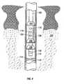
- FIG. 1there is shown a drilling rig 11 disposed atop a borehole 12.
- An MWD instrument 10commonly used to provide measurements while drilling, but which are not required for the present invention, is carried by a sub 14, typically a drill collar, incorporated into a drill string 18 and disposed within the borehole 12.
- a drill bit 22is located at the lower end of the drill string 18 and carves a borehole 12 through the earth formations 24, Drilling mud 26 is pumped from a storage reservoir pit 27 near the wellhead 28, down an axial passageway (not shown) through the drill string 18, out of apertures in the bit 22 and back to the surface through the annular region 16, usually referred to as the annulus.
- Metal surface casing 29is positioned in the borehole 12 above the drill bit 22 for maintaining the integrity of the upper portion of the borehole 12.
- the drill string 18is pulled out of the borehole, and the drill bit 22 removed from the end of the drill string.
- a string of steel casingis run into the well at least down to the formation which is believed to contain oil and/or gas.
- the cased boreholewill typically still contain some volume of drilling fluid.
- the drill string 18is then run back into the wellbore until its lower end is below the formation of interest.
- a spacer fluiddiscussed above as usually including various chemicals for cleaning the interior of the casing, is pumped down the interior of the drill string, theoretically causing the drilling fluid to be displaced and pumped toward the earth's surface through the annulus 16.
- the completion or workover fluidis then pumped down the interior of the drill string 18, displacing the spacer fluid, and causing the spacer fluid to be pumped towards the earth's surface, all as is conventional and well known in this art,
- Thiscan be problematic in that the three (3) fluids, i.e. the drilling fluid, the spacer fluid and the completion fluid often times tend to mix, rather than continue as three discrete, separated fluids.
- the mud pump 30is connected such that its output pumps mud (drilling fluid) into and along the annulus 16 and then into the lower end of the drill string 18, and ultimately back to the earth's surface, all of which is well recognized and understood by those skilled in the art of drilling oil and gas wells.
- the mud pump 30in the reverse circulation mode, has its output connected through a line 42 into the annulus 16.
- a packer 44is set below the open end 46 of the drill string 18 to isolate the portion of the wellbore above the packer from the portion of the wellbore below the packer.
- the interior of the drill string 18is connected through a fluid line 48 back to the mud tank 50,
- the fluid line 52connected into the mud tank 50, is connected to the fluid input of mud pump 30.
- steel casing 56is positioned in the wellbore, and the process begins for displacing the drilling fluid with completion fluid, typically a clear, heavy brine as above discussed.
- the casingcan be perforated by explosive charges, for example, with bullets or shaped charges, all of which are conventional and well known in this art, and the oil and/or gas in the producing zone, if any, can be produced through the perforations into the wellbore and pumped to the earth's surface through conventional means, for example, through production tubing.
- explosive chargesfor example, with bullets or shaped charges, all of which are conventional and well known in this art
- the oil and/or gas in the producing zoneif any, can be produced through the perforations into the wellbore and pumped to the earth's surface through conventional means, for example, through production tubing.
- the drilling fluid in mud tank 49is cleaned out and replaced by a spacer fluid, above discussed and usually containing chemical cleaning fluids. After the spacer is pumped in, the spacer fluid is cleaned out of the mud pit 49 and replaced with the completion fluid, which is then pumped in to displace the spacer fluid.
- a sub 80is incorporated into the drill string 18 in accordance with the present invention.
- the sub 80is actually a pair of subs 82 and 84 which together substitute for the drill collar 60 illustrated in FIG. 2 .
- Sub 82has a pair of conventional, elastomeric swab cups 86 and 88 having diameters chosen to enable the swabbing of the casing 56 illustrated in FIG. 2 .
- Sub 84has a pair of conventional casing scrapers 90 and 92 having diameters chosen to enable the cleaning of the interior wall of casing 56 illustrated in FIGS. 2 and 3 .
- the swab cups 86 and 88, as well as the casing scrapers 90 and 92,are well known in the art and thus require nothing more than a diagrammatic illustration and description.
- the upper sub 82(closer to the earth's surface in use) may have a male pin 94 for connection into the drill string 18, whereas the lower sub 84 may have a female lower end 96 for receiving any additional subs below the sub 84, or vice versa.
- the drill string 18 having the subs 82 and 84is prepared for running back into the borehole.
- the drilling fluid in mud pit 49has been replaced with completion fluid and is ready to be pumped into the annulus 16 immediately on top of the top surface 87 of swab cup 86.
- the completion fluidis pumped into the annulus 16 to maintain the annulus above the swab cups full of the completion fluid.
- drilling fluid in the boreholeis forced through the open end 96 of the lowermost sub, through a one-way check valve 100, and back towards the earth's surface through the interior fluid channel of the drill string.
- the check valve 100prevents the displaced fluid from coming back into the wellbore, Depending upon the volume of the displaced drilling fluid, the drilling fluid can either be pumped back into the mud pit 49 or into a second mud pit (not illustrated) to avoid mixing the returned drilling fluid and the completion fluid at the earth's surface.
- the casing scraper 90 and 92will remove most, if not all of the buildup on the casing wall which might otherwise destroy or lessen the efficiency of the elastomeric swab cups.
- the drill string 18(or production tubing if desired) can include a conventional perforation sub 100 such as illustrated in FIG. 2 , which sub 100 could include bullet guns or shaped charges, all of which is well know in the art as Tubing Conveyed Perforation.
- FIG. 4illustrates an alternative embodiment of the present invention in which normal circulation is used.
- the drill string (or other tubular) 102has a pair of swab cups 104 and 106, as well as a casing scraper 108,
- the drill string 102is illustrated as being positioned in an earth borehole 110 into which steel casing 112 has already been run in.
- a packer 114is run in as an option to isolate the portion of the borehole 110 above the packer from that portion of the borehole 110 below the packer.
- the packer 114can have a surface-controlled fluid bypass if desired to allow drilling fluid to be pumped below the packer as needed.
- the lower end of the drill string 102has a plug 116 to prevent the displacement fluid from being pumped out of the lower end of tubular 102 and thus prevents the mixing of the drilling fluid with the completion fluid.
- One or more fluid conduits 126are connected between swab cups 104 and to allow drilling fluid within the borehole 110 to bypass the swab cups as the drill string 102 is raised or lowered in the borehole.
- the interior of the drill string 102is filled with the completion fluid.
- the completion fluidalso exits the one or more orifices 116, 118 and 120 into the annulus 122 located between the swab cups 104 and 106.
- the drill string 102can be lowered or raised to cause the completion fluid to be adjacent the potential producing zone 124 to allow the desired operation to take place, i.e., perforation of the casing 112, workover, etc.
- the casing 112can be perforated from a perforation gun, or an array of shaped charges carried by the production tubing, all of which is conventional and well known in the art.
- the displacement fluidhas, for the most part, been described herein as being a completion fluid.
- the apparatus and methods described hereinare applicable to any downhole system in which one fluid is displacing another, and in which separation of the two fluids is desired.
- workover fluidsare being used on the formation of interest, it is fairly common to replace the drilling fluid, or whatever other fluid is in the wellbore, e.g. water or hydrocarbons produced from the formation, with such workover fluids.
- a hollow steel riser 200 extending from the earth's surface (not illustrated) or from an offshore platform (not illustrated) used in the drilling, completion, workover and/or production of oil and gas wellsis illustrated as having a blowout preventer 202 (BOP), which typically would be a conventional Ram BOP having one or more hydraulic lines 204 and 206, extending to the earth's surface or to an offshore platform, which are used to open and dose its rams.
- a pair of choke and kill lines 208 and 210also extend either to the earth's surface onto the offshore platform, as the case may be, and which allow fluid to be pumped into the interior of the riser at inlets 212 and 214, respectively.
- a steel tubular 216for example, a steel drill pipe, is illustrated as run into the interior of the riser 200 from the earth's surface or an offshore platform, and includes a one-way check valve 218 allowing fluid within the tubular 216 to be pumped down through the tubular 216 in the direction shown by arrow 219.
- the tubularcarries a scraper 220, for example, a steel brush for mechanically cleaning the interior surface of the riser 200, and can be spring-loaded, if desired, to maintain contact with the wall of the riser 200.
- a scraper 220for example, a steel brush for mechanically cleaning the interior surface of the riser 200, and can be spring-loaded, if desired, to maintain contact with the wall of the riser 200.
- the tubular 216carries one or more swab cups 222 and 224, preferably of the type which are activated by fluid pressure exerted on their lower surfaces 223 and 225, respectively, to engage the interior wall of the riser 200.
- the swab cups 222 and 224can be either the type of cups which can be activated, i.e. pressed against the interior wall of the riser, by pressure exerted against their lower surfaces, or by pressure exerted against their upper surfaces, vii, by the hydrostatic pressure of the mud column in the riser to be pumped out of the riser, or can be a combination of such swab cups.
- the tubular 216also carries a jetting unit 230 and bull plug 232 at its lower end to allow cleaning fluid to be pumped through the valve 218 and out through the many holes 231 in the jetting unit 230 into the interior of the riser 200.
- the tubular 216is raised enough to cause the jetting unit 230 and bull plug to come out of the open BOP 202.
- the rams of the BOPare then closed, preventing any fluid from being pumped below the BOP.
- the choke and kill linesare then activated, putting hydraulic pressure underneath the swab cups 222 and 224.
- the tubular 216is thus pumped out of the riser 200 as hydraulic pressure is maintained against the lower surfaces 223 and 225 of swap cups 222 and 224, respectively, preferably while mechanically lifting the tubular 216 from the earth's surface or an offshore platform.
- FIG. 6illustrates an alternative embodiment of the system illustrated in FIG.5 , in which the choke and kill lines 250 and 252 are located beneath the BOP 202 and the choke and kill lines 208 and 210 may or may not even be present.
- a plug 260for example, an inflatable packer, is run in and set within the riser 200 below the BOP 202, As soon as the tubular 216 has been lowered to the desired depth in the riser 200, the choke and kill lines 250 and 252 are activated, putting the hydraulic pressure on the lower surfaces 223 and 225 of swab cups 222 and 224, respectively. This causes tubular 216 to be pumped out of the riser 200 as with the embodiment of FIG., 5 , but without closing the rams in the BOP 202.
- a casing string 300having a lower section 310 of a given internal diameter and an upper section 320 of an internal diameter greater than said given diameter.
- a tool 330 according to the present inventionis run through the interior of the casing string by manipulating a tubular string 345 from the earth's surface, either by lowering or raising the string 345.
- the tool 330includes a conventional annular pressure relief valve 340, a conventional swivel joint 350, a first pair of swab cups 360 and 362, a second pair of swab cups 370 and 372, as well as a plurality of spring-loaded casing scrapers or brushes 380.
- the first pair of swab cups 360 and 362each have an external diameter large enough to swab the internal diameter of the casing section 320.
- the second pair of swab cups 370 and 372each have an external diameter large enough to swab the internal diameter of the reduced diameter casing section 310.
- the plurality of spring-loaded casing scrapers 380are in their expanded mode to scrape and clean the internal diameter of the casing section 320, but will compress to scrape and clean the internal diameter of the casing section 310, as the tool 330 is lowered into the casing section 310.
- FIG. 8illustrates the tool 330 being lowered into the reduced diameter casing section 310 and the compression of the spring-loaded casing scrapers 380 to fit within the reduced diameter casing section 310.
- FIG. 9illustrates the first, upper pair of swab cups 362 being sheared away from the tubular body or mandrel 332 of the tool 330 upon coming into contact with the upper end 334 of the reduced diameter casing section 310, and resting upon the upper end 334 as the tool 330 is lowered further into the casing section 310.
- FIG. 11illustrates but one example of how the swab cups 360 and 362 are sheared away from the tubular mandrel 332 of the tool 330.
- the swab cup 362has a sleeve 364, preferably manufactured from metal or hard plastic, sized to slide over the exterior surface of the mandrel 332.
- a plurality of shear pinsillustrated by the pair of shear pins 363 and 365, are used to hold the swab cup 362 secured in place on the mandrel 332.
- the shear pinsare selected to shear at pre-selected values, but should be selected to be of high enough value so as not to shear due to fluid pressure exerted upon the swab cups during the operation of the tool.
- the shear pinscould be selected to shear at 1500 psi and avoid shearing due to the fluid pressure.
- the casing scrapers 380which can be spring-loaded steel brushes if desired, do not clean out the debris properly, and an obstruction can exist in the casing. Such an obstruction could cause a premature shearing of one or more swab cups.
- a conventional devicecan be mounted on the tool 330 to protect the shearable swab cups, in the event of the "no-go" device encountering such an obstruction.
- the further lowering of the tool 330causes the shear pins 363 and 365 to shear, as well as the shear pins in swab cup 360 (not illustrated but identical to those used in swab cup 362), causing the swab cups 362 and 360 to rest upon the surface 334 illustrated in FIG. 9 .
- This processallows the smaller swab cups 370 and 372, and the spring-loaded scraper 380 to be further lowered into the smaller casing section 310.
- FIG. 10illustrates the tool 330 being moved up and out of the casing string. If it is desired to move fluid out of the casing, it should be appreciated that the large swab cups 360 and 362 merely rest upon the smaller swab cups 370 and 372, as illustrated in FIG, 10 , and as the tubular string 345 is pulled up, the swab cups 360 and 362 push the fluid in the casing all the way up in the casing string to the earth's surface.
- FIGS, 7-11show the use of a pair of large swab cups and a pair of smaller swab cups in only two sizes of casing
- the inventionis intended to also be used with three or more different sizes of casing, since the typical oil and gas well is cased progressively smaller with depth in the earth borehole,
- the inventioncontemplates the use of one, two, three or more swab cups of a given size, diameter, or combinations thereof.
Landscapes
- Engineering & Computer Science (AREA)
- Geology (AREA)
- Life Sciences & Earth Sciences (AREA)
- Mining & Mineral Resources (AREA)
- Geochemistry & Mineralogy (AREA)
- Environmental & Geological Engineering (AREA)
- General Life Sciences & Earth Sciences (AREA)
- Physics & Mathematics (AREA)
- Fluid Mechanics (AREA)
- Mechanical Engineering (AREA)
- Earth Drilling (AREA)
- Perforating, Stamping-Out Or Severing By Means Other Than Cutting (AREA)
- Cleaning In General (AREA)
- Cleaning By Liquid Or Steam (AREA)
- Excavating Of Shafts Or Tunnels (AREA)
- Drilling And Boring (AREA)
- Drilling And Exploitation, And Mining Machines And Methods (AREA)
- Solid-Sorbent Or Filter-Aiding Compositions (AREA)
- Branch Pipes, Bends, And The Like (AREA)
Abstract
Description
- The invention relates, generally, to new and improved methods and apparatus using mechanical separation between the drilling fluid and the displacement fluids, and specifically, to the use of swab cups to mechanically separate the drilling fluid from the displacement fluids, in combination with a casing scraper to remove debris from the inner wall of the casing or other tubular members, The method and apparatus can also be used to clean up downhole fluids, and can be used to wipe well casing and completion risers clean, even with varying internal diameters.
- It is well known in the art of the completion and/or the workover of oil and gas wells to displace the drilling fluid with a completion fluid or a workover fluid. A workover fluid will typically be either a surface cleaning fluid, such as an acid, to clean out the perforations in the casing, or a formation treating chemical which can be used with proppants to prop open the formation. The completion fluid will typically be a clear, heavy brine such as calcium chloride, calcium bromide or zinc bromide, or various combinations of such heavy brines. The density of such clear brines is generally selected and controlled to ensure that the hydrostatic head or pressure of the fluid in the wellbore will match the hydrostatic pressure of the column of drilling fluid being displaced.
- Displacement "spacers", as they are commonly named, are used between the drilling fluid and the completion fluid, and these are typically formulated from specific chemicals designed for the specific base drilling fluid being displaced, and will typically include weighted or unweighted barrier spacers, viscous barrier spacers, flocculating spacers, and casing cleaning chemicals, as desired.
- It is well known in this art that complete displacement of the drilling fluids is critical to the success of completion and/or workover operations. It is extremely important that the brines not be mixed with the drilling fluid itself.
- In the prior art, there are two principal displacement methods,viz., direct and indirect. The choice between direct and indirect has depended upon casing-tubing strengths, cement bond log results, and exposure of the formation of interest. If the cement bond logs and the casing strength data indicate that the casing would withstand a calculated pressure differential,i.e., that the casing would not rupture, and that the formation of interest is not exposed, the conventional technique has been that of indirect displacement.
- In a typical indirect displacement, large volumes of sea water are used to flush the drilling fluid out of the well. When applying the flushing method, however, it is very important that the pressure of the salt water flush not exceed the pressure which would burst the casing being flushed.
- Direct displacement of the drilling fluid, used by those in this art whenever there are pressure problems or the formation of interest is exposed, uses chemical agents and weighted fluids to clean the wellbore and to separate the drilling fluid from the workover/completion fluid. Because a constant hydrostatic pressure is maintained, pressure problems are eliminated. Direct displacement is normally used when (1) casing and tubulars cannot withstand the pressures associated with the indirect displacement procedure; (2) when the formation of interest is exposed; (3) if a source of flushing water, typically salt water, is not readily available; or (4) in the event of disposal and discharge restraints being imposed on the particular well or group of wells.
- A common element to both the direct and indirect displacement procedures is the use of barriers and cleaning chemicals ("spacers") for effective hole cleaning and separation between the drilling fluid and the completion/workover fluid. The primary purpose of a barrier spacer is to provide a complete separation between the drilling fluid and the completion/workover fluid. In such prior art systems, the spacer fluid must be compatible with both the drilling fluid and the workover/completion fluid.
- However, to the best of applicant's knowledge, the prior art has not had the ability to displace the drilling fluid with a workover/completion fluid without using a spacer fluid between the drilling fluid and the workover/completion fluid.
- It is also well known in this art to use casing scrapers to clean-off the interior wall of a downhole casing, but typically, cannot use the same tool in cleaning casing strings or other tubular members of varying diameters. The following prior art United States patents show various combinations of casing scrapers and/or swab cups, but none of such patents, taken alone or in combination, show or suggest the combination of the present invention.
US-A-2362198 : This shows a casing scraper (brush) in combination with swab cups 17 inFIG. 1 , and the flow of various fluids (water, circulation fluid or cement) through thehollow rod 10. This device is meant to vertically reciprocate to clean the interior of casing, but does not suggest using the swab cups as a mechanical separation of the drilling fluid and the completion fluid.US-A-2652120 : This shows acasing scraper 22 and a seal ring 23 (an inflatable packer instead of a swab cup) and a reciprocating rod 15 to create a suction which cleans out theperforations 12 in the casing (see Col. 3, lines 4868 concerning its operation). The patent does not suggest the concept of mechanical separation of the fluids.US-A-2687774 : This is related toUS-A-2652120 , discussed above, and is of no additional relevance.US-A-2825411 : This shows a swabbing device which includes a typical chemical cleaning process in conjunction with the reciprocating swabbing process. (See Col. 6, lines 1-11 for the chemical cleaning process.) There is no suggestion of mechanically separating the completion fluid from the drilling fluid.US-A-3637010 : This is of very little, if any, relevance, showing packers 66 and 68 (seeFIG. 2 ) in a gravel packing operation in horizontal wells.US-A-4838354 : This shows a casing scraper withblades 18 and a packer 76 supported by atubing string 12 having adrill bit 48 at its lower end, all within the casing 68. The production packer 76 is apparently anchored to the casing wall independently of the downward movement of thetubing string 12. This patent does not suggest the concept involving the mechanical separation of the fluids. In fact, as the pumped fluid exits the drill bit, the fluid returns back through theannulus 82 between thetubing string 12 and the inner tubular member 66 passing through the interior of the packer 76.US-A-4892145 : This showschevron packings 22 and 23, on opposite sides of a cavity "AC" (seeFIG. 2 ). Knife blade 34 functions as a scraper between thechevron packings 22 and 23. Once the chevron packings have isolated the perforations in the casing, fluid is pumped out ofopenings 27 in themandrel 11 to clean out the perforations.US-A-4921046 : This shows a cleanup tool for cleaning the interior of a casing string having apacker cup 18 for sealing the tool to the casing wall, and which pumps clean out fluid out through theport 84 into the casing below the packer cup. The debris is then picked up by the pumped fluid and pumped into the lower end of the mandrel 70 and pumped back to the earth's surface. This does not suggest a mechanical separation of the completion fluid and the drilling fluid.US-A-5076365 : This is the samedisclosure as US-A-4838354 , discussed above, and the same comments apply.US-A-5119874 : This well clean out system is used to pump sand and other debris out of the bottom of a producing well, but aside from using swab cups, has essentially no relevance to the present invention.US-A-4765405 : This document discloses an improved tool for washing the perforations in an oil or gas well bore casing. The tool includes a tubular mandrel having orifices, between pairs of pressure sealing packer cups, for discharging a cleaning fluid into the area between the tool and the casing.US-A-4893684 is considered to be the closest prior art: This document discloses a well bore elastomeric annulus wiper plug having a central body and inner and outer elastomeric ribs generally in the shape of truncated cones. In operation at a producing well, or after casing has been set at a drilling well, the wiper plug is inserted into the well bore by placing the wiper plug around an inner tubular member at the surface. A new drilling fluid is pumped into the well on top of the wiper plug in a reverse-circulation manner until the wiper plug reaches the effective depth of the well. The wiper plug will proceed downwardly through the annular space between the casing and the drill string or tubing. Upon reaching the bottom of the drill string or tubing the wiper plug would settle to the bottom of the well, be retrieved, or be drilled out, or left in place.- It is therefore the primary object of the present invention to provide new and improved methods and apparatus for displacing the drilling fluid in a wellbore with one or more completion and/or workover fluids.
- It is yet another object of the present invention to provide a new and improved cleaning and/or wiping of the interior of drilling and completion risers.
- It is another object of the present invention to provide new and improved separation of the drilling fluid from one or more completion and/or workover fluids.
- It is another object of the invention to provide new and improved methods and apparatus for cleaning the interior surfaces of easing strings or other tubular members having progressively smaller internal diameters as a function of depth of the casing in earth boreholes.
- The present invention is directed, generally, to methods and apparatus which employ a plurality of swab cups integrally located within a string of tubular pipe, positioned within a cased earth borehole, or within a drilling or completion riser, and having drilling fluid located on one side of the plurality of swab cups and the workover fluid or the completion fluid located on the other side of the plurality of swab cups, resulting in a mechanical separation of the drilling fluid and the workover/completion fluid.
- In one mode of the invention, the tubular is lowered into the cased wellbore, typically loaded with drilling fluid, with the completion/workover fluid being pumped behind the plurality of swab cups. This action forces the drilling fluid to be pumped from the wellbore through the interior of the tubular back near or to the earth's surface.
- As an additional feature of the invention, a mechanical scraper is run below the swab cups to help clean the interior of the well casing and to prevent or lessen any damage to the swab cups.
- In an alternative embodiment of the invention, the displacement fluid is located between a pair of swab cups and the drilling fluid located in the borehole annulus other than between the pair of swab cups.
- Alternatively, the combination swab cup and scraper assembly is run to the desired depth in the cased wellbore, or riser, and then pulled out of the hole, bringing the drilling fluid or other fluid to be displaced towards the earth's surface by taking returns up the annulus, with that portion of the cased borehole, or the riser, below the assembly being back-filled with the displacement fluid.
- As a special feature of the invention, the tool includes swab cups of varying external diameters, in which at least one or more of them are sheared upon meeting decreased diameter tubulars, allowing the tool to be used in varying diameter tubulars.
FIG. 1 is an elevated, side pictorial view, partly in cross-section, illustrating a drilling rig using normal circulation of the drilling fluid through the drillstring;FIG. 2 is an elevated, side, diagrammatic view of a rig site using reverse circulation of the drilling fluid through the drillstring;FIG. 3 is an elevated, side, diagrammatic view of the combined well swab and casing scraper used in accordance with the present invention;FIG. 4 is an elevated, side, diagrammatic view of the combined well swab and easing scraper used in accordance with an alternative embodiment of the invention;FIG. 5 is an elevated, side, diagrammatic view of the combined swab cup and scraper used in accordance with the invention to clean the interior wall of a drilling or completion riser;FIG. 6 is an elevated, side, diagrammatic view of the combined swab cup and scraper used in accordance with an alternative embodiment of the invention to clean the interior wall of a drilling or completion riser;FIG. 7 is an elevated, side, pictorial view, partly in cross-section, of a tool according to the present invention, having spring-loaded casing scrapers and a first pair of swab cups of a given external diameter and a second pair of swab cups of a diameter greater than said given diameter;FIG. 8 is an elevated, side, pictorial view of the tool ofFIG, 7 as the pair of swab cups of a given diameter are first entering a reduced diameter portion of a easing string;FIG. 9 is an elevated, side, pictorial view of the tool ofFIG, 7 illustrating the sheared swab cups of the greater diameter resting on top of the first section of reduced diameter easing; andFIG. 10 is an elevated, side, pictorial view of the tool ofFIG. 7 illustrating the tool being pulled out of the casing string.- Referring now specifically to the drawings, and first to
FIG. 1 , there is shown adrilling rig 11 disposed atop aborehole 12. AnMWD instrument 10, commonly used to provide measurements while drilling, but which are not required for the present invention, is carried by asub 14, typically a drill collar, incorporated into adrill string 18 and disposed within theborehole 12. Adrill bit 22 is located at the lower end of thedrill string 18 and carves a borehole 12 through theearth formations 24,Drilling mud 26 is pumped from astorage reservoir pit 27 near thewellhead 28, down an axial passageway (not shown) through thedrill string 18, out of apertures in thebit 22 and back to the surface through theannular region 16, usually referred to as the annulus. Metal surface casing 29 is positioned in theborehole 12 above thedrill bit 22 for maintaining the integrity of the upper portion of theborehole 12. - In the operation of the apparatus illustrated in
FIG.1 , in which the drilling fluid is pumped down through the interior of thedrill string 18, out through thebit 22, and back to the earth's surface via theannulus 16, there is thus described socalled "normal circulation". - In a method commonly used in the prior art, still referring to
FIG. 1 , thedrill string 18 is pulled out of the borehole, and thedrill bit 22 removed from the end of the drill string. A string of steel casing is run into the well at least down to the formation which is believed to contain oil and/or gas. At this point in time, the cased borehole will typically still contain some volume of drilling fluid. Thedrill string 18 is then run back into the wellbore until its lower end is below the formation of interest. A spacer fluid, discussed above as usually including various chemicals for cleaning the interior of the casing, is pumped down the interior of the drill string, theoretically causing the drilling fluid to be displaced and pumped toward the earth's surface through theannulus 16. The completion or workover fluid is then pumped down the interior of thedrill string 18, displacing the spacer fluid, and causing the spacer fluid to be pumped towards the earth's surface, all as is conventional and well known in this art, This, of course, can be problematic in that the three (3) fluids,i.e. the drilling fluid, the spacer fluid and the completion fluid often times tend to mix, rather than continue as three discrete, separated fluids. - In the "reverse circulation" mode of operation, illustrated diagrammatically in
FIG. 2 , themud pump 30 is connected such that its output pumps mud (drilling fluid) into and along theannulus 16 and then into the lower end of thedrill string 18, and ultimately back to the earth's surface, all of which is well recognized and understood by those skilled in the art of drilling oil and gas wells. - In
FIG. 2 , in the reverse circulation mode, themud pump 30 has its output connected through aline 42 into theannulus 16. If desired, apacker 44 is set below theopen end 46 of thedrill string 18 to isolate the portion of the wellbore above the packer from the portion of the wellbore below the packer. The interior of thedrill string 18 is connected through afluid line 48 back to themud tank 50, Thefluid line 52, connected into themud tank 50, is connected to the fluid input ofmud pump 30. - It should be appreciated that most drilling operations use the normal circulation system embodied in
FIG. 1 , although some wells have been drilled using the reverse circulation mode of FIO. 2, in which the drilling fluid is pumped down theannulus 16, through the drill bit (not illustrated inFIG. 2 ) and up through the interior of thedrill string 18 back to the mud pit 49 containing thedrilling fluid 50. - Referring further to
FIG. 2 , once it has been determined from well logs, earth core samples and the like, that a potential oil and/or gas zone has been identified at a given depth in the formation, for example, thezone 54,steel casing 56 is positioned in the wellbore, and the process begins for displacing the drilling fluid with completion fluid, typically a clear, heavy brine as above discussed. Once the interior of the casing string has been cleaned, and the completion fluid is in place, the casing can be perforated by explosive charges, for example, with bullets or shaped charges, all of which are conventional and well known in this art, and the oil and/or gas in the producing zone, if any, can be produced through the perforations into the wellbore and pumped to the earth's surface through conventional means, for example, through production tubing. - In providing the displacement fluids, if done in the conventional mode, the drilling fluid in mud tank 49 is cleaned out and replaced by a spacer fluid, above discussed and usually containing chemical cleaning fluids. After the spacer is pumped in, the spacer fluid is cleaned out of the mud pit 49 and replaced with the completion fluid, which is then pumped in to displace the spacer fluid.
- Referring now to
FIG, 3 , a sub 80 is incorporated into thedrill string 18 in accordance with the present invention. The sub 80 is actually a pair ofsubs drill collar 60 illustrated inFIG. 2 .Sub 82 has a pair of conventional, elastomeric swab cups 86 and 88 having diameters chosen to enable the swabbing of thecasing 56 illustrated inFIG. 2 .Sub 84 has a pair ofconventional casing scrapers FIGS. 2 and3 . The swab cups 86 and 88, as well as thecasing scrapers male pin 94 for connection into thedrill string 18, whereas thelower sub 84 may have a femalelower end 96 for receiving any additional subs below thesub 84, or vice versa.
In the operation of the system in accord withFIGS, 2 and3 , after thepotential producing zone 54 has been identified with well logs, core samples, etc., and thesteel casing 56 set in the borehole, thedrill string 18 having thesubs annulus 16 immediately on top of thetop surface 87 ofswab cup 86. As thedrill string 18 is lowered into the borehole, the completion fluid is pumped into theannulus 16 to maintain the annulus above the swab cups full of the completion fluid. As the swab cups 86 and 88 move down in the cased borehole, drilling fluid in the borehole is forced through theopen end 96 of the lowermost sub, through a one-way check valve 100, and back towards the earth's surface through the interior fluid channel of the drill string. Thecheck valve 100 prevents the displaced fluid from coming back into the wellbore, Depending upon the volume of the displaced drilling fluid, the drilling fluid can either be pumped back into the mud pit 49 or into a second mud pit (not illustrated) to avoid mixing the returned drilling fluid and the completion fluid at the earth's surface. - By having the
casing scrapers - Once the swab cups have been lowered below the portion of the
casing 56 covering the plannedproduction zone 54, all of the drilling fluid will have been displaced from the borehole opposite theproduction zone 54, as by pushing or pulling the fluid being displaced, and the completion, workover or other desired operation through thecasing 56 opposite thezone 54 can be accomplished. If the task involves completion, the drill string 18 (or production tubing if desired) can include aconventional perforation sub 100 such as illustrated inFIG. 2 , whichsub 100 could include bullet guns or shaped charges, all of which is well know in the art as Tubing Conveyed Perforation. - There has thus been illustrated and described methods and apparatus which provide a mechanical separation of the drilling fluid being displaced, from the displacement fluid, typically a completion or workover fluid, thus providing an improvement over the problematic task of pumping three dissimilar fluids through a common fluid channel while attempting to maintain a reasonable separation of the three fluids.
- Although the preferred embodiment contemplates using reverse circulation because of being easier to mechanically separate the drilling fluid from the completion or workover fluid, obvious modifications to the preferred embodiment will be apparent to those skilled in the art.
- For example,
FIG. 4 illustrates an alternative embodiment of the present invention in which normal circulation is used. The drill string (or other tubular) 102 has a pair of swab cups 104 and 106, as well as acasing scraper 108, Thedrill string 102 is illustrated as being positioned in anearth borehole 110 into whichsteel casing 112 has already been run in. Apacker 114 is run in as an option to isolate the portion of theborehole 110 above the packer from that portion of theborehole 110 below the packer. Thepacker 114 can have a surface-controlled fluid bypass if desired to allow drilling fluid to be pumped below the packer as needed. The lower end of thedrill string 102 has aplug 116 to prevent the displacement fluid from being pumped out of the lower end oftubular 102 and thus prevents the mixing of the drilling fluid with the completion fluid. - Located intermediate the
swab cubs orifice 116, but preferably a plurality oforifices fluid conduits 126 are connected between swab cups 104 and to allow drilling fluid within theborehole 110 to bypass the swab cups as thedrill string 102 is raised or lowered in the borehole. - In the operation of the apparatus illustrated in
FIG. 4 , as thedrill string 102 is to be lowered into thewellbore 110 from the earth's surface, the interior of thedrill string 102 is filled with the completion fluid. The completion fluid also exits the one ormore orifices drill string 102 can be lowered or raised to cause the completion fluid to be adjacent thepotential producing zone 124 to allow the desired operation to take place, i.e., perforation of thecasing 112, workover, etc. If the tubular 102 is production tubing, thecasing 112 can be perforated from a perforation gun, or an array of shaped charges carried by the production tubing, all of which is conventional and well known in the art. For case of presentation, the displacement fluid has, for the most part, been described herein as being a completion fluid. However, the apparatus and methods described herein are applicable to any downhole system in which one fluid is displacing another, and in which separation of the two fluids is desired. For example, when workover fluids are being used on the formation of interest, it is fairly common to replace the drilling fluid, or whatever other fluid is in the wellbore, e.g. water or hydrocarbons produced from the formation, with such workover fluids. Workover fluids are well known in the art, for example, as described inComposition and Properties of Oil Well Drilling Fluids, Fourth Edition, by George R. Gray et al., at pages 476- 525. Another fluid which may be used to displace the fluid in the borehole is the so-called packer fluid, also discussed in that same reference on pages 476-525. - In
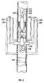
FIG. 5 , ahollow steel riser 200 extending from the earth's surface (not illustrated) or from an offshore platform (not illustrated) used in the drilling, completion, workover and/or production of oil and gas wells, is illustrated as having a blowout preventer 202 (BOP), which typically would be a conventional Ram BOP having one or morehydraulic lines lines 208 and 210 also extend either to the earth's surface onto the offshore platform, as the case may be, and which allow fluid to be pumped into the interior of the riser atinlets steel tubular 216, for example, a steel drill pipe, is illustrated as run into the interior of theriser 200 from the earth's surface or an offshore platform, and includes a one-way check valve 218 allowing fluid within the tubular 216 to be pumped down through the tubular 216 in the direction shown byarrow 219. - The tubular carries a scraper 220, for example, a steel brush for mechanically cleaning the interior surface of the
riser 200, and can be spring-loaded, if desired, to maintain contact with the wall of theriser 200. - The tubular 216 carries one or more swab cups 222 and 224, preferably of the type which are activated by fluid pressure exerted on their
lower surfaces riser 200. The swab cups 222 and 224 can be either the type of cups which can be activated, i.e. pressed against the interior wall of the riser, by pressure exerted against their lower surfaces, or by pressure exerted against their upper surfaces, vii, by the hydrostatic pressure of the mud column in the riser to be pumped out of the riser, or can be a combination of such swab cups. The tubular 216 also carries ajetting unit 230 andbull plug 232 at its lower end to allow cleaning fluid to be pumped through thevalve 218 and out through themany holes 231 in thejetting unit 230 into the interior of theriser 200. - In the operation of the embodiment of
FIG. 5 , the tubular 216 is raised enough to cause thejetting unit 230 and bull plug to come out of theopen BOP 202. The rams of the BOP are then closed, preventing any fluid from being pumped below the BOP. The choke and kill lines are then activated, putting hydraulic pressure underneath the swab cups 222 and 224. The tubular 216 is thus pumped out of theriser 200 as hydraulic pressure is maintained against thelower surfaces swap cups FIG. 6 illustrates an alternative embodiment of the system illustrated inFIG.5 , in which the choke and killlines BOP 202 and the choke and killlines 208 and 210 may or may not even be present.- A
plug 260, for example, an inflatable packer, is run in and set within theriser 200 below theBOP 202, As soon as the tubular 216 has been lowered to the desired depth in theriser 200, the choke and killlines lower surfaces riser 200 as with the embodiment ofFIG., 5 , but without closing the rams in theBOP 202. - Moreover, whether using the embodiments of
FIG. 5 orFIG. 6 , one can practice the invention without using the choke and kill lines, merely by either closing the BOP or by setting the plug, and pumping fluid down through the tubular, creating hydraulic pressure against the bottom surfaces of the swab cups. - This is not preferred, however, because this causes the tubular to be pulled while fluid is being pumped through it, sometimes referred to as pulling a "wet string". Those skilled in this art know, however, that by using a "mud bucket" (not illustrated), the wet string problem can be essentially circumvented.
- Referring now to HG 7, there is illustrated a
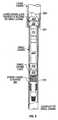
casing string 300 having alower section 310 of a given internal diameter and anupper section 320 of an internal diameter greater than said given diameter. Atool 330 according to the present invention is run through the interior of the casing string by manipulating atubular string 345 from the earth's surface, either by lowering or raising thestring 345. - The
tool 330 includes a conventional annularpressure relief valve 340, a conventional swivel joint 350, a first pair of swab cups 360 and 362, a second pair of swab cups 370 and 372, as well as a plurality of spring-loaded casing scrapers or brushes 380. - The first pair of swab cups 360 and 362 each have an external diameter large enough to swab the internal diameter of the
casing section 320. The second pair of swab cups 370 and 372 each have an external diameter large enough to swab the internal diameter of the reduceddiameter casing section 310. The plurality of spring-loadedcasing scrapers 380 are in their expanded mode to scrape and clean the internal diameter of thecasing section 320, but will compress to scrape and clean the internal diameter of thecasing section 310, as thetool 330 is lowered into thecasing section 310. FIG. 8 illustrates thetool 330 being lowered into the reduceddiameter casing section 310 and the compression of the spring-loadedcasing scrapers 380 to fit within the reduceddiameter casing section 310.FIG. 9 illustrates the first, upper pair of swab cups 362 being sheared away from the tubular body ormandrel 332 of thetool 330 upon coming into contact with theupper end 334 of the reduceddiameter casing section 310, and resting upon theupper end 334 as thetool 330 is lowered further into thecasing section 310.FIG. 11 illustrates but one example of how the swab cups 360 and 362 are sheared away from thetubular mandrel 332 of thetool 330. Theswab cup 362 has asleeve 364, preferably manufactured from metal or hard plastic, sized to slide over the exterior surface of themandrel 332. A plurality of shear pins, illustrated by the pair of shear pins 363 and 365, are used to hold theswab cup 362 secured in place on themandrel 332. The shear pins are selected to shear at pre-selected values, but should be selected to be of high enough value so as not to shear due to fluid pressure exerted upon the swab cups during the operation of the tool. For example, without limiting the intended use, if theswab cup 362 is expected to be exposed to 1000 psi fluid pressure, the shear pins could be selected to shear at 1500 psi and avoid shearing due to the fluid pressure. Moreover, there may be times in the operation of theapparatus 330 such that thecasing scrapers 380, which can be spring-loaded steel brushes if desired, do not clean out the debris properly, and an obstruction can exist in the casing. Such an obstruction could cause a premature shearing of one or more swab cups. A conventional device, commonly referred to as a 'no-go' device, can be mounted on thetool 330 to protect the shearable swab cups, in the event of the "no-go" device encountering such an obstruction. In the operation of the embodiment ofFIG. 11 , as thetool 330 is lowered in the casing string until theswab cup 362 comes into contact with thesurface 334, the further lowering of thetool 330 causes the shear pins 363 and 365 to shear, as well as the shear pins in swab cup 360 (not illustrated but identical to those used in swab cup 362), causing the swab cups 362 and 360 to rest upon thesurface 334 illustrated inFIG. 9 . This process allows the smaller swab cups 370 and 372, and the spring-loadedscraper 380 to be further lowered into thesmaller casing section 310.- All of the operations described above with respect to
FIGS. 1-6 can also be done with the tools illustrated and described inFIGS. 7-11 . FIG. 10 illustrates thetool 330 being moved up and out of the casing string. If it is desired to move fluid out of the casing, it should be appreciated that thelarge swab cups FIG, 10 , and as thetubular string 345 is pulled up, the swab cups 360 and 362 push the fluid in the casing all the way up in the casing string to the earth's surface.- While
FIGS, 7-11 show the use of a pair of large swab cups and a pair of smaller swab cups in only two sizes of casing, the invention is intended to also be used with three or more different sizes of casing, since the typical oil and gas well is cased progressively smaller with depth in the earth borehole, Although not preferred, the invention contemplates the use of one, two, three or more swab cups of a given size, diameter, or combinations thereof.
Claims (4)
- A method for displacing a first fluid (26) in a pre-selected zone of a cased earth borehole (12, 110, 200, 300) with a second fluid, comprising:running a string of tubular pipe (18, 102, 216, 345) into said cased earth borehole (12, 110, 200, 300), thereby forming an annulus (16, 122) between said tubular string of pipe (18, 102, 216, 345) and the casing string (26, 56, 112) in said cased earth borehole (12, 110, 200, 300); andpumping from the earth's surface said second fluid into the annulus (16, 122) within said borehole (12, 110, 200, 300) surrounding said string of tubular pipe (18, 102, 216, 345);characterized in that:said string (18, 102, 216, 345) comprises first and second swab cups (86, 88, 104, 106, 222, 224, 360, 362, 370, 372) mounted on a sub (14, 80, 82) incorporated into said borehole (12, 110, 200, 300) surrounding said string of tubular pipe (18, 102, 216, 345);said second fluid is pumped into the annulus (16, 122) above said first and second swab cups (86, 88, 104, 106, 222, 224, 360, 362, 370, 372); andthe method further comprises lowering said string of tubular pipe (18, 102, 216, 345) in said earth borehole (12, 110, 200, 300) while continuing to pump said second fluid into said annulus (16, 122) from the earth's surface, thereby causing said first fluid (26) in said earth borehole (12, 110, 200, 300) to be pumped through the interior of said string of tubular pipe (18, 102, 216, 345) towards the earth's surface, until said first and second swab cups (86, 88, 104, 106, 222, 224, 360, 362, 370, 372) have travelled past the pre-selected zone (24, 54, 124) of said cased earth borehole (12, 110, 200, 300).
- The method according to Claim 1, including in addition thereto, the step of scraping the casing (26, 56, 112) ahead of said swab cups (86, 88, 104, 106, 222, 224, 360, 362, 370, 372) swabbing such casing (26, 56, 112).
- The method according to Claim 1, wherein said first fluid (26) is a drilling fluid and said second fluid is a completion fluid selected from the class of calcium chloride, calcium bromide, zinc bromide or mixtures thereof.
- The method according to Claim 1, wherein said second fluid is a workover fluid.
Applications Claiming Priority (2)
| Application Number | Priority Date | Filing Date | Title |
|---|---|---|---|
| US09/329,544US6371207B1 (en) | 1999-06-10 | 1999-06-10 | Method and apparatus for displacing drilling fluids with completion and workover fluids, and for cleaning tubular members |
| EP00938252AEP1208285B1 (en) | 1999-06-10 | 2000-06-09 | Method and apparatus for displacing drilling fluids with completion and workover fluids, and for cleaning tubular members |
Related Parent Applications (2)
| Application Number | Title | Priority Date | Filing Date |
|---|---|---|---|
| EP00938252.4Division | 2000-06-09 | ||
| EP00938252ADivisionEP1208285B1 (en) | 1999-06-10 | 2000-06-09 | Method and apparatus for displacing drilling fluids with completion and workover fluids, and for cleaning tubular members |
Publications (3)
| Publication Number | Publication Date |
|---|---|
| EP1911927A2 EP1911927A2 (en) | 2008-04-16 |
| EP1911927A3 EP1911927A3 (en) | 2009-09-02 |
| EP1911927B1true EP1911927B1 (en) | 2011-03-23 |
Family
ID=23285901
Family Applications (2)
| Application Number | Title | Priority Date | Filing Date |
|---|---|---|---|
| EP00938252AExpired - LifetimeEP1208285B1 (en) | 1999-06-10 | 2000-06-09 | Method and apparatus for displacing drilling fluids with completion and workover fluids, and for cleaning tubular members |
| EP07120932AExpired - LifetimeEP1911927B1 (en) | 1999-06-10 | 2000-06-09 | Method and apparatus for displacing drilling fluids with completion and workover fluids |
Family Applications Before (1)
| Application Number | Title | Priority Date | Filing Date |
|---|---|---|---|
| EP00938252AExpired - LifetimeEP1208285B1 (en) | 1999-06-10 | 2000-06-09 | Method and apparatus for displacing drilling fluids with completion and workover fluids, and for cleaning tubular members |
Country Status (10)
| Country | Link |
|---|---|
| US (2) | US6371207B1 (en) |
| EP (2) | EP1208285B1 (en) |
| AT (2) | ATE394578T1 (en) |
| AU (1) | AU5332000A (en) |
| BR (1) | BR0011453B1 (en) |
| CA (1) | CA2374709C (en) |
| DE (2) | DE60038804D1 (en) |
| DK (2) | DK1208285T3 (en) |
| NO (1) | NO321871B1 (en) |
| WO (1) | WO2000077339A1 (en) |
Families Citing this family (60)
| Publication number | Priority date | Publication date | Assignee | Title |
|---|---|---|---|---|
| GB0201106D0 (en)* | 2002-01-18 | 2002-03-06 | Sps Afos Group Ltd | Disengageable downhole tool |
| GB0203386D0 (en)* | 2002-02-13 | 2002-03-27 | Sps Afos Group Ltd | Wellhead seal unit |
| US7950450B2 (en)* | 2002-08-16 | 2011-05-31 | Weatherford/Lamb, Inc. | Apparatus and methods of cleaning and refinishing tubulars |
| US6957698B2 (en)* | 2002-09-20 | 2005-10-25 | Baker Hughes Incorporated | Downhole activatable annular seal assembly |
| US6883605B2 (en)* | 2002-11-27 | 2005-04-26 | Offshore Energy Services, Inc. | Wellbore cleanout tool and method |
| EP1570154A4 (en)* | 2002-12-12 | 2006-05-03 | Albert August Mullins | Well bore cleaning and tubular circulating and flow-back apparatus |
| RU2249109C1 (en)* | 2003-08-18 | 2005-03-27 | Федин Алексей Константинович | Device for delivering well devices to pit-face in operating wells |
| US20070149076A1 (en)* | 2003-09-11 | 2007-06-28 | Dynatex | Cut-resistant composite |
| EA009708B1 (en)* | 2004-07-15 | 2008-02-28 | 2К Тек Ас | Apparatus for wiping the interior of pipes |
| US7290612B2 (en) | 2004-12-16 | 2007-11-06 | Halliburton Energy Services, Inc. | Apparatus and method for reverse circulation cementing a casing in an open-hole wellbore |
| US7290611B2 (en)* | 2004-07-22 | 2007-11-06 | Halliburton Energy Services, Inc. | Methods and systems for cementing wells that lack surface casing |
| US7252147B2 (en)* | 2004-07-22 | 2007-08-07 | Halliburton Energy Services, Inc. | Cementing methods and systems for initiating fluid flow with reduced pumping pressure |
| US7322412B2 (en)* | 2004-08-30 | 2008-01-29 | Halliburton Energy Services, Inc. | Casing shoes and methods of reverse-circulation cementing of casing |
| US7303008B2 (en)* | 2004-10-26 | 2007-12-04 | Halliburton Energy Services, Inc. | Methods and systems for reverse-circulation cementing in subterranean formations |
| US7303014B2 (en)* | 2004-10-26 | 2007-12-04 | Halliburton Energy Services, Inc. | Casing strings and methods of using such strings in subterranean cementing operations |
| US7284608B2 (en)* | 2004-10-26 | 2007-10-23 | Halliburton Energy Services, Inc. | Casing strings and methods of using such strings in subterranean cementing operations |
| US7270183B2 (en) | 2004-11-16 | 2007-09-18 | Halliburton Energy Services, Inc. | Cementing methods using compressible cement compositions |
| GB0513645D0 (en)* | 2005-07-02 | 2005-08-10 | Specialised Petroleum Serv Ltd | Wellbore cleaning method and apparatus |
| NO325898B1 (en)* | 2005-09-15 | 2008-08-11 | M I Swaco Norge As | Separating device |
| US7357181B2 (en)* | 2005-09-20 | 2008-04-15 | Halliburton Energy Services, Inc. | Apparatus for autofill deactivation of float equipment and method of reverse cementing |
| US20070089678A1 (en)* | 2005-10-21 | 2007-04-26 | Petstages, Inc. | Pet feeding apparatus having adjustable elevation |
| US7533729B2 (en)* | 2005-11-01 | 2009-05-19 | Halliburton Energy Services, Inc. | Reverse cementing float equipment |
| US7392840B2 (en)* | 2005-12-20 | 2008-07-01 | Halliburton Energy Services, Inc. | Method and means to seal the casing-by-casing annulus at the surface for reverse circulation cement jobs |
| JP4410195B2 (en)* | 2006-01-06 | 2010-02-03 | 株式会社東芝 | Semiconductor device and manufacturing method thereof |
| US7597146B2 (en)* | 2006-10-06 | 2009-10-06 | Halliburton Energy Services, Inc. | Methods and apparatus for completion of well bores |
| WO2008073343A1 (en)* | 2006-12-08 | 2008-06-19 | Wise Well Intervention Services, Inc. | Device and method for cleaning wells |
| EP2097613B1 (en)* | 2006-12-12 | 2018-05-02 | Halliburton Energy Services, Inc. | Improved downhole scraping and/or brushing tool and related methods |
| US7533728B2 (en) | 2007-01-04 | 2009-05-19 | Halliburton Energy Services, Inc. | Ball operated back pressure valve |
| US20080185150A1 (en)* | 2007-02-05 | 2008-08-07 | Irvine Cardno Brown | Apparatus and Method for Cleaning a Well |
| US20080196889A1 (en)* | 2007-02-15 | 2008-08-21 | Daniel Bour | Reverse Circulation Cementing Valve |
| US7614451B2 (en) | 2007-02-16 | 2009-11-10 | Halliburton Energy Services, Inc. | Method for constructing and treating subterranean formations |
| US7770648B2 (en)* | 2007-03-16 | 2010-08-10 | Baker Hughes Incorporated | Completion method for well cleanup and zone isolation |
| US7757757B1 (en)* | 2007-04-02 | 2010-07-20 | The United States Of America As Represented By The Secretary Of The Interior | In-well baffle apparatus and method |
| AU2008275243B2 (en)* | 2007-07-06 | 2015-03-19 | Halliburton Energy Services, Inc. | Multi-purpose well servicing apparatus |
| US7654324B2 (en)* | 2007-07-16 | 2010-02-02 | Halliburton Energy Services, Inc. | Reverse-circulation cementing of surface casing |
| US20090107676A1 (en)* | 2007-10-26 | 2009-04-30 | Saunders James P | Methods of Cementing in Subterranean Formations |
| US20090120633A1 (en)* | 2007-11-13 | 2009-05-14 | Earl Webb | Method for Stimulating a Well Using Fluid Pressure Waves |
| US20110168383A1 (en)* | 2010-01-09 | 2011-07-14 | Baker Hughes Incorporated | Cleaning Device |
| US8863836B2 (en)* | 2010-04-06 | 2014-10-21 | Chevron U.S.A. Inc. | Systems and methods for logging cased wellbores |
| US8356377B2 (en)* | 2010-05-11 | 2013-01-22 | Full Flow Technologies, Llc | Reinforced cup for use with a pig or other downhole tool |
| US8469116B2 (en)* | 2010-07-30 | 2013-06-25 | National Oilwell Varco, L.P. | Control system for mud cleaning apparatus |
| CN101899963A (en)* | 2010-08-17 | 2010-12-01 | 中国石油集团川庆钻探工程有限公司长庆井下技术作业公司 | Bidirectional plastic cup-type sand filtering swab and sand blockage-preventing method |
| US9255458B2 (en) | 2011-08-29 | 2016-02-09 | Foster Wheeler Usa Corporation | Method and system for sealing and handling pipe |
| US9534479B2 (en) | 2011-08-29 | 2017-01-03 | Amec Foster Wheeler Usa Corporation | Method and system for recovering, and displacing fluid from, a pipe |
| GB2502555A (en)* | 2012-05-30 | 2013-12-04 | M I Drilling Fluids Uk Ltd | Riser displacement and cleaning tool assembly |
| US9284795B2 (en)* | 2012-08-28 | 2016-03-15 | Halliburton Energy Services, Inc. | Riser displacement and cleaning systems and methods of use |
| AU2012397857B2 (en)* | 2012-12-28 | 2016-12-15 | Halliburton Energy Services Inc. | BHA surge relief system |
| US10539698B2 (en)* | 2014-06-18 | 2020-01-21 | Schlumberger Technology Corporation | Determining a quantitative bond using signal attenuation |
| EP3183413A4 (en)* | 2014-08-19 | 2017-08-02 | Aarbakke Innovation A.S. | Battery operated autonomous scale removal system for wells |
| US9765603B2 (en) | 2014-11-26 | 2017-09-19 | General Electric Company | Gas lift valve assemblies and methods of assembling same |
| US9689241B2 (en) | 2014-11-26 | 2017-06-27 | General Electric Company | Gas lift valve assemblies having fluid flow barrier and methods of assembling same |
| CN104632130A (en)* | 2014-12-03 | 2015-05-20 | 中国庆华能源集团有限公司 | Workover well completion process |
| CN104568625B (en)* | 2015-01-05 | 2017-04-12 | 中国石油大学(北京) | Crude oil pipeline ball passing and wax removal simulation experiment device and experiment method |
| CA3083134A1 (en)* | 2017-11-21 | 2019-05-31 | Peter Knight | Subterranean well sealing injector |
| CN110130845B (en)* | 2018-02-08 | 2024-03-26 | 中国石油天然气股份有限公司 | Oil well cleaning and conducting device |
| US10941649B2 (en)* | 2018-04-19 | 2021-03-09 | Saudi Arabian Oil Company | Tool for testing within a wellbore |
| US20190360310A1 (en)* | 2018-05-25 | 2019-11-28 | National Oilwell Varco, L.P. | Downhole Trimming Tool |
| WO2021033013A1 (en)* | 2019-08-22 | 2021-02-25 | Abu Dhabi National Oil Company | Through bop lubrication system |
| CN110593815B (en)* | 2019-09-12 | 2022-06-03 | 中国石油天然气股份有限公司 | High-salinity gas well underground descaling method |
| CN110617063B (en)* | 2019-11-10 | 2024-01-05 | 宝鸡市凯顺海陆装备科技有限公司 | Deep well sleeve outer annular space two-stage monitoring sampler and monitoring method thereof |
Family Cites Families (25)
| Publication number | Priority date | Publication date | Assignee | Title |
|---|---|---|---|---|
| US2214121A (en)* | 1938-04-08 | 1940-09-10 | William B Collins | Tool for handling fluids in wells |
| US2362198A (en)* | 1941-04-18 | 1944-11-07 | Clair J Gibson | Oil well and casing cleaning brush |
| US2687774A (en)* | 1949-12-20 | 1954-08-31 | Sun Oil Co | Method of preparing wells for production |
| US2652120A (en)* | 1949-12-20 | 1953-09-15 | Sun Oil Co | Oil well contamination removing tool |
| US2825411A (en)* | 1953-10-29 | 1958-03-04 | Keltner Amos Lea | Circulating swabs for wells |
| US2959224A (en)* | 1957-09-30 | 1960-11-08 | Houston Oil Field Mat Co Inc | Well hole cleaner and method |
| US3169580A (en)* | 1963-05-29 | 1965-02-16 | J W Bateman | Well cleaner and washer |
| US3390725A (en)* | 1967-03-31 | 1968-07-02 | Gem Oil Tool Company Inc | Well bore wall cleaning tool |
| US3456724A (en)* | 1967-10-12 | 1969-07-22 | Cicero C Brown | Wash tool for use in wells |
| US3500933A (en)* | 1968-08-16 | 1970-03-17 | Gulf Oil Corp | Method and apparatus for removing debris from cased wells |
| US3637010A (en)* | 1970-03-04 | 1972-01-25 | Union Oil Co | Apparatus for gravel-packing inclined wells |
| US4064941A (en)* | 1976-08-02 | 1977-12-27 | Smith Donald M | Apparatus and method for mixing separated fluids downhole |
| US4159742A (en)* | 1977-12-27 | 1979-07-03 | Chromalloy American Corporation | Well bore cleaning tool |
| US4671355A (en)* | 1985-08-14 | 1987-06-09 | Strange Mark D | Wash tool for stimulating oil wells |
| US4838354A (en)* | 1986-12-11 | 1989-06-13 | C. "Jerry" Wattigny | Down hole oil field clean-out method |
| US5076365A (en)* | 1986-12-11 | 1991-12-31 | Charles D. Hailey | Down hole oil field clean-out method |
| US4765405A (en)* | 1987-03-13 | 1988-08-23 | Clark William R | Perforation circulating washer |
| US4893684A (en)* | 1987-06-17 | 1990-01-16 | Chevron Research Company | Method of changing well fluid |
| US4921046A (en)* | 1988-12-13 | 1990-05-01 | Halliburton Company | Horizontal hole cleanup tool |
| US4892145A (en)* | 1989-05-08 | 1990-01-09 | Stafford Lawrence R | Well casing cleaning assembly |
| US5119874A (en)* | 1989-07-21 | 1992-06-09 | Ferguson Fred S | Swab cup and swab assembly |
| US5318128A (en)* | 1992-12-09 | 1994-06-07 | Baker Hughes Incorporated | Method and apparatus for cleaning wellbore perforations |
| DE19643857A1 (en)* | 1996-10-30 | 1998-05-07 | Henkel Kgaa | Use of biodegradable alkoxylation products to clean boreholes, drilling equipment or cuttings |
| US5839511A (en)* | 1997-06-06 | 1998-11-24 | Williams; Donald L. | Blowout preventer wash-out tool |
| US6289987B1 (en)* | 2000-03-03 | 2001-09-18 | Milford Lay, Jr. | Integral blade downhole wash tool |
- 1999
- 1999-06-10USUS09/329,544patent/US6371207B1/ennot_activeExpired - Lifetime
- 2000
- 2000-06-09AUAU53320/00Apatent/AU5332000A/ennot_activeAbandoned
- 2000-06-09EPEP00938252Apatent/EP1208285B1/ennot_activeExpired - Lifetime
- 2000-06-09CACA002374709Apatent/CA2374709C/ennot_activeExpired - Fee Related
- 2000-06-09DKDK00938252Tpatent/DK1208285T3/enactive
- 2000-06-09ATAT00938252Tpatent/ATE394578T1/ennot_activeIP Right Cessation
- 2000-06-09BRBRPI0011453-7Apatent/BR0011453B1/ennot_activeIP Right Cessation
- 2000-06-09DEDE60038804Tpatent/DE60038804D1/ennot_activeExpired - Fee Related
- 2000-06-09WOPCT/US2000/015953patent/WO2000077339A1/enactiveApplication Filing
- 2000-06-09ATAT07120932Tpatent/ATE503078T1/ennot_activeIP Right Cessation
- 2000-06-09DEDE60045781Tpatent/DE60045781D1/ennot_activeExpired - Lifetime
- 2000-06-09DKDK07120932.4Tpatent/DK1911927T3/enactive
- 2000-06-09EPEP07120932Apatent/EP1911927B1/ennot_activeExpired - Lifetime
- 2001
- 2001-12-10NONO20016031Apatent/NO321871B1/ennot_activeIP Right Cessation
- 2002
- 2002-02-25USUS10/082,610patent/US6758276B2/ennot_activeExpired - Lifetime
Also Published As
| Publication number | Publication date |
|---|---|
| BR0011453A (en) | 2002-06-04 |
| BR0011453B1 (en) | 2009-05-05 |
| CA2374709C (en) | 2009-02-03 |
| ATE503078T1 (en) | 2011-04-15 |
| NO20016031L (en) | 2002-02-11 |
| US20030000704A1 (en) | 2003-01-02 |
| DK1911927T3 (en) | 2011-07-04 |
| AU5332000A (en) | 2001-01-02 |
| ATE394578T1 (en) | 2008-05-15 |
| EP1911927A3 (en) | 2009-09-02 |
| US6758276B2 (en) | 2004-07-06 |
| DE60045781D1 (en) | 2011-05-05 |
| WO2000077339A1 (en) | 2000-12-21 |
| NO20016031D0 (en) | 2001-12-10 |
| NO321871B1 (en) | 2006-07-17 |
| EP1208285B1 (en) | 2008-05-07 |
| DE60038804D1 (en) | 2008-06-19 |
| EP1911927A2 (en) | 2008-04-16 |
| CA2374709A1 (en) | 2000-12-21 |
| EP1208285A1 (en) | 2002-05-29 |
| DK1208285T3 (en) | 2008-08-25 |
| EP1208285A4 (en) | 2005-03-23 |
| US6371207B1 (en) | 2002-04-16 |
Similar Documents
| Publication | Publication Date | Title |
|---|---|---|
| EP1911927B1 (en) | Method and apparatus for displacing drilling fluids with completion and workover fluids | |
| US11401777B2 (en) | Through tubing P and A with two-material plugs | |
| CA2481800C (en) | A one trip drilling and casing cementing method | |
| US9856700B2 (en) | Method of testing a subsurface formation for the presence of hydrocarbon fluids | |
| US7377322B2 (en) | Method and apparatus for cementing production tubing in a multilateral borehole | |
| CN110799722B (en) | Mitigating drilling lost circulation | |
| US12421799B2 (en) | Whipstock to plug and abandon wellbore below setting depth | |
| US7131504B2 (en) | Pressure activated release member for an expandable drillbit | |
| US7240733B2 (en) | Pressure-actuated perforation with automatic fluid circulation for immediate production and removal of debris | |
| CA2999197C (en) | Method of well completion | |
| EP3538739B1 (en) | Production tubing conversion device and methods of use | |
| US7213648B2 (en) | Pressure-actuated perforation with continuous removal of debris | |
| US20130192828A1 (en) | Apparatus and method for sealing a portion of a component disposed in a wellbore | |
| US11725475B2 (en) | Drill pipe conveyed permanent bridge plug with integral casing scraper | |
| US11591856B2 (en) | Drillable centering guides used to drill a large diameter water well | |
| US11873626B2 (en) | Large diameter water well control | |
| CA2487878C (en) | Pressure-actuated perforation with automatic fluid circulation for immediate production and removal of debris | |
| CA2462412C (en) | Pressure-actuated perforation with continuous removal of debris | |
| GB2559555A (en) | Downhole operations |
Legal Events
| Date | Code | Title | Description |
|---|---|---|---|
| PUAI | Public reference made under article 153(3) epc to a published international application that has entered the european phase | Free format text:ORIGINAL CODE: 0009012 | |
| AC | Divisional application: reference to earlier application | Ref document number:1208285 Country of ref document:EP Kind code of ref document:P | |
| AK | Designated contracting states | Kind code of ref document:A2 Designated state(s):AT BE CH CY DE DK EE ES FI FR GB GR HU IE IS IT LI LT LU LV MC MT NL PL PT RO SE SI SK TR | |
| AX | Request for extension of the european patent | Extension state:AL BA HR MK YU | |
| RAP1 | Party data changed (applicant data changed or rights of an application transferred) | Owner name:M-I L.L.C. | |
| RIN1 | Information on inventor provided before grant (corrected) | Inventor name:REYNOLDS, SCOTT J. | |
| PUAL | Search report despatched | Free format text:ORIGINAL CODE: 0009013 | |
| AK | Designated contracting states | Kind code of ref document:A3 Designated state(s):AT BE CH CY DE DK EE ES FI FR GB GR HU IE IS IT LI LT LU LV MC MT NL PL PT RO SE SI SK TR | |
| AX | Request for extension of the european patent | Extension state:AL BA HR MK RS | |
| 17P | Request for examination filed | Effective date:20100301 | |
| AKX | Designation fees paid | Designated state(s):AT BE CH CY DE DK EE ES FI FR GB GR HU IE IS IT LI LT LU LV MC MT NL PL PT RO SE SI SK TR | |
| 17Q | First examination report despatched | Effective date:20100416 | |
| GRAP | Despatch of communication of intention to grant a patent | Free format text:ORIGINAL CODE: EPIDOSNIGR1 | |
| RIC1 | Information provided on ipc code assigned before grant | Ipc:E21B 37/10 20060101ALI20100630BHEP Ipc:E21B 37/02 20060101AFI20100630BHEP Ipc:E21B 37/00 20060101ALI20100630BHEP Ipc:E21B 21/00 20060101ALI20100630BHEP | |
| GRAC | Information related to communication of intention to grant a patent modified | Free format text:ORIGINAL CODE: EPIDOSCIGR1 | |
| RBV | Designated contracting states (corrected) | Designated state(s):AT BE CH CY DE DK ES FI FR GB GR IE IT LI LU MC NL PT SE | |
| GRAS | Grant fee paid | Free format text:ORIGINAL CODE: EPIDOSNIGR3 | |
| GRAA | (expected) grant | Free format text:ORIGINAL CODE: 0009210 | |
| AC | Divisional application: reference to earlier application | Ref document number:1208285 Country of ref document:EP Kind code of ref document:P | |
| AK | Designated contracting states | Kind code of ref document:B1 Designated state(s):AT BE CH CY DE DK ES FI FR GB GR IE IT LI LU MC NL PT SE | |
| REG | Reference to a national code | Ref country code:GB Ref legal event code:FG4D | |
| REG | Reference to a national code | Ref country code:CH Ref legal event code:EP | |
| REG | Reference to a national code | Ref country code:IE Ref legal event code:FG4D | |
| REF | Corresponds to: | Ref document number:60045781 Country of ref document:DE Date of ref document:20110505 Kind code of ref document:P | |
| REG | Reference to a national code | Ref country code:DE Ref legal event code:R096 Ref document number:60045781 Country of ref document:DE Effective date:20110505 | |
| REG | Reference to a national code | Ref country code:DK Ref legal event code:T3 | |
| REG | Reference to a national code | Ref country code:NL Ref legal event code:VDEP Effective date:20110323 | |
| PG25 | Lapsed in a contracting state [announced via postgrant information from national office to epo] | Ref country code:GR Free format text:LAPSE BECAUSE OF FAILURE TO SUBMIT A TRANSLATION OF THE DESCRIPTION OR TO PAY THE FEE WITHIN THE PRESCRIBED TIME-LIMIT Effective date:20110624 Ref country code:SE Free format text:LAPSE BECAUSE OF FAILURE TO SUBMIT A TRANSLATION OF THE DESCRIPTION OR TO PAY THE FEE WITHIN THE PRESCRIBED TIME-LIMIT Effective date:20110323 | |
| PG25 | Lapsed in a contracting state [announced via postgrant information from national office to epo] | Ref country code:FI Free format text:LAPSE BECAUSE OF FAILURE TO SUBMIT A TRANSLATION OF THE DESCRIPTION OR TO PAY THE FEE WITHIN THE PRESCRIBED TIME-LIMIT Effective date:20110323 Ref country code:CY Free format text:LAPSE BECAUSE OF FAILURE TO SUBMIT A TRANSLATION OF THE DESCRIPTION OR TO PAY THE FEE WITHIN THE PRESCRIBED TIME-LIMIT Effective date:20110323 Ref country code:AT Free format text:LAPSE BECAUSE OF FAILURE TO SUBMIT A TRANSLATION OF THE DESCRIPTION OR TO PAY THE FEE WITHIN THE PRESCRIBED TIME-LIMIT Effective date:20110323 | |
| PG25 | Lapsed in a contracting state [announced via postgrant information from national office to epo] | Ref country code:BE Free format text:LAPSE BECAUSE OF FAILURE TO SUBMIT A TRANSLATION OF THE DESCRIPTION OR TO PAY THE FEE WITHIN THE PRESCRIBED TIME-LIMIT Effective date:20110323 | |
| PG25 | Lapsed in a contracting state [announced via postgrant information from national office to epo] | Ref country code:PT Free format text:LAPSE BECAUSE OF FAILURE TO SUBMIT A TRANSLATION OF THE DESCRIPTION OR TO PAY THE FEE WITHIN THE PRESCRIBED TIME-LIMIT Effective date:20110725 | |
| PG25 | Lapsed in a contracting state [announced via postgrant information from national office to epo] | Ref country code:ES Free format text:LAPSE BECAUSE OF FAILURE TO SUBMIT A TRANSLATION OF THE DESCRIPTION OR TO PAY THE FEE WITHIN THE PRESCRIBED TIME-LIMIT Effective date:20110704 | |
| PG25 | Lapsed in a contracting state [announced via postgrant information from national office to epo] | Ref country code:NL Free format text:LAPSE BECAUSE OF FAILURE TO SUBMIT A TRANSLATION OF THE DESCRIPTION OR TO PAY THE FEE WITHIN THE PRESCRIBED TIME-LIMIT Effective date:20110323 | |
| PLBE | No opposition filed within time limit | Free format text:ORIGINAL CODE: 0009261 | |
| STAA | Information on the status of an ep patent application or granted ep patent | Free format text:STATUS: NO OPPOSITION FILED WITHIN TIME LIMIT | |
| REG | Reference to a national code | Ref country code:CH Ref legal event code:PL | |
| 26N | No opposition filed | Effective date:20111227 | |
| REG | Reference to a national code | Ref country code:FR Ref legal event code:ST Effective date:20120229 | |
| REG | Reference to a national code | Ref country code:IE Ref legal event code:MM4A | |
| REG | Reference to a national code | Ref country code:DE Ref legal event code:R097 Ref document number:60045781 Country of ref document:DE Effective date:20111227 | |
| PG25 | Lapsed in a contracting state [announced via postgrant information from national office to epo] | Ref country code:LI Free format text:LAPSE BECAUSE OF NON-PAYMENT OF DUE FEES Effective date:20110630 Ref country code:DE Free format text:LAPSE BECAUSE OF NON-PAYMENT OF DUE FEES Effective date:20120103 Ref country code:IE Free format text:LAPSE BECAUSE OF NON-PAYMENT OF DUE FEES Effective date:20110609 Ref country code:CH Free format text:LAPSE BECAUSE OF NON-PAYMENT OF DUE FEES Effective date:20110630 Ref country code:FR Free format text:LAPSE BECAUSE OF NON-PAYMENT OF DUE FEES Effective date:20110630 | |
| REG | Reference to a national code | Ref country code:DE Ref legal event code:R119 Ref document number:60045781 Country of ref document:DE Effective date:20120103 | |
| PG25 | Lapsed in a contracting state [announced via postgrant information from national office to epo] | Ref country code:IT Free format text:LAPSE BECAUSE OF FAILURE TO SUBMIT A TRANSLATION OF THE DESCRIPTION OR TO PAY THE FEE WITHIN THE PRESCRIBED TIME-LIMIT Effective date:20110323 | |
| PG25 | Lapsed in a contracting state [announced via postgrant information from national office to epo] | Ref country code:MC Free format text:LAPSE BECAUSE OF NON-PAYMENT OF DUE FEES Effective date:20110630 | |
| PG25 | Lapsed in a contracting state [announced via postgrant information from national office to epo] | Ref country code:LU Free format text:LAPSE BECAUSE OF NON-PAYMENT OF DUE FEES Effective date:20110609 | |
| PGFP | Annual fee paid to national office [announced via postgrant information from national office to epo] | Ref country code:GB Payment date:20160608 Year of fee payment:17 | |
| PGFP | Annual fee paid to national office [announced via postgrant information from national office to epo] | Ref country code:DK Payment date:20160610 Year of fee payment:17 | |
| REG | Reference to a national code | Ref country code:DK Ref legal event code:EBP Effective date:20170630 | |
| GBPC | Gb: european patent ceased through non-payment of renewal fee | Effective date:20170609 | |
| PG25 | Lapsed in a contracting state [announced via postgrant information from national office to epo] | Ref country code:GB Free format text:LAPSE BECAUSE OF NON-PAYMENT OF DUE FEES Effective date:20170609 | |
| PG25 | Lapsed in a contracting state [announced via postgrant information from national office to epo] | Ref country code:DK Free format text:LAPSE BECAUSE OF NON-PAYMENT OF DUE FEES Effective date:20170630 |