EP1911408B1 - Manipulator - Google Patents
ManipulatorDownload PDFInfo
- Publication number
- EP1911408B1 EP1911408B1EP07118293AEP07118293AEP1911408B1EP 1911408 B1EP1911408 B1EP 1911408B1EP 07118293 AEP07118293 AEP 07118293AEP 07118293 AEP07118293 AEP 07118293AEP 1911408 B1EP1911408 B1EP 1911408B1
- Authority
- EP
- European Patent Office
- Prior art keywords
- input unit
- unit
- pad
- manipulator
- detecting
- Prior art date
- Legal status (The legal status is an assumption and is not a legal conclusion. Google has not performed a legal analysis and makes no representation as to the accuracy of the status listed.)
- Ceased
Links
- 239000002131composite materialSubstances0.000claimsdescription67
- 210000003811fingerAnatomy0.000claimsdescription62
- 210000003813thumbAnatomy0.000claimsdescription60
- 230000007246mechanismEffects0.000claimsdescription54
- 230000007935neutral effectEffects0.000abstractdescription33
- 230000033001locomotionEffects0.000description53
- 238000005096rolling processMethods0.000description39
- 238000000034methodMethods0.000description20
- 238000003825pressingMethods0.000description13
- 230000004048modificationEffects0.000description11
- 238000012986modificationMethods0.000description11
- 238000006073displacement reactionMethods0.000description10
- 230000008569processEffects0.000description10
- 230000035807sensationEffects0.000description9
- 210000001519tissueAnatomy0.000description8
- 210000000707wristAnatomy0.000description7
- 230000002093peripheral effectEffects0.000description5
- 210000002307prostateAnatomy0.000description5
- 238000002674endoscopic surgeryMethods0.000description4
- 230000035945sensitivityEffects0.000description4
- 230000004044responseEffects0.000description3
- 210000003462veinAnatomy0.000description3
- 208000032843HemorrhageDiseases0.000description2
- 230000000881depressing effectEffects0.000description2
- 230000002349favourable effectEffects0.000description2
- 238000002350laparotomyMethods0.000description2
- 238000004519manufacturing processMethods0.000description2
- 210000003708urethraAnatomy0.000description2
- 230000003187abdominal effectEffects0.000description1
- 210000004204blood vesselAnatomy0.000description1
- 238000006243chemical reactionMethods0.000description1
- 238000004140cleaningMethods0.000description1
- 238000005520cutting processMethods0.000description1
- 230000000694effectsEffects0.000description1
- 238000005516engineering processMethods0.000description1
- 238000002357laparoscopic surgeryMethods0.000description1
- 238000012423maintenanceMethods0.000description1
- 230000003287optical effectEffects0.000description1
- 239000004033plasticSubstances0.000description1
- 229920003023plasticPolymers0.000description1
- 230000001105regulatory effectEffects0.000description1
- 230000008439repair processEffects0.000description1
- 239000011347resinSubstances0.000description1
- 229920005989resinPolymers0.000description1
- 239000004065semiconductorSubstances0.000description1
- 239000007787solidSubstances0.000description1
- 230000001954sterilising effectEffects0.000description1
- 238000004659sterilization and disinfectionMethods0.000description1
- 238000001356surgical procedureMethods0.000description1
- 230000000007visual effectEffects0.000description1
Images


Classifications
- A—HUMAN NECESSITIES
- A61—MEDICAL OR VETERINARY SCIENCE; HYGIENE
- A61B—DIAGNOSIS; SURGERY; IDENTIFICATION
- A61B17/00—Surgical instruments, devices or methods
- A61B17/28—Surgical forceps
- A61B17/29—Forceps for use in minimally invasive surgery
- A—HUMAN NECESSITIES
- A61—MEDICAL OR VETERINARY SCIENCE; HYGIENE
- A61B—DIAGNOSIS; SURGERY; IDENTIFICATION
- A61B17/00—Surgical instruments, devices or methods
- A61B17/04—Surgical instruments, devices or methods for suturing wounds; Holders or packages for needles or suture materials
- A61B17/06—Needles ; Sutures; Needle-suture combinations; Holders or packages for needles or suture materials
- A61B17/062—Needle manipulators
- A—HUMAN NECESSITIES
- A61—MEDICAL OR VETERINARY SCIENCE; HYGIENE
- A61B—DIAGNOSIS; SURGERY; IDENTIFICATION
- A61B34/00—Computer-aided surgery; Manipulators or robots specially adapted for use in surgery
- A61B34/70—Manipulators specially adapted for use in surgery
- A—HUMAN NECESSITIES
- A61—MEDICAL OR VETERINARY SCIENCE; HYGIENE
- A61B—DIAGNOSIS; SURGERY; IDENTIFICATION
- A61B34/00—Computer-aided surgery; Manipulators or robots specially adapted for use in surgery
- A61B34/70—Manipulators specially adapted for use in surgery
- A61B34/71—Manipulators operated by drive cable mechanisms
- A—HUMAN NECESSITIES
- A61—MEDICAL OR VETERINARY SCIENCE; HYGIENE
- A61B—DIAGNOSIS; SURGERY; IDENTIFICATION
- A61B34/00—Computer-aided surgery; Manipulators or robots specially adapted for use in surgery
- A61B34/70—Manipulators specially adapted for use in surgery
- A61B34/74—Manipulators with manual electric input means
- A—HUMAN NECESSITIES
- A61—MEDICAL OR VETERINARY SCIENCE; HYGIENE
- A61B—DIAGNOSIS; SURGERY; IDENTIFICATION
- A61B34/00—Computer-aided surgery; Manipulators or robots specially adapted for use in surgery
- A61B34/70—Manipulators specially adapted for use in surgery
- A61B34/76—Manipulators having means for providing feel, e.g. force or tactile feedback
- A—HUMAN NECESSITIES
- A61—MEDICAL OR VETERINARY SCIENCE; HYGIENE
- A61B—DIAGNOSIS; SURGERY; IDENTIFICATION
- A61B17/00—Surgical instruments, devices or methods
- A61B17/28—Surgical forceps
- A61B17/29—Forceps for use in minimally invasive surgery
- A61B17/2909—Handles
- A—HUMAN NECESSITIES
- A61—MEDICAL OR VETERINARY SCIENCE; HYGIENE
- A61B—DIAGNOSIS; SURGERY; IDENTIFICATION
- A61B17/00—Surgical instruments, devices or methods
- A61B2017/00017—Electrical control of surgical instruments
- A61B2017/00199—Electrical control of surgical instruments with a console, e.g. a control panel with a display
- A—HUMAN NECESSITIES
- A61—MEDICAL OR VETERINARY SCIENCE; HYGIENE
- A61B—DIAGNOSIS; SURGERY; IDENTIFICATION
- A61B17/00—Surgical instruments, devices or methods
- A61B2017/00367—Details of actuation of instruments, e.g. relations between pushing buttons, or the like, and activation of the tool, working tip, or the like
- A—HUMAN NECESSITIES
- A61—MEDICAL OR VETERINARY SCIENCE; HYGIENE
- A61B—DIAGNOSIS; SURGERY; IDENTIFICATION
- A61B17/00—Surgical instruments, devices or methods
- A61B2017/0042—Surgical instruments, devices or methods with special provisions for gripping
- A61B2017/00424—Surgical instruments, devices or methods with special provisions for gripping ergonomic, e.g. fitting in fist
- A—HUMAN NECESSITIES
- A61—MEDICAL OR VETERINARY SCIENCE; HYGIENE
- A61B—DIAGNOSIS; SURGERY; IDENTIFICATION
- A61B17/00—Surgical instruments, devices or methods
- A61B17/28—Surgical forceps
- A61B17/29—Forceps for use in minimally invasive surgery
- A61B17/2909—Handles
- A61B2017/2925—Pistol grips
- A—HUMAN NECESSITIES
- A61—MEDICAL OR VETERINARY SCIENCE; HYGIENE
- A61B—DIAGNOSIS; SURGERY; IDENTIFICATION
- A61B17/00—Surgical instruments, devices or methods
- A61B17/28—Surgical forceps
- A61B17/29—Forceps for use in minimally invasive surgery
- A61B2017/2926—Details of heads or jaws
- A61B2017/2927—Details of heads or jaws the angular position of the head being adjustable with respect to the shaft
- A61B2017/2929—Details of heads or jaws the angular position of the head being adjustable with respect to the shaft with a head rotatable about the longitudinal axis of the shaft
- A—HUMAN NECESSITIES
- A61—MEDICAL OR VETERINARY SCIENCE; HYGIENE
- A61B—DIAGNOSIS; SURGERY; IDENTIFICATION
- A61B17/00—Surgical instruments, devices or methods
- A61B17/28—Surgical forceps
- A61B17/29—Forceps for use in minimally invasive surgery
- A61B2017/2926—Details of heads or jaws
- A61B2017/2932—Transmission of forces to jaw members
- A61B2017/2939—Details of linkages or pivot points
- A—HUMAN NECESSITIES
- A61—MEDICAL OR VETERINARY SCIENCE; HYGIENE
- A61B—DIAGNOSIS; SURGERY; IDENTIFICATION
- A61B34/00—Computer-aided surgery; Manipulators or robots specially adapted for use in surgery
- A61B34/70—Manipulators specially adapted for use in surgery
- A61B34/74—Manipulators with manual electric input means
- A61B2034/742—Joysticks
Definitions
- the present inventionrelates to a manipulator having a hand-gripped operating unit, a connector extending from the operating unit, and a working unit angularly movable when the operating unit is operated.
- endoscopic surgeryalso called laparoscopic surgery
- trocarstubular instruments
- Working unitssuch as a gripper for gripping living tissue, scissors, an electrosurgical knife blade, etc., are mounted on the tip ends of the forceps instruments.
- Another developed endoscopic surgical systemis based on robotic technology, which is introduced into a working unit having a plurality of joints.
- the endoscopic surgical systemincorporates a master-slave remote control system, developed in the field of industrial robots.
- the surgeonis seated at a working station, i.e., a master console, spaced from a surgical bed on which the patient lies, wherein the surgeon moves an operating handle in order to perform operations while watching a display monitor.
- the surgical bedis equipped with a robotic arm, i.e., a slave manipulator, on which a forceps instrument is mounted.
- the forceps instrumentincludes a shaft inserted through a trocar into the body cavity of the patient.
- the working unit on the tip end of the forceps instrumenthas a plurality of joints, the working unit can move with a high degree of freedom, reflecting wrist motions of the surgeon. Because of the robotic arm, the tip end of the forceps instrument can be positioned within the body cavity by the operating handle. Therefore, limitations imposed by using a trocar acting as a fulcrum are eliminated.
- Document DE 41 36 861 A1discloses a surgical instrument according to the preamble of claim 1 comprising two switches, a wobble switch and a swing switch.
- the wobble switchserves to position a moveable part via an electric drive
- the swing switchserves to tilt or rotate the moveable part.
- the swing switchis arranged below the wobble switch, wherein both switches can be operated by the thumb.
- It is one of the objects of the present inventionis to provide a manipulator, which is capable of tying a suture knot in a living tissue inside a deep and narrow area within a body cavity.
- It is one of the objects of the present inventionis to provide a manipulator in which a user can control easily and intuitively a complex motion of a working unit.
- It is the main object of the present inventionis to provide a manipulator which can be operated intuitively and which has a high operability.
- the manipulator according to claim 1 of the present inventioncomprises an operating unit including a grip handle to be gripped by a hand, a first input unit mounted on the operating unit and operable by the thumb while gripping the grip handle, a connector extending from the operating unit, and a working unit disposed on a distal end of the connector and including a rotating mechanism angularly movable about an axis along which a distal end of the working unit extends, based on operation of the first input unit, wherein the first input unit comprises a rotary ring member including at least two finger holders disposed at left and right positions, respectively, on each side of a central line of the rotary ring member as viewed in front elevation.
- the first input unit as viewed in front elevationis defined as the first input unit viewed along an axis of rotation of the first input unit.
- the left and right positionsare defined as positions recognized when the grip handle is oriented downwardly.
- the first input unitWhen the user applies a thumb, for example, to either one of the finger holders and pushes the finger holder upwardly, the first input unit is turned, so as to turn the rotating mechanism about an axis in the same direction as the first input unit. Since the rotating mechanism and the first input unit operate substantially in the same manner, the user can operate the working unit easily and intuitively. Furthermore, the first input unit allows the rotating mechanism to turn in opposite directions. Therefore, the first input unit does not require an increased number of input members, and hence the operating unit is simple in structure and easy to operate.
- the two finger holdersallow the user to confirm the position of the first input unit through tactile sensation, without the need to observe the hand, and also allow the user to operate the first input unit under a light force without slippage.
- the operating unitmay include a second input unit disposed within an angularly movable range of the two finger holders and operable by the finger, so as to be tilted in horizontally pushed directions.
- the working unitmay include a pivot axis about which the working unit is angularly movable and which is non-parallel to an axis that extends from a proximal end of the connector to the distal end thereof, based on operation of the second input unit.
- the first input unitmay have an annular shape when viewed in front elevation, wherein the operating unit may include a second input unit, disposed within the first input unit and operable by the finger so as to be tilted in vertically pushed directions. Also, the working unit may include a pivot axis about which the working unit is angularly movable and which is non-parallel to an axis that extends from a proximal end of the connector to the distal end thereof, based on operation of the second input unit.
- the second input unitis disposed inside of a range in which the two finger holders are angularly movable. Therefore, the operating unit consists of a compact input means, which allows the finger to move over a short distance, while also allowing the first and second input units to be operated with a single finger.
- the second input unitallows the pivot axis to turn in opposite directions. Therefore, the second input unit does not require an increased number of input members, but rather, is simple in structure and easy to operate.
- the first input unitmay be angularly movable within a range of from ⁇ 5° to ⁇ 20°.
- the first input unitmay have a center of rotation spaced from each of the finger holders by a distance within a range of from 10 mm to 25 mm.
- An angle formed between an axis along which the connector extends and a rotational plane of the first input unitmay be within a range of from 35° to 55°.
- the first input unitwhen viewed in front elevation, may have a vertical central line aligned with an axis along which the connector extends.
- the first input unitmay have an annular shape when viewed in front elevation.
- the annular shape of the first input unitallows the user to visually recognize the first input unit easily, as an input means that is capable of twisted motion. The user can easily learn and will not quickly forget how to utilize the first input unit.
- the two finger holdersmay have a center of rotation disposed in a position shifted from an axis along which the connector extends, in a direction opposite to the direction in which the grip handle extends. Therefore, when the manipulator is turned about a trocar, the manipulator can easily be operated simply by twisting the wrist. However, in this case, the wrist is not turned along a large arcuate path.
- the center of rotation of the two finger holdersmay be spaced from the axis along which the connector extends, by a distance lying within a range of from 20 mm to 50 mm.
- the rotating mechanism on the distal endis turned in the same direction. Therefore, the rolling mechanism and the first input unit both turn in the same direction, so that the user can operate the working unit easily and intuitively. Since the working unit can be operated with ease, the user can learn how to operate the working unit during a training process within a short period of time.
- the two finger holdersallow the user to confirm positioning of the first input unit through tactile sensation, without the need to look at the hand, while also allowing the user to operate the first input unit under a light force without slippage.
- the manipulatoris capable of tying a suture knot in a living tissue inside a deep and narrow area within a body cavity.
- the manipulator according to claim 11 of the present inventioncomprises an operating unit including a grip handle to be gripped by a hand, a composite input unit mounted on the operating unit and having a first input unit and a second input unit, each operable by the thumb, a connector extending from the operating unit, and a working unit disposed on a distal end of the connector, wherein the working unit includes a rotating mechanism angularly movable about an axis along which the distal end of the working unit extends, based on operation of the first input unit and a pivot axis about which the working unit is angularly movable and which is non-parallel to an axis that extends from a proximal end of the connector to the distal end thereof, based on operation of the second input unit, the first input unit comprises a rotary member for supplying an operation command to the rotating mechanism, the second input unit is tilted in horizontally pushed directions in order to supply an operation command with respect to the rotation of the pivot axis, and the first input unit
- the composite input unit as viewed from the front thereofis defined as the composite input unit viewed along an axis of rotation of the first input unit.
- the left and right positionsare defined as positions recognized when the grip handle is oriented downwardly.
- the first input unit and the second input unitare arranged concentratedly on the composite input unit, the first input unit and the second input unit can be operated by moving a finger within a small range. Further, the complex motion of the first input unit and the second input unit can be easily performed by one finger.
- the term "complex motion" hereincludes not only two or more motions that are simultaneously performed, but also two or more motions that are alternately performed at short intervals.
- the rolling motion of the first input unitcorresponds to the rolling motion of the rolling mechanism
- the tilting motion of the second input unitcorresponds to the tilting motion of the pivot axis.
- first input unit and the second input unitare provided separately, operations of the rolling mechanism and the pivot axis can be correctly performed without confusion thereof.
- the first input unit and the second input unitallow the rotating mechanism and the pivot axis to turn in opposite directions, respectively. Therefore, the first input unit and the second input unit do not require an increased number of input members, and hence the operating unit is simple in structure and easy to operate.
- the second input unitmay have a width ranging from 10 mm to 25 mm, in a direction perpendicular to the tilted direction of the second input unit, as viewed from the front of the composite input unit.
- the second input unitis suitable for naturally positioning the thumb, and corresponds to a naturally movable range of the thumb, thereby allowing the thumb to operate the second input unit easily.
- the rotary membermay have an annular shape, when viewed in a direction along which the rotational axis of the rotary member extends.
- the annular shape of the rotary memberallows the user to visually recognize the first input unit easily, as an input means that is capable of twisted motion. The user can easily learn and will not quickly forget how to utilize the first input unit.
- the working unitmay further comprise a third angularly moving mechanism other than the rotating mechanism and the pivot axis
- the composite input unitmay further comprise a third input unit operable by a finger and vertically tiltable in order to supply an operation command to the third angularly moving mechanism
- the second input unit and the third input unitmay be integrally formed with each other
- the first input unitmay surround the second input unit and the third input unit, as viewed from the front of the composite input unit.
- the first input unit and the second input unitare arranged concentratedly on the composite input unit, the first input unit and the second input unit can be operated by moving a finger within a small range. Further, the complex motion of the first input unit and the second input unit can be easily performed by one finger.
- the rolling motion of the first input unitcorresponds to the rolling motion of the rolling mechanism
- the tilting motion of the second input unitcorresponds to the tilting motion of the pivot axis.
- the first input unitsurrounds the second input unit with respect to at least the tilted direction, and the first input unit and the second input unit are disposed in a well-balanced fashion, in coaxial relation to the center point of the second input unit.
- the first input unit and the second input unitthus can be operated highly effectively and smoothly, allowing the user easily to learn how to use them.
- the usercan easily confirm the position of the first input unit and the second input unit through tactile sensation, without looking at the hand, and can operate them highly effectively and smoothly.
- the above composite input unitmay appropriately be applied to perform fine techniques for long hours.
- the working unitmay further comprise a third angularly moving mechanism other than the rotating mechanism and the pivot axis
- the composite input unitmay further comprise a third input unit operable by a finger and vertically tiltable in order to supply an operation command to the third angularly moving mechanism
- the second input unit and the third input unitmay be integrally formed with each other
- the first input unitmay surround the second input unit and the third input unit, as viewed from the front of the composite input unit.
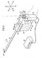
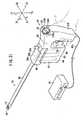
- a manipulator 10(see FIG. 1 ) according to an embodiment of the present invention comprises a medical manipulator for use in endoscopic surgical operations or the like.
- the manipulator 10includes a working unit 12 on a tip end thereof, for gripping a portion of a living tissue, a curved needle, or the like.
- the manipulator 10usually is referred to as a gripping forceps or a needle driver (needle holder).
- the manipulator 10comprises an operation command unit (operating unit) 14 on a proximal end thereof, which is held and operated by hand, a working unit 12 on a distal end thereof for working on a living tissue, and an elongate connector 16 interconnecting the working unit 12 and the operation command unit 14.
- the working unit 12 and the connector 16have small diameters and can be inserted into a body cavity 22 through a trocar 20, in the form of a hollow cylinder mounted in an abdominal region or the like of the patient.
- the working unit 12is actuated by the operation command unit 14 in order to perform various techniques to grip, remove, and/or to perform suture knot tying on an affected part of the patient's body inside of the body cavity 22.
- transverse directions of the manipulator 10are designated as X directions, vertical directions as Y directions, and longitudinal directions of the connector 16 as Z directions.
- the rightward directionis designated as an X1 direction
- the leftward directionis designated as an X2 direction
- the upward directionis designated as a Y1 direction
- the downward directionis designated as a Y2 direction
- the forward directionis designated as a Z1 direction
- the rearward directionis designated as a Z2 direction.
- these directionsrepresent directions of the manipulator 10 when it is in a neutral posture. Definitions of the above directions are given for illustrative purposes only, and the manipulator 10 can be used in any orientation, e.g., it may be used upside down.
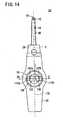
- the operation command unit 14includes a grip handle 26, which is gripped by the hand, a bridge 28 extending from an upper portion of the grip handle 26, and an actuator block 30 connected to a distal end of the bridge 28.
- the grip handle 26has a lower end connected to a lower end of the actuator block 30.
- the grip handle 26extends in the Y2 direction from the end of the bridge 28, and is of a length that is suitable for being gripped by hand.
- the grip handle 26includes a trigger lever 32 and a composite input unit 34, which serve as an input means.
- the trigger lever 32is positioned slightly beneath the bridge 28, projecting slightly in the Z1 direction.
- the trigger lever 32is disposed in a position where it can easily be pulled by the index finger of the hand while gripping the grip handle 26.
- the composite input unit 34serves as a composite input means for applying rotational commands to the working unit 12 in both rolling directions (directions about the axis) and in yawing directions (leftward and rightward directions).
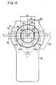
- the composite input unit 34has a circular shape when viewed in front elevation (see FIG. 15 ), and is disposed on a flat area 39 of the joint between the upper end of the grip handle 26 and the bridge 28. As can be seen from FIG. 2 , the composite input unit 34 is disposed in a position where it can easily be operated by the thumb of the hand, while gripping the grip handle 26.
- the flat area 39has a substantially annular shape, which is larger in diameter than the composite input unit 34.
- the usertypically a surgeon, places the thumb on the flat area 39, so that the user can firmly grip the grip handle 26 without touching the composite input unit 34.
- a line normal to the flat area 39 and the surface of the composite input unit 34extends along a direction that lies substantially at an intermediate position between the Z2 direction and the Y1 direction. Therefore, the user can have the finger pad T of the thumb held naturally against the flat area 39 and the surface of the composite input unit 34.
- the finger pad Trefers to the portion of the thumb, which extends from the first joint (closest to the fingertip) to the fingertip, and which lies on the same side as the palm of the hand. Details of the composite input unit 34 shall be described later.
- the actuator block 30houses therein three motors 40, 42, 44, corresponding to respective mechanisms providing three degrees of freedom, which are incorporated in the working unit 12.
- the motors 40, 42, 44are arrayed in parallel with each other in the longitudinal direction of the connector 16.
- the motors 40, 42, 44are small in size and diameter, thereby allowing the actuator block 30 to have a compact flat shape.
- the actuator block 30is disposed downwardly from the end of the operation command unit 14 in the Z1 direction.
- the motors 40, 42, 44are energized in order to rotate their drive shafts, under the control of a controller 45, based on operations of the operation command unit 14.
- the controller 45which serves to electrically control the manipulator 10, is connected by a cable 45a to a connector on the lower end of the grip handle 26.
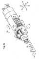
- the connector 16includes a joint 46 joined to the actuator block 30, and a hollow connector shaft 48 that extends in the Z1 direction from the joint 46.
- the joint 46houses therein drive pulleys 50a, 50b, 50c, which are connected respectively to the drive shafts of the motors 40, 42, 44.
- Wires 52, 53, 54(see FIG. 3 ) are trained respectively around the pulleys 50a, 50b, 50c, wherein the wires 52, 53, 54 extend through a space 48a in the connector shaft 48 to the working unit 12.
- the wires 52, 53, 54may be of the same type and diameter.
- the joint 46can be manually operated according to a predetermined process in order to disconnect the connector 16 from the operation command unit 14, to perform cleaning, sterilization, maintenance, etc.
- the connector 16 and the working unit 12can be replaced with other connectors and working units.
- the connector 16may be replaced by a connector having a different length and/or the working unit 12 may be replaced by a working unit incorporating different mechanisms.
- the working unit 12incorporates therein mechanisms possessing three degrees of freedom.
- These mechanismsinclude a mechanism (tilting mechanism, pivot shaft) having a first degree of freedom for angularly moving a portion of the working unit 12, which is positioned ahead of a first rotational axis Oy extending along the Y directions, in yawing directions about the first rotational axis Oy, a mechanism (rolling mechanism) having a second degree of freedom for angularly moving the portion of the working unit 12 in rolling directions about a second rotational axis Or extending along the Z directions, and a mechanism for opening and closing a gripper (opening and closing mechanism) 59 about a third rotational axis Og extending along the X directions.
- the first rotational axis Oy of the yawing mechanismhaving the first degree of freedom, extends non-parallel to an axis C of the connector 16, which extends from the proximal end to the distal end of the connector 16.
- the second rotational axis Or of the rolling mechanismhaving the second degree of freedom, extends along an axis of the working unit 12 at the tip end thereof, i.e., the gripper 59, so that the gripper 59 can roll around the second rotational axis Or.
- the working unit 12is actuated by the wires 54, 53, 52, which are trained around respective tubes 60a, 60b, 60c inside of the working unit 12.
- a gear 55, a gear 51 and a main shaft 62are rotated respectively.
- the gears 51, 55 and the main shaft 62are rotated at the same angle, the working unit 12 is rotated in the yawing direction.
- a face gearnot shown, is rotated.
- the gear 51is rotated, a face gear 57 is rotated.
- the unillustrated face gear and the face gear 57are rotated at the same angle, the working unit is rotated in the rolling direction.
- the gear 58is relatively rotated so as to open and close the gripper 59.
- the working unit 12does not incorporate a mechanism having a degree of freedom for moving the working unit 12 in pitching directions, i.e., vertical directions.
- pitching directionsi.e., vertical directions.
- the grip handle 26is oriented horizontally, so as to tilt the manipulator 10 as a whole through 90° as shown in FIG. 4 , movement of the working unit 12 in the yawing direction is converted into movement in the pitching direction. Consequently, the lack of such a pitching mechanism does not pose any practical problems.
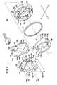
- the composite input unit 34includes a shuttle ring (first input member) 100, a substantially hollow cylindrical base body 102, a rubber pad 104, a board 106, and an O-ring 108. It is assumed that the composite input unit 34 has a central axis J, wherein the direction along the central axis J oriented toward the viewer of FIG. 5 is designated as a J1 direction, and the direction along the central axis J oriented away from the viewer of FIG. 5 is designated as a J2 direction.
- the shuttle ring 100is inserted into an inner cavity of the base body 102 along the J1 direction, and the rubber pad 104 is inserted into the inner cavity of the base body 102 along the J2 direction.
- the shuttle ring 100serves as an input means for applying a rolling command to the working unit 12. As the operating amount applied to the shuttle ring 100 increases, the rotational speed of the working unit 12 is set to become faster. Further, when the shuttle ring 100 is not operated, the working unit 12 is held at rest in the rolling directions.
- the shuttle ring 100includes a pair of knobs (finger holders) 110a, 110b disposed in diametrically symmetric positions on the side face of the shuttle ring 100 facing in the J1 direction, a pair of engaging teeth 112a, 112b disposed in upper and lower positions on the inner circumferential surface of the shuttle ring 100, a pair of protrusions 114a, 114b disposed in upper symmetric positions on the side face of the shuttle ring 100 facing in the J2 direction, and a pair of thin stoppers 116a, 116b disposed in lower symmetric positions on the side face of the shuttle ring 100 that faces in the J2 direction.
- knobsfinger holders
- the shuttle ring 100has an inside diameter D1 (distance between the knobs 110a, 110b, see FIG. 15 ) of 25 mm. Therefore, the knob 110a or 110b is spaced from the center of rotation of the shuttle ring 100 by a distance D2 (see FIG. 15 ) of 12.5 mm.
- the inside diameter D1should preferably be large enough to allow a pad 132, to be described later, to be placed in the shuttle ring 100, and should preferably be kept within a range of thumb movement so that the pad 132 can easily be operated by the thumb.
- the inside diameter D1should be within the range of from 20 mm to 40 mm (the distance D2 falls within the range of from 10 mm to 20 mm), and more preferably, should be within the range of from 25 mm to 30 mm (the distance D2 falls within the range of from 12.5 mm to 15 mm).
- the width D3should be within the range of from 5 mm to 10 mm, which is suitable for the thumb to be neatly applied to the shuttle ring 100.
- the knobs 110a, 110bhave a shape slightly protruding in the J1 direction, so that the finger pad T of the thumb can effectively be applied to the knobs 110a, 110b.
- each of the knobs 110a, 110bshould have a height within the range of from 1 mm to 5 mm, and a circumferential length D5 (see FIG. 15 ) within the range of from 3 mm to 10 mm.
- the knobs 110a, 110bare disposed in symmetrical positions, which are spaced from each other diametrically across the axis J.
- the protrusions 114a, 114bhave respective slanted surfaces 118.
- the base body 102has an inner tube 120, disposed in the inner cavity thereof, and an outer tube 126, disposed radially outwardly of the inner tube 120.
- the inner cavity of the base body 102includes two guide holes 122, two holes 123 in which the protrusions 114a, 114b are inserted, and engaging portions (not shown), wherein the engaging teeth 112a, 112b engage with the engaging portions and undergo circumferential movement therewith.
- the distance between the inner tube 120 and the outer tube 126is substantially equal to the width D3, so that the shuttle ring 100 can be angularly movable between the inner tube 120 and the outer tube 126.
- the stoppers 116a, 116bare inserted respectively into the guide holes 122.
- the shuttle ring 110is angularly movable within a range defined by the ends of the guide holes 122, which are engageable by the stoppers 116a, 116b.
- the shuttle ring 110is angularly movable within a range of ⁇ 10° about its central position.
- the angularly movable range of the shuttle ring 110should be large enough to allow the user to move the shuttle ring 110 effectively, e.g., to move the shuttle ring 110 a small interval, and the range should preferably be within a movable range of the finger pad T, so as to allow the user to move the shuttle ring 110 easily with the finger pad T.
- the angularly movable range of the shuttle ring 110should preferably be within a range of from ⁇ 5° to ⁇ 20° and, more preferably, should be within a range of from ⁇ 5° to ⁇ 10°.
- the base body 102has two springs 124a, 124b on a surface thereof facing in the J2 direction.
- the stopper 116acompresses the spring 124a, which produces a force that acts to return the shuttle ring 100 counterclockwise.
- the stopper 116bcompresses the spring 124b, which produces a force that acts to return the shuttle ring 100 clockwise.
- the base body 102has a flange 128 on an end thereof facing in the J2 direction. Axial ends of the inner and outer tubes 120, 126 are joined to the flange 128. The O-ring 108 is held against the flange 128.
- the rubber pad 104comprises a thin circular sheet 130, a pad (second input member) 132 projecting from the circular sheet 130 in the J1 direction, a pair of bearing ledges 134a, 134b disposed symmetrically on the circular sheet 130 and projecting in the J1 direction, and a clearance 136 defined in an upper portion of the circular sheet 130.
- the circular sheet 130has a plurality of screw holes 138 defined therein.
- the pad 132serves as an input means for applying a yawing command to the working unit 12. As the operating amount applied to the pad 132 increases, the speed at which the working unit 12 is tilted in a yawing direction increases. When the pad 132 is not operated, the working unit 12 is held at rest in the yawing directions.
- the pad 132is in the form of a protrusion, having upper and lower surfaces extending parallel to each other, as well as arcuate left and right sides.
- the arcuate left and right endshave a radius of curvature corresponding to the radius of curvature of inner circumferential surfaces of the inner tube 120 and the shuttle ring 100 (see FIG. 15 ).
- the pad 132has an end 133 facing in the J1 direction and having a curved surface, including a slightly dented central area and left and right slanted surfaces 133a, 133b, extending from the central area toward the left and right sides thereof.
- the end 133has a low boss 135 in the central area thereof, which allows the left and right slanted surfaces 133a, 133b to be easily recognizable by tactile sensation.
- Each of the left and right slanted surfaces 133a, 133bhas a width D4 of 5 mm, which is suitable for the thumb to be neatly applied thereto. As with the width D3, the width D4 (see FIG. 15 ) should be within a range of from 5 mm to 10 mm.
- the pad 132has a width D6 of 17 mm in a direction perpendicular to the direction in which the pad 132 is tiltable.
- the width D6is suitable for natural positioning of the thumb and corresponds to the movable range of the thumb.
- the width D6should be within a range of from 10 mm to 25 mm, for allowing the thumb to operate the pad 132 easily.
- the pad 132comprises a solid member, making up a substantially half portion of the pad 132 which extends in the J1 direction, and a protrusion 137, making up a remaining substantially half portion thereof which extends in the J2 direction.
- the pad 132further includes an outer wall, surrounding the protrusion 137 and spaced from the protrusion 137 by a gap.
- the protrusion 137has an end surface 139 facing in the J2 direction, and which is spaced slightly from the circular sheet 130 in the J1 direction.
- the end surface 139 and the board 106are spaced from each other by a gap 140.
- the gap 140(along with gaps 145, 160, 187 and 188 to be described later) is set to about 1 mm, for example.
- the pad 132 and the circular sheet 130are joined to each other by a joint, including a folded web 142.
- the pad 132can easily be tilted in a given direction depending on whether the left slanted surface 133a or the right slanted surface 133b is pressed.
- the pad 132automatically springs back to its neutral position due to the resilient force of the folded web 142.
- Each of the bearing ledges 134a, 134bhas a slanted surface 141 (see FIG. 11 ), having an upper end which is higher than the lower end thereof.
- the bearing ledges 134a, 134bare disposed slightly upwardly from the respective protrusions 114a, 114b. When the pad 132 is in a neutral position, the slanted surfaces 118 and the slanted surfaces 141 face each other.
- the circular sheet 130has shallow recesses 143a, 143b defined in a surface thereof behind the respective bearing ledges 134a, 134b, and providing gaps 145 between the bearing ledges 134a, 134b and the board 106.
- small protrusions 147are provided on the recesses 143a, 143b, the protrusions 147 being held in point contact with the board 106.
- the board 106has a hexagonal shape.
- the board 106supports, on a surface thereof facing in the J1 direction, a turn-detecting first pressure-sensitive sensor 144a, a turn-detecting second pressure-sensitive sensor 144b, a tilt-detecting first pressure-sensitive sensor 146a, and a tilt-detecting second pressure-sensitive sensor 146b.
- the sensorsare formed by fine printed patterns, which are covered with a thin resin sheet 148 such that the sensors are not directly exposed to air.
- the sensors 144a, 144b, 146a, 146bmay be of any of various types, which are capable of detecting angular displacements of the shuttle ring 100 and tilting of the pad 132.
- the sensors 144a, 144b, 146a, 146bmay comprise resistive sensors made up of conductive plastics, semiconductor sensors, optical sensors, or the like.
- the sensors 144a, 144b, 146a, 146bneed not necessarily be able to continuously detect angular displacements and tilts, but may be combined with an on-off switch that detects only a neutral position or a direction of the angular displacements and tilts.
- the turn-detecting first pressure-sensitive sensor 144a and the turn-detecting second pressure-sensitive sensor 144bare disposed in respective positions, i.e., in the recesses 143a, 143b, facing the surface of the circular sheet 130 behind the bearing ledges 134a, 134b.
- the tilt-detecting first pressure-sensitive sensor 146a and the tilt-detecting second pressure-sensitive sensor 146bare disposed in respective positions, facing respective left and right portions 139a, 139b of the end surface 139 of the pad 132.
- a plurality of electronic parts 149(see FIG. 11 ), for adjusting detected signals from the sensors 144a, 144b, 146a, 146b and supplying such adjusted signals to the controller 45, are mounted on the surface of the board 106 that faces in the J2 direction.
- the board 106comprises a connector 150 connected to the controller 45, and a plurality of screw holes 152 through which the board 106 is fastened to the grip handle 26 by screws.
- the connector 150has terminal ends slightly projecting in the J1 direction and accommodated within the clearance 136 for protecting the circular sheet 130 from damage.
- the screw holes 138 and the screw holes 152are held in registry with each other. Screws 154 are inserted into the screw holes 138 and 152 in order to firmly secure the circular sheet 130 and the board 106 to each other (see FIG. 11 ).
- the right slanted surface 133b of the pad 132When the right slanted surface 133b of the pad 132 is pushed down to tilt the pad 132 to the right, the right portion 139b of the end surface 139 presses against the tilt-detecting second pressure-sensitive sensor 146b. Tilting of the pad 132 to the right and/or the pressing force of the pad 132 can be detected as a result of signals generated by the tilt-detecting second pressure-sensitive sensor 146b.
- the tilt-detecting first pressure-sensitive sensor 146a and the tilt-detecting second pressure-sensitive sensor 146bare spaced from each other by a suitable distance R such that, when the pad 132 is in its neutral position, a gap 140 exists between the end surface 139 and the board 106.
- a pressing force that presses the left portion 133a of the pad 132is represented by - ⁇
- a pressing force that presses the right portion 133bis represented by + ⁇
- an output O1 of the tilt-detecting first pressure-sensitive sensor 146ais indicated in the plus direction of the longitudinal axis
- an output 02 of the tilt-detecting second pressure-sensitive sensor 146bis indicated in the minus direction of the longitudinal axis.
- both the outputs O1 and O2are zero in the range of ⁇ ⁇ 0 with reference to the original point as the neutral position, and thus a dead zone is obtained.
- the dead zoneserves as play in the movement of the pad 132, whereby response sensitivity of the operating unit is suitably reduced and a user can easily operate the pad 132.
- the distance Rmay be within a range of from 2 mm to 8 mm in order to provide a suitable dead zone.
- the tilt-detecting first pressure-sensitive sensor 146a and the tilt-detecting second pressure-sensitive sensor 146breliably output signals indicating the neutral position, thereby preventing the working unit 12 from being tilted in a yawing direction against the will of the user.
- the tilt-detecting first pressure-sensitive sensor 146a and the tilt-detecting second pressure-sensitive sensor 146bare suitably spaced away from each other, and the end surface 139 is gently convex downward. Owing to this structure, even if the pad 132 is pushed down without the tilting motion, no pressure is applied to the tilt-detecting first pressure-sensitive sensor 146a or the tilt-detecting second pressure-sensitive sensor 146b. Accordingly, the working unit 12 is not operated in the yawing direction unintentionally.
- the above-mentioned pushing operation of the pad 132may be regarded as a preparing operation. Further, the user may recognize that the working unit 12 is operated in the yawing direction by tilting the pad 132 after the preparing operation. In this case, since the preparing operation, i.e., the pushing operation of the pad 132 is added before the tilting operation of the pad 132, the operation for moving the working unit 12 in the yawing direction is regarded as a two-stage operation. Such a two-stage operation is effective in operating the working unit 12 slowly and reliably.
- the distance Rshould be within a range of from 2 mm to 8 mm in order to provide a moderate dead zone.
- the shuttle ring 100when the thumb is spaced from the shuttle ring 100, the shuttle ring 100 is held in a neutral position under the resiliency of the springs 124a and 124b.
- the protrusions 114a, 114bengage with the bearing ledges 134a, 134b, due to resiliency of the rubber pad 104, the protrusions 114a, 114b are subjected to forces tending to return the protrusions 114a, 114b. Therefore, the shuttle ring 100 also is held in a neutral position by the bearing ledges 134a, 134b.
- the shuttle ring 100When the thumb is applied to the knob 110b and pulls the knob 110b so as to turn the shuttle ring 100 clockwise, the shuttle ring 100 also is moved angularly clockwise. Therefore, the angular displacement of the shuttle ring 100 in the clockwise direction can be detected as a result of the signal produced by the turn-detecting first pressure-sensitive sensor 144a.
- the turn-detecting first pressure-sensitive sensor 144a and the turn-detecting second pressure-sensitive sensor 144breliably output signals indicative of the neutral position. Accordingly, the working unit 12 is prevented from being turned in a rolling direction against the will of the user. Due to the angular movement dead zone, when the user takes his thumb out of contact with the shuttle ring 100, even if the shuttle ring 100 is slightly displaced from a neutral state (ex. two springs 124a and 124b do not balance with each other), the turn-detecting first pressure-sensitive sensor 144a and the turn-detecting second pressure-sensitive sensor 144b reliably output signals indicative of the neutral position. Accordingly, the working unit 12 is prevented from being turned in a rolling direction uselessly.
- Such a dead zonepreferably should be within a range of from ⁇ 1° to ⁇ 8° in terms of angular displacements of the shuttle ring 100.
- Such a dead zone as indicated by ⁇ ⁇ 0 in FIG. 10can be obtained by a software process in the controller 45. Further, a more reliable dead zone can be obtained by a mechanical structure based on the presence of gaps 145, 160 and the distance R. For example, if there is no gap between the tilt-detecting first pressure-sensitive sensor 146a and the tilt-detecting second pressure-sensitive sensor 146b, and the pad 132 is pushed down, both the tilt-detecting first pressure-sensitive sensor 146a and the tilt-detecting second pressure-sensitive sensor 146b output signals that are based on the pressing force. In this case, it is difficult to form an appropriate dead zone by a software process. Such a difficulty causes complicated procedures, an increased program size and a longer debugging time.
- the angle ⁇ 1 formed between the axis C of the connector shaft 48 and the plane in which the shuttle ring 100 rotatesi.e., the angle formed between surfaces of the composite input unit 34 and the flat area 39, is set to 45°.
- the angle ⁇ 1preferably should be within a range of from 35° to 55°, so that the shuttle ring 100 matches the natural positioning of the thumb as well as the movable range of the thumb.
- the shuttle ring 100has a vertical central line 170, which is aligned with the longitudinal axis C of the connector shaft 48 when viewed along the rotational axis J of the shuttle ring 100. Consequently, the user feels as though the rolling mechanism of the working unit 12 operates concentrically with the shuttle ring 100, and in direct relationship thereto. Therefore, the user can easily operate the manipulator 10.
- the manipulator 10can be used by either the right hand or the left hand.
- the manipulator 10is illustrated in perspective, for enabling understanding of the way in which the manipulator 10 is seen from the viewpoint of the user.
- the pad 132which is centered about the J axis, and the shuttle ring 100 are disposed coaxially in a concentrated and compact configuration.
- the working unit 12When the user applies the thumb to either one of the knobs 110a, 110b and pushes the knobs upwardly so as to turn the shuttle ring 100 in one direction, the working unit 12 is turned (i.e., rolls) in the same direction. Therefore, the rolling mechanism of the working unit 12 and the shuttle ring 100 both turn in the same direction, so that the user is able to operate the working unit 12 easily and intuitively. Furthermore, the single shuttle ring 100 allows the rolling mechanism to turn in opposite directions. Therefore, the shuttle ring 100 does not require an increased number of input members, but is simple in structure and easy to operate.
- the shuttle ring 100Since the shuttle ring 100 has an annular shape, the shuttle ring 100 is easily visually recognized as the input means for entering rolling commands. Further, the user can easily learn and will not quickly forget how to use the shuttle ring 100.
- the operation command unit 14may also be designed to incorporate another input means for entering rolling commands.
- the operation command unit 14may comprise an input means which turns in an arc and can be moved angularly around the axis J, wherein only the knobs 110a, 110b are exposed on the surface, or a C-shaped ring that is partially open.
- the shuttle ring 100 and the pad 132are disposed in a concentrated fashion, since they are mechanically separate from each other, the user can easily operate the shuttle ring 100 and the pad 132 separately from each other, and the user does not become confused when using them.
- the pad 132is located inside of the shuttle ring 100, and hence the pad 132 is compact and can be operated by moving the thumb within a small range.
- the single pad 132allows the yawing mechanism to turn in opposite yawing directions. Therefore, the pad 132 does not require an increased number of input members, but is simple in structure and easy to operate.
- the knobs 110a, 110b and the pad 132are thus positioned inside of the movable range of the finger pad T of the thumb, and thus can be operated highly effectively.
- the finger pad T of the thumbis naturally placed near to the central boss 135 of the pad 132. If the thumb is movable within a general range defined by an angle ⁇ 2, which is achieved when the second joint (central joint) of the thumb and the third joint (proximal joint) of the thumb are moved, then the knobs 110a, 110b and the pad 132 are positioned inside of an arcuate range 162, in which the finger pad T moves. Accordingly, the knobs 110a, 110b and the pad 132 can be operated in a concentrated fashion by the thumb, without causing any undue motion of the thumb.
- the angular movable range of the shuttle ring 100has an appropriately wide range of ⁇ 10° regulated by the stoppers 116a, 116b. Therefore, the user can move the shuttle ring 110 by a small interval, and can move the shuttle ring 110 easily with the finger pad T.
- the surface of the composite input unit 34lies substantially flush with the flat area 39, except that the knobs 110a, 110b and the boss 135 project slightly from the surface of the composite input unit 34. Therefore, when the user moves the finger pad T in X directions, the finger pad T is simply moved along the substantially flat surface of the composite input unit 34, whereby the user can operate the composite input unit 34 easily.
- the useroperates the composite input unit 34 as follows:
- the usermoves the finger pad T from the boss 135 onto the left slanted surface 133a and depresses the left slanted surface 133a. Since the left slanted surface 133a is free of the boss 135, and also is positioned to the right of the knob 110a, the user can easily confirm the position of the left slanted surface 133a through tactile sensation, without requiring the user to look at the hand.
- the usercan depress the right slanted surface 133b, and also can easily confirm the position of the right slanted surface 133b, in the same manner as the position of the left slanted surface 133a.
- the usermoves the finger pad T further to the left until the finger pad T hits against the knob 110a, and then pushes the knob 110a upwardly or pulls the knob 110a downwardly.
- the finger pad Tnaturally touches the knob 110a. Therefore, the user can easily confirm the position of the knob 110a.
- the usercan operate the knob 110b to roll the working unit 12, wherein the user can easily confirm the position of the knob 110b, similar to the position of the knob 110a. Since the knobs 110a, 110b protrude appropriately from the surface of the composite input unit 34, the knobs 110a, 110b can easily be pushed upwardly or pulled downwardly with a light force.
- the userplaces the thumb on the flat area 39. If the user wants to move the working unit 12 in a rolling or yawing direction with the thumb, after the thumb has been placed on the left end of the flat area 39, then the user moves the finger pad T to the right along the flat area 39 and the composite input unit 34. Since the finger pad T naturally touches the knob 110a, the left slanted surface 133a, the right slanted surface 133b, and the knob 110b in succession, the user can confirm such positions through tactile sensation, without requiring the user to look at the hand.
- the working unit 12can be both rolled and yawed in a composite motion using a single thumb. For example, if the working unit 12 is to be yawed to the left and rolled clockwise, the user places the thumb on both the left slanted surface 133a and the knob 110a, while depressing the left slanted surface 133a and pushing the knob 110a upwardly. If the working unit 12 is to be yawed to the right and rolled clockwise, the user places the thumb on both the right slanted surface 133b and the knob 110b, while depressing the right slanted surface 133b and pulling the knob 110b downwardly.
- the manipulatoris easy to operate, owing to the presence of a dead zone in each motion.
- the manipulator 10can be positioned easily and fixed with respect to an affected area of the patient. Further, for many types of surgical cases, the manipulator 10 can be prepared in a short period of time before each surgical operation, can be positioned flexibly for each surgical case, and does not pose a burden when drawing up operation protocols. Even if an unexpected trouble happens during a surgical operation when using the manipulator 10, for example, if the operation needs to be changed to a thoracotomy or a laparotomy, removal of the manipulator does not consume essential time so that the period of the operation is not unduly increased, resulting in a procedure which is highly non-invasive to the patient. Moreover, the manipulator 10 is simpler in structure and less expensive to manufacture than a remote control system.
- the turn-detecting first pressure-sensitive sensor 144a and the turn-detecting second pressure-sensitive sensor 144bare arranged such that the dead zone for operation of the shuttle ring 100 is obtained with reference to the neutral position. Also, the tilt-detecting first pressure-sensitive sensor 146a and the tilt-detecting second pressure-sensitive sensor 146b are arranged such that the dead zone for operation of the pad 132 is obtained with reference to the neutral position. With the above arrangement, there is play in each motion, and such play prevents a useless motion of the working unit 12 and an excessive reaction of the working unit 12 by slightly touching the input unit, thereby obtaining a high operability.
- the working unit 12is moved to the right and left in a yawing direction and is turned clockwise and counterclockwise in response to the right and left operations and the clockwise and counterclockwise operations of the input unit with reference to the neutral position, respectively, thereby enabling a user to operate the manipulator intuitively.
- the shuttle ring 100 and the pad 132are arranged concentratedly on the composite input unit 34, the shuttle ring 100 and the pad 132 can be operated by moving the thumb within a small range. Further, the complex motion of the shuttle ring 100 and the pad 132 can be easily performed by one finger.
- the rolling motion of the shuttle ring 100corresponds to the rolling motion of the working unit 12
- the tilting motion of the pad 132corresponds to the tilting motion of the working unit 12 in the yaw axis.
- the shuttle ring 100surrounds the pad 132 entirely, and the shuttle ring 100 is disposed in a well-balanced fashion, in coaxial relation to the center of the pad 132 (the axis J).
- the shuttle ring 100 and the pad 132thus can be operated highly effectively and smoothly, allowing the user easily to learn how to use them.
- the effect of the well-balanced fashionis due to the surrounding of the pad 132 by the shuttle ring 100 at least with respect to the tilting directions of the pad 132.
- the usercan easily confirm the position of the shuttle ring 100 and the pad 132 through tactile sensation, without requiring the user to look at the hand and can operate them highly effectively and smoothly.
- the above composite input unitmay appropriately be applied to perform fine techniques for a long time.
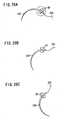
- FIGS. 16A through 17shows shuttle rings 100a, 100b, 100c, which make up input means according to respective modifications of the shuttle ring 100. Operation of the shuttle rings 100a, 100b, 100c is equally favorable to that of the shuttle ring 100. Also, in the shuttle rings 100a through 100c, a dead zone with reference to a neutral position is provided, as with the shuttle ring 100.
- the shuttle ring 100a shown in FIG. 16Aincludes a pair of recesses (finger holders) 190a, 190b instead of the knobs 110a, 110b.
- the recesses 190a, 190bare slightly dented in the J2 direction for receiving and being pressed by the finger pad T of the thumb.
- each of the recesses 190a, 190bmay have a depth within a range of from 1 mm to 5 mm, and a circumferential length within a range of from 3 mm to 10 mm.
- the recesses 190a, 190bare disposed in symmetrical positions, which are spaced from each other diametrically across the axis J.
- the shuttle ring 100b shown in FIG. 16Bincludes a pair of upper and lower small knobs 192a, 193a instead of the knob 110a, and a pair of upper and lower small knobs 192b, 193b instead of the knob 110b.
- the upper and lower small knobs 192a, 193aare disposed in vertically symmetrical positions, with a recess (finger presser) 194a defined therebetween.
- the upper and lower small knobs 192b, 193bare disposed in vertically symmetrical positions, with a recess (finger presser) 194b defined therebetween.
- the recesses 194a, 194bare slightly dented in the J2 direction for receiving and being pressed by the finger pad T of the thumb.
- the recesses 194a, 194bmay be positioned and shaped similarly to the recesses 190a, 190b.
- the shuttle ring 100c shown in FIG. 17includes a single slender protrusion 180 instead of the protrusions 114a, 114b.
- the protrusion 180is positioned between left and right rubber members 182a, 182b, which are joined by a folded web 184 to a base 186 of the grip handle 26.
- the rubber members 182a, 182bare elastically deformable circumferentially upon flexure of the folded web 184.
- the turn-detecting first pressure-sensitive sensor 144a and the turn-detecting second pressure-sensitive sensor 144bare disposed across the rubber members 182a, 182b from the protrusion 180. In the neutral position, narrow gaps 187 are provided between the protrusion 180 and the rubber members 182a, 182b, and further, narrow gaps 188 are provided between the rubber members 182a, 182b and the turn-detecting first and second pressure-sensitive sensors 144a, 144b.
- the protrusion 180When the shuttle ring 100c is turned clockwise, the protrusion 180 is displaced to the left, as shown in FIG. 17 , causing the rubber member 182a to press the turn-detecting first pressure-sensitive sensor 144a, which detects a clockwise angular displacement of the shuttle ring 100c.
- the protrusion 180When the shuttle ring 100c is turned counterclockwise, the protrusion 180 is displaced to the right, as shown in FIG. 17 , causing the rubber member 182b to press the turn-detecting second pressure-sensitive sensor 144b, which detects a counterclockwise angular displacement of the shuttle ring 100c.
- the gaps 187, 188provide a dead zone during movement of the shuttle ring 100c, for thereby preventing the working unit 12 from being operated against the will of the user.
- the dead zoneprovides a certain amount of play, which allows the user to operate the shuttle ring 100c easily.
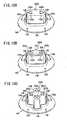
- FIGS. 18A through 18Cshow pads 200a, 200b, 200c, forming input means according to respective modifications of the pad 132. Operability of the pads 200a, 200b, 200c is equally favorable to that of the pad 132.
- the pad 200adoes not contain the boss 135, but includes outwardly-pointed triangular lands 202a, 202b, disposed respectively on left and right slanted surfaces 133a, 133b. Even in the absence of the boss 135, the triangular lands 202a, 202b allow the user to recognize the positions of the left and right slanted surfaces 133a, 133b through tactile sensation. The user can also recognize the orientations indicated by the triangular lands 202a, 202b, through visual or tactile sensation, so as to recognize the yawing direction in which the working unit 12 is tilted.
- the pad 200bincludes a roof-shaped boss 135, which is smoothly joined to a left semicircular plate 204a placed on the left slanted surface 133a, and to a right semicircular plate 204b placed on the right slanted surface 133b.
- the semicircular plates 204a, 204bhave respective shallow gradual recesses 206 defined therein.
- the roof-shaped boss 135 of the pad 200ballows the user to distinguish between the left and right slanted surfaces 133a and 133b.
- the semicircular plates 204a, 204balso allow the user to recognize the positions of the left and right slanted surfaces 133a and 133b. Because of the recesses 206, the user can easily apply the thumb to the semicircular plates 204a, 204b, thereby improving operability of the pad 200b.
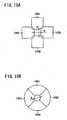
- the pad 200ccomprises a combination made up of the pad 200a shown in FIG. 17A , which acts as a horizontal switch 209, together with a vertical switch 208 added thereto.
- the vertical switch 208 and the horizontal switch 209are jointly provided in a crisscross shape.
- the switch 208includes outwardly-pointed triangular lands 202c, 202d disposed on upper and lower portions thereof, respectively.
- the pad 200cpermits entry of commands through the composite input unit 34 in a concentrated manner, wherein such commands are supplied to a mechanism for operating the working unit 12 in directions other than yawing directions, e.g., for opening and closing the gripper 59, or for moving the working unit 12 in pitching directions.
- a working unit 220see FIG. 23
- the horizontal switch 209is assigned to yaw axis movements and the vertical switch 208 is assigned to pitch axis movements thereof
- the directions in which the switches extend and the directions in which the switches are pushedcorrespond to the directions in which the yaw and pitch axis movements are made. Therefore, the pad 200c allows a user to operate the working unit 12 intuitively.
- the tilt-detecting first pressure-sensitive sensor 146a and the tilt-detecting second pressure-sensitive sensor 146bare positioned beneath the horizontal switch 209, while a tilt-detecting third pressure-sensitive sensor 146c and a tilt-detecting fourth pressure-sensitive sensor 146d are positioned beneath the vertical switch 208.
- the pad 200chas an end surface 139 in the J2 direction, which has a crisscross shape. When the pad 200c is tilted in vertical (opposite) directions, the tilting and/or pressing forces applied thereto are detected by the tilt-detecting third pressure-sensitive sensor 146c and the tilt-detecting fourth pressure-sensitive sensor 146d.
- the tilt-detecting first pressure-sensitive sensor 146a and the tilt-detecting second pressure-sensitive sensor 146bare horizontally spaced from each other by the distance R. Further, the tilt-detecting third pressure-sensitive sensor 146c and the tilt-detecting fourth pressure-sensitive sensor 146d are vertically spaced from each other by the distance R. Therefore, an appropriate dead zone is provided within the vertical tilting movements of the pad 200c.
- the tilt-detecting first pressure-sensitive sensor 146a, the tilt-detecting second pressure-sensitive sensor 146b, the tilt-detecting third pressure-sensitive sensor 146c, and the tilt-detecting fourth pressure-sensitive sensor 146dmay each have an arcuate shape of about 90°, wherein the sensors are disposed in left, right, upper, and lower positions, respectively, so as to jointly form an annular shape.
- the end surface 139 of the pad in the J2 directionhas a circular shape.
- the annular shapewhich is provided jointly by the tilt-detecting first pressure-sensitive sensor 146a, the tilt-detecting second pressure-sensitive sensor 146b, the tilt-detecting third pressure-sensitive sensor 146c and the tilt-detecting fourth pressure-sensitive sensor 146d, preferably has a diameter that is equal to the distance R. Therefore, an appropriate dead zone is established during each of horizontal and vertical tilting movements of the pad.
- the pad 200cis tilted in horizontally pushed directions in order to supply operation commands to a first rotational axis, e.g., a pivot axis. Further, the pad 200c is tilted in vertically pushed directions in order to supply operation commands to a second rotational axis, e.g., the gripper 59.
- the tilt-detecting first pressure-sensitive sensor 146a and the tilt-detecting second pressure-sensitive sensor 146bare a set of sensors for detecting right and left tilts, and are defined as a first set of sensors. These sensors face right and left portions of the end surface 139 respectively and are arranged with gaps therebetween.
- the tilt-detecting third pressure-sensitive sensor 146c and the tilt-detecting fourth pressure-sensitive sensor 146dare a set of sensors for detecting a vertical tilt, and are defined as a second set of sensors. These sensors face upper and lower portions of the end surface 139 respectively and are arranged with gaps therebetween.
- the vertical switch 208 of the pad 200cis referred to as the third input member of the composite input unit 34.
- the vertical switch 208is integrally combined with the horizontal switch 209 (referred to as the second input member) of the pad 200c. Therefore, the vertical switch 208 and the horizontal switch 209 can be operated effectively and smoothly.
- FIG. 20shows the composite input unit 34 incorporating the pad 200c.
- the shuttle ring 100 forming the first input membersurrounds the vertical switch 208 and the horizontal switch 209.
- the shuttle ring 100, the vertical switch 208, and the horizontal switch 209are disposed in a well-balanced fashion, in coaxial relation to the axis J.
- the shuttle ring 100, the vertical switch 208, and the horizontal switch 209thus can be operated highly effectively and smoothly, allowing the user easily to learn how to use them.
- the vertical switch 208is assigned to open and close the gripper 59, then since the gripper 59 is made up of a mechanism that can be opened and closed vertically while in a neutral position, the gripper 59 matches well with the vertical tilting movements of the vertical switch 208. Therefore, the pad 200c allows the user to operate the gripper 59 intuitively.
- the layouts of the tilt-detecting first pressure-sensitive sensor 146a, the tilt-detecting second pressure-sensitive sensor 146b, the tilt-detecting third pressure-sensitive sensor 146c, and the tilt-detecting fourth pressure-sensitive sensor 146dwhich are shown in FIGS. 19A and 19B , are effective to detect not only horizontal and vertical tilting movements of the pad 200c, but also tilting movements of the pad 200c in oblique directions. For example, if the pad 200c is tilted obliquely upwardly toward the left in FIGS.
- a tilting and/or pressing forcecan be detected based on a vectorial sum of two signals output from the tilt-detecting first pressure-sensitive sensor 146a and the tilt-detecting third pressure-sensitive sensor 146c, and hence, the direction in which the pad 200c is tilted can be detected based on the direction of such a vectorial sum.
- FIGS. 21 and 22show a manipulator 10, including a grip handle 210 as a grip means, corresponding to the grip handle 26 referred to above.
- the grip handle 210is disposed at a position that is shifted in the J1 direction from the grip handle 26. Stated otherwise, the center of rotation O of the knobs 110a, 110b is shifted upwardly from the longitudinal axis C of the connector shaft 48 in the Y1 direction, opposite to the Y2 direction in which the grip handle 26 extends.
- the center of rotation Ois spaced from the axis C by a distance D7 of 30 mm.
- the composite input unit 34Since the center of rotation O is shifted from the axis C, the composite input unit 34 also is disposed in a shifted position.
- the position at which the hand grips the grip handle 210is also shifted in the Y1 direction, with the wrist being closer to the axis C. Therefore, when the manipulator 10 is turned about the trocar 20, the wrist is rotated about its own axis, rather than revolving around the axis C. Therefore, the manipulator 10 can easily be operated simply by twisting the wrist, and not by turning the wrist through a large arcuate path around the axis C.
- the distance D7may be set to a value within a range of from 20 mm to 50 mm, for improving operability of the manipulator 10.
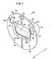
- FIG. 23shows a modified working unit 220, serving as a working means corresponding to the working unit 12 described above.
- the working unit 220comprises an electrosurgical knife for passing an electric current through a living tissue at a high frequency, in order to coagulate, cut or treat a desired area of living tissue.
- the working unit 220includes an electrode 222, which is positioned in place of the gripper 59 referred to above.
- the electrode 222projects in the Z1 direction and has a tip end bent in the Y1 direction.
- the working unit 220also includes a pitching mechanism, for turning the electrode 222 in pitching directions about an axis Op.
- the working unit 220is capable of moving the electrode 222 in yawing, pitching, and rolling directions.
- the manipulator 10incorporates the working unit 220, the manipulator further employs a power supply 224 (see FIG. 1 ) for applying a voltage between the living tissue and the manipulator 10.
- the composite input unit 34may be applied and used together with the working unit 220. Specifically, the shuttle ring 100 is turned so as to turn the electrode 222 in rolling directions, and the vertical switch 208 of the pad 200c, shown in FIG. 20 , is tilted so as to turn the electrode 222 in both yawing and pitching directions.
- the composite input unit 34may also be used with a working unit including a rolling mechanism.
- the composite input unit 34may be used with a working unit having a yaw axis, a roll axis and a gripper axis, a working unit having a yaw axis, a pitch axis, a roll axis and an electrosurgical knife electrode, or a working unit having a yaw axis, a pitch axis, a roll axis and a gripper axis.
- the gripper axis or the electrosurgical knife electrodeshould be positioned at the distal end, with the other axes thereof being arranged in any desired sequence.
- the manipulatoris used in a surgical operation for removal of the prostate gland, then the gripper axis should be positioned at the distal end, whereas the roll axis should be positioned as the second axis from the distal end.
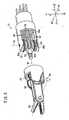
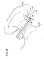
- FIG. 24shows the manner in which the working unit 12 and the gripper 59 on the distal end of the connector shaft 48 are inserted to a position near a region to be treated in a body cavity 22, and thereafter the region is sutured and a suture knot is tied, in a process of peeling off and cutting the urethra during an operation to remove the prostate gland.
- the body cavity 22 into which the manipulator 10 is insertedaccommodates therein a body cavity wall 234, a prostate gland 236, and a dorsal vein complex (DVC) 238, wherein the urethra is disposed in a rear part thereof.
- DVCdorsal vein complex
- the working unit 12is first inserted into the body cavity 22 through the trocar 20, and the working unit 12 and the gripper 59 are oriented upwardly. Specifically, as shown in FIG. 4 , the pad 132 is operated so as to orient the gripper 59 to the right, and the grip handle 26 is held substantially horizontally so that the gripper 59 is directed substantially upwardly. Then, the curved needle 230 is gripped by the gripper 59, substantially perpendicularly to the gripper 59. After the working unit 12 has been inserted into the body cavity 22, the working unit 12 is positioned slightly rightward of the DVC 238, while the gripper 59 is held substantially parallel to the DVC 238.
- the shuttle ring 100is operated in order to turn the gripper 59 in a rolling direction, to thereby introduce the gripped curved needle 230 into the DVC 238.
- the gripper 59is sufficiently turned until the tip end 230a of the curved needle 230 emerges from a face part of the DVC 238. Rolling movement of the gripper 59 is easily accomplished by pushing or pulling the knob 110a or 110b of the shuttle ring 100.
- the above movement of the gripper 59can primarily be accomplished simply by operating the shuttle ring 100. However, depending on the surgical case or situation, the gripper 59 may simultaneously be moved in yawing directions, and/or the connector shaft 48 may simultaneously be pushed or pulled, or moved vertically, in combination with the rolling movement of the gripper 59.
- the gripper 59is opened in order to release the curved needle 230, and then, the projecting tip end 230a of the curved needle 230 is gripped by the gripper 59 and pulled so as to remove the curved needle 230 through the DVC 238.
- a first piercing cycleis finished.
- successive piercing cyclesare performed and the suture 232 is tied longitudinally along the DVC 238, in a plurality of cycles following the respective piercing cycles, thereby arresting hemorrhage in the blood vessel in the DVC 238.
- the manipulator 10includes a mechanism for turning the gripper 59 on the tip end of the working unit 12, about an axis along which the gripper 59 extends, wherein the mechanism is rolled by the shuttle ring 100.
- the gripper 59is turned about its own axis as viewed from the tip end thereof, to thereby turn the curved needle 230 with ease. Since the curved needle 230 is turned based on operation of the shuttle ring 100, the curved needle 230 can easily be passed through the rear part of the DVC 238 and easily removed from the face part of the DVC 238.
- the manipulator 10 and the working units 12, 220have been illustrated as being used in medical applications. However, the manipulator 10 and the working units 12, 220 can also be used in other applications, for example, in order to repair narrow regions of energy-related devices and apparatuses.
- a manipulator (10)includes an operation command unit (14) to be gripped by a hand, a composite input unit (34) operable by a finger, a connector shaft (48) extending from the operation command unit, and a working unit (12) disposed on a distal end of the connector shaft.
- the working unit (12)includes a yawing mechanism, a rolling mechanism, and an opening and closing mechanism.
- the composite input unit (34)has a shuttle ring (100) for actuating the rolling mechanism, and a pad (132) for actuating the yawing mechanism.
- the shuttle ring (100)is an angularly movable member having two knobs (110a, 110b) disposed in respective left and right positions.
- the pad (132)is disposed inside of the shuttle ring (100).
Landscapes
- Health & Medical Sciences (AREA)
- Life Sciences & Earth Sciences (AREA)
- Surgery (AREA)
- Engineering & Computer Science (AREA)
- Medical Informatics (AREA)
- Veterinary Medicine (AREA)
- Biomedical Technology (AREA)
- Heart & Thoracic Surgery (AREA)
- Nuclear Medicine, Radiotherapy & Molecular Imaging (AREA)
- Molecular Biology (AREA)
- Animal Behavior & Ethology (AREA)
- General Health & Medical Sciences (AREA)
- Public Health (AREA)
- Robotics (AREA)
- Ophthalmology & Optometry (AREA)
- Manipulator (AREA)
- Surgical Instruments (AREA)
- Input From Keyboards Or The Like (AREA)
Abstract
Description
- The present invention relates to a manipulator having a hand-gripped operating unit, a connector extending from the operating unit, and a working unit angularly movable when the operating unit is operated.
- In endoscopic surgery (also called laparoscopic surgery), it is customary to form a plurality of incisions in the body surface of the patient, insert trocars (tubular instruments) into the respective incisions as forceps instrument passage ports, and to introduce the tip ends of forceps instruments having shafts through the respective trocars into a body cavity, to perform a surgical operation on an affected part of the body. Working units such as a gripper for gripping living tissue, scissors, an electrosurgical knife blade, etc., are mounted on the tip ends of the forceps instruments.
- An endoscopic surgical operation performed with forceps instruments requires the surgeon to be trained in advance, because the working space in the body cavity is small and the forceps instruments need to be operated using the trocars as fulcrums. Since the forceps instruments that have been used heretofore have no joints in the working unit at the tip end thereof, the forceps instruments have a small degree of freedom, and the working unit can be operated only on an extension of the shaft. Therefore, cases that can be handled under usual endoscopic surgery training practices are limited to a certain range, and surgeons need to be highly trained and quite skilled in order to be able to perform endoscopic surgery in various other cases outside of the limited range.
- Attempts have heretofore been made to improve conventional forceps instruments, in order to develop a forceps instrument having a plurality of joints in the working unit thereof (see, for example,
Japanese Laid-Open Patent Publication No. 2002-102248 - Another developed endoscopic surgical system is based on robotic technology, which is introduced into a working unit having a plurality of joints. Specifically, the endoscopic surgical system incorporates a master-slave remote control system, developed in the field of industrial robots. The surgeon is seated at a working station, i.e., a master console, spaced from a surgical bed on which the patient lies, wherein the surgeon moves an operating handle in order to perform operations while watching a display monitor. The surgical bed is equipped with a robotic arm, i.e., a slave manipulator, on which a forceps instrument is mounted. The forceps instrument includes a shaft inserted through a trocar into the body cavity of the patient. When the surgeon moves the operating handle, motion is converted into electric signals, which are supplied to a computer in order to move the working unit on the distal end of the forceps instrument, which reaches the affected part of the patient.
- Since the working unit on the tip end of the forceps instrument has a plurality of joints, the working unit can move with a high degree of freedom, reflecting wrist motions of the surgeon. Because of the robotic arm, the tip end of the forceps instrument can be positioned within the body cavity by the operating handle. Therefore, limitations imposed by using a trocar acting as a fulcrum are eliminated.
- However, it has been pointed out that surgical operations performed with a master-slave robot suffer from the following problems: 1. Since the slave manipulator constructed as a robotic arm needs to be positioned and fixed in advance, it takes time to prepare for surgery. 2. Since it is also necessary to position the robotic arm in advance for each surgical case, it is burdensome to draw up operation protocols, and such procedures are not applicable to certain surgical cases. 3. If unexpected trouble happens during the surgical operation, and the operation needs to be changed to a thoracotomy or a laparotomy, then since it is time-consuming to remove the robotic arm, the duration of the operation increases, resulting in a highly invasive situation for the patient. 4. The overall endoscopic surgical system is complex in structure, large in scale, and highly expensive to manufacture.
- Efforts have been made to dispense with such a master-slave system, and improve the forceps instrument so as to act as a manipulator having a compact working unit on its tip end and a higher degree of freedom, whereby the forceps instrument itself is applicable to a variety of surgical cases and is easily operable.
- For developing such a manipulator, it is important to develop not only a working unit on the tip end of the manipulator, but also to provide an operating means for use in combination therewith. This is because the increased degree of freedom of the working unit results in an increased number of input members, which makes the working unit complex to operate, for example. Further, it is time-consuming for the surgeon to confirm operation of the working unit in yawing and rolling directions, and also in positive and negative directions, so that the manipulator cannot be operated using easy techniques.
- In particular, there have been demands for a manipulator, which is capable of rolling the working unit easily, as well as an operating means for such a manipulator, for use in endoscopic surgical operations in which suture knot tying is an indispensable task.
- In particular, endoscopic surgery often requires fine manipulations in long hours. Accordingly, there have been demands for a manipulator which can be operated easily and intuitively even during a complex joint motion of a working unit of the manipulator.
- When the operating unit needs to be halted without operation, a user releases the hand from the input unit to maintain the input unit at a neutral position. However, if the input unit is slightly displaced from the neutral position, the operating unit undesiredly continues to move in one of opposite directions at a low speed. Also, even if the input unit is maintained at the neutral position, when an unintentional slight touch on the input unit results in moving the operating unit, a user cannot operate it easily. Stated otherwise, when response sensitivity of the manipulator is too high, the manipulator is not easy for the user to operate.
- Document
DE 41 36 861 A1 discloses a surgical instrument according to the preamble of claim 1 comprising two switches, a wobble switch and a swing switch. The wobble switch serves to position a moveable part via an electric drive, and the swing switch serves to tilt or rotate the moveable part. Further, the swing switch is arranged below the wobble switch, wherein both switches can be operated by the thumb. - It is one of the objects of the present invention to provide a manipulator, which is capable of rolling a working unit with ease, while allowing a user to learn how to operate the manipulator within a short period of time during a training process.
- It is one of the objects of the present invention is to provide a manipulator, which is capable of tying a suture knot in a living tissue inside a deep and narrow area within a body cavity.
- It is one of the objects of the present invention is to provide a manipulator in which a user can control easily and intuitively a complex motion of a working unit.
- It is the main object of the present invention is to provide a manipulator which can be operated intuitively and which has a high operability.
- The above object is solved by a manipulator stated in claim 1. Further developpments are stated in the further claims.
- The manipulator according to claim 1 of the present invention comprises an operating unit including a grip handle to be gripped by a hand, a first input unit mounted on the operating unit and operable by the thumb while gripping the grip handle, a connector extending from the operating unit, and a working unit disposed on a distal end of the connector and including a rotating mechanism angularly movable about an axis along which a distal end of the working unit extends, based on operation of the first input unit, wherein the first input unit comprises a rotary ring member including at least two finger holders disposed at left and right positions, respectively, on each side of a central line of the rotary ring member as viewed in front elevation.
- The first input unit as viewed in front elevation is defined as the first input unit viewed along an axis of rotation of the first input unit. The left and right positions are defined as positions recognized when the grip handle is oriented downwardly.
- When the user applies a thumb, for example, to either one of the finger holders and pushes the finger holder upwardly, the first input unit is turned, so as to turn the rotating mechanism about an axis in the same direction as the first input unit. Since the rotating mechanism and the first input unit operate substantially in the same manner, the user can operate the working unit easily and intuitively. Furthermore, the first input unit allows the rotating mechanism to turn in opposite directions. Therefore, the first input unit does not require an increased number of input members, and hence the operating unit is simple in structure and easy to operate. The two finger holders allow the user to confirm the position of the first input unit through tactile sensation, without the need to observe the hand, and also allow the user to operate the first input unit under a light force without slippage.
- The operating unit may include a second input unit disposed within an angularly movable range of the two finger holders and operable by the finger, so as to be tilted in horizontally pushed directions. Also, the working unit may include a pivot axis about which the working unit is angularly movable and which is non-parallel to an axis that extends from a proximal end of the connector to the distal end thereof, based on operation of the second input unit.
- The first input unit may have an annular shape when viewed in front elevation, wherein the operating unit may include a second input unit, disposed within the first input unit and operable by the finger so as to be tilted in vertically pushed directions. Also, the working unit may include a pivot axis about which the working unit is angularly movable and which is non-parallel to an axis that extends from a proximal end of the connector to the distal end thereof, based on operation of the second input unit.
- Because the first input unit and the second input unit are independent of each other, the user finds it easy to turn the rotating mechanism and the pivot axis separately from each other, and the user does not become confused when operating the first input unit and the second input unit. The second input unit is disposed inside of a range in which the two finger holders are angularly movable. Therefore, the operating unit consists of a compact input means, which allows the finger to move over a short distance, while also allowing the first and second input units to be operated with a single finger. The second input unit allows the pivot axis to turn in opposite directions. Therefore, the second input unit does not require an increased number of input members, but rather, is simple in structure and easy to operate.
- The first input unit may be angularly movable within a range of from ± 5° to ± 20°. The first input unit may have a center of rotation spaced from each of the finger holders by a distance within a range of from 10 mm to 25 mm. An angle formed between an axis along which the connector extends and a rotational plane of the first input unit may be within a range of from 35° to 55°. With these numerical settings, the first input unit is suitable for naturally positioning the thumb, and corresponds to the movable range of the thumb, thereby allowing the thumb to operate the first input unit easily.
- The first input unit, when viewed in front elevation, may have a vertical central line aligned with an axis along which the connector extends. With this arrangement, the user is able to feel as though the first input unit and the rotating mechanism operate concentrically and in a direct relationship with each other, and thus the user finds it easy to operate the manipulator.
- The first input unit may have an annular shape when viewed in front elevation. The annular shape of the first input unit allows the user to visually recognize the first input unit easily, as an input means that is capable of twisted motion. The user can easily learn and will not quickly forget how to utilize the first input unit.
- The two finger holders may have a center of rotation disposed in a position shifted from an axis along which the connector extends, in a direction opposite to the direction in which the grip handle extends. Therefore, when the manipulator is turned about a trocar, the manipulator can easily be operated simply by twisting the wrist. However, in this case, the wrist is not turned along a large arcuate path.
- The center of rotation of the two finger holders may be spaced from the axis along which the connector extends, by a distance lying within a range of from 20 mm to 50 mm.
- When the user applies the thumb to either one of the finger holders and pushes the finger holder upwardly in order to turn the first input unit in one direction, the rotating mechanism on the distal end is turned in the same direction. Therefore, the rolling mechanism and the first input unit both turn in the same direction, so that the user can operate the working unit easily and intuitively. Since the working unit can be operated with ease, the user can learn how to operate the working unit during a training process within a short period of time.
- The two finger holders allow the user to confirm positioning of the first input unit through tactile sensation, without the need to look at the hand, while also allowing the user to operate the first input unit under a light force without slippage.
- Further, the manipulator is capable of tying a suture knot in a living tissue inside a deep and narrow area within a body cavity.
- The manipulator according to claim 11 of the present invention comprises an operating unit including a grip handle to be gripped by a hand, a composite input unit mounted on the operating unit and having a first input unit and a second input unit, each operable by the thumb, a connector extending from the operating unit, and a working unit disposed on a distal end of the connector, wherein the working unit includes a rotating mechanism angularly movable about an axis along which the distal end of the working unit extends, based on operation of the first input unit and a pivot axis about which the working unit is angularly movable and which is non-parallel to an axis that extends from a proximal end of the connector to the distal end thereof, based on operation of the second input unit, the first input unit comprises a rotary member for supplying an operation command to the rotating mechanism, the second input unit is tilted in horizontally pushed directions in order to supply an operation command with respect to the rotation of the pivot axis, and the first input unit surrounds the second input unit at least with respect to a tilted direction of the second input unit and is coaxially disposed with respect to a center of the second input unit, as viewed from the front of the composite input unit.
- The composite input unit as viewed from the front thereof is defined as the composite input unit viewed along an axis of rotation of the first input unit. The left and right positions are defined as positions recognized when the grip handle is oriented downwardly.
- In the composite input unit of the manipulator, since the first input unit and the second input unit are arranged concentratedly on the composite input unit, the first input unit and the second input unit can be operated by moving a finger within a small range. Further, the complex motion of the first input unit and the second input unit can be easily performed by one finger. The term "complex motion" here includes not only two or more motions that are simultaneously performed, but also two or more motions that are alternately performed at short intervals.
- In the composite input unit, the rolling motion of the first input unit corresponds to the rolling motion of the rolling mechanism, and the tilting motion of the second input unit corresponds to the tilting motion of the pivot axis. Thus, the user can operate the working unit easily and intuitively.
- Also, since the first input unit and the second input unit are provided separately, operations of the rolling mechanism and the pivot axis can be correctly performed without confusion thereof.
- The first input unit and the second input unit allow the rotating mechanism and the pivot axis to turn in opposite directions, respectively. Therefore, the first input unit and the second input unit do not require an increased number of input members, and hence the operating unit is simple in structure and easy to operate.
- The second input unit may have a width ranging from 10 mm to 25 mm, in a direction perpendicular to the tilted direction of the second input unit, as viewed from the front of the composite input unit. With these numerical settings, the second input unit is suitable for naturally positioning the thumb, and corresponds to a naturally movable range of the thumb, thereby allowing the thumb to operate the second input unit easily.
- The rotary member may have an annular shape, when viewed in a direction along which the rotational axis of the rotary member extends. The annular shape of the rotary member allows the user to visually recognize the first input unit easily, as an input means that is capable of twisted motion. The user can easily learn and will not quickly forget how to utilize the first input unit.
- The working unit may further comprise a third angularly moving mechanism other than the rotating mechanism and the pivot axis, the composite input unit may further comprise a third input unit operable by a finger and vertically tiltable in order to supply an operation command to the third angularly moving mechanism, the second input unit and the third input unit may be integrally formed with each other, and the first input unit may surround the second input unit and the third input unit, as viewed from the front of the composite input unit.
- In the manipulator, since the first input unit and the second input unit are arranged concentratedly on the composite input unit, the first input unit and the second input unit can be operated by moving a finger within a small range. Further, the complex motion of the first input unit and the second input unit can be easily performed by one finger.
- Also, in the composite input unit, the rolling motion of the first input unit corresponds to the rolling motion of the rolling mechanism, and the tilting motion of the second input unit corresponds to the tilting motion of the pivot axis. Thus, the user can operate the working
unit 12 easily and intuitively. - The first input unit surrounds the second input unit with respect to at least the tilted direction, and the first input unit and the second input unit are disposed in a well-balanced fashion, in coaxial relation to the center point of the second input unit. The first input unit and the second input unit thus can be operated highly effectively and smoothly, allowing the user easily to learn how to use them.
- In the composite input unit, the user can easily confirm the position of the first input unit and the second input unit through tactile sensation, without looking at the hand, and can operate them highly effectively and smoothly. Thus, the above composite input unit may appropriately be applied to perform fine techniques for long hours.
- Further, the working unit may further comprise a third angularly moving mechanism other than the rotating mechanism and the pivot axis, the composite input unit may further comprise a third input unit operable by a finger and vertically tiltable in order to supply an operation command to the third angularly moving mechanism, the second input unit and the third input unit may be integrally formed with each other, and the first input unit may surround the second input unit and the third input unit, as viewed from the front of the composite input unit.
- The above and other objects, features, and advantages of the present invention will become more apparent from the following description when taken in conjunction with the accompanying drawings in which preferred embodiments of the present invention are shown by way of illustrative example.
FIG. 1 is a perspective view, as seen obliquely from a front end, of a manipulator according to an embodiment of the present invention;FIG. 2 is a perspective view, shown obliquely from a rear end thereof, of the manipulator according to the embodiment of the present invention;FIG. 3 is an exploded perspective view of a working unit of the manipulator;FIG. 4 is a perspective view of the manipulator, which is tilted at 90° ;FIG. 5 is an exploded perspective view of a composite input unit of the manipulator;FIG. 6 is a rear elevational view of a base body and a shuttle ring;FIG. 7 is a perspective view, shown obliquely from a rear end thereof, of a rubber pad;FIG. 8 is a sectional side elevational view of the rubber pad in a neutral state, together with peripheral parts thereof;FIG. 9 is a sectional side elevational view of the rubber pad, in a state in which a pad is operated, together with peripheral parts thereof;FIG. 10 is a graph showing a pressing force on a pad, which is detected by a tilt-detecting pressure-sensitive sensor;FIG. 11 is a sectional side elevational view of the shuttle ring in a neutral state, together with peripheral parts thereof;FIG. 12 is a sectional side elevational view of the shuttle ring, in a state in which a knob is operated, together with peripheral parts thereof;FIG. 13 is a side elevational view of the manipulator;FIG. 14 is a plan view of the manipulator, as viewed along the rotational axis of the shuttle ring;FIG. 15 is a view showing a surface region of the composite input unit;FIG. 16A is a perspective view of a shuttle ring according to a first modification of the present invention;FIG. 16B is a perspective view of a shuttle ring according to a second modification of the present invention;FIG. 17 is a sectional side elevational view of a shuttle ring according to a third modification of the present invention, and peripheral parts thereof;FIG. 18A is a perspective view of a rubber pad having a pad according to a first modification;FIG. 18B is a perspective view of a rubber pad having a pad according to a second modification;FIG. 18C is a perspective view of a rubber pad having a pad according to a third modification;FIG. 19A is a plan view of four tilt-detecting pressure-sensitive sensors arranged in a crisscross pattern;FIG. 19B is a plan view of four tilt-detecting pressure-sensitive sensors arranged in an annular pattern;FIG. 20 is a view showing a surface region of a composite input unit incorporating the rubber pad having the pad according to the third modification inFIG. 18C ;FIG. 21 is a perspective view of a manipulator with a composite input unit being disposed in an upwardly shifted position;FIG. 22 is a side elevational view of the manipulator with the composite input unit being disposed in the upwardly shifted position;FIG. 23 is a perspective view of a working unit according to a modification;FIG. 24 is a view showing the manner in which a gripper holding a curved needle is tilted and placed near a dorsal vein complex;FIG. 25 is a view showing the manner in which the curved needle held by the gripper is inserted into a rear surface of the dorsal vein complex;FIG. 26A is a view showing an initial phase of a needle turning process based on operation of the shuttle ring;FIG. 26B is a view showing a middle phase of the needle turning process based on operation of the shuttle ring; andFIG. 26C is a view showing a final phase of the needle turning process based on operation of the shuttle ring.- Manipulators according to preferred embodiments of the present invention shall be described below with reference to
FIGS. 1 through 23 . A manipulator 10 (seeFIG. 1 ) according to an embodiment of the present invention comprises a medical manipulator for use in endoscopic surgical operations or the like. - As shown in
FIG. 1 , themanipulator 10 includes a workingunit 12 on a tip end thereof, for gripping a portion of a living tissue, a curved needle, or the like. Themanipulator 10 usually is referred to as a gripping forceps or a needle driver (needle holder). - As shown in
FIGS. 1 and2 , themanipulator 10 comprises an operation command unit (operating unit) 14 on a proximal end thereof, which is held and operated by hand, a workingunit 12 on a distal end thereof for working on a living tissue, and anelongate connector 16 interconnecting the workingunit 12 and theoperation command unit 14. The workingunit 12 and theconnector 16 have small diameters and can be inserted into abody cavity 22 through atrocar 20, in the form of a hollow cylinder mounted in an abdominal region or the like of the patient. The workingunit 12 is actuated by theoperation command unit 14 in order to perform various techniques to grip, remove, and/or to perform suture knot tying on an affected part of the patient's body inside of thebody cavity 22. - In the following description, it shall be assumed that transverse directions of the
manipulator 10 are designated as X directions, vertical directions as Y directions, and longitudinal directions of theconnector 16 as Z directions. With respect to the X directions, the rightward direction is designated as an X1 direction, and the leftward direction is designated as an X2 direction. With respect to the Y directions, the upward direction is designated as a Y1 direction, and the downward direction is designated as a Y2 direction. With respect to the Z directions, the forward direction is designated as a Z1 direction, and the rearward direction is designated as a Z2 direction. Unless otherwise noted, these directions represent directions of themanipulator 10 when it is in a neutral posture. Definitions of the above directions are given for illustrative purposes only, and themanipulator 10 can be used in any orientation, e.g., it may be used upside down. - The
operation command unit 14 includes agrip handle 26, which is gripped by the hand, abridge 28 extending from an upper portion of thegrip handle 26, and anactuator block 30 connected to a distal end of thebridge 28. The grip handle 26 has a lower end connected to a lower end of theactuator block 30. - The grip handle 26 extends in the Y2 direction from the end of the
bridge 28, and is of a length that is suitable for being gripped by hand. The grip handle 26 includes atrigger lever 32 and acomposite input unit 34, which serve as an input means. Thetrigger lever 32 is positioned slightly beneath thebridge 28, projecting slightly in the Z1 direction. Thetrigger lever 32 is disposed in a position where it can easily be pulled by the index finger of the hand while gripping thegrip handle 26. - The
composite input unit 34 serves as a composite input means for applying rotational commands to the workingunit 12 in both rolling directions (directions about the axis) and in yawing directions (leftward and rightward directions). Thecomposite input unit 34 has a circular shape when viewed in front elevation (seeFIG. 15 ), and is disposed on aflat area 39 of the joint between the upper end of the grip handle 26 and thebridge 28. As can be seen fromFIG. 2 , thecomposite input unit 34 is disposed in a position where it can easily be operated by the thumb of the hand, while gripping thegrip handle 26. - The
flat area 39 has a substantially annular shape, which is larger in diameter than thecomposite input unit 34. When thecomposite input unit 34 is not operated, the user, typically a surgeon, places the thumb on theflat area 39, so that the user can firmly grip the grip handle 26 without touching thecomposite input unit 34. A line normal to theflat area 39 and the surface of thecomposite input unit 34 extends along a direction that lies substantially at an intermediate position between the Z2 direction and the Y1 direction. Therefore, the user can have the finger pad T of the thumb held naturally against theflat area 39 and the surface of thecomposite input unit 34. The finger pad T refers to the portion of the thumb, which extends from the first joint (closest to the fingertip) to the fingertip, and which lies on the same side as the palm of the hand. Details of thecomposite input unit 34 shall be described later. - The
actuator block 30 houses therein threemotors unit 12. Themotors connector 16. Themotors actuator block 30 to have a compact flat shape. Theactuator block 30 is disposed downwardly from the end of theoperation command unit 14 in the Z1 direction. Themotors controller 45, based on operations of theoperation command unit 14. - The
controller 45, which serves to electrically control themanipulator 10, is connected by acable 45a to a connector on the lower end of thegrip handle 26. - The
connector 16 includes a joint 46 joined to theactuator block 30, and ahollow connector shaft 48 that extends in the Z1 direction from the joint 46. The joint 46 houses therein drivepulleys motors Wires FIG. 3 ) are trained respectively around thepulleys wires space 48a in theconnector shaft 48 to the workingunit 12. Thewires - The joint 46 can be manually operated according to a predetermined process in order to disconnect the
connector 16 from theoperation command unit 14, to perform cleaning, sterilization, maintenance, etc. Theconnector 16 and the workingunit 12 can be replaced with other connectors and working units. For example, depending on the technique required for a certain surgical operation, theconnector 16 may be replaced by a connector having a different length and/or the workingunit 12 may be replaced by a working unit incorporating different mechanisms. - As shown in
FIG. 3 , the workingunit 12 incorporates therein mechanisms possessing three degrees of freedom. These mechanisms include a mechanism (tilting mechanism, pivot shaft) having a first degree of freedom for angularly moving a portion of the workingunit 12, which is positioned ahead of a first rotational axis Oy extending along the Y directions, in yawing directions about the first rotational axis Oy, a mechanism (rolling mechanism) having a second degree of freedom for angularly moving the portion of the workingunit 12 in rolling directions about a second rotational axis Or extending along the Z directions, and a mechanism for opening and closing a gripper (opening and closing mechanism) 59 about a third rotational axis Og extending along the X directions. - The first rotational axis Oy of the yawing mechanism, having the first degree of freedom, extends non-parallel to an axis C of the
connector 16, which extends from the proximal end to the distal end of theconnector 16. The second rotational axis Or of the rolling mechanism, having the second degree of freedom, extends along an axis of the workingunit 12 at the tip end thereof, i.e., thegripper 59, so that thegripper 59 can roll around the second rotational axis Or. - The working
unit 12 is actuated by thewires respective tubes unit 12. - In the working
unit 12, when thewires gear 55, agear 51 and amain shaft 62 are rotated respectively. When thegears main shaft 62 are rotated at the same angle, the workingunit 12 is rotated in the yawing direction. When thegear 55 is rotated, a face gear, not shown, is rotated. When thegear 51 is rotated, aface gear 57 is rotated. When the unillustrated face gear and theface gear 57 are rotated at the same angle, the working unit is rotated in the rolling direction. When the unillustrated face gear and theface gear 57 are rotated at different angles, thegear 58 is relatively rotated so as to open and close thegripper 59. - The working
unit 12 does not incorporate a mechanism having a degree of freedom for moving the workingunit 12 in pitching directions, i.e., vertical directions. However, when the grip handle 26 is oriented horizontally, so as to tilt themanipulator 10 as a whole through 90° as shown inFIG. 4 , movement of the workingunit 12 in the yawing direction is converted into movement in the pitching direction. Consequently, the lack of such a pitching mechanism does not pose any practical problems. - As shown in
FIG. 5 , thecomposite input unit 34 includes a shuttle ring (first input member) 100, a substantially hollowcylindrical base body 102, arubber pad 104, aboard 106, and an O-ring 108. It is assumed that thecomposite input unit 34 has a central axis J, wherein the direction along the central axis J oriented toward the viewer ofFIG. 5 is designated as a J1 direction, and the direction along the central axis J oriented away from the viewer ofFIG. 5 is designated as a J2 direction. Theshuttle ring 100 is inserted into an inner cavity of thebase body 102 along the J1 direction, and therubber pad 104 is inserted into the inner cavity of thebase body 102 along the J2 direction. - The
shuttle ring 100 serves as an input means for applying a rolling command to the workingunit 12. As the operating amount applied to theshuttle ring 100 increases, the rotational speed of the workingunit 12 is set to become faster. Further, when theshuttle ring 100 is not operated, the workingunit 12 is held at rest in the rolling directions. - The
shuttle ring 100 includes a pair of knobs (finger holders) 110a, 110b disposed in diametrically symmetric positions on the side face of theshuttle ring 100 facing in the J1 direction, a pair of engagingteeth shuttle ring 100, a pair of protrusions 114a, 114b disposed in upper symmetric positions on the side face of theshuttle ring 100 facing in the J2 direction, and a pair ofthin stoppers shuttle ring 100 that faces in the J2 direction. - The
shuttle ring 100 has an inside diameter D1 (distance between theknobs FIG. 15 ) of 25 mm. Therefore, theknob shuttle ring 100 by a distance D2 (seeFIG. 15 ) of 12.5 mm. The inside diameter D1 should preferably be large enough to allow apad 132, to be described later, to be placed in theshuttle ring 100, and should preferably be kept within a range of thumb movement so that thepad 132 can easily be operated by the thumb. In view of these considerations, the inside diameter D1 should be within the range of from 20 mm to 40 mm (the distance D2 falls within the range of from 10 mm to 20 mm), and more preferably, should be within the range of from 25 mm to 30 mm (the distance D2 falls within the range of from 12.5 mm to 15 mm). - The
shuttle ring 100 has a width D3 (seeFIG. 15 ) of 5 mm, which is suitable for the thumb to be neatly applied to theshuttle ring 100, and also has an outside diameter of 35 mm (= D1 + D3 × 2 = 25 + 5 × 2). The width D3 should be within the range of from 5 mm to 10 mm, which is suitable for the thumb to be neatly applied to theshuttle ring 100. - The
knobs knobs FIG. 15 ) within the range of from 3 mm to 10 mm. Theknobs - The
protrusions - The
base body 102 has aninner tube 120, disposed in the inner cavity thereof, and anouter tube 126, disposed radially outwardly of theinner tube 120. The inner cavity of thebase body 102 includes twoguide holes 122, twoholes 123 in which theprotrusions teeth inner tube 120 and theouter tube 126 is substantially equal to the width D3, so that theshuttle ring 100 can be angularly movable between theinner tube 120 and theouter tube 126. Thestoppers shuttle ring 110 is angularly movable within a range defined by the ends of the guide holes 122, which are engageable by thestoppers - Specifically, the
shuttle ring 110 is angularly movable within a range of ± 10° about its central position. The angularly movable range of theshuttle ring 110 should be large enough to allow the user to move theshuttle ring 110 effectively, e.g., to move theshuttle ring 110 a small interval, and the range should preferably be within a movable range of the finger pad T, so as to allow the user to move theshuttle ring 110 easily with the finger pad T. In view of such considerations, the angularly movable range of theshuttle ring 110 should preferably be within a range of from ± 5° to ± 20° and, more preferably, should be within a range of from ± 5° to ± 10°. - As shown in
FIG. 6 , thebase body 102 has twosprings shuttle ring 100 is turned clockwise, as viewed in front elevation (i.e., counterclockwise inFIG. 6 ), thestopper 116a compresses thespring 124a, which produces a force that acts to return theshuttle ring 100 counterclockwise. Conversely, when theshuttle ring 100 is turned counterclockwise, as viewed in front elevation (i.e., clockwise inFIG. 6 ), thestopper 116b compresses thespring 124b, which produces a force that acts to return theshuttle ring 100 clockwise. In this manner, when theshuttle ring 100 is not operated, theshuttle ring 100 is pushed back by thesprings springs shuttle ring 100 is maintained in a neutral position, as shown inFIG. 15 . - The
base body 102 has aflange 128 on an end thereof facing in the J2 direction. Axial ends of the inner andouter tubes flange 128. The O-ring 108 is held against theflange 128. - As shown in
FIGS. 5 ,7 and8 , therubber pad 104 comprises a thincircular sheet 130, a pad (second input member) 132 projecting from thecircular sheet 130 in the J1 direction, a pair of bearingledges circular sheet 130 and projecting in the J1 direction, and aclearance 136 defined in an upper portion of thecircular sheet 130. Thecircular sheet 130 has a plurality of screw holes 138 defined therein. - The
pad 132 serves as an input means for applying a yawing command to the workingunit 12. As the operating amount applied to thepad 132 increases, the speed at which the workingunit 12 is tilted in a yawing direction increases. When thepad 132 is not operated, the workingunit 12 is held at rest in the yawing directions. - The
pad 132 is in the form of a protrusion, having upper and lower surfaces extending parallel to each other, as well as arcuate left and right sides. The arcuate left and right ends have a radius of curvature corresponding to the radius of curvature of inner circumferential surfaces of theinner tube 120 and the shuttle ring 100 (seeFIG. 15 ). - The
pad 132 has anend 133 facing in the J1 direction and having a curved surface, including a slightly dented central area and left and rightslanted surfaces end 133 has alow boss 135 in the central area thereof, which allows the left and rightslanted surfaces slanted surfaces FIG. 15 ) should be within a range of from 5 mm to 10 mm. - The
pad 132 has a width D6 of 17 mm in a direction perpendicular to the direction in which thepad 132 is tiltable. The width D6 is suitable for natural positioning of the thumb and corresponds to the movable range of the thumb. The width D6 should be within a range of from 10 mm to 25 mm, for allowing the thumb to operate thepad 132 easily. - As shown in
FIG. 8 , thepad 132 comprises a solid member, making up a substantially half portion of thepad 132 which extends in the J1 direction, and aprotrusion 137, making up a remaining substantially half portion thereof which extends in the J2 direction. Thepad 132 further includes an outer wall, surrounding theprotrusion 137 and spaced from theprotrusion 137 by a gap. Theprotrusion 137 has anend surface 139 facing in the J2 direction, and which is spaced slightly from thecircular sheet 130 in the J1 direction. Theend surface 139 and theboard 106 are spaced from each other by agap 140. - The gap 140 (along with
gaps - The
pad 132 and thecircular sheet 130 are joined to each other by a joint, including a foldedweb 142. When theend face 133 is pushed by the finger, thepad 132 can easily be tilted in a given direction depending on whether the leftslanted surface 133a or the rightslanted surface 133b is pressed. When thepad 132 is not pushed, thepad 132 automatically springs back to its neutral position due to the resilient force of the foldedweb 142. - Each of the bearing
ledges FIG. 11 ), having an upper end which is higher than the lower end thereof. The bearingledges respective protrusions pad 132 is in a neutral position, theslanted surfaces 118 and theslanted surfaces 141 face each other. - The
circular sheet 130 hasshallow recesses respective bearing ledges gaps 145 between the bearingledges board 106. In order to secure thegaps 145, small protrusions 147 are provided on therecesses board 106. - The
board 106 has a hexagonal shape. Theboard 106 supports, on a surface thereof facing in the J1 direction, a turn-detecting first pressure-sensitive sensor 144a, a turn-detecting second pressure-sensitive sensor 144b, a tilt-detecting first pressure-sensitive sensor 146a, and a tilt-detecting second pressure-sensitive sensor 146b. The sensors are formed by fine printed patterns, which are covered with athin resin sheet 148 such that the sensors are not directly exposed to air. - The
sensors shuttle ring 100 and tilting of thepad 132. For example, thesensors sensors - The turn-detecting first pressure-
sensitive sensor 144a and the turn-detecting second pressure-sensitive sensor 144b are disposed in respective positions, i.e., in therecesses circular sheet 130 behind the bearingledges sensitive sensor 146a and the tilt-detecting second pressure-sensitive sensor 146b are disposed in respective positions, facing respective left andright portions end surface 139 of thepad 132. - A plurality of electronic parts 149 (see
FIG. 11 ), for adjusting detected signals from thesensors controller 45, are mounted on the surface of theboard 106 that faces in the J2 direction. Theboard 106 comprises aconnector 150 connected to thecontroller 45, and a plurality of screw holes 152 through which theboard 106 is fastened to the grip handle 26 by screws. Theconnector 150 has terminal ends slightly projecting in the J1 direction and accommodated within theclearance 136 for protecting thecircular sheet 130 from damage. The screw holes 138 and the screw holes 152 are held in registry with each other.Screws 154 are inserted into the screw holes 138 and 152 in order to firmly secure thecircular sheet 130 and theboard 106 to each other (seeFIG. 11 ). - As shown in
FIG. 8 , when the thumb is spaced from thepad 132, thepad 132 is held in a neutral position under the resilient force of the foldedweb 142. - As shown in
FIG. 9 , when the finger pad T of the thumb is applied to the left slantedsurface 133a of thepad 132 and pushed down to tilt thepad 132 to the left, theleft portion 139a of theend surface 139 of theprotrusion 137 is pressed against theboard 106, thereby pressing the tilt-detecting first pressure-sensitive sensor 146a. Because theprotrusion 137 presses the tilt-detecting first pressure-sensitive sensor 146a more strongly when theleft portion 133a is pushed down more deeply, tilting of thepad 132 to the left and/or the pressing force of thepad 132 can be detected as a result of signals generated by the tilt-detecting first pressure-sensitive sensor 146a. - When the right
slanted surface 133b of thepad 132 is pushed down to tilt thepad 132 to the right, theright portion 139b of theend surface 139 presses against the tilt-detecting second pressure-sensitive sensor 146b. Tilting of thepad 132 to the right and/or the pressing force of thepad 132 can be detected as a result of signals generated by the tilt-detecting second pressure-sensitive sensor 146b. - As seen in
FIG. 8 , the tilt-detecting first pressure-sensitive sensor 146a and the tilt-detecting second pressure-sensitive sensor 146b are spaced from each other by a suitable distance R such that, when thepad 132 is in its neutral position, agap 140 exists between theend surface 139 and theboard 106. - Therefore, even if the
pad 132 is slightly tilted, no pressing force is applied on the tilt-detecting first pressure-sensitive sensor 146a and the tilt-detecting second pressure-sensitive sensor 146b, so that the sensors keep outputting signals indicative of the neutral position. As a consequence, a certain dead zone exists before the tilt-detecting first pressure-sensitive sensor 146a and the tilt-detecting second pressure-sensitive sensor 146b detect that thepad 132 has been tilted. Even when the user inadvertently presses thecentral boss 135 on theend 133, since the tilt-detecting first pressure-sensitive sensor 146a and the tilt-detecting second pressure-sensitive sensor 146b are spaced from each other, the sensors are not touched by theend surface 139 and continue to output signals indicative of the neutral position. - Specifically, as shown in
FIG. 10 , a pressing force that presses theleft portion 133a of thepad 132 is represented by -α, a pressing force that presses theright portion 133b is represented by +α, an output O1 of the tilt-detecting first pressure-sensitive sensor 146a is indicated in the plus direction of the longitudinal axis, and anoutput 02 of the tilt-detecting second pressure-sensitive sensor 146b is indicated in the minus direction of the longitudinal axis. In this case, both the outputs O1 and O2 are zero in the range of ± α0 with reference to the original point as the neutral position, and thus a dead zone is obtained. The dead zone serves as play in the movement of thepad 132, whereby response sensitivity of the operating unit is suitably reduced and a user can easily operate thepad 132. The distance R may be within a range of from 2 mm to 8 mm in order to provide a suitable dead zone. - Due to the dead zone existing within the tilting movement, when the user holds the thumb out of contact with the
pad 132, the tilt-detecting first pressure-sensitive sensor 146a and the tilt-detecting second pressure-sensitive sensor 146b reliably output signals indicating the neutral position, thereby preventing the workingunit 12 from being tilted in a yawing direction against the will of the user. - Further, the tilt-detecting first pressure-
sensitive sensor 146a and the tilt-detecting second pressure-sensitive sensor 146b are suitably spaced away from each other, and theend surface 139 is gently convex downward. Owing to this structure, even if thepad 132 is pushed down without the tilting motion, no pressure is applied to the tilt-detecting first pressure-sensitive sensor 146a or the tilt-detecting second pressure-sensitive sensor 146b. Accordingly, the workingunit 12 is not operated in the yawing direction unintentionally. - The above-mentioned pushing operation of the
pad 132 may be regarded as a preparing operation. Further, the user may recognize that the workingunit 12 is operated in the yawing direction by tilting thepad 132 after the preparing operation. In this case, since the preparing operation, i.e., the pushing operation of thepad 132 is added before the tilting operation of thepad 132, the operation for moving the workingunit 12 in the yawing direction is regarded as a two-stage operation. Such a two-stage operation is effective in operating the workingunit 12 slowly and reliably. - Further, even if the
pad 132 is tilted within a small angular range or if thecentral boss 135 is pushed down, the workingunit 12 is not moved angularly in the yawing directions. Such play in the movement of thepad 132 allows the user to easily operate thepad 132. The distance R should be within a range of from 2 mm to 8 mm in order to provide a moderate dead zone. - As shown in
FIG. 11 , when the thumb is spaced from theshuttle ring 100, theshuttle ring 100 is held in a neutral position under the resiliency of thesprings ledges rubber pad 104, theprotrusions protrusions shuttle ring 100 also is held in a neutral position by the bearingledges - As shown in
FIG. 12 , when the finger pad T of the thumb is applied to theknob 110a and pushes theknob 110a to turn theshuttle ring 100 clockwise, theslanted surface 118 of theprotrusion 114a rides over theslanted surface 141 of the correspondingbearing ledge 134a, thereby deforming the bearingledge 134a to bring the reverse surface thereof into contact with theboard 106 and pressing the turn-detecting first pressure-sensitive sensor 144a. Since the bearingledge 134a presses against the turn-detecting first pressure-sensitive sensor 144a more forcefully as theprotrusion 114a is pushed more, the angular displacement of theshuttle ring 100 in the clockwise direction can be detected as a result of the signal produced by the turn-detecting first pressure-sensitive sensor 144a. - When the thumb is applied to the
knob 110b and pulls theknob 110b so as to turn theshuttle ring 100 clockwise, theshuttle ring 100 also is moved angularly clockwise. Therefore, the angular displacement of theshuttle ring 100 in the clockwise direction can be detected as a result of the signal produced by the turn-detecting first pressure-sensitive sensor 144a. - When the thumb is applied to the
knob 110b and pushes theknob 110b, or the thumb is applied to theknob 110a and pulls theknob 110a, so to move theshuttle ring 100 angularly counterclockwise, theprotrusion 114b presses down on the bearingledge 134b, thereby pressing the turn-detecting second pressure-sensitive sensor 144b. Therefore, angular displacement of theshuttle ring 100 in the counterclockwise direction can be detected as a result of the signal produced by the turn-detecting second pressure-sensitive sensor 144b. - As can be seen from
FIG. 11 , when theshuttle ring 100 is in the neutral position, asmall gap 160 exists between theslanted surface 118 and theslanted surface 141. In addition, asmall gap 145 exists between thecircular sheet 130 and theboard 106. Therefore, even if theshuttle ring 100 is turned slightly, theshuttle ring 100 does not apply a pressing force to the turn-detecting first pressure-sensitive sensor 144a or to the turn-detecting second pressure-sensitive sensor 144b, and the sensors continue to output signals indicative of the neutral position. As a consequence, a certain dead zone exists before the turn-detecting first pressure-sensitive sensor 144a and the turn-detecting second pressure-sensitive sensor 144b detect that theshuttle ring 100 has been turned. Stated otherwise, likeFIG. 10 , outputs of the turn-detecting first pressure-sensitive sensor 144a and the turn-detecting second pressure-sensitive sensor 144b are zero within a predetermined range taking the center as a reference position, thereby obtaining a dead zone. - Due to the angular movement dead zone, when the user takes his thumb out of contact with the
shuttle ring 100, the turn-detecting first pressure-sensitive sensor 144a and the turn-detecting second pressure-sensitive sensor 144b reliably output signals indicative of the neutral position. Accordingly, the workingunit 12 is prevented from being turned in a rolling direction against the will of the user. Due to the angular movement dead zone, when the user takes his thumb out of contact with theshuttle ring 100, even if theshuttle ring 100 is slightly displaced from a neutral state (ex. twosprings sensitive sensor 144a and the turn-detecting second pressure-sensitive sensor 144b reliably output signals indicative of the neutral position. Accordingly, the workingunit 12 is prevented from being turned in a rolling direction uselessly. - Even when the
shuttle ring 100 is turned inside of a small angular range, the workingunit 12 is not moved angularly in the rolling directions. Such play in movement of theshuttle ring 100 enables easy operation of themanipulator 10. - Such a dead zone preferably should be within a range of from ± 1° to ± 8° in terms of angular displacements of the
shuttle ring 100. - Such a dead zone as indicated by ± α0 in
FIG. 10 can be obtained by a software process in thecontroller 45. Further, a more reliable dead zone can be obtained by a mechanical structure based on the presence ofgaps sensitive sensor 146a and the tilt-detecting second pressure-sensitive sensor 146b, and thepad 132 is pushed down, both the tilt-detecting first pressure-sensitive sensor 146a and the tilt-detecting second pressure-sensitive sensor 146b output signals that are based on the pressing force. In this case, it is difficult to form an appropriate dead zone by a software process. Such a difficulty causes complicated procedures, an increased program size and a longer debugging time. Compared with this, since themanipulator 10 provides a dead zone by the above-mentioned mechanical structure, the above inconveniences are not caused. As shown inFIG. 13 , the angle θ1 formed between the axis C of theconnector shaft 48 and the plane in which theshuttle ring 100 rotates, i.e., the angle formed between surfaces of thecomposite input unit 34 and theflat area 39, is set to 45°. The angle θ1 preferably should be within a range of from 35° to 55°, so that theshuttle ring 100 matches the natural positioning of the thumb as well as the movable range of the thumb. - As shown in
FIG. 14 , theshuttle ring 100 has a vertical central line 170, which is aligned with the longitudinal axis C of theconnector shaft 48 when viewed along the rotational axis J of theshuttle ring 100. Consequently, the user feels as though the rolling mechanism of the workingunit 12 operates concentrically with theshuttle ring 100, and in direct relationship thereto. Therefore, the user can easily operate themanipulator 10. - Furthermore, since it is horizontally symmetrical in shape, the
manipulator 10 can be used by either the right hand or the left hand. InFIG. 14 , themanipulator 10 is illustrated in perspective, for enabling understanding of the way in which themanipulator 10 is seen from the viewpoint of the user. - As shown in
FIG. 15 , in thecomposite input unit 34, thepad 132, which is centered about the J axis, and theshuttle ring 100 are disposed coaxially in a concentrated and compact configuration. - When the user applies the thumb to either one of the knobs 110a, 110b and pushes the knobs upwardly so as to turn the
shuttle ring 100 in one direction, the workingunit 12 is turned (i.e., rolls) in the same direction. Therefore, the rolling mechanism of the workingunit 12 and theshuttle ring 100 both turn in the same direction, so that the user is able to operate the workingunit 12 easily and intuitively. Furthermore, thesingle shuttle ring 100 allows the rolling mechanism to turn in opposite directions. Therefore, theshuttle ring 100 does not require an increased number of input members, but is simple in structure and easy to operate. - Since the
shuttle ring 100 has an annular shape, theshuttle ring 100 is easily visually recognized as the input means for entering rolling commands. Further, the user can easily learn and will not quickly forget how to use theshuttle ring 100. However, theoperation command unit 14 may also be designed to incorporate another input means for entering rolling commands. For example, theoperation command unit 14 may comprise an input means which turns in an arc and can be moved angularly around the axis J, wherein only the knobs 110a, 110b are exposed on the surface, or a C-shaped ring that is partially open. - Although the
shuttle ring 100 and thepad 132 are disposed in a concentrated fashion, since they are mechanically separate from each other, the user can easily operate theshuttle ring 100 and thepad 132 separately from each other, and the user does not become confused when using them. - The
pad 132 is located inside of theshuttle ring 100, and hence thepad 132 is compact and can be operated by moving the thumb within a small range. Thesingle pad 132 allows the yawing mechanism to turn in opposite yawing directions. Therefore, thepad 132 does not require an increased number of input members, but is simple in structure and easy to operate. - The
knobs pad 132 are juxtaposed in the X direction, and disposed on and inside of theshuttle ring 100, which has an appropriate diameter (D1 + D3 × 2 = 35 mm). Theknobs pad 132 are thus positioned inside of the movable range of the finger pad T of the thumb, and thus can be operated highly effectively. - Specifically, when the user grips the
grip handle 26, the finger pad T of the thumb is naturally placed near to thecentral boss 135 of thepad 132. If the thumb is movable within a general range defined by an angle θ2, which is achieved when the second joint (central joint) of the thumb and the third joint (proximal joint) of the thumb are moved, then the knobs 110a, 110b and thepad 132 are positioned inside of anarcuate range 162, in which the finger pad T moves. Accordingly, the knobs 110a, 110b and thepad 132 can be operated in a concentrated fashion by the thumb, without causing any undue motion of the thumb. - The angular movable range of the
shuttle ring 100 has an appropriately wide range of ±10° regulated by thestoppers shuttle ring 110 by a small interval, and can move theshuttle ring 110 easily with the finger pad T. - The surface of the
composite input unit 34 lies substantially flush with theflat area 39, except that the knobs 110a, 110b and theboss 135 project slightly from the surface of thecomposite input unit 34. Therefore, when the user moves the finger pad T in X directions, the finger pad T is simply moved along the substantially flat surface of thecomposite input unit 34, whereby the user can operate thecomposite input unit 34 easily. - For performing surgical operation techniques using the
manipulator 10, the user operates thecomposite input unit 34 as follows: - First, the user applies the finger pad T of the thumb lightly to the
boss 135. When the finger pad T of the thumb rests lightly on theboss 135, the thumb is referred to as being in a basic posture. - In order to move the working
unit 12 to the left in a yawing direction, the user moves the finger pad T from theboss 135 onto the leftslanted surface 133a and depresses the leftslanted surface 133a. Since the left slantedsurface 133a is free of theboss 135, and also is positioned to the right of theknob 110a, the user can easily confirm the position of the leftslanted surface 133a through tactile sensation, without requiring the user to look at the hand. In order to move the workingunit 12 to the right in a yawing direction, the user can depress the rightslanted surface 133b, and also can easily confirm the position of the rightslanted surface 133b, in the same manner as the position of the leftslanted surface 133a. - When the working
unit 12 is moved to any one of the right or the left in the yawing direction, tilts in a minute range with reference to the neutral position of thepad 132 are not detected by the tilt-detecting first pressure-sensitive sensor 146a or the tilt-detecting second pressure-sensitive sensor 146b, owing to the presence of a dead zone. Accordingly, the workingunit 12 is not moved in the yawing direction. Thus, sensitivity of the manipulator does not become too high in operation by the user, thereby enabling an easy operation. - For rolling the working
unit 12, the user moves the finger pad T further to the left until the finger pad T hits against theknob 110a, and then pushes theknob 110a upwardly or pulls theknob 110a downwardly. When the user moves the finger pad T to the left along the surface of thecomposite input unit 34, the finger pad T naturally touches theknob 110a. Therefore, the user can easily confirm the position of theknob 110a. Alternatively, the user can operate theknob 110b to roll the workingunit 12, wherein the user can easily confirm the position of theknob 110b, similar to the position of theknob 110a. Since theknobs composite input unit 34, the knobs 110a, 110b can easily be pushed upwardly or pulled downwardly with a light force. - When the working
unit 12 is turned either clockwise or counterclockwise, angular displacements in a minute range with reference to the neutral position of theshuttle ring 100 are not detected by the turn-detecting first pressure-sensitive sensor 144a or the turn-detecting second pressure-sensitive sensor 144b, owing to the presence of a dead zone. Accordingly, the workingunit 12 is not turned in the rolling direction. Thus, sensitivity of the manipulator does not become too high in operation by the user, thereby enabling an easy operation. - When the user does not wish to operate the
composite input unit 34, the user places the thumb on theflat area 39. If the user wants to move the workingunit 12 in a rolling or yawing direction with the thumb, after the thumb has been placed on the left end of theflat area 39, then the user moves the finger pad T to the right along theflat area 39 and thecomposite input unit 34. Since the finger pad T naturally touches theknob 110a, the left slantedsurface 133a, the rightslanted surface 133b, and theknob 110b in succession, the user can confirm such positions through tactile sensation, without requiring the user to look at the hand. - Because the knobs 110a, 110b and the
pad 132 are located in adjacent positions, the workingunit 12 can be both rolled and yawed in a composite motion using a single thumb. For example, if the workingunit 12 is to be yawed to the left and rolled clockwise, the user places the thumb on both the leftslanted surface 133a and theknob 110a, while depressing the leftslanted surface 133a and pushing theknob 110a upwardly. If the workingunit 12 is to be yawed to the right and rolled clockwise, the user places the thumb on both the rightslanted surface 133b and theknob 110b, while depressing the rightslanted surface 133b and pulling theknob 110b downwardly. - Also, when such a composite motion is performed, the manipulator is easy to operate, owing to the presence of a dead zone in each motion.
- The
manipulator 10 can be positioned easily and fixed with respect to an affected area of the patient. Further, for many types of surgical cases, themanipulator 10 can be prepared in a short period of time before each surgical operation, can be positioned flexibly for each surgical case, and does not pose a burden when drawing up operation protocols. Even if an unexpected trouble happens during a surgical operation when using themanipulator 10, for example, if the operation needs to be changed to a thoracotomy or a laparotomy, removal of the manipulator does not consume essential time so that the period of the operation is not unduly increased, resulting in a procedure which is highly non-invasive to the patient. Moreover, themanipulator 10 is simpler in structure and less expensive to manufacture than a remote control system. - In the
manipulator 10 as described above, the turn-detecting first pressure-sensitive sensor 144a and the turn-detecting second pressure-sensitive sensor 144b are arranged such that the dead zone for operation of theshuttle ring 100 is obtained with reference to the neutral position. Also, the tilt-detecting first pressure-sensitive sensor 146a and the tilt-detecting second pressure-sensitive sensor 146b are arranged such that the dead zone for operation of thepad 132 is obtained with reference to the neutral position. With the above arrangement, there is play in each motion, and such play prevents a useless motion of the workingunit 12 and an excessive reaction of the workingunit 12 by slightly touching the input unit, thereby obtaining a high operability. - Further, the working
unit 12 is moved to the right and left in a yawing direction and is turned clockwise and counterclockwise in response to the right and left operations and the clockwise and counterclockwise operations of the input unit with reference to the neutral position, respectively, thereby enabling a user to operate the manipulator intuitively. - In the
manipulator 10, since theshuttle ring 100 and thepad 132 are arranged concentratedly on thecomposite input unit 34, theshuttle ring 100 and thepad 132 can be operated by moving the thumb within a small range. Further, the complex motion of theshuttle ring 100 and thepad 132 can be easily performed by one finger. - In the
composite input unit 34, the rolling motion of theshuttle ring 100 corresponds to the rolling motion of the workingunit 12, and the tilting motion of thepad 132 corresponds to the tilting motion of the workingunit 12 in the yaw axis. Thus, the user can operate the workingunit 12 easily and intuitively. - The
shuttle ring 100 surrounds thepad 132 entirely, and theshuttle ring 100 is disposed in a well-balanced fashion, in coaxial relation to the center of the pad 132 (the axis J). Theshuttle ring 100 and thepad 132 thus can be operated highly effectively and smoothly, allowing the user easily to learn how to use them. The effect of the well-balanced fashion is due to the surrounding of thepad 132 by theshuttle ring 100 at least with respect to the tilting directions of thepad 132. - In the
composite input unit 34, the user can easily confirm the position of theshuttle ring 100 and thepad 132 through tactile sensation, without requiring the user to look at the hand and can operate them highly effectively and smoothly. Thus, the above composite input unit may appropriately be applied to perform fine techniques for a long time. - Modifications to the
manipulator 10 and parts thereof shall be described below with reference toFIGS. 16A through 23 . Parts thereof that are identical to those of themanipulator 10 are denoted using identical reference characters, and will not be described in detail below. FIGS. 16A through 17 shows shuttlerings shuttle ring 100. Operation of the shuttle rings 100a, 100b, 100c is equally favorable to that of theshuttle ring 100. Also, in the shuttle rings 100a through 100c, a dead zone with reference to a neutral position is provided, as with theshuttle ring 100.- The
shuttle ring 100a shown inFIG. 16A includes a pair of recesses (finger holders) 190a, 190b instead of the knobs 110a, 110b. Therecesses recesses recesses - The
shuttle ring 100b shown inFIG. 16B includes a pair of upper and lowersmall knobs knob 110a, and a pair of upper and lowersmall knobs knob 110b. The upper and lowersmall knobs small knobs - The
recesses recesses recesses - The
shuttle ring 100c shown inFIG. 17 includes a singleslender protrusion 180 instead of theprotrusions protrusion 180 is positioned between left andright rubber members web 184 to abase 186 of thegrip handle 26. Therubber members web 184. - The turn-detecting first pressure-
sensitive sensor 144a and the turn-detecting second pressure-sensitive sensor 144b are disposed across therubber members protrusion 180. In the neutral position,narrow gaps 187 are provided between theprotrusion 180 and therubber members narrow gaps 188 are provided between therubber members sensitive sensors - When the
shuttle ring 100c is turned clockwise, theprotrusion 180 is displaced to the left, as shown inFIG. 17 , causing therubber member 182a to press the turn-detecting first pressure-sensitive sensor 144a, which detects a clockwise angular displacement of theshuttle ring 100c. When theshuttle ring 100c is turned counterclockwise, theprotrusion 180 is displaced to the right, as shown inFIG. 17 , causing therubber member 182b to press the turn-detecting second pressure-sensitive sensor 144b, which detects a counterclockwise angular displacement of theshuttle ring 100c. Thegaps shuttle ring 100c, for thereby preventing the workingunit 12 from being operated against the will of the user. The dead zone provides a certain amount of play, which allows the user to operate theshuttle ring 100c easily. FIGS. 18A through 18C show pads pad 132. Operability of thepads pad 132.- As shown in
FIG. 18A , thepad 200a does not contain theboss 135, but includes outwardly-pointedtriangular lands slanted surfaces boss 135, thetriangular lands slanted surfaces triangular lands unit 12 is tilted. - As shown in
FIG. 18B , thepad 200b includes a roof-shapedboss 135, which is smoothly joined to a leftsemicircular plate 204a placed on the left slantedsurface 133a, and to a rightsemicircular plate 204b placed on the rightslanted surface 133b. Thesemicircular plates gradual recesses 206 defined therein. The roof-shapedboss 135 of thepad 200b allows the user to distinguish between the left and rightslanted surfaces semicircular plates slanted surfaces recesses 206, the user can easily apply the thumb to thesemicircular plates pad 200b. - As shown in
FIG. 18C , thepad 200c comprises a combination made up of thepad 200a shown inFIG. 17A , which acts as ahorizontal switch 209, together with avertical switch 208 added thereto. Thevertical switch 208 and thehorizontal switch 209 are jointly provided in a crisscross shape. Theswitch 208 includes outwardly-pointedtriangular lands - The
pad 200c permits entry of commands through thecomposite input unit 34 in a concentrated manner, wherein such commands are supplied to a mechanism for operating the workingunit 12 in directions other than yawing directions, e.g., for opening and closing thegripper 59, or for moving the workingunit 12 in pitching directions. If thepad 200c is incorporated in a working unit 220 (seeFIG. 23 ), which includes an electrosurgical knife as described later, wherein thehorizontal switch 209 is assigned to yaw axis movements and thevertical switch 208 is assigned to pitch axis movements thereof, then the directions in which the switches extend and the directions in which the switches are pushed correspond to the directions in which the yaw and pitch axis movements are made. Therefore, thepad 200c allows a user to operate the workingunit 12 intuitively. - As shown in
FIG. 19A , the tilt-detecting first pressure-sensitive sensor 146a and the tilt-detecting second pressure-sensitive sensor 146b are positioned beneath thehorizontal switch 209, while a tilt-detecting third pressure-sensitive sensor 146c and a tilt-detecting fourth pressure-sensitive sensor 146d are positioned beneath thevertical switch 208. Thepad 200c has anend surface 139 in the J2 direction, which has a crisscross shape. When thepad 200c is tilted in vertical (opposite) directions, the tilting and/or pressing forces applied thereto are detected by the tilt-detecting third pressure-sensitive sensor 146c and the tilt-detecting fourth pressure-sensitive sensor 146d. - As described above, the tilt-detecting first pressure-
sensitive sensor 146a and the tilt-detecting second pressure-sensitive sensor 146b are horizontally spaced from each other by the distance R. Further, the tilt-detecting third pressure-sensitive sensor 146c and the tilt-detecting fourth pressure-sensitive sensor 146d are vertically spaced from each other by the distance R. Therefore, an appropriate dead zone is provided within the vertical tilting movements of thepad 200c. - Alternatively, as shown in
FIG. 19B , the tilt-detecting first pressure-sensitive sensor 146a, the tilt-detecting second pressure-sensitive sensor 146b, the tilt-detecting third pressure-sensitive sensor 146c, and the tilt-detecting fourth pressure-sensitive sensor 146d may each have an arcuate shape of about 90°, wherein the sensors are disposed in left, right, upper, and lower positions, respectively, so as to jointly form an annular shape. Also, in the configuration shown inFIG. 18B , theend surface 139 of the pad in the J2 direction has a circular shape. - The annular shape, which is provided jointly by the tilt-detecting first pressure-
sensitive sensor 146a, the tilt-detecting second pressure-sensitive sensor 146b, the tilt-detecting third pressure-sensitive sensor 146c and the tilt-detecting fourth pressure-sensitive sensor 146d, preferably has a diameter that is equal to the distance R. Therefore, an appropriate dead zone is established during each of horizontal and vertical tilting movements of the pad. - With the operating means shown in
FIGS. 18C ,19A and 19B , thepad 200c is tilted in horizontally pushed directions in order to supply operation commands to a first rotational axis, e.g., a pivot axis. Further, thepad 200c is tilted in vertically pushed directions in order to supply operation commands to a second rotational axis, e.g., thegripper 59. - Also, the tilt-detecting first pressure-
sensitive sensor 146a and the tilt-detecting second pressure-sensitive sensor 146b are a set of sensors for detecting right and left tilts, and are defined as a first set of sensors. These sensors face right and left portions of theend surface 139 respectively and are arranged with gaps therebetween. Further, the tilt-detecting third pressure-sensitive sensor 146c and the tilt-detecting fourth pressure-sensitive sensor 146d are a set of sensors for detecting a vertical tilt, and are defined as a second set of sensors. These sensors face upper and lower portions of theend surface 139 respectively and are arranged with gaps therebetween. - The
vertical switch 208 of thepad 200c is referred to as the third input member of thecomposite input unit 34. Thevertical switch 208 is integrally combined with the horizontal switch 209 (referred to as the second input member) of thepad 200c. Therefore, thevertical switch 208 and thehorizontal switch 209 can be operated effectively and smoothly. FIG. 20 shows thecomposite input unit 34 incorporating thepad 200c. In thecomposite input unit 34, when viewed in front elevation, theshuttle ring 100 forming the first input member surrounds thevertical switch 208 and thehorizontal switch 209. Theshuttle ring 100, thevertical switch 208, and thehorizontal switch 209 are disposed in a well-balanced fashion, in coaxial relation to the axis J. Theshuttle ring 100, thevertical switch 208, and thehorizontal switch 209 thus can be operated highly effectively and smoothly, allowing the user easily to learn how to use them. If thevertical switch 208 is assigned to open and close thegripper 59, then since thegripper 59 is made up of a mechanism that can be opened and closed vertically while in a neutral position, thegripper 59 matches well with the vertical tilting movements of thevertical switch 208. Therefore, thepad 200c allows the user to operate thegripper 59 intuitively.- The layouts of the tilt-detecting first pressure-
sensitive sensor 146a, the tilt-detecting second pressure-sensitive sensor 146b, the tilt-detecting third pressure-sensitive sensor 146c, and the tilt-detecting fourth pressure-sensitive sensor 146d, which are shown inFIGS. 19A and 19B , are effective to detect not only horizontal and vertical tilting movements of thepad 200c, but also tilting movements of thepad 200c in oblique directions. For example, if thepad 200c is tilted obliquely upwardly toward the left inFIGS. 19A and 19B , then a tilting and/or pressing force can be detected based on a vectorial sum of two signals output from the tilt-detecting first pressure-sensitive sensor 146a and the tilt-detecting third pressure-sensitive sensor 146c, and hence, the direction in which thepad 200c is tilted can be detected based on the direction of such a vectorial sum. FIGS. 21 and22 show amanipulator 10, including agrip handle 210 as a grip means, corresponding to the grip handle 26 referred to above. The grip handle 210 is disposed at a position that is shifted in the J1 direction from thegrip handle 26. Stated otherwise, the center of rotation O of the knobs 110a, 110b is shifted upwardly from the longitudinal axis C of theconnector shaft 48 in the Y1 direction, opposite to the Y2 direction in which the grip handle 26 extends. The center of rotation O is spaced from the axis C by a distance D7 of 30 mm.- Since the center of rotation O is shifted from the axis C, the
composite input unit 34 also is disposed in a shifted position. The position at which the hand grips the grip handle 210 is also shifted in the Y1 direction, with the wrist being closer to the axis C. Therefore, when themanipulator 10 is turned about thetrocar 20, the wrist is rotated about its own axis, rather than revolving around the axis C. Therefore, themanipulator 10 can easily be operated simply by twisting the wrist, and not by turning the wrist through a large arcuate path around the axis C. The distance D7 may be set to a value within a range of from 20 mm to 50 mm, for improving operability of themanipulator 10. FIG. 23 shows a modified workingunit 220, serving as a working means corresponding to the workingunit 12 described above. The workingunit 220 comprises an electrosurgical knife for passing an electric current through a living tissue at a high frequency, in order to coagulate, cut or treat a desired area of living tissue. The workingunit 220 includes anelectrode 222, which is positioned in place of thegripper 59 referred to above. Theelectrode 222 projects in the Z1 direction and has a tip end bent in the Y1 direction. The workingunit 220 also includes a pitching mechanism, for turning theelectrode 222 in pitching directions about an axis Op. Thus, the workingunit 220 is capable of moving theelectrode 222 in yawing, pitching, and rolling directions. When themanipulator 10 incorporates the workingunit 220, the manipulator further employs a power supply 224 (seeFIG. 1 ) for applying a voltage between the living tissue and themanipulator 10.- The
composite input unit 34 may be applied and used together with the workingunit 220. Specifically, theshuttle ring 100 is turned so as to turn theelectrode 222 in rolling directions, and thevertical switch 208 of thepad 200c, shown inFIG. 20 , is tilted so as to turn theelectrode 222 in both yawing and pitching directions. - The
composite input unit 34 may also be used with a working unit including a rolling mechanism. For example, thecomposite input unit 34 may be used with a working unit having a yaw axis, a roll axis and a gripper axis, a working unit having a yaw axis, a pitch axis, a roll axis and an electrosurgical knife electrode, or a working unit having a yaw axis, a pitch axis, a roll axis and a gripper axis. In the case of such working units, the gripper axis or the electrosurgical knife electrode should be positioned at the distal end, with the other axes thereof being arranged in any desired sequence. However, if the manipulator is used in a surgical operation for removal of the prostate gland, then the gripper axis should be positioned at the distal end, whereas the roll axis should be positioned as the second axis from the distal end. - An endoscopic surgical operation for removing a prostate gland using the
manipulator 10 shall be described below with reference toFIGS. 24 and25 . FIG. 24 shows the manner in which the workingunit 12 and thegripper 59 on the distal end of theconnector shaft 48 are inserted to a position near a region to be treated in abody cavity 22, and thereafter the region is sutured and a suture knot is tied, in a process of peeling off and cutting the urethra during an operation to remove the prostate gland. Thebody cavity 22 into which themanipulator 10 is inserted accommodates therein abody cavity wall 234, aprostate gland 236, and a dorsal vein complex (DVC) 238, wherein the urethra is disposed in a rear part thereof. As can be seen inFIG. 24 , thebody cavity 22 is a narrow deep space.- Before the
prostate gland 236 is cut off, it is necessary to tie a suture in theDVC 238 in order to arrest hemorrhage. For tying a suture in theDVC 238, acurved needle 230 with asuture 232 joined thereto must be passed through the rear part of theDVC 238 into the narrowdeep body cavity 22. However, with a conventional forceps, it is quite difficult to perform such a technique. - To perform techniques with the
manipulator 10 according to the process shown inFIG. 4 , the workingunit 12 is first inserted into thebody cavity 22 through thetrocar 20, and the workingunit 12 and thegripper 59 are oriented upwardly. Specifically, as shown inFIG. 4 , thepad 132 is operated so as to orient thegripper 59 to the right, and the grip handle 26 is held substantially horizontally so that thegripper 59 is directed substantially upwardly. Then, thecurved needle 230 is gripped by thegripper 59, substantially perpendicularly to thegripper 59. After the workingunit 12 has been inserted into thebody cavity 22, the workingunit 12 is positioned slightly rightward of theDVC 238, while thegripper 59 is held substantially parallel to theDVC 238. - Then, as shown in
FIG. 25 , theshuttle ring 100 is operated in order to turn thegripper 59 in a rolling direction, to thereby introduce the grippedcurved needle 230 into theDVC 238. Thegripper 59 is sufficiently turned until thetip end 230a of thecurved needle 230 emerges from a face part of theDVC 238. Rolling movement of thegripper 59 is easily accomplished by pushing or pulling theknob shuttle ring 100. - The above movement of the
gripper 59 can primarily be accomplished simply by operating theshuttle ring 100. However, depending on the surgical case or situation, thegripper 59 may simultaneously be moved in yawing directions, and/or theconnector shaft 48 may simultaneously be pushed or pulled, or moved vertically, in combination with the rolling movement of thegripper 59. - Thereafter, the
gripper 59 is opened in order to release thecurved needle 230, and then, the projectingtip end 230a of thecurved needle 230 is gripped by thegripper 59 and pulled so as to remove thecurved needle 230 through theDVC 238. At this point, a first piercing cycle is finished. Thereafter, successive piercing cycles are performed and thesuture 232 is tied longitudinally along theDVC 238, in a plurality of cycles following the respective piercing cycles, thereby arresting hemorrhage in the blood vessel in theDVC 238. - The
manipulator 10 includes a mechanism for turning thegripper 59 on the tip end of the workingunit 12, about an axis along which thegripper 59 extends, wherein the mechanism is rolled by theshuttle ring 100. As shown inFIGS. 26A, 26B, and 26C , irrespective of the direction in which the main shaft 62 (seeFIG. 3 ) is oriented when turned around the first rotational axis Oy, thegripper 59 is turned about its own axis as viewed from the tip end thereof, to thereby turn thecurved needle 230 with ease. Since thecurved needle 230 is turned based on operation of theshuttle ring 100, thecurved needle 230 can easily be passed through the rear part of theDVC 238 and easily removed from the face part of theDVC 238. - The
manipulator 10 and the workingunits manipulator 10 and the workingunits - A manipulator (10) includes an operation command unit (14) to be gripped by a hand, a composite input unit (34) operable by a finger, a connector shaft (48) extending from the operation command unit, and a working unit (12) disposed on a distal end of the connector shaft. The working unit (12) includes a yawing mechanism, a rolling mechanism, and an opening and closing mechanism. The composite input unit (34) has a shuttle ring (100) for actuating the rolling mechanism, and a pad (132) for actuating the yawing mechanism. The shuttle ring (100) is an angularly movable member having two knobs (110a, 110b) disposed in respective left and right positions. The pad (132) is disposed inside of the shuttle ring (100).
Claims (14)
- A manipulator comprising:an operating unit (14) including a grip handle (26) to be gripped by a hand;a first input unit (100) mounted on said operating unit (14) and operable by a thumb while gripping the grip handle (26);a connector (48) extending from said operating unit (14); anda working unit (12) disposed on a distal end of said connector (48) and including a rotating mechanism angularly movable about an axis along which a distal end of said working unit (12) extends, based on operation of said first input unit (100),characterized in that
said first input unit (100) comprises a rotary ring member including at least two finger holders (110a, 110b) disposed at left and right positions, respectively, on each side of a central line of the rotary ring member as viewed in front elevation. - A manipulator according to claim 1, wherein said operating unit (14) comprises a second input unit (132) disposed within an angularly movable range of said two finger holders (110a, 110b) and operable by the finger, so as to be tilted in horizontally pushed directions; and
said working unit (12) includes a pivot axis about which the working unit (12) is angularly movable and which is non-parallel to an axis that extends from a proximal end of said connector (48) to the distal end thereof, based on operation of said second input unit (132). - A manipulator according to claim 1, wherein said first input unit (100) has an annular shape when viewed in front elevation;
said operating unit (14) includes a second input unit (132) disposed within said first input unit (100) and operable by the finger, so as to be tilted in vertically pushed directions; and
said working unit (12) includes a pivot axis about which the working unit (12) is angularly movable and which is non-parallel to an axis that extends from a proximal end of said connector (48) to the distal end thereof, based on operation of said second input unit (132). - A manipulator according to claim 1, wherein said first input unit (100) is angularly movable within a range of from ± 5° to ± 20°.
- A manipulator according to claim 1, wherein said first input unit (100) has a center of rotation spaced from each of said finger holders (110a, 110b) by a distance within a range of from 10 mm to 25 mm.
- A manipulator according to claim 1, wherein the angle formed between an axis along which said connector (48) extends and a rotational plane of said first input unit (100) is within a range of from 35° to 55°.
- A manipulator according to claim 1, wherein said first input unit (100) has an annular shape when viewed in front elevation.
- A manipulator according to claim 1, wherein said first input unit (100), when viewed in front elevation, has a vertical central line aligned with an axis along which said connector (48) extends.
- A manipulator according to claim 1, wherein said two finger holders (110a, 110b) have a center of rotation disposed in a position shifted from an axis along which said connector (48) extends, in a direction opposite to a direction in which said grip handle (26) extends.
- A manipulator according to claim 9, wherein the center of rotation of said two finger holders (110a, 110b) is spaced from said axis along which said connector (48) extends, by a distance within a range of from 20 mm to 50 mm.
- A manipulator according to claim 1, further comprising:a composite input unit (34) mounted on said operating unit (14) and having said first input unit (100) and a second input unit (132), each operable by a thumb while gripping the grip handle (26);wherein said working unit (12) comprises:a rotating mechanism angularly movable about an axis along which a distal end of said working unit (12) extends, based on operation of said first input unit (100); anda pivot axis about which said working unit (12) is angularly movable and which is non-parallel to an axis that extends from a proximal end of said connector (48) to the distal end thereof, based on operation of said second input unit (132),said second input unit (132) is tilted in horizontally pushed directions in order to supply an operation command with respect to the rotation of said pivot axis, andsaid first input unit (100) surrounds said second input unit (132) at least with respect to a tilted direction of said second input unit (132) and is coaxially disposed with respect to a center of said second input unit (132), as viewed from a front of said composite input unit.
- A manipulator according to claim 11, wherein said second input unit (132) has a width ranging from 10 mm to 25 mm, in a direction perpendicular to the tilted direction of said second input unit (132), as viewed from the front of said composite input unit.
- A manipulator according to claim 12, wherein said first input unit (100) has an annular shape, as viewed from the front of said composite input unit.
- A manipulator according to claim 13, wherein said working unit (12) further comprises a third angularly moving mechanism other than said rotating mechanism and said pivot axis,
said composite input unit (34) further comprises a third input unit operable by a finger and vertically tiltable in order to supply an operation command to said third angularly moving mechanism,
said second input unit (132) and said third input unit are integrally formed with each other, and
said first input unit (100) surrounds said second input unit (132) and said third input unit, as viewed from the front of said composite input unit.
Priority Applications (1)
| Application Number | Priority Date | Filing Date | Title |
|---|---|---|---|
| EP10160890AEP2204126B1 (en) | 2006-10-13 | 2007-10-11 | Manipulator |
Applications Claiming Priority (3)
| Application Number | Priority Date | Filing Date | Title |
|---|---|---|---|
| JP2006280361AJP2008093271A (en) | 2006-10-13 | 2006-10-13 | manipulator |
| JP2006280349AJP4747070B2 (en) | 2006-10-13 | 2006-10-13 | manipulator |
| JP2006280355AJP4680164B2 (en) | 2006-10-13 | 2006-10-13 | manipulator |
Related Child Applications (1)
| Application Number | Title | Priority Date | Filing Date |
|---|---|---|---|
| EP10160890.9Division-Into | 2010-04-23 |
Publications (2)
| Publication Number | Publication Date |
|---|---|
| EP1911408A1 EP1911408A1 (en) | 2008-04-16 |
| EP1911408B1true EP1911408B1 (en) | 2010-06-09 |
Family
ID=38728994
Family Applications (2)
| Application Number | Title | Priority Date | Filing Date |
|---|---|---|---|
| EP07118293ACeasedEP1911408B1 (en) | 2006-10-13 | 2007-10-11 | Manipulator |
| EP10160890ANot-in-forceEP2204126B1 (en) | 2006-10-13 | 2007-10-11 | Manipulator |
Family Applications After (1)
| Application Number | Title | Priority Date | Filing Date |
|---|---|---|---|
| EP10160890ANot-in-forceEP2204126B1 (en) | 2006-10-13 | 2007-10-11 | Manipulator |
Country Status (5)
| Country | Link |
|---|---|
| US (1) | US20080091072A1 (en) |
| EP (2) | EP1911408B1 (en) |
| CN (1) | CN101161192B (en) |
| AT (2) | ATE470399T1 (en) |
| DE (1) | DE602007007031D1 (en) |
Cited By (204)
| Publication number | Priority date | Publication date | Assignee | Title |
|---|---|---|---|---|
| US9084601B2 (en) | 2008-02-14 | 2015-07-21 | Ethicon Endo-Surgery, Inc. | Detachable motor powered surgical instrument |
| US9101358B2 (en) | 2012-06-15 | 2015-08-11 | Ethicon Endo-Surgery, Inc. | Articulatable surgical instrument comprising a firing drive |
| US9101385B2 (en) | 2012-06-28 | 2015-08-11 | Ethicon Endo-Surgery, Inc. | Electrode connections for rotary driven surgical tools |
| US9113874B2 (en) | 2006-01-31 | 2015-08-25 | Ethicon Endo-Surgery, Inc. | Surgical instrument system |
| US9179911B2 (en) | 2006-09-29 | 2015-11-10 | Ethicon Endo-Surgery, Inc. | End effector for use with a surgical fastening instrument |
| US9186143B2 (en) | 2007-06-04 | 2015-11-17 | Ethicon Endo-Surgery, Inc. | Robotically-controlled shaft based rotary drive systems for surgical instruments |
| US9204878B2 (en) | 2008-02-14 | 2015-12-08 | Ethicon Endo-Surgery, Inc. | Surgical stapling apparatus with interlockable firing system |
| US9211121B2 (en) | 2008-02-14 | 2015-12-15 | Ethicon Endo-Surgery, Inc. | Surgical stapling apparatus |
| US9211120B2 (en) | 2011-04-29 | 2015-12-15 | Ethicon Endo-Surgery, Inc. | Tissue thickness compensator comprising a plurality of medicaments |
| US9220501B2 (en) | 2010-09-30 | 2015-12-29 | Ethicon Endo-Surgery, Inc. | Tissue thickness compensators |
| US9220500B2 (en) | 2010-09-30 | 2015-12-29 | Ethicon Endo-Surgery, Inc. | Tissue thickness compensator comprising structure to produce a resilient load |
| US9232941B2 (en) | 2010-09-30 | 2016-01-12 | Ethicon Endo-Surgery, Inc. | Tissue thickness compensator comprising a reservoir |
| US9271799B2 (en) | 2011-05-27 | 2016-03-01 | Ethicon Endo-Surgery, Llc | Robotic surgical system with removable motor housing |
| US9272406B2 (en) | 2010-09-30 | 2016-03-01 | Ethicon Endo-Surgery, Llc | Fastener cartridge comprising a cutting member for releasing a tissue thickness compensator |
| US9283054B2 (en) | 2013-08-23 | 2016-03-15 | Ethicon Endo-Surgery, Llc | Interactive displays |
| US9289210B2 (en) | 2008-09-19 | 2016-03-22 | Ethicon Endo-Surgery, Llc | Surgical stapler with apparatus for adjusting staple height |
| US9289206B2 (en) | 2007-03-15 | 2016-03-22 | Ethicon Endo-Surgery, Llc | Lateral securement members for surgical staple cartridges |
| US9289256B2 (en) | 2012-06-28 | 2016-03-22 | Ethicon Endo-Surgery, Llc | Surgical end effectors having angled tissue-contacting surfaces |
| US9289212B2 (en) | 2010-09-17 | 2016-03-22 | Ethicon Endo-Surgery, Inc. | Surgical instruments and batteries for surgical instruments |
| US9301759B2 (en) | 2006-03-23 | 2016-04-05 | Ethicon Endo-Surgery, Llc | Robotically-controlled surgical instrument with selectively articulatable end effector |
| US9301753B2 (en) | 2010-09-30 | 2016-04-05 | Ethicon Endo-Surgery, Llc | Expandable tissue thickness compensator |
| US9301752B2 (en) | 2010-09-30 | 2016-04-05 | Ethicon Endo-Surgery, Llc | Tissue thickness compensator comprising a plurality of capsules |
| US9307987B2 (en) | 2009-12-24 | 2016-04-12 | Ethicon Endo-Surgery, Llc | Surgical cutting instrument that analyzes tissue thickness |
| US9307986B2 (en) | 2013-03-01 | 2016-04-12 | Ethicon Endo-Surgery, Llc | Surgical instrument soft stop |
| US9307988B2 (en) | 2005-08-31 | 2016-04-12 | Ethicon Endo-Surgery, Llc | Staple cartridges for forming staples having differing formed staple heights |
| US9320523B2 (en) | 2012-03-28 | 2016-04-26 | Ethicon Endo-Surgery, Llc | Tissue thickness compensator comprising tissue ingrowth features |
| US9326768B2 (en) | 2005-08-31 | 2016-05-03 | Ethicon Endo-Surgery, Llc | Staple cartridges for forming staples having differing formed staple heights |
| US9326770B2 (en) | 2006-01-31 | 2016-05-03 | Ethicon Endo-Surgery, Llc | Surgical instrument |
| US9332974B2 (en) | 2010-09-30 | 2016-05-10 | Ethicon Endo-Surgery, Llc | Layered tissue thickness compensator |
| US9332987B2 (en) | 2013-03-14 | 2016-05-10 | Ethicon Endo-Surgery, Llc | Control arrangements for a drive member of a surgical instrument |
| US9332984B2 (en) | 2013-03-27 | 2016-05-10 | Ethicon Endo-Surgery, Llc | Fastener cartridge assemblies |
| US9345481B2 (en) | 2013-03-13 | 2016-05-24 | Ethicon Endo-Surgery, Llc | Staple cartridge tissue thickness sensor system |
| US9358005B2 (en) | 2010-09-30 | 2016-06-07 | Ethicon Endo-Surgery, Llc | End effector layer including holding features |
| US9364230B2 (en) | 2012-06-28 | 2016-06-14 | Ethicon Endo-Surgery, Llc | Surgical stapling instruments with rotary joint assemblies |
| US9364233B2 (en) | 2010-09-30 | 2016-06-14 | Ethicon Endo-Surgery, Llc | Tissue thickness compensators for circular surgical staplers |
| US9370358B2 (en) | 2006-01-31 | 2016-06-21 | Ethicon Endo-Surgery, Llc | Motor-driven surgical cutting and fastening instrument with tactile position feedback |
| US9370364B2 (en) | 2008-10-10 | 2016-06-21 | Ethicon Endo-Surgery, Llc | Powered surgical cutting and stapling apparatus with manually retractable firing system |
| US9386985B2 (en) | 2012-10-15 | 2016-07-12 | Ethicon Endo-Surgery, Llc | Surgical cutting instrument |
| US9386984B2 (en) | 2013-02-08 | 2016-07-12 | Ethicon Endo-Surgery, Llc | Staple cartridge comprising a releasable cover |
| US9393015B2 (en) | 2009-02-06 | 2016-07-19 | Ethicon Endo-Surgery, Llc | Motor driven surgical fastener device with cutting member reversing mechanism |
| US9402626B2 (en) | 2006-03-23 | 2016-08-02 | Ethicon Endo-Surgery, Llc | Rotary actuatable surgical fastener and cutter |
| US9486214B2 (en) | 2009-02-06 | 2016-11-08 | Ethicon Endo-Surgery, Llc | Motor driven surgical fastener device with switching system configured to prevent firing initiation until activated |
| US9510830B2 (en) | 2004-07-28 | 2016-12-06 | Ethicon Endo-Surgery, Llc | Staple cartridge |
| US9522029B2 (en) | 2008-02-14 | 2016-12-20 | Ethicon Endo-Surgery, Llc | Motorized surgical cutting and fastening instrument having handle based power source |
| US9549735B2 (en) | 2013-12-23 | 2017-01-24 | Ethicon Endo-Surgery, Llc | Fastener cartridge comprising a firing member including fastener transfer surfaces |
| US9572577B2 (en) | 2013-03-27 | 2017-02-21 | Ethicon Endo-Surgery, Llc | Fastener cartridge comprising a tissue thickness compensator including openings therein |
| US9574644B2 (en) | 2013-05-30 | 2017-02-21 | Ethicon Endo-Surgery, Llc | Power module for use with a surgical instrument |
| US9585657B2 (en) | 2008-02-15 | 2017-03-07 | Ethicon Endo-Surgery, Llc | Actuator for releasing a layer of material from a surgical end effector |
| US9585660B2 (en) | 2010-01-07 | 2017-03-07 | Ethicon Endo-Surgery, Llc | Method for testing a surgical tool |
| US9592053B2 (en) | 2010-09-30 | 2017-03-14 | Ethicon Endo-Surgery, Llc | Staple cartridge comprising multiple regions |
| US9592052B2 (en) | 2005-08-31 | 2017-03-14 | Ethicon Endo-Surgery, Llc | Stapling assembly for forming different formed staple heights |
| US9592054B2 (en) | 2011-09-23 | 2017-03-14 | Ethicon Endo-Surgery, Llc | Surgical stapler with stationary staple drivers |
| US9597075B2 (en) | 2010-07-30 | 2017-03-21 | Ethicon Endo-Surgery, Inc. | Tissue acquisition arrangements and methods for surgical stapling devices |
| US9603991B2 (en) | 2004-07-28 | 2017-03-28 | Ethicon Endo-Surgery, Llc | Surgical stapling instrument having a medical substance dispenser |
| US9603598B2 (en) | 2007-01-11 | 2017-03-28 | Ethicon Endo-Surgery, Llc | Surgical stapling device with a curved end effector |
| US9629629B2 (en) | 2013-03-14 | 2017-04-25 | Ethicon Endo-Surgey, LLC | Control systems for surgical instruments |
| US9629814B2 (en) | 2010-09-30 | 2017-04-25 | Ethicon Endo-Surgery, Llc | Tissue thickness compensator configured to redistribute compressive forces |
| US9649110B2 (en) | 2013-04-16 | 2017-05-16 | Ethicon Llc | Surgical instrument comprising a closing drive and a firing drive operated from the same rotatable output |
| US9649111B2 (en) | 2012-06-28 | 2017-05-16 | Ethicon Endo-Surgery, Llc | Replaceable clip cartridge for a clip applier |
| US9655614B2 (en) | 2008-09-23 | 2017-05-23 | Ethicon Endo-Surgery, Llc | Robotically-controlled motorized surgical instrument with an end effector |
| US9662110B2 (en) | 2007-06-22 | 2017-05-30 | Ethicon Endo-Surgery, Llc | Surgical stapling instrument with an articulatable end effector |
| US9681870B2 (en) | 2013-12-23 | 2017-06-20 | Ethicon Llc | Articulatable surgical instruments with separate and distinct closing and firing systems |
| US9687231B2 (en) | 2008-02-13 | 2017-06-27 | Ethicon Llc | Surgical stapling instrument |
| US9687237B2 (en) | 2011-09-23 | 2017-06-27 | Ethicon Endo-Surgery, Llc | Staple cartridge including collapsible deck arrangement |
| US9687236B2 (en) | 2010-10-01 | 2017-06-27 | Ethicon Endo-Surgery, Inc. | Surgical instrument having a power control circuit |
| US9690362B2 (en) | 2014-03-26 | 2017-06-27 | Ethicon Llc | Surgical instrument control circuit having a safety processor |
| US9693777B2 (en) | 2014-02-24 | 2017-07-04 | Ethicon Llc | Implantable layers comprising a pressed region |
| US9724098B2 (en) | 2012-03-28 | 2017-08-08 | Ethicon Endo-Surgery, Llc | Staple cartridge comprising an implantable layer |
| US9724092B2 (en) | 2013-12-23 | 2017-08-08 | Ethicon Llc | Modular surgical instruments |
| US9724094B2 (en) | 2014-09-05 | 2017-08-08 | Ethicon Llc | Adjunct with integrated sensors to quantify tissue compression |
| US9730697B2 (en) | 2012-02-13 | 2017-08-15 | Ethicon Endo-Surgery, Llc | Surgical cutting and fastening instrument with apparatus for determining cartridge and firing motion status |
| US9743929B2 (en) | 2014-03-26 | 2017-08-29 | Ethicon Llc | Modular powered surgical instrument with detachable shaft assemblies |
| US9757123B2 (en) | 2007-01-10 | 2017-09-12 | Ethicon Llc | Powered surgical instrument having a transmission system |
| US9795382B2 (en) | 2005-08-31 | 2017-10-24 | Ethicon Llc | Fastener cartridge assembly comprising a cam and driver arrangement |
| US9795384B2 (en) | 2013-03-27 | 2017-10-24 | Ethicon Llc | Fastener cartridge comprising a tissue thickness compensator and a gap setting element |
| US9801628B2 (en) | 2014-09-26 | 2017-10-31 | Ethicon Llc | Surgical staple and driver arrangements for staple cartridges |
| US9808246B2 (en) | 2015-03-06 | 2017-11-07 | Ethicon Endo-Surgery, Llc | Method of operating a powered surgical instrument |
| US9814462B2 (en) | 2010-09-30 | 2017-11-14 | Ethicon Llc | Assembly for fastening tissue comprising a compressible layer |
| US9820738B2 (en) | 2014-03-26 | 2017-11-21 | Ethicon Llc | Surgical instrument comprising interactive systems |
| US9826978B2 (en) | 2010-09-30 | 2017-11-28 | Ethicon Llc | End effectors with same side closure and firing motions |
| US9833241B2 (en) | 2014-04-16 | 2017-12-05 | Ethicon Llc | Surgical fastener cartridges with driver stabilizing arrangements |
| US9839429B2 (en) | 2008-02-15 | 2017-12-12 | Ethicon Endo-Surgery, Llc | Stapling system comprising a lockout |
| US9839428B2 (en) | 2013-12-23 | 2017-12-12 | Ethicon Llc | Surgical cutting and stapling instruments with independent jaw control features |
| US9839427B2 (en) | 2005-08-31 | 2017-12-12 | Ethicon Llc | Fastener cartridge assembly comprising a fixed anvil and a staple driver arrangement |
| US9844374B2 (en) | 2014-12-18 | 2017-12-19 | Ethicon Llc | Surgical instrument systems comprising an articulatable end effector and means for adjusting the firing stroke of a firing member |
| US9844375B2 (en) | 2014-12-18 | 2017-12-19 | Ethicon Llc | Drive arrangements for articulatable surgical instruments |
| US9844376B2 (en) | 2014-11-06 | 2017-12-19 | Ethicon Llc | Staple cartridge comprising a releasable adjunct material |
| US9861359B2 (en) | 2006-01-31 | 2018-01-09 | Ethicon Llc | Powered surgical instruments with firing system lockout arrangements |
| US9895147B2 (en) | 2005-11-09 | 2018-02-20 | Ethicon Llc | End effectors for surgical staplers |
| US9895148B2 (en) | 2015-03-06 | 2018-02-20 | Ethicon Endo-Surgery, Llc | Monitoring speed control and precision incrementing of motor for powered surgical instruments |
| US9901342B2 (en) | 2015-03-06 | 2018-02-27 | Ethicon Endo-Surgery, Llc | Signal and power communication system positioned on a rotatable shaft |
| US9913648B2 (en) | 2011-05-27 | 2018-03-13 | Ethicon Endo-Surgery, Llc | Surgical system |
| US9913642B2 (en) | 2014-03-26 | 2018-03-13 | Ethicon Llc | Surgical instrument comprising a sensor system |
| US9918704B2 (en) | 2011-03-14 | 2018-03-20 | Ethicon Llc | Surgical instrument |
| US9924961B2 (en) | 2015-03-06 | 2018-03-27 | Ethicon Endo-Surgery, Llc | Interactive feedback system for powered surgical instruments |
| US9924944B2 (en) | 2014-10-16 | 2018-03-27 | Ethicon Llc | Staple cartridge comprising an adjunct material |
| US9931118B2 (en) | 2015-02-27 | 2018-04-03 | Ethicon Endo-Surgery, Llc | Reinforced battery for a surgical instrument |
| US9943309B2 (en) | 2014-12-18 | 2018-04-17 | Ethicon Llc | Surgical instruments with articulatable end effectors and movable firing beam support arrangements |
| US9962161B2 (en) | 2014-02-12 | 2018-05-08 | Ethicon Llc | Deliverable surgical instrument |
| US9987000B2 (en) | 2014-12-18 | 2018-06-05 | Ethicon Llc | Surgical instrument assembly comprising a flexible articulation system |
| US9993248B2 (en) | 2015-03-06 | 2018-06-12 | Ethicon Endo-Surgery, Llc | Smart sensors with local signal processing |
| US9993258B2 (en) | 2015-02-27 | 2018-06-12 | Ethicon Llc | Adaptable surgical instrument handle |
| US10004498B2 (en) | 2006-01-31 | 2018-06-26 | Ethicon Llc | Surgical instrument comprising a plurality of articulation joints |
| US10028744B2 (en) | 2015-08-26 | 2018-07-24 | Ethicon Llc | Staple cartridge assembly including staple guides |
| US10039529B2 (en) | 2010-09-17 | 2018-08-07 | Ethicon Llc | Power control arrangements for surgical instruments and batteries |
| US10045776B2 (en) | 2015-03-06 | 2018-08-14 | Ethicon Llc | Control techniques and sub-processor contained within modular shaft with select control processing from handle |
| US10045781B2 (en) | 2014-06-13 | 2018-08-14 | Ethicon Llc | Closure lockout systems for surgical instruments |
| US10052044B2 (en) | 2015-03-06 | 2018-08-21 | Ethicon Llc | Time dependent evaluation of sensor data to determine stability, creep, and viscoelastic elements of measures |
| US10052102B2 (en) | 2015-06-18 | 2018-08-21 | Ethicon Llc | Surgical end effectors with dual cam actuated jaw closing features |
| US10058963B2 (en) | 2006-01-31 | 2018-08-28 | Ethicon Llc | Automated end effector component reloading system for use with a robotic system |
| US10076326B2 (en) | 2015-09-23 | 2018-09-18 | Ethicon Llc | Surgical stapler having current mirror-based motor control |
| US10076325B2 (en) | 2014-10-13 | 2018-09-18 | Ethicon Llc | Surgical stapling apparatus comprising a tissue stop |
| US10085751B2 (en) | 2015-09-23 | 2018-10-02 | Ethicon Llc | Surgical stapler having temperature-based motor control |
| US10085748B2 (en) | 2014-12-18 | 2018-10-02 | Ethicon Llc | Locking arrangements for detachable shaft assemblies with articulatable surgical end effectors |
| US10105139B2 (en) | 2015-09-23 | 2018-10-23 | Ethicon Llc | Surgical stapler having downstream current-based motor control |
| US10117649B2 (en) | 2014-12-18 | 2018-11-06 | Ethicon Llc | Surgical instrument assembly comprising a lockable articulation system |
| US10130359B2 (en) | 2006-09-29 | 2018-11-20 | Ethicon Llc | Method for forming a staple |
| US10130363B2 (en) | 2010-09-29 | 2018-11-20 | Ethicon Llc | Staple cartridge |
| US10172620B2 (en) | 2015-09-30 | 2019-01-08 | Ethicon Llc | Compressible adjuncts with bonding nodes |
| US10172619B2 (en) | 2015-09-02 | 2019-01-08 | Ethicon Llc | Surgical staple driver arrays |
| US10180463B2 (en) | 2015-02-27 | 2019-01-15 | Ethicon Llc | Surgical apparatus configured to assess whether a performance parameter of the surgical apparatus is within an acceptable performance band |
| US10188385B2 (en) | 2014-12-18 | 2019-01-29 | Ethicon Llc | Surgical instrument system comprising lockable systems |
| US10211586B2 (en) | 2017-06-28 | 2019-02-19 | Ethicon Llc | Surgical shaft assemblies with watertight housings |
| US10206676B2 (en) | 2008-02-14 | 2019-02-19 | Ethicon Llc | Surgical cutting and fastening instrument |
| US10213201B2 (en) | 2015-03-31 | 2019-02-26 | Ethicon Llc | Stapling end effector configured to compensate for an uneven gap between a first jaw and a second jaw |
| US10226249B2 (en) | 2013-03-01 | 2019-03-12 | Ethicon Llc | Articulatable surgical instruments with conductive pathways for signal communication |
| US10238386B2 (en) | 2015-09-23 | 2019-03-26 | Ethicon Llc | Surgical stapler having motor control based on an electrical parameter related to a motor current |
| US10245029B2 (en) | 2016-02-09 | 2019-04-02 | Ethicon Llc | Surgical instrument with articulating and axially translatable end effector |
| US10245033B2 (en) | 2015-03-06 | 2019-04-02 | Ethicon Llc | Surgical instrument comprising a lockable battery housing |
| US10258331B2 (en) | 2016-02-12 | 2019-04-16 | Ethicon Llc | Mechanisms for compensating for drivetrain failure in powered surgical instruments |
| US10258418B2 (en) | 2017-06-29 | 2019-04-16 | Ethicon Llc | System for controlling articulation forces |
| US10265068B2 (en) | 2015-12-30 | 2019-04-23 | Ethicon Llc | Surgical instruments with separable motors and motor control circuits |
| US10271851B2 (en) | 2016-04-01 | 2019-04-30 | Ethicon Llc | Modular surgical stapling system comprising a display |
| US10271849B2 (en) | 2015-09-30 | 2019-04-30 | Ethicon Llc | Woven constructs with interlocked standing fibers |
| USD847989S1 (en) | 2016-06-24 | 2019-05-07 | Ethicon Llc | Surgical fastener cartridge |
| US10278780B2 (en) | 2007-01-10 | 2019-05-07 | Ethicon Llc | Surgical instrument for use with robotic system |
| US10285705B2 (en) | 2016-04-01 | 2019-05-14 | Ethicon Llc | Surgical stapling system comprising a grooved forming pocket |
| US10292704B2 (en) | 2015-12-30 | 2019-05-21 | Ethicon Llc | Mechanisms for compensating for battery pack failure in powered surgical instruments |
| US10299878B2 (en) | 2015-09-25 | 2019-05-28 | Ethicon Llc | Implantable adjunct systems for determining adjunct skew |
| US10307159B2 (en) | 2016-04-01 | 2019-06-04 | Ethicon Llc | Surgical instrument handle assembly with reconfigurable grip portion |
| US10307170B2 (en) | 2017-06-20 | 2019-06-04 | Ethicon Llc | Method for closed loop control of motor velocity of a surgical stapling and cutting instrument |
| USD850617S1 (en) | 2016-06-24 | 2019-06-04 | Ethicon Llc | Surgical fastener cartridge |
| US10314589B2 (en) | 2006-06-27 | 2019-06-11 | Ethicon Llc | Surgical instrument including a shifting assembly |
| USD851762S1 (en) | 2017-06-28 | 2019-06-18 | Ethicon Llc | Anvil |
| US10327769B2 (en) | 2015-09-23 | 2019-06-25 | Ethicon Llc | Surgical stapler having motor control based on a drive system component |
| US10327767B2 (en) | 2017-06-20 | 2019-06-25 | Ethicon Llc | Control of motor velocity of a surgical stapling and cutting instrument based on angle of articulation |
| US10335145B2 (en) | 2016-04-15 | 2019-07-02 | Ethicon Llc | Modular surgical instrument with configurable operating mode |
| USD854151S1 (en) | 2017-06-28 | 2019-07-16 | Ethicon Llc | Surgical instrument shaft |
| US10357247B2 (en) | 2016-04-15 | 2019-07-23 | Ethicon Llc | Surgical instrument with multiple program responses during a firing motion |
| US10363036B2 (en) | 2015-09-23 | 2019-07-30 | Ethicon Llc | Surgical stapler having force-based motor control |
| US10363037B2 (en) | 2016-04-18 | 2019-07-30 | Ethicon Llc | Surgical instrument system comprising a magnetic lockout |
| US10368865B2 (en) | 2015-12-30 | 2019-08-06 | Ethicon Llc | Mechanisms for compensating for drivetrain failure in powered surgical instruments |
| US10368864B2 (en) | 2017-06-20 | 2019-08-06 | Ethicon Llc | Systems and methods for controlling displaying motor velocity for a surgical instrument |
| US10390841B2 (en) | 2017-06-20 | 2019-08-27 | Ethicon Llc | Control of motor velocity of a surgical stapling and cutting instrument based on angle of articulation |
| US10398433B2 (en) | 2007-03-28 | 2019-09-03 | Ethicon Llc | Laparoscopic clamp load measuring devices |
| US10398434B2 (en) | 2017-06-29 | 2019-09-03 | Ethicon Llc | Closed loop velocity control of closure member for robotic surgical instrument |
| US10405859B2 (en) | 2016-04-15 | 2019-09-10 | Ethicon Llc | Surgical instrument with adjustable stop/start control during a firing motion |
| US10413294B2 (en) | 2012-06-28 | 2019-09-17 | Ethicon Llc | Shaft assembly arrangements for surgical instruments |
| US10420549B2 (en) | 2008-09-23 | 2019-09-24 | Ethicon Llc | Motorized surgical instrument |
| US10426467B2 (en) | 2016-04-15 | 2019-10-01 | Ethicon Llc | Surgical instrument with detection sensors |
| US10426481B2 (en) | 2014-02-24 | 2019-10-01 | Ethicon Llc | Implantable layer assemblies |
| US10426471B2 (en) | 2016-12-21 | 2019-10-01 | Ethicon Llc | Surgical instrument with multiple failure response modes |
| US10426463B2 (en) | 2006-01-31 | 2019-10-01 | Ehticon LLC | Surgical instrument having a feedback system |
| US10448948B2 (en) | 2016-02-12 | 2019-10-22 | Ethicon Llc | Mechanisms for compensating for drivetrain failure in powered surgical instruments |
| US10448950B2 (en) | 2016-12-21 | 2019-10-22 | Ethicon Llc | Surgical staplers with independently actuatable closing and firing systems |
| US10456137B2 (en) | 2016-04-15 | 2019-10-29 | Ethicon Llc | Staple formation detection mechanisms |
| US10463370B2 (en) | 2008-02-14 | 2019-11-05 | Ethicon Llc | Motorized surgical instrument |
| US10492785B2 (en) | 2016-12-21 | 2019-12-03 | Ethicon Llc | Shaft assembly comprising a lockout |
| US10499890B2 (en) | 2006-01-31 | 2019-12-10 | Ethicon Llc | Endoscopic surgical instrument with a handle that can articulate with respect to the shaft |
| US10517595B2 (en) | 2016-12-21 | 2019-12-31 | Ethicon Llc | Jaw actuated lock arrangements for preventing advancement of a firing member in a surgical end effector unless an unfired cartridge is installed in the end effector |
| US10517594B2 (en) | 2014-10-29 | 2019-12-31 | Ethicon Llc | Cartridge assemblies for surgical staplers |
| US10517590B2 (en) | 2007-01-10 | 2019-12-31 | Ethicon Llc | Powered surgical instrument having a transmission system |
| US10542979B2 (en) | 2016-06-24 | 2020-01-28 | Ethicon Llc | Stamped staples and staple cartridges using the same |
| US10568625B2 (en) | 2016-12-21 | 2020-02-25 | Ethicon Llc | Staple cartridges and arrangements of staples and staple cavities therein |
| US10568652B2 (en) | 2006-09-29 | 2020-02-25 | Ethicon Llc | Surgical staples having attached drivers of different heights and stapling instruments for deploying the same |
| US10575868B2 (en) | 2013-03-01 | 2020-03-03 | Ethicon Llc | Surgical instrument with coupler assembly |
| US10617412B2 (en) | 2015-03-06 | 2020-04-14 | Ethicon Llc | System for detecting the mis-insertion of a staple cartridge into a surgical stapler |
| US10660640B2 (en) | 2008-02-14 | 2020-05-26 | Ethicon Llc | Motorized surgical cutting and fastening instrument |
| US10675035B2 (en) | 2010-09-09 | 2020-06-09 | Ethicon Llc | Surgical stapling head assembly with firing lockout for a surgical stapler |
| US10687806B2 (en) | 2015-03-06 | 2020-06-23 | Ethicon Llc | Adaptive tissue compression techniques to adjust closure rates for multiple tissue types |
| US10716614B2 (en) | 2017-06-28 | 2020-07-21 | Ethicon Llc | Surgical shaft assemblies with slip ring assemblies with increased contact pressure |
| US10736636B2 (en) | 2014-12-10 | 2020-08-11 | Ethicon Llc | Articulatable surgical instrument system |
| US10736628B2 (en) | 2008-09-23 | 2020-08-11 | Ethicon Llc | Motor-driven surgical cutting instrument |
| US10758233B2 (en) | 2009-02-05 | 2020-09-01 | Ethicon Llc | Articulatable surgical instrument comprising a firing drive |
| US10765429B2 (en) | 2017-09-29 | 2020-09-08 | Ethicon Llc | Systems and methods for providing alerts according to the operational state of a surgical instrument |
| US10796471B2 (en) | 2017-09-29 | 2020-10-06 | Ethicon Llc | Systems and methods of displaying a knife position for a surgical instrument |
| US10828028B2 (en) | 2016-04-15 | 2020-11-10 | Ethicon Llc | Surgical instrument with multiple program responses during a firing motion |
| US10835249B2 (en) | 2015-08-17 | 2020-11-17 | Ethicon Llc | Implantable layers for a surgical instrument |
| US10856868B2 (en) | 2016-12-21 | 2020-12-08 | Ethicon Llc | Firing member pin configurations |
| US10881396B2 (en) | 2017-06-20 | 2021-01-05 | Ethicon Llc | Surgical instrument with variable duration trigger arrangement |
| US10945727B2 (en) | 2016-12-21 | 2021-03-16 | Ethicon Llc | Staple cartridge with deformable driver retention features |
| US10973516B2 (en) | 2016-12-21 | 2021-04-13 | Ethicon Llc | Surgical end effectors and adaptable firing members therefor |
| US10980539B2 (en) | 2015-09-30 | 2021-04-20 | Ethicon Llc | Implantable adjunct comprising bonded layers |
| US11039836B2 (en) | 2007-01-11 | 2021-06-22 | Cilag Gmbh International | Staple cartridge for use with a surgical stapling instrument |
| US11141153B2 (en) | 2014-10-29 | 2021-10-12 | Cilag Gmbh International | Staple cartridges comprising driver arrangements |
| US11179150B2 (en) | 2016-04-15 | 2021-11-23 | Cilag Gmbh International | Systems and methods for controlling a surgical stapling and cutting instrument |
| US11213293B2 (en) | 2016-02-09 | 2022-01-04 | Cilag Gmbh International | Articulatable surgical instruments with single articulation link arrangements |
| US11224426B2 (en) | 2016-02-12 | 2022-01-18 | Cilag Gmbh International | Mechanisms for compensating for drivetrain failure in powered surgical instruments |
| US11272927B2 (en) | 2008-02-15 | 2022-03-15 | Cilag Gmbh International | Layer arrangements for surgical staple cartridges |
| US11284890B2 (en) | 2016-04-01 | 2022-03-29 | Cilag Gmbh International | Circular stapling system comprising an incisable tissue support |
| US11517325B2 (en) | 2017-06-20 | 2022-12-06 | Cilag Gmbh International | Closed loop feedback control of motor velocity of a surgical stapling and cutting instrument based on measured displacement distance traveled over a specified time interval |
| US11564686B2 (en) | 2017-06-28 | 2023-01-31 | Cilag Gmbh International | Surgical shaft assemblies with flexible interfaces |
| US12161328B2 (en) | 2016-06-24 | 2024-12-10 | Cilag Gmbh International | Staple cartridge comprising wire staples and stamped staples |
| US12433590B2 (en) | 2016-06-24 | 2025-10-07 | Cilag Gmbh International | Stapling system for use with wire staples and stamped staples |
Families Citing this family (308)
| Publication number | Priority date | Publication date | Assignee | Title |
|---|---|---|---|---|
| US11998198B2 (en) | 2004-07-28 | 2024-06-04 | Cilag Gmbh International | Surgical stapling instrument incorporating a two-piece E-beam firing mechanism |
| US11890012B2 (en) | 2004-07-28 | 2024-02-06 | Cilag Gmbh International | Staple cartridge comprising cartridge body and attached support |
| US11246590B2 (en) | 2005-08-31 | 2022-02-15 | Cilag Gmbh International | Staple cartridge including staple drivers having different unfired heights |
| US11484312B2 (en) | 2005-08-31 | 2022-11-01 | Cilag Gmbh International | Staple cartridge comprising a staple driver arrangement |
| US11793518B2 (en) | 2006-01-31 | 2023-10-24 | Cilag Gmbh International | Powered surgical instruments with firing system lockout arrangements |
| US11224427B2 (en) | 2006-01-31 | 2022-01-18 | Cilag Gmbh International | Surgical stapling system including a console and retraction assembly |
| US20110024477A1 (en) | 2009-02-06 | 2011-02-03 | Hall Steven G | Driven Surgical Stapler Improvements |
| US11278279B2 (en) | 2006-01-31 | 2022-03-22 | Cilag Gmbh International | Surgical instrument assembly |
| US11980366B2 (en) | 2006-10-03 | 2024-05-14 | Cilag Gmbh International | Surgical instrument |
| US11291441B2 (en) | 2007-01-10 | 2022-04-05 | Cilag Gmbh International | Surgical instrument with wireless communication between control unit and remote sensor |
| US11564682B2 (en) | 2007-06-04 | 2023-01-31 | Cilag Gmbh International | Surgical stapler device |
| US7753245B2 (en) | 2007-06-22 | 2010-07-13 | Ethicon Endo-Surgery, Inc. | Surgical stapling instruments |
| US11849941B2 (en) | 2007-06-29 | 2023-12-26 | Cilag Gmbh International | Staple cartridge having staple cavities extending at a transverse angle relative to a longitudinal cartridge axis |
| US11986183B2 (en) | 2008-02-14 | 2024-05-21 | Cilag Gmbh International | Surgical cutting and fastening instrument comprising a plurality of sensors to measure an electrical parameter |
| US8758391B2 (en) | 2008-02-14 | 2014-06-24 | Ethicon Endo-Surgery, Inc. | Interchangeable tools for surgical instruments |
| US8038689B2 (en)* | 2008-03-21 | 2011-10-18 | Terumo Kabushiki Kaisha | Intracoelomic suturing and ligating method |
| PL3476312T3 (en) | 2008-09-19 | 2024-03-11 | Ethicon Llc | Surgical stapler with apparatus for adjusting staple height |
| US11648005B2 (en) | 2008-09-23 | 2023-05-16 | Cilag Gmbh International | Robotically-controlled motorized surgical instrument with an end effector |
| RU2525225C2 (en) | 2009-02-06 | 2014-08-10 | Этикон Эндо-Серджери, Инк. | Improvement of drive surgical suturing instrument |
| US20100274160A1 (en)* | 2009-04-22 | 2010-10-28 | Chie Yachi | Switching structure and surgical equipment |
| US8220688B2 (en) | 2009-12-24 | 2012-07-17 | Ethicon Endo-Surgery, Inc. | Motor-driven surgical cutting instrument with electric actuator directional control assembly |
| JP2011177430A (en)* | 2010-03-03 | 2011-09-15 | Terumo Corp | Medical manipulator system |
| CN102834064B (en)* | 2010-03-30 | 2016-01-27 | 卡尔·施托尔茨两合公司 | Medical manipulator system |
| US11298125B2 (en) | 2010-09-30 | 2022-04-12 | Cilag Gmbh International | Tissue stapler having a thickness compensator |
| US12213666B2 (en) | 2010-09-30 | 2025-02-04 | Cilag Gmbh International | Tissue thickness compensator comprising layers |
| US11812965B2 (en) | 2010-09-30 | 2023-11-14 | Cilag Gmbh International | Layer of material for a surgical end effector |
| US10945731B2 (en) | 2010-09-30 | 2021-03-16 | Ethicon Llc | Tissue thickness compensator comprising controlled release and expansion |
| US9307989B2 (en) | 2012-03-28 | 2016-04-12 | Ethicon Endo-Surgery, Llc | Tissue stapler having a thickness compensator incorportating a hydrophobic agent |
| US11925354B2 (en) | 2010-09-30 | 2024-03-12 | Cilag Gmbh International | Staple cartridge comprising staples positioned within a compressible portion thereof |
| US9314246B2 (en) | 2010-09-30 | 2016-04-19 | Ethicon Endo-Surgery, Llc | Tissue stapler having a thickness compensator incorporating an anti-inflammatory agent |
| WO2012073789A1 (en)* | 2010-11-30 | 2012-06-07 | オリンパス株式会社 | Master control input device and master-slave manipulator |
| US9730717B2 (en)* | 2011-02-03 | 2017-08-15 | Karl Storz Gmbh & Co. Kg | Medical manipulator system |
| US11207064B2 (en) | 2011-05-27 | 2021-12-28 | Cilag Gmbh International | Automated end effector component reloading system for use with a robotic system |
| EP2728363B1 (en)* | 2011-06-28 | 2021-06-02 | Kabushiki Kaisha Yaskawa Denki | Robot hand and robot |
| WO2013021850A1 (en)* | 2011-08-05 | 2013-02-14 | オリンパスメディカルシステムズ株式会社 | Therapeutic implement |
| JP5859650B2 (en) | 2011-08-25 | 2016-02-10 | アンドコントロルEndocontrol | Surgical instrument with disengageable handle |
| MX358135B (en) | 2012-03-28 | 2018-08-06 | Ethicon Endo Surgery Inc | Tissue thickness compensator comprising a plurality of layers. |
| US20140005718A1 (en) | 2012-06-28 | 2014-01-02 | Ethicon Endo-Surgery, Inc. | Multi-functional powered surgical device with external dissection features |
| BR112014032776B1 (en) | 2012-06-28 | 2021-09-08 | Ethicon Endo-Surgery, Inc | SURGICAL INSTRUMENT SYSTEM AND SURGICAL KIT FOR USE WITH A SURGICAL INSTRUMENT SYSTEM |
| US12383267B2 (en) | 2012-06-28 | 2025-08-12 | Cilag Gmbh International | Robotically powered surgical device with manually-actuatable reversing system |
| US11278284B2 (en) | 2012-06-28 | 2022-03-22 | Cilag Gmbh International | Rotary drive arrangements for surgical instruments |
| JP6290201B2 (en) | 2012-06-28 | 2018-03-07 | エシコン・エンド−サージェリィ・インコーポレイテッドEthicon Endo−Surgery,Inc. | Lockout for empty clip cartridge |
| JP6325007B2 (en)* | 2013-03-01 | 2018-05-16 | エシコン・エンド−サージェリィ・インコーポレイテッドEthicon Endo−Surgery,Inc. | Joystick switch assembly for surgical instruments |
| BR112015026109B1 (en) | 2013-04-16 | 2022-02-22 | Ethicon Endo-Surgery, Inc | surgical instrument |
| CN103405271B (en)* | 2013-08-05 | 2015-07-01 | 上海交通大学 | Multifunctional abdominal-cavity minimally invasive surgery tool |
| MX369362B (en) | 2013-08-23 | 2019-11-06 | Ethicon Endo Surgery Llc | Firing member retraction devices for powered surgical instruments. |
| US20150173756A1 (en) | 2013-12-23 | 2015-06-25 | Ethicon Endo-Surgery, Inc. | Surgical cutting and stapling methods |
| BR112016021943B1 (en) | 2014-03-26 | 2022-06-14 | Ethicon Endo-Surgery, Llc | SURGICAL INSTRUMENT FOR USE BY AN OPERATOR IN A SURGICAL PROCEDURE |
| US12232723B2 (en) | 2014-03-26 | 2025-02-25 | Cilag Gmbh International | Systems and methods for controlling a segmented circuit |
| CN106456159B (en) | 2014-04-16 | 2019-03-08 | 伊西康内外科有限责任公司 | Fastener Cartridge Assembly and Nail Retainer Cover Arrangement |
| US20150297225A1 (en) | 2014-04-16 | 2015-10-22 | Ethicon Endo-Surgery, Inc. | Fastener cartridges including extensions having different configurations |
| CN106456176B (en) | 2014-04-16 | 2019-06-28 | 伊西康内外科有限责任公司 | Fastener Cartridge Including Extensions With Different Configurations |
| BR112016023825B1 (en) | 2014-04-16 | 2022-08-02 | Ethicon Endo-Surgery, Llc | STAPLE CARTRIDGE FOR USE WITH A SURGICAL STAPLER AND STAPLE CARTRIDGE FOR USE WITH A SURGICAL INSTRUMENT |
| JP2016016238A (en) | 2014-07-10 | 2016-02-01 | オリンパス株式会社 | manipulator |
| BR112017004361B1 (en) | 2014-09-05 | 2023-04-11 | Ethicon Llc | ELECTRONIC SYSTEM FOR A SURGICAL INSTRUMENT |
| US11311294B2 (en) | 2014-09-05 | 2022-04-26 | Cilag Gmbh International | Powered medical device including measurement of closure state of jaws |
| US10105142B2 (en) | 2014-09-18 | 2018-10-23 | Ethicon Llc | Surgical stapler with plurality of cutting elements |
| US11523821B2 (en) | 2014-09-26 | 2022-12-13 | Cilag Gmbh International | Method for creating a flexible staple line |
| CN107427300B (en) | 2014-09-26 | 2020-12-04 | 伊西康有限责任公司 | Surgical suture buttresses and auxiliary materials |
| EP3034028A1 (en)* | 2014-12-17 | 2016-06-22 | Suzhou Kang Multi Robot Co Ltd | A multi-degree of freedom surgical instrument for minimally invasive surgery |
| MX389118B (en) | 2014-12-18 | 2025-03-20 | Ethicon Llc | SURGICAL INSTRUMENT WITH AN ANVIL THAT CAN BE SELECTIVELY MOVED ON A DISCRETE, NON-MOBILE AXIS RELATIVE TO A STAPLE CARTRIDGE. |
| US11154301B2 (en) | 2015-02-27 | 2021-10-26 | Cilag Gmbh International | Modular stapling assembly |
| US10441279B2 (en) | 2015-03-06 | 2019-10-15 | Ethicon Llc | Multiple level thresholds to modify operation of powered surgical instruments |
| JP2020121162A (en) | 2015-03-06 | 2020-08-13 | エシコン エルエルシーEthicon LLC | Time dependent evaluation of sensor data to determine stability element, creep element and viscoelastic element of measurement |
| RU2725081C2 (en) | 2015-08-26 | 2020-06-29 | ЭТИКОН ЭлЭлСи | Strips with surgical staples allowing the presence of staples with variable properties and providing simple loading of the cartridge |
| MX2018002392A (en) | 2015-08-26 | 2018-08-01 | Ethicon Llc | Staple cartridge assembly comprising various tissue compression gaps and staple forming gaps. |
| MX2022009705A (en) | 2015-08-26 | 2022-11-07 | Ethicon Llc | Surgical staples comprising hardness variations for improved fastening of tissue. |
| MX2022006189A (en) | 2015-09-02 | 2022-06-16 | Ethicon Llc | Surgical staple configurations with camming surfaces located between portions supporting surgical staples. |
| US11890015B2 (en) | 2015-09-30 | 2024-02-06 | Cilag Gmbh International | Compressible adjunct with crossing spacer fibers |
| BR112018016098B1 (en) | 2016-02-09 | 2023-02-23 | Ethicon Llc | SURGICAL INSTRUMENT |
| US10617413B2 (en) | 2016-04-01 | 2020-04-14 | Ethicon Llc | Closure system arrangements for surgical cutting and stapling devices with separate and distinct firing shafts |
| JP7010838B2 (en) | 2016-04-01 | 2022-01-26 | エシコン エルエルシー | Surgical staple fasteners |
| US11607239B2 (en) | 2016-04-15 | 2023-03-21 | Cilag Gmbh International | Systems and methods for controlling a surgical stapling and cutting instrument |
| US10492783B2 (en) | 2016-04-15 | 2019-12-03 | Ethicon, Llc | Surgical instrument with improved stop/start control during a firing motion |
| US20170296173A1 (en) | 2016-04-18 | 2017-10-19 | Ethicon Endo-Surgery, Llc | Method for operating a surgical instrument |
| US11317917B2 (en) | 2016-04-18 | 2022-05-03 | Cilag Gmbh International | Surgical stapling system comprising a lockable firing assembly |
| EP3463143A4 (en)* | 2016-05-26 | 2020-01-22 | Covidien LP | ROBOTIC SURGICAL ARRANGEMENTS |
| USD826405S1 (en) | 2016-06-24 | 2018-08-21 | Ethicon Llc | Surgical fastener |
| US10500000B2 (en) | 2016-08-16 | 2019-12-10 | Ethicon Llc | Surgical tool with manual control of end effector jaws |
| WO2018104995A1 (en)* | 2016-12-05 | 2018-06-14 | オリンパス株式会社 | Treatment tool |
| JP7010956B2 (en) | 2016-12-21 | 2022-01-26 | エシコン エルエルシー | How to staple tissue |
| CN110087565A (en) | 2016-12-21 | 2019-08-02 | 爱惜康有限责任公司 | Surgical stapling system |
| US11419606B2 (en) | 2016-12-21 | 2022-08-23 | Cilag Gmbh International | Shaft assembly comprising a clutch configured to adapt the output of a rotary firing member to two different systems |
| US10687810B2 (en) | 2016-12-21 | 2020-06-23 | Ethicon Llc | Stepped staple cartridge with tissue retention and gap setting features |
| US11134942B2 (en) | 2016-12-21 | 2021-10-05 | Cilag Gmbh International | Surgical stapling instruments and staple-forming anvils |
| US10898186B2 (en) | 2016-12-21 | 2021-01-26 | Ethicon Llc | Staple forming pocket arrangements comprising primary sidewalls and pocket sidewalls |
| JP7010957B2 (en) | 2016-12-21 | 2022-01-26 | エシコン エルエルシー | Shaft assembly with lockout |
| US20180168648A1 (en) | 2016-12-21 | 2018-06-21 | Ethicon Endo-Surgery, Llc | Durability features for end effectors and firing assemblies of surgical stapling instruments |
| US10758229B2 (en) | 2016-12-21 | 2020-09-01 | Ethicon Llc | Surgical instrument comprising improved jaw control |
| US10695055B2 (en) | 2016-12-21 | 2020-06-30 | Ethicon Llc | Firing assembly comprising a lockout |
| US10813638B2 (en) | 2016-12-21 | 2020-10-27 | Ethicon Llc | Surgical end effectors with expandable tissue stop arrangements |
| US20180168615A1 (en) | 2016-12-21 | 2018-06-21 | Ethicon Endo-Surgery, Llc | Method of deforming staples from two different types of staple cartridges with the same surgical stapling instrument |
| US10993715B2 (en) | 2016-12-21 | 2021-05-04 | Ethicon Llc | Staple cartridge comprising staples with different clamping breadths |
| JP2020501815A (en) | 2016-12-21 | 2020-01-23 | エシコン エルエルシーEthicon LLC | Surgical stapling system |
| MX2019007295A (en) | 2016-12-21 | 2019-10-15 | Ethicon Llc | Surgical instrument system comprising an end effector lockout and a firing assembly lockout. |
| JP6983893B2 (en) | 2016-12-21 | 2021-12-17 | エシコン エルエルシーEthicon LLC | Lockout configuration for surgical end effectors and replaceable tool assemblies |
| US20180168625A1 (en) | 2016-12-21 | 2018-06-21 | Ethicon Endo-Surgery, Llc | Surgical stapling instruments with smart staple cartridges |
| US11090048B2 (en) | 2016-12-21 | 2021-08-17 | Cilag Gmbh International | Method for resetting a fuse of a surgical instrument shaft |
| US11684367B2 (en) | 2016-12-21 | 2023-06-27 | Cilag Gmbh International | Stepped assembly having and end-of-life indicator |
| US10646220B2 (en) | 2017-06-20 | 2020-05-12 | Ethicon Llc | Systems and methods for controlling displacement member velocity for a surgical instrument |
| USD879809S1 (en) | 2017-06-20 | 2020-03-31 | Ethicon Llc | Display panel with changeable graphical user interface |
| US10980537B2 (en) | 2017-06-20 | 2021-04-20 | Ethicon Llc | Closed loop feedback control of motor velocity of a surgical stapling and cutting instrument based on measured time over a specified number of shaft rotations |
| US10813639B2 (en) | 2017-06-20 | 2020-10-27 | Ethicon Llc | Closed loop feedback control of motor velocity of a surgical stapling and cutting instrument based on system conditions |
| USD890784S1 (en) | 2017-06-20 | 2020-07-21 | Ethicon Llc | Display panel with changeable graphical user interface |
| US10624633B2 (en) | 2017-06-20 | 2020-04-21 | Ethicon Llc | Systems and methods for controlling motor velocity of a surgical stapling and cutting instrument |
| US11382638B2 (en) | 2017-06-20 | 2022-07-12 | Cilag Gmbh International | Closed loop feedback control of motor velocity of a surgical stapling and cutting instrument based on measured time over a specified displacement distance |
| US10888321B2 (en) | 2017-06-20 | 2021-01-12 | Ethicon Llc | Systems and methods for controlling velocity of a displacement member of a surgical stapling and cutting instrument |
| US10881399B2 (en) | 2017-06-20 | 2021-01-05 | Ethicon Llc | Techniques for adaptive control of motor velocity of a surgical stapling and cutting instrument |
| US11090046B2 (en) | 2017-06-20 | 2021-08-17 | Cilag Gmbh International | Systems and methods for controlling displacement member motion of a surgical stapling and cutting instrument |
| USD879808S1 (en) | 2017-06-20 | 2020-03-31 | Ethicon Llc | Display panel with graphical user interface |
| US11071554B2 (en) | 2017-06-20 | 2021-07-27 | Cilag Gmbh International | Closed loop feedback control of motor velocity of a surgical stapling and cutting instrument based on magnitude of velocity error measurements |
| US11653914B2 (en) | 2017-06-20 | 2023-05-23 | Cilag Gmbh International | Systems and methods for controlling motor velocity of a surgical stapling and cutting instrument according to articulation angle of end effector |
| US10779820B2 (en) | 2017-06-20 | 2020-09-22 | Ethicon Llc | Systems and methods for controlling motor speed according to user input for a surgical instrument |
| US10993716B2 (en) | 2017-06-27 | 2021-05-04 | Ethicon Llc | Surgical anvil arrangements |
| US10856869B2 (en) | 2017-06-27 | 2020-12-08 | Ethicon Llc | Surgical anvil arrangements |
| US11266405B2 (en) | 2017-06-27 | 2022-03-08 | Cilag Gmbh International | Surgical anvil manufacturing methods |
| US11090049B2 (en) | 2017-06-27 | 2021-08-17 | Cilag Gmbh International | Staple forming pocket arrangements |
| US11324503B2 (en) | 2017-06-27 | 2022-05-10 | Cilag Gmbh International | Surgical firing member arrangements |
| US10772629B2 (en) | 2017-06-27 | 2020-09-15 | Ethicon Llc | Surgical anvil arrangements |
| US10765427B2 (en) | 2017-06-28 | 2020-09-08 | Ethicon Llc | Method for articulating a surgical instrument |
| USD906355S1 (en) | 2017-06-28 | 2020-12-29 | Ethicon Llc | Display screen or portion thereof with a graphical user interface for a surgical instrument |
| US11259805B2 (en) | 2017-06-28 | 2022-03-01 | Cilag Gmbh International | Surgical instrument comprising firing member supports |
| EP3420947B1 (en) | 2017-06-28 | 2022-05-25 | Cilag GmbH International | Surgical instrument comprising selectively actuatable rotatable couplers |
| USD869655S1 (en) | 2017-06-28 | 2019-12-10 | Ethicon Llc | Surgical fastener cartridge |
| US10758232B2 (en) | 2017-06-28 | 2020-09-01 | Ethicon Llc | Surgical instrument with positive jaw opening features |
| US10903685B2 (en) | 2017-06-28 | 2021-01-26 | Ethicon Llc | Surgical shaft assemblies with slip ring assemblies forming capacitive channels |
| US11246592B2 (en) | 2017-06-28 | 2022-02-15 | Cilag Gmbh International | Surgical instrument comprising an articulation system lockable to a frame |
| US11484310B2 (en) | 2017-06-28 | 2022-11-01 | Cilag Gmbh International | Surgical instrument comprising a shaft including a closure tube profile |
| US11007022B2 (en) | 2017-06-29 | 2021-05-18 | Ethicon Llc | Closed loop velocity control techniques based on sensed tissue parameters for robotic surgical instrument |
| US10898183B2 (en) | 2017-06-29 | 2021-01-26 | Ethicon Llc | Robotic surgical instrument with closed loop feedback techniques for advancement of closure member during firing |
| US10932772B2 (en) | 2017-06-29 | 2021-03-02 | Ethicon Llc | Methods for closed loop velocity control for robotic surgical instrument |
| US11974742B2 (en) | 2017-08-03 | 2024-05-07 | Cilag Gmbh International | Surgical system comprising an articulation bailout |
| US11304695B2 (en) | 2017-08-03 | 2022-04-19 | Cilag Gmbh International | Surgical system shaft interconnection |
| US11471155B2 (en) | 2017-08-03 | 2022-10-18 | Cilag Gmbh International | Surgical system bailout |
| US11944300B2 (en) | 2017-08-03 | 2024-04-02 | Cilag Gmbh International | Method for operating a surgical system bailout |
| USD907648S1 (en) | 2017-09-29 | 2021-01-12 | Ethicon Llc | Display screen or portion thereof with animated graphical user interface |
| USD917500S1 (en) | 2017-09-29 | 2021-04-27 | Ethicon Llc | Display screen or portion thereof with graphical user interface |
| USD907647S1 (en) | 2017-09-29 | 2021-01-12 | Ethicon Llc | Display screen or portion thereof with animated graphical user interface |
| US11399829B2 (en) | 2017-09-29 | 2022-08-02 | Cilag Gmbh International | Systems and methods of initiating a power shutdown mode for a surgical instrument |
| US10729501B2 (en) | 2017-09-29 | 2020-08-04 | Ethicon Llc | Systems and methods for language selection of a surgical instrument |
| US10743872B2 (en) | 2017-09-29 | 2020-08-18 | Ethicon Llc | System and methods for controlling a display of a surgical instrument |
| US11090075B2 (en) | 2017-10-30 | 2021-08-17 | Cilag Gmbh International | Articulation features for surgical end effector |
| US11134944B2 (en) | 2017-10-30 | 2021-10-05 | Cilag Gmbh International | Surgical stapler knife motion controls |
| US10779903B2 (en) | 2017-10-31 | 2020-09-22 | Ethicon Llc | Positive shaft rotation lock activated by jaw closure |
| US10842490B2 (en) | 2017-10-31 | 2020-11-24 | Ethicon Llc | Cartridge body design with force reduction based on firing completion |
| US10779825B2 (en) | 2017-12-15 | 2020-09-22 | Ethicon Llc | Adapters with end effector position sensing and control arrangements for use in connection with electromechanical surgical instruments |
| US10828033B2 (en) | 2017-12-15 | 2020-11-10 | Ethicon Llc | Handheld electromechanical surgical instruments with improved motor control arrangements for positioning components of an adapter coupled thereto |
| US10779826B2 (en) | 2017-12-15 | 2020-09-22 | Ethicon Llc | Methods of operating surgical end effectors |
| US11197670B2 (en) | 2017-12-15 | 2021-12-14 | Cilag Gmbh International | Surgical end effectors with pivotal jaws configured to touch at their respective distal ends when fully closed |
| US10743875B2 (en) | 2017-12-15 | 2020-08-18 | Ethicon Llc | Surgical end effectors with jaw stiffener arrangements configured to permit monitoring of firing member |
| US11006955B2 (en) | 2017-12-15 | 2021-05-18 | Ethicon Llc | End effectors with positive jaw opening features for use with adapters for electromechanical surgical instruments |
| US11071543B2 (en) | 2017-12-15 | 2021-07-27 | Cilag Gmbh International | Surgical end effectors with clamping assemblies configured to increase jaw aperture ranges |
| US10743874B2 (en) | 2017-12-15 | 2020-08-18 | Ethicon Llc | Sealed adapters for use with electromechanical surgical instruments |
| US10687813B2 (en) | 2017-12-15 | 2020-06-23 | Ethicon Llc | Adapters with firing stroke sensing arrangements for use in connection with electromechanical surgical instruments |
| US10966718B2 (en) | 2017-12-15 | 2021-04-06 | Ethicon Llc | Dynamic clamping assemblies with improved wear characteristics for use in connection with electromechanical surgical instruments |
| US11033267B2 (en) | 2017-12-15 | 2021-06-15 | Ethicon Llc | Systems and methods of controlling a clamping member firing rate of a surgical instrument |
| US10869666B2 (en) | 2017-12-15 | 2020-12-22 | Ethicon Llc | Adapters with control systems for controlling multiple motors of an electromechanical surgical instrument |
| US10729509B2 (en) | 2017-12-19 | 2020-08-04 | Ethicon Llc | Surgical instrument comprising closure and firing locking mechanism |
| US10716565B2 (en) | 2017-12-19 | 2020-07-21 | Ethicon Llc | Surgical instruments with dual articulation drivers |
| US11045270B2 (en) | 2017-12-19 | 2021-06-29 | Cilag Gmbh International | Robotic attachment comprising exterior drive actuator |
| US10835330B2 (en) | 2017-12-19 | 2020-11-17 | Ethicon Llc | Method for determining the position of a rotatable jaw of a surgical instrument attachment assembly |
| US11020112B2 (en) | 2017-12-19 | 2021-06-01 | Ethicon Llc | Surgical tools configured for interchangeable use with different controller interfaces |
| USD910847S1 (en) | 2017-12-19 | 2021-02-16 | Ethicon Llc | Surgical instrument assembly |
| US11129680B2 (en) | 2017-12-21 | 2021-09-28 | Cilag Gmbh International | Surgical instrument comprising a projector |
| US12336705B2 (en) | 2017-12-21 | 2025-06-24 | Cilag Gmbh International | Continuous use self-propelled stapling instrument |
| US11311290B2 (en) | 2017-12-21 | 2022-04-26 | Cilag Gmbh International | Surgical instrument comprising an end effector dampener |
| US11179151B2 (en) | 2017-12-21 | 2021-11-23 | Cilag Gmbh International | Surgical instrument comprising a display |
| US11076853B2 (en) | 2017-12-21 | 2021-08-03 | Cilag Gmbh International | Systems and methods of displaying a knife position during transection for a surgical instrument |
| US11083458B2 (en) | 2018-08-20 | 2021-08-10 | Cilag Gmbh International | Powered surgical instruments with clutching arrangements to convert linear drive motions to rotary drive motions |
| US11045192B2 (en) | 2018-08-20 | 2021-06-29 | Cilag Gmbh International | Fabricating techniques for surgical stapler anvils |
| US11253256B2 (en) | 2018-08-20 | 2022-02-22 | Cilag Gmbh International | Articulatable motor powered surgical instruments with dedicated articulation motor arrangements |
| US10842492B2 (en) | 2018-08-20 | 2020-11-24 | Ethicon Llc | Powered articulatable surgical instruments with clutching and locking arrangements for linking an articulation drive system to a firing drive system |
| US11291440B2 (en) | 2018-08-20 | 2022-04-05 | Cilag Gmbh International | Method for operating a powered articulatable surgical instrument |
| US11207065B2 (en) | 2018-08-20 | 2021-12-28 | Cilag Gmbh International | Method for fabricating surgical stapler anvils |
| US11039834B2 (en) | 2018-08-20 | 2021-06-22 | Cilag Gmbh International | Surgical stapler anvils with staple directing protrusions and tissue stability features |
| US11324501B2 (en) | 2018-08-20 | 2022-05-10 | Cilag Gmbh International | Surgical stapling devices with improved closure members |
| US10779821B2 (en) | 2018-08-20 | 2020-09-22 | Ethicon Llc | Surgical stapler anvils with tissue stop features configured to avoid tissue pinch |
| US10912559B2 (en) | 2018-08-20 | 2021-02-09 | Ethicon Llc | Reinforced deformable anvil tip for surgical stapler anvil |
| USD914878S1 (en) | 2018-08-20 | 2021-03-30 | Ethicon Llc | Surgical instrument anvil |
| US10856870B2 (en) | 2018-08-20 | 2020-12-08 | Ethicon Llc | Switching arrangements for motor powered articulatable surgical instruments |
| US20200054321A1 (en) | 2018-08-20 | 2020-02-20 | Ethicon Llc | Surgical instruments with progressive jaw closure arrangements |
| US11147551B2 (en) | 2019-03-25 | 2021-10-19 | Cilag Gmbh International | Firing drive arrangements for surgical systems |
| US11147553B2 (en) | 2019-03-25 | 2021-10-19 | Cilag Gmbh International | Firing drive arrangements for surgical systems |
| US11172929B2 (en) | 2019-03-25 | 2021-11-16 | Cilag Gmbh International | Articulation drive arrangements for surgical systems |
| US11696761B2 (en) | 2019-03-25 | 2023-07-11 | Cilag Gmbh International | Firing drive arrangements for surgical systems |
| US11903581B2 (en) | 2019-04-30 | 2024-02-20 | Cilag Gmbh International | Methods for stapling tissue using a surgical instrument |
| US11648009B2 (en) | 2019-04-30 | 2023-05-16 | Cilag Gmbh International | Rotatable jaw tip for a surgical instrument |
| US11452528B2 (en) | 2019-04-30 | 2022-09-27 | Cilag Gmbh International | Articulation actuators for a surgical instrument |
| US11471157B2 (en) | 2019-04-30 | 2022-10-18 | Cilag Gmbh International | Articulation control mapping for a surgical instrument |
| US11253254B2 (en) | 2019-04-30 | 2022-02-22 | Cilag Gmbh International | Shaft rotation actuator on a surgical instrument |
| US11426251B2 (en) | 2019-04-30 | 2022-08-30 | Cilag Gmbh International | Articulation directional lights on a surgical instrument |
| US11432816B2 (en) | 2019-04-30 | 2022-09-06 | Cilag Gmbh International | Articulation pin for a surgical instrument |
| US11426167B2 (en) | 2019-06-28 | 2022-08-30 | Cilag Gmbh International | Mechanisms for proper anvil attachment surgical stapling head assembly |
| US11241235B2 (en) | 2019-06-28 | 2022-02-08 | Cilag Gmbh International | Method of using multiple RFID chips with a surgical assembly |
| US11464601B2 (en) | 2019-06-28 | 2022-10-11 | Cilag Gmbh International | Surgical instrument comprising an RFID system for tracking a movable component |
| US11399837B2 (en) | 2019-06-28 | 2022-08-02 | Cilag Gmbh International | Mechanisms for motor control adjustments of a motorized surgical instrument |
| US11684434B2 (en) | 2019-06-28 | 2023-06-27 | Cilag Gmbh International | Surgical RFID assemblies for instrument operational setting control |
| US11259803B2 (en) | 2019-06-28 | 2022-03-01 | Cilag Gmbh International | Surgical stapling system having an information encryption protocol |
| US11376098B2 (en) | 2019-06-28 | 2022-07-05 | Cilag Gmbh International | Surgical instrument system comprising an RFID system |
| US11224497B2 (en) | 2019-06-28 | 2022-01-18 | Cilag Gmbh International | Surgical systems with multiple RFID tags |
| US11627959B2 (en) | 2019-06-28 | 2023-04-18 | Cilag Gmbh International | Surgical instruments including manual and powered system lockouts |
| US11246678B2 (en) | 2019-06-28 | 2022-02-15 | Cilag Gmbh International | Surgical stapling system having a frangible RFID tag |
| US12004740B2 (en) | 2019-06-28 | 2024-06-11 | Cilag Gmbh International | Surgical stapling system having an information decryption protocol |
| US11051807B2 (en) | 2019-06-28 | 2021-07-06 | Cilag Gmbh International | Packaging assembly including a particulate trap |
| US11771419B2 (en) | 2019-06-28 | 2023-10-03 | Cilag Gmbh International | Packaging for a replaceable component of a surgical stapling system |
| US11638587B2 (en) | 2019-06-28 | 2023-05-02 | Cilag Gmbh International | RFID identification systems for surgical instruments |
| US11298127B2 (en) | 2019-06-28 | 2022-04-12 | Cilag GmbH Interational | Surgical stapling system having a lockout mechanism for an incompatible cartridge |
| US11291451B2 (en) | 2019-06-28 | 2022-04-05 | Cilag Gmbh International | Surgical instrument with battery compatibility verification functionality |
| US11298132B2 (en) | 2019-06-28 | 2022-04-12 | Cilag GmbH Inlernational | Staple cartridge including a honeycomb extension |
| US11219455B2 (en) | 2019-06-28 | 2022-01-11 | Cilag Gmbh International | Surgical instrument including a lockout key |
| US11523822B2 (en) | 2019-06-28 | 2022-12-13 | Cilag Gmbh International | Battery pack including a circuit interrupter |
| US11478241B2 (en) | 2019-06-28 | 2022-10-25 | Cilag Gmbh International | Staple cartridge including projections |
| US11660163B2 (en) | 2019-06-28 | 2023-05-30 | Cilag Gmbh International | Surgical system with RFID tags for updating motor assembly parameters |
| US11497492B2 (en) | 2019-06-28 | 2022-11-15 | Cilag Gmbh International | Surgical instrument including an articulation lock |
| US11553971B2 (en) | 2019-06-28 | 2023-01-17 | Cilag Gmbh International | Surgical RFID assemblies for display and communication |
| WO2021056124A1 (en)* | 2019-09-27 | 2021-04-01 | 宝麒铭投资股份有限公司 | Auxiliary operation structure of endoscope |
| US11291447B2 (en) | 2019-12-19 | 2022-04-05 | Cilag Gmbh International | Stapling instrument comprising independent jaw closing and staple firing systems |
| US11529139B2 (en) | 2019-12-19 | 2022-12-20 | Cilag Gmbh International | Motor driven surgical instrument |
| US11844520B2 (en) | 2019-12-19 | 2023-12-19 | Cilag Gmbh International | Staple cartridge comprising driver retention members |
| US11529137B2 (en) | 2019-12-19 | 2022-12-20 | Cilag Gmbh International | Staple cartridge comprising driver retention members |
| US11701111B2 (en) | 2019-12-19 | 2023-07-18 | Cilag Gmbh International | Method for operating a surgical stapling instrument |
| US11464512B2 (en) | 2019-12-19 | 2022-10-11 | Cilag Gmbh International | Staple cartridge comprising a curved deck surface |
| US11304696B2 (en) | 2019-12-19 | 2022-04-19 | Cilag Gmbh International | Surgical instrument comprising a powered articulation system |
| US11234698B2 (en) | 2019-12-19 | 2022-02-01 | Cilag Gmbh International | Stapling system comprising a clamp lockout and a firing lockout |
| US11931033B2 (en) | 2019-12-19 | 2024-03-19 | Cilag Gmbh International | Staple cartridge comprising a latch lockout |
| US12035913B2 (en) | 2019-12-19 | 2024-07-16 | Cilag Gmbh International | Staple cartridge comprising a deployable knife |
| US11446029B2 (en) | 2019-12-19 | 2022-09-20 | Cilag Gmbh International | Staple cartridge comprising projections extending from a curved deck surface |
| US11607219B2 (en) | 2019-12-19 | 2023-03-21 | Cilag Gmbh International | Staple cartridge comprising a detachable tissue cutting knife |
| US11576672B2 (en) | 2019-12-19 | 2023-02-14 | Cilag Gmbh International | Surgical instrument comprising a closure system including a closure member and an opening member driven by a drive screw |
| US11559304B2 (en) | 2019-12-19 | 2023-01-24 | Cilag Gmbh International | Surgical instrument comprising a rapid closure mechanism |
| US11911032B2 (en) | 2019-12-19 | 2024-02-27 | Cilag Gmbh International | Staple cartridge comprising a seating cam |
| US11504122B2 (en) | 2019-12-19 | 2022-11-22 | Cilag Gmbh International | Surgical instrument comprising a nested firing member |
| CN111012525B (en)* | 2020-01-20 | 2020-10-27 | 北京华腾创新科技有限公司 | Neurosurgery snakelike mirror holding arm |
| USD966512S1 (en) | 2020-06-02 | 2022-10-11 | Cilag Gmbh International | Staple cartridge |
| USD967421S1 (en) | 2020-06-02 | 2022-10-18 | Cilag Gmbh International | Staple cartridge |
| USD974560S1 (en) | 2020-06-02 | 2023-01-03 | Cilag Gmbh International | Staple cartridge |
| USD975851S1 (en) | 2020-06-02 | 2023-01-17 | Cilag Gmbh International | Staple cartridge |
| USD975850S1 (en) | 2020-06-02 | 2023-01-17 | Cilag Gmbh International | Staple cartridge |
| USD975278S1 (en) | 2020-06-02 | 2023-01-10 | Cilag Gmbh International | Staple cartridge |
| USD976401S1 (en) | 2020-06-02 | 2023-01-24 | Cilag Gmbh International | Staple cartridge |
| US11871925B2 (en) | 2020-07-28 | 2024-01-16 | Cilag Gmbh International | Surgical instruments with dual spherical articulation joint arrangements |
| JP6896317B1 (en)* | 2020-09-10 | 2021-06-30 | リバーフィールド株式会社 | Forceps device |
| USD1013170S1 (en) | 2020-10-29 | 2024-01-30 | Cilag Gmbh International | Surgical instrument assembly |
| US11844518B2 (en) | 2020-10-29 | 2023-12-19 | Cilag Gmbh International | Method for operating a surgical instrument |
| US11931025B2 (en) | 2020-10-29 | 2024-03-19 | Cilag Gmbh International | Surgical instrument comprising a releasable closure drive lock |
| US11717289B2 (en) | 2020-10-29 | 2023-08-08 | Cilag Gmbh International | Surgical instrument comprising an indicator which indicates that an articulation drive is actuatable |
| USD980425S1 (en) | 2020-10-29 | 2023-03-07 | Cilag Gmbh International | Surgical instrument assembly |
| US11617577B2 (en) | 2020-10-29 | 2023-04-04 | Cilag Gmbh International | Surgical instrument comprising a sensor configured to sense whether an articulation drive of the surgical instrument is actuatable |
| US11517390B2 (en) | 2020-10-29 | 2022-12-06 | Cilag Gmbh International | Surgical instrument comprising a limited travel switch |
| US11896217B2 (en) | 2020-10-29 | 2024-02-13 | Cilag Gmbh International | Surgical instrument comprising an articulation lock |
| US11452526B2 (en) | 2020-10-29 | 2022-09-27 | Cilag Gmbh International | Surgical instrument comprising a staged voltage regulation start-up system |
| US12053175B2 (en) | 2020-10-29 | 2024-08-06 | Cilag Gmbh International | Surgical instrument comprising a stowed closure actuator stop |
| US11534259B2 (en) | 2020-10-29 | 2022-12-27 | Cilag Gmbh International | Surgical instrument comprising an articulation indicator |
| US11779330B2 (en) | 2020-10-29 | 2023-10-10 | Cilag Gmbh International | Surgical instrument comprising a jaw alignment system |
| US11627960B2 (en) | 2020-12-02 | 2023-04-18 | Cilag Gmbh International | Powered surgical instruments with smart reload with separately attachable exteriorly mounted wiring connections |
| US11849943B2 (en) | 2020-12-02 | 2023-12-26 | Cilag Gmbh International | Surgical instrument with cartridge release mechanisms |
| US11678882B2 (en) | 2020-12-02 | 2023-06-20 | Cilag Gmbh International | Surgical instruments with interactive features to remedy incidental sled movements |
| US11653920B2 (en) | 2020-12-02 | 2023-05-23 | Cilag Gmbh International | Powered surgical instruments with communication interfaces through sterile barrier |
| US11737751B2 (en) | 2020-12-02 | 2023-08-29 | Cilag Gmbh International | Devices and methods of managing energy dissipated within sterile barriers of surgical instrument housings |
| US11653915B2 (en) | 2020-12-02 | 2023-05-23 | Cilag Gmbh International | Surgical instruments with sled location detection and adjustment features |
| US11744581B2 (en) | 2020-12-02 | 2023-09-05 | Cilag Gmbh International | Powered surgical instruments with multi-phase tissue treatment |
| US11890010B2 (en) | 2020-12-02 | 2024-02-06 | Cllag GmbH International | Dual-sided reinforced reload for surgical instruments |
| US11944296B2 (en) | 2020-12-02 | 2024-04-02 | Cilag Gmbh International | Powered surgical instruments with external connectors |
| US11950777B2 (en) | 2021-02-26 | 2024-04-09 | Cilag Gmbh International | Staple cartridge comprising an information access control system |
| US12108951B2 (en) | 2021-02-26 | 2024-10-08 | Cilag Gmbh International | Staple cartridge comprising a sensing array and a temperature control system |
| US11751869B2 (en) | 2021-02-26 | 2023-09-12 | Cilag Gmbh International | Monitoring of multiple sensors over time to detect moving characteristics of tissue |
| US11701113B2 (en) | 2021-02-26 | 2023-07-18 | Cilag Gmbh International | Stapling instrument comprising a separate power antenna and a data transfer antenna |
| US11744583B2 (en) | 2021-02-26 | 2023-09-05 | Cilag Gmbh International | Distal communication array to tune frequency of RF systems |
| US11980362B2 (en) | 2021-02-26 | 2024-05-14 | Cilag Gmbh International | Surgical instrument system comprising a power transfer coil |
| US11793514B2 (en) | 2021-02-26 | 2023-10-24 | Cilag Gmbh International | Staple cartridge comprising sensor array which may be embedded in cartridge body |
| US11925349B2 (en) | 2021-02-26 | 2024-03-12 | Cilag Gmbh International | Adjustment to transfer parameters to improve available power |
| US11749877B2 (en) | 2021-02-26 | 2023-09-05 | Cilag Gmbh International | Stapling instrument comprising a signal antenna |
| US11696757B2 (en) | 2021-02-26 | 2023-07-11 | Cilag Gmbh International | Monitoring of internal systems to detect and track cartridge motion status |
| US11730473B2 (en) | 2021-02-26 | 2023-08-22 | Cilag Gmbh International | Monitoring of manufacturing life-cycle |
| US11950779B2 (en) | 2021-02-26 | 2024-04-09 | Cilag Gmbh International | Method of powering and communicating with a staple cartridge |
| US11812964B2 (en) | 2021-02-26 | 2023-11-14 | Cilag Gmbh International | Staple cartridge comprising a power management circuit |
| US11723657B2 (en) | 2021-02-26 | 2023-08-15 | Cilag Gmbh International | Adjustable communication based on available bandwidth and power capacity |
| US12324580B2 (en) | 2021-02-26 | 2025-06-10 | Cilag Gmbh International | Method of powering and communicating with a staple cartridge |
| US11826042B2 (en) | 2021-03-22 | 2023-11-28 | Cilag Gmbh International | Surgical instrument comprising a firing drive including a selectable leverage mechanism |
| US11723658B2 (en) | 2021-03-22 | 2023-08-15 | Cilag Gmbh International | Staple cartridge comprising a firing lockout |
| US11717291B2 (en) | 2021-03-22 | 2023-08-08 | Cilag Gmbh International | Staple cartridge comprising staples configured to apply different tissue compression |
| US11737749B2 (en) | 2021-03-22 | 2023-08-29 | Cilag Gmbh International | Surgical stapling instrument comprising a retraction system |
| US11806011B2 (en) | 2021-03-22 | 2023-11-07 | Cilag Gmbh International | Stapling instrument comprising tissue compression systems |
| US11826012B2 (en) | 2021-03-22 | 2023-11-28 | Cilag Gmbh International | Stapling instrument comprising a pulsed motor-driven firing rack |
| US11759202B2 (en) | 2021-03-22 | 2023-09-19 | Cilag Gmbh International | Staple cartridge comprising an implantable layer |
| US11857183B2 (en) | 2021-03-24 | 2024-01-02 | Cilag Gmbh International | Stapling assembly components having metal substrates and plastic bodies |
| US11896218B2 (en) | 2021-03-24 | 2024-02-13 | Cilag Gmbh International | Method of using a powered stapling device |
| US11786239B2 (en) | 2021-03-24 | 2023-10-17 | Cilag Gmbh International | Surgical instrument articulation joint arrangements comprising multiple moving linkage features |
| US11944336B2 (en) | 2021-03-24 | 2024-04-02 | Cilag Gmbh International | Joint arrangements for multi-planar alignment and support of operational drive shafts in articulatable surgical instruments |
| US11896219B2 (en) | 2021-03-24 | 2024-02-13 | Cilag Gmbh International | Mating features between drivers and underside of a cartridge deck |
| US11849944B2 (en) | 2021-03-24 | 2023-12-26 | Cilag Gmbh International | Drivers for fastener cartridge assemblies having rotary drive screws |
| US11849945B2 (en) | 2021-03-24 | 2023-12-26 | Cilag Gmbh International | Rotary-driven surgical stapling assembly comprising eccentrically driven firing member |
| US11793516B2 (en) | 2021-03-24 | 2023-10-24 | Cilag Gmbh International | Surgical staple cartridge comprising longitudinal support beam |
| US11903582B2 (en) | 2021-03-24 | 2024-02-20 | Cilag Gmbh International | Leveraging surfaces for cartridge installation |
| US12102323B2 (en) | 2021-03-24 | 2024-10-01 | Cilag Gmbh International | Rotary-driven surgical stapling assembly comprising a floatable component |
| US11832816B2 (en) | 2021-03-24 | 2023-12-05 | Cilag Gmbh International | Surgical stapling assembly comprising nonplanar staples and planar staples |
| US11744603B2 (en) | 2021-03-24 | 2023-09-05 | Cilag Gmbh International | Multi-axis pivot joints for surgical instruments and methods for manufacturing same |
| US11786243B2 (en) | 2021-03-24 | 2023-10-17 | Cilag Gmbh International | Firing members having flexible portions for adapting to a load during a surgical firing stroke |
| US11826047B2 (en) | 2021-05-28 | 2023-11-28 | Cilag Gmbh International | Stapling instrument comprising jaw mounts |
| US11980363B2 (en) | 2021-10-18 | 2024-05-14 | Cilag Gmbh International | Row-to-row staple array variations |
| US12239317B2 (en) | 2021-10-18 | 2025-03-04 | Cilag Gmbh International | Anvil comprising an arrangement of forming pockets proximal to tissue stop |
| US11877745B2 (en) | 2021-10-18 | 2024-01-23 | Cilag Gmbh International | Surgical stapling assembly having longitudinally-repeating staple leg clusters |
| US11957337B2 (en) | 2021-10-18 | 2024-04-16 | Cilag Gmbh International | Surgical stapling assembly with offset ramped drive surfaces |
| US20230126506A1 (en)* | 2021-10-21 | 2023-04-27 | Auris Health, Inc. | Drift detection of a haptic input device in a robotic surgical system |
| US12089841B2 (en) | 2021-10-28 | 2024-09-17 | Cilag CmbH International | Staple cartridge identification systems |
| US12432790B2 (en) | 2021-10-28 | 2025-09-30 | Cilag Gmbh International | Method and device for transmitting UART communications over a security short range wireless communication |
| US11937816B2 (en) | 2021-10-28 | 2024-03-26 | Cilag Gmbh International | Electrical lead arrangements for surgical instruments |
| CN115919295B (en)* | 2022-12-24 | 2024-07-09 | 山东威高手术机器人有限公司 | Hand-held self-locking surgical instrument |
Family Cites Families (10)
| Publication number | Priority date | Publication date | Assignee | Title |
|---|---|---|---|---|
| DE4136861C2 (en) | 1991-11-11 | 1994-12-15 | Kernforschungsz Karlsruhe | Controllable surgical instrument |
| US5582617A (en)* | 1993-07-21 | 1996-12-10 | Charles H. Klieman | Surgical instrument for endoscopic and general surgery |
| WO1999008611A1 (en)* | 1997-08-21 | 1999-02-25 | Pinotage, Llc | Remote control for a surgical device |
| JP2001043012A (en)* | 1999-07-27 | 2001-02-16 | Alps Electric Co Ltd | Signal input device |
| JP3789733B2 (en)* | 2000-07-06 | 2006-06-28 | アルプス電気株式会社 | Compound operation switch |
| JP4014792B2 (en)* | 2000-09-29 | 2007-11-28 | 株式会社東芝 | manipulator |
| JP2005525862A (en)* | 2002-05-17 | 2005-09-02 | オーナックス・メディカル・インコーポレーテッド | Surgical suture instrument and method of use thereof |
| JP4125931B2 (en)* | 2002-08-26 | 2008-07-30 | 株式会社ワコー | Rotation operation amount input device and operation device using the same |
| EP1584300A3 (en)* | 2004-03-30 | 2006-07-05 | Kabushiki Kaisha Toshiba | Manipulator apparatus |
| JP4287354B2 (en)* | 2004-10-25 | 2009-07-01 | 株式会社日立製作所 | Surgical instruments |
- 2007
- 2007-10-11ATAT07118293Tpatent/ATE470399T1/ennot_activeIP Right Cessation
- 2007-10-11DEDE602007007031Tpatent/DE602007007031D1/enactiveActive
- 2007-10-11EPEP07118293Apatent/EP1911408B1/ennot_activeCeased
- 2007-10-11ATAT10160890Tpatent/ATE534338T1/enactive
- 2007-10-11USUS11/870,849patent/US20080091072A1/ennot_activeAbandoned
- 2007-10-11EPEP10160890Apatent/EP2204126B1/ennot_activeNot-in-force
- 2007-10-12CNCN2007101524451Apatent/CN101161192B/ennot_activeExpired - Fee Related
Cited By (574)
| Publication number | Priority date | Publication date | Assignee | Title |
|---|---|---|---|---|
| US10485547B2 (en) | 2004-07-28 | 2019-11-26 | Ethicon Llc | Surgical staple cartridges |
| US10292707B2 (en) | 2004-07-28 | 2019-05-21 | Ethicon Llc | Articulating surgical stapling instrument incorporating a firing mechanism |
| US9510830B2 (en) | 2004-07-28 | 2016-12-06 | Ethicon Endo-Surgery, Llc | Staple cartridge |
| US9737302B2 (en) | 2004-07-28 | 2017-08-22 | Ethicon Llc | Surgical stapling instrument having a restraining member |
| US9737303B2 (en) | 2004-07-28 | 2017-08-22 | Ethicon Llc | Articulating surgical stapling instrument incorporating a two-piece E-beam firing mechanism |
| US9603991B2 (en) | 2004-07-28 | 2017-03-28 | Ethicon Endo-Surgery, Llc | Surgical stapling instrument having a medical substance dispenser |
| US10278702B2 (en) | 2004-07-28 | 2019-05-07 | Ethicon Llc | Stapling system comprising a firing bar and a lockout |
| US10383634B2 (en) | 2004-07-28 | 2019-08-20 | Ethicon Llc | Stapling system incorporating a firing lockout |
| US10293100B2 (en) | 2004-07-28 | 2019-05-21 | Ethicon Llc | Surgical stapling instrument having a medical substance dispenser |
| US9585663B2 (en) | 2004-07-28 | 2017-03-07 | Ethicon Endo-Surgery, Llc | Surgical stapling instrument configured to apply a compressive pressure to tissue |
| US9844379B2 (en) | 2004-07-28 | 2017-12-19 | Ethicon Llc | Surgical stapling instrument having a clearanced opening |
| US10314590B2 (en) | 2004-07-28 | 2019-06-11 | Ethicon Llc | Articulating surgical stapling instrument incorporating a two-piece e-beam firing mechanism |
| US10245032B2 (en) | 2005-08-31 | 2019-04-02 | Ethicon Llc | Staple cartridges for forming staples having differing formed staple heights |
| US10271846B2 (en) | 2005-08-31 | 2019-04-30 | Ethicon Llc | Staple cartridge for use with a surgical stapler |
| US10932774B2 (en) | 2005-08-31 | 2021-03-02 | Ethicon Llc | Surgical end effector for forming staples to different heights |
| US10321909B2 (en) | 2005-08-31 | 2019-06-18 | Ethicon Llc | Staple cartridge comprising a staple including deformable members |
| US9844373B2 (en) | 2005-08-31 | 2017-12-19 | Ethicon Llc | Fastener cartridge assembly comprising a driver row arrangement |
| US10159482B2 (en) | 2005-08-31 | 2018-12-25 | Ethicon Llc | Fastener cartridge assembly comprising a fixed anvil and different staple heights |
| US10463369B2 (en) | 2005-08-31 | 2019-11-05 | Ethicon Llc | Disposable end effector for use with a surgical instrument |
| US10278697B2 (en) | 2005-08-31 | 2019-05-07 | Ethicon Llc | Staple cartridge comprising a staple driver arrangement |
| US9839427B2 (en) | 2005-08-31 | 2017-12-12 | Ethicon Llc | Fastener cartridge assembly comprising a fixed anvil and a staple driver arrangement |
| US9561032B2 (en) | 2005-08-31 | 2017-02-07 | Ethicon Endo-Surgery, Llc | Staple cartridge comprising a staple driver arrangement |
| US10271845B2 (en) | 2005-08-31 | 2019-04-30 | Ethicon Llc | Fastener cartridge assembly comprising a cam and driver arrangement |
| US10869664B2 (en) | 2005-08-31 | 2020-12-22 | Ethicon Llc | End effector for use with a surgical stapling instrument |
| US10842488B2 (en) | 2005-08-31 | 2020-11-24 | Ethicon Llc | Fastener cartridge assembly comprising a fixed anvil and different staple heights |
| US10842489B2 (en) | 2005-08-31 | 2020-11-24 | Ethicon Llc | Fastener cartridge assembly comprising a cam and driver arrangement |
| US10070863B2 (en) | 2005-08-31 | 2018-09-11 | Ethicon Llc | Fastener cartridge assembly comprising a fixed anvil |
| US9592052B2 (en) | 2005-08-31 | 2017-03-14 | Ethicon Endo-Surgery, Llc | Stapling assembly for forming different formed staple heights |
| US9307988B2 (en) | 2005-08-31 | 2016-04-12 | Ethicon Endo-Surgery, Llc | Staple cartridges for forming staples having differing formed staple heights |
| US9848873B2 (en) | 2005-08-31 | 2017-12-26 | Ethicon Llc | Fastener cartridge assembly comprising a driver and staple cavity arrangement |
| US10245035B2 (en) | 2005-08-31 | 2019-04-02 | Ethicon Llc | Stapling assembly configured to produce different formed staple heights |
| US9326768B2 (en) | 2005-08-31 | 2016-05-03 | Ethicon Endo-Surgery, Llc | Staple cartridges for forming staples having differing formed staple heights |
| US10729436B2 (en) | 2005-08-31 | 2020-08-04 | Ethicon Llc | Robotically-controlled surgical stapling devices that produce formed staples having different lengths |
| US9795382B2 (en) | 2005-08-31 | 2017-10-24 | Ethicon Llc | Fastener cartridge assembly comprising a cam and driver arrangement |
| US10420553B2 (en) | 2005-08-31 | 2019-09-24 | Ethicon Llc | Staple cartridge comprising a staple driver arrangement |
| US10028742B2 (en) | 2005-11-09 | 2018-07-24 | Ethicon Llc | Staple cartridge comprising staples with different unformed heights |
| US10149679B2 (en) | 2005-11-09 | 2018-12-11 | Ethicon Llc | Surgical instrument comprising drive systems |
| US9895147B2 (en) | 2005-11-09 | 2018-02-20 | Ethicon Llc | End effectors for surgical staplers |
| US9968356B2 (en) | 2005-11-09 | 2018-05-15 | Ethicon Llc | Surgical instrument drive systems |
| US10342533B2 (en) | 2006-01-31 | 2019-07-09 | Ethicon Llc | Surgical instrument |
| US10842491B2 (en) | 2006-01-31 | 2020-11-24 | Ethicon Llc | Surgical system with an actuation console |
| US10201363B2 (en) | 2006-01-31 | 2019-02-12 | Ethicon Llc | Motor-driven surgical instrument |
| US10653417B2 (en) | 2006-01-31 | 2020-05-19 | Ethicon Llc | Surgical instrument |
| US10993717B2 (en) | 2006-01-31 | 2021-05-04 | Ethicon Llc | Surgical stapling system comprising a control system |
| US10499890B2 (en) | 2006-01-31 | 2019-12-10 | Ethicon Llc | Endoscopic surgical instrument with a handle that can articulate with respect to the shaft |
| US10098636B2 (en) | 2006-01-31 | 2018-10-16 | Ethicon Llc | Surgical instrument having force feedback capabilities |
| US9370358B2 (en) | 2006-01-31 | 2016-06-21 | Ethicon Endo-Surgery, Llc | Motor-driven surgical cutting and fastening instrument with tactile position feedback |
| US9326769B2 (en) | 2006-01-31 | 2016-05-03 | Ethicon Endo-Surgery, Llc | Surgical instrument |
| US10299817B2 (en) | 2006-01-31 | 2019-05-28 | Ethicon Llc | Motor-driven fastening assembly |
| US9326770B2 (en) | 2006-01-31 | 2016-05-03 | Ethicon Endo-Surgery, Llc | Surgical instrument |
| US9320520B2 (en) | 2006-01-31 | 2016-04-26 | Ethicon Endo-Surgery, Inc. | Surgical instrument system |
| US10485539B2 (en) | 2006-01-31 | 2019-11-26 | Ethicon Llc | Surgical instrument with firing lockout |
| US10335144B2 (en) | 2006-01-31 | 2019-07-02 | Ethicon Llc | Surgical instrument |
| US10463383B2 (en) | 2006-01-31 | 2019-11-05 | Ethicon Llc | Stapling instrument including a sensing system |
| US10426463B2 (en) | 2006-01-31 | 2019-10-01 | Ehticon LLC | Surgical instrument having a feedback system |
| US10893853B2 (en) | 2006-01-31 | 2021-01-19 | Ethicon Llc | Stapling assembly including motor drive systems |
| US10010322B2 (en) | 2006-01-31 | 2018-07-03 | Ethicon Llc | Surgical instrument |
| US10743849B2 (en) | 2006-01-31 | 2020-08-18 | Ethicon Llc | Stapling system including an articulation system |
| US10004498B2 (en) | 2006-01-31 | 2018-06-26 | Ethicon Llc | Surgical instrument comprising a plurality of articulation joints |
| US9451958B2 (en) | 2006-01-31 | 2016-09-27 | Ethicon Endo-Surgery, Llc | Surgical instrument with firing actuator lockout |
| US9113874B2 (en) | 2006-01-31 | 2015-08-25 | Ethicon Endo-Surgery, Inc. | Surgical instrument system |
| US10278722B2 (en) | 2006-01-31 | 2019-05-07 | Ethicon Llc | Motor-driven surgical cutting and fastening instrument |
| US9861359B2 (en) | 2006-01-31 | 2018-01-09 | Ethicon Llc | Powered surgical instruments with firing system lockout arrangements |
| US10463384B2 (en) | 2006-01-31 | 2019-11-05 | Ethicon Llc | Stapling assembly |
| US10058963B2 (en) | 2006-01-31 | 2018-08-28 | Ethicon Llc | Automated end effector component reloading system for use with a robotic system |
| US10052100B2 (en) | 2006-01-31 | 2018-08-21 | Ethicon Llc | Surgical instrument system configured to detect resistive forces experienced by a tissue cutting implement |
| US11058420B2 (en) | 2006-01-31 | 2021-07-13 | Cilag Gmbh International | Surgical stapling apparatus comprising a lockout system |
| US10052099B2 (en) | 2006-01-31 | 2018-08-21 | Ethicon Llc | Surgical instrument system comprising a firing system including a rotatable shaft and first and second actuation ramps |
| US9517068B2 (en) | 2006-01-31 | 2016-12-13 | Ethicon Endo-Surgery, Llc | Surgical instrument with automatically-returned firing member |
| US11051811B2 (en) | 2006-01-31 | 2021-07-06 | Ethicon Llc | End effector for use with a surgical instrument |
| US10064688B2 (en) | 2006-03-23 | 2018-09-04 | Ethicon Llc | Surgical system with selectively articulatable end effector |
| US9492167B2 (en) | 2006-03-23 | 2016-11-15 | Ethicon Endo-Surgery, Llc | Articulatable surgical device with rotary driven cutting member |
| US9301759B2 (en) | 2006-03-23 | 2016-04-05 | Ethicon Endo-Surgery, Llc | Robotically-controlled surgical instrument with selectively articulatable end effector |
| US9402626B2 (en) | 2006-03-23 | 2016-08-02 | Ethicon Endo-Surgery, Llc | Rotary actuatable surgical fastener and cutter |
| US10070861B2 (en) | 2006-03-23 | 2018-09-11 | Ethicon Llc | Articulatable surgical device |
| US10213262B2 (en) | 2006-03-23 | 2019-02-26 | Ethicon Llc | Manipulatable surgical systems with selectively articulatable fastening device |
| US10420560B2 (en) | 2006-06-27 | 2019-09-24 | Ethicon Llc | Manually driven surgical cutting and fastening instrument |
| US10314589B2 (en) | 2006-06-27 | 2019-06-11 | Ethicon Llc | Surgical instrument including a shifting assembly |
| US10172616B2 (en) | 2006-09-29 | 2019-01-08 | Ethicon Llc | Surgical staple cartridge |
| US9706991B2 (en) | 2006-09-29 | 2017-07-18 | Ethicon Endo-Surgery, Inc. | Staple cartridge comprising staples including a lateral base |
| US10130359B2 (en) | 2006-09-29 | 2018-11-20 | Ethicon Llc | Method for forming a staple |
| US11406379B2 (en) | 2006-09-29 | 2022-08-09 | Cilag Gmbh International | Surgical end effectors with staple cartridges |
| US10595862B2 (en) | 2006-09-29 | 2020-03-24 | Ethicon Llc | Staple cartridge including a compressible member |
| US10448952B2 (en) | 2006-09-29 | 2019-10-22 | Ethicon Llc | End effector for use with a surgical fastening instrument |
| US10695053B2 (en) | 2006-09-29 | 2020-06-30 | Ethicon Llc | Surgical end effectors with staple cartridges |
| US9408604B2 (en) | 2006-09-29 | 2016-08-09 | Ethicon Endo-Surgery, Llc | Surgical instrument comprising a firing system including a compliant portion |
| US10568652B2 (en) | 2006-09-29 | 2020-02-25 | Ethicon Llc | Surgical staples having attached drivers of different heights and stapling instruments for deploying the same |
| US9179911B2 (en) | 2006-09-29 | 2015-11-10 | Ethicon Endo-Surgery, Inc. | End effector for use with a surgical fastening instrument |
| US9603595B2 (en) | 2006-09-29 | 2017-03-28 | Ethicon Endo-Surgery, Llc | Surgical instrument comprising an adjustable system configured to accommodate different jaw heights |
| US10206678B2 (en) | 2006-10-03 | 2019-02-19 | Ethicon Llc | Surgical stapling instrument with lockout features to prevent advancement of a firing assembly unless an unfired surgical staple cartridge is operably mounted in an end effector portion of the instrument |
| US10342541B2 (en) | 2006-10-03 | 2019-07-09 | Ethicon Llc | Surgical instruments with E-beam driver and rotary drive arrangements |
| US11000277B2 (en) | 2007-01-10 | 2021-05-11 | Ethicon Llc | Surgical instrument with wireless communication between control unit and remote sensor |
| US11064998B2 (en) | 2007-01-10 | 2021-07-20 | Cilag Gmbh International | Surgical instrument with wireless communication between a control unit of a robotic system and remote sensor |
| US10517682B2 (en) | 2007-01-10 | 2019-12-31 | Ethicon Llc | Surgical instrument with wireless communication between control unit and remote sensor |
| US9757123B2 (en) | 2007-01-10 | 2017-09-12 | Ethicon Llc | Powered surgical instrument having a transmission system |
| US10751138B2 (en) | 2007-01-10 | 2020-08-25 | Ethicon Llc | Surgical instrument for use with a robotic system |
| US10433918B2 (en) | 2007-01-10 | 2019-10-08 | Ethicon Llc | Surgical instrument system configured to evaluate the load applied to a firing member at the initiation of a firing stroke |
| US10517590B2 (en) | 2007-01-10 | 2019-12-31 | Ethicon Llc | Powered surgical instrument having a transmission system |
| US10278780B2 (en) | 2007-01-10 | 2019-05-07 | Ethicon Llc | Surgical instrument for use with robotic system |
| US10441369B2 (en) | 2007-01-10 | 2019-10-15 | Ethicon Llc | Articulatable surgical instrument configured for detachable use with a robotic system |
| US12004743B2 (en) | 2007-01-10 | 2024-06-11 | Cilag Gmbh International | Staple cartridge comprising a sloped wall |
| US11006951B2 (en) | 2007-01-10 | 2021-05-18 | Ethicon Llc | Surgical instrument with wireless communication between control unit and sensor transponders |
| US11039836B2 (en) | 2007-01-11 | 2021-06-22 | Cilag Gmbh International | Staple cartridge for use with a surgical stapling instrument |
| US9724091B2 (en) | 2007-01-11 | 2017-08-08 | Ethicon Llc | Surgical stapling device |
| US9603598B2 (en) | 2007-01-11 | 2017-03-28 | Ethicon Endo-Surgery, Llc | Surgical stapling device with a curved end effector |
| US9775613B2 (en) | 2007-01-11 | 2017-10-03 | Ethicon Llc | Surgical stapling device with a curved end effector |
| US9750501B2 (en) | 2007-01-11 | 2017-09-05 | Ethicon Endo-Surgery, Llc | Surgical stapling devices having laterally movable anvils |
| US10912575B2 (en) | 2007-01-11 | 2021-02-09 | Ethicon Llc | Surgical stapling device having supports for a flexible drive mechanism |
| US9999431B2 (en) | 2007-01-11 | 2018-06-19 | Ethicon Endo-Surgery, Llc | Surgical stapling device having supports for a flexible drive mechanism |
| US9700321B2 (en) | 2007-01-11 | 2017-07-11 | Ethicon Llc | Surgical stapling device having supports for a flexible drive mechanism |
| US9655624B2 (en) | 2007-01-11 | 2017-05-23 | Ethicon Llc | Surgical stapling device with a curved end effector |
| US9730692B2 (en) | 2007-01-11 | 2017-08-15 | Ethicon Llc | Surgical stapling device with a curved staple cartridge |
| US9675355B2 (en) | 2007-01-11 | 2017-06-13 | Ethicon Llc | Surgical stapling device with a curved end effector |
| US9757130B2 (en) | 2007-02-28 | 2017-09-12 | Ethicon Llc | Stapling assembly for forming different formed staple heights |
| US9289206B2 (en) | 2007-03-15 | 2016-03-22 | Ethicon Endo-Surgery, Llc | Lateral securement members for surgical staple cartridges |
| US9872682B2 (en) | 2007-03-15 | 2018-01-23 | Ethicon Llc | Surgical stapling instrument having a releasable buttress material |
| US10398433B2 (en) | 2007-03-28 | 2019-09-03 | Ethicon Llc | Laparoscopic clamp load measuring devices |
| US9750498B2 (en) | 2007-06-04 | 2017-09-05 | Ethicon Endo Surgery, Llc | Drive systems for surgical instruments |
| US10441280B2 (en) | 2007-06-04 | 2019-10-15 | Ethicon Llc | Robotically-controlled shaft based rotary drive systems for surgical instruments |
| US9186143B2 (en) | 2007-06-04 | 2015-11-17 | Ethicon Endo-Surgery, Inc. | Robotically-controlled shaft based rotary drive systems for surgical instruments |
| US10299787B2 (en) | 2007-06-04 | 2019-05-28 | Ethicon Llc | Stapling system comprising rotary inputs |
| US9795381B2 (en) | 2007-06-04 | 2017-10-24 | Ethicon Endo-Surgery, Llc | Robotically-controlled shaft based rotary drive systems for surgical instruments |
| US10368863B2 (en) | 2007-06-04 | 2019-08-06 | Ethicon Llc | Robotically-controlled shaft based rotary drive systems for surgical instruments |
| US10327765B2 (en) | 2007-06-04 | 2019-06-25 | Ethicon Llc | Drive systems for surgical instruments |
| US10363033B2 (en) | 2007-06-04 | 2019-07-30 | Ethicon Llc | Robotically-controlled surgical instruments |
| US9987003B2 (en) | 2007-06-04 | 2018-06-05 | Ethicon Llc | Robotic actuator assembly |
| US9585658B2 (en) | 2007-06-04 | 2017-03-07 | Ethicon Endo-Surgery, Llc | Stapling systems |
| US9662110B2 (en) | 2007-06-22 | 2017-05-30 | Ethicon Endo-Surgery, Llc | Surgical stapling instrument with an articulatable end effector |
| US10765424B2 (en) | 2008-02-13 | 2020-09-08 | Ethicon Llc | Surgical stapling instrument |
| US9687231B2 (en) | 2008-02-13 | 2017-06-27 | Ethicon Llc | Surgical stapling instrument |
| US10238387B2 (en) | 2008-02-14 | 2019-03-26 | Ethicon Llc | Surgical instrument comprising a control system |
| US9522029B2 (en) | 2008-02-14 | 2016-12-20 | Ethicon Endo-Surgery, Llc | Motorized surgical cutting and fastening instrument having handle based power source |
| US9901344B2 (en) | 2008-02-14 | 2018-02-27 | Ethicon Llc | Stapling assembly |
| US9901346B2 (en) | 2008-02-14 | 2018-02-27 | Ethicon Llc | Stapling assembly |
| US9901345B2 (en) | 2008-02-14 | 2018-02-27 | Ethicon Llc | Stapling assembly |
| US9962158B2 (en) | 2008-02-14 | 2018-05-08 | Ethicon Llc | Surgical stapling apparatuses with lockable end effector positioning systems |
| US9095339B2 (en) | 2008-02-14 | 2015-08-04 | Ethicon Endo-Surgery, Inc. | Detachable motor powered surgical instrument |
| US9980729B2 (en) | 2008-02-14 | 2018-05-29 | Ethicon Endo-Surgery, Llc | Detachable motor powered surgical instrument |
| US9999426B2 (en) | 2008-02-14 | 2018-06-19 | Ethicon Llc | Detachable motor powered surgical instrument |
| US9877723B2 (en) | 2008-02-14 | 2018-01-30 | Ethicon Llc | Surgical stapling assembly comprising a selector arrangement |
| US9872684B2 (en) | 2008-02-14 | 2018-01-23 | Ethicon Llc | Surgical stapling apparatus including firing force regulation |
| US9867618B2 (en) | 2008-02-14 | 2018-01-16 | Ethicon Llc | Surgical stapling apparatus including firing force regulation |
| US10004505B2 (en) | 2008-02-14 | 2018-06-26 | Ethicon Llc | Detachable motor powered surgical instrument |
| US10238385B2 (en) | 2008-02-14 | 2019-03-26 | Ethicon Llc | Surgical instrument system for evaluating tissue impedance |
| US9204878B2 (en) | 2008-02-14 | 2015-12-08 | Ethicon Endo-Surgery, Inc. | Surgical stapling apparatus with interlockable firing system |
| US9211121B2 (en) | 2008-02-14 | 2015-12-15 | Ethicon Endo-Surgery, Inc. | Surgical stapling apparatus |
| US10470763B2 (en) | 2008-02-14 | 2019-11-12 | Ethicon Llc | Surgical cutting and fastening instrument including a sensing system |
| US10463370B2 (en) | 2008-02-14 | 2019-11-05 | Ethicon Llc | Motorized surgical instrument |
| US10206676B2 (en) | 2008-02-14 | 2019-02-19 | Ethicon Llc | Surgical cutting and fastening instrument |
| US10307163B2 (en) | 2008-02-14 | 2019-06-04 | Ethicon Llc | Detachable motor powered surgical instrument |
| US10265067B2 (en) | 2008-02-14 | 2019-04-23 | Ethicon Llc | Surgical instrument including a regulator and a control system |
| US10660640B2 (en) | 2008-02-14 | 2020-05-26 | Ethicon Llc | Motorized surgical cutting and fastening instrument |
| US9084601B2 (en) | 2008-02-14 | 2015-07-21 | Ethicon Endo-Surgery, Inc. | Detachable motor powered surgical instrument |
| US10779822B2 (en) | 2008-02-14 | 2020-09-22 | Ethicon Llc | System including a surgical cutting and fastening instrument |
| US9498219B2 (en) | 2008-02-14 | 2016-11-22 | Ethicon Endo-Surgery, Llc | Detachable motor powered surgical instrument |
| US9839429B2 (en) | 2008-02-15 | 2017-12-12 | Ethicon Endo-Surgery, Llc | Stapling system comprising a lockout |
| US11058418B2 (en) | 2008-02-15 | 2021-07-13 | Cilag Gmbh International | Surgical end effector having buttress retention features |
| US9770245B2 (en) | 2008-02-15 | 2017-09-26 | Ethicon Llc | Layer arrangements for surgical staple cartridges |
| US11272927B2 (en) | 2008-02-15 | 2022-03-15 | Cilag Gmbh International | Layer arrangements for surgical staple cartridges |
| US10856866B2 (en) | 2008-02-15 | 2020-12-08 | Ethicon Llc | Surgical end effector having buttress retention features |
| US9585657B2 (en) | 2008-02-15 | 2017-03-07 | Ethicon Endo-Surgery, Llc | Actuator for releasing a layer of material from a surgical end effector |
| US9913647B2 (en) | 2008-02-15 | 2018-03-13 | Ethicon Llc | Disposable loading unit for use with a surgical instrument |
| US10390823B2 (en) | 2008-02-15 | 2019-08-27 | Ethicon Llc | End effector comprising an adjunct |
| US10058327B2 (en) | 2008-02-15 | 2018-08-28 | Ethicon Llc | End effector coupling arrangements for a surgical cutting and stapling instrument |
| US10258336B2 (en) | 2008-09-19 | 2019-04-16 | Ethicon Llc | Stapling system configured to produce different formed staple heights |
| US9289210B2 (en) | 2008-09-19 | 2016-03-22 | Ethicon Endo-Surgery, Llc | Surgical stapler with apparatus for adjusting staple height |
| US9655614B2 (en) | 2008-09-23 | 2017-05-23 | Ethicon Endo-Surgery, Llc | Robotically-controlled motorized surgical instrument with an end effector |
| US10045778B2 (en) | 2008-09-23 | 2018-08-14 | Ethicon Llc | Robotically-controlled motorized surgical instrument with an end effector |
| US10456133B2 (en) | 2008-09-23 | 2019-10-29 | Ethicon Llc | Motorized surgical instrument |
| US10765425B2 (en) | 2008-09-23 | 2020-09-08 | Ethicon Llc | Robotically-controlled motorized surgical instrument with an end effector |
| US11617575B2 (en) | 2008-09-23 | 2023-04-04 | Cilag Gmbh International | Motor-driven surgical cutting instrument |
| US10130361B2 (en) | 2008-09-23 | 2018-11-20 | Ethicon Llc | Robotically-controller motorized surgical tool with an end effector |
| US10736628B2 (en) | 2008-09-23 | 2020-08-11 | Ethicon Llc | Motor-driven surgical cutting instrument |
| US10898184B2 (en) | 2008-09-23 | 2021-01-26 | Ethicon Llc | Motor-driven surgical cutting instrument |
| US10105136B2 (en) | 2008-09-23 | 2018-10-23 | Ethicon Llc | Robotically-controlled motorized surgical instrument with an end effector |
| US10485537B2 (en) | 2008-09-23 | 2019-11-26 | Ethicon Llc | Motorized surgical instrument |
| US10238389B2 (en) | 2008-09-23 | 2019-03-26 | Ethicon Llc | Robotically-controlled motorized surgical instrument with an end effector |
| US10420549B2 (en) | 2008-09-23 | 2019-09-24 | Ethicon Llc | Motorized surgical instrument |
| US9370364B2 (en) | 2008-10-10 | 2016-06-21 | Ethicon Endo-Surgery, Llc | Powered surgical cutting and stapling apparatus with manually retractable firing system |
| US10149683B2 (en) | 2008-10-10 | 2018-12-11 | Ethicon Llc | Powered surgical cutting and stapling apparatus with manually retractable firing system |
| US10758233B2 (en) | 2009-02-05 | 2020-09-01 | Ethicon Llc | Articulatable surgical instrument comprising a firing drive |
| US11129615B2 (en) | 2009-02-05 | 2021-09-28 | Cilag Gmbh International | Surgical stapling system |
| US9486214B2 (en) | 2009-02-06 | 2016-11-08 | Ethicon Endo-Surgery, Llc | Motor driven surgical fastener device with switching system configured to prevent firing initiation until activated |
| US9393015B2 (en) | 2009-02-06 | 2016-07-19 | Ethicon Endo-Surgery, Llc | Motor driven surgical fastener device with cutting member reversing mechanism |
| US10420550B2 (en) | 2009-02-06 | 2019-09-24 | Ethicon Llc | Motor driven surgical fastener device with switching system configured to prevent firing initiation until activated |
| US9307987B2 (en) | 2009-12-24 | 2016-04-12 | Ethicon Endo-Surgery, Llc | Surgical cutting instrument that analyzes tissue thickness |
| US9585660B2 (en) | 2010-01-07 | 2017-03-07 | Ethicon Endo-Surgery, Llc | Method for testing a surgical tool |
| US10470770B2 (en) | 2010-07-30 | 2019-11-12 | Ethicon Llc | Circular surgical fastening devices with tissue acquisition arrangements |
| US9597075B2 (en) | 2010-07-30 | 2017-03-21 | Ethicon Endo-Surgery, Inc. | Tissue acquisition arrangements and methods for surgical stapling devices |
| US10675035B2 (en) | 2010-09-09 | 2020-06-09 | Ethicon Llc | Surgical stapling head assembly with firing lockout for a surgical stapler |
| US9289212B2 (en) | 2010-09-17 | 2016-03-22 | Ethicon Endo-Surgery, Inc. | Surgical instruments and batteries for surgical instruments |
| US10492787B2 (en) | 2010-09-17 | 2019-12-03 | Ethicon Llc | Orientable battery for a surgical instrument |
| US10039529B2 (en) | 2010-09-17 | 2018-08-07 | Ethicon Llc | Power control arrangements for surgical instruments and batteries |
| US10595835B2 (en) | 2010-09-17 | 2020-03-24 | Ethicon Llc | Surgical instrument comprising a removable battery |
| US10188393B2 (en) | 2010-09-17 | 2019-01-29 | Ethicon Llc | Surgical instrument battery comprising a plurality of cells |
| US10130363B2 (en) | 2010-09-29 | 2018-11-20 | Ethicon Llc | Staple cartridge |
| US10028743B2 (en) | 2010-09-30 | 2018-07-24 | Ethicon Llc | Staple cartridge assembly comprising an implantable layer |
| US9844372B2 (en) | 2010-09-30 | 2017-12-19 | Ethicon Llc | Retainer assembly including a tissue thickness compensator |
| US9364233B2 (en) | 2010-09-30 | 2016-06-14 | Ethicon Endo-Surgery, Llc | Tissue thickness compensators for circular surgical staplers |
| US10149682B2 (en) | 2010-09-30 | 2018-12-11 | Ethicon Llc | Stapling system including an actuation system |
| US10213198B2 (en) | 2010-09-30 | 2019-02-26 | Ethicon Llc | Actuator for releasing a tissue thickness compensator from a fastener cartridge |
| US9826978B2 (en) | 2010-09-30 | 2017-11-28 | Ethicon Llc | End effectors with same side closure and firing motions |
| US9833236B2 (en) | 2010-09-30 | 2017-12-05 | Ethicon Llc | Tissue thickness compensator for surgical staplers |
| US9924947B2 (en) | 2010-09-30 | 2018-03-27 | Ethicon Llc | Staple cartridge comprising a compressible portion |
| US10123798B2 (en) | 2010-09-30 | 2018-11-13 | Ethicon Llc | Tissue thickness compensator comprising controlled release and expansion |
| US9795383B2 (en) | 2010-09-30 | 2017-10-24 | Ethicon Llc | Tissue thickness compensator comprising resilient members |
| US10265074B2 (en) | 2010-09-30 | 2019-04-23 | Ethicon Llc | Implantable layers for surgical stapling devices |
| US9220501B2 (en) | 2010-09-30 | 2015-12-29 | Ethicon Endo-Surgery, Inc. | Tissue thickness compensators |
| US9220500B2 (en) | 2010-09-30 | 2015-12-29 | Ethicon Endo-Surgery, Inc. | Tissue thickness compensator comprising structure to produce a resilient load |
| US10265072B2 (en) | 2010-09-30 | 2019-04-23 | Ethicon Llc | Surgical stapling system comprising an end effector including an implantable layer |
| US9232941B2 (en) | 2010-09-30 | 2016-01-12 | Ethicon Endo-Surgery, Inc. | Tissue thickness compensator comprising a reservoir |
| US9814462B2 (en) | 2010-09-30 | 2017-11-14 | Ethicon Llc | Assembly for fastening tissue comprising a compressible layer |
| US9433419B2 (en) | 2010-09-30 | 2016-09-06 | Ethicon Endo-Surgery, Inc. | Tissue thickness compensator comprising a plurality of layers |
| US9386988B2 (en) | 2010-09-30 | 2016-07-12 | Ethicon End-Surgery, LLC | Retainer assembly including a tissue thickness compensator |
| US9808247B2 (en) | 2010-09-30 | 2017-11-07 | Ethicon Llc | Stapling system comprising implantable layers |
| US9301752B2 (en) | 2010-09-30 | 2016-04-05 | Ethicon Endo-Surgery, Llc | Tissue thickness compensator comprising a plurality of capsules |
| US9480476B2 (en) | 2010-09-30 | 2016-11-01 | Ethicon Endo-Surgery, Llc | Tissue thickness compensator comprising resilient members |
| US9883861B2 (en) | 2010-09-30 | 2018-02-06 | Ethicon Llc | Retainer assembly including a tissue thickness compensator |
| US9788834B2 (en) | 2010-09-30 | 2017-10-17 | Ethicon Llc | Layer comprising deployable attachment members |
| US10485536B2 (en) | 2010-09-30 | 2019-11-26 | Ethicon Llc | Tissue stapler having an anti-microbial agent |
| US9833242B2 (en) | 2010-09-30 | 2017-12-05 | Ethicon Endo-Surgery, Llc | Tissue thickness compensators |
| US10194910B2 (en) | 2010-09-30 | 2019-02-05 | Ethicon Llc | Stapling assemblies comprising a layer |
| US10363031B2 (en) | 2010-09-30 | 2019-07-30 | Ethicon Llc | Tissue thickness compensators for surgical staplers |
| US10398436B2 (en) | 2010-09-30 | 2019-09-03 | Ethicon Llc | Staple cartridge comprising staples positioned within a compressible portion thereof |
| US9566061B2 (en) | 2010-09-30 | 2017-02-14 | Ethicon Endo-Surgery, Llc | Fastener cartridge comprising a releasably attached tissue thickness compensator |
| US9572574B2 (en) | 2010-09-30 | 2017-02-21 | Ethicon Endo-Surgery, Llc | Tissue thickness compensators comprising therapeutic agents |
| US10588623B2 (en) | 2010-09-30 | 2020-03-17 | Ethicon Llc | Adhesive film laminate |
| US9861361B2 (en) | 2010-09-30 | 2018-01-09 | Ethicon Llc | Releasable tissue thickness compensator and fastener cartridge having the same |
| US9700317B2 (en) | 2010-09-30 | 2017-07-11 | Ethicon Endo-Surgery, Llc | Fastener cartridge comprising a releasable tissue thickness compensator |
| US9848875B2 (en) | 2010-09-30 | 2017-12-26 | Ethicon Llc | Anvil layer attached to a proximal end of an end effector |
| US10335150B2 (en) | 2010-09-30 | 2019-07-02 | Ethicon Llc | Staple cartridge comprising an implantable layer |
| US10335148B2 (en) | 2010-09-30 | 2019-07-02 | Ethicon Llc | Staple cartridge including a tissue thickness compensator for a surgical stapler |
| US9833238B2 (en) | 2010-09-30 | 2017-12-05 | Ethicon Endo-Surgery, Llc | Retainer assembly including a tissue thickness compensator |
| US9839420B2 (en) | 2010-09-30 | 2017-12-12 | Ethicon Llc | Tissue thickness compensator comprising at least one medicament |
| US9592053B2 (en) | 2010-09-30 | 2017-03-14 | Ethicon Endo-Surgery, Llc | Staple cartridge comprising multiple regions |
| US10136890B2 (en) | 2010-09-30 | 2018-11-27 | Ethicon Llc | Staple cartridge comprising a variable thickness compressible portion |
| US9358005B2 (en) | 2010-09-30 | 2016-06-07 | Ethicon Endo-Surgery, Llc | End effector layer including holding features |
| US9272406B2 (en) | 2010-09-30 | 2016-03-01 | Ethicon Endo-Surgery, Llc | Fastener cartridge comprising a cutting member for releasing a tissue thickness compensator |
| US10064624B2 (en) | 2010-09-30 | 2018-09-04 | Ethicon Llc | End effector with implantable layer |
| US9592050B2 (en) | 2010-09-30 | 2017-03-14 | Ethicon Endo-Surgery, Llc | End effector comprising a distal tissue abutment member |
| US9277919B2 (en) | 2010-09-30 | 2016-03-08 | Ethicon Endo-Surgery, Llc | Tissue thickness compensator comprising fibers to produce a resilient load |
| US10258332B2 (en) | 2010-09-30 | 2019-04-16 | Ethicon Llc | Stapling system comprising an adjunct and a flowable adhesive |
| US10463372B2 (en) | 2010-09-30 | 2019-11-05 | Ethicon Llc | Staple cartridge comprising multiple regions |
| US9615826B2 (en) | 2010-09-30 | 2017-04-11 | Ethicon Endo-Surgery, Llc | Multiple thickness implantable layers for surgical stapling devices |
| US9629814B2 (en) | 2010-09-30 | 2017-04-25 | Ethicon Endo-Surgery, Llc | Tissue thickness compensator configured to redistribute compressive forces |
| US9282962B2 (en) | 2010-09-30 | 2016-03-15 | Ethicon Endo-Surgery, Llc | Adhesive film laminate |
| US10182819B2 (en) | 2010-09-30 | 2019-01-22 | Ethicon Llc | Implantable layer assemblies |
| US9332974B2 (en) | 2010-09-30 | 2016-05-10 | Ethicon Endo-Surgery, Llc | Layered tissue thickness compensator |
| US9301753B2 (en) | 2010-09-30 | 2016-04-05 | Ethicon Endo-Surgery, Llc | Expandable tissue thickness compensator |
| US9801634B2 (en) | 2010-09-30 | 2017-10-31 | Ethicon Llc | Tissue thickness compensator for a surgical stapler |
| US10258330B2 (en) | 2010-09-30 | 2019-04-16 | Ethicon Llc | End effector including an implantable arrangement |
| US10405854B2 (en) | 2010-09-30 | 2019-09-10 | Ethicon Llc | Surgical stapling cartridge with layer retention features |
| US9687236B2 (en) | 2010-10-01 | 2017-06-27 | Ethicon Endo-Surgery, Inc. | Surgical instrument having a power control circuit |
| US10130352B2 (en) | 2011-03-14 | 2018-11-20 | Ethicon Llc | Surgical bowel retractor devices |
| US9918704B2 (en) | 2011-03-14 | 2018-03-20 | Ethicon Llc | Surgical instrument |
| US10588612B2 (en) | 2011-03-14 | 2020-03-17 | Ethicon Llc | Collapsible anvil plate assemblies for circular surgical stapling devices |
| US10045769B2 (en) | 2011-03-14 | 2018-08-14 | Ethicon Llc | Circular surgical staplers with foldable anvil assemblies |
| US9980713B2 (en) | 2011-03-14 | 2018-05-29 | Ethicon Llc | Anvil assemblies with collapsible frames for circular staplers |
| US9974529B2 (en) | 2011-03-14 | 2018-05-22 | Ethicon Llc | Surgical instrument |
| US9351730B2 (en) | 2011-04-29 | 2016-05-31 | Ethicon Endo-Surgery, Llc | Tissue thickness compensator comprising channels |
| US10117652B2 (en) | 2011-04-29 | 2018-11-06 | Ethicon Llc | End effector comprising a tissue thickness compensator and progressively released attachment members |
| US9241714B2 (en) | 2011-04-29 | 2016-01-26 | Ethicon Endo-Surgery, Inc. | Tissue thickness compensator and method for making the same |
| US9211120B2 (en) | 2011-04-29 | 2015-12-15 | Ethicon Endo-Surgery, Inc. | Tissue thickness compensator comprising a plurality of medicaments |
| US9775614B2 (en) | 2011-05-27 | 2017-10-03 | Ethicon Endo-Surgery, Llc | Surgical stapling instruments with rotatable staple deployment arrangements |
| US10524790B2 (en) | 2011-05-27 | 2020-01-07 | Ethicon Llc | Robotically-controlled surgical stapling devices that produce formed staples having different lengths |
| US10420561B2 (en) | 2011-05-27 | 2019-09-24 | Ethicon Llc | Robotically-driven surgical instrument |
| US10485546B2 (en) | 2011-05-27 | 2019-11-26 | Ethicon Llc | Robotically-driven surgical assembly |
| US10004506B2 (en) | 2011-05-27 | 2018-06-26 | Ethicon Llc | Surgical system |
| US10383633B2 (en) | 2011-05-27 | 2019-08-20 | Ethicon Llc | Robotically-driven surgical assembly |
| US10231794B2 (en) | 2011-05-27 | 2019-03-19 | Ethicon Llc | Surgical stapling instruments with rotatable staple deployment arrangements |
| US10335151B2 (en) | 2011-05-27 | 2019-07-02 | Ethicon Llc | Robotically-driven surgical instrument |
| US10071452B2 (en) | 2011-05-27 | 2018-09-11 | Ethicon Llc | Automated end effector component reloading system for use with a robotic system |
| US10130366B2 (en) | 2011-05-27 | 2018-11-20 | Ethicon Llc | Automated reloading devices for replacing used end effectors on robotic surgical systems |
| US9271799B2 (en) | 2011-05-27 | 2016-03-01 | Ethicon Endo-Surgery, Llc | Robotic surgical system with removable motor housing |
| US10426478B2 (en) | 2011-05-27 | 2019-10-01 | Ethicon Llc | Surgical stapling systems |
| US9913648B2 (en) | 2011-05-27 | 2018-03-13 | Ethicon Endo-Surgery, Llc | Surgical system |
| US9687237B2 (en) | 2011-09-23 | 2017-06-27 | Ethicon Endo-Surgery, Llc | Staple cartridge including collapsible deck arrangement |
| US9592054B2 (en) | 2011-09-23 | 2017-03-14 | Ethicon Endo-Surgery, Llc | Surgical stapler with stationary staple drivers |
| US9730697B2 (en) | 2012-02-13 | 2017-08-15 | Ethicon Endo-Surgery, Llc | Surgical cutting and fastening instrument with apparatus for determining cartridge and firing motion status |
| US9414838B2 (en) | 2012-03-28 | 2016-08-16 | Ethicon Endo-Surgery, Llc | Tissue thickness compensator comprised of a plurality of materials |
| US9918716B2 (en) | 2012-03-28 | 2018-03-20 | Ethicon Llc | Staple cartridge comprising implantable layers |
| US9320523B2 (en) | 2012-03-28 | 2016-04-26 | Ethicon Endo-Surgery, Llc | Tissue thickness compensator comprising tissue ingrowth features |
| US9974538B2 (en) | 2012-03-28 | 2018-05-22 | Ethicon Llc | Staple cartridge comprising a compressible layer |
| US9517063B2 (en) | 2012-03-28 | 2016-12-13 | Ethicon Endo-Surgery, Llc | Movable member for use with a tissue thickness compensator |
| US9724098B2 (en) | 2012-03-28 | 2017-08-08 | Ethicon Endo-Surgery, Llc | Staple cartridge comprising an implantable layer |
| US10441285B2 (en) | 2012-03-28 | 2019-10-15 | Ethicon Llc | Tissue thickness compensator comprising tissue ingrowth features |
| US9101358B2 (en) | 2012-06-15 | 2015-08-11 | Ethicon Endo-Surgery, Inc. | Articulatable surgical instrument comprising a firing drive |
| US10064621B2 (en) | 2012-06-15 | 2018-09-04 | Ethicon Llc | Articulatable surgical instrument comprising a firing drive |
| US9907620B2 (en) | 2012-06-28 | 2018-03-06 | Ethicon Endo-Surgery, Llc | Surgical end effectors having angled tissue-contacting surfaces |
| US11622766B2 (en) | 2012-06-28 | 2023-04-11 | Cilag Gmbh International | Empty clip cartridge lockout |
| US10874391B2 (en) | 2012-06-28 | 2020-12-29 | Ethicon Llc | Surgical instrument system including replaceable end effectors |
| US10258333B2 (en) | 2012-06-28 | 2019-04-16 | Ethicon Llc | Surgical fastening apparatus with a rotary end effector drive shaft for selective engagement with a motorized drive system |
| US10687812B2 (en) | 2012-06-28 | 2020-06-23 | Ethicon Llc | Surgical instrument system including replaceable end effectors |
| US9289256B2 (en) | 2012-06-28 | 2016-03-22 | Ethicon Endo-Surgery, Llc | Surgical end effectors having angled tissue-contacting surfaces |
| US10485541B2 (en) | 2012-06-28 | 2019-11-26 | Ethicon Llc | Robotically powered surgical device with manually-actuatable reversing system |
| US9649111B2 (en) | 2012-06-28 | 2017-05-16 | Ethicon Endo-Surgery, Llc | Replaceable clip cartridge for a clip applier |
| US10420555B2 (en) | 2012-06-28 | 2019-09-24 | Ethicon Llc | Hand held rotary powered surgical instruments with end effectors that are articulatable about multiple axes |
| US10413294B2 (en) | 2012-06-28 | 2019-09-17 | Ethicon Llc | Shaft assembly arrangements for surgical instruments |
| US10383630B2 (en) | 2012-06-28 | 2019-08-20 | Ethicon Llc | Surgical stapling device with rotary driven firing member |
| US9101385B2 (en) | 2012-06-28 | 2015-08-11 | Ethicon Endo-Surgery, Inc. | Electrode connections for rotary driven surgical tools |
| US9408606B2 (en) | 2012-06-28 | 2016-08-09 | Ethicon Endo-Surgery, Llc | Robotically powered surgical device with manually-actuatable reversing system |
| US10639115B2 (en) | 2012-06-28 | 2020-05-05 | Ethicon Llc | Surgical end effectors having angled tissue-contacting surfaces |
| US11058423B2 (en) | 2012-06-28 | 2021-07-13 | Cilag Gmbh International | Stapling system including first and second closure systems for use with a surgical robot |
| US9364230B2 (en) | 2012-06-28 | 2016-06-14 | Ethicon Endo-Surgery, Llc | Surgical stapling instruments with rotary joint assemblies |
| US9386985B2 (en) | 2012-10-15 | 2016-07-12 | Ethicon Endo-Surgery, Llc | Surgical cutting instrument |
| US9386984B2 (en) | 2013-02-08 | 2016-07-12 | Ethicon Endo-Surgery, Llc | Staple cartridge comprising a releasable cover |
| US9554794B2 (en) | 2013-03-01 | 2017-01-31 | Ethicon Endo-Surgery, Llc | Multiple processor motor control for modular surgical instruments |
| US10226249B2 (en) | 2013-03-01 | 2019-03-12 | Ethicon Llc | Articulatable surgical instruments with conductive pathways for signal communication |
| US9700309B2 (en) | 2013-03-01 | 2017-07-11 | Ethicon Llc | Articulatable surgical instruments with conductive pathways for signal communication |
| US9468438B2 (en) | 2013-03-01 | 2016-10-18 | Eticon Endo-Surgery, LLC | Sensor straightened end effector during removal through trocar |
| US10575868B2 (en) | 2013-03-01 | 2020-03-03 | Ethicon Llc | Surgical instrument with coupler assembly |
| US9782169B2 (en) | 2013-03-01 | 2017-10-10 | Ethicon Llc | Rotary powered articulation joints for surgical instruments |
| US9326767B2 (en) | 2013-03-01 | 2016-05-03 | Ethicon Endo-Surgery, Llc | Joystick switch assemblies for surgical instruments |
| US9358003B2 (en) | 2013-03-01 | 2016-06-07 | Ethicon Endo-Surgery, Llc | Electromechanical surgical device with signal relay arrangement |
| US9398911B2 (en) | 2013-03-01 | 2016-07-26 | Ethicon Endo-Surgery, Llc | Rotary powered surgical instruments with multiple degrees of freedom |
| US9307986B2 (en) | 2013-03-01 | 2016-04-12 | Ethicon Endo-Surgery, Llc | Surgical instrument soft stop |
| US10285695B2 (en) | 2013-03-01 | 2019-05-14 | Ethicon Llc | Articulatable surgical instruments with conductive pathways |
| US9345481B2 (en) | 2013-03-13 | 2016-05-24 | Ethicon Endo-Surgery, Llc | Staple cartridge tissue thickness sensor system |
| US10470762B2 (en) | 2013-03-14 | 2019-11-12 | Ethicon Llc | Multi-function motor for a surgical instrument |
| US9883860B2 (en) | 2013-03-14 | 2018-02-06 | Ethicon Llc | Interchangeable shaft assemblies for use with a surgical instrument |
| US9351726B2 (en) | 2013-03-14 | 2016-05-31 | Ethicon Endo-Surgery, Llc | Articulation control system for articulatable surgical instruments |
| US9351727B2 (en) | 2013-03-14 | 2016-05-31 | Ethicon Endo-Surgery, Llc | Drive train control arrangements for modular surgical instruments |
| US9888919B2 (en) | 2013-03-14 | 2018-02-13 | Ethicon Llc | Method and system for operating a surgical instrument |
| US9629629B2 (en) | 2013-03-14 | 2017-04-25 | Ethicon Endo-Surgey, LLC | Control systems for surgical instruments |
| US9332987B2 (en) | 2013-03-14 | 2016-05-10 | Ethicon Endo-Surgery, Llc | Control arrangements for a drive member of a surgical instrument |
| US9687230B2 (en) | 2013-03-14 | 2017-06-27 | Ethicon Llc | Articulatable surgical instrument comprising a firing drive |
| US9808244B2 (en) | 2013-03-14 | 2017-11-07 | Ethicon Llc | Sensor arrangements for absolute positioning system for surgical instruments |
| US10238391B2 (en) | 2013-03-14 | 2019-03-26 | Ethicon Llc | Drive train control arrangements for modular surgical instruments |
| US9629623B2 (en) | 2013-03-14 | 2017-04-25 | Ethicon Endo-Surgery, Llc | Drive system lockout arrangements for modular surgical instruments |
| US9332984B2 (en) | 2013-03-27 | 2016-05-10 | Ethicon Endo-Surgery, Llc | Fastener cartridge assemblies |
| US9795384B2 (en) | 2013-03-27 | 2017-10-24 | Ethicon Llc | Fastener cartridge comprising a tissue thickness compensator and a gap setting element |
| US9572577B2 (en) | 2013-03-27 | 2017-02-21 | Ethicon Endo-Surgery, Llc | Fastener cartridge comprising a tissue thickness compensator including openings therein |
| US9814460B2 (en) | 2013-04-16 | 2017-11-14 | Ethicon Llc | Modular motor driven surgical instruments with status indication arrangements |
| US10149680B2 (en) | 2013-04-16 | 2018-12-11 | Ethicon Llc | Surgical instrument comprising a gap setting system |
| US9649110B2 (en) | 2013-04-16 | 2017-05-16 | Ethicon Llc | Surgical instrument comprising a closing drive and a firing drive operated from the same rotatable output |
| US9844368B2 (en) | 2013-04-16 | 2017-12-19 | Ethicon Llc | Surgical system comprising first and second drive systems |
| US9801626B2 (en) | 2013-04-16 | 2017-10-31 | Ethicon Llc | Modular motor driven surgical instruments with alignment features for aligning rotary drive shafts with surgical end effector shafts |
| US10136887B2 (en) | 2013-04-16 | 2018-11-27 | Ethicon Llc | Drive system decoupling arrangement for a surgical instrument |
| US10405857B2 (en) | 2013-04-16 | 2019-09-10 | Ethicon Llc | Powered linear surgical stapler |
| US9826976B2 (en) | 2013-04-16 | 2017-11-28 | Ethicon Llc | Motor driven surgical instruments with lockable dual drive shafts |
| US9867612B2 (en) | 2013-04-16 | 2018-01-16 | Ethicon Llc | Powered surgical stapler |
| US9574644B2 (en) | 2013-05-30 | 2017-02-21 | Ethicon Endo-Surgery, Llc | Power module for use with a surgical instrument |
| US9283054B2 (en) | 2013-08-23 | 2016-03-15 | Ethicon Endo-Surgery, Llc | Interactive displays |
| US9987006B2 (en) | 2013-08-23 | 2018-06-05 | Ethicon Llc | Shroud retention arrangement for sterilizable surgical instruments |
| US9775609B2 (en) | 2013-08-23 | 2017-10-03 | Ethicon Llc | Tamper proof circuit for surgical instrument battery pack |
| US10828032B2 (en) | 2013-08-23 | 2020-11-10 | Ethicon Llc | End effector detection systems for surgical instruments |
| US10201349B2 (en) | 2013-08-23 | 2019-02-12 | Ethicon Llc | End effector detection and firing rate modulation systems for surgical instruments |
| US10624634B2 (en) | 2013-08-23 | 2020-04-21 | Ethicon Llc | Firing trigger lockout arrangements for surgical instruments |
| US10441281B2 (en) | 2013-08-23 | 2019-10-15 | Ethicon Llc | surgical instrument including securing and aligning features |
| US11918209B2 (en) | 2013-08-23 | 2024-03-05 | Cilag Gmbh International | Torque optimization for surgical instruments |
| US9808249B2 (en) | 2013-08-23 | 2017-11-07 | Ethicon Llc | Attachment portions for surgical instrument assemblies |
| US9510828B2 (en) | 2013-08-23 | 2016-12-06 | Ethicon Endo-Surgery, Llc | Conductor arrangements for electrically powered surgical instruments with rotatable end effectors |
| US9445813B2 (en) | 2013-08-23 | 2016-09-20 | Ethicon Endo-Surgery, Llc | Closure indicator systems for surgical instruments |
| US9700310B2 (en) | 2013-08-23 | 2017-07-11 | Ethicon Llc | Firing member retraction devices for powered surgical instruments |
| US9924942B2 (en) | 2013-08-23 | 2018-03-27 | Ethicon Llc | Motor-powered articulatable surgical instruments |
| US9724092B2 (en) | 2013-12-23 | 2017-08-08 | Ethicon Llc | Modular surgical instruments |
| US10265065B2 (en) | 2013-12-23 | 2019-04-23 | Ethicon Llc | Surgical staples and staple cartridges |
| US9763662B2 (en) | 2013-12-23 | 2017-09-19 | Ethicon Llc | Fastener cartridge comprising a firing member configured to directly engage and eject fasteners from the fastener cartridge |
| US9839428B2 (en) | 2013-12-23 | 2017-12-12 | Ethicon Llc | Surgical cutting and stapling instruments with independent jaw control features |
| US9585662B2 (en) | 2013-12-23 | 2017-03-07 | Ethicon Endo-Surgery, Llc | Fastener cartridge comprising an extendable firing member |
| US9681870B2 (en) | 2013-12-23 | 2017-06-20 | Ethicon Llc | Articulatable surgical instruments with separate and distinct closing and firing systems |
| US9549735B2 (en) | 2013-12-23 | 2017-01-24 | Ethicon Endo-Surgery, Llc | Fastener cartridge comprising a firing member including fastener transfer surfaces |
| US9968354B2 (en) | 2013-12-23 | 2018-05-15 | Ethicon Llc | Surgical staples and methods for making the same |
| US9962161B2 (en) | 2014-02-12 | 2018-05-08 | Ethicon Llc | Deliverable surgical instrument |
| US9839422B2 (en) | 2014-02-24 | 2017-12-12 | Ethicon Llc | Implantable layers and methods for altering implantable layers for use with surgical fastening instruments |
| US9775608B2 (en) | 2014-02-24 | 2017-10-03 | Ethicon Llc | Fastening system comprising a firing member lockout |
| US9757124B2 (en) | 2014-02-24 | 2017-09-12 | Ethicon Llc | Implantable layer assemblies |
| US9693777B2 (en) | 2014-02-24 | 2017-07-04 | Ethicon Llc | Implantable layers comprising a pressed region |
| US9839423B2 (en) | 2014-02-24 | 2017-12-12 | Ethicon Llc | Implantable layers and methods for modifying the shape of the implantable layers for use with a surgical fastening instrument |
| US10426481B2 (en) | 2014-02-24 | 2019-10-01 | Ethicon Llc | Implantable layer assemblies |
| US9804618B2 (en) | 2014-03-26 | 2017-10-31 | Ethicon Llc | Systems and methods for controlling a segmented circuit |
| US9750499B2 (en) | 2014-03-26 | 2017-09-05 | Ethicon Llc | Surgical stapling instrument system |
| US10028761B2 (en) | 2014-03-26 | 2018-07-24 | Ethicon Llc | Feedback algorithms for manual bailout systems for surgical instruments |
| US9913642B2 (en) | 2014-03-26 | 2018-03-13 | Ethicon Llc | Surgical instrument comprising a sensor system |
| US9690362B2 (en) | 2014-03-26 | 2017-06-27 | Ethicon Llc | Surgical instrument control circuit having a safety processor |
| US9826977B2 (en) | 2014-03-26 | 2017-11-28 | Ethicon Llc | Sterilization verification circuit |
| US10013049B2 (en) | 2014-03-26 | 2018-07-03 | Ethicon Llc | Power management through sleep options of segmented circuit and wake up control |
| US11497488B2 (en) | 2014-03-26 | 2022-11-15 | Cilag Gmbh International | Systems and methods for controlling a segmented circuit |
| US10117653B2 (en) | 2014-03-26 | 2018-11-06 | Ethicon Llc | Systems and methods for controlling a segmented circuit |
| US9730695B2 (en) | 2014-03-26 | 2017-08-15 | Ethicon Endo-Surgery, Llc | Power management through segmented circuit |
| US9820738B2 (en) | 2014-03-26 | 2017-11-21 | Ethicon Llc | Surgical instrument comprising interactive systems |
| US10004497B2 (en) | 2014-03-26 | 2018-06-26 | Ethicon Llc | Interface systems for use with surgical instruments |
| US9743929B2 (en) | 2014-03-26 | 2017-08-29 | Ethicon Llc | Modular powered surgical instrument with detachable shaft assemblies |
| US9733663B2 (en) | 2014-03-26 | 2017-08-15 | Ethicon Llc | Power management through segmented circuit and variable voltage protection |
| US10136889B2 (en) | 2014-03-26 | 2018-11-27 | Ethicon Llc | Systems and methods for controlling a segmented circuit |
| US10201364B2 (en) | 2014-03-26 | 2019-02-12 | Ethicon Llc | Surgical instrument comprising a rotatable shaft |
| US9833241B2 (en) | 2014-04-16 | 2017-12-05 | Ethicon Llc | Surgical fastener cartridges with driver stabilizing arrangements |
| US10327776B2 (en) | 2014-04-16 | 2019-06-25 | Ethicon Llc | Surgical stapling buttresses and adjunct materials |
| US9877721B2 (en) | 2014-04-16 | 2018-01-30 | Ethicon Llc | Fastener cartridge comprising tissue control features |
| US11517315B2 (en) | 2014-04-16 | 2022-12-06 | Cilag Gmbh International | Fastener cartridges including extensions having different configurations |
| US10010324B2 (en) | 2014-04-16 | 2018-07-03 | Ethicon Llc | Fastener cartridge compromising fastener cavities including fastener control features |
| US11185330B2 (en) | 2014-04-16 | 2021-11-30 | Cilag Gmbh International | Fastener cartridge assemblies and staple retainer cover arrangements |
| US10299792B2 (en) | 2014-04-16 | 2019-05-28 | Ethicon Llc | Fastener cartridge comprising non-uniform fasteners |
| US9844369B2 (en) | 2014-04-16 | 2017-12-19 | Ethicon Llc | Surgical end effectors with firing element monitoring arrangements |
| US10542988B2 (en) | 2014-04-16 | 2020-01-28 | Ethicon Llc | End effector comprising an anvil including projections extending therefrom |
| US10470768B2 (en) | 2014-04-16 | 2019-11-12 | Ethicon Llc | Fastener cartridge including a layer attached thereto |
| US10045781B2 (en) | 2014-06-13 | 2018-08-14 | Ethicon Llc | Closure lockout systems for surgical instruments |
| US10111679B2 (en) | 2014-09-05 | 2018-10-30 | Ethicon Llc | Circuitry and sensors for powered medical device |
| US10016199B2 (en) | 2014-09-05 | 2018-07-10 | Ethicon Llc | Polarity of hall magnet to identify cartridge type |
| US10135242B2 (en) | 2014-09-05 | 2018-11-20 | Ethicon Llc | Smart cartridge wake up operation and data retention |
| US9788836B2 (en) | 2014-09-05 | 2017-10-17 | Ethicon Llc | Multiple motor control for powered medical device |
| US9757128B2 (en) | 2014-09-05 | 2017-09-12 | Ethicon Llc | Multiple sensors with one sensor affecting a second sensor's output or interpretation |
| US9737301B2 (en) | 2014-09-05 | 2017-08-22 | Ethicon Llc | Monitoring device degradation based on component evaluation |
| US9724094B2 (en) | 2014-09-05 | 2017-08-08 | Ethicon Llc | Adjunct with integrated sensors to quantify tissue compression |
| US10426476B2 (en) | 2014-09-26 | 2019-10-01 | Ethicon Llc | Circular fastener cartridges for applying radially expandable fastener lines |
| US9801628B2 (en) | 2014-09-26 | 2017-10-31 | Ethicon Llc | Surgical staple and driver arrangements for staple cartridges |
| US10426477B2 (en) | 2014-09-26 | 2019-10-01 | Ethicon Llc | Staple cartridge assembly including a ramp |
| US10206677B2 (en) | 2014-09-26 | 2019-02-19 | Ethicon Llc | Surgical staple and driver arrangements for staple cartridges |
| US9801627B2 (en) | 2014-09-26 | 2017-10-31 | Ethicon Llc | Fastener cartridge for creating a flexible staple line |
| US10327764B2 (en) | 2014-09-26 | 2019-06-25 | Ethicon Llc | Method for creating a flexible staple line |
| US10076325B2 (en) | 2014-10-13 | 2018-09-18 | Ethicon Llc | Surgical stapling apparatus comprising a tissue stop |
| US9924944B2 (en) | 2014-10-16 | 2018-03-27 | Ethicon Llc | Staple cartridge comprising an adjunct material |
| US10052104B2 (en) | 2014-10-16 | 2018-08-21 | Ethicon Llc | Staple cartridge comprising a tissue thickness compensator |
| US11141153B2 (en) | 2014-10-29 | 2021-10-12 | Cilag Gmbh International | Staple cartridges comprising driver arrangements |
| US10517594B2 (en) | 2014-10-29 | 2019-12-31 | Ethicon Llc | Cartridge assemblies for surgical staplers |
| US9844376B2 (en) | 2014-11-06 | 2017-12-19 | Ethicon Llc | Staple cartridge comprising a releasable adjunct material |
| US10736636B2 (en) | 2014-12-10 | 2020-08-11 | Ethicon Llc | Articulatable surgical instrument system |
| US10245027B2 (en) | 2014-12-18 | 2019-04-02 | Ethicon Llc | Surgical instrument with an anvil that is selectively movable about a discrete non-movable axis relative to a staple cartridge |
| US9943309B2 (en) | 2014-12-18 | 2018-04-17 | Ethicon Llc | Surgical instruments with articulatable end effectors and movable firing beam support arrangements |
| US9844374B2 (en) | 2014-12-18 | 2017-12-19 | Ethicon Llc | Surgical instrument systems comprising an articulatable end effector and means for adjusting the firing stroke of a firing member |
| US10004501B2 (en) | 2014-12-18 | 2018-06-26 | Ethicon Llc | Surgical instruments with improved closure arrangements |
| US10085748B2 (en) | 2014-12-18 | 2018-10-02 | Ethicon Llc | Locking arrangements for detachable shaft assemblies with articulatable surgical end effectors |
| US10117649B2 (en) | 2014-12-18 | 2018-11-06 | Ethicon Llc | Surgical instrument assembly comprising a lockable articulation system |
| US9968355B2 (en) | 2014-12-18 | 2018-05-15 | Ethicon Llc | Surgical instruments with articulatable end effectors and improved firing beam support arrangements |
| US9844375B2 (en) | 2014-12-18 | 2017-12-19 | Ethicon Llc | Drive arrangements for articulatable surgical instruments |
| US9987000B2 (en) | 2014-12-18 | 2018-06-05 | Ethicon Llc | Surgical instrument assembly comprising a flexible articulation system |
| US10188385B2 (en) | 2014-12-18 | 2019-01-29 | Ethicon Llc | Surgical instrument system comprising lockable systems |
| US10182816B2 (en) | 2015-02-27 | 2019-01-22 | Ethicon Llc | Charging system that enables emergency resolutions for charging a battery |
| US10159483B2 (en) | 2015-02-27 | 2018-12-25 | Ethicon Llc | Surgical apparatus configured to track an end-of-life parameter |
| US9931118B2 (en) | 2015-02-27 | 2018-04-03 | Ethicon Endo-Surgery, Llc | Reinforced battery for a surgical instrument |
| US10321907B2 (en) | 2015-02-27 | 2019-06-18 | Ethicon Llc | System for monitoring whether a surgical instrument needs to be serviced |
| US9993258B2 (en) | 2015-02-27 | 2018-06-12 | Ethicon Llc | Adaptable surgical instrument handle |
| US10045779B2 (en) | 2015-02-27 | 2018-08-14 | Ethicon Llc | Surgical instrument system comprising an inspection station |
| US10245028B2 (en) | 2015-02-27 | 2019-04-02 | Ethicon Llc | Power adapter for a surgical instrument |
| US10180463B2 (en) | 2015-02-27 | 2019-01-15 | Ethicon Llc | Surgical apparatus configured to assess whether a performance parameter of the surgical apparatus is within an acceptable performance band |
| US10226250B2 (en) | 2015-02-27 | 2019-03-12 | Ethicon Llc | Modular stapling assembly |
| US9993248B2 (en) | 2015-03-06 | 2018-06-12 | Ethicon Endo-Surgery, Llc | Smart sensors with local signal processing |
| US10729432B2 (en) | 2015-03-06 | 2020-08-04 | Ethicon Llc | Methods for operating a powered surgical instrument |
| US9924961B2 (en) | 2015-03-06 | 2018-03-27 | Ethicon Endo-Surgery, Llc | Interactive feedback system for powered surgical instruments |
| US10548504B2 (en) | 2015-03-06 | 2020-02-04 | Ethicon Llc | Overlaid multi sensor radio frequency (RF) electrode system to measure tissue compression |
| US10206605B2 (en) | 2015-03-06 | 2019-02-19 | Ethicon Llc | Time dependent evaluation of sensor data to determine stability, creep, and viscoelastic elements of measures |
| US9808246B2 (en) | 2015-03-06 | 2017-11-07 | Ethicon Endo-Surgery, Llc | Method of operating a powered surgical instrument |
| US10245033B2 (en) | 2015-03-06 | 2019-04-02 | Ethicon Llc | Surgical instrument comprising a lockable battery housing |
| US10617412B2 (en) | 2015-03-06 | 2020-04-14 | Ethicon Llc | System for detecting the mis-insertion of a staple cartridge into a surgical stapler |
| US9895148B2 (en) | 2015-03-06 | 2018-02-20 | Ethicon Endo-Surgery, Llc | Monitoring speed control and precision incrementing of motor for powered surgical instruments |
| US9901342B2 (en) | 2015-03-06 | 2018-02-27 | Ethicon Endo-Surgery, Llc | Signal and power communication system positioned on a rotatable shaft |
| US10052044B2 (en) | 2015-03-06 | 2018-08-21 | Ethicon Llc | Time dependent evaluation of sensor data to determine stability, creep, and viscoelastic elements of measures |
| US10687806B2 (en) | 2015-03-06 | 2020-06-23 | Ethicon Llc | Adaptive tissue compression techniques to adjust closure rates for multiple tissue types |
| US10045776B2 (en) | 2015-03-06 | 2018-08-14 | Ethicon Llc | Control techniques and sub-processor contained within modular shaft with select control processing from handle |
| US10433844B2 (en) | 2015-03-31 | 2019-10-08 | Ethicon Llc | Surgical instrument with selectively disengageable threaded drive systems |
| US10390825B2 (en) | 2015-03-31 | 2019-08-27 | Ethicon Llc | Surgical instrument with progressive rotary drive systems |
| US10213201B2 (en) | 2015-03-31 | 2019-02-26 | Ethicon Llc | Stapling end effector configured to compensate for an uneven gap between a first jaw and a second jaw |
| US10052102B2 (en) | 2015-06-18 | 2018-08-21 | Ethicon Llc | Surgical end effectors with dual cam actuated jaw closing features |
| US11058425B2 (en) | 2015-08-17 | 2021-07-13 | Ethicon Llc | Implantable layers for a surgical instrument |
| US10835249B2 (en) | 2015-08-17 | 2020-11-17 | Ethicon Llc | Implantable layers for a surgical instrument |
| US11103248B2 (en) | 2015-08-26 | 2021-08-31 | Cilag Gmbh International | Surgical staples for minimizing staple roll |
| US10980538B2 (en) | 2015-08-26 | 2021-04-20 | Ethicon Llc | Surgical stapling configurations for curved and circular stapling instruments |
| US10433845B2 (en) | 2015-08-26 | 2019-10-08 | Ethicon Llc | Surgical staple strips for permitting varying staple properties and enabling easy cartridge loading |
| US10470769B2 (en) | 2015-08-26 | 2019-11-12 | Ethicon Llc | Staple cartridge assembly comprising staple alignment features on a firing member |
| US10188394B2 (en) | 2015-08-26 | 2019-01-29 | Ethicon Llc | Staples configured to support an implantable adjunct |
| US10028744B2 (en) | 2015-08-26 | 2018-07-24 | Ethicon Llc | Staple cartridge assembly including staple guides |
| US10357251B2 (en) | 2015-08-26 | 2019-07-23 | Ethicon Llc | Surgical staples comprising hardness variations for improved fastening of tissue |
| US11058426B2 (en) | 2015-08-26 | 2021-07-13 | Cilag Gmbh International | Staple cartridge assembly comprising various tissue compression gaps and staple forming gaps |
| US10517599B2 (en) | 2015-08-26 | 2019-12-31 | Ethicon Llc | Staple cartridge assembly comprising staple cavities for providing better staple guidance |
| US10166026B2 (en) | 2015-08-26 | 2019-01-01 | Ethicon Llc | Staple cartridge assembly including features for controlling the rotation of staples when being ejected therefrom |
| US10390829B2 (en) | 2015-08-26 | 2019-08-27 | Ethicon Llc | Staples comprising a cover |
| US10098642B2 (en) | 2015-08-26 | 2018-10-16 | Ethicon Llc | Surgical staples comprising features for improved fastening of tissue |
| US10213203B2 (en) | 2015-08-26 | 2019-02-26 | Ethicon Llc | Staple cartridge assembly without a bottom cover |
| US10172619B2 (en) | 2015-09-02 | 2019-01-08 | Ethicon Llc | Surgical staple driver arrays |
| US10357252B2 (en) | 2015-09-02 | 2019-07-23 | Ethicon Llc | Surgical staple configurations with camming surfaces located between portions supporting surgical staples |
| US10314587B2 (en) | 2015-09-02 | 2019-06-11 | Ethicon Llc | Surgical staple cartridge with improved staple driver configurations |
| US10251648B2 (en) | 2015-09-02 | 2019-04-09 | Ethicon Llc | Surgical staple cartridge staple drivers with central support features |
| US10238390B2 (en) | 2015-09-02 | 2019-03-26 | Ethicon Llc | Surgical staple cartridges with driver arrangements for establishing herringbone staple patterns |
| US10238386B2 (en) | 2015-09-23 | 2019-03-26 | Ethicon Llc | Surgical stapler having motor control based on an electrical parameter related to a motor current |
| US10363036B2 (en) | 2015-09-23 | 2019-07-30 | Ethicon Llc | Surgical stapler having force-based motor control |
| US10076326B2 (en) | 2015-09-23 | 2018-09-18 | Ethicon Llc | Surgical stapler having current mirror-based motor control |
| US10085751B2 (en) | 2015-09-23 | 2018-10-02 | Ethicon Llc | Surgical stapler having temperature-based motor control |
| US10327769B2 (en) | 2015-09-23 | 2019-06-25 | Ethicon Llc | Surgical stapler having motor control based on a drive system component |
| US10105139B2 (en) | 2015-09-23 | 2018-10-23 | Ethicon Llc | Surgical stapler having downstream current-based motor control |
| US10299878B2 (en) | 2015-09-25 | 2019-05-28 | Ethicon Llc | Implantable adjunct systems for determining adjunct skew |
| US10478188B2 (en) | 2015-09-30 | 2019-11-19 | Ethicon Llc | Implantable layer comprising a constricted configuration |
| US10307160B2 (en) | 2015-09-30 | 2019-06-04 | Ethicon Llc | Compressible adjunct assemblies with attachment layers |
| US10285699B2 (en) | 2015-09-30 | 2019-05-14 | Ethicon Llc | Compressible adjunct |
| US10524788B2 (en) | 2015-09-30 | 2020-01-07 | Ethicon Llc | Compressible adjunct with attachment regions |
| US10327777B2 (en) | 2015-09-30 | 2019-06-25 | Ethicon Llc | Implantable layer comprising plastically deformed fibers |
| US11690623B2 (en) | 2015-09-30 | 2023-07-04 | Cilag Gmbh International | Method for applying an implantable layer to a fastener cartridge |
| US10561420B2 (en) | 2015-09-30 | 2020-02-18 | Ethicon Llc | Tubular absorbable constructs |
| US10980539B2 (en) | 2015-09-30 | 2021-04-20 | Ethicon Llc | Implantable adjunct comprising bonded layers |
| US10271849B2 (en) | 2015-09-30 | 2019-04-30 | Ethicon Llc | Woven constructs with interlocked standing fibers |
| US10433846B2 (en) | 2015-09-30 | 2019-10-08 | Ethicon Llc | Compressible adjunct with crossing spacer fibers |
| US10172620B2 (en) | 2015-09-30 | 2019-01-08 | Ethicon Llc | Compressible adjuncts with bonding nodes |
| US10368865B2 (en) | 2015-12-30 | 2019-08-06 | Ethicon Llc | Mechanisms for compensating for drivetrain failure in powered surgical instruments |
| US10265068B2 (en) | 2015-12-30 | 2019-04-23 | Ethicon Llc | Surgical instruments with separable motors and motor control circuits |
| US10292704B2 (en) | 2015-12-30 | 2019-05-21 | Ethicon Llc | Mechanisms for compensating for battery pack failure in powered surgical instruments |
| US12324579B2 (en) | 2015-12-30 | 2025-06-10 | Cilag Gmbh International | Mechanisms for compensating for battery pack failure in powered surgical instruments |
| US10245030B2 (en) | 2016-02-09 | 2019-04-02 | Ethicon Llc | Surgical instruments with tensioning arrangements for cable driven articulation systems |
| US10653413B2 (en) | 2016-02-09 | 2020-05-19 | Ethicon Llc | Surgical instruments with an end effector that is highly articulatable relative to an elongate shaft assembly |
| US10413291B2 (en) | 2016-02-09 | 2019-09-17 | Ethicon Llc | Surgical instrument articulation mechanism with slotted secondary constraint |
| US10433837B2 (en) | 2016-02-09 | 2019-10-08 | Ethicon Llc | Surgical instruments with multiple link articulation arrangements |
| US10470764B2 (en) | 2016-02-09 | 2019-11-12 | Ethicon Llc | Surgical instruments with closure stroke reduction arrangements |
| US11213293B2 (en) | 2016-02-09 | 2022-01-04 | Cilag Gmbh International | Articulatable surgical instruments with single articulation link arrangements |
| US10245029B2 (en) | 2016-02-09 | 2019-04-02 | Ethicon Llc | Surgical instrument with articulating and axially translatable end effector |
| US10258331B2 (en) | 2016-02-12 | 2019-04-16 | Ethicon Llc | Mechanisms for compensating for drivetrain failure in powered surgical instruments |
| US10448948B2 (en) | 2016-02-12 | 2019-10-22 | Ethicon Llc | Mechanisms for compensating for drivetrain failure in powered surgical instruments |
| US11224426B2 (en) | 2016-02-12 | 2022-01-18 | Cilag Gmbh International | Mechanisms for compensating for drivetrain failure in powered surgical instruments |
| US10682136B2 (en) | 2016-04-01 | 2020-06-16 | Ethicon Llc | Circular stapling system comprising load control |
| US10709446B2 (en) | 2016-04-01 | 2020-07-14 | Ethicon Llc | Staple cartridges with atraumatic features |
| US10376263B2 (en) | 2016-04-01 | 2019-08-13 | Ethicon Llc | Anvil modification members for surgical staplers |
| US10485542B2 (en) | 2016-04-01 | 2019-11-26 | Ethicon Llc | Surgical stapling instrument comprising multiple lockouts |
| US10531874B2 (en) | 2016-04-01 | 2020-01-14 | Ethicon Llc | Surgical cutting and stapling end effector with anvil concentric drive member |
| US10456140B2 (en) | 2016-04-01 | 2019-10-29 | Ethicon Llc | Surgical stapling system comprising an unclamping lockout |
| US11284890B2 (en) | 2016-04-01 | 2022-03-29 | Cilag Gmbh International | Circular stapling system comprising an incisable tissue support |
| US10433849B2 (en) | 2016-04-01 | 2019-10-08 | Ethicon Llc | Surgical stapling system comprising a display including a re-orientable display field |
| US10271851B2 (en) | 2016-04-01 | 2019-04-30 | Ethicon Llc | Modular surgical stapling system comprising a display |
| US10285705B2 (en) | 2016-04-01 | 2019-05-14 | Ethicon Llc | Surgical stapling system comprising a grooved forming pocket |
| US10675021B2 (en) | 2016-04-01 | 2020-06-09 | Ethicon Llc | Circular stapling system comprising rotary firing system |
| US10357246B2 (en) | 2016-04-01 | 2019-07-23 | Ethicon Llc | Rotary powered surgical instrument with manually actuatable bailout system |
| US11045191B2 (en) | 2016-04-01 | 2021-06-29 | Cilag Gmbh International | Method for operating a surgical stapling system |
| US10413293B2 (en) | 2016-04-01 | 2019-09-17 | Ethicon Llc | Interchangeable surgical tool assembly with a surgical end effector that is selectively rotatable about a shaft axis |
| US10420552B2 (en) | 2016-04-01 | 2019-09-24 | Ethicon Llc | Surgical stapling system configured to provide selective cutting of tissue |
| US10342543B2 (en) | 2016-04-01 | 2019-07-09 | Ethicon Llc | Surgical stapling system comprising a shiftable transmission |
| US10307159B2 (en) | 2016-04-01 | 2019-06-04 | Ethicon Llc | Surgical instrument handle assembly with reconfigurable grip portion |
| US10413297B2 (en) | 2016-04-01 | 2019-09-17 | Ethicon Llc | Surgical stapling system configured to apply annular rows of staples having different heights |
| US10314582B2 (en) | 2016-04-01 | 2019-06-11 | Ethicon Llc | Surgical instrument comprising a shifting mechanism |
| US10456137B2 (en) | 2016-04-15 | 2019-10-29 | Ethicon Llc | Staple formation detection mechanisms |
| US11179150B2 (en) | 2016-04-15 | 2021-11-23 | Cilag Gmbh International | Systems and methods for controlling a surgical stapling and cutting instrument |
| US10828028B2 (en) | 2016-04-15 | 2020-11-10 | Ethicon Llc | Surgical instrument with multiple program responses during a firing motion |
| US10357247B2 (en) | 2016-04-15 | 2019-07-23 | Ethicon Llc | Surgical instrument with multiple program responses during a firing motion |
| US10405859B2 (en) | 2016-04-15 | 2019-09-10 | Ethicon Llc | Surgical instrument with adjustable stop/start control during a firing motion |
| US10426467B2 (en) | 2016-04-15 | 2019-10-01 | Ethicon Llc | Surgical instrument with detection sensors |
| US10335145B2 (en) | 2016-04-15 | 2019-07-02 | Ethicon Llc | Modular surgical instrument with configurable operating mode |
| US10426469B2 (en) | 2016-04-18 | 2019-10-01 | Ethicon Llc | Surgical instrument comprising a primary firing lockout and a secondary firing lockout |
| US10363037B2 (en) | 2016-04-18 | 2019-07-30 | Ethicon Llc | Surgical instrument system comprising a magnetic lockout |
| US10478181B2 (en) | 2016-04-18 | 2019-11-19 | Ethicon Llc | Cartridge lockout arrangements for rotary powered surgical cutting and stapling instruments |
| US10433840B2 (en) | 2016-04-18 | 2019-10-08 | Ethicon Llc | Surgical instrument comprising a replaceable cartridge jaw |
| US10368867B2 (en) | 2016-04-18 | 2019-08-06 | Ethicon Llc | Surgical instrument comprising a lockout |
| US10702270B2 (en) | 2016-06-24 | 2020-07-07 | Ethicon Llc | Stapling system for use with wire staples and stamped staples |
| USD850617S1 (en) | 2016-06-24 | 2019-06-04 | Ethicon Llc | Surgical fastener cartridge |
| US10542979B2 (en) | 2016-06-24 | 2020-01-28 | Ethicon Llc | Stamped staples and staple cartridges using the same |
| US11000278B2 (en) | 2016-06-24 | 2021-05-11 | Ethicon Llc | Staple cartridge comprising wire staples and stamped staples |
| US10675024B2 (en) | 2016-06-24 | 2020-06-09 | Ethicon Llc | Staple cartridge comprising overdriven staples |
| US12161328B2 (en) | 2016-06-24 | 2024-12-10 | Cilag Gmbh International | Staple cartridge comprising wire staples and stamped staples |
| US12433590B2 (en) | 2016-06-24 | 2025-10-07 | Cilag Gmbh International | Stapling system for use with wire staples and stamped staples |
| USD847989S1 (en) | 2016-06-24 | 2019-05-07 | Ethicon Llc | Surgical fastener cartridge |
| US10568625B2 (en) | 2016-12-21 | 2020-02-25 | Ethicon Llc | Staple cartridges and arrangements of staples and staple cavities therein |
| US10918385B2 (en) | 2016-12-21 | 2021-02-16 | Ethicon Llc | Surgical system comprising a firing member rotatable into an articulation state to articulate an end effector of the surgical system |
| US10517596B2 (en) | 2016-12-21 | 2019-12-31 | Ethicon Llc | Articulatable surgical instruments with articulation stroke amplification features |
| US10893864B2 (en) | 2016-12-21 | 2021-01-19 | Ethicon | Staple cartridges and arrangements of staples and staple cavities therein |
| US10426471B2 (en) | 2016-12-21 | 2019-10-01 | Ethicon Llc | Surgical instrument with multiple failure response modes |
| US10517595B2 (en) | 2016-12-21 | 2019-12-31 | Ethicon Llc | Jaw actuated lock arrangements for preventing advancement of a firing member in a surgical end effector unless an unfired cartridge is installed in the end effector |
| US10856868B2 (en) | 2016-12-21 | 2020-12-08 | Ethicon Llc | Firing member pin configurations |
| US10492785B2 (en) | 2016-12-21 | 2019-12-03 | Ethicon Llc | Shaft assembly comprising a lockout |
| US11160551B2 (en) | 2016-12-21 | 2021-11-02 | Cilag Gmbh International | Articulatable surgical stapling instruments |
| US10973516B2 (en) | 2016-12-21 | 2021-04-13 | Ethicon Llc | Surgical end effectors and adaptable firing members therefor |
| US10603036B2 (en) | 2016-12-21 | 2020-03-31 | Ethicon Llc | Articulatable surgical instrument with independent pivotable linkage distal of an articulation lock |
| US11191539B2 (en) | 2016-12-21 | 2021-12-07 | Cilag Gmbh International | Shaft assembly comprising a manually-operable retraction system for use with a motorized surgical instrument system |
| US10945727B2 (en) | 2016-12-21 | 2021-03-16 | Ethicon Llc | Staple cartridge with deformable driver retention features |
| US10448950B2 (en) | 2016-12-21 | 2019-10-22 | Ethicon Llc | Surgical staplers with independently actuatable closing and firing systems |
| US11571210B2 (en) | 2016-12-21 | 2023-02-07 | Cilag Gmbh International | Firing assembly comprising a multiple failed-state fuse |
| US10390841B2 (en) | 2017-06-20 | 2019-08-27 | Ethicon Llc | Control of motor velocity of a surgical stapling and cutting instrument based on angle of articulation |
| US10327767B2 (en) | 2017-06-20 | 2019-06-25 | Ethicon Llc | Control of motor velocity of a surgical stapling and cutting instrument based on angle of articulation |
| US10881396B2 (en) | 2017-06-20 | 2021-01-05 | Ethicon Llc | Surgical instrument with variable duration trigger arrangement |
| US10307170B2 (en) | 2017-06-20 | 2019-06-04 | Ethicon Llc | Method for closed loop control of motor velocity of a surgical stapling and cutting instrument |
| US11517325B2 (en) | 2017-06-20 | 2022-12-06 | Cilag Gmbh International | Closed loop feedback control of motor velocity of a surgical stapling and cutting instrument based on measured displacement distance traveled over a specified time interval |
| US10368864B2 (en) | 2017-06-20 | 2019-08-06 | Ethicon Llc | Systems and methods for controlling displaying motor velocity for a surgical instrument |
| US10211586B2 (en) | 2017-06-28 | 2019-02-19 | Ethicon Llc | Surgical shaft assemblies with watertight housings |
| US10716614B2 (en) | 2017-06-28 | 2020-07-21 | Ethicon Llc | Surgical shaft assemblies with slip ring assemblies with increased contact pressure |
| USD851762S1 (en) | 2017-06-28 | 2019-06-18 | Ethicon Llc | Anvil |
| US11564686B2 (en) | 2017-06-28 | 2023-01-31 | Cilag Gmbh International | Surgical shaft assemblies with flexible interfaces |
| USD854151S1 (en) | 2017-06-28 | 2019-07-16 | Ethicon Llc | Surgical instrument shaft |
| US10398434B2 (en) | 2017-06-29 | 2019-09-03 | Ethicon Llc | Closed loop velocity control of closure member for robotic surgical instrument |
| US10258418B2 (en) | 2017-06-29 | 2019-04-16 | Ethicon Llc | System for controlling articulation forces |
| US10796471B2 (en) | 2017-09-29 | 2020-10-06 | Ethicon Llc | Systems and methods of displaying a knife position for a surgical instrument |
| US10765429B2 (en) | 2017-09-29 | 2020-09-08 | Ethicon Llc | Systems and methods for providing alerts according to the operational state of a surgical instrument |
Also Published As
| Publication number | Publication date |
|---|---|
| EP1911408A1 (en) | 2008-04-16 |
| CN101161192B (en) | 2012-05-16 |
| DE602007007031D1 (en) | 2010-07-22 |
| CN101161192A (en) | 2008-04-16 |
| US20080091072A1 (en) | 2008-04-17 |
| ATE470399T1 (en) | 2010-06-15 |
| EP2204126B1 (en) | 2011-11-23 |
| EP2204126A1 (en) | 2010-07-07 |
| ATE534338T1 (en) | 2011-12-15 |
Similar Documents
| Publication | Publication Date | Title |
|---|---|---|
| EP1911408B1 (en) | Manipulator | |
| JP4680164B2 (en) | manipulator | |
| EP2198790B1 (en) | Operating mechanism, medical manipulator, and surgical robot system | |
| US9713500B2 (en) | Surgical robot control apparatus | |
| US20220249185A1 (en) | Virtual reality surgical tools system | |
| JP5788029B2 (en) | Medical manipulator | |
| KR101267914B1 (en) | Contol Apparatus for surgical robot | |
| EP1937177A1 (en) | Device and method for controlling a remote appliance | |
| JP2009201607A (en) | Manipulator | |
| JP4747070B2 (en) | manipulator | |
| US20160193000A1 (en) | Manipulator-system controlling method and manipulator system | |
| US12433698B2 (en) | Input handles for a surgeon console of a robotic surgical system | |
| US20220378536A1 (en) | Surgical robot and controller of surgical robot | |
| JP5645857B2 (en) | Surgical instruments with improved operability | |
| JP2008093271A (en) | manipulator | |
| CN210872023U (en) | Input device and minimally invasive surgery robot | |
| JP2006150105A (en) | Medical manipulator | |
| CN110897721A (en) | Rotation mechanism and surgical robot | |
| JP2009218070A (en) | Operating mechanism, and manipulator provided with the operating mechanism | |
| CN210872028U (en) | Switching device | |
| WO2023152620A1 (en) | Smart medical robotic motorized device and method thereof | |
| EP2982318A1 (en) | Medical manipulator | |
| WO2019194763A2 (en) | Mechanical, wrist compatible haptic feedback laparoscopic surgery instrument that allows seven axial motions | |
| JPH11290267A (en) | Endoscope apparatus | |
| JP2006239278A (en) | Medical master operating device |
Legal Events
| Date | Code | Title | Description |
|---|---|---|---|
| PUAI | Public reference made under article 153(3) epc to a published international application that has entered the european phase | Free format text:ORIGINAL CODE: 0009012 | |
| AK | Designated contracting states | Kind code of ref document:A1 Designated state(s):AT BE BG CH CY CZ DE DK EE ES FI FR GB GR HU IE IS IT LI LT LU LV MC MT NL PL PT RO SE SI SK TR | |
| AX | Request for extension of the european patent | Extension state:AL BA HR MK RS | |
| 17P | Request for examination filed | Effective date:20080609 | |
| 17Q | First examination report despatched | Effective date:20080818 | |
| AKX | Designation fees paid | Designated state(s):AT BE BG CH CY CZ DE DK EE ES FI FR GB GR HU IE IS IT LI LT LU LV MC MT NL PL PT RO SE SI SK TR | |
| GRAP | Despatch of communication of intention to grant a patent | Free format text:ORIGINAL CODE: EPIDOSNIGR1 | |
| GRAS | Grant fee paid | Free format text:ORIGINAL CODE: EPIDOSNIGR3 | |
| GRAA | (expected) grant | Free format text:ORIGINAL CODE: 0009210 | |
| AK | Designated contracting states | Kind code of ref document:B1 Designated state(s):AT BE BG CH CY CZ DE DK EE ES FI FR GB GR HU IE IS IT LI LT LU LV MC MT NL PL PT RO SE SI SK TR | |
| REG | Reference to a national code | Ref country code:CH Ref legal event code:EP | |
| REG | Reference to a national code | Ref country code:IE Ref legal event code:FG4D | |
| REF | Corresponds to: | Ref document number:602007007031 Country of ref document:DE Date of ref document:20100722 Kind code of ref document:P | |
| REG | Reference to a national code | Ref country code:NL Ref legal event code:VDEP Effective date:20100609 | |
| PG25 | Lapsed in a contracting state [announced via postgrant information from national office to epo] | Ref country code:LT Free format text:LAPSE BECAUSE OF FAILURE TO SUBMIT A TRANSLATION OF THE DESCRIPTION OR TO PAY THE FEE WITHIN THE PRESCRIBED TIME-LIMIT Effective date:20100609 Ref country code:SE Free format text:LAPSE BECAUSE OF FAILURE TO SUBMIT A TRANSLATION OF THE DESCRIPTION OR TO PAY THE FEE WITHIN THE PRESCRIBED TIME-LIMIT Effective date:20100609 | |
| LTIE | Lt: invalidation of european patent or patent extension | Effective date:20100609 | |
| PG25 | Lapsed in a contracting state [announced via postgrant information from national office to epo] | Ref country code:FI Free format text:LAPSE BECAUSE OF FAILURE TO SUBMIT A TRANSLATION OF THE DESCRIPTION OR TO PAY THE FEE WITHIN THE PRESCRIBED TIME-LIMIT Effective date:20100609 Ref country code:LV Free format text:LAPSE BECAUSE OF FAILURE TO SUBMIT A TRANSLATION OF THE DESCRIPTION OR TO PAY THE FEE WITHIN THE PRESCRIBED TIME-LIMIT Effective date:20100609 Ref country code:AT Free format text:LAPSE BECAUSE OF FAILURE TO SUBMIT A TRANSLATION OF THE DESCRIPTION OR TO PAY THE FEE WITHIN THE PRESCRIBED TIME-LIMIT Effective date:20100609 Ref country code:SI Free format text:LAPSE BECAUSE OF FAILURE TO SUBMIT A TRANSLATION OF THE DESCRIPTION OR TO PAY THE FEE WITHIN THE PRESCRIBED TIME-LIMIT Effective date:20100609 | |
| PG25 | Lapsed in a contracting state [announced via postgrant information from national office to epo] | Ref country code:PL Free format text:LAPSE BECAUSE OF FAILURE TO SUBMIT A TRANSLATION OF THE DESCRIPTION OR TO PAY THE FEE WITHIN THE PRESCRIBED TIME-LIMIT Effective date:20100609 Ref country code:CY Free format text:LAPSE BECAUSE OF FAILURE TO SUBMIT A TRANSLATION OF THE DESCRIPTION OR TO PAY THE FEE WITHIN THE PRESCRIBED TIME-LIMIT Effective date:20100609 | |
| PG25 | Lapsed in a contracting state [announced via postgrant information from national office to epo] | Ref country code:NL Free format text:LAPSE BECAUSE OF FAILURE TO SUBMIT A TRANSLATION OF THE DESCRIPTION OR TO PAY THE FEE WITHIN THE PRESCRIBED TIME-LIMIT Effective date:20100609 Ref country code:EE Free format text:LAPSE BECAUSE OF FAILURE TO SUBMIT A TRANSLATION OF THE DESCRIPTION OR TO PAY THE FEE WITHIN THE PRESCRIBED TIME-LIMIT Effective date:20100609 | |
| PG25 | Lapsed in a contracting state [announced via postgrant information from national office to epo] | Ref country code:SK Free format text:LAPSE BECAUSE OF FAILURE TO SUBMIT A TRANSLATION OF THE DESCRIPTION OR TO PAY THE FEE WITHIN THE PRESCRIBED TIME-LIMIT Effective date:20100609 Ref country code:IS Free format text:LAPSE BECAUSE OF FAILURE TO SUBMIT A TRANSLATION OF THE DESCRIPTION OR TO PAY THE FEE WITHIN THE PRESCRIBED TIME-LIMIT Effective date:20101009 Ref country code:BE Free format text:LAPSE BECAUSE OF FAILURE TO SUBMIT A TRANSLATION OF THE DESCRIPTION OR TO PAY THE FEE WITHIN THE PRESCRIBED TIME-LIMIT Effective date:20100609 Ref country code:CZ Free format text:LAPSE BECAUSE OF FAILURE TO SUBMIT A TRANSLATION OF THE DESCRIPTION OR TO PAY THE FEE WITHIN THE PRESCRIBED TIME-LIMIT Effective date:20100609 Ref country code:PT Free format text:LAPSE BECAUSE OF FAILURE TO SUBMIT A TRANSLATION OF THE DESCRIPTION OR TO PAY THE FEE WITHIN THE PRESCRIBED TIME-LIMIT Effective date:20101011 Ref country code:RO Free format text:LAPSE BECAUSE OF FAILURE TO SUBMIT A TRANSLATION OF THE DESCRIPTION OR TO PAY THE FEE WITHIN THE PRESCRIBED TIME-LIMIT Effective date:20100609 | |
| PLBE | No opposition filed within time limit | Free format text:ORIGINAL CODE: 0009261 | |
| STAA | Information on the status of an ep patent application or granted ep patent | Free format text:STATUS: NO OPPOSITION FILED WITHIN TIME LIMIT | |
| PG25 | Lapsed in a contracting state [announced via postgrant information from national office to epo] | Ref country code:DK Free format text:LAPSE BECAUSE OF FAILURE TO SUBMIT A TRANSLATION OF THE DESCRIPTION OR TO PAY THE FEE WITHIN THE PRESCRIBED TIME-LIMIT Effective date:20100609 Ref country code:GR Free format text:LAPSE BECAUSE OF FAILURE TO SUBMIT A TRANSLATION OF THE DESCRIPTION OR TO PAY THE FEE WITHIN THE PRESCRIBED TIME-LIMIT Effective date:20100910 | |
| PG25 | Lapsed in a contracting state [announced via postgrant information from national office to epo] | Ref country code:MC Free format text:LAPSE BECAUSE OF NON-PAYMENT OF DUE FEES Effective date:20101031 | |
| REG | Reference to a national code | Ref country code:DE Ref legal event code:R097 Ref document number:602007007031 Country of ref document:DE Effective date:20110309 | |
| PG25 | Lapsed in a contracting state [announced via postgrant information from national office to epo] | Ref country code:IE Free format text:LAPSE BECAUSE OF NON-PAYMENT OF DUE FEES Effective date:20101011 | |
| PG25 | Lapsed in a contracting state [announced via postgrant information from national office to epo] | Ref country code:MT Free format text:LAPSE BECAUSE OF FAILURE TO SUBMIT A TRANSLATION OF THE DESCRIPTION OR TO PAY THE FEE WITHIN THE PRESCRIBED TIME-LIMIT Effective date:20100609 Ref country code:IT Free format text:LAPSE BECAUSE OF NON-PAYMENT OF DUE FEES Effective date:20101011 | |
| REG | Reference to a national code | Ref country code:CH Ref legal event code:PL | |
| PG25 | Lapsed in a contracting state [announced via postgrant information from national office to epo] | Ref country code:CH Free format text:LAPSE BECAUSE OF NON-PAYMENT OF DUE FEES Effective date:20111031 Ref country code:LI Free format text:LAPSE BECAUSE OF NON-PAYMENT OF DUE FEES Effective date:20111031 | |
| PG25 | Lapsed in a contracting state [announced via postgrant information from national office to epo] | Ref country code:HU Free format text:LAPSE BECAUSE OF FAILURE TO SUBMIT A TRANSLATION OF THE DESCRIPTION OR TO PAY THE FEE WITHIN THE PRESCRIBED TIME-LIMIT Effective date:20101210 Ref country code:BG Free format text:LAPSE BECAUSE OF FAILURE TO SUBMIT A TRANSLATION OF THE DESCRIPTION OR TO PAY THE FEE WITHIN THE PRESCRIBED TIME-LIMIT Effective date:20100609 Ref country code:LU Free format text:LAPSE BECAUSE OF NON-PAYMENT OF DUE FEES Effective date:20101011 | |
| PG25 | Lapsed in a contracting state [announced via postgrant information from national office to epo] | Ref country code:TR Free format text:LAPSE BECAUSE OF FAILURE TO SUBMIT A TRANSLATION OF THE DESCRIPTION OR TO PAY THE FEE WITHIN THE PRESCRIBED TIME-LIMIT Effective date:20100609 | |
| PG25 | Lapsed in a contracting state [announced via postgrant information from national office to epo] | Ref country code:BG Free format text:LAPSE BECAUSE OF FAILURE TO SUBMIT A TRANSLATION OF THE DESCRIPTION OR TO PAY THE FEE WITHIN THE PRESCRIBED TIME-LIMIT Effective date:20100909 | |
| PG25 | Lapsed in a contracting state [announced via postgrant information from national office to epo] | Ref country code:ES Free format text:LAPSE BECAUSE OF FAILURE TO SUBMIT A TRANSLATION OF THE DESCRIPTION OR TO PAY THE FEE WITHIN THE PRESCRIBED TIME-LIMIT Effective date:20100920 | |
| REG | Reference to a national code | Ref country code:GB Ref legal event code:732E Free format text:REGISTERED BETWEEN 20140626 AND 20140702 | |
| REG | Reference to a national code | Ref country code:DE Ref legal event code:R082 Ref document number:602007007031 Country of ref document:DE Representative=s name:TBK, DE | |
| REG | Reference to a national code | Ref country code:DE Ref legal event code:R081 Ref document number:602007007031 Country of ref document:DE Owner name:KARL STORZ GMBH & CO. KG, DE Free format text:FORMER OWNERS: KABUSHIKI KAISHA TOSHIBA, TOKYO, JP; TERUMO K.K., TOKIO/TOKYO, JP Effective date:20140811 Ref country code:DE Ref legal event code:R081 Ref document number:602007007031 Country of ref document:DE Owner name:KARL STORZ GMBH & CO. KG, DE Free format text:FORMER OWNER: KABUSHIKI KAISHA TOSHIBA, TERUMO K.K., , JP Effective date:20140811 Ref country code:DE Ref legal event code:R082 Ref document number:602007007031 Country of ref document:DE Representative=s name:TBK, DE Effective date:20140811 Ref country code:DE Ref legal event code:R081 Ref document number:602007007031 Country of ref document:DE Owner name:KARL STORZ SE & CO. KG, DE Free format text:FORMER OWNERS: KABUSHIKI KAISHA TOSHIBA, TOKYO, JP; TERUMO K.K., TOKIO/TOKYO, JP Effective date:20140811 | |
| REG | Reference to a national code | Ref country code:FR Ref legal event code:TP Owner name:KARL STORZ GMBH & CO. KG, DE Effective date:20140918 | |
| REG | Reference to a national code | Ref country code:FR Ref legal event code:PLFP Year of fee payment:10 | |
| REG | Reference to a national code | Ref country code:FR Ref legal event code:PLFP Year of fee payment:11 | |
| REG | Reference to a national code | Ref country code:DE Ref legal event code:R081 Ref document number:602007007031 Country of ref document:DE Owner name:KARL STORZ SE & CO. KG INTELLECTUAL PROPERTY, DE Free format text:FORMER OWNER: KARL STORZ GMBH & CO. KG, 78532 TUTTLINGEN, DE Ref country code:DE Ref legal event code:R082 Ref document number:602007007031 Country of ref document:DE Representative=s name:TBK, DE Ref country code:DE Ref legal event code:R081 Ref document number:602007007031 Country of ref document:DE Owner name:KARL STORZ SE & CO. KG, DE Free format text:FORMER OWNER: KARL STORZ GMBH & CO. KG, 78532 TUTTLINGEN, DE | |
| REG | Reference to a national code | Ref country code:FR Ref legal event code:PLFP Year of fee payment:12 | |
| PGFP | Annual fee paid to national office [announced via postgrant information from national office to epo] | Ref country code:IT Payment date:20190918 Year of fee payment:13 | |
| PG25 | Lapsed in a contracting state [announced via postgrant information from national office to epo] | Ref country code:IT Free format text:LAPSE BECAUSE OF NON-PAYMENT OF DUE FEES Effective date:20201011 | |
| PGFP | Annual fee paid to national office [announced via postgrant information from national office to epo] | Ref country code:GB Payment date:20220922 Year of fee payment:16 | |
| PGFP | Annual fee paid to national office [announced via postgrant information from national office to epo] | Ref country code:FR Payment date:20220921 Year of fee payment:16 | |
| PGFP | Annual fee paid to national office [announced via postgrant information from national office to epo] | Ref country code:DE Payment date:20220616 Year of fee payment:16 | |
| P01 | Opt-out of the competence of the unified patent court (upc) registered | Effective date:20230528 | |
| REG | Reference to a national code | Ref country code:DE Ref legal event code:R119 Ref document number:602007007031 Country of ref document:DE | |
| GBPC | Gb: european patent ceased through non-payment of renewal fee | Effective date:20231011 | |
| PG25 | Lapsed in a contracting state [announced via postgrant information from national office to epo] | Ref country code:GB Free format text:LAPSE BECAUSE OF NON-PAYMENT OF DUE FEES Effective date:20231011 | |
| PG25 | Lapsed in a contracting state [announced via postgrant information from national office to epo] | Ref country code:GB Free format text:LAPSE BECAUSE OF NON-PAYMENT OF DUE FEES Effective date:20231011 Ref country code:FR Free format text:LAPSE BECAUSE OF NON-PAYMENT OF DUE FEES Effective date:20231031 Ref country code:DE Free format text:LAPSE BECAUSE OF NON-PAYMENT OF DUE FEES Effective date:20240501 |