EP1909870B1 - Dose mechanism for an injection device for limiting a dose setting corresponding to the amount of medicament left - Google Patents
Dose mechanism for an injection device for limiting a dose setting corresponding to the amount of medicament leftDownload PDFInfo
- Publication number
- EP1909870B1 EP1909870B1EP20060754730EP06754730AEP1909870B1EP 1909870 B1EP1909870 B1EP 1909870B1EP 20060754730EP20060754730EP 20060754730EP 06754730 AEP06754730 AEP 06754730AEP 1909870 B1EP1909870 B1EP 1909870B1
- Authority
- EP
- European Patent Office
- Prior art keywords
- piston rod
- limiter
- driver
- dose
- housing
- Prior art date
- Legal status (The legal status is an assumption and is not a legal conclusion. Google has not performed a legal analysis and makes no representation as to the accuracy of the status listed.)
- Active
Links
Images


Classifications
- A—HUMAN NECESSITIES
- A61—MEDICAL OR VETERINARY SCIENCE; HYGIENE
- A61M—DEVICES FOR INTRODUCING MEDIA INTO, OR ONTO, THE BODY; DEVICES FOR TRANSDUCING BODY MEDIA OR FOR TAKING MEDIA FROM THE BODY; DEVICES FOR PRODUCING OR ENDING SLEEP OR STUPOR
- A61M5/00—Devices for bringing media into the body in a subcutaneous, intra-vascular or intramuscular way; Accessories therefor, e.g. filling or cleaning devices, arm-rests
- A61M5/178—Syringes
- A61M5/31—Details
- A61M5/315—Pistons; Piston-rods; Guiding, blocking or restricting the movement of the rod or piston; Appliances on the rod for facilitating dosing ; Dosing mechanisms
- A61M5/31533—Dosing mechanisms, i.e. setting a dose
- A61M5/31545—Setting modes for dosing
- A61M5/31548—Mechanically operated dose setting member
- A61M5/3155—Mechanically operated dose setting member by rotational movement of dose setting member, e.g. during setting or filling of a syringe
- A61M5/31551—Mechanically operated dose setting member by rotational movement of dose setting member, e.g. during setting or filling of a syringe including axial movement of dose setting member
- A—HUMAN NECESSITIES
- A61—MEDICAL OR VETERINARY SCIENCE; HYGIENE
- A61M—DEVICES FOR INTRODUCING MEDIA INTO, OR ONTO, THE BODY; DEVICES FOR TRANSDUCING BODY MEDIA OR FOR TAKING MEDIA FROM THE BODY; DEVICES FOR PRODUCING OR ENDING SLEEP OR STUPOR
- A61M5/00—Devices for bringing media into the body in a subcutaneous, intra-vascular or intramuscular way; Accessories therefor, e.g. filling or cleaning devices, arm-rests
- A61M5/178—Syringes
- A61M5/31—Details
- A61M5/315—Pistons; Piston-rods; Guiding, blocking or restricting the movement of the rod or piston; Appliances on the rod for facilitating dosing ; Dosing mechanisms
- A61M5/31533—Dosing mechanisms, i.e. setting a dose
- A61M5/31545—Setting modes for dosing
- A61M5/31548—Mechanically operated dose setting member
- A61M5/3155—Mechanically operated dose setting member by rotational movement of dose setting member, e.g. during setting or filling of a syringe
- A61M5/31553—Mechanically operated dose setting member by rotational movement of dose setting member, e.g. during setting or filling of a syringe without axial movement of dose setting member
- A—HUMAN NECESSITIES
- A61—MEDICAL OR VETERINARY SCIENCE; HYGIENE
- A61M—DEVICES FOR INTRODUCING MEDIA INTO, OR ONTO, THE BODY; DEVICES FOR TRANSDUCING BODY MEDIA OR FOR TAKING MEDIA FROM THE BODY; DEVICES FOR PRODUCING OR ENDING SLEEP OR STUPOR
- A61M5/00—Devices for bringing media into the body in a subcutaneous, intra-vascular or intramuscular way; Accessories therefor, e.g. filling or cleaning devices, arm-rests
- A61M5/178—Syringes
- A61M5/31—Details
- A61M5/315—Pistons; Piston-rods; Guiding, blocking or restricting the movement of the rod or piston; Appliances on the rod for facilitating dosing ; Dosing mechanisms
- A61M5/31501—Means for blocking or restricting the movement of the rod or piston
- A61M5/31505—Integral with the syringe barrel, i.e. connected to the barrel so as to make up a single complete piece or unit
- A—HUMAN NECESSITIES
- A61—MEDICAL OR VETERINARY SCIENCE; HYGIENE
- A61M—DEVICES FOR INTRODUCING MEDIA INTO, OR ONTO, THE BODY; DEVICES FOR TRANSDUCING BODY MEDIA OR FOR TAKING MEDIA FROM THE BODY; DEVICES FOR PRODUCING OR ENDING SLEEP OR STUPOR
- A61M5/00—Devices for bringing media into the body in a subcutaneous, intra-vascular or intramuscular way; Accessories therefor, e.g. filling or cleaning devices, arm-rests
- A61M5/178—Syringes
- A61M5/31—Details
- A61M5/315—Pistons; Piston-rods; Guiding, blocking or restricting the movement of the rod or piston; Appliances on the rod for facilitating dosing ; Dosing mechanisms
- A61M5/31525—Dosing
- A61M5/31526—Dosing by means of stepwise axial movements, e.g. ratchet mechanisms or detents
- A—HUMAN NECESSITIES
- A61—MEDICAL OR VETERINARY SCIENCE; HYGIENE
- A61M—DEVICES FOR INTRODUCING MEDIA INTO, OR ONTO, THE BODY; DEVICES FOR TRANSDUCING BODY MEDIA OR FOR TAKING MEDIA FROM THE BODY; DEVICES FOR PRODUCING OR ENDING SLEEP OR STUPOR
- A61M5/00—Devices for bringing media into the body in a subcutaneous, intra-vascular or intramuscular way; Accessories therefor, e.g. filling or cleaning devices, arm-rests
- A61M5/178—Syringes
- A61M5/31—Details
- A61M5/315—Pistons; Piston-rods; Guiding, blocking or restricting the movement of the rod or piston; Appliances on the rod for facilitating dosing ; Dosing mechanisms
- A61M5/31525—Dosing
- A61M5/31528—Dosing by means of rotational movements, e.g. screw-thread mechanisms
- A—HUMAN NECESSITIES
- A61—MEDICAL OR VETERINARY SCIENCE; HYGIENE
- A61M—DEVICES FOR INTRODUCING MEDIA INTO, OR ONTO, THE BODY; DEVICES FOR TRANSDUCING BODY MEDIA OR FOR TAKING MEDIA FROM THE BODY; DEVICES FOR PRODUCING OR ENDING SLEEP OR STUPOR
- A61M5/00—Devices for bringing media into the body in a subcutaneous, intra-vascular or intramuscular way; Accessories therefor, e.g. filling or cleaning devices, arm-rests
- A61M5/178—Syringes
- A61M5/31—Details
- A61M5/315—Pistons; Piston-rods; Guiding, blocking or restricting the movement of the rod or piston; Appliances on the rod for facilitating dosing ; Dosing mechanisms
- A61M5/31565—Administration mechanisms, i.e. constructional features, modes of administering a dose
- A61M5/31576—Constructional features or modes of drive mechanisms for piston rods
- A61M5/31583—Constructional features or modes of drive mechanisms for piston rods based on rotational translation, i.e. movement of piston rod is caused by relative rotation between the user activated actuator and the piston rod
- A61M5/31586—Constructional features or modes of drive mechanisms for piston rods based on rotational translation, i.e. movement of piston rod is caused by relative rotation between the user activated actuator and the piston rod performed by rotationally moving or pivoted actuator, e.g. an injection lever or handle
- A—HUMAN NECESSITIES
- A61—MEDICAL OR VETERINARY SCIENCE; HYGIENE
- A61M—DEVICES FOR INTRODUCING MEDIA INTO, OR ONTO, THE BODY; DEVICES FOR TRANSDUCING BODY MEDIA OR FOR TAKING MEDIA FROM THE BODY; DEVICES FOR PRODUCING OR ENDING SLEEP OR STUPOR
- A61M5/00—Devices for bringing media into the body in a subcutaneous, intra-vascular or intramuscular way; Accessories therefor, e.g. filling or cleaning devices, arm-rests
- A61M5/178—Syringes
- A61M5/20—Automatic syringes, e.g. with automatically actuated piston rod, with automatic needle injection, filling automatically
- A61M2005/2006—Having specific accessories
- A61M2005/202—Having specific accessories cocking means, e.g. to bias the main drive spring of an injector
- A—HUMAN NECESSITIES
- A61—MEDICAL OR VETERINARY SCIENCE; HYGIENE
- A61M—DEVICES FOR INTRODUCING MEDIA INTO, OR ONTO, THE BODY; DEVICES FOR TRANSDUCING BODY MEDIA OR FOR TAKING MEDIA FROM THE BODY; DEVICES FOR PRODUCING OR ENDING SLEEP OR STUPOR
- A61M5/00—Devices for bringing media into the body in a subcutaneous, intra-vascular or intramuscular way; Accessories therefor, e.g. filling or cleaning devices, arm-rests
- A61M5/178—Syringes
- A61M5/31—Details
- A61M5/315—Pistons; Piston-rods; Guiding, blocking or restricting the movement of the rod or piston; Appliances on the rod for facilitating dosing ; Dosing mechanisms
- A61M5/31501—Means for blocking or restricting the movement of the rod or piston
- A61M2005/3151—Means for blocking or restricting the movement of the rod or piston by friction
- A—HUMAN NECESSITIES
- A61—MEDICAL OR VETERINARY SCIENCE; HYGIENE
- A61M—DEVICES FOR INTRODUCING MEDIA INTO, OR ONTO, THE BODY; DEVICES FOR TRANSDUCING BODY MEDIA OR FOR TAKING MEDIA FROM THE BODY; DEVICES FOR PRODUCING OR ENDING SLEEP OR STUPOR
- A61M5/00—Devices for bringing media into the body in a subcutaneous, intra-vascular or intramuscular way; Accessories therefor, e.g. filling or cleaning devices, arm-rests
- A61M5/178—Syringes
- A61M5/20—Automatic syringes, e.g. with automatically actuated piston rod, with automatic needle injection, filling automatically
- A—HUMAN NECESSITIES
- A61—MEDICAL OR VETERINARY SCIENCE; HYGIENE
- A61M—DEVICES FOR INTRODUCING MEDIA INTO, OR ONTO, THE BODY; DEVICES FOR TRANSDUCING BODY MEDIA OR FOR TAKING MEDIA FROM THE BODY; DEVICES FOR PRODUCING OR ENDING SLEEP OR STUPOR
- A61M5/00—Devices for bringing media into the body in a subcutaneous, intra-vascular or intramuscular way; Accessories therefor, e.g. filling or cleaning devices, arm-rests
- A61M5/178—Syringes
- A61M5/31—Details
- A61M5/315—Pistons; Piston-rods; Guiding, blocking or restricting the movement of the rod or piston; Appliances on the rod for facilitating dosing ; Dosing mechanisms
- A61M5/31533—Dosing mechanisms, i.e. setting a dose
- A61M5/31535—Means improving security or handling thereof, e.g. blocking means, means preventing insufficient dosing, means allowing correction of overset dose
- A61M5/31541—Means preventing setting of a dose beyond the amount remaining in the cartridge
- A—HUMAN NECESSITIES
- A61—MEDICAL OR VETERINARY SCIENCE; HYGIENE
- A61M—DEVICES FOR INTRODUCING MEDIA INTO, OR ONTO, THE BODY; DEVICES FOR TRANSDUCING BODY MEDIA OR FOR TAKING MEDIA FROM THE BODY; DEVICES FOR PRODUCING OR ENDING SLEEP OR STUPOR
- A61M5/00—Devices for bringing media into the body in a subcutaneous, intra-vascular or intramuscular way; Accessories therefor, e.g. filling or cleaning devices, arm-rests
- A61M5/178—Syringes
- A61M5/31—Details
- A61M5/315—Pistons; Piston-rods; Guiding, blocking or restricting the movement of the rod or piston; Appliances on the rod for facilitating dosing ; Dosing mechanisms
- A61M5/31533—Dosing mechanisms, i.e. setting a dose
- A61M5/31545—Setting modes for dosing
- A61M5/31548—Mechanically operated dose setting member
- A61M5/3156—Mechanically operated dose setting member using volume steps only adjustable in discrete intervals, i.e. individually distinct intervals
- A—HUMAN NECESSITIES
- A61—MEDICAL OR VETERINARY SCIENCE; HYGIENE
- A61M—DEVICES FOR INTRODUCING MEDIA INTO, OR ONTO, THE BODY; DEVICES FOR TRANSDUCING BODY MEDIA OR FOR TAKING MEDIA FROM THE BODY; DEVICES FOR PRODUCING OR ENDING SLEEP OR STUPOR
- A61M5/00—Devices for bringing media into the body in a subcutaneous, intra-vascular or intramuscular way; Accessories therefor, e.g. filling or cleaning devices, arm-rests
- A61M5/178—Syringes
- A61M5/31—Details
- A61M5/315—Pistons; Piston-rods; Guiding, blocking or restricting the movement of the rod or piston; Appliances on the rod for facilitating dosing ; Dosing mechanisms
- A61M5/31565—Administration mechanisms, i.e. constructional features, modes of administering a dose
- A61M5/31566—Means improving security or handling thereof
- A61M5/31571—Means preventing accidental administration
- A—HUMAN NECESSITIES
- A61—MEDICAL OR VETERINARY SCIENCE; HYGIENE
- A61M—DEVICES FOR INTRODUCING MEDIA INTO, OR ONTO, THE BODY; DEVICES FOR TRANSDUCING BODY MEDIA OR FOR TAKING MEDIA FROM THE BODY; DEVICES FOR PRODUCING OR ENDING SLEEP OR STUPOR
- A61M5/00—Devices for bringing media into the body in a subcutaneous, intra-vascular or intramuscular way; Accessories therefor, e.g. filling or cleaning devices, arm-rests
- A61M5/178—Syringes
- A61M5/31—Details
- A61M5/315—Pistons; Piston-rods; Guiding, blocking or restricting the movement of the rod or piston; Appliances on the rod for facilitating dosing ; Dosing mechanisms
- A61M5/31565—Administration mechanisms, i.e. constructional features, modes of administering a dose
- A61M5/3159—Dose expelling manners
- A61M5/31593—Multi-dose, i.e. individually set dose repeatedly administered from the same medicament reservoir
Definitions
- the present inventionrelates to a mechanism for preventing setting of a dose which exceeds the amount of a medicament in a reservoir in an injection device.
- the present inventionrelates to a mechanism wherein the piston rod forms part of said mechanism, whereby a compact structure may be provided.
- an end-of-content mechanismmay be provided.
- End-of-content mechanismsare known in the art.
- One such examplemay be seen in WO 01/19434 A1 which discloses a limiting mechanism for an injection device.
- a doseis injected by rotating a dose setting member which during this rotation carries a driver with it to rotate this driver which moves a piston forward.
- the driveris provided with a track having a length which is engaged by a track follower coupled to the dose setting mechanism.
- US 5,939,642disclose an injection device comprising a driver, a nut and a threaded piston rod. During dose setting the nut is rotational screwed up the threaded piston rod and during dosing the nut and the piston rod is brought axial forward the same distance. Once the nut reaches the end of the thread of the threaded piston rod no further dose can be set.
- the present inventionprovides an accumulative and a non-accumulative solution to the above problems.
- a limiteris moved stepwise closer to a stopping position wherein the limiter acts together with other elements of the preventing mechanism to ensure that it is not possible to set a dose exceeding the amount of medicament left in a reservoir.
- the limiteris positioned in the same position prior to dose setting and after dose ejection.
- the present inventionrelates to a mechanism for preventing setting of a dose which exceeds the amount of a medicament in a reservoir in an injection device, wherein a dose is set by rotating a dose setting member of a dose setting mechanism, the mechanism comprising:
- the mechanismmay further comprise a housing defining a passage for the piston rod, the passage may have a threaded inner surface for engament with the threaded outer surface of piston rod, the housing may be arranged with respect to the piston rod such that rotation of the piston rod, in relation to the housing, causes the piston rod to be displaced relative to the housing in a longitudinal direction.
- the housingmay form part of the housing of a syringe device into which the mechanism is integrated.
- the mechanismmay comprise a locking means for locking the piston rod against rotation in at least one direction, relative to the housing.
- a locking meansmay be a screw which may engage or disengage the piston rod.
- the screwmay be arranged such that it engages a root part of the piston rod, whereby the walls of the thread and especially not the crest are not damaged.
- the locking meansmay be provided as a pivotable arm, which is operable from an outer surface of the device. The pivotable arm may be movable between an engaging and a non-engaging position, by means of an arm or button accessible from the outer surface of the syringe device.
- the mechanismmay comprise a ratchet mechanism interconnecting the driver and the housing.
- the ratchet mechanismmay comprise a first and a second part. The first part may be coupled to the driver while the second part may be coupled to the housing e.g. via the locking means.
- the ratchet mechanismmay be adapted to move in one or two rotational directions.
- an ejection assisting systemfor providing an ejection force for assisting an operator during ejection.
- a systemmay comprise a spring which is strained when the dose setting member is rotated during dose setting.
- the springmay interconnect the housing and the first part of the ratchet e.g. in such a way that it co-extend the piston rod. Accordingly, when the driver is rotated by means of the dose setting member, whereby the first part of the ratchet is rotated, the spring is rotationally strained. The potential energy stored in the strained spring is released by disengaging the locking means whereby the ratchet mechanism is free to move, whereby the strained spring forces the ratchet mechanism to rotate. As the second part of the ratchet mechanism may be locked for rotation in relation to the piston rod, the rotating ratchet mechanism carries the piston rod with it.
- the springis pre-strained, such as one revolution, such as two revolutions, such as three revolutions, such as four revolutions, such as five revolutions.
- stopping threadshall be understood as engaging threads of two elements, at least one of which threads prevents a first of the two elements from being rotated beyond a predetermined position relative to a second of the two elements. Normally, said prevention of rotation is caused by engagement of surfaces of each of the two elements.
- the present inventionrelates to a mechanism for preventing setting of a dose which exceeds the amount of a medicament in a reservoir
- the mechanismcomprising:
- Rotation of the dose setting member during dose settingcauses the driver to rotate. If the direction of rotation of the dose setting member and the driver is the same, the driver and the dose setting member may be made as one single unit. Alternatively, the two elements may be made be two separate elements attached or coupled to each other.
- the direction of the thread of the piston rod and the drivermay be opposite i.e. if the piston rod has a right-handed thread, the driver has a left-handed thread and vice versa. This ensures that the dose setting member is rotated back to the same position such that the user may set a dose starting from an initial dose of 0 IU.
- the limitermay comprise a first engaging surface adapted to engage a corresponding second , engaging surface of the driver.
- the limitercomprises a plurality of first engaging surfaces which are adapted to engage corresponding second engaging surfaces of the driver.
- the number of first and second engaging surfacesis not identical. As an example there may be provided two first engaging surfaces while there is provided ten second engaging surfaces. Accordingly, the limiter may be locked in relation to each other in ten different positions, but at each position only two first and two second engaging surfaces engage each other.
- the threaded outer surface of the piston rodmay comprise the first surface and the threaded inner surface of the driver comprises the second surface.
- the piston rod and the drivermay be arranged such that relative rotational movement may cause the first and the second surface to be brought into engagement, whereby further relative rotational movement is not possible.
- the limitermay comprise a plurality of teeth adapted to engage corresponding teeth of the housing and/or the driver when the limiter is in the stopping position. Accordingly, the teeth of the limiter comprise first engaging surfaces, while the teeth of the housing and/or driver may comprise the second stopping surfaces.
- both teeth and a stopping threadthere is provided both teeth and a stopping thread.
- a larger torquemay be transferred from the driver to the limiter, whereby it may be ensured that even when applying a large torque to the dose setting mechanism, a dose which exceeding the actual amount left in the reservoir cannot be set.
- Such a larger torquemay be between 100 and 1000 Nmm, such as 250 Nmm, such as 500 Nmm, such as 750 Nmm.
- the present inventionrelates to a mechanism for preventing setting of a dose which exceeds the amount of a medicament in a reservoir in an injection device, wherein a dose is set by rotating a dose setting member of a dose setting mechanism, the mechanism comprising:
- the invention according to the second general embodiment of the inventionis a non-accumulative solution, wherein the limiter is positioned in the same position (the reference position) prior to dose setting and after dose ejection.
- the limitermay comprise a first engaging surface adapted to engage a corresponding second engaging surface of the piston rod.
- the engaging surface of the limitermay be an end surface extending in a radial direction of the limiter and facing a corresponding radial surface of a T-shaped piston rod. Accordingly, when the piston rod is rotated relative to the limiter, the two surfaces will abut each other such that the user is prevented from setting a higher dose.
- the threaded outer surface of the piston rodcomprises the first surface and the threaded inner surface of the driver comprises the second surface.
- the two latter surfacesmay each define a plane parallel with the axis of the piston rod and the limiter.
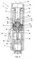
- Fig. 1discloses syringe device 2 comprising a mechanism 4 for preventing setting of a dose which exceeds the amount of a medicament in a reservoir 6.
- the mechanism 4comprises a piston rod 8, a limiter 10 and a driver 12.
- the driveris coupled to a dose setting member (not shown) such that rotation of the dose setting member during dose setting, causes the driver to rotate in the same direction - both when dialling up and down.
- the inner surface 14 of the driver 12has a threaded surface which is adapted to engage a corresponding thread of the outer surface 16 of the limiter 10.
- the limiter 10is locked for rotation in relation to the piston rod 8 by means of groove 18 in the piston rod 8 and a tongue 20 in the limiter 10 (in the figure the tongue is indicated by a dotted line). Due to the grove-tongue arrangement the limiter 10 and the piston rod 8 may move translationally (i.e. up and down in the figure) in relation to each other.
- the limitercomprises a first set of teeth 22 adapted to engage a second set of teeth 24 of the housing 26.
- the function of the teethis to ensure that the dose set does not exceed the amount of a medicament left in the reservoir 6.
- the threads of the inner surface 14 and the outer surface 16comprises a stopping thread which are also used to ensure that that the user cannot set a dose which exceed the amount of a medicament in the reservoir.
- the two systemsare redundant and designed to stop dose setting simultaneously.
- the syringe devicefurther comprises a locking means 28 in the form of a screw, which is used to lock the piston rod 8 for rotation in relation to the housing 26. Due the threaded engagement 30 between the housing 26 and the piston rod 8, rotational locking of said two elements, results in a translational lock.
- the locking meansis in the form of a screw, it is desirable that the tip of the screw engages the piston rod in a root of the thread, such that the crest of the thread is not damaged.
- the limiter 10In the initial state i.e. when the pen is delivered to the user, the limiter 10 is located in proximal end 32 of the piston rod (i.e. the end opposite the needle of the syringe device).
- the userlocks the piston rod for rotation by means of the locking means 28.
- the doseis then set by rotating the driver as indicated by the arrow 34. Due to the relative rotational movement between the piston rod 8 and the driver 12 the limiter 10 moves towards in a distal end 36 of the piston rod.
- the driver, the limiter and the piston rodare locked rotationally in relation to each other such that when a dose is ejected, they all rotate together. Due to the threaded engagement 30 between the housing and the piston rod 8, the rotation of the piston rod causes the piston rod to move in the distal direction. However, due to the grove-tongue between the piston rod and the limiter, the translational movement of the piston rod is not transmitted to the limiter and the driver. Accordingly, the limiter (and the driver) remains in the same longitudinal position.
- the limitermoves closer to the stopping position in which the first and second set of teeth engage and wherein the stopping thread engage. In this position the driver cannot be rotated further, and any torque applied to the dose setting member by the user is transferred from the dose setting member to the driver and via two torque paths.
- the torqueis transferred through the first torque path 38, it is transferred from the driver to the limiter, further through the grove-tongue connection to the piston rod and finally from the piston rod to the housing, due to the rotational locking means 28.
- the torqueis transferred through the second torque path 40 it is transferred from the driver to the limiter, further from the first set of teeth 22 to the second set of teeth 24 of the housing.
- Fig. 2shows the housing 26 comprising the second set of teeth 24 which are adapted to engage the first set of teeth 22 of the housing.
- Each toothmay have a one surface 21 which is substantially parallel with the axial direction of the limiter and another surface 23 which is transverse to said axial direction.
- Fig. 3discloses an alternative to the grove-tongue described in connection with Fig. 1 .
- the piston rod 8has two flat surfaces 39 and due to corresponding flat surfaces 41 of the limiter 10, the limiter and the piston rod are locked for relative rotational movement.
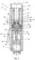
- Fig. 4discloses a syringe device 2 comprising the mechanism 4 described in relation to Fig. 1 .
- the syringe device of Fig. 4further comprises an injection assisting mechanism 42 comprising a spring 44 interconnecting the housing 26 and a first part 46 of a ratchet mechanism 47, which further comprises a second part 48.
- an injection assisting mechanism 42comprising a spring 44 interconnecting the housing 26 and a first part 46 of a ratchet mechanism 47, which further comprises a second part 48.
- the dose setting member 50When the dose setting member 50 is rotated, the rotation is transferred to the driver 12 and the first part 46 of the ratchet mechanism.
- the spring 44is strained whereby potential energy is stored. The stored energy may be released by disengaging the pawl 52 which during dose setting engages the second part 48 of the ratchet mechanism.
- the pawl 52is pivotally connected to the housing and comprises an engaging part 54 and a button part 56.
- the strained spring 44causes the first part 46 to rotate. Due to the engagement between the first part 46 and the second part 48, and due to the grove-tongue connection 49 between the second part 48 and the piston rod 8, the rotation of the first part 46 causes the piston rod to rotate. As described under Fig. 1 the rotation of the piston rod causes the piston rod to move forward.
- Fig. 5discloses the mechanism according to the second general embodiment of the invention. Identical reference numbers refer to identical elements.
- the driver 12is coupled to a dose setting member (not shown) such that rotation of the dose setting member during dose setting, causes the driver to rotate in the same direction - both when dialling up and down.
- the inner surface of the driver 12comprises a groove 58 which is adapted to engage a corresponding radially extending spline 60 of the limiter 10. Accordingly, the driver 12 and the limiter 10 are locked for relative rotational movement, while relative translational movement is possible.
- the limiter 10has a threaded inner surface 62 which engages a corresponding threaded outer surface 64 of the piston rod 8. Accordingly, relative rotation between the piston rod and the driver results in relative translational movement between the limiter and each of the piston rod and the driver.
- the device of Fig. 5does not comprise first and second sets of teeth.
- sets of teethcould have been provided in the same manner as in Fig. 1 .
- the only differenceis that such sets of teeth should have been provided on the surface 66 and on the other, upper side of the limiter as the limiter moves in the direction of the proximal end 32 when a dose is set, as will be described in the following.
- the limiterIn the initial state i.e. when the pen is delivered to the user, the limiter is located in a reference position wherein a surface 61 of the limiter engages a surface 63 of the housing 26. In some embodiments the surfaces 61,63 are spaced apart when the limiter is positioned in the reference position.
- the userlocks the piston rod for rotation by means of the locking means 28.
- the doseis then set by rotating the driver as indicated by arrow 34. Due to the relative rotational movement between the piston rod 8 and the driver 12 the limiter moves towards a proximal end 32 of the piston rod.
- the driver, the limiter and the piston rodare locked rotationally in relation to each other such that, when a dose is ejected, they all rotate together. Due to the threaded engagement 30 between the housing and the piston rod 8, the rotation of the piston rod causes the piston rod to move in the distal direction. Due to the grove-spline connection 59 between the driver and the limiter, the translational movement of the piston rod is not transmitted to the driver. However, due to the threaded connection between the piston rod and the limiter, the limiter will move with the piston rod and arrive at the reference position, i.e. the position it had prior to setting the dose.
- the invention according to the second general embodimentdoes not have the accumulative effect which is seen in connection with the invention according to first general embodiment ( Fig. 1-4 ).
- the limiterreturns to the reference position during ejecting of the set dose.
- Thismay be used to provide a safety mechanism adapted to prevent ejection of a dose exceeding the set dose, this is described in further detail in connection with Fig. 8 .
- Fig. 6discloses a cross-section through the piston rod 8, the limiter 10 and the driver 12.
- the limiter 10is locked for rotational movement relative to the driver 12 due to engagement between the groove 58 and the radially extending spline 60 of the limiter 10.
- Fig. 7discloses a syringe device 2 comprising the mechanism 4 described in relation to Fig. 5 .
- the syringe device of Fig. 6further comprises an injection assisting mechanism 42 comprising a spring 44 interconnecting the housing 26 and a first part 46 of a ratchet mechanism 47, which further comprises a second part 48.
- an injection assisting mechanism 42comprising a spring 44 interconnecting the housing 26 and a first part 46 of a ratchet mechanism 47, which further comprises a second part 48.
- the pawl 52is pivotally connected to the housing and comprises an engaging part 54 and a button part 56.
- the strained spring 44causes the first part 46 to rotate. Due to the engagement between the first part 46 and the second part 48, and due to the grove-tongue connection 49 between the first part 46 and the piston rod 8, the rotation of the first part 46 causes the piston rod to rotate. As described under Fig. 1 the rotation of the piston rod causes the piston rod to move forward.
- the syringe devicecomprises means for preventing ejection of a dose exceeding the set dose.
- Said meanscomprises a dose limiting mechanism and a safety mechanism as will be described in detail below.
- An advantage of the two redundant mechanismsis that if one fails the other may still prevent ejection of a dose exceeding the set dose.
- the embodiment of Fig. 8further comprises an end-of-content mechanism.
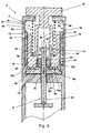
- Fig. 8discloses a syringe device 2 comprising a housing 4 and a piston rod 8.
- the syringe device 2further comprises a dose setting member 50 and a driver 12, which in the figure are combined into one single unit.
- the syringe devicefurther comprises a scale drum 70 for indicating a set dose through a window 72.
- the scale drum 70has a threaded outer surface 74 adapted to engage a corresponding threaded inner surface 76 of the housing.
- the scale drum 70is rotationally retained relative to the driver 12 through a grove-tongue engagement 78.
- the drum scale 70comprises a first stopping surface 80 adapted to engage a second stopping surface 82 of the housing.
- the first stopping surface 80 and the second stopping surface 82constitutes the dose limiting mechanism 84.
- the first stopping surface 80is moved away from the second stopping surface 82 during dose setting and towards each other during dose ejecting. When the two surfaces abut each other, the device is prevented from ejecting the medicament. Thus, a dose larger than the set dose cannot be expelled as the first and second stopping surfaces abut when the set dose has been expelled
- the syringe devicecomprises an ejection assisting system 42 in the form of a pre-strained torsional spring 44 extending between a proximal part 86 of the housing and the driver 12. Accordingly, when the dose setting member 50 is rotated to set a dose, the spring 44 is strained even further.
- the piston rod 8comprises a threaded outer surface 64 adapted to engage a corresponding threaded inner surface 30 of the housing and accordingly rotation of the piston rod relative to the housing causes the piston rod to move translationally in relation to the housing.
- the threaded outer surface 64 of the piston rodalso engages a threaded inner surface 62 of a limiter 10, which in Fig. 8 is positioned in a stopping position wherein a bottom surface 61 of the limiter engages an upper surface 63 of a piston rod guide 88.
- the bottom surface 61 and the upper surface 63constitute the safety mechanism 90.
- An air gapmay be provided between the bottom surface 61 and the upper surface 63 when the limiter is in said stopping position, which allows the limiter and the piston rod to rotate and angel corresponding to a non-lethal dose e.g. 3 IU of insulin, if the dose limiting mechanism 84 fails.
- a non-lethal dosee.g. 3 IU of insulin
- an upper end-of-contend surface 68 of the limiter 10is adapted to engage a lower end-of-contend surface 66 of a T-shaped end part 92 of the piston rod.
- the end-of-contend surfacesare adapted to engage when the set dose correspond to the amount of a medicament remaining in a reservoir (not shown) of the device. Accordingly, the engagement of the end-of-contend surfaces prevents setting of a dose exceeding the amount of a medicament remaining in the reservoir. It will be appreciated that the distance between the end-of-contend surfaces thus corresponds to the amount of the medicament remaining in the reservoir.
- an upper surface 94 of the drum 70may be adapted to engage a lower surface 96 of the housing, when the maximum dose is set.
- the maximum doseis the largest dose which may be set for each ejection (provided that the syringe device comprises the required amount of medicament).
- the maximum dosedoes not correspond to the end-of-content dose which relates the remaining amount of a medicament in the device. Accordingly, as long as the remaining amount of medicament in the device is larger than the maximum dose, the end-of-content surfaces will not abut each other during dose setting, whereas when the remaining amount of medicament in the device is lower than the maximum dose, the maximum dose surfaces may abut each other during dose setting, as the end-of-content surfaces prevents further rotation.
- the limiter 10 and the driver 12are locked for relative rotation by means of grove-tongue engagement 59.
- a relative rotation between the driver 12 and the piston rod 8causes the limiter to move away from the stopping position and towards the t-shaped end part 92 (i.e. upwards in the figure).
- the piston rodis locked for rotation relative to the housing when the piston rod guide 88 is locked for rotation relative to the housing (not shown), as the piston rod guide 88 and the piston rod are locked for relative rotation due to the grove-tongue engagement 98.
- the driver 12 and the piston rod guide 88are interconnected by a two-way ratchet mechanism 100 comprising at least one first retaining member 102 defined by the driver 12 and at least one second retaining member 104 defined by the piston rod guide 88.
- the two-way ratchet mechanismis adapted to allow relative rotational movement between the driver 12 and the piston rod guide 88 during dose setting and to ensure that rotational movement of the driver during dose ejection is transferred to the piston rod guide 88.
- the use of the deviceis as follows. Initially the piston rod guide is locked for rotation relative to the housing. Then the dose setting member is rotated which causes the driver and the drum scale to rotate and the pre-strained spring to be strained even further. At the same time, the limiter moves towards the T-shaped end part. If the user tries to set a dose exceeding the amount of medicament in the device, the limiter abuts the T-shaped end part whereby an even larger dose cannot be set. The dose is ejected by removing the rotational lock between the piston rod guide and the housing, whereby the strained spring forces the driver to rotate. The rotating driver forces the piston rod guide to rotate which again forces the piston rod to rotate. Due to the grove-tongue engagement 44 and the threaded interconnection between the piston rod and the housing, the rotating piston rod is forced to move forward and thus the medicament is expelled from the device.
Landscapes
- Health & Medical Sciences (AREA)
- Vascular Medicine (AREA)
- Engineering & Computer Science (AREA)
- Anesthesiology (AREA)
- Biomedical Technology (AREA)
- Heart & Thoracic Surgery (AREA)
- Hematology (AREA)
- Life Sciences & Earth Sciences (AREA)
- Animal Behavior & Ethology (AREA)
- General Health & Medical Sciences (AREA)
- Public Health (AREA)
- Veterinary Medicine (AREA)
- Infusion, Injection, And Reservoir Apparatuses (AREA)
- Catching Or Destruction (AREA)
- High-Pressure Fuel Injection Pump Control (AREA)
Abstract
Description
- The present invention relates to a mechanism for preventing setting of a dose which exceeds the amount of a medicament in a reservoir in an injection device. In particular, the present invention relates to a mechanism wherein the piston rod forms part of said mechanism, whereby a compact structure may be provided.
- When drugs are to be injected into the human body, it is essential that the dose set by the user is the actual dose injected. If this is not the case, the medicating of the patient is not correct, which in some cases can have serious or even fatal consequences. In order to ensure that the dose selected by a dose setting member does not exceed the remaining amount of medication in a reservoir in a syringe device, an end-of-content mechanism may be provided.
- End-of-content mechanisms are known in the art. One such example may be seen in
WO 01/19434 A1 - Another example may be seen in
WO 2004/007003 A1 . US 5,939,642 disclose an injection device comprising a driver, a nut and a threaded piston rod. During dose setting the nut is rotational screwed up the threaded piston rod and during dosing the nut and the piston rod is brought axial forward the same distance. Once the nut reaches the end of the thread of the threaded piston rod no further dose can be set.- It is an object of a preferred embodiment of the present invention to provide an alternative to the above solution. Especially, it is an object of the present invention to provide a solution which allows an outer surface of a driver to be directly coupled to the inner surface of a drum scale, and thus it is an object of the present invention to provide an end-of-content mechanism which may be positioned in the space defined by the inner walls of a driver.
- The present invention provides an accumulative and a non-accumulative solution to the above problems.
- In the accumulative solution which is described below under a first general embodiment of the invention a limiter is moved stepwise closer to a stopping position wherein the limiter acts together with other elements of the preventing mechanism to ensure that it is not possible to set a dose exceeding the amount of medicament left in a reservoir.
- In the non-accumulative solution which is described under the second general embodiment of the invention the limiter is positioned in the same position prior to dose setting and after dose ejection.
- The present invention relates to a mechanism for preventing setting of a dose which exceeds the amount of a medicament in a reservoir in an injection device, wherein a dose is set by rotating a dose setting member of a dose setting mechanism, the mechanism comprising:
- a piston rod having a threaded outer surface;
- a housing defining a passage for the piston rod, the passage having a threaded inner surface for engagement with the threaded outer surface of the piston rod, the housing being arranged with respect to the piston rod such that rotation of the piston rod in relation to the housing causes the piston rod to be displaced relative to the housing in a longitudinal direction:
- a limiter defining a passage for the piston rod;
- a driver defining a passage for the limiter, the driver being coupled to the dose setting member such that rotation of the dose setting member during dose setting causes the driver to rotate; and
- The mechanism may further comprise a housing defining a passage for the piston rod, the passage may have a threaded inner surface for engament with the threaded outer surface of piston rod, the housing may be arranged with respect to the piston rod such that rotation of the piston rod, in relation to the housing, causes the piston rod to be displaced relative to the housing in a longitudinal direction. The housing may form part of the housing of a syringe device into which the mechanism is integrated.
- The mechanism may comprise a locking means for locking the piston rod against rotation in at least one direction, relative to the housing. Such a locking means may be a screw which may engage or disengage the piston rod. Advantageously, the screw may be arranged such that it engages a root part of the piston rod, whereby the walls of the thread and especially not the crest are not damaged. Alternatively, the locking means may be provided as a pivotable arm, which is operable from an outer surface of the device. The pivotable arm may be movable between an engaging and a non-engaging position, by means of an arm or button accessible from the outer surface of the syringe device.
- The mechanism may comprise a ratchet mechanism interconnecting the driver and the housing. The ratchet mechanism may comprise a first and a second part. The first part may be coupled to the driver while the second part may be coupled to the housing e.g. via the locking means. The ratchet mechanism may be adapted to move in one or two rotational directions.
- In order to assist patients with poor dexterity an ejection assisting system for providing an ejection force for assisting an operator during ejection may be provided. Such a system may comprise a spring which is strained when the dose setting member is rotated during dose setting. The spring may interconnect the housing and the first part of the ratchet e.g. in such a way that it co-extend the piston rod. Accordingly, when the driver is rotated by means of the dose setting member, whereby the first part of the ratchet is rotated, the spring is rotationally strained. The potential energy stored in the strained spring is released by disengaging the locking means whereby the ratchet mechanism is free to move, whereby the strained spring forces the ratchet mechanism to rotate. As the second part of the ratchet mechanism may be locked for rotation in relation to the piston rod, the rotating ratchet mechanism carries the piston rod with it.
- In one embodiment, the spring is pre-strained, such as one revolution, such as two revolutions, such as three revolutions, such as four revolutions, such as five revolutions.
- In the context of the present invention the term "stopping thread" shall be understood as engaging threads of two elements, at least one of which threads prevents a first of the two elements from being rotated beyond a predetermined position relative to a second of the two elements. Normally, said prevention of rotation is caused by engagement of surfaces of each of the two elements.
- In the following a first general embodiment of the invention is described.
- In a FIRST general embodiment the present invention relates to a mechanism for preventing setting of a dose which exceeds the amount of a medicament in a reservoir In an injection device, wherein a dose is set by rotating a dose setting member of a dose setting mechanism, the mechanism comprising:
- a piston rod having a threaded outer surface;
- a limiter defining a passage for the piston rod and being rotationally retained in relation to the piston rod, the limiter having a threaded outer surface;
- a driver defining a passage for the limiter, the passage having a threaded inner surface for engagement with the threaded outer surface of the limiter, the driver being coupled to the dose setting member such that rotation of the dose setting member during dose setting causes the driver to rotate; and
- Rotation of the dose setting member during dose setting causes the driver to rotate. If the direction of rotation of the dose setting member and the driver is the same, the driver and the dose setting member may be made as one single unit. Alternatively, the two elements may be made be two separate elements attached or coupled to each other.
- The direction of the thread of the piston rod and the driver may be opposite i.e. if the piston rod has a right-handed thread, the driver has a left-handed thread and vice versa. This ensures that the dose setting member is rotated back to the same position such that the user may set a dose starting from an initial dose of 0 IU.
- The limiter may comprise a first engaging surface adapted to engage a corresponding second , engaging surface of the driver. In one embodiment the limiter comprises a plurality of first engaging surfaces which are adapted to engage corresponding second engaging surfaces of the driver. In some embodiments the number of first and second engaging surfaces is not identical. As an example there may be provided two first engaging surfaces while there is provided ten second engaging surfaces. Accordingly, the limiter may be locked in relation to each other in ten different positions, but at each position only two first and two second engaging surfaces engage each other.
- The threaded outer surface of the piston rod may comprise the first surface and the threaded inner surface of the driver comprises the second surface. The piston rod and the driver may be arranged such that relative rotational movement may cause the first and the second surface to be brought into engagement, whereby further relative rotational movement is not possible.
- Alternatively, the limiter may comprise a plurality of teeth adapted to engage corresponding teeth of the housing and/or the driver when the limiter is in the stopping position. Accordingly, the teeth of the limiter comprise first engaging surfaces, while the teeth of the housing and/or driver may comprise the second stopping surfaces.
- In one embodiment there is provided both teeth and a stopping thread. An advantage of this is that a larger torque may be transferred from the driver to the limiter, whereby it may be ensured that even when applying a large torque to the dose setting mechanism, a dose which exceeding the actual amount left in the reservoir cannot be set. Such a larger torque may be between 100 and 1000 Nmm, such as 250 Nmm, such as 500 Nmm, such as 750 Nmm.
- In the following a second general embodiment of the invention is described.
- In a SECOND general embodiment the present invention relates to a mechanism for preventing setting of a dose which exceeds the amount of a medicament in a reservoir in an injection device, wherein a dose is set by rotating a dose setting member of a dose setting mechanism, the mechanism comprising:
- a piston rod having a threaded outer surface;
- a limiter defining a passage for the piston rod, the passage having a threaded inner surface for engagement with the threaded outer surface of the piston rod;
- a driver defining a passage for the limiter, the driver being rotationally retained in relation to the limiter, the driver being coupled to the dose setting mechanism such that rotation of the dose setting member during dose setting causes the driver to rotate; and
- As described above the invention according to the second general embodiment of the invention is a non-accumulative solution, wherein the limiter is positioned in the same position (the reference position) prior to dose setting and after dose ejection.
- The limiter may comprise a first engaging surface adapted to engage a corresponding second engaging surface of the piston rod. The engaging surface of the limiter may be an end surface extending in a radial direction of the limiter and facing a corresponding radial surface of a T-shaped piston rod. Accordingly, when the piston rod is rotated relative to the limiter, the two surfaces will abut each other such that the user is prevented from setting a higher dose. In the alternative the threaded outer surface of the piston rod comprises the first surface and the threaded inner surface of the driver comprises the second surface. The two latter surfaces may each define a plane parallel with the axis of the piston rod and the limiter.
- The invention will now be described in further detail with reference to the drawings, in which:
Fig. 1 illustrates a mechanism according to the first general embodiment of the invention,Fig. 2 illustrates teeth of the limiter and the housing according to the first general embodimentFig. 3 illustrates a cross-section through of the piston rod, the limiter and the driver ofFig. 1 ,Fig. 4 illustrates a syringe device with injection assisting means and a mechanism according- to the first general embodiment of the invention,
Fig. 5 illustrates a mechanism according to the second general embodiment of the invention,Fig. 6 illustrates a cross-section through the piston rod, the limiter and the driver ofFig. 2 ,Fig. 7 illustrates a syringe device with injection assisting means and a mechanism according to the second general embodiment, of the invention, andFig. 8 illustrates a syringe device according to the second general embodiment of the invention wherein the limiter is used both as an end-of-content and as a safety mechanism.Fig. 1 disclosessyringe device 2 comprising amechanism 4 for preventing setting of a dose which exceeds the amount of a medicament in areservoir 6. Themechanism 4 comprises apiston rod 8, alimiter 10 and adriver 12. The driver is coupled to a dose setting member (not shown) such that rotation of the dose setting member during dose setting, causes the driver to rotate in the same direction - both when dialling up and down. Theinner surface 14 of thedriver 12 has a threaded surface which is adapted to engage a corresponding thread of theouter surface 16 of thelimiter 10. Moreover, thelimiter 10 is locked for rotation in relation to thepiston rod 8 by means ofgroove 18 in thepiston rod 8 and atongue 20 in the limiter 10 (in the figure the tongue is indicated by a dotted line). Due to the grove-tongue arrangement thelimiter 10 and thepiston rod 8 may move translationally (i.e. up and down in the figure) in relation to each other.- The limiter comprises a first set of
teeth 22 adapted to engage a second set ofteeth 24 of thehousing 26. The function of the teeth is to ensure that the dose set does not exceed the amount of a medicament left in thereservoir 6. Furthermore, the threads of theinner surface 14 and theouter surface 16 comprises a stopping thread which are also used to ensure that that the user cannot set a dose which exceed the amount of a medicament in the reservoir. The two systems are redundant and designed to stop dose setting simultaneously. - The syringe device further comprises a locking means 28 in the form of a screw, which is used to lock the
piston rod 8 for rotation in relation to thehousing 26. Due the threadedengagement 30 between thehousing 26 and thepiston rod 8, rotational locking of said two elements, results in a translational lock. When the locking means is in the form of a screw, it is desirable that the tip of the screw engages the piston rod in a root of the thread, such that the crest of the thread is not damaged. - In the initial state i.e. when the pen is delivered to the user, the
limiter 10 is located inproximal end 32 of the piston rod (i.e. the end opposite the needle of the syringe device). - In order to set a dose the user locks the piston rod for rotation by means of the locking means 28. The dose is then set by rotating the driver as indicated by the
arrow 34. Due to the relative rotational movement between thepiston rod 8 and thedriver 12 thelimiter 10 moves towards in adistal end 36 of the piston rod. - When the desired dose has been set, the driver, the limiter and the piston rod are locked rotationally in relation to each other such that when a dose is ejected, they all rotate together. Due to the threaded
engagement 30 between the housing and thepiston rod 8, the rotation of the piston rod causes the piston rod to move in the distal direction. However, due to the grove-tongue between the piston rod and the limiter, the translational movement of the piston rod is not transmitted to the limiter and the driver. Accordingly, the limiter (and the driver) remains in the same longitudinal position. - It will be appreciated, that during each dose setting the limiter moves closer to the stopping position in which the first and second set of teeth engage and wherein the stopping thread engage. In this position the driver cannot be rotated further, and any torque applied to the dose setting member by the user is transferred from the dose setting member to the driver and via two torque paths. When the torque is transferred through the
first torque path 38, it is transferred from the driver to the limiter, further through the grove-tongue connection to the piston rod and finally from the piston rod to the housing, due to the rotational locking means 28. When the torque is transferred through thesecond torque path 40 it is transferred from the driver to the limiter, further from the first set ofteeth 22 to the second set ofteeth 24 of the housing. By providing a first torque path and a second torque path it is possible to apply a larger torque without breaking the parts of the device e.g. the teeth, and, thus, the risk of user causing damage to the device is reduced. Fig. 2 shows thehousing 26 comprising the second set ofteeth 24 which are adapted to engage the first set ofteeth 22 of the housing. Each tooth may have a onesurface 21 which is substantially parallel with the axial direction of the limiter and anothersurface 23 which is transverse to said axial direction.Fig. 3 discloses an alternative to the grove-tongue described in connection withFig. 1 . In the alternative thepiston rod 8 has twoflat surfaces 39 and due to correspondingflat surfaces 41 of thelimiter 10, the limiter and the piston rod are locked for relative rotational movement.Fig. 4 discloses asyringe device 2 comprising themechanism 4 described in relation toFig. 1 . However, the syringe device ofFig. 4 further comprises aninjection assisting mechanism 42 comprising aspring 44 interconnecting thehousing 26 and afirst part 46 of aratchet mechanism 47, which further comprises asecond part 48. When thedose setting member 50 is rotated, the rotation is transferred to thedriver 12 and thefirst part 46 of the ratchet mechanism. During the rotation of the dose setting member, thespring 44 is strained whereby potential energy is stored. The stored energy may be released by disengaging thepawl 52 which during dose setting engages thesecond part 48 of the ratchet mechanism. Thepawl 52 is pivotally connected to the housing and comprises anengaging part 54 and abutton part 56. When the pawl is disengaged thestrained spring 44 causes thefirst part 46 to rotate. Due to the engagement between thefirst part 46 and thesecond part 48, and due to the grove-tongue connection 49 between thesecond part 48 and thepiston rod 8, the rotation of thefirst part 46 causes the piston rod to rotate. As described underFig. 1 the rotation of the piston rod causes the piston rod to move forward.Fig. 5 discloses the mechanism according to the second general embodiment of the invention. Identical reference numbers refer to identical elements. InFig. 5 thedriver 12 is coupled to a dose setting member (not shown) such that rotation of the dose setting member during dose setting, causes the driver to rotate in the same direction - both when dialling up and down. The inner surface of thedriver 12 comprises agroove 58 which is adapted to engage a corresponding radially extendingspline 60 of thelimiter 10. Accordingly, thedriver 12 and thelimiter 10 are locked for relative rotational movement, while relative translational movement is possible. Furthermore, thelimiter 10 has a threadedinner surface 62 which engages a corresponding threadedouter surface 64 of thepiston rod 8. Accordingly, relative rotation between the piston rod and the driver results in relative translational movement between the limiter and each of the piston rod and the driver.- Unlike
Fig. 1 the device ofFig. 5 does not comprise first and second sets of teeth. However, it will be appreciated that such sets of teeth could have been provided in the same manner as inFig. 1 . The only difference is that such sets of teeth should have been provided on thesurface 66 and on the other, upper side of the limiter as the limiter moves in the direction of theproximal end 32 when a dose is set, as will be described in the following. - In the initial state i.e. when the pen is delivered to the user, the limiter is located in a reference position wherein a
surface 61 of the limiter engages asurface 63 of thehousing 26. In some embodiments thesurfaces - In order to set a dose the user locks the piston rod for rotation by means of the locking means 28. The dose is then set by rotating the driver as indicated by
arrow 34. Due to the relative rotational movement between thepiston rod 8 and thedriver 12 the limiter moves towards aproximal end 32 of the piston rod. - When the desired dose has been set, the driver, the limiter and the piston rod are locked rotationally in relation to each other such that, when a dose is ejected, they all rotate together. Due to the threaded
engagement 30 between the housing and thepiston rod 8, the rotation of the piston rod causes the piston rod to move in the distal direction. Due to the grove-spline connection 59 between the driver and the limiter, the translational movement of the piston rod is not transmitted to the driver. However, due to the threaded connection between the piston rod and the limiter, the limiter will move with the piston rod and arrive at the reference position, i.e. the position it had prior to setting the dose. Accordingly, as described in the aforementioned, the invention according to the second general embodiment does not have the accumulative effect which is seen in connection with the invention according to first general embodiment (Fig. 1-4 ). On the contrary the limiter returns to the reference position during ejecting of the set dose. This may be used to provide a safety mechanism adapted to prevent ejection of a dose exceeding the set dose, this is described in further detail in connection withFig. 8 . - At a point the piston rod arrives in the stopping position wherein a first stopping
thread 66 of thethread 64 of the piston rod engages a second stoppingthread 68 of the limiter. The result is that a set dose may not be increased and any torque applied to the driver is transferred to the limiter due to the grove-spline-connection and further to the piston rod due to the stopping thread and finally from the piston rod to the housing - this is indicated byarrow 38. - As the piston rod is locked in relation to the housing by means of the locking means 28, further rotation of the driver is not possible.
Fig. 6 discloses a cross-section through thepiston rod 8, thelimiter 10 and thedriver 12. Thelimiter 10 is locked for rotational movement relative to thedriver 12 due to engagement between thegroove 58 and theradially extending spline 60 of thelimiter 10.Fig. 7 discloses asyringe device 2 comprising themechanism 4 described in relation toFig. 5 . However, the syringe device ofFig. 6 further comprises aninjection assisting mechanism 42 comprising aspring 44 interconnecting thehousing 26 and afirst part 46 of aratchet mechanism 47, which further comprises asecond part 48. When thedose setting member 50 is rotated, the rotation is transferred to thedriver 12 and thefirst part 46 of the ratchet mechanism. During the rotation of thedose setting member 50, thepre-strained spring 44 is strained even more whereby further potential energy is stored. The stored energy may be released by disengaging thepawl 52 which during dose setting engages thesecond part 48 of the ratchet mechanism. Thepawl 52 is pivotally connected to the housing and comprises anengaging part 54 and abutton part 56. When the pawl is disengaged thestrained spring 44 causes thefirst part 46 to rotate. Due to the engagement between thefirst part 46 and thesecond part 48, and due to the grove-tongue connection 49 between thefirst part 46 and thepiston rod 8, the rotation of thefirst part 46 causes the piston rod to rotate. As described underFig. 1 the rotation of the piston rod causes the piston rod to move forward.- In the embodiment disclosed in
Fig. 8 the syringe device comprises means for preventing ejection of a dose exceeding the set dose. Said means comprises a dose limiting mechanism and a safety mechanism as will be described in detail below. An advantage of the two redundant mechanisms is that if one fails the other may still prevent ejection of a dose exceeding the set dose. The embodiment ofFig. 8 further comprises an end-of-content mechanism. Fig. 8 discloses asyringe device 2 comprising ahousing 4 and apiston rod 8. Thesyringe device 2 further comprises adose setting member 50 and adriver 12, which in the figure are combined into one single unit. The syringe device further comprises ascale drum 70 for indicating a set dose through awindow 72. Thescale drum 70 has a threadedouter surface 74 adapted to engage a corresponding threadedinner surface 76 of the housing. Thescale drum 70 is rotationally retained relative to thedriver 12 through a grove-tongue engagement 78. Thedrum scale 70 comprises a first stoppingsurface 80 adapted to engage a second stoppingsurface 82 of the housing. The first stoppingsurface 80 and the second stoppingsurface 82 constitutes thedose limiting mechanism 84. The first stoppingsurface 80 is moved away from the second stoppingsurface 82 during dose setting and towards each other during dose ejecting. When the two surfaces abut each other, the device is prevented from ejecting the medicament. Thus, a dose larger than the set dose cannot be expelled as the first and second stopping surfaces abut when the set dose has been expelled- The syringe device comprises an
ejection assisting system 42 in the form of a pre-strainedtorsional spring 44 extending between aproximal part 86 of the housing and thedriver 12. Accordingly, when thedose setting member 50 is rotated to set a dose, thespring 44 is strained even further. - The
piston rod 8 comprises a threadedouter surface 64 adapted to engage a corresponding threadedinner surface 30 of the housing and accordingly rotation of the piston rod relative to the housing causes the piston rod to move translationally in relation to the housing. The threadedouter surface 64 of the piston rod also engages a threadedinner surface 62 of alimiter 10, which inFig. 8 is positioned in a stopping position wherein abottom surface 61 of the limiter engages anupper surface 63 of apiston rod guide 88. Thebottom surface 61 and theupper surface 63 constitute thesafety mechanism 90. An air gap may be provided between thebottom surface 61 and theupper surface 63 when the limiter is in said stopping position, which allows the limiter and the piston rod to rotate and angel corresponding to a non-lethal dose e.g. 3 IU of insulin, if thedose limiting mechanism 84 fails. - Moreover, an upper end-of-contend
surface 68 of thelimiter 10 is adapted to engage a lower end-of-contendsurface 66 of a T-shapedend part 92 of the piston rod. The end-of-contend surfaces are adapted to engage when the set dose correspond to the amount of a medicament remaining in a reservoir (not shown) of the device. Accordingly, the engagement of the end-of-contend surfaces prevents setting of a dose exceeding the amount of a medicament remaining in the reservoir. It will be appreciated that the distance between the end-of-contend surfaces thus corresponds to the amount of the medicament remaining in the reservoir. - Moreover, an
upper surface 94 of thedrum 70 may be adapted to engage alower surface 96 of the housing, when the maximum dose is set. The maximum dose is the largest dose which may be set for each ejection (provided that the syringe device comprises the required amount of medicament). The maximum dose does not correspond to the end-of-content dose which relates the remaining amount of a medicament in the device. Accordingly, as long as the remaining amount of medicament in the device is larger than the maximum dose, the end-of-content surfaces will not abut each other during dose setting, whereas when the remaining amount of medicament in the device is lower than the maximum dose, the maximum dose surfaces may abut each other during dose setting, as the end-of-content surfaces prevents further rotation. - The
limiter 10 and thedriver 12 are locked for relative rotation by means of grove-tongue engagement 59. Thus, when the piston rod is locked for rotation relative to the housing, a relative rotation between thedriver 12 and thepiston rod 8 causes the limiter to move away from the stopping position and towards the t-shaped end part 92 (i.e. upwards in the figure). The piston rod is locked for rotation relative to the housing when thepiston rod guide 88 is locked for rotation relative to the housing (not shown), as thepiston rod guide 88 and the piston rod are locked for relative rotation due to the grove-tongue engagement 98. - The
driver 12 and thepiston rod guide 88 are interconnected by a two-way ratchet mechanism 100 comprising at least onefirst retaining member 102 defined by thedriver 12 and at least onesecond retaining member 104 defined by thepiston rod guide 88. The two-way ratchet mechanism is adapted to allow relative rotational movement between thedriver 12 and thepiston rod guide 88 during dose setting and to ensure that rotational movement of the driver during dose ejection is transferred to thepiston rod guide 88. - The use of the device is as follows. Initially the piston rod guide is locked for rotation relative to the housing. Then the dose setting member is rotated which causes the driver and the drum scale to rotate and the pre-strained spring to be strained even further. At the same time, the limiter moves towards the T-shaped end part. If the user tries to set a dose exceeding the amount of medicament in the device, the limiter abuts the T-shaped end part whereby an even larger dose cannot be set. The dose is ejected by removing the rotational lock between the piston rod guide and the housing, whereby the strained spring forces the driver to rotate. The rotating driver forces the piston rod guide to rotate which again forces the piston rod to rotate. Due to the grove-
tongue engagement 44 and the threaded interconnection between the piston rod and the housing, the rotating piston rod is forced to move forward and thus the medicament is expelled from the device.
Claims (11)
- A mechanism (4) for preventing setting of a dose which exceeds the amount of a medicament in a reservoir (6) in an injection device, wherein a dose is set by rotating a dose setting member (50) of a dose setting mechanism, the mechanism comprising:- a piston rod (8) having a threaded outer surface (64);- a housing (26) defining a passage for the piston rod (8), the passage having a threaded inner surface (30) for engagement with the threaded outer surface (64) of the piston rod (8), the housing (26) being arranged with respect to the piston rod (8) such that rotation of the piston rod (8) in relation to the housing (26) causes the piston rod (8) to be displaced relative to the housing (26) in a longitudinal direction;- a limiter (10) defining a passage for the piston rod (8);- a driver (12) defining a passage for the limiter (10), the driver (12) being coupled to the dose setting member (50) such that rotation of the dose setting member (50) during dose setting causes the driver (12) to rotate; andwherein the limiter (10) is coupled to the driver (12) and the piston rod (8) such that relative rotation between the driver (12) and the piston rod (8) during dose setting causes the limiter (10) to move towards a stopping position wherein the limiter (10) prevents setting of a dose which exceeds the amount of a medicament in a reservoir (6) in the injection device.
- A mechanism according to claim 1, further comprising a locking means (28, 54) for locking the piston rod (8) against rotation in at least one direction relative to the housing (26).
- A mechanism according to any of the preceding claims, wherein:- the limiter (10) has a threaded outer surface (16) and is rotationally retained in relation to the piston rod (8); and- the passage of the driver (12) has a threaded inner surface (14) for engagement with the threaded outer surface (16) of the limiter (10).
- A mechanism according to any of the preceding claims, wherein the limiter (10) comprises a first engaging surface (61) adapted to engage a corresponding second engaging surface (63) of the driver (12).
- A mechanism according to any of the preceding claims, wherein the limiter (10) comprises a plurality of teeth (22) adapted to engage corresponding teeth (24) of the housing (26) and/or the driver (12) when the limiter (10) is in the stopping position.
- A mechanism according to any of claims 1-2, wherein:- the passage of the limiter has a threaded inner surface (62) for engagement with the threaded outer surface (64) of the piston rod (8); and- the driver (12) is rotationally retained in relation to the limiter (10).
- A mechanism according to any of claims 1-2 or 6, wherein the limiter (10) comprises a first engaging surface (68) adapted to engage a corresponding second engaging surface (66) of the piston rod (8).
- A mechanism according to any of the preceding claims, further comprising a ratchet mechanism (47, 100) interconnecting the driver (12) and the housing (26).
- A mechanism according to claim 8, wherein the ratchet mechanism (47, 100) comprises a first and a second part, the first part (46, 104) being coupled to the driver (12) and the second part (48) being adapted to be locked for rotation relative to the housing (26) by means of the locking means (54).
- A mechanism according to any of claims 8 or 9, further comprising an ejection assisting system (42) for providing an ejection force for assisting an operator during ejection.
- A syringe device according to claim 10, wherein the ejection assisting system (42) comprises a spring (44) which is strained when the dose setting member (50) is rotated during dose setting.
Priority Applications (2)
| Application Number | Priority Date | Filing Date | Title |
|---|---|---|---|
| EP06754730.7AEP1909870B2 (en) | 2005-07-27 | 2006-07-17 | Dose mechanism for an injection device for limiting a dose setting corresponding to the amount of medicament left |
| PL06754730.7TPL1909870T5 (en) | 2005-07-27 | 2006-07-17 | Dose mechanism for an injection device for limiting a dose setting corresponding to the amount of medicament left |
Applications Claiming Priority (3)
| Application Number | Priority Date | Filing Date | Title |
|---|---|---|---|
| EP05016291 | 2005-07-27 | ||
| EP06754730.7AEP1909870B2 (en) | 2005-07-27 | 2006-07-17 | Dose mechanism for an injection device for limiting a dose setting corresponding to the amount of medicament left |
| PCT/EP2006/007004WO2007017052A1 (en) | 2005-07-27 | 2006-07-17 | Dose mechanism for an injection device for limiting a dose setting corresponding to the amount of medicament left |
Publications (3)
| Publication Number | Publication Date |
|---|---|
| EP1909870A1 EP1909870A1 (en) | 2008-04-16 |
| EP1909870B1true EP1909870B1 (en) | 2011-03-02 |
| EP1909870B2 EP1909870B2 (en) | 2016-01-20 |
Family
ID=35448209
Family Applications (1)
| Application Number | Title | Priority Date | Filing Date |
|---|---|---|---|
| EP06754730.7AActiveEP1909870B2 (en) | 2005-07-27 | 2006-07-17 | Dose mechanism for an injection device for limiting a dose setting corresponding to the amount of medicament left |
Country Status (10)
| Country | Link |
|---|---|
| US (2) | US8920383B2 (en) |
| EP (1) | EP1909870B2 (en) |
| JP (1) | JP4827922B2 (en) |
| CN (1) | CN101227943B (en) |
| AT (1) | ATE499962T1 (en) |
| DE (1) | DE602006020453D1 (en) |
| DK (1) | DK1909870T4 (en) |
| ES (1) | ES2361563T5 (en) |
| PL (1) | PL1909870T5 (en) |
| WO (1) | WO2007017052A1 (en) |
Cited By (8)
| Publication number | Priority date | Publication date | Assignee | Title |
|---|---|---|---|---|
| US9421334B2 (en) | 2011-03-16 | 2016-08-23 | Becton, Dickinson And Company | Multiple use disposable injection pen |
| US10092705B2 (en) | 2013-04-10 | 2018-10-09 | Sanofi | Injection device |
| US10220153B2 (en) | 2013-09-03 | 2019-03-05 | Sanofi | Pen type drug injection device with dose limiting nut to prevent setting of a dose higher than the amount of drug remaining |
| EP2825227B1 (en) | 2012-03-15 | 2019-05-01 | Becton, Dickinson and Company | Multiple use disposable injection pen |
| US10286155B2 (en) | 2013-09-03 | 2019-05-14 | Sanofi | Pen-type drug injection device with dose setting and re-setting mechanism |
| WO2020227104A1 (en)* | 2019-05-03 | 2020-11-12 | Carefusion 303, Inc. | Syringe with priming mechanism |
| US11577029B2 (en) | 2012-03-15 | 2023-02-14 | Becton, Dickinson And Company | Multiple use disposable injection pen |
| US12350474B2 (en) | 2011-03-16 | 2025-07-08 | Becton, Dickinson And Company | Multiple use disposable injection pen |
Families Citing this family (133)
| Publication number | Priority date | Publication date | Assignee | Title |
|---|---|---|---|---|
| DE102005023823B4 (en)† | 2005-05-24 | 2022-11-17 | Tecpharma Licensing Ag | Dosing device for an injection device and injection device with such a dosing device |
| PL1909871T5 (en) | 2005-07-27 | 2014-05-30 | Novo Nordisk As | Injection device with dose limiting mechanism and additional safety mechanism |
| US8920383B2 (en) | 2005-07-27 | 2014-12-30 | Novo Nordisk A/S | Dose mechanism for an injection device for limiting a dose setting corresponding to the amount of medicament left |
| EP2091598B1 (en)* | 2006-12-15 | 2012-07-11 | Novo Nordisk A/S | A medical delivery system comprising a container and a dosing assembly with radially moving fastening means |
| WO2008074897A1 (en)* | 2006-12-21 | 2008-06-26 | Novo Nordisk A/S | A syringe device |
| EP2164544A1 (en)* | 2007-07-06 | 2010-03-24 | Novo Nordisk A/S | Automatic injection device |
| BRPI0817907B8 (en) | 2007-10-02 | 2021-06-22 | Lamodel Ltd | apparatus for administering a substance to an individual |
| US9345836B2 (en) | 2007-10-02 | 2016-05-24 | Medimop Medical Projects Ltd. | Disengagement resistant telescoping assembly and unidirectional method of assembly for such |
| US10420880B2 (en) | 2007-10-02 | 2019-09-24 | West Pharma. Services IL, Ltd. | Key for securing components of a drug delivery system during assembly and/or transport and methods of using same |
| US7967795B1 (en) | 2010-01-19 | 2011-06-28 | Lamodel Ltd. | Cartridge interface assembly with driving plunger |
| US9656019B2 (en) | 2007-10-02 | 2017-05-23 | Medimop Medical Projects Ltd. | Apparatuses for securing components of a drug delivery system during transport and methods of using same |
| DK3260145T3 (en)* | 2008-04-09 | 2020-02-17 | Hoffmann La Roche | Fluid level sensor for a modular, skin adhesive medical fluid delivery system |
| RU2496528C2 (en) | 2008-05-02 | 2013-10-27 | Санофи-Авентис Дойчланд Гмбх | Drug feeder |
| US8187233B2 (en) | 2008-05-02 | 2012-05-29 | Sanofi-Aventis Deutschland Gmbh | Medication delivery device |
| US8647309B2 (en)* | 2008-05-02 | 2014-02-11 | Sanofi-Aventis Deutschland Gmbh | Medication delivery device |
| US12097357B2 (en) | 2008-09-15 | 2024-09-24 | West Pharma. Services IL, Ltd. | Stabilized pen injector |
| US9393369B2 (en) | 2008-09-15 | 2016-07-19 | Medimop Medical Projects Ltd. | Stabilized pen injector |
| CA2743571C (en)* | 2008-11-17 | 2018-01-02 | Becton, Dickinson And Company | Additive force device for drug delivery pen for intradermal medication injection |
| US9623187B2 (en) | 2009-06-01 | 2017-04-18 | Sanofi-Aventis Deutschland Gmbh | Resettable drug delivery device |
| US9457150B2 (en) | 2009-06-01 | 2016-10-04 | Sanofi-Aventis Deutschland Gmbh | Biasing mechanism for a drug delivery device |
| US9125994B2 (en) | 2009-06-01 | 2015-09-08 | Sanofi—Aventis Deutschland GmbH | Drug delivery device with dose dial sleeve rotational stop |
| US8585656B2 (en) | 2009-06-01 | 2013-11-19 | Sanofi-Aventis Deutschland Gmbh | Dose setting mechanism for priming a drug delivery device |
| US8672896B2 (en) | 2009-06-01 | 2014-03-18 | Sanofi-Aventis Deutschland Gmbh | Inner housing for a drug delivery device |
| US9345840B2 (en) | 2009-06-01 | 2016-05-24 | Sanofi-Aventis Deutschland Gmbh | Drug delivery dose setting mechanism with variable maximum dose |
| US9108007B2 (en) | 2009-06-01 | 2015-08-18 | Sanofi-Aventis Deutschland Gmbh | Spindle and bearing combination and drug delivery device |
| US8974423B2 (en) | 2009-06-01 | 2015-03-10 | Sanofi-Aventis Deutschland Gmbh | Resettable drug delivery device |
| US10034982B2 (en) | 2009-06-01 | 2018-07-31 | Sanofi-Aventis Deutschland Gmbh | Spindle for a drug delivery device |
| US9238106B2 (en) | 2009-06-01 | 2016-01-19 | Sanofi-Aventis Deutschland Gmbh | Dose setting mechanism for priming a drug delivery device |
| US8728043B2 (en) | 2009-06-01 | 2014-05-20 | Sanofi-Aventis Deutschland Gmbh | Drive mechanism for a drug delivery device |
| US9950116B2 (en) | 2009-06-01 | 2018-04-24 | Sanofi-Aventis Deutschland Gmbh | Dose setting mechanism for priming a drug delivery device |
| US9463283B2 (en) | 2009-06-01 | 2016-10-11 | Sanofi-Aventis Deutschland Gmbh | Dosing mechanism for a drug deliver device |
| US9199040B2 (en)* | 2009-06-01 | 2015-12-01 | Sanofi-Aventis Deutschland Gmbh | Drug delivery device last dose lock-out mechanism |
| US8257319B2 (en) | 2009-06-01 | 2012-09-04 | Sanofi-Aventis Deutschland Gmbh | Drug delivery device inner housing having helical spline |
| TWI530306B (en) | 2009-06-02 | 2016-04-21 | 賽諾菲阿凡提斯德意志有限公司 | Drug delivery device assembly and drug delivery device |
| EP2266647A1 (en)* | 2009-06-25 | 2010-12-29 | Sanofi-Aventis Deutschland GmbH | Drive mechanism for drug delivery device |
| CA2771273A1 (en) | 2009-08-27 | 2011-03-03 | Sanofi-Aventis Deutschland Gmbh | Housing component for a drug delivery device |
| US10071196B2 (en) | 2012-05-15 | 2018-09-11 | West Pharma. Services IL, Ltd. | Method for selectively powering a battery-operated drug-delivery device and device therefor |
| US8157769B2 (en) | 2009-09-15 | 2012-04-17 | Medimop Medical Projects Ltd. | Cartridge insertion assembly for drug delivery system |
| US10071198B2 (en) | 2012-11-02 | 2018-09-11 | West Pharma. Servicees IL, Ltd. | Adhesive structure for medical device |
| GB0918145D0 (en)* | 2009-10-16 | 2009-12-02 | Owen Mumford Ltd | Injector apparatus |
| ES2749395T3 (en) | 2009-11-20 | 2020-03-20 | Becton Dickinson Co | Injection device without the need for a gear |
| ES2909887T3 (en) | 2009-12-01 | 2022-05-10 | Becton Dickinson Co | Injection pen with automatic return and last dose control |
| FR2953415B1 (en)* | 2009-12-09 | 2012-12-28 | Primequal Sa | EJECTION DEVICE FOR EJECTING LOW DOSES |
| US8348898B2 (en) | 2010-01-19 | 2013-01-08 | Medimop Medical Projects Ltd. | Automatic needle for drug pump |
| EP2569031B1 (en) | 2010-05-10 | 2017-10-11 | Medimop Medical Projects Ltd. | Low volume accurate injector |
| EP2452711A1 (en)* | 2010-11-12 | 2012-05-16 | Sanofi-Aventis Deutschland GmbH | Drive mechanism for a drug delivery device and drug delivery device |
| EP2452712A1 (en) | 2010-11-12 | 2012-05-16 | Sanofi-Aventis Deutschland GmbH | Drive mechanism for a drug delivery device and drug delivery device |
| USD702834S1 (en) | 2011-03-22 | 2014-04-15 | Medimop Medical Projects Ltd. | Cartridge for use in injection device |
| JP5922760B2 (en)* | 2011-04-05 | 2016-05-24 | エス・ホー・エル・グループ・アクチボラゲットShl Group Ab | Drug delivery device having locking mechanism with lever |
| US9732851B2 (en) | 2011-09-06 | 2017-08-15 | Novo Nordisk A/S | Piston rod foot |
| US9101718B2 (en)* | 2011-09-06 | 2015-08-11 | Novo Nordisk A/S | Piston rod foot |
| US10328211B2 (en)* | 2011-12-08 | 2019-06-25 | Unl Holdings Llc | Automatic self-dispensing accurate dose drug delivery syringes |
| WO2015047758A2 (en)* | 2013-09-13 | 2015-04-02 | Unitract Syringe Pty Ltd | Automatic self-dispensing accurate dose drug delivery syringes |
| WO2013127876A1 (en) | 2012-02-29 | 2013-09-06 | Tecpharma Licensing Ag | Injection device with improved piston rod drive |
| US9072827B2 (en) | 2012-03-26 | 2015-07-07 | Medimop Medical Projects Ltd. | Fail safe point protector for needle safety flap |
| WO2013149769A1 (en) | 2012-04-05 | 2013-10-10 | Tecpharma Licensing Ag | Injection device with improved piston rod drive |
| ES2623081T3 (en)* | 2012-04-17 | 2017-07-10 | Carebay Europe Ltd | Medication Administration Device |
| WO2014005807A1 (en) | 2012-07-06 | 2014-01-09 | Carebay Europe Ltd | Medicament delivery device |
| WO2014005808A1 (en)* | 2012-07-06 | 2014-01-09 | Carebay Europe Ltd | Medicament delivery device |
| EP2698179A1 (en)* | 2012-08-14 | 2014-02-19 | Sanofi-Aventis Deutschland GmbH | Injection device |
| ES2637229T3 (en)* | 2012-08-29 | 2017-10-11 | Unitract Syringe Pty Ltd | Controlled drive mechanisms for medication delivery pumps |
| WO2014061339A1 (en)* | 2012-10-17 | 2014-04-24 | 凸版印刷株式会社 | Operating tool for fluid injector using multi microneedle device |
| US9421323B2 (en) | 2013-01-03 | 2016-08-23 | Medimop Medical Projects Ltd. | Door and doorstop for portable one use drug delivery apparatus |
| PL2950853T3 (en) | 2013-02-01 | 2017-09-29 | Novo Nordisk A/S | A non-axial working end-of content mechanism and an injection device comprising the same |
| WO2014162439A1 (en)* | 2013-04-01 | 2014-10-09 | テルモ株式会社 | Syringe |
| AR095798A1 (en)* | 2013-04-10 | 2015-11-11 | Sanofi Sa | INJECTION DEVICE |
| DK2983742T3 (en)* | 2013-04-10 | 2019-09-09 | Sanofi Sa | HANDLED PHARMACEUTICAL INJECTION DEVICE AND LIMITING DOSAGE ADMINISTRATION THEREOF |
| CN105102022B (en)* | 2013-04-10 | 2019-02-01 | 赛诺菲 | Driving mechanism for medicine delivery device |
| EP2983768A1 (en) | 2013-04-10 | 2016-02-17 | Sanofi | Drive mechanism of a drug delivery device |
| CN105163778B (en)* | 2013-04-10 | 2019-03-15 | 赛诺菲 | Limiters mechanisms and injection device with the limiters mechanisms |
| US9011164B2 (en) | 2013-04-30 | 2015-04-21 | Medimop Medical Projects Ltd. | Clip contact for easy installation of printed circuit board PCB |
| CN104129567B (en)* | 2013-04-30 | 2018-08-03 | 麦迪莫普医疗工程有限公司 | The method and related system of the component of fixed drug transport system |
| JP6490057B2 (en)* | 2013-05-16 | 2019-03-27 | サノフィ−アベンティス・ドイチュラント・ゲゼルシャフト・ミット・ベシュレンクテル・ハフツング | Drug delivery device assembly and drug delivery device |
| EP2999504A1 (en) | 2013-05-21 | 2016-03-30 | Novo Nordisk A/S | Drug delivery device with piston rod coupling |
| JP6456928B2 (en) | 2013-06-04 | 2019-01-23 | ノボ・ノルデイスク・エー/エス | Torsion spring type injection device having administration end mechanism |
| WO2015007808A1 (en)* | 2013-07-17 | 2015-01-22 | Sanofi | Drive assembly for a drug delivery device |
| EP2829292B1 (en) | 2013-07-22 | 2017-11-01 | TecPharma Licensing AG | Drive and dosing device having a limiting element for preventing the adjustment of a dose higher than available |
| EP2829290A1 (en) | 2013-07-25 | 2015-01-28 | Sanofi-Aventis Deutschland GmbH | Drive unit for a drug delivery device |
| JP6595476B2 (en)* | 2013-09-03 | 2019-10-23 | サノフイ | Drive mechanism for a drug delivery device |
| EP3041535B1 (en)* | 2013-09-03 | 2019-01-30 | Sanofi | Drive mechanism for a drug delivery device |
| DK3043842T3 (en)* | 2013-09-10 | 2019-02-18 | Sanofi Sa | DRIVE MECHANISM FOR A PHARMACEUTICAL ADMINISTRATION DEVICE |
| RU2680922C2 (en) | 2013-09-23 | 2019-02-28 | Санофи-Авентис Дойчланд Гмбх | Assembly for drug delivery device and drug delivery device |
| CN105636624B (en)* | 2013-10-16 | 2019-07-26 | 诺和诺德股份有限公司 | Drug delivery device with braking mechanism |
| WO2015145294A1 (en) | 2014-03-25 | 2015-10-01 | Wockhardt Limited | Fluid delivery pen with final dose stop and improved dose setting features |
| EP3151764B1 (en)* | 2014-06-09 | 2023-02-01 | Cook Medical Technologies LLC | Screw-driven handles and systems for fiducial deployment |
| WO2016091554A1 (en)* | 2014-12-12 | 2016-06-16 | Carebay Europe Ltd | Dose setting mechanism and medicament delivery device comprising the dose setting mechanism |
| CN107427645B (en) | 2015-03-27 | 2021-05-25 | 诺和诺德股份有限公司 | Deformable piston gasket |
| US10293120B2 (en) | 2015-04-10 | 2019-05-21 | West Pharma. Services IL, Ltd. | Redundant injection device status indication |
| EP3093035A1 (en) | 2015-05-13 | 2016-11-16 | Sanofi-Aventis Deutschland GmbH | Injection device for delivery of a liquid medicament |
| US10149943B2 (en) | 2015-05-29 | 2018-12-11 | West Pharma. Services IL, Ltd. | Linear rotation stabilizer for a telescoping syringe stopper driverdriving assembly |
| CN113181477B (en) | 2015-06-04 | 2023-07-14 | 麦迪麦珀医疗工程有限公司 | Cartridge insertion for drug delivery device |
| US10426196B2 (en)* | 2015-06-09 | 2019-10-01 | Gofire, Inc. | Portable vaporizer for dosing concentrate material |
| EP3106192A1 (en) | 2015-06-17 | 2016-12-21 | TecPharma Licensing AG | Dose setting and dose limiting mechanism for an injection device and method for programming the dose limitation |
| CN107787237B (en) | 2015-07-01 | 2021-02-02 | 诺和诺德股份有限公司 | Drug delivery device |
| CN107787234B (en) | 2015-07-01 | 2021-03-12 | 诺和诺德股份有限公司 | Piston washer for a drug delivery device and drug delivery device incorporating such a piston washer |
| US10576207B2 (en) | 2015-10-09 | 2020-03-03 | West Pharma. Services IL, Ltd. | Angled syringe patch injector |
| US10086145B2 (en) | 2015-09-22 | 2018-10-02 | West Pharma Services Il, Ltd. | Rotation resistant friction adapter for plunger driver of drug delivery device |
| US9987432B2 (en) | 2015-09-22 | 2018-06-05 | West Pharma. Services IL, Ltd. | Rotation resistant friction adapter for plunger driver of drug delivery device |
| WO2017060426A1 (en) | 2015-10-09 | 2017-04-13 | Novo Nordisk A/S | Drug delivery device with slim drive mechanism |
| US11318254B2 (en) | 2015-10-09 | 2022-05-03 | West Pharma. Services IL, Ltd. | Injector needle cap remover |
| PL227678B1 (en) | 2015-12-22 | 2018-01-31 | Copernicus Spolka Z Ograniczona Odpowiedzialnoscia | Control and drive system for the device intended for injection and the device for making injections equipped with such a system |
| EP3711793B1 (en) | 2016-01-21 | 2021-12-01 | West Pharma Services IL, Ltd. | A method of connecting a cartridge to an automatic injector |
| JP6885960B2 (en) | 2016-01-21 | 2021-06-16 | ウェスト ファーマ サービシーズ イスラエル リミテッド | Drug delivery device with visual indicators |
| US10646643B2 (en) | 2016-01-21 | 2020-05-12 | West Pharma. Services IL, Ltd. | Needle insertion and retraction mechanism |
| WO2017134131A1 (en) | 2016-02-02 | 2017-08-10 | Novo Nordisk A/S | A hypocycloid end-of-content mechanism |
| CH712146A2 (en) | 2016-02-23 | 2017-08-31 | Tecpharma Licensing Ag | Injection device with an actuator mounted distally of a dosage setting member for triggering the product distribution. |
| WO2017158033A1 (en) | 2016-03-15 | 2017-09-21 | Sanofi | Dosing mechanism for multi-shot injection device comprising flexible ratchet element |
| US11389597B2 (en) | 2016-03-16 | 2022-07-19 | West Pharma. Services IL, Ltd. | Staged telescopic screw assembly having different visual indicators |
| US10376647B2 (en) | 2016-03-18 | 2019-08-13 | West Pharma. Services IL, Ltd. | Anti-rotation mechanism for telescopic screw assembly |
| CN109310831B (en) | 2016-06-02 | 2021-11-23 | 西医药服务以色列有限公司 | Three position needle retraction |
| PL3108914T3 (en) | 2016-07-07 | 2019-08-30 | Copernicus Sp. Z O.O. | Injection device for delivering a defined number of equal doses of a liquid substance |
| JP7059251B2 (en) | 2016-08-01 | 2022-04-25 | ウェスト ファーマ サービシーズ イスラエル リミテッド | A spring that prevents the door from closing halfway |
| US11338090B2 (en) | 2016-08-01 | 2022-05-24 | West Pharma. Services IL, Ltd. | Anti-rotation cartridge pin |
| GB201615439D0 (en) | 2016-09-12 | 2016-10-26 | Norton Healthcare Ltd | Dose setting mechanism |
| GB201615442D0 (en) | 2016-09-12 | 2016-10-26 | Norton Healthcare Ltd | Dose setting mechanism |
| GB201615455D0 (en) | 2016-09-12 | 2016-10-26 | Norton Healthcare Ltd | Last dose protection |
| EP3515408A1 (en) | 2016-09-23 | 2019-07-31 | Delpor, Inc. | Stable compositions for incretin mimetic compounds |
| EP3548119B1 (en) | 2016-12-01 | 2020-11-18 | Novo Nordisk A/S | Drug delivery device with clutch feature |
| US10589029B2 (en)* | 2016-12-29 | 2020-03-17 | ChitoTech (Keifiat Tolid Takapoo) | Adjustable needle-free injector |
| EP3348298A1 (en) | 2017-01-16 | 2018-07-18 | Novo Nordisk A/S | Drug delivery device with rotationally geared piston rod driver |
| CN110198749B (en) | 2017-01-25 | 2021-11-09 | 诺和诺德股份有限公司 | Prefilled fill device with clean room |
| EP3630226A1 (en) | 2017-05-30 | 2020-04-08 | West Pharma. Services Il, Ltd. | Modular drive train for wearable injector |
| US10688247B2 (en)* | 2017-07-13 | 2020-06-23 | Haselmeier Ag | Injection device with flexible dose selection |
| PL232651B1 (en) | 2017-07-18 | 2019-07-31 | Copernicus Spolka Z Ograniczona Odpowiedzialnoscia | Coupling with locking system for the medical injecting device |
| US11612694B2 (en)* | 2017-07-21 | 2023-03-28 | Becton Dickinson France | Assisted injection device for injecting a composition contained in a medical container with reduced efforts |
| FR3072297B1 (en)* | 2017-10-17 | 2023-05-12 | Edix Sa | MANUAL INJECTION DEVICE |
| JP7402799B2 (en) | 2017-12-22 | 2023-12-21 | ウェスト ファーマ サービシーズ イスラエル リミテッド | Syringes available with different cartridge sizes |
| US11969583B2 (en) | 2018-07-17 | 2024-04-30 | Medmix Switzerland Ag | Injection device with dose interruption fail safe |
| CN112955198B (en) | 2018-10-30 | 2023-07-28 | 诺和诺德股份有限公司 | Torsion spring actuated injection unit |
| US11110227B2 (en) | 2018-11-09 | 2021-09-07 | Cheryl Muise | Method and apparatus for injecting fluids |
| CN110269977A (en)* | 2019-05-14 | 2019-09-24 | 江苏德尔福医疗器械有限公司 | Dosage is adjustable injection pen |
| RU2762040C1 (en)* | 2020-11-06 | 2021-12-15 | СВИ Коммуникатионс-унд Компутер ГмбХ | System for combining digital streams and method for combining digital streams (variants) |
| IL312672A (en) | 2021-11-10 | 2024-07-01 | I2O Therapeutics Inc | Ionic liquid compositions |
Family Cites Families (36)
| Publication number | Priority date | Publication date | Assignee | Title |
|---|---|---|---|---|
| IE52621B1 (en) | 1981-02-12 | 1988-01-06 | Turner Robert Charles | Dose metering plunger devices for use with syringes |
| WO1987002895A1 (en) | 1985-11-08 | 1987-05-21 | Disetronic Ag | Injection instrument |
| GB8713810D0 (en)* | 1987-06-12 | 1987-07-15 | Hypoguard Uk Ltd | Measured dose dispensing device |
| GB8809115D0 (en)* | 1988-04-18 | 1988-05-18 | Turner R C | Syringes |
| DK175491D0 (en) | 1991-10-18 | 1991-10-18 | Novo Nordisk As | APPARATUS |
| ATE225197T1 (en)* | 1994-05-30 | 2002-10-15 | B D Medico S A R L | INJECTION DEVICE |
| JP3568959B2 (en)* | 1995-03-07 | 2004-09-22 | イーライ・リリー・アンド・カンパニー | Reusable dosing device |
| US5921966A (en) | 1997-08-11 | 1999-07-13 | Becton Dickinson And Company | Medication delivery pen having an improved clutch assembly |
| CZ297361B6 (en) | 1998-01-30 | 2006-11-15 | Novo Nordisk A/S | Injection syringe |
| US6221053B1 (en) | 1998-02-20 | 2001-04-24 | Becton, Dickinson And Company | Multi-featured medication delivery pen |
| US6248095B1 (en) | 1998-02-23 | 2001-06-19 | Becton, Dickinson And Company | Low-cost medication delivery pen |
| DE19900792C1 (en) | 1999-01-12 | 2000-06-15 | Disetronic Licensing Ag | Injection unit forming part of e.g. pen-type self-injection syringe has continuous dosing stop in spiral form with constant pitch ensuring close fine control and accuracy in use |
| TW453884B (en)* | 1999-09-16 | 2001-09-11 | Novo Nordisk As | Dose setting limiter |
| US6569123B2 (en)* | 1999-10-14 | 2003-05-27 | Becton, Dickinson And Company | Prefillable intradermal injector |
| US6585698B1 (en)* | 1999-11-01 | 2003-07-01 | Becton, Dickinson & Company | Electronic medical delivery pen having a multifunction actuator |
| US6663602B2 (en)* | 2000-06-16 | 2003-12-16 | Novo Nordisk A/S | Injection device |
| US6899699B2 (en)* | 2001-01-05 | 2005-05-31 | Novo Nordisk A/S | Automatic injection device with reset feature |
| ES2365807T3 (en)* | 2001-05-16 | 2011-10-11 | ELI LILLY & COMPANY | MEDICATION INJECTOR DEVICE WITH MOTOR ASSEMBLY THAT FACILITATES REARME. |
| DE10163328B4 (en) | 2001-07-30 | 2005-08-11 | Tecpharma Licensing Ag | Administration device with anti-rotation device |
| DE20209051U1 (en) | 2001-12-21 | 2003-04-24 | Disetronic Licensing Ag, Burgdorf | Medicament administration device has dosage adjuster mounted on piston rod and end stop mounted at end of its path, locking system preventing adjuster from rotating and pressing against stop |
| DE10229138B4 (en) | 2002-06-28 | 2008-01-31 | Tecpharma Licensing Ag | Product diverter with piston rod emergency reset |
| JP2005532129A (en) | 2002-07-10 | 2005-10-27 | ノボ・ノルデイスク・エー/エス | Syringe with dose setting limiter |
| JP4448448B2 (en) | 2002-09-24 | 2010-04-07 | エス・ホー・エル・グループ・アクチボラゲット | Injection device |
| EP1545663B1 (en) | 2002-10-01 | 2006-08-30 | Becton Dickinson and Company | Medication delivery pen |
| GB0304823D0 (en) | 2003-03-03 | 2003-04-09 | Dca Internat Ltd | Improvements in and relating to a pen-type injector |
| GB0304822D0 (en)* | 2003-03-03 | 2003-04-09 | Dca Internat Ltd | Improvements in and relating to a pen-type injector |
| CA2530263C (en) | 2003-08-12 | 2012-04-17 | Eli Lilly And Company | Medication dispensing apparatus with triple screw threads for mechanical advantage |
| DE10351597A1 (en) | 2003-11-05 | 2005-06-16 | Tecpharma Licensing Ag | Device and autoinjector for administration of an injectable product, useful in drug administration, e.g. for intravenous injection, comprises a housing, a product reservoir, piston, priming mechanism and metering element |
| ATE444090T1 (en) | 2004-10-21 | 2009-10-15 | Novo Nordisk As | SELECTION MECHANISM FOR A ROTARY PIN |
| CN101068586B (en) | 2004-12-01 | 2011-05-25 | 诺和诺德公司 | injection device |
| EP1843809B1 (en) | 2005-01-21 | 2017-04-19 | Novo Nordisk A/S | An automatic injection device with a top release mechanism |
| WO2006089768A1 (en) | 2005-02-28 | 2006-08-31 | Novo Nordisk A/S | A dose setting mechanism for an injection device |
| WO2006114395A1 (en)† | 2005-04-24 | 2006-11-02 | Novo Nordisk A/S | An injection device with a gearbox |
| DE102005023823B4 (en) | 2005-05-24 | 2022-11-17 | Tecpharma Licensing Ag | Dosing device for an injection device and injection device with such a dosing device |
| DE102005023824A1 (en) | 2005-05-24 | 2006-12-07 | Tecpharma Licensing Ag | Dosing device for an injection device |
| US8920383B2 (en)* | 2005-07-27 | 2014-12-30 | Novo Nordisk A/S | Dose mechanism for an injection device for limiting a dose setting corresponding to the amount of medicament left |
- 2006
- 2006-07-17USUS11/996,409patent/US8920383B2/enactiveActive
- 2006-07-17CNCN2006800271543Apatent/CN101227943B/enactiveActive
- 2006-07-17ATAT06754730Tpatent/ATE499962T1/ennot_activeIP Right Cessation
- 2006-07-17ESES06754730.7Tpatent/ES2361563T5/enactiveActive
- 2006-07-17PLPL06754730.7Tpatent/PL1909870T5/enunknown
- 2006-07-17EPEP06754730.7Apatent/EP1909870B2/enactiveActive
- 2006-07-17WOPCT/EP2006/007004patent/WO2007017052A1/enactiveApplication Filing
- 2006-07-17JPJP2008523182Apatent/JP4827922B2/enactiveActive
- 2006-07-17DEDE602006020453Tpatent/DE602006020453D1/enactiveActive
- 2006-07-17DKDK06754730.7Tpatent/DK1909870T4/enactive
- 2014
- 2014-11-21USUS14/550,085patent/US9775953B2/enactiveActive
Cited By (15)
| Publication number | Priority date | Publication date | Assignee | Title |
|---|---|---|---|---|
| US10661021B2 (en) | 2011-03-16 | 2020-05-26 | Becton, Dickinson And Company | Multiple use disposable injection pen |
| US9937294B2 (en) | 2011-03-16 | 2018-04-10 | Becton, Dickinson And Company | Multiple use disposable injection pen |
| US12350474B2 (en) | 2011-03-16 | 2025-07-08 | Becton, Dickinson And Company | Multiple use disposable injection pen |
| US11696986B2 (en) | 2011-03-16 | 2023-07-11 | Becton, Dickinson And Company | Multiple use disposable injection pen |
| US9421334B2 (en) | 2011-03-16 | 2016-08-23 | Becton, Dickinson And Company | Multiple use disposable injection pen |
| US10821235B2 (en) | 2011-03-16 | 2020-11-03 | Becton, Dickinson And Company | Multiple use disposable injection pen |
| US11577029B2 (en) | 2012-03-15 | 2023-02-14 | Becton, Dickinson And Company | Multiple use disposable injection pen |
| EP2825227B1 (en) | 2012-03-15 | 2019-05-01 | Becton, Dickinson and Company | Multiple use disposable injection pen |
| US10092705B2 (en) | 2013-04-10 | 2018-10-09 | Sanofi | Injection device |
| US10286155B2 (en) | 2013-09-03 | 2019-05-14 | Sanofi | Pen-type drug injection device with dose setting and re-setting mechanism |
| US10220153B2 (en) | 2013-09-03 | 2019-03-05 | Sanofi | Pen type drug injection device with dose limiting nut to prevent setting of a dose higher than the amount of drug remaining |
| WO2020227104A1 (en)* | 2019-05-03 | 2020-11-12 | Carefusion 303, Inc. | Syringe with priming mechanism |
| US11642466B2 (en) | 2019-05-03 | 2023-05-09 | Carefusion 303, Inc. | Syringe with priming mechanism |
| US12220562B2 (en) | 2019-05-03 | 2025-02-11 | Carefusion 303, Inc. | Syringe with priming mechanism |
| AU2020268886B2 (en)* | 2019-05-03 | 2025-06-05 | Carefusion 303, Inc. | Syringe with priming mechanism |
Also Published As
| Publication number | Publication date |
|---|---|
| ATE499962T1 (en) | 2011-03-15 |
| CN101227943B (en) | 2010-12-15 |
| PL1909870T5 (en) | 2016-10-31 |
| US20080243087A1 (en) | 2008-10-02 |
| DK1909870T4 (en) | 2016-04-18 |
| JP2009502273A (en) | 2009-01-29 |
| EP1909870B2 (en) | 2016-01-20 |
| ES2361563T3 (en) | 2011-06-20 |
| CN101227943A (en) | 2008-07-23 |
| EP1909870A1 (en) | 2008-04-16 |
| US8920383B2 (en) | 2014-12-30 |
| US20150080812A1 (en) | 2015-03-19 |
| WO2007017052A1 (en) | 2007-02-15 |
| US9775953B2 (en) | 2017-10-03 |
| JP4827922B2 (en) | 2011-11-30 |
| DK1909870T3 (en) | 2011-06-27 |
| DE602006020453D1 (en) | 2011-04-14 |
| ES2361563T5 (en) | 2016-03-22 |
| PL1909870T3 (en) | 2011-07-29 |
Similar Documents
| Publication | Publication Date | Title |
|---|---|---|
| EP1909870B1 (en) | Dose mechanism for an injection device for limiting a dose setting corresponding to the amount of medicament left | |
| US12268854B2 (en) | Syringe device with a dose limiting mechanism and an additional safety mechanism | |
| EP2125081B1 (en) | An injection device comprising a locking nut | |
| US20080097322A1 (en) | Syringe Device | |
| US9517309B2 (en) | Control of plunger position in an injection device |
Legal Events
| Date | Code | Title | Description |
|---|---|---|---|
| PUAI | Public reference made under article 153(3) epc to a published international application that has entered the european phase | Free format text:ORIGINAL CODE: 0009012 | |
| 17P | Request for examination filed | Effective date:20080227 | |
| AK | Designated contracting states | Kind code of ref document:A1 Designated state(s):AT BE BG CH CY CZ DE DK EE ES FI FR GB GR HU IE IS IT LI LT LU LV MC NL PL PT RO SE SI SK TR | |
| 17Q | First examination report despatched | Effective date:20090311 | |
| GRAP | Despatch of communication of intention to grant a patent | Free format text:ORIGINAL CODE: EPIDOSNIGR1 | |
| GRAA | (expected) grant | Free format text:ORIGINAL CODE: 0009210 | |
| GRAS | Grant fee paid | Free format text:ORIGINAL CODE: EPIDOSNIGR3 | |
| AK | Designated contracting states | Kind code of ref document:B1 Designated state(s):AT BE BG CH CY CZ DE DK EE ES FI FR GB GR HU IE IS IT LI LT LU LV MC NL PL PT RO SE SI SK TR | |
| REG | Reference to a national code | Ref country code:GB Ref legal event code:FG4D | |
| REG | Reference to a national code | Ref country code:CH Ref legal event code:EP | |
| REG | Reference to a national code | Ref country code:IE Ref legal event code:FG4D | |
| REF | Corresponds to: | Ref document number:602006020453 Country of ref document:DE Date of ref document:20110414 Kind code of ref document:P | |
| REG | Reference to a national code | Ref country code:DE Ref legal event code:R096 Ref document number:602006020453 Country of ref document:DE Effective date:20110414 | |
| REG | Reference to a national code | Ref country code:NL Ref legal event code:T3 | |
| REG | Reference to a national code | Ref country code:SE Ref legal event code:TRGR | |
| REG | Reference to a national code | Ref country code:ES Ref legal event code:FG2A Ref document number:2361563 Country of ref document:ES Kind code of ref document:T3 Effective date:20110620 | |
| REG | Reference to a national code | Ref country code:DK Ref legal event code:T3 | |
| PG25 | Lapsed in a contracting state [announced via postgrant information from national office to epo] | Ref country code:GR Free format text:LAPSE BECAUSE OF FAILURE TO SUBMIT A TRANSLATION OF THE DESCRIPTION OR TO PAY THE FEE WITHIN THE PRESCRIBED TIME-LIMIT Effective date:20110603 Ref country code:LT Free format text:LAPSE BECAUSE OF FAILURE TO SUBMIT A TRANSLATION OF THE DESCRIPTION OR TO PAY THE FEE WITHIN THE PRESCRIBED TIME-LIMIT Effective date:20110302 Ref country code:LV Free format text:LAPSE BECAUSE OF FAILURE TO SUBMIT A TRANSLATION OF THE DESCRIPTION OR TO PAY THE FEE WITHIN THE PRESCRIBED TIME-LIMIT Effective date:20110302 | |
| REG | Reference to a national code | Ref country code:PL Ref legal event code:T3 | |
| LTIE | Lt: invalidation of european patent or patent extension | Effective date:20110302 | |
| PG25 | Lapsed in a contracting state [announced via postgrant information from national office to epo] | Ref country code:AT Free format text:LAPSE BECAUSE OF FAILURE TO SUBMIT A TRANSLATION OF THE DESCRIPTION OR TO PAY THE FEE WITHIN THE PRESCRIBED TIME-LIMIT Effective date:20110302 Ref country code:BG Free format text:LAPSE BECAUSE OF FAILURE TO SUBMIT A TRANSLATION OF THE DESCRIPTION OR TO PAY THE FEE WITHIN THE PRESCRIBED TIME-LIMIT Effective date:20110602 Ref country code:CY Free format text:LAPSE BECAUSE OF FAILURE TO SUBMIT A TRANSLATION OF THE DESCRIPTION OR TO PAY THE FEE WITHIN THE PRESCRIBED TIME-LIMIT Effective date:20110302 Ref country code:FI Free format text:LAPSE BECAUSE OF FAILURE TO SUBMIT A TRANSLATION OF THE DESCRIPTION OR TO PAY THE FEE WITHIN THE PRESCRIBED TIME-LIMIT Effective date:20110302 Ref country code:SI Free format text:LAPSE BECAUSE OF FAILURE TO SUBMIT A TRANSLATION OF THE DESCRIPTION OR TO PAY THE FEE WITHIN THE PRESCRIBED TIME-LIMIT Effective date:20110302 | |
| PG25 | Lapsed in a contracting state [announced via postgrant information from national office to epo] | Ref country code:BE Free format text:LAPSE BECAUSE OF FAILURE TO SUBMIT A TRANSLATION OF THE DESCRIPTION OR TO PAY THE FEE WITHIN THE PRESCRIBED TIME-LIMIT Effective date:20110302 | |
| PG25 | Lapsed in a contracting state [announced via postgrant information from national office to epo] | Ref country code:PT Free format text:LAPSE BECAUSE OF FAILURE TO SUBMIT A TRANSLATION OF THE DESCRIPTION OR TO PAY THE FEE WITHIN THE PRESCRIBED TIME-LIMIT Effective date:20110704 Ref country code:EE Free format text:LAPSE BECAUSE OF FAILURE TO SUBMIT A TRANSLATION OF THE DESCRIPTION OR TO PAY THE FEE WITHIN THE PRESCRIBED TIME-LIMIT Effective date:20110302 | |
| PG25 | Lapsed in a contracting state [announced via postgrant information from national office to epo] | Ref country code:RO Free format text:LAPSE BECAUSE OF FAILURE TO SUBMIT A TRANSLATION OF THE DESCRIPTION OR TO PAY THE FEE WITHIN THE PRESCRIBED TIME-LIMIT Effective date:20110302 Ref country code:CZ Free format text:LAPSE BECAUSE OF FAILURE TO SUBMIT A TRANSLATION OF THE DESCRIPTION OR TO PAY THE FEE WITHIN THE PRESCRIBED TIME-LIMIT Effective date:20110302 Ref country code:SK Free format text:LAPSE BECAUSE OF FAILURE TO SUBMIT A TRANSLATION OF THE DESCRIPTION OR TO PAY THE FEE WITHIN THE PRESCRIBED TIME-LIMIT Effective date:20110302 Ref country code:IS Free format text:LAPSE BECAUSE OF FAILURE TO SUBMIT A TRANSLATION OF THE DESCRIPTION OR TO PAY THE FEE WITHIN THE PRESCRIBED TIME-LIMIT Effective date:20110702 | |
| PLBI | Opposition filed | Free format text:ORIGINAL CODE: 0009260 | |
| PLAX | Notice of opposition and request to file observation + time limit sent | Free format text:ORIGINAL CODE: EPIDOSNOBS2 | |
| 26 | Opposition filed | Opponent name:YPSOMED AG Effective date:20111202 Opponent name:WMC MATTHES CONSULTING Effective date:20111130 | |
| PG25 | Lapsed in a contracting state [announced via postgrant information from national office to epo] | Ref country code:MC Free format text:LAPSE BECAUSE OF NON-PAYMENT OF DUE FEES Effective date:20110731 | |
| REG | Reference to a national code | Ref country code:DE Ref legal event code:R026 Ref document number:602006020453 Country of ref document:DE Effective date:20111130 | |
| REG | Reference to a national code | Ref country code:IE Ref legal event code:MM4A | |
| PLAF | Information modified related to communication of a notice of opposition and request to file observations + time limit | Free format text:ORIGINAL CODE: EPIDOSCOBS2 | |
| PLBB | Reply of patent proprietor to notice(s) of opposition received | Free format text:ORIGINAL CODE: EPIDOSNOBS3 | |
| PG25 | Lapsed in a contracting state [announced via postgrant information from national office to epo] | Ref country code:IE Free format text:LAPSE BECAUSE OF NON-PAYMENT OF DUE FEES Effective date:20110717 | |
| PG25 | Lapsed in a contracting state [announced via postgrant information from national office to epo] | Ref country code:LU Free format text:LAPSE BECAUSE OF NON-PAYMENT OF DUE FEES Effective date:20110717 | |
| PG25 | Lapsed in a contracting state [announced via postgrant information from national office to epo] | Ref country code:HU Free format text:LAPSE BECAUSE OF FAILURE TO SUBMIT A TRANSLATION OF THE DESCRIPTION OR TO PAY THE FEE WITHIN THE PRESCRIBED TIME-LIMIT Effective date:20110302 | |
| RIC2 | Information provided on ipc code assigned after grant | Ipc:A61M 5/315 20060101AFI20150212BHEP Ipc:A61M 5/20 20060101ALN20150212BHEP | |
| RIC2 | Information provided on ipc code assigned after grant | Ipc:A61M 5/315 20060101AFI20150219BHEP Ipc:A61M 5/20 20060101ALN20150219BHEP | |
| RIC2 | Information provided on ipc code assigned after grant | Ipc:A61M 5/315 20060101AFI20150417BHEP Ipc:A61M 5/20 20060101ALN20150417BHEP | |
| PLAB | Opposition data, opponent's data or that of the opponent's representative modified | Free format text:ORIGINAL CODE: 0009299OPPO | |
| REG | Reference to a national code | Ref country code:FR Ref legal event code:PLFP Year of fee payment:10 | |
| R26 | Opposition filed (corrected) | Opponent name:WMC MATTHES CONSULTING Effective date:20150602 | |
| PUAH | Patent maintained in amended form | Free format text:ORIGINAL CODE: 0009272 | |
| STAA | Information on the status of an ep patent application or granted ep patent | Free format text:STATUS: PATENT MAINTAINED AS AMENDED | |
| 27A | Patent maintained in amended form | Effective date:20160120 | |
| AK | Designated contracting states | Kind code of ref document:B2 Designated state(s):AT BE BG CH CY CZ DE DK EE ES FI FR GB GR HU IE IS IT LI LT LU LV MC NL PL PT RO SE SI SK TR | |
| REG | Reference to a national code | Ref country code:DE Ref legal event code:R102 Ref document number:602006020453 Country of ref document:DE | |
| REG | Reference to a national code | Ref country code:CH Ref legal event code:AELC | |
| REG | Reference to a national code | Ref country code:ES Ref legal event code:DC2A Ref document number:2361563 Country of ref document:ES Kind code of ref document:T5 Effective date:20160322 | |
| REG | Reference to a national code | Ref country code:DK Ref legal event code:T4 Effective date:20160411 | |
| REG | Reference to a national code | Ref country code:SE Ref legal event code:RPEO | |
| REG | Reference to a national code | Ref country code:NL Ref legal event code:FP | |
| REG | Reference to a national code | Ref country code:FR Ref legal event code:PLFP Year of fee payment:11 | |
| REG | Reference to a national code | Ref country code:FR Ref legal event code:PLFP Year of fee payment:12 | |
| REG | Reference to a national code | Ref country code:FR Ref legal event code:PLFP Year of fee payment:13 | |
| PGFP | Annual fee paid to national office [announced via postgrant information from national office to epo] | Ref country code:IT Payment date:20240619 Year of fee payment:19 | |
| PGFP | Annual fee paid to national office [announced via postgrant information from national office to epo] | Ref country code:DE Payment date:20240619 Year of fee payment:19 | |
| PGFP | Annual fee paid to national office [announced via postgrant information from national office to epo] | Ref country code:CH Payment date:20240801 Year of fee payment:19 | |
| PGFP | Annual fee paid to national office [announced via postgrant information from national office to epo] | Ref country code:PL Payment date:20250625 Year of fee payment:20 | |
| PGFP | Annual fee paid to national office [announced via postgrant information from national office to epo] | Ref country code:GB Payment date:20250619 Year of fee payment:20 Ref country code:DK Payment date:20250619 Year of fee payment:20 | |
| PGFP | Annual fee paid to national office [announced via postgrant information from national office to epo] | Ref country code:NL Payment date:20250620 Year of fee payment:20 | |
| PGFP | Annual fee paid to national office [announced via postgrant information from national office to epo] | Ref country code:FR Payment date:20250620 Year of fee payment:20 | |
| PGFP | Annual fee paid to national office [announced via postgrant information from national office to epo] | Ref country code:TR Payment date:20250625 Year of fee payment:20 | |
| PGFP | Annual fee paid to national office [announced via postgrant information from national office to epo] | Ref country code:SE Payment date:20250619 Year of fee payment:20 | |
| PGFP | Annual fee paid to national office [announced via postgrant information from national office to epo] | Ref country code:ES Payment date:20250801 Year of fee payment:20 |