EP1908189B1 - Bandwidth management in a powerline network - Google Patents
Bandwidth management in a powerline networkDownload PDFInfo
- Publication number
- EP1908189B1 EP1908189B1EP06788309.0AEP06788309AEP1908189B1EP 1908189 B1EP1908189 B1EP 1908189B1EP 06788309 AEP06788309 AEP 06788309AEP 1908189 B1EP1908189 B1EP 1908189B1
- Authority
- EP
- European Patent Office
- Prior art keywords
- stations
- powerline
- tone
- beacon period
- tone map
- Prior art date
- Legal status (The legal status is an assumption and is not a legal conclusion. Google has not performed a legal analysis and makes no representation as to the accuracy of the status listed.)
- Active
Links
Images


Classifications
- H—ELECTRICITY
- H04—ELECTRIC COMMUNICATION TECHNIQUE
- H04B—TRANSMISSION
- H04B3/00—Line transmission systems
- H04B3/54—Systems for transmission via power distribution lines
- H—ELECTRICITY
- H04—ELECTRIC COMMUNICATION TECHNIQUE
- H04L—TRANSMISSION OF DIGITAL INFORMATION, e.g. TELEGRAPHIC COMMUNICATION
- H04L12/00—Data switching networks
- H04L12/28—Data switching networks characterised by path configuration, e.g. LAN [Local Area Networks] or WAN [Wide Area Networks]
- H04L12/40—Bus networks
- H04L12/403—Bus networks with centralised control, e.g. polling
- H—ELECTRICITY
- H04—ELECTRIC COMMUNICATION TECHNIQUE
- H04B—TRANSMISSION
- H04B3/00—Line transmission systems
- H04B3/54—Systems for transmission via power distribution lines
- H04B3/542—Systems for transmission via power distribution lines the information being in digital form
- H—ELECTRICITY
- H04—ELECTRIC COMMUNICATION TECHNIQUE
- H04L—TRANSMISSION OF DIGITAL INFORMATION, e.g. TELEGRAPHIC COMMUNICATION
- H04L12/00—Data switching networks
- H04L12/28—Data switching networks characterised by path configuration, e.g. LAN [Local Area Networks] or WAN [Wide Area Networks]
- H—ELECTRICITY
- H04—ELECTRIC COMMUNICATION TECHNIQUE
- H04L—TRANSMISSION OF DIGITAL INFORMATION, e.g. TELEGRAPHIC COMMUNICATION
- H04L12/00—Data switching networks
- H04L12/28—Data switching networks characterised by path configuration, e.g. LAN [Local Area Networks] or WAN [Wide Area Networks]
- H04L12/40—Bus networks
- H04L12/407—Bus networks with decentralised control
- H04L12/413—Bus networks with decentralised control with random access, e.g. carrier-sense multiple-access with collision detection [CSMA-CD]
- H—ELECTRICITY
- H04—ELECTRIC COMMUNICATION TECHNIQUE
- H04B—TRANSMISSION
- H04B2203/00—Indexing scheme relating to line transmission systems
- H04B2203/54—Aspects of powerline communications not already covered by H04B3/54 and its subgroups
- H04B2203/5404—Methods of transmitting or receiving signals via power distribution lines
- H04B2203/5408—Methods of transmitting or receiving signals via power distribution lines using protocols
- H—ELECTRICITY
- H04—ELECTRIC COMMUNICATION TECHNIQUE
- H04B—TRANSMISSION
- H04B2203/00—Indexing scheme relating to line transmission systems
- H04B2203/54—Aspects of powerline communications not already covered by H04B3/54 and its subgroups
- H04B2203/5404—Methods of transmitting or receiving signals via power distribution lines
- H04B2203/5416—Methods of transmitting or receiving signals via power distribution lines by adding signals to the wave form of the power source
- H—ELECTRICITY
- H04—ELECTRIC COMMUNICATION TECHNIQUE
- H04B—TRANSMISSION
- H04B2203/00—Indexing scheme relating to line transmission systems
- H04B2203/54—Aspects of powerline communications not already covered by H04B3/54 and its subgroups
- H04B2203/5429—Applications for powerline communications
- H04B2203/5445—Local network
- H—ELECTRICITY
- H04—ELECTRIC COMMUNICATION TECHNIQUE
- H04B—TRANSMISSION
- H04B2203/00—Indexing scheme relating to line transmission systems
- H04B2203/54—Aspects of powerline communications not already covered by H04B3/54 and its subgroups
- H04B2203/5429—Applications for powerline communications
- H04B2203/545—Audio/video application, e.g. interphone
- H—ELECTRICITY
- H04—ELECTRIC COMMUNICATION TECHNIQUE
- H04B—TRANSMISSION
- H04B2203/00—Indexing scheme relating to line transmission systems
- H04B2203/54—Aspects of powerline communications not already covered by H04B3/54 and its subgroups
- H04B2203/5429—Applications for powerline communications
- H04B2203/5454—Adapter and plugs
- H—ELECTRICITY
- H04—ELECTRIC COMMUNICATION TECHNIQUE
- H04L—TRANSMISSION OF DIGITAL INFORMATION, e.g. TELEGRAPHIC COMMUNICATION
- H04L12/00—Data switching networks
- H04L12/28—Data switching networks characterised by path configuration, e.g. LAN [Local Area Networks] or WAN [Wide Area Networks]
- H04L12/2803—Home automation networks
- H04L12/2838—Distribution of signals within a home automation network, e.g. involving splitting/multiplexing signals to/from different paths
- H—ELECTRICITY
- H04—ELECTRIC COMMUNICATION TECHNIQUE
- H04L—TRANSMISSION OF DIGITAL INFORMATION, e.g. TELEGRAPHIC COMMUNICATION
- H04L12/00—Data switching networks
- H04L12/28—Data switching networks characterised by path configuration, e.g. LAN [Local Area Networks] or WAN [Wide Area Networks]
- H04L12/2803—Home automation networks
- H04L2012/284—Home automation networks characterised by the type of medium used
- H04L2012/2843—Mains power line
Definitions
- the present inventionrelates generally to communication over an Ethernet-Class network and, more specifically to communication over a powerline network.
- the power line mediumis a harsh environment for communication.
- the channel between any two outlets in a homehas the transfer function of an extremely complicated transmission line network with many unterminated stubs and some having terminating loads of varying impedance.
- Such a networkhas an amplitude and phase response that varies widely with frequency.
- the transmitted signalmay arrive at the receiver with relatively little loss, while at other frequencies it may be driven below the noise floor.
- the transfer functioncan change with time. This might happen because the homeowner has plugged a new device into the power line, or if some of the devices plugged into the network have time-varying impedance.
- the transfer function of the channel between outlet pairsmay vary over a wide range. In some cases, a broad swath of bandwidth may be suitable for high quality transmission, while in other cases the channel may have a limited capacity to carry data.
- US 2004/208139 A1discloses an OFDM-TDMA power line communication system, where time slot and carrier frequencies are assigned in a manner that reallocates time slots and carrier frequencies to enhance the efficiency of utilization of bandwidth.
- the reassignmentsare communicated between transmitting and receiving stations by transmitting tone maps that designate the reassignment of the time slots and carriers.
- US 2004 0136396 A1discloses a method of operating in a network in which stations communicate over a shared medium is described.
- the methodprovides regularly repeated contention free intervals, CSMA communication during times outside the contention free intervals, and distributed control over the initiation and makeup of the contention free intervals to a plurality of stations so that any of the plurality of stations can independently initiate transmission within the contention free interval.
- US 2004 0184427 A1discloses a station to serve as a proxy for responding to a multicast message is selected using dynamically maintained information about other stations communicatively coupled to a shared communications network.
- the dynamically maintained informationis used to select a station having a high probability of replying to the multicast message.
- Network performancemay be further improved by re-selecting proxies when a multicast frame fails to acknowledged.
- the present inventionis directed to method and system for bandwidth management in a powerline network. More specifically, the invention provides a method and system for estimating channel capacity and monitoring connection requirements of networked devices to achieve effective bandwidth management in a powerline network.
- a powerline networkincludes a number of stations including a central coordinator for coordinating transmissions of each of the stations.
- Each of the stationsis configurable to generate one or more tone maps for communicating with each of the other stations in the powerline network.
- Each tone mapincludes a set of tones to be used on a communication link between two of the stations.
- Each tone mapfurther includes a unique set of modulation methods for each tone.
- Each of the stationsis further configurable to generate a default tone map for communicating with each of the other stations, where the default tone map is valid for all portions of a powerline cycle.
- Each of the stationsis further configurable to monitor its bandwidth needs and to request additional bandwidth from the central coordinator.
- Each of the stationsis further configurable to indicate a bandwidth need in a frame control field of a transmission, where the central coordinator is configurable to monitor the frame control field of the transmission so as to respond to the bandwidth need.
- Each of the tone mapscan be generated as a result of a channel estimation procedure during a connection between two of the stations, where the channel estimation procedure includes measuring characteristics of a channel.
- FIG. 1illustrates an overview of HPAV (HomePlug Audio Video) system 100, according to one embodiment of the present application.
- HPAV system 100includes PHY (Physical) layer 110, MAC (Media Access Control) layer 120 and convergence layer 130.
- PHY layer 110performs error-control correction, mapping into OFDM (Orthogonal Frequency Division Multiplexing) symbols, and generation of time-domain waveforms
- MAC layer 120determines the correct position of transmission, formats data frames into fixed-length entities for transmission on the channel and ensures timely and error-free delivery through Automatic Repeat Request (ARQ);
- convergence layer 130performs bridging, classification of traffic into connections, and data delivery smoothing functions.
- PHY layer 110, MAC layer 120 and convergence layer 130perform the corresponding functions in the reverse.
- HPAV system 100utilizes OFDM modulation technique due to its inherent adaptability in the presence of frequency selective channels, its resilience to narrow band interference, and its robustness to impulsive noise. Through the use of time-domain pulse shaping of the OFDM symbols, deep frequency notches can be achieved without the additional requirement of transmit notch filters. HPAV system 100 employs 1155 carriers, in the range from 1.80 MHz to 30.00 MHz.
- FIG. 2Aillustrates an exemplary Audio Video Logical Network (AVLN) for HPAV system 100 in FIG. 1 .
- An AVLNcomprises a set of stations that have the same Network Membership Key (NMK).
- NMKNetwork Membership Key
- an AVLNwhich is also generally referred to as a "powerline network” in the present application, one of the stations becomes the Central Coordinator (CCo), which is responsible for coordinating the transmissions of all of the stations in the network, in order to achieve maximum overall network throughput as well as good QoS for each connection.
- the CCois also responsible for authenticating stations that wish to join the network, managing encryption keys, and coordinating sharing of resources with neighbor networks.
- a CCocan either be preconfigured as such or be automatically selected through a specified selection procedure; however, only one station in an AVLN can function as a Central Coordinator (CCo) at one time. It is noted that the stations in an AVLN (i.e. a powerline network) can communicate via a powerline (i.e. an AC line).
- a powerlinei.e. an AC line
- AVLN 202includes stations A, B, C, and D and CCo1.
- the Physical Network (PhyNet) of a given stationis the set of stations that can physically communicate with the station - at least at the level of Frame Control (FC) and ROBO (robust) mode.
- a PhyNetis relative to a given station, and it is possible for PhyNets of physically close-by stations to be distinct.
- a double arrow linesuch as double arrow line 204 in FIG. 2A , indicates an ability for two stations, such as station A and CCo1, to communicate on the PHY level. Also shown in FIG.
- FIG. 2Billustrates two exemplary AVLNs for HPAV system 100 in Figure 1 .
- AVLN 210includes stations A and B and CCo1 and AVLN 212 includes CCo2 and stations C and D.
- the PhyNet for each station in FIG. 2Bis shown in Table 1.
- FIG. 2Cillustrates an exemplary AVLN for HPAV system 100 in Figure 1 .
- AVLN 220includes CCo1 and stations A, B, C, and D.
- the PhyNet for each station in FIG. 2Cis shown in Table 1.
- FIG. 3shows a diagram of an exemplary HPAV transceiver for HPAV system 100 in FIG. 1 .
- HPAV transceiver 300includes transmitter side 310, which uses OFDM modulation, and receiver side 360.
- the PHY layere.g. PHY layer 110 in Figure 1
- receives its inputs from the MAC layere.g. MAC layer 120.
- Three separate processing chainsare shown in FIG. 3 for different encoding for HomePlug 1.0.1 Frame Control (FC) data 312, HomePlug AV Frame Control data 314 and HomePlug AV Payload data 316, which are processed by 1.0.1 FC encoder 320, AV FC encoder 330 and AV payload data encoder 340, respectively.
- FCFrame Control
- the outputs of the three encoderslead into a common OFDM modulation structure, including mapper 350, Inverse Fast Fourier Transform (IFFT) processor 352, cyclic prefix insertion, symbol window and overlap block 354, and preamble insertion 356, which eventually feeds Analog Front End (AFE) module 358 that couples the signal to power line medium 390.
- mapper 350Inverse Fast Fourier Transform (IFFT) processor 352
- cyclic prefix insertioncyclic prefix insertion
- symbol window and overlap block354
- preamble insertionpreamble insertion
- AFE 365operates with an Automatic Gain Controller (AGC) 368 and a time-synchronization module 370 to feed separate frame control and payload data recovery circuits.
- the frame control datais recovered by processing the received sample stream through 384-point FFT 372 for HomePlug 1.0.1 delimiters, and 3072-point FFT 374 for HomePlug AV, and through separate frame control decoders 380 and 382 for respective HomePlug 1.0.1 and HomePlug AV modes.
- the payload portion of the sampled time domain waveformwhich contains only HomePlug AV formatted symbols, is processed through 3072-point FFT 374, demodulator 375, and through de-interleaver 385, turbo convolutional decoder 386, and de-scrambler 387 of AV payload data decoder 384 to recover the AV payload data.
- the CCo of a networktransmits a special signal called the beacon, which contains system-wide information, such as the network ID, the number of neighboring networks with which it coordinates, the current schedule of transmissions (e.g. which station is allowed to transmit and when), and the mode of the network (e.g. if it is in HPAV or in HPAV Hybrid mode).
- the beaconcan also contain responses to messages from specific stations that request resources, request to join the network, or are delivered an encryption key, etc.
- the beaconcan be sent by the CCo at regular intervals that are tied to a specific phase of the power cycle, as discussed below in relation to FIG. 4 .
- the beaconis transmitted in a so-called ROBO (Robust) mode, which is used for reliable reception of the beacon by other stations, where each station experiences a different channel characteristic from the CCo to the station.
- ROBORobot
- modulationis independent of the characteristics of the channel, and robustness is achieved through low rate coding, low density modulation, and repetition and interleaving of the payload.
- Each HPAV stationmonitors the channel for the presence of HP1.0 devices.
- a stationdetects the presence of HP1.0 devices, it notifies the CCo (e.g. CC01 in FIG. 2A ), which in turn switches the network (e.g. AVLN 202 in FIG. 2A ) to the HPAV Hybrid mode.
- CCoe.g. CC01 in FIG. 2A
- the networke.g. AVLN 202 in FIG. 2A
- HPAV networksavoid interference from HP1.0 stations by coaxing the HP1.0 stations to transmit only in the CSMA/CA region of the beacon period.
- HPAV stations and HP1.0 stationscan coexist on the same medium, while HPAV stations maintain all the advantages of scheduled transmissions in the contention-free portion of the period.
- FIG. 4illustrates an exemplary beacon period synchronized to an exemplary powerline cycle, according to one embodiment of the present invention.
- beacon period 402i.e. the time between two consecutive beacon transmissions
- the beacon periodis substantially equal to two periods of powerline cycle 404.
- the beacon periodis nominally equal to 33.33 milliseconds (ms).
- beacon Period 402is nominally equal to 40 ms.
- beacon period 402can be precisely equal to two periods of powerline cycle 404.
- the start of beacon period 402can be offset from the start of a powerline cycle by a fixed duration.
- beacon period 402includes beacon region 406, CSMA (Carrier Sense Multiple Access) region 408, and reserved region 410.
- Beacon region 406includes the beacon, which is generated by a CCo and can include a Preamble, a Frame Control, and a beacon payload.
- the CCoensures that the beacon remains synchronized to the powerline cycle, independent of the CCo local clock frequency.
- Beacon region 406also includes information regarding the duration of CSMA region 408 and reserved region 410.
- CSMA region 408includes persistent shared CSMA allocation region 416, which is allocated to connections (i.e. sessions between transmitting and receiving stations) that use CSMA channel-access mechanism.
- CSMA region 408is a contention period (CP) which is also known as CSMA/CA (Carrier Sense Multiple Access/contention access) period.
- Reserved region 410which is the section of beacon period 402 during which only one station has permission to transmit, is further divided into persistent allocation region 412 and non-persistent allocation region 414.
- Persistent allocation region 412is allocated to connections (i.e. sessions between transmitting and receiving stations), where the connections require QoS (Quality of Service).
- Persistent allocation region 412is a contention free period (CFP) and can utilize TDMA (Time Division Multiple Access) channel access.
- Non-persistent allocation region 414is allocated to one or more of the following:
- channel estimationis a process of measuring the characteristics of a powerline channel that is utilized to adapt the operation of the PHY (e.g. PHY layer 110 in FIG. 1 ) to provide optimal performance.
- the stationestimates the channel between itself and the other station(s) with which it desires to communicate.
- one or more tone mapswhich are lists that indicate the amount of information that can be reliably carried in different tones (portions of the spectrum), are selected for different intervals within the beacon period (e.g. beacon period 402 in FIG. 4 ).
- a tone mapincludes a set (or list) of tones to be used on a particular unicast communication link between two stations in the powerline network.
- the tone mapfurther includes a unique set of modulation methods for all of the tones in the set of tones.
- Channel estimationcan include selection of the modulation method(s) used on each carrier (i.e. tone), selection of the FEC (Forward Error Correction) rate, selection of the guard interval length, and selection of the intervals within the AC line cycle (i.e. the powerline cycle) where a particular tone map setting applies.
- the FEC rate and guard interval lengthcan vary over the powerline cycle period, but they are the same for all carriers at any given time.
- All stations in the powerline networkestablish a default tone map that is valid for reception by the particular station in all of the CSMA and CFP period (i.e. the whole Beacon Period a station may transmit).
- stationsmay establish AC line cycle adapted Tone Maps, i.e. Tone Maps that are valid in portion(s) of the Beacon Period and the underlying AC line cycle.
- a channel estimation procedureenables a transmitting station to obtain tone maps that can be used at various intervals of the powerline cycle while communicating with a particular receiving station.
- Powerline channelsare unique between each transmitting station and receiving station. As a result, the channel estimation procedure must be executed independently between each transmitting station and receiving station.
- the channel estimation procedurealso includes mechanisms for negotiating the number of tone maps that can be used, maintaining lists of valid tone maps, and maintaining the lists of intervals within the powerline cycle where each tone map may be used.
- the channel estimation procedurecan be divided into an initial channel estimation procedure and a dynamic channel adaptation procedure. The transmitting station invokes an initial channel estimation procedure when it needs to transmit data to a particular receiving station and does not have any valid tone maps.
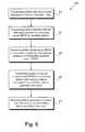
- FIG. 5there is shown exemplary flowchart 500 depicting a method for performing an initial channel estimation procedure between transmitting and receiving stations in a powerline network in accordance with one embodiment of the present invention.
- Certain details and featureshave been left out of flowchart 500 of FIG. 5 that are apparent to a person of ordinary skill in the art.
- a stepmay consist of one or more sub-steps or may involve specialized equipment, as known in the art. While steps 502 through 510 shown in flowchart 500 are sufficient to describe one embodiment of the present invention, other embodiments of the invention may utilize steps different from those shown in flowchart 500.
- a transmitting station with data to send to a receiving stationdetermines that it (i.e. the transmitting station) has no valid tone maps.
- the transmitting stationinitiates a channel estimation procedure by sending a sound MPDU (MAC Protocol Data Unit) with SRC (Sound Reason Code) set to indicate sounding for initial channel estimation.
- This MPDUwhich is also referred to as an "initial transmission” in the patent application, specifies the maximum number of tone maps that the transmitting station can allocate to this "link.”
- a connectionis decomposed into one or more unidirectional data flows called "links.”
- the sound MPDUis used during channel estimation to estimate the characteristics of the channel. Initial channel estimation can take place in either the CP or the CFP.
- the receiving stationsends a sound MPDU with SAF (Sound ACK Flag) bit in the FC (Frame Control) field appropriately set to acknowledge reception of the sound MPDU from the transmitting station.
- the transmitting stationcontinues to send sound MPDUs to the receiving station until the receiving station indicates that it has sufficient data to generate tone maps.
- the receiving stationcan send a sound MPDU to the transmitting station with the SAF and the SCF (Sound Complete Flag) appropriately set to indicate that it (i.e. the receiving station) has sufficient data to generate the tone maps.
- the receiving stationgenerates a new tone maps and sends it to the transmitting station as a default tone map.
- the new tone mapcan be sent in a CEI (Channel Estimation Indication) message having a response type field that indicates that the message includes a default tone map that is generated as a result of the initial channel estimation procedure.
- CEIChannel Estimation Indication
- the receiving stationcan also generate one or more powerline cycle adapted tone maps.
- the transmitting stationmust contend for the channel prior to sending sound MPDUs to the receiving station. Conducting the initial channel estimation procedure in the CP may preclude the transmitting station from transmitting sound MPDUs during certain parts of the powerline cycle. Similarly, if the initial channel estimation procedure is performed in the CFP, the transmitting station may lack sufficient allocation to span a complete powerline cycle. In either case, the receiving station is required to provide a tone map referred to as the default tone map that is valid for all portions of the beacon period (or powerline cycle).
- a dynamic channel adaptation procedurecan be performed by the receiving station after the initial channel estimation procedure has been performed.
- the dynamic channel adaptation procedurecan result in dynamic updates to the default tone map (i.e. replacing an existing default tone map with a new default tone map).
- This procedurecan also result in the generation of powerline cycle adapted tone maps that are valid at various intervals of the powerline cycle, where some of powerline cycle adapted tone maps may replace existing tone maps.
- powerline cycle adapted tone mapsare fine tuned for channel characteristics within a specific interval of the powerline cycle.
- Tone mapsneed to be updated and refreshed on a regular basis, otherwise they are declared as stale, and cannot be used in connections. This adaptation is needed to capture changes of the channel resulting from removal or addition of equipment in the neighborhood of the receiving or transmitting station, for example.
- the health of an active linkis constantly monitored by both the receiving and transmitting stations (the transmitting station can receive feedback from the receiving station by means of the Selective ACK mechanism).
- the stationscan request more resources from the CCo. More resources may be needed, for example, because the channel has degraded or because the traffic presented to the transmitting station by the application has increased.
- the stationscan indicate their resource needs to the CCo through special fields in the FC (Frame Control) field of each transmission.
- FCFrame Control
- Each transmission on the channelstarts with a special portion called the Frame Control (FC), which provides special information to the receiving station (e.g. what tone map is used in the modulation of the payload, or what code rate is used for error correction).
- FCFrame Control
- One of the fields in the FCprovides an indication of how many blocks are waiting for transmission in the transmitting station. If the number of blocks waiting for transmission appears excessive (i.e. if the transmitting station is suffering from congestion), the CCo, which can monitor the FC from all the transmissions in the powerline network, can allocate more resources to that connection. Additional allocations can be temporary (e.g.
- Allocation changescan also be longer term to deal with changes in the channel to which the PHY layer cannot simply adapt, or with changes in the traffic load caused by a particular application.
- FIG. 6Aillustrates an exemplary MPDU format for use by HPAV system 100 in FIG. 1 .
- long MPDU 602includes frame control block 604 and MPDU payload 606.
- Long MPDU 602refers to an MPDU that carries payload information in addition to frame control information and is used in AV-only mode.
- FIG. 6Billustrates an exemplary MPDU format for use by HPAV system 100 in FIG. 1 .
- short MPDU 650only includes a frame control block, which includes frame control information.
- the frame control blockcan comprise 128 bits.
- the present inventionprovides an HPAV system including stations that communicate via a powerline in a powerline network, where each of the stations can be configured to generate one or more tone maps for communicating with each of the other stations, and where the tone maps indicate an amount of information that can be reliably carried in different tones.
- Each of the stationscan be further configured to monitor its bandwidth needs and communicate its bandwidth needs to a CCo (central coordinator) for allocation of additional resources.
- CCocentral coordinator
Landscapes
- Engineering & Computer Science (AREA)
- Computer Networks & Wireless Communication (AREA)
- Signal Processing (AREA)
- Power Engineering (AREA)
- Mobile Radio Communication Systems (AREA)
- Small-Scale Networks (AREA)
- Cable Transmission Systems, Equalization Of Radio And Reduction Of Echo (AREA)
- Synchronisation In Digital Transmission Systems (AREA)
Description
- The present invention relates generally to communication over an Ethernet-Class network and, more specifically to communication over a powerline network.
- The vision of the networked home has driven many a business plan, but product offerings to date have been too limited in capability or in market potential to achieve the dream. Home networking is different than networking in the workplace. The applications are different, the traffic patterns are different, and the media available to carry the data are different. Certainly home networking users will want to transfer files between their computers and share peripherals such as printers. They will want gateways to broadband access so they can share their Internet connection between multiple devices. Users will also want other services, such as voice-over-IP (VoIP), streaming media for entertainment, and support for multi-player networked games.
- While some newer houses are wired with cables suitable for Ethernet, most are not. Thus, if choices for home network physical media are limited to phone wiring, wireless, and power line, there are a mixed bag of attributes.
- There has been a proliferation of wireless networking and related components in recent years. However, wireless communication suffers from limited range and less than universal coverage, i.e. certain areas of the home cannot communicate with others. These issues are particularly prominent in certain types of construction that result in poor signal propagation, such as those using steel frame and brick walls. Solutions to these issues are expensive and complex, and require some technical acumen not available to the average homeowner.
- Although telephone line networking may at first appear to be a solution, many households lack phone jacks at convenient locations to achieve the foreseeable benefits of home networking. For instance, some older houses may only have one phone jack located in the kitchen for use in the kitchen and other living areas (e.g. living room, family room, etc). Thus, it may be inconvenient or messy to provide network connections to remote devices. This picture is particularly unfavorable in less developed countries. Power plugs, on the other hand, are located in almost every room in the home, and some homes have multiple power outlets located on every wall of every room. The power line appears to be the most difficult medium of these three for communication, but it does have two appealing attributes. First, as with phone lines, no RF conversion hardware is needed and, thus, the cost can be low compared to wireless solutions. But more importantly, power outlets are almost everywhere someone might want to use a networked device at home.
- The power line medium is a harsh environment for communication. For instance, the channel between any two outlets in a home has the transfer function of an extremely complicated transmission line network with many unterminated stubs and some having terminating loads of varying impedance. Such a network has an amplitude and phase response that varies widely with frequency. At some frequencies the transmitted signal may arrive at the receiver with relatively little loss, while at other frequencies it may be driven below the noise floor. Worse, the transfer function can change with time. This might happen because the homeowner has plugged a new device into the power line, or if some of the devices plugged into the network have time-varying impedance. As a result, the transfer function of the channel between outlet pairs may vary over a wide range. In some cases, a broad swath of bandwidth may be suitable for high quality transmission, while in other cases the channel may have a limited capacity to carry data.
- Also, unplanned device usage by the homeowner can cause random variations in the transfer function of the channel between outlet pairs. As a result, the suitability of the channel's bandwidth for high quality transmission over the power line is impossible to predict before use of the channel is needed. Additionally, the bandwidth requirements of a connection between a receiver and a transmitter can change after the connection has been established, which can significantly impact Quality of Service (QoS) provided by the connection.
- Since a connection between a pair of networked devices can require varying channel capacity, issues involving availability of channel bandwidth bring about concerns regarding the overall throughput of the network, QoS for each connection, monitoring of connection requirements, and adaptability of network resources. Accordingly, there is a need in the art for management and monitoring schemes that can effectively and efficiently address such concerns.
- Background art includes US Patent Application Publications (
US 2004/208139 A1) to Iwamura , (US 2004 0136396 A1) to Yonge, III et al. , and (US 2004 0184427 A1) to Lynch et al. US 2004/208139 A1 discloses an OFDM-TDMA power line communication system, where time slot and carrier frequencies are assigned in a manner that reallocates time slots and carrier frequencies to enhance the efficiency of utilization of bandwidth. The reassignments are communicated between transmitting and receiving stations by transmitting tone maps that designate the reassignment of the time slots and carriers. Several variations are presented depending upon the circumstances of channel use and prior assignment of time slots and channels.US 2004 0136396 A1 discloses a method of operating in a network in which stations communicate over a shared medium is described. The method provides regularly repeated contention free intervals, CSMA communication during times outside the contention free intervals, and distributed control over the initiation and makeup of the contention free intervals to a plurality of stations so that any of the plurality of stations can independently initiate transmission within the contention free interval.US 2004 0184427 A1 discloses a station to serve as a proxy for responding to a multicast message is selected using dynamically maintained information about other stations communicatively coupled to a shared communications network. The dynamically maintained information is used to select a station having a high probability of replying to the multicast message. Network performance may be further improved by re-selecting proxies when a multicast frame fails to acknowledged.- The present invention is directed to method and system for bandwidth management in a powerline network. More specifically, the invention provides a method and system for estimating channel capacity and monitoring connection requirements of networked devices to achieve effective bandwidth management in a powerline network.
- In one aspect, a powerline network includes a number of stations including a central coordinator for coordinating transmissions of each of the stations. Each of the stations is configurable to generate one or more tone maps for communicating with each of the other stations in the powerline network. Each tone map includes a set of tones to be used on a communication link between two of the stations. Each tone map further includes a unique set of modulation methods for each tone. Each of the stations is further configurable to generate a default tone map for communicating with each of the other stations, where the default tone map is valid for all portions of a powerline cycle. Each of the stations is further configurable to monitor its bandwidth needs and to request additional bandwidth from the central coordinator. Each of the stations is further configurable to indicate a bandwidth need in a frame control field of a transmission, where the central coordinator is configurable to monitor the frame control field of the transmission so as to respond to the bandwidth need. Each of the tone maps can be generated as a result of a channel estimation procedure during a connection between two of the stations, where the channel estimation procedure includes measuring characteristics of a channel.
- Other features and advantages of the present invention will become more readily apparent to those of ordinary skill in the art after reviewing the following detailed description and accompanying drawings.
- The features and advantages of the present invention will become more readily apparent to those ordinarily skilled in the art after reviewing the following detailed description and accompanying drawings, wherein:
FIG. 1 illustrates an overview of a HPAV (HomePlug Audio Video) system, according to one embodiment of the present application;FIG. 2A illustrates a diagram of an exemplary powerline network configuration for the HPAV system inFIG. 1 .FIG. 2B illustrates a diagram of another exemplary powerline network configuration for the HPAV system inFIG. 1 .FIG. 2C illustrates a diagram of another exemplary powerline network configuration for the HPAV system inFIG. 1 .FIG. 3 illustrates a diagram of an exemplary HPAV transceiver forHPAV system 100 inFIG. 1 .FIG. 4 illustrates a diagram of an exemplary beacon period, according to one embodiment of the present invention.FIG. 5 illustrates a flow diagram for performing a channel estimation procedure according to one embodiment of the present invention.FIG. 6A illustrates a diagram of an exemplary MAC protocol data unit forHPAV system 100 inFIG. 1 .FIG. 6B illustrates a diagram of another exemplary MAC protocol data unit forHPAV system 100 inFIG. 1 .- Although the invention is described with respect to specific embodiments, the principles of the invention, as defined by the claims appended herein, can obviously be applied beyond the specifically described embodiments of the invention described herein. Moreover, in the description of the present invention, certain details have been left out in order to not obscure the inventive aspects of the invention. The details left out are within the knowledge of a person of ordinary skill in the art.
- The drawings in the present application and their accompanying detailed description are directed to merely example embodiments of the invention. To maintain brevity, other embodiments of the invention which use the principles of the present invention are not specifically described in the present application and are not specifically illustrated by the present drawings. It should be borne in mind that, unless noted otherwise, like or corresponding elements among the figures may be indicated by like or corresponding reference numerals.
FIG. 1 illustrates an overview of HPAV (HomePlug Audio Video)system 100, according to one embodiment of the present application. As shown,HPAV system 100 includes PHY (Physical) layer 110, MAC (Media Access Control)layer 120 andconvergence layer 130. WhenHPAV system 100 is in transmit mode, PHY layer 110 performs error-control correction, mapping into OFDM (Orthogonal Frequency Division Multiplexing) symbols, and generation of time-domain waveforms;MAC layer 120 determines the correct position of transmission, formats data frames into fixed-length entities for transmission on the channel and ensures timely and error-free delivery through Automatic Repeat Request (ARQ); andconvergence layer 130 performs bridging, classification of traffic into connections, and data delivery smoothing functions. Conversely, whenHPAV system 100 is in receive mode, PHY layer 110,MAC layer 120 andconvergence layer 130 perform the corresponding functions in the reverse.HPAV system 100 utilizes OFDM modulation technique due to its inherent adaptability in the presence of frequency selective channels, its resilience to narrow band interference, and its robustness to impulsive noise. Through the use of time-domain pulse shaping of the OFDM symbols, deep frequency notches can be achieved without the additional requirement of transmit notch filters.HPAV system 100 employs 1155 carriers, in the range from 1.80 MHz to 30.00 MHz.FIG. 2A illustrates an exemplary Audio Video Logical Network (AVLN) forHPAV system 100 inFIG. 1 . An AVLN comprises a set of stations that have the same Network Membership Key (NMK). In an AVLN, which is also generally referred to as a "powerline network" in the present application, one of the stations becomes the Central Coordinator (CCo), which is responsible for coordinating the transmissions of all of the stations in the network, in order to achieve maximum overall network throughput as well as good QoS for each connection. The CCo is also responsible for authenticating stations that wish to join the network, managing encryption keys, and coordinating sharing of resources with neighbor networks. A CCo can either be preconfigured as such or be automatically selected through a specified selection procedure; however, only one station in an AVLN can function as a Central Coordinator (CCo) at one time. It is noted that the stations in an AVLN (i.e. a powerline network) can communicate via a powerline (i.e. an AC line).- As shown in
FIG. 2A ,AVLN 202 includes stations A, B, C, and D and CCo1. The Physical Network (PhyNet) of a given station is the set of stations that can physically communicate with the station - at least at the level of Frame Control (FC) and ROBO (robust) mode. A PhyNet is relative to a given station, and it is possible for PhyNets of physically close-by stations to be distinct. In the present application, it is noted that a double arrow line, such asdouble arrow line 204 inFIG. 2A , indicates an ability for two stations, such as station A and CCo1, to communicate on the PHY level. Also shown inFIG. 2A , all stations can communicate with each other and, consequently, the PhyNet of all stations is the same set {A, B, C, D, CCo1}, as shown in Table 1. Two stations belonging to an AVLN can communicate with each other if they belong to each other's PhyNet. Further shown inFIG. 2A ,AVLN 202 coincides with the PhyNet of each station inAVLN 202.Table 1 Physical Networks (PhyNets) in ... Station Figure 2A Figure 2B Figure 2C A {A,B,C,D,CCo1} {A,B,CCo1} {A,B,CCo1} B {A,B,C,D,CCo1} {A,B,CCo1} {A,B,CCo1} C {A,B,C,D,CCo1} {C,D,CCo2} {C,D,CCo1} D {A,B,C,D,CCo1} {C,D,CCo2} {C,D} CCo1 {A,B,C,D,CCo1} {A,B,CCo1,CCo2} {A,B,C,CCo1} CCo2 N/A {C,D,CCo1,CCo2} N/A FIG. 2B illustrates two exemplary AVLNs forHPAV system 100 inFigure 1 . As shown inFIG. 2B ,AVLN 210 includes stations A and B and CCo1 andAVLN 212 includes CCo2 and stations C and D. The PhyNet for each station inFIG. 2B is shown in Table 1.FIG. 2C illustrates an exemplary AVLN forHPAV system 100 inFigure 1 . As shown inFIG. 2C ,AVLN 220 includes CCo1 and stations A, B, C, and D. The PhyNet for each station inFIG. 2C is shown in Table 1.FIG. 3 shows a diagram of an exemplary HPAV transceiver forHPAV system 100 inFIG. 1 .HPAV transceiver 300 includestransmitter side 310, which uses OFDM modulation, andreceiver side 360. Ontransmitter side 310, the PHY layer (e.g. PHY layer 110 inFigure 1 ) receives its inputs from the MAC layer (e.g. MAC layer 120). Three separate processing chains are shown inFIG. 3 for different encoding for HomePlug 1.0.1 Frame Control (FC)data 312, HomePlug AV Frame Control data 314 and HomePlugAV Payload data 316, which are processed by 1.0.1FC encoder 320,AV FC encoder 330 and AV payload data encoder 340, respectively. The outputs of the three encoders lead into a common OFDM modulation structure, includingmapper 350, Inverse Fast Fourier Transform (IFFT)processor 352, cyclic prefix insertion, symbol window and overlap block 354, andpreamble insertion 356, which eventually feeds Analog Front End (AFE)module 358 that couples the signal topower line medium 390.- At
receiver side 360,AFE 365 operates with an Automatic Gain Controller (AGC) 368 and a time-synchronization module 370 to feed separate frame control and payload data recovery circuits. The frame control data is recovered by processing the received sample stream through 384-point FFT 372 for HomePlug 1.0.1 delimiters, and 3072-point FFT 374 for HomePlug AV, and through separateframe control decoders point FFT 374,demodulator 375, and throughde-interleaver 385,turbo convolutional decoder 386, andde-scrambler 387 of AVpayload data decoder 384 to recover the AV payload data. - In the present invention, the CCo of a network (e.g. CCo1 of
AVLN 202 inFIG. 2A ) transmits a special signal called the beacon, which contains system-wide information, such as the network ID, the number of neighboring networks with which it coordinates, the current schedule of transmissions (e.g. which station is allowed to transmit and when), and the mode of the network (e.g. if it is in HPAV or in HPAV Hybrid mode). The beacon can also contain responses to messages from specific stations that request resources, request to join the network, or are delivered an encryption key, etc. The beacon can be sent by the CCo at regular intervals that are tied to a specific phase of the power cycle, as discussed below in relation toFIG. 4 . The beacon is transmitted in a so-called ROBO (Robust) mode, which is used for reliable reception of the beacon by other stations, where each station experiences a different channel characteristic from the CCo to the station. In the ROBO mode, modulation is independent of the characteristics of the channel, and robustness is achieved through low rate coding, low density modulation, and repetition and interleaving of the payload. - Each HPAV station (e.g. stations A, B, C, and D in
FIG. 2A ) monitors the channel for the presence of HP1.0 devices. When a station detects the presence of HP1.0 devices, it notifies the CCo (e.g. CC01 inFIG. 2A ), which in turn switches the network (e.g.AVLN 202 inFIG. 2A ) to the HPAV Hybrid mode. In the Hybrid mode operation, HPAV networks avoid interference from HP1.0 stations by coaxing the HP1.0 stations to transmit only in the CSMA/CA region of the beacon period. Thus HPAV stations and HP1.0 stations can coexist on the same medium, while HPAV stations maintain all the advantages of scheduled transmissions in the contention-free portion of the period. FIG. 4 illustrates an exemplary beacon period synchronized to an exemplary powerline cycle, according to one embodiment of the present invention. As shown inFIG. 4 , beacon period 402 (i.e. the time between two consecutive beacon transmissions) is substantially equal to two periods ofpowerline cycle 404. For example, for a powerline frequency of 60 Hz (i.e. for a 60 Hz system), the beacon period is nominally equal to 33.33 milliseconds (ms). For example, for a powerline frequency of 50 Hz (i.e. for a 50 Hz system),beacon Period 402 is nominally equal to 40 ms. In one embodiment,beacon period 402 can be precisely equal to two periods ofpowerline cycle 404. As further shown inFIG. 4 , the start ofbeacon period 402 can be offset from the start of a powerline cycle by a fixed duration.- As also shown in
FIG. 4 ,beacon period 402 includesbeacon region 406, CSMA (Carrier Sense Multiple Access)region 408, and reservedregion 410.Beacon region 406 includes the beacon, which is generated by a CCo and can include a Preamble, a Frame Control, and a beacon payload. The CCo ensures that the beacon remains synchronized to the powerline cycle, independent of the CCo local clock frequency. - Information describing allocations within
beacon period 402 is broadcast in the beacon payload by using one or more beacon Entries.Beacon region 406 also includes information regarding the duration ofCSMA region 408 and reservedregion 410.CSMA region 408 includes persistent sharedCSMA allocation region 416, which is allocated to connections (i.e. sessions between transmitting and receiving stations) that use CSMA channel-access mechanism.CSMA region 408 is a contention period (CP) which is also known as CSMA/CA (Carrier Sense Multiple Access/contention access) period.Reserved region 410, which is the section ofbeacon period 402 during which only one station has permission to transmit, is further divided into persistent allocation region 412 andnon-persistent allocation region 414. Persistent allocation region 412 is allocated to connections (i.e. sessions between transmitting and receiving stations), where the connections require QoS (Quality of Service). Persistent allocation region 412 is a contention free period (CFP) and can utilize TDMA (Time Division Multiple Access) channel access.Non-persistent allocation region 414 is allocated to one or more of the following: - (a) active connections that have allocation in persistent allocation region 412 but may need extra capacity, either because the channel has deteriorated for a brief or longer period of time, or because the requirements of a particular application have increased (e.g. during video or audio fast forward);
- (b) an additional CSMA period (e.g. when the CCo senses high level of collisions in the regular CSMA period; and
- (c) special system needs, such as a discover beacon, whose purpose is to discover hidden nodes (i.e. stations) that cannot detect or hear the CCo.
- In the invention's HPAV system (
e.g. HPAV system 100 inFIG. 1 ), channel estimation is a process of measuring the characteristics of a powerline channel that is utilized to adapt the operation of the PHY (e.g. PHY layer 110 inFIG. 1 ) to provide optimal performance. After a station joins a powerline network, and before it (i.e. the station) engages in extensive exchange of data with other stations, the station estimates the channel between itself and the other station(s) with which it desires to communicate. As a result of channel estimation, one or more tone maps, which are lists that indicate the amount of information that can be reliably carried in different tones (portions of the spectrum), are selected for different intervals within the beacon period (e.g. beacon period 402 inFIG. 4 ). Often more than one tone map is needed between the same pair of stations because the channel is sufficiently different in different portions of the powerline cycle. A tone map includes a set (or list) of tones to be used on a particular unicast communication link between two stations in the powerline network. The tone map further includes a unique set of modulation methods for all of the tones in the set of tones. - Channel estimation can include selection of the modulation method(s) used on each carrier (i.e. tone), selection of the FEC (Forward Error Correction) rate, selection of the guard interval length, and selection of the intervals within the AC line cycle (i.e. the powerline cycle) where a particular tone map setting applies. The FEC rate and guard interval length can vary over the powerline cycle period, but they are the same for all carriers at any given time.
- All stations in the powerline network establish a default tone map that is valid for reception by the particular station in all of the CSMA and CFP period (i.e. the whole Beacon Period a station may transmit). In addition, stations may establish AC line cycle adapted Tone Maps, i.e. Tone Maps that are valid in portion(s) of the Beacon Period and the underlying AC line cycle.
- A channel estimation procedure enables a transmitting station to obtain tone maps that can be used at various intervals of the powerline cycle while communicating with a particular receiving station. Powerline channels are unique between each transmitting station and receiving station. As a result, the channel estimation procedure must be executed independently between each transmitting station and receiving station. The channel estimation procedure also includes mechanisms for negotiating the number of tone maps that can be used, maintaining lists of valid tone maps, and maintaining the lists of intervals within the powerline cycle where each tone map may be used. The channel estimation procedure can be divided into an initial channel estimation procedure and a dynamic channel adaptation procedure. The transmitting station invokes an initial channel estimation procedure when it needs to transmit data to a particular receiving station and does not have any valid tone maps.
- Referring now to
FIG. 5 , there is shownexemplary flowchart 500 depicting a method for performing an initial channel estimation procedure between transmitting and receiving stations in a powerline network in accordance with one embodiment of the present invention. Certain details and features have been left out offlowchart 500 ofFIG. 5 that are apparent to a person of ordinary skill in the art. For example, a step may consist of one or more sub-steps or may involve specialized equipment, as known in the art. Whilesteps 502 through 510 shown inflowchart 500 are sufficient to describe one embodiment of the present invention, other embodiments of the invention may utilize steps different from those shown inflowchart 500. - Beginning at
step 502, a transmitting station with data to send to a receiving station determines that it (i.e. the transmitting station) has no valid tone maps. Atstep 504, the transmitting station initiates a channel estimation procedure by sending a sound MPDU (MAC Protocol Data Unit) with SRC (Sound Reason Code) set to indicate sounding for initial channel estimation. This MPDU, which is also referred to as an "initial transmission" in the patent application, specifies the maximum number of tone maps that the transmitting station can allocate to this "link." Within the MAC, a connection is decomposed into one or more unidirectional data flows called "links." The sound MPDU is used during channel estimation to estimate the characteristics of the channel. Initial channel estimation can take place in either the CP or the CFP. - At
step 506, the receiving station sends a sound MPDU with SAF (Sound ACK Flag) bit in the FC (Frame Control) field appropriately set to acknowledge reception of the sound MPDU from the transmitting station. Atstep 508, the transmitting station continues to send sound MPDUs to the receiving station until the receiving station indicates that it has sufficient data to generate tone maps. For example, the receiving station can send a sound MPDU to the transmitting station with the SAF and the SCF (Sound Complete Flag) appropriately set to indicate that it (i.e. the receiving station) has sufficient data to generate the tone maps. Atstep 510, the receiving station generates a new tone maps and sends it to the transmitting station as a default tone map. The new tone map can be sent in a CEI (Channel Estimation Indication) message having a response type field that indicates that the message includes a default tone map that is generated as a result of the initial channel estimation procedure. After generating the default tone map, the receiving station can also generate one or more powerline cycle adapted tone maps. - If the initial channel estimation procedure is performed in the CP, the transmitting station must contend for the channel prior to sending sound MPDUs to the receiving station. Conducting the initial channel estimation procedure in the CP may preclude the transmitting station from transmitting sound MPDUs during certain parts of the powerline cycle. Similarly, if the initial channel estimation procedure is performed in the CFP, the transmitting station may lack sufficient allocation to span a complete powerline cycle. In either case, the receiving station is required to provide a tone map referred to as the default tone map that is valid for all portions of the beacon period (or powerline cycle).
- A dynamic channel adaptation procedure can be performed by the receiving station after the initial channel estimation procedure has been performed. The dynamic channel adaptation procedure can result in dynamic updates to the default tone map (i.e. replacing an existing default tone map with a new default tone map). This procedure can also result in the generation of powerline cycle adapted tone maps that are valid at various intervals of the powerline cycle, where some of powerline cycle adapted tone maps may replace existing tone maps. In contrast to the default tone map, powerline cycle adapted tone maps are fine tuned for channel characteristics within a specific interval of the powerline cycle. Thus, a powerline cycle adapted tone map should be used by the transmitting station whenever one is available and can be used (based on the CPF field in CEI). Tone maps need to be updated and refreshed on a regular basis, otherwise they are declared as stale, and cannot be used in connections. This adaptation is needed to capture changes of the channel resulting from removal or addition of equipment in the neighborhood of the receiving or transmitting station, for example.
- During a connection, the health of an active link is constantly monitored by both the receiving and transmitting stations (the transmitting station can receive feedback from the receiving station by means of the Selective ACK mechanism). When one station senses that more resources are needed to satisfy the QoS requirements of the connection, the stations can request more resources from the CCo. More resources may be needed, for example, because the channel has degraded or because the traffic presented to the transmitting station by the application has increased.
- In addition to explicit requests for additional resources by the stations involved in the connection, the stations can indicate their resource needs to the CCo through special fields in the FC (Frame Control) field of each transmission. Each transmission on the channel starts with a special portion called the Frame Control (FC), which provides special information to the receiving station (e.g. what tone map is used in the modulation of the payload, or what code rate is used for error correction). One of the fields in the FC provides an indication of how many blocks are waiting for transmission in the transmitting station. If the number of blocks waiting for transmission appears excessive (i.e. if the transmitting station is suffering from congestion), the CCo, which can monitor the FC from all the transmissions in the powerline network, can allocate more resources to that connection. Additional allocations can be temporary (e.g. allocations communicated in Non-persistent allocations) to deal with short-term link degradation that results from changes in channel characteristics to which the PHY layer adapts successfully. Allocation changes can also be longer term to deal with changes in the channel to which the PHY layer cannot simply adapt, or with changes in the traffic load caused by a particular application.
FIG. 6A illustrates an exemplary MPDU format for use byHPAV system 100 inFIG. 1 . InFIG. 6A ,long MPDU 602 includesframe control block 604 andMPDU payload 606.Long MPDU 602 refers to an MPDU that carries payload information in addition to frame control information and is used in AV-only mode.Frame control block 604, which can comprise 128 bits, for example, includes frame control information andMPDU payload 606 includes payload information.FIG. 6B illustrates an exemplary MPDU format for use byHPAV system 100 inFIG. 1 . InFIG. 6B ,short MPDU 650 only includes a frame control block, which includes frame control information. Inshort MPDU 650, the frame control block can comprise 128 bits.- Thus, as discussed above, the present invention provides an HPAV system including stations that communicate via a powerline in a powerline network, where each of the stations can be configured to generate one or more tone maps for communicating with each of the other stations, and where the tone maps indicate an amount of information that can be reliably carried in different tones. Each of the stations can be further configured to monitor its bandwidth needs and communicate its bandwidth needs to a CCo (central coordinator) for allocation of additional resources. As a result, the present invention achieves an HPAV system that advantageously provides effective bandwidth management in a powerline network environment.
- From the above description of the invention it is manifest that various techniques can be used for implementing the concepts of the present invention without departing from its scope. Moreover, while the invention has been described with specific reference to certain embodiments, a person of ordinary skill in the art would recognize that changes could be made in form and detail without departing from the spirit and the scope of the invention. For example, it is contemplated that the circuitry disclosed herein can be implemented in software and/or hardware, and the software may be stored in any storage medium or memory. The described embodiments are to be considered in all respects as illustrative and not restrictive. It should also be understood that the invention is not limited to the particular embodiments described herein, but is capable of many rearrangements, modifications, and substitutions without departing from the scope of the invention.
Claims (18)
- A powerline network (202, 210, 212, 220) comprising:a plurality of stations (A, B, C, D) including a central coordinator (CCo1, CCo2) for coordinating transmissions of each of said plurality of stations, said central coordinator capable of generating beacons, wherein said beacons define beacon periods (402) beginning a fixed offset (Δ) from a zero crossing of a powerline cycle (404) and contain at least transmission schedules for at least said beacon periods;wherein each of said plurality of stations comprises a channel estimator to generate one or more tone maps to be used on a communication link (204) between any two of said plurality of stations, to negotiate a number of usable tone maps, to maintain lists of valid tone maps, and to maintain lists of intervals within a beacon period where each tone map may be used; andwherein each said tone map lists a set of tones to be used for a particular interval within a beacon period.
- The powerline network (202, 210, 212, 220) of claim 1, wherein said each of said plurality of stations (A, B, C, D) is further configurable to update said one or more tone maps on a regular basis to adjust to changes in said channels during intervals of said powerline cycle (404).
- The powerline network (202, 210, 212, 220) of claim 1, wherein said each of said plurality of stations (A, B, C, D) is further configurable to generate a default tone map for communicating with said each other of said plurality of stations, and wherein said default tone map is valid for all portions of a said powerline cycle (404).
- The powerline network (202, 210, 212, 220) of claim 1, wherein said each of said plurality of stations (A, B, C, D) is further configurable to monitor its bandwidth needs and to request additional bandwidth from said central coordinator (CCo1, CCo2).
- The powerline network (202, 210, 212, 220) of claim 1, wherein said each of said plurality of stations (A, B, C, D) is further configurable to indicate a bandwidth need in a frame control field of a transmission (604).
- The powerline network (202, 210, 212, 220) of claim 1, wherein each of said one or more tone maps is valid for a specific interval of said powerline cycle (404).
- The powerline network (202, 210, 212, 220) of claim 1, wherein said each of said plurality of stations is further configurable to generate a default tone map, and wherein said default tone map is further used in all of a beacon period (402).
- A method for estimating a channel between two of a plurality of stations (A, B, C, D) in communication in a powerline network (202, 210, 212, 220), said method comprising:receiving by one of said plurality of stations an initial transmission from another one of said plurality of stations;generating one or more tone maps by a channel estimator in said one of said plurality of stations to be used on a communication link (204) with said another one of said stations via a powerline, said channel estimator to negotiate a number of usable tone maps, to maintain lists of valid tone maps, and to maintain lists of intervals within a beacon period (402) where each tone map may be used, said beacon period beginning at a fixed offset (Δ) from a zero crossing of a powerline cycle (404) and defined by a beacon containing at least a transmission schedule for at least said beacon period; andwherein each said tone map lists a set of tones to be used for a particular interval within a beacon period.
- The method of claim 8, further comprising updating said one or more tone maps by said one of said plurality of stations (A, B, C, D) to adjust to a change in a channel during intervals of said powerline cycle (404).
- The method of claim 8, wherein said one or more tone maps comprises a default tone map, and wherein said default tone map is valid for all portions of said powerline cycle (404).
- The method of claim 8, further comprising:monitoring a bandwidth need by said one of said plurality of stations (A, B, C, D) wherein said plurality of stations includes a central coordinator (CCo1, CCo2) for coordinating transmissions of each of said plurality of stations; andrequesting additional bandwidth from said central coordinator by said one of said plurality of stations.
- The method of claim 8, further comprising:indicating a bandwidth need in a frame control field (604) of a transmission by said one of said plurality of stations (A, B, C, D).
- The method of claim 10, wherein said two of said plurality of stations (A, B, C, D) comprise a receiving station (360) and a transmitting station (310), and wherein said default tone map is generated by a method comprising:receiving by said receiving station sound data units transmitted by said transmitting station; andutilizing said sound data units by said receiving station to generate said default tone map.
- The method of claim 13, further comprising sending by said receiving station (360) said default tone map to said transmitting station (310) in a channel estimation indication message.
- The receiving device (360) of claim 17, wherein said receiving device is further configurable to communicate a bandwidth need to said central coordinator (CCo1, CCo2) in a frame control field of a transmission (604).
- The receiving device (360) of claim 17, wherein said receiving device is further configurable to generate a default tone map for communicating with said transmitting device (310), and wherein said default tone map is valid for all portions of said powerline cycle (404).
- A receiving device (360) of a powerline network (202, 210, 212, 220), the receiving device comprising:a receiver configurable to receive an initial transmission from one of a plurality of stations (A, B, C, D) of said powerline network; anda channel estimator configurable to generate one or more tone maps to be used on a communication link (204) with said one of said stations, said channel estimator to negotiate a number of usable tone maps, to maintain lists of valid tone maps, and to maintain lists of intervals within a beacon period (402) where each tone map may be used, said beacon period beginning at a fixed offset (Δ) from a zero crossing of a powerline cycle (404) and defined by a beacon containing at least a transmission schedule for at least said beacon period; andwherein each said tone map lists a set of tones to be used for a particular interval within a beacon period.
- A method for a plurality of stations (A, B, C, D) in communication in a powerline network (202, 210, 212, 220), said method comprising:generating beacons by a central coordinator (CCo1, CCo2) for coordinating transmissions of each of said plurality of stations, wherein said beacons define beacon periods (402) beginning at a fixed offset (Δ) from a zero crossing of a powerline cycle (404) and contain at least transmission schedules for at least said beacon period;transmitting one or more sounding signals;generating, by a channel estimator, a default tone map which is valid for all intervals within a beacon period;estimating characteristics of a channel between any two of said plurality of stations during intervals within said beacon period using said sounding signal; andusing said characteristics for generating one or more tone maps each for a specific interval within said beacon period;wherein said channel estimator negotiates a number of usable tone maps, maintains lists of valid tone maps, and maintains lists of intervals within a beacon period where each tone map may be used.
Applications Claiming Priority (2)
| Application Number | Priority Date | Filing Date | Title |
|---|---|---|---|
| US70271705P | 2005-07-27 | 2005-07-27 | |
| PCT/US2006/028675WO2007016034A2 (en) | 2005-07-27 | 2006-07-24 | Bandwidth management in a powerline network |
Publications (3)
| Publication Number | Publication Date |
|---|---|
| EP1908189A2 EP1908189A2 (en) | 2008-04-09 |
| EP1908189A4 EP1908189A4 (en) | 2009-10-28 |
| EP1908189B1true EP1908189B1 (en) | 2016-11-09 |
Family
ID=37709095
Family Applications (3)
| Application Number | Title | Priority Date | Filing Date |
|---|---|---|---|
| EP06788309.0AActiveEP1908189B1 (en) | 2005-07-27 | 2006-07-24 | Bandwidth management in a powerline network |
| EP06788300.9AActiveEP1908222B1 (en) | 2005-07-27 | 2006-07-24 | Flexible scheduling of resources in a noisy environment |
| EP06788301.7AActiveEP1908223B1 (en) | 2005-07-27 | 2006-07-24 | Communicating schedule and network information in a powerline network |
Family Applications After (2)
| Application Number | Title | Priority Date | Filing Date |
|---|---|---|---|
| EP06788300.9AActiveEP1908222B1 (en) | 2005-07-27 | 2006-07-24 | Flexible scheduling of resources in a noisy environment |
| EP06788301.7AActiveEP1908223B1 (en) | 2005-07-27 | 2006-07-24 | Communicating schedule and network information in a powerline network |
Country Status (5)
| Country | Link |
|---|---|
| EP (3) | EP1908189B1 (en) |
| JP (3) | JP2009504015A (en) |
| KR (3) | KR20080038366A (en) |
| CN (7) | CN101326768B (en) |
| WO (3) | WO2007016032A2 (en) |
Cited By (1)
| Publication number | Priority date | Publication date | Assignee | Title |
|---|---|---|---|---|
| US11575493B2 (en) | 2020-04-30 | 2023-02-07 | Huawei Technologies Co., Ltd. | Time synchronization method and apparatus, and storage medium |
Families Citing this family (30)
| Publication number | Priority date | Publication date | Assignee | Title |
|---|---|---|---|---|
| GB2452697A (en) | 2007-08-14 | 2009-03-18 | Nec Corp | Dynamically allocating new resources to a node provided with persistently allocated resources |
| CN101999241B (en)* | 2007-12-29 | 2013-06-12 | 上海贝尔股份有限公司 | Semi-persistent scheduling method and apparatus based on statistically multiplexing in time and frequency resources |
| EP2320285A1 (en)* | 2009-11-06 | 2011-05-11 | VEGA Grieshaber KG | Data processing device for a field device |
| EP2323443A1 (en)* | 2009-11-16 | 2011-05-18 | NEC Corporation | Method for transmitting beacon services in an area covered by several radio access technologies |
| US8938237B2 (en) | 2010-03-24 | 2015-01-20 | Nec Corporation | Stamping mechanism for beacon message transmission |
| JP5815553B2 (en)* | 2010-03-24 | 2015-11-17 | レノボ・イノベーションズ・リミテッド(香港) | Stamping mechanism for transmitting beacon messages |
| CN102939737B (en) | 2010-04-12 | 2015-10-21 | 高通股份有限公司 | For carrying out the forwarding of low overhead communication in a network |
| US8743908B2 (en)* | 2010-04-20 | 2014-06-03 | Texas Instruments Incorporated | Coexistence of prime, S-FSK and G3 devices in powerline communications |
| CN102244558B (en)* | 2010-05-12 | 2014-09-03 | 华为技术有限公司 | Data transmission method and device |
| CN102215049B (en)* | 2011-05-27 | 2014-01-29 | 杭州箭源电子有限公司 | Data sending method and data sending device |
| US9744442B2 (en) | 2012-08-27 | 2017-08-29 | Lenovo Enterprise Solutions (Singapore) Pte. Ltd. | Dynamic quality of service management in multiplayer gaming |
| AT513542B1 (en) | 2012-11-15 | 2014-07-15 | Fronius Int Gmbh | Method and arrangement for data communication between an inverter and a grid monitoring unit |
| KR101420227B1 (en)* | 2012-11-21 | 2014-07-17 | 한국전기연구원 | Fast Power Line Communication Method using Efficient Resource Allocation Scheme for Coexistence of Heterogeneous Systems |
| US9071390B2 (en)* | 2013-01-10 | 2015-06-30 | Qualcomm Incorporated | Adjusting physical layer transmission properties |
| US9237014B2 (en)* | 2013-05-28 | 2016-01-12 | Hong Kong Applied Science & Technology Research Institute Company, Limited | Partial CipherText updates using variable-length segments delineated by pattern matching and encrypted by fixed-length blocks |
| US9537641B2 (en)* | 2013-05-30 | 2017-01-03 | Qualcomm Incorporated | Channel adaptation to compensate for interference from neighbor powerline communication networks |
| US9549027B2 (en) | 2013-09-27 | 2017-01-17 | Dolby Laboratories Licensing Corporation | Network-synchronized media playback |
| US9723610B2 (en)* | 2015-04-07 | 2017-08-01 | Qualcomm Incorporated | Multi-layer timing synchronization framework |
| CN107395318B (en)* | 2016-05-17 | 2020-08-14 | 联发科技股份有限公司 | Device and method for selecting a frequency map |
| WO2018090339A1 (en)* | 2016-11-18 | 2018-05-24 | 海能达通信股份有限公司 | Wireless communication method and device, and communication apparatus |
| CN107505839B (en)* | 2017-07-21 | 2019-06-28 | 中国地质大学(武汉) | A kind of synchronous waveform method and system of virtual instrument |
| CN110768776A (en) | 2018-07-25 | 2020-02-07 | 杭州万高科技股份有限公司 | Smart power grid timing synchronization method, system, equipment and computer medium |
| CN109039381B (en)* | 2018-08-29 | 2022-08-05 | 珠海泰易科技有限公司 | Encryption method for low-voltage power line broadband carrier communication aiming at DL/T645 communication protocol |
| US11398925B2 (en)* | 2019-05-03 | 2022-07-26 | Microchip Technology Incorporated | Media access for time-sensitive and best efforts data packets, and related systems, methods and devices |
| CN111245477B (en)* | 2020-01-16 | 2022-02-22 | 磐基技术有限公司 | Power failure detection method of communication equipment |
| CN111542015B (en)* | 2020-05-11 | 2022-03-15 | 国网陕西省电力公司电力科学研究院 | MAC protocol method applied to transformer substation wireless sensor network and implementation system thereof |
| CN113794530B (en)* | 2021-09-09 | 2023-12-01 | 深圳市力合微电子股份有限公司 | TDMA-based low-power consumption micropower wireless communication method |
| CN114124600B (en)* | 2021-11-15 | 2023-06-06 | 国网湖北省电力有限公司营销服务中心(计量中心) | A power line broadband carrier system supporting home subnet and its application method |
| US12289132B2 (en)* | 2022-05-19 | 2025-04-29 | Nec Corporation | Time synchronization method with trusted beacons and distributed fiber sensing |
| EP4443752A1 (en)* | 2023-03-15 | 2024-10-09 | Hangzhou Lianxintong Semiconductor Co., Ltd. | Wired communication system for replacing in-vehicle can/lin bus |
Family Cites Families (41)
| Publication number | Priority date | Publication date | Assignee | Title |
|---|---|---|---|---|
| JPS63191423A (en)* | 1987-02-03 | 1988-08-08 | Fujitsu Ltd | Satellite communication method |
| US5553094A (en)* | 1990-02-15 | 1996-09-03 | Iris Systems, Inc. | Radio communication network for remote data generating stations |
| US6334219B1 (en)* | 1994-09-26 | 2001-12-25 | Adc Telecommunications Inc. | Channel selection for a hybrid fiber coax network |
| JPH08265241A (en)* | 1995-03-28 | 1996-10-11 | Hitachi Ltd | Satellite communication system and satellite communication method |
| US5659720A (en)* | 1995-04-27 | 1997-08-19 | Emulex Corporatioln | Computer control device for managing a timer array |
| WO1998009845A1 (en)* | 1996-09-07 | 1998-03-12 | Bayerische Motoren Werke Aktiengesellschaft | Data bus for several apparatuses |
| US6708274B2 (en)* | 1998-04-30 | 2004-03-16 | Intel Corporation | Cryptographically protected paging subsystem |
| US6567416B1 (en)* | 1997-10-14 | 2003-05-20 | Lucent Technologies Inc. | Method for access control in a multiple access system for communications networks |
| US6055316A (en)* | 1997-12-26 | 2000-04-25 | Sun Microsystems, Inc. | System and method for deriving an appropriate initialization vector for secure communications |
| JPH11261545A (en)* | 1998-03-10 | 1999-09-24 | Hitachi Denshi Ltd | Video / audio signal transmission system |
| CN1296682A (en)* | 1998-12-17 | 2001-05-23 | 三菱电机株式会社 | Transmitting method and device |
| AU3221600A (en)* | 1999-02-04 | 2000-08-25 | Electric Power Research Institute, Inc. | Apparatus and method for implementing digital communications on a power line |
| FI115494B (en)* | 1999-09-08 | 2005-05-13 | Nokia Corp | Base station frequency synchronization |
| US7388853B2 (en)* | 2000-04-07 | 2008-06-17 | Broadcom Corporation | Method for providing dynamic adjustment of frame encoding parameters in a frame-based communications network |
| US7352770B1 (en)* | 2000-08-04 | 2008-04-01 | Intellon Corporation | Media access control protocol with priority and contention-free intervals |
| JP4373598B2 (en)* | 2000-10-26 | 2009-11-25 | 株式会社日立製作所 | Power line carrier system |
| US6577231B2 (en)* | 2001-04-03 | 2003-06-10 | Thomson Licensing Sa | Clock synchronization over a powerline modem network for multiple devices |
| US6834091B2 (en)* | 2001-04-03 | 2004-12-21 | Thomson Licensing S.A. | Time synchronization for data over a powerline modem network |
| ES2186531B1 (en)* | 2001-04-19 | 2005-03-16 | Diseño De Sistemas En Silicio, S.A. | PROCEDURE FOR MULTIPLE AND MULTIPLE DATA TRANSMISSION FOR A MULTI-USER DIGITAL DATA TRANSMISSION SYSTEM POINT TO MULTIPOINT ON ELECTRICAL NETWORK. |
| WO2002093950A2 (en)* | 2001-05-14 | 2002-11-21 | Marconi Communications Gmbh | Method of, and system for, reserving timeslots in a tdma system |
| US7570656B2 (en)* | 2001-06-18 | 2009-08-04 | Yitran Communications Ltd. | Channel access method for powerline carrier based media access control protocol |
| WO2003009083A2 (en)* | 2001-07-17 | 2003-01-30 | Main.Net Communications Ltd. | Dual purpose power line modem |
| CN1656743A (en)* | 2002-05-31 | 2005-08-17 | 皇家飞利浦电子股份有限公司 | Information Routing in Wireless Networks |
| US6744766B2 (en)* | 2002-06-05 | 2004-06-01 | Meshnetworks, Inc. | Hybrid ARQ for a wireless Ad-Hoc network and a method for using the same |
| US7200178B2 (en)* | 2002-06-12 | 2007-04-03 | Texas Instruments Incorporated | Methods for optimizing time variant communication channels |
| US7307357B2 (en)* | 2002-09-30 | 2007-12-11 | Amperion, Inc. | Method and system to increase the throughput of a communications system that uses an electrical power distribution system as a communications pathway |
| WO2004038980A2 (en)* | 2002-10-21 | 2004-05-06 | Intellon Corporation | Contention-free access intervals on a csma network |
| US7277548B2 (en)* | 2002-10-23 | 2007-10-02 | Ndosa Technologies, Inc. | Cryptographic method and computer program product for use in wireless local area networks |
| US7719991B2 (en)* | 2003-01-21 | 2010-05-18 | Qualcomm Incorporated | Reverse rate indicator detection |
| US8064474B2 (en)* | 2003-03-20 | 2011-11-22 | Qualcomm Atheros, Inc. | Method and apparatus for selecting a responder to enable reliable multicast |
| US6911276B2 (en)* | 2003-04-15 | 2005-06-28 | Entegris, Inc. | Fuel cell with ultraphobic surfaces |
| US7423992B2 (en)* | 2003-04-16 | 2008-09-09 | Sony Corporation | Time slot and carrier frequency allocation in a network |
| KR101025085B1 (en)* | 2003-08-06 | 2011-03-25 | 파나소닉 주식회사 | Master station and access control method of communication system |
| JP4488828B2 (en)* | 2003-08-06 | 2010-06-23 | パナソニック株式会社 | Master station of communication system and access control method |
| JP4011527B2 (en)* | 2003-08-29 | 2007-11-21 | シャープ株式会社 | COMMUNICATION RELAY DEVICE, COMMUNICATION DEVICE, COMMUNICATION SYSTEM, COMMUNICATION METHOD, COMMUNICATION PROGRAM, AND RECORDING MEDIUM CONTAINING THE SAME |
| US7092693B2 (en)* | 2003-08-29 | 2006-08-15 | Sony Corporation | Ultra-wide band wireless / power-line communication system for delivering audio/video content |
| JP2007521766A (en)* | 2003-11-07 | 2007-08-02 | シャープ株式会社 | Network coordination system and method using limited explicit message exchange |
| JP3673268B1 (en)* | 2004-02-05 | 2005-07-20 | シャープ株式会社 | Jitter correction device |
| EP1608104B1 (en)* | 2004-06-15 | 2008-08-13 | Dublin Institute of Technology | A wireless probe for wireless local area networks |
| US8126065B2 (en)* | 2005-03-23 | 2012-02-28 | Sony Corporation | Automatic power adjustment in powerline home network |
| US20060227729A1 (en)* | 2005-04-12 | 2006-10-12 | Honeywell International Inc. | Wireless communication system with collision avoidance protocol |
- 2006
- 2006-07-24EPEP06788309.0Apatent/EP1908189B1/enactiveActive
- 2006-07-24JPJP2008524027Apatent/JP2009504015A/enactivePending
- 2006-07-24CNCN200680035606.2Apatent/CN101326768B/enactiveActive
- 2006-07-24KRKR1020087004685Apatent/KR20080038366A/ennot_activeCeased
- 2006-07-24KRKR1020087004686Apatent/KR101247294B1/enactiveActive
- 2006-07-24JPJP2008524028Apatent/JP5106394B2/enactiveActive
- 2006-07-24JPJP2008524029Apatent/JP2009504017A/enactivePending
- 2006-07-24EPEP06788300.9Apatent/EP1908222B1/enactiveActive
- 2006-07-24WOPCT/US2006/028663patent/WO2007016032A2/enactiveSearch and Examination
- 2006-07-24CNCNA2006800355657Apatent/CN101273550A/enactivePending
- 2006-07-24CNCN2006800355553Apatent/CN101273580B/enactiveActive
- 2006-07-24WOPCT/US2006/028662patent/WO2007016031A2/enactiveApplication Filing
- 2006-07-24WOPCT/US2006/028675patent/WO2007016034A2/enactiveApplication Filing
- 2006-07-24CNCN201310278303.5Apatent/CN103532809B/enactiveActive
- 2006-07-24EPEP06788301.7Apatent/EP1908223B1/enactiveActive
- 2006-07-27CNCN2006800352803Apatent/CN101317391B/enactiveActive
- 2006-07-27CNCN2006800352678Apatent/CN101542961B/ennot_activeExpired - Fee Related
- 2006-07-27CNCN2006101075871Apatent/CN101026411B/enactiveActive
- 2008
- 2008-02-27KRKR1020087004684Apatent/KR101269036B1/enactiveActive
Non-Patent Citations (1)
| Title |
|---|
| None* |
Cited By (1)
| Publication number | Priority date | Publication date | Assignee | Title |
|---|---|---|---|---|
| US11575493B2 (en) | 2020-04-30 | 2023-02-07 | Huawei Technologies Co., Ltd. | Time synchronization method and apparatus, and storage medium |
Also Published As
Similar Documents
| Publication | Publication Date | Title |
|---|---|---|
| EP1908189B1 (en) | Bandwidth management in a powerline network | |
| US8737420B2 (en) | Bandwidth management in a powerline network | |
| US8553706B2 (en) | Flexible scheduling of resources in a noisy environment | |
| US20070025266A1 (en) | Communicating schedule and network information in a powerline network | |
| US8520683B2 (en) | Managing communications over a shared medium | |
| US9413688B2 (en) | Managing distributed access to a shared medium | |
| JP2013013126A (en) | Communication method and power line communication system | |
| WO2010005733A1 (en) | Managing coexistence among signaling protocols on a shared medium | |
| US8422380B2 (en) | Dynamically reconfigurable wired network | |
| US20130070790A1 (en) | Superframe format for mv-lv communication in multi tone-mask plc networks | |
| Gavette | Homeplug av technology overview |
Legal Events
| Date | Code | Title | Description |
|---|---|---|---|
| PUAI | Public reference made under article 153(3) epc to a published international application that has entered the european phase | Free format text:ORIGINAL CODE: 0009012 | |
| 17P | Request for examination filed | Effective date:20080214 | |
| AK | Designated contracting states | Kind code of ref document:A2 Designated state(s):AT BE BG CH CY CZ DE DK EE ES FI FR GB GR HU IE IS IT LI LT LU LV MC NL PL PT RO SE SI SK TR | |
| AX | Request for extension of the european patent | Extension state:AL BA HR MK RS | |
| RAP1 | Party data changed (applicant data changed or rights of an application transferred) | Owner name:COPPERGATE COMMUNICATIONS LTD. | |
| RAP1 | Party data changed (applicant data changed or rights of an application transferred) | Owner name:COPPERGATE COMMUNICATIONS LTD. | |
| A4 | Supplementary search report drawn up and despatched | Effective date:20090929 | |
| RIC1 | Information provided on ipc code assigned before grant | Ipc:H04B 3/54 20060101ALI20090923BHEP Ipc:H04B 7/212 20060101AFI20080116BHEP | |
| DAX | Request for extension of the european patent (deleted) | ||
| RAP1 | Party data changed (applicant data changed or rights of an application transferred) | Owner name:SIGMA DESIGNS ISRAEL S.D.I LTD. | |
| 17Q | First examination report despatched | Effective date:20140526 | |
| GRAP | Despatch of communication of intention to grant a patent | Free format text:ORIGINAL CODE: EPIDOSNIGR1 | |
| INTG | Intention to grant announced | Effective date:20160404 | |
| GRAS | Grant fee paid | Free format text:ORIGINAL CODE: EPIDOSNIGR3 | |
| GRAJ | Information related to disapproval of communication of intention to grant by the applicant or resumption of examination proceedings by the epo deleted | Free format text:ORIGINAL CODE: EPIDOSDIGR1 | |
| GRAL | Information related to payment of fee for publishing/printing deleted | Free format text:ORIGINAL CODE: EPIDOSDIGR3 | |
| INTC | Intention to grant announced (deleted) | ||
| GRAR | Information related to intention to grant a patent recorded | Free format text:ORIGINAL CODE: EPIDOSNIGR71 | |
| GRAA | (expected) grant | Free format text:ORIGINAL CODE: 0009210 | |
| AK | Designated contracting states | Kind code of ref document:B1 Designated state(s):AT BE BG CH CY CZ DE DK EE ES FI FR GB GR HU IE IS IT LI LT LU LV MC NL PL PT RO SE SI SK TR | |
| INTG | Intention to grant announced | Effective date:20160930 | |
| REG | Reference to a national code | Ref country code:GB Ref legal event code:FG4D | |
| REG | Reference to a national code | Ref country code:AT Ref legal event code:REF Ref document number:844773 Country of ref document:AT Kind code of ref document:T Effective date:20161115 Ref country code:CH Ref legal event code:EP | |
| REG | Reference to a national code | Ref country code:IE Ref legal event code:FG4D | |
| REG | Reference to a national code | Ref country code:DE Ref legal event code:R096 Ref document number:602006050860 Country of ref document:DE | |
| PG25 | Lapsed in a contracting state [announced via postgrant information from national office to epo] | Ref country code:LV Free format text:LAPSE BECAUSE OF FAILURE TO SUBMIT A TRANSLATION OF THE DESCRIPTION OR TO PAY THE FEE WITHIN THE PRESCRIBED TIME-LIMIT Effective date:20161109 | |
| REG | Reference to a national code | Ref country code:LT Ref legal event code:MG4D | |
| REG | Reference to a national code | Ref country code:NL Ref legal event code:MP Effective date:20161109 | |
| REG | Reference to a national code | Ref country code:AT Ref legal event code:MK05 Ref document number:844773 Country of ref document:AT Kind code of ref document:T Effective date:20161109 | |
| PG25 | Lapsed in a contracting state [announced via postgrant information from national office to epo] | Ref country code:GR Free format text:LAPSE BECAUSE OF FAILURE TO SUBMIT A TRANSLATION OF THE DESCRIPTION OR TO PAY THE FEE WITHIN THE PRESCRIBED TIME-LIMIT Effective date:20170210 Ref country code:LT Free format text:LAPSE BECAUSE OF FAILURE TO SUBMIT A TRANSLATION OF THE DESCRIPTION OR TO PAY THE FEE WITHIN THE PRESCRIBED TIME-LIMIT Effective date:20161109 Ref country code:NL Free format text:LAPSE BECAUSE OF FAILURE TO SUBMIT A TRANSLATION OF THE DESCRIPTION OR TO PAY THE FEE WITHIN THE PRESCRIBED TIME-LIMIT Effective date:20161109 Ref country code:SE Free format text:LAPSE BECAUSE OF FAILURE TO SUBMIT A TRANSLATION OF THE DESCRIPTION OR TO PAY THE FEE WITHIN THE PRESCRIBED TIME-LIMIT Effective date:20161109 | |
| PG25 | Lapsed in a contracting state [announced via postgrant information from national office to epo] | Ref country code:PL Free format text:LAPSE BECAUSE OF FAILURE TO SUBMIT A TRANSLATION OF THE DESCRIPTION OR TO PAY THE FEE WITHIN THE PRESCRIBED TIME-LIMIT Effective date:20161109 Ref country code:ES Free format text:LAPSE BECAUSE OF FAILURE TO SUBMIT A TRANSLATION OF THE DESCRIPTION OR TO PAY THE FEE WITHIN THE PRESCRIBED TIME-LIMIT Effective date:20161109 Ref country code:FI Free format text:LAPSE BECAUSE OF FAILURE TO SUBMIT A TRANSLATION OF THE DESCRIPTION OR TO PAY THE FEE WITHIN THE PRESCRIBED TIME-LIMIT Effective date:20161109 Ref country code:IS Free format text:LAPSE BECAUSE OF FAILURE TO SUBMIT A TRANSLATION OF THE DESCRIPTION OR TO PAY THE FEE WITHIN THE PRESCRIBED TIME-LIMIT Effective date:20170309 Ref country code:AT Free format text:LAPSE BECAUSE OF FAILURE TO SUBMIT A TRANSLATION OF THE DESCRIPTION OR TO PAY THE FEE WITHIN THE PRESCRIBED TIME-LIMIT Effective date:20161109 Ref country code:PT Free format text:LAPSE BECAUSE OF FAILURE TO SUBMIT A TRANSLATION OF THE DESCRIPTION OR TO PAY THE FEE WITHIN THE PRESCRIBED TIME-LIMIT Effective date:20170309 | |
| PG25 | Lapsed in a contracting state [announced via postgrant information from national office to epo] | Ref country code:RO Free format text:LAPSE BECAUSE OF FAILURE TO SUBMIT A TRANSLATION OF THE DESCRIPTION OR TO PAY THE FEE WITHIN THE PRESCRIBED TIME-LIMIT Effective date:20161109 Ref country code:CZ Free format text:LAPSE BECAUSE OF FAILURE TO SUBMIT A TRANSLATION OF THE DESCRIPTION OR TO PAY THE FEE WITHIN THE PRESCRIBED TIME-LIMIT Effective date:20161109 Ref country code:DK Free format text:LAPSE BECAUSE OF FAILURE TO SUBMIT A TRANSLATION OF THE DESCRIPTION OR TO PAY THE FEE WITHIN THE PRESCRIBED TIME-LIMIT Effective date:20161109 Ref country code:EE Free format text:LAPSE BECAUSE OF FAILURE TO SUBMIT A TRANSLATION OF THE DESCRIPTION OR TO PAY THE FEE WITHIN THE PRESCRIBED TIME-LIMIT Effective date:20161109 Ref country code:SK Free format text:LAPSE BECAUSE OF FAILURE TO SUBMIT A TRANSLATION OF THE DESCRIPTION OR TO PAY THE FEE WITHIN THE PRESCRIBED TIME-LIMIT Effective date:20161109 | |
| REG | Reference to a national code | Ref country code:DE Ref legal event code:R097 Ref document number:602006050860 Country of ref document:DE | |
| PG25 | Lapsed in a contracting state [announced via postgrant information from national office to epo] | Ref country code:BE Free format text:LAPSE BECAUSE OF FAILURE TO SUBMIT A TRANSLATION OF THE DESCRIPTION OR TO PAY THE FEE WITHIN THE PRESCRIBED TIME-LIMIT Effective date:20161109 Ref country code:BG Free format text:LAPSE BECAUSE OF FAILURE TO SUBMIT A TRANSLATION OF THE DESCRIPTION OR TO PAY THE FEE WITHIN THE PRESCRIBED TIME-LIMIT Effective date:20170209 Ref country code:IT Free format text:LAPSE BECAUSE OF FAILURE TO SUBMIT A TRANSLATION OF THE DESCRIPTION OR TO PAY THE FEE WITHIN THE PRESCRIBED TIME-LIMIT Effective date:20161109 | |
| PLBE | No opposition filed within time limit | Free format text:ORIGINAL CODE: 0009261 | |
| STAA | Information on the status of an ep patent application or granted ep patent | Free format text:STATUS: NO OPPOSITION FILED WITHIN TIME LIMIT | |
| 26N | No opposition filed | Effective date:20170810 | |
| PG25 | Lapsed in a contracting state [announced via postgrant information from national office to epo] | Ref country code:SI Free format text:LAPSE BECAUSE OF FAILURE TO SUBMIT A TRANSLATION OF THE DESCRIPTION OR TO PAY THE FEE WITHIN THE PRESCRIBED TIME-LIMIT Effective date:20161109 | |
| REG | Reference to a national code | Ref country code:CH Ref legal event code:PL | |
| REG | Reference to a national code | Ref country code:IE Ref legal event code:MM4A | |
| REG | Reference to a national code | Ref country code:FR Ref legal event code:ST Effective date:20180330 | |
| PG25 | Lapsed in a contracting state [announced via postgrant information from national office to epo] | Ref country code:CH Free format text:LAPSE BECAUSE OF NON-PAYMENT OF DUE FEES Effective date:20170731 Ref country code:IE Free format text:LAPSE BECAUSE OF NON-PAYMENT OF DUE FEES Effective date:20170724 Ref country code:LI Free format text:LAPSE BECAUSE OF NON-PAYMENT OF DUE FEES Effective date:20170731 | |
| PG25 | Lapsed in a contracting state [announced via postgrant information from national office to epo] | Ref country code:FR Free format text:LAPSE BECAUSE OF NON-PAYMENT OF DUE FEES Effective date:20170731 | |
| PG25 | Lapsed in a contracting state [announced via postgrant information from national office to epo] | Ref country code:LU Free format text:LAPSE BECAUSE OF NON-PAYMENT OF DUE FEES Effective date:20170724 | |
| PG25 | Lapsed in a contracting state [announced via postgrant information from national office to epo] | Ref country code:MC Free format text:LAPSE BECAUSE OF FAILURE TO SUBMIT A TRANSLATION OF THE DESCRIPTION OR TO PAY THE FEE WITHIN THE PRESCRIBED TIME-LIMIT Effective date:20161109 Ref country code:HU Free format text:LAPSE BECAUSE OF FAILURE TO SUBMIT A TRANSLATION OF THE DESCRIPTION OR TO PAY THE FEE WITHIN THE PRESCRIBED TIME-LIMIT; INVALID AB INITIO Effective date:20060724 | |
| PG25 | Lapsed in a contracting state [announced via postgrant information from national office to epo] | Ref country code:CY Free format text:LAPSE BECAUSE OF NON-PAYMENT OF DUE FEES Effective date:20161109 | |
| PG25 | Lapsed in a contracting state [announced via postgrant information from national office to epo] | Ref country code:TR Free format text:LAPSE BECAUSE OF FAILURE TO SUBMIT A TRANSLATION OF THE DESCRIPTION OR TO PAY THE FEE WITHIN THE PRESCRIBED TIME-LIMIT Effective date:20161109 | |
| PGFP | Annual fee paid to national office [announced via postgrant information from national office to epo] | Ref country code:DE Payment date:20240604 Year of fee payment:19 | |
| PGFP | Annual fee paid to national office [announced via postgrant information from national office to epo] | Ref country code:GB Payment date:20250605 Year of fee payment:20 |