EP1907214B1 - Printing device fluid reservoir - Google Patents
Printing device fluid reservoirDownload PDFInfo
- Publication number
- EP1907214B1 EP1907214B1EP06773565AEP06773565AEP1907214B1EP 1907214 B1EP1907214 B1EP 1907214B1EP 06773565 AEP06773565 AEP 06773565AEP 06773565 AEP06773565 AEP 06773565AEP 1907214 B1EP1907214 B1EP 1907214B1
- Authority
- EP
- European Patent Office
- Prior art keywords
- chamber
- bubble
- fluid reservoir
- fluid
- region
- Prior art date
- Legal status (The legal status is an assumption and is not a legal conclusion. Google has not performed a legal analysis and makes no representation as to the accuracy of the status listed.)
- Not-in-force
Links
- 239000012530fluidSubstances0.000titleclaimsabstractdescription115
- 238000007639printingMethods0.000titleclaimsabstractdescription12
- 238000000034methodMethods0.000claimsdescription10
- 239000000463materialSubstances0.000claimsdescription8
- 230000008878couplingEffects0.000claimsdescription2
- 238000010168coupling processMethods0.000claimsdescription2
- 238000005859coupling reactionMethods0.000claimsdescription2
- 230000006835compressionEffects0.000claims1
- 238000007906compressionMethods0.000claims1
- 238000010586diagramMethods0.000description40
- 239000003570airSubstances0.000description26
- 239000000976inkSubstances0.000description11
- 230000007246mechanismEffects0.000description8
- 210000002683footAnatomy0.000description5
- 210000003371toeAnatomy0.000description4
- 230000015572biosynthetic processEffects0.000description3
- 230000002452interceptive effectEffects0.000description3
- 238000004519manufacturing processMethods0.000description3
- 230000008569processEffects0.000description3
- 230000009471actionEffects0.000description2
- 230000000903blocking effectEffects0.000description2
- 238000013461designMethods0.000description2
- 239000006260foamSubstances0.000description2
- 238000003780insertionMethods0.000description2
- 230000037431insertionEffects0.000description2
- 239000007769metal materialSubstances0.000description2
- 239000010935stainless steelSubstances0.000description2
- 229910001220stainless steelInorganic materials0.000description2
- 229910045601alloyInorganic materials0.000description1
- 239000000956alloySubstances0.000description1
- 239000012080ambient airSubstances0.000description1
- 230000008859changeEffects0.000description1
- 238000011161developmentMethods0.000description1
- 238000009434installationMethods0.000description1
- 238000003754machiningMethods0.000description1
- 238000012423maintenanceMethods0.000description1
- 239000011148porous materialSubstances0.000description1
- 238000007789sealingMethods0.000description1
- 238000007493shaping processMethods0.000description1
- 238000003860storageMethods0.000description1
- 238000009736wettingMethods0.000description1
Images


Classifications
- B—PERFORMING OPERATIONS; TRANSPORTING
- B41—PRINTING; LINING MACHINES; TYPEWRITERS; STAMPS
- B41J—TYPEWRITERS; SELECTIVE PRINTING MECHANISMS, i.e. MECHANISMS PRINTING OTHERWISE THAN FROM A FORME; CORRECTION OF TYPOGRAPHICAL ERRORS
- B41J2/00—Typewriters or selective printing mechanisms characterised by the printing or marking process for which they are designed
- B41J2/005—Typewriters or selective printing mechanisms characterised by the printing or marking process for which they are designed characterised by bringing liquid or particles selectively into contact with a printing material
- B41J2/01—Ink jet
- B41J2/17—Ink jet characterised by ink handling
- B41J2/175—Ink supply systems ; Circuit parts therefor
- B41J2/17503—Ink cartridges
- B41J2/17513—Inner structure
- B—PERFORMING OPERATIONS; TRANSPORTING
- B41—PRINTING; LINING MACHINES; TYPEWRITERS; STAMPS
- B41J—TYPEWRITERS; SELECTIVE PRINTING MECHANISMS, i.e. MECHANISMS PRINTING OTHERWISE THAN FROM A FORME; CORRECTION OF TYPOGRAPHICAL ERRORS
- B41J2/00—Typewriters or selective printing mechanisms characterised by the printing or marking process for which they are designed
- B41J2/005—Typewriters or selective printing mechanisms characterised by the printing or marking process for which they are designed characterised by bringing liquid or particles selectively into contact with a printing material
- B41J2/01—Ink jet
- B41J2/17—Ink jet characterised by ink handling
Definitions
- a fluid reservoir componentis often configured to provide the ink or fluid to a fluid ejection mechanism, such as an inkjet printhead.
- a fluid ejection mechanismsuch as an inkjet printhead.
- the movement of fluid and air into and out of the fluid reservoircan lead to the formation of froth, which can reduce the effectiveness of the fluid delivery system and possibly affect printing.
- EP 1 020 293 A1describes an ink supply is contained in a manner that combines foam and free ink storage to provide high volumetric efficiency, back pressure regulation to protect against ink leakage, and a generally lower cost, easy-to-manufacture assembly. Ink leakage protection is present despite exposure of the supply to substantial variations in temperature and ambient air pressure.
- the containeris divided, and part of the container includes porous material for storing ink. Capillary pressures of the material and of a bubble generator in the free-ink part of the container are selected to control the sequence with which ink is removed from the container parts.
- Fig. 1is a block diagram illustrating certain features of a printing device including fluid reservoir, in accordance with certain exemplary implementations of the present invention.
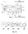
- Fig. 2is a block diagram illustrating certain additional features of a fluid reservoir, in accordance with certain exemplary implementations of the present invention.
- Fig. 3Ais a diagram illustrating certain features within a chamber of a fluid reservoir, in accordance with an exemplary implementation of the present invention.
- Fig. 3Bis a diagram illustrating a bag arranged within the chamber of the fluid reservoir in Fig. 3A , in accordance with an exemplary implementation of the present invention.
- Fig. 3Cis a diagram illustrating a resilient member arranged within the chamber of the fluid reservoir in Fig. 3B , in accordance with an exemplary implementation of the present invention.
- Fig. 3Dis a diagram illustrating the resilient member arranged within the chamber of the fluid reservoir in Fig. 3C with the bag deflated and compressed, in accordance with an exemplary implementation of the present invention.
- Fig. 3Eis a diagram illustrating the resilient member arranged within the chamber of the fluid reservoir in Fig. 3C with the bag significantly inflated, in accordance with an exemplary implementation of the present invention.
- Fig. 3Fis a cross-sectional view diagram illustrating a portion of the bag within the chamber of the fluid reservoir in Fig. 3E , in accordance with an exemplary implementation of the present invention.
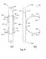
- Fig. 4is an isometric diagram illustrating certain features of a fluid reservoir in more detail, in accordance with certain exemplary implementations of the present invention.
- Fig. 5Ais an isometric diagram illustrating certain features of a multiple chamber fluid reservoir, in accordance with certain exemplary implementations of the present invention.
- Fig. 5Bis a top view diagram illustrating certain features within the multiple chamber fluid reservoir of Fig. 5A , in accordance with certain exemplary implementations of the present invention.
- Fig. 5Cis a cross-sectional diagram illustrating certain features within the multiple chamber fluid reservoir of Fig. 5B at line A-A, in accordance with certain exemplary implementations of the present invention.
- Fig. 5Dis an isometric diagram illustrating certain assembled features of a multiple chamber fluid reservoir including the insertion of a bag and spring therein, in accordance with certain exemplary implementations of the present invention.
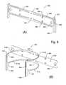
- Fig. 6Ais a top view diagram illustrating certain features of a bag as in Fig. 5D , in accordance with certain exemplary implementations of the present invention.
- Fig. 6Bis an isometric diagram illustrating certain features of a bag as in Fig. 5D , in accordance with certain exemplary implementations of the present invention.
- Fig. 6Cis a side view diagram illustrating certain features of a bag as in Figs. 6A-B , in accordance with certain exemplary implementations of the present invention.
- Fig. 7is an isometric diagram illustrating certain features of a crown that attached to the multiple chamber fluid reservoir of Fig. 5A , in accordance with certain exemplary implementations of the present invention.
- Figs. 8A-Bare isometric diagrams illustrating certain features of a spring as in Fig. 5D , in accordance with certain exemplary implementations of the present invention.
- Fig. 8Cis a front view diagram further illustrating the spring as in Figs. 8A-B , in accordance with certain exemplary implementations of the present invention.
- Fig. 8Dis a top side view diagram further illustrating the spring as in Figs. 8A-B , in accordance with certain exemplary implementations of the present invention.
- Figs. 9A-Care isometric diagrams illustrating certain techniques for forming a spring as in Figs. 8A-D , in accordance with certain exemplary implementations of the present invention.
- Figs. 10A-Dare diagrams illustrating certain techniques for forming a bag, in accordance with certain exemplary implementations of the present invention.
- Fig. 10Eis a diagram illustrating certain features of an inflated bag, as in Fig. 10D , in accordance with certain exemplary implementations of the present invention.
- Fig. 1is a block diagram illustrating certain features of a printing device 100 including a fluid reservoir 111, in accordance with certain exemplary implementations of the present invention.
- Printing device 100includes a fluid supply 102 containing a fluid 104.
- Fluid 104may include, by way of example, a printing related fluid such as an ink, a fixer, etc.
- Fluid supply 102is coupled to a conduit 106 that is coupled to a fluid delivery system 108.
- Fluid delivery system 108is configured to cause or otherwise allow fluid 104 to move to and from fluid supply 102 through conduit 106.
- Fluid delivery system 108is also configured to cause or otherwise allow air and/or air mixed with fluid (e.g., froth) to move to and from fluid supply 102 through conduit 106 at times.
- Fluid delivery system 108is also coupled to a conduit 110 which is further coupled to fluid reservoir 111. Fluid delivery system 108 is configured to cause or otherwise allow fluid 104 to move to and from fluid reservoir 111 through conduit 110. Fluid delivery system 108 is also configured to cause or otherwise allow air and/or air mixed with fluid to move to and from fluid reservoir 111 through conduit 110 at times.
- fluid delivery system 108may include one more pumps, valves or other like mechanisms and/or controls (not shown).
- fluid reservoir 111includes a chamber 112 that is configured to hold fluid 104 received through conduit 110.
- chamber 112Within chamber 112 are at least one inflatable bag 114 and a resilient member 116 that together provide a bag/spring accumulator that helps to maintain a desired backpressure within chamber 112.
- Fluid reservoir 111is further coupled to a conduit 118, which is further coupled to a fluid ejecting mechanism 120.
- fluid 104 within chamber 112is selectively drawn by fluid ejecting mechanism 120 through conduit 118.
- Fluid 104 drawn into fluid ejecting mechanism 120is then selectively ejected through one or more nozzles 122, for example, onto a print medium 124.
- Fluid 104 that is not ejectedmay be returned to fluid supply 102 along with any air, for example, by the action of fluid delivery system 108 via conduit 118, through fluid reservoir 111, through conduit 110, and through conduit 106 to fluid supply 102. In this manner, fluid 104 may be circulated and/or re-circulated though printing device 100, and/or air removed.
- conduits 110 and 118may each include one or more conduits.
- fluid reservoir 111, conduit 118 and fluid ejecting mechanism 122may be arranged on a carriage 126 that moves with respect to medium 124.
- fluid reservoirincludes a housing 200.
- a crown 202is attached to housing 200, such that housing 200 and crown 202 form chamber 112.
- chamber 112includes bag 114 and resilient member 116.
- Bag 114includes a fitment 204 that fluidically couples the interior of bag 114 to the atmosphere external to reservoir 111, represented by external air 226. Air 226 may change the volume occupied by bag 114 within chamber 112 through inflation and deflation.
- Resilient member 116is arranged to contact bag 114 and to apply compressive force to bag 114.
- a bubble port 206that is configured to allow external air 226 to enter into chamber 112 when a pressure difference between the external atmospheric pressure and the backpressure within chamber 112 reaches a threshold level.
- Air 226is illustrated entering into chamber 112 an air bubble 220, for example. As shown, air bubble 220 is directed from a first region 222 to a second region 224 within chamber 112 by a bubble director 208.
- bubble director 208is illustrated as directing air bubble 220 from bubble port 206 in first region 222 to second region 224 with air space 218.
- Bubble port 206 and bubble director 208are configured to help reduce the development of froth in chamber 112 by directing the air bubbles from first region 222 to second region 224 along a desired path rather than simply allowing the air bubbles to rise freely through fluid 104 at any time.
- first region 222 and second region 224will vary depending upon the design of fluid reservoir 111 and/or the type of fluid being used.
- the exemplary first and second regionsare "vertically" oriented with respect to one anther as between port bubbler 206 and air space 218 with bubble director 208 designed to direct the bubbles along a substantially straight path in the vertical direction.
- the first and second regionsmay have a different orientation to one another, and/or within the chamber.
- the regionsmay have a "horizontal" and/or “diagonal” orientation, and/or a more complex spatial arrangement and the bubble director in such implementations would be designed to direct bubbles along one or more desired paths from the first region to the second region.
- first regionis defined as a contiguous region of space within a chamber adjacent to a bubble port such that air or gas entering into the chamber through the bubble port enters into the first region and forms a bubble within the first region.
- second regionis defined as a region of space within the chamber that is separated from the bubble port by at least the first region.
- bubble 220is formed within the fluid 104 in the first region 222. Sometime after forming, bubble 220 rises and is forced or otherwise directed by bubble director 208 along a desired path to second region 224.
- a fluid outlet 210is configured to allow fluid 104 to pass through to fluid ejecting mechanism 120.
- a screen or filter 212is provided over fluid outlet 210. The use of such filters is well known.
- a port 214 into chamber 112is also provided, in this example through crown 202, such that fluid 104 (and/or air) may be introduced into and/or pulled out of chamber 112 by fluid delivery system 108.
- fluid bypass 216that, in this example, extends through housing 200 and crown 202 of fluid reservoir 111 that allows fluid delivery system to pull fluid and/or air from the fluid ejecting mechanism.
- Bubble port 206 and port 214may be located at or near the center of chamber, since reservoir 111 may be tilted.
- FIGs. 3A-Fare diagrams illustrating certain features within chamber 112, in accordance with certain exemplary implementations of the present invention.
- Fig. 3Ashows a view into the chamber portion provided by housing 200 prior to installing bag 114, resilient member 116 and attaching crown 202.
- bubble director 208is arranged at least partially along inner wall surface 228 of housing 200 above bubble port 206.
- Fluid outlet 210(in dashed line) is covered by filter 212.
- Fluid bypass 216extends through housing 200.
- a port 302extends through the floor of housing 200.
- port 302 and/or bubble port 206may also include a labyrinth or other like feature (not shown), as is well known.
- bag 114is coupled to port 302 using fitment 204.
- resilient member 116is arranged between inner wall surface 228 and bag 114.
- the arrows associated with resilient member 116 in these drawingsare intended to illustrate the expanding/compressive force provided by resilient member 116 between inner wall surface 228 and the side of bag 114 in contact with resilient member 116.
- bag 114is deflated enough such that the force of resilient member 116 on bag 114 has pushed bag 114 across chamber 112.
- resilient member 116is pushed back (compressed) by bag 114.
- bag 114is illustrated as being fully inflated and resilient member 116 fully compressed.
- bag 114is illustrated as being opaque such that only a bag opening 602 corresponding to fitment 204 and port 302 is visible in this cross-sectional view.
- FIG. 4is an isometric diagram illustrating certain features of exemplary bubble director 208 in more detail.
- bubble director 208includes two guides 402a-b that extend outwardly from inner surface wall 228 and define path 404.
- Guides 402a-btend to direct bubbles that enter through bubble port 206 along path 404.
- path 404is not fully enclosed until such time as contact occurs between part of resilient member 116 and/or bag 114, e.g., as illustrated in Figs. 3E-F , respectively.
- one or more guides 402may be used. In still other implementations, all or part of a guide 404 may be fully enclosed at all times.
- Guides 402may also provide a capillary function when reservoir 111 is inverted that allows bubble port 206 to stay wetted longer
- bubble director 208further includes a base 408 between guides 402a-b.
- base 408extends at least part of the way around and outwardly from bubble port 206.
- Base 408is also contoured in this example.
- the contour of base 408allows for a more conforming fit with the side of bag 114 when it comes into contact with bubble director 208.
- the contour of base 408may also be designed to help direct bubbles along and/or towards path 404, reduce the size of the first region, and/or help to keep bubble port 206 wetted (e.g., by holding some fluid next to bubble port 206 should reservoir 111 be inverted for time to time).
- base 408is separated from the bottom or floor surface of the chamber by a stage 406.
- stage 406may be needed to help form and/or support certain features of bubble port 206.
- bubble port 206includes a ball that fits into a shaped opening.
- a wetted conditioni.e., wet with fluid.
- at least one capillary feature 410may be provided to allow fluid to move past stage 406 and/or base 408.
- capillary feature 410extends through at least a part of base 408 as a groove therein and onto and over stage 406 as a protrusion into chamber 112 that contacts the floor surface. In this manner, capillary feature 410 is configured to draw fluid through capillary action to bubble port 206.
- base 408also includes a notch feature 514 that extends part way out and over bubbler port 206.
- Notch feature 514 in this exampleis configured to further assist capillary feature 410 in wetting bubble port 206.
- Notch feature 514may also be configured to further support the bubble directing feature provided by bubble director 208.
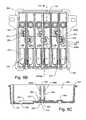
- FIG. 5Ais an isometric diagram illustrating certain features of a multiple chamber fluid reservoir housing 500, in accordance with certain further exemplary implementations of the present invention.
- Housing 500partially defines six separate chambers 112a-f, similar to those illustrated in Figs 3A-F and 4 .
- each chamber 112a-fmay be filled with a different color and/or type of ink.
- Housing 500includes an edge 502 is provided to attach to and/or otherwise mate with a corresponding surface 702 of a crown 700, such as shown in Fig. 7 .
- housing 500 and crown 700are formed of plastic and edge 502 and surface 702 are designed to be sealed together as result of thermal energy applied thereto.
- edge 502 and surface 702are designed to be sealed together as result of thermal energy applied thereto.
- other materialsmay be used to form housing 500 with crown 700 and/or other methods may be used to attach housing 500 and crown 700.
- Fig. 5Bis a top view diagram further illustrating features within the multiple chamber fluid reservoir housing 500.
- filter 212is illustrated here as being transparent.
- Fig. 5Cis a cross-sectional diagram illustrating some of the features within the multiple chamber fluid reservoir housing 500 of Fig. 5B at line A-A.
- ball 506is shown as being arranged in bubble port 206 in contact with a wall 510 having a desired shape that promotes bubble formation.
- Bubble port 206(before the ball is installed) may be used to initially fill chamber 112 with fluid, for example, during manufacture. This process is easier because the bag is collapsed and there is a lot of space for fill.
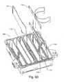
- Fig. 5Dis an isometric diagram illustrating multiple chamber fluid reservoir housing 500 during and after insertion of bag 114 and resilient member 116 (shown as a spring) therein, in accordance with certain exemplary implementations of the present invention.
- bag 114is installed in chamber 112e, for example by coupling fitment 204 with port 302.
- the spring (116)is then compressed and inserted in chamber 112e between bag 114 and the inner wall surface.
- chamber 112is about 10mm wide, 22mm high and 80mm long, and has an internal volume of about 15cc. Bag 114 occupies about 9cc when fully inflated. When deflated bag 114 occupies about 2cc. Thus, bag 114 can displace about 7cc of fluid 104. Bag 114 is inserted in a deflated state into chamber 112.
- Bag 114may be shorter than a length of chamber 112, but taller than a height of chamber 112. When inflated, bag 114 touches ceiling surface 708 of the crown 700. Because bag 114 touches ceiling surface 708, part of the volume of chamber 112 is occupied by bag rather than fluid. This tends to reduce the variation in fluid volume if reservoir 111 is tilted.
- FIGs. 10A-Dare diagrams illustrating certain techniques for forming a bag 114, in accordance with certain exemplary implementations of the present invention.
- a film or sheet 1000 of an air impermeable materialis shown.
- Sheet 1000may take varying shapes depending on the design of reservoir 111.
- Sheet 1000may include one or more layers of plastic and/or other like materials.
- Fig 10Bsheet 1000 is being folded in some manner such that at least a portion of a first side surface 1002 is brought into contact with itself.
- a second side surface 1004is shown as forming an outer surface.
- Sheet 1000now has a fold 608.
- the sheetis also joined together at a seam 604.
- portions of first side surface 1002may be heat bonded or otherwise attached together to form seam 604.
- Seam 604 in this exampleis contiguous and defines an interior 1006 of an inflatable bag 114 opposite fold 608, as illustrated in Fig. 10D .
- Fitment 204is heat bonded or otherwise attached to sheet 1000 along or near to fold 608.
- a bag opening 602extends through fitment 204 and through sheet 1000 into interior 1006.
- fitment 204is attached to sheet 1000 and bag opening 602 created prior folding the sheet.
- Fig. 10Eis a diagram illustrating certain features of the exemplary bag 114 of Fig. 10D inflated to a certain volume with air in this example, sheet 1000 includes materials that are substantially inelastic.
- bag 114inflates with air the shape of bag 114 and placement of fitment 204 along fold 608 causes a first end 612a and second end 612b to extend outwardly (as illustrated downwardly) from fitment 204.
- bag 114is configured such that ends 612a and/or 612b hold bag 114 off of the floor surface of the housing to keep bag 114 from interfering (e.g., blocking) filter 212.
- Fig. 6Ais a top view diagram illustrating certain features of a bag 114 shaped as in Fig. 5D , in accordance with certain exemplary implementations of the present invention.
- Bag 114has a tapered profile from this view and includes seam 604 and outer surface 606. Fitment 204 is attached along the fold as illustrated in the isometric diagram of Fig. 6B . Bag opening 602 extends through fitment 204 and into the interior of bag 114.
- seam 604includes several non-straight or curved portions 614, some of which create an indention 610.
- Indention 610may be configured to prevent bag 114 from blocking or otherwise interfering with other features of fluid reservoir 111. In this example, indention 610 prevents bag 114 from interfering with port 214.
- Fig. 7is an isometric diagram illustrating certain features of crown 700 that may be attached to the multiple chamber fluid reservoir housing 500 of Fig. 5A , for example, as previously described.
- crown 700For each chamber 112 in housing 500, crown 700 has a corresponding port 214 and fluid bypass opening 706 extending there through. Ridges 704 define chamber ceiling surfaces 708a-f, which correspond to chambers 112a-f of housing 500, respectively. Ridges 704 may be used to provide proper alignment and/or sealing of crown 700 to housing 500.
- FIGs. 8A-Bare isometric diagrams illustrating certain features of a resilient member 116 in the form of a spring 800, in accordance with certain exemplary implementations of the present invention.
- spring 800is formed of metal material such as a stainless steel or other alloy.
- spring 800is made using "301 Stainless Steel” that is about 0.16mm thick and has a minimum tensile strength of about 1,380 MPa (about 200,000 psi).
- other non-metallic materialse.g., plastic, etc. may be used to form all or part of a resilient member 116 having this and/or other shapes.
- Spring 800is shown as having a plurality of holes 802 and dimples 804, which are used to assist with the machining and/or manufacturing process. Accordingly, other implementations may have more, less, or no holes or dimples.
- two slots 806are formed by removing part of the material. As shown and described in more detail below, this exemplary slot 806 defines a beam portion and a plurality of leg portions. Also formed at this stage are two feet 808, two bridges 809 and two toes 810. Feet 808 and toes 810, which are shaped and bent protruding portions, are configured to position spring 800 within chamber 112. Feet 808 and bridge 809 are also configured (e.g., bent) to more easily slide along inner wall surface 228. One bridge 809 connects two legs together and is configured in this example to ease installation of spring 800 into chamber 112.
- spring 800has been shaped to be resilient as desired.
- four curved legs 812a-dextend outwardly from a center area in a direction away from inner surface 814.
- Each leg 812a-dhas a proximate end 824 and a distal end 822, and each leg portion 812a-d is tapered between the proximate and distal ends.
- the tapered shape of legs 812a-dis configured to allow spring 800 to provide a substantially consistent amount of force while operating in constrained region of chamber 112. Because the center of pressure of bag 114 is not in the center of the spring, in this example, legs 812c-d are slightly wider than legs 812a-b. This tends to reduce tilting of spring 800 as is moves in chamber 112.
- bridge 809which is optional, connects two legs at their distal ends 822.
- Fig. 8Cis a front view diagram further illustrating spring 800.
- center area 826is shown.
- toes 810 and feet 808extend outwardly to maintain the spring's position within chamber 112.
- toes 810may slidably contact ridge 704 of crown 700
- feet 808may slidably contact floor surface 512 of housing 500 to maintain spring 800 in position.
- An outer surface 816is shown in this view.
- Fig. 8Dis a top side view diagram of spring 800.
- This drawingillustrates that a beam portion 820 is provided and connected in the center area to proximate ends 824 of legs 812.
- Beam portion 820includes ends 818a and 818b.
- beam portion 820has been shaped to be resilient such that ends 818a and 818b each extend outwardly from the center area in a direction away from of the outer surface 816.
- the resilient shape of beam portion 820is configured to allow for a more even compressive force to be applied by spring 800 across the length of beam portion 820 and bag 114.
- Figs. 9A-Cillustrate one technique for shaping the legs 812 of spring 800 to be resilient, in accordance with certain exemplary implementations of the present invention.
- Spring 800in this example, may be referred to as a constant-stress/constant-radius cantilever beam spring.
- the legsmay be shaped using a form or tool 900 as in Fig. 9A .
- a fist half of spring 800e.g., flat as in Fig. 8A
- mandrel 902.As shown, the tool and mandrel compressively contact the leg portions, but not the beam portion.
- a pulling force represented by arrow 904is then applied to spring 800 that causes the leg portions to bend and become resilient as it is conformed by tool 900 and mandrel 902. The process is then repeated for the other half of spring 800.
- the resulting unitary member, parabolic cantilever beam spring 800is shown in Fig. 9C .
Landscapes
- Ink Jet (AREA)
- Pens And Brushes (AREA)
Abstract
Description
- Some printing devices need to pump or otherwise move inks or other fluids between various components during printing and/or maintenance processes. A fluid reservoir component is often configured to provide the ink or fluid to a fluid ejection mechanism, such as an inkjet printhead. The movement of fluid and air into and out of the fluid reservoir can lead to the formation of froth, which can reduce the effectiveness of the fluid delivery system and possibly affect printing.
EP 1 020 293 A1 describes an ink supply is contained in a manner that combines foam and free ink storage to provide high volumetric efficiency, back pressure regulation to protect against ink leakage, and a generally lower cost, easy-to-manufacture assembly. Ink leakage protection is present despite exposure of the supply to substantial variations in temperature and ambient air pressure. The container is divided, and part of the container includes porous material for storing ink. Capillary pressures of the material and of a bubble generator in the free-ink part of the container are selected to control the sequence with which ink is removed from the container parts.- It is an object of the invention to provide an improved fluid reservoir that allows for adequate fluid/air flow while avoiding, or otherwise reducing, the formation of froth therein.
- This object is achieved by a fluid reservoir of claim 1.
- The following detailed description refers to the accompanying figures.
Fig. 1 is a block diagram illustrating certain features of a printing device including fluid reservoir, in accordance with certain exemplary implementations of the present invention.Fig. 2 is a block diagram illustrating certain additional features of a fluid reservoir, in accordance with certain exemplary implementations of the present invention.Fig. 3A is a diagram illustrating certain features within a chamber of a fluid reservoir, in accordance with an exemplary implementation of the present invention.Fig. 3B is a diagram illustrating a bag arranged within the chamber of the fluid reservoir inFig. 3A , in accordance with an exemplary implementation of the present invention.Fig. 3C is a diagram illustrating a resilient member arranged within the chamber of the fluid reservoir inFig. 3B , in accordance with an exemplary implementation of the present invention.Fig. 3D is a diagram illustrating the resilient member arranged within the chamber of the fluid reservoir inFig. 3C with the bag deflated and compressed, in accordance with an exemplary implementation of the present invention.Fig. 3E is a diagram illustrating the resilient member arranged within the chamber of the fluid reservoir inFig. 3C with the bag significantly inflated, in accordance with an exemplary implementation of the present invention.Fig. 3F is a cross-sectional view diagram illustrating a portion of the bag within the chamber of the fluid reservoir inFig. 3E , in accordance with an exemplary implementation of the present invention.Fig. 4 is an isometric diagram illustrating certain features of a fluid reservoir in more detail, in accordance with certain exemplary implementations of the present invention.Fig. 5A is an isometric diagram illustrating certain features of a multiple chamber fluid reservoir, in accordance with certain exemplary implementations of the present invention.Fig. 5B is a top view diagram illustrating certain features within the multiple chamber fluid reservoir ofFig. 5A , in accordance with certain exemplary implementations of the present invention.Fig. 5C is a cross-sectional diagram illustrating certain features within the multiple chamber fluid reservoir ofFig. 5B at line A-A, in accordance with certain exemplary implementations of the present invention.Fig. 5D is an isometric diagram illustrating certain assembled features of a multiple chamber fluid reservoir including the insertion of a bag and spring therein, in accordance with certain exemplary implementations of the present invention.Fig. 6A is a top view diagram illustrating certain features of a bag as inFig. 5D , in accordance with certain exemplary implementations of the present invention.Fig. 6B is an isometric diagram illustrating certain features of a bag as inFig. 5D , in accordance with certain exemplary implementations of the present invention.Fig. 6C is a side view diagram illustrating certain features of a bag as inFigs. 6A-B , in accordance with certain exemplary implementations of the present invention.Fig. 7 is an isometric diagram illustrating certain features of a crown that attached to the multiple chamber fluid reservoir ofFig. 5A , in accordance with certain exemplary implementations of the present invention.Figs. 8A-B are isometric diagrams illustrating certain features of a spring as inFig. 5D , in accordance with certain exemplary implementations of the present invention.Fig. 8C is a front view diagram further illustrating the spring as inFigs. 8A-B , in accordance with certain exemplary implementations of the present invention.Fig. 8D is a top side view diagram further illustrating the spring as inFigs. 8A-B , in accordance with certain exemplary implementations of the present invention.Figs. 9A-C are isometric diagrams illustrating certain techniques for forming a spring as inFigs. 8A-D , in accordance with certain exemplary implementations of the present invention.Figs. 10A-D are diagrams illustrating certain techniques for forming a bag, in accordance with certain exemplary implementations of the present invention.Fig. 10E is a diagram illustrating certain features of an inflated bag, as inFig. 10D , in accordance with certain exemplary implementations of the present invention.Fig. 1 is a block diagram illustrating certain features of aprinting device 100 including afluid reservoir 111, in accordance with certain exemplary implementations of the present invention.Printing device 100 includes afluid supply 102 containing a fluid 104.Fluid 104 may include, by way of example, a printing related fluid such as an ink, a fixer, etc.Fluid supply 102 is coupled to aconduit 106 that is coupled to afluid delivery system 108.Fluid delivery system 108 is configured to cause or otherwise allow fluid 104 to move to and fromfluid supply 102 throughconduit 106.Fluid delivery system 108 is also configured to cause or otherwise allow air and/or air mixed with fluid (e.g., froth) to move to and fromfluid supply 102 throughconduit 106 at times.Fluid delivery system 108 is also coupled to aconduit 110 which is further coupled tofluid reservoir 111.Fluid delivery system 108 is configured to cause or otherwise allow fluid 104 to move to and fromfluid reservoir 111 throughconduit 110.Fluid delivery system 108 is also configured to cause or otherwise allow air and/or air mixed with fluid to move to and fromfluid reservoir 111 throughconduit 110 at times.- Those skilled in the art will recognize that
fluid delivery system 108 may include one more pumps, valves or other like mechanisms and/or controls (not shown). - In this example,
fluid reservoir 111 includes achamber 112 that is configured to hold fluid 104 received throughconduit 110. Withinchamber 112 are at least oneinflatable bag 114 and aresilient member 116 that together provide a bag/spring accumulator that helps to maintain a desired backpressure withinchamber 112. Fluid reservoir 111 is further coupled to aconduit 118, which is further coupled to afluid ejecting mechanism 120. During printing,fluid 104 withinchamber 112 is selectively drawn byfluid ejecting mechanism 120 throughconduit 118.Fluid 104 drawn intofluid ejecting mechanism 120 is then selectively ejected through one ormore nozzles 122, for example, onto aprint medium 124.Fluid 104 that is not ejected may be returned tofluid supply 102 along with any air, for example, by the action offluid delivery system 108 viaconduit 118, throughfluid reservoir 111, throughconduit 110, and throughconduit 106 tofluid supply 102. In this manner, fluid 104 may be circulated and/or re-circulated thoughprinting device 100, and/or air removed.- In this example,
conduits - As further illustrated in
Fig. 1 ,fluid reservoir 111,conduit 118 andfluid ejecting mechanism 122 may be arranged on acarriage 126 that moves with respect tomedium 124. - Attention is now drawn to
Fig. 2 , which is a block diagram illustrating certain additional features offluid reservoir 111. Here, fluid reservoir includes ahousing 200. Acrown 202 is attached tohousing 200, such thathousing 200 andcrown 202form chamber 112. As inFig. 1 ,chamber 112 includesbag 114 andresilient member 116.Bag 114 includes afitment 204 that fluidically couples the interior ofbag 114 to the atmosphere external toreservoir 111, represented byexternal air 226.Air 226 may change the volume occupied bybag 114 withinchamber 112 through inflation and deflation.Resilient member 116 is arranged to contactbag 114 and to apply compressive force tobag 114. - Within
chamber 112 there is abubble port 206 that is configured to allowexternal air 226 to enter intochamber 112 when a pressure difference between the external atmospheric pressure and the backpressure withinchamber 112 reaches a threshold level.Air 226 is illustrated entering intochamber 112 anair bubble 220, for example. As shown,air bubble 220 is directed from afirst region 222 to asecond region 224 withinchamber 112 by abubble director 208. - Here, for example,
bubble director 208 is illustrated as directingair bubble 220 frombubble port 206 infirst region 222 tosecond region 224 withair space 218. The introduction of air bubbles intochamber 112 viabubbler port 206, during certain active fluid movement cycles in which fluid is moved into and/or out ofchamber 112, may lead to unwanted levels of froth or foam being generated withinchamber 112.Bubble port 206 andbubble director 208 are configured to help reduce the development of froth inchamber 112 by directing the air bubbles fromfirst region 222 tosecond region 224 along a desired path rather than simply allowing the air bubbles to rise freely throughfluid 104 at any time. - Those skilled in the art will recognize that the delineation between
first region 222 andsecond region 224 will vary depending upon the design offluid reservoir 111 and/or the type of fluid being used. - In the example shown in
Fig. 2 , the exemplary first and second regions are "vertically" oriented with respect to one anther as betweenport bubbler 206 andair space 218 withbubble director 208 designed to direct the bubbles along a substantially straight path in the vertical direction. In other implementations, the first and second regions may have a different orientation to one another, and/or within the chamber. For example, the regions may have a "horizontal" and/or "diagonal" orientation, and/or a more complex spatial arrangement and the bubble director in such implementations would be designed to direct bubbles along one or more desired paths from the first region to the second region. - As used herein, the term "first region" is defined as a contiguous region of space within a chamber adjacent to a bubble port such that air or gas entering into the chamber through the bubble port enters into the first region and forms a bubble within the first region. The term "second region" as used herein is defined as a region of space within the chamber that is separated from the bubble port by at least the first region.
- Hence,
bubble 220 is formed within the fluid 104 in thefirst region 222. Sometime after forming,bubble 220 rises and is forced or otherwise directed bybubble director 208 along a desired path tosecond region 224. - As shown in
Fig. 2 , afluid outlet 210 is configured to allow fluid 104 to pass through tofluid ejecting mechanism 120. Here, a screen or filter 212 is provided overfluid outlet 210. The use of such filters is well known. - A
port 214 intochamber 112 is also provided, in this example throughcrown 202, such that fluid 104 (and/or air) may be introduced into and/or pulled out ofchamber 112 byfluid delivery system 108. There is also afluid bypass 216 that, in this example, extends throughhousing 200 andcrown 202 offluid reservoir 111 that allows fluid delivery system to pull fluid and/or air from the fluid ejecting mechanism.Bubble port 206 andport 214 may be located at or near the center of chamber, sincereservoir 111 may be tilted. Figs. 3A-F are diagrams illustrating certain features withinchamber 112, in accordance with certain exemplary implementations of the present invention.Fig. 3A shows a view into the chamber portion provided byhousing 200 prior to installingbag 114,resilient member 116 and attachingcrown 202. As shown,bubble director 208 is arranged at least partially alonginner wall surface 228 ofhousing 200 abovebubble port 206. Fluid outlet 210 (in dashed line) is covered byfilter 212.Fluid bypass 216 extends throughhousing 200. Aport 302 extends through the floor ofhousing 200.- In the examples illustrated herein,
port 302 and/orbubble port 206 may also include a labyrinth or other like feature (not shown), as is well known. - In
Fig. 3B bag 114 is coupled toport 302 usingfitment 204. InFig. 3C resilient member 116 is arranged betweeninner wall surface 228 andbag 114. The arrows associated withresilient member 116 in these drawings are intended to illustrate the expanding/compressive force provided byresilient member 116 betweeninner wall surface 228 and the side ofbag 114 in contact withresilient member 116. Thus, for example, inFig. 3D bag 114 is deflated enough such that the force ofresilient member 116 onbag 114 has pushedbag 114 acrosschamber 112. To the contrary, whenbag 114 is inflated, as illustrated inFig. 3E ,resilient member 116 is pushed back (compressed) bybag 114. In this example,bag 114 is illustrated as being fully inflated andresilient member 116 fully compressed. - As shown, when fully compressed part of
resilient member 116 contacts part ofbubble director 208. Even with such contact,bubble director 116 maintains apath 404 between the first and second regions. Indeed, in this example,path 404 is actually at least partially enclosed byresilient member 116. As illustrated using a cross-sectional view inFig. 3F , part ofbag 114 also contacts part ofbubble director 208. Again, even with such contact,bubble director 208 maintains apath 404 between the first and second regions.Path 404 may therefore be at least partially enclosed bybag 114. - Note that in
Fig. 3F ,bag 114 is illustrated as being opaque such that only abag opening 602 corresponding to fitment 204 andport 302 is visible in this cross-sectional view. - Attention is now drawn to
Fig. 4 , which is an isometric diagram illustrating certain features ofexemplary bubble director 208 in more detail. - In this example,
bubble director 208 includes twoguides 402a-b that extend outwardly frominner surface wall 228 and definepath 404.Guides 402a-b tend to direct bubbles that enter throughbubble port 206 alongpath 404. Here,path 404 is not fully enclosed until such time as contact occurs between part ofresilient member 116 and/orbag 114, e.g., as illustrated inFigs. 3E-F , respectively. - In other implementations, one or more guides 402 may be used. In still other implementations, all or part of a
guide 404 may be fully enclosed at all times. - Guides 402 may also provide a capillary function when
reservoir 111 is inverted that allowsbubble port 206 to stay wetted longer - In
Fig. 4 ,bubble director 208 further includes a base 408 betweenguides 402a-b. In this example,base 408 extends at least part of the way around and outwardly frombubble port 206.Base 408 is also contoured in this example. Here, the contour ofbase 408 allows for a more conforming fit with the side ofbag 114 when it comes into contact withbubble director 208. The contour ofbase 408 may also be designed to help direct bubbles along and/or towardspath 404, reduce the size of the first region, and/or help to keepbubble port 206 wetted (e.g., by holding some fluid next tobubble port 206 shouldreservoir 111 be inverted for time to time). - In this example,
base 408 is separated from the bottom or floor surface of the chamber by astage 406. For example,stage 406 may be needed to help form and/or support certain features ofbubble port 206. - In certain implementations,
bubble port 206 includes a ball that fits into a shaped opening. To function properly the interface between the ball and the opening's wall should be maintained in a wetted condition (i.e., wet with fluid). As shown inFig. 4 , to help further help maintain bubble port in a wetted condition, at least onecapillary feature 410 may be provided to allow fluid to movepast stage 406 and/orbase 408. Here,capillary feature 410 extends through at least a part ofbase 408 as a groove therein and onto and overstage 406 as a protrusion intochamber 112 that contacts the floor surface. In this manner,capillary feature 410 is configured to draw fluid through capillary action tobubble port 206. - In the example shown in
Fig 4 ,base 408 also includes anotch feature 514 that extends part way out and overbubbler port 206.Notch feature 514 in this example is configured to further assistcapillary feature 410 in wettingbubble port 206.Notch feature 514 may also be configured to further support the bubble directing feature provided bybubble director 208. - Attention is now drawn to
Fig. 5A , which is an isometric diagram illustrating certain features of a multiple chamberfluid reservoir housing 500, in accordance with certain further exemplary implementations of the present invention. Housing 500 partially defines sixseparate chambers 112a-f, similar to those illustrated inFigs 3A-F and4 . Here, for example, when used in a multiple color inkjet printer, eachchamber 112a-f may be filled with a different color and/or type of ink.Housing 500 includes anedge 502 is provided to attach to and/or otherwise mate with acorresponding surface 702 of acrown 700, such as shown inFig. 7 . In this example,housing 500 andcrown 700 are formed of plastic andedge 502 andsurface 702 are designed to be sealed together as result of thermal energy applied thereto. Those skilled in the art will recognize that other materials may be used to formhousing 500 withcrown 700 and/or other methods may be used to attachhousing 500 andcrown 700.Fig. 5B is a top view diagram further illustrating features within the multiple chamberfluid reservoir housing 500. Here, for example,filter 212 is illustrated here as being transparent.Fig. 5C is a cross-sectional diagram illustrating some of the features within the multiple chamberfluid reservoir housing 500 ofFig. 5B at line A-A. Here,ball 506 is shown as being arranged inbubble port 206 in contact with awall 510 having a desired shape that promotes bubble formation.- Bubble port 206 (before the ball is installed) may be used to initially fill
chamber 112 with fluid, for example, during manufacture. This process is easier because the bag is collapsed and there is a lot of space for fill. Fig. 5D is an isometric diagram illustrating multiple chamberfluid reservoir housing 500 during and after insertion ofbag 114 and resilient member 116 (shown as a spring) therein, in accordance with certain exemplary implementations of the present invention. As illustrated by the directional arrows,bag 114 is installed inchamber 112e, for example by couplingfitment 204 withport 302. The spring (116) is then compressed and inserted inchamber 112e betweenbag 114 and the inner wall surface.- In one example,
chamber 112 is about 10mm wide, 22mm high and 80mm long, and has an internal volume of about 15cc.Bag 114 occupies about 9cc when fully inflated. When deflatedbag 114 occupies about 2cc. Thus,bag 114 can displace about 7cc offluid 104.Bag 114 is inserted in a deflated state intochamber 112. Bag 114 may be shorter than a length ofchamber 112, but taller than a height ofchamber 112. When inflated,bag 114 touches ceiling surface 708 of thecrown 700. Becausebag 114 touches ceiling surface 708, part of the volume ofchamber 112 is occupied by bag rather than fluid. This tends to reduce the variation in fluid volume ifreservoir 111 is tilted.- Attention is drawn next to
Figs. 10A-D , which are diagrams illustrating certain techniques for forming abag 114, in accordance with certain exemplary implementations of the present invention. - In
Fig. 10A , a film orsheet 1000 of an air impermeable material is shown.Sheet 1000 may take varying shapes depending on the design ofreservoir 111.Sheet 1000 may include one or more layers of plastic and/or other like materials. - In
Fig 10B ,sheet 1000 is being folded in some manner such that at least a portion of afirst side surface 1002 is brought into contact with itself. InFig. 10C , asecond side surface 1004 is shown as forming an outer surface.Sheet 1000 now has afold 608. The sheet is also joined together at aseam 604. For example, portions offirst side surface 1002 may be heat bonded or otherwise attached together to formseam 604. Seam 604 in this example is contiguous and defines an interior 1006 of aninflatable bag 114opposite fold 608, as illustrated inFig. 10D .Fitment 204 is heat bonded or otherwise attached tosheet 1000 along or near to fold 608. A bag opening 602 (seeFig. 3F andFig. 6B ) extends throughfitment 204 and throughsheet 1000 into interior 1006. In certain implementations,fitment 204 is attached tosheet 1000 andbag opening 602 created prior folding the sheet.Fig. 10E is a diagram illustrating certain features of theexemplary bag 114 ofFig. 10D inflated to a certain volume with air in this example,sheet 1000 includes materials that are substantially inelastic. Thus, asbag 114 inflates with air the shape ofbag 114 and placement offitment 204 alongfold 608 causes afirst end 612a andsecond end 612b to extend outwardly (as illustrated downwardly) fromfitment 204. In certain implementations,bag 114 is configured such that ends 612a and/or 612b holdbag 114 off of the floor surface of the housing to keepbag 114 from interfering (e.g., blocking)filter 212.Fig. 6A is a top view diagram illustrating certain features of abag 114 shaped as inFig. 5D , in accordance with certain exemplary implementations of the present invention.Bag 114 has a tapered profile from this view and includesseam 604 andouter surface 606.Fitment 204 is attached along the fold as illustrated in the isometric diagram ofFig. 6B .Bag opening 602 extends throughfitment 204 and into the interior ofbag 114.- As further illustrated in the side view diagram of
Fig. 6C ,seam 604 includes several non-straight orcurved portions 614, some of which create anindention 610.Indention 610, for example, may be configured to preventbag 114 from blocking or otherwise interfering with other features offluid reservoir 111. In this example,indention 610 preventsbag 114 from interfering withport 214. Fig. 7 is an isometric diagram illustrating certain features ofcrown 700 that may be attached to the multiple chamberfluid reservoir housing 500 ofFig. 5A , for example, as previously described.- For each
chamber 112 inhousing 500,crown 700 has acorresponding port 214 andfluid bypass opening 706 extending there through.Ridges 704 definechamber ceiling surfaces 708a-f, which correspond tochambers 112a-f ofhousing 500, respectively.Ridges 704 may be used to provide proper alignment and/or sealing ofcrown 700 tohousing 500. - Attention is drawn now to
Figs. 8A-B , which are isometric diagrams illustrating certain features of aresilient member 116 in the form of aspring 800, in accordance with certain exemplary implementations of the present invention. - In
Fig. 8A , a stamped and partially formed unitary piece of material is shown prior to being shaped to be resilient as desired. In certain implementations,spring 800 is formed of metal material such as a stainless steel or other alloy. By way of example, incertain implementations spring 800 is made using "301 Stainless Steel" that is about 0.16mm thick and has a minimum tensile strength of about 1,380 MPa (about 200,000 psi). In other implementations, other non-metallic materials (e.g., plastic, etc.) may be used to form all or part of aresilient member 116 having this and/or other shapes. Spring 800 is shown as having a plurality ofholes 802 anddimples 804, which are used to assist with the machining and/or manufacturing process. Accordingly, other implementations may have more, less, or no holes or dimples.- In this example, two
slots 806 are formed by removing part of the material. As shown and described in more detail below, thisexemplary slot 806 defines a beam portion and a plurality of leg portions. Also formed at this stage are twofeet 808, twobridges 809 and twotoes 810.Feet 808 andtoes 810, which are shaped and bent protruding portions, are configured to positionspring 800 withinchamber 112.Feet 808 andbridge 809 are also configured (e.g., bent) to more easily slide alonginner wall surface 228. Onebridge 809 connects two legs together and is configured in this example to ease installation ofspring 800 intochamber 112. - In
Fig. 8B ,spring 800 has been shaped to be resilient as desired. As shown in this example fourcurved legs 812a-d extend outwardly from a center area in a direction away frominner surface 814. Eachleg 812a-d has aproximate end 824 and adistal end 822, and eachleg portion 812a-d is tapered between the proximate and distal ends. The tapered shape oflegs 812a-d is configured to allowspring 800 to provide a substantially consistent amount of force while operating in constrained region ofchamber 112. Because the center of pressure ofbag 114 is not in the center of the spring, in this example,legs 812c-d are slightly wider thanlegs 812a-b. This tends to reduce tilting ofspring 800 as is moves inchamber 112. - As shown
bridge 809, which is optional, connects two legs at their distal ends 822. Fig. 8C is a front view diagram further illustratingspring 800. Here,center area 826 is shown. From this view point, it can be seen thattoes 810 andfeet 808 extend outwardly to maintain the spring's position withinchamber 112. For example,toes 810 may slidably contactridge 704 ofcrown 700, andfeet 808 may slidably contactfloor surface 512 ofhousing 500 to maintainspring 800 in position. Anouter surface 816 is shown in this view.Fig. 8D is a top side view diagram ofspring 800. This drawing illustrates that abeam portion 820 is provided and connected in the center area toproximate ends 824 oflegs 812.Beam portion 820 includesends beam portion 820 has been shaped to be resilient such that ends 818a and 818b each extend outwardly from the center area in a direction away from of theouter surface 816. The resilient shape ofbeam portion 820 is configured to allow for a more even compressive force to be applied byspring 800 across the length ofbeam portion 820 andbag 114.Figs. 9A-C illustrate one technique for shaping thelegs 812 ofspring 800 to be resilient, in accordance with certain exemplary implementations of the present invention.Spring 800, in this example, may be referred to as a constant-stress/constant-radius cantilever beam spring. The legs may be shaped using a form ortool 900 as inFig. 9A . As shown inFig. 9B , a fist half of spring 800 (e.g., flat as inFig. 8A ) is inserted intotool 900 followed by amandrel 902. As shown, the tool and mandrel compressively contact the leg portions, but not the beam portion. A pulling force represented byarrow 904 is then applied tospring 800 that causes the leg portions to bend and become resilient as it is conformed bytool 900 andmandrel 902. The process is then repeated for the other half ofspring 800. The resulting unitary member, paraboliccantilever beam spring 800 is shown inFig. 9C .
Claims (9)
- A fluid reservoir (111) for use in a printing device (100) comprising:a housing (200, 500) at least partially forming at least one chamber (112) therein that is configured to hold a fluid (104);an inflatable bag (114) arranged within said chamber (112);a resilient member (116) arranged within said chamber (112) and configured to compressively contact said inflatable bag (114);a bubble port (206) leading through said housing (200, 500) into a first region (222) of said chamber (112) and fluidically coupling said chamber (112) to atmospheric gas (226) external to said housing (200, 500); anda bubble director (208) arranged within said chamber (112) at least partially arranged on an inner wall surface (228) of said housing (200, 500) above said bubble port (206) and configured to direct at least one bubble (220) of said gas (226) from said first region (222) to a second region (224) of said chamber (112), said bubble (220) being formed within said fluid (104) within said first region (222) upon said gas (226) entering said chamber (112) through said bubble port (206),wherein said bubble director (208) maintains a path (404) between said first and second regions (222, 224), and said path (404) is at least partially enclosed by said inflatable bag (114) and said resilient member (116) when said inflatable bag (114) is fully inflated and said resilient member (116) is fully compressed.
- The fluid reservoir (111) as recited in Claim 1, wherein said housing (200, 500) further includes a port (302) leading through said housing, said fluid reservoir (111), and wherein said inflatable bag (114) has a fitment (204) fluidically coupled to receive said gas (226) through said port (302).
- The fluid reservoir (111) as recited in Claim 1 or 2, wherein said bubble director (208) includes two guides (402a-b) on said inner wall surface (228) extending from said first region (222) to said second region (224), said two guides (402a-b) forming a path (404) there between.
- The fluid reservoir (111) as recited in Claim 3, wherein said guides (402a-b) are configured to contact said resilient member (116) and said inflatable bag (114) when inflatable bag (114) is inflated to form at least part of an enclosed path (404).
- The fluid reservoir (111) as recited in Claim 3, said bubble director (208) further comprising a base (408) surrounding said bubble port(206), said base (408) being in said first region (222) and shaped to direct said air bubble (220) towards said guide (402), wherein said base (408) includes at least one capillary feature (410) formed therein that is configured to direct said fluid (104) to bubble port (206).
- The fluid reservoir (111) as recited in Claim 1, said resilient member (116) comprising at least one cantilever beam spring (800).
- The fluid reservoir (111) as recited in Claim 1, said inflatable bag (114) comprising:a sheet (1000) of at least one air impermeable plastic material having a first side surface (1002) and a second side surface (1004) wherein said sheet includes a fold (608) and portions of said first side surface are joined together to form a seam (604) that is contiguous and defines an interior (1006) of the inflatable bag (114) opposite said fold (608);a bag opening (602) positioned along said fold (608) interior a first end (612a) and a second end (612b);said fitment (204) attached to said bag opening (602), and wherein said opposing fold (608) and seam (604) are shaped such that when the inflatable bag (114) inflates with air said first and second ends (612a, 612b) extend outwardly from said fitment (204).
- The fluid reservoir (111) as recited in Claim 1, said resilient member (116) comprising a spring (800) having a beam portion (820) having a first end (818a), a second end (818b), a center area (826) an inner surface (814), and an outer surface (816), and a plurality of curved leg portions (812), each leg portion (812) being shaped to be resilient and extending outwardly from said center area (826) in a direction away from said inner surface (814) and having a proximate end (824) to a distal end (822), and wherein at least a part of each leg portion (812) is tapered between said proximate and distal ends (824 and 822).
- A method for use in a fluid reservoir (111) as recited in one of claims 1 to 8, the method comprising:causing said inflatable bag (114) that is under compression by said resilient member (116) to inflate until said inflatable bag (114) is fully inflated and said resilient member (116) is fully compressed so that said path (404) is at least partially enclosed by said inflatable bag (114) and said resilient member (116); anddirecting at least one air bubble (220) from said first region (222) of said chamber (112) to said second region (224) of said chamber (112) using said path (404).
Applications Claiming Priority (2)
| Application Number | Priority Date | Filing Date | Title |
|---|---|---|---|
| US11/173,779US7762651B2 (en) | 2005-06-30 | 2005-06-30 | Printing device fluid reservoir |
| PCT/US2006/023861WO2007005265A1 (en) | 2005-06-30 | 2006-06-19 | Printing device fluid reservoir |
Publications (2)
| Publication Number | Publication Date |
|---|---|
| EP1907214A1 EP1907214A1 (en) | 2008-04-09 |
| EP1907214B1true EP1907214B1 (en) | 2011-12-28 |
Family
ID=37027494
Family Applications (1)
| Application Number | Title | Priority Date | Filing Date |
|---|---|---|---|
| EP06773565ANot-in-forceEP1907214B1 (en) | 2005-06-30 | 2006-06-19 | Printing device fluid reservoir |
Country Status (10)
| Country | Link |
|---|---|
| US (2) | US7762651B2 (en) |
| EP (1) | EP1907214B1 (en) |
| JP (1) | JP4695189B2 (en) |
| KR (1) | KR20080020648A (en) |
| CN (1) | CN101223035B (en) |
| AT (1) | ATE538936T1 (en) |
| BR (1) | BRPI0613350B1 (en) |
| CA (1) | CA2613829C (en) |
| SG (1) | SG163541A1 (en) |
| WO (1) | WO2007005265A1 (en) |
Families Citing this family (4)
| Publication number | Priority date | Publication date | Assignee | Title |
|---|---|---|---|---|
| KR101855968B1 (en)* | 2011-01-07 | 2018-05-09 | 휴렛-팩커드 디벨롭먼트 컴퍼니, 엘.피. | Fluid container having plurality of chambers and valves |
| US8491075B2 (en) | 2011-02-09 | 2013-07-23 | Xerox Corporation | Method and apparatus for controlling jetting performance in an inkjet printer |
| WO2020222834A1 (en)* | 2019-04-30 | 2020-11-05 | Hewlett-Packard Development Company, L.P. | Fluid ejection and circulation |
| WO2022046099A1 (en)* | 2020-08-31 | 2022-03-03 | Hewlett-Packard Development Company, L.P. | Sealed bag to temporarily expand and receive fluid that would otherwise drool during an exceptional drooling event |
Family Cites Families (36)
| Publication number | Priority date | Publication date | Assignee | Title |
|---|---|---|---|---|
| CH340046A (en)* | 1956-05-28 | 1959-07-31 | Oerlikon Buehrle Ag | Process for the production of tubes from thermoplastic material |
| US4394936A (en)* | 1981-10-14 | 1983-07-26 | Henri Shavit | Deformable container and a flat piece for making a container |
| US5745137A (en) | 1992-08-12 | 1998-04-28 | Hewlett-Packard Company | Continuous refill of spring bag reservoir in an ink-jet swath printer/plotter |
| US5903292A (en) | 1991-06-19 | 1999-05-11 | Hewlett-Packard Company | Ink refill techniques for an inkjet print cartridge which leave correct back pressure |
| USD344888S (en)* | 1992-01-20 | 1994-03-08 | Norden Pac Development Ab | Tube |
| US5325119A (en) | 1992-08-12 | 1994-06-28 | Hewlett-Packard Company | Variable rate spring ink pressure regulator for a thermal ink jet printer |
| CA2093971A1 (en) | 1992-08-12 | 1994-02-13 | Tofigh Khodapanah | Ink pressure regulator for a thermal ink jet printer |
| US6164825A (en)* | 1996-11-26 | 2000-12-26 | The Coca-Cola Company | Stable, flexible, easy open pouch |
| USD402366S (en)* | 1997-05-19 | 1998-12-08 | B. Braun Medical, Inc. | Flexible, multiple compartment medical container |
| US5988803A (en) | 1997-12-12 | 1999-11-23 | Lexmark International, Inc. | Ink leakage control arrangement for an ink cartridge |
| JP4585635B2 (en)* | 1998-09-16 | 2010-11-24 | 亘起物産有限会社 | Enteral nutrient and drinking water storage container and connecting member thereof |
| US6505924B2 (en) | 1998-09-30 | 2003-01-14 | Brother Kogyo Kabushiki Kaisha | Ink cartridge |
| US6186621B1 (en) | 1999-01-12 | 2001-02-13 | Hewlett-Packard Company | Volumetrically efficient printer ink supply combining foam and free ink storage |
| US6186620B1 (en)* | 1999-02-12 | 2001-02-13 | Industrial Technology Research Institute | Ink pressure control apparatus for ink-jet pens |
| TW394176U (en) | 1999-08-11 | 2000-06-11 | Microjet Technology Co Ltd | Pressure regulating mechanism |
| US6540341B2 (en)* | 2000-01-29 | 2003-04-01 | Industrial Technology Research Institute | Pressure controller for an ink cartridge |
| US6406124B1 (en) | 2000-01-31 | 2002-06-18 | Hewlett-Packard Company | Ganged inkjet printhead capping system |
| CN1188284C (en)* | 2001-12-11 | 2005-02-09 | 珠海天威飞马打印耗材有限公司 | Ink-cases of printers |
| KR100389444B1 (en)* | 2000-04-11 | 2003-06-27 | 세이코 엡슨 가부시키가이샤 | Ink cartridge for recording apparatus |
| CN1158183C (en)* | 2000-10-12 | 2004-07-21 | 珠海飞马耗材有限公司 | Ink cartridge for ink jetting record equipment |
| TW505572B (en)* | 2000-10-20 | 2002-10-11 | Internat United Technoloy Co L | Ink container with pressure regulation device |
| TW562750B (en) | 2000-12-05 | 2003-11-21 | Benq Corp | Pressure-compensation device |
| TW528684B (en) | 2000-12-08 | 2003-04-21 | Benq Corp | Pressure regulating device of ink cartridge for an ink-jet printer |
| TW541248B (en)* | 2001-03-16 | 2003-07-11 | Benq Corp | Ink cartridge |
| KR100403600B1 (en) | 2001-12-20 | 2003-10-30 | 삼성전자주식회사 | Ink cartridge and ink jet printer having the same |
| TW526817U (en)* | 2001-12-25 | 2003-04-01 | Ind Tech Res Inst | Pressure regulating apparatus and ink jet printing head using the pressurized regulating apparatus |
| TW577822B (en) | 2001-12-28 | 2004-03-01 | Nanodynamics Inc | Insertion type negative pressure adjustment airbag for ink cartridge and its assembly method |
| US6955423B2 (en)* | 2002-01-31 | 2005-10-18 | Hewlett-Packard Development Company, L.P. | Inkjet cartridge with air management system |
| USD504323S1 (en)* | 2002-04-23 | 2005-04-26 | Saddlesprings, Beverage Co., Inc. | Flexible beverage pouch with fitment |
| US6722763B1 (en) | 2002-10-18 | 2004-04-20 | International United Technology | Inkjet pen and pressure control device thereof |
| US6883907B2 (en)* | 2002-10-24 | 2005-04-26 | Hewlett-Packard Development Company, L.P. | Ink cartridge and expansible bladder for an ink cartridge |
| USD499637S1 (en)* | 2003-07-21 | 2004-12-14 | Helmut R. Elze | Dunnage bag |
| JP4466026B2 (en)* | 2003-09-30 | 2010-05-26 | ブラザー工業株式会社 | ink cartridge |
| CN1217801C (en)* | 2003-11-28 | 2005-09-07 | 珠海天威飞马打印耗材有限公司 | Ink-jet printer cartridge |
| JP4217659B2 (en)* | 2004-06-02 | 2009-02-04 | キヤノン株式会社 | Ink tank for inkjet recording |
| JP2006264235A (en)* | 2005-03-25 | 2006-10-05 | Canon Inc | Ink container, inkjet recording head |
- 2005
- 2005-06-30USUS11/173,779patent/US7762651B2/enactiveActive
- 2006
- 2006-06-19CNCN2006800237792Apatent/CN101223035B/ennot_activeExpired - Fee Related
- 2006-06-19EPEP06773565Apatent/EP1907214B1/ennot_activeNot-in-force
- 2006-06-19WOPCT/US2006/023861patent/WO2007005265A1/enactiveApplication Filing
- 2006-06-19CACA2613829Apatent/CA2613829C/ennot_activeExpired - Fee Related
- 2006-06-19SGSG201004678-7Apatent/SG163541A1/enunknown
- 2006-06-19KRKR1020077030763Apatent/KR20080020648A/ennot_activeAbandoned
- 2006-06-19JPJP2008519376Apatent/JP4695189B2/ennot_activeExpired - Fee Related
- 2006-06-19BRBRPI0613350Apatent/BRPI0613350B1/ennot_activeIP Right Cessation
- 2006-06-19ATAT06773565Tpatent/ATE538936T1/enactive
- 2010
- 2010-06-11USUS12/813,784patent/US20100245453A1/ennot_activeAbandoned
Also Published As
| Publication number | Publication date |
|---|---|
| KR20080020648A (en) | 2008-03-05 |
| US20100245453A1 (en) | 2010-09-30 |
| US20070013734A1 (en) | 2007-01-18 |
| CN101223035A (en) | 2008-07-16 |
| CA2613829A1 (en) | 2007-01-11 |
| JP2008544884A (en) | 2008-12-11 |
| US7762651B2 (en) | 2010-07-27 |
| BRPI0613350A2 (en) | 2011-01-04 |
| JP4695189B2 (en) | 2011-06-08 |
| CA2613829C (en) | 2011-06-14 |
| CN101223035B (en) | 2010-04-21 |
| BRPI0613350B1 (en) | 2018-09-11 |
| WO2007005265A1 (en) | 2007-01-11 |
| ATE538936T1 (en) | 2012-01-15 |
| SG163541A1 (en) | 2010-08-30 |
| EP1907214A1 (en) | 2008-04-09 |
Similar Documents
| Publication | Publication Date | Title |
|---|---|---|
| JP3684220B2 (en) | Ink delivery system for ink jet printing and ink supply method | |
| US6976753B2 (en) | Liquid container and ink jet printing apparatus | |
| CA2093981C (en) | Collapsible ink reservoir structure and printer ink cartridge | |
| JP3204674B2 (en) | Pressure-sensitive accumulator for inkjet pens | |
| US5010354A (en) | Ink jet pen with improved volumetric efficiency | |
| EP2934895B1 (en) | Pressure bag | |
| KR960037299A (en) | Inkjet Printer Ink Supply | |
| US6312116B2 (en) | Ink cartridge having an integral pressurization apparatus | |
| EP1907214B1 (en) | Printing device fluid reservoir | |
| US5325119A (en) | Variable rate spring ink pressure regulator for a thermal ink jet printer | |
| JPH11235832A (en) | Ink leak control configuration for ink cartridge | |
| JPH10157155A (en) | Ink delivery system for ink jet printing system | |
| US5812165A (en) | Leak resistant ink-jet pen | |
| US5745138A (en) | Ink chamber with pressure relief chamber having pressure relief aperture and microparticles to exert capilliary action on ink | |
| KR20000053434A (en) | Volumetrically efficient printer ink supply combining foam and free ink storage | |
| US7029108B2 (en) | Inkjet cartridge with tubular entrained ink chamber | |
| CN110789234B (en) | Ink cartridges and inkjet printers | |
| KR100251994B1 (en) | Liquid container for ink jet head | |
| CN102741060A (en) | fountain pen | |
| EP0709209B1 (en) | Ink-container with porous member cover slip | |
| EP0709210B1 (en) | Ink-jet pen with capillarity gradient | |
| US6926398B2 (en) | Liquid-feeding device and liquid ejection apparatus | |
| JP2006082553A (en) | Ink tank for automatic recording, writing, or drawing apparatus | |
| JP2004142457A (en) | Ink cartridge and inflating and deflating bag | |
| CN217622803U (en) | Retrieve ink horn and ink jet printer |
Legal Events
| Date | Code | Title | Description |
|---|---|---|---|
| PUAI | Public reference made under article 153(3) epc to a published international application that has entered the european phase | Free format text:ORIGINAL CODE: 0009012 | |
| 17P | Request for examination filed | Effective date:20080130 | |
| AK | Designated contracting states | Kind code of ref document:A1 Designated state(s):AT BE BG CH CY CZ DE DK EE ES FI FR GB GR HU IE IS IT LI LT LU LV MC NL PL PT RO SE SI SK TR | |
| DAX | Request for extension of the european patent (deleted) | ||
| 17Q | First examination report despatched | Effective date:20100727 | |
| GRAP | Despatch of communication of intention to grant a patent | Free format text:ORIGINAL CODE: EPIDOSNIGR1 | |
| GRAS | Grant fee paid | Free format text:ORIGINAL CODE: EPIDOSNIGR3 | |
| GRAA | (expected) grant | Free format text:ORIGINAL CODE: 0009210 | |
| AK | Designated contracting states | Kind code of ref document:B1 Designated state(s):AT BE BG CH CY CZ DE DK EE ES FI FR GB GR HU IE IS IT LI LT LU LV MC NL PL PT RO SE SI SK TR | |
| REG | Reference to a national code | Ref country code:GB Ref legal event code:FG4D | |
| REG | Reference to a national code | Ref country code:CH Ref legal event code:EP | |
| REG | Reference to a national code | Ref country code:AT Ref legal event code:REF Ref document number:538936 Country of ref document:AT Kind code of ref document:T Effective date:20120115 | |
| REG | Reference to a national code | Ref country code:IE Ref legal event code:FG4D | |
| REG | Reference to a national code | Ref country code:DE Ref legal event code:R096 Ref document number:602006026729 Country of ref document:DE Effective date:20120301 | |
| REG | Reference to a national code | Ref country code:NL Ref legal event code:VDEP Effective date:20111228 | |
| PG25 | Lapsed in a contracting state [announced via postgrant information from national office to epo] | Ref country code:LT Free format text:LAPSE BECAUSE OF FAILURE TO SUBMIT A TRANSLATION OF THE DESCRIPTION OR TO PAY THE FEE WITHIN THE PRESCRIBED TIME-LIMIT Effective date:20111228 | |
| LTIE | Lt: invalidation of european patent or patent extension | Effective date:20111228 | |
| PG25 | Lapsed in a contracting state [announced via postgrant information from national office to epo] | Ref country code:LV Free format text:LAPSE BECAUSE OF FAILURE TO SUBMIT A TRANSLATION OF THE DESCRIPTION OR TO PAY THE FEE WITHIN THE PRESCRIBED TIME-LIMIT Effective date:20111228 Ref country code:SE Free format text:LAPSE BECAUSE OF FAILURE TO SUBMIT A TRANSLATION OF THE DESCRIPTION OR TO PAY THE FEE WITHIN THE PRESCRIBED TIME-LIMIT Effective date:20111228 Ref country code:GR Free format text:LAPSE BECAUSE OF FAILURE TO SUBMIT A TRANSLATION OF THE DESCRIPTION OR TO PAY THE FEE WITHIN THE PRESCRIBED TIME-LIMIT Effective date:20120329 Ref country code:SI Free format text:LAPSE BECAUSE OF FAILURE TO SUBMIT A TRANSLATION OF THE DESCRIPTION OR TO PAY THE FEE WITHIN THE PRESCRIBED TIME-LIMIT Effective date:20111228 | |
| PG25 | Lapsed in a contracting state [announced via postgrant information from national office to epo] | Ref country code:BE Free format text:LAPSE BECAUSE OF FAILURE TO SUBMIT A TRANSLATION OF THE DESCRIPTION OR TO PAY THE FEE WITHIN THE PRESCRIBED TIME-LIMIT Effective date:20111228 Ref country code:CY Free format text:LAPSE BECAUSE OF FAILURE TO SUBMIT A TRANSLATION OF THE DESCRIPTION OR TO PAY THE FEE WITHIN THE PRESCRIBED TIME-LIMIT Effective date:20111228 | |
| PG25 | Lapsed in a contracting state [announced via postgrant information from national office to epo] | Ref country code:SK Free format text:LAPSE BECAUSE OF FAILURE TO SUBMIT A TRANSLATION OF THE DESCRIPTION OR TO PAY THE FEE WITHIN THE PRESCRIBED TIME-LIMIT Effective date:20111228 Ref country code:IS Free format text:LAPSE BECAUSE OF FAILURE TO SUBMIT A TRANSLATION OF THE DESCRIPTION OR TO PAY THE FEE WITHIN THE PRESCRIBED TIME-LIMIT Effective date:20120428 Ref country code:CZ Free format text:LAPSE BECAUSE OF FAILURE TO SUBMIT A TRANSLATION OF THE DESCRIPTION OR TO PAY THE FEE WITHIN THE PRESCRIBED TIME-LIMIT Effective date:20111228 Ref country code:NL Free format text:LAPSE BECAUSE OF FAILURE TO SUBMIT A TRANSLATION OF THE DESCRIPTION OR TO PAY THE FEE WITHIN THE PRESCRIBED TIME-LIMIT Effective date:20111228 Ref country code:EE Free format text:LAPSE BECAUSE OF FAILURE TO SUBMIT A TRANSLATION OF THE DESCRIPTION OR TO PAY THE FEE WITHIN THE PRESCRIBED TIME-LIMIT Effective date:20111228 Ref country code:BG Free format text:LAPSE BECAUSE OF FAILURE TO SUBMIT A TRANSLATION OF THE DESCRIPTION OR TO PAY THE FEE WITHIN THE PRESCRIBED TIME-LIMIT Effective date:20120328 | |
| PG25 | Lapsed in a contracting state [announced via postgrant information from national office to epo] | Ref country code:RO Free format text:LAPSE BECAUSE OF FAILURE TO SUBMIT A TRANSLATION OF THE DESCRIPTION OR TO PAY THE FEE WITHIN THE PRESCRIBED TIME-LIMIT Effective date:20111228 Ref country code:PT Free format text:LAPSE BECAUSE OF FAILURE TO SUBMIT A TRANSLATION OF THE DESCRIPTION OR TO PAY THE FEE WITHIN THE PRESCRIBED TIME-LIMIT Effective date:20120430 Ref country code:PL Free format text:LAPSE BECAUSE OF FAILURE TO SUBMIT A TRANSLATION OF THE DESCRIPTION OR TO PAY THE FEE WITHIN THE PRESCRIBED TIME-LIMIT Effective date:20111228 | |
| REG | Reference to a national code | Ref country code:AT Ref legal event code:MK05 Ref document number:538936 Country of ref document:AT Kind code of ref document:T Effective date:20111228 | |
| PG25 | Lapsed in a contracting state [announced via postgrant information from national office to epo] | Ref country code:DK Free format text:LAPSE BECAUSE OF FAILURE TO SUBMIT A TRANSLATION OF THE DESCRIPTION OR TO PAY THE FEE WITHIN THE PRESCRIBED TIME-LIMIT Effective date:20111228 | |
| PLBE | No opposition filed within time limit | Free format text:ORIGINAL CODE: 0009261 | |
| STAA | Information on the status of an ep patent application or granted ep patent | Free format text:STATUS: NO OPPOSITION FILED WITHIN TIME LIMIT | |
| PG25 | Lapsed in a contracting state [announced via postgrant information from national office to epo] | Ref country code:IT Free format text:LAPSE BECAUSE OF FAILURE TO SUBMIT A TRANSLATION OF THE DESCRIPTION OR TO PAY THE FEE WITHIN THE PRESCRIBED TIME-LIMIT Effective date:20111228 | |
| 26N | No opposition filed | Effective date:20121001 | |
| REG | Reference to a national code | Ref country code:DE Ref legal event code:R097 Ref document number:602006026729 Country of ref document:DE Effective date:20121001 | |
| PG25 | Lapsed in a contracting state [announced via postgrant information from national office to epo] | Ref country code:MC Free format text:LAPSE BECAUSE OF NON-PAYMENT OF DUE FEES Effective date:20120630 Ref country code:AT Free format text:LAPSE BECAUSE OF FAILURE TO SUBMIT A TRANSLATION OF THE DESCRIPTION OR TO PAY THE FEE WITHIN THE PRESCRIBED TIME-LIMIT Effective date:20111228 | |
| REG | Reference to a national code | Ref country code:CH Ref legal event code:PL | |
| REG | Reference to a national code | Ref country code:CH Ref legal event code:PL | |
| REG | Reference to a national code | Ref country code:IE Ref legal event code:MM4A | |
| PG25 | Lapsed in a contracting state [announced via postgrant information from national office to epo] | Ref country code:ES Free format text:LAPSE BECAUSE OF FAILURE TO SUBMIT A TRANSLATION OF THE DESCRIPTION OR TO PAY THE FEE WITHIN THE PRESCRIBED TIME-LIMIT Effective date:20120408 Ref country code:LI Free format text:LAPSE BECAUSE OF NON-PAYMENT OF DUE FEES Effective date:20120630 Ref country code:IE Free format text:LAPSE BECAUSE OF NON-PAYMENT OF DUE FEES Effective date:20120619 Ref country code:CH Free format text:LAPSE BECAUSE OF NON-PAYMENT OF DUE FEES Effective date:20120630 | |
| PG25 | Lapsed in a contracting state [announced via postgrant information from national office to epo] | Ref country code:FI Free format text:LAPSE BECAUSE OF FAILURE TO SUBMIT A TRANSLATION OF THE DESCRIPTION OR TO PAY THE FEE WITHIN THE PRESCRIBED TIME-LIMIT Effective date:20111228 | |
| PG25 | Lapsed in a contracting state [announced via postgrant information from national office to epo] | Ref country code:TR Free format text:LAPSE BECAUSE OF FAILURE TO SUBMIT A TRANSLATION OF THE DESCRIPTION OR TO PAY THE FEE WITHIN THE PRESCRIBED TIME-LIMIT Effective date:20111228 | |
| PG25 | Lapsed in a contracting state [announced via postgrant information from national office to epo] | Ref country code:LU Free format text:LAPSE BECAUSE OF NON-PAYMENT OF DUE FEES Effective date:20120619 | |
| PG25 | Lapsed in a contracting state [announced via postgrant information from national office to epo] | Ref country code:HU Free format text:LAPSE BECAUSE OF FAILURE TO SUBMIT A TRANSLATION OF THE DESCRIPTION OR TO PAY THE FEE WITHIN THE PRESCRIBED TIME-LIMIT Effective date:20060619 | |
| REG | Reference to a national code | Ref country code:FR Ref legal event code:PLFP Year of fee payment:11 | |
| REG | Reference to a national code | Ref country code:FR Ref legal event code:PLFP Year of fee payment:12 | |
| REG | Reference to a national code | Ref country code:FR Ref legal event code:PLFP Year of fee payment:13 | |
| PGFP | Annual fee paid to national office [announced via postgrant information from national office to epo] | Ref country code:GB Payment date:20220519 Year of fee payment:17 Ref country code:FR Payment date:20220519 Year of fee payment:17 Ref country code:DE Payment date:20220518 Year of fee payment:17 | |
| REG | Reference to a national code | Ref country code:DE Ref legal event code:R119 Ref document number:602006026729 Country of ref document:DE | |
| GBPC | Gb: european patent ceased through non-payment of renewal fee | Effective date:20230619 | |
| PG25 | Lapsed in a contracting state [announced via postgrant information from national office to epo] | Ref country code:DE Free format text:LAPSE BECAUSE OF NON-PAYMENT OF DUE FEES Effective date:20240103 Ref country code:GB Free format text:LAPSE BECAUSE OF NON-PAYMENT OF DUE FEES Effective date:20230619 | |
| PG25 | Lapsed in a contracting state [announced via postgrant information from national office to epo] | Ref country code:FR Free format text:LAPSE BECAUSE OF NON-PAYMENT OF DUE FEES Effective date:20230630 |