EP1906862B1 - Method of creating a dental laboratory model - Google Patents
Method of creating a dental laboratory modelDownload PDFInfo
- Publication number
- EP1906862B1 EP1906862B1EP06785810.0AEP06785810AEP1906862B1EP 1906862 B1EP1906862 B1EP 1906862B1EP 06785810 AEP06785810 AEP 06785810AEP 1906862 B1EP1906862 B1EP 1906862B1
- Authority
- EP
- European Patent Office
- Prior art keywords
- model
- implant
- healing abutment
- healing
- technique
- Prior art date
- Legal status (The legal status is an assumption and is not a legal conclusion. Google has not performed a legal analysis and makes no representation as to the accuracy of the status listed.)
- Not-in-force
Links
Images


Classifications
- B—PERFORMING OPERATIONS; TRANSPORTING
- B29—WORKING OF PLASTICS; WORKING OF SUBSTANCES IN A PLASTIC STATE IN GENERAL
- B29C—SHAPING OR JOINING OF PLASTICS; SHAPING OF MATERIAL IN A PLASTIC STATE, NOT OTHERWISE PROVIDED FOR; AFTER-TREATMENT OF THE SHAPED PRODUCTS, e.g. REPAIRING
- B29C64/00—Additive manufacturing, i.e. manufacturing of three-dimensional [3D] objects by additive deposition, additive agglomeration or additive layering, e.g. by 3D printing, stereolithography or selective laser sintering
- B29C64/30—Auxiliary operations or equipment
- B29C64/386—Data acquisition or data processing for additive manufacturing
- A—HUMAN NECESSITIES
- A61—MEDICAL OR VETERINARY SCIENCE; HYGIENE
- A61C—DENTISTRY; APPARATUS OR METHODS FOR ORAL OR DENTAL HYGIENE
- A61C13/00—Dental prostheses; Making same
- A61C13/34—Making or working of models, e.g. preliminary castings, trial dentures; Dowel pins [4]
- A—HUMAN NECESSITIES
- A61—MEDICAL OR VETERINARY SCIENCE; HYGIENE
- A61C—DENTISTRY; APPARATUS OR METHODS FOR ORAL OR DENTAL HYGIENE
- A61C8/00—Means to be fixed to the jaw-bone for consolidating natural teeth or for fixing dental prostheses thereon; Dental implants; Implanting tools
- A—HUMAN NECESSITIES
- A61—MEDICAL OR VETERINARY SCIENCE; HYGIENE
- A61C—DENTISTRY; APPARATUS OR METHODS FOR ORAL OR DENTAL HYGIENE
- A61C8/00—Means to be fixed to the jaw-bone for consolidating natural teeth or for fixing dental prostheses thereon; Dental implants; Implanting tools
- A61C8/0001—Impression means for implants, e.g. impression coping
- A—HUMAN NECESSITIES
- A61—MEDICAL OR VETERINARY SCIENCE; HYGIENE
- A61C—DENTISTRY; APPARATUS OR METHODS FOR ORAL OR DENTAL HYGIENE
- A61C9/00—Impression cups, i.e. impression trays; Impression methods
- A61C9/004—Means or methods for taking digitized impressions
- A61C9/0046—Data acquisition means or methods
- A61C9/0053—Optical means or methods, e.g. scanning the teeth by a laser or light beam
- A—HUMAN NECESSITIES
- A61—MEDICAL OR VETERINARY SCIENCE; HYGIENE
- A61C—DENTISTRY; APPARATUS OR METHODS FOR ORAL OR DENTAL HYGIENE
- A61C9/00—Impression cups, i.e. impression trays; Impression methods
- A61C9/004—Means or methods for taking digitized impressions
- A61C9/0046—Data acquisition means or methods
- A61C9/008—Mechanical means or methods, e.g. a contact probe moving over the teeth
- B—PERFORMING OPERATIONS; TRANSPORTING
- B33—ADDITIVE MANUFACTURING TECHNOLOGY
- B33Y—ADDITIVE MANUFACTURING, i.e. MANUFACTURING OF THREE-DIMENSIONAL [3-D] OBJECTS BY ADDITIVE DEPOSITION, ADDITIVE AGGLOMERATION OR ADDITIVE LAYERING, e.g. BY 3-D PRINTING, STEREOLITHOGRAPHY OR SELECTIVE LASER SINTERING
- B33Y50/00—Data acquisition or data processing for additive manufacturing
- B33Y50/02—Data acquisition or data processing for additive manufacturing for controlling or regulating additive manufacturing processes
- B—PERFORMING OPERATIONS; TRANSPORTING
- B33—ADDITIVE MANUFACTURING TECHNOLOGY
- B33Y—ADDITIVE MANUFACTURING, i.e. MANUFACTURING OF THREE-DIMENSIONAL [3-D] OBJECTS BY ADDITIVE DEPOSITION, ADDITIVE AGGLOMERATION OR ADDITIVE LAYERING, e.g. BY 3-D PRINTING, STEREOLITHOGRAPHY OR SELECTIVE LASER SINTERING
- B33Y80/00—Products made by additive manufacturing
- G—PHYSICS
- G05—CONTROLLING; REGULATING
- G05B—CONTROL OR REGULATING SYSTEMS IN GENERAL; FUNCTIONAL ELEMENTS OF SUCH SYSTEMS; MONITORING OR TESTING ARRANGEMENTS FOR SUCH SYSTEMS OR ELEMENTS
- G05B15/00—Systems controlled by a computer
- G05B15/02—Systems controlled by a computer electric
- G—PHYSICS
- G06—COMPUTING OR CALCULATING; COUNTING
- G06F—ELECTRIC DIGITAL DATA PROCESSING
- G06F30/00—Computer-aided design [CAD]
- A—HUMAN NECESSITIES
- A61—MEDICAL OR VETERINARY SCIENCE; HYGIENE
- A61C—DENTISTRY; APPARATUS OR METHODS FOR ORAL OR DENTAL HYGIENE
- A61C13/00—Dental prostheses; Making same
- A61C13/0003—Making bridge-work, inlays, implants or the like
- A61C13/0006—Production methods
- A61C13/0013—Production methods using stereolithographic techniques
- A—HUMAN NECESSITIES
- A61—MEDICAL OR VETERINARY SCIENCE; HYGIENE
- A61C—DENTISTRY; APPARATUS OR METHODS FOR ORAL OR DENTAL HYGIENE
- A61C13/00—Dental prostheses; Making same
- A61C13/0003—Making bridge-work, inlays, implants or the like
- A61C13/0006—Production methods
- A61C13/0018—Production methods using laser
- G—PHYSICS
- G16—INFORMATION AND COMMUNICATION TECHNOLOGY [ICT] SPECIALLY ADAPTED FOR SPECIFIC APPLICATION FIELDS
- G16H—HEALTHCARE INFORMATICS, i.e. INFORMATION AND COMMUNICATION TECHNOLOGY [ICT] SPECIALLY ADAPTED FOR THE HANDLING OR PROCESSING OF MEDICAL OR HEALTHCARE DATA
- G16H20/00—ICT specially adapted for therapies or health-improving plans, e.g. for handling prescriptions, for steering therapy or for monitoring patient compliance
- G16H20/40—ICT specially adapted for therapies or health-improving plans, e.g. for handling prescriptions, for steering therapy or for monitoring patient compliance relating to mechanical, radiation or invasive therapies, e.g. surgery, laser therapy, dialysis or acupuncture
Definitions
- the present inventionrelates generally to a method of creating a dental laboratory model upon which a prosthetic tooth can be created.
- the dental restoration of a partially or wholly edentulous patient with artificial dentitionis typically done in two stages.
- an incisionis made through the gingiva to expose the underlying bone.
- An artificial tooth rootusually a dental implant, is placed in the jawbone for integration.
- the dental implantgenerally includes a threaded bore to receive a retaining screw holding mating components therein.
- the gum tissue overlying the implantis sutured and heals as the osseointegration process continues.
- the second stageis initiated.
- the gum tissueis re-opened to expose the end of the dental implant.
- a healing component or healing abutmentis fastened to the exposed end of the dental implant to allow the gum tissue to heal therearound.
- the gum tissueheals such that the aperture that remains generally approximates the size and contour of the aperture that existed around the natural tooth that is being replaced.
- the healing abutment attached to the exposed end of the dental implanthas the same general contour as the gingival portion of the natural tooth being replaced.
- the healing abutmentis removed and an impression coping is fitted onto the exposed end of the implant.
- the healing component and the impression copingare two physically separate components.
- the impression copinghas the same gingival dimensions as the healing component so that there is no gap between the impression coping and the wall of the gum tissue defining the aperture. Otherwise, a less than accurate impression of the condition of the patient's mouth is made.
- the impression copingmay be a "pick-up" type impression coping or a "transfer” type impression coping, both known in the art.
- a scanning devicecan scan the region in the patient's mouth where the prosthesis is to be placed without the need to use impression materials or to construct a mold.
- a scanning devicecan scan the region in the patient's mouth where the prosthesis is to be placed without the need to use impression materials or to construct a mold.
- the impression material that is removed from the healing abutment and surrounding areais scanned.
- a dentist or techniciancan scan the stone model of the dental region that was formed from the impression material and mold to produce the permanent components.
- CADcomputer aided design
- CAD programas disclosed in U.S. Pat. No. 5,338,198, (Wu ) is one method of scanning a dental region to create a three dimensional model.
- the impression material or stone modelis placed on a support table defining the X-Y plane.
- a scanning laser light probeis directed onto the model.
- the laser light probeemits a pulse of laser light that is reflected by the model.
- a detectorreceives light scattered from the impact of the beam with the impression to calculate a Z-axis measurement.
- the model and the beamare relatively translated within the X-Y plane to gather a plurality of contact points with known location in the X-Y coordinate plane.
- the locations of several contact points in the Z-planeare determined by detecting reflected light. Finally, correlating data of the X-Y coordinates and the Z-direction contact points creates a digital image.
- the modelmay be tilted to raise one side of the mold relative to the opposite vertically away from the X-Y plane. Subsequent to the model's second scan, the model may be further rotated to allow for a more accurate reading of the model. After all scans are complete, the data may be fed into a CAD system for manipulation of this electronic data by known means.
- Photographic imagingcan also be used to scan impression material, a stone model or to scan directly in the mouth.
- one systemtakes photographs at multiple angles in one exposure to scan a dental region, create a model and manufacture a prosthetic tooth.
- this processis generally initiated with the process of taking a stereophotograph with a camera from approximately 50 to 150 mm away from the patient's mouth.
- the stereophotographcan involve a photograph of a patient's mouth already prepared with implantation devices. Correct spatial positioning of the dental implants is obtained by marking the implant in several locations. The resulting photograph presents multiple images of the same object.
- the images on the photographsare scanned with a reading device that digitizes the photographs to produce a digital image of the dental region.
- the data from the scanneris electronically transmitted to a graphical imaging program that creates a model that is displayed to the user. After identification of the shape, position and other details of the model, the ultimate step is the transmission of the data to a computer for manufacturing.
- a third scanning measureuses mechanical sensing.
- a mechanical contour sensing deviceas disclosed in U.S. Pat. No. 5,652,709 (Andersson ), is another method used to read a dental model and produce a prosthetic tooth.
- the impression modelis secured to a table that may rotate about its longitudinal axis as well as translate along the same axis with variable speeds.
- a mechanical sensing unitis placed in contact with the model at a known angle and the sensing equipment is held firmly against the surface of the model by a spring.
- the sensing equipmentcan measure the changes in the contour and create an electronic representation of the data.
- a computerthen processes the electronic representation and the data from the scanning device to create a data array. The computer then compresses the data for storage and/or transmission to the milling equipment.
- a rapid prototype of a patient's dentition and dental implant analog for use in creating a patient specific prostheticis described.
- the processtakes an impression of a mouth including a first installation site that has a dental implant installed in the first installation site and a gingival healing abutment that has at least one informational marker attached to the dental implant.
- a stone model based on the impressionis prepared.
- the stone modelincludes teeth models and model markers indicative of the at least one informational marker.
- the processscans scanning the model. Scan data are generated from the scan of the model.
- the scan dataare transferred to a CAD program.
- the methodcreates a three-dimensional model of the installation site on the CAD program using the scan data.
- the processdetermines the at least one informational marker to gather information for manufacturing the rapid prototype of the patient's dentition.
- the processdevelops the rapid prototype dimensional information based on the three-dimensional image and the at least one informational marker.
- the methodtransfers the rapid prototype dimensional information to a rapid prototyping machine.
- the processfabricates the rapid prototype of the patient's dentition and dental implant analog receptacles on the rapid prototyping machine using the rapid prototype dimensional information.
- a method of manufacturing a rapid prototype of a patient's dentition and dental implant analog for use in creating a patient specific prosthesisis described.
- the processtakes an impression of a mouth including a first installation site that has a dental implant installed in the first installation site and a gingival healing abutment having at least one informational marker attached to the dental implant.
- the processprepares a stone model based on the impression, the stone model includes teeth models and model markers indicative of the at least one informational marker.
- the methodscans the model.
- the processgenerates scan data from the scan of the model.
- the scan datatransfers to a CAD program.
- the processcreates a three-dimensional model of the installation site on the CAD program using the scan data.
- the methoddetermines the at least one informational marker to gather information for manufacturing the rapid prototype of the patient's dentition.
- the methoddevelops the rapid prototype dimensional information based on the three-dimensional image and the at least one informational marker.
- the processobtains soft tissue element dimensional information based on the three-dimensional image and the at least one informational marker.
- the methodgenerates soft tissue element mold dimensional information based on the soft tissue element dimensional information.
- the methodprovides the soft tissue element mold dimensional information to a rapid prototyping machine.
- the methodproduces a mold of the soft tissue element on the rapid prototyping machine.
- the processcasts the soft tissue element in the mold of the soft tissue element.
- the methodtransfers the rapid prototype dimensional information to a rapid prototyping machine.
- the methodfabricates the rapid prototype of the patient's dentition and dental implant analog receptacles on the rapid prototyping machine using the rapid prototype dimensional information.
- the methodassembles the soft tissue element to the rapid prototype of the patient's dentition and dental implant analog.
- a method of manufacturing a custom dental prosthesisis described.
- the processinstalls a dental implant into a first installation site in bone having overlying gingiva in a mouth.
- the methodattaches an attachment member to the dental implant.
- the attachment memberhas at least one informational marker for identifying physical characteristics of the attachment member.
- the processtakes an impression of the mouth including the first installation site.
- the methodprepares a stone model based on the impression.
- the stone modelincludes teeth models and model markers indicative of the at least one informational marker.
- the methodtakes an impression of the mouth including the first installation site.
- the processprepares a stone model based on the impression.
- the stone modelincludes teeth models and model markers indicative of the at least one informational marker.
- the processscans the model.
- the methodgenerates scan data from the scanning of the model.
- the processtransfers the scan data to a graphical imaging software program.
- the methodcreates a three-dimensional image of the installation site.
- the methoddetermines the model markers to gather information for manufacturing the custom-abutment.
- the processdevelops custom-abutment dimensional information based on the three-dimensional image and the information gathered from the at least one informational marker.
- the methodtransfers the custom-abutment dimensional information to a milling machine.
- the processfabricates the custom-abutment on the milling machine utilizing the custom-abutment dimensional information.
- the methoddetermines the at least one informational marker to gather information for manufacturing a rapid prototype of the patient's mouth, including information regarding the dental implant.
- the processdevelops the rapid prototype dimensional information based on the three-dimensional image and the at least one informational marker.
- the methodtransfers the rapid prototype dimensional information to a rapid prototyping machine.
- the methodfabricates the rapid prototype of the patient's mouth and dental implant analog receptacle on the rapid prototyping machine using the rapid prototype dimensional information.
- the processattaches the custom abutment to the dental implant analog on the rapid prototype of the patient's mouth and dental implant analog.
- the methodproduces a tooth-like prosthetic adapted to mate with the custom abutment.
- a method to create a dental laboratory model upon which a final prosthetic tooth can be createdis described.
- the methodscans a model of a patient's mouth that has a replicated portion of a healing abutment.
- the methodcreates a CAD model from data acquired by the scan.
- the methoduses a rapid prototype technique to create the dental laboratory model from the CAD model.
- the dental laboratory modelincludes an implant analog at a location corresponding to the replicated portion of the healing abutment.
- a method to create a dental laboratory model upon which a prosthetic tooth can be createdis provided.
- the methodscans a patient's mouth including a portion of a healing abutment.
- the methodcreates a CAD model from data acquired by the scan.
- the methoduses a rapid prototype technique to create the dental laboratory model from the CAD model.
- the dental laboratory modelincludes an implant analog at a location corresponding to the portion of the healing abutment.
- a method to create a final prosthesis for an implantation site in a patient's mouthtakes an impression of the patient's mouth at the implantation site.
- the impressionincludes an impressed area corresponding to a healing abutment attached to an implant at the implantation site.
- the processcreates a stone model from the impression.
- the methoddevelops a computer model from the stone model.
- the methodcreates a custom dental abutment on the computer model.
- the methodcreates a rapid prototype model from the computer model.
- the methodattaches the dental abutment to the rapid prototype model.
- the processforms tooth-like material around the abutment.
- a dental componentcomprises a rapid prototype model created from a CAD image of a physical model of a patient's mouth and includes an implant analog at a location substantially corresponding to a region in the patient's mouth adjacent to the dental implant.
- a dental componentcomprises a rapid prototype model created from a CAD image of a physical model of a patient's mouth and includes a soft tissue element at a region substantially corresponding to a region in the patient's mouth adjacent to a dental implant and further includes an implant analog at a location substantially corresponding to a region in the patient's mouth adjacent to the dental implant.
- a dental componentcomprises a rapid prototype model created from a CAD image of a patient's mouth and includes an implant analog at a location substantially corresponding to a region in the patient's mouth adjacent to a dental implant.
- a dental componentcomprises a rapid prototype model created from a CAD image of a patient's mouth and includes a soft tissue element at a region substantially corresponding to a region in the patient's mouth adjacent to a dental implant and further includes an implant analog at a location substantially corresponding to a region in the patient's mouth adjacent to the dental implant.
- the healing abutment 10has a main body 15 with a generally circular cross-sectional shape, a first tapered section 17, a boundary 19, a second tapered section 21, an end surface 23, a hex socket 25 and dimensions that are generally suitable for replicating the emergence profile of a natural tooth.
- the first tapered section 17extends downwardly from the main body 15 of the abutment 10 having a diameter at a boundary 19 that is generally larger than the implant (not shown).
- the boundary 19separates the first tapered section 17 from the second tapered section 21 that terminates in the end surface 23.
- the second tapered section 21is at an angle with the central axis of the implant that is generally in the range from about 5 degrees to about 15 degrees, with 10 degrees being preferable.
- the second tapered section 21may be omitted such that the first tapered section 17 tapers directly to the diameter of the end surface 23 of the implant,
- the first tapered section 17may merge smoothly into the second tapered section 21, without the distinct boundary 19 separating the two tapered sections 17 and 21.
- the hexagonal orientation socket or hex 25is for mating with a hexagonal boss on the implant.
- the end surface 23has generally the same diameter as the seating surface of the implant.
- FIG. 1bdiscloses the top view of the same healing abutment 10 shown in FIG. 1a .
- the healing abutment 10has positive information markers 20 protruding from a top surface 29 of the healing abutment 10.
- Each of the six positive information markers 20is disposed such that it aligns with the six corners of the underlying hex 25.
- the six information markers 20may also correspond to the height of the healing abutment. For example, two information markers might correspond to a 2 mm tall healing abutment and four information markers might correspond to a healing abutment that is 4 mm tall. In these embodiments, the two or four information markers would still be at the corners of the underlying hex 25 so that the relative position of the hex is known.
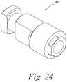
- a socket 30 on the exposed surface of a head portion 40 of an attaching bolt 50is shaped to accept a wrench (not shown) for turning the attaching bolt 50 into the threaded bore of an implant 70, as shown in FIG. 1c . It is contemplated in accordance with the present invention that each of the healing abutments described herein and shown in the figures can be secured to an implant by means of an attaching bolt, as is known in the art.
- An O-ring 60 carried on the head portion 40 of the attaching bolt 50fills an annular gap left between the head and the entrance section near the outermost (widest) opening in the entrance section.
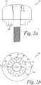
- a healing abutment 100 of FIG. 2acomprises many of the same features as the healing abutment 10 shown in FIG. 1a . Dashed lines 125 in FIG. 2b correspond to the underlying hex 125 of the healing abutment 100 in FIG. 2a .
- a top surface 129includes negative information markers (recesses) 120 that are displayed in FIG. 2a as dimples extending below the top surface 129 of the healing abutment 100.
- the top surface 129 of the healing abutment 100also possesses six notches 130 that are machined into the corners.
- the top surface 129is generally flat and merges into a rounded shape at the periphery of the healing abutment 100.
- the notches 130are used, for example, to determine the identification of the underlying implant hex position 125 or the height of the healing abutment or the diameter of the healing abutment. This embodiment is not limited to comprising six notches in the top surface 129 of the healing abutment 100. It is also contemplated that one embodiment of the present invention may possess four notches or even two notches for indicative purposes. Furthermore, it is contemplated that the information marker and notch approach could be combined or modified to provide information regarding the underlying implant seating surface diameter and implant hex angulation.
- a healing abutment 200 shown in FIGS. 3a and 3bdisplays four positive information markers 220 shown to, for example, indicate a 4 mm tall healing abutment 200. It is contemplated that the number of information markers 220 could decrease or increase depending on the height of the healing abutment 200 or another variable that the information markers have been designated to correspond.
- the positive information markers 220also define a corresponding one of the six flat surfaces of an underlying hex 225. Furthermore, dashed lines 225 in FIG. 3b correspond directly to the underlying hex 225.
- Two notches 230have also been etched or machined onto a top surface 229 of the healing abutment of FIG. 3b . These notches may indicate the diameter of the implant's seating surface.
- Lines 240are scribed on the top surface 229 of the healing abutment 200. The lines 240 are used to provide positioning or other information to the dentist or laboratory. Here, the lines 240 indicate the diameter of the healing abutment (e.g., 4 mm), hi summary, the number of the positive information markers 220 indicates the height of the healing abutment 200. The position of the positive information markers 220 indicates the orientation of the hex 225 that is the orientation of the hexagonal boss on the implant.
- the notches 230indicate the diameter of the seating surface of the implant.
- the lines 240indicate the diameter of the healing abutment 200.
- a top surface 329 of the healing abutment 300 of FIGS. 4a and 4bcomprises an etched or machined hex 335. Corners 322 of the etched hex 335 correspond directly to the position of the corners of an underlying hex 325 shown in FIG. 4a . It is contemplated in accordance with one embodiment of the present invention that further information markers may be added to the healing abutment for the dentist or laboratory to ascertain different heights or diameters.
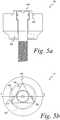
- a top surface 429 of a healing abutment 400 shown in FIGS. 5a and 5bcontains an etched or machined triangle 435. Dashed lines 425 in FIG. 5b indicate the location of an underlying hex 425. Corners 422 of the etched triangle 435 correspond to three of the six corners of the underlying hex 425. Furthermore, two negative information markers 420 are shown in FIG. 5b . As above, it is contemplated in accordance with the present invention that fewer than six information markers may exist to account for differing heights or diameters of the healing abutments.
- FIGS. 6a and 6bAnother example is shown in FIGS. 6a and 6b .
- the healing abutment 500 displayed in FIGS. 6a and 6bis a shorter version of the healing abutment 10 shown in FIGS. 1a and 1b .
- Two positive information markers 520are shown in FIG. 6b to identify the height of the healing abutment 500.
- Dashed lines 525 of the healing abutment 500correspond with the location and orientation of the underlying hex 525.
- Two notches 530are also shown in a top surface 529 of this embodiment of the present invention to show the orientation of two of the underlying flats of the underlying hex 525.
- a numeral "4" at 537is located on the top surface 529 of the healing abutment 500 to indicate, for example, the diameter of the healing abutment 500. As shown, the numeral "4" at 537 corresponds to a healing abutment 500 with a diameter of 4 mm. It is contemplated that other numerals could be placed on the top surface 529 of the healing abutment 500 to indicate other healing abutment diameters. Further, it is also contemplated that the numeral could represent the height of the healing abutment or the diameter of the underlying implant.
- an impression of the mouthis made with only the healing abutments as described herein and without the use of an impression coping.
- a model of the impressionis poured with, for example, die stone. Since the information markers are disposed on the top and/or side of the healing abutment, the laboratory has all necessary information to define the gingival aperture, the implant size and the orientation of the underlying hex. This enables the laboratory to quickly prepare the permanent components.
- the system of the present inventionalso allows the maintenance of the soft-tissue surrounding the healing abutment where in prior systems the soft tissue would close once the healing abutment was removed. The system spares the patient from the pain of removing the healing abutment.
- FIG. 8shows stereophotographic imaging, one method used for scanning. Stereophotography with a camera 703 is performed directly on the mouth cavity 705 of the patient 707. A clinician can photograph implants and other components that have been placed into or adjacent the patient's jawbone 709.
- the scanned informationis then transferred into a graphical imaging program for analysis.
- the graphical imaging software programdue to the information markers on the surface of the healing abutment, can perform a wide variety of functions.
- the graphical imaging programcan scan an opposing cast in order to develop an opposing occlusal scheme and relate this information back to the primary model. This feature is extremely important because many clinical patients have implants in both maxillary and mandibular locations.
- the graphical imaging software programis capable of generating a three-dimensional image of the emergence profile contours used on the healing abutment. If the implant is not placed in the desired esthetic location, the software program relocates the position of the restoration emergence through the soft tissue.
- the graphical imaging software programis also able to accurately relate the gingival margin for all mold, model, implant and abutment dimensions.
- the softwarecreates a transparent tooth outline for superimposition within the edentulous site.
- the occlusal outline of the "ghost" toothshould, if possible, be accurate and based on the scanned opposing occlusal dimensions. It is contemplated in accordance with the present invention that an occlusal outline is created by scanning a wax-up in order to maintain a proper plane of occlusion and healing abutment height.
- the software programsubtracts a given dimension from the mesial, distal, buccal, lingual, and occlusal areas of the superimposed tooth dimension. This allows for an even reduction of the healing abutment during fabrication to allow for proper thickness of the overlying materials (e.g., gold, porcelain, targis, etc.)-
- the graphical imaging software programalso incorporates angulation measurements into the custom abutment and subsequently calculates the dimensions of the prosthesis that are checked and modified, if necessary, by a laboratory technician. Each of the features is analyzed and determined from the different information markers that exist on the healing abutments of the present invention.
- the final dimensional information determined by the graphical imaging computer programis transferred from the computer to a milling machine (e.g., a 5-axis milling machine) to fabricate the custom abutment.
- a milling machinee.g., a 5-axis milling machine
- the custom abutmentcan be fashioned from gold or titanium or other similar metals or composites.
- a custom milled copingcan then be fabricated.
- the custom milled copingcan be formed from titanium, plastic, gold, ceramic, or other similar metals and composites.
- FIG. 7shows the exploded view of another example.
- a cap 602is placed on a healing abutment 600 and later removed during the process of taking the impression of the healing implant and surrounding features of the patient's mouth. It is contemplated in accordance with the present invention that the cap 602 could be formed from plastic or metal or a composite material. As shown in FIG. 7 , notches 604 are formed in the side(s) of the healing abutment 600. These notches correspond to notches 606 that have been preformed in the cap 602.
- the cap 602When the cap 602 is placed onto the healing abutment 600, the cap only fits snugly and properly if the number of notches 606 in the cap 602 corresponds exactly to the number of notches 604 in the side wall(s) of the healing abutment. It is contemplated in accordance with the present invention that there could be many less or more notches than is depicted in FIG. 7 . These notches correspond to information parameters such as healing abutment height, healing abutment and/or implant diameter and other parameters as listed above.
- the cap 602is securely placed over the top of the healing abutment 600.
- the impression materialis then placed over the top of the cap 602.
- the impressionis then either scanned in the patient's mouth or the impression material (with the cap 602) is then scanned and the process continues as described above.
- FIGS. 9a-9pdepict yet another example. Specifically, FIGS. 9a-9p show the top view of a plurality of healing abutments, each of which has four marking locations on the top surface of the healing abutment. For each healing abutment, a marker is either present or absent in each of the four marking locations, and the presence or absence can be interpreted either visually or by a scanning device. As explained below in detail, the markers in the marking locations permit identification of healing abutment characteristics, such as dimensions of the healing abutment.
- the four rowscorrespond to four different healing abutment heights (e.g., 3 mm, 4 mm, 6 mm, and 8 mm).
- the four columns of the coding keycorrespond to four different diameters of the healing abutment seating surfaces (e.g., 3.4 mm, 4.1 mm, 5.0 mm, and 6.0 mm). Accordingly, sixteen unique healing abutments are present.
- each of the healing abutmentshas from zero to four information markers located in the four marking locations. As shown in FIGS. 9a-9p , the marking locations extend radially from a central region of the healing abutment to the outer region of the top surface of the healing abutments (i.e., at locations of 12 o'clock, 3 o'clock, 6 o'clock, and 9 o'clock).
- a binary-coded systemexists as an array of digits, where the digits are either "1" or "0" that represent two states, respectively, ON and OFF. For each marking location, the presence of a marker ("ON") is a 1 and the absence of a marker ("OFF") is a 0.
- the determination of the sets of l's and O's derived from the information markersprovide information on the height of the healing abutment and the diameter of the seating surface of the attached implant.
- the information markers shown in FIGS. 9a-9pare in the form of grooves having rounded cross-sections.
- the present inventionprovides that the cross- section of these grooves can be rectangular, triangular, or various other shapes.
- the grooved marking locationsproduce a protruding "mound"-like element in the impression.
- This impressionis then scanned so that identifying features regarding the healing abutment can be obtained.
- a model of the patient's mouthis created from the impression such that the markings are again grooves in the model that substantially replicate the grooves in the healing abutments.
- the markerscould also be protrusions instead of grooves.
- markers not producing features in impression materialsuch as etched or laser marking, may also be used.
- FIG. 9aillustrates a top view of a healing abutment 801 that includes orientation pick-ups 802.
- These orientation pick-ups 802are also present in each of the healing abutments shown in FIGS. 9b-9p .
- the most counterclockwise of the orientation pick-ups 802i.e., the horizontal pick-up at the lower region of FIGS. 9a-9p ) is always parallel to one flat of the implant hex, as viewed from the top of the healing abutment.
- the orientation pick-ups 802are a pair of bevels on the sides of the healing abutments in FIGS. 9a-9p .
- the orientation pick-ups 802can be grooves or protruding ridges, as well.
- the orientation pick-ups 802serve a second function in that they dictate which of the four marking locations is the first marking location.
- the other three marking locationsare then read in clockwise order, proceeding from the most counterclockwise pick-up 802 to the other three marking locations on the top surface of the healing abutment.
- the information marker at 6 o'clockis the first digit in the binary code
- the information marker at 9 o'clockis the second digit in the binary code
- the information marker at 12 o'clockis the third digit in the binary code
- the information marker at 3 o'clockis the fourth digit in the binary code.
- the position of the orientation pick-ups 802allows for the determination of the position of one of the hex flats of the healing abutment (and, likewise, one of the hex flats on the implant), and also the starting point to check for the presence or absence of information markers.
- the binary code for the healing abutment 801is 0000, indicating that no grooved marker is present in any of the four predetermined positions. Since the coding key is preset (on a chart or in computer software), the binary code 0000 indicates that the healing abutment 801 is a resident of first row and first column of the matrix depicted by FIG. 9 , having a height of 3 mm and a seating surface diameter of 3.4 mm.
- the three distinct pieces of information obtained from the top of the healing abutmentallow the clinician or laboratory to know (i) the orientation of the hex of the implant, (ii) the height of the healing abutment (i.e., the location of the implant's seating surface below the healing abutment), and (iii) the seating surface diameter of the healing abutment (or the size of the implant's seating surface).
- the healing abutment 806 in FIG. 9bpossesses a binary code of 0100 because only one information marker 807 is present in the second marking location.
- the healing abutment 806is 3 mm in height and has a seating surface diameter of 4.1 mm.
- the two healing abutments 811, 816 in FIGS. 9c, 9dhave binary codes of 1000 and 1100, respectively.
- Healing abutment 811has an information marker 812 in the first marking location, while healing abutment 816 has information markers 817, 818 in the first two locations.
- the unique characteristics of these two healing abutmentsare known.
- healing abutments 821, 826, 831, 836 shown in FIGS. 9e-9h and having heights of 4 mm, but with varying seating surface diameters,would be interpreted as having binary codes 0010, 0110, 1010, and 1110, respectively.
- Healing abutment 821has one information marker 822 present in the third marking location, thus resulting in a binary code of 0010, which is indicative of a healing abutment height of 4 mm and a seating surface diameter of 3.4 mm.
- healing abutment 826 with information markers 827, 828, healing abutment 831 with information markers 832, 833, and healing abutment 836 with information markers 837, 838, 839allow determinations of the unique characteristics of these healing abutments.
- healing abutments 841, 846, 851, 856 shown in FIGS. 9i-9l and having heights of 6 mm, but with varying seating surface diameters,would be interpreted as having binary codes 0001, 0101, 1001, and 1101, respectively.
- Healing abutment 841has one information marker 842 present in the fourth marking location, thus resulting in a binary code of 0001, which is indicative of a healing abutment height of 6 mm and a seating surface diameter of 3.4 mm.
- Similar analyses on healing abutment 846 with information markers 847, 848, healing abutment 851 with information markers 852, 853, and healing abutment 856 with information markers 857, 858, 859allow determinations of the unique characteristics of these healing abutments.
- healing abutments 861, 866, 871, 876 shown in FIGS. 9m-9p and having heights of 8 mm, but with varying seating surface diameters,would be interpreted as having binary codes 0011, 0111, 1011, and 1111, respectively.
- Healing abutment 861has two information markers 862, 863, which is indicative of a healing abutment height of 8 mm and a seating surface diameter of 3.4 mm.
- Similar analyses on healing abutment 866 with information markers 867, 868, 869, healing abutment 871 with information markers 872, 873, 874, and healing abutment 876 with information markers 877, 878, 879, 880allow determinations of the unique characteristics of these healing abutments.
- the matrix of the sixteen healing abutments in FIGS. 9a-9pshow four implant seating surface diameters and four heights
- the matrixcould include other physical characteristics of the healing abutment.
- the maximum diameter of the healing abutmentcould be information obtainable through the binary-coded system.
- the type of fitting on the healing abutment and, thus, the implanti.e., internal hex or external hex
- Information unrelated to the healing abutment, but related to only the implant,could be used.
- the manufacturer of the implantcould be noted.
- information regarding the type of screw that mates with the internally thread bore of the implantcould be provided.
- FIGS. 9a-9pdemonstrate the ability of the four digit, binary-coded system to provide two physical characteristics of the healing abutment, it could provide three or more physical characteristics. For example, two seating surface sizes, four heights, and two maximum diameters would provide sixteen unique healing abutments. If more information were needed, a fifth marking location could be added to provide the opportunity for displaying thirty-two physical characteristics of the healing abutments and/or implant. And, while one marking location has been shown with marker, it is possible to have two or more markers in each marking location. For example, one circumferential groove and one radial groove within one location could represent two digits of a binary system. Alternatively, having two widths possible for each groove could provide additional indicia representative of certain information about the healing abutment.
- the set of healing abutmentscould include components shaped like the various teeth, and the information markers could provide the information regarding which tooth shape is present on the healing abutment.
- a setmay include four types of molar-shaped healing abutments, four types of bicuspid-shaped healing abutments, four types of incisor-shaped healing abutments and four types of round abutments.
- the four information marker locations on each component in the setprovide the information to determine which one of the sixteen healing abutments is being used.
- the disclosurealso includes a set of eight unique healing abutments (as opposed to the sixteen shown) requiring only three marking locations.
- the computer software and/or the visual chart in this situationwould identify these eight unique healing abutments through binary codes possessing three digits.
- the potential binary codes corresponding to an ON or OFF determination at the three marking locationsare 000, 100, 010, 001, 110, 101, 011, and 111.
- the potential binary codes in a four healing abutment matrixare 00, 10, 01, and 11.
- the orientation of the hexis known from the location of the orientation pick-ups 802 and, via the binary code, the abutment height and the seating surface of the healing abutment is known.
- Other information regarding the healing abutment and the attached implantcan also be determined by adding other markers of the type previously shown.
- the bar code 894can be located on the top surface on the healing abutment 892 such that it can be scanned or read easily.
- the bar code 894would provide the same type of information described above with respect to the information markers.
- the computer softwarewhen scanning techniques are used to learn of the information on the top of the healing abutment, the computer software is able to determine the position and orientation of the implant 900 relative to the adjacent teeth.
- the position of the implant 900is defined in a Cartesian coordinate system having "X,” “Y,” and “Z" axes.
- the common pointis at the intersection of the centerline of the implant and a plane 920 representing the seating surface 925 of the implant 900.
- the information markersassist in determining the height of the healing abutment above the implant.
- This heightcan be used to identify the zero point on the "Z" axis, which is in the plane 920 containing the seating surface 925 of the implant 900.
- the "Y" axis 910is within the plane 920 representing the seating surface 925 with the positive "Y” direction as close to the direction of facial to buccal as possible.
- the "X" axis 915is in the plane 920 and is perpendicular to an implant hex face.
- the width of the seating surface 925 in the plane 920is known, as is the width of the healing abutment emerging through the gingiva.
- the emergence profile of the artificial toothis known, as well.
- FIG. 11a perspective view of a stone cast 1000 of a mouth of a patient is shown with two stone-cast models of healing abutments 1002, 1004, which have configurations on their upper surface that correspond to the healing abutments previously described.
- the stone cast 1000is made from an impression of the mouth as previously described.
- the stone cast 1000is prepared it is scanned using a scanning technique previously described, the scanned data is transferred into a graphical imaging program, such as a Computer Aided Design ("CAD") program so that a three-dimensional (“3-D") CAD model 1100 of the stone cast 1000 is created, as shown in FIG. 12 .
- CADComputer Aided Design
- the 3-D CAD model 1100is processed such that a first altered 3-D CAD model 1200 is created, as depicted in FIG. 13 .
- the CAD program(or the operator of the CAD program) identifies the healing abutments (1002, 1004 from the stone cast 1000 of FIG. 11 ) from the cast 1000 so that the physical structure of the healing abutments may be removed from the first altered 3-D CAD model 1200.
- the first altered 3-D CAD model 1200contains the implant seating surfaces 1202, 1204 corresponding to the dental implants to which the healing abutments (1002, 1004 from the stone cast 1000 of FIG. 11 ) are attached.
- the CAD programpreferably contains the geometry of a plurality of possible implants, and models the upper surface of the implant underlying the healing abutments based on the markings contained on the healing abutments and/or information provided by the clinician.
- the CAD programfurther modifies the first altered 3-D CAD model 1200 by removing the implant seating surfaces 1202, 1204 and replacing them in a second altered 3-D CAD model 1300 with implant analog receptacles 1302, 1304 as shown in FIG. 14 .
- the CAD programcontains the geometry of a plurality of possible implant analog receptacles corresponding to the plurality of implant analogs that may be used with the system.
- Each of the implant analog receptacles 1302, 1304is adapted to receive an implant analog that is used in later steps to develop the tooth-like ceramic restoration on the custom abutment.
- the CAD programallows a rapid prototype 1400 ( FIG. 15 ) corresponding to the second altered 3-D CAD model 1300 to be created using rapid prototype equipment. It is contemplated that many rapid prototyping techniques may be utilized with the present invention such as: stereolithography, laminated-object manufacturing, selective laser sintering, solid ground curing, or other known rapid prototyping processes.
- the second altered 3-D CAD model 1300is used by the equipment controlling the rapid prototype equipment to create the rapid prototype 1400.
- the rapid prototype 1400is depicted in FIG. 15 and contains implant analogs 1402 (See FIG. 24 ), 1404 in respective implant analog receptacles 1302, 1304 of the second altered 3-D CAD model 1300.
- the implant analogs 1402, 1404may be identical, or may vary depending on the implants placed in the patient.
- the implant analogs 1402, 1404mimics the external geometry of at least a portion of an implant placed in a patient.
- the rapid prototype 1400may then be sent to a dental lab to be utilized by the dental lab, along with the custom abutment as previously described, so that a permanent, or temporary, prosthesis to fit over the custom abutment may be produced.
- Utilizing the rapid prototype 1400increases the accuracy of the prosthesis compared to using a duplicate stone cast to create the prosthesis.
- the rapid prototype 1400contains implant analogs with highly accurate placement and orientation, as human error is removed from the placement of the implant analogs in a duplicate cast stone model. Additionally, the use of the rapid prototype 1400 does not require the creation of an implant-level impression, also referred to as a surgical index. Therefore, the healing abutments in the patient's mouth do not need to be removed to create such an impression and the healing process is enhanced.
- the rapid prototype created from the second altered 3-D CAD modelwould additionally contain a rapid prototype of a custom patient- specific abutment.
- a rapid prototypewould not contain an implant analog, but instead the dental lab could simply create a permanent, or temporary, prosthesis directly from the rapid prototype without having to assemble any components to the rapid prototype. This removes yet another step where human error may occur that could adversely affect the accuracy of the prosthesis.
- a rapid prototype created from the second altered 3-D CAD modelwould contain a rapid prototype of a modified implant analog rather than an implant analog receptacle.
- the modified implant analog placed into the rapid prototypewould have a blind hole to allow a self-tapping screw to be used to secure an abutment to the rapid prototype.
- the dental labwould then be able to a permanent, or temporary, prosthesis.
- the use of the self-tapping screw and the blind holeallow eliminates the need to create threads in the rapid prototype of the implant analog, thus simplifying the rapid prototype.
- FIG. 16a stone cast 1500 is shown having implant analogs 1502, 1504 inserted into the stone cast 1500 having a soft tissue element 1506.
- the soft tissue element 1506simulates tissue in a patient's mouth.
- Soft tissue elementsare explained in greater detail in U.S. Patent Nos. RE 36,126 and RE 36,689 .
- FIG. 17shows an exploded view of the stone cast 1500 with the soft tissue element 1506 removed.
- FIG. 18depicts a 3-D CAD model 1700 of a part of the region of a stone model containing implant analog receptacles 1702, 1704 that does not contain a soft tissue element.
- the CAD programis used to modify the 3-D CAD model 1700 to create a modified 3-D CAD model with a soft tissue element 1800 containing implant analog receptacles 1802, 1804 as well as a soft tissue element 1806, as depicted in FIG. 19 .
- the modified 3-D CAD model with a soft tissue element 1800may be utilized to create a cast 1816 ( FIG. 22 ) of the soft tissue element 1806 as well as the underling stone material 1822.
- the first step in creating the cast 1816 of the soft tissue element 1806is to utilize the CAD program to generate a 3-D CAD model of a mold of the soft tissue element.
- the CAD programobtains the location of the seating surfaces of the implants, and further modifies the CAD model to locate implant analog receptacles on the CAD model. Having the proper position of the implant analogs allows the CAD program to determine the position of the soft tissue element to be used with the particular 3-D CAD model. This allows the CAD program to calculate the locations, dimensions, and volume of the soft tissue element 1806. It is contemplated that the mold used to create the cast 1816 of the soft tissue element would be a two-piece mold.
- the first mold piece 1808depicted in FIG.
- the second mold piece 1810controls the shape of the top outer surface of the cast of the soft tissue element 1816.
- the second mold piece 1810shown in FIG. 21 controls the shape of the bottom outer surface of the cast of the soft tissue element 1816.
- the second mold piece 1810contains through-hole elements 1812, 1814 to allow the cast of the soft tissue element 1816 to allow access to the implant analogs.
- the first mold piece 1808 and the second mold piece 1810may be produced using rapid prototype equipment previously described.
- the completed first mold piece 1808 and second mold piece 1810are assembled and the soft tissue material is poured into the assembled mold and the cast of the soft tissue element 1816 is created.
- FIG. 22depicts the cast of the soft tissue element 1816.
- the soft tissue element 1816has through-hole elements 1818 and 1820 so that the implant analogs in an underlying rapid prototype 1818 of a patient's mouth may be accessed.
- the soft tissue element 1816is attached to the modified rapid prototype 1822 of the patient's mouth.
- the rapid prototype 1822is created by a similar method to that previously described in relation to FIGs. 11-15 , except an area to attach the soft tissue element 1816 is created by removing a portion of the stone material from the 3-D CAD model 1700 to accommodate the soft tissue element 1816.
- a soft tissue elementmay be made directly on a rapid prototype machine.
- the previously described moldswould not be used, rather a compliant rapid prototype material would be used to form the soft tissue element directly on the rapid prototype machine.
- Computed Tomographyis used in place of the previously described scanning to generate a 3-D model of a patient's mouth.
- CTComputed Tomography
- Using the CT technologyallows the use of any abutment, removing the requirement that the abutment contain markings like those found in FIGs. 1-6 , and 9 .
- an implantis first placed within bone and allowed to osseointegrate.
- a healing abutmentis then placed on the implant.
- a CT scan of the patient's mouthis then performed, generating CT scan data.
- the CT scan datais next used in combination with medical imaging and CAD programs to generate a 3-D CAD model of a patient's mouth.
- a rapid prototype of the patient's mouthmay be generated in one of the methods previously described. Additionally, the custom abutment may be manufactured using the data obtained from the CT scan.
- the CT methodeliminates the need to take an impression of the patient's mouth and to make a stone model of the patient's mouth for creating the final, or temporary, prosthesis. The elimination of the taking the impression and making the stone model improves the accuracy of the rapid prototype of the patient's mouth by eliminating the chance to introduce error into the rapid prototype when the impression is taken or when the stone model is created.
- an intra-oral scanning techniqueis used. Instead of taking a scan of a stone model of the patient's mouth, a scan is taken within a patient's mouth that shows the patient's teeth and the healing abutment with a marking, such as those described in connection with FIGs. 1-6 , and 9.
- the data generatedis fed into the CAD program to create a 3-D CAD model of the patient's mouth.
- the rapid prototype methods described in connection with FIGs. 11-23may then be performed to create a rapid prototype model of the patient's mouth so that a permanent, or temporary, prosthesis may be formed.
- the use of intra-oral scanningeliminates the need to take an impression of the patient's mouth and make a stone model of the patient's mouth. Eliminating these steps reduces the chance to introduce error into the rapid prototype when the impression is taken or when the stone model is created.
- an ultrasonic scanmay be used to obtain ultrasonic scan data to be used to generate a 3-D CAD model of a patient's mouth.
- Using an ultrasonic technique to generate a model of a patient's mouthis disclosed in United States Patent Nos. 6,050,821 and 6,638,219 .
- a polymeric custom abutmentsuch as an acrylic custom abutment
- the acrylic custom abutmentmay be used as a temporary prosthetic abutment.
- additional componentssuch as a custom healing abutment may be manufactured utilizing a method of the present invention.
- a temporary polymeric custom abutmentmay be useful in allowing the temporary polymeric abutment to be used in a patient while a metallic custom abutment is manufactured, or to allow gingival healing or gingival sculpting.
Landscapes
- Health & Medical Sciences (AREA)
- Engineering & Computer Science (AREA)
- Materials Engineering (AREA)
- Chemical & Material Sciences (AREA)
- Epidemiology (AREA)
- Veterinary Medicine (AREA)
- Public Health (AREA)
- General Health & Medical Sciences (AREA)
- Animal Behavior & Ethology (AREA)
- Oral & Maxillofacial Surgery (AREA)
- Life Sciences & Earth Sciences (AREA)
- Dentistry (AREA)
- Physics & Mathematics (AREA)
- Manufacturing & Machinery (AREA)
- Orthopedic Medicine & Surgery (AREA)
- Optics & Photonics (AREA)
- General Physics & Mathematics (AREA)
- General Engineering & Computer Science (AREA)
- Theoretical Computer Science (AREA)
- Mechanical Engineering (AREA)
- Automation & Control Theory (AREA)
- Geometry (AREA)
- Evolutionary Computation (AREA)
- Computer Hardware Design (AREA)
- Dental Prosthetics (AREA)
- Architecture (AREA)
- Software Systems (AREA)
- Prostheses (AREA)
Description
- The present invention relates generally to a method of creating a dental laboratory model upon which a prosthetic tooth can be created.
- The dental restoration of a partially or wholly edentulous patient with artificial dentition is typically done in two stages. In the first stage, an incision is made through the gingiva to expose the underlying bone. An artificial tooth root, usually a dental implant, is placed in the jawbone for integration. The dental implant generally includes a threaded bore to receive a retaining screw holding mating components therein. During the first stage, the gum tissue overlying the implant is sutured and heals as the osseointegration process continues.
- Once the osseointegration process is complete, the second stage is initiated. Here, the gum tissue is re-opened to expose the end of the dental implant. A healing component or healing abutment is fastened to the exposed end of the dental implant to allow the gum tissue to heal therearound. Preferably, the gum tissue heals such that the aperture that remains generally approximates the size and contour of the aperture that existed around the natural tooth that is being replaced. To accomplish this, the healing abutment attached to the exposed end of the dental implant has the same general contour as the gingival portion of the natural tooth being replaced.
- During the typical second stage of dental restoration, the healing abutment is removed and an impression coping is fitted onto the exposed end of the implant. This allows an impression of the specific region of the patient's mouth to be taken so that an artificial tooth is accurately constructed. Thus, in typical dental implant systems, the healing component and the impression coping are two physically separate components. Preferably, the impression coping has the same gingival dimensions as the healing component so that there is no gap between the impression coping and the wall of the gum tissue defining the aperture. Otherwise, a less than accurate impression of the condition of the patient's mouth is made. The impression coping may be a "pick-up" type impression coping or a "transfer" type
impression coping, both known in the art. After these processes, a dental laboratory creates a prosthesis to be permanently secured to the dental implant from the impression that was made. - In addition to the method that uses the impression material and mold to manually develop a prosthesis, systems exist that utilize scanning technology to assist in generating a prosthesis. A scanning device is used in one of at least three different approaches. First, a scanning device can scan the region in the patient's mouth where the prosthesis is to be placed without the need to use impression materials or to construct a mold. Second, the impression material that is removed from the healing abutment and surrounding area is scanned. Third, a dentist or technician can scan the stone model of the dental region that was formed from the impression material and mold to produce the permanent components.
- Three basic scanning techniques exist, laser scanning, photographic imaging and mechanical sensing. Each scanning technique is used or modified for any of the above-listed approaches (a scan of the stone model, a scan of the impression material, or a scan in the mouth without using impression material) to create the prosthesis. After scanning, a laboratory can create and manufacture the permanent crown or bridge, usually using a computer aided design ("CAD") package.
- The utilization of a CAD program, as disclosed in
U.S. Pat. No. 5,338,198, (Wu ), is one method of scanning a dental region to create a three dimensional model. Preferably, after the impression is made of the patient's mouth, the impression material or stone model is placed on a support table defining the X-Y plane. A scanning laser light probe is directed onto the model. The laser light probe emits a pulse of laser light that is reflected by the model. A detector receives light scattered from the impact of the beam with the impression to calculate a Z-axis measurement. The model and the beam are relatively translated within the X-Y plane to gather a plurality of contact points with known location in the X-Y coordinate plane. The locations of several contact points in the Z-plane are determined by detecting reflected light. Finally, correlating data of the X-Y coordinates and the Z-direction contact points creates a digital image. Once a pass is complete, the model may be tilted to raise one side of the mold relative to the opposite vertically away from the X-Y plane. Subsequent to the model's second scan, the model may
be further rotated to allow for a more accurate reading of the model. After all scans are complete, the data may be fed into a CAD system for manipulation of this electronic data by known means. - Photographic imaging can also be used to scan impression material, a stone model or to scan directly in the mouth. For example, one system takes photographs at multiple angles in one exposure to scan a dental region, create a model and manufacture a prosthetic tooth. As disclosed in
U.S. Pat. No. 5,851,115, (Carlsson ), this process is generally initiated with the process of taking a stereophotograph with a camera from approximately 50 to 150 mm away from the patient's mouth. The stereophotograph can involve a photograph of a patient's mouth already prepared with implantation devices. Correct spatial positioning of the dental implants is obtained by marking the implant in several locations. The resulting photograph presents multiple images of the same object. The images on the photographs are scanned with a reading device that digitizes the photographs to produce a digital image of the dental region. The data from the scanner is electronically transmitted to a graphical imaging program that creates a model that is displayed to the user. After identification of the shape, position and other details of the model, the ultimate step is the transmission of the data to a computer for manufacturing. - A third scanning measure uses mechanical sensing. A mechanical contour sensing device, as disclosed in
U.S. Pat. No. 5,652,709 (Andersson ), is another method used to read a dental model and produce a prosthetic tooth. The impression model is secured to a table that may rotate about its longitudinal axis as well as translate along the same axis with variable speeds. A mechanical sensing unit is placed in contact with the model at a known angle and the sensing equipment is held firmly against the surface of the model by a spring. When the model is rotated and translated, the sensing equipment can measure the changes in the contour and create an electronic representation of the data. A computer then processes the electronic representation and the data from the scanning device to create a data array. The computer then compresses the data for storage and/or transmission to the milling equipment. - When the stone model of the patient's mouth is created for use in the scanning process, or in other prior techniques, a second stone model of the patient's mouth is also required to develop a final prosthesis for use in the patient. Unfortunately, accuracy
limitations on the second stone model reduce the precision of the final prosthesis. A need exists for a method that eliminates the need to create this second stone model.US2004/166463 discloses a method of creating a dental laboratory model. - A rapid prototype of a patient's dentition and dental implant analog for use in creating a patient specific prosthetic is described. The process takes an impression of a mouth including a first installation site that has a dental implant installed in the first installation site and a gingival healing abutment that has at least one informational marker attached to the dental implant. A stone model based on the impression is prepared. The stone model includes teeth models and model markers indicative of the at least one informational marker. The process scans scanning the model. Scan data are generated from the scan of the model. The scan data are transferred to a CAD program. The method creates a three-dimensional model of the installation site on the CAD program using the scan data. The process determines the at least one informational marker to gather information for manufacturing the rapid prototype of the patient's dentition. The process develops the rapid prototype dimensional information based on the three-dimensional image and the at least one informational marker. The method transfers the rapid prototype dimensional information to a rapid prototyping machine. The process fabricates the rapid prototype of the patient's dentition and dental implant analog receptacles on the rapid prototyping machine using the rapid prototype dimensional information.
- A method of manufacturing a rapid prototype of a patient's dentition and dental implant analog for use in creating a patient specific prosthesis is described. The process takes an impression of a mouth including a first installation site that has a dental implant installed in the first installation site and a gingival healing abutment having at least one informational marker attached to the dental implant. The process prepares a stone model based on the impression, the stone model includes teeth models and model markers indicative of the at least one informational marker. The method scans the model. The process generates scan data from the scan of the model. The scan data transfers to a CAD program. The process creates a three-dimensional model of the installation site on the CAD program using the scan data. The method determines the at least one informational marker to gather information for manufacturing the rapid prototype of the patient's dentition. The method develops the rapid prototype dimensional information
based on the three-dimensional image and the at least one informational marker. The process obtains soft tissue element dimensional information based on the three-dimensional image and the at least one informational marker. The method generates soft tissue element mold dimensional information based on the soft tissue element dimensional information. The method provides the soft tissue element mold dimensional information to a rapid prototyping machine. The method produces a mold of the soft tissue element on the rapid prototyping machine. The process casts the soft tissue element in the mold of the soft tissue element. The method transfers the rapid prototype dimensional information to a rapid prototyping machine. The method fabricates the rapid prototype of the patient's dentition and dental implant analog receptacles on the rapid prototyping machine using the rapid prototype dimensional information. The method assembles the soft tissue element to the rapid prototype of the patient's dentition and dental implant analog. - A method of manufacturing a custom dental prosthesis is described. The process installs a dental implant into a first installation site in bone having overlying gingiva in a mouth. The method attaches an attachment member to the dental implant. The attachment member has at least one informational marker for identifying physical characteristics of the attachment member. The process takes an impression of the mouth including the first installation site. The method prepares a stone model based on the impression. The stone model includes teeth models and model markers indicative of the at least one informational marker. The method takes an impression of the mouth including the first installation site. The process prepares a stone model based on the impression. The stone model includes teeth models and model markers indicative of the at least one informational marker. The process scans the model. The method generates scan data from the scanning of the model. The process transfers the scan data to a graphical imaging software program. The method creates a three-dimensional image of the installation site. The method determines the model markers to gather information for manufacturing the custom-abutment. The process develops custom-abutment dimensional information based on the three-dimensional image and the information gathered from the at least one informational marker. The method transfers the custom-abutment dimensional information to a milling machine. The process fabricates the custom-abutment on the milling machine utilizing the custom-abutment dimensional information. The method determines the
at least one informational marker to gather information for manufacturing a rapid prototype of the patient's mouth, including information regarding the dental implant. The process develops the rapid prototype dimensional information based on the three-dimensional image and the at least one informational marker. The method transfers the rapid prototype dimensional information to a rapid prototyping machine. The method fabricates the rapid prototype of the patient's mouth and dental implant analog receptacle on the rapid prototyping machine using the rapid prototype dimensional information. The process attaches the custom abutment to the dental implant analog on the rapid prototype of the patient's mouth and dental implant analog. The method produces a tooth-like prosthetic adapted to mate with the custom abutment. - A method to create a dental laboratory model upon which a final prosthetic tooth can be created is described. The method scans a model of a patient's mouth that has a replicated portion of a healing abutment. The method creates a CAD model from data acquired by the scan. The method uses a rapid prototype technique to create the dental laboratory model from the CAD model. The dental laboratory model includes an implant analog at a location corresponding to the replicated portion of the healing abutment.
- According to a process of the present invention, a method to create a dental laboratory model upon which a prosthetic tooth can be created is provided. The method scans a patient's mouth including a portion of a healing abutment. The method creates a CAD model from data acquired by the scan. The method uses a rapid prototype technique to create the dental laboratory model from the CAD model. The dental laboratory model includes an implant analog at a location corresponding to the portion of the healing abutment.
- A method to create a final prosthesis for an implantation site in a patient's mouth is described. The method takes an impression of the patient's mouth at the implantation site. The impression includes an impressed area corresponding to a healing abutment attached to an implant at the implantation site. The process creates a stone model from the impression. The method develops a computer model from the stone model. The method creates a custom dental abutment on the computer model. The method creates a rapid prototype model from the
computer model. The method attaches the dental abutment to the rapid prototype model. The process forms tooth-like material around the abutment. - A dental component comprises a rapid prototype model created from a CAD image of a physical model of a patient's mouth and includes an implant analog at a location substantially corresponding to a region in the patient's mouth adjacent to the dental implant.
- A dental component comprises a rapid prototype model created from a CAD image of a physical model of a patient's mouth and includes a soft tissue element at a region substantially corresponding to a region in the patient's mouth adjacent to a dental implant and further includes an implant analog at a location substantially corresponding to a region in the patient's mouth adjacent to the dental implant.
- A dental component comprises a rapid prototype model created from a CAD image of a patient's mouth and includes an implant analog at a location substantially corresponding to a region in the patient's mouth adjacent to a dental implant.
- A dental component comprises a rapid prototype model created from a CAD image of a patient's mouth and includes a soft tissue element at a region substantially corresponding to a region in the patient's mouth adjacent to a dental implant and further includes an implant analog at a location substantially corresponding to a region in the patient's mouth adjacent to the dental implant.
FIG. 1 a is a top view of a healing abutment;FIG. 1b is a longitudinal cross-sectional view of the healing abutment shown inFIG. 1a ;FIG. 1c is the healing abutment shown inFIG. 1b attached to an implant;FIG. 2a is a top view of another embodiment of a healing abutment;FIG. 2b is a longitudinal cross-sectional view of the healing abutment shown inFIG. 2a ;FIG. 3a is a top view of yet another embodiment of a healing abutment;FIG. 3b is a longitudinal cross-sectional view of the healing abutment shown inFIG. 3a ; andFIG. 4a is a top view of a further embodiment of the healing abutment;FIG. 4a is a top view of a further embodiment of the healing abutment;FIG. 4b is a longitudinal cross-sectional view of the healing abutment shown inFIG. 4a ;FIG. 5a is a top view of another embodiment of a healing abutment;FIG. 5b is a longitudinal cross-sectional view of the healing abutment shown inFIG. 5a ;FIG. 6a is a top view of another embodiment of a healing abutment;FIG. 6b is a longitudinal cross-sectional view of the healing abutment shown inFIG. 6a ;FIG. 7 is an exploded view of another embodiment of the present application;FIG. 8 is a side view of a method for stereophotographic imaging;FIGS. 9a-9p are top views of a plurality of healing abutments having a binary-type system of information markers;FIG. 9q is a top view of a healing abutment having a bar code information marker;FIG. 10 is a perspective view of a coordinate system of one embodiment of the present invention;FIG. 11 is a perspective view of a stone model of an impression of a mouth according to one embodiment of the present invention;FIG. 12 is a perspective view of a 3-D CAD model of the stone model ofFIG. 11 ;FIG. 13 is a perspective view of an altered 3-D CAD model ofFIG. 12 with the healing abutments removed from the CAD model;FIG. 14 is a perspective view of an altered 3-D CAD model ofFIG. 13 with implant analog receptacles added in the CAD model;FIG. 15 is a perspective view of a rapid prototype model of the 3-D CAD model ofFIG. 14 with implant analog receptacles;FIG. 16 is a perspective view of a stone model of an impression of a mouth with a soft tissue insert according to a further embodiment of the present invention;FIG. 17 is an exploded view of the stone model ofFIG. 16 ;FIG. 18 is a partial perspective view of a 3-D CAD model of a stone model of a mouth;FIG. 19 is a partial perspective view of an altered 3-D CAD model ofFIG. 18 with a soft tissue insert;FIG. 20 is a perspective view of a first piece of a mold of the 3-D CAD soft tissue insert ofFIG. 18 ;FIG. 21 is a perspective view of a second piece of a mold of the 3-D CAD the soft tissue insert ofFIG. 18 ;FIG. 22 is a perspective view of a soft tissue insert produce from the molds ofFIGs. 20 and 21 ;FIG. 23 is a partial perspective view of a rapid prototype model of the 3-D CAD model ofFIG. 19 ; andFIG. 24 is a perspective view of an implant analog used in conjunction with the present invention.- While the invention is susceptible to various modifications and alternative forms, specific embodiments thereof have been shown by way of example in the drawings and wall herein be described in detail. It should be understood, however, that it is not intended to limit the invention to the particular forms disclosed but, on the contrary, the intention is to cover all modifications, equivalents, and alternatives falling within the scope of the invention as defined by the appended claims.
- As shown in
FIG. 1a and 1b , thehealing abutment 10 has amain body 15 with a generally circular cross-sectional shape, a firsttapered section 17, aboundary 19, a secondtapered section 21, anend surface 23, ahex socket 25 and dimensions that are generally suitable for replicating the emergence profile of a natural tooth. The firsttapered section 17 extends downwardly from themain body 15 of theabutment 10 having a diameter at aboundary 19 that is generally larger than the implant (not shown). Theboundary 19 separates the firsttapered section 17 from the secondtapered section 21 that terminates in theend surface 23. The secondtapered section 21 is at an angle with the central axis of the implant that is generally in the range from about 5 degrees to about 15 degrees, with 10 degrees being preferable. Alternatively, the secondtapered section 21 may be omitted such that the firsttapered section 17 tapers directly to the diameter of theend surface 23 of the implant, In a further embodiment, the firsttapered section 17 may merge smoothly into the secondtapered section 21, without thedistinct boundary 19 separating the twotapered sections hex 25 is for mating with a hexagonal boss on the implant. Theend surface 23 has generally the same diameter as the seating surface of the implant. FIG. 1b discloses the top view of thesame healing abutment 10 shown inFIG. 1a . As shown inFIGS. 1a and 1b , thehealing abutment 10 haspositive information markers 20 protruding from atop surface 29 of thehealing abutment 10. Each of the sixpositive information markers 20 is disposed such that it aligns with the six corners of theunderlying hex 25. It is also contemplated in accordance with the present invention that the sixinformation markers 20 may also correspond to the height of the healing abutment. For example, two information markers might correspond to a 2 mm tall healing abutment and four information markers might correspond to a healing abutment that is 4 mm tall. In these embodiments, the two or four information markers would still be at the corners of theunderlying hex 25 so that the relative position of the hex is known.- A
socket 30 on the exposed surface of ahead portion 40 of an attachingbolt 50 is shaped to accept a wrench (not shown) for turning the attachingbolt 50 into the threaded bore of animplant 70, as shown inFIG. 1c . It is contemplated in accordance with the present invention that each of the healing abutments described herein and shown in the figures can be secured to an implant by means of an attaching bolt, as is known in the art. An O-ring 60 carried on thehead portion 40 of the attachingbolt 50 fills an annular gap left between the head and the entrance section near the outermost (widest) opening in the entrance section. - A
healing abutment 100 ofFIG. 2a comprises many of the same features as thehealing abutment 10 shown inFIG. 1a . Dashedlines 125 inFIG. 2b correspond to theunderlying hex 125 of thehealing abutment 100 inFIG. 2a . Atop surface 129 includes negative information markers (recesses) 120 that are displayed inFIG. 2a as dimples extending below thetop surface 129 of thehealing abutment 100. Thetop surface 129 of thehealing abutment 100 also possesses sixnotches 130 that are machined into the corners. Thetop surface 129 is generally flat and merges into a rounded shape at the periphery of thehealing abutment 100. - The
notches 130 are used, for example, to determine the identification of the underlyingimplant hex position 125 or the height of the healing abutment or the diameter of the healing abutment. This embodiment is not limited to comprising six notches in thetop surface 129 of thehealing abutment 100. It is also contemplated that one embodiment of the present invention may possess four notches or even two notches for indicative purposes. Furthermore, it is contemplated that the information marker and notch approach could be combined or modified to provide information regarding the underlying implant seating surface diameter and implant hex angulation. - In another example, a
healing abutment 200 shown inFIGS. 3a and 3b displays fourpositive information markers 220 shown to, for example, indicate a 4 mmtall healing abutment 200. It is contemplated that the number ofinformation markers 220 could decrease or increase depending on the height of thehealing abutment 200 or another variable that the information markers have been designated to correspond. Thepositive information markers 220 also define a corresponding one of the six flat surfaces of anunderlying hex 225. Furthermore, dashedlines 225 inFIG. 3b correspond directly to theunderlying hex 225. - Two
notches 230 have also been etched or machined onto atop surface 229 of the healing abutment ofFIG. 3b . These notches may indicate the diameter of the implant's seating surface.Lines 240 are scribed on thetop surface 229 of thehealing abutment 200. Thelines 240 are used to provide positioning or other information to the dentist or laboratory. Here, thelines 240 indicate the diameter of the healing abutment (e.g., 4 mm), hi summary, the number of thepositive information markers 220 indicates the height of thehealing abutment 200. The position of thepositive information markers 220 indicates the orientation of thehex 225 that is the orientation of the hexagonal boss on the implant. Thenotches 230 indicate the diameter of the seating surface of the implant. Thelines 240 indicate the diameter of thehealing abutment 200. - In yet another embodiment of the present invention, a
top surface 329 of thehealing abutment 300 ofFIGS. 4a and 4b comprises an etched or machinedhex 335.Corners 322 of the etchedhex 335 correspond directly to the position of the corners of anunderlying hex 325 shown inFIG. 4a . It is contemplated in accordance with one embodiment of the present invention that further information markers may be added to the healing abutment for the dentist or laboratory to ascertain different heights or diameters. - A
top surface 429 of ahealing abutment 400 shown inFIGS. 5a and 5b contains an etched or machinedtriangle 435. Dashedlines 425 inFIG. 5b indicate the location of anunderlying hex 425.Corners 422 of the etchedtriangle 435 correspond to three of the six corners of theunderlying hex 425. Furthermore, twonegative information markers 420 are shown inFIG. 5b . As above, it is contemplated in accordance with the present invention that fewer than six information markers may exist to account for differing heights or diameters of the healing abutments. - Another example is shown in
FIGS. 6a and 6b . Thehealing abutment 500 displayed inFIGS. 6a and 6b is a shorter version of thehealing abutment 10 shown inFIGS. 1a and 1b . Twopositive information markers 520 are shown inFIG. 6b to identify the height of thehealing abutment 500. Dashedlines 525 of thehealing abutment 500 correspond with the location and orientation of theunderlying hex 525. Twonotches 530 are also shown in atop surface 529 of this embodiment of the present invention to show the orientation of two of the underlying flats of theunderlying hex 525. A numeral "4" at 537 is located on thetop surface 529 of thehealing abutment 500 to indicate, for example, the diameter of thehealing abutment 500. As shown, the numeral "4" at 537 corresponds to ahealing abutment 500 with a diameter of 4 mm. It is contemplated that other numerals could be placed on thetop surface 529 of thehealing abutment 500 to indicate other healing abutment diameters. Further, it is also contemplated that the numeral could represent the height of the healing abutment or the diameter of the underlying implant. - During the second stage of the prosthetic implementation process and after a healing abutment with the information markers has been placed, an impression of the mouth is made with only the healing abutments as described herein and without the use of an impression coping. A model of the impression is poured with, for example, die stone. Since the information markers are disposed on the top and/or side of the healing abutment, the laboratory has all necessary information to define the gingival aperture, the implant size and the orientation of the underlying hex. This enables the laboratory to quickly prepare the permanent components. The system of the present invention also allows the maintenance of the soft-tissue surrounding the healing abutment where in prior systems the soft tissue would close once the healing abutment was removed. The system spares the patient from the pain of removing the healing abutment.
- To create a permanent prosthesis, the dental region is scanned, as described above, from a stone model, from the impression material, or directly in the mouth using a laser scanning technique, a photographic scanning technique or a mechanical sensing technique.
FIG. 8 shows stereophotographic imaging, one method used for scanning. Stereophotography with acamera 703 is performed directly on themouth cavity 705 of thepatient 707. A clinician can photograph implants and other components that have been placed into or adjacent the patient'sjawbone 709. - The scanned information is then transferred into a graphical imaging program for analysis. The graphical imaging software program, due to the information markers on the surface of the healing abutment, can perform a wide variety of functions. The graphical imaging program can scan an opposing cast in order to develop an opposing occlusal scheme and relate this information back to the primary model. This feature is extremely important because many clinical patients have implants in both maxillary and mandibular locations.
- The graphical imaging software program is capable of generating a three-dimensional image of the emergence profile contours used on the healing abutment. If the implant is not placed in the desired esthetic location, the software program relocates the position of the restoration emergence through the soft tissue. The graphical imaging software program is also able to accurately relate the gingival margin for all mold, model, implant and abutment dimensions. The software creates a transparent tooth outline for superimposition within the edentulous site. The occlusal outline of the "ghost" tooth should, if possible, be accurate and based on the scanned opposing occlusal dimensions. It is contemplated in accordance with the present invention that an occlusal outline is created by scanning a wax-up in order to maintain a proper plane of occlusion and healing abutment height.
- The software program subtracts a given dimension from the mesial, distal, buccal, lingual, and occlusal areas of the superimposed tooth dimension. This allows for an even reduction of the healing abutment during fabrication to allow for proper thickness of the overlying materials (e.g., gold, porcelain, targis, etc.)- The graphical imaging software program also incorporates angulation measurements into the custom abutment and subsequently calculates the dimensions of the prosthesis that are checked and modified, if necessary, by a laboratory technician. Each of the features is analyzed and determined from the different information markers that exist on the healing abutments of the present invention.
- The final dimensional information determined by the graphical imaging computer program is transferred from the computer to a milling machine (e.g., a 5-axis milling machine) to fabricate the custom abutment. It is contemplated in accordance with the present invention that the custom abutment can be fashioned from gold or titanium or other similar metals or composites. A custom milled coping can then be fabricated. It is contemplated in accordance with the present invention that the custom milled coping can be formed from titanium, plastic, gold, ceramic, or other similar metals and composites.
FIG. 7 shows the exploded view of another example. Acap 602 is placed on ahealing abutment 600 and later removed during the process of taking the impression of the healing implant and surrounding features of the patient's mouth. It is contemplated in accordance with the present invention that thecap 602 could be formed from plastic or metal or a composite material. As shown inFIG. 7 ,notches 604 are formed in the side(s) of thehealing abutment 600. These notches correspond tonotches 606 that have been preformed in thecap 602. When thecap 602 is placed onto thehealing abutment 600, the cap only fits snugly and properly if the number ofnotches 606 in thecap 602 corresponds exactly to the number ofnotches 604 in the side wall(s) of the healing abutment. It is contemplated in accordance with the present invention that there could be many less or more notches than is depicted inFIG. 7 . These notches correspond to information parameters such as healing abutment height, healing abutment and/or implant diameter and other parameters as listed above.- Specifically, after the healing abutment has been secured to the implant, the
cap 602 is securely placed over the top of thehealing abutment 600. The impression material is then placed over the top of thecap 602. The impression is then either scanned in the patient's mouth or the impression material (with the cap 602) is then scanned and the process continues as described above. FIGS. 9a-9p depict yet another example. Specifically,FIGS. 9a-9p show the top view of a plurality of healing abutments, each of which has four marking locations on the top surface of the healing abutment. For each healing abutment, a marker is either present or absent in each of the four marking locations, and the presence or absence can be interpreted either visually or by a scanning device. As explained below in detail, the markers in the marking locations permit identification of healing abutment characteristics, such as dimensions of the healing abutment.- In
FIGS. 9a-9p , the four rows correspond to four different healing abutment heights (e.g., 3 mm, 4 mm, 6 mm, and 8 mm). The four columns of the coding key correspond to four different diameters of the healing abutment seating surfaces (e.g., 3.4 mm, 4.1 mm, 5.0 mm, and 6.0 mm). Accordingly, sixteen unique healing abutments are present. - The top surface of each of the healing abutments has from zero to four information markers located in the four marking locations. As shown in
FIGS. 9a-9p , the marking locations extend radially from a central region of the healing abutment to the outer region of the top surface of the healing abutments (i.e., at locations of 12 o'clock, 3 o'clock, 6 o'clock, and 9 o'clock). - As is well known, a binary-coded system exists as an array of digits, where the digits are either "1" or "0" that represent two states, respectively, ON and OFF. For each marking location, the presence of a marker ("ON") is a 1 and the absence of a marker ("OFF") is a 0. By grouping sets of l's and O's together, information about each healing abutment is known, hi the illustrative embodiment, the determination of the sets of l's and O's derived from the information markers (e.g., via visual inspection, scanning in the mouth, scanning of the impression, or scanning of the model created by the impression) provide information on the height of the healing abutment and the diameter of the seating surface of the attached implant.
- The information markers shown in
FIGS. 9a-9p are in the form of grooves having rounded cross-sections. The present invention, however, provides that the cross- section of these grooves can be rectangular, triangular, or various other shapes. When an impression is created from the healing abutment, the grooved marking locations produce a
protruding "mound"-like element in the impression. This impression is then scanned so that identifying features regarding the healing abutment can be obtained. Alternatively, a model of the patient's mouth is created from the impression such that the markings are again grooves in the model that substantially replicate the grooves in the healing abutments. Of course, the markers could also be protrusions instead of grooves. Further, if the unique characteristics of the healing abutment are to be identified through scanning in the mouth or simply visual scanning by the clinician, then markers not producing features in impression material, such as etched or laser marking, may also be used. - Turning now to the specifics of each healing abutment,
FIG. 9a illustrates a top view of ahealing abutment 801 that includes orientation pick-ups 802. These orientation pick-ups 802 are also present in each of the healing abutments shown inFIGS. 9b-9p . The most counterclockwise of the orientation pick-ups 802 (i.e., the horizontal pick-up at the lower region ofFIGS. 9a-9p ) is always parallel to one flat of the implant hex, as viewed from the top of the healing abutment. As shown, the orientation pick-ups 802 are a pair of bevels on the sides of the healing abutments inFIGS. 9a-9p . Alternatively, the orientation pick-ups 802 can be grooves or protruding ridges, as well. - The orientation pick-
ups 802 serve a second function in that they dictate which of the four marking locations is the first marking location. The other three marking locations are then read in clockwise order, proceeding from the most counterclockwise pick-up 802 to the other three marking locations on the top surface of the healing abutment. In other words, as illustrated inFIGS. 9a-9p , the information marker at 6 o'clock is the first digit in the binary code, the information marker at 9 o'clock is the second digit in the binary code, the information marker at 12 o'clock is the third digit in the binary code, and the information marker at 3 o'clock is the fourth digit in the binary code. In summary, the position of the orientation pick-ups 802 allows for the determination of the position of one of the hex flats of the healing abutment (and, likewise, one of the hex flats on the implant), and also the starting point to check for the presence or absence of information markers. - The results of a scan (computer or visual) of the four information markers on the
healing abutment 801 produce no information markers at the four marking locations on thehealing abutment 801 ofFIG. 9a . Thus, the binary code for thehealing abutment 801 is 0000, indicating that no grooved marker is present in any of the four predetermined positions. Since the coding key is preset (on a chart or in computer software), the binary code 0000 indicates that thehealing abutment 801 is a resident of first row and first column of the matrix depicted byFIG. 9 , having a height of 3 mm and a seating surface diameter of 3.4 mm. Thus, the three distinct pieces of information obtained from the top of the healing abutment allow the clinician or laboratory to know (i) the orientation of the hex of the implant, (ii) the height of the healing abutment (i.e., the location of the implant's seating surface below the healing abutment), and (iii) the seating surface diameter of the healing abutment (or the size of the implant's seating surface). - The
healing abutment 806 inFIG. 9b possesses a binary code of 0100 because only oneinformation marker 807 is present in the second marking location. Thus, it is understood from the binary code that thehealing abutment 806 is 3 mm in height and has a seating surface diameter of 4.1 mm. The twohealing abutments FIGS. 9c, 9d have binary codes of 1000 and 1100, respectively.Healing abutment 811 has aninformation marker 812 in the first marking location, while healingabutment 816 hasinformation markers - The
healing abutments FIGS. 9e-9h and having heights of 4 mm, but with varying seating surface diameters, would be interpreted as having binary codes 0010, 0110, 1010, and 1110, respectively.Healing abutment 821 has oneinformation marker 822 present in the third marking location, thus resulting in a binary code of 0010, which is indicative of a healing abutment height of 4 mm and a seating surface diameter of 3.4 mm. Similar analyses onhealing abutment 826 withinformation markers healing abutment 831 withinformation markers healing abutment 836 withinformation markers - The
healing abutments FIGS. 9i-9l and having heights of 6 mm, but with varying seating surface diameters, would be interpreted as having binary codes 0001, 0101, 1001, and 1101, respectively.Healing abutment 841 has oneinformation marker 842 present in the fourth marking location, thus resulting in a binary code of 0001, which is indicative of a healing abutment height of 6 mm and a seating surface diameter of 3.4 mm. Similar analyses onhealing abutment 846 withinformation markers healing abutment 851 withinformation markers healing abutment 856 withinformation markers - The
healing abutments FIGS. 9m-9p and having heights of 8 mm, but with varying seating surface diameters, would be interpreted as having binary codes 0011, 0111, 1011, and 1111, respectively.Healing abutment 861 has twoinformation markers healing abutment 866 withinformation markers healing abutment 871 withinformation markers healing abutment 876 withinformation markers - While the matrix of the sixteen healing abutments in
FIGS. 9a-9p show four implant seating surface diameters and four heights, the matrix could include other physical characteristics of the healing abutment. For example, the maximum diameter of the healing abutment could be information obtainable through the binary-coded system. The type of fitting on the healing abutment and, thus, the implant (i.e., internal hex or external hex) could be provided. Information unrelated to the healing abutment, but related to only the implant, could be used. For example, the manufacturer of the implant could be noted. Or, information regarding the type of screw that mates with the internally thread bore of the implant could be provided. - Further, while
FIGS. 9a-9p demonstrate the ability of the four digit, binary-coded system to provide two physical characteristics of the healing abutment, it could provide three or more physical characteristics. For example, two seating surface sizes, four heights, and two maximum diameters would provide sixteen unique healing abutments. If more information were needed, a fifth marking location could be added to provide the opportunity for displaying thirty-two physical characteristics of the healing abutments and/or implant. And, while one marking location has been shown with marker, it is possible to have two or more markers in each marking location. For example, one circumferential groove and one radial groove within one location could represent two digits of a binary system. Alternatively, having two widths possible for each groove could provide additional indicia representative of certain information about the healing abutment. - While the invention has been described with round healing abutments, healing abutments anatomically shaped like teeth can take advantage of the information markers. Thus, the set of healing abutments could include components shaped like the various teeth, and the information markers could provide the information regarding which tooth shape is present on the healing abutment. For example, a set may include four types of molar-shaped healing abutments, four types of bicuspid-shaped healing abutments, four types of incisor-shaped healing abutments and four types of round abutments. The four information marker locations on each component in the set provide the information to determine which one of the sixteen healing abutments is being used.
- It is contemplated that the disclosure also includes a set of eight unique healing abutments (as opposed to the sixteen shown) requiring only three marking locations. The computer software and/or the visual chart in this situation would identify these eight unique healing abutments through binary codes possessing three digits. The potential binary codes corresponding to an ON or OFF determination at the three marking locations are 000, 100, 010, 001, 110, 101, 011, and 111. Similarly, if the set has only four unique healing abutments, only two marking locations would be required on the healing abutments to determine features regarding the healing abutment and the attached dental implant. The potential binary codes in a four healing abutment matrix are 00, 10, 01, and 11.
- After the top surface of a healing abutment (or the impression of the top surface, or the model of the impression of the top surface) is analyzed, the orientation of the hex is known from the location of the orientation pick-
ups 802 and, via the binary code, the abutment height and the seating surface of the healing abutment is known. Other information regarding the healing abutment and the attached implant can also be determined by adding other markers of the type previously shown. - hi addition to the markers described, it is further possible to provide a bar-coded system for providing information about the particular component, as shown in
FIG. 9q . Thebar code 894 can be located on the top surface on thehealing abutment 892 such that it can be scanned or read easily. Thus, thebar code 894 would provide the same type of information described above with respect to the information markers. - Referring to
FIG. 10 , when scanning techniques are used to learn of the information on the top of the healing abutment, the computer software is able to determine the position and orientation of theimplant 900 relative to the adjacent teeth. The position of theimplant 900 is defined in a Cartesian coordinate system having "X," "Y," and "Z" axes. The common point is at the intersection of the centerline of the implant and aplane 920 representing theseating surface 925 of theimplant 900. - As noted above, the information markers assist in determining the height of the healing abutment above the implant. This height can be used to identify the zero point on the "Z" axis, which is in the
plane 920 containing theseating surface 925 of theimplant 900. The "Y"axis 910 is within theplane 920 representing theseating surface 925 with the positive "Y" direction as close to the direction of facial to buccal as possible. The "X"axis 915 is in theplane 920 and is perpendicular to an implant hex face. Thus, the width of theseating surface 925 in theplane 920 is known, as is the width of the healing abutment emerging through the gingiva. Thus, the emergence profile of the artificial tooth is known, as well. - Turning now to
FIG. 11 , a perspective view of astone cast 1000 of a mouth of a patient is shown with two stone-cast models ofhealing abutments stone cast 1000 is made from an impression of the mouth as previously described. - Once the
stone cast 1000 is prepared it is scanned using a scanning technique previously described, the scanned data is transferred into a graphical imaging program, such as a Computer Aided Design ("CAD") program so that a three-dimensional ("3-D")CAD model 1100 of thestone cast 1000 is created, as shown inFIG. 12 . - Using the CAD program, the 3-
D CAD model 1100 is processed such that a first altered 3-D CAD model 1200 is created, as depicted inFIG. 13 . The CAD program (or the operator of the CAD program) identifies the healing abutments (1002, 1004 from the stone cast 1000 ofFIG. 11 ) from thecast 1000 so that the physical structure of the healing abutments may be removed from the first altered 3-D CAD model 1200. The first altered 3-D CAD model 1200 contains the implant seating surfaces 1202, 1204 corresponding to the dental implants to which the healing abutments (1002, 1004 from the stone cast 1000 ofFIG. 11 ) are attached. The CAD program preferably contains the geometry of a plurality of possible implants, and models the upper surface of the implant underlying the healing abutments based on the markings contained on the healing abutments and/or information provided by the clinician. - The CAD program further modifies the first altered 3-
D CAD model 1200 by removing the implant seating surfaces 1202, 1204 and replacing them in a second altered 3-D CAD model 1300 withimplant analog receptacles FIG. 14 . The CAD program contains the geometry of a plurality of possible implant analog receptacles corresponding to the plurality of implant analogs that may be used with the system. Each of theimplant analog receptacles - Once the second altered 3-
D CAD model 1300 is created, the CAD program allows a rapid prototype 1400 (FIG. 15 ) corresponding to the second altered 3-D CAD model 1300 to be created using rapid prototype equipment. It is contemplated that many rapid prototyping techniques may be utilized with the present invention such as: stereolithography, laminated-object manufacturing, selective laser sintering, solid ground curing, or other known rapid prototyping processes. The second altered 3-D CAD model 1300 is used by the equipment controlling the rapid prototype equipment to create therapid prototype 1400. - The
rapid prototype 1400 is depicted inFIG. 15 and contains implant analogs 1402 (SeeFIG. 24 ), 1404 in respectiveimplant analog receptacles D CAD model 1300. Theimplant analogs implant analogs rapid prototype 1400 may then be sent to a dental lab to be utilized by the dental lab, along with the custom abutment as previously described, so that a permanent, or temporary, prosthesis to fit over the custom abutment may be produced. Utilizing therapid prototype 1400 increases the accuracy of the prosthesis compared to using a duplicate stone cast to create the prosthesis. Therapid prototype 1400 contains implant analogs with highly accurate placement and orientation, as human error is removed from the placement of the implant analogs in a duplicate cast stone model. Additionally, the use of therapid prototype 1400 does not require the creation of an implant-level impression, also referred to as a surgical index. Therefore, the healing abutments in the patient's mouth do not need to be removed to create such an impression and the healing process is enhanced. - It is further contemplated that the rapid prototype created from the second altered 3-D CAD model would additionally contain a rapid prototype of a custom patient- specific abutment. Such a rapid prototype would not contain an implant analog, but instead the dental lab could simply create a permanent, or temporary, prosthesis directly from the rapid prototype without having to assemble any components to the rapid prototype. This removes yet another step where human error may occur that could adversely affect the accuracy of the prosthesis.
- Additionally, it is contemplated that a rapid prototype created from the second altered 3-D CAD model would contain a rapid prototype of a modified implant analog rather than an implant analog receptacle. The modified implant analog placed into the rapid prototype would have a blind hole to allow a self-tapping screw to be used to secure an abutment to the rapid prototype. The dental lab would then be able to a permanent, or temporary, prosthesis. The use of the self-tapping screw and the blind hole allow eliminates the need to create threads in the rapid prototype of the implant analog, thus simplifying the rapid prototype.
- Turning now to
FIG. 16 , astone cast 1500 is shown havingimplant analogs stone cast 1500 having asoft tissue element 1506. Thesoft tissue element 1506 simulates tissue in a patient's mouth. Soft tissue elements are explained in greater detail inU.S. Patent Nos. RE 36,126 andRE 36,689 .FIG. 17 shows an exploded view of thestone cast 1500 with thesoft tissue element 1506 removed. - In order to create a stone model of a patient's mouth having both a soft tissue element and a more traditional dental stone material section, more than one material must be used when forming the model of the patient's mouth. Thus, the portion of the stone model around the dental implant will contain soft tissue model material, such as silicone, and the rest of the stone model contains traditional stone die material. The soft tissue model is typically removable from the rest of the stone model.
FIG. 18 depicts a 3-D CAD model 1700 of a part of the region of a stone model containingimplant analog receptacles CAD model 1700 to create a modified 3-D CAD model with asoft tissue element 1800 containingimplant analog receptacles soft tissue element 1806, as depicted inFIG. 19 . The modified 3-D CAD model with asoft tissue element 1800 may be utilized to create a cast 1816 (FIG. 22 ) of thesoft tissue element 1806 as well as theunderling stone material 1822. - The first step in creating the
cast 1816 of thesoft tissue element 1806 is to utilize the CAD program to generate a 3-D CAD model of a mold of the soft tissue element. As previously described, the CAD program obtains the location of the seating surfaces of the implants, and further modifies the CAD model to locate implant analog receptacles on the CAD model. Having the proper position of the implant analogs allows the CAD program to determine the position of the soft tissue element to be used with the particular 3-D CAD model. This allows the CAD program to calculate the locations, dimensions, and volume of thesoft tissue element 1806. It is contemplated that the mold used to create thecast 1816 of the soft tissue element would be a two-piece mold. Thefirst mold piece 1808, depicted inFIG. 20 , controls the shape of the top outer surface of the cast of thesoft tissue element 1816. Thesecond mold piece 1810, shown inFIG. 21 controls the shape of the bottom outer surface of the cast of thesoft tissue element 1816. Thesecond mold piece 1810 contains through-hole elements soft tissue element 1816 to allow access to the implant analogs. Thefirst mold piece 1808 and thesecond mold piece 1810 may be produced using rapid prototype equipment previously described. The completedfirst mold piece 1808 andsecond mold piece 1810 are assembled and the soft tissue material is poured into the assembled mold and the cast of thesoft tissue element 1816 is created.FIG. 22 depicts the cast of thesoft tissue element 1816. Thesoft tissue element 1816 has through-hole elements rapid prototype 1818 of a patient's mouth may be accessed. Thesoft tissue element 1816 is attached to the modifiedrapid prototype 1822 of the patient's mouth. Therapid prototype 1822 is created by a similar method to that previously described in relation toFIGs. 11-15 , except an area to attach thesoft tissue element 1816 is created by removing a portion of the stone material from the 3-D CAD model 1700 to accommodate thesoft tissue element 1816. - According to an alternate embodiment of the present invention, a soft tissue element may be made directly on a rapid prototype machine. In such an embodiment the previously described molds would not be used, rather a compliant rapid prototype material would be used to form the soft tissue element directly on the rapid prototype machine.
- According to an alternate embodiment of the present invention, Computed Tomography ("CT") technology is used in place of the previously described scanning to generate a 3-D model of a patient's mouth. Using the CT technology allows the use of any abutment, removing the requirement that the abutment contain markings like those found in
FIGs. 1-6 , and9 . To use the CT method, an implant is first placed within bone and allowed to osseointegrate. A healing abutment is then placed on the implant. A CT scan of the patient's mouth is then performed, generating CT scan data. The CT scan data is next used in combination with medical imaging and CAD programs to generate a 3-D CAD model of a patient's mouth. Once the 3-D CAD model of the patient's mouth is created, a rapid prototype of the patient's mouth may be generated in one of the methods previously described. Additionally, the custom abutment may be manufactured using the data obtained from the CT scan. The CT method eliminates the need to take an impression of the patient's mouth and to make a stone model of the patient's mouth for creating the final, or temporary, prosthesis. The elimination of the taking the impression and making the stone model improves the accuracy of the rapid prototype of the patient's mouth by eliminating the chance to introduce error into the rapid prototype when the impression is taken or when the stone model is created. - According to another alternate embodiment of the present invention, an intra-oral scanning technique is used. Instead of taking a scan of a stone model of the patient's mouth, a scan is taken within a patient's mouth that shows the patient's teeth and the healing abutment with a marking, such as those described in connection with
FIGs. 1-6 , and 9. Once the intra-oral scan is complete, the data generated is fed into the CAD program to create a 3-D CAD model of the patient's mouth. The rapid prototype methods described in connection withFIGs. 11-23 may then be performed to create a rapid prototype model of the patient's mouth so that a permanent, or temporary, prosthesis may be formed. The use of intra-oral scanning eliminates the need to take an impression of the patient's mouth and make a stone model of the patient's mouth. Eliminating these steps reduces the chance to introduce error into the rapid prototype when the impression is taken or when the stone model is created. - In addition to CT scanning, it is possible that an ultrasonic scan may be used to obtain ultrasonic scan data to be used to generate a 3-D CAD model of a patient's mouth. Using an ultrasonic technique to generate a model of a patient's mouth is disclosed in United States Patent Nos.
6,050,821 and6,638,219 . - In addition to milling a custom abutment from a metallic material, utilizing a process of the present invention, it is further contemplated that a polymeric custom abutment, such as an acrylic custom abutment, may be made from a 3-D CAD model. The acrylic custom abutment may be used as a temporary prosthetic abutment. It is additionally contemplated that additional components, such as a custom healing abutment may be manufactured utilizing a method of the present invention. A temporary polymeric custom abutment may be useful in allowing the temporary polymeric abutment to be used in a patient while a metallic custom abutment is manufactured, or to allow gingival healing or gingival sculpting.
- While particular embodiments and applications of the present invention have been illustrated and described, it is to be understood that the invention is not limited to the precise construction and compositions disclosed herein and that various modifications, changes, and variations may be apparent from the foregoing descriptions without departing from the scope of the invention as defined in the appended claims.
Claims (17)
- A method of creating a dental laboratory model upon which a prosthetic tooth can be created comprising:scanning a patient's mouth including a portion of a healing abutment (10,100,200,300,400,500,600) ;creating a CAD model (1100) from data acquired by the scanning;using a rapid prototype technique to create the dental laboratory model from the CAD model (1100), the dental laboratory model including an implant analog (1402,1404) at a location corresponding to the portion of the healing abutment.
- The method according to claim 1, wherein the scanning is a laser scanning technique.
- The method according to claim 1, wherein the scanning is a mechanical sensing technique.
- The method according to claim 1, wherein the scanning is a photographic scanning technique.
- The method according to claim 4, wherein the photographic scanning technique is a stereophotographic imaging technique.
- The method according to claims 1 to 4, wherein the rapid prototype technique is a stereolithographic rapid prototype technique.
- The method according to claims 1 to 4, wherein the rapid prototype technique is a laminate object manufacturing rapid prototype technique.
- The method according to claims 1 to 4, wherein the rapid prototype technique is a selective laser sintering rapid prototype technique.
- The method according to claim 1, wherein the 3-D CAD model is processed to create a first (1200) and a second (1300) altered 3-D CAD model which then allows a rapid prototype of a modified implant analog to be created using the rapid prototyping technique, the modified implant analog having a blind hole.
- The method according to claim 1, wherein the healing abutment includes at least one informational marker (20,120,220,420,520).
- The method according to claim 10, wherein the at least one informational marker provides information regarding an underlying dental implant.
- The method according to claim 11, wherein the information from the at least one informational marker is used for creating the dental laboratory model.
- The method according to claims 9 to 12, further comprising adding a compliant soft tissue element (1506,1806,1816) to the dental laboratory model in a region adjacent to the implant analog.
- The method according to claim 13, wherein the compliant soft tissue element is made by the rapid prototyping technique.
- The method according to claim 14, wherein the material comprising the compliant soft tissue element is different than a base material of the rapid-prototyped dental laboratory model.
- The method according to claim 13, wherein the compliant soft tissue element surrounds the implant analog and includes an implant analog receptacle (1802,1804) leading to the implant analog.
- The method according to claim 16, wherein the implant analog is inserted into the implant analog receptacle in the rapid-prototyped dental laboratory model.
Priority Applications (2)
| Application Number | Priority Date | Filing Date | Title |
|---|---|---|---|
| EP15161961.6AEP2921131B1 (en) | 2005-06-30 | 2006-06-29 | Method for manufacturing dental implant components |
| DE06785810.0TDE06785810T1 (en) | 2005-06-30 | 2006-06-29 | METHOD FOR PRODUCING COMPONENTS OF A DENTAL IMPLANT |
Applications Claiming Priority (2)
| Application Number | Priority Date | Filing Date | Title |
|---|---|---|---|
| US69550105P | 2005-06-30 | 2005-06-30 | |
| PCT/US2006/025292WO2007005490A2 (en) | 2005-06-30 | 2006-06-29 | Method for manufacturing dental implant components |
Related Child Applications (2)
| Application Number | Title | Priority Date | Filing Date |
|---|---|---|---|
| EP15161961.6ADivision-IntoEP2921131B1 (en) | 2005-06-30 | 2006-06-29 | Method for manufacturing dental implant components |
| EP15161961.6ADivisionEP2921131B1 (en) | 2005-06-30 | 2006-06-29 | Method for manufacturing dental implant components |
Publications (3)
| Publication Number | Publication Date |
|---|---|
| EP1906862A2 EP1906862A2 (en) | 2008-04-09 |
| EP1906862A4 EP1906862A4 (en) | 2013-07-31 |
| EP1906862B1true EP1906862B1 (en) | 2018-05-23 |
Family
ID=37604994
Family Applications (2)
| Application Number | Title | Priority Date | Filing Date |
|---|---|---|---|
| EP06785810.0ANot-in-forceEP1906862B1 (en) | 2005-06-30 | 2006-06-29 | Method of creating a dental laboratory model |
| EP15161961.6AActiveEP2921131B1 (en) | 2005-06-30 | 2006-06-29 | Method for manufacturing dental implant components |
Family Applications After (1)
| Application Number | Title | Priority Date | Filing Date |
|---|---|---|---|
| EP15161961.6AActiveEP2921131B1 (en) | 2005-06-30 | 2006-06-29 | Method for manufacturing dental implant components |
Country Status (6)
| Country | Link |
|---|---|
| US (9) | US8185224B2 (en) |
| EP (2) | EP1906862B1 (en) |
| DE (2) | DE06785810T1 (en) |
| ES (1) | ES2845610T3 (en) |
| SI (1) | SI2921131T1 (en) |
| WO (1) | WO2007005490A2 (en) |
Families Citing this family (71)
| Publication number | Priority date | Publication date | Assignee | Title |
|---|---|---|---|---|
| JPH0249958A (en)* | 1988-08-11 | 1990-02-20 | Kubota Ltd | Direct injection diesel engine piston |
| US6790040B2 (en)* | 1999-11-10 | 2004-09-14 | Implant Innovations, Inc. | Healing components for use in taking impressions and methods for making the same |
| DE06785810T1 (en) | 2005-06-30 | 2016-03-10 | Biomet 3I, Llc | METHOD FOR PRODUCING COMPONENTS OF A DENTAL IMPLANT |
| US8257083B2 (en) | 2005-10-24 | 2012-09-04 | Biomet 3I, Llc | Methods for placing an implant analog in a physical model of the patient's mouth |
| US11219511B2 (en) | 2005-10-24 | 2022-01-11 | Biomet 3I, Llc | Methods for placing an implant analog in a physical model of the patient's mouth |
| DE102007014985A1 (en)* | 2007-03-28 | 2008-10-02 | Aepsilon Rechteverwaltungs Gmbh | Method of making dental prostheses, method of creating a dataset and computer readable medium |
| RU2369354C2 (en)* | 2007-12-07 | 2009-10-10 | Алексей Юрьевич Ремов | Method of creating medical template based on information about digital representation of body part |
| US8509932B2 (en)* | 2008-07-17 | 2013-08-13 | Cadent Ltd. | Methods, systems and accessories useful for procedures relating to dental implants |
| EP2181664A1 (en)* | 2008-10-31 | 2010-05-05 | DeguDent GmbH | Method for manufacturing a functional dental prosthesis |
| ITSV20100004A1 (en)* | 2010-06-07 | 2011-12-08 | Piero Siccardi | DEVIM (DENTAL VIRTUAL INTEGRATED MODELING) DENTAL INTEGRATED VIRTUAL MODELING PROCEDURE |
| EP3725260B1 (en) | 2011-01-13 | 2023-06-07 | Align Technology, Inc. | Method and system for creating a virtual dental model |
| ES2364393B1 (en)* | 2011-02-21 | 2012-08-03 | Josep Soler Cegarra | METHOD FOR THE DESIGN OF DENTAL PROSTHETIC STRUCTURES ON IMPLANTS. |
| EP3388022B1 (en)* | 2011-02-23 | 2020-01-29 | 3Shape A/S | Method of modifying the gingival part of a virtual model of a set of teeth |
| US8944816B2 (en) | 2011-05-16 | 2015-02-03 | Biomet 3I, Llc | Temporary abutment with combination of scanning features and provisionalization features |
| DE102011115031A1 (en)* | 2011-10-07 | 2013-04-11 | Heraeus Kulzer Gmbh | Laboratory implant with indexing for insertion in plastic models |
| ES2371897B1 (en)* | 2011-10-14 | 2013-01-24 | Phibo Dental Solutions, S.L. | DENTAL MODELS AND DENTAL MODELS MANUFACTURING PROCEDURE. |
| US10610299B2 (en)* | 2011-12-14 | 2020-04-07 | Stryker European Holdings I, Llc | Technique for generating a bone plate design |
| US9089382B2 (en) | 2012-01-23 | 2015-07-28 | Biomet 3I, Llc | Method and apparatus for recording spatial gingival soft tissue relationship to implant placement within alveolar bone for immediate-implant placement |
| US9452032B2 (en) | 2012-01-23 | 2016-09-27 | Biomet 3I, Llc | Soft tissue preservation temporary (shell) immediate-implant abutment with biological active surface |
| US8425231B1 (en) | 2012-01-23 | 2013-04-23 | Mark N. Hochman | Soft-tissue preservation temporary (shell) immediate-implant abutment method and device |
| US9198627B2 (en) | 2012-04-16 | 2015-12-01 | Biomet 3i | System and method for improved intra-oral scanning protocol and calibration |
| EP2676630A1 (en)* | 2012-06-23 | 2013-12-25 | Robert Böttcher | Scan post for determining the exact position of an implant tooth to be produced |
| GB201212125D0 (en) | 2012-07-09 | 2012-08-22 | Nobel Biocare Services Ag | Abutment system and dental methods |
| US20140080092A1 (en)* | 2012-09-14 | 2014-03-20 | Biomet 3I, Llc | Temporary dental prosthesis for use in developing final dental prosthesis |
| US9554880B2 (en)* | 2012-10-25 | 2017-01-31 | Zfx Gmbh | Reference member for determining a position of an implant analog |
| WO2014081843A1 (en) | 2012-11-20 | 2014-05-30 | Advanced Implant Intellectual Properties, Llc | Universal aligning adaptor system and methods |
| US8905757B2 (en) | 2012-12-03 | 2014-12-09 | E. Kats Enterprises Ltd. | Method and apparatus for measuring a location and orientation of a plurality of implants |
| US8926328B2 (en) | 2012-12-27 | 2015-01-06 | Biomet 3I, Llc | Jigs for placing dental implant analogs in models and methods of doing the same |
| SE1350114A1 (en)* | 2013-01-31 | 2014-08-01 | Heraeus Dental Ab | Method of manufacturing a dental superstructure |
| US9839496B2 (en) | 2013-02-19 | 2017-12-12 | Biomet 3I, Llc | Patient-specific dental prosthesis and gingival contouring developed by predictive modeling |
| DE102014102997B4 (en) | 2013-03-08 | 2022-03-24 | Gottinger Handelshaus Ohg | Method for static transfer of a test orthopedic device to a definitive orthopedic device |
| DE102013004175B4 (en)* | 2013-03-12 | 2017-01-26 | Bruno Spindler | Implant analog and analog bearing body |
| US9687327B2 (en) | 2013-03-14 | 2017-06-27 | Anthony Prestipino | Apparatuses and methods for making a final hybrid prosthesis to be attached to dental implants |
| US9655697B2 (en)* | 2013-03-14 | 2017-05-23 | William M. Aerni | Universal digital dental implant scanning code and method |
| US9801699B2 (en) | 2013-03-14 | 2017-10-31 | Devin Okay | Paired templates for placing dental implants and enhancing registration for denture prosthetics attached to the implants |
| ES2910276T3 (en)* | 2013-04-09 | 2022-05-12 | Biomet 3I Llc | Method of using scan data of a dental implant |
| US20140343706A1 (en)* | 2013-05-14 | 2014-11-20 | Timothy O. Hart | Customizable Healing Abutment |
| GB2519296A (en) | 2013-10-15 | 2015-04-22 | Nobel Biocare Services Ag | Dental implant replica |
| EP3998040B1 (en) | 2013-12-20 | 2025-09-03 | Biomet 3i, LLC | Dental method for developing custom prostheses through scanning of coded members |
| EP3134025A4 (en) | 2014-04-22 | 2018-01-10 | T.A.G. Medical Devices - Agriculture Cooperative Ltd. | Dental implants |
| WO2015168022A1 (en) | 2014-04-27 | 2015-11-05 | The Research Foundation For The State University Of New York | Enamel products and methods of use |
| US10016262B2 (en)* | 2014-06-16 | 2018-07-10 | Align Technology, Inc. | Unitary dental model |
| US9700390B2 (en) | 2014-08-22 | 2017-07-11 | Biomet 3I, Llc | Soft-tissue preservation arrangement and method |
| US10639132B2 (en)* | 2014-09-12 | 2020-05-05 | Italo Lozada | Dental prosthesis |
| DE202015000801U1 (en)* | 2015-01-26 | 2015-02-25 | Nt-Trading Gmbh & Co. Kg | Scanbörpersystem for determining a positioning and alignment of a dental implant |
| ES2675036T3 (en) | 2015-03-09 | 2018-07-05 | Medentika Gmbh | Laboratory replica for insertion into a cavity of a print model |
| EP3267936A4 (en) | 2015-03-09 | 2018-12-26 | Stephen J. Chu | Gingival ovate pontic and methods of using the same |
| GB201505400D0 (en)* | 2015-03-30 | 2015-05-13 | Rolls Royce Plc | Multi coordinate reference system for positioning bladed drum |
| ITUB20154970A1 (en)* | 2015-10-20 | 2017-04-20 | Easy Driver Group S R L S | METHOD FOR POSITIONING THE ANALOGUE REFERENCES IN THE CONSTRUCTION OF ORTHODONTIC EQUIPMENT WITH MINI SKELETON ANCHORAGE SCREWS |
| CN108135676B (en) | 2015-11-20 | 2021-08-06 | 诺贝尔生物服务公司 | Healing cap with scannable features |
| WO2017173333A2 (en) | 2016-03-31 | 2017-10-05 | Lee Ernesto A | Method, devices and articles for conducting subperiosteal minimally invasive aesthetic jaw bone grafting augmentation |
| GR1009203B (en)* | 2016-08-08 | 2018-01-23 | Φοιβος Κυριακου Ψαρομματης-Γιαννακοπουλος | Methodology and arrangement for the production of individualized dental implants in the intervention place |
| US10905528B2 (en)* | 2016-09-21 | 2021-02-02 | Global Dental Science, LLC | System and method for registering implant orientation directly from a dental impression |
| US10052180B1 (en) | 2016-12-29 | 2018-08-21 | David D. Richter | Virtual dental articulator and system |
| USD950059S1 (en) | 2017-03-31 | 2022-04-26 | Ernesto A. Lee | Subperiosteal surgical instrument |
| US20180353267A1 (en) | 2017-06-13 | 2018-12-13 | Biomet 3I, Llc | Combination impression coping and scan body |
| US11273020B2 (en)* | 2017-06-13 | 2022-03-15 | Biomet 3I, Llc | Implant analogs and methods |
| US12274599B2 (en) | 2017-08-16 | 2025-04-15 | Global Dental Science, LLC | Bar manufacturing and denture reference and registration system |
| FR3074030B1 (en) | 2017-11-24 | 2019-10-25 | Euroteknika | METHOD FOR MANUFACTURING A DENTAL RESTORATIVE ASSEMBLY |
| CN108247055B (en)* | 2018-02-12 | 2019-01-29 | 成都优材科技有限公司 | The digitlization integrated molding method of dentistry attachment |
| GB201802402D0 (en)* | 2018-02-14 | 2018-03-28 | Littlejohn Alexander | Apparatus and method for prosthodontics |
| US11986363B2 (en) | 2018-02-16 | 2024-05-21 | Global Dental Science, LLC | Real time anatomical adaptation |
| KR102250959B1 (en)* | 2018-11-30 | 2021-05-12 | (주) 예스바이오테크 | Customized abutment for fixing crown |
| US12038803B2 (en) | 2019-03-29 | 2024-07-16 | Biomet 3I, Llc | Optimized library solution for dental implants |
| US10849723B1 (en) | 2019-05-07 | 2020-12-01 | Sdc U.S. Smilepay Spv | Scanning device |
| EP4054470A4 (en)* | 2019-11-04 | 2023-11-15 | Implant Solutions Pty Ltd | Apparatus for facilitating acquisition of a scan and an intraoral scanning procedure |
| RU2769621C2 (en)* | 2020-08-31 | 2022-04-04 | Общество с ограниченной ответственностью "Инновационно-Технологическая Компания Эндопринт" (ООО"Инновационно-Технологическая Компания Эндопринт") | Guiding template for dental surgery |
| CN112451136B (en)* | 2020-11-13 | 2022-02-18 | 北京联袂义齿技术有限公司 | Preparation method of 3D printed dental implant |
| US20230119403A1 (en) | 2021-10-20 | 2023-04-20 | Biomet 3I, Llc | Angulated screw channel for dental implant |
| IT202100027989A1 (en) | 2021-11-03 | 2023-05-03 | Diego Crovato | APPARATUS AND METHOD FOR ACQUIRING A DENTAL IMPRESSION BY MEANS OF INTRAORAL DIGITAL SCAN |
| CN118097034B (en)* | 2024-04-24 | 2024-07-09 | 先临三维科技股份有限公司 | Method, device, equipment and medium for processing data of implant |
Citations (1)
| Publication number | Priority date | Publication date | Assignee | Title |
|---|---|---|---|---|
| US20040166463A1 (en)* | 2003-02-26 | 2004-08-26 | Align Technology, Inc. | Systems and methods for combination treatments of dental patients |
Family Cites Families (459)
| Publication number | Priority date | Publication date | Assignee | Title |
|---|---|---|---|---|
| US3958471A (en) | 1972-02-08 | 1976-05-25 | Paul-Heinz Wagner Maschinenfabrikation | Method of and apparatus for manufacturing workpieces having polygonyl inner and outer contours |
| US3919772A (en) | 1973-06-04 | 1975-11-18 | Joseph J Lenczycki | Dental implant assembly and method for attaching the same to the jaw bone |
| US3906634A (en) | 1974-12-19 | 1975-09-23 | Thomas E Aspel | Method of marking archwire with tooth width measurements |
| US4086701A (en) | 1975-04-07 | 1978-05-02 | Kyoto Ceramic Kabushiki Kaisha | Device for implanting an artificial endosseous element of ceramics and an implant method for use of the same |
| US4011602A (en)* | 1975-10-06 | 1977-03-15 | Battelle Memorial Institute | Porous expandable device for attachment to bone tissue |
| US4056585A (en) | 1976-05-20 | 1977-11-01 | Waltke Robert W | Tooth die and method and apparatus for making the same |
| US4177562A (en) | 1977-05-02 | 1979-12-11 | Miller Alvin L | Dental implant and method of inserting the same |
| US4199102A (en)* | 1978-07-05 | 1980-04-22 | Dunham-Bush, Inc. | Temperature control system |
| US4325373A (en)* | 1978-08-01 | 1982-04-20 | Carbo Mediec Inc. | Apparatus for forming an osteotomy for a dental implant |
| CH640719A5 (en) | 1979-04-30 | 1984-01-31 | Schoeler Arno | DEVICE FOR STORING SMALL MEDICAL INSTRUMENTS. |
| US4294544A (en) | 1979-08-03 | 1981-10-13 | Altschuler Bruce R | Topographic comparator |
| US4364381A (en) | 1980-01-31 | 1982-12-21 | Sher Jay H | Surgical clamp and drill-guiding instrument |
| US4306862A (en) | 1980-08-18 | 1981-12-22 | Knox Kathleen K | Dental burr tool block assembly |
| US4624673A (en) | 1982-01-21 | 1986-11-25 | United States Medical Corporation | Device system for dental prosthesis fixation to bone |
| US4439152A (en)* | 1982-03-04 | 1984-03-27 | Small Irwin A | Method of jawbone abutment implant for dental prostheses and implant device |
| FR2525103B1 (en) | 1982-04-14 | 1985-09-27 | Duret Francois | IMPRESSION TAKING DEVICE BY OPTICAL MEANS, PARTICULARLY FOR THE AUTOMATIC PRODUCTION OF PROSTHESES |
| US4663720A (en) | 1984-02-21 | 1987-05-05 | Francois Duret | Method of and apparatus for making a prosthesis, especially a dental prosthesis |
| US4547157A (en) | 1983-04-20 | 1985-10-15 | Miter, Inc. | Submergible post-type dental implant system and method of using same |
| US4543953A (en) | 1983-07-18 | 1985-10-01 | Cordis Corporation | Analog telemetry system for biomedical implant |
| SE446370B (en) | 1983-11-25 | 1986-09-08 | Astra Meditec Ab | IMPLANT FOR FIXING DENTAL PROTEINS |
| US4571180A (en)* | 1984-03-08 | 1986-02-18 | Kulick Walter K | Dental instrument |
| SE450334B (en) | 1985-09-16 | 1987-06-22 | Dan Lundgren | CONNECTOR TO ORAL PROTESTS INCLUDING A HEAT-SHAPED MATRIX |
| SE469321B (en)* | 1986-04-14 | 1993-06-21 | Joenkoepings Laens Landsting | SET AND DEVICE TO MAKE A MODIFIED THREE-DIMENSIONAL IMAGE OF AN ELASTIC DEFORMABLE PURPOSE |
| US5344457A (en) | 1986-05-19 | 1994-09-06 | The University Of Toronto Innovations Foundation | Porous surfaced implant |
| US5071351A (en) | 1986-07-02 | 1991-12-10 | Collagen Corporation | Dental implant system |
| US4713004A (en) | 1986-09-04 | 1987-12-15 | Vent Plant Corporation | Submergible screw-type dental implant and method of utilization |
| US4842518A (en) | 1986-09-04 | 1989-06-27 | Vent-Plant Corporation | Submergible screw-type dental implant and method of utilization |
| US4758161A (en) | 1987-01-28 | 1988-07-19 | Core-Vent Corporation | Coping insert for use with a dental implant |
| SE457691B (en)* | 1987-05-22 | 1989-01-23 | Nobel Plast Ab | METHOD FOR PREPARING PROTETIC CONSTRUCTIONS OF COMPOSITION MATERIAL WITH SIGNIFICANT FIBER CONTENT |
| US4767331A (en) | 1987-05-28 | 1988-08-30 | Hoe Khin A | Dental crown manufacturing apparatus |
| SE457769B (en)* | 1987-06-12 | 1989-01-30 | Nobelpharma Ab | DISTANCE ORGANIZATION FOR DENTAL IMPLANT |
| US5087200B1 (en)* | 1987-06-12 | 1996-05-07 | Nobelpharma Ab | Spacer for dental implants |
| SE458499B (en)* | 1987-06-25 | 1989-04-10 | Astra Meditec Ab | SET AND DEVICE FOR PREPARING A DENTAL BRIDGE |
| DE3723555C2 (en) | 1987-07-16 | 1994-08-11 | Steinbichler Hans | Process for the production of dentures |
| US5015186A (en) | 1987-09-24 | 1991-05-14 | Detsch Steven G | Dental implant attachment system |
| US4854872B1 (en) | 1987-09-24 | 1995-06-27 | Steven G Detsch | Prosthetic implant attachment system and method |
| US4850870C1 (en) | 1987-10-23 | 2001-07-24 | Implant Innovations Inc | Prosthodontic restoration components |
| US4856994A (en) | 1988-01-25 | 1989-08-15 | Implant Innovations, Inc. | Periodontal restoration components |
| DE3802789A1 (en)* | 1988-01-29 | 1989-08-10 | Lauks Nikola | DRILLING DEVICE FOR ORGANIC SURGICAL IMPLANT CAVITIES AND METHOD FOR PRODUCING A DRILL SOCKET TEMPLATE FOR IMPLANT CAVITIES |
| US4988297A (en)* | 1988-03-01 | 1991-01-29 | Implant Innovations, Inc. | Alignment corrector for dental implants |
| US4850873A (en) | 1988-04-04 | 1989-07-25 | Implant Innovations, Inc. | Prosthodontic restoration components |
| US4986753A (en)* | 1988-04-15 | 1991-01-22 | Sellers Grady C | Direct assembly framework for an osseointegrated implant |
| US5188800A (en)* | 1988-06-03 | 1993-02-23 | Implant Innovations, Inc. | Dental implant system |
| US5372502A (en) | 1988-09-02 | 1994-12-13 | Kaltenbach & Voight Gmbh & Co. | Optical probe and method for the three-dimensional surveying of teeth |
| US5006069A (en)* | 1988-11-02 | 1991-04-09 | Implant Innovations, Inc. | Periodontal restoration components |
| FR2639211A1 (en) | 1988-11-18 | 1990-05-25 | Hennson Int | METHOD FOR CORRELATION OF THREE-DIMENSIONAL INPUTS OF HUMAN ORGANS AND DEVICE FOR IMPLEMENTING THE SAME |
| US4935635A (en) | 1988-12-09 | 1990-06-19 | Harra Dale G O | System for measuring objects in three dimensions |
| US5040983A (en) | 1989-01-23 | 1991-08-20 | Implant Innovations, Inc. | Temporary dental coping |
| US4988298A (en)* | 1989-01-23 | 1991-01-29 | Implant Innovations, Inc. | Precision abutment base |
| US4931016A (en) | 1989-02-24 | 1990-06-05 | Rannar Sillard | Fixed removable dental implant system |
| US4961674A (en) | 1989-07-21 | 1990-10-09 | Wang Edward A | Drill guide for precise drilling |
| US5133660A (en) | 1989-08-07 | 1992-07-28 | Fenick Thomas J | Device for locating the optimum position for a tooth implant |
| US5015183A (en) | 1989-08-07 | 1991-05-14 | Fenick Thomas J | Locating device and method of placing a tooth implant |
| WO1991003213A1 (en) | 1989-08-30 | 1991-03-21 | Tdk Corporation | Artificial dental root |
| SE463392B (en) | 1989-09-15 | 1990-11-19 | Nobelpharma Ab | THE DISTANCE ORGANIZATION OF A KEKBENSFOER ANCHORED DENTAL IMPLANT |
| US5030096A (en) | 1989-10-02 | 1991-07-09 | Steri-Oss, Inc. | Implant healing cap and holder |
| US5035619A (en) | 1989-10-20 | 1991-07-30 | Fereidoun Daftary | Anatomical restoration dental implant system with improved healing cap and abutment |
| US5073111A (en) | 1989-10-20 | 1991-12-17 | Fereidoun Daftary | Anatomical restoration dental implant system |
| SE466786B (en) | 1989-11-13 | 1992-04-06 | Nobelpharma Ab | DEVICE PROVIDED FOR THE CONTROL OF A SCREW CONNECTOR IN A BENFOAR ANCHORED DENTAL IMPLANT |
| DE8914415U1 (en)* | 1989-12-07 | 1990-02-08 | ZL Microdent-Attachment GmbH, 5805 Breckerfeld | Screw body for screwing a multi-part dental prosthesis |
| SE464959B (en) | 1990-01-18 | 1991-07-08 | Nobelpharma Ab | PRINT STOP MADE IN ELASTIC MATERIAL |
| DE59008269D1 (en) | 1990-03-13 | 1995-02-23 | Comdent Gmbh | METHOD FOR MEASURING A SPACE, ESPECIALLY A MOUTH ROOM, AND DEVICE FOR IMPLEMENTING SUCH A METHOD. |
| US5334024A (en) | 1990-03-21 | 1994-08-02 | Core-Vent Corporation | Transfer abutment |
| US5343391A (en) | 1990-04-10 | 1994-08-30 | Mushabac David R | Device for obtaining three dimensional contour data and for operating on a patient and related method |
| US5257184A (en) | 1990-04-10 | 1993-10-26 | Mushabac David R | Method and apparatus with multiple data input stylii for collecting curvilinear contour data |
| US5569578A (en) | 1990-04-10 | 1996-10-29 | Mushabac; David R. | Method and apparatus for effecting change in shape of pre-existing object |
| FR2663836B1 (en) | 1990-04-20 | 1994-09-23 | Jean Perisse | MULTIBLOCK ORTHOPEDIC OR DENTAL IMPLANT. |
| US5209666A (en) | 1990-05-15 | 1993-05-11 | Calcitek, Inc. | Endosseous implant system wtih captured screw |
| US5452219A (en) | 1990-06-11 | 1995-09-19 | Dentsply Research & Development Corp. | Method of making a tooth mold |
| US5040982A (en) | 1990-06-28 | 1991-08-20 | Stefan Dogar Sorin | Dental implant and conversion assembly |
| US5135395A (en) | 1990-07-05 | 1992-08-04 | Marlin Gerald M | Implant collar and post system |
| US5350302A (en) | 1990-07-05 | 1994-09-27 | Marlin Gerald M | Implant collar and post system |
| US5743916A (en)* | 1990-07-13 | 1998-04-28 | Human Factors Industrial Design, Inc. | Drill guide with removable ferrules |
| FR2664808A1 (en)* | 1990-07-23 | 1992-01-24 | Gersberg Eduardo | System of dental implants |
| AT393952B (en) | 1990-08-01 | 1992-01-10 | Sichler Heimo | THERMALLY ADJUSTABLE AND FIXABLE IMPLANT POST |
| US5209659A (en) | 1990-09-05 | 1993-05-11 | Impla-Med Incorporated | Method for installing a dental implant |
| US5100323A (en)* | 1990-09-05 | 1992-03-31 | Impla-Med Incorporated | Dental implant |
| DE4028857A1 (en) | 1990-09-08 | 1992-03-12 | Eberle Medizintech Elemente | ENOSSAL IMPLANT FOR A FIXED DENTAL REPLACEMENT |
| CA2025885A1 (en)* | 1990-09-20 | 1992-03-21 | Jean Piche | Implant assembly for the anchoring of an artificial tooth |
| JPH0613691Y2 (en)* | 1990-09-26 | 1994-04-13 | 政幸 小泉 | Measuring instrument for residual alveolar bone |
| US5106300A (en)* | 1990-09-26 | 1992-04-21 | Voitik Anton J | Dental implant attachment structure and method |
| US5125839A (en) | 1990-09-28 | 1992-06-30 | Abraham Ingber | Dental implant system |
| US5202745A (en)* | 1990-11-07 | 1993-04-13 | Hewlett-Packard Company | Polarization independent optical coherence-domain reflectometry |
| US5281140A (en)* | 1991-01-02 | 1994-01-25 | Core-Vent Corporation | Multi-part, multi-positionable abutment for use with dental implants |
| SE470049B (en)* | 1991-03-01 | 1993-11-01 | Nobelpharma Ab | Device at bridge that is individually adapted to dental implants |
| SE469158B (en) | 1991-11-01 | 1993-05-24 | Nobelpharma Ab | DENTAL SENSOR DEVICE INTENDED TO BE USED IN CONNECTION WITH CONTROL OF A WORKING EQUIPMENT |
| US5350297A (en) | 1991-12-24 | 1994-09-27 | Cohen Robert N | Method and apparatus for recording the position of dental implants |
| AU3803193A (en) | 1991-12-30 | 1994-09-26 | Wellesley Research Associates, Inc. | Dental implant system and apparatus |
| US5458488A (en) | 1991-12-30 | 1995-10-17 | Wellesley Research Associates, Inc. | Dental implant and post construction |
| WO1993020493A1 (en) | 1992-04-03 | 1993-10-14 | Foster-Miller, Inc. | Method and apparatus for obtaining coordinates describing three-dimensional objects of complex and unique geometry using a sampling probe |
| FR2689750B1 (en)* | 1992-04-10 | 1997-01-31 | Eurosurgical | BONE ANCHORING ELEMENT AND SPINAL OSTEOSYNTHESIS DEVICE INCORPORATING SUCH ELEMENTS. |
| GB9208442D0 (en) | 1992-04-16 | 1992-06-03 | Asher George B | Tooth & selection joint & jig(dental implants) |
| DE4214876C2 (en)* | 1992-05-05 | 2000-07-06 | Kaltenbach & Voigt | Optical measurement of teeth without a matt surface treatment |
| GB2267346A (en) | 1992-05-06 | 1993-12-01 | Krieg Gunther | Determining the dimensions of an object |
| US5312409A (en) | 1992-06-01 | 1994-05-17 | Mclaughlin Robert E | Drill alignment guide |
| US5213502A (en) | 1992-06-10 | 1993-05-25 | Fereidoun Daftary | Interlockable two-piece impression coping for anatomical dental abutment restorative systems |
| US5316476B1 (en) | 1992-06-19 | 1996-06-18 | Jack T Krauser | Dental implant with a longitudinally grooved cylindrical surface |
| US5662476A (en)* | 1992-06-29 | 1997-09-02 | Nobel Biocare Ab | Prosthetic implant restoration method |
| US5370692A (en) | 1992-08-14 | 1994-12-06 | Guild Associates, Inc. | Rapid, customized bone prosthesis |
| DE9211423U1 (en) | 1992-08-25 | 1992-11-05 | TRW Repa GmbH, 7077 Alfdorf | Gasbag restraint system for vehicles |
| US5320529A (en) | 1992-09-09 | 1994-06-14 | Howard C. Weitzman | Method and apparatus for locating an ideal site for a dental implant and for the precise surgical placement of that implant |
| US5302125A (en)* | 1992-10-22 | 1994-04-12 | Kownacki Charles D | Dental prosthetic implant |
| DE4235801C2 (en) | 1992-10-23 | 1997-03-06 | Friatec Keramik Kunststoff | Dental implant |
| US5246370A (en) | 1992-11-27 | 1993-09-21 | Coatoam Gary W | Dental implant method |
| US5292252A (en)* | 1992-12-14 | 1994-03-08 | Impla-Med, Inc. | Stimulator healing cap |
| US5312254A (en) | 1993-03-26 | 1994-05-17 | Rosenlicht Joel L | Sterile application of implants in bone |
| US5338196A (en) | 1993-04-08 | 1994-08-16 | Implant Innovations, Inc. | Dental laboratory components and procedures for anatomical restoration on artificial root fixtures |
| USRE36126E (en) | 1993-04-08 | 1999-03-02 | Implant Innovations, Inc. | Dental restoration on artificial root fixtures |
| IT1270942B (en) | 1993-05-14 | 1997-05-26 | Antonio Cascione | ADJUSTABLE RADIOGRAPHIC-SURGICAL TEMPLATE FOR IMPLANTS IN THE MAXILLARY BONES. |
| US5362235A (en) | 1993-05-17 | 1994-11-08 | Fereidoun Daftary | Anatomical restoration dental implant system with interlockable angled abutment assembly |
| US5297963A (en)* | 1993-05-17 | 1994-03-29 | Fereidoun Dafatry | Anatomical restoration dental implant system with interlockable elliptical healing cap assembly and matching abutment member |
| US5431567A (en) | 1993-05-17 | 1995-07-11 | Daftary; Fereidoun | Anatomical restoration dental implant system with interlockable various shaped healing cap assembly and matching abutment member |
| EP0629384B1 (en) | 1993-06-14 | 1996-11-27 | Institut Straumann Ag | Device for fixing a dental prosthesis to a jaw bone |
| NL9301308A (en) | 1993-07-26 | 1995-02-16 | Willem Frederick Van Nifterick | Method of securing a dental prosthesis to implants in a patient's jawbone and using means thereof. |
| DE69432023T2 (en)* | 1993-09-10 | 2003-10-23 | The University Of Queensland, Santa Lucia | STEREOLITHOGRAPHIC ANATOMIC MODELING PROCESS |
| US5362234A (en) | 1993-09-21 | 1994-11-08 | Alfred Salazar | Self-drilling endosteal hollow-basket implant system with shock-absorber |
| US5376004A (en) | 1993-11-18 | 1994-12-27 | Mena; Raul | Dental implant device |
| US5338198A (en) | 1993-11-22 | 1994-08-16 | Dacim Laboratory Inc. | Dental modeling simulator |
| US5336090A (en) | 1993-11-30 | 1994-08-09 | Wilson Jr Richard S | Transmucosal healing cap and lockwasher for dental implants |
| SE502035C2 (en) | 1993-12-06 | 1995-07-24 | Nobelpharma Ab | Method and apparatus for producing information for the production of artificial support organs or replacement parts for the human body |
| US5873721A (en)* | 1993-12-23 | 1999-02-23 | Adt Advanced Dental Technologies, Ltd. | Implant abutment systems, devices, and techniques |
| US5527182A (en) | 1993-12-23 | 1996-06-18 | Adt Advanced Dental Technologies, Ltd. | Implant abutment systems, devices, and techniques |
| US5417570A (en) | 1994-01-03 | 1995-05-23 | Zest Anchors, Inc. | Dental anchor assembly |
| BE1008128A3 (en)* | 1994-03-10 | 1996-01-23 | Materialise Nv | Method for supporting an object manufactured by stereo lithography or any rapid prototype manufacturing and method for manufacturing the taking used steunkonstruktie. |
| US5492471A (en) | 1994-03-23 | 1996-02-20 | Gary Singer | Healing cap system |
| BE1008372A3 (en) | 1994-04-19 | 1996-04-02 | Materialise Nv | METHOD FOR MANUFACTURING A perfected MEDICAL MODEL BASED ON DIGITAL IMAGE INFORMATION OF A BODY. |
| FR2720198B1 (en) | 1994-05-20 | 1996-07-19 | France Telecom | Linearly polarized fiber optic laser. |
| SE507134C2 (en) | 1994-05-31 | 1998-04-06 | Nobelpharma Ab | Display device and method for marking and receiving one or more attachment points to fixture (s) in human body part, preferably jaw |
| US5639402A (en)* | 1994-08-08 | 1997-06-17 | Barlow; Joel W. | Method for fabricating artificial bone implant green parts |
| US5556278A (en) | 1994-09-07 | 1996-09-17 | Meitner; Sean W. | Method for making and using a template for a dental implant osteotomy and components relating thereto |
| US5617994A (en)* | 1994-10-17 | 1997-04-08 | Fiedrich; Joachim | Hydronic heating with satellite distribution stations for multi-temperature supply water to heating loops |
| US5575656A (en) | 1994-10-21 | 1996-11-19 | Hajjar; Victor J. | Method and apparatus for tooth restoration |
| US5899695A (en) | 1994-11-08 | 1999-05-04 | Lazzara; Richard J. | Anatomic interchangeable healing abutment and impression coping |
| US5685715A (en) | 1995-03-10 | 1997-11-11 | Beaty; Keith D. | Self-indexing transfer impression coping |
| US5938443A (en) | 1994-11-08 | 1999-08-17 | Implant Innovations, Inc. | Impression coping for use in an open tray and closed tray impression methodology |
| US5613852A (en)* | 1995-01-06 | 1997-03-25 | Board Of Regents Univ Of Ne At Lincoln | Dental implant drill guide system |
| US5674069A (en) | 1995-01-13 | 1997-10-07 | Osorio; Julian | Customized dental abutment |
| US5580246A (en) | 1995-01-30 | 1996-12-03 | Fried; Paula S. | Dental implants and methods for extending service life |
| US5733124A (en)* | 1995-02-21 | 1998-03-31 | Kwan; Norman Ho-Kwong | Dental implant system |
| US6068479A (en) | 1995-02-21 | 2000-05-30 | Kwan; Norman Ho-Kwong | Dental implant system |
| US5564924A (en) | 1995-02-21 | 1996-10-15 | Kwan; Norman H. | Hexagonal abutment implant system |
| US5580244A (en) | 1995-03-02 | 1996-12-03 | White; Dennis J. | Method and apparatus for taking dental impressions |
| US5630717A (en) | 1995-05-01 | 1997-05-20 | Zest Anchors, Inc. | Dental implant bar system and method |
| US5613832A (en)* | 1995-07-14 | 1997-03-25 | Su; Chih-Hai | Means for engaging a remote control unit to a ceiling fan |
| DE69626287T2 (en) | 1995-07-21 | 2003-11-27 | Cadent Ltd., Or Yehuda | METHOD AND SYSTEM FOR THREE-DIMENSIONAL IMAGE DETECTION OF TEETH |
| US5718585A (en)* | 1995-09-15 | 1998-02-17 | Dentsply Research & Development Corp. | Prosthetic teeth and mold making therefor |
| US5658147A (en) | 1995-09-19 | 1997-08-19 | Shopvest, Inc. | Working model for prosthodontic preparation of a crown for installation on an implant fixture |
| DE19536716A1 (en) | 1995-09-30 | 1997-04-03 | Lauks Nikola | Drills for the production of bone cavities for dental implants |
| US5688283A (en) | 1995-11-17 | 1997-11-18 | Knapp; John G. | Drill guide for mandibular staple transosseous implants |
| US5904483A (en) | 1995-11-17 | 1999-05-18 | Wade; Curtis K. | Dental implant systems and methods |
| US5718579A (en)* | 1995-12-05 | 1998-02-17 | Kennedy; Brent D. | Drill guide kit |
| US5681167A (en) | 1996-01-05 | 1997-10-28 | Lazarof; Sargon | Dental assembly and process for preparing a tooth prosthesis |
| US6142782A (en) | 1996-01-05 | 2000-11-07 | Lazarof; Sargon | Implant assembly and process for preparing a prosthetic device |
| US5674073A (en) | 1996-01-30 | 1997-10-07 | Nobel Biocare Ab | Impression coping |
| JP2000504593A (en)* | 1996-02-02 | 2000-04-18 | インプラント・イノヴェーションズ・インコーポレーテッド | Emergency profiling device with combined healing abutment and impression compression |
| US5992229A (en)* | 1996-02-05 | 1999-11-30 | Neles-Jamesbury Oy | Method and equipment for determining the performance of control valve |
| US5636986A (en) | 1996-02-06 | 1997-06-10 | Pezeshkian; Alex A. | Drill guide for dental implants and method |
| US6382975B1 (en) | 1997-02-26 | 2002-05-07 | Technique D'usinage Sinlab Inc. | Manufacturing a dental implant drill guide and a dental implant superstructure |
| US5725376A (en)* | 1996-02-27 | 1998-03-10 | Poirier; Michel | Methods for manufacturing a dental implant drill guide and a dental implant superstructure |
| US6814575B2 (en) | 1997-02-26 | 2004-11-09 | Technique D'usinage Sinlab Inc. | Manufacturing a dental implant drill guide and a dental implant superstructure |
| AU2192397A (en) | 1996-02-29 | 1997-09-16 | Implant Innovations, Inc. | Single tooth dental restoration system |
| IL118371A (en) | 1996-05-22 | 2000-06-29 | Conley Roy | Drill guide |
| US5823778A (en) | 1996-06-14 | 1998-10-20 | The United States Of America As Represented By The Secretary Of The Air Force | Imaging method for fabricating dental devices |
| SE506850C2 (en) | 1996-06-27 | 1998-02-16 | Medevelop Ab | Dental prosthesis systems, components for dental prosthesis systems and procedures for such dental prosthesis systems |
| DE19625975C2 (en) | 1996-06-28 | 2003-06-12 | Wolfgang Doerken | Dental implant, template for inserting a dental implant, and method of making the same |
| US5759036A (en) | 1996-07-29 | 1998-06-02 | Hinds; Kenneth F. | Complete dental implant system and method |
| US5769636A (en) | 1996-08-16 | 1998-06-23 | Di Sario; Francesco | System for diagnosis, placement and prosthetic restoration of root form implant |
| US5762125A (en) | 1996-09-30 | 1998-06-09 | Johnson & Johnson Professional, Inc. | Custom bioimplantable article |
| US20020016639A1 (en)* | 1996-10-01 | 2002-02-07 | Intelihome, Inc., Texas Corporation | Method and apparatus for improved building automation |
| ATE261277T1 (en) | 1996-12-20 | 2004-03-15 | Cynovad Inc | METHOD FOR PRODUCING A DENTAL PROSTHESIS |
| US6135773A (en) | 1997-01-27 | 2000-10-24 | Implant Innovations, Inc. | Single tooth alignment system |
| US6217334B1 (en)* | 1997-01-28 | 2001-04-17 | Iris Development Corporation | Dental scanning method and apparatus |
| US6296483B1 (en) | 1997-03-07 | 2001-10-02 | Universite Joseph Fourier | System for preparing the placing of a dental implant |
| US5997681A (en)* | 1997-03-26 | 1999-12-07 | Kinzie; Norman F. | Method and apparatus for the manufacture of three-dimensional objects |
| BR9809079A (en) | 1997-04-09 | 2002-01-15 | Implant Innovations Inc | Implant delivery system |
| US6619958B2 (en) | 1997-04-09 | 2003-09-16 | Implant Innovations, Inc. | Implant delivery system |
| BR9809683A (en) | 1997-05-24 | 2000-10-03 | Friadent Gmbh | Dental implant and device with a dental implant |
| US5975893A (en) | 1997-06-20 | 1999-11-02 | Align Technology, Inc. | Method and system for incrementally moving teeth |
| US5989029A (en) | 1997-07-08 | 1999-11-23 | Atlantis Components, Inc. | Customized dental abutments and methods of preparing or selecting the same |
| US6305939B1 (en) | 1997-07-25 | 2001-10-23 | Nobel Biocare Ab | Impression coping system for osseointegrated implants |
| US5885078A (en)* | 1997-08-28 | 1999-03-23 | Board Of Regents The University Of Texas System | Method for constructing accurately fitting frameworks for endosseous implant-supported dental prostheses |
| WO1999010136A1 (en)* | 1997-08-28 | 1999-03-04 | Proteus Corporation | Laser calibration of robotics systems |
| US5984681A (en) | 1997-09-02 | 1999-11-16 | Huang; Barney K. | Dental implant and method of implanting |
| US5989258A (en) | 1997-09-16 | 1999-11-23 | Hattori; Morihiro | Apparatus for and method of bone drilling |
| US5915962A (en) | 1997-11-03 | 1999-06-29 | Rosenlicht; Joel L. | Dental implant and prosthesis positioning |
| US5967777A (en) | 1997-11-24 | 1999-10-19 | Klein; Michael | Surgical template assembly and method for drilling and installing dental implants |
| US5876204A (en)* | 1997-11-25 | 1999-03-02 | Sulzer Calcitek Inc. | Dental implant positioning guide |
| US5954769A (en) | 1997-12-05 | 1999-09-21 | Rosenlicht; Joel L. | Surgical drill positioning guide |
| EP1364625B1 (en) | 1997-12-18 | 2007-05-09 | Technique d'Usinage Sinlab Inc. | Manufacturing of a dental implant drill guide |
| FI980528A7 (en)* | 1998-03-09 | 1999-09-10 | Bioxid Oy | New prepreg |
| JP3663299B2 (en)* | 1998-06-12 | 2005-06-22 | 芥川製菓株式会社 | Decorative food production equipment |
| US6050821A (en) | 1998-06-12 | 2000-04-18 | Asch-Klaassen Sonics, Inc. | Ultrasonic method and apparatus for creating dental impressions |
| DE19829278C1 (en) | 1998-06-30 | 2000-02-03 | Sirona Dental Systems Gmbh | 3-D camera for the detection of surface structures, especially for dental purposes |
| US6821462B2 (en) | 1998-07-10 | 2004-11-23 | Jeneric/Pentron, Inc. | Mass production of shells and models for dental restorations produced by solid free-form fabrication methods |
| US6322728B1 (en)* | 1998-07-10 | 2001-11-27 | Jeneric/Pentron, Inc. | Mass production of dental restorations by solid free-form fabrication methods |
| US6808659B2 (en) | 1998-07-10 | 2004-10-26 | Jeneric/Pentron Incorporated | Solid free-form fabrication methods for the production of dental restorations |
| US7655586B1 (en)* | 2003-05-29 | 2010-02-02 | Pentron Ceramics, Inc. | Dental restorations using nanocrystalline materials and methods of manufacture |
| US20050023710A1 (en)* | 1998-07-10 | 2005-02-03 | Dmitri Brodkin | Solid free-form fabrication methods for the production of dental restorations |
| IL125659A (en) | 1998-08-05 | 2002-09-12 | Cadent Ltd | Method and apparatus for imaging three-dimensional structure |
| US5927982A (en) | 1998-09-29 | 1999-07-27 | Kruger; Bernard M. | Three dimensional guidance system for dental implant insertion |
| WO2000025696A1 (en) | 1998-11-03 | 2000-05-11 | Shade Analyzing Technologies, Inc. | Interactive dental restorative network |
| US6008905A (en) | 1998-12-22 | 1999-12-28 | Deus Ex Machina Inc. | Method and apparatus for determining the appearance of an object |
| US20020187458A1 (en)* | 1999-01-19 | 2002-12-12 | Bego Bremer Goldschlagerei Wilh. Herbst Gmbh & Co. | Method for producing tooth replacements and auxiliary dental parts |
| ES2286878T3 (en)* | 1999-01-22 | 2007-12-01 | Cendres Et Metaux S.A. | ANCHORAGE FOR DENTAL PROTESIS. |
| US6000939A (en) | 1999-02-08 | 1999-12-14 | Ray; Isaac | Universal alignment indicator |
| US6594539B1 (en) | 1999-03-29 | 2003-07-15 | Genex Technologies, Inc. | Three-dimensional dental imaging method and apparatus having a reflective member |
| DE19924291C1 (en) | 1999-05-27 | 2000-06-08 | Sirona Dental Systems Gmbh | Method for detecting and representing objects, e.g. teeth; involves moving camera to align search image with previously acquired and merged freeze frame image, then acquiring second image |
| CH694571A5 (en) | 1999-06-21 | 2005-04-15 | Dcs Forschungs & Entwicklungs | A method for producing a dental prosthesis and a dental prosthesis, material for a dental prosthesis and dental prosthesis. |
| US6099311A (en) | 1999-07-28 | 2000-08-08 | Sulzer Calcitek Inc. | Abutment delivery system |
| US6209794B1 (en)* | 1999-08-17 | 2001-04-03 | Visteon Global Technologies, Inc. | Method for designing a vehicle thermal management system |
| US6926525B1 (en) | 1999-11-10 | 2005-08-09 | Jørn Rønvig | Instrument for the parallel installation of dental implants |
| US6790040B2 (en) | 1999-11-10 | 2004-09-14 | Implant Innovations, Inc. | Healing components for use in taking impressions and methods for making the same |
| KR100755940B1 (en) | 1999-11-10 | 2007-09-06 | 임플랜트 이노베이션즈, 인코오포레이티드 | Healing Abutment for Impression Gathering |
| US7153135B1 (en) | 1999-11-15 | 2006-12-26 | Thomas Richard J | Method for automatically creating a denture using laser altimetry to create a digital 3-D oral cavity model and using a digital internet connection to a rapid stereolithographic modeling machine |
| US6632089B2 (en)* | 1999-11-30 | 2003-10-14 | Orametrix, Inc. | Orthodontic treatment planning with user-specified simulation of tooth movement |
| US6648640B2 (en) | 1999-11-30 | 2003-11-18 | Ora Metrix, Inc. | Interactive orthodontic care system based on intra-oral scanning of teeth |
| US6610079B1 (en) | 1999-12-14 | 2003-08-26 | Linvatec Corporation | Fixation system and method |
| US6488503B1 (en) | 1999-12-21 | 2002-12-03 | Dentsply Research & Development Corp. | Prosthetic teeth and method of making therefor |
| US6568936B2 (en) | 2000-01-05 | 2003-05-27 | Pentron Laboratory Technologies, Llc. | Method and apparatus for preparing dental restorations |
| SE515632C2 (en) | 2000-01-31 | 2001-09-17 | Nobel Biocare Ab | Method and apparatus for superstructure for implants |
| DE20002376U1 (en) | 2000-02-11 | 2000-05-18 | Hein, Wolfram, 56593 Horhausen | Interdental teeth cleaner with flexible cleaning tip and handle |
| US6652935B1 (en) | 2000-02-28 | 2003-11-25 | Owens-Brookway Glass Container Inc. | Flint/amber laminated glass container and method of manufacture |
| US6829498B2 (en) | 2000-03-29 | 2004-12-07 | Arizona Board Of Regents | Device for creating a neural interface and method for making same |
| US6772026B2 (en) | 2000-04-05 | 2004-08-03 | Therics, Inc. | System and method for rapidly customizing design, manufacture and/or selection of biomedical devices |
| US6431867B1 (en) | 2000-04-18 | 2002-08-13 | Glenn Gittelson | Dental implant system |
| US7084868B2 (en)* | 2000-04-26 | 2006-08-01 | University Of Louisville Research Foundation, Inc. | System and method for 3-D digital reconstruction of an oral cavity from a sequence of 2-D images |
| US7027642B2 (en) | 2000-04-28 | 2006-04-11 | Orametrix, Inc. | Methods for registration of three-dimensional frames to create three-dimensional virtual models of objects |
| DE10029256A1 (en) | 2000-06-14 | 2000-11-30 | Stefan Wolz | Manufacture of drilling template for implanting artificial teeth involves laser scanning working model or negative shape to produce digital model, making drilling template former |
| AR014089A1 (en) | 2000-06-16 | 2001-02-07 | Ranalli Sebastian Luciano | DEVICE FOR PLANNING AND POSITIONING PLACEMENT OF A DENTARY IMPLANT, METHOD FOR PLANNING THE CORRECT PLACEMENT OF A DENTARY IMPLANT THAT SAVES SUCH DEVICE AND PRETOMOGRAPHIC GUIDE AND SURGICAL TEMPLATE OBTAINED BY MEANS OF THIS METHOD |
| US6402707B1 (en) | 2000-06-28 | 2002-06-11 | Denupp Corporation Bvi | Method and system for real time intra-orally acquiring and registering three-dimensional measurements and images of intra-oral objects and features |
| ES2225213T3 (en) | 2000-08-22 | 2005-03-16 | Sirona Dental Systems Gmbh | DEVICE FOR FEEDING LIQUID TREATMENT TO MEDICAL DEVICES. |
| US6497574B1 (en) | 2000-09-08 | 2002-12-24 | Align Technology, Inc. | Modified tooth positioning appliances and methods and systems for their manufacture |
| AU2001293178A1 (en)* | 2000-09-29 | 2002-04-08 | Biohex Corporation | Dental implant system and additional methods of attachment |
| DE10194867D2 (en) | 2000-11-08 | 2003-11-20 | Willytec Gmbh Technologiezentr | (Dental) surface detection and generation |
| KR100414885B1 (en) | 2000-12-09 | 2004-01-24 | 주식회사 워랜텍 | Dental implant and head of a compaction drill |
| SE522966C2 (en)* | 2000-12-29 | 2004-03-16 | Nobel Biocare Ab | Method and apparatus of dental or human body related unit |
| SE522958C2 (en)* | 2000-12-29 | 2004-03-16 | Nobel Biocare Ab | Procedure, arrangement (device) and programs at or for prosthetic installation |
| SE522965C2 (en) | 2000-12-29 | 2004-03-16 | Nobel Biocare Ab | Device for effecting position determination |
| SE0004885L (en)* | 2000-12-29 | 2002-04-02 | Nobel Biocare Ab | Device for hole picking and socket insertion in unit which is part of dental construction part |
| US6638219B1 (en) | 2001-01-11 | 2003-10-28 | Asch-Klaassen Sonics, Inc. | Method of mapping internal 3-D structure of dental formations |
| DE10120341B4 (en) | 2001-01-30 | 2005-07-14 | Sirona Dental Systems Gmbh | Method for determining current position data of a machining tool |
| DE10108295B4 (en) | 2001-02-21 | 2004-01-29 | Sirona Dental Systems Gmbh | Tooth identification on digital x-rays and assignment of information to digital x-rays |
| DE10108298A1 (en) | 2001-02-21 | 2002-09-26 | Sirona Dental Systems Gmbh | Arrangement and method for positioning a digital X-ray device |
| US6793491B2 (en) | 2001-03-08 | 2004-09-21 | Implant Logic Systems | Stabilizing implant system |
| US6688887B2 (en) | 2001-03-09 | 2004-02-10 | Debbie, Llc | Method and apparatus for replicating the position of intra-osseous implants and abutments relative to analogs thereof |
| US6672870B2 (en)* | 2001-03-20 | 2004-01-06 | John G. Knapp | Method and instrumentation for attaching dentures |
| US6939489B2 (en) | 2001-03-23 | 2005-09-06 | Ivoclar Vivadent Ag | Desktop process for producing dental products by means of 3-dimensional plotting |
| US8021147B2 (en) | 2001-04-13 | 2011-09-20 | Orametrix, Inc. | Method and system for comprehensive evaluation of orthodontic care using unified workstation |
| US7080979B2 (en) | 2001-04-13 | 2006-07-25 | Orametrix, Inc. | Method and workstation for generating virtual tooth models from three-dimensional tooth data |
| US20020160337A1 (en) | 2001-04-30 | 2002-10-31 | Michael Klein | Method of using computer data to modify or alter an existing cast or model |
| US7362890B2 (en) | 2001-05-24 | 2008-04-22 | Astra Tech Inc. | Registration of 3-D imaging of 3-D objects |
| US6925198B2 (en) | 2002-05-24 | 2005-08-02 | Ronald S. Scharlack | Method and system for three-dimensional modeling of object fields |
| DE10133593B4 (en) | 2001-06-12 | 2006-03-23 | Sirona Dental Systems Gmbh | Arrangement and method for operating a dental treatment station connected to a computer |
| BE1014288A3 (en) | 2001-07-06 | 2003-08-05 | Clerck Renu De | Method for manufacturing a structure supra and similar rifle plate. |
| US6942699B2 (en) | 2001-07-11 | 2005-09-13 | Biomet, Inc. | Shoulder prosthesis |
| US6406295B1 (en) | 2001-07-13 | 2002-06-18 | Brian A. Mahler | Identification of dental implant components |
| MXPA04000279A (en) | 2001-07-13 | 2005-03-07 | Degudent Gmbh | Production of replacement teeth from a three-dimensionally determined and digitised positive model. |
| US7059856B2 (en) | 2001-08-31 | 2006-06-13 | Leonard Marotta | Stable dental analog |
| US7887327B2 (en) | 2001-08-31 | 2011-02-15 | Leonard Marotta | Accurate analogs for prostheses using computer generated anatomical models |
| WO2003017864A1 (en)* | 2001-08-31 | 2003-03-06 | Cynovad, Inc | Method for producing casting molds |
| US6993417B2 (en)* | 2001-09-10 | 2006-01-31 | Osann Jr Robert | System for energy sensing analysis and feedback |
| SE521327C2 (en) | 2001-09-19 | 2003-10-21 | Decim Ab | Procedure for making a dental restoration attached to a jawbone |
| US6671539B2 (en) | 2001-10-03 | 2003-12-30 | Board Of Regents University Of Texas System | Method and apparatus for fabricating orthognathic surgical splints |
| US20040193326A1 (en)* | 2001-11-01 | 2004-09-30 | Phillips Terry G. | Motor driven flow control and method therefor |
| DE10153979A1 (en) | 2001-11-06 | 2003-05-22 | Sirona Dental Systems Gmbh | Dental X-ray machine with a movable support structure |
| EP1317910A1 (en) | 2001-12-06 | 2003-06-11 | KerrHawe SA | Medical instrument for use with liquids |
| US20030222366A1 (en) | 2001-12-21 | 2003-12-04 | Ivan Stangel | Production of dental restorations and other custom objects by free-form fabrication methods and systems therefor |
| SE520764C2 (en)* | 2001-12-28 | 2003-08-19 | Nobel Biocare Ab | Arrangement with implant involves built-on part-tooth bridge with one or more recess walls and implant working in conjunction with part which can be arranged on distance socket |
| SE520765C2 (en)* | 2001-12-28 | 2003-08-19 | Nobel Biocare Ab | Device and arrangement for inserting holes for bone implants by means of template, preferably jawbones |
| EP1467655A1 (en) | 2002-01-14 | 2004-10-20 | Cadent Ltd. | Method and sytem for imaging a patient's teeth arrangement |
| JP4499422B2 (en) | 2002-01-16 | 2010-07-07 | アイ−デント イメージング, インコーポレイテッド | Oral implant template |
| US6776614B2 (en)* | 2002-02-13 | 2004-08-17 | Lingualcare, Inc. | Modular system for customized orthodontic appliances |
| US6755652B2 (en) | 2002-02-15 | 2004-06-29 | Ivoclar Vivadent Ag | Method for producing dental restoration elements |
| US7086860B2 (en) | 2002-02-20 | 2006-08-08 | Schuman Walter F | Implant placement system |
| US6913463B2 (en) | 2002-02-20 | 2005-07-05 | Gordon D. Blacklock | Drilling guide for dental implantation |
| US7324680B2 (en) | 2002-02-21 | 2008-01-29 | Sirona Dental Systems Gmbh | Tooth identification in digital X-ray images and assignment of information to digital X-ray images |
| US7018207B2 (en)* | 2002-02-22 | 2006-03-28 | Implant Innovations, Inc. | Dental implant analog having retention groove for soft tissue modeling |
| FR2836372B1 (en)* | 2002-02-28 | 2004-06-04 | Obl | METHOD AND DEVICE FOR PLACING DENTAL IMPLANTS |
| WO2004001569A2 (en) | 2002-06-21 | 2003-12-31 | Cedara Software Corp. | Computer assisted system and method for minimal invasive hip, uni knee and total knee replacement |
| KR100485308B1 (en) | 2002-06-28 | 2005-04-27 | 주식회사 케이씨아이 | Service System of Digital Tooth Model Using Internet and 3D Scanner, Method Thereof |
| US6783359B2 (en) | 2002-07-03 | 2004-08-31 | Arthur L. Kapit | Orthodontic marginal ridge measurement device |
| DE10233314B4 (en) | 2002-07-22 | 2007-09-06 | Sirona Dental Systems Gmbh | Measuring device for an original and thus provided processing machine |
| EP1539019B1 (en)* | 2002-07-22 | 2012-05-30 | Cadent Ltd. | A method for defining a finish line of a dental prosthesis |
| JP3820390B2 (en) | 2002-08-26 | 2006-09-13 | 株式会社アイキャット | Artificial root placement position calculation method, artificial root placement position calculation device, computer program, and recording medium |
| US7066736B2 (en) | 2002-09-12 | 2006-06-27 | Zimmer Dental, Inc. | Dental impression coping with retention |
| EP3403612B1 (en) | 2002-10-03 | 2023-06-07 | Align Technology, Inc. | A method for preparing a teeth model |
| DE10250005B4 (en) | 2002-10-25 | 2009-03-19 | Sirona Dental Systems Gmbh | Bite device for use with a panoramic X-ray device |
| DE10250006A1 (en) | 2002-10-25 | 2004-05-19 | Sirona Dental Systems Gmbh | Process for the correct production of a cavity, in particular a bone cavity, and instrument therefor |
| SE525862C2 (en) | 2002-11-27 | 2005-05-17 | Nobel Biocare Ab | Device intended to be included in the manufacture of carbon fiber reinforced dental prosthesis |
| SE526671C2 (en) | 2002-11-27 | 2005-10-25 | Nobel Biocare Ab | Device for completing all or part of dental replacement |
| SE524252C2 (en) | 2002-11-28 | 2004-07-13 | Nobel Biocare Ab | Dental implants designed in one piece |
| SE524511C2 (en)* | 2002-12-30 | 2004-08-17 | Nobel Biocare Ab | Device at unit for dental bridge construction or template therefore |
| SE526915C2 (en) | 2002-12-30 | 2005-11-15 | Nobel Biocare Ab | Drill useful at the jawbone with overlying soft tissue |
| SE526665C2 (en)* | 2002-12-30 | 2005-10-25 | Nobel Biocare Ab | Device for dental screw-in arrangement |
| SE526666C2 (en) | 2002-12-30 | 2005-10-25 | Nobel Biocare Ab | Device and arrangement for fixture installation |
| DE10300301B4 (en) | 2003-01-02 | 2009-07-02 | Sirona Dental Systems Gmbh | Method for the automatic production of a dental superstructure for connection to an implant |
| US6882894B2 (en) | 2003-01-06 | 2005-04-19 | Duane Milford Durbin | Method and system for automated mass manufacturing of custom tooth die models for use in the fabrication of dental prosthetics |
| US20040137410A1 (en) | 2003-01-07 | 2004-07-15 | Anopet Phimmasone | Assembly to connect prosthetic teeth to dental models |
| US7021934B2 (en) | 2003-01-21 | 2006-04-04 | Zimmer Dental, Inc. | Multi-adjustable drill guide and framework system for dental prosthetics |
| DE10304111B4 (en) | 2003-01-31 | 2011-04-28 | Sirona Dental Systems Gmbh | Recording method for an image of a recording object |
| US7104795B2 (en) | 2003-02-04 | 2006-09-12 | Michel Dadi | Method and device for determining position of dental implants |
| EP1444963B1 (en) | 2003-02-05 | 2006-12-06 | Straumann Holding AG | Extension piece for a dental implant, transmission aid, and method for preparing a base for a retention piece |
| DE10304757B4 (en) | 2003-02-05 | 2005-07-21 | Heraeus Kulzer Gmbh | Device and method for the production of dentures |
| US20040166462A1 (en)* | 2003-02-26 | 2004-08-26 | Align Technology, Inc. | Systems and methods for fabricating a dental template |
| US7600999B2 (en)* | 2003-02-26 | 2009-10-13 | Align Technology, Inc. | Systems and methods for fabricating a dental template |
| US7658610B2 (en)* | 2003-02-26 | 2010-02-09 | Align Technology, Inc. | Systems and methods for fabricating a dental template with a 3-D object placement |
| US8038440B2 (en) | 2003-02-28 | 2011-10-18 | Materialise Dental N.V. | Method for placing and manufacturing a dental superstructure, method for placing implants and accessories used thereby |
| DE10309839B4 (en) | 2003-03-05 | 2010-11-25 | Sirona Dental Systems Gmbh | Device for selecting a region of a dental restorative body shown in a 3D representation and method therefor |
| DE202004000723U1 (en) | 2003-03-13 | 2004-04-08 | Thommen Medical Ag | Pilot drill, step drill and drill set for dental implantology |
| USD502543S1 (en) | 2003-03-19 | 2005-03-01 | Sirona Dental Systems Gmbh | Dental x-ray machine |
| DE10313109A1 (en) | 2003-03-24 | 2004-10-21 | Sirona Dental Systems Gmbh | X-ray sensitive camera and X-ray device |
| DE10313110A1 (en) | 2003-03-24 | 2004-10-21 | Sirona Dental Systems Gmbh | X-ray device and X-ray sensitive camera |
| WO2004087000A1 (en) | 2003-04-03 | 2004-10-14 | Cadent Ltd. | Method and system for fabricating a dental coping, and a coping fabricated thereby |
| US20040219479A1 (en) | 2003-05-02 | 2004-11-04 | Malin Leo J. | Tool for installing a dental implant |
| US7228191B2 (en) | 2003-05-02 | 2007-06-05 | Geodigm Corporation | Method and apparatus for constructing crowns, bridges and implants for dental use |
| US6971877B2 (en) | 2003-05-02 | 2005-12-06 | Leo J. Malin | Dental implant tool with attachment feature |
| US20040219477A1 (en) | 2003-05-02 | 2004-11-04 | Harter Robert J. | Spherical drill bushing for installing a dental implant |
| US6966772B2 (en) | 2003-05-02 | 2005-11-22 | Leo J. Malin | Method of adjusting a drill bushing for a dental implant |
| US7044735B2 (en) | 2003-05-02 | 2006-05-16 | Leo J. Malin | Method of installing a dental implant |
| WO2004098435A2 (en) | 2003-05-02 | 2004-11-18 | Malin, Leo, J. | Dental implant and related methods |
| US20050214714A1 (en)* | 2003-05-16 | 2005-09-29 | Wohrle Peter S | Dental implant system |
| DE10324319A1 (en) | 2003-05-27 | 2004-12-16 | Ulrich Gmbh & Co. Kg | Implant and instrument for placement and distraction of the implant |
| WO2004110309A2 (en) | 2003-06-11 | 2004-12-23 | Case Western Reserve University | Computer-aided-design of skeletal implants |
| DE10329802B3 (en) | 2003-07-01 | 2005-03-17 | Sirona Dental Systems Gmbh | Device for holding dental hand instruments |
| DE10330758B4 (en) | 2003-07-07 | 2006-07-20 | Sirona Dental Systems Gmbh | Blank for the production of dental moldings and method for producing the molded part |
| DE10332417A1 (en) | 2003-07-16 | 2005-02-24 | Sirona Dental Systems Gmbh | Method for controlling an X-ray device and X-ray device |
| US9642685B2 (en)* | 2003-07-17 | 2017-05-09 | Pentron Clinical Technologies, Llc | Digital technologies for planning and carrying out dental restorative procedures |
| US7108511B1 (en) | 2003-08-15 | 2006-09-19 | Shatkin Todd E | System of dental restoration of single stage dental implants and loading with a preformed crown restoration |
| US7097451B2 (en) | 2003-11-14 | 2006-08-29 | Brian Tang | Thermoplastic surgical template for performing dental implant osteotomies and method thereof |
| SE526245C2 (en)* | 2003-12-10 | 2005-08-02 | Nobel Biocare Ab | Device and system for anchoring implants and installation on the implant or implants |
| SE526223C2 (en)* | 2003-12-10 | 2005-08-02 | Nobel Biocare Ab | System and apparatus for the manufacture and insertion of dental bridge construction |
| SE526908C2 (en) | 2003-12-22 | 2005-11-15 | Nobel Biocare Ab | Arrangement for location orientation of bridge or bridge for dental implants |
| US7118375B2 (en) | 2004-01-08 | 2006-10-10 | Duane Milford Durbin | Method and system for dental model occlusal determination using a replicate bite registration impression |
| US8751031B2 (en) | 2004-02-06 | 2014-06-10 | Zircore, Llc | System and method for mass custom manufacturing of dental crowns and crown components |
| US7536234B2 (en) | 2004-02-09 | 2009-05-19 | Cadent Ltd. | Method and system for manufacturing a dental prosthesis |
| US7333874B2 (en)* | 2004-02-24 | 2008-02-19 | Cadent Ltd. | Method and system for designing and producing dental prostheses and appliances |
| BE1015916A3 (en) | 2004-02-25 | 2005-11-08 | Clerck Rene De | MARKING ELEMENT AND METHOD FOR DETERMINING THE POSITION OF A dental implant. |
| ATE483518T1 (en)* | 2004-02-27 | 2010-10-15 | Stibbe Man B V | DEVICE FOR DISPENSING A HAIR DYE AND METHOD RELATED THEREOF |
| DE102004014048B4 (en) | 2004-03-19 | 2008-10-30 | Sirona Dental Systems Gmbh | Measuring device and method according to the basic principle of confocal microscopy |
| US7610910B2 (en)* | 2004-03-25 | 2009-11-03 | Siemens Building Technologies, Inc. | Method and apparatus for controlling building component characteristics |
| SE0401096L (en) | 2004-04-29 | 2005-10-30 | Nobel Biocare Ab | Device for piercing the hole in the jaw and implants for application in the piercing |
| FR2869791B1 (en) | 2004-05-04 | 2006-06-09 | Obl Sa | CUSTOM IMPLANT SURGICAL GUIDE AND ASSOCIATED STRAWBERRY, PROCESS FOR THEIR MANUFACTURE AND USE THEREOF |
| DE102004026917B4 (en) | 2004-06-01 | 2007-08-30 | Sirona Dental Systems Gmbh | Method, tool and processing machine for the production of dental prostheses |
| DE102004027959B4 (en) | 2004-06-08 | 2009-11-12 | Feith, Johan, Dr. | Dental implant and method for its production |
| US7481647B2 (en)* | 2004-06-14 | 2009-01-27 | Align Technology, Inc. | Systems and methods for fabricating 3-D objects |
| US20050282106A1 (en) | 2004-06-16 | 2005-12-22 | Sussman Harold I | Hole guide for mini and standard dental implants |
| US7698068B2 (en) | 2004-06-17 | 2010-04-13 | Cadent Ltd. | Method for providing data associated with the intraoral cavity |
| DE102004038136B4 (en) | 2004-07-08 | 2019-06-13 | Sirona Dental Systems Gmbh | Method of constructing the surface of a three-dimensional data dental prosthesis |
| WO2006014649A2 (en)* | 2004-07-20 | 2006-02-09 | Biomedical Modeling, Inc. | Dental retractor and method of use |
| DE102004035970A1 (en) | 2004-07-23 | 2006-02-16 | Sirona Dental Systems Gmbh | Method for processing a digitized workpiece, in particular of three-dimensional models of tooth replacement parts to be produced and device |
| SE527503C2 (en) | 2004-08-05 | 2006-03-21 | Nobel Biocare Ab | Device and method for facilitating application to correct position of tooth or tooth residue template |
| SE527504C2 (en) | 2004-08-05 | 2006-03-21 | Nobel Biocare Ab | Control device cooperable with a number of sleeves arranged in tooth template |
| US7322824B2 (en) | 2004-08-17 | 2008-01-29 | Schmitt Stephen M | Design and manufacture of dental implant restorations |
| US7762814B2 (en)* | 2004-09-14 | 2010-07-27 | Oratio B.V. | Method of manufacturing and installing a ceramic dental implant with an aesthetic implant abutment |
| DE102004052364A1 (en)* | 2004-10-28 | 2006-06-22 | BEGO Bremer Goldschlägerei Wilh. Herbst GmbH & Co. KG | Method for producing a dental model, a dental model with a ceramic layer deposited thereon, as well as a dental molding, dental model, and use of a 3D printer and a kit |
| DE102004054876B3 (en) | 2004-11-12 | 2006-07-27 | Sirona Dental Systems Gmbh | Measuring device for 3D measurement of tooth models, sliding plate and method |
| US6976627B1 (en) | 2004-11-12 | 2005-12-20 | Align Technology, Inc. | Identification of units in customized production |
| US7695281B2 (en) | 2004-11-12 | 2010-04-13 | 3M Innovative Properties Company | Method and system for designing a dental replacement |
| US7862336B2 (en) | 2004-11-26 | 2011-01-04 | Cadent Ltd. | Method and system for providing feedback data useful in prosthodontic procedures associated with the intra oral cavity |
| US7329122B1 (en)* | 2004-11-30 | 2008-02-12 | Michael Glenn Scott | Accelerated orthodontic apparatus and method |
| US7819662B2 (en) | 2004-11-30 | 2010-10-26 | Geodigm Corporation | Multi-component dental appliances and a method for constructing the same |
| US7236842B2 (en) | 2004-12-02 | 2007-06-26 | Cadent Ltd. | System and method for manufacturing a dental prosthesis and a dental prosthesis manufactured thereby |
| SE0402975L (en) | 2004-12-08 | 2006-06-09 | Nobel Biocare Ab | Device for drills for receiving implant holes in preferably jawbones |
| DE102004059526B4 (en) | 2004-12-09 | 2012-03-08 | Sirona Dental Systems Gmbh | Measuring device and method according to the basic principle of confocal microscopy |
| DE102004063417B4 (en) | 2004-12-23 | 2006-08-24 | Sirona Dental Systems Gmbh | Blank for the production of dental moldings and method for producing the molded part |
| US7442040B2 (en)* | 2005-01-13 | 2008-10-28 | Align Technology, Inc. | Template for veneer application |
| BE1016374A3 (en) | 2005-02-03 | 2006-09-05 | Moyer Philippe Albert Paul Ghi | Implantable dental prosthesis producing method for patient`s jaw, involves placing real guiding cylinders in drilled holes so as to form surgical guide, and drilling jaw model through surgical guide using guiding cylinders |
| EP1869403B1 (en) | 2005-03-03 | 2017-06-14 | Align Technology, Inc. | System and method for scanning an intraoral cavity |
| DE102005011066A1 (en) | 2005-03-08 | 2006-09-14 | Sirona Dental Systems Gmbh | Method for establishing the positional match of 3D data sets in a dental CAD / CAM system |
| US7381191B2 (en) | 2005-03-21 | 2008-06-03 | Afshin Al Fallah | Sinus nerve locator |
| US7520747B2 (en) | 2005-04-01 | 2009-04-21 | Mary Sue Stonisch | Dental template and method of visually demonstrating an overlay for a dental patient and setting the horizontal plane with an overlay |
| US8043092B2 (en) | 2005-04-01 | 2011-10-25 | Mary Sue Stonisch | Demonstration dental template and matching temporary overlay |
| US7556496B2 (en) | 2005-04-04 | 2009-07-07 | 3M Innovative Properties Company | Method of making indirect bonding apparatus for orthodontic therapy |
| US7854135B2 (en)* | 2005-05-03 | 2010-12-21 | Daniel Stanimirovic | Fully articulated and comprehensive air and fluid distribution, metering, and control method and apparatus for primary movers, heat exchangers, and terminal flow devices |
| USD571471S1 (en) | 2005-05-08 | 2008-06-17 | Sirona Dental Systems Gmbh | X-ray apparatus |
| US8215957B2 (en)* | 2005-05-12 | 2012-07-10 | Robert Shelton | Dental implant placement locator and method of use |
| US7476100B2 (en)* | 2005-05-17 | 2009-01-13 | Align Technology, Inc. | Guide apparatus and methods for making tooth positioning appliances |
| US8029277B2 (en) | 2005-05-20 | 2011-10-04 | Orametrix, Inc. | Method and system for measuring tooth displacements on a virtual three-dimensional model |
| US7153132B2 (en) | 2005-05-23 | 2006-12-26 | Tedesco James L | Mini-dental implant surgical stent |
| SE528719C2 (en) | 2005-06-03 | 2007-01-30 | Nobel Biocare Services Ag | Device for implants extending between a dental installation and the zygoma |
| SE528724C2 (en) | 2005-06-03 | 2007-01-30 | Nobel Biocare Services Ag | Device for drilling template arranged in mouth |
| DE06785810T1 (en) | 2005-06-30 | 2016-03-10 | Biomet 3I, Llc | METHOD FOR PRODUCING COMPONENTS OF A DENTAL IMPLANT |
| US7555403B2 (en) | 2005-07-15 | 2009-06-30 | Cadent Ltd. | Method for manipulating a dental virtual model, method for creating physical entities based on a dental virtual model thus manipulated, and dental models thus created |
| DE102005033738B4 (en)* | 2005-07-15 | 2008-06-05 | Sirona Dental Systems Gmbh | Method and device for producing dental prostheses |
| DE102005035475B4 (en)* | 2005-07-28 | 2019-08-08 | Institut Straumann Ag | Method, computer-readable medium, computer program relating to the production of dental prostheses |
| US8491306B2 (en)* | 2005-08-03 | 2013-07-23 | 3M Innovative Properties Company | Registering physical and virtual tooth structures with pedestals |
| US20070065777A1 (en)* | 2005-08-12 | 2007-03-22 | Robert Becker | Method and apparatus for performing dental implantation |
| DE102005039010B4 (en) | 2005-08-16 | 2008-04-30 | Sirona Dental Systems Gmbh | Machining device with measuring device for a model |
| USD532991S1 (en) | 2005-09-30 | 2006-12-05 | Sirona Dental Systems LLC. | Cabinet |
| DE102005047298B3 (en) | 2005-09-30 | 2007-05-16 | Sirona Dental Systems Gmbh | Fastening device for a plug connection with two connecting parts, in particular for a dental treatment station |
| DE102005049886A1 (en) | 2005-10-17 | 2007-04-19 | Sirona Dental Systems Gmbh | Tooth replacement part manufacturing method involves energy beam sintering powder material at the edge area to a greater density than in inner region by varying process parameters during sintering |
| AU2006306462B2 (en) | 2005-10-24 | 2012-07-26 | Biomet 3I, Llc | Methods for manufacturing dental implant components |
| US8257083B2 (en)* | 2005-10-24 | 2012-09-04 | Biomet 3I, Llc | Methods for placing an implant analog in a physical model of the patient's mouth |
| US7429175B2 (en)* | 2005-11-17 | 2008-09-30 | Gittelson Glenn L | Dental implant surgical guide |
| US20080057467A1 (en)* | 2005-11-17 | 2008-03-06 | Gittelson Glenn L | Dental Implant Surgical Guide |
| DE102005055526A1 (en)* | 2005-11-22 | 2007-06-06 | BEGO Bremer Goldschlägerei Wilh. Herbst GmbH & Co. KG | Method and system for producing a dental prosthesis |
| JP5237106B2 (en) | 2005-11-30 | 2013-07-17 | 3シェイプ アー/エス | Impression scanning for the production of dental restorations |
| US7747418B2 (en)* | 2005-12-09 | 2010-06-29 | Leu Ming C | Computer aided dental bar design |
| US20070141525A1 (en) | 2005-12-16 | 2007-06-21 | Cinader Jr David K | Registering banded appliances for digital orthodontics treatment planning |
| US7365973B2 (en)* | 2006-01-19 | 2008-04-29 | American Power Conversion Corporation | Cooling system and method |
| US7813591B2 (en) | 2006-01-20 | 2010-10-12 | 3M Innovative Properties Company | Visual feedback of 3D scan parameters |
| US7698014B2 (en) | 2006-01-20 | 2010-04-13 | 3M Innovative Properties Company | Local enforcement of accuracy in fabricated models |
| DE102006007170B4 (en) | 2006-02-08 | 2009-06-10 | Sirona Dental Systems Gmbh | Method and arrangement for fast and robust chromatic confocal 3D metrology |
| US20070218426A1 (en) | 2006-03-06 | 2007-09-20 | D4D Technologies, Llc | Digital impression for remote manufacturing of dental impressions |
| US8487962B2 (en) | 2006-03-06 | 2013-07-16 | D4D Technologies, Llc | Augmented reality system for a dental laboratory |
| FR2898485B1 (en) | 2006-03-15 | 2008-05-30 | Obl Sa | DEVICE FOR GUIDING AN IMPLANT FOREST |
| US8540510B2 (en) | 2006-05-04 | 2013-09-24 | Nobel Biocare Services Ag | Device for securing a dental implant in bone tissue, a method for making a surgical template and a method of securing a dental implant in bone tissue |
| DE102006021639A1 (en) | 2006-05-08 | 2007-11-15 | Sirona Dental Systems Gmbh | Dental X-ray apparatus comprising a patient positioning on a support part with a forehead support |
| ITMO20060159A1 (en) | 2006-05-18 | 2007-11-19 | Marcello Marchesi | "METHOD FOR GUIDED REGENERATION OF BONE AND / OR PERIODONTAL TEXTILES IN MEDICAL SURGICAL AND DENTAL DENTISTRY AND A PERMISSIBLE DEVICE." |
| GB0609988D0 (en) | 2006-05-19 | 2006-06-28 | Materialise Nv | Method for creating a personalized digital planning file for simulation of dental implant placement |
| US20070281279A1 (en)* | 2006-06-06 | 2007-12-06 | Viv Chander | Custom impression transfer coping |
| CN101536000A (en) | 2006-07-06 | 2009-09-16 | 史密丝克莱恩比彻姆公司 | System and method for manufacturing full and partial dentures |
| CN101443597B (en)* | 2006-07-13 | 2011-06-01 | 三菱电机株式会社 | Air Conditioning System |
| US7653455B2 (en)* | 2006-07-28 | 2010-01-26 | 3M Innovative Properties Company | Computer-aided implanting of orthodontic anchorage devices using surgical guides |
| JP2010501450A (en)* | 2006-08-18 | 2010-01-21 | ペントロン・セラミックス・インコーポレイテッド | Coloring ceramics by controlling the atmosphere |
| US8291912B2 (en)* | 2006-08-22 | 2012-10-23 | Sonitus Medical, Inc. | Systems for manufacturing oral-based hearing aid appliances |
| US7845943B2 (en)* | 2006-09-07 | 2010-12-07 | Meitner Sean W | Method for making and using a template for locating a dental implant and components relating thereto |
| DE102006046271B4 (en) | 2006-09-28 | 2021-01-14 | Sirona Dental Systems Gmbh | Positioning device for a panoramic x-ray machine |
| US7835811B2 (en) | 2006-10-07 | 2010-11-16 | Voxelogix Corporation | Surgical guides and methods for positioning artificial teeth and dental implants |
| US9326831B2 (en)* | 2006-10-20 | 2016-05-03 | Align Technology, Inc. | System and method for positioning three-dimensional brackets on teeth |
| US20080160485A1 (en)* | 2006-10-31 | 2008-07-03 | Touchstone C Alex | Method and apparatus for selecting translucent dental materials |
| US20080261165A1 (en) | 2006-11-28 | 2008-10-23 | Bob Steingart | Systems for haptic design of dental restorations |
| ITMO20060417A1 (en) | 2006-12-21 | 2008-06-22 | Marcello Marchesi | METHOD FOR THE DESIGN AND EXECUTION OF DENTAL TREATMENTS |
| DE102006061143A1 (en) | 2006-12-22 | 2008-07-24 | Aepsilon Rechteverwaltungs Gmbh | Method, computer-readable medium and computer relating to the manufacture of dental prostheses |
| US20080166681A1 (en)* | 2007-01-04 | 2008-07-10 | Tactile Technologies Llc | Apparatuses for dental implantation and methods for using same |
| BRPI0720906B8 (en) | 2007-01-10 | 2021-06-22 | Nobel Biocare Services Ag | method and system for planning a dental restorative procedure and computer system for carrying out the method |
| DE102007005726B4 (en) | 2007-01-31 | 2010-05-12 | Sirona Dental Systems Gmbh | Device and method for 3D optical measurement |
| USD597769S1 (en) | 2007-02-02 | 2009-08-11 | Sirona Dental Systems Gmbh | Headrest for a seat |
| GB0703141D0 (en) | 2007-02-19 | 2007-03-28 | Materialise Dental Nv | Dual transfer device for guided direct bonding |
| DE102007008962A1 (en) | 2007-02-21 | 2008-08-28 | Sirona Dental Systems Gmbh | Small dental X-ray device and method for positioning an X-ray source |
| US7904209B2 (en)* | 2007-03-01 | 2011-03-08 | Syracuse University | Open web services-based indoor climate control system |
| USD575747S1 (en) | 2007-03-19 | 2008-08-26 | Sirona Dental Systems Gmbh | Remote module |
| USD565184S1 (en) | 2007-03-19 | 2008-03-25 | Sirona Dental Systems Gmbh | Intraoral sensor |
| USD614210S1 (en) | 2007-03-19 | 2010-04-20 | Sirona Dental Systems Gmbh | Machine tool |
| DE102007014985A1 (en) | 2007-03-28 | 2008-10-02 | Aepsilon Rechteverwaltungs Gmbh | Method of making dental prostheses, method of creating a dataset and computer readable medium |
| US8206153B2 (en) | 2007-05-18 | 2012-06-26 | Biomet 3I, Inc. | Method for selecting implant components |
| KR20090002140A (en) | 2007-06-19 | 2009-01-09 | 한국전자통신연구원 | Information flow identification and information leakage detection method by behavior analysis |
| DE102007030768A1 (en) | 2007-07-02 | 2009-01-08 | Sirona Dental Systems Gmbh | Measuring device and method for 3D measurement of tooth models |
| TWI369672B (en) | 2007-09-07 | 2012-08-01 | Sunplus Technology Co Ltd | Data recording method of recording an audio and video interleaved file |
| US20090087817A1 (en) | 2007-09-26 | 2009-04-02 | D4D Technologies, Llc | Method for producing a crown for an implant abutment |
| WO2009046391A1 (en) | 2007-10-03 | 2009-04-09 | Bernard Gantes | Assisted dental implant treatment |
| US20090098510A1 (en) | 2007-10-16 | 2009-04-16 | Kai Zhang | Dental implant and prosthetic device preparation kit |
| US20090098511A1 (en) | 2007-10-16 | 2009-04-16 | Kai Zhang | Method of making a dental implant and prosthetic device |
| DE102007052859B4 (en) | 2007-11-02 | 2011-02-03 | Sirona Dental Systems Gmbh | X-ray |
| WO2009062020A2 (en) | 2007-11-08 | 2009-05-14 | D4D Technologies, Llc | Lighting compensated dynamic texture mapping of 3-d models |
| EP2060240A3 (en) | 2007-11-16 | 2009-08-12 | Biomet 3i, LLC | Components for use with a surgical guide for dental implant placement |
| GB0724992D0 (en) | 2007-12-21 | 2008-01-30 | Materialise Nv | Tooth improvement |
| WO2009108228A1 (en)* | 2008-02-25 | 2009-09-03 | Kingsdown, Inc. | Systems and methods for controlling a bedroom environment and for providing sleep data |
| US8682043B2 (en) | 2008-02-29 | 2014-03-25 | Zimmer Dental, Inc. | Method of merging anatomical data and surface data of a patient's dentition |
| US20090220917A1 (en) | 2008-03-03 | 2009-09-03 | Cao Group, Inc. | Thermoplastic/Thermoset Dental Restorative Prosthetics |
| ES2739460T3 (en) | 2008-03-19 | 2020-01-31 | Nobel Biocare Services Ag | Repositioning of components related to cranial surgical procedures in a patient |
| KR101485882B1 (en) | 2008-04-15 | 2015-01-26 | 바이오메트 쓰리아이 엘엘씨 | Method of creating an accurate bone and soft-tissue digital dental model |
| EP3000430B1 (en) | 2008-04-16 | 2017-11-15 | Biomet 3i, LLC | Method of virtually developing a surgical guide for dental implant |
| GB0807754D0 (en) | 2008-04-29 | 2008-06-04 | Materialise Dental Nv | Method to determine the impact of a prposed dental modification on the temporomandobular joint |
| US8509932B2 (en)* | 2008-07-17 | 2013-08-13 | Cadent Ltd. | Methods, systems and accessories useful for procedures relating to dental implants |
| US8083522B2 (en) | 2008-10-29 | 2011-12-27 | Inpronto Inc. | Method for tooth implants |
| US8235715B2 (en)* | 2008-12-18 | 2012-08-07 | Align Technology, Inc. | UV and chemical cure blocking dental template |
| US8401686B2 (en)* | 2008-12-18 | 2013-03-19 | Align Technology, Inc. | Reduced registration bonding template |
| USD629908S1 (en) | 2009-02-06 | 2010-12-28 | Sirona Dental Systems Gmbh | Laser control apparatus |
- 2006
- 2006-06-29DEDE06785810.0Tpatent/DE06785810T1/enactivePending
- 2006-06-29USUS11/921,818patent/US8185224B2/enactiveActive
- 2006-06-29SISI200632395Tpatent/SI2921131T1/enunknown
- 2006-06-29ESES15161961Tpatent/ES2845610T3/enactiveActive
- 2006-06-29WOPCT/US2006/025292patent/WO2007005490A2/enactiveApplication Filing
- 2006-06-29DEDE15161961.6Tpatent/DE15161961T1/enactivePending
- 2006-06-29EPEP06785810.0Apatent/EP1906862B1/ennot_activeNot-in-force
- 2006-06-29EPEP15161961.6Apatent/EP2921131B1/enactiveActive
- 2012
- 2012-04-04USUS13/439,578patent/US8612037B2/enactiveActive
- 2012-04-04USUS13/439,545patent/US8855800B2/enactiveActive
- 2014
- 2014-09-19USUS14/491,510patent/US9108361B2/enactiveActive
- 2015
- 2015-05-19USUS14/716,571patent/US10022916B2/enactiveActive
- 2018
- 2018-06-21USUS16/014,617patent/US11046006B2/enactiveActive
- 2021
- 2021-05-28USUS17/334,003patent/US11897201B2/enactiveActive
- 2024
- 2024-01-26USUS18/424,289patent/US12202203B2/enactiveActive
- 2024-03-07USUS18/598,867patent/US12202204B2/enactiveActive
Patent Citations (1)
| Publication number | Priority date | Publication date | Assignee | Title |
|---|---|---|---|---|
| US20040166463A1 (en)* | 2003-02-26 | 2004-08-26 | Align Technology, Inc. | Systems and methods for combination treatments of dental patients |
Also Published As
| Publication number | Publication date |
|---|---|
| DE06785810T1 (en) | 2016-03-10 |
| US20150045925A1 (en) | 2015-02-12 |
| US12202203B2 (en) | 2025-01-21 |
| WO2007005490A3 (en) | 2007-03-22 |
| US20120189982A1 (en) | 2012-07-26 |
| US20220016843A1 (en) | 2022-01-20 |
| EP2921131B1 (en) | 2020-11-04 |
| WO2007005490A2 (en) | 2007-01-11 |
| EP1906862A4 (en) | 2013-07-31 |
| DE15161961T1 (en) | 2015-11-26 |
| SI2921131T1 (en) | 2021-07-30 |
| US8612037B2 (en) | 2013-12-17 |
| US12202204B2 (en) | 2025-01-21 |
| US20120189981A1 (en) | 2012-07-26 |
| US20110183289A1 (en) | 2011-07-28 |
| US10022916B2 (en) | 2018-07-17 |
| US8185224B2 (en) | 2012-05-22 |
| EP1906862A2 (en) | 2008-04-09 |
| US20240157651A1 (en) | 2024-05-16 |
| ES2845610T3 (en) | 2021-07-27 |
| US9108361B2 (en) | 2015-08-18 |
| US20240208152A1 (en) | 2024-06-27 |
| EP2921131A1 (en) | 2015-09-23 |
| US11046006B2 (en) | 2021-06-29 |
| US20190061260A1 (en) | 2019-02-28 |
| US20150251359A1 (en) | 2015-09-10 |
| US8855800B2 (en) | 2014-10-07 |
| US11897201B2 (en) | 2024-02-13 |
Similar Documents
| Publication | Publication Date | Title |
|---|---|---|
| US11897201B2 (en) | Method for manufacturing dental implant components | |
| EP1940310B1 (en) | Methods for manufacturing dental implant components | |
| EP1310217B1 (en) | Healing components for use in taking impressions and methods for making the same | |
| AU2012216692B2 (en) | Methods of locating a dental implant analog in a model of a patient's mouth |
Legal Events
| Date | Code | Title | Description |
|---|---|---|---|
| PUAI | Public reference made under article 153(3) epc to a published international application that has entered the european phase | Free format text:ORIGINAL CODE: 0009012 | |
| 17P | Request for examination filed | Effective date:20080122 | |
| AK | Designated contracting states | Kind code of ref document:A2 Designated state(s):AT BE BG CH CY CZ DE DK EE ES FI FR GB GR HU IE IS IT LI LT LU LV MC NL PL PT RO SE SI SK TR | |
| RIN1 | Information on inventor provided before grant (corrected) | Inventor name:SUTTIN, ZACHARY, B. Inventor name:BERCKMANS, III, BRUCE Inventor name:AMBER, JOHN, T. Inventor name:POWELL, THEODORE, M. | |
| RAP1 | Party data changed (applicant data changed or rights of an application transferred) | Owner name:BIOMET 3I, LLC | |
| DAX | Request for extension of the european patent (deleted) | ||
| A4 | Supplementary search report drawn up and despatched | Effective date:20130628 | |
| RIC1 | Information provided on ipc code assigned before grant | Ipc:A61C 8/00 20060101AFI20130624BHEP | |
| RIN1 | Information on inventor provided before grant (corrected) | Inventor name:SUTTIN, ZACHARY, B. Inventor name:POWELL, THEODORE, M. Inventor name:AMBER, JOHN, T. Inventor name:BERCKMANS, III, BRUCE | |
| REG | Reference to a national code | Ref country code:DE Ref legal event code:R210 Ref document number:602006055459 Country of ref document:DE Ref country code:DE Ref legal event code:R210 | |
| 17Q | First examination report despatched | Effective date:20160303 | |
| REG | Reference to a national code | Ref country code:DE Ref legal event code:R079 Ref document number:602006055459 Country of ref document:DE Free format text:PREVIOUS MAIN CLASS: A61C0008000000 Ipc:A61C0013340000 | |
| GRAP | Despatch of communication of intention to grant a patent | Free format text:ORIGINAL CODE: EPIDOSNIGR1 | |
| RIC1 | Information provided on ipc code assigned before grant | Ipc:A61C 13/34 20060101AFI20171027BHEP | |
| INTG | Intention to grant announced | Effective date:20171201 | |
| GRAS | Grant fee paid | Free format text:ORIGINAL CODE: EPIDOSNIGR3 | |
| GRAA | (expected) grant | Free format text:ORIGINAL CODE: 0009210 | |
| REG | Reference to a national code | Ref country code:FR Ref legal event code:PLFP Year of fee payment:13 | |
| REG | Reference to a national code | Ref country code:DE Ref legal event code:R082 Ref document number:602006055459 Country of ref document:DE Representative=s name:VENNER SHIPLEY GERMANY LLP, DE Ref country code:DE Ref legal event code:R082 Ref document number:602006055459 Country of ref document:DE Representative=s name:VENNER SHIPLEY LLP, DE Ref country code:DE Ref legal event code:R082 Ref document number:602006055459 Country of ref document:DE Representative=s name:PIOTROWICZ, PAWEL JAN ANDRZEJ, DR., GB Ref country code:DE Ref legal event code:R082 Ref document number:602006055459 Country of ref document:DE | |
| AK | Designated contracting states | Kind code of ref document:B1 Designated state(s):AT BE BG CH CY CZ DE DK EE ES FI FR GB GR HU IE IS IT LI LT LU LV MC NL PL PT RO SE SI SK TR | |
| REG | Reference to a national code | Ref country code:GB Ref legal event code:FG4D | |
| REG | Reference to a national code | Ref country code:CH Ref legal event code:EP Ref country code:CH Ref legal event code:NV Representative=s name:MICHELI AND CIE SA, CH | |
| REG | Reference to a national code | Ref country code:DE Ref legal event code:R082 Ref document number:602006055459 Country of ref document:DE Representative=s name:VENNER SHIPLEY GERMANY LLP, DE Ref country code:DE Ref legal event code:R082 Ref document number:602006055459 Country of ref document:DE Representative=s name:VENNER SHIPLEY LLP, DE | |
| REG | Reference to a national code | Ref country code:IE Ref legal event code:FG4D | |
| REG | Reference to a national code | Ref country code:AT Ref legal event code:REF Ref document number:1000901 Country of ref document:AT Kind code of ref document:T Effective date:20180615 | |
| REG | Reference to a national code | Ref country code:DE Ref legal event code:R096 Ref document number:602006055459 Country of ref document:DE | |
| REG | Reference to a national code | Ref country code:NL Ref legal event code:MP Effective date:20180523 | |
| REG | Reference to a national code | Ref country code:LT Ref legal event code:MG4D | |
| PG25 | Lapsed in a contracting state [announced via postgrant information from national office to epo] | Ref country code:FI Free format text:LAPSE BECAUSE OF FAILURE TO SUBMIT A TRANSLATION OF THE DESCRIPTION OR TO PAY THE FEE WITHIN THE PRESCRIBED TIME-LIMIT Effective date:20180523 Ref country code:BG Free format text:LAPSE BECAUSE OF FAILURE TO SUBMIT A TRANSLATION OF THE DESCRIPTION OR TO PAY THE FEE WITHIN THE PRESCRIBED TIME-LIMIT Effective date:20180823 Ref country code:ES Free format text:LAPSE BECAUSE OF FAILURE TO SUBMIT A TRANSLATION OF THE DESCRIPTION OR TO PAY THE FEE WITHIN THE PRESCRIBED TIME-LIMIT Effective date:20180523 Ref country code:SE Free format text:LAPSE BECAUSE OF FAILURE TO SUBMIT A TRANSLATION OF THE DESCRIPTION OR TO PAY THE FEE WITHIN THE PRESCRIBED TIME-LIMIT Effective date:20180523 Ref country code:LT Free format text:LAPSE BECAUSE OF FAILURE TO SUBMIT A TRANSLATION OF THE DESCRIPTION OR TO PAY THE FEE WITHIN THE PRESCRIBED TIME-LIMIT Effective date:20180523 | |
| PGFP | Annual fee paid to national office [announced via postgrant information from national office to epo] | Ref country code:NL Payment date:20180712 Year of fee payment:11 | |
| PG25 | Lapsed in a contracting state [announced via postgrant information from national office to epo] | Ref country code:NL Free format text:LAPSE BECAUSE OF FAILURE TO SUBMIT A TRANSLATION OF THE DESCRIPTION OR TO PAY THE FEE WITHIN THE PRESCRIBED TIME-LIMIT Effective date:20180523 Ref country code:LV Free format text:LAPSE BECAUSE OF FAILURE TO SUBMIT A TRANSLATION OF THE DESCRIPTION OR TO PAY THE FEE WITHIN THE PRESCRIBED TIME-LIMIT Effective date:20180523 Ref country code:GR Free format text:LAPSE BECAUSE OF FAILURE TO SUBMIT A TRANSLATION OF THE DESCRIPTION OR TO PAY THE FEE WITHIN THE PRESCRIBED TIME-LIMIT Effective date:20180824 | |
| REG | Reference to a national code | Ref country code:AT Ref legal event code:MK05 Ref document number:1000901 Country of ref document:AT Kind code of ref document:T Effective date:20180523 | |
| PG25 | Lapsed in a contracting state [announced via postgrant information from national office to epo] | Ref country code:DK Free format text:LAPSE BECAUSE OF FAILURE TO SUBMIT A TRANSLATION OF THE DESCRIPTION OR TO PAY THE FEE WITHIN THE PRESCRIBED TIME-LIMIT Effective date:20180523 Ref country code:EE Free format text:LAPSE BECAUSE OF FAILURE TO SUBMIT A TRANSLATION OF THE DESCRIPTION OR TO PAY THE FEE WITHIN THE PRESCRIBED TIME-LIMIT Effective date:20180523 Ref country code:AT Free format text:LAPSE BECAUSE OF FAILURE TO SUBMIT A TRANSLATION OF THE DESCRIPTION OR TO PAY THE FEE WITHIN THE PRESCRIBED TIME-LIMIT Effective date:20180523 Ref country code:PL Free format text:LAPSE BECAUSE OF FAILURE TO SUBMIT A TRANSLATION OF THE DESCRIPTION OR TO PAY THE FEE WITHIN THE PRESCRIBED TIME-LIMIT Effective date:20180523 Ref country code:RO Free format text:LAPSE BECAUSE OF FAILURE TO SUBMIT A TRANSLATION OF THE DESCRIPTION OR TO PAY THE FEE WITHIN THE PRESCRIBED TIME-LIMIT Effective date:20180523 Ref country code:CZ Free format text:LAPSE BECAUSE OF FAILURE TO SUBMIT A TRANSLATION OF THE DESCRIPTION OR TO PAY THE FEE WITHIN THE PRESCRIBED TIME-LIMIT Effective date:20180523 Ref country code:SK Free format text:LAPSE BECAUSE OF FAILURE TO SUBMIT A TRANSLATION OF THE DESCRIPTION OR TO PAY THE FEE WITHIN THE PRESCRIBED TIME-LIMIT Effective date:20180523 | |
| REG | Reference to a national code | Ref country code:DE Ref legal event code:R097 Ref document number:602006055459 Country of ref document:DE | |
| PG25 | Lapsed in a contracting state [announced via postgrant information from national office to epo] | Ref country code:IT Free format text:LAPSE BECAUSE OF FAILURE TO SUBMIT A TRANSLATION OF THE DESCRIPTION OR TO PAY THE FEE WITHIN THE PRESCRIBED TIME-LIMIT Effective date:20180523 | |
| REG | Reference to a national code | Ref country code:BE Ref legal event code:MM Effective date:20180630 | |
| PG25 | Lapsed in a contracting state [announced via postgrant information from national office to epo] | Ref country code:LU Free format text:LAPSE BECAUSE OF NON-PAYMENT OF DUE FEES Effective date:20180629 Ref country code:MC Free format text:LAPSE BECAUSE OF FAILURE TO SUBMIT A TRANSLATION OF THE DESCRIPTION OR TO PAY THE FEE WITHIN THE PRESCRIBED TIME-LIMIT Effective date:20180523 | |
| PLBE | No opposition filed within time limit | Free format text:ORIGINAL CODE: 0009261 | |
| STAA | Information on the status of an ep patent application or granted ep patent | Free format text:STATUS: NO OPPOSITION FILED WITHIN TIME LIMIT | |
| 26N | No opposition filed | Effective date:20190226 | |
| PG25 | Lapsed in a contracting state [announced via postgrant information from national office to epo] | Ref country code:SI Free format text:LAPSE BECAUSE OF FAILURE TO SUBMIT A TRANSLATION OF THE DESCRIPTION OR TO PAY THE FEE WITHIN THE PRESCRIBED TIME-LIMIT Effective date:20180523 Ref country code:BE Free format text:LAPSE BECAUSE OF NON-PAYMENT OF DUE FEES Effective date:20180630 | |
| PG25 | Lapsed in a contracting state [announced via postgrant information from national office to epo] | Ref country code:ES Free format text:THE PATENT HAS BEEN ANNULLED BY A DECISION OF A NATIONAL AUTHORITY Effective date:20180523 | |
| PG25 | Lapsed in a contracting state [announced via postgrant information from national office to epo] | Ref country code:TR Free format text:LAPSE BECAUSE OF FAILURE TO SUBMIT A TRANSLATION OF THE DESCRIPTION OR TO PAY THE FEE WITHIN THE PRESCRIBED TIME-LIMIT Effective date:20180523 | |
| PG25 | Lapsed in a contracting state [announced via postgrant information from national office to epo] | Ref country code:PT Free format text:LAPSE BECAUSE OF FAILURE TO SUBMIT A TRANSLATION OF THE DESCRIPTION OR TO PAY THE FEE WITHIN THE PRESCRIBED TIME-LIMIT Effective date:20180523 Ref country code:HU Free format text:LAPSE BECAUSE OF FAILURE TO SUBMIT A TRANSLATION OF THE DESCRIPTION OR TO PAY THE FEE WITHIN THE PRESCRIBED TIME-LIMIT; INVALID AB INITIO Effective date:20060629 | |
| PG25 | Lapsed in a contracting state [announced via postgrant information from national office to epo] | Ref country code:CY Free format text:LAPSE BECAUSE OF FAILURE TO SUBMIT A TRANSLATION OF THE DESCRIPTION OR TO PAY THE FEE WITHIN THE PRESCRIBED TIME-LIMIT Effective date:20180523 | |
| PG25 | Lapsed in a contracting state [announced via postgrant information from national office to epo] | Ref country code:IS Free format text:LAPSE BECAUSE OF FAILURE TO SUBMIT A TRANSLATION OF THE DESCRIPTION OR TO PAY THE FEE WITHIN THE PRESCRIBED TIME-LIMIT Effective date:20180923 | |
| PGFP | Annual fee paid to national office [announced via postgrant information from national office to epo] | Ref country code:IE Payment date:20200424 Year of fee payment:15 Ref country code:CH Payment date:20200427 Year of fee payment:15 | |
| PGFP | Annual fee paid to national office [announced via postgrant information from national office to epo] | Ref country code:GB Payment date:20200427 Year of fee payment:15 | |
| REG | Reference to a national code | Ref country code:DE Ref legal event code:R082 Ref document number:602006055459 Country of ref document:DE Representative=s name:VENNER SHIPLEY GERMANY LLP, DE Ref country code:DE Ref legal event code:R082 Ref document number:602006055459 Country of ref document:DE Representative=s name:VENNER SHIPLEY LLP, DE | |
| REG | Reference to a national code | Ref country code:CH Ref legal event code:PL | |
| GBPC | Gb: european patent ceased through non-payment of renewal fee | Effective date:20210629 | |
| PG25 | Lapsed in a contracting state [announced via postgrant information from national office to epo] | Ref country code:LI Free format text:LAPSE BECAUSE OF NON-PAYMENT OF DUE FEES Effective date:20210630 Ref country code:IE Free format text:LAPSE BECAUSE OF NON-PAYMENT OF DUE FEES Effective date:20210629 Ref country code:GB Free format text:LAPSE BECAUSE OF NON-PAYMENT OF DUE FEES Effective date:20210629 Ref country code:CH Free format text:LAPSE BECAUSE OF NON-PAYMENT OF DUE FEES Effective date:20210630 | |
| PGFP | Annual fee paid to national office [announced via postgrant information from national office to epo] | Ref country code:FR Payment date:20220510 Year of fee payment:17 Ref country code:DE Payment date:20220505 Year of fee payment:17 | |
| REG | Reference to a national code | Ref country code:DE Ref legal event code:R119 Ref document number:602006055459 Country of ref document:DE | |
| PG25 | Lapsed in a contracting state [announced via postgrant information from national office to epo] | Ref country code:DE Free format text:LAPSE BECAUSE OF NON-PAYMENT OF DUE FEES Effective date:20240103 | |
| PG25 | Lapsed in a contracting state [announced via postgrant information from national office to epo] | Ref country code:FR Free format text:LAPSE BECAUSE OF NON-PAYMENT OF DUE FEES Effective date:20230630 |