EP1905392A1 - System for percutaneous bone and spinal stabilization, fixation and repair - Google Patents
System for percutaneous bone and spinal stabilization, fixation and repairDownload PDFInfo
- Publication number
- EP1905392A1 EP1905392A1EP08001042AEP08001042AEP1905392A1EP 1905392 A1EP1905392 A1EP 1905392A1EP 08001042 AEP08001042 AEP 08001042AEP 08001042 AEP08001042 AEP 08001042AEP 1905392 A1EP1905392 A1EP 1905392A1
- Authority
- EP
- European Patent Office
- Prior art keywords
- bone
- fixture
- spacer
- balloon
- intervertebral
- Prior art date
- Legal status (The legal status is an assumption and is not a legal conclusion. Google has not performed a legal analysis and makes no representation as to the accuracy of the status listed.)
- Granted
Links
- 210000000988bone and boneAnatomy0.000titleclaimsabstractdescription292
- 230000006641stabilisationEffects0.000titledescription13
- 238000011105stabilizationMethods0.000titledescription13
- 230000008439repair processEffects0.000titledescription6
- 125000006850spacer groupChemical group0.000claimsabstractdescription81
- 239000004033plasticSubstances0.000claimsabstractdescription10
- 229920003023plasticPolymers0.000claimsabstractdescription10
- 230000002829reductive effectEffects0.000claimsdescription45
- 238000011282treatmentMethods0.000claimsdescription40
- 230000007246mechanismEffects0.000claimsdescription13
- RTAQQCXQSZGOHL-UHFFFAOYSA-NTitaniumChemical compound[Ti]RTAQQCXQSZGOHL-UHFFFAOYSA-N0.000claimsdescription7
- 239000012858resilient materialSubstances0.000claimsdescription7
- 229910052719titaniumInorganic materials0.000claimsdescription7
- 239000010936titaniumSubstances0.000claimsdescription7
- 238000005520cutting processMethods0.000claimsdescription2
- 230000000149penetrating effectEffects0.000claimsdescription2
- 238000003780insertionMethods0.000description68
- 230000037431insertionEffects0.000description68
- 239000012530fluidSubstances0.000description66
- 239000000463materialSubstances0.000description66
- 238000000034methodMethods0.000description65
- 208000010392Bone FracturesDiseases0.000description42
- 229910052751metalInorganic materials0.000description34
- 239000002184metalSubstances0.000description34
- 239000007943implantSubstances0.000description30
- 239000004744fabricSubstances0.000description27
- 206010017076FractureDiseases0.000description26
- 230000004927fusionEffects0.000description20
- 238000002513implantationMethods0.000description19
- 210000001519tissueAnatomy0.000description18
- 238000001356surgical procedureMethods0.000description16
- 229910001000nickel titaniumInorganic materials0.000description14
- 239000012781shape memory materialSubstances0.000description14
- HLXZNVUGXRDIFK-UHFFFAOYSA-Nnickel titaniumChemical compound[Ti].[Ti].[Ti].[Ti].[Ti].[Ti].[Ti].[Ti].[Ti].[Ti].[Ti].[Ni].[Ni].[Ni].[Ni].[Ni].[Ni].[Ni].[Ni].[Ni].[Ni].[Ni].[Ni].[Ni].[Ni]HLXZNVUGXRDIFK-UHFFFAOYSA-N0.000description13
- 230000008468bone growthEffects0.000description11
- 210000003414extremityAnatomy0.000description10
- 230000033001locomotionEffects0.000description9
- 208000006670Multiple fracturesDiseases0.000description8
- FAPWRFPIFSIZLT-UHFFFAOYSA-MSodium chlorideChemical compound[Na+].[Cl-]FAPWRFPIFSIZLT-UHFFFAOYSA-M0.000description8
- 230000003628erosive effectEffects0.000description8
- 229910000734martensiteInorganic materials0.000description8
- 229920000642polymerPolymers0.000description8
- 239000011780sodium chlorideSubstances0.000description8
- 230000008901benefitEffects0.000description7
- 230000008859changeEffects0.000description7
- 238000013461designMethods0.000description7
- 230000035876healingEffects0.000description7
- 238000013459approachMethods0.000description6
- 238000005452bendingMethods0.000description6
- 239000000945fillerSubstances0.000description6
- 238000010438heat treatmentMethods0.000description6
- 210000002758humerusAnatomy0.000description6
- 208000015181infectious diseaseDiseases0.000description6
- 208000014674injuryDiseases0.000description6
- 230000000399orthopedic effectEffects0.000description6
- 230000004044responseEffects0.000description6
- 210000004872soft tissueAnatomy0.000description6
- 229910001220stainless steelInorganic materials0.000description6
- 239000010935stainless steelSubstances0.000description6
- 229920004934Dacron®Polymers0.000description5
- 239000004593EpoxySubstances0.000description5
- 238000004873anchoringMethods0.000description5
- 239000000560biocompatible materialSubstances0.000description5
- 230000015572biosynthetic processEffects0.000description5
- 230000006835compressionEffects0.000description5
- 238000007906compressionMethods0.000description5
- 230000000694effectsEffects0.000description5
- 239000000499gelSubstances0.000description5
- 239000000178monomerSubstances0.000description5
- 239000005020polyethylene terephthalateSubstances0.000description5
- 238000002360preparation methodMethods0.000description5
- 238000011084recoveryMethods0.000description5
- 230000008733traumaEffects0.000description5
- 208000003618Intervertebral Disc DisplacementDiseases0.000description4
- 230000036760body temperatureEffects0.000description4
- 239000002775capsuleSubstances0.000description4
- 239000004568cementSubstances0.000description4
- 210000002683footAnatomy0.000description4
- 238000003384imaging methodMethods0.000description4
- 239000007788liquidSubstances0.000description4
- 239000011148porous materialSubstances0.000description4
- 239000000523sampleSubstances0.000description4
- 239000000126substanceSubstances0.000description4
- 206010067268Post procedural infectionDiseases0.000description3
- 206010072170Skin woundDiseases0.000description3
- 238000004140cleaningMethods0.000description3
- 238000004891communicationMethods0.000description3
- 238000000605extractionMethods0.000description3
- -1for examplePolymers0.000description3
- 230000006870functionEffects0.000description3
- 238000002684laminectomyMethods0.000description3
- 238000002595magnetic resonance imagingMethods0.000description3
- 210000001872metatarsal boneAnatomy0.000description3
- 210000003205muscleAnatomy0.000description3
- 230000000452restraining effectEffects0.000description3
- 229910001285shape-memory alloyInorganic materials0.000description3
- 210000000689upper legAnatomy0.000description3
- CURLTUGMZLYLDI-UHFFFAOYSA-NCarbon dioxideChemical compoundO=C=OCURLTUGMZLYLDI-UHFFFAOYSA-N0.000description2
- 229920000544Gore-TexPolymers0.000description2
- 206010050296Intervertebral disc protrusionDiseases0.000description2
- 208000002193PainDiseases0.000description2
- 208000006735PeriostitisDiseases0.000description2
- 238000002679ablationMethods0.000description2
- 239000002639bone cementSubstances0.000description2
- 238000010276constructionMethods0.000description2
- 230000006378damageEffects0.000description2
- 239000010432diamondSubstances0.000description2
- 238000002224dissectionMethods0.000description2
- 238000005553drillingMethods0.000description2
- 239000013013elastic materialSubstances0.000description2
- 230000005684electric fieldEffects0.000description2
- 210000002082fibulaAnatomy0.000description2
- 210000002414legAnatomy0.000description2
- 238000004519manufacturing processMethods0.000description2
- 238000012986modificationMethods0.000description2
- 230000004048modificationEffects0.000description2
- 230000036961partial effectEffects0.000description2
- 230000007170pathologyEffects0.000description2
- 210000003049pelvic boneAnatomy0.000description2
- 210000003460periosteumAnatomy0.000description2
- BASFCYQUMIYNBI-UHFFFAOYSA-NplatinumChemical compound[Pt]BASFCYQUMIYNBI-UHFFFAOYSA-N0.000description2
- 229920000867polyelectrolytePolymers0.000description2
- 239000002861polymer materialSubstances0.000description2
- 230000000379polymerizing effectEffects0.000description2
- 230000005855radiationEffects0.000description2
- 230000002787reinforcementEffects0.000description2
- 238000011160researchMethods0.000description2
- 238000005096rolling processMethods0.000description2
- 238000005476solderingMethods0.000description2
- 239000007790solid phaseSubstances0.000description2
- 238000007711solidificationMethods0.000description2
- 230000008023solidificationEffects0.000description2
- 238000009987spinningMethods0.000description2
- 239000013589supplementSubstances0.000description2
- 238000003786synthesis reactionMethods0.000description2
- 229920002994synthetic fiberPolymers0.000description2
- 238000002560therapeutic procedureMethods0.000description2
- 210000002303tibiaAnatomy0.000description2
- XLYOFNOQVPJJNP-UHFFFAOYSA-NwaterSubstancesOXLYOFNOQVPJJNP-UHFFFAOYSA-N0.000description2
- 238000003466weldingMethods0.000description2
- 208000008035Back PainDiseases0.000description1
- 206010019114Hand fractureDiseases0.000description1
- 241000736305Marsilea quadrifoliaSpecies0.000description1
- 206010028289Muscle atrophyDiseases0.000description1
- ATJFFYVFTNAWJD-UHFFFAOYSA-NTinChemical compound[Sn]ATJFFYVFTNAWJD-UHFFFAOYSA-N0.000description1
- 241000219793TrifoliumSpecies0.000description1
- 241000251539Vertebrata <Metazoa>Species0.000description1
- 208000027418Wounds and injuryDiseases0.000description1
- 210000001015abdomenAnatomy0.000description1
- 230000001154acute effectEffects0.000description1
- 230000006978adaptationEffects0.000description1
- 239000003570airSubstances0.000description1
- 238000000137annealingMethods0.000description1
- 210000000617armAnatomy0.000description1
- 229910001566austeniteInorganic materials0.000description1
- 229920000249biocompatible polymerPolymers0.000description1
- 229910002092carbon dioxideInorganic materials0.000description1
- 239000001569carbon dioxideSubstances0.000description1
- 230000008602contractionEffects0.000description1
- 229910003460diamondInorganic materials0.000description1
- 235000012489doughnutsNutrition0.000description1
- 239000000835fiberSubstances0.000description1
- 239000002657fibrous materialSubstances0.000description1
- 238000011049fillingMethods0.000description1
- 229920005570flexible polymerPolymers0.000description1
- 239000012634fragmentSubstances0.000description1
- 230000012010growthEffects0.000description1
- 239000003102growth factorSubstances0.000description1
- 210000004247handAnatomy0.000description1
- 238000002683hand surgeryMethods0.000description1
- 238000005304joiningMethods0.000description1
- 238000012830laparoscopic surgical procedureMethods0.000description1
- 238000010297mechanical methods and processMethods0.000description1
- 210000000236metacarpal boneAnatomy0.000description1
- 150000002739metalsChemical class0.000description1
- 238000003801millingMethods0.000description1
- 238000002324minimally invasive surgeryMethods0.000description1
- 238000012978minimally invasive surgical procedureMethods0.000description1
- 230000020763muscle atrophyEffects0.000description1
- 201000000585muscular atrophyDiseases0.000description1
- 210000005036nerveAnatomy0.000description1
- 238000002355open surgical procedureMethods0.000description1
- 230000011164ossificationEffects0.000description1
- 238000000554physical therapyMethods0.000description1
- 229910052697platinumInorganic materials0.000description1
- 238000006116polymerization reactionMethods0.000description1
- 229920002635polyurethanePolymers0.000description1
- 239000004814polyurethaneSubstances0.000description1
- 230000002980postoperative effectEffects0.000description1
- 238000005381potential energyMethods0.000description1
- 230000008569processEffects0.000description1
- 230000001681protective effectEffects0.000description1
- 238000005086pumpingMethods0.000description1
- 210000002320radiusAnatomy0.000description1
- 230000009467reductionEffects0.000description1
- 230000003014reinforcing effectEffects0.000description1
- 238000002271resectionMethods0.000description1
- 230000000979retarding effectEffects0.000description1
- 230000002441reversible effectEffects0.000description1
- 238000007789sealingMethods0.000description1
- 238000009964sergingMethods0.000description1
- 239000007787solidSubstances0.000description1
- 210000001032spinal nerveAnatomy0.000description1
- 239000003381stabilizerSubstances0.000description1
- 238000005728strengtheningMethods0.000description1
- 239000012209synthetic fiberSubstances0.000description1
- 229910052715tantalumInorganic materials0.000description1
- GUVRBAGPIYLISA-UHFFFAOYSA-Ntantalum atomChemical compound[Ta]GUVRBAGPIYLISA-UHFFFAOYSA-N0.000description1
- 210000003371toeAnatomy0.000description1
- 238000012546transferMethods0.000description1
- 210000000623ulnaAnatomy0.000description1
- 238000009423ventilationMethods0.000description1
- 238000012800visualizationMethods0.000description1
Images


Classifications
- A—HUMAN NECESSITIES
- A61—MEDICAL OR VETERINARY SCIENCE; HYGIENE
- A61B—DIAGNOSIS; SURGERY; IDENTIFICATION
- A61B17/00—Surgical instruments, devices or methods
- A61B17/56—Surgical instruments or methods for treatment of bones or joints; Devices specially adapted therefor
- A61B17/58—Surgical instruments or methods for treatment of bones or joints; Devices specially adapted therefor for osteosynthesis, e.g. bone plates, screws or setting implements
- A61B17/68—Internal fixation devices, including fasteners and spinal fixators, even if a part thereof projects from the skin
- A61B17/72—Intramedullary devices, e.g. pins or nails
- A61B17/7233—Intramedullary devices, e.g. pins or nails with special means of locking the nail to the bone
- A61B17/7258—Intramedullary devices, e.g. pins or nails with special means of locking the nail to the bone with laterally expanding parts, e.g. for gripping the bone
- A61B17/7275—Intramedullary devices, e.g. pins or nails with special means of locking the nail to the bone with laterally expanding parts, e.g. for gripping the bone with expanding cylindrical parts
- A—HUMAN NECESSITIES
- A61—MEDICAL OR VETERINARY SCIENCE; HYGIENE
- A61B—DIAGNOSIS; SURGERY; IDENTIFICATION
- A61B17/00—Surgical instruments, devices or methods
- A61B17/56—Surgical instruments or methods for treatment of bones or joints; Devices specially adapted therefor
- A61B17/58—Surgical instruments or methods for treatment of bones or joints; Devices specially adapted therefor for osteosynthesis, e.g. bone plates, screws or setting implements
- A61B17/68—Internal fixation devices, including fasteners and spinal fixators, even if a part thereof projects from the skin
- A61B17/72—Intramedullary devices, e.g. pins or nails
- A61B17/7233—Intramedullary devices, e.g. pins or nails with special means of locking the nail to the bone
- A61B17/7258—Intramedullary devices, e.g. pins or nails with special means of locking the nail to the bone with laterally expanding parts, e.g. for gripping the bone
- A61B17/7266—Intramedullary devices, e.g. pins or nails with special means of locking the nail to the bone with laterally expanding parts, e.g. for gripping the bone with fingers moving radially outwardly
- A—HUMAN NECESSITIES
- A61—MEDICAL OR VETERINARY SCIENCE; HYGIENE
- A61F—FILTERS IMPLANTABLE INTO BLOOD VESSELS; PROSTHESES; DEVICES PROVIDING PATENCY TO, OR PREVENTING COLLAPSING OF, TUBULAR STRUCTURES OF THE BODY, e.g. STENTS; ORTHOPAEDIC, NURSING OR CONTRACEPTIVE DEVICES; FOMENTATION; TREATMENT OR PROTECTION OF EYES OR EARS; BANDAGES, DRESSINGS OR ABSORBENT PADS; FIRST-AID KITS
- A61F2/00—Filters implantable into blood vessels; Prostheses, i.e. artificial substitutes or replacements for parts of the body; Appliances for connecting them with the body; Devices providing patency to, or preventing collapsing of, tubular structures of the body, e.g. stents
- A61F2/02—Prostheses implantable into the body
- A61F2/30—Joints
- A61F2/44—Joints for the spine, e.g. vertebrae, spinal discs
- A61F2/441—Joints for the spine, e.g. vertebrae, spinal discs made of inflatable pockets or chambers filled with fluid, e.g. with hydrogel
- A—HUMAN NECESSITIES
- A61—MEDICAL OR VETERINARY SCIENCE; HYGIENE
- A61F—FILTERS IMPLANTABLE INTO BLOOD VESSELS; PROSTHESES; DEVICES PROVIDING PATENCY TO, OR PREVENTING COLLAPSING OF, TUBULAR STRUCTURES OF THE BODY, e.g. STENTS; ORTHOPAEDIC, NURSING OR CONTRACEPTIVE DEVICES; FOMENTATION; TREATMENT OR PROTECTION OF EYES OR EARS; BANDAGES, DRESSINGS OR ABSORBENT PADS; FIRST-AID KITS
- A61F2/00—Filters implantable into blood vessels; Prostheses, i.e. artificial substitutes or replacements for parts of the body; Appliances for connecting them with the body; Devices providing patency to, or preventing collapsing of, tubular structures of the body, e.g. stents
- A61F2/02—Prostheses implantable into the body
- A61F2/30—Joints
- A61F2/44—Joints for the spine, e.g. vertebrae, spinal discs
- A61F2/4455—Joints for the spine, e.g. vertebrae, spinal discs for the fusion of spinal bodies, e.g. intervertebral fusion of adjacent spinal bodies, e.g. fusion cages
- A61F2/446—Joints for the spine, e.g. vertebrae, spinal discs for the fusion of spinal bodies, e.g. intervertebral fusion of adjacent spinal bodies, e.g. fusion cages having a circular or elliptical cross-section substantially parallel to the axis of the spine, e.g. cylinders or frustocones
- A—HUMAN NECESSITIES
- A61—MEDICAL OR VETERINARY SCIENCE; HYGIENE
- A61F—FILTERS IMPLANTABLE INTO BLOOD VESSELS; PROSTHESES; DEVICES PROVIDING PATENCY TO, OR PREVENTING COLLAPSING OF, TUBULAR STRUCTURES OF THE BODY, e.g. STENTS; ORTHOPAEDIC, NURSING OR CONTRACEPTIVE DEVICES; FOMENTATION; TREATMENT OR PROTECTION OF EYES OR EARS; BANDAGES, DRESSINGS OR ABSORBENT PADS; FIRST-AID KITS
- A61F2/00—Filters implantable into blood vessels; Prostheses, i.e. artificial substitutes or replacements for parts of the body; Appliances for connecting them with the body; Devices providing patency to, or preventing collapsing of, tubular structures of the body, e.g. stents
- A61F2/02—Prostheses implantable into the body
- A61F2/30—Joints
- A61F2/46—Special tools for implanting artificial joints
- A61F2/4603—Special tools for implanting artificial joints for insertion or extraction of endoprosthetic joints or of accessories thereof
- A61F2/4611—Special tools for implanting artificial joints for insertion or extraction of endoprosthetic joints or of accessories thereof of spinal prostheses
- C—CHEMISTRY; METALLURGY
- C21—METALLURGY OF IRON
- C21D—MODIFYING THE PHYSICAL STRUCTURE OF FERROUS METALS; GENERAL DEVICES FOR HEAT TREATMENT OF FERROUS OR NON-FERROUS METALS OR ALLOYS; MAKING METAL MALLEABLE, e.g. BY DECARBURISATION OR TEMPERING
- C21D9/00—Heat treatment, e.g. annealing, hardening, quenching or tempering, adapted for particular articles; Furnaces therefor
- C21D9/26—Heat treatment, e.g. annealing, hardening, quenching or tempering, adapted for particular articles; Furnaces therefor for needles; for teeth for card-clothing
- G—PHYSICS
- G01—MEASURING; TESTING
- G01L—MEASURING FORCE, STRESS, TORQUE, WORK, MECHANICAL POWER, MECHANICAL EFFICIENCY, OR FLUID PRESSURE
- G01L7/00—Measuring the steady or quasi-steady pressure of a fluid or a fluent solid material by mechanical or fluid pressure-sensitive elements
- G01L7/16—Measuring the steady or quasi-steady pressure of a fluid or a fluent solid material by mechanical or fluid pressure-sensitive elements in the form of pistons
- A—HUMAN NECESSITIES
- A61—MEDICAL OR VETERINARY SCIENCE; HYGIENE
- A61B—DIAGNOSIS; SURGERY; IDENTIFICATION
- A61B17/00—Surgical instruments, devices or methods
- A61B17/56—Surgical instruments or methods for treatment of bones or joints; Devices specially adapted therefor
- A61B17/58—Surgical instruments or methods for treatment of bones or joints; Devices specially adapted therefor for osteosynthesis, e.g. bone plates, screws or setting implements
- A61B17/68—Internal fixation devices, including fasteners and spinal fixators, even if a part thereof projects from the skin
- A61B17/72—Intramedullary devices, e.g. pins or nails
- A61B17/7283—Intramedullary devices, e.g. pins or nails with special cross-section of the nail
- A—HUMAN NECESSITIES
- A61—MEDICAL OR VETERINARY SCIENCE; HYGIENE
- A61B—DIAGNOSIS; SURGERY; IDENTIFICATION
- A61B17/00—Surgical instruments, devices or methods
- A61B17/56—Surgical instruments or methods for treatment of bones or joints; Devices specially adapted therefor
- A61B17/58—Surgical instruments or methods for treatment of bones or joints; Devices specially adapted therefor for osteosynthesis, e.g. bone plates, screws or setting implements
- A61B17/68—Internal fixation devices, including fasteners and spinal fixators, even if a part thereof projects from the skin
- A61B17/72—Intramedullary devices, e.g. pins or nails
- A61B17/7291—Intramedullary devices, e.g. pins or nails for small bones, e.g. in the foot, ankle, hand or wrist
- A—HUMAN NECESSITIES
- A61—MEDICAL OR VETERINARY SCIENCE; HYGIENE
- A61B—DIAGNOSIS; SURGERY; IDENTIFICATION
- A61B17/00—Surgical instruments, devices or methods
- A61B2017/00535—Surgical instruments, devices or methods pneumatically or hydraulically operated
- A—HUMAN NECESSITIES
- A61—MEDICAL OR VETERINARY SCIENCE; HYGIENE
- A61B—DIAGNOSIS; SURGERY; IDENTIFICATION
- A61B17/00—Surgical instruments, devices or methods
- A61B2017/00831—Material properties
- A61B2017/00867—Material properties shape memory effect
- A—HUMAN NECESSITIES
- A61—MEDICAL OR VETERINARY SCIENCE; HYGIENE
- A61F—FILTERS IMPLANTABLE INTO BLOOD VESSELS; PROSTHESES; DEVICES PROVIDING PATENCY TO, OR PREVENTING COLLAPSING OF, TUBULAR STRUCTURES OF THE BODY, e.g. STENTS; ORTHOPAEDIC, NURSING OR CONTRACEPTIVE DEVICES; FOMENTATION; TREATMENT OR PROTECTION OF EYES OR EARS; BANDAGES, DRESSINGS OR ABSORBENT PADS; FIRST-AID KITS
- A61F2/00—Filters implantable into blood vessels; Prostheses, i.e. artificial substitutes or replacements for parts of the body; Appliances for connecting them with the body; Devices providing patency to, or preventing collapsing of, tubular structures of the body, e.g. stents
- A61F2/02—Prostheses implantable into the body
- A61F2/30—Joints
- A61F2/44—Joints for the spine, e.g. vertebrae, spinal discs
- A61F2/442—Intervertebral or spinal discs, e.g. resilient
- A—HUMAN NECESSITIES
- A61—MEDICAL OR VETERINARY SCIENCE; HYGIENE
- A61F—FILTERS IMPLANTABLE INTO BLOOD VESSELS; PROSTHESES; DEVICES PROVIDING PATENCY TO, OR PREVENTING COLLAPSING OF, TUBULAR STRUCTURES OF THE BODY, e.g. STENTS; ORTHOPAEDIC, NURSING OR CONTRACEPTIVE DEVICES; FOMENTATION; TREATMENT OR PROTECTION OF EYES OR EARS; BANDAGES, DRESSINGS OR ABSORBENT PADS; FIRST-AID KITS
- A61F2/00—Filters implantable into blood vessels; Prostheses, i.e. artificial substitutes or replacements for parts of the body; Appliances for connecting them with the body; Devices providing patency to, or preventing collapsing of, tubular structures of the body, e.g. stents
- A61F2/02—Prostheses implantable into the body
- A61F2/30—Joints
- A61F2002/30001—Additional features of subject-matter classified in A61F2/28, A61F2/30 and subgroups thereof
- A61F2002/30003—Material related properties of the prosthesis or of a coating on the prosthesis
- A61F2002/3006—Properties of materials and coating materials
- A61F2002/30092—Properties of materials and coating materials using shape memory or superelastic materials, e.g. nitinol
- A—HUMAN NECESSITIES
- A61—MEDICAL OR VETERINARY SCIENCE; HYGIENE
- A61F—FILTERS IMPLANTABLE INTO BLOOD VESSELS; PROSTHESES; DEVICES PROVIDING PATENCY TO, OR PREVENTING COLLAPSING OF, TUBULAR STRUCTURES OF THE BODY, e.g. STENTS; ORTHOPAEDIC, NURSING OR CONTRACEPTIVE DEVICES; FOMENTATION; TREATMENT OR PROTECTION OF EYES OR EARS; BANDAGES, DRESSINGS OR ABSORBENT PADS; FIRST-AID KITS
- A61F2/00—Filters implantable into blood vessels; Prostheses, i.e. artificial substitutes or replacements for parts of the body; Appliances for connecting them with the body; Devices providing patency to, or preventing collapsing of, tubular structures of the body, e.g. stents
- A61F2/02—Prostheses implantable into the body
- A61F2/30—Joints
- A61F2002/30001—Additional features of subject-matter classified in A61F2/28, A61F2/30 and subgroups thereof
- A61F2002/30108—Shapes
- A61F2002/30199—Three-dimensional shapes
- A61F2002/30291—Three-dimensional shapes spirally-coiled, i.e. having a 2D spiral cross-section
- A61F2002/30293—Cylindrical body made by spirally rolling up a sheet or a strip around itself
- A—HUMAN NECESSITIES
- A61—MEDICAL OR VETERINARY SCIENCE; HYGIENE
- A61F—FILTERS IMPLANTABLE INTO BLOOD VESSELS; PROSTHESES; DEVICES PROVIDING PATENCY TO, OR PREVENTING COLLAPSING OF, TUBULAR STRUCTURES OF THE BODY, e.g. STENTS; ORTHOPAEDIC, NURSING OR CONTRACEPTIVE DEVICES; FOMENTATION; TREATMENT OR PROTECTION OF EYES OR EARS; BANDAGES, DRESSINGS OR ABSORBENT PADS; FIRST-AID KITS
- A61F2/00—Filters implantable into blood vessels; Prostheses, i.e. artificial substitutes or replacements for parts of the body; Appliances for connecting them with the body; Devices providing patency to, or preventing collapsing of, tubular structures of the body, e.g. stents
- A61F2/02—Prostheses implantable into the body
- A61F2/30—Joints
- A61F2002/30001—Additional features of subject-matter classified in A61F2/28, A61F2/30 and subgroups thereof
- A61F2002/30316—The prosthesis having different structural features at different locations within the same prosthesis; Connections between prosthetic parts; Special structural features of bone or joint prostheses not otherwise provided for
- A61F2002/30535—Special structural features of bone or joint prostheses not otherwise provided for
- A61F2002/30579—Special structural features of bone or joint prostheses not otherwise provided for with mechanically expandable devices, e.g. fixation devices
- A—HUMAN NECESSITIES
- A61—MEDICAL OR VETERINARY SCIENCE; HYGIENE
- A61F—FILTERS IMPLANTABLE INTO BLOOD VESSELS; PROSTHESES; DEVICES PROVIDING PATENCY TO, OR PREVENTING COLLAPSING OF, TUBULAR STRUCTURES OF THE BODY, e.g. STENTS; ORTHOPAEDIC, NURSING OR CONTRACEPTIVE DEVICES; FOMENTATION; TREATMENT OR PROTECTION OF EYES OR EARS; BANDAGES, DRESSINGS OR ABSORBENT PADS; FIRST-AID KITS
- A61F2/00—Filters implantable into blood vessels; Prostheses, i.e. artificial substitutes or replacements for parts of the body; Appliances for connecting them with the body; Devices providing patency to, or preventing collapsing of, tubular structures of the body, e.g. stents
- A61F2/02—Prostheses implantable into the body
- A61F2/30—Joints
- A61F2/46—Special tools for implanting artificial joints
- A61F2/4603—Special tools for implanting artificial joints for insertion or extraction of endoprosthetic joints or of accessories thereof
- A61F2002/4625—Special tools for implanting artificial joints for insertion or extraction of endoprosthetic joints or of accessories thereof with relative movement between parts of the instrument during use
- A61F2002/4627—Special tools for implanting artificial joints for insertion or extraction of endoprosthetic joints or of accessories thereof with relative movement between parts of the instrument during use with linear motion along or rotating motion about the instrument axis or the implantation direction, e.g. telescopic, along a guiding rod, screwing inside the instrument
- A—HUMAN NECESSITIES
- A61—MEDICAL OR VETERINARY SCIENCE; HYGIENE
- A61F—FILTERS IMPLANTABLE INTO BLOOD VESSELS; PROSTHESES; DEVICES PROVIDING PATENCY TO, OR PREVENTING COLLAPSING OF, TUBULAR STRUCTURES OF THE BODY, e.g. STENTS; ORTHOPAEDIC, NURSING OR CONTRACEPTIVE DEVICES; FOMENTATION; TREATMENT OR PROTECTION OF EYES OR EARS; BANDAGES, DRESSINGS OR ABSORBENT PADS; FIRST-AID KITS
- A61F2210/00—Particular material properties of prostheses classified in groups A61F2/00 - A61F2/26 or A61F2/82 or A61F9/00 or A61F11/00 or subgroups thereof
- A61F2210/0014—Particular material properties of prostheses classified in groups A61F2/00 - A61F2/26 or A61F2/82 or A61F9/00 or A61F11/00 or subgroups thereof using shape memory or superelastic materials, e.g. nitinol
- A61F2210/0019—Particular material properties of prostheses classified in groups A61F2/00 - A61F2/26 or A61F2/82 or A61F9/00 or A61F11/00 or subgroups thereof using shape memory or superelastic materials, e.g. nitinol operated at only one temperature whilst inside or touching the human body, e.g. constrained in a non-operative shape during surgery, another temperature only occurring before the operation
- A—HUMAN NECESSITIES
- A61—MEDICAL OR VETERINARY SCIENCE; HYGIENE
- A61F—FILTERS IMPLANTABLE INTO BLOOD VESSELS; PROSTHESES; DEVICES PROVIDING PATENCY TO, OR PREVENTING COLLAPSING OF, TUBULAR STRUCTURES OF THE BODY, e.g. STENTS; ORTHOPAEDIC, NURSING OR CONTRACEPTIVE DEVICES; FOMENTATION; TREATMENT OR PROTECTION OF EYES OR EARS; BANDAGES, DRESSINGS OR ABSORBENT PADS; FIRST-AID KITS
- A61F2210/00—Particular material properties of prostheses classified in groups A61F2/00 - A61F2/26 or A61F2/82 or A61F9/00 or A61F11/00 or subgroups thereof
- A61F2210/0014—Particular material properties of prostheses classified in groups A61F2/00 - A61F2/26 or A61F2/82 or A61F9/00 or A61F11/00 or subgroups thereof using shape memory or superelastic materials, e.g. nitinol
- A61F2210/0023—Particular material properties of prostheses classified in groups A61F2/00 - A61F2/26 or A61F2/82 or A61F9/00 or A61F11/00 or subgroups thereof using shape memory or superelastic materials, e.g. nitinol operated at different temperatures whilst inside or touching the human body, heated or cooled by external energy source or cold supply
- A61F2210/0033—Particular material properties of prostheses classified in groups A61F2/00 - A61F2/26 or A61F2/82 or A61F9/00 or A61F11/00 or subgroups thereof using shape memory or superelastic materials, e.g. nitinol operated at different temperatures whilst inside or touching the human body, heated or cooled by external energy source or cold supply electrically, e.g. heated by resistor
- A—HUMAN NECESSITIES
- A61—MEDICAL OR VETERINARY SCIENCE; HYGIENE
- A61F—FILTERS IMPLANTABLE INTO BLOOD VESSELS; PROSTHESES; DEVICES PROVIDING PATENCY TO, OR PREVENTING COLLAPSING OF, TUBULAR STRUCTURES OF THE BODY, e.g. STENTS; ORTHOPAEDIC, NURSING OR CONTRACEPTIVE DEVICES; FOMENTATION; TREATMENT OR PROTECTION OF EYES OR EARS; BANDAGES, DRESSINGS OR ABSORBENT PADS; FIRST-AID KITS
- A61F2230/00—Geometry of prostheses classified in groups A61F2/00 - A61F2/26 or A61F2/82 or A61F9/00 or A61F11/00 or subgroups thereof
- A61F2230/0063—Three-dimensional shapes
- A61F2230/0091—Three-dimensional shapes helically-coiled or spirally-coiled, i.e. having a 2-D spiral cross-section
Definitions
- the present inventionrelates to systems for percutaneous bone and spinal stabilization, fixation and repair, including intramedullar bone and vertebral fixtures.
- Intramedullar fixtures for use in repair of broken bonesare well known in the art. Such fixtures, which generally have the form of long, narrow nails, are inserted longitudinally into the bone's intramedullar cavity, so as to connect together and jointly brace two or more sections of a severely fractured bone, and thereby promote healing.
- a fixture of this typemust have a radial diameter large enough to firmly and rigidly hold its position after insertion.
- the problem of holding the fixture in positionis complicated by the fact that the intramedullar cavity of most long bones is not uniform, but is, rather, narrow at the middle of the bone and flares out at the ends.
- the problemis further complicated by the fact that a rod inserted into such canal does not normally provide stabilization for rotational and bending movement.
- U.S. Patent No. 4,204,531 to Aginskywhich is incorporated herein by reference, describes an intramedullar nail with an expanding mechanism.
- the nailincludes an outer tubular sheath, a rod-shaped element longitudinally movable in the sheath, and an expandable element having two or more spreadable longitudinal branches at the front (inner) end of the nail.
- the nailis inserted into the medullar cavity of a bone, front end first, leaving the rear end of the nail to protrude out of the end of the bone.
- the rod-shaped elementis then pulled back, causing the branches of the expander element to spread radially outward, thereby anchoring the front end of the nail within the intramedullar cavity.
- U.S. Patent No. 4,854,312 to Raftopoulous et al.which is also incorporated herein by reference, describes an expanding intramedullar nail.
- the nailis formed of two elongate members. A first one of the members has an articulated channel, which slidably engages the second member. After the nail is inserted into the intramedullar cavity, the second member is slid longitudinally relative to the first, causing the end of the second member to bend, so that the nail spreads laterally within the cavity and is anchored in place.
- U.S. Patent No. 4,313,434 to Segalwhich is incorporated herein by reference, describes a method for fixation of fracture of long bones using a flexible, inflatable bladder inside the intramedullar cavity. A small opening is drilled in the bone, and the bladder is inserted through the hole into the intramedullar cavity. The bladder is then inflated with sterile air and sealed, to fixate the bone. After the fracture has healed, the bladder is deflated and removed.
- U.S. Patent Nos. 5,423,850 and 5,480,400 both to Bergerwhich are incorporated herein by reference, describe methods and devices of bone fixation using a balloon catheter.
- the catheterwith the deflated balloon at its distal end, is inserted into the intramedullar cavity, past the fracture site.
- the balloonis inserted by guiding it along guide wires that are fed through the cavity, before introducing the catheter. Once fully inserted in the cavity, the balloon is inflated to anchor it in place, and the catheter is tightened against the balloon to provide compression to the fracture.
- the intramedullar fixtures and methods of implantation thereofthat are described in all of the above-mentioned patents require that a portion of the expandable intramedullar fixture be left protruding through the patient's skin. Such protruding portions, however, increase the likelihood of postoperative infection and interfere with mobilization of the bone. Accordingly, it is an object of the present invention to provide methods and devices which eliminate the need for such protrusions.
- To fixate a fractured finger boneseveral such wires, slightly bent, are inserted one after another into the intramedullar cavity. Each wire is inserted through a respective hole drilled near one end of the bone. Typically, between two and five wires are needed to fixate the bone. After insertion, the wires are cut off flush with the bone surface, and the skin is closed over the insertion site.
- Intramedullar nailing through the finger tipis also discussed in the article " Closed intramedullary pinning of metacarpal fractures", Varela, C.D.; Carr, J.B., Orthopedics, 1990, 13/2: 213-215 . However, this nailing does not involve an expandable nail.
- Patents and applications employing artificial intervertebral discscurrently exist, although they have not yet been proven successful in patients ( U.S. Pat. No. 4,759,769 ; WO 92/14423 ; WO 90/00037 ; WO 96/37170 ).
- Existing treatmentsinvolve introductory surgery for removal of the original spinal disc tissue and placement of the intervertebral support.
- An intervertebral spacer and stabilizeris placed within the intervertebral space followed by the removal of the damaged disc and cleaning of the intervertebral bone surfaces by use of different cutters and retractors ( U.S. Pat. No. 4,904,260 and U.S. Pat. No. 5,645,598 for example).
- a bone graftis then implanted to facilitate spine fusion.
- the disc ablation proceduremay involve the interposition of a spacer in the intervertebral space to support the vertebrae until spine fusion is achieved by osteogenesis.
- the existing spacersare constructed with a fixed diameter according to the space needed to be kept in the intervertebral area. Although one spacer has been disclosed which expands by rotating a screw, it only expands upwards and downwards, and therefore still has a large insertion profile. This does not allow for the insertion of the device percutaneously in a minimally invasive technique.
- a spacer or prosthesisthat is created with a small diameter and which can expand radially once implanted.
- an intervertebral tissue extractorwhich can likewise function percutaneously for use in the procedures described.
- Intervertebral disc prosthesesare also known in the art. Such a prosthesis is generally inserted into the intervertebral space following the removal of all or a part of the disc matter from the space. Upon insertion, the prosthesis holds two adjacent vertebrae apart from each other, so as to maintain the vertebrae in an anatomically correct spacing and orientation. Following surgery to implant the prosthesis, bone generally grows from the vertebrae into and around the prosthesis, thereby holding the prosthesis firmly in place and preventing undesirable motion of the vertebrae relative to each another.
- percutaneous diskectomyIn percutaneous diskectomy, a narrow cannula is inserted into the disc space in a lateral approach through a small incision in the patient's side. The lateral approach to the disc obviates the need to cut through bone and/or substantial amounts of muscle, as required by other surgical methods known in the art. Surgical tools are passed through the cannula to cut away and remove disc material, so as to relieve the outward pressure of the disc on surrounding nerves and thus to alleviate the pain caused by the bulging or herniated disc.
- Percutaneous diskectomycan be performed as an outpatient procedure and, when successful, allows the patient to return to full activity after only a short recovery period.
- the procedureis successful only in about 70% of cases or less, however, and does not allow the full range of treatment afforded by open back surgery.
- disc prostheses and methods of implantation of such prosthesesthat are known in the art are not suitable for use in the percutaneous approach.
- the vertebrate spineis the axis of the skeleton, on which the body parts hang.
- the bony vertebral bodies of the spineare separated by intravertebral discs, which serve as a cushion between vertebral segments of the axial skeleton.
- These discscomprise a fibrous annulus and a nucleus, which is a gel-like substance, contained within the annulus.
- a disc herniationoccurs when the tissue of the nucleus bulges out of the annulus.
- the herniated nucleusmay exert pressure on a spinal nerve adjacent to the disc, resulting in pain or loss of muscle control.
- the normal procedure in such casesis to remove the herniated disc tissue in open surgery, but this is a major procedure with long recovery and potentially serious side effects.
- a disc prosthesisis inserted to replace the nucleus and possibly the annulus, as described above, and in PCT publication WO 96/11643 for example, whose disclosure is incorporated herein by reference.
- the two adjacent vertebraefuse together, around the prosthesis.
- the disc tissueshould be thoroughly cleaned out during diskectomy.
- percutaneous diskectomy procedures and devices known in the artdo not generally achieve such thorough cleaning.
- fixation deviceshaving a valve for inflation and deflation of the devices.
- the present inventionprovides a medical device for treatment of broken bones having an intramedullary cavity, the bone being provided with a bore formed through the exterior surface of the bone and extending into the intramedullary cavity, comprising:
- the present inventionprovides a medical treatment device for treatment of broken bones having an intramedullary cavity, comprising:
- the reduced diameteris sufficiently small such that said fixture can be inserted into the bone through a hole which is smaller in diameter than the medulla of the bone. More preferably, the reduced diameter is sufficiently small such that said fixture can be inserted into the bone through a syringe.
- the expanded diameteris sufficiently large such that said expanded diameter extends across substantially the entire width of the intramedullary cavity of the bone.
- the fixturemay further comprise a valve or longitudinal bars. More preferably the fixture comprises a curved surface before expansion, said surface being curved to form a series of connected bulbous sections.
- the fixturemay have a circumferential wall comprising four bulbous sections separated by thin wall sections.
- the fixturemay comprise at least two of said longitudinal bars.
- the fixturemay comprise at least one hairpin loop between said two longitudinal bars, more preferably four longitudinal bars and four hairpin loops.
- the present inventionprovides a medical treatment device for treatment of broken bones having an intramedullary cavity having a width, comprising:
- said fixtureis sized for treatment of a broken bone of the hand, foot, leg or arm.
- the fixturemay be substantially tubular in shape after expansion.
- the fixturemay expand to adjust to and rest against the inner surface and shape of the bone cavity upon said expansion.
- the fixtureincreases in diameter by at least 40% when said fixture increases from said reduced diameter to said expanded diameter.
- the fixturepreferably comprises at least one sheet of said self-expanding material, more preferably at least two sheets.
- the fixturepreferably comprises a generally cylindrically rolled spiral structure in said reduced diameter, more preferably said spiral structure at least partially unrolls as said fixture expands from said reduced diameter to said expanded diameter.
- the sheet of self-expanding materialpreferably has at least one bent edge.
- the sheetmay have an outer, circumferential surface and at least one bent edge, said bent edge protruding radially from said outer, circumferential surface, preferably at least two bent edges protruding radially from said outer, circumferential surface.
- the bent edgesare bent at different angles to the outer, circumferential surface of said sheet.
- the fixturemay comprise a self-expanding material, an elastic material, a superelastic material, shape memory metal, Nitinol, titanium, or a polymer.
- the fixturemay comprise stress-induced martensite in said reduced diameter and preferably austenite in said expanded diameter.
- a holding devicecomprising a pin may be used to retain said device is said first, reduced diameter.
- the fixturemay expand from said reduced diameter to said expanded diameter upon application of heat.
- the fixturemay be cylindrical in said expanded diameter and comprises a plurality of longitudinal ribs and substantially arcuate circumferential struts, said ribs being interconnected by said struts. More preferably, the fixture comprises a central axis, said struts being bent inward about a midpoint toward said central axis when said fixture is in said reduced, diameter.
- the fixturemay also comprise a circumferential wall, said fixture comprising a plurality of openings in said circumferential wall.
- the fixturemay comprise a plurality of leaves staggered in stepwise fashion about a central longitudinal axis, each of said leaves having an inner end and an outer end, each of said inner ends extending outwardly from said central longitudinal axis. More preferably, the outer ends curve radially inward.
- the fixturecomprises a substantially tubular shape when said fixture is maintained in said reduced diameter and possibly further comprises a holding device in the form of a removable pin contacting said inner ends of said leaves for maintaining said fixture in said reduced diameter.
- the present inventionprovides a medical treatment device comprising:
- the present inventionprovides a medical treatment device for treatment of a broken bone having an intramedullary cavity, comprising:
- said restraint meanscomprises a ring for restraining expansion of said second segment.
- the expanded diameteris preferably sufficiently large such that said fixture will extend across substantially all of the width of the intramedullary cavity of the bone.
- the present inventionprovides a medical treatment device for treatment of broken bones having an intramedullary cavity, comprising:
- said external stimulusis selected from the group consisting of: a magnetic field, an electric field and radiation.
- the external stimulusmay even be temperature.
- the fillermay be rheological material or a polyelectrolyte material.
- the present inventionprovides a medical treatment device for treatment of broken bones having an intramedullary cavity, comprising:
- the present inventionprovides a medical treatment system for treatment of bones, comprising:
- the present inventionprovides a medical treatment device for spinal treatment, comprising:
- said bone spacercomprises pores for allowing bone growth therethrough.
- the bone spacermay comprise protrusions for penetrating the surface of a vertebral bone. More preferably, the intervertebral bone spacer further comprises a locking mechanism for retarding compression of said spacer.
- the present inventionprovides a medical treatment device for spinal treatment, comprising:
- the present inventionprovides a medical treatment device for treatment of broken bones having an intramedullary cavity, comprising:
- Figure 19summarises the classes of methods and devices for bone fixation and spacing which are presented herein in accordance with the present invention, devices for bone fixation, spacing and prostheses may also be referred to, for brevity, as bone therapy devices. Likewise, the term prosthesis, implant, and fixture are used interchangeably herein.
- these devices and their associated methodscan be divided into 3 general categories or groups: (I) Self Expandable Implants; (II) Implants Expandable by External Power; and (III) Solid Phase Formation Devices.
- Devices in accordance with the present inventioncan be constructed according to the embodiments of each of these groups, and can be employed for either intramedullary or intervertebral applications.
- Self expandable implants and related methodsutilize the energy stored within the implant material itself, such that when a holding mechanism or restraining force is released from the implant, the implant material reverts to its original shape and/or diameter.
- the materialis restrained in a small diameter, for use during implantation, and reverts to a larger diameter after implantation, for fixation of the bone.
- Implementation of this methodis preferred using a material which exhibits shape memory such as Nitinol, taking advantage of the properties of Stress Induced Martensite, although other materials can be used, as well.
- the holding mechanism utilizedcan be incorporated into the device or around it.
- Group IIImplants Expandable by External Power. Implants which are expandable by external power utilize energy which does not exist in the device but originates from an outside source, to change the shape of the implant. Numerous different forms of external power can be utilized in accordance with the present invention. In the preferred embodiments, at least four alternative types of external power are contemplated:
- Group III. Solid Phase Formation DevicesIn these devices, a material which solidifies (e.g. by polymerization) is inserted into a balloon, forming a solid which has a new shape.
- This materialcan have two-componential cement properties, and can be formed of epoxy or polymer. The material is compressed into the balloon and solidifies by change in temperature or humidity.
- each of these types of devices and methodscan be used for intramedullary or intervertebral treatments.
- embodiments of the present inventionsare discussed in separate sections below, it will be apparent that the disclosures of each section are meant to supplement each other and interrelate. Accordingly, the disclosures of each of the embodiments provided herein may be further relevant to and supplement the disclosures of other embodiments.
- a variety of different bone therapy devices and methodsare disclosed in further detail below.
- a radially-expandable intramedullar fixtureis inserted percutaneously into a fractured bone.
- the fixtureis inserted through a hole in the bone which is smaller in diameter than the medullar canal.
- the fixtureis preferably inserted, using a syringe, through the end of a fractured bone and into the medulla.
- the fixtureis maintained in a closed configuration, i.e. a first, reduced diameter.
- the fixtureis inserted so that it extends across the site of the fracture in the bone.
- the syringeis withdrawn. It is highly preferred that the fixture be placed entirely within the bone, with no outward protrusion.
- the fixtureexpands radially outward, assuming an open configuration, i.e. a second, expanded diameter, and anchoring itself in place.
- the radially expandable deviceextends through the bone, across both sides of the fracture, thus functioning as an intramedullary bone fixator.
- the expanded fixturethus holds the pieces of the broken bone together and provides reinforcement against both axial and lateral forces on the bone.
- Fixtures as those disclosed hereincan be provided and sized for long bones, such as the femur, tibia, fibula, humerus, ulna and radius or for smaller bones, such as a phalanx.
- the skin wound made by the syringeis closed and allowed to heal over the bone.
- the present inventionfixates the fractured bone rapidly, and allows mobilization of the patient's limb in minimal time and with a lower infection risk.
- the fixturewhen the fixture is used to repair a broken bone in an extremity (for example, a phalanx fracture in a finger), the patient can begin to move the extremity very shortly after the insertion. Such rapid mobilization promotes healing and reduces muscle atrophy. The patient regains use of the broken bone as quickly as possible.
- the implantis made of bio-compatible metals like Nitinol, titanium, S.S. 316 or suitable polymers.
- the radial expansion of the fixtureis such that its diameter substantially increases.
- the diametercan increase by at least 20%, by 40%, by 50%, or more if desired.
- This large factor of expansionis advantageous in that during insertion, the unexpanded fixture is narrow enough to fit easily into the bone medulla.
- the fixtureexpands after placement such that its diameter fills substantially all of the intramedullar cavity (i.e., such that the fixture extends across substantially all of the width of the bone) so that the bone is firmly fixated.
- the initial size of the fixturemaintains a reduced diameter small enough to be passed through a needle so as to be inserted into a bone through a syringe, and is capable of expanding to an expanded diameter large enough to fill substantially all of the intramedullary cavity of the bone in question, for fixation of the bone.
- the fixtureis preferably substantially rod like (i.e. tubular in shape) after expansion.
- Fixtures in accordance with preferred embodiments of the present inventiongenerally fixate the bone more firmly than K-wires used for this purpose, as described in the above-mentioned article by Varela and Carr.
- the fixtures of the present inventionrequire formation of only a single hole in the bone for intramedullar insertion, rather than multiple holes as is the case with K-wires.
- the intramedullar fixturecomprises a self-expanding structure, as described in Group I above.
- self-expandingor “self-expandable” is used to refer to types of fixtures and to materials from which such fixtures are fabricated.
- the termis used herein to mean that once the fixture is inserted into the intramedullar cavity, it expands radially outward due to mechanical force generated by the fixture itself. This mechanical force may be due to potential energy stored in the fixture, for example, as a result of radially compressing the fixture before inserting it into the cavity.
- the fixturemay expand due to heat absorbed by the fixture in the intramedullar cavity.
- certain preferred configurations and materialsare used to provide this self-expanding effect.
- Intramedullar fixtures in accordance with these preferred embodimentsdiffer from expandable intramedullar fixtures known in the art, which require external application of mechanical force to the fixture to cause the fixture to expand within the intramedullar cavity.
- the self-expanding fixtureBefore introduction into the bone, the self-expanding fixture is preferably compressed radially inward into a closed, reduced diameter configuration and is inserted into the syringe in this closed, reduced diameter configuration. After the syringe is inserted and the fixture is put into place, the syringe is withdrawn, leaving the fixture behind in the bone. The fixture then expands radially outward, to bear against and fixate the bone.
- the structure and the material from which it is produced, as described belowshould generally be sufficiently flexible to be compressed into the closed, reduced diameter configuration, but rigid enough to fixate the bone firmly in an open, expanded configuration.
- the fixturecomprises a resilient or elastic, biocompatible material.
- the resilient or elastic materialis a superelastic or shape memory material, for example, Nitinol, or another metal, such as titanium, or else a polymer material.
- the fixtureis fabricated, as is known in the art, so as to exert an outward radial force when compressed.
- the fixturecomprises a biocompatible shape memory material, likewise such as Nitinol.
- the materialis chosen and prepared, as is known in the art, so that upon compression of the fixture into its closed, reduced configuration, the material assumes a state of stress-induced martensite, wherein it is relatively flexible and elastic.
- the fixturesprings back to its desired shape, the open, expanded configuration, and the material assumes an austenitic state, wherein it is substantially rigid and firmly fixates the bone.
- the structure of the fixture itselfcan be formed by tightly rolling together one or more sheets of self-expanding material, preferably superelastic or shape memory material, as described above, to form a generally cylindrical spiral structure. After insertion of the fixture into the intramedullar cavity, the spiral partially unrolls as it expands radially outward, until it has expanded to substantially fill the cavity.
- at least one edge of each of the one or more sheets of the materialis bent so as to protrude radially outward from the outer, radial surface of the spiral. As the spiral expands, these protruding edges engage the inner surface of the bone, adjoining the medullar cavity, so as to anchor the fixture firmly in place and prevent sliding or rotation of sections of the bone fixated by the fixture. More preferably, two or more of the edges are bent at different angles, in order to prevent rotation of the bone in either a clockwise or a counterclockwise direction.
- the fixtureincludes a holding device, for example, a pin, which is fitted into the fixture before insertion of the fixture into the bone.
- the holding deviceis fitted into the fixture while the fixture is held mechanically in its compressed, closed configuration and then continues to hold the fixture in this configuration. After the fixture has been inserted and properly placed in the intramedullar cavity, the holding device is withdrawn, and the fixture self-expands radially outward to anchor itself in place and fixate the bone.
- the implantcan be constructed to be expandable by the application of energy or external power.
- the shape memory materialcan be chosen and prepared, as is known in the art, so as to have a critical temperature of approximately 30°C.
- the materialis normally at least partially in a martensitic state, so that the fixture remains flexible and elastic before its insertion into the bone.
- the implantbecomes exposed to body temperature, at which temperature, the material assumes at least a partially austenitic state, and the fixture is substantially rigid.
- an external heat sourcecan be used for the application of heat. This can be accomplished, for example, through a heating probe that is brought into contact with the fixture. The heat causes the fixture to expand radially outward and to become substantially rigid, so as to anchor itself in place and fixate the fractured bone. The heating probe or other heat source is then removed.
- the fixturecomprises a tube, made of stiff, resilient material, as described above, and having a plurality of openings through its radial wall, so that the wall has substantially the form of a meshwork.
- the meshworkpreferably comprises a plurality of longitudinal ribs, interconnected by generally arcuate circumferential struts.
- the strutsresume substantially their arcuate shape, with the fixture either self-expanding radially outward, or expanding due to the application of energy, until the fixture engages the inner bone surface adjoining the intramedullar cavity.
- bone tissuewill tend to grow into and through the openings in the mesh-like wall of the fixture, so that the overall structure of the bone will be strengthened.
- the fixturecomprises a plurality of leaves, which are bent so that the inner end of each leaf normally extends radially outward, away from a central, longitudinal axis of the fixture.
- the leavesare arranged along the axis in a generally spiral pattern, wherein each leaf extends outward at a different angle relative to a reference point on the axis from one or more other leaves that axially adjoin it.
- the outer end of each leafcurves radially inward.
- the fixtureis compressed by bending the leaves inward, to form a narrow, generally tubular shape.
- the holding devicepreferably a pin
- the holding devicein then inserted along the axis of the tubular shape, so as to engage and hold the inward curved outer ends of the leaves and prevent their radial expansion.
- the pinis withdrawn, and the leaves snap back radially outward, engaging the inner bone surface and anchoring the fixture in place.
- a balloonmay be inserted inside the fixture and inflated to expand the fixture. After the fixture is expanded, the balloon is preferably deflated and withdrawn although it can also be left implanted.
- the same intramedullary bone fixatoris made of an inflatable balloon.
- the fixtureitself comprises a balloon, which is inserted into the intramedullar cavity.
- the ballooncan be formed from a tube of a flexible, biocompatible plastic, for example, Dacron fabric, as is known in the art, sealed shut at a distal end thereof.
- This balloon fixtureis also preferably inserted using a syringe.
- a sleevecan be inserted therein, through which the balloon is inserted.
- the balloonis inflated and detached of the inflating device which is also taken out.
- the same procedurecan also be performed without a sleeve, with or without a guide wire.
- the balloonis in place, it is inflated to fixate the bone. This can be accomplished with a biocompatible solidifying fluid under pressure from an external source, causing the balloon to expand radially outward to fixate the bone. The balloon is then sealed, and the external fluid source is disconnected.
- the solidifying fluidcomprises a monomer material that polymerizes within the balloon, or alternatively, a two-component cement, such as an epoxy.
- a monomer materialthat polymerizes within the balloon
- a two-component cementsuch as an epoxy
- the fluid's solidificationis preferably catalyzed by the increased temperature and/or humidity within the bone medulla.
- the ballooncan be perforated and removed utilizing the same basic technique (albeit in reverse) with which it was inserted.
- the ballooncan also include an internal structure, for example, resilient longitudinal wires. These wires can be fabricated from metal, and can extend lengthwise down the inner side of the balloon. While the balloon is deflated, the structure holds the balloon in a narrow, elongated, substantially closed configuration, so as to ease the insertion of the balloon into the bone. After the balloon has been inserted and inflated, the structure provides additional mechanical strength to the fixture, especially against shear forces. This gives the balloon the elasticity as well as the strength of a bone fixator, once the balloon is inflated in the intramedullary space.
- resilient longitudinal wirescan be fabricated from metal, and can extend lengthwise down the inner side of the balloon.
- the balloonis filled with non-compressible fluid.
- the balloonhas a valve to prevent fluid from escaping (while also allowing fluid to be released, once desired).
- Upon filling the balloon with fluidit expands so that it substantially fills the intramedullar cavity.
- an X-ray imageis taken of the bone with the balloon inside (preferably while the balloon is still in a partially or non-expanded state). The balloon's internal structure is then observed in the image to ascertain that the balloon is properly positioned, before fully inflating the balloon with the solidifying fluid.
- the longitudinal wireswill show up on the X-ray image so that proper positioning can be verified.
- a metal balloonwhich has a unidirectional valve, and which is inflated with a high pressure fluid (preferably saline).
- the balloonis contructed having longitudinal bars which act as fixational elements, so that when inflated, the fixational elements or bars are compressed against the inner surface of the bone cortex, preventing rotational movement between the broken parts of the bone and preventing bending.
- This embodimentpresents an advantage over standard intramedullar nails as no interlocking is needed due to the fact that the longitudinal rods prevent rotation.
- the nailmay also have a medial longitudinal canal to facilitate performing the insertion procedure over a guide wire.
- the retrieval deviceis mounted on the tip of the implanted nail to open the valve, releasing the high pressure within the nail and allowing device diameter decrease.
- Fixtures and methods of bone fixation in accordance with the embodiments of the present invention described hereinare advantageous for fixation of fractured long bones or short bones.
- the fixtures of the present inventionmay be used for fixation of the bones of the arms, legs, hands or feet.
- theymay be used for fixation of the phalanges of the fingers or toes, the femur, the humerus, the metacarpals, the metatarsals, the tibia, the fibula, or so forth.
- fixtures in accordance with the present inventioncan be easily adapted to the necessary size for the broken bone required, by one of ordinary skill in the art.
- a hollow syringeis inserted through the back into the intervertebral space using an imaging technique.
- An intervertebral tissue eroderis then inserted through the syringe lumen.
- Each embodimentis provided with an eroding element for eroding soft tissue in its vicinity.
- the devicecan come in the design of a brush or a spinning wire, to which might be attached an eroding element, such as an orb with cutting edges. Rotation of the eroding element, whether the brush, the spinning wire or the orb, causes erosion of soft tissue in the eroding element's vicinity.
- the intervertebral tissue extractorUpon eroding the soft tissue, the intervertebral tissue extractor then sucks out or removes the eroded intervertebral tissue, creating a space into which the intervertebral spacer, together with a bone graft, is inserted.
- the suction or removalis achieved by use of a vacuum through the longitudinal central lumen of the extractor's rotating shaft or any other desired lumen. Suction or removal can also be effected by a screw within the same lumen that would spin in the opposite direction of the extraction device or which stays as is and takes up and out the tissue remains.
- intervertebral spaceralso referred to herein as an intervertebral cage
- the insertion of the intervertebral spaceris made through the hollow syringe lumen, circumventing the need for exposing the vertebra with subsequent invasive surgery.
- the intervertebral spacerexpands in diameter due to its self-expandable properties, or is expanded with an expander, thus fixating and supporting the spine. Due to its porous design, the spacer further enables bone fusion of the two adjacent vertebrae, assisted by bone graft interposition with or without bone growth factors.
- a disc prosthesiswhich comprises a balloon made of a biocompatible fabric.
- the balloonhas an inlet port which is connected to an inflation tube.
- the fabriccomprises inert, synthetic material, such as Dacron or Gore-Tex.
- the fabricmay comprise bioabsorbable material, as is known in the art, or a combination of inert and bioabsorbable materials.
- the prosthesisincludes a strong, resilient reinforcing structure, for example, stainless steel wires interwoven with the fabric.
- the ballooncan have a thin wall of metal, the balloon being compressed when inserted and expanded (in the upward and downward direction) during inflation.
- the disc prosthesiscan be made of a complex of inflatable elements interconnected so that, when inflated, it expands radially and up and down, with space provided between the tubes to allow bone growth.
- the balloonAfter removal of some or all of the disc matter of an injured disc from the intervertebral disc space of a patient, the balloon is inserted into the disc space.
- the balloon prosthesisis referred to interchangeably either as the balloon or as the prosthesis.
- the balloonis inserted in an at least partially deflated state, preferably completely deflated, in which state it preferably assumes a narrow, elongate shape, through a percutaneous cannula.
- a biocompatible solidifying fluidfor example, a bone cement or, alternatively, a polymerizing monomer, as are known in the art, is injected through the inflation tube to inflate the balloon.
- the balloonremains firmly in place between the vertebrae adjoining the disc space and holds the vertebrae permanently at an anatomically suitable orientation.
- a high pressure non-compressible fluidcan be used to keep the prosthesis in its expandable state.
- the disc matteris removed and the bone surfaces adjoining the disc space are cleaned using an electrocautery probe.
- the disc mattermay be removed and the bone surfaces may be cleaned using diskectomy methods and devices known in the art.
- the fabricis woven so as to have a roughened, porous surface, which encourages ingrowth of the vertebral bones adjacent to the prosthesis into the fabric. Such ingrowth forms a tight bond between the bone and the prosthesis.
- ground bone mattertaken, for example, from the patient's pelvic bone, is spread on the surface of the fabric, to further encourage bone growth.
- the two vertebrae on the opposite sides of the prosthesiswill generally grow around and through the prosthesis and fuse together. During the period of bone growth, the presence of the prosthesis holds the vertebrae at a suitable distance and mutual orientation.
- the ballooncomprises two circular pieces of the fabric having a diameter approximately equal to the diameter of the disc space in which the prosthesis is to be implanted.
- the two pieces of fabriccan be laid one on top of the other and then sealed together around their outer edges and at their centers.
- An inflation tubeis attached and sealed to the fluid port, which is located between the two pieces of the fabric at a point along the outer edges thereof.
- the balloonis rolled up about an axis parallel to the inflation tube.
- the rolled-up balloonhas the shape of a long, narrow cylinder. In this shape, the balloon is passed through the cannula into the disc space, preferably using the same cannula through which a surgical tool was previously passed to clean the disc space of disc matter. Once inside the disc space, the balloon is allowed and/or caused to unroll.
- the balloonis then filled with the solidifying fluid via the inflation tube, so that the balloon assumes a generally toroidal shape.
- the major diameter of the toroidextending radially across the disc space, is, preferably, approximately equal to the diameter of the disc that the prosthesis has replaced.
- the minor diameterextending axially between the two vertebrae adjoining the disc space, is controlled by increasing the inflation pressure of the fluid in the balloon until the vertebrae are held stably at the anatomically correct mutual spacing.
- the inflation tubeis first sealed off and then withdrawn through the cannula.
- the prosthesismay comprise a balloon of any other suitable size and/or shape, for example, an ellipsoidal or crescent shape.
- two or more such balloonsmay be implanted and inflated side-by-side. Such smaller balloons are advantageous in that they are generally easier to insert and manipulate through the cannula than a single, larger balloon.
- the balloonis inflated with a gas, for example, sterile air or carbon dioxide.
- a gasfor example, sterile air or carbon dioxide.
- the position of the balloon in the disc spaceis then visualized, to verify that it is properly placed and to correct its positioning, if necessary.
- the balloonis deflated of gas and then inflated with the solidifying fluid or with high pressure fluid.
- Various methodsmay be used for visualizing the implantation of the balloon.
- the entire procedure of percutaneous spinal treatmentis performed under open magnetic resonance imaging, as is known in the art.
- an endoscopelikewise known in the art, may be inserted into or adjacent to the disc space, preferably through the same cannula that is used for insertion of the prosthesis.
- the balloonincludes a radio opaque element, for example, the stainless steel reinforcement wires described above, the position of the balloon may be visualized using X-ray imaging, in which the radio-opaque element is visible.
- the disc prosthesiscan also be constructed as a metal hollow member which is able to change its volume by high pressure fluid insertion.
- This metal discis provided with protrusions in its upper and lower surfaces so as to stick and/or penetrate up and down into the vertebral bone surface. This prevents disc movement and achieves better stabilization until bone fusion is achieved.
- cylindrical shaped tubesare inserted percutaneously.
- a donut-shaped (i.e. toroidal) discis inserted and the inner space is filled with a bone graft.
- a tri-dimensional honeycomb shaped structureis created, preferably for expansion using multi-tubed inflation. This honeycomb shaped structure preferably has open cells, facilitating bone ingrowth through the structure.
- All of these embodimentscan be filled with soldifying fluid or non-compressible fluid. If non-compressible fluid is used, it is preferred that a valve be provided so that the fluid remains at high pressure during use, but can be released from the structure, for deflation if desired. If desired, the device used to remove the prosthesis can attach to the valve to allow release of fluid therefrom.
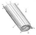
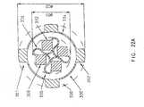
- FIG. 1is a schematic, isometric representation of a self-expanding intramedullar fixture 20, in accordance with a preferred embodiment of the present invention.
- Fixture 20is preferably constructed of two sheets 22 and 24 of resilient, biocompatible material, preferably a superelastic material or a shape memory material, as is known in the art. Nitinol is preferred.
- the fixturemay be constructed from another biocompatible metal, such as titanium, or a plastic or polymer material.
- Sheets 22 and 24are initially rolled tightly together into a cylindrical form. Each sheet of this compacted form is tightly rolled (as generally shown in Figure 2A ), and fixture 20 is inserted, in this compacted form, into the intramedullar cavity of a bone ( Figure 3B ), as described below. When the fixture is then released inside the bone, the resilience of sheets 22 and 24 causes them to partially unroll into an expanded state (as generally shown in Figure 2B ), so that fixture 20 expands radially outward to assume an increased diameter, as shown in Figure 1 .
- outer edges 26 and 28 of sheets 22 and 24, respectively,are formed so that when fixture 20 is released inside the bone, the edges bend radially outward, as shown in Figure 1 . Edges 26 and 28 will then engage an inner surface of the bone surrounding the intramedullar cavity, so as to hold fixture 20 firmly in place and prevent sliding or rotation of the bone relative to the fixture.
- edge 26is bent at an acute angle
- edge 28is bent at an oblique angle, as shown in the figure, so that fixture 20 resists rotation in both clockwise and counterclockwise directions about its axis 30.
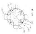
- FIGS 2A and 2Bare schematic, sectional representations of a self-expanding intramedullar fixture 36, similar to fixture 20, illustrating the principle of radial self-expansion of such fixtures, in accordance with a preferred embodiment of the present invention.
- fixture 36comprises only a single sheet 38 of self-expanding material, preferably resilient material.
- intramedullar fixtures based on the principles of the present invention, as exemplified by fixtures 20 and 36may comprise one, two, or more sheets of self-expanding material, rolled together as shown in Figures 1 , 2A and 2B .
- Figure 2Ashows fixture 36 in a first, closed configuration, in which the fixture is compressed radially inward to facilitate its insertion into the intramedullar cavity of a fractured bone, as described below.
- fixture 36preferably has an outer diameter of only about 2 mm in this closed configuration.
- Figure 2Bshows fixture 36 in a second, open configuration, which the fixture assumes after location within the cavity to fixate the bone.
- the diameter of fixture 36, in the open configuration of Figure 2Bis at least 50% greater than the diameter in the closed configuration of Figure 2A . More preferably, the diameter in the open configuration is approximately twice the diameter in the closed configuration.
- the diameter in the open configurationis preferably approximately 4 mm.
- the large diameter difference between closed and open configurationsis advantageous in that it facilitates insertion of fixture 36 into the bone in the closed configuration through a hole of minimal size made at or near the end of the broken bone.
- sheet 38preferably comprises a superelastic material, preferably Nitinol, having a thickness of about 0.2 mm.
- the superelasticity of sheet 38causes fixture 36 to expand until outer edges 39 of the sheet engage the inner bone surface surrounding the intramedullar cavity, to exert strong outward radial force on the bone.
- Sheet 38may comprise shape memory material, such as Nitinol, which is produced, as is known in the art, so as to have the open form shown in Figure 2B and to be normally in the austenitic state at body temperature.
- shape memory materialsuch as Nitinol, which is produced, as is known in the art, so as to have the open form shown in Figure 2B and to be normally in the austenitic state at body temperature.
- the force exerted in rolling up sheet 38preferably causes the material to assume a state of stress-induced martensite. In this state, the material is relatively flexible and elastic, making it easier to insert fixture 36 into the bone.
- the stress on sheet 38is reduced, and the material reverts to its normal, substantially rigid austenitic state. The rigidity of the material in this state facilitates firm fixation of the bone.
- the shape memory materialmay have a critical temperature in the range between room temperature and body temperature, preferably around 30°C. As described above, the shape memory material is formed so that in its austenitic state (i.e. above the critical temperature), it has substantially the open, expanded form shown in Figure 2B . Below the critical temperature, i.e. before insertion or fixture 36 into the bone, the shape memory material is in a martensitic state, in which it is relatively flexible and elastic and is compressed into the closed configuration shown in Figure 2A . When the fixture is inserted into the bone, it is warmed (e.g. by body heat) to above the critical temperature, whereupon it opens and assumes its substantially rigid, austenitic state. A heating element may be brought into contact with the fixture once it is inside the bone, for example, as illustrated in Figure 3B and described below, to hasten its expansion and state change.
- a heating elementmay be brought into contact with the fixture once it is inside the bone, for example, as illustrated in Figure 3B and described below, to hasten its expansion and
- FIGS 3A-3Care schematic, sectional illustrations showing the insertion of a fixture 20 into intramedullar cavity 40 of a fractured bone 42, in accordance with a preferred embodiment of the present invention.
- a fixture 20into intramedullar cavity 40 of a fractured bone 42, in accordance with a preferred embodiment of the present invention.
- devices and methods in accordance with the principles of the present inventionmay be applied in the fixation of other long bones (e.g. the humerus), with appropriate adaptations for the differences in size and mechanical strength required of the bones, as will be apparent to one of ordinary skill in the art.
- a stylette 46is inserted into a lumen 47 within a cannula 48.
- cannula 48preferably comprises a syringe needle. Stylette 46 and cannula 48 are then introduced percutaneously into intramedullar cavity 40 through an opening 45 at the end of bone 42, and past a fracture site 44 in the bone.
- a small incisionmay be made through the skin and soft tissues, to visualize the bone, and a hole may be drilled in the bone for insertion of the cannula therethrough. Drilling such a hole is the preferable method for inserting fixtures, in accordance with some preferred embodiments of the present invention, particularly for larger bones, such as the humerus. Drilling the hole before inserting the fixture also makes it easier to remove the fixture, if desired, after the bone has healed.
- stylette 46is withdrawn, and fixture 20, in its compressed, closed configuration, is passed into lumen 47 of the cannula.
- a plunger 43is used to push the fixture into the needle and hold it in place.
- Cannula 48is then fully withdrawn, leaving fixture 20 in cavity 40, with the fixture extending across fracture site 44.
- Fixture 20then expands or is expanded to substantially fill cavity 40, as shown in Figure 3C .
- the fixtureself expands in the self expandable embodiments disclosed herein.
- the fixtureis expanded using external force or energy.
- plunger 43may optionally comprise a heating element for heating fixture 20 to above the critical temperature.
- fixture 20After fixture 20 is positioned and anchored firmly in place, plunger 43 is withdrawn through opening 45, and the skin wound made by or for cannula 48 is allowed to close. Within a short time after completion of the procedure illustrated in the figures, the subject is able to mobilize fractured bone 42.
- the mechanical strength of fixture 20also reinforces the bone against axial and lateral forces that may be exerted on the bone. Moreover, the risk of post-operative infection is minimized since no surgical devices or appliances are left protruding through the skin, in contrast to the expandable intramedullar fixtures known in the art.
- the devicecan be covered with a sheath so as to prevent bone ingrowth and facilitate subsequent device removal.
- FIG 4Ais a schematic, isometric view of another self-expanding intramedullar fixture 50, in accordance with another preferred embodiment of the present invention.
- Fixture 50comprises a plurality of longitudinal ribs 52, connected by a plurality of circumferential struts 54.
- Ribs 52 and struts 54preferably comprise resilient material, preferably superelastic material, or alternatively, shape memory material as described above.
- Figure 4Ashows fixture 50 in a substantially open configuration, which the fixture assumes when it is located inside the bone and allowed to expand.
- FIG 4Bis a schematic, sectional illustration, showing fixture 50 in a closed or constricted configuration for insertion of the fixture into the bone.
- a long, cylindrical holding pin 56(seen in sectional view in Figure 4B ) is inserted gradually along central axis 30 of the fixture.
- each circumferential strut 54is, in turn, bent inward across axis 30.
- Pin 56passes through and "captures” or locks the struts in place as they are bent, thus preventing the struts from snapping back to their outward circumferential position.
- struts 54are bent inward and captured by pin 56, ribs 52 are drawn inward as well, as shown in Figure 4B .
- the fixtureBy passing pin 56 along the entire length of axis 30 through fixture 50, the fixture is brought into the closed configuration, wherein its outer diameter is substantially reduced.
- the diameter or dimension of the fixture in the closed configuration of Figure 4Bis reduced to no more than half the diameter in the open configuration shown in Figure 4A .
- fixture 50Once fixture 50 has been inserted into the intramedullar cavity of a bone (for example, cavity 40 of bone 42, as illustrated in Figures 3A-3C ), pin 56 is removed. Upon removal of the pin, struts 54 spring back to their original, circumferential positions, and the fixture resumes the open configuration shown in Figure 4A .
- fixture 50may, if desired, be made of shape memory material, which in its normal, austenitic state maintains the open configuration with substantial rigidity. As struts 54 are bent, they assume a state of stress-induced martensite, returning to the austenitic state when the stress is removed as pin 56 is removed. As discussed above, if desired, this device can be covered with a sheath or sleeve (such as an expandable flexible polymer) to prevent bone ingrowth.
- a sheath or sleevesuch as an expandable flexible polymer
- FIG. 5another self expandable bone fixator is shown in Figure 5 .
- the preferred material for this deviceis Nitinol, although the device can also be made from a polymer, stress-induced martensite (SIM), smooth tin, or other suitable materials.
- SIMstress-induced martensite
- Figure 5Ais a schematic, end view of this self-expanding intramedullar fixture 60 in an open configuration.
- Fixture 60is preferably formed of resilient material, more preferably superelastic material, as described above.
- the fixturecomprises a plurality of leaves 62, 66, 68, 70, 72, 74, 76 and 78, extending radially outward in a spiral pattern about axis 30 of the fixture, the leaves extending from a central, generally tubular portion 63.
- each of the leavesextends outward at a different angle about axis 30 (as measured off of a single reference line, not shown, extending from the axis to a point located at 0 (zero) degrees on the circumference).
- the leavesengage the inner surface of the intramedullar cavity of a fractured bone (for example, surface 49 of cavity 40, as shown in Figures 3A-3C ), in order to hold fixture 60 in place and fixate the bone.
- Each of the leaveshas a base 67, which forms a part of tubular portion 63 of the fixture, and an inward-curved end portion 64.
- FIG. 5Bis a schematic illustration showing a flat sheet of resilient material 65, which is cut in preparation for fabrication of fixture 60, in accordance with a preferred embodiment of the present invention.
- Leaves 62, 66, 68, 70, 72, 74, 76 and 78are cut out of sheet 65 in a stairstep pattern, i.e. each leaf presents a step-like extension, as shown in the figure.
- the leavesare then rolled up, one after the other.
- the leavesare rolled about axis 30, in the direction indicated by arrow 79, so that in the closed configuration shown in Figure 5C , the leaves will expand to the shape shown in Figure 5A .
- Figure 5Cis a schematic, sectional illustration showing fixture 60 in the closed configuration, in preparation for insertion of the fixture into the intramedullar cavity.
- Holding pin 56as described above with reference to Figure 4B , is inserted along axis 30 of fixture 60.
- Curved end portions 64 of leaves 62, 66, 68, 70, 72, 74, 76 and 78are bent inward and hooked around pin 56.
- Fixture 60remains in this closed configuration as long as pin 56 is in place.
- the devicemaintains a smaller external diameter than the open configuration, to facilitate insertion of the device into the bone.
- fixture 60After insertion of the fixture in the intramedullar cavity, pin 56 is withdrawn, and the resilience of the leaves causes them to spring outward, so that fixture 60 resumes the open, larger diameter, configuration shown in Figure 5A .
- this larger diameterbone fixation and support is provided as previously described above.
- the devicecan also expand by heating, taking advantage of the material's shape memory properties. As with the other embodiments of the invention disclosed herein, it can be used in treatment of both intramedullary and intravertebral support.
- FIG. 6is a schematic illustration of another expandable intramedullar fixture 80, comprising a balloon 82, shown here in a deflated state, in accordance with an alternative preferred embodiment of the present invention.
- Balloon 82can be formed of a flexible, biocompatible plastic, for example, a sleeve of Dacron fabric, as is known in the art, sealed shut at a distal end thereof.
- Fixture 80preferably includes strong, resilient longitudinal wires 84, made of biocompatible material (most preferably stainless steel), for strengthening balloon 82.
- Wires 84may preferably be woven into the Dacron fabric of balloon 82, for example.
- Balloon 82is connected via an inlet port 86 to an inflation tube 88.
- Balloon 82can also be constructed from metal having one extremity sealed shut, the other extremity being provided with a valve.
- balloon 82can likewise have longitudinal wires or bars, as discussed above.
- the ballooncan have a thin metal wall between the longitudinal wires or bars, this thin metal preferably being bent inwardly so as to reduce the balloon profile and diameter during insertion.
- FIGS 7A-7Dare schematic, sectional illustrations showing the use of balloon fixture 80 in fixating fractured bone 42.
- a hole 45is first made in the end of fractured bone 42 to provide access to the bone's medulla.
- fixture 80is then inserted through hole 45 into intramedullar cavity 40 using cannula 48.
- cannula 48a thin hollowed out space can be created within the medulla prior to insertion of the fixture, in the preferred embodiment, insertion of the fixture 80 using cannula 48 itself creates the intermedullary space.
- inflation tube 88is used in place of plunger 43 (shown in Figure 3B ) to push fixture 80 through the cannula 48 and position the fixture 80 within cavity 40.
- the fixturebe provided with a medial longitudinal canal so as to allow insertion of the inflatable rod over a guide wire.
- Longitudinal wires 84help to hold balloon 82 in a narrow, elongated profle, so as to ease the insertion of the balloon into cavity 40.
- fixture 80is left extending through a substantial portion of cavity 40, across both sides of fracture site 44, as shown in Figure 7B .
- Inflation with the non-compressible fluidis preferably accomplished with an inflator having a pressure gauge.
- the pressure gaugeis monitored during the inflation of the fixture. When the pressure begins to rise in slope, it indicates that good alignment has been achieved of the rod within the bone's inner surface. Later, to remove the device, a hub for fixture retrieval is inserted over the proximal part of the fixture where the valve is positioned. This hub can be used to open the valve, allowing fluid to be removed so that reduction of fixture diameter can be achieved to facilitate removal.
- balloon 82is inflated via tube 88.
- the balloonis first inflated with water (e.g. saline), whereupon the fixture expands to fill substantially the entire width of cavity 40.
- watere.g. saline
- wires 84 and the boneare both visible, so that proper positioning of the fixture 80 can be verified.
- Balloon 82is then emptied of the saline and filled with a biocompatible, solidifying fluid which fills the balloon 82 so as to fixate the bone.
- the solidifying fluidcomprises a monomer material that polymerizes within the balloon, or alternatively, a two component cement, such as an epoxy.
- the fluid's solidificationis preferably catalyzed by the increased temperature and/or humidity within the bone medulla.
- inlet port 86is sealed shut, and tube 88 is withdrawn.
- the solidified fluidfully hardens, anchoring fixture 80 in place and fixating bone 42.
- Wires 84provide additional mechanical strength to fixture 80, particularly improving the fixture's resistance to lateral, bending and shear forces.
- a sheath or cupcan be located over the valve, after insertion, to prevent bone ingrowth within or into the valve.
- the skin wound made for insertion of fixture 80 into bone 42is closed and allowed to heal. Bone 42 may then be mobilized within a very short time after the bone fixation surgery.
- fixture 80may be removed through hole 45 or via an osteotomy elsewhere in bone 42.
- at least a portion of the solidified fluidis drilled out or broken up, and the fixture is then collapsed and removed.
- liquid or gelare merely suctioned or pumped out, for collapse and removal of the fixture.
- the valvecan merely be opened so that when the rod is pulled out of the bone through a narrow canal, the rod will be caused to reduce in diameter.
- Figures 8-11Further preferred embodiments are shown in Figures 8-11 .
- Figures 8 and 9illustrate embodiments in which the balloon is designed so that only a portion is inflated with fluid. As shown in the figures, the shaded sections represent the fluid filled areas of the balloon.
- the expandable bone fixation devicecan be formed based on a lattice configuration. Representative embodiments are shown in Figure 10 , which illustrates a series of perspective views of two embodiments of the configuration in both the small, constricted, diameter and the large, expanded, diameter. These embodiments can be inserted into the bone taking advantage of the self-expanding principle inherent to superelastic or shape memory alloys discussed above.
- the devicesare each formed in a meshwork or lattice configuration.
- Figures 10(a) and 10(b)provide an illustration of a first embodiment of this lattice configuration
- Figures 10(c) and 10(d)provide an illustration of a second embodiment.
- a first, small profile stateis illustrated for each of the devices in which the devices are compressed into small diameters d. This reduced diameter facilitates ease of insertion into the bone.
- Figures 10(b) and 10(d)show the respective first and second embodiments, each with increased diameters d' after expansion. After insertion into bone, the properties of the superelastic or shape memory material cause the device to expand outward into these expanded diameters.
- first and second embodimentsdiffer in the design of their respective lattices.
- the first embodiment( Figures 10A and 10B ) is contructed as a lattice which is initially in a configuration that is substantially diamond shaped, and which expands outward into a series of expanded diamonds or squares.
- the second embodimentis constructed as a reduced-size lattice having a series of rectangular shaped subunits, which expand outward to form a series of interconnected hexagons (six- sided polygons), like a honeycomb.
- FIG 11illustrates a further preferred embodiment of the present invention.
- the fixatoris constructed as a round or square device which can be set to two heights, H1 and H2.
- Rigid rods or bars 85are hinged at points 83.
- the height of the devicecan be changed, thereby providing its expansion and fixation properties at its new height, H2 (compare Figure 11B to Figure 11A ).
- intramedullar fixturesin accordance with the principles of the present invention may be produced and used in fixating substantially any of the body's long bones.
- Such fixturesmay be used, for example, both in small bones of the hands and feet, such as the metacarpal and metatarsal bones, and in large bones, such as the femur.
- the fixtures and minimally-invasive methods of bone fixation in accordance with the present inventionhave the advantages of minimizing operative trauma and damage to soft tissues. Furthermore, because no parts of the fixtures are left protruding through the skin, the risks of infection are reduced, and the patient is able to mobilize the broken bone more quickly than the prior art.
- a syringeis inserted into the damaged disc area, with or without a stylet.
- a surgical toolis then used to "nibble" at or erode soft tissue only, including the vertebral periosteum, without damaging the bone itself.
- the expandable intervertebral spacer or another expandable spacerpercutaneously through the hollow syringe, as with the embodiments of the intramedullary fixation device disclosed above.
- the function of this spaceris to stabilize the vertebrae and to enhance bone growth up to bone fusion between the two vertebrae adjacent to the intervertebral spacer.
- intervertebral bone spacer 125 or 130are illustrated (although the device can be used for intramedullary fixation as well).
- the intervertebral spacer 125 or 130is initially inserted through the syringe in the compressed, reduced diameter form illustrated in Figure 13B .
- This spacerlike the intramedullary fixation device, is initially maintained in a reduced diameter profile for insertion into the intervertebral space. This ability to percutaneously insert the spacer, due to the reduced diameter profile of the spacer, allows major surgery to be avoided, as disclosed above, and reduces the trauma and risk of infection to the patient.
- the spacer 125 or 130Upon insertion of the intervertebral spacer 125 or 130 into the intervertebral space, the spacer uncoils to reach the expanded state shown in Figure 13C , by virtue of its expandable properties.
- the spacer 125 or 130is preferably made of biocompatible metal or polymer and is initially inserted through the syringe in the compressed, reduced diameter form illustrated in Figure 13B .
- the spacercan also be made of materials such as annealed 316-L stainless steel, shape memory alloy (e.g. Nitinol), or a polymer such as polyurethane. In the event that annealed material is used, the spacer 125 or 130 will require the assistance of an expander to expand its diameter after insertion.
- This expandercan be a balloon inserted through the syringe which is inflated to dilate the spacer to the diameter of the intervertebral space.
- the expandercan be a mechanical expander which is inserted into the spacer lumen and which self-expands, or which is expanded using outside assistance. In the event that a self expandable material is used for the spacer, this expander can still be employed merely to assist with the expansion, if desired or needed.
- the spacer 125 or 130is provided with a series of pores or gaps 120 in its surface. These pores 120 (which are circular, rectangular, or any other shape) enhance vertebral stability by allowing bone growth through the pores, and eventually direct fusion between adjacent vertebrae, while the spacer is in place. Protrusions or spikes 153 can also be provided, which penetrate the bone surface and assist with fixation and stabilization of the spacer.
- spacer 130is provided with a locking mechanism such as one or more locking fingers 115 or teeth 119.
- This locking mechanismfurther maintains the expanded diameter of the intervertebral spacer 130 and retards or prevents compression of the spacer 130 back to its reduced diameter state.
- Figure 13Aillustrates the use of one or more locking fingers 115 in spacer 130.
- Locking fingers 115 or teeth 119resist retrograde movement of the leading edge 122 or contraction of the spacer 130 by trapping the leading edge 122 within the "V" shaped gap of the locking finger 115, or the groove of one of the teeth 119.
- the spacerin response to the application of force to spacer 130 while it rests between the vertebrae, the spacer exhibits flexible compressive characteristics yet resists undue compression, due to the counteraction provided by the locking mechanism.
- the combination of the thorough cleaning of the bone surface, the special spacer porous design with its flexible compressive characteristics, and the implanted bone graftenables and enhances bone fusion in the intervertebral space and stabilization of vertebrae up to the point of bone fusion.
- Figures 14A and 14Bare schematic illustrations showing a balloon prosthesis 140, for insertion in the intervertebral disc space of a patient, in accordance with a preferred embodiment of the present invention.
- Figure 14Ais a top view of the prosthesis
- Figure 14Bis a sectional view, in which the balloon is shown in an inflated state, as described below.
- Balloon prosthesis 140comprises two circular pieces of biocompatible fabric or polymer 142, preferably having a diameter approximately equal to the diameter of an intervertebral disc.
- Fabric 142is preferably woven out of strong, inert, synthetic fibers, such as Dacron, Gore-Tex or other fiber materials known in the art.
- the fabricmay comprise bioabsorbable material, known in the art, either by itself or, preferably, interwoven with the inert fibers.
- the fabricpreferably has a rough weave, so that after implantation of prosthesis 140, as described below, bone ingrowth into the prosthesis is enhanced.
- the two pieces of fabric 142may be replaced by any suitable biocompatible material, as long as it is flexible, elastic and strong enough to be inserted into the disc space and inflated to a sufficient pressure, as described below.
- ground bone substance(taken, for example, from the patient's pelvic bone) be placed on the outer surface of fabric 142, before and/or after implanting prosthesis 140. Moreover, a substantial quantity of the bone substance may preferably be contained in the hollow at center 146 of the balloon. The ground substance further enhances the desired bone growth and fixation to bone.
- the balloonfurther be provided with protrusions 153 in its upper and lower surfaces so as to stick and/or penetrate up and down into the bone surface. These protrusions prevent balloon movement and achieve better stabilization of the balloon.
- Fabric pieces 142are sealed to one another around their outer edge 144 and at their circular center 146.
- heat sealingcan be used, a technique which is known in the art.
- one or more strong, resilient wires 152preferably stainless steel wires, are interwoven with fabric 142 to reinforce the structure of balloon 140.
- Wires 152are shown in Figures 14A and 14B at outer edge 144 of the balloon, where the presence of the wires is helpful in preventing rupture of the balloon along the seam between pieces 142.
- the wiresare also useful in stiffening the balloon, to make it easier to manipulate and position within the disc space, as described below.
- such wiresmay be interwoven at other locations in fabric pieces 142. They can also be useful in positively locating the wire when used in conjunction with X-ray imaging.
- a fluid port 148is left open at a point along edge 144.
- An inflation tube 158is fitted and sealed to port 148. When a pressurized fluid is injected through tube 158 into port 148, the fluid fills and inflates space 150 within balloon 140 to a predetermined fluid pressure.
- Figure 15is a schematic, isometric view illustrating the implantation of prosthesis 140 into a disc space 162 intermediate two vertebrae 164 and 166, in accordance with a preferred embodiment of the present invention.
- Prosthesis 140is implanted in disc space 162 to replace an injured natural disc, e.g., a disc that has been herniated.
- a cannula 160is inserted percutaneously into disc space 162, in a lateral approach. Substantially all of the natural disc matter is removed from the disc space prior to implantation of the prosthesis.
- the prosthesisIn order to insert prosthesis 140 into cannula 160, the prosthesis is rolled into a narrow, elongate, generally cylindrical form, as shown in Figure 15 .
- the prosthesisis fed in this shape through the cannula and into now eroded out disc space 162.
- inflation tube 158is stiff enough so that it can serve to push the prosthesis through the cannula. Otherwise, other surgical probes known in the art may be used for this purpose.
- prosthesis 140makes it possible to implant the prosthesis through narrow cannula 40.
- Disc prostheses known in the artcannot be compacted in this manner nor can they be subsequently opened and inflated within disc space 162, as described below.
- prosthesis 140can be implanted percutaneously, without the need for substantial skin incisions, laminectomy or dissection of large masses of muscle.
- Figure 16is a schematic, sectional view showing vertebrae 164 and 166, seen along a coronal plane therethrough, with prosthesis 140 positioned in disc space 162 between the vertebrae.
- Correct placement of prosthesis 140 in disc space 162is preferably verified by visualization of the vertebrae, disc space and prosthesis, most preferably using an open magnetic resonance imaging (MRI) system.
- MRImagnetic resonance imaging
- X-ray imagingmay be used to observe the position of wires 152 relative to vertebrae 164 and 166.
- a narrow endoscopeas is known in the art, may be inserted into or adjacent to disk space 162 to visually observe the prosthesis.
- the prosthesisafter insertion of prosthesis 140 as shown in Figure 16 , the prosthesis is inflated with saline, so that it assumes the form shown in Figure 14B . Inflating the prosthesis allows it to be visualized in substantially the shape and position that it will have when filled with solidifying fluid, as described below. If the prosthesis is seen to be incorrectly positioned, it can easily be deflated, repositioned and then reinflated. After correct positioning is verified, the saline is removed and the prosthesis deflates.
- a biocompatible solidifying fluidis injected through tube 158 and port 148, to inflate the prosthesis.
- the solidifying fluidcomprises a bone epoxy, known in the art, such as DuPuy Orthopedic Bone Cement, produced by the DuPuy Company, England.
- the solidifying fluidmay comprise a polymerizing monomer.
- Prosthesis 140is inflated to such pressure as is necessary to maintain an anatomically correct spacing between vertebrae 164 and 166. Because of the elasticity of fabric pieces 142 that form the balloon and the equalization of the pressure of the fluid throughout space 150 (as seen in Figure 14 ), the balloon will tend naturally to maintain a generally uniform pressure on the surfaces of vertebrae 164 and 166 that adjoin disc space 162 and to hold the vertebrae in an anatomically correct mutual orientation.
- vertebrae 164 and 166, along with prosthesis 140 and surrounding structuresare imaged, most preferably using MRI, as described above, to verify that the spacing and orientation of the vertebrae are correct.
- port 148is sealed and tube 158 is removed, preferably by twisting and pulling tube 158 back through cannula 160.
- FIGS 17A and 17Bare coronal and axial sectional views, respectively, showing prosthesis 140 inserted and inflated within disc space 162.
- the prosthesishas been inflated with solidifying fluid 170, and tube 158 has been detached and removed, as described above.
- Vertebrae 164 and 166remain substantially intact, including lamina 172, thereof.
- vertebrae 164 and 166will grow into disc space 162, around and through the prosthesis.
- ground boneis placed on the outer surfaces of prosthesis 140, and particularly in the hollow at center 146 thereof, in order to aid this bone growth.
- the growth of vertebrae 164 and 166will cause them to fuse together, so that the bones are permanently stabilized and protected from any further injury.
- prosthesis 140is implanted percutaneously in a lateral approach
- inflatable disc prostheses in accordance with the principles of the present inventionmay also be implanted using other surgical techniques known in the art, such as open and laparoscopic surgical procedures with an anterior or posterior approach.
- Figures 18A-18CAdditional preferred embodiments of the present invention are shown in Figures 18A-18C . These embodiments present flat annular top and bottom walls, like a washer, in contrast to the donut (toroidal) shape shown in Figures 14-17 . Further preferred embodiments are also described below in the following section regarding metal balloons for intramedullar fixation and disc prostheses.
- a small openingis made from outside a bone to accommodate insertion of a device percutaneously into the bone (whether it be long or small bone); or, to replace a disc, a hole is made in the intervertebral space.
- the deviceincludes a metallic balloon.
- the balloonis made from thin metal such as Titanium, Tantalum, Stainless Steel (e.g. S.S. 316L), Platinum, another medical grade metal, or so forth.
- the balloonis preferably constructed with a balloon wall thickness between 10 and 300 microns, although wall thicknesses which are greater or less than these dimensions are possible, as well.
- the ballooncan be constructed with several metal strings or rods to provide the balloon with greater strength against axial, bending and rotational forces, and to provide the balloon with greater rigidity that eases its manipulation and insertion into the patient.
- the rodscan be connected to the exterior or interior surface of the balloon (e.g. by soldering, milling or as a part of the balloon).
- soldering, milling or as a part of the balloonFor example, to produce the the metal balloon and the rods they could all be annealed or could all be cold worked. Alternatively, the rods could be cold worked, while the balloon itself is annealed to allow easier expansion after insertion within the bone. This can be done by producing a one piece cold worked rod and annealing afterwards only the thin wall part of the metal balloon.
- the balloon extremitiescan be manufactured by soldering, spot welding, laser welding or any other suitable way of connecting the metal cone to each extremity of the device.
- the outer surface of the balloonmay be abrasive or roughened with protruding edges engaging the bone surface to anchor the fixture firmly in place and prevent sliding or rotation of the parts of the broken bone in the intramedullar embodiments, or, likewise provide non-movement in the intervertebral embodiments.
- This systemhas the advantage of not requiring or using interlocking screws in intramedullar nailing.
- the ballooncan comprise a biocompatible polymer. Additionally or alternatively, the balloon can comprise an outer thin surface of metal as described above and an inner surface of biocompatible plastic, polymer or fabric.
- the balloonOnce the balloon has been inserted into its proper place within the bone or adjacent to the vertebrae, it is then inflated with a biocompatible material.
- a liquidis used as the inflation fluid in intramedullary fixation, and a biocompatible solidifying fluid is used as a disc prosthesis.
- liquids for intramedullary fixationwater, gel or air are preferred.
- a solidifying fluidcan be used, if desired.
- the inflation fluid(either for the intramedullar nail or the disc prosthesis) is a filler material which is itself capable of expansion.
- This filler materialis preferably capable of changing its volume or stiffness in response to an external stimulus.
- the external stimuluscan be a magnetic field, an electric field, radiation and/or temperature.
- Rheological materials, polyelectrolyte gels or other suitable expandable materialswhich change their volume or stiffness in response to external stimuli can be used as the filler material.
- a biocompatible solidifying fluid or other noncompressible fluidis used in the preferred embodiments.
- this solidifying fluid or noncompressible fluidcomprises a monomer material that polymerizes within the balloon, or alternatively, a two-component cement, such as epoxy. This provides a prosthesis with sufficient strength to replace the disc.
- This inflation fluidis placed in communication with the lumen of the balloon, while also being under pressure from an external source, causing the balloon to expand radially outward to fixate the bone.
- the balloonis then sealed, e.g. by using a valve, and the external fluid source is disconnected.
- a protective cupbe provided over the valve to shield and protect the valve from bone ingrowth.
- the disc prosthesisbecomes extremely strong and can replace the disc.
- This ballooncan also be provided with one or more tunnels or holes between surfaces that allow the vertebral bone surfaces to contact each other between two adjacent vertebrae, thereby enabling those two vertebrae to undergo fusion.
- the outside surface of the metal balloonis stronger than the vertebrae, which keeps the vertebrae from eroding.
- the outside surface of the metal ballooncan also be abrasive or roughened, and be provided with protruding edges to engage the vertebrae and anchor the fixture firmly in place, preventing sliding or rotation.
- the ballooncan comprises a biocompatible plastic which is of sufficient strength that it is stronger than the vertebrae. Additionally or alternatively, the balloon comprises an outside surface of metal as described above and an inner surface of biocompatible plastic or fabric.
- the ballooncan be deflated by opening the valve and removing the liquid, thereby easing the device's removal.
- the prosthesismay be left in place permanently.
- Figures 20-23illustrate some preferred embodiments of the present invention. These embodiments are useful with respect to the intramedullary nail, and the balloon embodiments of the nail, in particular, although features of these embodiments can also be used in conjunction with self-expanding or expandable devices and/or in conjunction with the other intervertebral devices and prostheses disclosed herein. Thus, the valve, fixation elements, etc. can also be used with the other inventions disclosed in the present disclosure.
- Figure 20illustrates an additional preferred embodiment of the intramedullary nail or fixture of the present inventions. As shown in the figures, it is preferred that the nail be constructed having longitudinal, outwardly extending, bars 300.
- Figure 20Bis a cross sectional view illustrating the protuberance of longitudinal bars 300 above the surface of intramedullary nail 310.
- These longitudinal bars 300may be placed upon a portion of the length of intramedullary nail 310, although it is preferred that they extend along all, or substantially all, of the length of the intramedullary nailing device.
- four longitudinal barsare provided, located at 90 degree intervals around the nail's circumference. Alternatively, other numbers of longitudinal bars can be provided as well.
- Longitudinal bars 300act as fixational elements, improving the function of the device and facilitating bone healing.
- the longitudinal bars or fixational elements 300When the intramedullar nail is inflated, the longitudinal bars or fixational elements 300 are pressed against the inner surface of the bone cortex, preventing rotational movement between the broken parts of the bone and preventing bending.
- the addition of these fixational elementspresents an advantage over standard intramedullar nails as no interlocking is needed due to the fact that the longitudinal rods prevent rotation. This further stabilizes the bone, and facilitates the healing process.
- These longitudinal bars or fixational elements 300can be provided to various embodiments of the present invention, whether the self expandable, balloon expandable, or balloon embodiments, disclosed herein.
- Figure 21illustrates additional aspects of a preferred embodiment of the intramedullar fixture disclosed herein.
- a metal balloon or fixture 320is utilized having a pipe or body 321 and a distal end cover 323.
- Metal balloon or fixture 320is further provided with a valve 318 located at proximal tip 330 of the fixture for controlling the passage of fluid into and out of fixture 320.
- Valve 318includes ventilation pin 325, O-ring 326, and spring 327 housed within a head cover 322, and terminating in a head cap 328. Head cover 322 and head cap 328 shield valve 318, preventing bone growth into the valve.
- a high pressure fluide.g. saline
- salinea high pressure fluid
- salineis first inserted or pumped into the intramedullar fixture through valve 318.
- Pumping of the saline into the balloon through the valvecauses fixture 320 to expand in diameter, as shown in comparison of Figure 21B to Figure 21C .
- the valveprevents fluid from escaping the intramedullar fixture, maintaining the fixture in the expanded state for the length of time needed. If desired, the fixture can be subsequently deflated using valve 318 to release fluid or saline from the fixture.
- FIG. 21DA further embodiment of the invention is illustrated in Figure 21D .
- the inventionis illustrated as located within a bone 313.
- the fixtureis provided with a tubular element 311 for location in the vicinity of the bone fracture.
- Element 311is of a fixed diameter less than the diameter of inflated fixture segments 315.
- the diameter of element 311is fixed such that upon radial expansion of the fixture, element 311 prevents or restrains expansion of the fixture so that it cannot contact the inner bone surface.
- segments 315expand to a diameter which contacts the inner surface of the bone, element 311 prevents the fixture surrounded by the element from achieving the degree of expansion achieved by the remainder of the fixture.
- the devicefor example, can be provided with a ring for restraining expansion of in that area. This embodiment is particularly useful to prevent "butterfly fractures", or complications in fractures with multiple bone fragments.
- FIG 22AAn embodiment of the intramedullar nail of the present invention is disclosed in Figure 22A.
- Figure 22Aconsists of two cross sectional views of a fixture embodiment, both before and after expansion, these views being superimposed on each other (for appreciation of relative constricted and expanded diameters).
- the constricted intramedullar nailincludes a curved or undulated surface, preferably having longitudinal bars 300 located thereon. It is preferred that intramedullar fixture, before expansion, have its surface be curved or folded inward to form a series of connected bulbous sections 336. In the preferred embodiment, the bulbous sections form a clover like configuration in the compressed state, as shown in the four leaf clover configuration illustrated in Figure 22A .
- intramedular nail 330maintains a compressed diameter D 1 .
- Compressed diameter D 1is a small diameter such that the intramedullar nail is suitable for insertion into the bone through a small hole in the bone or through a syringe, as discussed above.
- the intramedular nail 330is maintained within the bone at an expanded diameter D 2 .
- Expanded diameter D 2is a larger diameter, measured from the outside surface of longitudinal bar 301 to the outside surface of opposing longitudinal bar 302, this diameter being sufficient such that the longitudinal bars are pressed up against the inner wall of the desired bone.
- Figure 22Bis a further embodiment of the invention, illustrated in the same manner as in Figure 22A .
- one or more hairpin loops or arcs 337are provided between longitudinal bars 300.
- four longitudinal bars 300are provided, each at 90 degrees to each other, with one hairpin loop 337 centrally located between and connecting each adjacent pair of longitudinal bars.
- One or more or no hairpin loopscan be provided between any or all of the pairs of adjacent longitudinal bars, if desired.
- the intramedullar nailcan also be provided with a medial longitudinal canal, bore or tunnel 344.
- This canal 344faciliates the insertion of the nail into the bone, allowing the insertion procedure to be performed using a guide wire.
- the medial canal 344is threaded over the guide wire to allow the fixture to be easily guided into the appropriate position during insertion into the bone, and to allow the guide wire to be pulled out once positioning has been completed.
- a retrieval mechanismcan be provided which is mounted on the tip of the implanted nail to assist in withdrawal of the nail from the bone.
- the valvecan be opened, releasing the high pressure within the nail and thereby allowing the diameter to decrease in preparation for removal.
- the above descriptions of the present inventiondescribe minimally invasive insertion of intramedullary and intervertebral fixation devices, intervertebral bone spacers and supporters, intervertebral disc prostheses, and methods of treatment. It must be understood that, although preferred embodiments are described, the embodiments of the present inventions are directed to expandable fixation and prosthesis devices which expand either spontaneously or by an expander inserted through its lumen to an expansion level that enables percutaneous insertion of the bone fixator.
Landscapes
- Health & Medical Sciences (AREA)
- Orthopedic Medicine & Surgery (AREA)
- Engineering & Computer Science (AREA)
- Biomedical Technology (AREA)
- Life Sciences & Earth Sciences (AREA)
- Neurology (AREA)
- Public Health (AREA)
- General Health & Medical Sciences (AREA)
- Animal Behavior & Ethology (AREA)
- Veterinary Medicine (AREA)
- Heart & Thoracic Surgery (AREA)
- Transplantation (AREA)
- Vascular Medicine (AREA)
- Chemical & Material Sciences (AREA)
- Surgery (AREA)
- Cardiology (AREA)
- Oral & Maxillofacial Surgery (AREA)
- Nuclear Medicine, Radiotherapy & Molecular Imaging (AREA)
- Molecular Biology (AREA)
- Medical Informatics (AREA)
- Physics & Mathematics (AREA)
- Mechanical Engineering (AREA)
- Crystallography & Structural Chemistry (AREA)
- General Physics & Mathematics (AREA)
- Materials Engineering (AREA)
- Thermal Sciences (AREA)
- Metallurgy (AREA)
- Organic Chemistry (AREA)
- Physical Education & Sports Medicine (AREA)
- Dispersion Chemistry (AREA)
- Prostheses (AREA)
- Surgical Instruments (AREA)
- Medicinal Preparation (AREA)
Abstract
Description
- The present invention relates to systems for percutaneous bone and spinal stabilization, fixation and repair, including intramedullar bone and vertebral fixtures.
- Intramedullar fixtures for use in repair of broken bones are well known in the art. Such fixtures, which generally have the form of long, narrow nails, are inserted longitudinally into the bone's intramedullar cavity, so as to connect together and jointly brace two or more sections of a severely fractured bone, and thereby promote healing.
- A fixture of this type must have a radial diameter large enough to firmly and rigidly hold its position after insertion. The problem of holding the fixture in position is complicated by the fact that the intramedullar cavity of most long bones is not uniform, but is, rather, narrow at the middle of the bone and flares out at the ends. The problem is further complicated by the fact that a rod inserted into such canal does not normally provide stabilization for rotational and bending movement.
- Frequently, the bone medulla must be reamed out before insertion of the fixture, to make room for the fixture therein. Such reaming destroys tissue within the bone and may consequently retard proper healing. Therefore, various intramedullar nails and fixtures have been designed to have a narrow shape during insertion and then to expand radially outward to fit the shape of the intramedullar cavity and hold firmly therein.
- For example,
U.S. Patent No. 4,204,531 to Aginsky , which is incorporated herein by reference, describes an intramedullar nail with an expanding mechanism. The nail includes an outer tubular sheath, a rod-shaped element longitudinally movable in the sheath, and an expandable element having two or more spreadable longitudinal branches at the front (inner) end of the nail. The nail is inserted into the medullar cavity of a bone, front end first, leaving the rear end of the nail to protrude out of the end of the bone. The rod-shaped element is then pulled back, causing the branches of the expander element to spread radially outward, thereby anchoring the front end of the nail within the intramedullar cavity. - Similarly,
U.S. Patent No. 4,854,312 to Raftopoulous et al. , which is also incorporated herein by reference, describes an expanding intramedullar nail. The nail is formed of two elongate members. A first one of the members has an articulated channel, which slidably engages the second member. After the nail is inserted into the intramedullar cavity, the second member is slid longitudinally relative to the first, causing the end of the second member to bend, so that the nail spreads laterally within the cavity and is anchored in place. U.S. Patent No. 4,313,434 to Segal , which is incorporated herein by reference, describes a method for fixation of fracture of long bones using a flexible, inflatable bladder inside the intramedullar cavity. A small opening is drilled in the bone, and the bladder is inserted through the hole into the intramedullar cavity. The bladder is then inflated with sterile air and sealed, to fixate the bone. After the fracture has healed, the bladder is deflated and removed.U.S. Patent Nos. 5,423,850 and5,480,400 both to Berger , which are incorporated herein by reference, describe methods and devices of bone fixation using a balloon catheter. The catheter, with the deflated balloon at its distal end, is inserted into the intramedullar cavity, past the fracture site. In the '850 Patent, the balloon is inserted by guiding it along guide wires that are fed through the cavity, before introducing the catheter. Once fully inserted in the cavity, the balloon is inflated to anchor it in place, and the catheter is tightened against the balloon to provide compression to the fracture.- The intramedullar fixtures and methods of implantation thereof that are described in all of the above-mentioned patents require that a portion of the expandable intramedullar fixture be left protruding through the patient's skin. Such protruding portions, however, increase the likelihood of postoperative infection and interfere with mobilization of the bone. Accordingly, it is an object of the present invention to provide methods and devices which eliminate the need for such protrusions.
- In addition to fracture of large bones, fracture of long small bones is also a very common occurrence. However, a simple treatment which allows early mobilization with fracture stabilization is not currently available.
- Varela and Carr in an article entitled "Closed Intramedullary Pinning of Metacarpal and Phalanx Fractures," in Orthopedics 13 (2), 213-215 (1990), which is incorporated herewith by reference, describe one method for fixation of finger fractures using K-wires. To fixate a fractured finger bone, several such wires, slightly bent, are inserted one after another into the intramedullar cavity. Each wire is inserted through a respective hole drilled near one end of the bone. Typically, between two and five wires are needed to fixate the bone. After insertion, the wires are cut off flush with the bone surface, and the skin is closed over the insertion site.
- However, the treatment of choice today for fractured small tubular bones is the insertion of a thin metal rod (intramedullary nailing). To prevent this rod from moving, an edge of the rod is left projecting from outside the bone, such as is done in metatarsal bone fracture nailing where the end of the rod projects out of the finger tip. This fixation, however, prevents the patient from using the finger or the broken bone limb. It also does not allow good rotational stabilization. In addition, it can also result in infection due to communication between the bone medulla and the exterior of the body.
- Some patents and methods for the fixation of small bones without use of protruding rods currently exist in the art. Examples include, for example,Lewis, R.C., Jr., Nordyke, M., Duncan, K., Clinical Orthopedics Related Research, 1987, 214 (85-92);Nordyke, M.D., Lewis, R.C., Janssen, H.F., Duncan, K.H. J. of Hand Surgery, 1988, 13/11 (128-134);Varela, C.D., Carr, J.B., Orthopedics, 1990, 13/2: 213-215; and,
WO 94/12112 US 4204531 , andUS 4854312 . - One method in particular is described in an article "Expandable Intramedullary Device for the Treatment of Fractures in the Hand", Royce C. Lewis et al., Clinical Orthopedics and Related Research, Tech. Ortho., 1989, 1:18-91. In this article, an expandable intramedullary nail is inserted after the fractured bone is opened and the nail is inserted through the broken part. The nail is inserted through the fracture and not through the bone extremities. Yet, there still exists a need for a percutaneous minimal trauma insertion of an internal fixator for small bones which does not necessitate exposure of the bone surface.
- Intramedullar nailing through the finger tip is also discussed in the article "Closed intramedullary pinning of metacarpal fractures", Varela, C.D.; Carr, J.B., Orthopedics, 1990, 13/2: 213-215. However, this nailing does not involve an expandable nail.
- Numerous of the bone fixation patents mentioned above involve implantation of different metal devices (i.e., Nitinol, Titanium, etc.).
Another possibility is to use a detachable inflatable balloon as an expandable intramedullary bone fixator. There are patents that exist today for bone fixation with a balloon, but these do not provide intramedullary nailing. They provide only a joining effect as in the pulling of one broken bone towards the other. Examples of these includeU.S. Patent Nos. 5,423,850 and5,480,400 (described above). - Accordingly, a variety of significant shortcomings exist in the present art of fracture stabilization. To address these problems, the present inventors have provided an intramedullary nailing which is accomplished using a variety of inventions desribed below. For example, by using a detachable intramedullary balloon located at the middle of the fracture, and extended across both bone segments, a improved device is provided which addresses the numerous shortcomings of the prior art. Such devices provide the patient with a rapid post-surgery fracture stabilization resulting in mobilization of the limb and reduced chance for infection, as well as the possibility of removal after bone healing, if needed.
- Back pain is a widespread ailment which is often attributed to disc pathologies and vertebral instability. Nowadays, the treatment of choice of spinal fusion involves disc removal followed by implantation of a plate with or without screws into the intervertebral space (See e.g.,
U.S. Patent No. 5520690 ,U.S. Patent No. 5522816 , andU.S. Patent No. 5529899 ). The procedure also involves implantation of a bone graft in the intervertebral space. - Patents and applications employing artificial intervertebral discs currently exist, although they have not yet been proven successful in patients (
U.S. Pat. No. 4,759,769 ;WO 92/14423 WO 90/00037 WO 96/37170 U.S. Pat. No. 4,904,260 andU.S. Pat. No. 5,645,598 for example). A bone graft is then implanted to facilitate spine fusion. - All procedures utilizing the above method require actual opening and dissection of the back and/or the abdomen or performing the procedure laparoscopically. Accordingly, there is currently a need in the art for a percutaneous non-laparoscopic type minimally invasive technique to facilitate and improve the current method for spine fusion.
- In addition, the disc ablation procedure may involve the interposition of a spacer in the intervertebral space to support the vertebrae until spine fusion is achieved by osteogenesis. The existing spacers are constructed with a fixed diameter according to the space needed to be kept in the intervertebral area. Although one spacer has been disclosed which expands by rotating a screw, it only expands upwards and downwards, and therefore still has a large insertion profile. This does not allow for the insertion of the device percutaneously in a minimally invasive technique. As discussed in greater detail below, there is a need for a spacer or prosthesis that is created with a small diameter and which can expand radially once implanted. In addition, as also discussed below, there is also a need for an intervertebral tissue extractor which can likewise function percutaneously for use in the procedures described.
- Intervertebral disc prostheses are also known in the art. Such a prosthesis is generally inserted into the intervertebral space following the removal of all or a part of the disc matter from the space. Upon insertion, the prosthesis holds two adjacent vertebrae apart from each other, so as to maintain the vertebrae in an anatomically correct spacing and orientation. Following surgery to implant the prosthesis, bone generally grows from the vertebrae into and around the prosthesis, thereby holding the prosthesis firmly in place and preventing undesirable motion of the vertebrae relative to each another.
U.S. Patent Nos. 4,772,287 and4,904,260 to Ray et al. , which are incorporated herein by reference, describe prosthetic disc capsules having a generally cylindrical shape and containing a gel material having properties similar to those of the disc matter. After removal of a portion of the disc matter, two such prosthetic capsules are implanted in the disc space, one on either side of the sagittal axis of the spine. The capsules may be implanted in a deflated state and then inflated with the gel to a pressure sufficient to hold the adjoining vertebrae apart.- To implant the prosthetic disc capsules in the disc space, it is necessary to open the patient's back and perform a partial laminectomy to gain access to the disc space. Such open laminectomy is a major surgical procedure, with attendant risks, side effects and long recovery time. Other disc prostheses, as described, for example, in
U.S. Patent Nos. 3,875,595 ,4,349,921 ,3,867,728 ,4,554,914 ,4,309,777 ,3,426,364 , and4,636,217 , and incorporated herein by reference, similarly require major surgery for implantation thereof. - In response to the risks and lengthy recovery period associated with open surgery for treatment of bulging or herniated discs, an alternative, minimally-invasive surgical technique of percutaneous diskectomy has been developed. In percutaneous diskectomy, a narrow cannula is inserted into the disc space in a lateral approach through a small incision in the patient's side. The lateral approach to the disc obviates the need to cut through bone and/or substantial amounts of muscle, as required by other surgical methods known in the art. Surgical tools are passed through the cannula to cut away and remove disc material, so as to relieve the outward pressure of the disc on surrounding nerves and thus to alleviate the pain caused by the bulging or herniated disc.
- Percutaneous diskectomy can be performed as an outpatient procedure and, when successful, allows the patient to return to full activity after only a short recovery period. The procedure is successful only in about 70% of cases or less, however, and does not allow the full range of treatment afforded by open back surgery. For example, disc prostheses and methods of implantation of such prostheses that are known in the art are not suitable for use in the percutaneous approach.
- The vertebrate spine is the axis of the skeleton, on which the body parts hang. The bony vertebral bodies of the spine are separated by intravertebral discs, which serve as a cushion between vertebral segments of the axial skeleton. These discs comprise a fibrous annulus and a nucleus, which is a gel-like substance, contained within the annulus. A disc herniation occurs when the tissue of the nucleus bulges out of the annulus. The herniated nucleus may exert pressure on a spinal nerve adjacent to the disc, resulting in pain or loss of muscle control. The normal procedure in such cases is to remove the herniated disc tissue in open surgery, but this is a major procedure with long recovery and potentially serious side effects.
- In response to the dangers and complications of open spinal surgery, minimally invasive procedures for removal of herniated tissue have been developed. One type of such procedure as described above, is percutaneous diskectomy, in which herniated tissue of the nucleus of the disc is removed from the patient's body. Apparatus for such procedures is described, for example, in
U.S. Patent No. 5,131,382 , which is incorporated herein by reference. The nuclear tissue is removed thorough a cannula, which is inserted through a small incision, preferably in the patient's side, into the intervertebral space. By making the incision as small as possible and entering the body laterally, rather than dorsally, trauma to the patient is minimized. Removal of the herniated tissue is a long process, however, frequently requiring removal and reinsertion of resection tools many times. - In some diskectomy procedures, after the tissue is removed, a disc prosthesis is inserted to replace the nucleus and possibly the annulus, as described above, and in
PCT publication WO 96/11643 - It is an object of the present invention to provide improved devices and methods for intramedullar fixation of fractured bones.
- It is an object of the invention to provide devices and methods for fixation of the humerus and other long bones.
- It is an object of the invention to provide devices and methods for fixation of fractures of the phalanx bones or other small bones of the hands and feet.
- It is an object of the present invention to provide devices and methods which allow intramedullar bone fixation using minimally-invasive surgical procedures, so as to generally reduce operative trauma and allow speedier post-operative recovery.
- It is an object of the present invention to provide devices and methods for percutaneous bone and spinal stabilization, fixation and repair.
- It is a further object of the present invention to provide a percutaneously inserted intramedullary bone fixation device for the stabilization of fractured bones.
- It is an object of some aspects of the present invention to provide devices and methods for intramedullar fixation that allow mobilization of a bone within a short time of fixation thereof.
- It is an object of other aspects of the present invention to reduce the risk of post-operative infection following intramedullar fixation.
- It is a further object of the present invention to provide inflatable balloon fixation devices for intramedullary nailing.
- It is a further object of the present invention to provide fixation devices having a valve for inflation and deflation of the devices.
- It is a further object to provide intramedular devices having fixation elements for anchoring the devices against the inner surface of a bone.
- It is a further object of the present invention to provide methods and devices which provide for a less invasive surgical treatment of intervertebral spine fusion.
- It is a further object of the present invention to provide a minimally invasive method and device for treatment of intervertebral spine fusion which includes the extraction of intervertebral tissue and the placement of an intervertebral spacer.
- It is an object of the present invention to provide an improved disc prosthesis for implantation in the intervertebral disc space.
- It is a further object of some aspects of the present invention to provide a disc prosthesis suitable for implantation using minimally invasive methods of percutaneous diskectomy. It is another object of these aspects of the invention to provide devices and methods for use in percutaneous implantation of the prosthesis.
- It is a further object of the present invention to provide a prosthesis whose size can be increased long after implantation, without the need for a second surgical procedure.
- It is another object of some aspects of the present invention to provide an improved method of minimally invasive diskectomy.
- Further objects of the invention will become apparent upon reference to the drawings, description and/or claims herein.
- In a first aspect, the present invention provides a medical device for treatment of broken bones having an intramedullary cavity, the bone being provided with a bore formed through the exterior surface of the bone and extending into the intramedullary cavity, comprising:
- a bone fixture for insertion through the bore of the bone and into the intramedullary cavity, said bone fixture comprising a diameter-expandable, metallic tube having an exterior circumferential surface, said tube having a reduced first diameter for insertion through the bore and into the intramedullary cavity and a second expanded diameter, wherein when said bone fixture radially increases in diameter from said reduced first diameter to said second expanded diameter, at least a portion of said exterior circumferential surface coming into contact with a portion of the side wall of said intramedullary cavity upon said bone fixture increasing to said second expanded diameter.
- In a second aspect, the present invention provides a medical treatment device for treatment of broken bones having an intramedullary cavity, comprising:
- a bone fixture for treatment of a broken bone, said bone fixture having a reduced diameter and an expanded diameter, wherein said bone fixture is capable of increasing in size from said reduced diameter to said expanded diameter.
- Preferably, the reduced diameter is sufficiently small such that said fixture can be inserted into the bone through a hole which is smaller in diameter than the medulla of the bone. More preferably, the reduced diameter is sufficiently small such that said fixture can be inserted into the bone through a syringe.
- Preferably, the expanded diameter is sufficiently large such that said expanded diameter extends across substantially the entire width of the intramedullary cavity of the bone.
- The fixture may further comprise a valve or longitudinal bars. More preferably the fixture comprises a curved surface before expansion, said surface being curved to form a series of connected bulbous sections. The fixture may have a circumferential wall comprising four bulbous sections separated by thin wall sections.
- The fixture may comprise at least two of said longitudinal bars.
- The fixture may comprise at least one hairpin loop between said two longitudinal bars, more preferably four longitudinal bars and four hairpin loops.
- In a third aspect, the present invention provides a medical treatment device for treatment of broken bones having an intramedullary cavity having a width, comprising:
- a bone fixture having a reduced diameter, and an expanded diameter;
- Preferably said fixture is sized for treatment of a broken bone of the hand, foot, leg or arm.
- The fixture may be substantially tubular in shape after expansion.
- The fixture may expand to adjust to and rest against the inner surface and shape of the bone cavity upon said expansion.
- Preferably, the fixture increases in diameter by at least 40% when said fixture increases from said reduced diameter to said expanded diameter. The fixture preferably comprises at least one sheet of said self-expanding material, more preferably at least two sheets.
- The fixture preferably comprises a generally cylindrically rolled spiral structure in said reduced diameter, more preferably said spiral structure at least partially unrolls as said fixture expands from said reduced diameter to said expanded diameter.
- The sheet of self-expanding material preferably has at least one bent edge.
- The sheet may have an outer, circumferential surface and at least one bent edge, said bent edge protruding radially from said outer, circumferential surface, preferably at least two bent edges protruding radially from said outer, circumferential surface.
- Even more preferably, the bent edges are bent at different angles to the outer, circumferential surface of said sheet.
- The fixture may comprise a self-expanding material, an elastic material, a superelastic material, shape memory metal, Nitinol, titanium, or a polymer.
- The fixture may comprise stress-induced martensite in said reduced diameter and preferably austenite in said expanded diameter.
- A holding device comprising a pin may be used to retain said device is said first, reduced diameter.
- The fixture may expand from said reduced diameter to said expanded diameter upon application of heat.
- The fixture may be cylindrical in said expanded diameter and comprises a plurality of longitudinal ribs and substantially arcuate circumferential struts, said ribs being interconnected by said struts. More preferably, the fixture comprises a central axis, said struts being bent inward about a midpoint toward said central axis when said fixture is in said reduced, diameter. The fixture may also comprise a circumferential wall, said fixture comprising a plurality of openings in said circumferential wall.
- In the medical treatment device of the third aspect of the present invention, the fixture may comprise a plurality of leaves staggered in stepwise fashion about a central longitudinal axis, each of said leaves having an inner end and an outer end, each of said inner ends extending outwardly from said central longitudinal axis. More preferably, the outer ends curve radially inward.
- Even more preferably, the fixture comprises a substantially tubular shape when said fixture is maintained in said reduced diameter and possibly further comprises a holding device in the form of a removable pin contacting said inner ends of said leaves for maintaining said fixture in said reduced diameter.
- In a fourth aspect, the present invention provides a medical treatment device comprising:
- an intramedullar nail, said intramedullar nail comprising an inflatable metal balloon. Preferably said inflatable metal balloon comprises an initial, reduced-diameter, size which is smaller in diameter than the bone medulla. More preferably, said inflatable metal balloon is bent into said initial, reduced-diameter size.
- In a fifth aspect the present invention provides a medical treatment device for treatment of a broken bone having an intramedullary cavity, comprising:
- an intramedullar fixture, said fixture comprising at least a first segment and a second segment, said segment of said fixture having a reduced diameter and being capable of expanding in size from said reduced diameter to an expanded diameter, further provided with a restraint means which prevent said second segment from expansion to said expanded diameter.
- Preferably said restraint means comprises a ring for restraining expansion of said second segment.
- The expanded diameter is preferably sufficiently large such that said fixture will extend across substantially all of the width of the intramedullary cavity of the bone.
- In a sixth aspect, the present invention provides a medical treatment device for treatment of broken bones having an intramedullary cavity, comprising:
- an expandable intramedullary fixture, said fixture having a lumen, said lumen being at least partially filled with a filler material capable of expansion, said filler material being capable of changing its volume or stiffness in response to an external stimulus.
- Preferably said external stimulus is selected from the group consisting of: a magnetic field, an electric field and radiation. The external stimulus may even be temperature.
- The filler may be rheological material or a polyelectrolyte material.
- In a seventh aspect, the present invention provides a medical treatment device for treatment of broken bones having an intramedullary cavity, comprising:
- an intramedullar fixture, said fixture being constructed of two interleaved sheets of material, said sheets being initially rolled tightly together into a cylindrical form for insertion into a broken bone.
- In an eight aspect, the present invention provides a medical treatment system for treatment of bones, comprising:
- a bone fixture having a reduced diameter and an expanded diameter;
- a cannula for insertion of said bone fixture into a bone, said cannula comprising a lumen, said bone fixture being of a sufficiently small size in said reduced diameter that said bone fixture can be inserted into said bone by use of said cannula.
- In a ninth aspect, the present invention provides a medical treatment device for spinal treatment, comprising:
- an intervertebral bone spacer, said bone spacer having a first, reduced dimension, and a second, expanded dimension.
- Preferably, said bone spacer comprises pores for allowing bone growth therethrough.
- The bone spacer may comprise protrusions for penetrating the surface of a vertebral bone. More preferably, the intervertebral bone spacer further comprises a locking mechanism for retarding compression of said spacer.
- In a tenth aspect, the present invention provides a medical treatment device for spinal treatment, comprising:
- an intervertebral disk prosthesis, said prosthesis comprising an inflatable balloon, said balloon may be toroidal, said balloon may comprise thin metal walls.
- In an eleventh aspect, the present invention provides a medical treatment device for treatment of broken bones having an intramedullary cavity, comprising:
- a self expanding intramedullar fixture, said fixture comprising shape memory metal and a plurality of longitudinal ribs.
Figure 19 summarises the classes of methods and devices for bone fixation and spacing which are presented herein in accordance with the present invention, devices for bone fixation, spacing and prostheses may also be referred to, for brevity, as bone therapy devices. Likewise, the term prosthesis, implant, and fixture are used interchangeably herein.- As described below, in accordance with the present invention, these devices and their associated methods can be divided into 3 general categories or groups: (I) Self Expandable Implants; (II) Implants Expandable by External Power; and (III) Solid Phase Formation Devices. Devices in accordance with the present invention can be constructed according to the embodiments of each of these groups, and can be employed for either intramedullary or intervertebral applications.
- Group I: Self Expandable Implants. Self expandable implants and related methods utilize the energy stored within the implant material itself, such that when a holding mechanism or restraining force is released from the implant, the implant material reverts to its original shape and/or diameter. In the preferred embodiments, the material is restrained in a small diameter, for use during implantation, and reverts to a larger diameter after implantation, for fixation of the bone. Implementation of this method is preferred using a material which exhibits shape memory such as Nitinol, taking advantage of the properties of Stress Induced Martensite, although other materials can be used, as well. The holding mechanism utilized can be incorporated into the device or around it.
- Group II: Implants Expandable by External Power. Implants which are expandable by external power utilize energy which does not exist in the device but originates from an outside source, to change the shape of the implant. Numerous different forms of external power can be utilized in accordance with the present invention. In the preferred embodiments, at least four alternative types of external power are contemplated:
- (1) Heat. Various materials and/or configurations of material can be used in which the application of external heat to the implant (whether from a mechanical source, or body heat itself) causes a change in shape of the implant. In the preferred embodiments, this results from the properties of the implant materials. In particular, shape memory alloys can be used to cause a device to attain a new shape from a small to a larger diameter.
- (2) Balloon Expandable Devices. In a second series of external power embodiments, an expandable balloon is used to change the shape of an implant. In these embodiments, the inflation of a balloon causes plastic deformation of the implant material, resulting in deformation of the device.
- (3) Balloon Devices. In a third series of external power embodiments, the implant device is itself a balloon. This balloon device is inflated using hydraulic pressure by the insertion of fluid into the balloon's interior, thereby enlarging the device's diameter. In these embodiments, the pressure of the fluid within the sealed balloon provides the energy to support the balloon in its expanded shape.
- (4) External Force Devices. In a fourth series of external power embodiments, a mechanism is utilized for application of force to the implant. In these embodiments, the system is designed such that force is transferred inwards, which acts eccentrically from the implant lumen causing an increase of the implant diameter.
- Group III. Solid Phase Formation Devices. In these devices, a material which solidifies (e.g. by polymerization) is inserted into a balloon, forming a solid which has a new shape. This material can have two-componential cement properties, and can be formed of epoxy or polymer. The material is compressed into the balloon and solidifies by change in temperature or humidity.
- As disclosed herein, each of these types of devices and methods can be used for intramedullary or intervertebral treatments. Moreover, while different embodiments of the present inventions are discussed in separate sections below, it will be apparent that the disclosures of each section are meant to supplement each other and interrelate. Accordingly, the disclosures of each of the embodiments provided herein may be further relevant to and supplement the disclosures of other embodiments. As examples of the present inventions, a variety of different bone therapy devices and methods are disclosed in further detail below.
- In the intramedullary fixture embodiments of the present invention, a radially-expandable intramedullar fixture is inserted percutaneously into a fractured bone. The fixture is inserted through a hole in the bone which is smaller in diameter than the medullar canal. In the preferred embodiments, the fixture is preferably inserted, using a syringe, through the end of a fractured bone and into the medulla. During insertion, the fixture is maintained in a closed configuration, i.e. a first, reduced diameter. The fixture is inserted so that it extends across the site of the fracture in the bone. When the fixture is properly placed within the bone, the syringe is withdrawn. It is highly preferred that the fixture be placed entirely within the bone, with no outward protrusion.
- Once in place, the fixture expands radially outward, assuming an open configuration, i.e. a second, expanded diameter, and anchoring itself in place. Upon expansion, the radially expandable device extends through the bone, across both sides of the fracture, thus functioning as an intramedullary bone fixator. The expanded fixture thus holds the pieces of the broken bone together and provides reinforcement against both axial and lateral forces on the bone. Fixtures as those disclosed herein can be provided and sized for long bones, such as the femur, tibia, fibula, humerus, ulna and radius or for smaller bones, such as a phalanx.
- After the fixture has been inserted, the skin wound made by the syringe is closed and allowed to heal over the bone. With the employment of the minimally invasive percutaneous procedure, which excludes all post-implantation communication with a contaminated skin surface, the present invention fixates the fractured bone rapidly, and allows mobilization of the patient's limb in minimal time and with a lower infection risk. Thus, when the fixture is used to repair a broken bone in an extremity (for example, a phalanx fracture in a finger), the patient can begin to move the extremity very shortly after the insertion. Such rapid mobilization promotes healing and reduces muscle atrophy. The patient regains use of the broken bone as quickly as possible. Even more importantly, healing proceeds without the need for extensive physiotherapy, which is typically required after the prolonged periods of immobilization commonly encountered when intramedullar nails known in the prior art are used. Furthermore, since there is no fixture left protruding through the skin after the insertion, post-surgical infection and other complications are reduced.
- In the preferred embodiments, the implant is made of bio-compatible metals like Nitinol, titanium, S.S. 316 or suitable polymers. Preferably, after insertion, the radial expansion of the fixture is such that its diameter substantially increases. Thus, the diameter can increase by at least 20%, by 40%, by 50%, or more if desired. This large factor of expansion is advantageous in that during insertion, the unexpanded fixture is narrow enough to fit easily into the bone medulla. In contrast, the fixture expands after placement such that its diameter fills substantially all of the intramedullar cavity (i.e., such that the fixture extends across substantially all of the width of the bone) so that the bone is firmly fixated.
- Thus, more generally, the initial size of the fixture maintains a reduced diameter small enough to be passed through a needle so as to be inserted into a bone through a syringe, and is capable of expanding to an expanded diameter large enough to fill substantially all of the intramedullary cavity of the bone in question, for fixation of the bone. The fixture is preferably substantially rod like (i.e. tubular in shape) after expansion.
- Fixtures in accordance with preferred embodiments of the present invention generally fixate the bone more firmly than K-wires used for this purpose, as described in the above-mentioned article by Varela and Carr. The fixtures of the present invention require formation of only a single hole in the bone for intramedullar insertion, rather than multiple holes as is the case with K-wires.
- In some preferred embodiments of the present invention, the intramedullar fixture comprises a self-expanding structure, as described in Group I above. In the context of the present patent application and the claims, the term "self-expanding" or "self-expandable" is used to refer to types of fixtures and to materials from which such fixtures are fabricated. The term is used herein to mean that once the fixture is inserted into the intramedullar cavity, it expands radially outward due to mechanical force generated by the fixture itself. This mechanical force may be due to potential energy stored in the fixture, for example, as a result of radially compressing the fixture before inserting it into the cavity. Additionally or alternatively, as described below, the fixture may expand due to heat absorbed by the fixture in the intramedullar cavity. As disclosed below, certain preferred configurations and materials are used to provide this self-expanding effect. Intramedullar fixtures in accordance with these preferred embodiments differ from expandable intramedullar fixtures known in the art, which require external application of mechanical force to the fixture to cause the fixture to expand within the intramedullar cavity.
- Before introduction into the bone, the self-expanding fixture is preferably compressed radially inward into a closed, reduced diameter configuration and is inserted into the syringe in this closed, reduced diameter configuration. After the syringe is inserted and the fixture is put into place, the syringe is withdrawn, leaving the fixture behind in the bone. The fixture then expands radially outward, to bear against and fixate the bone. Thus, the structure and the material from which it is produced, as described below, should generally be sufficiently flexible to be compressed into the closed, reduced diameter configuration, but rigid enough to fixate the bone firmly in an open, expanded configuration.
- In some preferred embodiments of the self-expanding implants, the fixture comprises a resilient or elastic, biocompatible material. Preferably, the resilient or elastic material is a superelastic or shape memory material, for example, Nitinol, or another metal, such as titanium, or else a polymer material. The fixture is fabricated, as is known in the art, so as to exert an outward radial force when compressed.
- In other preferred embodiments of this type, the fixture comprises a biocompatible shape memory material, likewise such as Nitinol. Preferably, the material is chosen and prepared, as is known in the art, so that upon compression of the fixture into its closed, reduced configuration, the material assumes a state of stress-induced martensite, wherein it is relatively flexible and elastic. When released inside the bone's intramedullar cavity, the fixture springs back to its desired shape, the open, expanded configuration, and the material assumes an austenitic state, wherein it is substantially rigid and firmly fixates the bone.
- The structure of the fixture itself can be formed by tightly rolling together one or more sheets of self-expanding material, preferably superelastic or shape memory material, as described above, to form a generally cylindrical spiral structure. After insertion of the fixture into the intramedullar cavity, the spiral partially unrolls as it expands radially outward, until it has expanded to substantially fill the cavity. Preferably, at least one edge of each of the one or more sheets of the material is bent so as to protrude radially outward from the outer, radial surface of the spiral. As the spiral expands, these protruding edges engage the inner surface of the bone, adjoining the medullar cavity, so as to anchor the fixture firmly in place and prevent sliding or rotation of sections of the bone fixated by the fixture. More preferably, two or more of the edges are bent at different angles, in order to prevent rotation of the bone in either a clockwise or a counterclockwise direction.
- In other preferred embodiments of this type, the fixture includes a holding device, for example, a pin, which is fitted into the fixture before insertion of the fixture into the bone. The holding device is fitted into the fixture while the fixture is held mechanically in its compressed, closed configuration and then continues to hold the fixture in this configuration. After the fixture has been inserted and properly placed in the intramedullar cavity, the holding device is withdrawn, and the fixture self-expands radially outward to anchor itself in place and fixate the bone.
- As an alternative to a self-expanding implant, the implant can be constructed to be expandable by the application of energy or external power. For example, the shape memory material can be chosen and prepared, as is known in the art, so as to have a critical temperature of approximately 30°C. Thus, at room temperature, the material is normally at least partially in a martensitic state, so that the fixture remains flexible and elastic before its insertion into the bone. When inserted into the bone, the implant becomes exposed to body temperature, at which temperature, the material assumes at least a partially austenitic state, and the fixture is substantially rigid.
- In such embodiments, wherein heat is applied to the implant to cause it to expand, instead of, or in addition to the use of body temperature, after the fixture is inserted into the intramedullar cavity and the syringe is withdrawn, an external heat source can be used for the application of heat. This can be accomplished, for example, through a heating probe that is brought into contact with the fixture. The heat causes the fixture to expand radially outward and to become substantially rigid, so as to anchor itself in place and fixate the fractured bone. The heating probe or other heat source is then removed.
- In other preferred embodiments of the present invention (whether falling within Group I or Group II), the fixture comprises a tube, made of stiff, resilient material, as described above, and having a plurality of openings through its radial wall, so that the wall has substantially the form of a meshwork. The meshwork preferably comprises a plurality of longitudinal ribs, interconnected by generally arcuate circumferential struts. When the fixture is radially compressed, the struts are bent inward, toward the central axis of the tube. The holding device, preferably a pin, is inserted along the axis and holds the struts in their bent configuration, thus preventing the fixture from expanding. When the pin is removed, with the fixture inside the bone, the struts resume substantially their arcuate shape, with the fixture either self-expanding radially outward, or expanding due to the application of energy, until the fixture engages the inner bone surface adjoining the intramedullar cavity.
- Over time, after insertion of the fixture in the intramedullar cavity, bone tissue will tend to grow into and through the openings in the mesh-like wall of the fixture, so that the overall structure of the bone will be strengthened.
- In another of the embodiments of the invention, the fixture comprises a plurality of leaves, which are bent so that the inner end of each leaf normally extends radially outward, away from a central, longitudinal axis of the fixture. The leaves are arranged along the axis in a generally spiral pattern, wherein each leaf extends outward at a different angle relative to a reference point on the axis from one or more other leaves that axially adjoin it. Preferably, the outer end of each leaf curves radially inward. Before inserting the fixture into the bone, the fixture is compressed by bending the leaves inward, to form a narrow, generally tubular shape. The holding device, preferably a pin, in then inserted along the axis of the tubular shape, so as to engage and hold the inward curved outer ends of the leaves and prevent their radial expansion. After the fixture has been inserted into the intramedullar cavity, the pin is withdrawn, and the leaves snap back radially outward, engaging the inner bone surface and anchoring the fixture in place.
- Alternatively, in other embodiments of the present invention involving the application of external energy, a balloon may be inserted inside the fixture and inflated to expand the fixture. After the fixture is expanded, the balloon is preferably deflated and withdrawn although it can also be left implanted.
- In another embodiment of the invention, the same intramedullary bone fixator is made of an inflatable balloon.
- In other embodiments of the present invention, the fixture itself comprises a balloon, which is inserted into the intramedullar cavity. The balloon can be formed from a tube of a flexible, biocompatible plastic, for example, Dacron fabric, as is known in the art, sealed shut at a distal end thereof.
- This balloon fixture is also preferably inserted using a syringe. After the placement of the syringe in the intramedullary space, a sleeve can be inserted therein, through which the balloon is inserted. Once the balloon is positioned and the sleeve and syringe are taken out, the balloon is inflated and detached of the inflating device which is also taken out. The same procedure can also be performed without a sleeve, with or without a guide wire.
- Once the balloon is in place, it is inflated to fixate the bone. This can be accomplished with a biocompatible solidifying fluid under pressure from an external source, causing the balloon to expand radially outward to fixate the bone. The balloon is then sealed, and the external fluid source is disconnected.
- Preferably, the solidifying fluid comprises a monomer material that polymerizes within the balloon, or alternatively, a two-component cement, such as an epoxy. Such solidifying fluid materials are known in the art. The fluid's solidification is preferably catalyzed by the increased temperature and/or humidity within the bone medulla.
- Alternatively, when a non-solidifying non-compressible fluid is used, if the need should arise, the balloon can be perforated and removed utilizing the same basic technique (albeit in reverse) with which it was inserted.
- In some of the preferred embodiments, the balloon can also include an internal structure, for example, resilient longitudinal wires. These wires can be fabricated from metal, and can extend lengthwise down the inner side of the balloon. While the balloon is deflated, the structure holds the balloon in a narrow, elongated, substantially closed configuration, so as to ease the insertion of the balloon into the bone. After the balloon has been inserted and inflated, the structure provides additional mechanical strength to the fixture, especially against shear forces. This gives the balloon the elasticity as well as the strength of a bone fixator, once the balloon is inflated in the intramedullary space.
- Preferably, after the balloon is inserted into the bone, the balloon is filled with non-compressible fluid. In the preferred embodiments, the balloon has a valve to prevent fluid from escaping (while also allowing fluid to be released, once desired). Upon filling the balloon with fluid, it expands so that it substantially fills the intramedullar cavity. Preferably, an X-ray image is taken of the bone with the balloon inside (preferably while the balloon is still in a partially or non-expanded state). The balloon's internal structure is then observed in the image to ascertain that the balloon is properly positioned, before fully inflating the balloon with the solidifying fluid. In particular, the longitudinal wires will show up on the X-ray image so that proper positioning can be verified.
- In the preferred embodiments of the invention, a metal balloon is utilized which has a unidirectional valve, and which is inflated with a high pressure fluid (preferably saline). The balloon is contructed having longitudinal bars which act as fixational elements, so that when inflated, the fixational elements or bars are compressed against the inner surface of the bone cortex, preventing rotational movement between the broken parts of the bone and preventing bending. This embodiment presents an advantage over standard intramedullar nails as no interlocking is needed due to the fact that the longitudinal rods prevent rotation. The nail may also have a medial longitudinal canal to facilitate performing the insertion procedure over a guide wire. During removal, the retrieval device is mounted on the tip of the implanted nail to open the valve, releasing the high pressure within the nail and allowing device diameter decrease.
- Fixtures and methods of bone fixation in accordance with the embodiments of the present invention described herein are advantageous for fixation of fractured long bones or short bones. For example, the fixtures of the present invention may be used for fixation of the bones of the arms, legs, hands or feet. Thus, they may be used for fixation of the phalanges of the fingers or toes, the femur, the humerus, the metacarpals, the metatarsals, the tibia, the fibula, or so forth. It will be appreciated that fixtures in accordance with the present invention can be easily adapted to the necessary size for the broken bone required, by one of ordinary skill in the art.
- In the preferred embodiment for spine fusion, a hollow syringe is inserted through the back into the intervertebral space using an imaging technique. An intervertebral tissue eroder is then inserted through the syringe lumen. Each embodiment is provided with an eroding element for eroding soft tissue in its vicinity. The device can come in the design of a brush or a spinning wire, to which might be attached an eroding element, such as an orb with cutting edges. Rotation of the eroding element, whether the brush, the spinning wire or the orb, causes erosion of soft tissue in the eroding element's vicinity. Upon eroding the soft tissue, the intervertebral tissue extractor then sucks out or removes the eroded intervertebral tissue, creating a space into which the intervertebral spacer, together with a bone graft, is inserted. The suction or removal is achieved by use of a vacuum through the longitudinal central lumen of the extractor's rotating shaft or any other desired lumen. Suction or removal can also be effected by a screw within the same lumen that would spin in the opposite direction of the extraction device or which stays as is and takes up and out the tissue remains.
- The insertion of the intervertebral spacer (also referred to herein as an intervertebral cage), like the insertion of the intervertebral tissue extractor, is made through the hollow syringe lumen, circumventing the need for exposing the vertebra with subsequent invasive surgery.
- Once in the intervertebral space and out of the insertion syringe, the intervertebral spacer expands in diameter due to its self-expandable properties, or is expanded with an expander, thus fixating and supporting the spine. Due to its porous design, the spacer further enables bone fusion of the two adjacent vertebrae, assisted by bone graft interposition with or without bone growth factors.
- In additional embodiments of the present inventions, a disc prosthesis is provided which comprises a balloon made of a biocompatible fabric. The balloon has an inlet port which is connected to an inflation tube. Preferably the fabric comprises inert, synthetic material, such as Dacron or Gore-Tex. Alternatively or additionally, the fabric may comprise bioabsorbable material, as is known in the art, or a combination of inert and bioabsorbable materials. Further preferably, the prosthesis includes a strong, resilient reinforcing structure, for example, stainless steel wires interwoven with the fabric. Further, the balloon can have a thin wall of metal, the balloon being compressed when inserted and expanded (in the upward and downward direction) during inflation. Further, the disc prosthesis can be made of a complex of inflatable elements interconnected so that, when inflated, it expands radially and up and down, with space provided between the tubes to allow bone growth.
- After removal of some or all of the disc matter of an injured disc from the intervertebral disc space of a patient, the balloon is inserted into the disc space. (In the context of the present disclosure, the balloon prosthesis is referred to interchangeably either as the balloon or as the prosthesis.) The balloon is inserted in an at least partially deflated state, preferably completely deflated, in which state it preferably assumes a narrow, elongate shape, through a percutaneous cannula. After the balloon has been properly positioned in the disc space, a biocompatible solidifying fluid, for example, a bone cement or, alternatively, a polymerizing monomer, as are known in the art, is injected through the inflation tube to inflate the balloon. Once the fluid has hardened, the balloon remains firmly in place between the vertebrae adjoining the disc space and holds the vertebrae permanently at an anatomically suitable orientation. Also, a high pressure non-compressible fluid can be used to keep the prosthesis in its expandable state.
- Preferably, before the prosthesis is inserted into the disc space, the disc matter is removed and the bone surfaces adjoining the disc space are cleaned using an electrocautery probe. Alternatively, the disc matter may be removed and the bone surfaces may be cleaned using diskectomy methods and devices known in the art.
- Preferably, the fabric is woven so as to have a roughened, porous surface, which encourages ingrowth of the vertebral bones adjacent to the prosthesis into the fabric. Such ingrowth forms a tight bond between the bone and the prosthesis. Further preferably, ground bone matter, taken, for example, from the patient's pelvic bone, is spread on the surface of the fabric, to further encourage bone growth. Eventually, the two vertebrae on the opposite sides of the prosthesis will generally grow around and through the prosthesis and fuse together. During the period of bone growth, the presence of the prosthesis holds the vertebrae at a suitable distance and mutual orientation.
- In some embodiments of the present invention, the balloon comprises two circular pieces of the fabric having a diameter approximately equal to the diameter of the disc space in which the prosthesis is to be implanted. The two pieces of fabric can be laid one on top of the other and then sealed together around their outer edges and at their centers. An inflation tube is attached and sealed to the fluid port, which is located between the two pieces of the fabric at a point along the outer edges thereof.
- To insert the balloon into the disc space, the balloon is rolled up about an axis parallel to the inflation tube. The rolled-up balloon has the shape of a long, narrow cylinder. In this shape, the balloon is passed through the cannula into the disc space, preferably using the same cannula through which a surgical tool was previously passed to clean the disc space of disc matter. Once inside the disc space, the balloon is allowed and/or caused to unroll.
- The balloon is then filled with the solidifying fluid via the inflation tube, so that the balloon assumes a generally toroidal shape. The major diameter of the toroid, extending radially across the disc space, is, preferably, approximately equal to the diameter of the disc that the prosthesis has replaced. The minor diameter, extending axially between the two vertebrae adjoining the disc space, is controlled by increasing the inflation pressure of the fluid in the balloon until the vertebrae are held stably at the anatomically correct mutual spacing. Once the fluid has begun to solidify, the inflation tube is first sealed off and then withdrawn through the cannula.
- Alternatively, in other embodiments of the present invention, the prosthesis may comprise a balloon of any other suitable size and/or shape, for example, an ellipsoidal or crescent shape. Furthermore, two or more such balloons, of substantially smaller diameter than the radial diameter of the disc space, may be implanted and inflated side-by-side. Such smaller balloons are advantageous in that they are generally easier to insert and manipulate through the cannula than a single, larger balloon.
- In some embodiments of the present invention, after the prosthetic balloon is inserted in the disc space, but before it is inflated with the solidifying fluid, the balloon is inflated with a gas, for example, sterile air or carbon dioxide. The position of the balloon in the disc space is then visualized, to verify that it is properly placed and to correct its positioning, if necessary. Once these steps are completed, the balloon is deflated of gas and then inflated with the solidifying fluid or with high pressure fluid.
- Various methods may be used for visualizing the implantation of the balloon. Preferably, the entire procedure of percutaneous spinal treatment is performed under open magnetic resonance imaging, as is known in the art. Alternatively or additionally, an endoscope, likewise known in the art, may be inserted into or adjacent to the disc space, preferably through the same cannula that is used for insertion of the prosthesis. Further alternatively, when the balloon includes a radio opaque element, for example, the stainless steel reinforcement wires described above, the position of the balloon may be visualized using X-ray imaging, in which the radio-opaque element is visible.
- The disc prosthesis can also be constructed as a metal hollow member which is able to change its volume by high pressure fluid insertion. This metal disc is provided with protrusions in its upper and lower surfaces so as to stick and/or penetrate up and down into the vertebral bone surface. This prevents disc movement and achieves better stabilization until bone fusion is achieved.
- In one embodiment, cylindrical shaped tubes are inserted percutaneously. In another embodiment, a donut-shaped (i.e. toroidal) disc is inserted and the inner space is filled with a bone graft. In another embodiment, a tri-dimensional honeycomb shaped structure is created, preferably for expansion using multi-tubed inflation. This honeycomb shaped structure preferably has open cells, facilitating bone ingrowth through the structure.
- All of these embodiments can be filled with soldifying fluid or non-compressible fluid. If non-compressible fluid is used, it is preferred that a valve be provided so that the fluid remains at high pressure during use, but can be released from the structure, for deflation if desired. If desired, the device used to remove the prosthesis can attach to the valve to allow release of fluid therefrom.
- Although embodiments of the present invention are described with reference to minimally invasive, percutaneous spinal treatment, it will be appreciated that disc prostheses in accordance with the principles of the present invention may similarly be implanted using other surgical methods known in the art.
Figure 1 is a schematic, isometric view of a self-expanding intramedullar fixture, in accordance with a preferred embodiment of the present invention.Figure 2A is a schematic, sectional illustration showing a self-expanding intramedullar fixture in a first, closed configuration, in accordance with a preferred embodiment of the present invention.Figure 2B is a schematic, sectional illustration showing the fixture ofFigure 2A in a second, open configuration, in accordance with a preferred embodiment of the present invention.Figures 3A-3C are schematic, sectional illustrations showing the use of the fixture ofFigure 1 in fixation of a fractured bone, in accordance with a preferred embodiment of the present invention.Figure 4A is a schematic, isometric representation of another self-expanding intramedullar fixture, in an open configuration, in accordance with a preferred embodiment of the present invention.Figure 4B is a schematic, sectional illustration showing the fixture ofFigure 4A in a closed configuration, wherein a holding pin is inserted along a central axis of the fixture, in accordance with a preferred embodiment of the present invention.Figure 5A is a schematic, end view of still another self-expanding intramedullar fixture, in an open configuration, in accordance with a preferred embodiment of the present invention.Figure 5B is a schematic illustration showing preparation of material for fabrication of the fixture shown inFigure 5A , in accordance with a preferred embodiment of the present invention.Figure 5C is a schematic, sectional view of the fixture ofFigure 5A , in a closed configuration with an internal holding pin, in accordance with a preferred embodiment of the present invention.Figure 6 is a schematic representation of an intramedullar balloon fixture, in a non- inflated state, in accordance with a preferred embodiment of the present invention.Figures 7A-7D are schematic, sectional illustrations showing the use of the fixture ofFigure 6 in fixation of a fractured bone. The figures illustrate the steps of insertion of the fixture, inflation of the balloon and removal of the inflation mechanism.Figures 8A and 8B are side and sectional views, respectively, of an inflatable intramedullar fixture, in a deflated configuration, in accordance with a preferred embodiment of the present invention.Figures 9A and 9B are sectional and isometric views, respectively, of an inflatable intramedullar fixture, in an inflated configuration, in accordance with a preferred embodiment of the present invention.Figures 10 (a) - (d) are perspective views showing two devices for bone fixation in open and closed positions, in accordance with a preferred embodiment of the present invention. These devices can be opened by a transfer of heat (e.g. if they are constructed from shape memory material), can be opened by use of a balloon, or by any additional suitable mechanical method.Figures 10(a) and (b) are illustrations of a first embodiment of the device, shown in compressed and expanded configurations respectively.Figures 10(c) and (d) are illustrations of a second embodiment of the device, shown in compressed and expanded configurations respectively.Figure 11 is a schematic cross sectional illustration of a bone fixation device whose height can be mechanically varied, in accordance with a preferred embodiment of the present invention.. It is shown in closed (Figure 11a ) and open (Figure 11b ) configurations. The device can include hinges at its joints or joints that undergo plastic deformation.Figure 12 is a schematic isometric view of an expandable intervertebral spacer and intramedullar bone fixator, in accordance with a preferred embodiment of the present invention. The design is shown in the figure without a locking finger and with multiple surface openings.Figure 13A is a schematic cross sectional view of an intervertebral bone spacer and intramedullar bone fixator, in accordance with a preferred embodiment of the present invention.Figure 13B is a schematic cross sectional view of the device ofFigure 13A , shown in its compact, reduced diameter state for insertion.Figure 13C is a sectional view of a modified version of the device ofFigures 13A-B , shown in its expanded state, with multiple locking mechanisms.Figure 14A is a schematic, top view of an intervertebral disc prosthesis, in accordance with a preferred embodiment of the present invention.Figure 14B is a schematic, cross-sectional view of the prosthesis shown inFigure 14A .Figure 15 is a schematic, isometric illustration showing the insertion of the prosthesis ofFigures 14A and 14B into the intervertebral disc space of a patient, in accordance with a preferred embodiment of the present invention.Figure 16 is a schematic, sectional view in a coronal plane, showing the placement of the prosthesis ofFigures 14A and 14B in the disc space, in accordance with a preferred embodiment of the present invention.Figure 17A is a schematic, sectional view in the coronal plane ofFigure 16 , showing the inflation of the prosthesis ofFigures 14A and 14B , within the disc space, in accordance with a preferred embodiment of the present invention.Figure 17B is a schematic, sectional view in an axial plane through the disc space, illustrating the inflated prosthesis as shown inFigure 17A ; andFigures 18A, 18B and 18C are respectively a sectional view, a top view and an isometric view of a disc prosthesis (with a portion of an inflator mechanism), in accordance with another preferred embodiment of the present invention.Figure 19 is a chart summarizing the various methods and devices for bone fixation and intervertebral spacing, in accordance with the preferred embodiments of the present invention.Figure 20 depicts views of additional preferred embodiments of an intramedullar fixation device.Figure 20A is a perspective view of this intramedullary fixture.Figure 20B is a cross sectional view of the intramedullary fixture ofFigure 20A. Figure 20C is a schematic, partial side view of the intramedullary fixture ofFigures 20A and 20B .Figure 21 depicts views of additional preferred embodiments of an intramedullar fixation device having a valve.Figure 21A illustrates a longitudinal cross section of the device.Figure 21B illustrates a cross sectional view of the device ofFigure 21A , the device being shown in the compressed configuration, with the view being taken in cross section along line A-A ofFigure 21A. Figure 21C illustrates a cross-section of the expanded configuration of the device ofFigure 21B , also taken along line A-A ofFigure 21A .Figure 21D is an additional embodiment of the device shown inFigures 21A-C . The device is further provided with a fixed diameter segment which is located in the area of a fracture.Figure 22A presents two cross sectional views of another embodiment of the intramedullar nail invention. Cross sectional views of both the constricted and expanded configurations or states are shown in the figure, with these constricted and expanded configurations being superimposed for comparison purposes.Figure 22B presents two cross sectional views of another embodiment of the intramedullar nail invention. As inFigure 22A , cross sectional views of both the constricted and expanded configurations or states are shown superimposed for comparison purposes.Figure 23 illustrates the medial longitudinal canal which can be provided as an additional embodiment of the invention. The canal is provided for location of the fixture on a guide wire to facilitate positioning.Figure 23A is a perspective view of the fixture, having the canal therein, andFigure 23B is a schematic of the fixture, showing the canal extending therethrough.- Features of the invention are further illustrated by reference to the figures, the following description and the claims, which provide additional disclosure of the invention in various preferred embodiments.
Figure 1 is a schematic, isometric representation of a self-expandingintramedullar fixture 20, in accordance with a preferred embodiment of the present invention.Fixture 20 is preferably constructed of twosheets Sheets Figure 2A ), andfixture 20 is inserted, in this compacted form, into the intramedullar cavity of a bone (Figure 3B ), as described below. When the fixture is then released inside the bone, the resilience ofsheets Figure 2B ), so thatfixture 20 expands radially outward to assume an increased diameter, as shown inFigure 1 .- Preferably,
outer edges sheets fixture 20 is released inside the bone, the edges bend radially outward, as shown inFigure 1 .Edges fixture 20 firmly in place and prevent sliding or rotation of the bone relative to the fixture. Preferably,edge 26 is bent at an acute angle, and edge 28 is bent at an oblique angle, as shown in the figure, so thatfixture 20 resists rotation in both clockwise and counterclockwise directions about itsaxis 30. Figures 2A and 2B are schematic, sectional representations of a self-expandingintramedullar fixture 36, similar tofixture 20, illustrating the principle of radial self-expansion of such fixtures, in accordance with a preferred embodiment of the present invention. For simplicity of illustration,fixture 36 comprises only asingle sheet 38 of self-expanding material, preferably resilient material. It will be understood that intramedullar fixtures based on the principles of the present invention, as exemplified byfixtures Figures 1 ,2A and 2B .Figure 2A showsfixture 36 in a first, closed configuration, in which the fixture is compressed radially inward to facilitate its insertion into the intramedullar cavity of a fractured bone, as described below. For fixation of phalanx bones of the fingers, for example,fixture 36 preferably has an outer diameter of only about 2 mm in this closed configuration.Figure 2B showsfixture 36 in a second, open configuration, which the fixture assumes after location within the cavity to fixate the bone. Preferably, the diameter offixture 36, in the open configuration ofFigure 2B , is at least 50% greater than the diameter in the closed configuration ofFigure 2A . More preferably, the diameter in the open configuration is approximately twice the diameter in the closed configuration. In the case of phalanx bone fixation, for example, the diameter in the open configuration is preferably approximately 4 mm. The large diameter difference between closed and open configurations is advantageous in that it facilitates insertion offixture 36 into the bone in the closed configuration through a hole of minimal size made at or near the end of the broken bone.- As described above with reference to
fixture 20,sheet 38 preferably comprises a superelastic material, preferably Nitinol, having a thickness of about 0.2 mm. The superelasticity ofsheet 38 causesfixture 36 to expand untilouter edges 39 of the sheet engage the inner bone surface surrounding the intramedullar cavity, to exert strong outward radial force on the bone. Sheet 38 may comprise shape memory material, such as Nitinol, which is produced, as is known in the art, so as to have the open form shown inFigure 2B and to be normally in the austenitic state at body temperature. In the closed configuration shown inFigure 2A , however, the force exerted in rolling upsheet 38 preferably causes the material to assume a state of stress-induced martensite. In this state, the material is relatively flexible and elastic, making it easier to insertfixture 36 into the bone. Once the fixture has expanded inside the bone to the open configuration shown inFigure 2B , however, the stress onsheet 38 is reduced, and the material reverts to its normal, substantially rigid austenitic state. The rigidity of the material in this state facilitates firm fixation of the bone.- Additionally or alternatively, the shape memory material may have a critical temperature in the range between room temperature and body temperature, preferably around 30°C. As described above, the shape memory material is formed so that in its austenitic state (i.e. above the critical temperature), it has substantially the open, expanded form shown in
Figure 2B . Below the critical temperature, i.e. before insertion orfixture 36 into the bone, the shape memory material is in a martensitic state, in which it is relatively flexible and elastic and is compressed into the closed configuration shown inFigure 2A . When the fixture is inserted into the bone, it is warmed (e.g. by body heat) to above the critical temperature, whereupon it opens and assumes its substantially rigid, austenitic state. A heating element may be brought into contact with the fixture once it is inside the bone, for example, as illustrated inFigure 3B and described below, to hasten its expansion and state change. Figures 3A-3C are schematic, sectional illustrations showing the insertion of afixture 20 intointramedullar cavity 40 of a fracturedbone 42, in accordance with a preferred embodiment of the present invention. Although described with reference to a phalanx bone, it will be appreciated that devices and methods in accordance with the principles of the present invention may be applied in the fixation of other long bones (e.g. the humerus), with appropriate adaptations for the differences in size and mechanical strength required of the bones, as will be apparent to one of ordinary skill in the art.- As shown in
Figure 3A , astylette 46 is inserted into alumen 47 within acannula 48. For fixation of phalanx bones,cannula 48 preferably comprises a syringe needle. Stylette 46 andcannula 48 are then introduced percutaneously intointramedullar cavity 40 through anopening 45 at the end ofbone 42, and past afracture site 44 in the bone. - Alternatively, a small incision may be made through the skin and soft tissues, to visualize the bone, and a hole may be drilled in the bone for insertion of the cannula therethrough. Drilling such a hole is the preferable method for inserting fixtures, in accordance with some preferred embodiments of the present invention, particularly for larger bones, such as the humerus. Drilling the hole before inserting the fixture also makes it easier to remove the fixture, if desired, after the bone has healed.
- As shown in
Fig, 3B , oncecannula 48 is properly in place,stylette 46 is withdrawn, andfixture 20, in its compressed, closed configuration, is passed intolumen 47 of the cannula. Preferably, aplunger 43 is used to push the fixture into the needle and hold it in place.Cannula 48 is then fully withdrawn, leavingfixture 20 incavity 40, with the fixture extending acrossfracture site 44. Fixture 20 then expands or is expanded to substantially fillcavity 40, as shown inFigure 3C . The fixture self expands in the self expandable embodiments disclosed herein. Alternatively, in other embodiments, as disclosed below, the fixture is expanded using external force or energy.- The self-expansion of the fixture forces curved edges 26 and 28 of
sheets 22 and 24 (or 39 of fixture 36) radially outward againstinner surface 49 ofbone 42 across both sides offracture site 44. This force anchors the fixture in place and prevents relative motion of the sections of the fractured bone. In some preferred embodiments of the present invention, whereinsheets plunger 43 may optionally comprise a heating element forheating fixture 20 to above the critical temperature. - After
fixture 20 is positioned and anchored firmly in place,plunger 43 is withdrawn throughopening 45, and the skin wound made by or forcannula 48 is allowed to close. Within a short time after completion of the procedure illustrated in the figures, the subject is able to mobilize fracturedbone 42. The mechanical strength offixture 20 also reinforces the bone against axial and lateral forces that may be exerted on the bone. Moreover, the risk of post-operative infection is minimized since no surgical devices or appliances are left protruding through the skin, in contrast to the expandable intramedullar fixtures known in the art. If desired, the device can be covered with a sheath so as to prevent bone ingrowth and facilitate subsequent device removal. Figure 4A is a schematic, isometric view of another self-expandingintramedullar fixture 50, in accordance with another preferred embodiment of the present invention.Fixture 50 comprises a plurality oflongitudinal ribs 52, connected by a plurality of circumferential struts 54.Ribs 52 and struts 54 preferably comprise resilient material, preferably superelastic material, or alternatively, shape memory material as described above.Figure 4A showsfixture 50 in a substantially open configuration, which the fixture assumes when it is located inside the bone and allowed to expand.Figure 4B is a schematic, sectional illustration, showingfixture 50 in a closed or constricted configuration for insertion of the fixture into the bone. To compress the fixture into this closed configuration, a long, cylindrical holding pin 56 (seen in sectional view inFigure 4B ) is inserted gradually alongcentral axis 30 of the fixture. Aspin 56 is inserted, eachcircumferential strut 54 is, in turn, bent inward acrossaxis 30.Pin 56 passes through and "captures" or locks the struts in place as they are bent, thus preventing the struts from snapping back to their outward circumferential position. Asstruts 54 are bent inward and captured bypin 56,ribs 52 are drawn inward as well, as shown inFigure 4B . By passingpin 56 along the entire length ofaxis 30 throughfixture 50, the fixture is brought into the closed configuration, wherein its outer diameter is substantially reduced. Preferably the diameter or dimension of the fixture in the closed configuration ofFigure 4B is reduced to no more than half the diameter in the open configuration shown inFigure 4A .- Once
fixture 50 has been inserted into the intramedullar cavity of a bone (for example,cavity 40 ofbone 42, as illustrated inFigures 3A-3C ),pin 56 is removed. Upon removal of the pin, struts 54 spring back to their original, circumferential positions, and the fixture resumes the open configuration shown inFigure 4A . - As described above,
fixture 50 may, if desired, be made of shape memory material, which in its normal, austenitic state maintains the open configuration with substantial rigidity. Asstruts 54 are bent, they assume a state of stress-induced martensite, returning to the austenitic state when the stress is removed aspin 56 is removed. As discussed above, if desired, this device can be covered with a sheath or sleeve (such as an expandable flexible polymer) to prevent bone ingrowth. - As a further embodiment to those described above, another self expandable bone fixator is shown in
Figure 5 . The preferred material for this device is Nitinol, although the device can also be made from a polymer, stress-induced martensite (SIM), smooth tin, or other suitable materials. - In accordance with a preferred embodiment of the present invention,
Figure 5A is a schematic, end view of this self-expandingintramedullar fixture 60 in an open configuration.Fixture 60 is preferably formed of resilient material, more preferably superelastic material, as described above. The fixture comprises a plurality ofleaves axis 30 of the fixture, the leaves extending from a central, generallytubular portion 63. As shown in the figure, each of the leaves extends outward at a different angle about axis 30 (as measured off of a single reference line, not shown, extending from the axis to a point located at 0 (zero) degrees on the circumference). In the expanded configuration ofFigure 5A , the leaves engage the inner surface of the intramedullar cavity of a fractured bone (for example,surface 49 ofcavity 40, as shown inFigures 3A-3C ), in order to holdfixture 60 in place and fixate the bone. Each of the leaves has abase 67, which forms a part oftubular portion 63 of the fixture, and an inward-curved end portion 64. Figure 5B is a schematic illustration showing a flat sheet ofresilient material 65, which is cut in preparation for fabrication offixture 60, in accordance with a preferred embodiment of the present invention.Leaves sheet 65 in a stairstep pattern, i.e. each leaf presents a step-like extension, as shown in the figure. The leaves are then rolled up, one after the other. The leaves are rolled aboutaxis 30, in the direction indicated byarrow 79, so that in the closed configuration shown inFigure 5C , the leaves will expand to the shape shown inFigure 5A .Figure 5C is a schematic, sectionalillustration showing fixture 60 in the closed configuration, in preparation for insertion of the fixture into the intramedullar cavity. Holdingpin 56, as described above with reference toFigure 4B , is inserted alongaxis 30 offixture 60.Curved end portions 64 ofleaves pin 56.Fixture 60 remains in this closed configuration as long aspin 56 is in place. In the closed configuration, the device maintains a smaller external diameter than the open configuration, to facilitate insertion of the device into the bone. After insertion of the fixture in the intramedullar cavity,pin 56 is withdrawn, and the resilience of the leaves causes them to spring outward, so thatfixture 60 resumes the open, larger diameter, configuration shown inFigure 5A . In this larger diameter, bone fixation and support is provided as previously described above.- The device, as with the other devices in the application, can also expand by heating, taking advantage of the material's shape memory properties. As with the other embodiments of the invention disclosed herein, it can be used in treatment of both intramedullary and intravertebral support.
Figure 6 is a schematic illustration of anotherexpandable intramedullar fixture 80, comprising aballoon 82, shown here in a deflated state, in accordance with an alternative preferred embodiment of the present invention.Balloon 82 can be formed of a flexible, biocompatible plastic, for example, a sleeve of Dacron fabric, as is known in the art, sealed shut at a distal end thereof.Fixture 80 preferably includes strong, resilientlongitudinal wires 84, made of biocompatible material (most preferably stainless steel), for strengtheningballoon 82.Wires 84 may preferably be woven into the Dacron fabric ofballoon 82, for example.Balloon 82 is connected via aninlet port 86 to aninflation tube 88.Balloon 82 can also be constructed from metal having one extremity sealed shut, the other extremity being provided with a valve. In a metallic embodiment,balloon 82 can likewise have longitudinal wires or bars, as discussed above. In such an embodiment, the balloon can have a thin metal wall between the longitudinal wires or bars, this thin metal preferably being bent inwardly so as to reduce the balloon profile and diameter during insertion.Figures 7A-7D are schematic, sectional illustrations showing the use ofballoon fixture 80 in fixating fracturedbone 42. As described above with respect toFigures 3A - 3C , in the preferred embodiments, ahole 45 is first made in the end of fracturedbone 42 to provide access to the bone's medulla. As shown inFigure 7A ,fixture 80 is then inserted throughhole 45 intointramedullar cavity 40 usingcannula 48. Although a thin hollowed out space can be created within the medulla prior to insertion of the fixture, in the preferred embodiment, insertion of thefixture 80 usingcannula 48 itself creates the intermedullary space.- Preferably,
inflation tube 88 is used in place of plunger 43 (shown inFigure 3B ) to pushfixture 80 through thecannula 48 and position thefixture 80 withincavity 40. It is preferred that the fixture be provided with a medial longitudinal canal so as to allow insertion of the inflatable rod over a guide wire.Longitudinal wires 84 help to holdballoon 82 in a narrow, elongated profle, so as to ease the insertion of the balloon intocavity 40. After canula 48 is withdrawn from the bone,fixture 80 is left extending through a substantial portion ofcavity 40, across both sides offracture site 44, as shown inFigure 7B . - Inflation with the non-compressible fluid is preferably accomplished with an inflator having a pressure gauge. The pressure gauge is monitored during the inflation of the fixture. When the pressure begins to rise in slope, it indicates that good alignment has been achieved of the rod within the bone's inner surface. Later, to remove the device, a hub for fixture retrieval is inserted over the proximal part of the fixture where the valve is positioned. This hub can be used to open the valve, allowing fluid to be removed so that reduction of fixture diameter can be achieved to facilitate removal.
- As illustrated in
Figure 7C , afterfixture 80 is inserted incavity 40,balloon 82 is inflated viatube 88. Preferably, the balloon is first inflated with water (e.g. saline), whereupon the fixture expands to fill substantially the entire width ofcavity 40. At this stage, an X-ray image ofbone 42 can be produced. In the image,wires 84 and the bone are both visible, so that proper positioning of thefixture 80 can be verified. Balloon 82 is then emptied of the saline and filled with a biocompatible, solidifying fluid which fills theballoon 82 so as to fixate the bone. Preferably, the solidifying fluid comprises a monomer material that polymerizes within the balloon, or alternatively, a two component cement, such as an epoxy. The fluid's solidification is preferably catalyzed by the increased temperature and/or humidity within the bone medulla.- As shown in
Figure 7D , afterballoon 82 has been filled and the fluid has at least partly solidified,inlet port 86 is sealed shut, andtube 88 is withdrawn. Within a short time, the solidified fluid fully hardens, anchoringfixture 80 in place and fixatingbone 42.Wires 84 provide additional mechanical strength tofixture 80, particularly improving the fixture's resistance to lateral, bending and shear forces. In a further embodiment, a sheath or cup can be located over the valve, after insertion, to prevent bone ingrowth within or into the valve. - As in the other preferred embodiments described above, the skin wound made for insertion of
fixture 80 intobone 42 is closed and allowed to heal.Bone 42 may then be mobilized within a very short time after the bone fixation surgery. - If desired, after
bone 42 has healed,fixture 80 may be removed throughhole 45 or via an osteotomy elsewhere inbone 42. Preferably, at least a portion of the solidified fluid is drilled out or broken up, and the fixture is then collapsed and removed. (If, in an alternate embodiment, liquid or gel is used, they are merely suctioned or pumped out, for collapse and removal of the fixture. Alternatively, in those embodiments using a valve, the valve can merely be opened so that when the rod is pulled out of the bone through a narrow canal, the rod will be caused to reduce in diameter.) - Further preferred embodiments are shown in
Figures 8-11 .Figures 8 and9 illustrate embodiments in which the balloon is designed so that only a portion is inflated with fluid. As shown in the figures, the shaded sections represent the fluid filled areas of the balloon. - As an alternative to a folded construction, the expandable bone fixation device can be formed based on a lattice configuration.
Representative embodiments are shown inFigure 10 , which illustrates a series of perspective views of two embodiments of the configuration in both the small, constricted, diameter and the large, expanded, diameter. These embodiments can be inserted into the bone taking advantage of the self-expanding principle inherent to superelastic or shape memory alloys discussed above. - In the preferred embodiments of
Figure 10 , the devices are each formed in a meshwork or lattice configuration.Figures 10(a) and 10(b) provide an illustration of a first embodiment of this lattice configuration, whileFigures 10(c) and 10(d) provide an illustration of a second embodiment. As shown inFigures 10(a) and 10(c) , a first, small profile state is illustrated for each of the devices in which the devices are compressed into small diameters d. This reduced diameter facilitates ease of insertion into the bone.Figures 10(b) and 10(d) show the respective first and second embodiments, each with increased diameters d' after expansion. After insertion into bone, the properties of the superelastic or shape memory material cause the device to expand outward into these expanded diameters. - Although of similar construction, these first and second embodiments differ in the design of their respective lattices. The first embodiment (
Figures 10A and 10B ) is contructed as a lattice which is initially in a configuration that is substantially diamond shaped, and which expands outward into a series of expanded diamonds or squares. The second embodiment is constructed as a reduced-size lattice having a series of rectangular shaped subunits, which expand outward to form a series of interconnected hexagons (six- sided polygons), like a honeycomb. - In addition to the two embodiments shown, other meshworks or lattices may also be provided. Likewise, although the embodiments shown are preferably for use in self-expanding designs, they can be constructed out of other materials to serve as expandable devices. Such expandable devices, as disclosed below, will expand from the reduced to the expanded diameter state upon application of suitable energy or force.
Figure 11 illustrates a further preferred embodiment of the present invention. The fixator is constructed as a round or square device which can be set to two heights, H1 and H2. Rigid rods or bars 85 are hinged at points 83. By applyingexternal force 81 on thehinge 83, the height of the device can be changed, thereby providing its expansion and fixation properties at its new height, H2 (compareFigure 11B to Figure 11A ).- Although preferred embodiments are described herein with reference to fixation of fractured phalanx and humerus bones, intramedullar fixtures in accordance with the principles of the present invention may be produced and used in fixating substantially any of the body's long bones. Such fixtures may be used, for example, both in small bones of the hands and feet, such as the metacarpal and metatarsal bones, and in large bones, such as the femur.
- The fixtures and minimally-invasive methods of bone fixation in accordance with the present invention, appropriately adapted for the anatomical features of the bone being fixated, have the advantages of minimizing operative trauma and damage to soft tissues. Furthermore, because no parts of the fixtures are left protruding through the skin, the risks of infection are reduced, and the patient is able to mobilize the broken bone more quickly than the prior art.
- The principles set forth above may further be used to treat problems of the spine and vertebrae, such as in spinal fusion procedures. In accordance with the present invention, in order to achieve spine fusion, we optimally use three procedures:
- 1. A surgical tool is used to thoroughly extract the vertebral periosteum in the intervertebral space with the nucleus material. This enhances bone growth (osteosynthesis).
- 2. The intervertebral hollow and an intercommunicating spacer (shown e.g. in
Figure 12-13 ) enable bone graft interpositioning in its lumen which, together with its porous design, enables bone tissue to grow through it and enhances bone synthesis and vertebral fusion. - 3. The intervertebral spacer of the elastic type, such as a Nitinol spacer, has flexible compressive characteristics so as to enable weight bearing on the interpositioned bone and to enable bone synthesis. One material which can be used is a nitinol, sponge type material (i.e. a porous nitinol).
- As the first step in the procedure, a syringe is inserted into the damaged disc area, with or without a stylet. Preferably, a surgical tool is then used to "nibble" at or erode soft tissue only, including the vertebral periosteum, without damaging the bone itself.
- Once the tissue extraction has been completed, it is possible to insert the expandable intervertebral spacer or another expandable spacer percutaneously through the hollow syringe, as with the embodiments of the intramedullary fixation device disclosed above. The function of this spacer is to stabilize the vertebrae and to enhance bone growth up to bone fusion between the two vertebrae adjacent to the intervertebral spacer.
- As shown in
Figures 12 and13 , preferred embodiments of theintervertebral bone spacer intervertebral spacer Figure 13B . This spacer, like the intramedullary fixation device, is initially maintained in a reduced diameter profile for insertion into the intervertebral space. This ability to percutaneously insert the spacer, due to the reduced diameter profile of the spacer, allows major surgery to be avoided, as disclosed above, and reduces the trauma and risk of infection to the patient. - Upon insertion of the
intervertebral spacer Figure 13C , by virtue of its expandable properties. As with the embodiments of the inventions disclosed above, thespacer Figure 13B . The spacer can also be made of materials such as annealed 316-L stainless steel, shape memory alloy (e.g. Nitinol), or a polymer such as polyurethane. In the event that annealed material is used, thespacer - As can be seen with reference to
Figures 12 or13C , thespacer gaps 120 in its surface. These pores 120 (which are circular, rectangular, or any other shape) enhance vertebral stability by allowing bone growth through the pores, and eventually direct fusion between adjacent vertebrae, while the spacer is in place. Protrusions or spikes 153 can also be provided, which penetrate the bone surface and assist with fixation and stabilization of the spacer. - As further shown in
Figures 13A and 13C , in the preferred embodiments,spacer 130 is provided with a locking mechanism such as one ormore locking fingers 115 orteeth 119. This locking mechanism further maintains the expanded diameter of theintervertebral spacer 130 and retards or prevents compression of thespacer 130 back to its reduced diameter state.Figure 13A illustrates the use of one ormore locking fingers 115 inspacer 130. Whenspacer 130 expands, leadingedge 122 of the spacer travels past and over lockingfingers 115 orteeth 119. Lockingfingers 115 orteeth 119 resist retrograde movement of theleading edge 122 or contraction of thespacer 130 by trapping theleading edge 122 within the "V" shaped gap of the lockingfinger 115, or the groove of one of theteeth 119. As a result, in response to the application of force to spacer 130 while it rests between the vertebrae, the spacer exhibits flexible compressive characteristics yet resists undue compression, due to the counteraction provided by the locking mechanism. - Accordingly, the combination of the thorough cleaning of the bone surface, the special spacer porous design with its flexible compressive characteristics, and the implanted bone graft, enables and enhances bone fusion in the intervertebral space and stabilization of vertebrae up to the point of bone fusion.
- Reference is now made to
Figures 14A and 14B , which are schematic illustrations showing aballoon prosthesis 140, for insertion in the intervertebral disc space of a patient, in accordance with a preferred embodiment of the present invention.Figure 14A is a top view of the prosthesis, whereasFigure 14B is a sectional view, in which the balloon is shown in an inflated state, as described below. Balloon prosthesis 140 comprises two circular pieces of biocompatible fabric orpolymer 142, preferably having a diameter approximately equal to the diameter of an intervertebral disc.Fabric 142 is preferably woven out of strong, inert, synthetic fibers, such as Dacron, Gore-Tex or other fiber materials known in the art. Alternatively or additionally, the fabric may comprise bioabsorbable material, known in the art, either by itself or, preferably, interwoven with the inert fibers. The fabric preferably has a rough weave, so that after implantation ofprosthesis 140, as described below, bone ingrowth into the prosthesis is enhanced.- Further alternatively, the two pieces of
fabric 142 may be replaced by any suitable biocompatible material, as long as it is flexible, elastic and strong enough to be inserted into the disc space and inflated to a sufficient pressure, as described below. - It is preferred that ground bone substance (taken, for example, from the patient's pelvic bone) be placed on the outer surface of
fabric 142, before and/or after implantingprosthesis 140. Moreover, a substantial quantity of the bone substance may preferably be contained in the hollow atcenter 146 of the balloon. The ground substance further enhances the desired bone growth and fixation to bone. - It is also preferred that the balloon further be provided with
protrusions 153 in its upper and lower surfaces so as to stick and/or penetrate up and down into the bone surface. These protrusions prevent balloon movement and achieve better stabilization of the balloon. - Although preferred embodiments are described herein with reference to the generally toroidal balloon shown in
Figures 14A and 14B , it will be appreciated that the principles of the present invention may be applied to produce and implant balloon prosthesis of different sizes and/or shapes, such as ellipsoidal and crescent-shaped balloons, or two parallel, cylindrical, rods. Fabric pieces 142 are sealed to one another around theirouter edge 144 and at theircircular center 146. As one example, heat sealing can be used, a technique which is known in the art. Preferably, one or more strong,resilient wires 152, preferably stainless steel wires, are interwoven withfabric 142 to reinforce the structure ofballoon 140.Wires 152 are shown inFigures 14A and 14B atouter edge 144 of the balloon, where the presence of the wires is helpful in preventing rupture of the balloon along the seam betweenpieces 142. The wires are also useful in stiffening the balloon, to make it easier to manipulate and position within the disc space, as described below. Alternatively or additionally, such wires may be interwoven at other locations infabric pieces 142. They can also be useful in positively locating the wire when used in conjunction with X-ray imaging.- A
fluid port 148 is left open at a point alongedge 144. Aninflation tube 158 is fitted and sealed toport 148. When a pressurized fluid is injected throughtube 158 intoport 148, the fluid fills and inflatesspace 150 withinballoon 140 to a predetermined fluid pressure. Figure 15 is a schematic, isometric view illustrating the implantation ofprosthesis 140 into adisc space 162 intermediate twovertebrae Prosthesis 140 is implanted indisc space 162 to replace an injured natural disc, e.g., a disc that has been herniated. In preparation for implantation of the prosthesis, acannula 160 is inserted percutaneously intodisc space 162, in a lateral approach. Substantially all of the natural disc matter is removed from the disc space prior to implantation of the prosthesis.- In order to insert
prosthesis 140 intocannula 160, the prosthesis is rolled into a narrow, elongate, generally cylindrical form, as shown inFigure 15 . The prosthesis is fed in this shape through the cannula and into now eroded outdisc space 162. Preferably,inflation tube 158 is stiff enough so that it can serve to push the prosthesis through the cannula. Otherwise, other surgical probes known in the art may be used for this purpose. - It will be appreciated that the unique reduced diameter structure and flexibility of
prosthesis 140, in accordance with the principles of the present invention, make it possible to implant the prosthesis throughnarrow cannula 40. Disc prostheses known in the art cannot be compacted in this manner nor can they be subsequently opened and inflated withindisc space 162, as described below. Thus,prosthesis 140 can be implanted percutaneously, without the need for substantial skin incisions, laminectomy or dissection of large masses of muscle. Figure 16 is a schematic, sectionalview showing vertebrae prosthesis 140 positioned indisc space 162 between the vertebrae. Onceprosthesis 140 has been fed all the way throughcannula 40 and into the disc space, the prosthesis unrolls in the open space, assuming a generally flat shape (as shown in the figure), until it is inflated. The resilience ofwires 152 aids the balloon fabric in unrolling. It also stiffens the fabric to make it easier to center the prosthesis in the disc space, preferably by pushing and pulling it usingtube 158 throughcannula 160.- Correct placement of
prosthesis 140 indisc space 162 is preferably verified by visualization of the vertebrae, disc space and prosthesis, most preferably using an open magnetic resonance imaging (MRI) system. Alternatively, X-ray imaging may be used to observe the position ofwires 152 relative tovertebrae disk space 162 to visually observe the prosthesis. - In a preferred embodiment of the present invention, after insertion of
prosthesis 140 as shown inFigure 16 , the prosthesis is inflated with saline, so that it assumes the form shown inFigure 14B . Inflating the prosthesis allows it to be visualized in substantially the shape and position that it will have when filled with solidifying fluid, as described below. If the prosthesis is seen to be incorrectly positioned, it can easily be deflated, repositioned and then reinflated. After correct positioning is verified, the saline is removed and the prosthesis deflates. - Once
prosthesis 140 is suitably positioned indisc space 162, a biocompatible solidifying fluid is injected throughtube 158 andport 148, to inflate the prosthesis. Preferably, the solidifying fluid comprises a bone epoxy, known in the art, such as DuPuy Orthopedic Bone Cement, produced by the DuPuy Company, England. Alternatively, the solidifying fluid may comprise a polymerizing monomer. Prosthesis 140 is inflated to such pressure as is necessary to maintain an anatomically correct spacing betweenvertebrae fabric pieces 142 that form the balloon and the equalization of the pressure of the fluid throughout space 150 (as seen inFigure 14 ), the balloon will tend naturally to maintain a generally uniform pressure on the surfaces ofvertebrae disc space 162 and to hold the vertebrae in an anatomically correct mutual orientation. Preferably,vertebrae prosthesis 140 and surrounding structures, are imaged, most preferably using MRI, as described above, to verify that the spacing and orientation of the vertebrae are correct.- When the fluid has solidified sufficiently,
port 148 is sealed andtube 158 is removed, preferably by twisting and pullingtube 158 back throughcannula 160. Figures 17A and 17B are coronal and axial sectional views, respectively, showingprosthesis 140 inserted and inflated withindisc space 162. The prosthesis has been inflated with solidifyingfluid 170, andtube 158 has been detached and removed, as described above.Vertebrae lamina 172, thereof.- Following the implantation of
prosthesis 140, as shown inFigures 17A and 17B ,vertebrae disc space 162, around and through the prosthesis. Preferably, as described above, ground bone is placed on the outer surfaces ofprosthesis 140, and particularly in the hollow atcenter 146 thereof, in order to aid this bone growth. Ultimately, the growth ofvertebrae - Although in the preferred embodiments described above with reference to
Figures 14-17 , a single prosthesis, comparable in size to the natural intervertebral disc, is implanted indisc space 162, in other preferred embodiments of the present invention, two or more smaller prostheses may be implanted side-by-side in the disc space. - Furthermore, although in the above-described preferred embodiment,
prosthesis 140 is implanted percutaneously in a lateral approach, it will be appreciated that inflatable disc prostheses in accordance with the principles of the present invention may also be implanted using other surgical techniques known in the art, such as open and laparoscopic surgical procedures with an anterior or posterior approach. - Additional preferred embodiments of the present invention are shown in
Figures 18A-18C . These embodiments present flat annular top and bottom walls, like a washer, in contrast to the donut (toroidal) shape shown inFigures 14-17 . Further preferred embodiments are also described below in the following section regarding metal balloons for intramedullar fixation and disc prostheses. - As described above, in accordance with the present inventions, a small opening is made from outside a bone to accommodate insertion of a device percutaneously into the bone (whether it be long or small bone); or, to replace a disc, a hole is made in the intervertebral space. In some of the preferred embodiments of the invention, the device includes a metallic balloon.
- In the preferred embodiments, the balloon is made from thin metal such as Titanium, Tantalum, Stainless Steel (e.g. S.S. 316L), Platinum, another medical grade metal, or so forth. The balloon is preferably constructed with a balloon wall thickness between 10 and 300 microns, although wall thicknesses which are greater or less than these dimensions are possible, as well.
- The balloon can be constructed with several metal strings or rods to provide the balloon with greater strength against axial, bending and rotational forces, and to provide the balloon with greater rigidity that eases its manipulation and insertion into the patient. The rods can be connected to the exterior or interior surface of the balloon (e.g. by soldering, milling or as a part of the balloon). For example, to produce the the metal balloon and the rods they could all be annealed or could all be cold worked. Alternatively, the rods could be cold worked, while the balloon itself is annealed to allow easier expansion after insertion within the bone. This can be done by producing a one piece cold worked rod and annealing afterwards only the thin wall part of the metal balloon. The balloon extremities can be manufactured by soldering, spot welding, laser welding or any other suitable way of connecting the metal cone to each extremity of the device.
- The outer surface of the balloon may be abrasive or roughened with protruding edges engaging the bone surface to anchor the fixture firmly in place and prevent sliding or rotation of the parts of the broken bone in the intramedullar embodiments, or, likewise provide non-movement in the intervertebral embodiments. This system has the advantage of not requiring or using interlocking screws in intramedullar nailing.
- Additionally, or alternatively, the balloon can comprise a biocompatible polymer. Additionally or alternatively, the balloon can comprise an outer thin surface of metal as described above and an inner surface of biocompatible plastic, polymer or fabric.
- Once the balloon has been inserted into its proper place within the bone or adjacent to the vertebrae, it is then inflated with a biocompatible material. In the preferred embodiments, a liquid is used as the inflation fluid in intramedullary fixation, and a biocompatible solidifying fluid is used as a disc prosthesis. As liquids for intramedullary fixation, water, gel or air are preferred. As a further alternative, however, a solidifying fluid can be used, if desired.
- In alternative embodiments of the invention, the inflation fluid (either for the intramedullar nail or the disc prosthesis) is a filler material which is itself capable of expansion. This filler material is preferably capable of changing its volume or stiffness in response to an external stimulus. For example, the external stimulus can be a magnetic field, an electric field, radiation and/or temperature. Rheological materials, polyelectrolyte gels or other suitable expandable materials which change their volume or stiffness in response to external stimuli can be used as the filler material.
- For disc prosthesis, a biocompatible solidifying fluid or other noncompressible fluid is used in the preferred embodiments. Preferably, this solidifying fluid or noncompressible fluid comprises a monomer material that polymerizes within the balloon, or alternatively, a two-component cement, such as epoxy. This provides a prosthesis with sufficient strength to replace the disc.
- This inflation fluid is placed in communication with the lumen of the balloon, while also being under pressure from an external source, causing the balloon to expand radially outward to fixate the bone. The balloon is then sealed, e.g. by using a valve, and the external fluid source is disconnected. In the valve embodiments, it is preferred that a protective cup be provided over the valve to shield and protect the valve from bone ingrowth.
- In the embodiments using a solidifying fluid, the disc prosthesis becomes extremely strong and can replace the disc. This balloon can also be provided with one or more tunnels or holes between surfaces that allow the vertebral bone surfaces to contact each other between two adjacent vertebrae, thereby enabling those two vertebrae to undergo fusion. In addition, the outside surface of the metal balloon is stronger than the vertebrae, which keeps the vertebrae from eroding. The outside surface of the metal balloon can also be abrasive or roughened, and be provided with protruding edges to engage the vertebrae and anchor the fixture firmly in place, preventing sliding or rotation.
- Additionally or alternatively, the balloon can comprises a biocompatible plastic which is of sufficient strength that it is stronger than the vertebrae. Additionally or alternatively, the balloon comprises an outside surface of metal as described above and an inner surface of biocompatible plastic or fabric.
- In the case of the intramedullary device, once the bone has healed, the balloon can be deflated by opening the valve and removing the liquid, thereby easing the device's removal. In the case of the intervertebral disc prosthesis, the prosthesis may be left in place permanently.
Figures 20-23 illustrate some preferred embodiments of the present invention. These embodiments are useful with respect to the intramedullary nail, and the balloon embodiments of the nail, in particular, although features of these embodiments can also be used in conjunction with self-expanding or expandable devices and/or in conjunction with the other intervertebral devices and prostheses disclosed herein. Thus, the valve, fixation elements, etc. can also be used with the other inventions disclosed in the present disclosure.Figure 20 illustrates an additional preferred embodiment of the intramedullary nail or fixture of the present inventions. As shown in the figures, it is preferred that the nail be constructed having longitudinal, outwardly extending, bars 300.Figure 20B is a cross sectional view illustrating the protuberance oflongitudinal bars 300 above the surface ofintramedullary nail 310. Theselongitudinal bars 300 may be placed upon a portion of the length ofintramedullary nail 310, although it is preferred that they extend along all, or substantially all, of the length of the intramedullary nailing device. In the preferred embodiment, as shown in the figure, four longitudinal bars are provided, located at 90 degree intervals around the nail's circumference. Alternatively, other numbers of longitudinal bars can be provided as well.Longitudinal bars 300 act as fixational elements, improving the function of the device and facilitating bone healing. When the intramedullar nail is inflated, the longitudinal bars orfixational elements 300 are pressed against the inner surface of the bone cortex, preventing rotational movement between the broken parts of the bone and preventing bending. The addition of these fixational elements presents an advantage over standard intramedullar nails as no interlocking is needed due to the fact that the longitudinal rods prevent rotation. This further stabilizes the bone, and facilitates the healing process. These longitudinal bars orfixational elements 300 can be provided to various embodiments of the present invention, whether the self expandable, balloon expandable, or balloon embodiments, disclosed herein.Figure 21 illustrates additional aspects of a preferred embodiment of the intramedullar fixture disclosed herein. As shown in the figure, in preferred embodiments of the invention, a metal balloon orfixture 320 is utilized having a pipe orbody 321 and adistal end cover 323. Metal balloon orfixture 320 is further provided with avalve 318 located atproximal tip 330 of the fixture for controlling the passage of fluid into and out offixture 320.Valve 318 includesventilation pin 325, O-ring 326, andspring 327 housed within ahead cover 322, and terminating in ahead cap 328.Head cover 322 andhead cap 328shield valve 318, preventing bone growth into the valve.- In a preferred embodiment, a high pressure fluid (e.g. saline) is first inserted or pumped into the intramedullar fixture through
valve 318. Pumping of the saline into the balloon through the valve causesfixture 320 to expand in diameter, as shown in comparison ofFigure 21B to Figure 21C . The valve prevents fluid from escaping the intramedullar fixture, maintaining the fixture in the expanded state for the length of time needed. If desired, the fixture can be subsequently deflated usingvalve 318 to release fluid or saline from the fixture. - A further embodiment of the invention is illustrated in
Figure 21D . The invention is illustrated as located within abone 313. The fixture is provided with atubular element 311 for location in the vicinity of the bone fracture.Element 311 is of a fixed diameter less than the diameter ofinflated fixture segments 315. The diameter ofelement 311 is fixed such that upon radial expansion of the fixture,element 311 prevents or restrains expansion of the fixture so that it cannot contact the inner bone surface. Thus, althoughsegments 315 expand to a diameter which contacts the inner surface of the bone,element 311 prevents the fixture surrounded by the element from achieving the degree of expansion achieved by the remainder of the fixture. The device, for example, can be provided with a ring for restraining expansion of in that area. This embodiment is particularly useful to prevent "butterfly fractures", or complications in fractures with multiple bone fragments. - An embodiment of the intramedullar nail of the present invention is disclosed in
Figure 22A. Figure 22A consists of two cross sectional views of a fixture embodiment, both before and after expansion, these views being superimposed on each other (for appreciation of relative constricted and expanded diameters). In this embodiment of the invention, the constricted intramedullar nail includes a curved or undulated surface, preferably havinglongitudinal bars 300 located thereon. It is preferred that intramedullar fixture, before expansion, have its surface be curved or folded inward to form a series of connectedbulbous sections 336. In the preferred embodiment, the bulbous sections form a clover like configuration in the compressed state, as shown in the four leaf clover configuration illustrated inFigure 22A . - As shown in
Figure 22A , in the compressed configuration orstate 332,intramedular nail 330 maintains a compressed diameter D1. Compressed diameter D1 is a small diameter such that the intramedullar nail is suitable for insertion into the bone through a small hole in the bone or through a syringe, as discussed above. In contrast, in the expanded configuration orstate 334, theintramedular nail 330 is maintained within the bone at an expanded diameter D2. Expanded diameter D2 is a larger diameter, measured from the outside surface oflongitudinal bar 301 to the outside surface of opposinglongitudinal bar 302, this diameter being sufficient such that the longitudinal bars are pressed up against the inner wall of the desired bone. The figure, although not to scale, shows both the compressed and expanded states of the fixture superimposed on each other, illustrating the substantial increase of diameter achieved by inflation of the fixture from the compressed to the expanded state. Figure 22B is a further embodiment of the invention, illustrated in the same manner as inFigure 22A . In this embodiment, one or more hairpin loops or arcs 337 are provided betweenlongitudinal bars 300. In the embodiment shown, fourlongitudinal bars 300 are provided, each at 90 degrees to each other, with onehairpin loop 337 centrally located between and connecting each adjacent pair of longitudinal bars. One or more or no hairpin loops can be provided between any or all of the pairs of adjacent longitudinal bars, if desired.- As shown in
Figures 23A and 23B , in preferred embodiments, the intramedullar nail can also be provided with a medial longitudinal canal, bore ortunnel 344. Thiscanal 344 faciliates the insertion of the nail into the bone, allowing the insertion procedure to be performed using a guide wire. Themedial canal 344 is threaded over the guide wire to allow the fixture to be easily guided into the appropriate position during insertion into the bone, and to allow the guide wire to be pulled out once positioning has been completed. - Particularly in the embodiments having a valve, a retrieval mechanism can be provided which is mounted on the tip of the implanted nail to assist in withdrawal of the nail from the bone. Upon mounting the retrieval device on the tip of the valve, the valve can be opened, releasing the high pressure within the nail and thereby allowing the diameter to decrease in preparation for removal.
- In summary, the above descriptions of the present invention describe minimally invasive insertion of intramedullary and intervertebral fixation devices, intervertebral bone spacers and supporters, intervertebral disc prostheses, and methods of treatment. It must be understood that, although preferred embodiments are described, the embodiments of the present inventions are directed to expandable fixation and prosthesis devices which expand either spontaneously or by an expander inserted through its lumen to an expansion level that enables percutaneous insertion of the bone fixator.
- Having described the inventions with regard to specific embodiments, it is to be understood that the description is not meant as a limitation since further variations or modifications may be apparent or may suggest themselves to those skilled in the art. It is intended that the present application cover all variations and modifications of the inventions as fall within the scope of the claims.
wherein said reduced diameter is sufficiently small such that said fixture can be inserted into a bone through a hole which is smaller in diameter than the bone medulla, and wherein said expanded diameter is sufficiently large such that said fixture will extend across substantially all of the width of the intramedullary cavity of the bone.
Claims (13)
- An intervertebral spacer suitable for fixating a spine, including:a plastically-deformable surface, configured for increasing in diameter by said plastic deformation; anda plurality of protrusions formed of said surface, axially displaced along a long axis of said surface and adapted to stabilize said spacer against bone, when said spacer is radially expanded.
- The intervertebral spacer of claim 1, wherein said spacer is inserted along a guide wire.
- The intervertebral spacer of any of the preceding claims, wherein said spacer is formed by cutting from a sheet of resilient material.
- The intervertebral spacer of any of the preceding claims, wherein said spacer is sized to extends axially between two vertebrae.
- The intervertebral spacer of any of the preceding claims, wherein a portion of said spacer has a fixed diameter less than the diameter of said spacer when the spacer is radially expanded.
- The intervertebral spacer of any of the preceding claims, wherein radial expansion of said spacer increases the diameter of said spacer by greater than 50%.
- The intervertebral spacer of any of the preceding claims, sized so that two or more spacers may be implanted side-by-side in an intervertebral space.
- The intervertebral spacer of any of the preceding claims, comprising a locking mechanism for maintaining an expanded diameter.
- The intervertebral spacer of any of the preceding claims, having at least one protrusion in each of four cardinal directions, perpendicular to said axis.
- The intervertebral spacer of any of the preceding claims, wherein said spacer is composed of titanium.
- The intervertebral spacer of any of the preceding claims, including a non-radially expanding section between two radially expanding sections.
- A medical treatment device for spinal treatment, comprising:an intervertebral bone spacer, said bone spacer having a first, reduced dimension, and a second, expanded dimension.
- A medical treatment device as claimed in claim 12, wherein said bone spacer comprises protrusions for penetrating the surface of a vertebral bone.
Applications Claiming Priority (4)
| Application Number | Priority Date | Filing Date | Title |
|---|---|---|---|
| US3861897P | 1997-03-07 | 1997-03-07 | |
| US3894297P | 1997-03-07 | 1997-03-07 | |
| US7153198P | 1998-01-15 | 1998-01-15 | |
| EP98910912AEP1011464B1 (en) | 1997-03-07 | 1998-03-06 | Systems for percutaneous bone and spinal stabilization, fixation and repair |
Related Parent Applications (2)
| Application Number | Title | Priority Date | Filing Date |
|---|---|---|---|
| EP98910912ADivisionEP1011464B1 (en) | 1997-03-07 | 1998-03-06 | Systems for percutaneous bone and spinal stabilization, fixation and repair |
| EP98910912.9Division | 1998-09-11 |
Publications (2)
| Publication Number | Publication Date |
|---|---|
| EP1905392A1true EP1905392A1 (en) | 2008-04-02 |
| EP1905392B1 EP1905392B1 (en) | 2011-05-18 |
Family
ID=27365428
Family Applications (2)
| Application Number | Title | Priority Date | Filing Date |
|---|---|---|---|
| EP08001042AExpired - LifetimeEP1905392B1 (en) | 1997-03-07 | 1998-03-06 | System for percutaneous bone and spinal stabilization, fixation and repair |
| EP98910912AExpired - LifetimeEP1011464B1 (en) | 1997-03-07 | 1998-03-06 | Systems for percutaneous bone and spinal stabilization, fixation and repair |
Family Applications After (1)
| Application Number | Title | Priority Date | Filing Date |
|---|---|---|---|
| EP98910912AExpired - LifetimeEP1011464B1 (en) | 1997-03-07 | 1998-03-06 | Systems for percutaneous bone and spinal stabilization, fixation and repair |
Country Status (9)
| Country | Link |
|---|---|
| US (1) | US6127597A (en) |
| EP (2) | EP1905392B1 (en) |
| JP (2) | JP2001527437A (en) |
| AT (2) | ATE509597T1 (en) |
| AU (1) | AU745916B2 (en) |
| CA (1) | CA2283190A1 (en) |
| DE (1) | DE69839051T2 (en) |
| ES (1) | ES2302349T3 (en) |
| WO (1) | WO1998038918A1 (en) |
Cited By (52)
| Publication number | Priority date | Publication date | Assignee | Title |
|---|---|---|---|---|
| US7901432B2 (en) | 1997-01-02 | 2011-03-08 | Kyphon Sarl | Method for lateral implantation of spinous process spacer |
| US7931674B2 (en) | 2005-03-21 | 2011-04-26 | Kyphon Sarl | Interspinous process implant having deployable wing and method of implantation |
| US7955392B2 (en) | 2006-12-14 | 2011-06-07 | Warsaw Orthopedic, Inc. | Interspinous process devices and methods |
| US7959652B2 (en) | 2005-04-18 | 2011-06-14 | Kyphon Sarl | Interspinous process implant having deployable wings and method of implantation |
| US7988709B2 (en) | 2005-02-17 | 2011-08-02 | Kyphon Sarl | Percutaneous spinal implants and methods |
| US7998174B2 (en) | 2005-02-17 | 2011-08-16 | Kyphon Sarl | Percutaneous spinal implants and methods |
| US8007537B2 (en) | 2002-10-29 | 2011-08-30 | Kyphon Sarl | Interspinous process implants and methods of use |
| US8007521B2 (en) | 2005-02-17 | 2011-08-30 | Kyphon Sarl | Percutaneous spinal implants and methods |
| US8029567B2 (en) | 2005-02-17 | 2011-10-04 | Kyphon Sarl | Percutaneous spinal implants and methods |
| US8034079B2 (en) | 2005-04-12 | 2011-10-11 | Warsaw Orthopedic, Inc. | Implants and methods for posterior dynamic stabilization of a spinal motion segment |
| US8034080B2 (en) | 2005-02-17 | 2011-10-11 | Kyphon Sarl | Percutaneous spinal implants and methods |
| US8038698B2 (en) | 2005-02-17 | 2011-10-18 | Kphon Sarl | Percutaneous spinal implants and methods |
| US8043378B2 (en) | 2006-09-07 | 2011-10-25 | Warsaw Orthopedic, Inc. | Intercostal spacer device and method for use in correcting a spinal deformity |
| US8048118B2 (en) | 2006-04-28 | 2011-11-01 | Warsaw Orthopedic, Inc. | Adjustable interspinous process brace |
| US8048119B2 (en) | 2006-07-20 | 2011-11-01 | Warsaw Orthopedic, Inc. | Apparatus for insertion between anatomical structures and a procedure utilizing same |
| US8048117B2 (en)* | 2003-05-22 | 2011-11-01 | Kyphon Sarl | Interspinous process implant and method of implantation |
| US8057513B2 (en) | 2005-02-17 | 2011-11-15 | Kyphon Sarl | Percutaneous spinal implants and methods |
| US8083795B2 (en) | 2006-01-18 | 2011-12-27 | Warsaw Orthopedic, Inc. | Intervertebral prosthetic device for spinal stabilization and method of manufacturing same |
| US8097018B2 (en) | 2005-02-17 | 2012-01-17 | Kyphon Sarl | Percutaneous spinal implants and methods |
| US8096994B2 (en) | 2005-02-17 | 2012-01-17 | Kyphon Sarl | Percutaneous spinal implants and methods |
| US8100943B2 (en) | 2005-02-17 | 2012-01-24 | Kyphon Sarl | Percutaneous spinal implants and methods |
| US8105358B2 (en) | 2008-02-04 | 2012-01-31 | Kyphon Sarl | Medical implants and methods |
| US8114132B2 (en) | 2010-01-13 | 2012-02-14 | Kyphon Sarl | Dynamic interspinous process device |
| US8114131B2 (en) | 2008-11-05 | 2012-02-14 | Kyphon Sarl | Extension limiting devices and methods of use for the spine |
| US8114136B2 (en) | 2008-03-18 | 2012-02-14 | Warsaw Orthopedic, Inc. | Implants and methods for inter-spinous process dynamic stabilization of a spinal motion segment |
| US8118839B2 (en) | 2006-11-08 | 2012-02-21 | Kyphon Sarl | Interspinous implant |
| US8118844B2 (en) | 2006-04-24 | 2012-02-21 | Warsaw Orthopedic, Inc. | Expandable device for insertion between anatomical structures and a procedure utilizing same |
| US8128663B2 (en) | 1997-01-02 | 2012-03-06 | Kyphon Sarl | Spine distraction implant |
| RU2444320C1 (en)* | 2010-06-15 | 2012-03-10 | Государственное образовательное учреждение высшего профессионального образования "Тольяттинский государственный университет" | Method of treating patients with fractures of tubular bones |
| US8147526B2 (en) | 2010-02-26 | 2012-04-03 | Kyphon Sarl | Interspinous process spacer diagnostic parallel balloon catheter and methods of use |
| US8147548B2 (en) | 2005-03-21 | 2012-04-03 | Kyphon Sarl | Interspinous process implant having a thread-shaped wing and method of implantation |
| US8157842B2 (en) | 2009-06-12 | 2012-04-17 | Kyphon Sarl | Interspinous implant and methods of use |
| US8157841B2 (en) | 2005-02-17 | 2012-04-17 | Kyphon Sarl | Percutaneous spinal implants and methods |
| US8221465B2 (en) | 2006-04-28 | 2012-07-17 | Warsaw Orthopedic, Inc. | Multi-chamber expandable interspinous process spacer |
| US8226653B2 (en) | 2005-04-29 | 2012-07-24 | Warsaw Orthopedic, Inc. | Spinous process stabilization devices and methods |
| US8252031B2 (en) | 2006-04-28 | 2012-08-28 | Warsaw Orthopedic, Inc. | Molding device for an expandable interspinous process implant |
| US8262698B2 (en) | 2006-03-16 | 2012-09-11 | Warsaw Orthopedic, Inc. | Expandable device for insertion between anatomical structures and a procedure utilizing same |
| US8287538B2 (en) | 2008-01-14 | 2012-10-16 | Conventus Orthopaedics, Inc. | Apparatus and methods for fracture repair |
| US8317831B2 (en) | 2010-01-13 | 2012-11-27 | Kyphon Sarl | Interspinous process spacer diagnostic balloon catheter and methods of use |
| US8349013B2 (en) | 1997-01-02 | 2013-01-08 | Kyphon Sarl | Spine distraction implant |
| US8372117B2 (en) | 2009-06-05 | 2013-02-12 | Kyphon Sarl | Multi-level interspinous implants and methods of use |
| US8591549B2 (en) | 2011-04-08 | 2013-11-26 | Warsaw Orthopedic, Inc. | Variable durometer lumbar-sacral implant |
| US8591548B2 (en) | 2011-03-31 | 2013-11-26 | Warsaw Orthopedic, Inc. | Spinous process fusion plate assembly |
| US8641762B2 (en) | 2006-10-24 | 2014-02-04 | Warsaw Orthopedic, Inc. | Systems and methods for in situ assembly of an interspinous process distraction implant |
| US8679161B2 (en) | 2005-02-17 | 2014-03-25 | Warsaw Orthopedic, Inc. | Percutaneous spinal implants and methods |
| US8888816B2 (en) | 2003-05-22 | 2014-11-18 | Warsaw Orthopedic, Inc. | Distractible interspinous process implant and method of implantation |
| US8906022B2 (en) | 2010-03-08 | 2014-12-09 | Conventus Orthopaedics, Inc. | Apparatus and methods for securing a bone implant |
| US8961518B2 (en) | 2010-01-20 | 2015-02-24 | Conventus Orthopaedics, Inc. | Apparatus and methods for bone access and cavity preparation |
| WO2017096199A1 (en)* | 2015-12-03 | 2017-06-08 | Anderson David M | Hammertoe implant promoting bony in-growth |
| US9730739B2 (en) | 2010-01-15 | 2017-08-15 | Conventus Orthopaedics, Inc. | Rotary-rigid orthopaedic rod |
| US10022132B2 (en) | 2013-12-12 | 2018-07-17 | Conventus Orthopaedics, Inc. | Tissue displacement tools and methods |
| US10918426B2 (en) | 2017-07-04 | 2021-02-16 | Conventus Orthopaedics, Inc. | Apparatus and methods for treatment of a bone |
Families Citing this family (541)
| Publication number | Priority date | Publication date | Assignee | Title |
|---|---|---|---|---|
| US6746425B1 (en)* | 1996-06-14 | 2004-06-08 | Futuremed Interventional | Medical balloon |
| US5755682A (en) | 1996-08-13 | 1998-05-26 | Heartstent Corporation | Method and apparatus for performing coronary artery bypass surgery |
| EP0873145A2 (en) | 1996-11-15 | 1998-10-28 | Advanced Bio Surfaces, Inc. | Biomaterial system for in situ tissue repair |
| US8128661B2 (en) | 1997-01-02 | 2012-03-06 | Kyphon Sarl | Interspinous process distraction system and method with positionable wing and method |
| US7306628B2 (en) | 2002-10-29 | 2007-12-11 | St. Francis Medical Technologies | Interspinous process apparatus and method with a selectably expandable spacer |
| US7201751B2 (en) | 1997-01-02 | 2007-04-10 | St. Francis Medical Technologies, Inc. | Supplemental spine fixation device |
| IL128261A0 (en)* | 1999-01-27 | 1999-11-30 | Disc O Tech Medical Tech Ltd | Expandable element |
| WO2001054598A1 (en) | 1998-03-06 | 2001-08-02 | Disc-O-Tech Medical Technologies, Ltd. | Expanding bone implants |
| US6382214B1 (en) | 1998-04-24 | 2002-05-07 | American Medical Systems, Inc. | Methods and apparatus for correction of urinary and gynecological pathologies including treatment of male incontinence and female cystocele |
| US6241769B1 (en)* | 1998-05-06 | 2001-06-05 | Cortek, Inc. | Implant for spinal fusion |
| US6187000B1 (en) | 1998-08-20 | 2001-02-13 | Endius Incorporated | Cannula for receiving surgical instruments |
| US6477400B1 (en) | 1998-08-20 | 2002-11-05 | Sofamor Danek Holdings, Inc. | Fluoroscopic image guided orthopaedic surgery system with intraoperative registration |
| US6261289B1 (en) | 1998-10-26 | 2001-07-17 | Mark Levy | Expandable orthopedic device |
| CA2452508C (en) | 1998-10-26 | 2010-09-14 | Expanding Orthopedics Inc. | Expandable orthopedic device |
| US7621950B1 (en) | 1999-01-27 | 2009-11-24 | Kyphon Sarl | Expandable intervertebral spacer |
| US6436143B1 (en) | 1999-02-22 | 2002-08-20 | Anthony C. Ross | Method and apparatus for treating intervertebral disks |
| CA2425951C (en) | 1999-08-18 | 2008-09-16 | Intrinsic Therapeutics, Inc. | Devices and method for nucleus pulposus augmentation and retention |
| US7094258B2 (en) | 1999-08-18 | 2006-08-22 | Intrinsic Therapeutics, Inc. | Methods of reinforcing an annulus fibrosis |
| US8323341B2 (en) | 2007-09-07 | 2012-12-04 | Intrinsic Therapeutics, Inc. | Impaction grafting for vertebral fusion |
| US20040010317A1 (en) | 1999-08-18 | 2004-01-15 | Gregory Lambrecht | Devices and method for augmenting a vertebral disc |
| US7972337B2 (en) | 2005-12-28 | 2011-07-05 | Intrinsic Therapeutics, Inc. | Devices and methods for bone anchoring |
| US7717961B2 (en) | 1999-08-18 | 2010-05-18 | Intrinsic Therapeutics, Inc. | Apparatus delivery in an intervertebral disc |
| US7553329B2 (en) | 1999-08-18 | 2009-06-30 | Intrinsic Therapeutics, Inc. | Stabilized intervertebral disc barrier |
| US6432107B1 (en)* | 2000-01-15 | 2002-08-13 | Bret A. Ferree | Enhanced surface area spinal fusion devices |
| US6733513B2 (en)* | 1999-11-04 | 2004-05-11 | Advanced Bioprosthetic Surfaces, Ltd. | Balloon catheter having metal balloon and method of making same |
| US8007498B2 (en)* | 1999-12-09 | 2011-08-30 | Mische Hans A | Methods and devices for treatment of bone fractures |
| US9351772B2 (en)* | 1999-12-09 | 2016-05-31 | Hans A. Mische | Method and devices for the treatment of nasal sinus disorders |
| US7641657B2 (en) | 2003-06-10 | 2010-01-05 | Trans1, Inc. | Method and apparatus for providing posterior or anterior trans-sacral access to spinal vertebrae |
| US6558390B2 (en) | 2000-02-16 | 2003-05-06 | Axiamed, Inc. | Methods and apparatus for performing therapeutic procedures in the spine |
| US7014633B2 (en) | 2000-02-16 | 2006-03-21 | Trans1, Inc. | Methods of performing procedures in the spine |
| US7744599B2 (en) | 2000-02-16 | 2010-06-29 | Trans1 Inc. | Articulating spinal implant |
| US6575979B1 (en) | 2000-02-16 | 2003-06-10 | Axiamed, Inc. | Method and apparatus for providing posterior or anterior trans-sacral access to spinal vertebrae |
| US6740090B1 (en) | 2000-02-16 | 2004-05-25 | Trans1 Inc. | Methods and apparatus for forming shaped axial bores through spinal vertebrae |
| US6558386B1 (en) | 2000-02-16 | 2003-05-06 | Trans1 Inc. | Axial spinal implant and method and apparatus for implanting an axial spinal implant within the vertebrae of the spine |
| DK1578315T3 (en) | 2000-02-16 | 2008-10-06 | Trans1 Inc | Device for vertebral column distribution and fusion |
| US6899716B2 (en) | 2000-02-16 | 2005-05-31 | Trans1, Inc. | Method and apparatus for spinal augmentation |
| US7717958B2 (en) | 2000-02-16 | 2010-05-18 | Trans1, Inc. | Prosthetic nucleus apparatus |
| US6740093B2 (en) | 2000-02-28 | 2004-05-25 | Stephen Hochschuler | Method and apparatus for treating a vertebral body |
| WO2004043303A2 (en)* | 2002-11-12 | 2004-05-27 | Regenex Ltd. | Expandable devices and methods for tissue expansion, regenerationand fixation |
| US8622739B2 (en)* | 2001-05-09 | 2014-01-07 | Ben-Zion Karmon | Method for enlarging a jaw bone using a hollow dental implant having a side perforation |
| US7771482B1 (en)* | 2000-05-09 | 2010-08-10 | Ben-Zion Karmon | Method for tissue expansion and regeneration using bioresorbable inflatable devices |
| JP3521253B2 (en)* | 2000-05-18 | 2004-04-19 | 株式会社東北テクノアーチ | Shape memory alloy for living body |
| US6749614B2 (en) | 2000-06-23 | 2004-06-15 | Vertelink Corporation | Formable orthopedic fixation system with cross linking |
| EP1292239B1 (en) | 2000-06-23 | 2013-02-13 | University Of Southern California | Percutaneous vertebral fusion system |
| US6964667B2 (en) | 2000-06-23 | 2005-11-15 | Sdgi Holdings, Inc. | Formed in place fixation system with thermal acceleration |
| US6899713B2 (en) | 2000-06-23 | 2005-05-31 | Vertelink Corporation | Formable orthopedic fixation system |
| US6875212B2 (en) | 2000-06-23 | 2005-04-05 | Vertelink Corporation | Curable media for implantable medical device |
| US20080086133A1 (en)* | 2003-05-16 | 2008-04-10 | Spineology | Expandable porous mesh bag device and methods of use for reduction, filling, fixation and supporting of bone |
| DE60141653D1 (en)* | 2000-07-21 | 2010-05-06 | Spineology Group Llc | A STRONG, POROUS NET BAG DEVICE AND ITS USE IN BONE SURGERY |
| US7056321B2 (en) | 2000-08-01 | 2006-06-06 | Endius, Incorporated | Method of securing vertebrae |
| WO2002013700A2 (en) | 2000-08-11 | 2002-02-21 | Sdgi Holdings, Inc. | Surgical instrumentation and method for treatment of the spine |
| US7114501B2 (en)* | 2000-08-14 | 2006-10-03 | Spine Wave, Inc. | Transverse cavity device and method |
| CA2323252C (en)* | 2000-10-12 | 2007-12-11 | Biorthex Inc. | Artificial disc |
| WO2002034148A2 (en)* | 2000-10-25 | 2002-05-02 | Kyphon Inc. | Systems and methods for reducing fractured bone using a fracture reduction cannula |
| US6613089B1 (en) | 2000-10-25 | 2003-09-02 | Sdgi Holdings, Inc. | Laterally expanding intervertebral fusion device |
| WO2002047587A2 (en)* | 2000-10-25 | 2002-06-20 | Sdgi Holdings, Inc. | Vertically expanding intervertebral body fusion device |
| CA2429149C (en)* | 2000-12-15 | 2010-08-24 | Spineology, Inc. | Annulus-reinforcing band |
| US6969610B2 (en)* | 2001-01-12 | 2005-11-29 | University Of Rochester | Methods of modifying cell structure and remodeling tissue |
| WO2002065926A1 (en)* | 2001-02-20 | 2002-08-29 | Vita Licensing Inc. | Biocompatible material |
| US7544196B2 (en)* | 2001-02-20 | 2009-06-09 | Orthovita, Inc. | System and kit for delivery of restorative materials |
| US6595998B2 (en)* | 2001-03-08 | 2003-07-22 | Spinewave, Inc. | Tissue distraction device |
| US6575978B2 (en) | 2001-04-05 | 2003-06-10 | Spineology, Inc. | Circumferential resecting reamer tool |
| US6632235B2 (en) | 2001-04-19 | 2003-10-14 | Synthes (U.S.A.) | Inflatable device and method for reducing fractures in bone and in treating the spine |
| NL1018438C1 (en)* | 2001-07-02 | 2003-01-08 | Baat Medical Engineering B V | Foldable and foldable tools for placement in a spine. |
| DE10132588C2 (en)* | 2001-07-05 | 2003-05-22 | Fehling Instr Gmbh | Disc prosthesis |
| US6679906B2 (en)* | 2001-07-13 | 2004-01-20 | Radiant Medical, Inc. | Catheter system with on-board temperature probe |
| US20030028251A1 (en)* | 2001-07-30 | 2003-02-06 | Mathews Hallett H. | Methods and devices for interbody spinal stabilization |
| US6916323B2 (en)* | 2001-08-21 | 2005-07-12 | Depuy Products, Inc. | Method and apparatus for percutaneously securing a bone screw and a bone plate to a bone of a patient |
| US20040024463A1 (en)* | 2001-08-27 | 2004-02-05 | Thomas James C. | Expandable implant for partial disc replacement and reinforcement of a disc partially removed in a discectomy and for reduction and maintenance of alignment of cancellous bone fractures and methods and apparatuses for same |
| EP1437989A2 (en)* | 2001-08-27 | 2004-07-21 | James C. Thomas, Jr. | Expandable implant for partial disc replacement and reinforcement of a disc partially removed in a discectomy and for reduction and maintenance of alignment of cancellous bone fractures and methods and apparatuses for same. |
| US7708741B1 (en)* | 2001-08-28 | 2010-05-04 | Marctec, Llc | Method of preparing bones for knee replacement surgery |
| US7267687B2 (en) | 2001-10-02 | 2007-09-11 | Rex Medical, L.P | Spinal implant and method of use |
| DE10154163A1 (en)* | 2001-11-03 | 2003-05-22 | Advanced Med Tech | Device for straightening and stabilizing the spine |
| ES2276747T3 (en)* | 2001-12-05 | 2007-07-01 | Synthes Gmbh | INTERVERTEBRAL DISK PROTECTION OR NUCLEUS REPLACEMENT PROTESIS. |
| EP1490148A2 (en) | 2002-04-01 | 2004-12-29 | Med-El Elektromedizinische Geräte GmbH | Reducing effect of magnetic and electromagnetic fields on an implants magnet and/or electronic |
| US7001433B2 (en) | 2002-05-23 | 2006-02-21 | Pioneer Laboratories, Inc. | Artificial intervertebral disc device |
| US8388684B2 (en) | 2002-05-23 | 2013-03-05 | Pioneer Signal Technology, Inc. | Artificial disc device |
| US7070598B2 (en)* | 2002-06-25 | 2006-07-04 | Sdgi Holdings, Inc. | Minimally invasive expanding spacer and method |
| US7087055B2 (en)* | 2002-06-25 | 2006-08-08 | Sdgi Holdings, Inc. | Minimally invasive expanding spacer and method |
| US6793678B2 (en) | 2002-06-27 | 2004-09-21 | Depuy Acromed, Inc. | Prosthetic intervertebral motion disc having dampening |
| US20040087947A1 (en)* | 2002-08-28 | 2004-05-06 | Roy Lim | Minimally invasive expanding spacer and method |
| FR2844179B1 (en) | 2002-09-10 | 2004-12-03 | Jean Taylor | POSTERIOR VERTEBRAL SUPPORT KIT |
| WO2004024005A1 (en)* | 2002-09-11 | 2004-03-25 | Nuvasive, Inc. | Systems and methods for removing body tissue |
| ES2343951T3 (en) | 2002-09-24 | 2010-08-13 | Bogomir Gorensek | STABILIZING DEVICE FOR INTERVERTEBRAL DISK AND METHODS FOR IT. |
| US7294132B2 (en)* | 2002-10-03 | 2007-11-13 | Wright Medical Technology, Inc. | Radially ported needle for delivering bone graft material and method of use |
| US6856828B2 (en)* | 2002-10-04 | 2005-02-15 | Orthosoft Inc. | CAS bone reference and less invasive installation method thereof |
| US7273496B2 (en) | 2002-10-29 | 2007-09-25 | St. Francis Medical Technologies, Inc. | Artificial vertebral disk replacement implant with crossbar spacer and method |
| US7497859B2 (en) | 2002-10-29 | 2009-03-03 | Kyphon Sarl | Tools for implanting an artificial vertebral disk |
| US8070778B2 (en) | 2003-05-22 | 2011-12-06 | Kyphon Sarl | Interspinous process implant with slide-in distraction piece and method of implantation |
| US7083649B2 (en) | 2002-10-29 | 2006-08-01 | St. Francis Medical Technologies, Inc. | Artificial vertebral disk replacement implant with translating pivot point |
| US6966929B2 (en) | 2002-10-29 | 2005-11-22 | St. Francis Medical Technologies, Inc. | Artificial vertebral disk replacement implant with a spacer |
| US7172622B2 (en)* | 2002-10-30 | 2007-02-06 | Boston Scientific Scimed, Inc. | Medical devices including a magnetically activatable body or portion for treatment |
| CA2735324A1 (en) | 2002-11-05 | 2004-05-21 | Spineology, Inc. | A semi-biological intervertebral disc replacement system |
| AU2003298670A1 (en)* | 2002-11-21 | 2004-06-18 | Sdgi Holdings, Inc. | Systems and techniques for intravertebral spinal stabilization with expandable devices |
| WO2004047689A1 (en)* | 2002-11-21 | 2004-06-10 | Sdgi Holdings, Inc. | Systems and techniques for intravertebral spinal stablization with expandable devices |
| US7776042B2 (en) | 2002-12-03 | 2010-08-17 | Trans1 Inc. | Methods and apparatus for provision of therapy to adjacent motion segments |
| US7004971B2 (en)* | 2002-12-31 | 2006-02-28 | Depuy Acromed, Inc. | Annular nucleus pulposus replacement |
| AU2004212942A1 (en) | 2003-02-14 | 2004-09-02 | Depuy Spine, Inc. | In-situ formed intervertebral fusion device |
| ES2545328T3 (en) | 2003-03-14 | 2015-09-10 | Depuy Spine, Inc. | Bone cement hydraulic injection device in percutaneous vertebroplasty |
| US8066713B2 (en) | 2003-03-31 | 2011-11-29 | Depuy Spine, Inc. | Remotely-activated vertebroplasty injection device |
| US7972372B2 (en) | 2003-04-14 | 2011-07-05 | Tryton Medical, Inc. | Kit for treating vascular bifurcations |
| US7731747B2 (en) | 2003-04-14 | 2010-06-08 | Tryton Medical, Inc. | Vascular bifurcation prosthesis with multiple thin fronds |
| US8109987B2 (en)* | 2003-04-14 | 2012-02-07 | Tryton Medical, Inc. | Method of treating a lumenal bifurcation |
| US8083791B2 (en) | 2003-04-14 | 2011-12-27 | Tryton Medical, Inc. | Method of treating a lumenal bifurcation |
| US7717953B2 (en) | 2004-10-13 | 2010-05-18 | Tryton Medical, Inc. | Delivery system for placement of prosthesis at luminal OS |
| US7758630B2 (en) | 2003-04-14 | 2010-07-20 | Tryton Medical, Inc. | Helical ostium support for treating vascular bifurcations |
| US7481834B2 (en)* | 2003-04-14 | 2009-01-27 | Tryton Medical, Inc. | Stent for placement at luminal os |
| CA2425795C (en)* | 2003-04-15 | 2012-03-27 | Sylvain Martel | Method and system for propelling and controlling displacement of a microrobot in a blood vessel |
| WO2004092431A1 (en)* | 2003-04-18 | 2004-10-28 | The University Of Hong Kong | Shape memory material and method of making the same |
| US7695471B2 (en)* | 2003-04-18 | 2010-04-13 | The University Of Hong Kong | Fixation device |
| GB0309317D0 (en)* | 2003-04-24 | 2003-06-04 | Dental Root Filling Products L | Composition |
| US7473267B2 (en) | 2003-04-25 | 2009-01-06 | Warsaw Orthopedic, Inc. | System and method for minimally invasive posterior fixation |
| US7291173B2 (en) | 2003-05-06 | 2007-11-06 | Aesculap Ii, Inc. | Artificial intervertebral disc |
| US7105024B2 (en) | 2003-05-06 | 2006-09-12 | Aesculap Ii, Inc. | Artificial intervertebral disc |
| US7122043B2 (en) | 2003-05-19 | 2006-10-17 | Stout Medical Group, L.P. | Tissue distention device and related methods for therapeutic intervention |
| DE10324108B3 (en)* | 2003-05-21 | 2005-01-27 | Aesculap Ag & Co. Kg | Backbone implant is inserted with contracted contact disc which is expanded to optimum area following insertion |
| US8415407B2 (en) | 2004-03-21 | 2013-04-09 | Depuy Spine, Inc. | Methods, materials, and apparatus for treating bone and other tissue |
| US20040260300A1 (en) | 2003-06-20 | 2004-12-23 | Bogomir Gorensek | Method of delivering an implant through an annular defect in an intervertebral disc |
| US20040267367A1 (en) | 2003-06-30 | 2004-12-30 | Depuy Acromed, Inc | Intervertebral implant with conformable endplate |
| DE20310433U1 (en) | 2003-07-08 | 2003-09-04 | Aesculap AG & Co. KG, 78532 Tuttlingen | Surgical device for inserting dual component implant into appropriate space at spine, comprising particularly shaped holding area |
| DE10330698B4 (en) | 2003-07-08 | 2005-05-25 | Aesculap Ag & Co. Kg | Intervertebral implant |
| DE10339170B4 (en) | 2003-08-22 | 2009-10-15 | Aesculap Ag | Intervertebral implant |
| US7955355B2 (en) | 2003-09-24 | 2011-06-07 | Stryker Spine | Methods and devices for improving percutaneous access in minimally invasive surgeries |
| US8002798B2 (en) | 2003-09-24 | 2011-08-23 | Stryker Spine | System and method for spinal implant placement |
| US8579908B2 (en) | 2003-09-26 | 2013-11-12 | DePuy Synthes Products, LLC. | Device for delivering viscous material |
| US7632294B2 (en) | 2003-09-29 | 2009-12-15 | Promethean Surgical Devices, Llc | Devices and methods for spine repair |
| AU2004283727A1 (en) | 2003-10-23 | 2005-05-06 | Trans1 Inc. | Tools and tool kits for performing minimally invasive procedures on the spine |
| US7520899B2 (en) | 2003-11-05 | 2009-04-21 | Kyphon Sarl | Laterally insertable artificial vertebral disk replacement implant with crossbar spacer |
| US20050119752A1 (en)* | 2003-11-19 | 2005-06-02 | Synecor Llc | Artificial intervertebral disc |
| US7670377B2 (en) | 2003-11-21 | 2010-03-02 | Kyphon Sarl | Laterally insertable artifical vertebral disk replacement implant with curved spacer |
| US20050154462A1 (en) | 2003-12-02 | 2005-07-14 | St. Francis Medical Technologies, Inc. | Laterally insertable artificial vertebral disk replacement implant with translating pivot point |
| US7481839B2 (en) | 2003-12-02 | 2009-01-27 | Kyphon Sarl | Bioresorbable interspinous process implant for use with intervertebral disk remediation or replacement implants and procedures |
| US20050123702A1 (en)* | 2003-12-03 | 2005-06-09 | Jim Beckham | Non-compliant medical balloon having a longitudinal fiber layer |
| US7641664B2 (en) | 2004-02-12 | 2010-01-05 | Warsaw Orthopedic, Inc. | Surgical instrumentation and method for treatment of a spinal structure |
| US8636802B2 (en) | 2004-03-06 | 2014-01-28 | DePuy Synthes Products, LLC | Dynamized interspinal implant |
| EP1582162A1 (en)* | 2004-03-31 | 2005-10-05 | Orthofix International B.V. | Intramedullary nail provided with expansion fixing means comprising at least one element of shape-retention material |
| EP1582164A1 (en)* | 2004-03-31 | 2005-10-05 | Orthofix International B.V. | Intramedullary nail comprising a stem whereon longitudinal portions are provided driving elements of shape-memory material |
| US7507241B2 (en) | 2004-04-05 | 2009-03-24 | Expanding Orthopedics Inc. | Expandable bone device |
| US7465318B2 (en)* | 2004-04-15 | 2008-12-16 | Soteira, Inc. | Cement-directing orthopedic implants |
| US7567834B2 (en) | 2004-05-03 | 2009-07-28 | Medtronic Navigation, Inc. | Method and apparatus for implantation between two vertebral bodies |
| US7585316B2 (en) | 2004-05-21 | 2009-09-08 | Warsaw Orthopedic, Inc. | Interspinous spacer |
| DE602005023605D1 (en)* | 2004-05-21 | 2010-10-28 | Myers Surgical Solutions Llc | FRACTURE FIXATION AND STITIZATION STABILIZATION SYSTEM |
| US8142462B2 (en) | 2004-05-28 | 2012-03-27 | Cavitech, Llc | Instruments and methods for reducing and stabilizing bone fractures |
| FR2871366A1 (en) | 2004-06-09 | 2005-12-16 | Ceravic Soc Par Actions Simpli | PROSTHETIC EXPANSIBLE BONE IMPLANT |
| DE202004009542U1 (en) | 2004-06-16 | 2004-08-12 | Aesculap Ag & Co. Kg | Artificial intervertebral disk, comprising core with intensely curved upper and less curved lower surface |
| US7481841B2 (en)* | 2004-06-30 | 2009-01-27 | Depuy Products, Inc. | Adjustable orthopaedic prosthesis and associated method |
| US20090054994A1 (en)* | 2007-08-21 | 2009-02-26 | James Rogan | Methods and kits for prophylactically reinforcing degenerated spinal discs and facet joints near a surgically treated spinal section |
| US7678148B2 (en)* | 2004-07-23 | 2010-03-16 | Warsaw Orthopedic, Inc. | Expandable spinal implant having interlocking geometry for structural support |
| CN101065080B (en) | 2004-07-30 | 2021-10-29 | 德普伊新特斯产品有限责任公司 | Materials and Instruments for Manipulating Bone and Other Tissues |
| DE202004020396U1 (en) | 2004-08-12 | 2005-07-07 | Columbus Trading-Partners Pos und Brendel GbR (vertretungsberechtigte Gesellschafter Karin Brendel, 95503 Hummeltal und Bohumila Pos, 95445 Bayreuth) | Child seat for motor vehicles |
| US9717537B2 (en)* | 2004-08-30 | 2017-08-01 | Globus Medical, Inc. | Device and method for treatment of spinal deformity |
| US7799081B2 (en) | 2004-09-14 | 2010-09-21 | Aeolin, Llc | System and method for spinal fusion |
| WO2006034436A2 (en) | 2004-09-21 | 2006-03-30 | Stout Medical Group, L.P. | Expandable support device and method of use |
| US7481840B2 (en) | 2004-09-29 | 2009-01-27 | Kyphon Sarl | Multi-piece artificial spinal disk replacement device with selectably positioning articulating element |
| US7575600B2 (en) | 2004-09-29 | 2009-08-18 | Kyphon Sarl | Artificial vertebral disk replacement implant with translating articulation contact surface and method |
| US7559951B2 (en) | 2004-09-30 | 2009-07-14 | Depuy Products, Inc. | Adjustable, remote-controllable orthopaedic prosthesis and associated method |
| US20100241120A1 (en)* | 2004-10-04 | 2010-09-23 | Saint Louis University | Intramedullary nail device and method for repairing long bone |
| US7354419B2 (en) | 2004-10-15 | 2008-04-08 | Futuremed Interventional, Inc. | Medical balloon having strengthening rods |
| US7914487B2 (en)* | 2004-10-15 | 2011-03-29 | Futurematrix Interventional, Inc. | Non-compliant medical balloon having braided or knitted reinforcement |
| US7309324B2 (en)* | 2004-10-15 | 2007-12-18 | Futuremed Interventional, Inc. | Non-compliant medical balloon having an integral woven fabric layer |
| US7682335B2 (en) | 2004-10-15 | 2010-03-23 | Futurematrix Interventional, Inc. | Non-compliant medical balloon having an integral non-woven fabric layer |
| US7799078B2 (en)* | 2004-11-12 | 2010-09-21 | Warsaw Orthopedic, Inc. | Implantable vertebral lift |
| US7857832B2 (en)* | 2004-12-08 | 2010-12-28 | Interventional Spine, Inc. | Method and apparatus for spinal stabilization |
| US7648523B2 (en) | 2004-12-08 | 2010-01-19 | Interventional Spine, Inc. | Method and apparatus for spinal stabilization |
| WO2014082044A1 (en) | 2012-11-26 | 2014-05-30 | Spatz Fgia, Inc. | System and methods for internalization of components of an adjustable intragastric balloon |
| US9974680B2 (en) | 2004-12-27 | 2018-05-22 | Spatz Fgia, Inc. | System and methods for internalization of external components of adjustable intragastric balloon |
| AR055833A1 (en)* | 2005-01-07 | 2007-09-12 | Celonova Biosciences Inc | IMPLANTABLE THREE DIMENSIONAL BEAR SUPPORT |
| US20060184192A1 (en)* | 2005-02-11 | 2006-08-17 | Markworth Aaron D | Systems and methods for providing cavities in interior body regions |
| US20060195091A1 (en)* | 2005-02-15 | 2006-08-31 | Mcgraw J K | Percutaneous spinal stabilization device and method |
| US7674296B2 (en) | 2005-04-21 | 2010-03-09 | Globus Medical, Inc. | Expandable vertebral prosthesis |
| WO2006116761A2 (en)* | 2005-04-27 | 2006-11-02 | Stout Medical Group, L.P. | Expandable support device and methods of use |
| US20060247657A1 (en)* | 2005-04-27 | 2006-11-02 | Sdgi Holdings, Inc. | Methods and systems for characterizing intervertebral disc space |
| US20060247780A1 (en)* | 2005-04-27 | 2006-11-02 | Bert Jeffrey K | Expandable artificial disc and associated methods and instrumentation |
| US20060247679A1 (en)* | 2005-04-29 | 2006-11-02 | Sdgi Holdings, Inc. | Compression device and method for shape memory alloy implants |
| US20060253198A1 (en)* | 2005-05-03 | 2006-11-09 | Disc Dynamics, Inc. | Multi-lumen mold for intervertebral prosthesis and method of using same |
| US8187327B2 (en)* | 2005-05-18 | 2012-05-29 | Kyphon Sarl | Selectively-expandable bone scaffold |
| US8961516B2 (en) | 2005-05-18 | 2015-02-24 | Sonoma Orthopedic Products, Inc. | Straight intramedullary fracture fixation devices and methods |
| US20060264951A1 (en) | 2005-05-18 | 2006-11-23 | Nelson Charles L | Minimally Invasive Actuable Bone Fixation Devices Having a Retractable Interdigitation Process |
| US9060820B2 (en) | 2005-05-18 | 2015-06-23 | Sonoma Orthopedic Products, Inc. | Segmented intramedullary fracture fixation devices and methods |
| US7628800B2 (en) | 2005-06-03 | 2009-12-08 | Warsaw Orthopedic, Inc. | Formed in place corpectomy device |
| US8080061B2 (en)* | 2005-06-20 | 2011-12-20 | Synthes Usa, Llc | Apparatus and methods for treating bone |
| US8864650B2 (en) | 2005-06-21 | 2014-10-21 | Ams Research Corporation | Methods and apparatus for securing a urethral sling to a pubic bone |
| WO2007002071A1 (en) | 2005-06-21 | 2007-01-04 | Ams Research Corporation | Apparatus for securing a urethral sling to pubic bone |
| US7500982B2 (en) | 2005-06-22 | 2009-03-10 | Futurematrix Interventional, Inc. | Balloon dilation catheter having transition from coaxial lumens to non-coaxial multiple lumens |
| FR2887434B1 (en) | 2005-06-28 | 2008-03-28 | Jean Taylor | SURGICAL TREATMENT EQUIPMENT OF TWO VERTEBRATES |
| US7544201B2 (en)* | 2005-07-05 | 2009-06-09 | Futurematrix Interventional, Inc. | Rapid exchange balloon dilation catheter having reinforced multi-lumen distal portion |
| EP1903949A2 (en)* | 2005-07-14 | 2008-04-02 | Stout Medical Group, L.P. | Expandable support device and method of use |
| US8535217B2 (en) | 2005-07-26 | 2013-09-17 | Ams Research Corporation | Methods and systems for treatment of prolapse |
| US9381024B2 (en) | 2005-07-31 | 2016-07-05 | DePuy Synthes Products, Inc. | Marked tools |
| US9918767B2 (en) | 2005-08-01 | 2018-03-20 | DePuy Synthes Products, Inc. | Temperature control system |
| US20070055379A1 (en)* | 2005-08-03 | 2007-03-08 | Stone Corbett W | Annular access devices |
| US7722674B1 (en)* | 2005-08-12 | 2010-05-25 | Innvotec Surgical Inc. | Linearly expanding spine cage for enhanced spinal fusion |
| US8366773B2 (en) | 2005-08-16 | 2013-02-05 | Benvenue Medical, Inc. | Apparatus and method for treating bone |
| AU2006279558B2 (en) | 2005-08-16 | 2012-05-17 | Izi Medical Products, Llc | Spinal tissue distraction devices |
| WO2008103781A2 (en) | 2007-02-21 | 2008-08-28 | Benvenue Medical, Inc. | Devices for treating the spine |
| US8998923B2 (en) | 2005-08-31 | 2015-04-07 | Spinealign Medical, Inc. | Threaded bone filling material plunger |
| US20070073397A1 (en)* | 2005-09-15 | 2007-03-29 | Mckinley Laurence M | Disc nucleus prosthesis and its method of insertion and revision |
| US9028550B2 (en) | 2005-09-26 | 2015-05-12 | Coalign Innovations, Inc. | Selectively expanding spine cage with enhanced bone graft infusion |
| US8070813B2 (en) | 2005-09-26 | 2011-12-06 | Coalign Innovations, Inc. | Selectively expanding spine cage, hydraulically controllable in three dimensions for vertebral body replacement |
| US7985256B2 (en) | 2005-09-26 | 2011-07-26 | Coalign Innovations, Inc. | Selectively expanding spine cage, hydraulically controllable in three dimensions for enhanced spinal fusion |
| US20070093899A1 (en)* | 2005-09-28 | 2007-04-26 | Christof Dutoit | Apparatus and methods for treating bone |
| US20070088436A1 (en)* | 2005-09-29 | 2007-04-19 | Matthew Parsons | Methods and devices for stenting or tamping a fractured vertebral body |
| GB0521582D0 (en) | 2005-10-22 | 2005-11-30 | Depuy Int Ltd | An implant for supporting a spinal column |
| US8357181B2 (en) | 2005-10-27 | 2013-01-22 | Warsaw Orthopedic, Inc. | Intervertebral prosthetic device for spinal stabilization and method of implanting same |
| EP1956991A1 (en)* | 2005-11-15 | 2008-08-20 | Aoi Medical, Inc. | Inflatable device for restoring anatomy of fractured bone |
| US8360629B2 (en) | 2005-11-22 | 2013-01-29 | Depuy Spine, Inc. | Mixing apparatus having central and planetary mixing elements |
| KR20080081911A (en)* | 2005-12-08 | 2008-09-10 | 신세스 게엠바하 | Devices and methods for treating bone |
| US7699894B2 (en)* | 2005-12-22 | 2010-04-20 | Depuy Spine, Inc. | Nucleus pulposus trial device and technique |
| US20070162132A1 (en) | 2005-12-23 | 2007-07-12 | Dominique Messerli | Flexible elongated chain implant and method of supporting body tissue with same |
| GB0600662D0 (en) | 2006-01-13 | 2006-02-22 | Depuy Int Ltd | Spinal support rod kit |
| US20070173855A1 (en)* | 2006-01-17 | 2007-07-26 | Sdgi Holdings, Inc. | Devices and methods for spacing of vertebral members over multiple levels |
| US20070173823A1 (en) | 2006-01-18 | 2007-07-26 | Sdgi Holdings, Inc. | Intervertebral prosthetic device for spinal stabilization and method of implanting same |
| US8348952B2 (en)* | 2006-01-26 | 2013-01-08 | Depuy International Ltd. | System and method for cooling a spinal correction device comprising a shape memory material for corrective spinal surgery |
| US7691130B2 (en) | 2006-01-27 | 2010-04-06 | Warsaw Orthopedic, Inc. | Spinal implants including a sensor and methods of use |
| US7682376B2 (en) | 2006-01-27 | 2010-03-23 | Warsaw Orthopedic, Inc. | Interspinous devices and methods of use |
| EP1981422B1 (en) | 2006-02-06 | 2018-10-24 | Stryker European Holdings I, LLC | Rod contouring apparatus for percutaneous pedicle screw extension |
| US8170686B2 (en)* | 2006-03-14 | 2012-05-01 | Boston Scientific Scimed, Inc. | Heatable sling support for an anatomical location |
| US7811290B2 (en) | 2006-04-26 | 2010-10-12 | Illuminoss Medical, Inc. | Apparatus and methods for reinforcing bone |
| US7806900B2 (en)* | 2006-04-26 | 2010-10-05 | Illuminoss Medical, Inc. | Apparatus and methods for delivery of reinforcing materials to bone |
| CN101431951B (en)* | 2006-04-26 | 2012-03-14 | 伊卢米诺斯医学有限公司 | Devices and methods for delivering reinforcing materials to bone |
| EP2023864B1 (en) | 2006-05-01 | 2019-07-10 | Stout Medical Group, L.P. | Expandable support device |
| US8062337B2 (en) | 2006-05-04 | 2011-11-22 | Warsaw Orthopedic, Inc. | Expandable device for insertion between anatomical structures and a procedure utilizing same |
| US8821506B2 (en) | 2006-05-11 | 2014-09-02 | Michael David Mitchell | Bone screw |
| WO2007137226A2 (en) | 2006-05-19 | 2007-11-29 | Ams Research Corporation | Method and articles for treatment of stress urinary incontinence |
| US20070276496A1 (en) | 2006-05-23 | 2007-11-29 | Sdgi Holdings, Inc. | Surgical spacer with shape control |
| US8147517B2 (en) | 2006-05-23 | 2012-04-03 | Warsaw Orthopedic, Inc. | Systems and methods for adjusting properties of a spinal implant |
| US20080058808A1 (en) | 2006-06-14 | 2008-03-06 | Spartek Medical, Inc. | Implant system and method to treat degenerative disorders of the spine |
| CN101500507B (en) | 2006-06-16 | 2013-09-25 | Ams研究公司 | Surgical implants, tools for the treatment of pelvic diseases |
| CA2654294C (en) | 2006-06-22 | 2016-09-20 | Ams Research Corporation | Adjustable tension incontinence sling assemblies |
| US20080009877A1 (en)* | 2006-07-07 | 2008-01-10 | Meera Sankaran | Medical device with expansion mechanism |
| US8092458B2 (en) | 2006-08-04 | 2012-01-10 | Magrod, Llc | Magnetic targeting system and method of using the same |
| US7976546B2 (en)* | 2006-08-04 | 2011-07-12 | Magrod, Llc | Magnetic targeting system for facilitating navigation |
| US8333771B2 (en) | 2006-08-04 | 2012-12-18 | Magrod, Llc | System for pushing and pulling surgical implants into position in vivo via a tether |
| US8092461B2 (en)* | 2006-08-04 | 2012-01-10 | Magrod, Llc | Method and apparatus for facilitating navigation of an implant |
| US20080294204A1 (en)* | 2007-03-07 | 2008-11-27 | Spineworks Medical, Inc. | Systems, methods, and devices for soft tissue attachment to bone |
| US9017388B2 (en)* | 2006-09-14 | 2015-04-28 | Warsaw Orthopedic, Inc. | Methods for correcting spinal deformities |
| AU2007297097A1 (en) | 2006-09-14 | 2008-03-20 | Depuy Spine, Inc. | Bone cement and methods of use thereof |
| WO2008034135A2 (en) | 2006-09-15 | 2008-03-20 | Pioneer Surgical Technology, Inc. | Joint arthroplasty devices having articulating members |
| US8715350B2 (en) | 2006-09-15 | 2014-05-06 | Pioneer Surgical Technology, Inc. | Systems and methods for securing an implant in intervertebral space |
| US8821496B2 (en) | 2006-09-29 | 2014-09-02 | DePuy Synthes Products, LLC | Osteotomy protective cover |
| US7468048B2 (en) | 2006-10-06 | 2008-12-23 | National Jewish Health | Joint aspirate facilitating device |
| GB0620400D0 (en) | 2006-10-13 | 2006-11-22 | Seddon Peter | Spinal implant |
| US8950929B2 (en) | 2006-10-19 | 2015-02-10 | DePuy Synthes Products, LLC | Fluid delivery system |
| BRPI0718156A2 (en) | 2006-10-26 | 2013-11-26 | Ams Res Corp | INSERT TOOL AND METHOD FOR PREPARING A SURGICAL TREATMENT SET. |
| US8951185B2 (en) | 2007-10-26 | 2015-02-10 | Ams Research Corporation | Surgical articles and methods for treating pelvic conditions |
| CA2669129C (en) | 2006-11-10 | 2014-09-16 | Illuminoss Medical, Inc. | Systems and methods for internal bone fixation |
| US7879041B2 (en) | 2006-11-10 | 2011-02-01 | Illuminoss Medical, Inc. | Systems and methods for internal bone fixation |
| US7879104B2 (en) | 2006-11-15 | 2011-02-01 | Warsaw Orthopedic, Inc. | Spinal implant system |
| CA2668655A1 (en) | 2006-11-16 | 2008-05-29 | Rex Medical, L.P. | Spinal implant and method of use |
| WO2008064346A2 (en) | 2006-11-22 | 2008-05-29 | Sonoma Orthopedic Products, Inc. | Fracture fixation device, tools and methods |
| CN101883604A (en)* | 2006-11-28 | 2010-11-10 | 康隆有限公司 | Tissue prosthesis insertion system and method |
| WO2008070863A2 (en) | 2006-12-07 | 2008-06-12 | Interventional Spine, Inc. | Intervertebral implant |
| WO2008076330A1 (en)* | 2006-12-15 | 2008-06-26 | Soteira, Inc. | Drills and methods for vertebrostenting |
| US8758407B2 (en) | 2006-12-21 | 2014-06-24 | Warsaw Orthopedic, Inc. | Methods for positioning a load-bearing orthopedic implant device in vivo |
| US8663328B2 (en) | 2006-12-21 | 2014-03-04 | Warsaw Orthopedic, Inc. | Methods for positioning a load-bearing component of an orthopedic implant device by inserting a malleable device that hardens in vivo |
| US7771476B2 (en) | 2006-12-21 | 2010-08-10 | Warsaw Orthopedic Inc. | Curable orthopedic implant devices configured to harden after placement in vivo by application of a cure-initiating energy before insertion |
| US8480718B2 (en) | 2006-12-21 | 2013-07-09 | Warsaw Orthopedic, Inc. | Curable orthopedic implant devices configured to be hardened after placement in vivo |
| US9039768B2 (en) | 2006-12-22 | 2015-05-26 | Medos International Sarl | Composite vertebral spacers and instrument |
| US7972382B2 (en) | 2006-12-26 | 2011-07-05 | Warsaw Orthopedic, Inc. | Minimally invasive spinal distraction devices and methods |
| US7976579B2 (en)* | 2007-01-10 | 2011-07-12 | Warsaw Orthopedic, Inc. | Ratcheting nucleus replacement |
| EP2124778B1 (en) | 2007-02-21 | 2019-09-25 | Benvenue Medical, Inc. | Devices for treating the spine |
| US8574308B2 (en)* | 2007-03-13 | 2013-11-05 | Smith & Nephew, Inc. | Systems and methods for installing and removing an expandable polymer |
| WO2008112875A2 (en)* | 2007-03-13 | 2008-09-18 | Smith & Nephew, Inc. | Internal fixation devices |
| US20100318085A1 (en)* | 2007-03-13 | 2010-12-16 | Smith & Nephew, Inc. | Internal fixation devices |
| AU2008228710A1 (en) | 2007-03-22 | 2008-09-25 | Novalign Orthopaedics, Inc. | Segmented intramedullary structure |
| US8241297B2 (en)* | 2007-04-10 | 2012-08-14 | Intelifuse, Inc. | Surgical drill guide for shape memory clamps |
| CN101730509B (en)* | 2007-04-19 | 2013-01-02 | 史密夫及内修公开有限公司 | Fixation device |
| US20080269745A1 (en)* | 2007-04-24 | 2008-10-30 | Osteolign, Inc. | Thermo-chemically activated intramedullary bone stent |
| US20100274246A1 (en)* | 2007-05-10 | 2010-10-28 | Oren Globerman | Expandable intramedullary nail for small bone fixation |
| US20090131952A1 (en) | 2007-05-21 | 2009-05-21 | Brian Schumacher | Delivery system and method for inflatable devices |
| US8353912B2 (en)* | 2007-06-01 | 2013-01-15 | Misonix, Incorporated | Ultrasonic spinal surgery method |
| US8109970B2 (en) | 2007-06-05 | 2012-02-07 | Spartek Medical, Inc. | Deflection rod system with a deflection contouring shield for a spine implant and method |
| US8021396B2 (en) | 2007-06-05 | 2011-09-20 | Spartek Medical, Inc. | Configurable dynamic spinal rod and method for dynamic stabilization of the spine |
| US8048123B2 (en) | 2007-06-05 | 2011-11-01 | Spartek Medical, Inc. | Spine implant with a deflection rod system and connecting linkages and method |
| US8052722B2 (en) | 2007-06-05 | 2011-11-08 | Spartek Medical, Inc. | Dual deflection rod system for a dynamic stabilization and motion preservation spinal implantation system and method |
| US8048128B2 (en) | 2007-06-05 | 2011-11-01 | Spartek Medical, Inc. | Revision system and method for a dynamic stabilization and motion preservation spinal implantation system and method |
| US8048115B2 (en) | 2007-06-05 | 2011-11-01 | Spartek Medical, Inc. | Surgical tool and method for implantation of a dynamic bone anchor |
| US8092501B2 (en) | 2007-06-05 | 2012-01-10 | Spartek Medical, Inc. | Dynamic spinal rod and method for dynamic stabilization of the spine |
| US8083772B2 (en) | 2007-06-05 | 2011-12-27 | Spartek Medical, Inc. | Dynamic spinal rod assembly and method for dynamic stabilization of the spine |
| US8114134B2 (en) | 2007-06-05 | 2012-02-14 | Spartek Medical, Inc. | Spinal prosthesis having a three bar linkage for motion preservation and dynamic stabilization of the spine |
| US8900307B2 (en) | 2007-06-26 | 2014-12-02 | DePuy Synthes Products, LLC | Highly lordosed fusion cage |
| US20090005816A1 (en)* | 2007-06-26 | 2009-01-01 | Denardo Andrew J | Spinal rod, insertion device, and method of using |
| US8002744B2 (en) | 2007-08-06 | 2011-08-23 | Bard Peripheral Vascular, Inc | Non-compliant medical balloon |
| US8313601B2 (en)* | 2007-08-06 | 2012-11-20 | Bard Peripheral Vascular, Inc. | Non-compliant medical balloon |
| US8808380B2 (en)* | 2007-08-27 | 2014-08-19 | William Casey Fox | Method and apparatus for an osteotomy fixation or arthrodesis cage |
| GB0720762D0 (en) | 2007-10-24 | 2007-12-05 | Depuy Spine Sorl | Assembly for orthopaedic surgery |
| US9427289B2 (en) | 2007-10-31 | 2016-08-30 | Illuminoss Medical, Inc. | Light source |
| US8122510B2 (en)* | 2007-11-14 | 2012-02-21 | Bank Of America Corporation | Method for analyzing and managing unstructured data |
| US8556949B2 (en) | 2007-11-14 | 2013-10-15 | DePuy Synthes Products, LLC | Hybrid bone fixation element and methods of using the same |
| US9510885B2 (en) | 2007-11-16 | 2016-12-06 | Osseon Llc | Steerable and curvable cavity creation system |
| US20090131867A1 (en) | 2007-11-16 | 2009-05-21 | Liu Y King | Steerable vertebroplasty system with cavity creation element |
| US20090131886A1 (en) | 2007-11-16 | 2009-05-21 | Liu Y King | Steerable vertebroplasty system |
| EP2214580B1 (en) | 2007-11-16 | 2013-05-22 | Synthes GmbH | Porous containment device for stabilization of vertebral compression fractures |
| US8403968B2 (en) | 2007-12-26 | 2013-03-26 | Illuminoss Medical, Inc. | Apparatus and methods for repairing craniomaxillofacial bones using customized bone plates |
| ES2390482T3 (en) | 2007-12-28 | 2012-11-13 | Biedermann Technologies Gmbh & Co. Kg | Implant to stabilize vertebrae or bones |
| EP2237748B1 (en) | 2008-01-17 | 2012-09-05 | Synthes GmbH | An expandable intervertebral implant |
| US7763268B2 (en)* | 2008-01-18 | 2010-07-27 | The Research Foundation Of State University Of New York | Load bearing hydrogel implants |
| US20100145455A1 (en)* | 2008-12-10 | 2010-06-10 | Innvotec Surgical, Inc. | Lockable spinal implant |
| US8696751B2 (en)* | 2008-12-10 | 2014-04-15 | Coalign Innovations, Inc. | Adjustable distraction cage with linked locking mechanisms |
| US8992620B2 (en) | 2008-12-10 | 2015-03-31 | Coalign Innovations, Inc. | Adjustable distraction cage with linked locking mechanisms |
| US12232975B2 (en) | 2008-02-22 | 2025-02-25 | Howmedica Osteonics Corp. | Lockable spinal implant |
| US8932355B2 (en) | 2008-02-22 | 2015-01-13 | Coalign Innovations, Inc. | Spinal implant with expandable fixation |
| US8211155B2 (en) | 2008-02-26 | 2012-07-03 | Spartek Medical, Inc. | Load-sharing bone anchor having a durable compliant member and method for dynamic stabilization of the spine |
| US8083775B2 (en) | 2008-02-26 | 2011-12-27 | Spartek Medical, Inc. | Load-sharing bone anchor having a natural center of rotation and method for dynamic stabilization of the spine |
| US8097024B2 (en) | 2008-02-26 | 2012-01-17 | Spartek Medical, Inc. | Load-sharing bone anchor having a deflectable post and method for stabilization of the spine |
| US8337536B2 (en) | 2008-02-26 | 2012-12-25 | Spartek Medical, Inc. | Load-sharing bone anchor having a deflectable post with a compliant ring and method for stabilization of the spine |
| US8057517B2 (en) | 2008-02-26 | 2011-11-15 | Spartek Medical, Inc. | Load-sharing component having a deflectable post and centering spring and method for dynamic stabilization of the spine |
| US8007518B2 (en) | 2008-02-26 | 2011-08-30 | Spartek Medical, Inc. | Load-sharing component having a deflectable post and method for dynamic stabilization of the spine |
| US8267979B2 (en) | 2008-02-26 | 2012-09-18 | Spartek Medical, Inc. | Load-sharing bone anchor having a deflectable post and axial spring and method for dynamic stabilization of the spine |
| US8048125B2 (en) | 2008-02-26 | 2011-11-01 | Spartek Medical, Inc. | Versatile offset polyaxial connector and method for dynamic stabilization of the spine |
| US8333792B2 (en) | 2008-02-26 | 2012-12-18 | Spartek Medical, Inc. | Load-sharing bone anchor having a deflectable post and method for dynamic stabilization of the spine |
| US8267939B2 (en) | 2008-02-28 | 2012-09-18 | Stryker Spine | Tool for implanting expandable intervertebral implant |
| FI123247B (en)* | 2008-03-19 | 2013-01-15 | Aalto Korkeakoulusaeaetioe | Intracorporeal bone distribution device |
| US7909857B2 (en)* | 2008-03-26 | 2011-03-22 | Warsaw Orthopedic, Inc. | Devices and methods for correcting spinal deformities |
| US20100049251A1 (en)* | 2008-03-28 | 2010-02-25 | Kuslich Stephen D | Method and device for interspinous process fusion |
| US8936641B2 (en) | 2008-04-05 | 2015-01-20 | DePuy Synthes Products, LLC | Expandable intervertebral implant |
| WO2009125242A1 (en)* | 2008-04-08 | 2009-10-15 | Vexim | Apparatus for restoration of the spine and methods of use thereof |
| EP2285312A4 (en) | 2008-05-01 | 2014-03-12 | Columna Pty Ltd | Systems methods and apparatuses for formation and insertion of tissue prostheses |
| US8915916B2 (en) | 2008-05-05 | 2014-12-23 | Mayo Foundation For Medical Education And Research | Intramedullary fixation device for small bone fractures |
| WO2009146457A1 (en)* | 2008-05-30 | 2009-12-03 | Expanding Orthopedics, Inc. | Bone fracture treatment devices and methods of their use |
| JP2011523889A (en) | 2008-06-10 | 2011-08-25 | ソノマ・オーソペディック・プロダクツ・インコーポレーテッド | Device, tool and method for fixing fractures |
| WO2009155319A1 (en) | 2008-06-17 | 2009-12-23 | Soteira, Inc. | Devices and methods for fracture reduction |
| GB0813659D0 (en) | 2008-07-25 | 2008-09-03 | Smith & Nephew | Fracture putty |
| US8727963B2 (en) | 2008-07-31 | 2014-05-20 | Ams Research Corporation | Methods and implants for treating urinary incontinence |
| KR101739304B1 (en) | 2008-08-25 | 2017-05-24 | 에이엠에스 리서치 코포레이션 | Minimally invasive implant system |
| US9017243B2 (en) | 2008-08-25 | 2015-04-28 | Ams Research Corporation | Minimally invasive implant and method |
| ES2617871T3 (en)* | 2008-09-05 | 2017-06-20 | Cardiopolymers, Inc | Apparatus for the formation of capsules in tissue |
| US8808294B2 (en) | 2008-09-09 | 2014-08-19 | William Casey Fox | Method and apparatus for a multiple transition temperature implant |
| JP2012504027A (en) | 2008-09-26 | 2012-02-16 | ソノマ・オーソペディック・プロダクツ・インコーポレーテッド | Bone fixation device, tool and method |
| AU2009302494B2 (en)* | 2008-10-08 | 2013-03-07 | Med-El Elektromedizinische Geraete Gmbh | Cochlear tissue protection from electrode trauma |
| US8944990B2 (en) | 2008-10-27 | 2015-02-03 | Ams Research Corporation | Surgical needle and anchor system with retractable features |
| WO2010056895A1 (en) | 2008-11-12 | 2010-05-20 | Stout Medical Group, L.P. | Fixation device and method |
| US20100211176A1 (en) | 2008-11-12 | 2010-08-19 | Stout Medical Group, L.P. | Fixation device and method |
| US20100168799A1 (en)* | 2008-12-29 | 2010-07-01 | Schumer Evan D | Ulnar osteotomy plate including increased compression |
| US8721723B2 (en) | 2009-01-12 | 2014-05-13 | Globus Medical, Inc. | Expandable vertebral prosthesis |
| US8728110B2 (en) | 2009-01-16 | 2014-05-20 | Bard Peripheral Vascular, Inc. | Balloon dilation catheter shaft having end transition |
| WO2010093421A2 (en) | 2009-02-10 | 2010-08-19 | Ams Research Corporation | Surgical articles and methods for treating urinary incontinence |
| WO2010094032A2 (en) | 2009-02-16 | 2010-08-19 | Aoi Medical Inc. | Trauma nail accumulator |
| US9259559B2 (en) | 2009-02-23 | 2016-02-16 | Futurematrix Interventional, Inc. | Balloon catheter pressure relief valve |
| US8814899B2 (en) | 2009-02-23 | 2014-08-26 | Futurematrix Interventional, Inc. | Balloon catheter pressure relief valve |
| EP2405835B1 (en) | 2009-03-12 | 2017-11-15 | Vexim | Apparatus for bone restoration of the spine |
| US8535327B2 (en) | 2009-03-17 | 2013-09-17 | Benvenue Medical, Inc. | Delivery apparatus for use with implantable medical devices |
| WO2010111246A1 (en) | 2009-03-23 | 2010-09-30 | Soteira, Inc. | Devices and methods for vertebrostenting |
| US9526620B2 (en) | 2009-03-30 | 2016-12-27 | DePuy Synthes Products, Inc. | Zero profile spinal fusion cage |
| US8210729B2 (en) | 2009-04-06 | 2012-07-03 | Illuminoss Medical, Inc. | Attachment system for light-conducting fibers |
| US8636803B2 (en) | 2009-04-07 | 2014-01-28 | Spinal Stabilization Technologies, Llc | Percutaneous implantable nuclear prosthesis |
| US8512338B2 (en) | 2009-04-07 | 2013-08-20 | Illuminoss Medical, Inc. | Photodynamic bone stabilization systems and methods for reinforcing bone |
| EP2416721B1 (en) | 2009-04-09 | 2013-07-10 | Synthes GmbH | Minimally invasive spine augmentation and stabilization system |
| US8801739B2 (en)* | 2009-04-17 | 2014-08-12 | Spine View, Inc. | Devices and methods for arched roof cutters |
| EP2427132B1 (en) | 2009-05-08 | 2015-04-08 | Synthes GmbH | Expandable bone implant |
| US20100298832A1 (en) | 2009-05-20 | 2010-11-25 | Osseon Therapeutics, Inc. | Steerable curvable vertebroplasty drill |
| KR20120047231A (en) | 2009-06-17 | 2012-05-11 | 트리니티 올쏘피딕스, 엘엘씨 | Expanding intervertebral device and methods of use |
| US8382818B2 (en) | 2009-07-02 | 2013-02-26 | Tryton Medical, Inc. | Ostium support for treating vascular bifurcations |
| KR101687435B1 (en) | 2009-07-06 | 2016-12-19 | 신세스 게엠바하 | Expandable fixation assemblies |
| US20110028981A1 (en)* | 2009-07-29 | 2011-02-03 | Warsaw Orthopedic, Inc. | Bone graft measuring apparatus and method of use |
| US8747472B2 (en)* | 2009-08-14 | 2014-06-10 | Baxano Surgical, Inc. | Spinal therapy device with fixated distraction distance |
| EP2467099B1 (en) | 2009-08-19 | 2019-05-15 | Synthes GmbH | Apparatus for augmenting bone |
| EP2467098A4 (en) | 2009-08-19 | 2015-07-08 | Illuminoss Medical Inc | Devices and methods for bone alignment, stabilization and distraction |
| US9211391B2 (en)* | 2009-09-24 | 2015-12-15 | Bard Peripheral Vascular, Inc. | Balloon with variable pitch reinforcing fibers |
| US8771317B2 (en) | 2009-10-28 | 2014-07-08 | Warsaw Orthopedic, Inc. | Interspinous process implant and method of implantation |
| US20110098759A1 (en)* | 2009-10-28 | 2011-04-28 | Kyphon Sarl | Expandable device for bone manipulation |
| CN102695465A (en) | 2009-12-02 | 2012-09-26 | 斯帕泰克医疗股份有限公司 | Low profile spinal prosthesis incorporating a bone anchor having a deflectable post and a compound spinal rod |
| US9393129B2 (en) | 2009-12-10 | 2016-07-19 | DePuy Synthes Products, Inc. | Bellows-like expandable interbody fusion cage |
| EP2519185A4 (en) | 2009-12-30 | 2018-01-24 | Boston Scientific Scimed, Inc. | Elongate implant system and method for treating pelvic conditions |
| US9345473B2 (en) | 2009-12-30 | 2016-05-24 | Astora Women's Health, Llc | Implantable sling systems and methods |
| US9364308B2 (en) | 2009-12-30 | 2016-06-14 | Astora Women's Health, Llc | Implant systems with tensioning feedback |
| WO2011106419A1 (en) | 2010-02-23 | 2011-09-01 | Ams Research Corporation | Surgical articles and methods |
| US9445881B2 (en) | 2010-02-23 | 2016-09-20 | Boston Scientific Scimed, Inc. | Surgical articles and methods |
| US8591585B2 (en) | 2010-04-12 | 2013-11-26 | Globus Medical, Inc. | Expandable vertebral implant |
| US8282683B2 (en) | 2010-04-12 | 2012-10-09 | Globus Medical, Inc. | Expandable vertebral implant |
| US9301850B2 (en) | 2010-04-12 | 2016-04-05 | Globus Medical, Inc. | Expandable vertebral implant |
| US8870880B2 (en) | 2010-04-12 | 2014-10-28 | Globus Medical, Inc. | Angling inserter tool for expandable vertebral implant |
| WO2011133747A1 (en) | 2010-04-23 | 2011-10-27 | Med-El Elektromedizinische Geraete Gmbh | Mri-safe disk magnet for implants |
| US9125671B2 (en) | 2010-04-29 | 2015-09-08 | Dfine, Inc. | System for use in treatment of vertebral fractures |
| US8535380B2 (en) | 2010-05-13 | 2013-09-17 | Stout Medical Group, L.P. | Fixation device and method |
| US8216398B2 (en) | 2010-05-17 | 2012-07-10 | Saint Louis University | Method for controlling phase transformation temperature in metal alloy of a device |
| CN105877829B (en) | 2010-06-07 | 2018-06-22 | 卡波菲克斯整形有限公司 | Composite material bone implant |
| US20110307015A1 (en) | 2010-06-10 | 2011-12-15 | Spartek Medical, Inc. | Adaptive spinal rod and methods for stabilization of the spine |
| US8684965B2 (en) | 2010-06-21 | 2014-04-01 | Illuminoss Medical, Inc. | Photodynamic bone stabilization and drug delivery systems |
| US9907560B2 (en) | 2010-06-24 | 2018-03-06 | DePuy Synthes Products, Inc. | Flexible vertebral body shavers |
| US8979860B2 (en) | 2010-06-24 | 2015-03-17 | DePuy Synthes Products. LLC | Enhanced cage insertion device |
| US8623091B2 (en) | 2010-06-29 | 2014-01-07 | DePuy Synthes Products, LLC | Distractible intervertebral implant |
| US8814908B2 (en) | 2010-07-26 | 2014-08-26 | Warsaw Orthopedic, Inc. | Injectable flexible interspinous process device system |
| RU2437630C1 (en)* | 2010-08-23 | 2011-12-27 | Александр Ильич Тома | Apparatus for vertebra balloon kyphoplasty |
| EP2608747A4 (en) | 2010-08-24 | 2015-02-11 | Flexmedex Llc | Support device and method for use |
| WO2012033836A1 (en) | 2010-09-09 | 2012-03-15 | Synthes Usa, Llc | Surgical nail |
| US11529241B2 (en) | 2010-09-23 | 2022-12-20 | DePuy Synthes Products, Inc. | Fusion cage with in-line single piece fixation |
| US20120078372A1 (en) | 2010-09-23 | 2012-03-29 | Thomas Gamache | Novel implant inserter having a laterally-extending dovetail engagement feature |
| US20120078373A1 (en) | 2010-09-23 | 2012-03-29 | Thomas Gamache | Stand alone intervertebral fusion device |
| RU2452426C1 (en)* | 2010-09-30 | 2012-06-10 | Михаил Михайлович Криштал | Rod for fixation of position and shape of tubular bones |
| US9402732B2 (en) | 2010-10-11 | 2016-08-02 | DePuy Synthes Products, Inc. | Expandable interspinous process spacer implant |
| US11484627B2 (en) | 2010-10-20 | 2022-11-01 | 206 Ortho, Inc. | Method and apparatus for treating bone fractures, and/or for fortifying and/or augmenting bone, including the provision and use of composite implants, and novel composite structures which may be used for medical and non-medical applications |
| US11291483B2 (en) | 2010-10-20 | 2022-04-05 | 206 Ortho, Inc. | Method and apparatus for treating bone fractures, and/or for fortifying and/or augmenting bone, including the provision and use of composite implants |
| EP2629780A4 (en) | 2010-10-20 | 2014-10-01 | 206 Ortho Inc | Implantable polymer for bone and vascular lesions |
| WO2015095745A1 (en) | 2010-10-20 | 2015-06-25 | 206 Ortho, Inc. | Method and apparatus for treating bone fractures, and/or for fortifying and/or augmenting bone, including the provision and use of composite implants, and novel composite structures which may be used for medical and non-medical applications |
| US11058796B2 (en) | 2010-10-20 | 2021-07-13 | 206 Ortho, Inc. | Method and apparatus for treating bone fractures, and/or for fortifying and/or augmenting bone, including the provision and use of composite implants, and novel composite structures which may be used for medical and non-medical applications |
| US10525169B2 (en) | 2010-10-20 | 2020-01-07 | 206 Ortho, Inc. | Method and apparatus for treating bone fractures, and/or for fortifying and/or augmenting bone, including the provision and use of composite implants, and novel composite structures which may be used for medical and non-medical applications |
| US11207109B2 (en) | 2010-10-20 | 2021-12-28 | 206 Ortho, Inc. | Method and apparatus for treating bone fractures, and/or for fortifying and/or augmenting bone, including the provision and use of composite implants, and novel composite structures which may be used for medical and non-medical applications |
| US9149286B1 (en) | 2010-11-12 | 2015-10-06 | Flexmedex, LLC | Guidance tool and method for use |
| DE102010052113A1 (en)* | 2010-11-20 | 2012-05-24 | Ernst Peter Strecker | Devices for connecting bony structures |
| EP2642946B1 (en) | 2010-11-24 | 2023-08-16 | Poseidon Medical Inc. | Support for treating vascular bifurcations |
| US9572648B2 (en) | 2010-12-21 | 2017-02-21 | Justin M. Crank | Implantable slings and anchor systems |
| EP2654584A1 (en) | 2010-12-22 | 2013-10-30 | Illuminoss Medical, Inc. | Systems and methods for treating conditions and diseases of the spine |
| US9138219B2 (en) | 2010-12-29 | 2015-09-22 | Tarsus Medical Inc. | Methods and devices for treating a syndesmosis injury |
| US8597240B2 (en) | 2011-02-02 | 2013-12-03 | Futurematrix Interventional, Inc. | Coaxial catheter shaft having balloon attachment feature with axial fluid path |
| US9125717B2 (en) | 2011-02-23 | 2015-09-08 | Ams Research Corporation | Implant tension adjustment system and method |
| US9089393B2 (en) | 2011-03-28 | 2015-07-28 | Ams Research Corporation | Implants, tools, and methods for treatment of pelvic conditions |
| US8808162B2 (en) | 2011-03-28 | 2014-08-19 | Ams Research Corporation | Implants, tools, and methods for treatment of pelvic conditions |
| US9492259B2 (en) | 2011-03-30 | 2016-11-15 | Astora Women's Health, Llc | Expandable implant system |
| EP2693967B1 (en) | 2011-04-07 | 2017-10-18 | Vexim Sas | Expandable orthopedic device |
| US8814873B2 (en) | 2011-06-24 | 2014-08-26 | Benvenue Medical, Inc. | Devices and methods for treating bone tissue |
| US10058240B2 (en) | 2011-06-29 | 2018-08-28 | Boston Scientific Scimed, Inc. | Systems, implants, tools, and methods for treatments of pelvic conditions |
| US20130006049A1 (en) | 2011-06-30 | 2013-01-03 | Alexander James A | Implants, tools, and methods for treatments of pelvic conditions |
| US9351723B2 (en) | 2011-06-30 | 2016-05-31 | Astora Women's Health, Llc | Implants, tools, and methods for treatments of pelvic conditions |
| US8936644B2 (en) | 2011-07-19 | 2015-01-20 | Illuminoss Medical, Inc. | Systems and methods for joint stabilization |
| US20130023876A1 (en) | 2011-07-19 | 2013-01-24 | Illuminoss Medical, Inc. | Combination Photodynamic Devices |
| US9414903B2 (en) | 2011-07-22 | 2016-08-16 | Astora Women's Health, Llc | Pelvic implant system and method |
| EP2734148B1 (en) | 2011-07-22 | 2019-06-05 | Boston Scientific Scimed, Inc. | Pelvic implant system |
| US9492191B2 (en) | 2011-08-04 | 2016-11-15 | Astora Women's Health, Llc | Tools and methods for treatment of pelvic conditions |
| US20130035555A1 (en) | 2011-08-05 | 2013-02-07 | Alexander James A | Systems, implants, tools, and methods for treatment of pelvic conditions |
| EP2729092B1 (en) | 2011-08-16 | 2016-09-21 | Stryker European Holdings I, LLC | Expandable implant |
| EP2747682A4 (en) | 2011-08-23 | 2015-01-21 | Flexmedex Llc | Tissue removal device and method |
| US10098721B2 (en) | 2011-09-01 | 2018-10-16 | Boston Scientific Scimed, Inc. | Pelvic implant needle system and method |
| USD721807S1 (en) | 2011-09-08 | 2015-01-27 | Ams Research Corporation | Surgical indicators |
| USD721175S1 (en) | 2011-09-08 | 2015-01-13 | Ams Research Corporation | Backers for surgical indicators |
| USD736382S1 (en) | 2011-09-08 | 2015-08-11 | Ams Research Corporation | Surgical indicator with backers |
| US9248028B2 (en) | 2011-09-16 | 2016-02-02 | DePuy Synthes Products, Inc. | Removable, bone-securing cover plate for intervertebral fusion cage |
| US9724138B2 (en) | 2011-09-22 | 2017-08-08 | Arthrex, Inc. | Intermedullary devices for generating and applying compression within a body |
| US9283006B2 (en) | 2011-09-22 | 2016-03-15 | Mx Orthopedics, Corp. | Osteosynthetic shape memory material intramedullary bone stent and method for treating a bone fracture using the same |
| US10265152B2 (en) | 2011-10-13 | 2019-04-23 | Boston Scientific Scimed, Inc. | Pelvic implant sizing systems and methods |
| HK1197964A2 (en) | 2011-12-03 | 2015-02-27 | DePuy Synthes Products, Inc. | Safe cutting heads and systems for fast removal of a target tissue |
| TWI457114B (en)* | 2011-12-20 | 2014-10-21 | Metal Ind Res & Dev Ct | Cage-shaped spinal frame |
| US9198769B2 (en) | 2011-12-23 | 2015-12-01 | Pioneer Surgical Technology, Inc. | Bone anchor assembly, bone plate system, and method |
| US8430916B1 (en) | 2012-02-07 | 2013-04-30 | Spartek Medical, Inc. | Spinal rod connectors, methods of use, and spinal prosthesis incorporating spinal rod connectors |
| US9155578B2 (en) | 2012-02-28 | 2015-10-13 | DePuy Synthes Products, Inc. | Expandable fastener |
| EP2819620A4 (en) | 2012-02-29 | 2015-11-04 | 206 Ortho Inc | METHOD AND DEVICE FOR TREATING BONE BREAKS USING COMPOUND IMPLANTS |
| US9271836B2 (en) | 2012-03-06 | 2016-03-01 | DePuy Synthes Products, Inc. | Nubbed plate |
| US10500077B2 (en) | 2012-04-26 | 2019-12-10 | Poseidon Medical Inc. | Support for treating vascular bifurcations |
| WO2013164819A1 (en) | 2012-04-30 | 2013-11-07 | Melamed Eyal Aharon | Device and method for hallux valgus repair by intermedullary spring clip |
| JP2012196463A (en)* | 2012-05-10 | 2012-10-18 | Saint Louis Univ | Intramedullary nail device and method for mending long bone |
| US9192426B2 (en)* | 2012-06-26 | 2015-11-24 | Covidien Lp | Ablation device having an expandable chamber for anchoring the ablation device to tissue |
| US8939977B2 (en) | 2012-07-10 | 2015-01-27 | Illuminoss Medical, Inc. | Systems and methods for separating bone fixation devices from introducer |
| EP2877127B1 (en) | 2012-07-26 | 2019-08-21 | Synthes GmbH | Expandable implant |
| US9532881B2 (en) | 2012-08-12 | 2017-01-03 | Brian Albert Hauck | Memory material implant system and methods of use |
| EP2897542A4 (en)* | 2012-09-23 | 2016-07-20 | Impetus Innovations Inc | A segmental reconstructive intramedullary nail and delivery system |
| US9339309B1 (en) | 2012-10-11 | 2016-05-17 | Nuvasive, Inc. | Systems and methods for inserting cross-connectors |
| US10182921B2 (en) | 2012-11-09 | 2019-01-22 | DePuy Synthes Products, Inc. | Interbody device with opening to allow packing graft and other biologics |
| US9687281B2 (en) | 2012-12-20 | 2017-06-27 | Illuminoss Medical, Inc. | Distal tip for bone fixation devices |
| US9717601B2 (en) | 2013-02-28 | 2017-08-01 | DePuy Synthes Products, Inc. | Expandable intervertebral implant, system, kit and method |
| US9522070B2 (en) | 2013-03-07 | 2016-12-20 | Interventional Spine, Inc. | Intervertebral implant |
| US10342675B2 (en) | 2013-03-11 | 2019-07-09 | Stryker European Holdings I, Llc | Expandable implant |
| US9827020B2 (en) | 2013-03-14 | 2017-11-28 | Stryker European Holdings I, Llc | Percutaneous spinal cross link system and method |
| US20140277467A1 (en) | 2013-03-14 | 2014-09-18 | Spinal Stabilization Technologies, Llc | Prosthetic Spinal Disk Nucleus |
| US9585761B2 (en) | 2013-03-14 | 2017-03-07 | DePuy Synthes Products, Inc. | Angulated rings and bonded foils for use with balloons for fusion and dynamic stabilization |
| US10085783B2 (en) | 2013-03-14 | 2018-10-02 | Izi Medical Products, Llc | Devices and methods for treating bone tissue |
| US9295479B2 (en) | 2013-03-14 | 2016-03-29 | Spinal Stabilization Technologies, Llc | Surgical device |
| US9358120B2 (en) | 2013-03-14 | 2016-06-07 | DePuy Synthes Products, Inc. | Expandable coil spinal implant |
| CA2846149C (en) | 2013-03-14 | 2018-03-20 | Stryker Spine | Systems and methods for percutaneous spinal fusion |
| WO2014159225A2 (en) | 2013-03-14 | 2014-10-02 | Baxano Surgical, Inc. | Spinal implants and implantation system |
| JP2016525379A (en) | 2013-05-23 | 2016-08-25 | 206 オーソ,インコーポレーテッド | Methods and apparatus for treating fractures and / or for reinforcing and / or augmenting bone, including the provision and use of composite implants |
| EP3021768B1 (en) | 2013-07-19 | 2020-08-19 | DePuy Synthes Products, Inc. | An anti-clogging device for a vacuum-assisted, tissue removal system |
| US9539041B2 (en) | 2013-09-12 | 2017-01-10 | DePuy Synthes Products, Inc. | Minimally invasive biomaterial injection system |
| WO2015081240A1 (en) | 2013-11-27 | 2015-06-04 | Coalign Innovations, Inc. | Structurally supporting insert for spinal fusion cage |
| US9408716B1 (en) | 2013-12-06 | 2016-08-09 | Stryker European Holdings I, Llc | Percutaneous posterior spinal fusion implant construction and method |
| US9744050B1 (en) | 2013-12-06 | 2017-08-29 | Stryker European Holdings I, Llc | Compression and distraction system for percutaneous posterior spinal fusion |
| US10159579B1 (en) | 2013-12-06 | 2018-12-25 | Stryker European Holdings I, Llc | Tubular instruments for percutaneous posterior spinal fusion systems and methods |
| FR3015221B1 (en) | 2013-12-23 | 2017-09-01 | Vexim | EXPANSIBLE INTRAVERTEBRAL IMPLANT SYSTEM WITH POSTERIOR PEDICULAR FIXATION |
| US9770278B2 (en) | 2014-01-17 | 2017-09-26 | Arthrex, Inc. | Dual tip guide wire |
| US9980715B2 (en) | 2014-02-05 | 2018-05-29 | Trinity Orthopedics, Llc | Anchor devices and methods of use |
| US9814499B2 (en) | 2014-09-30 | 2017-11-14 | Arthrex, Inc. | Intramedullary fracture fixation devices and methods |
| US10420652B2 (en) | 2014-10-09 | 2019-09-24 | Dr. Panagiotis Pedoulias | Bone scaffold improvements |
| WO2016073587A1 (en)* | 2014-11-04 | 2016-05-12 | Spinal Stabilization Technologies Llc | Percutaneous implantable nuclear prosthesis |
| KR102464886B1 (en) | 2014-11-04 | 2022-11-08 | 스파이널 스태빌라이제이션 테크놀로지스, 엘엘씨 | Percutaneous implantable nuclear prosthesis |
| CA3008161C (en) | 2014-12-09 | 2023-09-26 | John A. Heflin | Spine alignment system |
| US9592132B2 (en) | 2015-01-09 | 2017-03-14 | Shape Memory Orthopedics | Shape-memory spinal fusion system |
| US10279124B2 (en) | 2015-01-22 | 2019-05-07 | Aesynt Incorporated | Expanding needle device and method of expansion for the transfer of fluids |
| US11426290B2 (en) | 2015-03-06 | 2022-08-30 | DePuy Synthes Products, Inc. | Expandable intervertebral implant, system, kit and method |
| KR101662788B1 (en)* | 2015-03-10 | 2016-10-05 | 주식회사 메드릭스 | Variable diameter protector assembly for minimal invasive surgery |
| KR101662787B1 (en)* | 2015-03-10 | 2016-10-05 | 주식회사 메드릭스 | Variable diameter protector assembly for minimal invasive surgery |
| US10258472B2 (en)* | 2015-03-31 | 2019-04-16 | DePuy Synthes Products, Inc. | Bone graft cage |
| US9925046B2 (en) | 2015-03-31 | 2018-03-27 | DePuy Synthes Products, Inc. | Bone graft cage |
| US9730773B2 (en) | 2015-04-22 | 2017-08-15 | Maxillent Ltd. | Bone graft injection methods |
| JP6745264B2 (en)* | 2015-06-02 | 2020-08-26 | 株式会社Adeka | Sheet of biological tissue, tubular structure obtained from the sheet, and artificial blood vessel comprising the tubular structure |
| US9937032B2 (en) | 2015-06-04 | 2018-04-10 | Medos International Sarl | Tissue fixation device |
| US9913727B2 (en) | 2015-07-02 | 2018-03-13 | Medos International Sarl | Expandable implant |
| JP6891176B2 (en) | 2015-09-01 | 2021-06-18 | スパイナル スタビライゼーション テクノロジーズ リミテッド ライアビリティ カンパニー | Implantable nucleus pulposus prosthesis |
| US9827025B2 (en) | 2015-11-20 | 2017-11-28 | Globus Medical, Inc. | Expandable intramedullary systems and methods of using the same |
| US10111691B2 (en) | 2015-11-20 | 2018-10-30 | Globus Medical, Inc. | Expandable intramedullary systems and methods of using the same |
| US9974581B2 (en) | 2015-11-20 | 2018-05-22 | Globus Medical, Inc. | Expandable intramedullary systems and methods of using the same |
| IL243401A (en) | 2015-12-29 | 2017-12-31 | Zion Karmon Ben | Devices and methods for elevating the schneiderian membrane |
| US10695181B2 (en) | 2016-02-16 | 2020-06-30 | DePuy Synthes Products, Inc. | Bone graft cage |
| US10383731B2 (en)* | 2016-02-24 | 2019-08-20 | Warsaw Orthopedic, Inc. | Spinal implant system and method |
| US10548738B2 (en) | 2016-04-07 | 2020-02-04 | Howmedica Osteonics Corp. | Expandable interbody implant |
| US10085830B2 (en) | 2016-05-13 | 2018-10-02 | Medos International Sarl | Device, system, and method for delivery of a tissue fixation device |
| AU2017203369B2 (en) | 2016-05-20 | 2022-04-28 | Vb Spine Us Opco Llc | Expandable interbody implant with lordosis correction |
| JP6953520B2 (en) | 2016-06-13 | 2021-10-27 | デピュイ・シンセス・プロダクツ・インコーポレイテッド | Bone graft cage |
| EP3474784A2 (en) | 2016-06-28 | 2019-05-01 | Eit Emerging Implant Technologies GmbH | Expandable and angularly adjustable intervertebral cages with articulating joint |
| US11510788B2 (en) | 2016-06-28 | 2022-11-29 | Eit Emerging Implant Technologies Gmbh | Expandable, angularly adjustable intervertebral cages |
| AU2017228529B2 (en) | 2016-09-12 | 2022-03-10 | Vb Spine Us Opco Llc | Interbody implant with independent control of expansion at multiple locations |
| IL248472A0 (en) | 2016-10-13 | 2017-01-31 | Zion Karmon Ben | Devices for tissue regeneration |
| AU2017251734B2 (en) | 2016-10-26 | 2022-10-20 | Vb Spine Us Opco Llc | Expandable interbody implant with lateral articulation |
| JP2019534130A (en) | 2016-10-27 | 2019-11-28 | ディーファイン,インコーポレイティド | Articulated osteotome with cement delivery channel |
| US10537436B2 (en) | 2016-11-01 | 2020-01-21 | DePuy Synthes Products, Inc. | Curved expandable cage |
| CA3041114A1 (en) | 2016-11-28 | 2018-05-31 | Dfine, Inc. | Tumor ablation devices and related methods |
| US10470781B2 (en) | 2016-12-09 | 2019-11-12 | Dfine, Inc. | Medical devices for treating hard tissues and related methods |
| US10888433B2 (en) | 2016-12-14 | 2021-01-12 | DePuy Synthes Products, Inc. | Intervertebral implant inserter and related methods |
| US10660656B2 (en) | 2017-01-06 | 2020-05-26 | Dfine, Inc. | Osteotome with a distal portion for simultaneous advancement and articulation |
| BR112019016422A2 (en) | 2017-02-09 | 2020-04-07 | Spatz FGIA Ltd | check valve with gastrointestinal balloon docking station |
| US10631881B2 (en) | 2017-03-09 | 2020-04-28 | Flower Orthopedics Corporation | Plating depth gauge and countersink instrument |
| US10398563B2 (en) | 2017-05-08 | 2019-09-03 | Medos International Sarl | Expandable cage |
| US11344424B2 (en) | 2017-06-14 | 2022-05-31 | Medos International Sarl | Expandable intervertebral implant and related methods |
| US10940016B2 (en) | 2017-07-05 | 2021-03-09 | Medos International Sarl | Expandable intervertebral fusion cage |
| WO2019051260A1 (en) | 2017-09-08 | 2019-03-14 | Pioneer Surgical Technology, Inc. | Intervertebral implants, instruments, and methods |
| EP3456294B1 (en) | 2017-09-15 | 2024-06-05 | Stryker European Operations Holdings LLC | Intervertebral body fusion device expanded with hardening material |
| USD907771S1 (en) | 2017-10-09 | 2021-01-12 | Pioneer Surgical Technology, Inc. | Intervertebral implant |
| US11717372B2 (en) | 2018-02-22 | 2023-08-08 | Phoenix Spine Holdings, Inc. | Shape memory surgical sponge for retracting the dura during a laminectomy procedure |
| US11076902B2 (en) | 2018-02-22 | 2021-08-03 | Phoenix Spine Holdings, Inc. | Locking screw assembly for facilitating direct lateral interbody fusion procedures |
| US11071572B2 (en) | 2018-06-27 | 2021-07-27 | Illuminoss Medical, Inc. | Systems and methods for bone stabilization and fixation |
| CA3111639A1 (en) | 2018-09-04 | 2020-05-28 | Spinal Stabilization Technologies, Llc | Implantable nuclear prosthesis, kits, and related methods |
| US11457908B2 (en) | 2018-10-05 | 2022-10-04 | Gary Fleischer | Retractor for spinal surgery |
| WO2020076383A1 (en)* | 2018-10-09 | 2020-04-16 | Frank Castro | Long bone fracture reduction system |
| NL2021874B1 (en) | 2018-10-25 | 2020-05-13 | Am Solutions Holding B V | Implants, assemblies and methods of manufacturing such implants or assemblies |
| US11446156B2 (en) | 2018-10-25 | 2022-09-20 | Medos International Sarl | Expandable intervertebral implant, inserter instrument, and related methods |
| US11937864B2 (en) | 2018-11-08 | 2024-03-26 | Dfine, Inc. | Ablation systems with parameter-based modulation and related devices and methods |
| CN113226225A (en) | 2018-12-21 | 2021-08-06 | 斯帕茨菲亚有限公司 | Valve with docking for gastrointestinal balloon |
| KR20220002956A (en)* | 2019-04-11 | 2022-01-07 | 에이엠 솔루션즈 홀딩 비.브이. | Implantable Expandable Bone Support Device |
| US10820933B1 (en) | 2019-07-15 | 2020-11-03 | Osteon Medical LLC | Kyphoplasty system and method |
| US11986229B2 (en) | 2019-09-18 | 2024-05-21 | Merit Medical Systems, Inc. | Osteotome with inflatable portion and multiwire articulation |
| US10821002B1 (en)* | 2019-12-10 | 2020-11-03 | Spica Medical Technologies, Llc | Inflatable spinal implants and related systems and methods |
| DE202020102740U1 (en) | 2020-01-29 | 2021-05-03 | Joline Gmbh & Co. Kg | Erecting device and insertion device with an erecting device |
| DE102020102100A1 (en) | 2020-01-29 | 2021-07-29 | Joline Gmbh & Co. Kg | Erecting device, insertion device with an erecting device and method for straightening and stabilizing the spine |
| US11426286B2 (en) | 2020-03-06 | 2022-08-30 | Eit Emerging Implant Technologies Gmbh | Expandable intervertebral implant |
| WO2021231329A1 (en) | 2020-05-11 | 2021-11-18 | Gensano Llc | Cannulated bone implant |
| US11504240B2 (en) | 2020-06-04 | 2022-11-22 | DePuy Synthes Products, Inc. | Modular bone graft cage |
| CN112773487B (en)* | 2021-01-22 | 2025-02-28 | 河北医科大学第三医院 | Intramedullary reduction device for long bone fractures of limbs |
| US11103290B1 (en) | 2021-01-25 | 2021-08-31 | Osteon Medical LLC | Kyphoplasty system and method |
| US11850160B2 (en) | 2021-03-26 | 2023-12-26 | Medos International Sarl | Expandable lordotic intervertebral fusion cage |
| US11752009B2 (en) | 2021-04-06 | 2023-09-12 | Medos International Sarl | Expandable intervertebral fusion cage |
| US12090064B2 (en) | 2022-03-01 | 2024-09-17 | Medos International Sarl | Stabilization members for expandable intervertebral implants, and related systems and methods |
| US12102537B2 (en)* | 2022-07-18 | 2024-10-01 | Loubert S. Suddaby | Minimally invasive expandable intervertebral fusion implant |
| US11903628B1 (en) | 2023-04-20 | 2024-02-20 | Osteon Medical LLC | Kyphoplasty system and method |
Citations (26)
| Publication number | Priority date | Publication date | Assignee | Title |
|---|---|---|---|---|
| US3426364A (en) | 1966-08-25 | 1969-02-11 | Colorado State Univ Research F | Prosthetic appliance for replacing one or more natural vertebrae |
| US3867728A (en) | 1971-12-30 | 1975-02-25 | Cutter Lab | Prosthesis for spinal repair |
| US3875595A (en) | 1974-04-15 | 1975-04-08 | Edward C Froning | Intervertebral disc prosthesis and instruments for locating same |
| US4204531A (en) | 1977-12-28 | 1980-05-27 | Yacov Aginsky | Intramedullary nail with expanding mechanism |
| US4309777A (en) | 1980-11-13 | 1982-01-12 | Patil Arun A | Artificial intervertebral disc |
| US4313434A (en) | 1980-10-17 | 1982-02-02 | David Segal | Fracture fixation |
| US4349921A (en) | 1980-06-13 | 1982-09-21 | Kuntz J David | Intervertebral disc prosthesis |
| US4554914A (en) | 1983-10-04 | 1985-11-26 | Kapp John P | Prosthetic vertebral body |
| US4636217A (en) | 1985-04-23 | 1987-01-13 | Regents Of The University Of Minnesota | Anterior spinal implant |
| US4759769A (en) | 1987-02-12 | 1988-07-26 | Health & Research Services Inc. | Artificial spinal disc |
| US4772287A (en) | 1987-08-20 | 1988-09-20 | Cedar Surgical, Inc. | Prosthetic disc and method of implanting |
| US4854312A (en) | 1988-04-13 | 1989-08-08 | The University Of Toledo | Expanding intramedullary nail |
| WO1990000037A1 (en) | 1988-06-28 | 1990-01-11 | Michelson Gary K | Artificial spinal fusion implants |
| US5131382A (en) | 1989-03-27 | 1992-07-21 | Meyer William F | Endoscopic percutaneous discectomy device |
| WO1992014423A1 (en) | 1991-02-22 | 1992-09-03 | Pisharodi Madhavan | Middle expandable intervertebral disk implant and method |
| WO1994012112A1 (en) | 1992-11-21 | 1994-06-09 | Erwin Ludwig Klinge | Expanding intramedullary nail |
| DE4315757C1 (en)* | 1993-05-11 | 1994-11-10 | Plus Endoprothetik Ag | Vertebral implant |
| US5390683A (en)* | 1991-02-22 | 1995-02-21 | Pisharodi; Madhavan | Spinal implantation methods utilizing a middle expandable implant |
| US5423850A (en) | 1993-10-01 | 1995-06-13 | Berger; J. Lee | Balloon compressor for internal fixation of bone fractures |
| US5480400A (en) | 1993-10-01 | 1996-01-02 | Berger; J. Lee | Method and device for internal fixation of bone fractures |
| WO1996011643A1 (en) | 1994-10-17 | 1996-04-25 | Raymedica, Inc. | Method for surgical implantation of a prosthetic spinal disc nucleus |
| US5520690A (en) | 1995-04-13 | 1996-05-28 | Errico; Joseph P. | Anterior spinal polyaxial locking screw plate assembly |
| US5522816A (en) | 1994-03-09 | 1996-06-04 | Acromed Corporation | Transverse connection for spinal column corrective devices |
| US5529899A (en) | 1991-11-15 | 1996-06-25 | Cornell Research Foundation, Inc. | Immunoassay for AH receptor transformed by dioxin-like compounds |
| WO1996037170A1 (en) | 1995-05-24 | 1996-11-28 | Lutz Biedermann | Height-adjustable artificial vertebral body |
| US5645598A (en) | 1996-01-16 | 1997-07-08 | Smith & Nephew, Inc. | Spinal fusion device with porous material |
Family Cites Families (27)
| Publication number | Priority date | Publication date | Assignee | Title |
|---|---|---|---|---|
| US552690A (en) | 1896-01-07 | Olle larson | ||
| DE293485C (en)* | 1900-01-01 | |||
| US4170990A (en)* | 1977-01-28 | 1979-10-16 | Fried. Krupp Gesellschaft Mit Beschrankter Haftung | Method for implanting and subsequently removing mechanical connecting elements from living tissue |
| SU662082A1 (en)* | 1977-12-09 | 1979-05-15 | Тартуский Ордена Трудового Красного Знамени Государственный Университет | Fixative for treating tubular bone fractures |
| DE2821785A1 (en)* | 1978-05-18 | 1979-11-22 | Gerhard Dawidowski | Bone fracture compression nail - has distal claw sliding in proximal ones in axial direction, retained by lug |
| US4267829A (en)* | 1979-04-11 | 1981-05-19 | American Medical Systems, Inc. | Penile prosthesis |
| SU1011119A1 (en)* | 1981-10-23 | 1983-04-15 | Edinak Sergej A | Fixator for intraosseous osteosynthesis |
| DE3201056C1 (en)* | 1982-01-15 | 1983-08-11 | Fried. Krupp Gmbh, 4300 Essen | Intramedullary nail |
| US4453539A (en)* | 1982-03-01 | 1984-06-12 | The University Of Toledo | Expandable intramedullary nail for the fixation of bone fractures |
| US4522200A (en)* | 1983-06-10 | 1985-06-11 | Ace Orthopedic Company | Adjustable intramedullar rod |
| US4558693A (en)* | 1983-08-29 | 1985-12-17 | Harvey Lash | Penile implant |
| US4686973A (en)* | 1984-10-12 | 1987-08-18 | Dow Corning Corporation | Method of making an intramedullary bone plug and bone plug made thereby |
| US4697584A (en)* | 1984-10-12 | 1987-10-06 | Darrel W. Haynes | Device and method for plugging an intramedullary bone canal |
| CH671691A5 (en)* | 1987-01-08 | 1989-09-29 | Sulzer Ag | |
| GB8727166D0 (en)* | 1987-11-20 | 1987-12-23 | Stewart K | Creating inflatable products |
| FR2629337A1 (en)* | 1988-03-30 | 1989-10-06 | Bigan Michel | Device for intra-osseus sealing of a prosthesis element |
| US4969888A (en)* | 1989-02-09 | 1990-11-13 | Arie Scholten | Surgical protocol for fixation of osteoporotic bone using inflatable device |
| US5059193A (en)* | 1989-11-20 | 1991-10-22 | Spine-Tech, Inc. | Expandable spinal implant and surgical method |
| CH680564A5 (en)* | 1989-12-07 | 1992-09-30 | Experimentelle Chirurgie Schwe | |
| US5102413A (en)* | 1990-11-14 | 1992-04-07 | Poddar Satish B | Inflatable bone fixation device |
| CS277533B6 (en)* | 1990-12-29 | 1993-03-17 | Krajicek Milan | Fixed osteaosynthesis appliance |
| US5171278A (en)* | 1991-02-22 | 1992-12-15 | Madhavan Pisharodi | Middle expandable intervertebral disk implants |
| FR2674119B1 (en)* | 1991-03-22 | 1993-06-18 | Fixano Productions | DEVICE FOR GUIDING THE SLIDING OF OSTEOSYNTHESIS SCREWS FOR INTRA-CAPSULAR FRACTURE OF THE FEMUR'S NECK. |
| GB2268068B (en)* | 1992-07-01 | 1996-08-21 | John Bruce Clayfield Davies | Devices having expansion means for securing end portions of tubular members |
| WO1995020362A1 (en)* | 1994-01-26 | 1995-08-03 | Reiley Mark A | Improved inflatable device for use in surgical protocol relating to fixation of bone |
| US5571189A (en)* | 1994-05-20 | 1996-11-05 | Kuslich; Stephen D. | Expandable fabric implant for stabilizing the spinal motion segment |
| ES2153107T3 (en)* | 1995-04-21 | 2001-02-16 | Gerd Werding | KEY FOR FIXING THE POSITION AND THE FORM OF FRACTURED ROD BONES. |
- 1998
- 1998-03-06EPEP08001042Apatent/EP1905392B1/ennot_activeExpired - Lifetime
- 1998-03-06AUAU65136/98Apatent/AU745916B2/ennot_activeCeased
- 1998-03-06EPEP98910912Apatent/EP1011464B1/ennot_activeExpired - Lifetime
- 1998-03-06WOPCT/IB1998/000523patent/WO1998038918A1/enactiveIP Right Grant
- 1998-03-06JPJP53832098Apatent/JP2001527437A/enactivePending
- 1998-03-06ATAT08001042Tpatent/ATE509597T1/ennot_activeIP Right Cessation
- 1998-03-06ATAT98910912Tpatent/ATE384477T1/ennot_activeIP Right Cessation
- 1998-03-06CACA002283190Apatent/CA2283190A1/ennot_activeAbandoned
- 1998-03-06DEDE69839051Tpatent/DE69839051T2/ennot_activeExpired - Lifetime
- 1998-03-06USUS09/036,719patent/US6127597A/ennot_activeExpired - Lifetime
- 1998-03-06ESES98910912Tpatent/ES2302349T3/ennot_activeExpired - Lifetime
- 2008
- 2008-03-12JPJP2008063189Apatent/JP2008237902A/enactivePending
Patent Citations (27)
| Publication number | Priority date | Publication date | Assignee | Title |
|---|---|---|---|---|
| US3426364A (en) | 1966-08-25 | 1969-02-11 | Colorado State Univ Research F | Prosthetic appliance for replacing one or more natural vertebrae |
| US3867728A (en) | 1971-12-30 | 1975-02-25 | Cutter Lab | Prosthesis for spinal repair |
| US3875595A (en) | 1974-04-15 | 1975-04-08 | Edward C Froning | Intervertebral disc prosthesis and instruments for locating same |
| US4204531A (en) | 1977-12-28 | 1980-05-27 | Yacov Aginsky | Intramedullary nail with expanding mechanism |
| US4349921A (en) | 1980-06-13 | 1982-09-21 | Kuntz J David | Intervertebral disc prosthesis |
| US4313434A (en) | 1980-10-17 | 1982-02-02 | David Segal | Fracture fixation |
| US4309777A (en) | 1980-11-13 | 1982-01-12 | Patil Arun A | Artificial intervertebral disc |
| US4554914A (en) | 1983-10-04 | 1985-11-26 | Kapp John P | Prosthetic vertebral body |
| US4636217A (en) | 1985-04-23 | 1987-01-13 | Regents Of The University Of Minnesota | Anterior spinal implant |
| US4759769A (en) | 1987-02-12 | 1988-07-26 | Health & Research Services Inc. | Artificial spinal disc |
| US4904260A (en) | 1987-08-20 | 1990-02-27 | Cedar Surgical, Inc. | Prosthetic disc containing therapeutic material |
| US4772287A (en) | 1987-08-20 | 1988-09-20 | Cedar Surgical, Inc. | Prosthetic disc and method of implanting |
| US4854312A (en) | 1988-04-13 | 1989-08-08 | The University Of Toledo | Expanding intramedullary nail |
| WO1990000037A1 (en) | 1988-06-28 | 1990-01-11 | Michelson Gary K | Artificial spinal fusion implants |
| US5131382A (en) | 1989-03-27 | 1992-07-21 | Meyer William F | Endoscopic percutaneous discectomy device |
| WO1992014423A1 (en) | 1991-02-22 | 1992-09-03 | Pisharodi Madhavan | Middle expandable intervertebral disk implant and method |
| US5390683A (en)* | 1991-02-22 | 1995-02-21 | Pisharodi; Madhavan | Spinal implantation methods utilizing a middle expandable implant |
| US5529899A (en) | 1991-11-15 | 1996-06-25 | Cornell Research Foundation, Inc. | Immunoassay for AH receptor transformed by dioxin-like compounds |
| WO1994012112A1 (en) | 1992-11-21 | 1994-06-09 | Erwin Ludwig Klinge | Expanding intramedullary nail |
| DE4315757C1 (en)* | 1993-05-11 | 1994-11-10 | Plus Endoprothetik Ag | Vertebral implant |
| US5480400A (en) | 1993-10-01 | 1996-01-02 | Berger; J. Lee | Method and device for internal fixation of bone fractures |
| US5423850A (en) | 1993-10-01 | 1995-06-13 | Berger; J. Lee | Balloon compressor for internal fixation of bone fractures |
| US5522816A (en) | 1994-03-09 | 1996-06-04 | Acromed Corporation | Transverse connection for spinal column corrective devices |
| WO1996011643A1 (en) | 1994-10-17 | 1996-04-25 | Raymedica, Inc. | Method for surgical implantation of a prosthetic spinal disc nucleus |
| US5520690A (en) | 1995-04-13 | 1996-05-28 | Errico; Joseph P. | Anterior spinal polyaxial locking screw plate assembly |
| WO1996037170A1 (en) | 1995-05-24 | 1996-11-28 | Lutz Biedermann | Height-adjustable artificial vertebral body |
| US5645598A (en) | 1996-01-16 | 1997-07-08 | Smith & Nephew, Inc. | Spinal fusion device with porous material |
Non-Patent Citations (7)
| Title |
|---|
| EDELAND H G: "SOME ADDITIONAL SUGGESTIONS FOR AN INTERVERTEBRAL DISC PROSTHESIS", JOURNAL OF BIOMEDICAL ENGINEERING, BUTTERWORTH, GUILDFORD, GB, vol. 7, no. 1, January 1985 (1985-01-01), pages 57 - 62, XP008072822, ISSN: 0141-5425* |
| LEWIS, RC., JR.; NORDYKE, M.; DUNCAN, K., CLINICAL ORTHOPEDICS RELATED RESEARCH, vol. 214, no. 85-92, 1987 |
| NORDYKE, M.D. ET AL., J. OF HAND SURGERY, vol. 13/11, 1988, pages 128 - 134 |
| ROYCE C. LEWIS ET AL.: "Expandable Intramedullary Device for the Treatment of Fractures in the Hand", CLINICAL ORTHOPEDICS AND RELATED RESEARCH, TECH. ORTHO., vol. 1, 1989, pages 18 - 91 |
| VARELA, C.D.; CARR, J.B., ORTHOPEDICS, vol. 13/2, 1990, pages 213 - 215 |
| VARELA, C.D.; CARR, J.B.: "Closed intramedullary pinning of metacarpal fractures", ORTHOPEDICS, vol. 13, no. 2, 1990, pages 213 - 215 |
| VARELA; CARR: "Closed Intramedullary Pinning of Metacarpal and Phalanx Fractures", ORTHOPEDICS, vol. 13, no. 2, 1990, pages 213 - 215 |
Cited By (75)
| Publication number | Priority date | Publication date | Assignee | Title |
|---|---|---|---|---|
| US8821548B2 (en) | 1997-01-02 | 2014-09-02 | Warsaw Orthopedic, Inc. | Spine distraction implant and method |
| US8740943B2 (en) | 1997-01-02 | 2014-06-03 | Warsaw Orthopedic, Inc. | Spine distraction implant and method |
| US8617211B2 (en) | 1997-01-02 | 2013-12-31 | Warsaw Orthopedic, Inc. | Spine distraction implant and method |
| US8568454B2 (en) | 1997-01-02 | 2013-10-29 | Warsaw Orthopedic, Inc. | Spine distraction implant and method |
| US8568455B2 (en) | 1997-01-02 | 2013-10-29 | Warsaw Orthopedic, Inc. | Spine distraction implant and method |
| US8349013B2 (en) | 1997-01-02 | 2013-01-08 | Kyphon Sarl | Spine distraction implant |
| US7901432B2 (en) | 1997-01-02 | 2011-03-08 | Kyphon Sarl | Method for lateral implantation of spinous process spacer |
| US8128663B2 (en) | 1997-01-02 | 2012-03-06 | Kyphon Sarl | Spine distraction implant |
| US8007537B2 (en) | 2002-10-29 | 2011-08-30 | Kyphon Sarl | Interspinous process implants and methods of use |
| US8048117B2 (en)* | 2003-05-22 | 2011-11-01 | Kyphon Sarl | Interspinous process implant and method of implantation |
| US8888816B2 (en) | 2003-05-22 | 2014-11-18 | Warsaw Orthopedic, Inc. | Distractible interspinous process implant and method of implantation |
| US8167890B2 (en) | 2005-02-17 | 2012-05-01 | Kyphon Sarl | Percutaneous spinal implants and methods |
| US8034080B2 (en) | 2005-02-17 | 2011-10-11 | Kyphon Sarl | Percutaneous spinal implants and methods |
| US8454693B2 (en) | 2005-02-17 | 2013-06-04 | Kyphon Sarl | Percutaneous spinal implants and methods |
| US8007521B2 (en) | 2005-02-17 | 2011-08-30 | Kyphon Sarl | Percutaneous spinal implants and methods |
| US8038698B2 (en) | 2005-02-17 | 2011-10-18 | Kphon Sarl | Percutaneous spinal implants and methods |
| US8057513B2 (en) | 2005-02-17 | 2011-11-15 | Kyphon Sarl | Percutaneous spinal implants and methods |
| US7998174B2 (en) | 2005-02-17 | 2011-08-16 | Kyphon Sarl | Percutaneous spinal implants and methods |
| US8097018B2 (en) | 2005-02-17 | 2012-01-17 | Kyphon Sarl | Percutaneous spinal implants and methods |
| US8096994B2 (en) | 2005-02-17 | 2012-01-17 | Kyphon Sarl | Percutaneous spinal implants and methods |
| US8100943B2 (en) | 2005-02-17 | 2012-01-24 | Kyphon Sarl | Percutaneous spinal implants and methods |
| US8221458B2 (en) | 2005-02-17 | 2012-07-17 | Kyphon Sarl | Percutaneous spinal implants and methods |
| US8157841B2 (en) | 2005-02-17 | 2012-04-17 | Kyphon Sarl | Percutaneous spinal implants and methods |
| US7988709B2 (en) | 2005-02-17 | 2011-08-02 | Kyphon Sarl | Percutaneous spinal implants and methods |
| US8147516B2 (en) | 2005-02-17 | 2012-04-03 | Kyphon Sarl | Percutaneous spinal implants and methods |
| US8679161B2 (en) | 2005-02-17 | 2014-03-25 | Warsaw Orthopedic, Inc. | Percutaneous spinal implants and methods |
| US8029567B2 (en) | 2005-02-17 | 2011-10-04 | Kyphon Sarl | Percutaneous spinal implants and methods |
| US8147548B2 (en) | 2005-03-21 | 2012-04-03 | Kyphon Sarl | Interspinous process implant having a thread-shaped wing and method of implantation |
| US7931674B2 (en) | 2005-03-21 | 2011-04-26 | Kyphon Sarl | Interspinous process implant having deployable wing and method of implantation |
| US8591546B2 (en) | 2005-03-21 | 2013-11-26 | Warsaw Orthopedic, Inc. | Interspinous process implant having a thread-shaped wing and method of implantation |
| US8034079B2 (en) | 2005-04-12 | 2011-10-11 | Warsaw Orthopedic, Inc. | Implants and methods for posterior dynamic stabilization of a spinal motion segment |
| US8109972B2 (en) | 2005-04-18 | 2012-02-07 | Kyphon Sarl | Interspinous process implant having deployable wings and method of implantation |
| US7959652B2 (en) | 2005-04-18 | 2011-06-14 | Kyphon Sarl | Interspinous process implant having deployable wings and method of implantation |
| US8128702B2 (en) | 2005-04-18 | 2012-03-06 | Kyphon Sarl | Interspinous process implant having deployable wings and method of implantation |
| US8226653B2 (en) | 2005-04-29 | 2012-07-24 | Warsaw Orthopedic, Inc. | Spinous process stabilization devices and methods |
| US8083795B2 (en) | 2006-01-18 | 2011-12-27 | Warsaw Orthopedic, Inc. | Intervertebral prosthetic device for spinal stabilization and method of manufacturing same |
| US8262698B2 (en) | 2006-03-16 | 2012-09-11 | Warsaw Orthopedic, Inc. | Expandable device for insertion between anatomical structures and a procedure utilizing same |
| US8118844B2 (en) | 2006-04-24 | 2012-02-21 | Warsaw Orthopedic, Inc. | Expandable device for insertion between anatomical structures and a procedure utilizing same |
| US8221465B2 (en) | 2006-04-28 | 2012-07-17 | Warsaw Orthopedic, Inc. | Multi-chamber expandable interspinous process spacer |
| US8252031B2 (en) | 2006-04-28 | 2012-08-28 | Warsaw Orthopedic, Inc. | Molding device for an expandable interspinous process implant |
| US8048118B2 (en) | 2006-04-28 | 2011-11-01 | Warsaw Orthopedic, Inc. | Adjustable interspinous process brace |
| US8048119B2 (en) | 2006-07-20 | 2011-11-01 | Warsaw Orthopedic, Inc. | Apparatus for insertion between anatomical structures and a procedure utilizing same |
| US8043378B2 (en) | 2006-09-07 | 2011-10-25 | Warsaw Orthopedic, Inc. | Intercostal spacer device and method for use in correcting a spinal deformity |
| US8641762B2 (en) | 2006-10-24 | 2014-02-04 | Warsaw Orthopedic, Inc. | Systems and methods for in situ assembly of an interspinous process distraction implant |
| US8118839B2 (en) | 2006-11-08 | 2012-02-21 | Kyphon Sarl | Interspinous implant |
| US7955392B2 (en) | 2006-12-14 | 2011-06-07 | Warsaw Orthopedic, Inc. | Interspinous process devices and methods |
| US9788870B2 (en) | 2008-01-14 | 2017-10-17 | Conventus Orthopaedics, Inc. | Apparatus and methods for fracture repair |
| US9517093B2 (en) | 2008-01-14 | 2016-12-13 | Conventus Orthopaedics, Inc. | Apparatus and methods for fracture repair |
| US8287538B2 (en) | 2008-01-14 | 2012-10-16 | Conventus Orthopaedics, Inc. | Apparatus and methods for fracture repair |
| US11399878B2 (en) | 2008-01-14 | 2022-08-02 | Conventus Orthopaedics, Inc. | Apparatus and methods for fracture repair |
| US10603087B2 (en) | 2008-01-14 | 2020-03-31 | Conventus Orthopaedics, Inc. | Apparatus and methods for fracture repair |
| US8105358B2 (en) | 2008-02-04 | 2012-01-31 | Kyphon Sarl | Medical implants and methods |
| US8114136B2 (en) | 2008-03-18 | 2012-02-14 | Warsaw Orthopedic, Inc. | Implants and methods for inter-spinous process dynamic stabilization of a spinal motion segment |
| US8317832B2 (en) | 2008-03-18 | 2012-11-27 | Warsaw Orthopedic, Inc. | Implants and methods for inter-spinous process dynamic stabilization of spinal motion segment |
| US8114131B2 (en) | 2008-11-05 | 2012-02-14 | Kyphon Sarl | Extension limiting devices and methods of use for the spine |
| US8372117B2 (en) | 2009-06-05 | 2013-02-12 | Kyphon Sarl | Multi-level interspinous implants and methods of use |
| US8157842B2 (en) | 2009-06-12 | 2012-04-17 | Kyphon Sarl | Interspinous implant and methods of use |
| US8114132B2 (en) | 2010-01-13 | 2012-02-14 | Kyphon Sarl | Dynamic interspinous process device |
| US8317831B2 (en) | 2010-01-13 | 2012-11-27 | Kyphon Sarl | Interspinous process spacer diagnostic balloon catheter and methods of use |
| US9730739B2 (en) | 2010-01-15 | 2017-08-15 | Conventus Orthopaedics, Inc. | Rotary-rigid orthopaedic rod |
| US9848889B2 (en) | 2010-01-20 | 2017-12-26 | Conventus Orthopaedics, Inc. | Apparatus and methods for bone access and cavity preparation |
| US8961518B2 (en) | 2010-01-20 | 2015-02-24 | Conventus Orthopaedics, Inc. | Apparatus and methods for bone access and cavity preparation |
| US8840617B2 (en) | 2010-02-26 | 2014-09-23 | Warsaw Orthopedic, Inc. | Interspinous process spacer diagnostic parallel balloon catheter and methods of use |
| US8147526B2 (en) | 2010-02-26 | 2012-04-03 | Kyphon Sarl | Interspinous process spacer diagnostic parallel balloon catheter and methods of use |
| US8906022B2 (en) | 2010-03-08 | 2014-12-09 | Conventus Orthopaedics, Inc. | Apparatus and methods for securing a bone implant |
| US9993277B2 (en) | 2010-03-08 | 2018-06-12 | Conventus Orthopaedics, Inc. | Apparatus and methods for securing a bone implant |
| RU2444320C1 (en)* | 2010-06-15 | 2012-03-10 | Государственное образовательное учреждение высшего профессионального образования "Тольяттинский государственный университет" | Method of treating patients with fractures of tubular bones |
| US8591548B2 (en) | 2011-03-31 | 2013-11-26 | Warsaw Orthopedic, Inc. | Spinous process fusion plate assembly |
| US8591549B2 (en) | 2011-04-08 | 2013-11-26 | Warsaw Orthopedic, Inc. | Variable durometer lumbar-sacral implant |
| US10022132B2 (en) | 2013-12-12 | 2018-07-17 | Conventus Orthopaedics, Inc. | Tissue displacement tools and methods |
| US10076342B2 (en) | 2013-12-12 | 2018-09-18 | Conventus Orthopaedics, Inc. | Tissue displacement tools and methods |
| WO2017096199A1 (en)* | 2015-12-03 | 2017-06-08 | Anderson David M | Hammertoe implant promoting bony in-growth |
| US10321940B2 (en) | 2015-12-03 | 2019-06-18 | Biomet Manufacturing, Llc | Hammertoe implant promoting bony in-growth |
| US11419646B2 (en) | 2015-12-03 | 2022-08-23 | Biomet Manufacturing, Llc | Hammertoe implant promoting bony in-growth |
| US10918426B2 (en) | 2017-07-04 | 2021-02-16 | Conventus Orthopaedics, Inc. | Apparatus and methods for treatment of a bone |
Also Published As
| Publication number | Publication date |
|---|---|
| US6127597A (en) | 2000-10-03 |
| EP1905392B1 (en) | 2011-05-18 |
| AU6513698A (en) | 1998-09-22 |
| JP2008237902A (en) | 2008-10-09 |
| WO1998038918A1 (en) | 1998-09-11 |
| AU745916B2 (en) | 2002-04-11 |
| DE69839051D1 (en) | 2008-03-13 |
| EP1011464A4 (en) | 2006-01-04 |
| EP1011464A1 (en) | 2000-06-28 |
| ATE384477T1 (en) | 2008-02-15 |
| EP1011464B1 (en) | 2008-01-23 |
| CA2283190A1 (en) | 1998-09-11 |
| DE69839051T2 (en) | 2009-01-15 |
| ATE509597T1 (en) | 2011-06-15 |
| ES2302349T3 (en) | 2008-07-01 |
| JP2001527437A (en) | 2001-12-25 |
Similar Documents
| Publication | Publication Date | Title |
|---|---|---|
| EP1905392B1 (en) | System for percutaneous bone and spinal stabilization, fixation and repair | |
| JP4944111B2 (en) | Spinal distractor | |
| US10238442B2 (en) | Balloon expandable cement director and related methods | |
| US10238443B2 (en) | Devices and methods for treating bone | |
| EP3639777B1 (en) | Support element for implantation into or between subject's bones, and implant component and implant system containing the same | |
| JP4990293B2 (en) | Flexible elongated chain implant and method for supporting body tissue using the implant | |
| AU2004249291B2 (en) | Device and method for delivering an implant through an annular defect in an intervertebral disc | |
| KR101721279B1 (en) | Method and apparatus for augmenting bone | |
| US20020032444A1 (en) | Methods and devices for treatment of bone fractures | |
| US20080009868A1 (en) | Device and method for treating compression fractures | |
| US20020177866A1 (en) | Inflatable device and method for reducing fractures in bone and in treating the spine | |
| EP1421921A2 (en) | Artificial spinal disc | |
| WO2004034924A2 (en) | Minimally invasive support implant device and method | |
| KR20080081911A (en) | Devices and methods for treating bone | |
| AU2002258804A1 (en) | Inflatable device and method for reducing fractures in bone and in treating the spine | |
| CN101336094A (en) | Apparatus and method for treating bone | |
| WO2011075745A2 (en) | Interosteal and intramedullary implants and method of implanting same | |
| AU2926102A (en) | Systems for percutaneous bone and spinal stabilization, fixation and repair | |
| AU2925902A (en) | Systems for percutaneous bone and spinal stabilization, fixation and repair | |
| AU2925702A (en) | Systems for percutaneous bone and spinal stabilization, fixation and repair | |
| KR101157916B1 (en) | A framework for expanding bone | |
| HK1077731A (en) | Expandable intervertebral spacer |
Legal Events
| Date | Code | Title | Description |
|---|---|---|---|
| PUAI | Public reference made under article 153(3) epc to a published international application that has entered the european phase | Free format text:ORIGINAL CODE: 0009012 | |
| AC | Divisional application: reference to earlier application | Ref document number:1011464 Country of ref document:EP Kind code of ref document:P | |
| AK | Designated contracting states | Kind code of ref document:A1 Designated state(s):AT BE CH DE DK ES FI FR GB GR IE IT LI LU MC NL PT SE | |
| 17P | Request for examination filed | Effective date:20080807 | |
| 17Q | First examination report despatched | Effective date:20080919 | |
| AKX | Designation fees paid | Designated state(s):AT BE CH DE DK ES FI FR GB GR IE IT LI LU MC NL PT SE | |
| RAP1 | Party data changed (applicant data changed or rights of an application transferred) | Owner name:MEDTRONIC SPINE LLC | |
| RAP1 | Party data changed (applicant data changed or rights of an application transferred) | Owner name:KYPHON SARL | |
| GRAP | Despatch of communication of intention to grant a patent | Free format text:ORIGINAL CODE: EPIDOSNIGR1 | |
| GRAS | Grant fee paid | Free format text:ORIGINAL CODE: EPIDOSNIGR3 | |
| GRAA | (expected) grant | Free format text:ORIGINAL CODE: 0009210 | |
| REG | Reference to a national code | Ref country code:GB Ref legal event code:FG4D | |
| REG | Reference to a national code | Ref country code:CH Ref legal event code:EP Ref country code:CH Ref legal event code:NV Representative=s name:PATENTANWAELTE SCHAAD, BALASS, MENZL & PARTNER AG | |
| REG | Reference to a national code | Ref country code:IE Ref legal event code:FG4D | |
| REG | Reference to a national code | Ref country code:DE Ref legal event code:R096 Ref document number:69842281 Country of ref document:DE Effective date:20110630 | |
| REG | Reference to a national code | Ref country code:NL Ref legal event code:VDEP Effective date:20110518 | |
| PG25 | Lapsed in a contracting state [announced via postgrant information from national office to epo] | Ref country code:PT Free format text:LAPSE BECAUSE OF FAILURE TO SUBMIT A TRANSLATION OF THE DESCRIPTION OR TO PAY THE FEE WITHIN THE PRESCRIBED TIME-LIMIT Effective date:20110919 Ref country code:SE Free format text:LAPSE BECAUSE OF FAILURE TO SUBMIT A TRANSLATION OF THE DESCRIPTION OR TO PAY THE FEE WITHIN THE PRESCRIBED TIME-LIMIT Effective date:20110518 | |
| PG25 | Lapsed in a contracting state [announced via postgrant information from national office to epo] | Ref country code:BE Free format text:LAPSE BECAUSE OF FAILURE TO SUBMIT A TRANSLATION OF THE DESCRIPTION OR TO PAY THE FEE WITHIN THE PRESCRIBED TIME-LIMIT Effective date:20110518 Ref country code:GR Free format text:LAPSE BECAUSE OF FAILURE TO SUBMIT A TRANSLATION OF THE DESCRIPTION OR TO PAY THE FEE WITHIN THE PRESCRIBED TIME-LIMIT Effective date:20110819 Ref country code:AT Free format text:LAPSE BECAUSE OF FAILURE TO SUBMIT A TRANSLATION OF THE DESCRIPTION OR TO PAY THE FEE WITHIN THE PRESCRIBED TIME-LIMIT Effective date:20110518 Ref country code:ES Free format text:LAPSE BECAUSE OF FAILURE TO SUBMIT A TRANSLATION OF THE DESCRIPTION OR TO PAY THE FEE WITHIN THE PRESCRIBED TIME-LIMIT Effective date:20110829 Ref country code:FI Free format text:LAPSE BECAUSE OF FAILURE TO SUBMIT A TRANSLATION OF THE DESCRIPTION OR TO PAY THE FEE WITHIN THE PRESCRIBED TIME-LIMIT Effective date:20110518 | |
| PG25 | Lapsed in a contracting state [announced via postgrant information from national office to epo] | Ref country code:NL Free format text:LAPSE BECAUSE OF FAILURE TO SUBMIT A TRANSLATION OF THE DESCRIPTION OR TO PAY THE FEE WITHIN THE PRESCRIBED TIME-LIMIT Effective date:20110518 | |
| PG25 | Lapsed in a contracting state [announced via postgrant information from national office to epo] | Ref country code:DK Free format text:LAPSE BECAUSE OF FAILURE TO SUBMIT A TRANSLATION OF THE DESCRIPTION OR TO PAY THE FEE WITHIN THE PRESCRIBED TIME-LIMIT Effective date:20110518 | |
| PLBE | No opposition filed within time limit | Free format text:ORIGINAL CODE: 0009261 | |
| STAA | Information on the status of an ep patent application or granted ep patent | Free format text:STATUS: NO OPPOSITION FILED WITHIN TIME LIMIT | |
| 26N | No opposition filed | Effective date:20120221 | |
| PG25 | Lapsed in a contracting state [announced via postgrant information from national office to epo] | Ref country code:IT Free format text:LAPSE BECAUSE OF FAILURE TO SUBMIT A TRANSLATION OF THE DESCRIPTION OR TO PAY THE FEE WITHIN THE PRESCRIBED TIME-LIMIT Effective date:20110518 | |
| REG | Reference to a national code | Ref country code:DE Ref legal event code:R097 Ref document number:69842281 Country of ref document:DE Effective date:20120221 | |
| PG25 | Lapsed in a contracting state [announced via postgrant information from national office to epo] | Ref country code:MC Free format text:LAPSE BECAUSE OF NON-PAYMENT OF DUE FEES Effective date:20120331 | |
| REG | Reference to a national code | Ref country code:CH Ref legal event code:PL | |
| GBPC | Gb: european patent ceased through non-payment of renewal fee | Effective date:20120306 | |
| REG | Reference to a national code | Ref country code:FR Ref legal event code:ST Effective date:20121130 | |
| REG | Reference to a national code | Ref country code:IE Ref legal event code:MM4A | |
| PG25 | Lapsed in a contracting state [announced via postgrant information from national office to epo] | Ref country code:FR Free format text:LAPSE BECAUSE OF NON-PAYMENT OF DUE FEES Effective date:20120402 Ref country code:GB Free format text:LAPSE BECAUSE OF NON-PAYMENT OF DUE FEES Effective date:20120306 Ref country code:IE Free format text:LAPSE BECAUSE OF NON-PAYMENT OF DUE FEES Effective date:20120306 Ref country code:CH Free format text:LAPSE BECAUSE OF NON-PAYMENT OF DUE FEES Effective date:20120331 Ref country code:LI Free format text:LAPSE BECAUSE OF NON-PAYMENT OF DUE FEES Effective date:20120331 | |
| REG | Reference to a national code | Ref country code:DE Ref legal event code:R119 Ref document number:69842281 Country of ref document:DE Effective date:20121002 | |
| PG25 | Lapsed in a contracting state [announced via postgrant information from national office to epo] | Ref country code:LU Free format text:LAPSE BECAUSE OF NON-PAYMENT OF DUE FEES Effective date:20120306 | |
| PG25 | Lapsed in a contracting state [announced via postgrant information from national office to epo] | Ref country code:DE Free format text:LAPSE BECAUSE OF FAILURE TO SUBMIT A TRANSLATION OF THE DESCRIPTION OR TO PAY THE FEE WITHIN THE PRESCRIBED TIME-LIMIT Effective date:20121002 |