EP1903932B1 - An apparatus to measure the instantaneous patients' acuity value - Google Patents
An apparatus to measure the instantaneous patients' acuity valueDownload PDFInfo
- Publication number
- EP1903932B1 EP1903932B1EP06765731AEP06765731AEP1903932B1EP 1903932 B1EP1903932 B1EP 1903932B1EP 06765731 AEP06765731 AEP 06765731AEP 06765731 AEP06765731 AEP 06765731AEP 1903932 B1EP1903932 B1EP 1903932B1
- Authority
- EP
- European Patent Office
- Prior art keywords
- patient
- physiological parameters
- score
- set forth
- composite
- Prior art date
- Legal status (The legal status is an assumption and is not a legal conclusion. Google has not performed a legal analysis and makes no representation as to the accuracy of the status listed.)
- Active
Links
Images


Classifications
- A—HUMAN NECESSITIES
- A61—MEDICAL OR VETERINARY SCIENCE; HYGIENE
- A61B—DIAGNOSIS; SURGERY; IDENTIFICATION
- A61B5/00—Measuring for diagnostic purposes; Identification of persons
- A61B5/0002—Remote monitoring of patients using telemetry, e.g. transmission of vital signals via a communication network
- A61B5/0004—Remote monitoring of patients using telemetry, e.g. transmission of vital signals via a communication network characterised by the type of physiological signal transmitted
- A61B5/0006—ECG or EEG signals
- G—PHYSICS
- G16—INFORMATION AND COMMUNICATION TECHNOLOGY [ICT] SPECIALLY ADAPTED FOR SPECIFIC APPLICATION FIELDS
- G16H—HEALTHCARE INFORMATICS, i.e. INFORMATION AND COMMUNICATION TECHNOLOGY [ICT] SPECIALLY ADAPTED FOR THE HANDLING OR PROCESSING OF MEDICAL OR HEALTHCARE DATA
- G16H15/00—ICT specially adapted for medical reports, e.g. generation or transmission thereof
- G—PHYSICS
- G16—INFORMATION AND COMMUNICATION TECHNOLOGY [ICT] SPECIALLY ADAPTED FOR SPECIFIC APPLICATION FIELDS
- G16H—HEALTHCARE INFORMATICS, i.e. INFORMATION AND COMMUNICATION TECHNOLOGY [ICT] SPECIALLY ADAPTED FOR THE HANDLING OR PROCESSING OF MEDICAL OR HEALTHCARE DATA
- G16H40/00—ICT specially adapted for the management or administration of healthcare resources or facilities; ICT specially adapted for the management or operation of medical equipment or devices
- G16H40/60—ICT specially adapted for the management or administration of healthcare resources or facilities; ICT specially adapted for the management or operation of medical equipment or devices for the operation of medical equipment or devices
- G16H40/63—ICT specially adapted for the management or administration of healthcare resources or facilities; ICT specially adapted for the management or operation of medical equipment or devices for the operation of medical equipment or devices for local operation
- G—PHYSICS
- G16—INFORMATION AND COMMUNICATION TECHNOLOGY [ICT] SPECIALLY ADAPTED FOR SPECIFIC APPLICATION FIELDS
- G16H—HEALTHCARE INFORMATICS, i.e. INFORMATION AND COMMUNICATION TECHNOLOGY [ICT] SPECIALLY ADAPTED FOR THE HANDLING OR PROCESSING OF MEDICAL OR HEALTHCARE DATA
- G16H50/00—ICT specially adapted for medical diagnosis, medical simulation or medical data mining; ICT specially adapted for detecting, monitoring or modelling epidemics or pandemics
- G16H50/20—ICT specially adapted for medical diagnosis, medical simulation or medical data mining; ICT specially adapted for detecting, monitoring or modelling epidemics or pandemics for computer-aided diagnosis, e.g. based on medical expert systems
- G—PHYSICS
- G16—INFORMATION AND COMMUNICATION TECHNOLOGY [ICT] SPECIALLY ADAPTED FOR SPECIFIC APPLICATION FIELDS
- G16H—HEALTHCARE INFORMATICS, i.e. INFORMATION AND COMMUNICATION TECHNOLOGY [ICT] SPECIALLY ADAPTED FOR THE HANDLING OR PROCESSING OF MEDICAL OR HEALTHCARE DATA
- G16H50/00—ICT specially adapted for medical diagnosis, medical simulation or medical data mining; ICT specially adapted for detecting, monitoring or modelling epidemics or pandemics
- G16H50/30—ICT specially adapted for medical diagnosis, medical simulation or medical data mining; ICT specially adapted for detecting, monitoring or modelling epidemics or pandemics for calculating health indices; for individual health risk assessment
- G—PHYSICS
- G16—INFORMATION AND COMMUNICATION TECHNOLOGY [ICT] SPECIALLY ADAPTED FOR SPECIFIC APPLICATION FIELDS
- G16H—HEALTHCARE INFORMATICS, i.e. INFORMATION AND COMMUNICATION TECHNOLOGY [ICT] SPECIALLY ADAPTED FOR THE HANDLING OR PROCESSING OF MEDICAL OR HEALTHCARE DATA
- G16H10/00—ICT specially adapted for the handling or processing of patient-related medical or healthcare data
- G16H10/60—ICT specially adapted for the handling or processing of patient-related medical or healthcare data for patient-specific data, e.g. for electronic patient records
Definitions
- the followingrelates to medical arts. It finds particular application in conjunction with the collection, analysis and display of the patient information at the hospitals and will be described with particular reference thereto. However, it is to be appreciated that the present invention is applicable to patient monitoring, diagnosing, and the like at the health care facilities such as home care facilities, nursing homes and the like for a variety of health care applications.
- EP 0 808 603 A2discloses a fetal monitoring system and method, wherein sensors provide signals indicative of the well being of a patient. Form the measured physiological values and previous records of the patient, a score is calculated to indicate the overall physiological condition of the patient. The score can be displayed on a monitor, and an alarm is generated in case the score exceeds a critical threshold.
- US2004/039262 A2discloses a system and method for providing a feedback to an individual patient for automated remote patient care. From measured physiological values and collected measured sets a status indicator is calculated, which can be displayed to the patient.
- ICU/CCUintensive/coronary care units
- ICU/CCUintensive/coronary care units
- SOSFsingle-organ system failure
- MOSFmulti-organ system failure
- a patient monitoring systemIn accordance with one aspect of the present application, a patient monitoring system is disclosed. At least one sensor senses shorter interval physiological parameters of a monitored patient. Longer interval data of the monitored patient are collected in at least one database. A composite acuity score generator generates or updates a composite acuity score indicative of wellbeing of the patient based at least on the sensed physiological parameters and the longer interval data. A monitor automatically displays at least current values of at least one of selected sensed physiological parameters, longer interval data, and the composite acuity score.
- a monitoring methodis disclosed. Shorter interval physiological parameters of a patient are sensed. Longer interval data of the patient are collected. One or more composite acuity scores indicative of wellbeing of the patient are generated based at least on one of the sensed physiological parameters and the longer interval data. At least current values of at least one of selected sensed physiological parameters, longer interval data, and the composite acuity score are displayed.
- One advantage of the present inventionresides in faster presenting of critical patient acuity information to the health care professionals.
- Another advantageresides in predicting patient instability before the patient actually becomes unstable.
- Another advantageresides in presenting an alarm or alert that calls attention to health care professionals that critical patient acuity information is available.
- Another advantageresides in generating a dynamically updated acuity score of the patient.
- Another advantageresides in being able to view all current key information that is triggering the current critical condition.
- Another advantageresides in being able to view the changes that have occurred to key information that is triggering the current critical condition so that corrective action can be initiated.
- Another advantageresides in being able to generate a permanent record of events triggering the current critical condition and the effects of action that was taken. Another advantage resides in maintaining a quality patient care.
- Another advantageresides in generating correlated patient acuity and medical care path reports.
- the inventionmay take form in various components and arrangements of components, and in various steps and arrangements of steps.
- the drawingsare only for purposes of illustrating the preferred embodiments and are not to be construed as limiting the invention.
- a patient monitoring system 10analyzes physiological information over a period of time to determine the wellbeing of a patient 12, e.g. whether the patient's condition is improving, stabilizing, or deteriorating.
- the patient monitoring system 10monitors wellbeing of the patients with various conditions such as postoperative recovery patient, emergency care unit patients, infants susceptible to sudden infant death syndrome, and others.
- the bedside monitor 22 measurementsare collected in very short intervals as some medical conditions require urgent intervention. Other data (clinical observations, lab tests, medication administration, imaging studies, etc) are collected in longer time intervals.
- the patient monitoring system 10includes a wireless or wired patient point-of-care network which includes: (i) sensor nodes 20 disposed on the patient 12 to monitor vital signs such as electrocardiographic (ECG) data, heart rate, respiratory rate, respiratory cycle, blood pressure, or so forth; and (ii) a bedside blood oxygen saturation (SpO 2 ) monitor 22 connected with an SpO 2 fmgertip probe 24.
- ECGelectrocardiographic
- SpO 2bedside blood oxygen saturation
- the wireless or wired point-of-care networkis an example, and those skilled in the art can readily include additional or other medical devices such as high resolution sensors and bedside monitors and ventilators in the network.
- the wireless point-of-care networkcan be changed on an ad hoc basis by adding or removing medical devices.
- the SpO 2 fingertip probe 24may be connected with the SpO 2 monitor 22 by a cable.
- some of the devices of the patient point-of-care networkmay include power cords connected to house electricity.
- the SpO 2 monitor 22is battery-powered, it could instead or additionally include a power cord plugged into a conventional electrical power outlet.
- the patient point-of-care networkfurther includes a patient identification device 40.
- the patient identification device 40is disposed on a wristband worn by the medical patient 12; however, more generally the patient identification device 40 can be worn or attached to the patient 12 substantially anywhere.
- the medical devices 22, 24optionally also wirelessly communicate with each other.
- the patient identification device 40optionally also includes patient monitoring or therapy functionality, such as an ECG, SpO 2 , or other sensor.
- the wireless data communication with a local area network 48 of the hospital or other medical facilityis diagrammatically indicated in FIGURE 1 by a jagged connector 52.
- the collected datais stored at a monitored parameters data memory 50 and can be transferred to a patient record repository 54, displayed on a vital signs monitoring station or surveillance center or display 56, compared with previous sensor readings, or otherwise utilized for patient monitoring and treatment evaluation. Indeed, once the collected data is sent to and stored in the patient record repository 54, it can be used by any device on the network 48 which has the proper authorization to access it. For example, the collected data can be sent back to the bedside monitor 22 or vital signs monitoring station or surveillance center or display 56 via the local area network 48.
- a physiological information analyzer 58receives physiological information from one or more sensors, bedside patient monitors, and ventilators for short interval data, as well as longer interval relevant data from clinical observations, laboratory tests, medication administration records, and imaging studies, all of which are linked to the patient 12 to obtain and monitor physiological information.
- the analyzer 58collects and processes the fused data to generate a visual representation such as a graph or a numerical value and/or an audio signal such as, for example, an alert or an alarm that a Patient Index has exceeded a critical limit.
- the medical professionaltakes notice of the alert or alarm and displayed clinical information and makes the decisions whether the intervention necessary, at what time, and to what extent.
- the physiological information analyzer 58continually calculates a severity of an illness of the patient 12 for one or more Patient Indices (PI) that is expressed as composite acuity score(s). More specifically, a basic score generator 60 maps the detected measurement results along with the other information to a scoring system. E.g., a number of points is given to measurement values, clinical observations, patient condition, etc. The number of points, which is given to a particular measurement value and other categories, is predetermined in advance. Initially, the basic score is determined for the newly admitted patient.
- PIPatient Indices
- a first value of each variable measured within an initial time periodsuch as a time from an initial contact with the patient at the intensive care unit to one hour after the patient arrival to the intensive care unit, is taken.
- the initial contactmay happen in an emergency room, at home, at the ambulance, and the like.
- Systolic Blood Pressurewhich is measured greater than or equal to 200 mm Hg, is given a score of 2. If Systolic Blood Pressure is measured between 70 and 99 mm Hg, it is given a score of 5; if less than 70 mm Hg, it is given a score of 13, else, if between 100 and 199 mm Hg, the score is 0.
- a variability metric generator or means 62determines a variability metric of one or more measurement values such as a heart rate variability metric.
- a variability metricof one or more measurement values such as a heart rate variability metric.
- a composite acuity score generator or processor or means 70automatically determines one or more real time composite acuity score(s) by receiving at least the updated basic acuity score(s) from the basic score generator 60, an updated variability metric from the variability metric generator 62, medication information from a medication administration processor or means 72, patient data from a patient profile 74, physician's notes and nurse's notes from a clinical notes and orders entry journal 76, laboratory test results from lab results 78, imaging results from imaging studies 80, and other like data.
- the physiological information analyzer 58continually calculates a severity of an illness of the patient 12 for one or more Patient Indices (PI) that is expressed as composite acuity score(s).
- PIPatient Indices
- a patient indices selection row or boxes 90includes an exemplary list of the patient acuity indices (PI).
- PIpatient acuity indices
- Example of one such PIis a real-time extension to the clinically accepted SAPS-II (Simplified Acute Physiology Score) 92, a score which correlates with a patient's mortality rate in the ICU.
- SAPS-IISimple Acute Physiology Score
- the real-time extension of SAPS-IIconveniently provides for the initial calculation of the SAPS-II score as well as a continuously updated SAPS-II score that is capable of detecting and showing patient deterioration.
- PIMulti-Organ Dysfunction Score
- MODMulti-Organ Dysfunction Score
- PINPhysiological Instability Numeric
- Icons 98,..., 100 labeled "PI-4", through "PI-N"may be any currently accepted or future Patient Indices.
- the home screen 88includes a linear scaled graphic window 110 showing a patient index trend or SAPS-II score curve 112 over time.
- the latest (or current) time t L for the patient index curve 112is placed at a point close to the right end of the window 110 and marked with a vertical cursor or mechanism 114.
- the time scalecan be controlled through "Time Scale" control icons 120 at the bottom row.
- the time scale controlsinclude: Linear scale 122, Log scale 124, Left ( ⁇ -) and Right (->) cursor controls 126, 128, which allow the user to transverse or move through the trend data to see how the Vitals and PI Scores have changed over time.
- the usermay jump to a specific time in the trend by placing the cursor over that area and left-clicking the mouse.
- the standard or default windowis a 24-hour window in the Linear scale with current time at the right.
- a time label 130is marked backward from the current time to allow the window 110 to cover 24-hour data prior to the current time.
- a date label 132, shown beneath the time label,indicates which portion of the window 110 belongs to which date.
- the composite acuity score or patient index or overall SAPS-II score value at the current time t Lis displayed in a SAPS-II score window 140 at the right side of the screen 88.
- Individual parameters' scores and vital values contributing to the overall SAPS-II scoreare displayed in vital item boxes 142.
- the parametersinclude arterial blood pressure (ABP), Glasgow coma score (GCS), and blood urea nitrogen (BUN), and others for calculation of the SAPS-II score value.
- the default position of the vertical cursor 114is at the current time t L , thus the current SAPS-II score and its details are shown in the real-time manner.
- the cursor 114can be moved to any position of the window 110 and the SAPS-II score and its details at that time point are correspondingly displayed along with the date and time.
- An adjustable threshold level 152 in the graphic window 110 within the SAPS-II score curve 112sets an allowable value for the SAPS II score.
- an alerting messagecan be issued on the screen 88, as seen in a "Alert" message box 154.
- a SAPS-II log scaled graphic window 160 using a log scale with 10 as the baseis displayed.
- the log graphic window 160is functionally similar to the linear graphic window 110, except that the time scale in the log graphic window 160 is in a logarithmic scale.
- the starting timeis the current time, e.g. 17:00:00, at the right end of the log window 160.
- the timeis backward labeled in hours in the log scale.
- the numbers that show timeare negative as referring to the past time.
- the starting dateis the current day, e.g. 03/14/05, as shown in the right end of the window.
- the dateis backward labeled in days in the log scale.
- the numbers that show dateare negative as referring to the past date.
- the datacan be viewed in a very large time scope, with emphasis and more detail in recent data and less detail in long-before data.
- the SAPS-II score value and its contributing individual variables' scores and values at the position of the vertical cursor 114are displayed in the right part of the screen 88.
- the cursor 114can be moved to any place in the window 160 where the data are available and the corresponding SAPS-II score and its detailed contributions are shown accordingly.
- a reduced SAPS-II Score graphic window 110is shown in a top panel 170 of the screen.
- the graphic windowincludes Time Scale control icons 120 and the position of the vertical cursor 114 as previously chosen. All SAPS-II individual components are displayed for the time indicated by the cursor position in a lower panel or detailed component display 172 of the screen 88. All pre-established and set SAPS-II thresholds as well as the individual component "Vitals" and "SAPS" scores and graphical indicators are shown for each component.
- the "Table List” control iconis replaced with a "PI Home” control icon, which returns the user to the "Patient Indices Home” display.
- FIGURE 6shows a linear scale
- FIGURE 7shows a log scale
- the top panel 170is the overall SAPS-II trend window and a SAPS-II score value at the cursor point.
- Middle and lower panels or trend displays 180, 182show the BUN's individual SAPS score and BUN value in the time window corresponding to the overall SAPS-II score window.
- the BUN SAPS score and BUN value at the cursor time pointare shown in the right side of the screen.
- the "Time Scale” control icons 120are available.
- the "Table List” control iconis replaced with a “PI Home” control icon, which returns the user to the "Patient Indices Home” display.
- the vertical cursorscan be moved in each window as previously described.
- the Vital values and SAPS score at the cursors' positionsare accordingly displayed.
- the patient's conditionis stable for a period of time until there is an increase in blood pressure for a short period of time. Increase in the blood pressure is followed by a precipitous drop in blood pressure. Such drop in the patient's blood pressure might be indicative of the beginning of the hemodynamic instability of the patent 12. This point in time can serve as a fiducial point at which the condition of the patient 12 starts worsening. After clinical observation, the drip rate of the medication is increased which is calculated to correct the patient's deterioration. This condition and others would automatically alert medical professionals to take notice of the displayed information of this clinically significant change, and make decisions whether the intervention is necessary, at what time, and to what extent.
- the continually updated composite score(s)indicate the wellbeing of the patient 12 and predicts when the worsening physiological trend would reach the point indicating that intervention is necessary to alter the patient outcome in a positive way.
- the ROC curvesare shown. As known in the art, the ROC curves represent a tradeoff between the sensitivity and specificity.
- the dotted curvesuse the first thirteen SAPS II features of the Table 1 and show that sensitivity and specificity, of need for intervention, improve as time moves closer to actual intervention. This shows that there is value in continuously updating the SAPS II score.
- the solid curvesuse the same thirteen SAPS II features, as used in the dotted curves and, in addition, Hematocrit, which is one of the features of the APACHE algorithm. As shown, by adding one additional feature, a considerable improvement is made toward being able to show the need for intervention.
- HRVheart rate variability
- anion gapestimated cardiac output
- blood lactic acidblood lactic acid
- A-a gradientblood lactic acid
- other readily available clinical and physiological measurement valuessingle-organ system failure, multi-organ system failure, physiological instability as well as other serious conditions of the patient 12 are detected in earlier stages.
- Each of the above listed early warning signalsindividually is not typically a reliable predictor of the patient deterioration, but when taken collectively as a 'feature vector'; the early warning signals they can become an extremely reliable predictor.
- the improved sensitivity and specificity of shown ROC curves over the SAPS-II individual performanceshows this reliability.
- a key deteriorating values extractor 200extracts key deteriorating values.
- Information pertinent to the key parameters that cause deteriorationis displayed on the display 56.
- pulse irregularitiescan cause an ECG signal to be displayed.
- the key deteriorating values extractor 200additionally performs continuous analysis of the trend data searching for unexpected clinically significant changes.
- Clinically unexpected significant changes as well as the lack of expected physiological change to drugsare examples of the key extracted features.
- Such analysis and display of the informationprovides a strategic decision support.
- the medical personnelcan make enhanced strategic plans for the wellbeing of the patient 12 with anticipation to positively alter patient's outcome which, for example, includes death, discharge to home, and discharge to other care units/settings.
- An alarm generator 210generates an alarm or alert. For example, if one of the monitored individual parameter values exceeds a corresponding threshold value an alert might be issued. As another example, if the composite acuity score exceeds a corresponding thresho ld value, the alarm generator generates the alarm which is provided to the medical personnel. The alarm might be set as a tone, a voice signal, or a display of a textual message on the display 56. If the alarm caused by an individual parameter value, the medical personnel can address the respective physiological function that caused the alarm. For example, if the heart rate is too low or if blood pressure is too low and dropping, the medical personnel takes the appropriate steps which typaically lead to increasing the heart rate and/or blood pressure. Alarms of different levels, such as a caution or watch level, a critical level, an immediate intervention level, and the like can be generated as different thresholds or combinations of thresholds, or composite thresholds are reached or exceeded.
- the alarmis caused by the composite acuity score, such alarm indicates to the medical personnel that the patient is deteriorating in some way.
- the medical personneldetermines the necessity, time and nature of therapeutic intervention. Examples of major therapeutic interventions are the use of intra-aortic balloon pumps, vaso-active medications, large fluid boluses, and significant blood transfusions.
- the data provided by the monitoring system 10is analyzed to retrospectively determine how the medical personnel reacted to certain acuity scores and how the interventions affected the patient outcome.
- the administratorcan evaluate how well the medical personnel managed hemodynamic instability of the patient, transient instability of the patient, and so forth. By looking at the change in the acuity scores, the administrator can modify the unit performance and interventional procedures to enhance the wellbeing of the patient.
Landscapes
- Health & Medical Sciences (AREA)
- Engineering & Computer Science (AREA)
- Medical Informatics (AREA)
- Public Health (AREA)
- Biomedical Technology (AREA)
- General Health & Medical Sciences (AREA)
- Primary Health Care (AREA)
- Epidemiology (AREA)
- Life Sciences & Earth Sciences (AREA)
- Pathology (AREA)
- Data Mining & Analysis (AREA)
- Databases & Information Systems (AREA)
- Business, Economics & Management (AREA)
- Physics & Mathematics (AREA)
- Animal Behavior & Ethology (AREA)
- Physiology (AREA)
- Biophysics (AREA)
- Heart & Thoracic Surgery (AREA)
- Molecular Biology (AREA)
- Surgery (AREA)
- General Business, Economics & Management (AREA)
- Veterinary Medicine (AREA)
- Computer Networks & Wireless Communication (AREA)
- Measuring And Recording Apparatus For Diagnosis (AREA)
- Accommodation For Nursing Or Treatment Tables (AREA)
- Tourism & Hospitality (AREA)
- Child & Adolescent Psychology (AREA)
- Economics (AREA)
- Human Resources & Organizations (AREA)
- Marketing (AREA)
- Strategic Management (AREA)
- General Physics & Mathematics (AREA)
- Theoretical Computer Science (AREA)
Abstract
Description
- The following relates to medical arts. It finds particular application in conjunction with the collection, analysis and display of the patient information at the hospitals and will be described with particular reference thereto. However, it is to be appreciated that the present invention is applicable to patient monitoring, diagnosing, and the like at the health care facilities such as home care facilities, nursing homes and the like for a variety of health care applications.
EP 0 808 603 A2US2004/039262 A2 discloses a system and method for providing a feedback to an individual patient for automated remote patient care. From measured physiological values and collected measured sets a status indicator is calculated, which can be displayed to the patient.- Typically, patients in intensive/coronary care units (ICU/CCU) are connected to a plurality of technologically sophisticated instrumentation that provides detailed measurements of the pathophysiological state of each patient. There is a growing volume of relevant data from clinical observations, bedside monitors, mechanical ventilators and a wide variety of laboratory tests and imaging studies. The abundance of data and its poor organization makes its integration and interpretation time-consuming, inefficient, and increasingly complex. Such "information overload" may actually hinder the diagnostic process, and may even lead to neglect of relevant data, resulting in errors and complications in ICU care.
- In an effort to help ensure adequate clinical coverage, current approaches predict the index of mortality of the patient at the time the patient is admitted to the intensive care unit or the like. For example, when the patient is admitted to the health care facility, patient information is collected and tests and measurements are performed to estimate the risk of mortality. There are few methods to calculate a mortality index, one of which is to calculate a Simplified Acuity Physiology Score (SAPS) that is a snapshot of the patient's physiological condition at the time of admission. SAPS is calculated by assigning a predetermined number of points to certain medical conditions, measurements, medical data, and the like. However, the acuity scores provided by the current methodologies are not adequate predictors of the patient deterioration.
- Some of the common pathways for deterioration of a patient's condition in the intensive care unit is single-organ system failure (SOSF) and multi-organ system failure (MOSF). Although SOSF and MOSF have multiple causes, the deterioration in the function of a single or multiple organ systems frequently indicates that the patient's condition is worsening which, more likely than not, would result in a poor outcome for the patient. Identifying the development of SOSF or MOSF in the early stages by identifying the initial signs of the patient deterioration would help with earlier treatment for the patients who experience the deterioration in the function of single or multiple systems and typically improve the outcome of the treatment.
- There is a need to utilize incoming clinical data as it becomes available to detect and display clinically significant information and produce alarms to warn the clinical staff about the clinically significant events. The present application contemplates a new and improved method and apparatus that overcomes the above-referenced problems and others.
- The object is solved by the features of the independent claims.
- In accordance with one aspect of the present application, a patient monitoring system is disclosed. At least one sensor senses shorter interval physiological parameters of a monitored patient. Longer interval data of the monitored patient are collected in at least one database. A composite acuity score generator generates or updates a composite acuity score indicative of wellbeing of the patient based at least on the sensed physiological parameters and the longer interval data. A monitor automatically displays at least current values of at least one of selected sensed physiological parameters, longer interval data, and the composite acuity score.
- In accordance with another aspect, a monitoring method is disclosed. Shorter interval physiological parameters of a patient are sensed. Longer interval data of the patient are collected. One or more composite acuity scores indicative of wellbeing of the patient are generated based at least on one of the sensed physiological parameters and the longer interval data. At least current values of at least one of selected sensed physiological parameters, longer interval data, and the composite acuity score are displayed.
- One advantage of the present invention resides in faster presenting of critical patient acuity information to the health care professionals.
- Another advantage resides in predicting patient instability before the patient actually becomes unstable.
- Another advantage resides in presenting an alarm or alert that calls attention to health care professionals that critical patient acuity information is available.
- Another advantage resides in generating a dynamically updated acuity score of the patient.
- Another advantage resides in being able to view all current key information that is triggering the current critical condition.
- Another advantage resides in being able to view the changes that have occurred to key information that is triggering the current critical condition so that corrective action can be initiated.
- Another advantage resides in being able to generate a permanent record of events triggering the current critical condition and the effects of action that was taken. Another advantage resides in maintaining a quality patient care.
- Another advantage resides in generating correlated patient acuity and medical care path reports.
- Still further advantages and benefits of the present invention will become apparent to those of ordinary skill in the art upon reading and understanding the following detailed description of the preferred embodiments.
- The invention may take form in various components and arrangements of components, and in various steps and arrangements of steps. The drawings are only for purposes of illustrating the preferred embodiments and are not to be construed as limiting the invention.
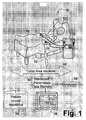
FIGURE 1 is a diagrammatic illustration of a patient monitoring system;FIGURE 2 is a diagrammatic illustration of a portion of the patient monitoring system;FIGURES 3-7 show Patient Indices displays;FIGURE 8 is a graphical representation of a blood pressure measurement and a medication drip rate; andFIGURE 9 is a set of ROC curves.- With reference to
FIGURE 1 , apatient monitoring system 10 analyzes physiological information over a period of time to determine the wellbeing of apatient 12, e.g. whether the patient's condition is improving, stabilizing, or deteriorating. Thepatient monitoring system 10 monitors wellbeing of the patients with various conditions such as postoperative recovery patient, emergency care unit patients, infants susceptible to sudden infant death syndrome, and others. Thebedside monitor 22 measurements are collected in very short intervals as some medical conditions require urgent intervention. Other data (clinical observations, lab tests, medication administration, imaging studies, etc) are collected in longer time intervals. - In the illustrated example, the
patient monitoring system 10 includes a wireless or wired patient point-of-care network which includes: (i)sensor nodes 20 disposed on thepatient 12 to monitor vital signs such as electrocardiographic (ECG) data, heart rate, respiratory rate, respiratory cycle, blood pressure, or so forth; and (ii) a bedside blood oxygen saturation (SpO2)monitor 22 connected with an SpO2 fmgertip probe 24. The wireless or wired point-of-care network is an example, and those skilled in the art can readily include additional or other medical devices such as high resolution sensors and bedside monitors and ventilators in the network. Moreover, the wireless point-of-care network can be changed on an ad hoc basis by adding or removing medical devices. - It will be appreciated that wires or cabling are not necessarily completely omitted from the wireless patient point-of-care network - for example, the SpO2 fingertip probe 24 may be connected with the SpO2 monitor 22 by a cable. Similarly, although not illustrated, it is contemplated that some of the devices of the patient point-of-care network may include power cords connected to house electricity. For example, although the illustrated, the SpO2
monitor 22 is battery-powered, it could instead or additionally include a power cord plugged into a conventional electrical power outlet. - The patient point-of-care network further includes a
patient identification device 40. In the illustrated embodiment, thepatient identification device 40 is disposed on a wristband worn by themedical patient 12; however, more generally thepatient identification device 40 can be worn or attached to thepatient 12 substantially anywhere. Themedical devices patient identification device 40 optionally also includes patient monitoring or therapy functionality, such as an ECG, SpO2, or other sensor. - The wireless data communication with a local area network 48 of the hospital or other medical facility is diagrammatically indicated in
FIGURE 1 by ajagged connector 52. The collected data is stored at a monitoredparameters data memory 50 and can be transferred to apatient record repository 54, displayed on a vital signs monitoring station or surveillance center ordisplay 56, compared with previous sensor readings, or otherwise utilized for patient monitoring and treatment evaluation. Indeed, once the collected data is sent to and stored in thepatient record repository 54, it can be used by any device on the network 48 which has the proper authorization to access it. For example, the collected data can be sent back to the bedside monitor 22 or vital signs monitoring station or surveillance center ordisplay 56 via the local area network 48. - A
physiological information analyzer 58 receives physiological information from one or more sensors, bedside patient monitors, and ventilators for short interval data, as well as longer interval relevant data from clinical observations, laboratory tests, medication administration records, and imaging studies, all of which are linked to the patient 12 to obtain and monitor physiological information. Theanalyzer 58 collects and processes the fused data to generate a visual representation such as a graph or a numerical value and/or an audio signal such as, for example, an alert or an alarm that a Patient Index has exceeded a critical limit. The medical professional takes notice of the alert or alarm and displayed clinical information and makes the decisions whether the intervention necessary, at what time, and to what extent. - With continuing reference to
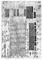
FIGURE 1 and further reference toFIGURE 2 , thephysiological information analyzer 58 continually calculates a severity of an illness of thepatient 12 for one or more Patient Indices (PI) that is expressed as composite acuity score(s). More specifically, abasic score generator 60 maps the detected measurement results along with the other information to a scoring system. E.g., a number of points is given to measurement values, clinical observations, patient condition, etc. The number of points, which is given to a particular measurement value and other categories, is predetermined in advance. Initially, the basic score is determined for the newly admitted patient. For example, a first value of each variable measured within an initial time period, such as a time from an initial contact with the patient at the intensive care unit to one hour after the patient arrival to the intensive care unit, is taken. Of course, the initial contact may happen in an emergency room, at home, at the ambulance, and the like. For example, Systolic Blood Pressure, which is measured greater than or equal to 200 mm Hg, is given a score of 2. If Systolic Blood Pressure is measured between 70 and 99 mm Hg, it is given a score of 5; if less than 70 mm Hg, it is given a score of 13, else, if between 100 and 199 mm Hg, the score is 0. In this manner, the certain measurement values and medical conditions of predefined categories are given a certain score, as, for example, outlined in the Table 1 below.Table 1 Record the number in square brackets if the condition is present: (1) Age in years: [0] <40 [7] 40-59 [12] 60-69 [15] 70-74 [16] 75-79 [18] >=80 (2) Heart Rate in beats per minute: [11] <40 [2] 40-69 [0] 70-119 [4] 120-159 [7] >=160 (3) Systolic blood pressure, mm Hg: [13] <70 [5] 70-99 [0] 100-199 [2] >=200 (4) Body Temperature in °C: [0] <39 [3] >=39 (5) If on ventilation or CPAP PaO2/FI02: [11] <100 [9] 100-199 [7] >=200 (6) Urinary Output in L per 24 hours: [11] <0.500 [4] 0.500-0.999 [0] >=1.000 (7) Serum Urea Nitrogen in mg/dL: [0] <28 [6] 28-83 [10] >=84 (8) WBC count in 1000 per µL: [12] <1.0 [0] 1.0-19.9 [3] >=20 (9) Serum Potassium in mEq/L: [3] <3.0 [0] 3.0-4.9 [3] >=5.0 (10) Serum Sodium in mEq/L: [5] <125 [0] 125-144 [1] >=145 (11) Serum Bicarbonate in mEq/L: [6] <15 [3] 15-19 [0] >=20 (12) Bilirubin Level in mg/dL: [0] <4.0 [4] 4.0-5.9 [9] >=6.0 (13) Glasgow Coma Score: [26] <6 [13] 6-8 [7] 9-10 [5] 11-13 [0] 14-15 (14) Chronic Diseases: [9] Metastatic Carcinoma [10] Hematologic Malignancy [17]AIDS (15) Type of Admission: [0] Scheduled Surgery [6] Medical [8] Unscheduled Surgery patient 12. - A composite acuity score generator or processor or means 70 automatically determines one or more real time composite acuity score(s) by receiving at least the updated basic acuity score(s) from the
basic score generator 60, an updated variability metric from the variabilitymetric generator 62, medication information from a medication administration processor or means 72, patient data from apatient profile 74, physician's notes and nurse's notes from a clinical notes andorders entry journal 76, laboratory test results from lab results 78, imaging results fromimaging studies 80, and other like data. - As described above, the
physiological information analyzer 58 continually calculates a severity of an illness of thepatient 12 for one or more Patient Indices (PI) that is expressed as composite acuity score(s). - With reference to
FIGURES 3 and4 , ahome screen 88 of the patient display is shown. A patient indices selection row orboxes 90 includes an exemplary list of the patient acuity indices (PI). Example of one such PI is a real-time extension to the clinically accepted SAPS-II (Simplified Acute Physiology Score) 92, a score which correlates with a patient's mortality rate in the ICU. The real-time extension of SAPS-II conveniently provides for the initial calculation of the SAPS-II score as well as a continuously updated SAPS-II score that is capable of detecting and showing patient deterioration. Another example of PI is MOD (Multi-Organ Dysfunction Score) 94, a score which correlates with the likelihood of multi-organ failure in the ICU. Another example is PIN (Physiological Instability Numeric) 96, a uniquely defined feature vector score that correlates with the current physiological instability of the patient in the ICU.Icons 98,..., 100 labeled "PI-4", through "PI-N" may be any currently accepted or future Patient Indices. - By clicking on any of the icons in the
patient indices row 90, the corresponding patient index information is displayed. InFIGURE 3 , the real time SAPS-II index is currently selected, as the icon "SAPS-II" is highlighted. - With continuing reference to
FIGURE 3 , thehome screen 88 includes a linear scaledgraphic window 110 showing a patient index trend or SAPS-II score curve 112 over time. The latest (or current) time tL for thepatient index curve 112 is placed at a point close to the right end of thewindow 110 and marked with a vertical cursor ormechanism 114. The time scale can be controlled through "Time Scale"control icons 120 at the bottom row. The time scale controls include:Linear scale 122,Log scale 124, Left (<-) and Right (->) cursor controls 126, 128, which allow the user to transverse or move through the trend data to see how the Vitals and PI Scores have changed over time. Likewise, the user may jump to a specific time in the trend by placing the cursor over that area and left-clicking the mouse. The standard or default window is a 24-hour window in the Linear scale with current time at the right. Atime label 130 is marked backward from the current time to allow thewindow 110 to cover 24-hour data prior to the current time. Adate label 132, shown beneath the time label, indicates which portion of thewindow 110 belongs to which date. By clicking on "Zoom In", "Zoom Out"icons window 110. - The composite acuity score or patient index or overall SAPS-II score value at the current time tL is displayed in a SAPS-
II score window 140 at the right side of thescreen 88. Individual parameters' scores and vital values contributing to the overall SAPS-II score are displayed invital item boxes 142. For example, the parameters include arterial blood pressure (ABP), Glasgow coma score (GCS), and blood urea nitrogen (BUN), and others for calculation of the SAPS-II score value. The default position of thevertical cursor 114 is at the current time tL, thus the current SAPS-II score and its details are shown in the real-time manner. Thecursor 114 can be moved to any position of thewindow 110 and the SAPS-II score and its details at that time point are correspondingly displayed along with the date and time. - By clicking the "Table List"
button 150 at the right bottom corner of thescreen 88, all SAPS-II scores and individual variable values and scores can be displayed in a table with time and date. - An
adjustable threshold level 152 in thegraphic window 110 within the SAPS-II score curve 112 sets an allowable value for the SAPS II score. When the SAPS-II score exceeds the threshold, an alerting message can be issued on thescreen 88, as seen in a "Alert"message box 154. - With reference again to
FIGURE 4 , clicking the "Log"icon 124 in the "Time Scale"control row 120, a SAPS-II log scaledgraphic window 160 using a log scale with 10 as the base is displayed. The loggraphic window 160 is functionally similar to the lineargraphic window 110, except that the time scale in the loggraphic window 160 is in a logarithmic scale. For thetime label 130, the starting time is the current time, e.g. 17:00:00, at the right end of thelog window 160. The time is backward labeled in hours in the log scale. The numbers that show time are negative as referring to the past time. In thedate label 132, the starting date is the current day, e.g. 03/14/05, as shown in the right end of the window. The date is backward labeled in days in the log scale. The numbers that show date are negative as referring to the past date. In the log time scale, the data can be viewed in a very large time scope, with emphasis and more detail in recent data and less detail in long-before data. The SAPS-II score value and its contributing individual variables' scores and values at the position of thevertical cursor 114 are displayed in the right part of thescreen 88. Thecursor 114 can be moved to any place in thewindow 160 where the data are available and the corresponding SAPS-II score and its detailed contributions are shown accordingly. - With reference to
FIGURE 5 , by clicking within the overall SAPS-II score window 140, the detailed individual components of the SAPS-II patient index are displayed along with the overall SAPS Score and SAPS Probability of Mortality. A reduced SAPS-II Scoregraphic window 110 is shown in atop panel 170 of the screen. As discussed above, the graphic window includes TimeScale control icons 120 and the position of thevertical cursor 114 as previously chosen. All SAPS-II individual components are displayed for the time indicated by the cursor position in a lower panel ordetailed component display 172 of thescreen 88. All pre-established and set SAPS-II thresholds as well as the individual component "Vitals" and "SAPS" scores and graphical indicators are shown for each component. Other non-varying components such as Age, Type of Admission and Chronic Diseases are shown for entry and display purposes. The individual component SAPS scores as well as the Overall SAPS Score and SAPS Probability are all automatically calculated and displayed for the selected position of thevertical cursor 114. Thevertical cursor 114 can be moved in each window as previously described. - The "Table List" control icon is replaced with a "PI Home" control icon, which returns the user to the "Patient Indices Home" display.
- With reference to
FIGURES 6 and7 , by clicking any of thevital item boxes 142 on thescreen 88, e.g. such as BUN-box, detailed trends information about the particular variable can be displayed along with the overall SAPS-II trend and score.FIGURE 6 shows a linear scale, whileFIGURE 7 shows a log scale. Thetop panel 170 is the overall SAPS-II trend window and a SAPS-II score value at the cursor point. Middle and lower panels or trend displays 180, 182 show the BUN's individual SAPS score and BUN value in the time window corresponding to the overall SAPS-II score window. The BUN SAPS score and BUN value at the cursor time point are shown in the right side of the screen. - The "Time Scale"
control icons 120 are available. The "Table List" control icon is replaced with a "PI Home" control icon, which returns the user to the "Patient Indices Home" display. - The vertical cursors can be moved in each window as previously described. The Vital values and SAPS score at the cursors' positions are accordingly displayed.
- With reference to
FIGURE 8 , the patient's condition is stable for a period of time until there is an increase in blood pressure for a short period of time. Increase in the blood pressure is followed by a precipitous drop in blood pressure. Such drop in the patient's blood pressure might be indicative of the beginning of the hemodynamic instability of thepatent 12. This point in time can serve as a fiducial point at which the condition of the patient 12 starts worsening. After clinical observation, the drip rate of the medication is increased which is calculated to correct the patient's deterioration. This condition and others would automatically alert medical professionals to take notice of the displayed information of this clinically significant change, and make decisions whether the intervention is necessary, at what time, and to what extent. - The continually updated composite score(s) indicate the wellbeing of the
patient 12 and predicts when the worsening physiological trend would reach the point indicating that intervention is necessary to alter the patient outcome in a positive way. - With reference to
FIGURE 9 , the ROC curves are shown. As known in the art, the ROC curves represent a tradeoff between the sensitivity and specificity. The dotted curves use the first thirteen SAPS II features of the Table 1 and show that sensitivity and specificity, of need for intervention, improve as time moves closer to actual intervention. This shows that there is value in continuously updating the SAPS II score. - The solid curves use the same thirteen SAPS II features, as used in the dotted curves and, in addition, Hematocrit, which is one of the features of the APACHE algorithm. As shown, by adding one additional feature, a considerable improvement is made toward being able to show the need for intervention. By supplementing the continually updated basic acuity scores with additional measurements and parameters such as heart rate variability (HRV), anion gap, estimated cardiac output, blood lactic acid, A-a gradient, and other readily available clinical and physiological measurement values, single-organ system failure, multi-organ system failure, physiological instability as well as other serious conditions of the patient 12 are detected in earlier stages. Each of the above listed early warning signals individually is not typically a reliable predictor of the patient deterioration, but when taken collectively as a 'feature vector'; the early warning signals they can become an extremely reliable predictor. The improved sensitivity and specificity of shown ROC curves over the SAPS-II individual performance shows this reliability.
- With reference again to
FIGURE 2 , in one embodiment, a keydeteriorating values extractor 200 extracts key deteriorating values. Information pertinent to the key parameters that cause deterioration is displayed on thedisplay 56. For example, pulse irregularities can cause an ECG signal to be displayed. The keydeteriorating values extractor 200 additionally performs continuous analysis of the trend data searching for unexpected clinically significant changes. Clinically unexpected significant changes as well as the lack of expected physiological change to drugs are examples of the key extracted features. Such analysis and display of the information provides a strategic decision support. The medical personnel can make enhanced strategic plans for the wellbeing of the patient 12 with anticipation to positively alter patient's outcome which, for example, includes death, discharge to home, and discharge to other care units/settings. - An
alarm generator 210 generates an alarm or alert. For example, if one of the monitored individual parameter values exceeds a corresponding threshold value an alert might be issued. As another example, if the composite acuity score exceeds a corresponding thresho ld value, the alarm generator generates the alarm which is provided to the medical personnel. The alarm might be set as a tone, a voice signal, or a display of a textual message on thedisplay 56. If the alarm caused by an individual parameter value, the medical personnel can address the respective physiological function that caused the alarm. For example, if the heart rate is too low or if blood pressure is too low and dropping, the medical personnel takes the appropriate steps which typaically lead to increasing the heart rate and/or blood pressure. Alarms of different levels, such as a caution or watch level, a critical level, an immediate intervention level, and the like can be generated as different thresholds or combinations of thresholds, or composite thresholds are reached or exceeded. - If the alarm is caused by the composite acuity score, such alarm indicates to the medical personnel that the patient is deteriorating in some way. The medical personnel determines the necessity, time and nature of therapeutic intervention. Examples of major therapeutic interventions are the use of intra-aortic balloon pumps, vaso-active medications, large fluid boluses, and significant blood transfusions.
- In one embodiment, the data provided by the
monitoring system 10 is analyzed to retrospectively determine how the medical personnel reacted to certain acuity scores and how the interventions affected the patient outcome. The administrator can evaluate how well the medical personnel managed hemodynamic instability of the patient, transient instability of the patient, and so forth. By looking at the change in the acuity scores, the administrator can modify the unit performance and interventional procedures to enhance the wellbeing of the patient. - The invention has been described with reference to the preferred embodiments. Modifications and alterations will occur to others upon a reading and understanding of the preceding detailed description. It is intended that the invention be construed as including all such modifications and alterations insofar as they come within the scope of the appended claims or the equivalents thereof.
Claims (15)
- A patient monitoring system(10) comprising:at least one sensor(20, 24) which senses shorter interval physiological parameters of a monitored patient(12);at least one database(72, 74, 76, 78, 80) which stores longer interval data of the monitored patient(12);a composite acuity score generator(70) which generates or updates one or more composite acuity scores indicative of wellbeing of the patient(12) based at least on the sensed physiological parameters and the longer interval data;a monitor(22, 56) for displaying at least current values of at least one of selected sensed physiological parameters values, longer interval data, and the composite acuity score; andan alarm generator(210) which generates an alarm in response to the current composite acuity reaching a threshold,characterized in that said patient monitoring system(10) further comprises a key deteriorating parameter extractor(200) which determines the physiological parameters primarily responsible for the composite acuity score reaching the threshold, the key deteriorating parameters being displayed on the monitor(22, 56).
- The system as set forth in claim 1, further including:
a basic acuity score generator(60) which maps values of at least the sensed physiological parameters to points which are preassigned to each sensed physiological parameter to generate basic acuity scores of the patient(12). - The system as set forth in claim 2, wherein the basic acuity score generator (60) continually automatically updates the basic acuity scores based on the sensed physiological parameters.
- The system as set forth in claim 1, wherein the monitor(22, 56) includes:a Patient Indices Interactive Display(88) including:a Patient Index Score Window(140) which displays the composite acuity score of the patient(12), the displayed composite acuity score being indicative of an overall current condition of the patient, anda Patient Index Trend Curve(112) which displays the trend data in a graphic window(110, 160) including a map showing how the patient reached the current condition.
- The system as set forth in claim 4, further including:a mechanism(114) for selecting a time(tL) which selection triggers an automatic display in vital boxes(142) of selected physiological parameters and the longer interval data which contribute to the composite acuity score at the selected time(tL).
- The system as set forth in claim 5, further including:a detailed component display(172) which displays detailed values of the selected physiological parameters and the longer interval data for the displayed composite acuity score for the selected time(tL).
- The system as set forth in claim 5, further including:trend displays(180, 182) which display trend data curves for the selected physiological parameters and the longer interval data which contribute to the composite acuity score.
- The system as set forth in claim 1, further including:a key deteriorating parameter extractor(200) which causes the monitor(22, 56) to display the physiological parameters that are significant to medical personnel deciding a course of action for altering and enhancing the patient's current physiological condition.
- A monitoring method comprising:sensing shorter interval physiological parameters of a monitored patient;collecting longer interval data of the patient;generating one or more composite acuity scores indicative of wellbeing of the patient based at least on the sensed physiological parameters and the longer interval data;displaying at least current values of at least one of selected sensed physiological parameters values, the longer interval data, and the composite acuity score; andgenerating an alarm in response to the composite acuity score reaching a threshold value which is indicative of a medically significant deterioration of the condition of the patient,characterized in that said method further comprises extracting key physiological parameters values conducive to the overall deteriorating condition of the patient; anddisplaying the key deteriorating parameters values.
- The method as set forth in claim 9, further including:generating basic acuity score values including:preassigning points to at least each sensed physiological parameter, andmapping values of the sensed physiological parameter to the preassigned points; andcontinually automatically updating the basic acuity score based at least on the sensed physiological parameters.
- The method as set forth in claim 9, wherein the step of displaying includes:displaying the composite acuity score of the patient(12), the composite acuity score being indicative of an overall current condition of the patient; anddisplaying the trend data in a graphic window(110, 160) including a map showing how the patient reached the current condition.
- The method as set forth in claim 11, further including:selecting a time(tL); anddisplaying the physiological parameters and the longer interval data which contribute to the composite acuity score at the selected time(tL).
- The method as set forth in claim 12, further including:displaying detailed values of the physiological parameters and the longer interval data for the displayed composite acuity score for the selected time(tL).
- The method as set forth in claim 12, wherein the step of displaying includes:selecting physiological parameters and the longer interval data which contribute to the displayed composite acuity score; anddisplaying trend data for the selected physiological parameters and the longer interval data.
- The method as set forth in claim 9, further including:based on the displayed key deteriorating parameters values, determining a course of treatment.
Applications Claiming Priority (2)
| Application Number | Priority Date | Filing Date | Title |
|---|---|---|---|
| US69275405P | 2005-06-22 | 2005-06-22 | |
| PCT/IB2006/051888WO2006136972A1 (en) | 2005-06-22 | 2006-06-13 | An apparatus to measure the instantaneous patients' acuity value |
Publications (2)
| Publication Number | Publication Date |
|---|---|
| EP1903932A1 EP1903932A1 (en) | 2008-04-02 |
| EP1903932B1true EP1903932B1 (en) | 2010-12-22 |
Family
ID=37103185
Family Applications (1)
| Application Number | Title | Priority Date | Filing Date |
|---|---|---|---|
| EP06765731AActiveEP1903932B1 (en) | 2005-06-22 | 2006-06-13 | An apparatus to measure the instantaneous patients' acuity value |
Country Status (7)
| Country | Link |
|---|---|
| US (1) | US9167968B2 (en) |
| EP (1) | EP1903932B1 (en) |
| JP (1) | JP5584413B2 (en) |
| CN (1) | CN101203172B (en) |
| AT (1) | ATE492208T1 (en) |
| DE (1) | DE602006019095D1 (en) |
| WO (1) | WO2006136972A1 (en) |
Families Citing this family (82)
| Publication number | Priority date | Publication date | Assignee | Title |
|---|---|---|---|---|
| US20130268296A1 (en)* | 2003-05-06 | 2013-10-10 | M-3 Information Llc | Method and apparatus for identifying, monitoring and treating medical signs and symptoms |
| WO2007072364A2 (en)* | 2005-12-19 | 2007-06-28 | Koninklijke Philips Electronics, N.V. | Hierarchical real-time patient state indices for patient monitoring |
| WO2007142968A2 (en) | 2006-05-30 | 2007-12-13 | The University Of North Carolina At Chapel Hill | Methods, systems, and computer program products for evaluating a patient in a pediatric intensive care unit |
| US8550996B2 (en)* | 2007-07-27 | 2013-10-08 | The Hospital For Sick Children | Medical vital sign indication tool, system and method |
| US20090093686A1 (en)* | 2007-10-08 | 2009-04-09 | Xiao Hu | Multi Automated Severity Scoring |
| US8706516B2 (en)* | 2008-01-11 | 2014-04-22 | General Electric Company | System and method to manage a workflow in delivering healthcare |
| CN101938939B (en)* | 2008-02-07 | 2014-11-26 | 皇家飞利浦电子股份有限公司 | Device for measuring and predicting respiratory stability of a patient |
| US8510126B2 (en)* | 2008-02-24 | 2013-08-13 | The Regents Of The University Of California | Patient monitoring |
| US20100017755A1 (en)* | 2008-07-15 | 2010-01-21 | Rasmussen G Lynn | Systems and methods for graphically conveying patient medical information |
| US20110298806A1 (en)* | 2008-07-15 | 2011-12-08 | Rasmussen G Lynn | Systems and methods for graphically conveying information |
| WO2010046820A1 (en)* | 2008-10-22 | 2010-04-29 | Koninklijke Philips Electronics N.V. | Performing measurement of a subject |
| TWI397020B (en)* | 2008-10-24 | 2013-05-21 | Inst Information Industry | Method and system for risk level evaluation of patients |
| CN101862181B (en)* | 2009-04-15 | 2013-03-20 | 深圳迈瑞生物医疗电子股份有限公司 | Device for monitoring conditions of patients |
| EP2440117B1 (en)* | 2009-06-12 | 2013-05-29 | Koninklijke Philips Electronics N.V. | A medical device having a reminder function |
| CN102458240B (en)* | 2009-06-18 | 2014-10-29 | 皇家飞利浦电子股份有限公司 | Ecg monitoring with reduced false asystole alarms |
| DE102009035250B4 (en)* | 2009-07-29 | 2019-06-13 | Meierhofer Medizintechnik Gmbh | Method and system for monitoring the medical condition of a patient |
| JP5243375B2 (en)* | 2009-09-09 | 2013-07-24 | 日本光電工業株式会社 | Biological signal processing device and medical device control method |
| US8525680B2 (en)* | 2009-09-18 | 2013-09-03 | Hill-Rom Services, Inc. | Apparatuses for supporting and monitoring a condition of a person |
| US8498881B2 (en)* | 2009-10-20 | 2013-07-30 | Universal Research Solutions, Llc | Generation and data management of a medical study using instruments in an integrated media and medical system |
| US20120239434A1 (en)* | 2009-12-11 | 2012-09-20 | Koninklijke Philips Electronics N.V. | System and method for generating graphical representation of patient status |
| WO2011073815A2 (en)* | 2009-12-19 | 2011-06-23 | Koninklijke Philips Electronics N.V. | Copd exacerbation prediction system and method |
| EP2517131A2 (en)* | 2009-12-21 | 2012-10-31 | Koninklijke Philips Electronics N.V. | Bode index measurement |
| WO2011116340A2 (en)* | 2010-03-18 | 2011-09-22 | Oregon Health & Science University | Context-management framework for telemedicine |
| WO2012023931A1 (en)* | 2010-08-17 | 2012-02-23 | Welch Allyn, Inc. | User installed applications in a physiological parameter display device |
| US12198790B1 (en) | 2010-10-07 | 2025-01-14 | Masimo Corporation | Physiological monitor sensor systems and methods |
| RU2630122C2 (en)* | 2010-11-08 | 2017-09-05 | Конинклейке Филипс Электроникс Н.В. | Method for continuous forecasting of disease severity, death and hospitalization duration |
| JP5923519B2 (en)* | 2010-12-22 | 2016-05-24 | コーニンクレッカ フィリップス エヌ ヴェKoninklijke Philips N.V. | System and method for providing medical care provider and device management for patient care |
| CN102622501B (en)* | 2011-01-30 | 2017-06-09 | 深圳迈瑞生物医疗电子股份有限公司 | Hemodynamic parameter management method, system and custodial care facility |
| CN103402423B (en)* | 2011-03-01 | 2016-09-21 | 皇家飞利浦有限公司 | Patient deterioration detection |
| JP6067008B2 (en)* | 2011-06-30 | 2017-01-25 | ユニヴァーシティ オヴ ピッツバーグ オヴ ザ コモンウェルス システム オヴ ハイアー エデュケーション | System and method for determining susceptibility to cardiopulmonary dysfunction |
| WO2013017972A2 (en) | 2011-07-29 | 2013-02-07 | Koninklijke Philips Electronics N.V. | Graphical presentation of ews/patient state |
| WO2013093692A2 (en)* | 2011-12-21 | 2013-06-27 | Koninklijke Philips Electronics N.V. | Method and system to predict physiologic and clinical status changes |
| RU2629799C2 (en)* | 2012-02-17 | 2017-09-04 | Конинклейке Филипс Н.В. | Evaluation and observation of acute lung injury (ali) / acute respiratory distress syndrome (ards) |
| US9433348B2 (en) | 2012-05-18 | 2016-09-06 | Koninklijke Philips N.V. | Method of rendering hemodynamic instability index indicator information |
| CN102743157B (en)* | 2012-07-14 | 2015-01-14 | 深圳邦健生物医疗设备股份有限公司 | Monitor and method for displaying long time physiological parameter data |
| RU2685681C2 (en)* | 2012-12-03 | 2019-04-22 | Конинклейке Филипс Н.В. | System and method for optimizing frequency of data collection and thresholds for deterioration detection algorithm |
| US20140195266A1 (en)* | 2013-01-09 | 2014-07-10 | Nuance Communications, Inc. | Techniques to improve accuracy of a medical report relating to medical imaging study |
| US20140195267A1 (en)* | 2013-01-09 | 2014-07-10 | Nuance Communications, Inc. | Techniques to improve accuracy of a medical report relating to a medical imaging study |
| JP2014194712A (en)* | 2013-03-29 | 2014-10-09 | Fujifilm Corp | Inspection data display control device, method and program |
| CN104274158A (en)* | 2013-07-10 | 2015-01-14 | 上海宽带技术及应用工程研究中心 | Furniture physical sign detection device and furniture type physical sign monitoring system |
| CN104274181B (en)* | 2013-07-10 | 2018-12-18 | 上海宽带技术及应用工程研究中心 | Furniture type sign detection method, system and monitoring system |
| FR3009491B1 (en) | 2013-08-07 | 2015-09-04 | Assist Publ Hopitaux De Paris | INTEGRATED SOLUTION FOR MONITORING AND REAL-TIME MONITORING OF THE PATHOLOGICAL STATUS OF A CEREBRO-LESE PATIENT |
| US20150100327A1 (en)* | 2013-10-04 | 2015-04-09 | Cerner Innovation, Inc. | Maintaining context between applications utilizing a prioritized patient list |
| AU2015223182B2 (en) | 2014-02-25 | 2017-09-14 | Icu Medical, Inc. | Patient monitoring system with gatekeeper signal |
| WO2015136502A1 (en)* | 2014-03-13 | 2015-09-17 | Koninklijke Philips N.V. | Patient watch-dog and intervention/event timeline |
| EP3174461A4 (en)* | 2014-08-01 | 2018-04-04 | Edwards Lifesciences Corporation | Measurement of a patient analyte using wavelet transform analysis |
| US9940214B2 (en) | 2014-08-29 | 2018-04-10 | Cisco Technology, Inc. | Index filter for visual monitoring |
| EP3892198B1 (en) | 2014-11-14 | 2024-03-06 | ZOLL Medical Corporation | Medical premonitory event estimation |
| US10485486B2 (en)* | 2014-11-18 | 2019-11-26 | Baylor College Of Medicine | Clinical metric for predicting onset of cardiorespiratory deterioration in patients |
| US9615784B2 (en) | 2014-12-15 | 2017-04-11 | General Electric Company | Tactical clinical evaluation of patient monitor events |
| US10867703B2 (en) | 2015-02-26 | 2020-12-15 | Conduent Business Services, Llc | System and method for predicting health condition of a patient |
| JP6015882B1 (en)* | 2015-03-26 | 2016-10-26 | コニカミノルタ株式会社 | Terminal device and terminal processing method of monitored person monitoring system, central processing unit and central processing method of monitored person monitoring system, and monitored person monitoring system |
| CN107949317B (en)* | 2015-10-12 | 2021-07-27 | 深圳迈瑞生物医疗电子股份有限公司 | Method and system for dynamically displaying change of interval measurement parameters and monitor |
| WO2017070120A1 (en) | 2015-10-19 | 2017-04-27 | Icu Medical, Inc. | Hemodynamic monitoring system with detachable display unit |
| WO2017191227A1 (en)* | 2016-05-04 | 2017-11-09 | Koninklijke Philips N.V. | Estimation and use of clinician assessment of patient acuity |
| EP3547320A4 (en)* | 2016-05-20 | 2020-11-11 | Pulse Participações S.A. | Related systems and method for correlating medical data and diagnostic and health treatment follow-up conditions of patients monitored in real-time |
| US10842701B2 (en) | 2016-10-14 | 2020-11-24 | Stryker Corporation | Patient support apparatus with stabilization |
| US10339911B2 (en) | 2016-11-01 | 2019-07-02 | Stryker Corporation | Person support apparatuses with noise cancellation |
| CA3042686A1 (en)* | 2016-11-02 | 2018-05-11 | Respiratory Motion, Inc. | Respiratory early warning scoring systems and methods |
| US10573155B2 (en)* | 2017-12-07 | 2020-02-25 | Covidien Lp | Closed loop alarm management |
| WO2020011778A1 (en)* | 2018-07-09 | 2020-01-16 | Koninklijke Philips N.V. | Reducing redundant alarms |
| JP7240155B2 (en)* | 2018-12-06 | 2023-03-15 | 日本光電工業株式会社 | Condition change determination method, condition change determination device, program and computer readable medium used for the device or method |
| WO2020133430A1 (en)* | 2018-12-29 | 2020-07-02 | 深圳迈瑞生物医疗电子股份有限公司 | Monitoring method and device based on physiological parameters, and computer storage medium |
| US10762990B1 (en)* | 2019-02-01 | 2020-09-01 | Vignet Incorporated | Systems and methods for identifying markers using a reconfigurable system |
| US11925474B2 (en)* | 2019-08-22 | 2024-03-12 | Koninklijke Philips N.V. | Methods and systems for patient baseline estimation |
| CN114586107A (en)* | 2019-10-15 | 2022-06-03 | 索尼集团公司 | Information processing apparatus, information processing method, and program |
| CN110840425B (en)* | 2019-11-20 | 2022-05-13 | 首都医科大学宣武医院 | Health monitoring system and method for emergency patients in treatment |
| DE102019008406B4 (en) | 2019-12-04 | 2024-02-01 | Drägerwerk AG & Co. KGaA | Arrangement and method for displaying medical alarms |
| LU101515B1 (en)* | 2019-12-06 | 2021-06-08 | Draegerwerk Ag & Co Kgaa | Arrangement and method for displaying medical alarms |
| TWI709978B (en) | 2019-12-20 | 2020-11-11 | 國泰醫療財團法人國泰綜合醫院 | Smart medical decision method and smart medical decision system |
| CN115836360A (en)* | 2020-04-10 | 2023-03-21 | 皇家飞利浦有限公司 | Diagnostically-adaptive acute patient monitoring |
| EP4139927A4 (en)* | 2020-04-20 | 2024-06-12 | Quantaira Inc. | SYSTEM AND METHOD FOR REMOTE MONITORING OF AN ICU ENVIRONMENT |
| US11195616B1 (en)* | 2020-10-15 | 2021-12-07 | Stasis Labs, Inc. | Systems and methods using ensemble machine learning techniques for future event detection |
| EP4068305A1 (en)* | 2021-03-31 | 2022-10-05 | Riatlas S.r.l. | Method for displaying on a screen of a computerized apparatus a temporal trend of a state of health of a patient and computerized apparatus |
| IT202100028643A1 (en)* | 2021-11-11 | 2023-05-11 | Riatlas S R L | Method of changing a display on a computerized apparatus screen of a health condition of a patient and computerized apparatus |
| US20230075176A1 (en)* | 2021-09-08 | 2023-03-09 | Optum Services (Ireland) Limited | Interactable and interpretable temporal disease risk profiles |
| JP7725317B2 (en)* | 2021-09-28 | 2025-08-19 | 富士フイルム株式会社 | Information processing device, information processing method, and information processing program |
| US12326918B2 (en)* | 2021-10-18 | 2025-06-10 | Optum Services (Ireland) Limited | Cross-temporal encoding machine learning models |
| US12327193B2 (en) | 2021-10-19 | 2025-06-10 | Optum Services (Ireland) Limited | Methods, apparatuses and computer program products for predicting measurement device performance |
| PE20250485A1 (en)* | 2021-12-28 | 2025-02-21 | Univ Peruana De Ciencias Aplicadas S A C | Electronic equipment for estimating hospitalization time for patients diagnosed with respiratory disease |
| EP4500547A1 (en)* | 2022-03-30 | 2025-02-05 | Lonhea SA | System for processing health indicator values of a patient |
| US12229188B2 (en) | 2022-05-17 | 2025-02-18 | Optum Services (Ireland) Limited | Machine learning techniques for generating disease prediction utilizing cross-temporal semi-structured input data |
Family Cites Families (34)
| Publication number | Priority date | Publication date | Assignee | Title |
|---|---|---|---|---|
| US5331549A (en)* | 1992-07-30 | 1994-07-19 | Crawford Jr John M | Medical monitor system |
| CA2142906A1 (en)* | 1992-08-21 | 1994-03-03 | Peter L. Brill | Method and apparatus for measuring psychotherapy outcomes |
| US6067467A (en)* | 1994-02-07 | 2000-05-23 | New York University | EEG operative and post-operative patient monitoring method |
| EP0707824A2 (en) | 1994-10-20 | 1996-04-24 | Hewlett-Packard Company | Telemetry docking station |
| IL118389A0 (en)* | 1996-05-22 | 1996-09-12 | Gat Yigal | Fetal monitoring system and method |
| US5792047A (en)* | 1997-01-15 | 1998-08-11 | Coggins; George | Physiological parameter monitoring and bio-feedback apparatus |
| WO1999027482A1 (en)* | 1997-11-20 | 1999-06-03 | Beth Israel Deaconess Medical Center | Neonatal illness severity/mortality computerized determination system & method |
| US6338713B1 (en)* | 1998-08-18 | 2002-01-15 | Aspect Medical Systems, Inc. | System and method for facilitating clinical decision making |
| US6821249B2 (en)* | 1999-03-08 | 2004-11-23 | Board Of Regents, The University Of Texas | Temperature monitoring of congestive heart failure patients as an indicator of worsening condition |
| US7593952B2 (en)* | 1999-04-09 | 2009-09-22 | Soll Andrew H | Enhanced medical treatment system |
| US6312378B1 (en) | 1999-06-03 | 2001-11-06 | Cardiac Intelligence Corporation | System and method for automated collection and analysis of patient information retrieved from an implantable medical device for remote patient care |
| US7475019B2 (en)* | 1999-11-18 | 2009-01-06 | Visicu, Inc. | System and method for physician note creation and management |
| JP3682617B2 (en)* | 1999-11-08 | 2005-08-10 | 日本光電工業株式会社 | Vertical split display method for multiple patient data |
| US6440066B1 (en)* | 1999-11-16 | 2002-08-27 | Cardiac Intelligence Corporation | Automated collection and analysis patient care system and method for ordering and prioritizing multiple health disorders to identify an index disorder |
| US6317700B1 (en)* | 1999-12-22 | 2001-11-13 | Curtis A. Bagne | Computational method and system to perform empirical induction |
| US7668661B2 (en)* | 2000-04-28 | 2010-02-23 | Siemens Healthcare Diagnostics Inc. | Liver disease-related methods and systems |
| IL139387A0 (en)* | 2000-11-01 | 2001-11-25 | Dintex Ltd | Feedback system and method for monitoring and measuring physical exercise related information |
| JP4189787B2 (en)* | 2001-03-06 | 2008-12-03 | 日本光電工業株式会社 | Biological information display monitor and system |
| AU2002309987A1 (en)* | 2001-05-25 | 2002-12-09 | Hill-Rom Services, Inc. | Modular patient room |
| GB0113212D0 (en)* | 2001-05-31 | 2001-07-25 | Oxford Biosignals Ltd | Patient condition display |
| ATE410953T1 (en)* | 2001-06-13 | 2008-10-15 | Compumedics Ltd | METHOD FOR MONITORING CONSCIOUSNESS |
| WO2003071391A2 (en)* | 2002-02-19 | 2003-08-28 | Lexicor Medical Technology, Inc. | Systems and methods for managing biological data and providing data interpretation tools |
| US7468032B2 (en)* | 2002-12-18 | 2008-12-23 | Cardiac Pacemakers, Inc. | Advanced patient management for identifying, displaying and assisting with correlating health-related data |
| GB2389290B (en)* | 2002-05-31 | 2005-11-23 | Qinetiq Ltd | Data analysis system |
| US7074194B2 (en)* | 2003-05-19 | 2006-07-11 | Ischemia Technologies, Inc. | Apparatus and method for risk stratification of patients with chest pain of suspected cardiac origin |
| CA2470027A1 (en)* | 2003-06-05 | 2004-12-05 | Kingston General Hospital | Management systems and methods |
| US20040249299A1 (en)* | 2003-06-06 | 2004-12-09 | Cobb Jeffrey Lane | Methods and systems for analysis of physiological signals |
| WO2005006969A1 (en)* | 2003-07-16 | 2005-01-27 | Koninklijke Philips Electronics N.V. | A device and a computerized method arranged to enable a health-related coaching of an individual |
| US8639520B2 (en)* | 2003-10-06 | 2014-01-28 | Cerner Innovations, Inc. | System and method for creating a visualization indicating relationships and relevance to an entity |
| AU2005207002B2 (en) | 2004-01-21 | 2011-03-17 | University Of Utah Research Foundation | Mutant sodium channel Nav1.7 and methods related thereto |
| US20050240438A1 (en)* | 2004-04-22 | 2005-10-27 | Aaron Day | Method and system for improving health status of members of an entity |
| US7565194B2 (en)* | 2004-05-12 | 2009-07-21 | Zoll Medical Corporation | ECG rhythm advisory method |
| WO2005112749A1 (en)* | 2004-05-12 | 2005-12-01 | Zoll Medical Corporation | Ecg rhythm advisory method |
| CA2620302A1 (en)* | 2005-03-02 | 2006-09-08 | Spacelabs Healthcare, Llc | Trending display of patient wellness |
- 2006
- 2006-06-13CNCN2006800225371Apatent/CN101203172B/enactiveActive
- 2006-06-13USUS11/917,767patent/US9167968B2/enactiveActive
- 2006-06-13WOPCT/IB2006/051888patent/WO2006136972A1/enactiveApplication Filing
- 2006-06-13EPEP06765731Apatent/EP1903932B1/enactiveActive
- 2006-06-13DEDE602006019095Tpatent/DE602006019095D1/enactiveActive
- 2006-06-13JPJP2008517642Apatent/JP5584413B2/enactiveActive
- 2006-06-13ATAT06765731Tpatent/ATE492208T1/ennot_activeIP Right Cessation
Also Published As
| Publication number | Publication date |
|---|---|
| CN101203172A (en) | 2008-06-18 |
| JP5584413B2 (en) | 2014-09-03 |
| WO2006136972A1 (en) | 2006-12-28 |
| DE602006019095D1 (en) | 2011-02-03 |
| CN101203172B (en) | 2012-11-14 |
| JP2008543478A (en) | 2008-12-04 |
| EP1903932A1 (en) | 2008-04-02 |
| ATE492208T1 (en) | 2011-01-15 |
| US20080214904A1 (en) | 2008-09-04 |
| US9167968B2 (en) | 2015-10-27 |
Similar Documents
| Publication | Publication Date | Title |
|---|---|---|
| EP1903932B1 (en) | An apparatus to measure the instantaneous patients' acuity value | |
| US12263018B2 (en) | Spot check measurement system | |
| US8874379B2 (en) | Central station integration of patient data | |
| US10095838B2 (en) | Graphical presentation of EWS/patient state | |
| CN104838382B (en) | For optimizing method, system, medium and the monitoring station of data collection frequencies | |
| RU2630122C2 (en) | Method for continuous forecasting of disease severity, death and hospitalization duration | |
| US20160350488A1 (en) | Device, system and method for visualization of patient-related data | |
| JP6692355B2 (en) | A method for score confidence interval estimation when vital sign sampling frequency is limited | |
| EP2656260A2 (en) | System and method for providing intelligent parameter substitutions for clinical applications | |
| US20150186608A1 (en) | Method and system for determining the clinical relevancy of alarm events | |
| EP2368491B1 (en) | Method and device for determining an indicator of generator clinical state | |
| WO2014036651A1 (en) | Method for multi-scale quality assessment for variability analysis | |
| WO2022098559A1 (en) | Remote ventilation dashboard system | |
| WO2015044859A1 (en) | A methodology for hospitalized patient monitoring and icu risk prediction with a physiologic based early warning system | |
| EP4571771A1 (en) | Clinical workflow transformation | |
| US20240105329A1 (en) | Health score generation on medical device | |
| KR20240169181A (en) | Method and System for digital care and AI monitering based biometric data | |
| JP7106253B2 (en) | Bedside monitor and vital information monitoring system |
Legal Events
| Date | Code | Title | Description |
|---|---|---|---|
| PUAI | Public reference made under article 153(3) epc to a published international application that has entered the european phase | Free format text:ORIGINAL CODE: 0009012 | |
| 17P | Request for examination filed | Effective date:20080122 | |
| AK | Designated contracting states | Kind code of ref document:A1 Designated state(s):AT BE BG CH CY CZ DE DK EE ES FI FR GB GR HU IE IS IT LI LT LU LV MC NL PL PT RO SE SI SK TR | |
| DAX | Request for extension of the european patent (deleted) | ||
| DAX | Request for extension of the european patent (deleted) | ||
| 17Q | First examination report despatched | Effective date:20090505 | |
| GRAP | Despatch of communication of intention to grant a patent | Free format text:ORIGINAL CODE: EPIDOSNIGR1 | |
| GRAC | Information related to communication of intention to grant a patent modified | Free format text:ORIGINAL CODE: EPIDOSCIGR1 | |
| GRAS | Grant fee paid | Free format text:ORIGINAL CODE: EPIDOSNIGR3 | |
| GRAA | (expected) grant | Free format text:ORIGINAL CODE: 0009210 | |
| AK | Designated contracting states | Kind code of ref document:B1 Designated state(s):AT BE BG CH CY CZ DE DK EE ES FI FR GB GR HU IE IS IT LI LT LU LV MC NL PL PT RO SE SI SK TR | |
| REG | Reference to a national code | Ref country code:GB Ref legal event code:FG4D | |
| REG | Reference to a national code | Ref country code:CH Ref legal event code:EP | |
| REG | Reference to a national code | Ref country code:IE Ref legal event code:FG4D | |
| REF | Corresponds to: | Ref document number:602006019095 Country of ref document:DE Date of ref document:20110203 Kind code of ref document:P | |
| REG | Reference to a national code | Ref country code:DE Ref legal event code:R096 Ref document number:602006019095 Country of ref document:DE Effective date:20110203 | |
| REG | Reference to a national code | Ref country code:NL Ref legal event code:VDEP Effective date:20101222 | |
| PG25 | Lapsed in a contracting state [announced via postgrant information from national office to epo] | Ref country code:LT Free format text:LAPSE BECAUSE OF FAILURE TO SUBMIT A TRANSLATION OF THE DESCRIPTION OR TO PAY THE FEE WITHIN THE PRESCRIBED TIME-LIMIT Effective date:20101222 | |
| LTIE | Lt: invalidation of european patent or patent extension | Effective date:20101222 | |
| PG25 | Lapsed in a contracting state [announced via postgrant information from national office to epo] | Ref country code:SI Free format text:LAPSE BECAUSE OF FAILURE TO SUBMIT A TRANSLATION OF THE DESCRIPTION OR TO PAY THE FEE WITHIN THE PRESCRIBED TIME-LIMIT Effective date:20101222 Ref country code:FI Free format text:LAPSE BECAUSE OF FAILURE TO SUBMIT A TRANSLATION OF THE DESCRIPTION OR TO PAY THE FEE WITHIN THE PRESCRIBED TIME-LIMIT Effective date:20101222 Ref country code:SE Free format text:LAPSE BECAUSE OF FAILURE TO SUBMIT A TRANSLATION OF THE DESCRIPTION OR TO PAY THE FEE WITHIN THE PRESCRIBED TIME-LIMIT Effective date:20101222 Ref country code:CY Free format text:LAPSE BECAUSE OF FAILURE TO SUBMIT A TRANSLATION OF THE DESCRIPTION OR TO PAY THE FEE WITHIN THE PRESCRIBED TIME-LIMIT Effective date:20101222 Ref country code:AT Free format text:LAPSE BECAUSE OF FAILURE TO SUBMIT A TRANSLATION OF THE DESCRIPTION OR TO PAY THE FEE WITHIN THE PRESCRIBED TIME-LIMIT Effective date:20101222 Ref country code:LV Free format text:LAPSE BECAUSE OF FAILURE TO SUBMIT A TRANSLATION OF THE DESCRIPTION OR TO PAY THE FEE WITHIN THE PRESCRIBED TIME-LIMIT Effective date:20101222 Ref country code:BG Free format text:LAPSE BECAUSE OF FAILURE TO SUBMIT A TRANSLATION OF THE DESCRIPTION OR TO PAY THE FEE WITHIN THE PRESCRIBED TIME-LIMIT Effective date:20110322 | |
| PG25 | Lapsed in a contracting state [announced via postgrant information from national office to epo] | Ref country code:ES Free format text:LAPSE BECAUSE OF FAILURE TO SUBMIT A TRANSLATION OF THE DESCRIPTION OR TO PAY THE FEE WITHIN THE PRESCRIBED TIME-LIMIT Effective date:20110402 Ref country code:IS Free format text:LAPSE BECAUSE OF FAILURE TO SUBMIT A TRANSLATION OF THE DESCRIPTION OR TO PAY THE FEE WITHIN THE PRESCRIBED TIME-LIMIT Effective date:20110422 Ref country code:EE Free format text:LAPSE BECAUSE OF FAILURE TO SUBMIT A TRANSLATION OF THE DESCRIPTION OR TO PAY THE FEE WITHIN THE PRESCRIBED TIME-LIMIT Effective date:20101222 Ref country code:CZ Free format text:LAPSE BECAUSE OF FAILURE TO SUBMIT A TRANSLATION OF THE DESCRIPTION OR TO PAY THE FEE WITHIN THE PRESCRIBED TIME-LIMIT Effective date:20101222 Ref country code:GR Free format text:LAPSE BECAUSE OF FAILURE TO SUBMIT A TRANSLATION OF THE DESCRIPTION OR TO PAY THE FEE WITHIN THE PRESCRIBED TIME-LIMIT Effective date:20110323 Ref country code:PT Free format text:LAPSE BECAUSE OF FAILURE TO SUBMIT A TRANSLATION OF THE DESCRIPTION OR TO PAY THE FEE WITHIN THE PRESCRIBED TIME-LIMIT Effective date:20110422 Ref country code:BE Free format text:LAPSE BECAUSE OF FAILURE TO SUBMIT A TRANSLATION OF THE DESCRIPTION OR TO PAY THE FEE WITHIN THE PRESCRIBED TIME-LIMIT Effective date:20101222 | |
| PG25 | Lapsed in a contracting state [announced via postgrant information from national office to epo] | Ref country code:SK Free format text:LAPSE BECAUSE OF FAILURE TO SUBMIT A TRANSLATION OF THE DESCRIPTION OR TO PAY THE FEE WITHIN THE PRESCRIBED TIME-LIMIT Effective date:20101222 Ref country code:RO Free format text:LAPSE BECAUSE OF FAILURE TO SUBMIT A TRANSLATION OF THE DESCRIPTION OR TO PAY THE FEE WITHIN THE PRESCRIBED TIME-LIMIT Effective date:20101222 Ref country code:PL Free format text:LAPSE BECAUSE OF FAILURE TO SUBMIT A TRANSLATION OF THE DESCRIPTION OR TO PAY THE FEE WITHIN THE PRESCRIBED TIME-LIMIT Effective date:20101222 Ref country code:NL Free format text:LAPSE BECAUSE OF FAILURE TO SUBMIT A TRANSLATION OF THE DESCRIPTION OR TO PAY THE FEE WITHIN THE PRESCRIBED TIME-LIMIT Effective date:20101222 | |
| PLBE | No opposition filed within time limit | Free format text:ORIGINAL CODE: 0009261 | |
| STAA | Information on the status of an ep patent application or granted ep patent | Free format text:STATUS: NO OPPOSITION FILED WITHIN TIME LIMIT | |
| PG25 | Lapsed in a contracting state [announced via postgrant information from national office to epo] | Ref country code:DK Free format text:LAPSE BECAUSE OF FAILURE TO SUBMIT A TRANSLATION OF THE DESCRIPTION OR TO PAY THE FEE WITHIN THE PRESCRIBED TIME-LIMIT Effective date:20101222 | |
| 26N | No opposition filed | Effective date:20110923 | |
| PG25 | Lapsed in a contracting state [announced via postgrant information from national office to epo] | Ref country code:IT Free format text:LAPSE BECAUSE OF FAILURE TO SUBMIT A TRANSLATION OF THE DESCRIPTION OR TO PAY THE FEE WITHIN THE PRESCRIBED TIME-LIMIT Effective date:20101222 | |
| REG | Reference to a national code | Ref country code:DE Ref legal event code:R097 Ref document number:602006019095 Country of ref document:DE Effective date:20110923 | |
| REG | Reference to a national code | Ref country code:CH Ref legal event code:PL | |
| REG | Reference to a national code | Ref country code:IE Ref legal event code:MM4A | |
| PG25 | Lapsed in a contracting state [announced via postgrant information from national office to epo] | Ref country code:IE Free format text:LAPSE BECAUSE OF NON-PAYMENT OF DUE FEES Effective date:20110613 Ref country code:CH Free format text:LAPSE BECAUSE OF NON-PAYMENT OF DUE FEES Effective date:20110630 Ref country code:LI Free format text:LAPSE BECAUSE OF NON-PAYMENT OF DUE FEES Effective date:20110630 | |
| PG25 | Lapsed in a contracting state [announced via postgrant information from national office to epo] | Ref country code:MC Free format text:LAPSE BECAUSE OF NON-PAYMENT OF DUE FEES Effective date:20110630 | |
| PG25 | Lapsed in a contracting state [announced via postgrant information from national office to epo] | Ref country code:LU Free format text:LAPSE BECAUSE OF NON-PAYMENT OF DUE FEES Effective date:20110613 | |
| PG25 | Lapsed in a contracting state [announced via postgrant information from national office to epo] | Ref country code:TR Free format text:LAPSE BECAUSE OF FAILURE TO SUBMIT A TRANSLATION OF THE DESCRIPTION OR TO PAY THE FEE WITHIN THE PRESCRIBED TIME-LIMIT Effective date:20101222 | |
| PG25 | Lapsed in a contracting state [announced via postgrant information from national office to epo] | Ref country code:HU Free format text:LAPSE BECAUSE OF FAILURE TO SUBMIT A TRANSLATION OF THE DESCRIPTION OR TO PAY THE FEE WITHIN THE PRESCRIBED TIME-LIMIT Effective date:20101222 | |
| REG | Reference to a national code | Ref country code:DE Ref legal event code:R082 Ref document number:602006019095 Country of ref document:DE Representative=s name:MEISSNER, BOLTE & PARTNER GBR, DE | |
| REG | Reference to a national code | Ref country code:DE Ref legal event code:R082 Ref document number:602006019095 Country of ref document:DE Representative=s name:MEISSNER BOLTE PATENTANWAELTE RECHTSANWAELTE P, DE Effective date:20140328 Ref country code:DE Ref legal event code:R082 Ref document number:602006019095 Country of ref document:DE Representative=s name:MEISSNER, BOLTE & PARTNER GBR, DE Effective date:20140328 Ref country code:DE Ref legal event code:R081 Ref document number:602006019095 Country of ref document:DE Owner name:KONINKLIJKE PHILIPS N.V., NL Free format text:FORMER OWNER: KONINKLIJKE PHILIPS ELECTRONICS N.V., EINDHOVEN, NL Effective date:20140328 | |
| REG | Reference to a national code | Ref country code:FR Ref legal event code:CA Effective date:20141126 Ref country code:FR Ref legal event code:CD Owner name:KONINKLIJKE PHILIPS ELECTRONICS N.V., NL Effective date:20141126 | |
| REG | Reference to a national code | Ref country code:FR Ref legal event code:PLFP Year of fee payment:11 | |
| REG | Reference to a national code | Ref country code:FR Ref legal event code:PLFP Year of fee payment:12 | |
| REG | Reference to a national code | Ref country code:FR Ref legal event code:PLFP Year of fee payment:13 | |
| REG | Reference to a national code | Ref country code:DE Ref legal event code:R084 Ref document number:602006019095 Country of ref document:DE | |
| REG | Reference to a national code | Ref country code:GB Ref legal event code:746 Effective date:20241216 | |
| PGFP | Annual fee paid to national office [announced via postgrant information from national office to epo] | Ref country code:DE Payment date:20250626 Year of fee payment:20 | |
| PGFP | Annual fee paid to national office [announced via postgrant information from national office to epo] | Ref country code:GB Payment date:20250617 Year of fee payment:20 | |
| PGFP | Annual fee paid to national office [announced via postgrant information from national office to epo] | Ref country code:FR Payment date:20250624 Year of fee payment:20 |