EP1901635B1 - Patient support - Google Patents
Patient supportDownload PDFInfo
- Publication number
- EP1901635B1 EP1901635B1EP06786689.7AEP06786689AEP1901635B1EP 1901635 B1EP1901635 B1EP 1901635B1EP 06786689 AEP06786689 AEP 06786689AEP 1901635 B1EP1901635 B1EP 1901635B1
- Authority
- EP
- European Patent Office
- Prior art keywords
- air
- patient support
- layer
- support
- patient
- Prior art date
- Legal status (The legal status is an assumption and is not a legal conclusion. Google has not performed a legal analysis and makes no representation as to the accuracy of the status listed.)
- Active
Links
Images


Classifications
- A—HUMAN NECESSITIES
- A61—MEDICAL OR VETERINARY SCIENCE; HYGIENE
- A61G—TRANSPORT, PERSONAL CONVEYANCES, OR ACCOMMODATION SPECIALLY ADAPTED FOR PATIENTS OR DISABLED PERSONS; OPERATING TABLES OR CHAIRS; CHAIRS FOR DENTISTRY; FUNERAL DEVICES
- A61G7/00—Beds specially adapted for nursing; Devices for lifting patients or disabled persons
- A61G7/05—Parts, details or accessories of beds
- A61G7/057—Arrangements for preventing bed-sores or for supporting patients with burns, e.g. mattresses specially adapted therefor
- A61G7/05769—Arrangements for preventing bed-sores or for supporting patients with burns, e.g. mattresses specially adapted therefor with inflatable chambers
- A—HUMAN NECESSITIES
- A61—MEDICAL OR VETERINARY SCIENCE; HYGIENE
- A61G—TRANSPORT, PERSONAL CONVEYANCES, OR ACCOMMODATION SPECIALLY ADAPTED FOR PATIENTS OR DISABLED PERSONS; OPERATING TABLES OR CHAIRS; CHAIRS FOR DENTISTRY; FUNERAL DEVICES
- A61G7/00—Beds specially adapted for nursing; Devices for lifting patients or disabled persons
- A61G7/05—Parts, details or accessories of beds
- A61G7/057—Arrangements for preventing bed-sores or for supporting patients with burns, e.g. mattresses specially adapted therefor
- A61G7/05784—Arrangements for preventing bed-sores or for supporting patients with burns, e.g. mattresses specially adapted therefor with ventilating means, e.g. mattress or cushion with ventilating holes or ventilators
- A—HUMAN NECESSITIES
- A61—MEDICAL OR VETERINARY SCIENCE; HYGIENE
- A61G—TRANSPORT, PERSONAL CONVEYANCES, OR ACCOMMODATION SPECIALLY ADAPTED FOR PATIENTS OR DISABLED PERSONS; OPERATING TABLES OR CHAIRS; CHAIRS FOR DENTISTRY; FUNERAL DEVICES
- A61G2200/00—Information related to the kind of patient or his position
- A61G2200/10—Type of patient
- A61G2200/16—Type of patient bariatric, e.g. heavy or obese
- A—HUMAN NECESSITIES
- A61—MEDICAL OR VETERINARY SCIENCE; HYGIENE
- A61G—TRANSPORT, PERSONAL CONVEYANCES, OR ACCOMMODATION SPECIALLY ADAPTED FOR PATIENTS OR DISABLED PERSONS; OPERATING TABLES OR CHAIRS; CHAIRS FOR DENTISTRY; FUNERAL DEVICES
- A61G2203/00—General characteristics of devices
- A61G2203/30—General characteristics of devices characterised by sensor means
- A61G2203/34—General characteristics of devices characterised by sensor means for pressure
- A—HUMAN NECESSITIES
- A61—MEDICAL OR VETERINARY SCIENCE; HYGIENE
- A61G—TRANSPORT, PERSONAL CONVEYANCES, OR ACCOMMODATION SPECIALLY ADAPTED FOR PATIENTS OR DISABLED PERSONS; OPERATING TABLES OR CHAIRS; CHAIRS FOR DENTISTRY; FUNERAL DEVICES
- A61G2203/00—General characteristics of devices
- A61G2203/30—General characteristics of devices characterised by sensor means
- A61G2203/42—General characteristics of devices characterised by sensor means for inclination
- A—HUMAN NECESSITIES
- A61—MEDICAL OR VETERINARY SCIENCE; HYGIENE
- A61G—TRANSPORT, PERSONAL CONVEYANCES, OR ACCOMMODATION SPECIALLY ADAPTED FOR PATIENTS OR DISABLED PERSONS; OPERATING TABLES OR CHAIRS; CHAIRS FOR DENTISTRY; FUNERAL DEVICES
- A61G7/00—Beds specially adapted for nursing; Devices for lifting patients or disabled persons
- A61G7/001—Beds specially adapted for nursing; Devices for lifting patients or disabled persons with means for turning-over the patient
Definitions
- the present inventionrelates to a device for supporting a patient, such as a mattress.
- the present inventionrelates to patient supports appropriate for use in hospitals, acute care facilities, and other patient care environments.
- the present inventionrelates to pressure relief support surfaces and support surfaces that are configured to accommodate and operate with a variety of sizes and styles of beds, bed frames, and patient types.
- GB 2212058discloses an air mat with air bags having air jetting holes which direct air on to an occupant of the mat.
- the present inventionprovides a patient support comprising a body including a bladder, and an air loss device including a tube, wherein the tube receives a volume of air from an air supply, the tube including a plurality of apertures configured to deliver the air received, characterized in that the support further comprises a cover, the body located within the cover and the air being delivered across the bladder within the cover.
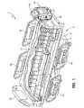
- Fig. 1shows an embodiment of a patient support or mattress 10 in accordance with the present invention.
- Patient support 10is positioned on an exemplary bed 2.
- Bed 2as illustrated, is a hospital bed including a frame 4, a headboard 36, a footboard 38, and a plurality of siderails 40.
- Frame 4 of the exemplary bed 2generally includes a deck 6 supported by a base 8.
- Deck 6includes one or more deck sections (not shown), some or all of which maybe articulating sections, i.e., pivotable with respect to base 8.
- patient support 10is configured to be supported by deck 6.
- Patient support 10has an associated control unit 42, which controls inflation and deflation of certain internal components of patient support 10, among other things.
- Control unit 42includes a user interface 44, which enables caregivers, service technicians, and/or service providers to configure patient support 10 according to the needs of a particular patient. For example, support characteristics of patient support 10 may be adjusted according to the size, weight, position, or activity of the patient.
- Patient support 10can accommodate a patient of any size, weight, height or width. It is also within the scope of the present invention to accommodate bariatric patients of up to 1000 pounds (453.6 kg) or more. To accommodate patients of varied sizes, the patient support may include a width of up to 50 inches (127 cm) or more.
- User interface 44is password-protected or otherwise designed to prevent access by unauthorized persons.
- User interface 44also enables patient support 10 to be adapted to different bed configurations.
- deck 6maybe a flat deck or a step or recessed deck.
- a caregivermay select the appropriate deck configuration via user interface 44.
- An exemplary control unit 42 and user interface 44are described in detail in U.S. Provisional Patent Application Serial No. 60/687,708 (Attorney Docket No. 8266-1407), filed July 8, 2005, and corresponding PCT application (Attorney Docket No. 8266-1555) assigned to the assignee of the present invention.
- patient support 10has a head end 32 generally configured to support a patient's head and/or upper body region, and a foot end 34 generally configured to support a patient's feet and/or lower body region.
- Patient support 10includes a cover 12 which defines an interior region 14.
- interior region 14includes a first layer 20, a second layer 50, and a third layer 52.
- other embodiments of the present inventionmay not include all three of these layers, or may include additional layers.
- first layer 20includes a support material
- second layer 50includes a plurality of vertically-oriented inflatable bladders located underneath layer 20
- third layer 52includes a plurality of pressure sensors located underneath the vertical bladders of second layer 50, as more particularly described below.
- interior region 14Also located within interior region 14 are a plurality of bolsters 54, one or more filler portions 56, and a pneumatic valve control box, valve box, control box, or pneumatic box 58.
- a fire-resistant materialmay also be included in the interior region 14.
- couplers 46are conventional woven or knit or fabric straps including a D-ring or hook and loop assembly or Velcro®-brand strip or similar fastener. It will be understood by those skilled in the art that other suitable couplers, such as buttons, snaps, or tethers may also be used equally as well.
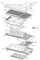
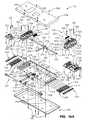
- FIG. 3Components of one embodiment of a patient support in accordance with the present invention are shown in exploded view in Fig. 3 .
- This embodiment of patient support 10includes a top cover portion 16 and a bottom cover portion 18.
- Top cover portion 16 and bottom cover portion 18couple together by conventional means (such as zipper, Velcro® strips, snaps, buttons, or other suitable fastener) to form cover 12, which defines interior region 14. While a plurality of layers and/or components are illustrated within interior region 14, it will be understood by those of skill in the art that the present invention does not necessarily require all of the illustrated components to be present.
- a first support layer 20is located below top cover portion 16 in interior region 14.
- First support layer 20includes one or more materials, structures, or fabrics suitable for supporting a patient, such as foam, inflatable bladders, or three-dimensional material. Suitable three-dimensional materials include Spacenet, Tytex, and/or similar materials. One embodiment of a suitable three dimensional material for support layer 20 is shown in Fig. 4 , described below.
- a second support layer 50 including one or more inflatable bladder assembliesis located underneath the first support layer 20.
- the illustrated embodiment of the second support layer 50includes first, second and third bladder assemblies, namely, a head section bladder assembly 60, a seat section bladder assembly 62, and a foot section bladder assembly 64.
- first, second and third bladder assembliesnamely, a head section bladder assembly 60, a seat section bladder assembly 62, and a foot section bladder assembly 64.
- other embodimentsinclude only one bladder assembly extending from head end 32 to foot end 34, or other arrangements of multiple bladder assemblies, for example, including an additional thigh section bladder assembly.
- the illustrated bladder assemblies 60, 62, 64 and their componentsare described below with reference to Figs. 5-19 .
- bladder assemblies disclosed hereinare formed from a lightweight, flexible air-impermeable material such as a polymeric material like polyurethane, urethane-coated fabric, vinyl, or rubber.
- a pressure-sensing layer 69illustratively including first and second sensor pads, namely a head sensor pad 68 and a seat sensor pad 70, is positioned underneath bladder assemblies 60, 62, 64.
- Head sensor pad 68is generally aligned underneath head section bladder assembly 60
- seat sensor pad 70is generally aligned underneath seat section bladder assembly 62, as shown.
- Head filler 66maybe positioned adjacent head sensor pad 68 near head end 32 so as to properly position head sensor pad 68 underneath the region of patient support 10 most likely to support the head or upper body section of the patient.
- a single sensor pad or additional sensor padsfor example, located underneath foot section bladder assembly 64, and/or different alignments of the sensor pads, are provided.
- Sensor pads 68, 70are described below with reference to Figs. 20-21 .
- a turn-assist cushion or turning bladder or rotational bladder 74is located below sensor pads 68, 70.
- the exemplary turn-assist cushion 74 shown in Fig. 3includes a pair of inflatable bladders 74a, 74b.
- Another suitable rotational bladder 74is a bellows-shaped bladder.
- Another suitable turn-assist cushionis disclosed in, for example, U.S. Patent No. 6,499,167 to Ellis, et al ., which patent is owned by the assignee of the present invention and incorporated herein by this reference.
- Turn-assist cushions 74are not necessarily a required element of the present invention.
- a plurality of other support components 66, 72, 76, 78, 80, 84, 86, 90are also provided in the embodiment of Fig. 3 .
- One or more of these support componentsare provided to enable patient support 10 to be used in connection with a variety of different bed frames, in particular, a variety of bed frames having different deck configurations.
- One or more of these support componentsmaybe selectively inflated or deflated or added to or removed from patient support 10 in order to conform patient support 10 to a particular deck configuration, such as a step or recessed deck or a flat deck.
- the support components illustrated in Fig. 3are made of foam, inflatable bladders, three-dimensional material, other suitable support material, or a combination of these.
- head filler 66includes a plurality of foam ribs extending transversely across patient support 10. Head filler 66 could also be an inflatable bladder.
- Filler portion 72includes a foam layer positioned substantially underneath the sensor pads 68, 70 and extending transversely across the patient support 10. In the illustrated embodiment, filler portion 72 includes a very firm foam, such as polyethylene closed-cell foam, with a 1 ⁇ 2-inch thickness.
- Head bolster assembly 76, seat bolster assembly 78, and foot section bolster assembly 86each include longitudinally-oriented inflatable bladders spaced apart by coupler plates 144.
- Bolster assemblies 76, 78, 86are described below with reference to Fig. 22 .
- first foot filler portion 80includes a plurality of inflatable bladders extending transversely across patient support 10
- second foot filler portion 84includes a foam member, illustratively with portions cut out to allow for retractability of the foot section or for other reasons.
- Deck filler portion 90includes a plurality of transversely-extending inflatable bladders. As illustrated, deck filler portion 90 includes two bladder sections located beneath the head and seat sections of the mattress, respectively, and is located outside of cover 12. Deck filler portion 90 may include one or more bladder regions, or maybe located within interior region 14, without departing from the scope of the present invention.
- a pneumatic valve box 58and an air supply tube assembly 82.
- Receptacle 88is sized to house pneumatic valve box 58.
- receptacle 88is coupled to bottom cover portion 18 by Velcro® strips.
- Pneumatic box 58is described below with reference to Figs. 14A-B .
- support layer 20includes a breathable or air permeable material which provides cushioning or support for a patient positioned thereon and allows for circulation of air underneath a patient.
- the circulated airmaybe at ambient temperature, or maybe cooled or warmed in order to achieve desired therapeutic effects.
- support layer 20includes or is enclosed in a low friction air permeable material (such as spandex, nylon, or similar material) enclosure that allows support layer 20 to move with movement of a patient on patient support 10, in order to reduce shear forces, for instance.
- a low friction air permeable materialsuch as spandex, nylon, or similar material
- the enclosureis made of a non-air permeable, moisture/vapor permeable material such as Teflon or urethane-coated fabric.
- FIG. 4an exemplary three-dimensional material suitable for use in support layer 20 is depicted.
- This illustrated embodiment of support layer 20includes a plurality of alternating first and second layers 27, 29.
- Each layer 27, 29includes first and second sublayers 28, 30.
- the sublayers 28, 30are positioned back-to-back and each sublayer 28, 30 includes a plurality of peaks or semicircular, cone, or dome-shaped projections 22 and troughs or depressions 24.
- a separator material 26is provided between the first and second sublayers 28, 30. In other embodiments, separator material 26 may instead or in addition be provided between the layers 27, 29, or not at all.
- any number of layers and sublayersmaybe provided as maybe desirable in a particular embodiment of support layer 20. Certain embodiments include 4 layers and other embodiments include 8 layers. In general, 0-20 layers of three dimensional material are included in support layer 20.
- Suitable three-dimensional materials for use in support layer 20include a polyester weave such as Spacenet, manufactured by Freudenberg & Co. of Weinheim, Germany, Tytex, available from Tytex, Inc. of Rhode Island, U.S.A., and other woven, nonwoven, orknit breathable support materials or fabrics having resilient portions, microfilaments, monofilaments, or thermoplastic fibers.
- Other embodiments of support layers and suitable three dimensional materialsare described in U.S. Patent Application Serial No. 11/119,980 , entitled PRESSURE RELIEF SUPPORT SURFACE (Attorney Docket No. 8266-1220), filed on May 2, 2005, and assigned to the assignee of the present invention.
- FIG. 5An exemplary second support layer including a base 96 and a plurality of inflatable bladders 50 is shown in the side view of Fig. 5 .
- Inflatable bladders 50extend upwardly away from base 96 along a vertical axis 101.
- Inflatable bladders 50are arranged into a plurality of bladder zones, namely head bladder zone 60, seat bladder zone 62, and foot bladder zone 64.
- First and second foot filler portions 80, 84 and tube assembly 82are located in the foot end 34 of patient support 10 below foot bladder assembly 64.
- Pneumatic valve box 58is also located in foot end 34 of patient support 40 underneath foot bladder zone 64. In other embodiments, pneumatic box 58 maybe located elsewhere in patient support 10 or outside patient support 10.
- a top view of the above-described embodiment of patient support 10is provided, with cover 12, support layer 20, and foot bladder assembly 64 removed to show the arrangement of one embodiment of a high air loss unit 91 and pneumatic box 58 in the foot section 34.
- High air loss unit 91includes a delivery tube 92 and an air distributor 94.
- Pneumatic box 58includes valves, circuitry, and other components for connecting vertical bladders 50 to an air supply 152 ( Fig. 13 ) for inflation and deflation of vertical bladders 50.
- Pneumatic box 58is described below with reference to Figs. 14A and 14B .
- High air loss devicesare similar to low air loss devices.
- a low air loss devicetypically includes openings to allow air to exit from the air bladders.
- the air from a high air loss devicedoes not exit from the air bladders.
- High air loss devicesas described herein, move air at about 2 to 10 CFM (3 ⁇ 398 to 16 ⁇ 990 m 3/9 ). Both low air loss and high air loss devices aid in controlling the moisture and the temperature from the patient.
- Delivery tube 92is connected to an air supply and provides air to air distributor 94.
- delivery tubeextends transversely and/or diagonally across the width of patient support 10 and maybe curved or angled toward seat section bladder zone 62.
- Tube 92 and distributor 94maybe made of a lightweight air impermeable material such as plastic.
- air distributor 94is coupled to an end of delivery tube 92 located near seat section bladder zone 62.
- Air distributor 94is an elongated hollow member including one or more apertures 93 which allow air to exit the tube 92 and circulate among vertical bladders 50 and three-dimensional material 20. In certain embodiments, the air is directed upwardly through support layer 20.
- a vent(not shown) is provided in cover 12 to allow the circulated air to exit interior region 14. The vent is generally located on the opposite end of patient support 10 from the supply tube 92.
- An additional ventmaybe provided in the three-dimensional material enclosure, in embodiments where three-dimensional material 20 is enclosed in an enclosure within interior region 14 as discussed above. In those embodiments, the vent is also generally located opposite the supply tube 92.
- cover 12may include a breathable or air permeable material allowing for air to flow upwardly through the cover 12 to the patient.
- a single supply tubemaybe provided in place of delivery tube 92 and air distributor 94. While shown in the illustrated embodiment, the above-described air circulating feature is not necessarily a required component of the present invention.
- high air loss device 91'includes a supply tube 600 and an enclosure 602.
- Enclosure 602includes a head end 604 and a foot end 606.
- Supply tube 600attaches to enclosure 602 at the foot end 606.
- Enclosure 602includes an oblong opening 612 near head end 604 for allowing air to exit the enclosure and the support layer 20 having a plurality of layers of three dimensional material, see above for greater description.
- the plurality of layers of three dimensional materialmay have the dimples facing upwards towards the patient or facing downward away from the patient.
- Enclosure 602maybe formed of a vapor permeable and air impermeable material, as described above.
- Opening 612may also include a series of slits.
- opening 614runs approximately the entire width of the cover 12' and includes snaps (not shown) to close portions of the opening.
- opening 614maybe be an air permeable material instead of an opening, or may include a zipper or Velcro® or hook and loop type fasteners instead of snaps.
- a fire resistant material 16is placed on the enclosure 602.
- the fire resistant material 16includes a loose weave making the fire resistant material air permeable.
- support layer 20includes first, second, third, and fourth layers of three dimensional material 618, 620, 622, 624.
- First layer 618 and second layer 620are attached at a plurality of first attachment locations 626 forming a plurality of upper channels 628.
- Third layer 622 and fourth layer 624are attached at a plurality of second attachment locations 630 forming a plurality of lower channels 632.
- an attachment pointis located at a peak of one layer adjacent a valley of an adjoining layer.
- the airflows through upper and lower channels 628, 632.
- the airalso flows through an outer region 634 located within the enclosure 602.
- Upper and lower channels 628, 632allow air to more easily flow under the patient.
- Supply tube 600includes an outer body 636 and an inner body 638.
- Outer body 636maybe formed of the same material as the enclosure.
- Inner body 638is formed from a layer of rolled three dimensional material. The three dimensional material aids in preventing supply tube 600 from kinking or collapsing which may cut off or reduce the air supply to the enclosure 602.
- supply tube 600maybe formed from PVC, plastic, or any other conventional tubing material.
- enclosure 602does not include support layer 20.
- the opening 612maybe located near foot end 606 or along at least one of the sides of the enclosure.
- supply tube 600attaches to enclosure 602 at the head end 604 or anywhere on the enclosure such as on a top surface 608, a bottom surface 610, or on a side surface (not shown) of the enclosure.
- supply tube 600is integral with enclosure 602. In other embodiments, supply tube 600 attaches to a fitting (not shown).
- supply tube 600is split by a T-fitting (not shown) and attaches to enclosure 602 in two or more locations.
- the supply tube in this embodimentis formed of PVC but may be formed from plastic or any other conventional tubing material.
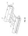
- Fig. 12depicts a bolster assembly 76, 78.
- Bolster assemblies 76, 78are generally configured to support portions of a patient along the longitudinal edges of patient support 10.
- One or more bolster assemblies 76, 78maybe provided in order to conform patient support 10 to a particular bed frame configuration, to provide additional support along the edges of patient support 10, aid in ingress or egress of a patient from patient support 10, maintain a patient in the center region of patient support 10, or for other reasons.
- internal air pressure of the bolster bladdersmaybe higher than the internal bladder pressure of assembles 60, 62, 64, or maybe increased or decreased in real time, to accomplish one of these or other objectives.
- Each bolster assembly 76,78includes a plurality of bolsters, namely, an upper bolster 140 and a lower bolster 142, with the upper bolster 140 being positioned above the lower bolster 142.
- Each upper and lower bolster combination 140, 142is configured to be positioned along a longitudinal edge of patient support 10.
- Each upper and lower bolster combination 140, 142is enclosed in a cover 138.
- the bolsters 140, 142are inflatable bladders.
- either or both bolsters 140, 142maybe constructed of foam, or filled with three-dimensional material, fluid, or other suitable support material.
- upper bolster 140includes two layers of foam: a viscoelastic top layer and a non visco elastic bottom layer, while lower bolster 142 is an inflatable bladder.
- the bolsters 140, 142maybe inflated together, or separately, as shown in Fig. 13 , described below.
- Each bolster combination 140, 142is coupled to one end of one or more support plates 144 which provide support for other components of patient support 10 including vertical bladders 50.
- Support plates 144maybe made of a substantially rigid or stiff yet lightweight material such as molded plastic. In other embodiments, plates 144 maybe constructed of stainless steel or steel, if additional weight is desired, i.e. for addition, collapsibility for ease of storage of patient support 10, for instance. Support plates 144 maybe provided in order to give support to patient support 10 particularly during transport, for ease of assembly, or for other reasons.
- each support plate 144is a rectangular member extending transversely across the width of the mattress 10. As shown in the drawings, there are five such rib-like members 144 spaced apart underneath the head and seat sections of the mattress. In other embodiments, each support plate 144 has its middle section (i.e., the section extending transversely) cut out so that only the two plate ends remain at each spaced-apart end (underneath the bolsters); thereby providing five pairs of support plates 144 spaced apart along the longitudinal length of the mattress 10.
- Bolster assembly 86is similar to bolster assemblies 76, 78 except that its upper layer includes the vertical bladders 50 of longitudinal sections 214, 216.
- Bolster assembly 86has a longitudinally-oriented bladder as its lower bolster portion.
- FIG. 13A schematic diagram of the pneumatic control system of patient support 10 is shown in Fig. 13 . Reading Fig. 13 from second to first, there is shown a simplified top view of patient support 10 with portions removed to better illustrate the various air zones 160, a simplified side view of patient support 10, a schematic representation of pneumatic valve box 58, a schematic representation of control unit 42, and air lines 146, 148, 150 linking control unit 42, valve box 58, and air zones 160.
- air zones 160 of patient support 10are assigned as follows: zone 1 corresponds to head section bladder assembly 60, zone 2 corresponds to seat section bladder assembly 62, zone 3 corresponds to foot section bladder assembly 64, zone 4 corresponds to upper side bolsters 140, zone 5 corresponds to lower side bolsters 142, zone 6 corresponds to upper foot bolsters 140, zone 7 corresponds to lower foot bolsters 142, zone 8 corresponds to first turn-assist bladder 74, zone 9 corresponds to second turn-assist bladder 74, zone 10 corresponds to deck filler 90, and zone 11 corresponds to foot filler 80.
- Valve box 58is located in the foot section 34 of patient support 10.
- valve box 58is releasably coupled to bottom portion 18 of cover 12 in interior region 14, i.e., by one or more Vecro®-brand fasteners or other suitable coupler.
- Each air line 150is coupled at one end to an inlet port 135 on the corresponding bladder or bladder assembly. Each air line 150 is coupled at its other end to a valve assembly 162.
- Each valve assembly 162includes first or fill valve 163 and a second or vent valve 165.
- First valves 163are coupled to air supply 152 of control unit 42 by air lines 148. First valves 163 thereby operate to control inflation of the corresponding zone 160 i.e. to fill the zone with air.
- Second valves 165operate to at least partially deflate or vent the corresponding zone 160, for example, if the internal air pressure of the zone 160 exceeds a predetermined maximum, or if deflation is necessary or desirable in other circumstances (such as a medical emergency, or for transport of patient support 10).
- Each valve 163, 165has an open mode 224 and a closed mode 226, and a switching mechanism 228 (such as a spring) that switches the value from one mode to another based on control signals from control unit 42.
- a switching mechanism 228such as a spring
- closed mode 226air flows from air supply 152 through the value 163 to the respective zone 160 to inflate the corresponding bladders, or in the case of vent valves 165, from the zone 160 to atmosphere.
- open mode 228no inflation or deflation occurs.
- an emergency vent valve 230is provided to enable quick deflation of turning bladders 74 which draws air from atmosphere through a filter 164 and also vents air to atmosphere through filter 164.
- Air supply 152is an air pump, compressor, blower, or other suitable air source.
- Air supply 152is coupled to a switch valve 155 by air line 146.
- Switch valve 166operates to control whether inflation or deflation of a zone occurs.
- An optional proportional valve 171maybe coupled to air line 148 to facilitate smooth inflation or deflation of turn-assist bladders 74, or for other reasons.
- valve box 58includes a first valve module 156 and a second valve module 158.
- First valve module 156includes valves generally associated with a patient's first side (i.e., first side, from the perspective of a patient positioned on patient support 10) and second valve module 158 includes valves generally associated with a patient's second side (i.e., second side).
- the various zones 160are separately inflatable. Certain of the zones 160 are inflated or deflated to allow patient support 10 to conform to different bed frame configurations.
- the deck filler 90(zone 10 in Fig. 23) is inflated to conform patient support 10 to certain bed frame configurations, such as step deck configurations including the TotalCare® and CareAssist® bed frames, made by Hill-Rom, Inc., the assignee of the present invention, but is deflated when patient support 10 is used with a flat deck bed frame, such as the Advanta® bed made by Hill-Rom, Inc.
- the foot filler 80zone 11 in Fig.
- the lower side bolsters 142(zone 5 in Fig. 23) are not inflated when patient support 10 is used with a VersaCare® bed.
- the lower foot bolsters 142(zone 7 in Fig. 23) are inflated when patient support 10 is used on flat decks or other bed frames, including the Advanta® and VersaCare® bed frames made by Hill-Rom, Inc.
- Figs. 11A and 11Bare a simplified schematic diagram of a control system and the patient support or mattress 10 of the present invention.
- Fig. 24Aillustrates the patient support 10 including the various components of patient support 10 whereas Fig. 24B illustrates the control unit 42 and various components therein.
- the patient support 10includes the sensor pad 52 which is coupled to the pneumatic valve control box 58 as previously described.
- the sensor pad 52includes a head sensor pad 68 and a seat sensor pad 70.
- the head sensor pad 68is located at the head end 32 of the mattress 10.
- the seat sensor pad 70is located at a middle portion of the mattress 10 which is located between the head end 32 and a location of the pneumatic valve control box 58.
- the seat sensor pad 70is located such that a patient laying upon the mattress 10 may have its middle portion or seat portion located thereon when in a reclined state. In addition, when the head end 32 of the mattress 10 is elevated, the seat portion of the patient is located upon the seat sensor pad 70. As previously described with respect to Fig. 3 , the head sensor pad 68 is located beneath the head section bladder assembly 60 and the seat sensor pad 70 is located beneath the seat section bladder assembly 62. Each one of the sensors of the head sensor pad 68 or the seat sensor pad 70 is located beneath on at least adjacent to one of the upstanding cylindrical bladders or cushions 50.
- a head angle sensor 502is coupled to the control box 58 where signals received from the sensor 52 may provide head angle information and pressure adjustment information for adjusting pressure in the seat bladders 62.
- the sensor pad 52is coupled through the associated cabling to the pneumatic control box 58.
- the pneumatic control box 58includes a multiplexer 508 coupled to the head sensor pad 68 and the seat sensor pad 70 through a signal and control line 510.
- the multiplexer board 508is also coupled to an air control board 512 which is in turn coupled to a first valve block 514 and a second valve block 516.
- a communication/power line 518is coupled to the control unit 42 of Fig. 11B .
- a ventilation supply line 520which provides for air flow through the patient support 10 for cooling as well as removing moisture from the patient is also coupled to the control unit 42 of Fig. 11B .
- An air pressure/vacuum supply line 522is coupled to the control unit 42 as well.
- the control unit 42 of Fig. 11 Balso illustrated in Fig. 1 , includes the display 44, which displays user interface screens, and a user interface input device 524 for inputting to the control unit 42 user selectable information, such as the selection of various functions or features of the present device.
- the selections made on the user interface input device 524control the operation of the patient support 10, which can include selectable pressure control of various bladders within the mattress 10, control of the deck 6, for instance to put the bed 2 in a head elevated position, as well as displaying the current state of the mattress or deck position, and other features.
- An algorithm control board 526is coupled to the user interface input device 524.
- the algorithm control board 526receives user generated input signals received through the input device 524 upon the selection of such functions by the user.
- the input device 524can include a variety of input devices, such as pressure activated push buttons, a touch screen, as well as voice activated or other device selectable inputs.
- the algorithm control board 526upon receipt of the various control signals through the user input device 524 controls not only the operation of the mattress 10 but also a variety of other devices which are incorporated into the control unit 42.
- the algorithm control board 526is coupled to a display board 528 which sends signals to the display 44 to which it is coupled.
- the display board 528is also connected to a speaker 530 which generates audible signals which might indicate the selection of various features at the input device 24 or indicate a status of a patient positioned on patient support (e.g. exiting) or indicate a status of therapy being provided to the patient (e.g., rotational therapy complete).
- the algorithm control board 526receives the required power from power supply 532 which includes an AC input module 534, typically coupled to a wall outlet within a hospital room.
- the algorithm control board 526is coupled to an air supply, which, in the illustrated embodiment includes a compressor 536 and a blower 538. Both the compressor 536 and the blower 538 receive control signals generated by the algorithm control board 526.
- the compressor 536is used to inflate the air bladders.
- the blower 538is used for air circulation which is provided through the ventilation supply line 520 to the mattress 10. It is, however, possible that the compressor 536 maybe used to both inflate the bladders and to circulate the air within the mattress 10.
- a pressure/vacuum switch valve 540is coupled to the compressor 536 which is switched to provide for the application of air pressure or a vacuum to the mattress 10.
- a muffler 541is coupled to the valve 540.
- the valve 540In the pressure position, air pressure is applied to the mattress 10 to inflate the mattress for support of the patient.
- the valve 540is used to apply a vacuum to the bladders therein such that the mattress maybe placed in a collapsed state for moving to another location or for providing a CPR function, for example.
- a CPR button 542is coupled to the algorithm control board 526.
- the algorithm control board 526, the compressor 536, the blower 538, and the user input device or user control module 524are located externally to the mattress and are a part of the control unit 42, which maybe located on the footboard 38 as shown in Fig. 1 .
- the sensors and sensor pad 52, the pneumatic valve control box 58, and the air control board or microprocessor 512 for controlling the valves and the sensor pad system 52are located within the mattress 10. It is within the present scope of the invention to locate some of these devices within different sections of the overall system, for instance, such that the algorithm control board 526 could be located within the mattress 10 or the air control board 512 could be located within the control unit 42.
- control box 58includes a multiplexer 252 and an air control board 250.
- Control board 250is coupled to multiplexer 252 by a jumper 254.
- Multiplexer 252is further coupled to head sensor pad 68 and seat sensor pad 70 through a signal and control line (not shown).
- Control board 250is also coupled to first valve module 156 and second valve module 158 by wire leads 251.
- a communication/power line 258couples control board 250 to the control unit 42.
- Communication line 258couples to a communication plug 259 of control board 250.
- Jumper 254couples multiplexer 252 to control board 250 for power and access to communication line 258.
- Wire leads 251provide actuation power to first and second valve modules 156, 158.
- first and second valve modules 156, 158include fill valves 163 and vent valves 165.
- First valve module 156includes fill valves 163a-f and vent valves 165a-f.
- Second valve module 156includes fill valves 163g-l and vent valves 165g-l.
- Fill valves 163a-l and vent valves 165a-lare 12 Volt 7 Watt solenoid direct active poppet style valves in the illustrated embodiment.
- Control board 252is able to actuate each fill valve 163a-l and vent valve 165a-1 independently or simultaneously.
- Fill valves 163a-l and vent valves 165a-lare all able to be operated at the same time.
- control board 250sends a signal to the valve to be operated.
- the signalcauses a coil (not shown) within each valve to energize for 1 ⁇ 2 second and then switches to pulsate power (i.e., turn on and off at a high rate) to save power during activation.
- the activationin turn cause the valve to either open or close depending on which valve is initiated.
- Air line 148includes an outer box line assembly 260 and an inner box line assembly 262.
- Outer box line assembly 260includes an exterior inlet hose 264 and an elbow 266 coupled to exterior inlet hose 264.
- Inner box line assembly 262includes an interior inlet hose 268 coupled to elbow 266, a union tee connector 270, a first module hose 272, and a second module hose 274.
- Connector 270includes a first opening 276 to receive interior inlet hose 268, a second opening 278 to receive first module hose 272, and a third opening 280 to receive second module hose 274.
- First and second module hoses 272, 274each couple through a male coupler 282 to first and second valve modules 156, 158 respectively.
- air from air supply 152travels through supply line 148, enters outer box line assembly 260 through exterior inlet hose 264 and passes through elbow 266 to interior inlet hose 268.
- the airthen travels from inlet hose 268 to union tee connector 270 where the air is divided into first module hose 272 and second module hose 274.
- the airpasses through first and second module hoses 272, 274 into first and second valve modules 156, 158 respectively.
- the operation of first and second valve modules 156, 158is described below.
- Control box 58includes a base 284, a cover 286, and a tray 288.
- Cover 286includes a plurality of fasteners (i.e., screws) 290.
- Base 284includes a plurality of threaded cover posts 292.
- Cover posts 292are configured to receive screws 290 to couple cover 286 to base 284.
- Cover 286 and base 284define an inner region 298.
- Tray 288couples to base 284 with a plurality of rivets 291 riveted through a plurality of rivet holes 293 located on tray 288 and base 284.
- Inner box line assembly 262, first valve module 156, second valve module 158, control board 250, and multiplexer 252are contained within inner region 298.
- Base 284further includes a plurality of control board posts 294, a plurality of multiplexer posts 296, and a plurality of module posts 300.
- First and second valve modules 156, 158are coupled to module posts 300 by shoulder screws 302 and washers 304.
- Control board 250 and multiplexer 252are respectively coupled to control board posts 294 and multiplexer posts 296 by a plurality of snap mounts 306.
- First and second valve modules 156, 158attach to third air lines 150 a, b, d-f, and g-l through a plurality of couplers 308.
- Couplers 308include a first end 310 and a second end 312.
- Third air lines 150 a, b, d-f, and g-leach include a fitting (not shown) receivable by second end 312.
- Each first end 310mounts to a port 314 in first and second valve modules 156, 158.
- First end 310mounts through a plurality of openings 316 in base 284.
- a plurality of feedback couplers 318mount through a plurality of feedback openings 320 in base 284.
- Feedback couplers 318include a first feedback end 322 and a second feedback end 324.
- First feedback end 322couples to a feedback line (not shown) that in turn couples to a feedback port 135 located on each air zone 160.
- Second feedback end 324receives a feedback transfer line 326.
- Each transfer line 326couples to a pressure transducer 328 located on the control board 250.
- Pressure transducer 328receives the pressure from each air zone 160 and transmits to control unit 42 a pressure data signal representing the internal air pressure of the zone 160.
- Control unit 42uses these pressure signals to determine the appropriate pressures for certain mattress functions such as CPR, patient transfer, and max-inflate.
- Pressure signals from the transducer 328 coupled to the foot zone 160kare also used to maintain optimal pressure in foot zone 160k.
- pressure in foot zone 160k(zone 3) is computed as a percentage of the pressure in seat zone 160e (zone 2).
- the pressures in seat zone 160e and head zone 160fare determined using both the tranducers 328 and the pressure sensors 136.
- the pressures in one or more of the zones 160maybe adjusted in real time.
- fill valves 163a-l and vent valves 165a-lare coupled to various portions of patient support 10 through third air lines 150 a, b, d-f, and g-l.
- Fill valve 163a and vent valve 165aare coupled to upper foot bolsters 140c
- fill valve 163b and vent valve 165bare coupled to lower side bolsters 142 a, b
- fill valve 163cis coupled to atmosphere and vent valve 165c is reserved for future therapies.
- fill valve 163d and vent valve 165dare coupled to first turn assist 74a
- fill valve 163e and vent valve 165eare coupled to seat bladders 62
- fill valve 163f and vent valve 165fare coupled to head bladder assembly 60
- fill valve 163g and vent valve 165gare coupled to foot filler 80
- fill valve 163h and vent valve 165hare coupled to upper side bolsters 140 a, b
- fill valve 163i and vent valve 165iare coupled to deck filler 90
- fill valve 163j and vent valve 165jare coupled to first turn assist 74b
- fill valve 163k and vent valve 165kare coupled to foot bladders 164
- fill valve 1631 and vent valve 1651are coupled to lower foot bolsters 142c.
- Vent valves 165d, jare biased in the open position to vent air from first and second turn assist 74a, 74b when first and second turn assist 74a, 74b are not in use. Vent valves 165d, j return to their open position if the mattress loses power or pressure venting air from the first and second turn assist 74a, 74b. When air is vented from a zone 160, the pressure in the zone 160 after deflation is determined by the control system 42, 58 in real time rather than being predetermined.
- a userenters an input command to control unit 42.
- Control unit 42processes the input command and transmits a control signal based on the input command through communication line 258 to control board 250.
- control signalscould be based on operational information from control unit 42 to increase or decrease pressure within one or more of the zones 160 based on information obtained from transducers 328 and/or sensors 136.
- the mattress controls 42, 58are independent from operation of the bed frame 4.
- bed frame 4 and mattress 10maybe configured to exchange or share data through communication lines.
- datais communicated from bed frame 4 to mattress system 42, 58 and used to adjust support parameters of mattress 10.
- a signalis transmitted from frame 4 when foot section 34 is retracting, so that mattress systems 42, 58 responds by decreasing internal pressure of vertical bladders 50 in foot assembly 64.
- air supply 152is capable of supplying air or acting as a vacuum to remove air from zones 160.
- a microprocessor on control board 250actuates corresponding fill valve 163a-l or vent valve 165a-l based on the control signal from control unit 42. For example, if the control signal indicates the pressure in head bladder assembly 160 is to be increased fill valve 163f is actuated. However, if the control signal indicates the pressure in head bladder assembly 160 is to be decreased vent valve 165f is actuated. While in vacuum mode one or more fill valves 163a-l maybe actuated to allow for rapid removal of air within the corresponding zones.
- An angle sensor cable 256is provided to send a signal from a head angle sensor 502 to the control board 250.
- Angle sensor cable 256couples to an angle plug 257 of control board 250.
- head angle sensor 502is located within head bolster assembly 76 as indicated by Figs. 11A and 15 .
- Head angle sensor 502indicates the angle of elevation of the head end 32 of bed 2 as the head section of the frame 4 articulates upwardly raising the patient's head or downwardly lowering the patient's head.
- angle sensor 502transmits the angle of head end 32 to all nodes or circuit boards within the mattress control system 42, 58.
- Angle sensor 502generates an indication or indicator signal when head end 32 is at an angle of at least 5°, at least 30°, and at least 45°.
- the head angle indicationis transmitted to the control unit 42 which evaluates and processes the signal.
- head end 32When head end 32 is at an angle above 30° turn assist 74 becomes inoperative primarily for patient safety reasons.
- head end 32 is at an angle above 45° informationis transmitted to control unit 42 for use in the algorithms.
- the 5° angle indicationis primarily to ensure relative flatness of patient support 10.
- angle sensor 502is a ball switch. In an alternative embodiment, angle sensor 502 maybe a string potentiometer.
- First ball 702actuates when the head end 32 is at an angle of at least 5° moving first ball 702 from a first position 708 to a second position 710.
- Second ball 704indicates when the head end 32 is at an angle of at least 30° moving second ball 704 from a first position 712 to a second position 714.
- Third ball 706indicates when the head end 32 is at an angle of at least 45° moving third ball 706 from a first position 716 to a second position 718.
- Fig. 17shows patient support 10 in a transportation position on a pallet 750.
- air supply 42is capable of providing a vacuum to evacuate the air from within patient support 10. This allows patient support 10 to be folded.
- couplers 46hold patient support 10 in the transportation position.
- Support plates 144are provided as separate plates to aid in the folding process. As patient support 10 is folded, any remaining air not evacuated by the air supply 42 is forced from the patient support 10.
- a side view of another embodiment of a patient support 10(not in accord with the invention) is shown with an enclosure 602.
- Enclosure 602includes a top surface 608, a fire-resistant material 16 beneath the top surface 608, and a three-dimensional layer 20 beneath the fire-resistant material 16.
- the three-dimensional layer 20includes a top membrane layer 220 and a bottom membrane layer 222.
- the top membrane layer 220 and bottom membrane layer 222can be impermeable to air and the three-dimensional material 20 can include Spacenet, Tytex, and/or similar material, as disclosed in Figs. 4 and 9 and corresponding descriptions, for example.
- One or more inflatable bladders 50are provided as an additional support layer beneath the bottom membrane layer 222.
- a pneumatic box 58 and an additional layer 84are provided at the foot end 34 of the patient support 10.
- Layer 84includes a retractable foam material in the illustrated embodiment.
- airis supplied by an air supply (not shown) through a supply tube 600 located near one end 34 of the patient support 10.
- the supply tube 600is coupled to a fitting 700 which also attaches to distributing tubes 800.
- This arrangementis further shown in Fig. 20 and described below.
- Airflows through the distributing tubes 800 and into the enclosure 602 in a direction 660 from the one end 34 to the other end 32 of the patient support 10.
- the aircan be released from the enclosure 602 by a vent assembly 662 near the end 32 of the patient support 10.
- airflows from the foot end of the head end of the patient support.
- airmay flow in the reverse direction or laterally across the patient support.
- FIG. 20another embodiment for supplying air to the enclosure 602 is shown including a supply tube 600, fitting 700, and distributing tubes 800.
- Airis received by a supply tube 600 and is transported into distributing tubes 800.
- the supply tube 600 and distributing tubes 800are attached by a fitting 700.
- the fitting 700can be a T-fitting, as shown in Fig. 20 , or any other type of suitable fitting known in the art. Air flows through the distributing tubes 800 and into the enclosure 602.
- the cloth manifold arrangement 810includes a cloth manifold 820 made of an outer layer material 822 that can be impermeable to air.
- the cloth manifold 820is a soft material that provides additional comfort to the patient and includes a receiving portion 824 and a plurality of distributing portions 826.
- the receiving portion 824can attach to a flow tube (not shown) or directly to an air supply (not shown).
- the distributing portions 826are coupled to the enclosure 602 by one or more Velcro®-brand strips or similar fasteners 828.
- the distributing portions 826may also include hollow receiving apertures 832 used for additional fastening the distributing portions 826 to the enclosure 602.
- the cloth manifold 820may include an inner layer 830, as shown in Fig. 22 , made from three-dimensional material 20 such as Spacenet, Tytex, and/or similar material as described above.
- the inner layer 830may be configured to help prevent the cloth manifold 820 from kinking or collapsing which may cut off or reduce the air supply to the enclosure 602.
Landscapes
- Health & Medical Sciences (AREA)
- Nursing (AREA)
- Life Sciences & Earth Sciences (AREA)
- Animal Behavior & Ethology (AREA)
- General Health & Medical Sciences (AREA)
- Public Health (AREA)
- Veterinary Medicine (AREA)
- Invalid Beds And Related Equipment (AREA)
- Mattresses And Other Support Structures For Chairs And Beds (AREA)
Description
- The present invention relates to a device for supporting a patient, such as a mattress. In particular, the present invention relates to patient supports appropriate for use in hospitals, acute care facilities, and other patient care environments. Further, the present invention relates to pressure relief support surfaces and support surfaces that are configured to accommodate and operate with a variety of sizes and styles of beds, bed frames, and patient types.
- Known patient supports are disclosed in, for example,
U.S. Patent No. 5,630,238 to Weismiller et al .,U.S. Patent No. 5,715,548 to Weismiller et al .,U.S. Patent No. 6,076,208 to Heimbrock et al .,U.S. Patent No. 6,240,584 to Perez et al .,U.S. Patent No. 6,320,510 to Menkedick et al .,U.S Patent No. 6,378,152 to Washburn et al ., andU.S. Patent No. 6,499,167 to Ellis et al ., all of which are owned by the assignee of the present invention. GB 2212058 - The present invention provides a patient support comprising a body including a bladder, and an air loss device including a tube, wherein the tube receives a volume of air from an air supply, the tube including a plurality of apertures configured to deliver the air received, characterized in that the support further comprises a cover, the body located within the cover and the air being delivered across the bladder within the cover.
- Additional features and advantages of the invention will become apparent to those skilled in the art upon consideration of the following detailed description of illustrated embodiments exemplifying the best mode of carrying out the invention as presently perceived.
- Aspects of the present invention are more particularly described below with reference to the following figures, which illustrate exemplary embodiments of the present invention:
Fig. 1 is a perspective view of a patient support positioned on an exemplary hospital bed, with a portion of the patient support being cut away to show interior components of the patient support;Fig. 2 is a perspective view of a patient support, with a portion being cut away to show interior components of the patient support;Fig. 3 is an exploded view of components of the illustrated embodiment of a patient support;Fig. 4 is a schematic view of an exemplary three-dimensional support material;Fig. 5 is a side view of selected components of the illustrated embodiment of a patient support;Fig. 6 is a top view of components of a patient support also shown inFig. 5 ;Fig. 7 is a side view of selected components of an alternative embodiment of a patient support not in accord with the invention;Fig. 8 is a top view showing air flow through the alternative embodiment of the patient support shown inFig. 7 ;Fig. 9 is an exploded end view of the alternative embodiment of the patient support shown inFig. 7 ;Fig. 10 is a perspective view of an air supply tube for a high air loss device;Figs. 11 A and 11B are schematic diagrams of portions of a control system for the illustrated patient support;Fig. 12 is a perspective view of an exemplary bolster assembly;Fig. 13 is a schematic view of air zones of the illustrated patient support and associated air supply system;Fig. 14A is an exploded view of an exemplary pneumatic assembly;Fig. 14B is a perspective view of the pneumatic assembly ofFig. 14A Fig. 15 !is a perspective view of a patient support, with a portion being cut away to show interior components, including an angle sensor, of the patient support;Figs. 16A-C are diagrammatic views showing ball switches located within the angle sensor;Fig. 17 is a perspective view of the patient support in a transportation position;Fig. 18 is a side view of selected components of an alternative embodiment of a patient support not accord with the invention;Fig. 19 is a top view showing air flow through the alternative embodiment of the patient support shown inFig. 18 ;Fig. 20 is a schematic view of a supply tube attaching to an enclosure through a T-fitting;Fig. 21 is a schematic view of a cloth manifold attaching to an enclosure; andFig. 22 is a schematic view of various layers of a cloth manifold.Fig. 1 shows an embodiment of a patient support ormattress 10 in accordance with the present invention.Patient support 10 is positioned on anexemplary bed 2.Bed 2, as illustrated, is a hospital bed including aframe 4, aheadboard 36, afootboard 38, and a plurality ofsiderails 40.Frame 4 of theexemplary bed 2 generally includes adeck 6 supported by abase 8.Deck 6 includes one or more deck sections (not shown), some or all of which maybe articulating sections, i.e., pivotable with respect tobase 8. In general,patient support 10 is configured to be supported bydeck 6.Patient support 10 has an associatedcontrol unit 42, which controls inflation and deflation of certain internal components ofpatient support 10, among other things.Control unit 42 includes auser interface 44, which enables caregivers, service technicians, and/or service providers to configurepatient support 10 according to the needs of a particular patient. For example, support characteristics ofpatient support 10 may be adjusted according to the size, weight, position, or activity of the patient.Patient support 10 can accommodate a patient of any size, weight, height or width. It is also within the scope of the present invention to accommodate bariatric patients of up to 1000 pounds (453.6 kg) or more. To accommodate patients of varied sizes, the patient support may include a width of up to 50 inches (127 cm) or more.User interface 44 is password-protected or otherwise designed to prevent access by unauthorized persons.User interface 44 also enablespatient support 10 to be adapted to different bed configurations. For example,deck 6 maybe a flat deck or a step or recessed deck. A caregiver may select the appropriate deck configuration viauser interface 44. Anexemplary control unit 42 anduser interface 44 are described in detail inU.S. Provisional Patent Application Serial No. 60/687,708 - Referring now to
Fig. 2 ,patient support 10 has ahead end 32 generally configured to support a patient's head and/or upper body region, and afoot end 34 generally configured to support a patient's feet and/or lower body region.Patient support 10 includes acover 12 which defines aninterior region 14. In the illustrated embodiment,interior region 14 includes afirst layer 20, asecond layer 50, and athird layer 52. However, it will be understood by those skilled in the art that other embodiments of the present invention may not include all three of these layers, or may include additional layers. - In the illustrated embodiment,
first layer 20 includes a support material,second layer 50 includes a plurality of vertically-oriented inflatable bladders located underneathlayer 20, andthird layer 52 includes a plurality of pressure sensors located underneath the vertical bladders ofsecond layer 50, as more particularly described below. - Also located within
interior region 14 are a plurality ofbolsters 54, one ormore filler portions 56, and a pneumatic valve control box, valve box, control box, orpneumatic box 58. A fire-resistant material (not shown) may also be included in theinterior region 14. Patient support 10 maybe coupled todeck 6 by one ormore couplers 46. Illustratively,couplers 46 are conventional woven or knit or fabric straps including a D-ring or hook and loop assembly or Velcro®-brand strip or similar fastener. It will be understood by those skilled in the art that other suitable couplers, such as buttons, snaps, or tethers may also be used equally as well.- Components of one embodiment of a patient support in accordance with the present invention are shown in exploded view in
Fig. 3 . This embodiment ofpatient support 10 includes atop cover portion 16 and abottom cover portion 18.Top cover portion 16 andbottom cover portion 18 couple together by conventional means (such as zipper, Velcro® strips, snaps, buttons, or other suitable fastener) to formcover 12, which definesinterior region 14. While a plurality of layers and/or components are illustrated withininterior region 14, it will be understood by those of skill in the art that the present invention does not necessarily require all of the illustrated components to be present. - A
first support layer 20 is located belowtop cover portion 16 ininterior region 14.First support layer 20 includes one or more materials, structures, or fabrics suitable for supporting a patient, such as foam, inflatable bladders, or three-dimensional material. Suitable three-dimensional materials include Spacenet, Tytex, and/or similar materials. One embodiment of a suitable three dimensional material forsupport layer 20 is shown inFig. 4 , described below. - Returning to
Fig. 3 , asecond support layer 50 including one or more inflatable bladder assemblies, is located underneath thefirst support layer 20. The illustrated embodiment of thesecond support layer 50 includes first, second and third bladder assemblies, namely, a headsection bladder assembly 60, a seatsection bladder assembly 62, and a footsection bladder assembly 64. However, it will be understood by those skilled in the art that other embodiments include only one bladder assembly extending fromhead end 32 to footend 34, or other arrangements of multiple bladder assemblies, for example, including an additional thigh section bladder assembly. The illustratedbladder assemblies Figs. 5-19 . In general, bladder assemblies disclosed herein are formed from a lightweight, flexible air-impermeable material such as a polymeric material like polyurethane, urethane-coated fabric, vinyl, or rubber. - A pressure-sensing layer 69 illustratively including first and second sensor pads, namely a
head sensor pad 68 and aseat sensor pad 70, is positioned underneathbladder assemblies Head sensor pad 68 is generally aligned underneath headsection bladder assembly 60, andseat sensor pad 70 is generally aligned underneath seatsection bladder assembly 62, as shown.Head filler 66 maybe positioned adjacenthead sensor pad 68 near head end 32 so as to properly positionhead sensor pad 68 underneath the region ofpatient support 10 most likely to support the head or upper body section of the patient. In other embodiments, a single sensor pad or additional sensor pads, for example, located underneath footsection bladder assembly 64, and/or different alignments of the sensor pads, are provided.Sensor pads Figs. 20-21 . - In the illustrated embodiment, a turn-assist cushion or turning bladder or
rotational bladder 74 is located belowsensor pads assist cushion 74 shown inFig. 3 includes a pair ofinflatable bladders rotational bladder 74 is a bellows-shaped bladder. Another suitable turn-assist cushion is disclosed in, for example,U.S. Patent No. 6,499,167 to Ellis, et al ., which patent is owned by the assignee of the present invention and incorporated herein by this reference. Turn-assistcushions 74 are not necessarily a required element of the present invention. - A plurality of
other support components Fig. 3 . One or more of these support components are provided to enablepatient support 10 to be used in connection with a variety of different bed frames, in particular, a variety of bed frames having different deck configurations. One or more of these support components maybe selectively inflated or deflated or added to or removed frompatient support 10 in order to conformpatient support 10 to a particular deck configuration, such as a step or recessed deck or a flat deck. - The support components illustrated in
Fig. 3 are made of foam, inflatable bladders, three-dimensional material, other suitable support material, or a combination of these. For example, as illustrated,head filler 66 includes a plurality of foam ribs extending transversely acrosspatient support 10.Head filler 66 could also be an inflatable bladder.Filler portion 72 includes a foam layer positioned substantially underneath thesensor pads patient support 10. In the illustrated embodiment,filler portion 72 includes a very firm foam, such as polyethylene closed-cell foam, with a ½-inch thickness. - Head bolster
assembly 76, seat bolsterassembly 78, and foot section bolsterassembly 86 each include longitudinally-oriented inflatable bladders spaced apart bycoupler plates 144. Bolsterassemblies Fig. 22 . - As illustrated, first
foot filler portion 80 includes a plurality of inflatable bladders extending transversely acrosspatient support 10, and secondfoot filler portion 84 includes a foam member, illustratively with portions cut out to allow for retractability of the foot section or for other reasons.Deck filler portion 90 includes a plurality of transversely-extending inflatable bladders. As illustrated,deck filler portion 90 includes two bladder sections located beneath the head and seat sections of the mattress, respectively, and is located outside ofcover 12.Deck filler portion 90 may include one or more bladder regions, or maybe located withininterior region 14, without departing from the scope of the present invention. - Also provided in the illustrated embodiment are a
pneumatic valve box 58 and an airsupply tube assembly 82.Receptacle 88 is sized to housepneumatic valve box 58. In the illustrated embodiment,receptacle 88 is coupled tobottom cover portion 18 by Velcro® strips.Pneumatic box 58 is described below with reference toFigs. 14A-B . - In the illustrated embodiment,
support layer 20 includes a breathable or air permeable material which provides cushioning or support for a patient positioned thereon and allows for circulation of air underneath a patient. The circulated air maybe at ambient temperature, or maybe cooled or warmed in order to achieve desired therapeutic effects. - Also in the illustrated embodiment,
support layer 20 includes or is enclosed in a low friction air permeable material (such as spandex, nylon, or similar material) enclosure that allowssupport layer 20 to move with movement of a patient onpatient support 10, in order to reduce shear forces, for instance. In other embodiments, the enclosure is made of a non-air permeable, moisture/vapor permeable material such as Teflon or urethane-coated fabric. - In
Fig. 4 , an exemplary three-dimensional material suitable for use insupport layer 20 is depicted. This illustrated embodiment ofsupport layer 20 includes a plurality of alternating first andsecond layers layer second sublayers sublayers sublayer projections 22 and troughs ordepressions 24. Aseparator material 26 is provided between the first andsecond sublayers separator material 26 may instead or in addition be provided between thelayers - Any number of layers and sublayers maybe provided as maybe desirable in a particular embodiment of
support layer 20. Certain embodiments include 4 layers and other embodiments include 8 layers. In general, 0-20 layers of three dimensional material are included insupport layer 20. - Suitable three-dimensional materials for use in
support layer 20 include a polyester weave such as Spacenet, manufactured by Freudenberg & Co. of Weinheim, Germany, Tytex, available from Tytex, Inc. of Rhode Island, U.S.A., and other woven, nonwoven, orknit breathable support materials or fabrics having resilient portions, microfilaments, monofilaments, or thermoplastic fibers. Other embodiments of support layers and suitable three dimensional materials are described inU.S. Patent Application Serial No. 11/119,980 - An exemplary second support layer including a
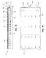
base 96 and a plurality ofinflatable bladders 50 is shown in the side view ofFig. 5 .Inflatable bladders 50 extend upwardly away frombase 96 along avertical axis 101.Inflatable bladders 50 are arranged into a plurality of bladder zones, namelyhead bladder zone 60,seat bladder zone 62, andfoot bladder zone 64. First and secondfoot filler portions tube assembly 82 are located in thefoot end 34 ofpatient support 10 belowfoot bladder assembly 64.Pneumatic valve box 58 is also located infoot end 34 ofpatient support 40 underneathfoot bladder zone 64. In other embodiments,pneumatic box 58 maybe located elsewhere inpatient support 10 or outsidepatient support 10. - In
Fig. 6 , a top view of the above-described embodiment ofpatient support 10 is provided, withcover 12,support layer 20, andfoot bladder assembly 64 removed to show the arrangement of one embodiment of a highair loss unit 91 andpneumatic box 58 in thefoot section 34. Highair loss unit 91 includes adelivery tube 92 and anair distributor 94.Pneumatic box 58 includes valves, circuitry, and other components for connectingvertical bladders 50 to an air supply 152 (Fig. 13 ) for inflation and deflation ofvertical bladders 50.Pneumatic box 58 is described below with reference toFigs. 14A and14B . High air loss devices are similar to low air loss devices. A low air loss device typically includes openings to allow air to exit from the air bladders. As described in detail below, the air from a high air loss device does not exit from the air bladders. High air loss devices, as described herein, move air at about 2 to 10 CFM (3·398 to 16·990 m3/9). Both low air loss and high air loss devices aid in controlling the moisture and the temperature from the patient. Delivery tube 92 is connected to an air supply and provides air toair distributor 94. In the illustrated embodiment, delivery tube extends transversely and/or diagonally across the width ofpatient support 10 and maybe curved or angled toward seatsection bladder zone 62.Tube 92 anddistributor 94 maybe made of a lightweight air impermeable material such as plastic.- As shown in
Fig. 6 ,air distributor 94 is coupled to an end ofdelivery tube 92 located near seatsection bladder zone 62.Air distributor 94 is an elongated hollow member including one ormore apertures 93 which allow air to exit thetube 92 and circulate amongvertical bladders 50 and three-dimensional material 20. In certain embodiments, the air is directed upwardly throughsupport layer 20. A vent (not shown) is provided incover 12 to allow the circulated air to exitinterior region 14. The vent is generally located on the opposite end ofpatient support 10 from thesupply tube 92. An additional vent maybe provided in the three-dimensional material enclosure, in embodiments where three-dimensional material 20 is enclosed in an enclosure withininterior region 14 as discussed above. In those embodiments, the vent is also generally located opposite thesupply tube 92. - In the illustrated embodiment, air provided by
delivery tube 92 does not bleed upwardly throughcover 12, however, in other embodiments cover 12 may include a breathable or air permeable material allowing for air to flow upwardly through thecover 12 to the patient. Also, in other embodiments, a single supply tube maybe provided in place ofdelivery tube 92 andair distributor 94. While shown in the illustrated embodiment, the above-described air circulating feature is not necessarily a required component of the present invention. - An alternative embodiment of a high air loss device 91' not in accord with the invention is shown in
Figs. 7-10 . As shown inFig. 7 , high air loss device 91' includes asupply tube 600 and anenclosure 602.Enclosure 602 includes ahead end 604 and afoot end 606.Supply tube 600 attaches toenclosure 602 at thefoot end 606.Enclosure 602 includes anoblong opening 612 nearhead end 604 for allowing air to exit the enclosure and thesupport layer 20 having a plurality of layers of three dimensional material, see above for greater description. As described above, the plurality of layers of three dimensional material may have the dimples facing upwards towards the patient or facing downward away from the patient.Enclosure 602 maybe formed of a vapor permeable and air impermeable material, as described above. Opening 612 may also include a series of slits. - As shown in
Figs. 7-8 , when the high air loss device 91' is activated air flows towards thehead end 606 through thesupport layer 20. The air flows out ofopening 612 and exits thepatient support 10 through acover opening 614 in cover 12'. Cover opening 614 runs approximately the entire width of the cover 12' and includes snaps (not shown) to close portions of the opening. In alternative embodiments, opening 614 maybe be an air permeable material instead of an opening, or may include a zipper or Velcro® or hook and loop type fasteners instead of snaps. - As shown in
Fig. 9 , a fireresistant material 16 is placed on theenclosure 602. The fireresistant material 16 includes a loose weave making the fire resistant material air permeable. Additionally,support layer 20 includes first, second, third, and fourth layers of threedimensional material First layer 618 andsecond layer 620 are attached at a plurality offirst attachment locations 626 forming a plurality ofupper channels 628.Third layer 622 andfourth layer 624 are attached at a plurality ofsecond attachment locations 630 forming a plurality oflower channels 632. Typically, an attachment point is located at a peak of one layer adjacent a valley of an adjoining layer. The air flows through upper andlower channels outer region 634 located within theenclosure 602. Upper andlower channels - One example of
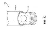
supply tube 600 is shown inFig. 10 .Supply tube 600 includes anouter body 636 and aninner body 638.Outer body 636 maybe formed of the same material as the enclosure.Inner body 638 is formed from a layer of rolled three dimensional material. The three dimensional material aids in preventingsupply tube 600 from kinking or collapsing which may cut off or reduce the air supply to theenclosure 602. In alternative embodiments,supply tube 600 maybe formed from PVC, plastic, or any other conventional tubing material. - In alternative embodiments,
enclosure 602 does not includesupport layer 20. In this embodiment, theopening 612 maybe located nearfoot end 606 or along at least one of the sides of the enclosure. In alternative embodiments,supply tube 600 attaches toenclosure 602 at thehead end 604 or anywhere on the enclosure such as on atop surface 608, abottom surface 610, or on a side surface (not shown) of the enclosure. In certain embodiments,supply tube 600 is integral withenclosure 602. In other embodiments,supply tube 600 attaches to a fitting (not shown). - In other embodiments,
supply tube 600 is split by a T-fitting (not shown) and attaches toenclosure 602 in two or more locations. The supply tube in this embodiment is formed of PVC but may be formed from plastic or any other conventional tubing material. Fig. 12 depicts a bolsterassembly assemblies patient support 10. One or more bolsterassemblies patient support 10 to a particular bed frame configuration, to provide additional support along the edges ofpatient support 10, aid in ingress or egress of a patient frompatient support 10, maintain a patient in the center region ofpatient support 10, or for other reasons. For example, internal air pressure of the bolster bladders maybe higher than the internal bladder pressure ofassembles - Each bolster
assembly combination patient support 10. Each upper and lower bolstercombination cover 138. - In the illustrated embodiment, the bolsters 140, 142 are inflatable bladders. In other embodiments, either or both bolsters 140, 142 maybe constructed of foam, or filled with three-dimensional material, fluid, or other suitable support material. For example, in one embodiment, upper bolster 140 includes two layers of foam: a viscoelastic top layer and a non visco elastic bottom layer, while lower bolster 142 is an inflatable bladder. The bolsters 140, 142 maybe inflated together, or separately, as shown in
Fig. 13 , described below. - Each bolster
combination more support plates 144 which provide support for other components ofpatient support 10 includingvertical bladders 50.Support plates 144 maybe made of a substantially rigid or stiff yet lightweight material such as molded plastic. In other embodiments,plates 144 maybe constructed of stainless steel or steel, if additional weight is desired, i.e. for addition, collapsibility for ease of storage ofpatient support 10, for instance.Support plates 144 maybe provided in order to give support topatient support 10 particularly during transport, for ease of assembly, or for other reasons. - In the illustrated embodiment, each
support plate 144 is a rectangular member extending transversely across the width of themattress 10. As shown in the drawings, there are five such rib-like members 144 spaced apart underneath the head and seat sections of the mattress. In other embodiments, eachsupport plate 144 has its middle section (i.e., the section extending transversely) cut out so that only the two plate ends remain at each spaced-apart end (underneath the bolsters); thereby providing five pairs ofsupport plates 144 spaced apart along the longitudinal length of themattress 10. - Bolster
assembly 86 is similar to bolsterassemblies vertical bladders 50 of longitudinal sections 214, 216. Bolsterassembly 86 has a longitudinally-oriented bladder as its lower bolster portion. - A schematic diagram of the pneumatic control system of
patient support 10 is shown inFig. 13 . ReadingFig. 13 from second to first, there is shown a simplified top view ofpatient support 10 with portions removed to better illustrate thevarious air zones 160, a simplified side view ofpatient support 10, a schematic representation ofpneumatic valve box 58, a schematic representation ofcontrol unit 42, andair lines control unit 42,valve box 58, andair zones 160. - As shown in
Fig. 13 ,air zones 160 ofpatient support 10 are assigned as follows: zone 1 corresponds to headsection bladder assembly 60,zone 2 corresponds to seatsection bladder assembly 62,zone 3 corresponds to footsection bladder assembly 64,zone 4 corresponds to upper side bolsters 140,zone 5 corresponds to lower side bolsters 142,zone 6 corresponds to upper foot bolsters 140, zone 7 corresponds to lower foot bolsters 142,zone 8 corresponds to first turn-assist bladder 74,zone 9 corresponds to second turn-assist bladder 74,zone 10 corresponds todeck filler 90, and zone 11 corresponds to footfiller 80. - An
air line 150 couples eachzone 160 to avalve assembly 162 invalve box 58.Valve box 58 is located in thefoot section 34 ofpatient support 10. Illustratively,valve box 58 is releasably coupled tobottom portion 18 ofcover 12 ininterior region 14, i.e., by one or more Vecro®-brand fasteners or other suitable coupler. - Each
air line 150 is coupled at one end to aninlet port 135 on the corresponding bladder or bladder assembly. Eachair line 150 is coupled at its other end to avalve assembly 162. Eachvalve assembly 162 includes first or fillvalve 163 and a second or ventvalve 165.First valves 163 are coupled toair supply 152 ofcontrol unit 42 byair lines 148.First valves 163 thereby operate to control inflation of the correspondingzone 160 i.e. to fill the zone with air.Second valves 165 operate to at least partially deflate or vent the correspondingzone 160, for example, if the internal air pressure of thezone 160 exceeds a predetermined maximum, or if deflation is necessary or desirable in other circumstances (such as a medical emergency, or for transport of patient support 10). - Each
valve open mode 224 and aclosed mode 226, and a switching mechanism 228 (such as a spring) that switches the value from one mode to another based on control signals fromcontrol unit 42. Inclosed mode 226, air flows fromair supply 152 through thevalue 163 to therespective zone 160 to inflate the corresponding bladders, or in the case ofvent valves 165, from thezone 160 to atmosphere. Inopen mode 228, no inflation or deflation occurs. - In the illustrated embodiment, an
emergency vent valve 230 is provided to enable quick deflation of turningbladders 74 which draws air from atmosphere through afilter 164 and also vents air to atmosphere throughfilter 164.Air supply 152 is an air pump, compressor, blower, or other suitable air source. Air supply 152 is coupled to a switch valve 155 by air line 146.Switch valve 166 operates to control whether inflation or deflation of a zone occurs. An optionalproportional valve 171 maybe coupled toair line 148 to facilitate smooth inflation or deflation of turn-assist bladders 74, or for other reasons.- In the illustrated embodiment,
valve box 58 includes afirst valve module 156 and asecond valve module 158.First valve module 156 includes valves generally associated with a patient's first side (i.e., first side, from the perspective of a patient positioned on patient support 10) andsecond valve module 158 includes valves generally associated with a patient's second side (i.e., second side). - The
various zones 160 are separately inflatable. Certain of thezones 160 are inflated or deflated to allowpatient support 10 to conform to different bed frame configurations. For example, the deck filler 90 (zone 10 in Fig. 23) is inflated to conformpatient support 10 to certain bed frame configurations, such as step deck configurations including the TotalCare® and CareAssist® bed frames, made by Hill-Rom, Inc., the assignee of the present invention, but is deflated whenpatient support 10 is used with a flat deck bed frame, such as the Advanta® bed made by Hill-Rom, Inc. As another example, the foot filler 80 (zone 11 in Fig. 23) is inflated whenpatient support 10 is used with the VersaCare®, TotalCare®, or CareAssist® beds, but the lower side bolsters 142 (zone 5 in Fig. 23) are not inflated whenpatient support 10 is used with a VersaCare® bed. As still another example, the lower foot bolsters 142 (zone 7 in Fig. 23) are inflated whenpatient support 10 is used on flat decks or other bed frames, including the Advanta® and VersaCare® bed frames made by Hill-Rom, Inc. Figs. 11A and11B are a simplified schematic diagram of a control system and the patient support ormattress 10 of the present invention. Fig. 24A illustrates thepatient support 10 including the various components ofpatient support 10 whereas Fig. 24B illustrates thecontrol unit 42 and various components therein. Thepatient support 10 includes thesensor pad 52 which is coupled to the pneumaticvalve control box 58 as previously described. Thesensor pad 52 includes ahead sensor pad 68 and aseat sensor pad 70. Thehead sensor pad 68 is located at thehead end 32 of themattress 10. Theseat sensor pad 70 is located at a middle portion of themattress 10 which is located between thehead end 32 and a location of the pneumaticvalve control box 58. Theseat sensor pad 70 is located such that a patient laying upon themattress 10 may have its middle portion or seat portion located thereon when in a reclined state. In addition, when thehead end 32 of themattress 10 is elevated, the seat portion of the patient is located upon theseat sensor pad 70. As previously described with respect toFig. 3 , thehead sensor pad 68 is located beneath the headsection bladder assembly 60 and theseat sensor pad 70 is located beneath the seatsection bladder assembly 62. Each one of the sensors of thehead sensor pad 68 or theseat sensor pad 70 is located beneath on at least adjacent to one of the upstanding cylindrical bladders or cushions 50. Ahead angle sensor 502 is coupled to thecontrol box 58 where signals received from thesensor 52 may provide head angle information and pressure adjustment information for adjusting pressure in theseat bladders 62.- The
sensor pad 52 is coupled through the associated cabling to thepneumatic control box 58. Thepneumatic control box 58 includes amultiplexer 508 coupled to thehead sensor pad 68 and theseat sensor pad 70 through a signal andcontrol line 510. Themultiplexer board 508 is also coupled to anair control board 512 which is in turn coupled to afirst valve block 514 and asecond valve block 516. A communication/power line 518 is coupled to thecontrol unit 42 ofFig. 11B . Likewise, aventilation supply line 520 which provides for air flow through thepatient support 10 for cooling as well as removing moisture from the patient is also coupled to thecontrol unit 42 ofFig. 11B . An air pressure/vacuum supply line 522 is coupled to thecontrol unit 42 as well. - The
control unit 42 ofFig. 11 B , also illustrated inFig. 1 , includes thedisplay 44, which displays user interface screens, and a userinterface input device 524 for inputting to thecontrol unit 42 user selectable information, such as the selection of various functions or features of the present device. The selections made on the userinterface input device 524 control the operation of thepatient support 10, which can include selectable pressure control of various bladders within themattress 10, control of thedeck 6, for instance to put thebed 2 in a head elevated position, as well as displaying the current state of the mattress or deck position, and other features. - An
algorithm control board 526 is coupled to the userinterface input device 524. Thealgorithm control board 526 receives user generated input signals received through theinput device 524 upon the selection of such functions by the user. Theinput device 524 can include a variety of input devices, such as pressure activated push buttons, a touch screen, as well as voice activated or other device selectable inputs. Thealgorithm control board 526 upon receipt of the various control signals through theuser input device 524 controls not only the operation of themattress 10 but also a variety of other devices which are incorporated into thecontrol unit 42. For instance, thealgorithm control board 526 is coupled to adisplay board 528 which sends signals to thedisplay 44 to which it is coupled. Thedisplay board 528 is also connected to aspeaker 530 which generates audible signals which might indicate the selection of various features at theinput device 24 or indicate a status of a patient positioned on patient support (e.g. exiting) or indicate a status of therapy being provided to the patient (e.g., rotational therapy complete). Thealgorithm control board 526 receives the required power frompower supply 532 which includes anAC input module 534, typically coupled to a wall outlet within a hospital room. - The
algorithm control board 526 is coupled to an air supply, which, in the illustrated embodiment includes acompressor 536 and ablower 538. Both thecompressor 536 and theblower 538 receive control signals generated by thealgorithm control board 526. Thecompressor 536 is used to inflate the air bladders. Theblower 538 is used for air circulation which is provided through theventilation supply line 520 to themattress 10. It is, however, possible that thecompressor 536 maybe used to both inflate the bladders and to circulate the air within themattress 10. A pressure/vacuum switch valve 540 is coupled to thecompressor 536 which is switched to provide for the application of air pressure or a vacuum to themattress 10. Amuffler 541 is coupled to thevalve 540. In the pressure position, air pressure is applied to themattress 10 to inflate the mattress for support of the patient. In the vacuum position, thevalve 540 is used to apply a vacuum to the bladders therein such that the mattress maybe placed in a collapsed state for moving to another location or for providing a CPR function, for example. ACPR button 542 is coupled to thealgorithm control board 526. - As illustrated, the
algorithm control board 526, thecompressor 536, theblower 538, and the user input device oruser control module 524 are located externally to the mattress and are a part of thecontrol unit 42, which maybe located on thefootboard 38 as shown inFig. 1 . The sensors andsensor pad 52, the pneumaticvalve control box 58, and the air control board ormicroprocessor 512 for controlling the valves and thesensor pad system 52 are located within themattress 10. It is within the present scope of the invention to locate some of these devices within different sections of the overall system, for instance, such that thealgorithm control board 526 could be located within themattress 10 or theair control board 512 could be located within thecontrol unit 42. - As shown in
Figs. 14A-14B ,control box 58 includes amultiplexer 252 and anair control board 250.Control board 250 is coupled tomultiplexer 252 by ajumper 254.Multiplexer 252 is further coupled tohead sensor pad 68 andseat sensor pad 70 through a signal and control line (not shown).Control board 250 is also coupled tofirst valve module 156 andsecond valve module 158 by wire leads 251. A communication/power line 258 couples controlboard 250 to thecontrol unit 42.Communication line 258 couples to acommunication plug 259 ofcontrol board 250.Jumper 254 couples multiplexer 252 to controlboard 250 for power and access tocommunication line 258. Wire leads 251 provide actuation power to first andsecond valve modules - As discussed above, first and
second valve modules fill valves 163 and ventvalves 165.First valve module 156 includesfill valves 163a-f and vent valves 165a-f.Second valve module 156 includes fillvalves 163g-l and ventvalves 165g-l. Fillvalves 163a-l and vent valves 165a-l are 12 Volt 7 Watt solenoid direct active poppet style valves in the illustrated embodiment.Control board 252 is able to actuate eachfill valve 163a-l and vent valve 165a-1 independently or simultaneously. Fillvalves 163a-l and vent valves 165a-l are all able to be operated at the same time. In operation to initiate eachvalve control board 250 sends a signal to the valve to be operated. The signal causes a coil (not shown) within each valve to energize for ½ second and then switches to pulsate power (i.e., turn on and off at a high rate) to save power during activation. The activation in turn cause the valve to either open or close depending on which valve is initiated. - Fill
valves 163 are coupled toair supply 152 ofcontrol unit 42 bysecond air line 148.Air line 148 includes an outerbox line assembly 260 and an innerbox line assembly 262. Outerbox line assembly 260 includes anexterior inlet hose 264 and anelbow 266 coupled toexterior inlet hose 264. Innerbox line assembly 262 includes aninterior inlet hose 268 coupled toelbow 266, aunion tee connector 270, afirst module hose 272, and asecond module hose 274.Connector 270 includes a first opening 276 to receiveinterior inlet hose 268, asecond opening 278 to receivefirst module hose 272, and athird opening 280 to receivesecond module hose 274. First andsecond module hoses male coupler 282 to first andsecond valve modules air supply 152 travels throughsupply line 148, enters outerbox line assembly 260 throughexterior inlet hose 264 and passes throughelbow 266 tointerior inlet hose 268. The air then travels frominlet hose 268 tounion tee connector 270 where the air is divided intofirst module hose 272 andsecond module hose 274. The air passes through first andsecond module hoses second valve modules second valve modules Control box 58 includes abase 284, acover 286, and atray 288. Cover 286 includes a plurality of fasteners (i.e., screws) 290.Base 284 includes a plurality of threaded cover posts 292. Cover posts 292 are configured to receivescrews 290 tocouple cover 286 tobase 284. Cover 286 andbase 284 define aninner region 298.Tray 288 couples to base 284 with a plurality ofrivets 291 riveted through a plurality of rivet holes 293 located ontray 288 andbase 284.- Inner
box line assembly 262,first valve module 156,second valve module 158,control board 250, andmultiplexer 252 are contained withininner region 298.Base 284 further includes a plurality of control board posts 294, a plurality ofmultiplexer posts 296, and a plurality of module posts 300. First andsecond valve modules module posts 300 byshoulder screws 302 andwashers 304.Control board 250 andmultiplexer 252 are respectively coupled to controlboard posts 294 andmultiplexer posts 296 by a plurality of snap mounts 306. - First and
second valve modules couplers 308.Couplers 308 include afirst end 310 and asecond end 312. Third air lines 150 a, b, d-f, and g-l each include a fitting (not shown) receivable bysecond end 312. Eachfirst end 310 mounts to aport 314 in first andsecond valve modules First end 310 mounts through a plurality ofopenings 316 inbase 284. - A plurality of
feedback couplers 318 mount through a plurality offeedback openings 320 inbase 284.Feedback couplers 318 include afirst feedback end 322 and asecond feedback end 324. First feedback end 322 couples to a feedback line (not shown) that in turn couples to afeedback port 135 located on eachair zone 160.Second feedback end 324 receives afeedback transfer line 326. Eachtransfer line 326 couples to apressure transducer 328 located on thecontrol board 250.Pressure transducer 328 receives the pressure from eachair zone 160 and transmits to control unit 42 a pressure data signal representing the internal air pressure of thezone 160.Control unit 42 uses these pressure signals to determine the appropriate pressures for certain mattress functions such as CPR, patient transfer, and max-inflate. Pressure signals from thetransducer 328 coupled to the foot zone 160k are also used to maintain optimal pressure in foot zone 160k. In the illustrated embodiment, pressure in foot zone 160k (zone 3) is computed as a percentage of the pressure in seat zone 160e (zone 2). The pressures in seat zone 160e and head zone 160f are determined using both thetranducers 328 and the pressure sensors 136. The pressures in one or more of thezones 160 maybe adjusted in real time. - As shown in
Fig. 13 , fillvalves 163a-l and vent valves 165a-l are coupled to various portions ofpatient support 10 through third air lines 150 a, b, d-f, and g-l. Fillvalve 163a and vent valve 165a are coupled to upper foot bolsters 140c, fillvalve 163b and ventvalve 165b are coupled to lower side bolsters 142 a, b, fillvalve 163c is coupled to atmosphere and ventvalve 165c is reserved for future therapies. Also, fillvalve 163d and ventvalve 165d are coupled to first turn assist 74a, fillvalve 163e and ventvalve 165e are coupled toseat bladders 62, fillvalve 163f and ventvalve 165f are coupled to headbladder assembly 60, fillvalve 163g and ventvalve 165g are coupled tofoot filler 80, fillvalve 163h and ventvalve 165h are coupled to upper side bolsters 140 a, b, fill valve 163i and vent valve 165i are coupled todeck filler 90, fillvalve 163j and ventvalve 165j are coupled to first turn assist 74b, fillvalve 163k and ventvalve 165k are coupled to footbladders 164, fillvalve 1631 and ventvalve 1651 are coupled to lower foot bolsters 142c.Vent valves 165d, j are biased in the open position to vent air from first and second turn assist 74a, 74b when first and second turn assist 74a, 74b are not in use.Vent valves 165d, j return to their open position if the mattress loses power or pressure venting air from the first and second turn assist 74a, 74b. When air is vented from azone 160, the pressure in thezone 160 after deflation is determined by thecontrol system - In one embodiment, a user enters an input command to control
unit 42.Control unit 42 processes the input command and transmits a control signal based on the input command throughcommunication line 258 to controlboard 250. Additionally or alternatively, control signals could be based on operational information fromcontrol unit 42 to increase or decrease pressure within one or more of thezones 160 based on information obtained fromtransducers 328 and/or sensors 136. - It should be noted that in the illustrated embodiment, the mattress controls 42, 58 are independent from operation of the
bed frame 4. In other embodiments, however,bed frame 4 andmattress 10 maybe configured to exchange or share data through communication lines. For instance, data is communicated frombed frame 4 tomattress system mattress 10. For instance, in one embodiment, a signal is transmitted fromframe 4 whenfoot section 34 is retracting, so thatmattress systems vertical bladders 50 infoot assembly 64. - As described above,
air supply 152 is capable of supplying air or acting as a vacuum to remove air fromzones 160. While in supply mode, a microprocessor oncontrol board 250 actuates correspondingfill valve 163a-l or vent valve 165a-l based on the control signal fromcontrol unit 42. For example, if the control signal indicates the pressure inhead bladder assembly 160 is to be increasedfill valve 163f is actuated. However, if the control signal indicates the pressure inhead bladder assembly 160 is to be decreasedvent valve 165f is actuated. While in vacuum mode one ormore fill valves 163a-l maybe actuated to allow for rapid removal of air within the corresponding zones. - An
angle sensor cable 256 is provided to send a signal from ahead angle sensor 502 to thecontrol board 250.Angle sensor cable 256 couples to anangle plug 257 ofcontrol board 250. In the illustrated embodiment,head angle sensor 502 is located within head bolsterassembly 76 as indicated byFigs. 11A and15 .Head angle sensor 502 indicates the angle of elevation of thehead end 32 ofbed 2 as the head section of theframe 4 articulates upwardly raising the patient's head or downwardly lowering the patient's head. In one embodiment,angle sensor 502 transmits the angle ofhead end 32 to all nodes or circuit boards within themattress control system Angle sensor 502 generates an indication or indicator signal whenhead end 32 is at an angle of at least 5°, at least 30°, and at least 45°. The head angle indication is transmitted to thecontrol unit 42 which evaluates and processes the signal. Whenhead end 32 is at an angle above 30° turn assist 74 becomes inoperative primarily for patient safety reasons. Whenhead end 32 is at an angle above 45° information is transmitted to controlunit 42 for use in the algorithms. The 5° angle indication is primarily to ensure relative flatness ofpatient support 10. In the illustrated embodiment,angle sensor 502 is a ball switch. In an alternative embodiment,angle sensor 502 maybe a string potentiometer. - As shown in
Figs. 16A-16C , threeballs angle sensor 502.First ball 702 actuates when thehead end 32 is at an angle of at least 5° movingfirst ball 702 from afirst position 708 to asecond position 710.Second ball 704 indicates when thehead end 32 is at an angle of at least 30° movingsecond ball 704 from afirst position 712 to asecond position 714.Third ball 706 indicates when thehead end 32 is at an angle of at least 45° movingthird ball 706 from afirst position 716 to asecond position 718. Fig. 17 showspatient support 10 in a transportation position on apallet 750. As discussed above,air supply 42 is capable of providing a vacuum to evacuate the air from withinpatient support 10. This allowspatient support 10 to be folded. As shown inFig. 17 ,couplers 46 holdpatient support 10 in the transportation position.Support plates 144 are provided as separate plates to aid in the folding process. Aspatient support 10 is folded, any remaining air not evacuated by theair supply 42 is forced from thepatient support 10.- In
Fig. 18 , a side view of another embodiment of a patient support 10 (not in accord with the invention) is shown with anenclosure 602.Enclosure 602 includes atop surface 608, a fire-resistant material 16 beneath thetop surface 608, and a three-dimensional layer 20 beneath the fire-resistant material 16. The three-dimensional layer 20 includes atop membrane layer 220 and abottom membrane layer 222. Thetop membrane layer 220 andbottom membrane layer 222 can be impermeable to air and the three-dimensional material 20 can include Spacenet, Tytex, and/or similar material, as disclosed inFigs. 4 and9 and corresponding descriptions, for example. One or moreinflatable bladders 50 are provided as an additional support layer beneath thebottom membrane layer 222. At thefoot end 34 of thepatient support 10, apneumatic box 58 and anadditional layer 84, are provided.Layer 84 includes a retractable foam material in the illustrated embodiment. - As illustrated in
Figs. 18 and 19 , air is supplied by an air supply (not shown) through asupply tube 600 located near oneend 34 of thepatient support 10. Thesupply tube 600 is coupled to a fitting 700 which also attaches to distributingtubes 800. This arrangement is further shown inFig. 20 and described below. Air flows through the distributingtubes 800 and into theenclosure 602 in adirection 660 from the oneend 34 to theother end 32 of thepatient support 10. The air can be released from theenclosure 602 by avent assembly 662 near theend 32 of thepatient support 10. In the illustrated embodiment, air flows from the foot end of the head end of the patient support. In other embodiments, air may flow in the reverse direction or laterally across the patient support. - In
Fig. 20 , another embodiment for supplying air to theenclosure 602 is shown including asupply tube 600, fitting 700, and distributingtubes 800. Air is received by asupply tube 600 and is transported into distributingtubes 800. Thesupply tube 600 and distributingtubes 800 are attached by a fitting 700. The fitting 700 can be a T-fitting, as shown inFig. 20 , or any other type of suitable fitting known in the art. Air flows through the distributingtubes 800 and into theenclosure 602. - Another embodiment of the
supply tube 600, fitting 700, and distributingtubes 800 arrangement is shown inFigs. 21 and22 including acloth manifold arrangement 810. Thecloth manifold arrangement 810 includes acloth manifold 820 made of anouter layer material 822 that can be impermeable to air. Thecloth manifold 820 is a soft material that provides additional comfort to the patient and includes a receivingportion 824 and a plurality of distributingportions 826. The receivingportion 824 can attach to a flow tube (not shown) or directly to an air supply (not shown). The distributingportions 826 are coupled to theenclosure 602 by one or more Velcro®-brand strips or similar fasteners 828. The distributingportions 826 may also include hollow receivingapertures 832 used for additional fastening the distributingportions 826 to theenclosure 602. Thecloth manifold 820 may include aninner layer 830, as shown inFig. 22 , made from three-dimensional material 20 such as Spacenet, Tytex, and/or similar material as described above. Theinner layer 830 may be configured to help prevent thecloth manifold 820 from kinking or collapsing which may cut off or reduce the air supply to theenclosure 602. - The present invention has been described with reference to certain exemplary embodiments, variations, and applications. However, the present invention is not limited by the described embodiments, variations, and applications, but by the appended claims.
Claims (15)
- A patient support comprising a body including a bladder (50), and an air loss device (91) including a tube (92, 94), wherein the tube (92, 94) receives a volume of air from an air supply, the tube (92, 94) including a plurality of apertures (93) configured to deliver the air received,characterized in that the support further comprises a cover (12), the body located within the cover (12) and the air being delivered across the bladder (50) within the cover (12).
- The patient support of claim 1, wherein the body includes a plurality of bladders (50).
- The patient support of claim 2, wherein the plurality of bladders are vertical bladders (50).
- The patient support of either claim 1, claim 2 or claim 3, further comprising a three dimensional fiber network material layer (27 - 30), located above the plurality of bladders (50).
- The patient support of claim 4, further comprising a first layer (28) of an air-permeable three-dimensional material and a second layer (30) of the air-permeable three-dimensional material, the three-dimensional material having a network of thermoplastic fibers.
- The patient support of claim 5, wherein the first layer (28) includes a plurality of dome-shaped projections (22) and is positioned above the second layer (30), the dome-shaped projections (22) of the first layer (28) projecting upwardly away from the second layer (30).
- The patient support of claim 6, wherein the second layer (30) includes a plurality of dome-shaped projections (22) and is positioned below the first layer (28), the dome-shaped projections (22) of the second layer (30) projecting downwardly away from the first layer (28).
- The patient support of any one of claims 4 to 7, wherein the three dimensional fiber network material is air permeable.
- The patient support of any preceding claim, wherein the tube includes a supply tube (92) and a delivery tube (94).
- The patient support of claim 9, wherein the supply tube (92) receives a volume of low pressure air from the air supply, and the delivery tube (94) includes a plurality of apertures (93) configured to vent the air received from the supply tube around the plurality of bladders.
- The patient support of claim 10, wherein the delivery tube (94) is located between a seat section and a foot section of the body.
- The patient support of any of claims 5 to 7, wherein the cover (12) is vapor permeable and air impermeable.
- The patient support of any preceding claim, wherein the air supply is configured to supply a first pressure and volume of air to the bladder and a second volume of pressure of air to the air loss device.
- The patient support of claim 13, wherein the first pressure is greater than the second pressure.
- The patient support of either of claim 13 or claim 14, wherein the first volume is less than the second volume.
Applications Claiming Priority (2)
| Application Number | Priority Date | Filing Date | Title |
|---|---|---|---|
| US69772305P | 2005-07-08 | 2005-07-08 | |
| PCT/US2006/026620WO2007008723A2 (en) | 2005-07-08 | 2006-07-07 | Patient support |
Publications (3)
| Publication Number | Publication Date |
|---|---|
| EP1901635A2 EP1901635A2 (en) | 2008-03-26 |
| EP1901635A4 EP1901635A4 (en) | 2011-12-07 |
| EP1901635B1true EP1901635B1 (en) | 2013-05-01 |
Family
ID=37637805
Family Applications (1)
| Application Number | Title | Priority Date | Filing Date |
|---|---|---|---|
| EP06786689.7AActiveEP1901635B1 (en) | 2005-07-08 | 2006-07-07 | Patient support |
Country Status (5)
| Country | Link |
|---|---|
| US (2) | US9707141B2 (en) |
| EP (1) | EP1901635B1 (en) |
| JP (1) | JP2009500128A (en) |
| AU (1) | AU2006269277B2 (en) |
| WO (1) | WO2007008723A2 (en) |
Cited By (1)
| Publication number | Priority date | Publication date | Assignee | Title |
|---|---|---|---|---|
| US10238560B2 (en) | 2013-03-13 | 2019-03-26 | Hill-Rom Services, Inc. | Air fluidized therapy bed having pulmonary therapy |
Families Citing this family (61)
| Publication number | Priority date | Publication date | Assignee | Title |
|---|---|---|---|---|
| EP1076499B1 (en)* | 1998-05-06 | 2004-07-21 | Hill-Rom Services, Inc. | Mattress or cushion structure |
| US9462893B2 (en) | 1998-05-06 | 2016-10-11 | Hill-Rom Services, Inc. | Cover system for a patient support surface |
| US7469436B2 (en)* | 2004-04-30 | 2008-12-30 | Hill-Rom Services, Inc. | Pressure relief surface |
| EP1901635B1 (en) | 2005-07-08 | 2013-05-01 | Hill-Rom Services, Inc. | Patient support |
| US8117701B2 (en) | 2005-07-08 | 2012-02-21 | Hill-Rom Services, Inc. | Control unit for patient support |
| WO2007075699A2 (en)* | 2005-12-19 | 2007-07-05 | Stryker Corporation | Hospital bed |
| US8856993B2 (en)* | 2008-04-15 | 2014-10-14 | Hill-Rom Services, Inc. | Temperature and moisture regulating topper for non-powered person-support surfaces |
| US8490226B2 (en) | 2008-09-19 | 2013-07-23 | Diacor, Inc. | Systems for patient transfer, devices for movement of a patient, and methods for transferring a patient for treatment |
| US8437876B2 (en) | 2009-08-07 | 2013-05-07 | Hill-Rom Services, Inc. | Patient health based support apparatus configuration |
| US8531307B2 (en)* | 2009-09-18 | 2013-09-10 | Hill-Rom Services, Inc. | Patient support surface index control |
| US8677536B2 (en)* | 2009-11-18 | 2014-03-25 | Hill-Rom Services, Inc. | Method and apparatus for sensing foot retraction in a mattress replacement system |
| US9820904B2 (en) | 2011-07-13 | 2017-11-21 | Stryker Corporation | Patient/invalid handling support |
| WO2011097569A2 (en)* | 2010-02-05 | 2011-08-11 | Stryker Corporation | Patient/invalid handling support |
| US9044367B2 (en) | 2010-06-12 | 2015-06-02 | American Home Health Care, Inc. | Patient weighing and bed exit monitoring |
| USD690424S1 (en) | 2011-01-26 | 2013-09-24 | Sage Products, Inc. | Set of components for a patient repositioning system |
| US11039962B2 (en) | 2012-04-02 | 2021-06-22 | TurnCare, Inc. | Non-invasive pressure-mitigation apparatuses for improving blood flow and associated systems and methods |
| US20130255699A1 (en) | 2012-04-02 | 2013-10-03 | TurnCare, Inc. | Patient-orienting alternating pressure decubitus prevention support apparatus |
| US9138064B2 (en)* | 2013-01-18 | 2015-09-22 | Fxi, Inc. | Mattress with combination of pressure redistribution and internal air flow guides |
| US9433300B2 (en) | 2013-02-28 | 2016-09-06 | Hill-Rom Services, Inc. | Topper for a patient surface |
| US9333136B2 (en) | 2013-02-28 | 2016-05-10 | Hill-Rom Services, Inc. | Sensors in a mattress cover |
| US9782312B2 (en) | 2013-09-05 | 2017-10-10 | Stryker Corporation | Patient support |
| US20150342805A1 (en)* | 2014-04-08 | 2015-12-03 | Harris Medical, Llc | Mobile transportation device convertible to a trendelenburg table and for use in a motor vehicle and method thereof |
| US20150283017A1 (en)* | 2014-04-08 | 2015-10-08 | Harris Medical, Llc | Mobile transportation device convertible to an examination table and for use in a motor vehicle and method thereof |
| US9504620B2 (en)* | 2014-07-23 | 2016-11-29 | American Sterilizer Company | Method of controlling a pressurized mattress system for a support structure |
| US10045715B2 (en) | 2015-04-27 | 2018-08-14 | Hill-Rom Services, Inc. | Self-compensating bed scale system for removable components |
| US10054479B2 (en) | 2015-05-05 | 2018-08-21 | Hill-Rom Services, Inc. | Bed with automatic weight offset detection and modification |
| US10765577B2 (en) | 2015-06-30 | 2020-09-08 | Hill-Rom Services, Inc. | Microclimate system for a patient support apparatus |
| US10512301B2 (en)* | 2015-08-06 | 2019-12-24 | Nike, Inc. | Cushioning assembly for an article of footwear |
| EP3205268B1 (en) | 2016-02-11 | 2023-10-25 | Hill-Rom Services, Inc. | Hospital bed |
| WO2019036329A1 (en) | 2017-08-16 | 2019-02-21 | Covidien Lp | Operating table for robotic surgical systems |
| US11173085B2 (en) | 2017-12-28 | 2021-11-16 | Stryker Corporation | Mattress cover for a mattress providing rotation therapy to a patient |
| US11246775B2 (en) | 2017-12-28 | 2022-02-15 | Stryker Corporation | Patient turning device for a patient support apparatus |
| US11253079B1 (en) | 2018-03-26 | 2022-02-22 | Dp Technologies, Inc. | Multi-zone adjustable bed with smart adjustment mechanism |
| US20200037779A1 (en)* | 2018-07-31 | 2020-02-06 | Levy Zur | Area support surface seating system |
| US11458052B2 (en) | 2018-08-01 | 2022-10-04 | Hill-Rom Services, Inc. | Skin injury resistant occupant support structures and methods for resisting skin injuries |
| USD879966S1 (en) | 2018-09-28 | 2020-03-31 | Stryker Corporation | Crib assembly |
| USD977109S1 (en) | 2018-09-28 | 2023-01-31 | Stryker Corporation | Crib assembly for a patient support |
| USD901940S1 (en) | 2018-09-28 | 2020-11-17 | Stryker Corporation | Patient support |
| USD888963S1 (en) | 2018-09-28 | 2020-06-30 | Stryker Corporation | Cover assembly for a patient support |
| USD888962S1 (en) | 2018-09-28 | 2020-06-30 | Stryker Corporation | Cover assembly for a patient support |
| USD888964S1 (en) | 2018-09-28 | 2020-06-30 | Stryker Corporation | Crib assembly for a patient support |
| USD877915S1 (en) | 2018-09-28 | 2020-03-10 | Stryker Corporation | Crib assembly |
| USD894956S1 (en) | 2018-10-31 | 2020-09-01 | Stryker Corporation | Display screen or portion thereof with graphical user interface |
| USD890914S1 (en) | 2018-10-31 | 2020-07-21 | Stryker Corporation | Pump |
| USD893543S1 (en) | 2018-10-31 | 2020-08-18 | Stryker Corporation | Display screen with graphical user interface |
| USD894226S1 (en) | 2018-10-31 | 2020-08-25 | Stryker Corporation | Display screen or portion thereof with graphical user interface |
| USD894957S1 (en) | 2018-10-31 | 2020-09-01 | Stryker Corporation | Display screen or portion thereof with graphical user interface |
| USD894223S1 (en) | 2018-10-31 | 2020-08-25 | Stryker Corporation | Display screen with animated graphical user interface |
| USD892159S1 (en) | 2018-10-31 | 2020-08-04 | Stryker Corporation | Display screen with animated graphical user interface |
| US12150905B2 (en) | 2018-11-27 | 2024-11-26 | Stryker Corporation | Patient support apparatus with notification system |
| CA3085438A1 (en) | 2019-08-13 | 2021-02-13 | Stryker Corporation | Support apparatus for bariatric person |
| DE102019124452A1 (en) | 2019-09-11 | 2021-03-11 | Emma Sleep Gmbh | Bed component and bed |
| US12016812B2 (en) | 2020-10-09 | 2024-06-25 | TurnCare, Inc. | Pressure-mitigation apparatuses for improved treatment of respiratory illnesses and associated systems and methods |
| US12178949B2 (en) | 2020-10-09 | 2024-12-31 | TurnCare, Inc. | Pressure-mitigation apparatuses for improved treatment of immobilized patients and associated systems and methods |
| CN112842749B (en)* | 2021-02-20 | 2022-04-12 | 新乡医学院第一附属医院 | A back pressure ulcer care device |
| EP4062885A1 (en)* | 2021-03-26 | 2022-09-28 | Hill-Rom Services, Inc. | Person support systems including separately selectable alternating pressure zones |
| USD992946S1 (en)* | 2021-05-07 | 2023-07-25 | Tanya Ann Wiese | ICU bed extension for proning |
| US12290484B2 (en)* | 2021-06-30 | 2025-05-06 | Hill-Rom Services, Inc. | Manifold assembly for pneumatic system |
| US12337738B2 (en) | 2022-11-09 | 2025-06-24 | Lear Corporation | Fluid system for a vehicle seat assembly |
| WO2023244763A2 (en)* | 2022-06-16 | 2023-12-21 | Lear Corporation | Vehicle seat assembly and subassemblies thereof |
| US12326742B2 (en)* | 2022-12-22 | 2025-06-10 | Lear Corporation | Valve and actuator assembly for a fluid system in a vehicle seat assembly |
Family Cites Families (166)
| Publication number | Priority date | Publication date | Assignee | Title |
|---|---|---|---|---|
| US779576A (en)* | 1903-09-11 | 1905-01-10 | Benjamin F Berryman | Mattress. |
| US800967A (en) | 1904-10-20 | 1905-10-03 | George S Tolman | Pneumatic mattress, &c. |
| US1121277A (en) | 1913-12-04 | 1914-12-15 | Theresa C Mitchell | Warming appliance for beds. |
| US1332933A (en)* | 1916-05-12 | 1920-03-09 | Rubber Regenerating Co | Pneumatic cushion |
| GB159299A (en) | 1919-11-22 | 1921-02-22 | Charles Reginald Stone | Air- and water-mattresses and the like |
| US1772310A (en)* | 1926-12-16 | 1930-08-05 | Julian D Hart | Variable-pressure bed or mattress |
| GB969367A (en)* | 1962-03-05 | 1964-09-09 | George Ingram | Improvements in inflatable mattresses, pillows and cushions |
| US3492988A (en)* | 1967-09-01 | 1970-02-03 | Baltzar Leo De Mare | Pneumatic positioner |
| AU458068B2 (en) | 1971-02-05 | 1975-01-30 | YAT CHUEN YUEN and KIN SUN YUEN | Inflatable mattresses and cushions |
| US3978530A (en)* | 1975-11-21 | 1976-09-07 | Amarantos John G | Air inflatable bed-like device with adjustable back support |
| US4114620A (en)* | 1977-03-02 | 1978-09-19 | Moore-Perk Corporation | Patient treatment pad for hot or cold use |
| GB2070174A (en)* | 1980-02-26 | 1981-09-03 | Watkins & Watson Ltd | Conduit connector |
| US4347633A (en)* | 1980-07-22 | 1982-09-07 | American Hospital Supply Corporation | Patient treating mattress |
| US4448228A (en) | 1981-01-09 | 1984-05-15 | Aisin Seiki Kabushiki Kaisha | Air bag system having a branched joint |
| US4483029A (en) | 1981-08-10 | 1984-11-20 | Support Systems International, Inc. | Fluidized supporting apparatus |
| US4477935A (en) | 1982-01-08 | 1984-10-23 | Griffin Gordon D | Mattress support system |
| US4527298A (en)* | 1982-03-18 | 1985-07-09 | Moulton Lee A | Electro pneumatic bed |
| JPS5993524U (en)* | 1982-12-15 | 1984-06-25 | 狩野 千世子 | Air mat type bed operated by computer |
| US4541135A (en)* | 1984-04-16 | 1985-09-17 | Victor Karpov | Air mattress |
| US4606087A (en)* | 1984-09-14 | 1986-08-19 | Alivizatos Margaret A | Convertible body supporting pads |
| GB2167293B (en) | 1984-11-26 | 1988-12-07 | Matsushita Electric Works Ltd | Bedsore preventing apparatus |
| US4637083A (en)* | 1985-03-13 | 1987-01-20 | Support Systems International, Inc. | Fluidized patient support apparatus |
| US4638519A (en)* | 1985-04-04 | 1987-01-27 | Air Plus, Inc. | Fluidized hospital bed |
| JPS61290953A (en)* | 1985-06-19 | 1986-12-20 | 富士電機株式会社 | body support equipment |
| US5051673A (en)* | 1985-12-30 | 1991-09-24 | Goodwin Vernon L | Patient support structure |
| FR2596950B1 (en) | 1986-04-11 | 1988-11-18 | Huneau Jacques | MONITORING DEVICE FOR MONITORING MOBILE DISCRETE ELEMENTS, MONITORING SYSTEM COMPRISING SUCH DEVICES AND THEIR USE IN STABLE MANAGEMENT |
| US4797962A (en)* | 1986-11-05 | 1989-01-17 | Air Plus, Inc. | Closed loop feedback air supply for air support beds |
| GB2199803B (en)* | 1987-01-20 | 1991-05-29 | Sanwa Shutter Corp | Elevation bed |
| US4839512A (en)* | 1987-01-27 | 1989-06-13 | Tactilitics, Inc. | Tactile sensing method and apparatus having grids as a means to detect a physical parameter |
| JPS63305864A (en)* | 1987-06-05 | 1988-12-13 | Matsushita Electric Works Ltd | Controller for bedsore preventing mat |
| JPH0344187Y2 (en)* | 1987-11-10 | 1991-09-17 | ||
| US4953244A (en)* | 1987-12-28 | 1990-09-04 | Hill-Rom Company, Inc. | Hospital bed for weighing patients |
| US4934468A (en)* | 1987-12-28 | 1990-06-19 | Hill-Rom Company, Inc. | Hospital bed for weighing patients |
| GB8805961D0 (en)* | 1988-03-14 | 1988-04-13 | Huntleigh Technology Plc | Pressure controller |
| US4884304A (en) | 1988-09-28 | 1989-12-05 | Life Support Systems, Inc. | Bedding system with selective heating and cooling |
| US4907308A (en)* | 1988-11-21 | 1990-03-13 | Kinetic Concepts, Inc. | Heat exchange system for inflatable patient support appliances |
| US4942635A (en) | 1988-12-20 | 1990-07-24 | Ssi Medical Services, Inc. | Dual mode patient support system |
| US5029352A (en)* | 1988-12-20 | 1991-07-09 | Ssi Medical Services, Inc. | Dual support surface patient support |
| SE465702B (en)* | 1989-01-03 | 1991-10-21 | Irene Kaufmann | SUBSTANCES WITH INDIVIDUALLY VALVE FILLABLE EVACUABLE FLEXIBLE CELL BODIES |
| US5140306A (en)* | 1989-01-04 | 1992-08-18 | Hemphill Sr Francis A | Alarm indicating system |
| US4944060A (en)* | 1989-03-03 | 1990-07-31 | Peery John R | Mattress assembly for the prevention and treatment of decubitus ulcers |
| US4993920A (en)* | 1989-04-07 | 1991-02-19 | Harkleroad Barry A | Air mattress pumping and venting system |
| US5168589A (en) | 1989-04-17 | 1992-12-08 | Kinetic Concepts, Inc. | Pressure reduction air mattress and overlay |
| US4951335A (en)* | 1989-06-05 | 1990-08-28 | Donan Marketing Corporation | Mattress assembly |
| US5020176A (en)* | 1989-10-20 | 1991-06-04 | Angel Echevarria Co., Inc. | Control system for fluid-filled beds |
| US5444881A (en)* | 1989-12-04 | 1995-08-29 | Supracor Systems, Inc. | Anatomical support apparatus |
| US5180619A (en)* | 1989-12-04 | 1993-01-19 | Supracor Systems, Inc. | Perforated honeycomb |
| US5840400A (en) | 1989-12-04 | 1998-11-24 | Supracor Systems, Inc. | Perforated core honeycomb panel system |
| US5067189A (en) | 1990-04-11 | 1991-11-26 | Weedling Robert E | Air chamber type patient mover air pallet with multiple control features |
| US5060174A (en) | 1990-04-18 | 1991-10-22 | Biomechanics Corporation Of America | Method and apparatus for evaluating a load bearing surface such as a seat |
| US5483709A (en)* | 1994-04-01 | 1996-01-16 | Hill-Rom Company, Inc. | Low air loss mattress with rigid internal bladder and lower air pallet |
| US5163196A (en) | 1990-11-01 | 1992-11-17 | Roho, Inc. | Zoned cellular cushion with flexible flaps containing inflating manifold |
| US5184122A (en)* | 1991-01-31 | 1993-02-02 | Johnson Service Company | Facility management system with improved return to automatic control |
| US5289030A (en)* | 1991-03-06 | 1994-02-22 | Semiconductor Energy Laboratory Co., Ltd. | Semiconductor device with oxide layer |
| US5364162A (en) | 1991-03-01 | 1994-11-15 | Roho, Inc. | Backrest assembly for a wheelchair |
| US5140309A (en) | 1991-03-12 | 1992-08-18 | Gaymar Industries, Inc. | Bed signalling apparatus |
| US5269030A (en) | 1991-11-13 | 1993-12-14 | Ssi Medical Services, Inc. | Apparatus and method for managing waste from patient care, maintenance, and treatment |
| US5276432A (en)* | 1992-01-15 | 1994-01-04 | Stryker Corporation | Patient exit detection mechanism for hospital bed |
| US5561875A (en)* | 1992-02-20 | 1996-10-08 | Crown Therapeutics, Inc. | Vacuum/heat formed cushion supported on a fluid permeable manifold |
| US5325551A (en)* | 1992-06-16 | 1994-07-05 | Stryker Corporation | Mattress for retarding development of decubitus ulcers |
| US5317767A (en)* | 1992-06-16 | 1994-06-07 | Hargest Thomas S | Sudden infant death syndrome prevention apparatus and method |
| US5267364A (en) | 1992-08-11 | 1993-12-07 | Kinetic Concepts, Inc. | Therapeutic wave mattress |
| US5316041A (en)* | 1992-10-27 | 1994-05-31 | Colder Product Company | Quick connection coupling valve assembly |
| DE69318848T2 (en) | 1992-10-29 | 1998-09-24 | Geomarine Systems Inc | SYSTEM AND METHOD FOR A MATTRESS FOR TREATMENT BY SIDE TURNING |
| US5373595A (en) | 1993-03-12 | 1994-12-20 | Irvin Industries Canada Ltd. | Air support device |
| US5402542A (en)* | 1993-04-22 | 1995-04-04 | Ssi Medical Services, Inc. | Fluidized patient support with improved temperature control |
| US5350417A (en)* | 1993-05-18 | 1994-09-27 | Augustine Medical, Inc. | Convective thermal blanket |
| US5592706A (en) | 1993-11-09 | 1997-01-14 | Teksource, Lc | Cushioning device formed from separate reshapable cells |
| US5539942A (en)* | 1993-12-17 | 1996-07-30 | Melou; Yves | Continuous airflow patient support with automatic pressure adjustment |
| US5715548A (en)* | 1994-01-25 | 1998-02-10 | Hill-Rom, Inc. | Chair bed |
| US5586346A (en) | 1994-02-15 | 1996-12-24 | Support Systems, International | Method and apparatus for supporting and for supplying therapy to a patient |
| US5448788A (en)* | 1994-03-08 | 1995-09-12 | Wu; Shuenn-Jenq | Thermoelectric cooling-heating mattress |
| US5611096A (en)* | 1994-05-09 | 1997-03-18 | Kinetic Concepts, Inc. | Positional feedback system for medical mattress systems |
| GB9410489D0 (en)* | 1994-05-25 | 1994-07-13 | Egerton Hospital Equip | Improvements in and relating to low air-loss mattresses |
| US5787531A (en)* | 1994-07-08 | 1998-08-04 | Pepe; Michael Francis | Inflatable pad or mattress |
| US5561873A (en) | 1994-07-15 | 1996-10-08 | Patient Transfer Systems, Inc. | Air chamber-type patient mover air pallet with multiple control features |
| US5542136A (en)* | 1994-08-05 | 1996-08-06 | Stryker Corporation | Portable mattress for treating decubitus ulcers |
| US5623736A (en)* | 1994-12-09 | 1997-04-29 | Suport Systems, International | Modular inflatable/air fluidized bed |
| DE29502025U1 (en) | 1995-02-08 | 1996-06-05 | Dreher, Herbert, Creutzwald | Changeable pillow |
| DK0821559T3 (en) | 1995-04-25 | 2003-10-06 | Kinetic Concepts Inc | Airbed with fluidized bead surface and associated methods |
| US6721979B1 (en)* | 1995-04-25 | 2004-04-20 | Kci Licensing, Inc. | Air bed with fluidized bead surface and related methods |
| US5564142A (en) | 1995-05-11 | 1996-10-15 | Liu; Tsung-Hsi | Air mattress collaboratively cushioned with pulsative and static symbiotic sacs |
| US5634225A (en)* | 1995-05-25 | 1997-06-03 | Foamex L.P. | Modular air bed |
| US6014208A (en)* | 1995-07-24 | 2000-01-11 | Gersan Establishment | Examining a diamond |
| US6499167B1 (en) | 1995-08-04 | 2002-12-31 | Hill-Rom Services, Inc. | Mattress section support |
| US5692256A (en) | 1995-08-04 | 1997-12-02 | Hill-Rom, Inc. | Mattress for a hospital bed |
| US5630238A (en)* | 1995-08-04 | 1997-05-20 | Hill-Rom, Inc. | Bed with a plurality of air therapy devices, having control modules and an electrical communication network |
| US5991949A (en) | 1995-08-15 | 1999-11-30 | Foamex L.P. | Hoseless air bed |
| US5815865A (en) | 1995-11-30 | 1998-10-06 | Sleep Options, Inc. | Mattress structure |
| US5731062A (en)* | 1995-12-22 | 1998-03-24 | Hoechst Celanese Corp | Thermoplastic three-dimensional fiber network |
| US5815864A (en) | 1996-04-02 | 1998-10-06 | Sytron Corporation | Microprocessor controller and method of initializing and controlling low air loss floatation mattress |
| US5689845A (en) | 1996-04-17 | 1997-11-25 | Roho, Inc. | Expansible air cell cushion |
| US5785716A (en) | 1996-05-09 | 1998-07-28 | Bayron; Harry | Temperature control pad for use during medical and surgical procedures |
| GB9610233D0 (en)* | 1996-05-16 | 1996-07-24 | Kci Medical Ltd | Mattress cooling system |
| US5794288A (en) | 1996-06-14 | 1998-08-18 | Hill-Rom, Inc. | Pressure control assembly for an air mattress |
| US5699570A (en) | 1996-06-14 | 1997-12-23 | Span-America Medical Systems, Inc. | Pressure relief valve vent line mattress system and method |
| US5873137A (en)* | 1996-06-17 | 1999-02-23 | Medogar Technologies | Pnuematic mattress systems |
| USD386035S (en) | 1996-07-12 | 1997-11-11 | Roho, Inc. | Cushion |
| USD439098S1 (en) | 1996-07-12 | 2001-03-20 | Roho, Inc. | Cushion seating area |
| US5845352A (en) | 1996-07-12 | 1998-12-08 | Roho, Inc. | Foam-air hybrid cushion and method of making same |
| FR2751530B1 (en)* | 1996-07-23 | 1998-10-23 | Support Systems International | METHOD AND DEVICE FOR SUPPORTING A PATIENT WITH A DERIVED SUPPORT HEEL AREA |
| US5966763A (en)* | 1996-08-02 | 1999-10-19 | Hill-Rom, Inc. | Surface pad system for a surgical table |
| US5989285A (en) | 1996-08-15 | 1999-11-23 | Thermotek, Inc. | Temperature controlled blankets and bedding assemblies |
| US5970789A (en) | 1996-11-20 | 1999-10-26 | Hill-Rom, Inc. | Method and apparatus for evaluating a support surface |
| GB9626860D0 (en) | 1996-12-24 | 1997-02-12 | Pegasus Airwave Ltd | Patient movement detection |
| US5984418A (en) | 1997-04-28 | 1999-11-16 | Crown Therapeutics, Inc. | Adjustable seat for wheelchairs |
| US5954402A (en) | 1997-04-28 | 1999-09-21 | Crown Therapeutics, Inc. | Size-adjustable load supporting device for wheelchairs |
| US5787716A (en)* | 1997-06-13 | 1998-08-04 | Allen, Jr.; Russel G. | Dry ice sublimation cooling system utilizing a vacuum |
| US6076208A (en)* | 1997-07-14 | 2000-06-20 | Hill-Rom, Inc. | Surgical stretcher |
| US5917180A (en)* | 1997-07-16 | 1999-06-29 | Canadian Space Agency | Pressure sensor based on illumination of a deformable integrating cavity |
| FR2766072B1 (en) | 1997-07-21 | 1999-08-27 | Poly System Injection | AIR CUSHION WITH INDIVIDUALLY DEFORMABLE CELLS |
| US5926884A (en)* | 1997-08-05 | 1999-07-27 | Sentech Medical Systems, Inc. | Air distribution device for the prevention and the treatment of decubitus ulcers and pressure sores |
| US5926883A (en) | 1997-08-13 | 1999-07-27 | Gaymar Industries, Inc. | Apparatus and method for controlling a patient positioned upon a cushion |
| IL134667A0 (en)* | 1997-08-25 | 2001-04-30 | Hill Rom Co Inc | Air supply apparatus for an air mattress |
| US6021533A (en)* | 1997-08-25 | 2000-02-08 | Hill-Rom, Inc. | Mattress apparatus having a siderail down sensor |
| USD407353S (en) | 1997-10-06 | 1999-03-30 | Roho, Inc. | Back support for a wheelchair |
| USD412685S (en) | 1997-10-06 | 1999-08-10 | Roho, Inc. | Back support pad assembly for a wheelchair |
| USD413085S (en) | 1997-10-06 | 1999-08-24 | Roho, Inc. | Back support pad assembly for a wheelchair |
| USD413841S (en) | 1997-10-06 | 1999-09-14 | Roho, Inc. | Back support pad assembly for a wheelchair |
| USD408767S (en) | 1997-10-06 | 1999-04-27 | Roho, Inc. | Back support for a wheelchair |
| US6095611A (en)* | 1997-10-07 | 2000-08-01 | Roho, Inc. | Modular backrest system for a wheelchair |
| CA2308326A1 (en)* | 1997-10-24 | 1999-05-06 | Hill-Rom, Inc. | Mattress having air fluidized sections |
| US6223369B1 (en)* | 1997-11-14 | 2001-05-01 | Span-America Medical Systems, Inc. | Patient support surfaces |
| US6560804B2 (en)* | 1997-11-24 | 2003-05-13 | Kci Licensing, Inc. | System and methods for mattress control in relation to patient distance |
| US6073289A (en)* | 1997-12-18 | 2000-06-13 | Hill-Rom, Inc. | Air fluidized bed |
| US6014346A (en)* | 1998-02-12 | 2000-01-11 | Accucure, L.L.C. | Medical timer/monitor and method of monitoring patient status |
| AU9587098A (en)* | 1998-02-20 | 1999-09-06 | Sand Therapeutic, Inc. | Therapeutic support for the reduction of decubitus ulcers |
| DE69917764T2 (en)* | 1998-03-31 | 2004-09-23 | Hill-Rom Services, Inc., Batesville | HYBRID FOAM AIR MATTRESS |
| US6175752B1 (en)* | 1998-04-30 | 2001-01-16 | Therasense, Inc. | Analyte monitoring device and methods of use |
| US7191482B2 (en)* | 1998-05-06 | 2007-03-20 | Hill Rom Services, Inc. | Patient support |
| EP1076499B1 (en)* | 1998-05-06 | 2004-07-21 | Hill-Rom Services, Inc. | Mattress or cushion structure |
| BR9911568A (en)* | 1998-06-26 | 2001-09-18 | Hill Rom Co Inc | Apparatus for warming up a patient |
| US5966762A (en) | 1998-07-01 | 1999-10-19 | Wu; Shan-Chieh | Air mattress for modulating ridden positions |
| USD415834S (en) | 1998-09-21 | 1999-10-26 | Roho, Inc. | Interface pressure measuring and display apparatus |
| USD416326S (en) | 1998-09-21 | 1999-11-09 | Roho, Inc. | Interface pressure measuring element of interface pressure measuring device |
| USD415567S (en) | 1998-09-21 | 1999-10-19 | Roho, Inc. | Display element of biomedical apparatus for measuring or evaluating physical variables |
| US6165142A (en) | 1998-09-21 | 2000-12-26 | Roho, Inc. | Biomedical apparatus |
| US6272707B1 (en)* | 1998-11-12 | 2001-08-14 | Colbond Inc. | Support pad |
| CA2355964C (en)* | 1999-01-08 | 2006-04-04 | Hill-Rom, Inc. | Mattress assembly |
| US6208250B1 (en) | 1999-03-05 | 2001-03-27 | Hill-Rom, Inc. | Patient position detection apparatus for a bed |
| CA2273585A1 (en)* | 1999-05-28 | 2000-11-28 | Canpolar East Inc. | Sensors for detecting changes in temperature, ph, chemical conditions, biological conditions, radiation, electrical field and pressure |
| US6487739B1 (en)* | 2000-06-01 | 2002-12-03 | Crown Therapeutics, Inc. | Moisture drying mattress with separate zone controls |
| WO2001095375A1 (en)* | 2000-06-06 | 2001-12-13 | The Penn State Research Foundation | An electro-fluidic assembly process for integration of electronic devices onto a substrate |
| US6646556B1 (en) | 2000-06-09 | 2003-11-11 | Bed-Check Corporation | Apparatus and method for reducing the risk of decubitus ulcers |
| US6782574B2 (en)* | 2000-07-18 | 2004-08-31 | Span-America Medical Systems, Inc. | Air-powered low interface pressure support surface |
| FR2814062B1 (en) | 2000-09-15 | 2008-06-06 | Jean Jacques Maurice | METHOD AND DEVICE FOR ADAPTING INTERFACE PRESSURE BETWEEN PATIENT AND INFLATABLE MEDIUM |
| US6474743B1 (en) | 2000-09-18 | 2002-11-05 | Crown Therapeutics, Inc. | Wheelchair back support assembly |
| US6687936B2 (en)* | 2001-01-18 | 2004-02-10 | Roho, Inc. | Valve for zoned cellular cushion |
| US6564410B2 (en)* | 2001-01-18 | 2003-05-20 | Roho, Inc. | Valve for zoned cellular cushion |
| US6497126B2 (en)* | 2001-02-06 | 2002-12-24 | Taiwan Fu Hsing Industrial Co., Ltd. | Outer handle structure of a lock which may be idle |
| TW526056B (en)* | 2001-03-15 | 2003-04-01 | Huntleigh Technology Plc | Inflatable support |
| US6623080B2 (en)* | 2001-08-09 | 2003-09-23 | Roho, Inc. | Cellular cushion vehicle seat system |
| USD463701S1 (en) | 2001-10-19 | 2002-10-01 | Roho, Incorporated | Seat cushion |
| US6643875B2 (en) | 2001-11-14 | 2003-11-11 | Aero International Products, Inc. | Inflatable mattress topper |
| US6839929B2 (en)* | 2001-12-13 | 2005-01-11 | Hill-Rom Services, Inc. | Self-sealing mattress structure |
| CA2393880A1 (en) | 2002-07-17 | 2004-01-17 | Tactex Controls Inc. | Bed occupant monitoring system |
| US6848135B1 (en)* | 2003-01-29 | 2005-02-01 | Aquila Corporation Of Wisconsin | Inflation level monitoring system for inflatable cushions |
| DE10316162A1 (en) | 2003-04-09 | 2004-10-28 | Gerhard Wilhelm Klemm | Device to stabilize the balance of human bodies in land sea or air vehicles has automatically adjustable seat carriers and acceleration sensors |
| US20050011009A1 (en)* | 2003-07-15 | 2005-01-20 | Hsiang-Ling Wu | Ventilation mattress |
| DE10333742A1 (en) | 2003-07-23 | 2005-02-10 | Horn, Andreas, Dr. | Air-cushioned support system as patient support surface, especially for operating tables |
| US7469432B2 (en)* | 2004-04-30 | 2008-12-30 | Hill-Rom Services, Inc. | Method and apparatus for improving air flow under a patient |
| JP2007535378A (en)* | 2004-04-30 | 2007-12-06 | ヒル−ロム サービシーズ,インコーポレイティド | Patient support |
| US7883478B2 (en)* | 2004-04-30 | 2011-02-08 | Hill-Rom Services, Inc. | Patient support having real time pressure control |
| WO2006119398A2 (en)* | 2005-05-04 | 2006-11-09 | Stryker Canadian Management, Inc. | Vibrating patient support apparatus with a spring loaded percussion device |
| EP1901635B1 (en) | 2005-07-08 | 2013-05-01 | Hill-Rom Services, Inc. | Patient support |
| JP2007159981A (en) | 2005-12-16 | 2007-06-28 | Yuko Shimada | Mat device |
- 2006
- 2006-07-07EPEP06786689.7Apatent/EP1901635B1/enactiveActive
- 2006-07-07JPJP2008520423Apatent/JP2009500128A/enactivePending
- 2006-07-07WOPCT/US2006/026620patent/WO2007008723A2/enactiveApplication Filing
- 2006-07-07AUAU2006269277Apatent/AU2006269277B2/ennot_activeCeased
- 2006-07-07USUS11/994,777patent/US9707141B2/enactiveActive
- 2017
- 2017-06-07USUS15/616,242patent/US10507147B2/enactiveActive
Cited By (1)
| Publication number | Priority date | Publication date | Assignee | Title |
|---|---|---|---|---|
| US10238560B2 (en) | 2013-03-13 | 2019-03-26 | Hill-Rom Services, Inc. | Air fluidized therapy bed having pulmonary therapy |
Also Published As
| Publication number | Publication date |
|---|---|
| AU2006269277A1 (en) | 2007-01-18 |
| US20090217460A1 (en) | 2009-09-03 |
| EP1901635A2 (en) | 2008-03-26 |
| JP2009500128A (en) | 2009-01-08 |
| US9707141B2 (en) | 2017-07-18 |
| EP1901635A4 (en) | 2011-12-07 |
| AU2006269277B2 (en) | 2012-02-16 |
| US10507147B2 (en) | 2019-12-17 |
| WO2007008723A2 (en) | 2007-01-18 |
| US20170266070A1 (en) | 2017-09-21 |
| WO2007008723A3 (en) | 2007-06-28 |
Similar Documents
| Publication | Publication Date | Title |
|---|---|---|
| EP1901635B1 (en) | Patient support | |
| US10695247B2 (en) | Patient support with an air permeable layer and a support layer, with inflation and deflation of the support layer controlled in response to pressure sensed at a pressure sensing layer | |
| US8146191B2 (en) | Patient support | |
| EP1947987B1 (en) | Pneumatic valve assembly for a patient support | |
| US7155766B1 (en) | Bolster system and method | |
| AU2012202878B2 (en) | Patient support | |
| EP1139966B1 (en) | Fluidized bead bed with inflatable bead diffuser |
Legal Events
| Date | Code | Title | Description |
|---|---|---|---|
| PUAI | Public reference made under article 153(3) epc to a published international application that has entered the european phase | Free format text:ORIGINAL CODE: 0009012 | |
| 17P | Request for examination filed | Effective date:20080121 | |
| AK | Designated contracting states | Kind code of ref document:A2 Designated state(s):DE FR GB | |
| DAX | Request for extension of the european patent (deleted) | ||
| DAX | Request for extension of the european patent (deleted) | ||
| RBV | Designated contracting states (corrected) | Designated state(s):DE FR GB | |
| RAP1 | Party data changed (applicant data changed or rights of an application transferred) | Owner name:HILL-ROM SERVICES, INC. | |
| A4 | Supplementary search report drawn up and despatched | Effective date:20111104 | |
| RIC1 | Information provided on ipc code assigned before grant | Ipc:A47C 27/10 20060101AFI20111028BHEP | |
| GRAP | Despatch of communication of intention to grant a patent | Free format text:ORIGINAL CODE: EPIDOSNIGR1 | |
| RAP1 | Party data changed (applicant data changed or rights of an application transferred) | Owner name:HILL-ROM SERVICES, INC. | |
| GRAS | Grant fee paid | Free format text:ORIGINAL CODE: EPIDOSNIGR3 | |
| GRAA | (expected) grant | Free format text:ORIGINAL CODE: 0009210 | |
| AK | Designated contracting states | Kind code of ref document:B1 Designated state(s):DE FR GB | |
| REG | Reference to a national code | Ref country code:GB Ref legal event code:FG4D | |
| REG | Reference to a national code | Ref country code:DE Ref legal event code:R096 Ref document number:602006036070 Country of ref document:DE Effective date:20130627 | |
| PLBE | No opposition filed within time limit | Free format text:ORIGINAL CODE: 0009261 | |
| STAA | Information on the status of an ep patent application or granted ep patent | Free format text:STATUS: NO OPPOSITION FILED WITHIN TIME LIMIT | |
| 26N | No opposition filed | Effective date:20140204 | |
| REG | Reference to a national code | Ref country code:DE Ref legal event code:R097 Ref document number:602006036070 Country of ref document:DE Effective date:20140204 | |
| REG | Reference to a national code | Ref country code:FR Ref legal event code:PLFP Year of fee payment:11 | |
| REG | Reference to a national code | Ref country code:FR Ref legal event code:PLFP Year of fee payment:12 | |
| REG | Reference to a national code | Ref country code:FR Ref legal event code:PLFP Year of fee payment:13 | |
| REG | Reference to a national code | Ref country code:DE Ref legal event code:R082 Ref document number:602006036070 Country of ref document:DE Representative=s name:PRUEFER & PARTNER MBB PATENTANWAELTE RECHTSANW, DE | |
| P01 | Opt-out of the competence of the unified patent court (upc) registered | Effective date:20230512 | |
| PGFP | Annual fee paid to national office [announced via postgrant information from national office to epo] | Ref country code:DE Payment date:20240619 Year of fee payment:19 | |
| PGFP | Annual fee paid to national office [announced via postgrant information from national office to epo] | Ref country code:GB Payment date:20250619 Year of fee payment:20 | |
| PGFP | Annual fee paid to national office [announced via postgrant information from national office to epo] | Ref country code:FR Payment date:20250620 Year of fee payment:20 |