EP1900336A1 - Device and method for measuring geometric properties of medical tools, in particular for automated verification, calibration and gauging of tools for computer assisted surgery - Google Patents
Device and method for measuring geometric properties of medical tools, in particular for automated verification, calibration and gauging of tools for computer assisted surgeryDownload PDFInfo
- Publication number
- EP1900336A1 EP1900336A1EP06019346AEP06019346AEP1900336A1EP 1900336 A1EP1900336 A1EP 1900336A1EP 06019346 AEP06019346 AEP 06019346AEP 06019346 AEP06019346 AEP 06019346AEP 1900336 A1EP1900336 A1EP 1900336A1
- Authority
- EP
- European Patent Office
- Prior art keywords
- instrument
- time
- treatment device
- medical treatment
- data
- Prior art date
- Legal status (The legal status is an assumption and is not a legal conclusion. Google has not performed a legal analysis and makes no representation as to the accuracy of the status listed.)
- Granted
Links
Images


Classifications
- A—HUMAN NECESSITIES
- A61—MEDICAL OR VETERINARY SCIENCE; HYGIENE
- A61B—DIAGNOSIS; SURGERY; IDENTIFICATION
- A61B90/00—Instruments, implements or accessories specially adapted for surgery or diagnosis and not covered by any of the groups A61B1/00 - A61B50/00, e.g. for luxation treatment or for protecting wound edges
- A61B90/36—Image-producing devices or illumination devices not otherwise provided for
- A—HUMAN NECESSITIES
- A61—MEDICAL OR VETERINARY SCIENCE; HYGIENE
- A61B—DIAGNOSIS; SURGERY; IDENTIFICATION
- A61B34/00—Computer-aided surgery; Manipulators or robots specially adapted for use in surgery
- A61B34/20—Surgical navigation systems; Devices for tracking or guiding surgical instruments, e.g. for frameless stereotaxis
- A—HUMAN NECESSITIES
- A61—MEDICAL OR VETERINARY SCIENCE; HYGIENE
- A61B—DIAGNOSIS; SURGERY; IDENTIFICATION
- A61B90/00—Instruments, implements or accessories specially adapted for surgery or diagnosis and not covered by any of the groups A61B1/00 - A61B50/00, e.g. for luxation treatment or for protecting wound edges
- A61B90/06—Measuring instruments not otherwise provided for
- A—HUMAN NECESSITIES
- A61—MEDICAL OR VETERINARY SCIENCE; HYGIENE
- A61B—DIAGNOSIS; SURGERY; IDENTIFICATION
- A61B90/00—Instruments, implements or accessories specially adapted for surgery or diagnosis and not covered by any of the groups A61B1/00 - A61B50/00, e.g. for luxation treatment or for protecting wound edges
- A61B90/90—Identification means for patients or instruments, e.g. tags
- A61B90/98—Identification means for patients or instruments, e.g. tags using electromagnetic means, e.g. transponders
- A—HUMAN NECESSITIES
- A61—MEDICAL OR VETERINARY SCIENCE; HYGIENE
- A61B—DIAGNOSIS; SURGERY; IDENTIFICATION
- A61B34/00—Computer-aided surgery; Manipulators or robots specially adapted for use in surgery
- A61B34/10—Computer-aided planning, simulation or modelling of surgical operations
- A61B2034/101—Computer-aided simulation of surgical operations
- A61B2034/102—Modelling of surgical devices, implants or prosthesis
- A—HUMAN NECESSITIES
- A61—MEDICAL OR VETERINARY SCIENCE; HYGIENE
- A61B—DIAGNOSIS; SURGERY; IDENTIFICATION
- A61B34/00—Computer-aided surgery; Manipulators or robots specially adapted for use in surgery
- A61B34/20—Surgical navigation systems; Devices for tracking or guiding surgical instruments, e.g. for frameless stereotaxis
- A61B2034/2046—Tracking techniques
- A61B2034/2051—Electromagnetic tracking systems
- A—HUMAN NECESSITIES
- A61—MEDICAL OR VETERINARY SCIENCE; HYGIENE
- A61B—DIAGNOSIS; SURGERY; IDENTIFICATION
- A61B34/00—Computer-aided surgery; Manipulators or robots specially adapted for use in surgery
- A61B34/20—Surgical navigation systems; Devices for tracking or guiding surgical instruments, e.g. for frameless stereotaxis
- A61B2034/2046—Tracking techniques
- A61B2034/2055—Optical tracking systems
- A—HUMAN NECESSITIES
- A61—MEDICAL OR VETERINARY SCIENCE; HYGIENE
- A61B—DIAGNOSIS; SURGERY; IDENTIFICATION
- A61B34/00—Computer-aided surgery; Manipulators or robots specially adapted for use in surgery
- A61B34/25—User interfaces for surgical systems
- A61B2034/256—User interfaces for surgical systems having a database of accessory information, e.g. including context sensitive help or scientific articles
- A—HUMAN NECESSITIES
- A61—MEDICAL OR VETERINARY SCIENCE; HYGIENE
- A61B—DIAGNOSIS; SURGERY; IDENTIFICATION
- A61B90/00—Instruments, implements or accessories specially adapted for surgery or diagnosis and not covered by any of the groups A61B1/00 - A61B50/00, e.g. for luxation treatment or for protecting wound edges
- A61B90/06—Measuring instruments not otherwise provided for
- A61B2090/061—Measuring instruments not otherwise provided for for measuring dimensions, e.g. length
- A—HUMAN NECESSITIES
- A61—MEDICAL OR VETERINARY SCIENCE; HYGIENE
- A61B—DIAGNOSIS; SURGERY; IDENTIFICATION
- A61B90/00—Instruments, implements or accessories specially adapted for surgery or diagnosis and not covered by any of the groups A61B1/00 - A61B50/00, e.g. for luxation treatment or for protecting wound edges
- A61B90/08—Accessories or related features not otherwise provided for
- A61B2090/0803—Counting the number of times an instrument is used
- A—HUMAN NECESSITIES
- A61—MEDICAL OR VETERINARY SCIENCE; HYGIENE
- A61B—DIAGNOSIS; SURGERY; IDENTIFICATION
- A61B34/00—Computer-aided surgery; Manipulators or robots specially adapted for use in surgery
- A61B34/25—User interfaces for surgical systems
Definitions
- the present inventionrelates to apparatus and methods for measuring geometric characteristics of medical treatment apparatus, in particular for automatic verification, calibration and measurement of instruments for use in computer-assisted surgery.
- the geometry of the instrument and a reference system formed by at least two markers, which can be permanently or detachably attached to the instrumentcan be determined as a three-dimensional model and subsequently used by the navigation system.
- a non-reference instrument and an instrument with reference system and a reference system (e.g., marker means) for an instrumentare examples of a medical treatment device.
- the accuracy and therefore speed of the exemplary scanning processis significantly controlled by the already existing and accessible for this instrument information, with at least one verification, but quite a calibration and even a complete measurement of the instrument properties can be performed or even must.
- the operatorIn computer-assisted operations, the operator is presented with the position and orientation of surgical instruments in relation to the patient's anatomical structures by means of a navigation system on his display device. Necessarily need for an accurate
- the instruments usedcan also be tracked by suitable reference systems (eg marker devices), which is usually achieved by active or passive marker structures that reveal the navigation system its position in the surgical field by emission or reflection of infrared radiation.
- the anatomical structuresare initially related by using navigable pointing devices in a registration process with the reference systems attached to them and are thereby spatially traceable in the later operation process for the navigation system.
- Theseare, for example, tool surfaces (cutting edges, points, etc.) that are used for processing, for example, bony structures, whereby the surgeon uses a navigation system in order to obtain precise information about their position and orientation despite possibly limited visibility.
- the representation of the spatial position of the instrument and its functional elements on the display deviceis based on a correlation of stored geometric data of the instrument and the spatial data that can be determined by the navigation system via the reference system attached to the instrument.
- the relation between the functional element of the instrument and its reference systemis determined once based on manufacturing documents, wherein compliance is ensured by measuring after the manufacturing process.
- the relationis stored in the navigation system and read out and used for subsequent operations.
- These so-called pre-calibrated instrumentseg drill guides
- navigable toolsto confirm the dimensional accuracy. In the case of insufficient dimensional stability, this is indicated to the user who should refrain from using the instrument if a calibration as described below is not possible.
- An adaptation of the model data to the actually existing, possibly deviating instrumentis not possible during the verification.
- the achievable accuracy of the verificationinevitably depends on the accuracy of the navigation system, since in turn the respective reference systems are related to each other. Visibility problems and sometimes poor handling when simultaneously positioning the instrument and the aid tend to prolong the duration of the operation.
- Another methodinvolves calibrating the instrument prior to use of the instrument.
- the values required for the navigation but still open function - relevant parameters of the instrument(length, diameter, ...) or open values for the assignment of reference system to functional element (eg Pfanneneaur with variable pans) or the deviations of the real instrument from in the Database stored model determined by a navigable calibration tool, temporarily or permanently stored in the navigation system and read out as needed.
- the visibility and manageability issues described aboveadversely affect the operation time.
- the calibrationworks well for instruments with simple geometries of the functional elements but again only within the limits of the accuracy achievable by the navigation system.
- marker devicesare detected which represent examples of a reference system.
- detection systemsare also referred to as navigation systems, as used in the IGS (image guided segery).
- the marker devicesare typically three markers, which are arranged in fixed and predetermined relative position to each other and in particular are mechanically connected.
- the markersmay be passive or active markers, with the passive markers reflecting signals (eg, waves and / or radiation) emitted in their direction and the active markers themselves being sources of the signals (eg, radiation and / or waves).
- the signals originating from the (active or passive) markerswhich may be wave signals or radiation signals, are detected by a detection device (eg camera).
- the marker deviceIn order to define a position of the marker device relative to the detection device, the marker device is preferably moved in order to provide the detection device with different views of the marker device. On this basis, the relative position of the marker device relative to the detection device, in particular in a reference system resting in space, can then be determined in a known manner.
- the relative position of the marker device relative to the detection devicein particular in a reference system resting in space, can then be determined in a known manner.
- the calibration performedmay lose its validity over time, in particular the geometric characteristics of the medical device may change over time. This can be caused by signs of wear or repeated or single mechanical stress.
- the object of the inventionis to reduce the risk of using a medical treatment device for which there are data on geometric properties that are no longer valid.
- a method and apparatus for verifying, calibrating, and surveying instruments for computer-assisted surgerythat provides for increased process reliability and sometimes time savings in the use of navigated surgical procedure instruments.
- the applicabilityshould not be restricted to symmetrical or otherwise geometrically simple navigable instruments, but instruments with complex geometries should also be prepared for use in computer-assisted surgery.
- the present inventionrelates generally to measuring devices and methods for measuring geometric properties of a medical treatment device, in particular an instrument or instrument with reference system or a reference system for an instrument.
- a verification, calibration and / or _Verier the medical treatment devicerepresent an example of measuring the geometric characteristics of the medical treatment device.
- a geometric property of a medical treatment devicefor example, the relative position between at least a first part of the medical device and at least a second part of the treatment medical treatment device, wherein the second part is different from the first part.
- the first partmay be a functional element of the instrument, e.g. B. be an instrument tip.
- the second partmay be a handle of the instrument or a marker device attached to the instrument.
- the first partmay be a first marker sphere of a marker device and the second part may be a second marker sphere of the marker device.
- the location of the above-mentioned partsis preferably determined by the position of the parts in a predetermined reference frame.
- a reference systemin which a detection device (e.g., camera) or the measurement device (e.g., scanning unit) rests is used as the reference system.
- the positionscan be described, for example, with Cartesian coordinates or spherical coordinates.
- the relative position of one part (eg first part) to another part (eg second part)can be described in particular by solid angles and / or distances and / or coordinates (in a frame of reference) and / or vectors and is preferably from the position describing the position z. B. calculated by means of a program that runs on a computer.
- relative positionas used herein or the term "position of a part A relative to a part B" thus includes the notion of the relative positions between the two parts.
- the time of the measurement of the geometric propertyis to be detected and written by means of an RFID writing instrument in an RFID transponder, which can be e.g. located in the medical treatment device.
- an RFID transponderwhich can be e.g. located in the medical treatment device.
- RFID transponderwhen reading the RFID transponder, it can be determined how long the measurement has gone and how reliable the measured data is. The longer the measuring process, the more likely it is that the measured geometric properties are no longer valid. The more urgent is therefore a new measurement required.
- An example of an RFID transponderis an RFID tag, an RFID chip or an RFID tag.
- RFIDstands for Radio Frequency Identification.
- the time recording unitis, for example, a clock (in particular a radio clock), which is preferably coupled to the measuring unit, in particular receives signals from the measuring unit.
- the time detection unitreceives a signal when the measurement unit starts the measurement and / or when the measurement unit starts measuring the geometric property or geometrical properties of the measurement unit medical treatment device is in progress or over.
- the time acquisition unitdetermines the time when this signal was received.
- the time trackingcan be of different accuracy. For example, the time of day can be accurately determined to the hour, the minute or the exact second. For example, only the date, ie day, month and year or just the week and the year or the month and the year can be determined. Inaccurate time recording is tolerable, in particular, when a geometric property that is typically stable for a long time, for example years, is usually expected for the medical treatment apparatus.
- the present inventionis particularly directed to a system of the measuring device in connection with a medical treatment device.
- the RFID transponder used in the medical treatment devicecan in particular be one that comprises a rewritable memory. In this way, it is possible to write the current time of the measurement in the RFID transponder in a renewed measurement of the medical treatment device.
- the measuring deviceis designed so that the RFID writing instrument receives measurement data from the measuring unit.
- the RFID writing deviceis connected by signal technology to the measuring unit or with a data processing device that processes the measured data.
- the RFID writing instrumentis designed to write measurement data of the measuring unit in the RFID transponder of the medical treatment device in addition to the detected time.
- the measuring unitmeasures at least the relative position between a first part of the medical treatment device and a second part of the medical treatment device.
- a more comprehensive measurementsuch as a calibration, in which the relative position of many parts of the medical treatment device to each other is determined, is also included.
- the measuring unit according to the inventioncan be used as such be formed pointer, ie a pointing device with at least two marker spheres, which is observed by a camera system, in particular navigation system during the scanning process.
- parts of the medical treatment deviceare tapped by means of the pointer. From the observation signals, the relative position between the parts is determined.
- the measuring unit according to the inventionis designed as a scanning unit which detects the geometry of an instrument including a reference system mounted thereon.
- the device according to the inventionfurther comprises a data processing unit which, for example, is designed to calculate a three-dimensional model of the instrument by means of the detected geometry of the instrument and of the reference system.
- a data processing unitwhich, for example, is designed to calculate a three-dimensional model of the instrument by means of the detected geometry of the instrument and of the reference system.
- Other exemplary functions of the data processing unitare described below.
- the measuring devicemay comprise a data processing device which calculates a desired time from the detected time, that is to say the time of the measurement.
- the target timecan be understood as an expiration time of the medical treatment device. After the expiration of a period after measurement of the geometric properties, it may be that the geometric properties are no longer valid, in particular the risk is increased that the geometric properties are no longer valid. If one adds this period to the time of the measurement, then the aforementioned target time results.
- the target timemay vary depending on the type of instrument being measured.
- the data processing devicecomprises a database in which, depending on the type of instrument different periods (target periods) are stored, according to which it is assumed that the geometric characteristics of the medical device treatment device are no longer benevolent.
- the time that is written by means of the RFID writing device in the RFID transponderso may be the aforementioned measurement time and / or the target time.
- the type of medical treatment devicefor example, can be entered by a user or determined by means of the measurement data based on the typical geometry data of the medical treatment device or based on a model that determines based on the measurement data has been. In particular, it may be a three-dimensional model, as will be described below in connection with the survey. Thereby, a fully automatic determination of the type of the measured instrument can be performed. In particular, different models of medical treatment devices (instruments and / or reference systems) can be stored for this purpose. Thus, a fully automatic determination of the type of medical treatment device can be carried out, wherein the data on the specific type in connection with the specific time (time of measurement and / or target time) are written in the RFID transponder. Thus, the particular type of medical treatment device can also be written by the RFID writing device, which is preferably coupled to the data processing device, into the RFID transponder (eg, in addition to the time data and measurement data).
- the inventionis preferably directed to a navigation system that allows navigation of a medical treatment device and may also include the above-mentioned data processing unit.
- the navigation systempreferably comprises an RFID reader that reads the time that is stored in the RFID transponder of the medical treatment device.
- the navigation systemis designed so that the read time is compared with the target time. If the read time is after the target time, a target time-out operation is preferably performed by the navigation system.
- This target time-out operationincludes, for example, the issuing of a warning signal that warns the user that the geometric properties of the treatment device have not been measured for a long time, and in particular that it has not been calibrated.
- the desired time-exceeding operationcan be designed so that a navigation is prevented with the medical treatment device. This is particularly advantageous if the manufacturer of the medical treatment device guarantees a retention of the geometric properties only for a certain period of time.
- thisincludes Navigation system, a data processing unit that controls and / or performs, for example, the above-mentioned comparison and / or target time-exceeding operations.
- the RFID transponder of the medical treatment deviceis read out.
- both the detected time and the previously measured geometric propertiesare read out.
- the data processing unitcompares the geometric data read from the RFID transponder with the newly measured data. If these data differ at least to a predetermined extent, it is preferable to set a target time at which a new measurement is to be performed, which is after a period of time which is shorter than the period between the last measurement and the current measurement. If the newly measured geometric properties do not differ from the geometrical properties stored in the RFID transponder, a setpoint time is preferably set which is after a time period which is equal to or longer than the period between the last measurement and the current measurement.
- the data stored in the RFID transponderon the geometric properties used to navigate the medical treatment device, in particular to represent three-dimensional.
- the RFID transponder according to the inventioncan be located inside the medical treatment device or attached thereto.
- an RFID chipcan be incorporated in the interior, or an RFID label can be glued to the surface of the medical treatment device.
- the reference systemwhich is designed in particular as a marker device, may also comprise the RFID transponder alternatively or in addition to an RFID transponder of the instrument.
- an RFID transponder characteristic data of the marker devicein particular the relative position of the markers (eg marker spheres) relative to one another, which are characteristic of a marker device.
- the verification, calibration and measurement by means of the measuring deviceadvantageously serve to provide the navigation system with correct instrument data about the geometry of the functional elements and the reference system (eg marker devices) and their relation to each other and temporarily in the memory of the navigation system or permanently stored, whereby an intra-operative application of the verification, calibration and measurement should not be excluded, for example, to be able to re-use inter-deformed instruments after performing the described methods.
- An inventive navigation systemis preferably designed to read this data directly from the RFID transponder of the medical treatment device.
- Instrument datamay include information about the location of the functional elements of the instrument (eg, instrument tip) relative to a fixed or detachable reference system formed of markers (active or passive technology).
- the datamay also indicate how the functional elements, e.g. the tips of the instrument are shaped.
- the geometry of the instrumentincluding a fixed or attachable reference system formed from at least two markers, is preferably determined by means of a preferably non-contact scanning device or scanning device and compared with previously stored values which can be unambiguously assigned to the instrument or its instrument cluster or new when measured stored.
- the reference system or the markerscan be permanently arranged on the instrument or can be attached temporarily, eg during the scanning process.
- the surface data of the instrument obtained by the scanningare converted by means of a data processing unit or arithmetic unit into a three-dimensional model of the instrument, on the basis of which the instrument-typical characteristic values can be calculated.
- the three-dimensional model of the instrumentcan contain all information necessary for navigation about the geometry of the functional elements of the instrument and its reference system and their relationship to each other. Finally, the geometric information about the instrument can be passed to the navigation system to allow the surgeon to use the instrument in computer-assisted surgery.
- the scanning deviceis an example of a measuring unit that can either be integrated in the housing of the navigation system or housed in a separate housing.
- the scanning deviceuses known 3D scanning techniques, such as light-slit methods, object rastering methods that require a rasterized instrument surface, or grid projection methods in which telecentric gratings are projected onto the instrument surface.
- the scanning unit located in the scanning devicepreferably operates optically, such as by means of a laser, whereby the surface of the instrument is scanned, including a permanently or removably mounted reference system.
- the instrument to be scannedis mounted in an instrument holder contained in the scanning device, wherein during the scanning of this instrument holder relative to the scanning unit can be moved or rotated to make the instrument of the scanning unit accessible from all sides and thus make a complete digitization of the surface possible.
- the scanning unitcan also move or rotate relative to a fixed instrument holder, in which case the movement or rotational movements can be detected or controlled via suitable sensors integrated in the scanning device in order to be able to clearly correlate the angular positions with the scan results realistic 3D model is predictable.
- an infrared camera unitwhich may be present separately or contained in the scanning device, but whose position with respect to the scanning unit is fixed and known or can be determined, an emission or reflection model of the reference system forming active or passive markers are determined.
- the thus determined information about the radiation properties of the markers as a function of the viewing angle and the resulting, detectable by the navigation system, optical shape as spatial position of the reference system,can be correlated with the results of the determination of its geometric shape (by scanning process). This makes it possible during the operational use viewing errors of the navigation system, the changing visibility of the markers in certain locations, e.g.
- the measuring devicefurther preferably comprises a computing unit or data processing unit.
- the data acquired by the scanning unit on the geometry of the navigable instrumentcan be sent to the data processing unit, for example, and further processed in it by, for example, calculating the data processing unit from the results of the surface scan a three-dimensional model of the instrument including the reference system.
- the data processing unitcan evaluate the acquired data or the created three-dimensional model so that the geometry of the Functional elements of the instrument (eg tips) and their position can be determined to the reference system of the instrument.
- the device according to the inventionmay comprise a database, which may be connected to the data processing unit, so that e.g. data entered into the data processing unit or data sent to the data processing unit can be stored in the database.
- a databasewhich may be connected to the data processing unit, so that e.g. data entered into the data processing unit or data sent to the data processing unit can be stored in the database.
- information about the geometry of the functional units and the reference system of the instrument and their position to each other for different instruments from the data processing unitcan be stored in the database, as well as information about the quality of the markers or the characteristics of the emission or reflection model of the instrument-specific reference system .
- geometric properties of various types of instruments and / or reference systemscan be stored so that the type can be determined from the measured geometric properties.
- a display devicein particular a screen, which communicates with the data processing unit and the user interface unit via a wired or wireless (eg WLAN or Bluetooth) may be present in the measuring device according to the invention.
- the representation of the determined information about the geometry of the functional elements of the instrument and its reference system as well as their position relative to one anothercan take place in the form of values or graphically.
- the three-dimensional model of the instrumentwhich is read from the database or determined by processing the scanner results, is preferably displayed on the display device, the model being displayed at least almost exactly on the display device.
- the realistic representation of the three-dimensional model on the display deviceallows the user to use a user interface unit, which is preferably arranged on the display device, such as a touch screen, necessary To transmit commands for the correct execution of the method according to the invention to the data processing unit. These commands can control the selection of the correct model from a plurality of similar model variants, if the instrument is not recognized correctly or not at all after insertion into the scanning device.
- the graphic representation, which is possible after a coarse scan, of the scanning device of previously unknown instrumentscan be used to interactively select the areas of the instrument required for the successful performance of the instrument preparation by measurement, in particular the functional elements and the reference system. Likewise, names can be entered for new instruments, which facilitate later retrieval in the database.
- the navigation systemcan also be wirelessly or wired to the measuring device or the data processing unit, so that the information determined by the inventive method on the geometry of the functional elements and the reference system of the instrument and their position to each other, and also the quality of the active or passive marker and the resulting Emmisions- or reflection model can be transmitted to the navigation system, in particular to its database.
- the navigation systemcan assist the surgeon in providing computer-assisted surgery by providing previously or recently determined or most recent instrument-specific data.
- the navigation system according to the inventionpreferably captures the data or part of the data from the RFID transponder of the medical treatment device, so that a data-technical connection between the navigation system and the measuring device is not or always necessary.
- the complete geometric data of the instrumentare advantageously already stored in a database of the navigation system, which is the rule in so-called pre-calibrated instruments.
- the execution of a verification of these instrumentscorresponds to a check as to whether the stored data match the actual geometry, in particular the form of the functional elements and their relation to the reference system. Failure to perform the verification may result in the operation being performed on an instrument that is not necessarily obviously damaged and, thus, that the existing position of the anatomical structure instrument is not displayed correctly by the navigation system.
- the navigation systemcan preferably identify the instruments used based on the characteristic and distinguishable spatial arrangement of the reference system forming markers, which allows for the successful reading of the instrument-specific data from the database for further use during navigation after successful detection.
- the scanning device for carrying out the verificationcan be in the field of vision of the camera system but not necessarily and thus identification by means of the navigation system can not necessarily be ensured, it sometimes makes sense to propose other identification procedures that allow targeted retrieval of the instrument data by the scanning device .
- the fulfillment of the inventive task of automatic verification of navigable surgical instrumentsmay include instrument identification by means of barcode, NFC (Near Field Communication) or particularly preferably RFID (Radio Frequency Identification), wherein the information carrier automatically when inserting the instrument into the scanning device of the scanning device or, if the instrument in the data acquisition of the navigation system can be detected by the navigation system.
- These mobile information storespreferably contain the geometric data of the instrument and assigned the time of acquisition of the geometric data.
- the mobile memorycan also provide the necessary instrument information, by means of which it is possible to quickly find the instrument-specific data as well as the associated time data in the database of the navigation system. Furthermore, the selection of the instrument to be examined by the user via a suitable, in particular graphical interface conceivable that can be displayed either with the aid of the display device of the navigation system or via the measuring device (eg scanning device) associated display device. Likewise, the measuring device (eg scanning device) which is required to find the geometry data stored in the database can be transferred via the instrument by a manual input, eg by means of an instrument identification code.
- Verificationis also possible by performing an initial scan or coarse scan with reduced detail following insertion of the instrument into the scanning device, which determines in a very short time a model of the instrument with low or reduced resolution or a rough structure of the instrument, which or the search of the Instruments by comparison with stored in the database instrument models allowed. Again, after successful search, the complete instrument data stored in the database of the navigation system is read out and used in the subsequent verification. Also, after the coarse scan of the instrument, a fine scan or further or second scanning of the instrument or parts of the instrument can be performed with greater or lesser detail, from which a higher or higher resolution model or a more detailed or more accurate structure can be determined.
- a recognition logiccan be used which independently identifies the characteristic instrument elements and thus establishes a determination of the Determine instrument reference system, for example, based on the markers forming the reference system and determine the location of related functional elements. Identification of the reference system is ensured by the use of, for example, passive spherical markers by their easily recognizable shape, which is otherwise rare in surgical instruments.
- Instruments with active markerswhich in the case of a desired detection of the emission model during the scanning process can be connected to an energy source, can also be formed with geometrically larger characteristic shapes in their surroundings for easier locating of the geometrically small diodes (by the detection logic after a coarse scan) ,
- the recording deviceWhen using an external energy source connected by cables, it is preferable for the recording device to be stationary while the scanning unit is moving relative thereto. If the result of the verification is positive, which corresponds to matching the instrument with the stored model within a specified tolerance, this can be transmitted to the navigation system via a suitable data connection (wired, wireless) and the instrument can be enabled for the subsequent application.
- the automatic calibration of navigable surgical instrumentsis in its prerequisites and the procedure particularly identical to the verification described above. While only a statement about the equality of the model and the real instrument is made in the verification, which results in deviations outside or greater than the allowable tolerance for the exclusion of the instrument from the subsequent navigation use, the calibration stored in the database of the navigation system geometric information of the instrument is corrected to scan the instrument in the out-of-tolerance ranges and to transmit the results as updated model data to the database of the navigation system.
- the automatic measurement according to the inventionbegins, as in the method described above, in that the instrument to be measured, equipped with passive or active markers, is fastened in the instrument holder of the scanning device. Subsequently, a scan of the instrument for determining a three-dimensional model of the instrument or an initial scan or coarse scan with reduced detail or low resolution can be performed, after which with the aid of the data processing unit a coarse three-dimensional model of the instrument or a model model with low resolution can be calculated the user can be displayed on the display device.
- the scanning deviceAfter initial evaluation of the geometric data of the initial scan, by color or other identification make suggestions to the user for defining the reference system forming markers and the functional elements of the instrument.
- the usercan confirm the suggestions or make improvements using the user interface unit, which is preferably designed as a touchscreen.
- the data processing unitcan use this information to determine the scanning range for the subsequent or second scanning process, which can be carried out in particular in the defined areas of the functional elements of the instrument and its reference system with high or increased accuracy or resolution.
- the obtained surface informationcan then be transmitted to the data processing unit via wire or wireless, which can calculate the exact geometric values for the position of the markers forming the reference system and their distance from the functional elements (eg tips) of the instrument.
- the instrument-specific characteristic values determined in this waycan in turn be transmitted wirelessly or by wire to the database of the navigation system, which upon recognition of the characteristic reference geometry formed by at least two active or passive markers, contains the associated information can read the position of the functional element from the database.
- a mobileattached to the instrument data storage of eg RFID (Radio Frequency Identification) technology used used.
- RFIDRadio Frequency Identification
- the geometric information necessary for later verifications or calibrations to be carried out on other measuring devicescan be stored and / or read out on the instrument.
- the time of the measurementcan be stored and / or read out.
- the spatial position of the at least two active or passive markerscan be formed with the aid of the navigation system
- Reference system of the instrumentdetermines from the characteristic position of the markers to each other the instrument identifies loaded from the database of the navigation system a complete model of the instrument (including reference system and functional elements), and / or its location with respect to the anatomical structure to be treated on the surgeon the display device of the navigation system are displayed with high accuracy.
- the inventionfurther relates to a computer program which, when loaded into a computer or running on a computer, performs the method as described above. Furthermore, the invention relates to a program storage medium or a computer program product with such a program.
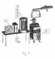
- Figure 1shows a first embodiment of the present invention, wherein a scanning device 100 and an instrument holding unit 200 are arranged in a cylindrical housing.
- an infrared camera unit 150may be mounted in the housing to check the condition or shape or quality of active or passive markers, for example, by blasting infrared radiation onto the markers and reflecting the reflected infrared radiation from the Infrared camera unit 150 is detected or detected by the infrared radiation emitted by the markers of the infrared camera unit 150.
- the instrument 700is preferably solid within the housing in the instrument holding unit 200 in the present embodiment positioned, wherein on the instrument 700, a reference system 800 is mounted and the instrument 700 has a tool tip 900 as a functional element.
- An RFID tag 950is located inside the instrument 700 and / or the reference system 800.
- the scanning device 100preferably scans the instrument optically, for example by means of a laser or tactile, wherein the housing of the scanning device 100 as in the present embodiment may be open but also closed. Also, the scanning device 100 or the laser of the scanning device 100 may rotate about the instrument, or the scanning device 100 or the housing of the scanning device 100 may be configured to rotate the instrument holding unit 200 or the instrument 700 and the shape of the instrument 700 is recorded from all sides.
- the housing of the scanning device 100in particular has a size, on the basis of which common surgical instruments can be positioned in the housing of the scanning device 100 and preferably scanned completely.
- the infrared camera unit 150which is mounted in or on the housing of the scanning device 100 in the present embodiment, can examine the quality, in particular the uniform reflection behavior of the markers, for example by irradiating the markers from different angles from the infrared camera unit 150 and determining from the reflection characteristic of the markers which state or which quality the markers have.
- a uniform reflectance behavior of the markersmay indicate a good condition, or intact condition, or high quality of the markers
- a nonuniform reflection behavior or a non-uniform reflection characteristic detected with the infrared camera unit 150may indicate a damaged condition may indicate poor quality of the markers.
- the optical shape of the reference system 800 or the markerswhich together with the determined information about the geometric shape of the reference system 800 can be combined.
- the correlation of optical and geometric shapecan be used to compensate for errors occurring during navigation, depending on the viewing angle of the reference system by the camera of the navigation system due to incorrect calculation of the spatial position by eg damaged markers.
- the acquired information about the instrument 700 and the reference system 800, which is preferably arranged on the instrument 700 during the scanning process, and the position or quality of the markerscan be transmitted by the scanning apparatus 100 to a data processing unit 400, in which the acquired scan data is entered virtual model.
- the data processing unit 400may recognize or determine functional elements or functional units of the instrument 700, for example, directly from the acquired data about the geometry of the instrument 700 and the reference system 800 or may, for example, taking into account the geometric relationships of the instrument 700, such as the characteristic arrangement of the reference system 800
- Forming markersdetermine the associated functional elements, for example, by comparing the determined geometric relationships with the stored in a database geometry ratios.
- the database in which the comparison values or comparative geometry ratios can be stored or newly determined geometric relationships can be storedcan be arranged in particular in the data processing unit 400.
- the virtual three-dimensional model of the instrument 700 calculated by the data processing unit 400 or the determined information about the geometry of the instrument 700 and the reference system 800can be displayed on a display device 300, such as a touch screen, or displayed graphically.
- various alternative shapes or geometries of the instrument 700 or the functional elements of the instrument 700may also be displayed whose shape or geometry is similar to the determined geometries or functional units of the instrument from which a user may select an instrument 700 or a functional element.
- the ascertained informationcan be wired or wirelessly by the data processing unit 400, such as via WLAN or Bluetooth, via a communication unit 500 connected to the data processing unit 400 and the Navigation system 600 may be arranged to be transmitted to the navigation system, so that based on the information about the geometry of the instrument 700, a navigation operation can be performed by the navigation system 600.
- the information obtained about the geometry of the instrument 700 and the reference system 800can be taken into account and also information about the condition or the quality of the markers can be taken into account, such as damage to the markers or changes in the geometry or damage to the Instruments can be considered in the navigation process to ensure a precise navigation process.
- the time detecting unit 880detects the time of the measurement.
- the detected timeis either transmitted directly to the RFID reader / writer, which then writes the time data in the RFID tag or the time recording unit first gives time data to the data processing unit 400, which then transmits it to the RFID reader / writer.
- the time datacan be transmitted to the navigation system 600.
- FIG. 2shows a further embodiment of the present invention, wherein the data processing unit 400 is integrated in the navigation system 600 or is arranged in the navigation system and the display device 300 is integrated into the navigation system 600 or is arranged on the navigation system 600.
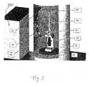
- FIG. 3shows a housing of the scanning device, in which the instrument 700 is positioned, with a scanning unit 100, an infrared camera unit 150 and an instrument holder 200, in which the instrument 700 is preferably firmly positioned.
- the instrument 700has as a functional element an instrument tip 900 whose shape can be detected, for example, by the scanning unit 100.
- a reference system 800also arranged on the instrument 700 is a reference system 800, whose shape can be detected, for example, by the scanning unit 100, wherein the reference system 800 is formed by markers whose reflection characteristic can be detected, for example, by the infrared camera unit 150.
- the RFID tag 950is in the handle of the instrument. The data stored in the RFID tag is read by the RFID reader 850.
- FIG. 4shows the display device 300 of the present invention, which graphically displays the virtual determined three-dimensional model of the instrument together with the reference system.
- a user interface unit 1000which is preferably arranged on the display device 300, for example, the markers can be selected by a user or functional elements, such as the tip 900 of the instrument, can be selected by a user.
- FIG. 5shows an inventive navigation device (navigation system) with a camera 10 for detecting a marker device 20 with marker spheres 20, 24, 26.
- the marker device 20is preferably designed as a reference star.
- the reference star 20is attached to an instrument 30 for treating a body structure 40, e.g. Attached to a human's bones.
- the reference star 20 together with the instrument 30 (e.g., knife)forms a medical treatment device.
- the marker spherescan be passive or active and are detected by a camera, which is an example of a detection device.
- the detection signals from the camera 10are transmitted to a data processing device 50.
- the instrument 30is an RFID tag that can be read by an RFID reader 850.
- the reader 850is coupled to the data processing unit 50 to communicate the read data to the data processing device 50.
- the read datapreferably includes data about the geometric characteristics of the instrument 30 and / or the reference star 20.
- the RFID tag 950may be connected to the instrument 30 or to the reference star 20, e.g. glued to it or be in its interior.
- the read-out dataare preferably the geometric properties of the instrument 30 and / or the reference star 20. Further, time data are included, which represent the time of measurement of the geometric properties. In accordance with an additional embodiment, data is further included which is the type of instrument and / or the reference star describe. All of these data are preferably read by the reading device 850 and transmitted to the data processing device 50.
- the data processing device 50calculates a set point in time, to which a validity of the data for the geometric properties is given. This target time can also be called the expiration date.
- the aforementioned target timeis stored alternatively or additionally to the time of the measurement in the RFID transponder of the medical treatment device. That the data processing device, which is used in the measurement of the geometric properties of the medical treatment device, calculates from the measured time, when measuring the geometric data by means of the measuring device, the aforementioned target time, which then in the RFID transponder of the medical treatment device by means of the RFID Writing instrument is written.
- this setpoint timewhich can also be referred to as the expiration time
- this setpoint timecan be read out by the reading device 850, which is shown in FIG.
- a target timeis preferably compared with the current time. If the target time is before the current time, a target time-out operation is preferably performed.
- a warning signalis displayed in the display device 60.
- the display device 60may be used to represent the position of the instrument 30. Alternatively or additionally, the representation of the instrument 30 on the display device 60 can be prevented, for example, by turning off the display device 60 by controlling the data processing device 50.
- a warning tone signalcan be issued.
- an identification codecan also be read from the RFID transponder 59, which specifies the medical treatment device. If the data processing unit 50 calculates the setpoint time, the calculation of this setpoint time can be carried out as a function of the identified instrument. For this purpose, the data processing device 50 accesses, for example, a database which defines different validity periods from the time of measurement of the geometric properties for different types of instruments. This makes sense, since different medical treatment devices have different mechanical stability and are subjected to a different typical load in medical practice. Thus, the data processing device 50 preferably accesses, for example, a table in dependence on the identification code, in which it is determined which type of instrument matches the identification code of the instrument.
- the desired period dimension of the geometric propertiesis then read from a table.
- the aforementioned target timeis then calculated.
- a codecan also be read from the RFID transponder, which characterizes the type of the instrument, so that within the data processing device 50, it is not necessary to use a table that has a connection between the identification code and the type of instrument.
- the above-described characteristics of the data processing device 50can also be realized in the data processing device 400, which is used in the measurement of the geometric properties of the medical treatment device.
- a target timecan already be determined during the measurement of the properties of the medical treatment device and this can be written into the RFID transponder of the medical treatment device by means of the RFID writing instrument alternatively or additionally to the time of measurement by the measuring device according to the invention ,
- the type the medical device treatment deviceare written in the RFID transponder.
Landscapes
- Health & Medical Sciences (AREA)
- Surgery (AREA)
- Life Sciences & Earth Sciences (AREA)
- Engineering & Computer Science (AREA)
- Molecular Biology (AREA)
- Animal Behavior & Ethology (AREA)
- Veterinary Medicine (AREA)
- Biomedical Technology (AREA)
- Heart & Thoracic Surgery (AREA)
- Medical Informatics (AREA)
- Nuclear Medicine, Radiotherapy & Molecular Imaging (AREA)
- Public Health (AREA)
- General Health & Medical Sciences (AREA)
- Pathology (AREA)
- Oral & Maxillofacial Surgery (AREA)
- Robotics (AREA)
- Physics & Mathematics (AREA)
- Electromagnetism (AREA)
- Length Measuring Devices By Optical Means (AREA)
- Length Measuring Devices With Unspecified Measuring Means (AREA)
Abstract
Description
Translated fromGermanDie vorliegende Erfindung betrifft Vorrichtungen und Verfahren zum Messen geometrischer Eigenschaften medizintechnischer Behandlungsvorrichtung, insbesondere zur automatischen Verifikation, Kalibrierung und Vermessung von Instrumenten für den Einsatz in computer-assistierter Chirurgie. Dabei können insbesondere mit Hilfe von optischen Scanverfahren die Geometrie des Instruments und eines durch mindestens zwei Marker gebildetes Referenzsystems, welches permanent oder abnehmbar am Instrument befestigt sein kann, als dreidimensionales Modell ermittelt und anschließend vom Navigationssystem weiterverwendet werden. Sowohl ein Instrument ohne Referenzsystem als auch ein Instrument mit Referenzsystem sowie ein Referenzsystem (z.B. Markereinrichtung) für ein Instrument (z.B. ein mit einem Instrument verbindbares Referenzsystem) stellen Beispiele für eine medizintechnische Behandlungsvorrichtung dar.The present invention relates to apparatus and methods for measuring geometric characteristics of medical treatment apparatus, in particular for automatic verification, calibration and measurement of instruments for use in computer-assisted surgery. In particular, with the aid of optical scanning methods, the geometry of the instrument and a reference system formed by at least two markers, which can be permanently or detachably attached to the instrument, can be determined as a three-dimensional model and subsequently used by the navigation system. Both a non-reference instrument and an instrument with reference system and a reference system (e.g., marker means) for an instrument (e.g., an instrument-connectable reference system) are examples of a medical treatment device.
Die Genauigkeit und damit Schnelligkeit des beispielhaften Scanprozesses wird maßgeblich über die bereits für dieses Instrument vorhandenen und zugänglichen Informationen gesteuert, wobei mindestens eine Verifikation, durchaus aber eine Kalibrierung und sogar eine vollständige Vermessung der Instrumenteneigenschaften durchgeführt werden kann oder sogar muss.The accuracy and therefore speed of the exemplary scanning process is significantly controlled by the already existing and accessible for this instrument information, with at least one verification, but quite a calibration and even a complete measurement of the instrument properties can be performed or even must.
Bei computergestützten Operationen werden dem Operateur die Position und Orientierung von chirurgischen Instrumenten in Beziehung zu den anatomischen Strukturen des Patienten mit Hilfe eines Navigationssystems auf dessen Anzeigevorrichtung dargestellt. Notwendigerweise müssen für eine genaue Darstellung neben den anatomischen Strukturen auch die verwendeten Instrumente durch geeignete Referenzsysteme (z. B. Markereinrichtungen) verfolgbar sein, was üblicherweise durch aktive oder passive Markerstrukturen erreicht wird, die dem Navigationssystem ihre Position im Operationsfeld durch Emmision oder Reflexion von Infrarotstrahlung offenbaren.In computer-assisted operations, the operator is presented with the position and orientation of surgical instruments in relation to the patient's anatomical structures by means of a navigation system on his display device. Necessarily need for an accurate In addition to the anatomical structures, the instruments used can also be tracked by suitable reference systems (eg marker devices), which is usually achieved by active or passive marker structures that reveal the navigation system its position in the surgical field by emission or reflection of infrared radiation.
Die anatomischen Strukturen werden zu Beginn durch Verwendung von navigierbaren Zeigegeräten in einem Registrierungsprozess mit den an ihnen befestigten Referenzsystemen in Beziehung gesetzt und sind dadurch im späteren Operationsprozess für das Navigationssystem räumlich verfolgbar.The anatomical structures are initially related by using navigable pointing devices in a registration process with the reference systems attached to them and are thereby spatially traceable in the later operation process for the navigation system.
Gleiches ist für die Instrumente und ihre Referenzsysteme (z. B. Markereinrichtungen) erforderlich, wobei hier die instrumententypischen Funktionselemente von besonderer Bedeutung sind. Dabei handelt es sich zum Beispiel um Werkzeugflächen (Schneiden, Spitzen etc.), die für die Bearbeitung von beispielsweise knöchernen Strukturen benutzt werden, wobei der Chirurg ein Navigationssystem einsetzt, um trotz möglicherweise eingeschränkter Sichtbarkeit genaue Informationen über deren Position und Orientierung zu erhalten. Die Darstellung der räumlichen Lage des Instruments und seiner Funktionselemente auf der Anzeigevorrichtung beruht auf einer Korrelation von hinterlegten Geometriedaten des Instruments und der räumlichen Daten, die vom Navigationssystem über das am Instrument angebrachte Referenzsystem ermittelbar sind. Sobald die hinterlegten Geometriedaten, die hauptsächlich die Funktionselemente in Bezug auf das Referenzsystem beschreiben, von der tatsächlichen Geometrie des Instruments abweichen (z.B. nach Beschädigung des Instruments), führt dies unweigerlich auch zu einer falschen Darstellung der Beziehung zwischen realem Instrument und zu behandelnder anatomischer Struktur, wenn weiterhin die in der Datenbank hinterlegten Informationen über die initiale Gestalt des Instruments verwendet werden.The same is necessary for the instruments and their reference systems (eg marker devices), whereby the instrument-typical functional elements are of particular importance here. These are, for example, tool surfaces (cutting edges, points, etc.) that are used for processing, for example, bony structures, whereby the surgeon uses a navigation system in order to obtain precise information about their position and orientation despite possibly limited visibility. The representation of the spatial position of the instrument and its functional elements on the display device is based on a correlation of stored geometric data of the instrument and the spatial data that can be determined by the navigation system via the reference system attached to the instrument. As soon as the stored geometry data, which mainly describe the functional elements with respect to the reference system, deviate from the actual geometry of the instrument (eg after damage to the instrument), this inevitably leads to a false representation of the relationship between the real instrument and the anatomical structure to be treated, if, furthermore, the information stored in the database about the initial shape of the instrument is used.
Gegenwärtig wird die Relation zwischen Funktionselement des Instruments und seinem Referenzsystem einmalig anhand von Fertigungsunterlagen festgelegt, wobei deren Einhaltung durch Vermessung nach dem Fertigungsprozess sichergestellt wird. Die Relation wird im Navigationssystem hinterlegt und für nachfolgende Operationen ausgelesen und verwendet. Diese sogenannten prä-kalibrierten Instrumente (z.B. Bohrführungen) werden mitunter prä-operativ mit navigierbaren Hilfsmitteln verifiziert, um die Maßhaltigkeit zu bestätigen. Bei unzureichender Maßhaltigkeit wird dies dem Benutzer angezeigt, welcher auf den Einsatz des Instruments verzichten sollte, wenn eine nachfolgend beschriebene Kalibrierung nicht möglich ist. Eine Anpassung der Modelldaten an das real existierende, eventuell abweichende Instrument, ist bei der Verifikation nicht möglich. Die erreichbare Genauigkeit der Verifikation hängt zwangsläufig von der Genauigkeit des Navigationssystems ab, da wiederum die jeweiligen Referenzsysteme zueinander in Relation gesetzt werden. Sichtbarkeitsprobleme und mitunter schlechte Handhabbarkeit beim gleichzeitigen Positionieren von Instrument und Hilfsmittel bewirken dabei tendenziell eine Verlängerung der Operationszeit.At present, the relation between the functional element of the instrument and its reference system is determined once based on manufacturing documents, wherein compliance is ensured by measuring after the manufacturing process. The relation is stored in the navigation system and read out and used for subsequent operations. These so-called pre-calibrated instruments (eg drill guides) are sometimes pre-operatively verified with navigable tools to confirm the dimensional accuracy. In the case of insufficient dimensional stability, this is indicated to the user who should refrain from using the instrument if a calibration as described below is not possible. An adaptation of the model data to the actually existing, possibly deviating instrument is not possible during the verification. The achievable accuracy of the verification inevitably depends on the accuracy of the navigation system, since in turn the respective reference systems are related to each other. Visibility problems and sometimes poor handling when simultaneously positioning the instrument and the aid tend to prolong the duration of the operation.
Bei einem weiteren Verfahren wird vor dem Gebrauch des Instruments ein Kalibrierungsvorgang des Instruments durchgeführt. Dabei werden die für die Navigation erforderlichen aber noch offenen Werte funktionsrelevanter Parameter des Instruments (Länge, Durchmesser, ...) oder offene Werte für die Zuordung von Referenzsystem zu Funktionselement (z.B. Pfanneneinschläger mit variablen Pfannen) oder die Abweichungen des realen Instruments vom in der Datenbank hinterlegten Modell mittels eines navigierbaren Kalibrierungswerkzeugs bestimmt, vorrübergehend oder permanent im Navigationssystem gespeichert und bei Bedarf ausgelesen. Auch hier wirken sich die vorstehend beschriebenen Sichtbarkeits- und Handhabbarkeitsprobleme negativ auf die Operationszeit aus. Die Kalibrierung funktioniert gut für Instrumente mit einfachen Geometrien der Funktionselemente aber wiederum nur in den Grenzen der vom Navigationssystem erreichbaren Genauigkeit.Another method involves calibrating the instrument prior to use of the instrument. The values required for the navigation but still open function - relevant parameters of the instrument (length, diameter, ...) or open values for the assignment of reference system to functional element (eg Pfannenschläger with variable pans) or the deviations of the real instrument from in the Database stored model determined by a navigable calibration tool, temporarily or permanently stored in the navigation system and read out as needed. Again, the visibility and manageability issues described above adversely affect the operation time. The calibration works well for instruments with simple geometries of the functional elements but again only within the limits of the accuracy achievable by the navigation system.
Die vollständige Vermessung insbesondere funktionsrelevanter Strukturen eines schwer zu kalibrierenden oder zu verifizierenden Instruments stellt ein drittes Verfahren dar, das gegenwärtig jedoch nicht zum Einsatz kommt, da weder die geeigneten Hilfsmittel zur Verfügung stehen, noch die erforderlichen Prozeduren in einem vertretbaren zeitlichen Rahmen vom OP-Personal durchgeführt werden könnten.The complete survey of particular functionally relevant structures of a tool that is difficult to calibrate or verify is a third method that is currently not used because neither the appropriate tools are available nor the required procedures could be carried out by OR staff within a reasonable time frame.
Gegenwärtig werden mittels einer Detektionseinrichtung (z. B. Kamera oder Ultraschalldetektor) Markereinrichtungen detektiert, die Beispiele für ein Referenzsystem darstellen. Derartige Detektionssysteme werden auch als Navigationssysteme bezeichnet, wie sie bei der IGS (image guided segery) verwendet werden. Bei den Markereinrichtungen handelt es sich typischerweise um drei Marker, die in fester und vorbestimmter relativer Lage zueinander angeordnet sind und insbesondere mechanisch verbunden sind. Die Marker können passive oder aktive Marker sein, wobei die passiven Marker Signale (z.B. Wellen und/oder Strahlung) reflektieren, die in ihre Richtung ausgesendet werden und die aktiven Marker selbst Ursprung der Signale (z.B. Strahlung und/oder Wellen) sind. Die von den (aktiven oder passiven) Markern ausgehenden Signale, bei denen es sich um Wellensignale oder Strahlungssignale handeln kann, werden von einer Detektionsvorrichtung (z. B. Kamera detektiert). Um eine Position der Markereinrichtung relativ zu der Detektionseinrichtung festzulegen, wird dabei vorzugsweise die Markereinrichtung bewegt, um der Detektionseinrichtung verschiedene Ansichten der Markereinrichtung zu bieten. Auf dieser Grundlage kann dann in bekannter Weise die relative Lage der Markereinrichtung relativ zu der Detektionseinrichtung, insbesondere in einem im Raum ruhenden Bezugssystem bestimmt werden. In diesem Zusammenhang wird auf die
Die durchgeführte Kalibrierung kann im Laufe der Zeit ihre Gültigkeit verlieren, insbesondere können die geometrischen Eigenschaften der medizintechnischen Behandlungsvorrichtung sich im Laufe der Zeit ändern. Dies kann durch Abnutzungserscheinungen oder wiederholte oder einmalige mechanische Belastung verursacht sein.The calibration performed may lose its validity over time, in particular the geometric characteristics of the medical device may change over time. This can be caused by signs of wear or repeated or single mechanical stress.
Aufgabe der Erfindung ist es das Risiko der Benutzung einer medizintechnischen Behandlungsvorrichtung zu reduzieren, für das Daten über geometrischen Eigenschaften vorliegen, die nicht mehr gültig sind.The object of the invention is to reduce the risk of using a medical treatment device for which there are data on geometric properties that are no longer valid.
Vorstehende Aufgabe wird durch die Gegenstände der unabhängigen Ansprüche gelöst. Vorteilhafte Ausführungsformen gehen aus den Unteransprüchen hervor.The above object is solved by the subject matters of the independent claims. Advantageous embodiments will become apparent from the dependent claims.
Vorteilhaft wird ein Verfahren und Vorrichtungen zur Verifikation, Kalibrierung und Vermessung von Instrumenten für die computer-assistierte Chirurgie bereitgestellt, welche eine Erhöhung der Prozesssicherheit und mitunter eine Zeiteinsparung beim Einsatz von navigierten Instrumenten für chirurgische Prozeduren ermöglichen. Dabei soll die Anwendbarkeit nicht auf symmetrische oder anderweitig geometrisch einfache navigierbare Instrumente beschränkt sein, sondern es sollen auch Instrumente mit komplexen Geometrien für den Einsatz in computer-assistierter Chirurgie vorbereitet werden.Advantageously, there is provided a method and apparatus for verifying, calibrating, and surveying instruments for computer-assisted surgery that provides for increased process reliability and sometimes time savings in the use of navigated surgical procedure instruments. The applicability should not be restricted to symmetrical or otherwise geometrically simple navigable instruments, but instruments with complex geometries should also be prepared for use in computer-assisted surgery.
Die vorliegende Erfindung betrifft allgemein Messvorrichtungen und Verfahren zum Messen geometrischer Eigenschaften einer medizintechnischen Behandlungsvorrichtung, insbesondere eines Instruments oder eines Instruments mit Referenzsystem oder eines Referenzsystems für ein Instrument. Eine Verifikation, Kalibrierung und/oder _Vermessung der Medizintechnischen Behandlungsvorrichtung stellen ein Bespiel für ein Messen der geometrischen Eigenschaften der medizintechnischen Behandlungsvorrichtung dar. Eine geometrische Eigenschaft einer medizintechnischen Behandlungsvorrichtung ist beispielsweise die relative Lage zwischen mindestens einem ersten Teil der medizintechnischen Behandlungsvorrichtung und mindestens einem zweiten Teil der medizintechnischen Behandlungsvorrichtung, wobei sich der zweite Teil vom ersten Teil unterscheidet. Beispielsweise kann der erste Teil ein Funktionselement des Instruments, z. B. eine Instrumentenspitze sein. Der zweite Teil kann ein Griff des Instruments sein oder eine am Instrument angebrachte Markereinrichtung. Auch kann der erste Teil eine erste Markerkugel einer Markereinrichtung und der zweite Teil eine zweite Markerkugel der Markereinrichtung sein.The present invention relates generally to measuring devices and methods for measuring geometric properties of a medical treatment device, in particular an instrument or instrument with reference system or a reference system for an instrument. A verification, calibration and / or _Vermessung the medical treatment device represent an example of measuring the geometric characteristics of the medical treatment device. A geometric property of a medical treatment device, for example, the relative position between at least a first part of the medical device and at least a second part of the treatment medical treatment device, wherein the second part is different from the first part. For example, the first part may be a functional element of the instrument, e.g. B. be an instrument tip. The second part may be a handle of the instrument or a marker device attached to the instrument. Also the first part may be a first marker sphere of a marker device and the second part may be a second marker sphere of the marker device.
Die Lage der oben genannten Teile wird bevorzugt durch die Position der Teile in einem vorbestimmen Bezugssystem bestimmt. Vorzugsweise wird als Bezugssystem ein Bezugssystem verwendet, in dem eine Detektionseinrichtung (z.B. Kamera) oder die Messvorrichtung (z.B. Scaneinheit) ruht. Die Positionen können zum Beispiel mit kartesischem Koordinaten oder Kugelkoordinaten beschrieben werden. Die relative Lage von einem Teil (z. B. erster Teil) zu einem anderen Teil (z. B. zweiter Teil) kann insbesondere durch Raumwinkel und/oder Abstände und/oder Koordinaten (in einem Bezugssystem) und/oder Vektoren beschrieben werden und wird vorzugsweise aus dem die Lage beschreibenden Positionen z. B. mittels eines Programms errechnet, das auf einem Computer läuft.The location of the above-mentioned parts is preferably determined by the position of the parts in a predetermined reference frame. Preferably, a reference system in which a detection device (e.g., camera) or the measurement device (e.g., scanning unit) rests is used as the reference system. The positions can be described, for example, with Cartesian coordinates or spherical coordinates. The relative position of one part (eg first part) to another part (eg second part) can be described in particular by solid angles and / or distances and / or coordinates (in a frame of reference) and / or vectors and is preferably from the position describing the position z. B. calculated by means of a program that runs on a computer.
Der hierin verwendete Begriff "relative Lage" oder der Ausdruck "Lage eines Teils A relativ zu einem Teil B" umfasst also den Begriff der relativen Positionen zwischen den zwei Teilen.The term "relative position" as used herein or the term "position of a part A relative to a part B" thus includes the notion of the relative positions between the two parts.
Erfindungsgemäß soll die Zeit der Messung der geometrischen Eigenschaft erfasst werden und mittels eines RFID-Schreibgeräts in einen RFID-Transponder geschrieben werden, der sich z.B. in der medizintechnischen Behandlungsvorrichtung befindet. Dadurch kann, beim Lesen des RFID-Transponders bestimmt werden, wie lange die Messung zurück liegt und wie zuverlässig somit die Messdaten sind. Je länger der Messvorgang zurückliegt, desto wahrscheinlicher ist es, dass die gemessenen geometrischen Eigenschaften nicht mehr gültig sind. Desto dringender ist also eine neue Messung gefordert. Ein Beispiel für einen RFID-Transponder ist ein RFID-Etikett, ein RFID-Chip oder ein RFID-Tag. Die Abkürzung "RFID" steht für Radio Frequency Identification.According to the invention, the time of the measurement of the geometric property is to be detected and written by means of an RFID writing instrument in an RFID transponder, which can be e.g. located in the medical treatment device. As a result, when reading the RFID transponder, it can be determined how long the measurement has gone and how reliable the measured data is. The longer the measuring process, the more likely it is that the measured geometric properties are no longer valid. The more urgent is therefore a new measurement required. An example of an RFID transponder is an RFID tag, an RFID chip or an RFID tag. The abbreviation "RFID" stands for Radio Frequency Identification.
Die Zeiterfassungseinheit ist beispielsweise eine Uhr (insbesondere Funkuhr), die vorzugsweise mit der Messeinheit gekoppelt ist, insbesondere Signale von der Messeinheit empfängt. Die Zeiterfassungseinheit empfängt beispielsweise ein Signal, wenn die Messeinheit die Messung beginnt und/oder wenn die Messeinheit mit der Messung der geometrischen Eigenschaft oder der geometrischen Eigenschaften der medizinischen Behandlungsvorrichtung in Gang ist oder zu Ende ist. Die Zeiterfassungseinheit stellt dann die Zeit fest, wann dieses Signal empfangen wurde. Die Zeiterfassung kann von unterschiedlicher Genauigkeit sein. Beispielsweise kann die Tageszeit auf die Stunde genau, die Minute genau oder die Sekunde genau bestimmt werden. Beispielsweise kann auch nur das Datum, also Tag, Monat und Jahr oder auch nur die Woche und das Jahr oder der Monat und das Jahr bestimmt werden. Eine ungenaue Zeiterfassung ist insbesondere dann tolerierbar, wenn für die medizintechnische Behandlungsvorrichtung üblicherweise eine geometrische Eigenschaft erwartet wird, die über lange Zeit, beispielsweise Jahre typischerweise stabil ist.The time recording unit is, for example, a clock (in particular a radio clock), which is preferably coupled to the measuring unit, in particular receives signals from the measuring unit. For example, the time detection unit receives a signal when the measurement unit starts the measurement and / or when the measurement unit starts measuring the geometric property or geometrical properties of the measurement unit medical treatment device is in progress or over. The time acquisition unit then determines the time when this signal was received. The time tracking can be of different accuracy. For example, the time of day can be accurately determined to the hour, the minute or the exact second. For example, only the date, ie day, month and year or just the week and the year or the month and the year can be determined. Inaccurate time recording is tolerable, in particular, when a geometric property that is typically stable for a long time, for example years, is usually expected for the medical treatment apparatus.
Die vorliegende Erfindung ist insbesondere auch auf ein System aus der Messvorrichtung in Verbindung mit einer medizintechnischen Behandlungsvorrichtung gerichtet. Bei dem in der medizintechnischen Behandlungsvorrichtung verwendeten RFID-Transponder kann es sich insbesondere um einen handeln, der einen mehrfachbeschreibbaren Speicher umfasst. Auf diese Art und Weise ist es möglich, bei einer erneuten Vermessung der medizintechnischen Behandlungsvorrichtung die aktuelle Zeit der Messung in den RFID-Transponder einzuschreiben.The present invention is particularly directed to a system of the measuring device in connection with a medical treatment device. The RFID transponder used in the medical treatment device can in particular be one that comprises a rewritable memory. In this way, it is possible to write the current time of the measurement in the RFID transponder in a renewed measurement of the medical treatment device.
Vorzugsweise ist die erfindungsgemäße Messvorrichtung so ausgebildet, dass das RFID-Schreibgerät Messdaten von der Messeinheit erhält. Beispielsweise ist das RFID-Schreibgerät signaltechnisch mit der Messeinheit verbunden oder mit einer Datenverarbeitungseinrichtung, die die gemessenen Daten verarbeitet. Vorzugsweise ist das RFID-Schreibgerät ausgebildet, zusätzlich zu der erfassten Zeit auch Messdaten der Messeinheit in den RFID-Transponder der medizintechnischen Behandlungsvorrichtung zu schreiben.Preferably, the measuring device according to the invention is designed so that the RFID writing instrument receives measurement data from the measuring unit. For example, the RFID writing device is connected by signal technology to the measuring unit or with a data processing device that processes the measured data. Preferably, the RFID writing instrument is designed to write measurement data of the measuring unit in the RFID transponder of the medical treatment device in addition to the detected time.
Erfindungsgemäß misst die Messeinheit zumindest die relative Lage zwischen einem ersten Teil der medizintechnischen Behandlungsvorrichtung und einem zweiten Teil der medizintechnischen Behandlungsvorrichtung. Dies bedeutet, dass auch eine umfassendere Messung, wie beispielsweise eine Kalibrierung, bei der die relative Lage vieler Teile der medizintechnischen Behandlungsvorrichtung zueinander bestimmt wird, umfasst ist. Die erfindungsgemäße Messeinheit kann als so genannter Pointer ausgebildet sein, d.h. ein Zeigegerät mit mindestens zwei Markerkugeln, das von einem Kamerasystem, insbesondere Navigationssystem während des Abtastvorgangs beobachtet wird. Beim Abtastvorgang werden Teile der medizintechnischen Behandlungsvorrichtung mittels des Pointers abgegriffen. Aus den Beobachtungssignalen wird die relative Lage zwischen den Teilen bestimmt.According to the invention, the measuring unit measures at least the relative position between a first part of the medical treatment device and a second part of the medical treatment device. This means that a more comprehensive measurement, such as a calibration, in which the relative position of many parts of the medical treatment device to each other is determined, is also included. The measuring unit according to the invention can be used as such be formed pointer, ie a pointing device with at least two marker spheres, which is observed by a camera system, in particular navigation system during the scanning process. During the scanning process, parts of the medical treatment device are tapped by means of the pointer. From the observation signals, the relative position between the parts is determined.
Insbesondere ist die erfindungsgemäße Messeinheit als Scanneinheit ausgebildet, die die Geometrie eines Instruments einschließlich eines daran angebrachten Referenzsystems erfasst. Vorzugsweise umfasst die erfindungsgemäße Vorrichtung weiter eine Datenverarbeitungseinheit, die beispielsweise ausgebildet ist mittels der erfassten Geometrie des Instruments und des Referenzsystems ein dreidimensionales Modell des Instruments berechnet. Andere beispielhafte Funktionen der Datenverarbeitungseinheit sind unten beschrieben.In particular, the measuring unit according to the invention is designed as a scanning unit which detects the geometry of an instrument including a reference system mounted thereon. Preferably, the device according to the invention further comprises a data processing unit which, for example, is designed to calculate a three-dimensional model of the instrument by means of the detected geometry of the instrument and of the reference system. Other exemplary functions of the data processing unit are described below.
Gemäß einer bevorzugten Ausführungsform kann die Messvorrichtung eine Datenverarbeitungseinrichtung umfassen, die aus der erfassten Zeit, also der Zeit der Messung eine Soll-Zeit berechnet. Die Soll-Zeit kann als eine Verfallszeit der medizintechnischen Behandlungsvorrichtung aufgefasst werden. Nach dem Ablauf eines Zeitraums nach Messung der geometrischen Eigenschaften kann es sein, dass die geometrischen Eigenschaften nicht mehr gültig sind, insbesondere das Risiko erhöht ist, dass die geometrischen Eigenschaften nicht mehr gültig sind. Addiert man diesen Zeitraum zu der Zeit der Messung, so ergibt sich die vorgenannte Soll-Zeit. Die Soll-Zeit kann je nach Typ des vermessenen Instruments variieren. Vorzugweise umfasst deshalb die Datenverarbeitungseinrichtung eine Datenbank, in der in Abhängigkeit vom Instrumententyp verschiede Zeiträume (Soll-Zeiträume) abgespeichert sind, nach denen davon ausgegangen wird, dass die geometrischen Eigenschaften der medizintechnischen Behandlungsvorrichtung nicht mehr gütig sind. Die Zeit, die mittels des RFID-Schreibgeräts in den RFID-Transponder geschrieben wird, kann also die vorgenannte Messzeit und/oder die Soll-Zeit sein.According to a preferred embodiment, the measuring device may comprise a data processing device which calculates a desired time from the detected time, that is to say the time of the measurement. The target time can be understood as an expiration time of the medical treatment device. After the expiration of a period after measurement of the geometric properties, it may be that the geometric properties are no longer valid, in particular the risk is increased that the geometric properties are no longer valid. If one adds this period to the time of the measurement, then the aforementioned target time results. The target time may vary depending on the type of instrument being measured. Preferably, therefore, the data processing device comprises a database in which, depending on the type of instrument different periods (target periods) are stored, according to which it is assumed that the geometric characteristics of the medical device treatment device are no longer benevolent. The time that is written by means of the RFID writing device in the RFID transponder, so may be the aforementioned measurement time and / or the target time.
Der Typ der medizintechnischen Behandlungsvorrichtung kann beispielsweise von einem Benutzer eingegeben werden oder mittels der Messdaten basierend auf den typischen Geometriedaten der medizintechnischen Behandlungsvorrichtung oder basierend auf einem Modell bestimmt werden, dass anhand der Messdaten ermittelt wurde. Insbesondere kann es sich dabei um ein dreidimensionales Modell handeln, wie weiter unten in Zusammenhang mit der Vermessung beschreiben wird. Dadurch kann eine voll automatische Bestimmung des Typs des vermessenen Instruments durchgeführt werden. Insbesondere können hierzu verschiedene Modelle der medizintechnischen Behandlungsvorrichtungen (Instrumente und/oder Referenzsysteme) abgespeichert sein. Damit kann eine vollautomatische Bestimmung des Typs der medizintechnischen Behandlungsvorrichtung durchgeführt werden, wobei die Daten über den bestimmten Typ in Verbindung mit der bestimmten Zeit (Zeit der Messung und/oder Soll-Zeit) in den RFID-Transponder geschrieben werden. Somit kann auch der bestimmte Typ der medizintechnischen Behandlungsvorrichtung von dem RFID-Schreibgerät, das bevorzugt mit der Datenverarbeitungseinrichtung gekoppelt ist, in den RFID-Transponder geschrieben werden (z.B. zusätzlich zu den Zeit-Daten und Messdaten).The type of medical treatment device, for example, can be entered by a user or determined by means of the measurement data based on the typical geometry data of the medical treatment device or based on a model that determines based on the measurement data has been. In particular, it may be a three-dimensional model, as will be described below in connection with the survey. Thereby, a fully automatic determination of the type of the measured instrument can be performed. In particular, different models of medical treatment devices (instruments and / or reference systems) can be stored for this purpose. Thus, a fully automatic determination of the type of medical treatment device can be carried out, wherein the data on the specific type in connection with the specific time (time of measurement and / or target time) are written in the RFID transponder. Thus, the particular type of medical treatment device can also be written by the RFID writing device, which is preferably coupled to the data processing device, into the RFID transponder (eg, in addition to the time data and measurement data).
Weiter ist die Erfindung vorzugsweise auf ein Navigationssystem gerichtet, das das Navigieren einer medizintechnischen Behandlungsvorrichtung erlaubt und auch die oben genannte Datenverarbeitungseinheit umfassen kann. Das Navigationssystem umfasst dabei vorzugsweise ein RFID-Lesegerät, das die Zeit ausliest, die in dem RFID-Transponder der medizintechnischen Behandlungsvorrichtung gespeichert ist. Vorzugsweise ist das Navigationssystem so gestaltet, dass die ausgelesene Zeit mit der Soll-Zeit verglichen wird. Liegt die ausgelesene Zeit nach der Soll-Zeit so wird vorzugsweise von dem Navigationssystem eine Soll-Zeit-Überschreitungsoperation durchgeführt. Diese Soll-Zeit-Überschreitungsoperation umfasst beispielsweise das Abgeben eines Warnsignals, dass den Benutzer warnt, dass die geometrischen Eigenschaften der Behandlungsvorrichtung bereits seit längerer Zeit nicht mehr gemessen wurden, insbesondere sie nicht kalibriert wurde. Deshalb besteht ein erhöhtes Risiko, dass vom Navigationssystem verwendete Daten über die geometrischen Eigenschaften der medizintechnischen Behandlungsvorrichtung, insbesondere Kalibrierdaten nicht mehr gültig sind. Alternativ oder zusätzlich kann die Soll-Zeit- Überschreitungsoperation so gestaltet sein, dass ein Navigieren mit der medizintechnischen Behandlungsvorrichtung unterbunden wird. Dies ist insbesondere dann von Vorteil, wenn vom Hersteller der medizintechnischen Behandlungsvorrichtung eine Beibehaltung der geometrischen Eigenschaften nur für einen bestimmten Zeitraum garantiert wird. Vorzugsweise umfasst das Navigationssystem eine Datenverarbeitungseinheit, die beispielsweise die oben genannten Vergleichs- und/oder Soll-Zeit-Überschreitungsoperationen steuert und/oder durchführt.Furthermore, the invention is preferably directed to a navigation system that allows navigation of a medical treatment device and may also include the above-mentioned data processing unit. The navigation system preferably comprises an RFID reader that reads the time that is stored in the RFID transponder of the medical treatment device. Preferably, the navigation system is designed so that the read time is compared with the target time. If the read time is after the target time, a target time-out operation is preferably performed by the navigation system. This target time-out operation includes, for example, the issuing of a warning signal that warns the user that the geometric properties of the treatment device have not been measured for a long time, and in particular that it has not been calibrated. Therefore, there is an increased risk that data used by the navigation system on the geometric characteristics of the medical treatment device, in particular calibration data are no longer valid. Alternatively or additionally, the desired time-exceeding operation can be designed so that a navigation is prevented with the medical treatment device. This is particularly advantageous if the manufacturer of the medical treatment device guarantees a retention of the geometric properties only for a certain period of time. Preferably, this includes Navigation system, a data processing unit that controls and / or performs, for example, the above-mentioned comparison and / or target time-exceeding operations.
Wird eine medizintechnische Behandlungsvorrichtung mit der erfindungsgemäßen Messvorrichtung erneut vermessen, insbesondere erneut kalibriert, so wird, wie oben ausgeführt, vorzugsweise der RFID-Transponder der medizintechnischen Behandlungsvorrichtung ausgelesen. Vorzugsweise werden sowohl die erfasste Zeit als auch die früher gemessenen geometrischen Eigenschaften ausgelesen. Vorzugsweise vergleicht die Datenverarbeitungseinheit, die aus dem RFID-Transponder ausgelesenen geometrischen Daten mit den neu gemessenen Daten. Unterscheiden sich diese Daten zumindest in einem vorbestimmten Umfang, so wird vorzugsweise eine Soll-Zeit, bei der eine erneute Messung durchgeführt werden soll festgelegt, die nach einem Zeitraum liegt, der kürzer ist als der Zeitraum zwischen der letzten Messung und der aktuellen Messung. Unterscheiden sich die neu gemessenen geometrischen Eigenschaften nicht von dem im RFID-Transponder gespeicherten geometrischen Eigenschaften, so wird eine Soll-Zeit vorzugsweise gesetzt, die nach einem Zeitraum liegt, der gleich dem Zeitraum zwischen der letzten Messung und der aktuellen Messung ist oder länger ist.If a medical treatment device with the measuring device according to the invention is again measured, in particular recalibrated, then, as stated above, preferably the RFID transponder of the medical treatment device is read out. Preferably, both the detected time and the previously measured geometric properties are read out. Preferably, the data processing unit compares the geometric data read from the RFID transponder with the newly measured data. If these data differ at least to a predetermined extent, it is preferable to set a target time at which a new measurement is to be performed, which is after a period of time which is shorter than the period between the last measurement and the current measurement. If the newly measured geometric properties do not differ from the geometrical properties stored in the RFID transponder, a setpoint time is preferably set which is after a time period which is equal to or longer than the period between the last measurement and the current measurement.
Vorzugsweise werden bei einem erfindungsgemäßen Navigationssystem, die im RFID-Transponder gespeicherten Daten über die geometrischen Eigenschaften verwendet, um die medizintechnische Behandlungsvorrichtung zu navigieren, insbesondere dreidimensional darzustellen.Preferably, in a navigation system according to the invention, the data stored in the RFID transponder on the geometric properties used to navigate the medical treatment device, in particular to represent three-dimensional.
Der erfindungsgemäße RFID-Transponder kann sich im Inneren der medizintechnischen Behandlungsvorrichtung befinden oder daran angebracht sein. Beispielsweise kann im Inneren ein RFID-Chip eingebaut sein oder auf die Oberfläche der medizintechnischen Behandlungsvorrichtung kann ein RFID-Etikett aufgeklebt sein.The RFID transponder according to the invention can be located inside the medical treatment device or attached thereto. For example, an RFID chip can be incorporated in the interior, or an RFID label can be glued to the surface of the medical treatment device.
Das Referenzsystem, das insbesondere als Markereinrichtung ausgebildet ist, kann ebenfalls den RFID-Transponder alternativ oder zusätzlich zu einem RFID-Transponder des Instruments umfassen. Insbesondere kann ein RFID-Transponder der Markereinrichtung charakteristische Daten der Markereinrichtung insbesondere die relative Lage der Marker (z. B. Markerkugeln) zueinander enthalten, die charakteristisch für eine Markereinrichtung sind.The reference system, which is designed in particular as a marker device, may also comprise the RFID transponder alternatively or in addition to an RFID transponder of the instrument. In particular, an RFID transponder characteristic data of the marker device, in particular the relative position of the markers (eg marker spheres) relative to one another, which are characteristic of a marker device.
Vorteilhaft dienen die Verifikation, Kalibrierung und Vermessung mittels der Messvorrichtung dazu, dass dem Navigationssystem möglichst vor Beginn der Operation korrekte Instrumentendaten über die Geometrie von den Funktionselementen und dem Referenzsystem (z. B. Markereinrichtungen) sowie deren Relation zueinander bereitgestellt und im Speicher des Navigationssystems temporär oder permanent hinterlegt werden, wobei auch eine intra-operative Anwendung der Verifikation, Kalibrierung und Vermessung nicht ausgeschlossen werden soll, um zum Beispiel zwischenzeitlich deformierte Instrumente nach der Durchführung der beschriebenen Verfahren erneut benutzen zu können. Ein erfindungsgemäßes Navigationssystem ist vorzugsweise ausgebildet diese Daten direkt aus dem RFID-Transponder der medizintechnischen Behandlungsvorrichtung auszulesen.The verification, calibration and measurement by means of the measuring device advantageously serve to provide the navigation system with correct instrument data about the geometry of the functional elements and the reference system (eg marker devices) and their relation to each other and temporarily in the memory of the navigation system or permanently stored, whereby an intra-operative application of the verification, calibration and measurement should not be excluded, for example, to be able to re-use inter-deformed instruments after performing the described methods. An inventive navigation system is preferably designed to read this data directly from the RFID transponder of the medical treatment device.
Die Instrumentendaten können Angaben über die Lage der Funktionselemente des Instruments (z. B. Instrumentenspitze) in Bezug auf ein fest angebrachtes oder abnehmbares, aus Markern (aktive oder passive Technologie) gebildetes Referenzsystem beinhalten. Die Daten können insbesondere auch angeben, wie die Funktionselemente, wie z.B. die Spitzen des Instruments, geformt sind.Instrument data may include information about the location of the functional elements of the instrument (eg, instrument tip) relative to a fixed or detachable reference system formed of markers (active or passive technology). In particular, the data may also indicate how the functional elements, e.g. the tips of the instrument are shaped.
Bei den erfindungsgemäßen Verfahren wird vorzugsweise mittels einer vorzugsweise berührungslos arbeitenden Scanvorrichtung oder Abtastvorrichtung die Geometrie des Instruments inklusive einem befestigten oder befestigbaren, aus mindestens zwei Markern gebildeten Referenzsystems ermittelt und mit bereits hinterlegten, dem Instrument oder seiner Instrumentengruppe eindeutig zuordenbaren Werten verglichen bzw. bei Vermessung neu abgelegt. Insbesondere können das Referenzsystem oder die Marker dauerhaft an dem Instrument angeordnet sein oder können zeitweise, z.B. während des Scanvorganges, angebracht werden. Die durch das Scannen gewonnenen Oberflächendaten des Instruments werden dabei mittels einer Datenverarbeitungseinheit oder Recheneinheit in ein dreidimensionales Modell des Instruments umgewandelt, anhand dessen die instrumententypischen Kennwerte berechnet werden können. Das dreidimensionale Modell des Instruments kann dabei alle zur Navigation notwendigen Informationen über die Geometrie der Funktionselemente des Instruments und seines Referenzsystems sowie deren Beziehung zueinander beinhalten. Abschließend können die geometrischen Informationen über das Instrument dem Navigationssystem übergeben werden, um dem Operateur die Verwendung des Instruments in der computer-assistierten Chirurgie zu ermöglichen.In the method according to the invention, the geometry of the instrument, including a fixed or attachable reference system formed from at least two markers, is preferably determined by means of a preferably non-contact scanning device or scanning device and compared with previously stored values which can be unambiguously assigned to the instrument or its instrument cluster or new when measured stored. In particular, the reference system or the markers can be permanently arranged on the instrument or can be attached temporarily, eg during the scanning process. The surface data of the instrument obtained by the scanning are converted by means of a data processing unit or arithmetic unit into a three-dimensional model of the instrument, on the basis of which the instrument-typical characteristic values can be calculated. The three-dimensional model of the instrument can contain all information necessary for navigation about the geometry of the functional elements of the instrument and its reference system and their relationship to each other. Finally, the geometric information about the instrument can be passed to the navigation system to allow the surgeon to use the instrument in computer-assisted surgery.
Die erfindungsgemäßen Vorrichtungen und Verfahren werden nachfolgend beschrieben.The devices and methods of the invention will be described below.
Die Scanvorrichtung ist ein Beispiel für eine Messeinheit, die entweder im Gehäuse des Navigationssystems integriert oder in einem separaten Gehäuse untergebracht sein kann. Die Scanvorrichtung verwendet bekannte 3D-Scantechniken, wie z.B. Lichtschnittverfahren, Objektrasterverfahren, welche eine gerasterte Instrumentenoberfläche erfordern, oder Gitterprojektionsverfahren, bei welchen telezentrisches Gitter auf die Instrumentenoberfläche projiziert werden. Die in der Scanvorrichtung befindliche Scaneinheit arbeitet vorzugsweise optisch, wie mittels eines Lasers, wobei die Oberfläche des Instruments inklusive dauerhaft oder abnehmbar befestigtem Referenzsystem abgetastet wird. Dabei wird das zu scannende Instrument in einem in der Scanvorrichtung enthaltenen Instrumentenhalter befestigt, wobei während das Scanvorgangs dieser Instrumentenhalter relativ zur Scaneinheit bewegt oder gedreht werden kann, um das Instrument der Scaneinheit von allen Seiten zugänglich und somit eine vollständige Digitalisierung der Oberfläche möglich zu machen. Alternativ kann sich auch die Scaneinheit relativ zu einem fixen Instrumentenhalter bewegen oder drehen, wobei in beiden Fällen die Bewegung oder Drehbewegungen über geeignete, in der Scanvorrichtung integrierte Sensorik erfasst oder gesteuert werden kann, um die Winkelstellungen eindeutig mit den Scanergebnissen korrelieren zu können, wodurch ein realitätsgetreues 3D-Model berechenbar wird.The scanning device is an example of a measuring unit that can either be integrated in the housing of the navigation system or housed in a separate housing. The scanning device uses known 3D scanning techniques, such as light-slit methods, object rastering methods that require a rasterized instrument surface, or grid projection methods in which telecentric gratings are projected onto the instrument surface. The scanning unit located in the scanning device preferably operates optically, such as by means of a laser, whereby the surface of the instrument is scanned, including a permanently or removably mounted reference system. In this case, the instrument to be scanned is mounted in an instrument holder contained in the scanning device, wherein during the scanning of this instrument holder relative to the scanning unit can be moved or rotated to make the instrument of the scanning unit accessible from all sides and thus make a complete digitization of the surface possible. Alternatively, the scanning unit can also move or rotate relative to a fixed instrument holder, in which case the movement or rotational movements can be detected or controlled via suitable sensors integrated in the scanning device in order to be able to clearly correlate the angular positions with the scan results realistic 3D model is predictable.
Zusätzlich kann während des Scanvorgangs mittels einer Infrarot-Kameraeinheit, die separat vorhanden oder in der Scanvorrichtung enthalten sein kann, aber deren Lage in Bezug auf die Scaneinheit fest und bekannt oder ermittelbar ist, ein Emmisions- bzw. Reflexionsmodell der das Referenzsystem bildenden aktiven bzw. passiven Marker bestimmt werden. Die dadurch ermittelten Informationen über die Strahlungseigenschaften der Marker in Abhängigkeit vom Betrachtungswinkel und der sich daraus ergebenden, vom Navigationssystem erfassbaren, optischen Gestalt als räumliche Lage des Referenzsystems, können mit den Ergebnissen aus der Bestimmung seiner geometrischen Gestalt (mittels Scanprozess) korreliert werden. Damit lassen sich während des operativen Einsatzes Betrachtungsfehler des Navigationssystems, die aus sich änderndem Sichtbarkeitsverhalten der Marker in bestimmmten Lagen, z.B. durch partielle Beschädigung der Marker, resultieren können, kompensieren, was eine Erhöhung der Genauigkeit der Darstellung der Lage des Instruments in Bezug auf die zu behandelnde anatomische Struktur auf der Anzeigevorrichtung des Navigationssystems bewirkt. Mit anderen Worten können beim späteren Navigationsvorgang die auf Grund z.B. beschädigter Marker auftretenden Fehlinterpretationen der räumlichen Lage des Referenzsystems durch die Kameraeinheit des Navigationssystems kompensiert und die realitätsgetreue Lage des Instruments insbesondere des Funktionselements oder der Funktionselemente in Bezug auf die anatomische Struktur berechnet und dargestellt werden.In addition, during the scanning process an infrared camera unit, which may be present separately or contained in the scanning device, but whose position with respect to the scanning unit is fixed and known or can be determined, an emission or reflection model of the reference system forming active or passive markers are determined. The thus determined information about the radiation properties of the markers as a function of the viewing angle and the resulting, detectable by the navigation system, optical shape as spatial position of the reference system, can be correlated with the results of the determination of its geometric shape (by scanning process). This makes it possible during the operational use viewing errors of the navigation system, the changing visibility of the markers in certain locations, e.g. by partial damage to the markers, which causes an increase in the accuracy of the representation of the position of the instrument with respect to the anatomical structure to be treated on the display device of the navigation system. In other words, in the later navigation process, due to e.g. Damaged markers occurring misinterpretations of the spatial position of the reference system compensated by the camera unit of the navigation system and the realistic position of the instrument, in particular the functional element or the functional elements are calculated and displayed with respect to the anatomical structure.
Die erfindungsgemäße Messvorrichtung umfasst weiter vorzugsweise eine Recheneinheit oder Datenverarbeitungseinheit. Die von der Scaneinheit erfassten Daten über die Geometrie des navigierbaren Instruments können z.B. an die Datenverarbeitungseinheit gesendet und in dieser weiterverarbeitet werden, indem z.B. die Datenverarbeitungseinheit aus den Ergebnissen des Oberflächenscans ein dreidimensionales Modell des Instruments inklusive des Referenzsystems berechnet. Vorzugsweise kann die Datenverarbeitungseinheit die erfassten Daten oder das erstellte dreidimensionale Modell so auswerten, dass die Geometrie der Funktionselemente des Instruments (z.B. Spitzen) und deren Lage zum Referenzsystem des Instruments ermittelt werden können.The measuring device according to the invention further preferably comprises a computing unit or data processing unit. The data acquired by the scanning unit on the geometry of the navigable instrument can be sent to the data processing unit, for example, and further processed in it by, for example, calculating the data processing unit from the results of the surface scan a three-dimensional model of the instrument including the reference system. Preferably, the data processing unit can evaluate the acquired data or the created three-dimensional model so that the geometry of the Functional elements of the instrument (eg tips) and their position can be determined to the reference system of the instrument.
Weiter kann die erfindungsgemäße Vorrichtung eine Datenbank umfassen, welche mit der Datenverarbeitungseinheit verbunden sein kann, so dass z.B. in die Datenverarbeitungseinheit eingegebene Daten oder an die Datenverarbeitungseinheit gesendete Daten in der Datenbank gespeichert werden können. So können beispielsweise Informationen über die Geometrie der Funktionseinheiten und des Referenzsystems des Instruments sowie deren Lage zueinander für verschiedene Instrumente aus der Datenverarbeitungseinheit in die Datenbank eingespeichert werden, genauso wie Informationen über die Qualität der Marker oder die Eigenschaften des Emmisions- bzw. Reflexionsmodels des instrumentenspezifischen Referenzsystems. Auch können geometrische Eigenschaften verschiedener Typen von Instrumenten und/oder Referenzsystemen gespeichert werden, so dass aus den gemessenen geometrischen Eigenschaften der Typ bestimmt werden kann.Furthermore, the device according to the invention may comprise a database, which may be connected to the data processing unit, so that e.g. data entered into the data processing unit or data sent to the data processing unit can be stored in the database. Thus, for example, information about the geometry of the functional units and the reference system of the instrument and their position to each other for different instruments from the data processing unit can be stored in the database, as well as information about the quality of the markers or the characteristics of the emission or reflection model of the instrument-specific reference system , Also, geometric properties of various types of instruments and / or reference systems can be stored so that the type can be determined from the measured geometric properties.
Auch kann eine Anzeigevorrichtung, insbesondere ein Bildschirm, der mit der Datenverarbeitungseinheit und der Benutzerschnittstelleneinheit drahtgebunden oder drahtlos (z.B. WLAN oder Bluetooth) kommuniziert, in der erfindungsgemäßen Messvorrichtung vorhanden sein. Die Darstellung der ermittelten Informationen über die Geometrie der Funktionselemente des Instruments und seines Referenzsystems sowie deren Lage zueinander kann in Form von Werten oder grafisch erfolgen. Vorzugsweise wird auf der Anzeigevorrichtung das aus der Datenbank ausgelesene oder durch Verarbeitung der Scannergebnisse ermittelte dreidimensionale Modell des Instruments angezeigt, wobei das Modells zumindest nahezu exakt auf der Anzeigevorrichtung dargestellt wird. Die realitätsnahe Darstellung des dreidimensionalen Modells auf der Anzeigevorrichtung gestattet es dem Benutzer unter Nutzung einer Benutzerschnittstelleneinheit, die vorzugsweise auf der Anzeigevorrichtung angeordnet ist, wie z.B. bei einem Touchscreen, notwendige Befehle für die korrekte Ausführung des erfindungsgemäßen Verfahrens an die Datenverarbeitungseinheit zu übertragen. Diese Befehle können die Auswahl des richtigen Modells aus einer Mehrzahl an ähnlichen Modellvarianten steuern, falls das Instrument nach dem Einbringen in die Scanvorrichtung nicht korrekt oder gar nicht erkannt wird. Weiterhin kann die, nach einem Grobscan mögliche grafische Darstellung von der Scanvorrichtung bis dahin unbekannten Instrumenten dafür genutzt werden, die für das erfolgreiche Durchführen der Instrumentenaufbereitung durch Vermessung erforderlichen Bereiche des Instruments, im besonderen die Funktionselemente und das Referenzsystem, interaktiv zu selektieren. Ebenso lassen sich für neue Instrumente Bezeichnungen eingeben, die das spätere Auffinden in der Datenbank erleichtern.Also, a display device, in particular a screen, which communicates with the data processing unit and the user interface unit via a wired or wireless (eg WLAN or Bluetooth) may be present in the measuring device according to the invention. The representation of the determined information about the geometry of the functional elements of the instrument and its reference system as well as their position relative to one another can take place in the form of values or graphically. The three-dimensional model of the instrument, which is read from the database or determined by processing the scanner results, is preferably displayed on the display device, the model being displayed at least almost exactly on the display device. The realistic representation of the three-dimensional model on the display device allows the user to use a user interface unit, which is preferably arranged on the display device, such as a touch screen, necessary To transmit commands for the correct execution of the method according to the invention to the data processing unit. These commands can control the selection of the correct model from a plurality of similar model variants, if the instrument is not recognized correctly or not at all after insertion into the scanning device. Furthermore, the graphic representation, which is possible after a coarse scan, of the scanning device of previously unknown instruments can be used to interactively select the areas of the instrument required for the successful performance of the instrument preparation by measurement, in particular the functional elements and the reference system. Likewise, names can be entered for new instruments, which facilitate later retrieval in the database.
Auch kann das Navigationssystem drahtlos oder drahtgebunden mit der Messvorrichtung oder der Datenverarbeitungseinheit verbunden sein, so dass die nach den erfindungsgemäßen Verfahren ermittelten Informationen über die Geometrie der Funktionselemente und des Referenzsystems des Instruments sowie deren Lage zueinander, und auch die Qualität der aktiven bzw. passiven Marker und deren daraus resultierendes Emmisions- bzw. Reflexionsmodell an das Navigationssystem, insbesondere an dessen Datenbank übertragen werden können. Mittels der Informationen kann das Navigationssystem den Operateur durch Bereitstellung der zuvor oder gerade ermittelten oder aktuellsten instrumentenspezifischen Daten bei der Durchführung der computer-assistierten Chirurgie unterstützen. Wie oben ausgeführt, erfasst das erfindungsgemäße Navigationssystem bevorzugt die Daten oder einen Teil der Daten von dem RFID-Transponder der medizintechnischen Behandlungsvorrichtung, so dass eine datentechnische Verbindung zwischen Navigationssystem und Messvorrichtung nicht oder nicht immer notwendig ist.The navigation system can also be wirelessly or wired to the measuring device or the data processing unit, so that the information determined by the inventive method on the geometry of the functional elements and the reference system of the instrument and their position to each other, and also the quality of the active or passive marker and the resulting Emmisions- or reflection model can be transmitted to the navigation system, in particular to its database. By means of the information, the navigation system can assist the surgeon in providing computer-assisted surgery by providing previously or recently determined or most recent instrument-specific data. As stated above, the navigation system according to the invention preferably captures the data or part of the data from the RFID transponder of the medical treatment device, so that a data-technical connection between the navigation system and the measuring device is not or always necessary.
Das erfindungsgemäße Verfahren von navigierbaren chirurgischen Instrumenten und die zugeordnete Zeiterfassung mit seinen unterschiedlichen Anforderungen und Bearbeitungsabläufen wird nachfolgend beschrieben.The inventive method of navigable surgical instruments and the associated time recording with its different requirements and processing sequences will be described below.
Bei der Verifikation sind vorteilhaft die vollständigen geometrischen Daten des Instruments bereits in einer Datenbank des Navigationssystems hinterlegt, was bei sogenannten prä-kalibrierten Instrumenten die Regel ist. Die Durchführung einer Verifikation dieser Instrumente entspricht einer Überprüfung, ob die hinterlegten Daten mit der tatsächlichen Geometrie, insbesondere der Form der Funktionselemente und ihrer Relation zu dem Referenzsystem, übereinstimmen. Ein Unterlassen der Verifikation kann dazu führen, dass die Operation mit einem, nicht unbedingt offensichtlich beschädigten Instrument durchgeführt wird und somit auch die vorhandene Lage des Instruments zur anatomischen Struktur vom Navigationssystem nicht korrekt dargestellt wird.During verification, the complete geometric data of the instrument are advantageously already stored in a database of the navigation system, which is the rule in so-called pre-calibrated instruments. The execution of a verification of these instruments corresponds to a check as to whether the stored data match the actual geometry, in particular the form of the functional elements and their relation to the reference system. Failure to perform the verification may result in the operation being performed on an instrument that is not necessarily obviously damaged and, thus, that the existing position of the anatomical structure instrument is not displayed correctly by the navigation system.
Das Navigationssystem kann bevorzugt die verwendeten Instrumente anhand der charakteristischen und unterscheidbaren räumlichen Anordnung der das Referenzsystem bildenden Marker identifizieren, was nach einem erfolgreichen Erkennen das Auslesen der instrumentenspezifischen Daten aus der Datenbank zur Weiterverwendung während der Navigation ermöglicht.The navigation system can preferably identify the instruments used based on the characteristic and distinguishable spatial arrangement of the reference system forming markers, which allows for the successful reading of the instrument-specific data from the database for further use during navigation after successful detection.
Da sich die Scanvorrichtung zur Durchführung der Verifikation im Blickfeld des Kamerasystems befinden kann aber nicht muss und dadurch eine Identifizierung mit Hilfe des Navigationssystems nicht unbedingt sichergestellt werden kann, ist es mitunter sinnvoll auch andere ldentifizierungsprozeduren vorzuschlagen, die einen gezielten Abruf der Instrumentendaten durch die Scanvorrichtung ermöglichen. Die Erfüllung der erfindungsgemäßen Aufgabe einer automatischen Verifikation von navigierbaren chirurgischen Instrumenten kann eine Instrumentenidentifizierung mittels Strichcode (Barcode), NFC (Near Field Communication) oder besonders bevorzugt RFID (Radio Frequency Identification) beinhalten, wobei die Informationsträger automatisch beim Einsetzen des Instruments in die Scanvorrichtung von der Scanvorrichtung oder, falls das Instrument im Datenerfassungsberich des Navigationssystems ist von dem Navigationssystem erfasst werden können. Diese mobilen Informationsspeicher enthalten bevorzugt die geometrischen Daten des Instruments und zugeordnet die Zeit der Erfassung der geometrischen Daten. Auch kann der mobile Speicher die notwendigen Instrumenteninformationen bereitstellen, anhand derer ein schnelles Auffinden der instrumentenspezifischen Daten sowohl, als auch der zugeordneten Zeitdaten in der Datenbank des Navigationssystems möglich ist. Weiterhin ist die Auswahl des zu verfizierenden Instrumentes durch den Benutzer über eine geeignete, insbesondere grafische Schnittstelle denkbar, die entweder mit Hilfe der Anzeigevorrichtung des Navigationssystems oder über eine der Messvorrichtung (z.B. Scanvorrichtung) zugehörige Anzeigevorrichtung dargestellt werden kann. Ebenso können der Messvorrichtung (z.B. Scanvorrichtung) die, zum Auffinden der in der Datenbank abgelegten Geometriedaten, erforderlichen Informationen über das Instrument durch eine manualle Eingabe, z.B. mittels eines Instrumentenidentifizierungscodes, übergeben werden. Eine Verifikation ist ebenfalls möglich indem nach Einsetzen des Instruments in die Scanvorrichtung ein Initialscan oder Grobscan mit reduzierter Detailtreue durchgeführt wird, der in kürzester Zeit ein Modell des Instruments mit geringer oder verringerter Auflösung oder eine Grobstruktur des Instruments ermittelt, welches bzw. welche die Suche des Instruments durch Abgleich mit in der Datenbank hinterlegten Instrumentenmodellen gestattet. Auch hier werden nach erfolgreicher Suche die in der Datenbank des Navigationssystem gespeicherten vollständigen Instrumentendaten ausgelesen und bei der anschließenden Verifikation verwendet. Auch kann nach dem Grobscan des Instruments ein Feinscan oder ein weiterer oder zweiter Scanvorgang des Instruments oder Teilen des Instruments mit höherer oder erhöhter Detailtreue durchgeführt werden, woraus ein Modell mit hoher oder höherer Auflösung oder eine detaillierte oder genauere Struktur ermittelt werden kann.Since the scanning device for carrying out the verification can be in the field of vision of the camera system but not necessarily and thus identification by means of the navigation system can not necessarily be ensured, it sometimes makes sense to propose other identification procedures that allow targeted retrieval of the instrument data by the scanning device , The fulfillment of the inventive task of automatic verification of navigable surgical instruments may include instrument identification by means of barcode, NFC (Near Field Communication) or particularly preferably RFID (Radio Frequency Identification), wherein the information carrier automatically when inserting the instrument into the scanning device of the scanning device or, if the instrument in the data acquisition of the navigation system can be detected by the navigation system. These mobile information stores preferably contain the geometric data of the instrument and assigned the time of acquisition of the geometric data. The mobile memory can also provide the necessary instrument information, by means of which it is possible to quickly find the instrument-specific data as well as the associated time data in the database of the navigation system. Furthermore, the selection of the instrument to be examined by the user via a suitable, in particular graphical interface conceivable that can be displayed either with the aid of the display device of the navigation system or via the measuring device (eg scanning device) associated display device. Likewise, the measuring device (eg scanning device) which is required to find the geometry data stored in the database can be transferred via the instrument by a manual input, eg by means of an instrument identification code. Verification is also possible by performing an initial scan or coarse scan with reduced detail following insertion of the instrument into the scanning device, which determines in a very short time a model of the instrument with low or reduced resolution or a rough structure of the instrument, which or the search of the Instruments by comparison with stored in the database instrument models allowed. Again, after successful search, the complete instrument data stored in the database of the navigation system is read out and used in the subsequent verification. Also, after the coarse scan of the instrument, a fine scan or further or second scanning of the instrument or parts of the instrument can be performed with greater or lesser detail, from which a higher or higher resolution model or a more detailed or more accurate structure can be determined.
Für alle beschriebenen Varianten der Verifikation ist es vorteilhaft, dass nach der Instrumentenidentifizierung mindestens die Funktionselemente und das Referenzsystem des Instruments, insbesondere deren Form und Lage zueinander, mit hoher Detailtreue gescannt werden, um ausreichend genaue Daten für den Vergleich der in der Datenbank hinterlegten Geometrie mit der tatsächlichen Instrumentengeometrie zu erhalten. Dabei kann erfindungsgemäß eine Erkennungslogik genutzt werden, die selbständig die charakteristischen Instrumenten-elemente identifiziert und damit eine Festlegung des Instrumentenbezugsystems zum Beispiel anhand der das Referenzsystem bildenden Marker festlegen und die Lage darauf bezogener Funktionselemente ermitteln kann. Die Identifizierung des Referenzsystems ist bei der Verwendung von z.B. passiven kugelförmigen Markern durch deren leicht zu erkennende Form, welche sonst eher selten bei chirurgischen Instrumenten vorkommt, sichergestellt. Instrumente mit aktiven Marker, die im Falle einer gewünschten Erfassung des Emmisionsmodells während des Scanvorganges mit einer Energiequelle verbunden sein können, können zum leichteren Auffinden der geometrisch kleinen Dioden (durch die Erkennungslogik nach erfolgtem Grobscan) in deren Umgebung ebenfalls mit geometrisch größeren charakteristischen Formen ausgebildet sein. Bei Nutzen einer externen, durch mit Kabeln verbundenen Energiequelle ist vorzugsweise die Aufnahemvorrichtung ortsfest auszuführen während sich die Scaneinheit relativ zu dieser bewegt.
Bei positivem Ergebnis der Verifikation, was einem Gleichen des Instruments mit dem hinterlegten Modell innerhalb einer vorgegebenen Toleranz entspricht, kann dies dem Navigationssystem über eine geeignete Datenverbindung (drahtgebunden, drahtlos) übermittelt werden und das Instrument kann für die nachfolgende Anwendung freigeschaltet werden.For all described variants of the verification, it is advantageous that after the instrument identification at least the functional elements and the reference system of the instrument, in particular their shape and position to each other, are scanned with high detail, to sufficiently accurate data for the comparison of the stored in the database geometry get the actual instrument geometry. In this case, according to the invention, a recognition logic can be used which independently identifies the characteristic instrument elements and thus establishes a determination of the Determine instrument reference system, for example, based on the markers forming the reference system and determine the location of related functional elements. Identification of the reference system is ensured by the use of, for example, passive spherical markers by their easily recognizable shape, which is otherwise rare in surgical instruments. Instruments with active markers, which in the case of a desired detection of the emission model during the scanning process can be connected to an energy source, can also be formed with geometrically larger characteristic shapes in their surroundings for easier locating of the geometrically small diodes (by the detection logic after a coarse scan) , When using an external energy source connected by cables, it is preferable for the recording device to be stationary while the scanning unit is moving relative thereto.
If the result of the verification is positive, which corresponds to matching the instrument with the stored model within a specified tolerance, this can be transmitted to the navigation system via a suitable data connection (wired, wireless) and the instrument can be enabled for the subsequent application.
Die automatische Kalibrierung von navigierbaren chirurgischen Instrumenten ist in seinen Vorraussetzungen und dem Verfahrensablauf insbesondere identisch mit der vorstehend beschriebenen Verifikation. Während bei der Verifikation nur eine Aussage über die Gleichheit von Modell und realem Instrument getroffen wird, was bei Abweichungen außerhalb oder größer als der zulässigen Toleranz zum Ausschluss des Instruments vom anschließenden Navigationseinsatz bewirkt, werden bei der Kalibrierung die in der Datenbank des Navigationssystems abgespeicherten geometrischen Informationen des Instruments dahingehend korrigiert, dass das Instrument in den außerhalb der zulässigen Toleranzen liegenden Bereichen gescannt wird und die Ergebnisse als aktualisierte Modelldaten in die Datenbank des Navigationssystems übertragen werden.The automatic calibration of navigable surgical instruments is in its prerequisites and the procedure particularly identical to the verification described above. While only a statement about the equality of the model and the real instrument is made in the verification, which results in deviations outside or greater than the allowable tolerance for the exclusion of the instrument from the subsequent navigation use, the calibration stored in the database of the navigation system geometric information of the instrument is corrected to scan the instrument in the out-of-tolerance ranges and to transmit the results as updated model data to the database of the navigation system.
Bei der Vermessung ist es nicht erforderlich, dass geometrische Daten des Instruments bereits in einer Datenbank des Navigationssystems hinterlegt sind oder dass das Instrument dem Navigationssystem oder der Scanvorrichtung bekannt ist. Die erfindungsgemäße automatische Vermessung beginnt wie bei dem vorstehend beschriebenen Verfahren damit, dass das zu vermessende, mit passiven oder aktiven Markern ausgerüstete Instrument in dem Instrumentenhalter der Scanvorrichtung befestigt wird. Anschließend kann ein Scannen des Instruments zur Ermittlung eines dreidimensionalen Modells des Instruments oder ein Initialscan oder Grobscan mit reduzierter Detailtreue oder geringer Auflösung durchgeführt werden, wonach mit Hilfe der Datenverarbeitungseinheit ein grobes dreidimensionales Modell des Instruments oder ein Instrumentenmodell mit geringer Auflösung berechnet werden kann, das dann dem Benutzer auf der Anzeigevorrichtung dargestellt werden kann. Durch Nutzung der erfindungsgemäßen Erkennungslogik zum Auffinden charakteristischer, z.B. das Referenzsystem bildenden geometrischen Formen kann die Scanvorrichtung, nach erster Auswertung der Geometriedaten des Initialscans, durch farbliche oder anderweitige Kenntlichmachung dem Benutzer Vorschläge zur Festlegung der das Referenzsystem bildenden Marker und der Funktionselemente des Instruments unterbreiten. Der Benutzer kann die Vorschläge bestätigen oder Verbesserungen mit Hilfe der Benutzerschnittstelleneinheit, die vorzugsweise als Touchscreen ausgeführt ist, durchführen. Die Datenverarbeitungseinheit kann diese Angaben zur Festlegung des Scanbereiches für den nachfolgenden oder zweiten Scanvorgang nutzen, der insbesondere in den definierten Bereichen der Funktionselemente des Instruments und seines Referenzsystems mit hoher oder erhöhter Genauigkeit oder Auflösung durchgeführt werden kann. Die gewonnen Oberflächeninformationen können anschließend drahtgebunden oder drahtlos an die Datenverarbeitungseinheit übertragen werden, welche die exakten geometrischen Werte für die Lage der das Referenzsystem bildenden Marker und deren Abstand zu den Funktionselementen (z.B. Spitzen) des Instruments berechnen kann. Die dadurch bestimmten instrumentenspezifischen Kennwerte können wiederum drahtlos oder drahtgebunden an die Datenbank des Navigationssystems übertragen werden, welches bei Erkennung der charakteristischen, durch mindestens zwei aktive oder passive Marker gebildeten Referenzgeometrie die zugehörigen Informationen über die Lage des Funktionselements aus der Datenbank auslesen kann. Für eine erfindungsgemäß spätere Verifikation oder Kalibrierung des Instruments ist es denkbar die Instrumentengeometrie in der Datenbank unter einem vom Benutzer über die Benutzerschnittstelleneinheit eingegebenen Namen zu speichern, um das erforderliche Auffinden zu erleichtern. Besonders bevorzugt wird ein mobiler, am Instrument befestigter Datenspeicher der z.B. RFID (Radio Frequency Identification) Technologie verwendet, benutzt. Damit können die für spätere, insbesondere auf anderen Messvorrichtungen durchzuführenden Verifikationen oder Kalibrierungen notwendigen geometrischen Informationen am Instrument gespeichert und/oder ausgelesen werden. Insbesondere kann die Zeit der Messung gespeichert und/oder ausgelesen werden.When measuring it is not necessary that geometric data of the instrument are already stored in a database of the navigation system or that the instrument the navigation system or the scanning device is known. The automatic measurement according to the invention begins, as in the method described above, in that the instrument to be measured, equipped with passive or active markers, is fastened in the instrument holder of the scanning device. Subsequently, a scan of the instrument for determining a three-dimensional model of the instrument or an initial scan or coarse scan with reduced detail or low resolution can be performed, after which with the aid of the data processing unit a coarse three-dimensional model of the instrument or a model model with low resolution can be calculated the user can be displayed on the display device. By using the recognition logic according to the invention for finding characteristic, eg the reference system forming geometric shapes, the scanning device, after initial evaluation of the geometric data of the initial scan, by color or other identification make suggestions to the user for defining the reference system forming markers and the functional elements of the instrument. The user can confirm the suggestions or make improvements using the user interface unit, which is preferably designed as a touchscreen. The data processing unit can use this information to determine the scanning range for the subsequent or second scanning process, which can be carried out in particular in the defined areas of the functional elements of the instrument and its reference system with high or increased accuracy or resolution. The obtained surface information can then be transmitted to the data processing unit via wire or wireless, which can calculate the exact geometric values for the position of the markers forming the reference system and their distance from the functional elements (eg tips) of the instrument. The instrument-specific characteristic values determined in this way can in turn be transmitted wirelessly or by wire to the database of the navigation system, which upon recognition of the characteristic reference geometry formed by at least two active or passive markers, contains the associated information can read the position of the functional element from the database. For a later verification or calibration of the instrument according to the invention, it is conceivable to store the instrument geometry in the database under a name entered by the user via the user interface unit in order to facilitate the required retrieval. Particularly preferred is a mobile, attached to the instrument data storage of eg RFID (Radio Frequency Identification) technology used used. In this way, the geometric information necessary for later verifications or calibrations to be carried out on other measuring devices can be stored and / or read out on the instrument. In particular, the time of the measurement can be stored and / or read out.
Nach der Durchführung der erfindungsgemäßen Messung, insbesondere automatischen Verifikation, Kalibrierung und/oder Vermessung von navigierbaren chirurgischen Instrumenten in Verbindung mit der Zeiterfassung mit der die Zeit der Messung erfasst wird, kann mit Hilfe des Navigationssystems die Raumposition des mindestens aus zwei aktiven oder passiven Markern gebildeten Referenzsystems des Instruments bestimmt, aus der charakteristischen Lage der Marker zueinander das Instrument identifiziert, aus der Datenbank des Navigationssystems ein vollständiges Modell des Instruments (inklusive Referenzsystem und Funktionselemente) geladen, und/oder seine Lage in Bezug auf die zu behandelnde anatomische Struktur dem Operateur auf der Anzeigevorrichtung des Navigationssystems hochgenau dargestellt werden.After carrying out the measurement according to the invention, in particular automatic verification, calibration and / or measurement of navigable surgical instruments in conjunction with the time recording with which the time of the measurement is detected, the spatial position of the at least two active or passive markers can be formed with the aid of the navigation system Reference system of the instrument determines from the characteristic position of the markers to each other the instrument identifies loaded from the database of the navigation system a complete model of the instrument (including reference system and functional elements), and / or its location with respect to the anatomical structure to be treated on the surgeon the display device of the navigation system are displayed with high accuracy.
Die Erfindung bezieht sich weiterhin auf ein Computerprogramm, welches, wenn es in einem Computer geladen wird oder auf einem Computer läuft, die wie oben beschriebenen Verfahren durchführt. Des Weiteren bezieht sich die Erfindung auf ein Programmspeichermedium oder ein Computerprogrammprodukt mit einem solchen Programm.The invention further relates to a computer program which, when loaded into a computer or running on a computer, performs the method as described above. Furthermore, the invention relates to a program storage medium or a computer program product with such a program.
Die Erfindung wird nachfolgend anhand bevorzugter Ausführungsbeispiele beschrieben. Es zeigen:
- Figur 1
- eine erfindungsgemäße Vorrichtung zur automatischen Verifikation, Kalibrierung und Vermessung eines
Instruments 700mit separater Anzeigevorrichtung 300, sowie separater Datenverarbeitungseinheit 400; - Figur 2
- eine weitere Ausführungsform der erfindungsgemäßen Vorrichtung zur automatischen Verifikation, Kalibrierung und Vermessung eines
Instruments 700 mit einer aneinem Navigationssystem 600angebrachten Anzeigevorrichtung 300 und einer indas Navigationssystem 600integrierten Datenverarbeitungseinheit 400; - Figur 3
- eine erfindungsgemäße Scanvorrichtung mit
dem aufzubereitenden Instrument 700; und - Figur 4
eine erfindungsgemäße Anzeigevorrichtung 300.- Figur 5
- eine erfindungsgemäße Ausführungsform eines Navigationssystems
- FIG. 1
- an inventive device for automatic verification, calibration and measurement of an
instrument 700 with aseparate display device 300, and separatedata processing unit 400; - FIG. 2
- a further embodiment of the device according to the invention for the automatic verification, calibration and measurement of an
instrument 700 with adisplay device 300 attached to anavigation system 600 and adata processing unit 400 integrated in thenavigation system 600; - FIG. 3
- a scanning device according to the invention with the
instrument 700 to be reprocessed; and - FIG. 4
- a
display device 300 according to the invention. - FIG. 5
- an embodiment of a navigation system according to the invention
Figur 1 zeigt eine erste Ausführungsform der vorliegenden Erfindung, wobei eine Scanvorrichtung 100 und eine Instrumentenhalteeinheit 200 in einem zylinderförmigen Gehäuse angeordnet sind. Auch kann in dem Gehäuse eine Infrarot-Kameraeinheit 150 angebracht sein, um den Zustand oder die Form oder die Qualität von aktiven oder passiven Markern überprüfen zu können, indem zum Beispiel Infrarot-Strahlung auf die Marker gestrahlt wird und die reflektierte Infrarot-Strahlung von der Infrarot-Kameraeinheit 150 erfasst wird oder indem von den Markern emittierte Infrarot-Strahlung von der Infrarot-Kameraeinheit 150 erfasst wird. Das Instrument 700 ist in der vorliegenden Ausführungsform innerhalb des Gehäuses in der Instrumentenhalteeinheit 200 vorzugsweise fest oder unbeweglich positioniert, wobei auf dem Instrument 700 ein Referenzsystem 800 angebracht ist und das Instrument 700 als Funktionselement eine Instrumentenspitze 900 aufweist. Ein RFID-Tag 950 befindet sich im Inneren des Instruments 700 und/oder des Referenzsystems 800.Figure 1 shows a first embodiment of the present invention, wherein a
Die Scanvorrichtung 100 tastet das Instrument vorzugsweise optisch, zum Beispiel mittels eines Lasers oder taktil ab, wobei das Gehäuse der Scanvorrichtung 100 wie in der vorliegenden Ausführungsform offen aber auch geschlossen sein kann. Auch kann die Scanvorrichtung 100 oder der Laser der Scanvorrichtung 100 eine Drehbewegung um das Instrument ausführen oder die Scanvorrichtung 100 oder das Gehäuse der Scanvorrichtung 100 kann so ausgebildet sein, dass eine Drehung der Instrumentenhalteeinheit 200 oder des Instruments 700 ausgeführt werden kann und die Form des Instruments 700 von allen Seiten erfasst wird. Das Gehäuse der Scanvorrichtung 100 besitzt insbesondere eine Größe, auf Grund derer gängige Operationsinstrumente in dem Gehäuse der Scanvorrichtung 100 positioniert und vorzugsweise vollständig abgetastet werden können. Die Infrarot-Kameraeinheit 150, die in der vorliegenden Ausführungsform in oder an dem Gehäuse der Scanvorrichtung 100 angebracht ist, kann die Qualität, insbesondere das gleichmäßige Reflexionsverhalten der Marker untersuchen, indem zum Beispiel die Marker aus verschiedenen Winkeln von der Infrarot-Kameraeinheit 150 bestrahlt werden und aus der Reflexionscharakteristik der Marker ermittelt wird, welchen Zustand oder welche Qualität die Marker aufweisen. So kann zum Beispiel ein gleichmäßiges Reflexionsverhalten der Marker auf einen guten Zustand, oder intakten Zustand oder eine hohe Qualität der Marker hinweisen, während ein ungleichmäßiges Reflexionsverhalten oder eine ungleichmäßige Reflexionscharakteristik, die mit der Infrarot-Kameraeinheit 150 erfasst wurde, auf einen beschädigten Zustand oder eine geringe Qualität der Marker hinweisen kann.The
Aus der ermittelten Qualität oder dem Zustand oder der Form der Marker oder des Referenzsystems 800, welche z.B. aus verschiedenen Betrachtungswinkeln mittels der Infrarot-Kameraeinheit erfasst wurden, kann insbesondere die optische Gestalt des Referenzsystems 800 oder der Marker berechnet werden, welche mit den ermittelten Informationen über die geometrische Gestalt des Referenzsystems 800 kombiniert werden kann. Die Korrelation von optischer und geometrischer Gestalt kann genutzt werden, um bei der Navigation, in Abhängigkeit vom Betrachtungswinkel des Referenzsystems durch die Kamera des Navigationssystems auftauchende Fehler aufgrund falscher Berechnung der räumlichen Lage durch z.B. beschädigte Marker zu kompensieren.From the ascertained quality or the state or the shape of the markers or the
Die erfassten Informationen über das Instrument 700 und das Referenzsystem 800, das während des Scanvorganges vorzugsweise an dem Instrument 700 angeordnet ist, und die Position oder Qualität der Marker kann von der Scanvorrichtung 100 an eine Datenverarbeitungseinheit 400 übertragen werden, in welcher die erfassten Scandaten in ein virtuelles Modell umgewandelt werden. Die Datenverarbeitungseinheit 400 kann Funktionselemente oder Funktionseinheiten des Instruments 700 zum Beispiel direkt aus den erfassten Daten über die Geometrie des Instruments 700 und des Referenzsystems 800 erkennen oder ermitteln oder kann zum Beispiel unter Berücksichtigung der Geometrieverhältnisse des Instruments 700, wie der charakteristischen Anordnung der das Referenzsystem 800 bildenden Marker die zugehörigen Funktionselemente ermitteln, indem zum Beispiel die ermittelten Geometrieverhältnisse mit den in einer Datenbank gespeicherten Geometrieverhältnissen verglichen werden. Die Datenbank, in der die Vergleichswerte oder Vergleichsgeometrieverhältnisse gespeichert sein können oder neu ermittelte Geometrieverhältnisse gespeichert werden können, kann insbesondere in der Datenverarbeitungseinheit 400 angeordnet sein. Das von der Datenverarbeitungseinheit 400 errechnete virtuelle dreidimensionale Modell des Instruments 700 oder die ermittelten Informationen über die Geometrie des Instruments 700 und des Referenzsystems 800 können auf einer Anzeigevorrichtung 300, wie einem Touchscreen, angezeigt oder grafisch dargestellt werden. Insbesondere können auch verschiedene Alternativformen oder -geometrien des Instruments 700 oder der Funktionselemente des Instruments 700 angezeigt werden, deren Form oder Geometrie ähnlich den ermittelten Geometrien oder Funktionseinheiten des Instruments sind, woraus ein Benutzer ein Instrument 700 oder ein Funktionselement auswählen kann. Die ermittelten Informationen, wie die Geometrieverhältnisse des Instruments 700 und des Referenzsystems 800 oder das virtuelle Modell des Instruments 700 können von der Datenverarbeitungseinheit 400 drahtgebunden oder drahtlos, wie mittels WLAN oder Bluetooth, über eine Kommunikationseinheit 500, die an der Datenverarbeitungseinheit 400 und dem Navigationssystem 600 angeordnet sein kann, an das Navigationssystem übertragen werden, so dass anhand der ermittelten Informationen über die Geometrie des Instruments 700 ein Navigationsvorgang von dem Navigationssystem 600 durchgeführt werden kann. Bei dem Navigationsvorgang können die ermittelten Informationen über die Geometrie des Instruments 700 und des Referenzsystems 800 berücksichtigt werden und es können auch Informationen über den Zustand oder die Qualität der Marker berücksichtigt werden, so dass zum Beispiel eine Beschädigung der Marker oder Veränderungen der Geometrie oder Beschädigungen des Instruments bei dem Navigationsvorgang berücksichtigt werden können, um ein genauen Navigationsvorgang zu gewährleisten. Die Zeiterfassungseinheit 880 erfasst die Zeit der Messung. Die erfasste Zeit wird entweder direkt an das RFID-Lese-/Schreibgerät übermittelt, das dann die Zeitdaten in den RFID-Tag schreibt oder die Zeiterfassungseinheit gibt zuerst Zeitdaten an die Datenverarbeitungseinheit 400, die diese dann an das RFID-Lese-/Schreibgerät übermittelt. Alternativ und bevorzugt zusätzlich können die Zeitdaten an das Navigationssystem 600 übermittelt werden.The acquired information about the
Figur 2 zeigt eine weitere Ausführungsform der vorliegenden Erfindung, wobei die Datenverarbeitungseinheit 400 in dem Navigationssystem 600 integriert ist bzw. in dem Navigationssystem angeordnet ist und die Anzeigevorrichtung 300 in das Navigationssystem 600 integriert ist bzw. an dem Navigationssystem 600 angeordnet ist.FIG. 2 shows a further embodiment of the present invention, wherein the
Figur 3 zeigt ein Gehäuse der Scanvorrichtung, in welchem das Instrument 700 positioniert ist, mit einer Scaneinheit 100, einer Infrarot-Kameraeinheit 150 und einem Instrumentenhalter 200, in welchem das Instrument 700 vorzugsweise fest positioniert ist. Das Instrument 700 besitzt als Funktionselement eine Instrumentenspitze 900, deren Form zum Beispiel von der Scaneinheit 100 erfasst werden kann. Auch ist an dem Instrument 700 ein Referenzsystem 800 angeordnet, dessen Form zum Beispiel von der Scaneinheit 100 erfasst werden kann, wobei das Referenzsystem 800 durch Marker gebildet wird, deren Reflexionscharakteristik zum Beispiel von der Infrarot-Kameraeinheit 150 erfasst werden kann. Bei dem gezeigten Beispiel befindet sich der RFID-Tag 950 im Handgriff des Instruments. Die im RFID-Tag gespeicherten Daten werden durch das RFID-Lesegerät 850 gelesen.FIG. 3 shows a housing of the scanning device, in which the
In Figur 4 ist die Anzeigevorrichtung 300 der vorliegenden Erfindung dargestellt, welche das virtuelle ermittelte dreidimensionale Modell des Instruments mitsamt Referenzsystem grafisch darstellt. Mittels einer Benutzerschnittstelleneinheit 1000, die vorzugsweise an der Anzeigevorrichtung 300 angeordnet ist, können zum Beispiel die Marker von einem Benutzer ausgewählt werden oder es können Funktionselemente, wie die Spitze 900 des Instruments, von einem Benutzer ausgewählt werden.FIG. 4 shows the
Figur 5 zeigt ein erfindungsgemäßes Navigationsgerät (Navigationssystem) mit einer Kamera 10 zum Detektieren einer Markereinrichtung 20 mit Markerkugeln 20, 24, 26. Die Markereinrichtung 20 ist bevorzugt als Referenzstern ausgebildet. Der Referenzstern 20 ist an einem Instrument 30 zum Behandeln einer Körperstruktur 40, z.B. Knochen eines Menschen angebracht. Der Referenzstern 20 bildet zusammen mit dem Instrument 30 (z.B. Messer) eine medizintechnische Behandlungsvorrichtung. Die Markerkugeln können passiv oder aktiv sein und werden von einer Kamera, die ein Beispiel für eine Detektionseinrichtung darstellt, detektiert. Die Detektionssignal von der Kamera 10 werden an eine Datenverarbeitungseinrichtung 50 übermitteln.FIG. 5 shows an inventive navigation device (navigation system) with a camera 10 for detecting a
In dem Instrument 30 befindet sich ein RFID-Tag, der von einem RFID-Lesegerät 850 gelesen werden kann. Das Lesegerät 850 ist mit der Datenverarbeitungseinheit 50 gekoppelt, um die gelesenen Daten an die Datenverarbeitungseinrichtung 50 zu übermitteln. Die gelesenen Daten umfassen vorzugsweise Daten über die geometrischen Eigenschaften des Instruments 30 und/oder des Referenzsterns 20. Insbesondere kann der RFID-Tag 950 mit dem Instrument 30 oder mit dem Referenzstern 20 verbunden sein, z.B. daran angeklebt oder in seinem Inneren befindlich sein.In the
Bei den ausgelesenen Daten handelt es sich bevorzugt um die geometrischen Eigenschaften des Instruments 30 und/oder des Referenzsterns 20. Weiter sind Zeitdaten enthalten, die den Zeitpunkt der Messung der geometrischen Eigenschaften darstellen. Gemäß einer zusätzlichen Ausführungsform sind weiter Daten enthalten, die den Typ des Instruments und/oder des Referenzsterns beschreiben. Alle diese Daten werden bevorzugt von dem Lesegerät 850 gelesen und zu der Datenverarbeitungseinrichtung 50 übermittelt.The read-out data are preferably the geometric properties of the
Die Datenverarbeitungseinrichtung 50 errechnet aus dem Zeitpunkt der Messung einen Soll-Zeitpunkt, bis zu dem eine Gültigkeit der Daten für die geometrischen Eigenschaften gegeben ist. Diese Soll-Zeit kann auch als Verfallsdatum bezeichnet werden.From the time of the measurement, the
Gemäß einer alternativen Ausführungsform der Erfindung wird alternativ oder zusätzlich zu der Zeit der Messung in den RFID-Transponder der medizintechnischen Behandlungsvorrichtung die vorgenannte Soll-Zeit gespeichert. D.h. die Datenverarbeitungseinrichtung, die bei der Messung der geometrischen Eigenschaften der medizintechnischen Behandlungsvorrichtung verwendet wird, berechnet aus der gemessenen Zeit, bei Messung der geometrischen Daten mittels der Messvorrichtung die vorgenannte Soll-Zeit, die dann in den RFID-Transponder der medizintechnischen Behandlungsvorrichtung mittels des RFID-Schreibgeräts geschrieben wird.According to an alternative embodiment of the invention, the aforementioned target time is stored alternatively or additionally to the time of the measurement in the RFID transponder of the medical treatment device. That the data processing device, which is used in the measurement of the geometric properties of the medical treatment device, calculates from the measured time, when measuring the geometric data by means of the measuring device, the aforementioned target time, which then in the RFID transponder of the medical treatment device by means of the RFID Writing instrument is written.
Ist diese Soll-Zeit, die auch als Verfallszeit bezeichnet werden kann, in den RFID-Transponder eingespeichert, so kann diese Soll-Zeit von dem Lesegerät 850, das in Figur 5 gezeigt ist, ausgelesen werden.If this setpoint time, which can also be referred to as the expiration time, is stored in the RFID transponder, then this setpoint time can be read out by the
In der Datenverarbeitungseinrichtung 50 wird als somit eine Soll-Zeit errechnet und/oder wird von dem Lesegerät 850 empfangen. Diese Soll-Zeit wird bevorzugt mit der aktuellen Zeit verglichen. Liegt die Soll-Zeit vor der aktuellen Zeit, so wird bevorzugt eine Soll-Zeit-Überschreitungsoperation durchgeführt. Hierbei wird beispielsweise ein Warnsignal in der Anzeigeeinrichtung 60 dargestellt. Die Anzeigeeinrichtung 60 kann zum Darstellen der Position des Instruments 30 dienen. Alternativ oder zusätzlich kann die Darstellung des Instruments 30 auf dem Anzeigegerät 60 unterbunden werden, indem beispielsweise das Anzeigegerät 60 durch Steuerung der Datenverarbeitungseinrichtung 50 ausgeschaltet wird. Als Warnsignal kann natürlich alternativ oder zusätzlich ein Warntonsignal abgegeben werden.In the
Wie oben ausgeführt, kann gemäß einer alternativen Ausführungsform auch ein Identifikationscode aus dem RFID-Transponder 59 ausgelesen werden, der die medizintechnische Behandlungsvorrichtung spezifiziert. Berechnet die Datenverarbeitungseinheit 50 die Soll-Zeit, so kann die Berechnung dieser Soll-Zeit in Abhängigkeit von dem identifizierten Instrument vorgenommen werden. Dazu greift die Datenverarbeitungseinrichtung 50 beispielsweise auf eine Datenbank zu, die für verschieden Instrumententypen unterschiedliche Gültigkeitszeitdauern ab Messzeitpunkt der geometrischen Eigenschaften festlegt. Dies ist sinnvoll, da verschiedene medizintechnische Behandlungsvorrichtungen unterschiedliche mechanische Stabilität aufweisen und einer unterschiedlichen typischen Belastung im medizinischen Alltag unterworfen sind. Vorzugsweise greift also die Datenverarbeitungseinrichtung 50 in Abhängigkeit von dem Identifikationscode auf beispielsweise eine Tabelle zu, bei der festgelegt wird, welcher Instrumententyp zu dem Identifikationscode des Instruments passt. In Abhängigkeit von dem Typ wird dann aus einer Tabelle die Soll-Zeitdauer Abmessung der geometrischen Eigenschaften ausgelesen. Mittels der Soll-Zeitdauer und der ausgelesenen Zeit der Messung der geometrischen Eigenschaften wird dann die vorgenannte Soll-Zeit (Verfallszeit) berechnet. Alternativ oder zusätzlich kann zu dem Code, der die einzelne medizintechnische Behandlungsvorrichtung charakterisiert, auch ein Code aus dem RFID-Transponder ausgelesen werden, der den Typ des Instruments charakterisiert, so dass innerhalb der Datenverarbeitungseinrichtung 50 nicht auf eine Tabelle zurückgegriffen werden muss, die eine Verbindung zwischen dem Identifikationscode und dem Typ des Instruments herstellt.As stated above, according to an alternative embodiment, an identification code can also be read from the RFID transponder 59, which specifies the medical treatment device. If the
Die vorgenannt beschriebenen Eigenschaften der Datenverarbeitungseinrichtung 50 können auch in der Datenverarbeitungseinrichtung 400 realisiert sein, die bei der Messung der geometrischen Eigenschaften der medizintechnischen Behandlungsvorrichtung eingesetzt wird. Auf diese Art und Weise kann bereits bei der Messung der Eigenschaften der medizintechnischen Behandlungsvorrichtung eine Soll-Zeit bestimmt werden und dies alternativ oder zusätzlich zu der Zeit der Messung von der erfindungsgemäßen Messvorrichtung mittels des RFID-Schreibgeräts in den RFID-Transponder der medizintechnischen Behandlungsvorrichtung eingeschrieben werden. Insbesondere kann auch der Typ der medizintechnischen Behandlungsvorrichtung in den RFID-Transponder geschrieben werden.The above-described characteristics of the
Die Erfindung ist insbesondere auch auf folgende Ausführungsformen gerichtet, die insbesondere mit der erfindungsgemäßen Zeiterfassung, dem RFID-Schreibgerät/Lesegerät und der Abspeicherung/dem Lesen von Daten in/aus dem RFID-Transponder kombiniert werden können.
- 1. Verfahren zur Untersuchung, insbesondere zur automatischen Verifikation, Kalibrierung oder Vermessung eines Instruments (700), wobei mittels einer Scaneinheit (100) die Geometrie des Instruments (700) inklusive eines an dem Instrument (700) anbringbaren, durch mindestens zwei aktive oder passive Marker gebildeten Referenzsystems (800) erfasst werden, und mittels einer Datenverarbeitungseinheit (400) aus den erfassten Informationen über die Geometrie des Instruments (700) und des Referenzsystems (800) ein dreidimensionales Modell des Instruments (700) berechnet wird, wobei anhand der Informationen über die Geometrie des dreidimensionalen Modells des Instruments (700) eine Verifikation, Kalibrierung oder Vermessung des Instruments (700) erfolgt.
- 2. Verfahren zur automatischen Verifikation, Kalibrierung oder Vermessung eines Instrumentes (700) nach der vorhergehenden Ausführungsform, wobei die Emmisions- bzw. Reflexionscharakteristik des aus aktiven bzw. passiven Markern gebildeten Referenzsystems (800) mittels einer Infrarot-Kameraeinheit (150) aus verschiedenen Betrachtungswinkel erfasst wird, aus den Emmisions- bzw. Reflexionseigenschaften von einer Datenverarbeitungseinheit (400) die Qualität oder der Zustand oder die Form des Referenzsystems (800) oder einzelner Marker in Abhängigkeit vom Betrachtungswinkel ermittelt und daraus die optische Gestalt des Referenzsystems berechnet wird, welches mit den ermittelten Informationen über die geometrische Gestalt des Referenzsystems (800) kombiniert wird.
- 3. Verfahren zur automatischen Verifikation, Kalibrierung oder Vermessung eines Instrumentes (700) nach einer der vorhergehenden Ausführungsformen, wobei als Verifikation oder Kalibrierung die Geometrie des Referenzsystems (800) des Instruments (700) oder die Geometrie des Funktionselements des Instruments (700), z.B. die Instrumentenspitze (900), von der Scaneinheit (100) automatisch erkannt werden, die ermittelten Geometrien von einer Datenverarbeitungseinheit (400) mit in einer Datenbank gespeicherten Geometrien von Funktionselementen und Referenzsystemen weiterer Instrumente (700) verglichen werden und aus dem Vergleich automatisch die für das in der Scanvorrichtung vorhandene Instrument (700) hinterlegten Informationen aus der Datenbank abgerufen werden.
- 4. Verfahren zur automatischen Verifikation, Kalibrierung oder Vermessung eines Instruments (700) nach einer der vorhergehenden Ausführungsformen, wobei die Oberfläche des Instruments (700) und insbesondere das Referenzsystem (800) sowie das Funktionselement z.B. die Instrumentenspitze (900) von der Scaneinheit (100) erfasst werden und die erfassten Informationen als ein dreidimensionales Modell des Instruments (700) so auf einer Anzeigevorrichtung (300) dargestellt werden, dass das Funktionselement und das Referenzsystem des Instruments (700) von einem Benutzer mittels einer Benutzerschnittstelleneinheit (1000) ausgewählt werden können.
- 5. Verfahren zur automatischen Verifikation, Kalibrierung oder Vermessung eines Instrumentes (700) nach einer der vorhergehenden Ausführungsform, wobei zunächst ein Grobscan des Instruments (700) von der Scaneinheit (100) durchgeführt wird, wobei anhand der mittels des Grobscans erhaltenen Informationen über die Geometrie des Instruments (700) eine Grobstruktur des Instruments (700) ermittelt wird, wobei basierend auf der Grobstruktur des Instruments (700) ein Abgleich mit in der Datenbank hinterlegten Instrumentendaten durchgeführt wird und aus dem Abgleich die für das untersuchte Instrument (700) hinterlegten Informationen aus der Datenbank abgerufen werden.
- 6. Verfahren zur automatischen Verifikation, Kalibrierung oder Vermessung eines Instrumentes (700) nach einer der vorhergehenden Ausführungsformen, wobei als Verifikation oder Kalibrierung nach einer Identifizierung des Instruments (700), die Funktionselemente und das Referenzsystem des Instruments (700), insbesondere deren Form und Lage zueinander, mit einem Feinscan gescannt werden, um einen genauen Vergleich zwischen den erfassten Informationen über die Geometrie des Instruments (700) und den in der Datenbank hinterlegten Informationen über die Geometrie des Instruments (700) durchzuführen.
- 7. Verfahren zur automatischen Verifikation, Kalibrierung oder Vermessung eines Instrumentes (700) nach einer der vorhergehenden Ausführungsformen, wobei als Verifikation bei Abweichungen zwischen der von der Scaneinheit (100) erfassten Geometrie des Instruments (700) und in der Datenbank hinterlegten Informationen über das Instrument (700) innerhalb einer vorgegebenen Toleranz, ein Übereinstimmen des untersuchten Instruments (700) und des in der Datenbank hinterlegten Instruments (700) angenommen wird und dem Navigationssystem (600) ein positives Ergebnis der Verifikation übermittelt wird, worauf das Instrument (700) für die nachfolgende Anwendung frei geschaltet wird.
- 8. Verfahren zur automatischen Verifikation, Kalibrierung oder Vermessung eines Instrumentes (700) nach einer der vorhergehenden Ausführungsformen, wobei als Kalibrierung bei Abweichungen zwischen der von der Scaneinheit (100) erfassten Geometrie des Instruments (700) und in der Datenbank hinterlegten Informationen über das Instrument (700) größer als eine vorgegebene Toleranz, die in der Datenbank des Navigationssystems (600) abgespeicherten Informationen über die Geometrie des Instruments (700) mit den ermittelten Informationen über die Geometrie des Instruments (700) korrigiert werden oder das Instrument (700) in den außerhalb der Toleranz liegenden Bereichen des Instruments (700) erneut gescannt wird und die mittels des zweiten Scanvorgangs ermittelten Informationen in die Datenbank des Navigationssystems (600) übertragen werden.
- 9. Verfahren zur automatischen Verifikation, Kalibrierung oder Vermessung eines Instrumentes (700) nach einer der vorhergehenden Ausführungsformen, wobei das Instrument (700) von der Scaneinheit (100) erfasst wird, von der Datenverarbeitungseinheit (400) der Abstand insbesondere zwischen dem Funktionselement (900) und dem Referenzsystem (800) berechnet und an ein Navigationssystem (600) gesendet oder in dessen Datenbank gespeichert wird.
- 10. Verfahren zur automatischen Verifikation, Kalibrierung oder Vermessung eines Instrumentes (700) nach einer der vorhergehenden Ausführungsformen, wobei als Vermessung zunächst ein Grobscan des Instruments (700) und Referenzsystems (800) durchgeführt wird, wobei mit den erfassten Informationen ein grobes dreidimensionales Modell des Instruments (700) berechnet wird, das auf einer Anzeigevorrichtung (300) dargestellt wird, worauf eine Erkennungslogik charakteristische Formen, insbesondere das Referenzsystem (800) oder Funktionselemente bildende geometrische Formen, auffinden kann und mittels der gefundenen Formen ein Scanbereich ermittelt wird, innerhalb dessen ein erneuter Scanvorgang mit hoher Genauigkeit durchgeführt wird.
- 11. Verfahren zur automatischen Verifikation, Kalibrierung oder Vermessung eines Instruments (700) nach einer der vorhergehenden Ausführungsformen, wobei eine relative Drehbewegung des Instruments (700) bezüglich der Scaneinheit (100) und eine Erfassung der Oberfläche des Instruments (700) während der relativen Drehbewegung durchgeführt wird, wobei aus den Informationen über die Drehbewegung und den ermittelten Informationen über die Oberfläche des Instruments (700) das dreidimensionale Modell des Instruments (700) mit Hilfe der Datenverarbeitungseinheit (400) berechenbar wird.
- 12. Verfahren zur Navigation eines Instruments (700), wobei nach einer Verifikation, Kalibrierung oder Vermessung des Instruments (700) nach einer der vorhergehenden Ausführungsformen, wobei das Navigationssystem (600) die Raumposition des Referenzsystems (800) erfasst und aus den in der Datenbank hinterlegten Geometrieverhältnissen des Referenzsystems (800) auch die räumliche Lage des Funktionselements (900) des Instruments (700) bestimmen und dadurch auch dessen räumliche Beziehung zu der zu behandelnden anatomischen Struktur berechnen und dem Benutzer ausgeben kann.
- 13. Computerprogramm, welches, wenn es auf einem Computer läuft oder in einen Computer geladen ist, die Verfahren nach einem der vorhergehenden Ansprüche durchführt.
- 14. Programmspeichermedium oder Computerprogrammprodukt mit dem Computerprogramm nach dem vorhergehenden Anspruch.
- 15. Vorrichtung zur automatischen Verifikation, Kalibrierung oder Vermessung eines Instrumentes (700) mit:
- einer Scaneinheit (100), welche die Geometrie des Instruments (700) und eines an dem Instrument (700) anbringbaren Referenzsystems (800) relativ zu der Geometrie des Instruments (700) erfassen kann, wobei insbesondere eine relative Drehbewegung des Instruments (700) bezüglich der Scaneinheit (100) durchgeführt werden kann; und
- einer Datenverarbeitungseinheit (400), welche aus den erfassten Informationen über die Geometrie des Instruments (700) insbesondere der Anordnung der das Referenzsystem (800) bildenden Marker ein dreidimensionales Modell berechnen kann und über die charakteristische Anordnung der Marker des Referenzsystems insbesondere automatisch die Lage des Funktionselementes des Instruments (700) ermitteln kann.
- 16. Vorrichtung zur automatischen Verifikation, Kalibrierung oder Vermessung eines Instruments (700) nach der vorhergehenden Ausführungsform mit einer Infrarot-Kameraeinheit (150) deren räumliche Lage zur Scaneinheit (100) bekannt oder bestimmbar ist und die es ermöglicht eine Emissions- oder Reflexionscharakteristik der Marker und des daraus gebildeten Referenzsystems zu bestimmen, woraus Informationen über den Zustand oder die Qualität oder die Form der Marker aus verschiedenen Blickrichtungen auf das Referenzsystem (800) ermittelt und diese mit den Informationen über die Geometrie des Referenzsystems kombiniert und in einer Datenbank abgelegt werden können.
- 17. Vorrichtung zur automatischen Verifikation, Kalibrierung oder Vermessung eines Instruments (700) nach einer der beiden vorhergehenden Ausführungsformen, mit einer Datenbank, wobei die ermittelten Informationen über die Geometrie des Instruments (700) inklusive des Referenzsystems (800), insbesondere dessen Abstand zu dem Funktionselement (900), wie z.B. der Spitze des Instruments, oder über den Zustand oder die Qualität oder die Form der Marker in der Datenbank gespeichert werden können oder Informationen über die Geometrie weiterer Instrumente inklusive deren Referenzsysteme, insbesondere deren Abstand zu dem Funktionselement, wie z.B. der Spitze weiterer Instrumente oder über den Zustand oder die Qualität oder die Form der Marker weiterer Instrumente in der Datenbank gespeichert sein können.
- 18. Vorrichtung zur automatischen Verifikation, Kalibrierung oder Vermessung eines Instrumentes (700) nach einer der drei vorhergehenden Ausführungsformen mit:
- einer Anzeigevorrichtung (300), insbesondere einem Touchscreen, auf welcher das ermittelte dreidimensionale Modell des Instruments (700) dargestellt werden kann; und
- einer Benutzerschnittstelleneinheit (1000), welche insbesondere an der Anzeigevorrichtung (300), z.B. als Touchscreen, angeordnet ist, mittels welcher das Funktionselement (900) des Instruments (700), z.B. die Instrumentenspitze (900) oder die, das Referenzsystem (800) bildenden Marker, ausgewählt werden können.
- 19. Vorrichtung zur automatischen Verifikation, Kalibrierung oder Vermessung eines Instrumentes (700) nach einer der vier vorhergehenden Ausführungsformen mit einem Navigationssystem (600), welches mit der Datenverarbeitungseinheit (400) der Scanvorrichtung drahtlos oder drahtgebunden verbunden ist, wobei an das Navigationssystem (600) die ermittelten Informationen über das Instrument, insbesondere die Geometrie des Funktionselements (900) und des Referenzsystems (800) sowie deren relative Lage zueinander, gesendet werden, wobei mit dem Navigationssystem (600) anhand der übermittelten Informationen über die Anordnung der das Referenzsystem bildenden Marker, unter Einbeziehung und gegebenenfalls Kompensation der ermittelten Fehler der Marker, ein Navigationsvorgang durchgeführt werden kann.
- 20. Vorrichtung zur automatischen Verifikation, Kalibrierung oder Vermessung eines Instrumentes (700), das zur Durchführung der beschriebenen Verfahren mit Instrumenten verwendet wird, die mit einem mobilen, nur lesbaren oder lesbaren und beschreibbaren, insbesondere drahtlosen Übertragungstechnologien, wie RFID, verwendenden Datenspeicher ausgerüstet sind, um die für die erfindungsgemäßen Verfahren erforderlichen Identifizierungsmerkmale bereitzustellen und gegebenenfalls die Ergebnisse nach Durchführung der erfindungsgemäßen Verfahren am Instrument speichern zu können.
- 21. Computerprogramm das charakteristische geometrische Strukturen des Instruments (700), insbesondere die Form der Funktionselemente (900) und des Referenzsystems (800) oder die das Referenzsystem bildenden Marker mit Hilfe eines erfindungsgemäßen Erkennungsalgorithmus automatisch bestimmt, wodurch eine Identifizierung möglich ist und die zur Durchführung der automatischen Verifikation, Kalibrierung oder Vermessung des Instruments notwendigen Informationen aus der Datenbank abgerufen werden können, wobei ebenfalls die automatische Erkennung der charakteristischen geometrischen Strukturen dazu genutzt werden kann, um dem Benutzer mit Hilfe der Anzeigevorrichtung Vorschläge für die, mit hoher Detailtreue zu scannende Bereiche zu unterbreiten.
- 1. A method for the examination, in particular for the automatic verification, calibration or measurement of an instrument (700), wherein by means of a scanning unit (100) the geometry of the instrument (700) including one on the instrument (700) attachable, by at least two active or passive Marker formed reference system (800), and by means of a data processing unit (400) from the acquired information about the geometry of the instrument (700) and the reference system (800) a three-dimensional model of the instrument (700) is calculated, based on the information on the geometry of the three-dimensional model of the instrument (700) is a verification, calibration or measurement of the instrument (700).
- 2. A method for the automatic verification, calibration or measurement of an instrument (700) according to the preceding embodiment, wherein the Emmisions- or reflection characteristic of the formed from active or passive markers reference system (800) by means of an infrared camera unit (150) from different viewing angles the quality or the state or the shape of the reference system (800) or individual markers is determined as a function of the viewing angle from the emission or reflection properties of a data processing unit (400) and the optical shape of the reference system is calculated therefrom determined information about the geometric shape of the reference system (800) is combined.
- 3. A method for automatically verifying, calibrating or measuring an instrument (700) according to one of the preceding embodiments, wherein as verification or calibration the geometry of the reference system (800) of the instrument (700) or the geometry of the functional element of the instrument (700), For example, the instrument tip (900), are automatically detected by the scanning unit (100), the determined geometries of a data processing unit (400) with stored in a database geometries of functional elements and reference systems of other instruments (700) are compared and automatically from the comparison for the instrument (700) stored in the scanning device is retrieved from the database.
- 4. A method for automatic verification, calibration or measurement of an instrument (700) according to one of the preceding embodiments, wherein the surface of the instrument (700) and in particular the reference system (800) and the functional element eg the instrument tip (900) of the scanning unit (100 ) and the captured information is displayed as a three-dimensional model of the instrument (700) on a display device (300) such that the functional element and the reference system of the instrument (700) can be selected by a user via a user interface unit (1000).
- 5. A method for automatic verification, calibration or measurement of an instrument (700) according to one of the preceding embodiment, wherein first a coarse scan of the instrument (700) is performed by the scanning unit (100), wherein based on the information obtained by means of the rough scan information about the geometry the instrument (700) a coarse structure of the instrument (700) is determined, based on the coarse structure of the instrument (700) comparison with stored in the database instrument data is performed and from the reconciliation for the instrument (700) deposited information from the database.
- 6. A method for automatic verification, calibration or measurement of an instrument (700) according to one of the preceding embodiments, wherein as verification or calibration after identification of the instrument (700), the functional elements and the reference system of the instrument (700), in particular their shape and Able to be scanned with a fine scan to make an accurate comparison between the information collected about the geometry of the Instruments (700) and stored in the database information about the geometry of the instrument (700).
- 7. A method for automatic verification, calibration or measurement of an instrument (700) according to one of the preceding embodiments, wherein as verification in case of deviations between the detected by the scanning unit (100) geometry of the instrument (700) and stored in the database information about the instrument (700) is accepted within a predetermined tolerance, a match of the examined instrument (700) and the instrument stored in the database (700) and the navigation system (600) is sent a positive result of the verification, whereupon the instrument (700) for the subsequent application is enabled.
- 8. A method for automatic verification, calibration or measurement of an instrument (700) according to one of the preceding embodiments, wherein as calibration in case of deviations between the detected by the scanning unit (100) geometry of the instrument (700) and stored in the database information about the instrument (700) greater than a predetermined tolerance, the stored in the database of the navigation system (600) information about the geometry of the instrument (700) with the information about the geometry of the instrument (700) are corrected or the instrument (700) in the out of tolerance areas of the instrument (700) is scanned again and the information obtained by the second scan is transferred to the database of the navigation system (600).
- 9. A method for the automatic verification, calibration or measurement of an instrument (700) according to one of the preceding embodiments, wherein the instrument (700) is detected by the scanning unit (100) of the data processing unit (400), the distance between the particular functional element (900 ) and the reference system (800) and sent to a navigation system (600) or stored in its database.
- 10. A method for automatic verification, calibration or measurement of an instrument (700) according to one of the preceding embodiments, wherein as First, a coarse scan of the instrument (700) and reference system (800) is performed, wherein the acquired information is used to calculate a coarse three-dimensional model of the instrument (700) displayed on a display device (300), whereupon recognition logic recognizes characteristic shapes, In particular, the reference system (800) or geometric elements forming functional elements can find and by means of the found shapes, a scan area is determined within which a renewed scanning process is carried out with high accuracy.
- A method of automatically verifying, calibrating or measuring an instrument (700) according to any one of the preceding embodiments, wherein a relative rotational movement of the instrument (700) relative to the scanning unit (100) and detection of the surface of the instrument (700) during the relative rotational movement is carried out, from the information about the rotational movement and the information about the surface of the instrument (700), the three-dimensional model of the instrument (700) by means of the data processing unit (400) is calculated.
- 12. A method for navigating an instrument (700), wherein after a verification, calibration or measurement of the instrument (700) according to one of the preceding embodiments, wherein the navigation system (600) detects the spatial position of the reference system (800) and from the in the database deposited geometric relations of the reference system (800) also determine the spatial position of the functional element (900) of the instrument (700) and thereby also calculate its spatial relationship with the anatomical structure to be treated and output to the user.
- A computer program which, when running on a computer or loaded into a computer, performs the method of any one of the preceding claims.
- 14. program storage medium or computer program product with the computer program according to the preceding claim.
- 15. Device for automatic verification, calibration or measurement of an instrument (700) with:
- a scanning unit (100) which can detect the geometry of the instrument (700) and a reference system (800) attachable to the instrument (700) relative to the geometry of the instrument (700), in particular relative rotational movement of the instrument (700) with respect to the scanning unit (100) can be performed; and
- a data processing unit (400), which from the acquired information on the geometry of the instrument (700) in particular the arrangement of the reference system (800) forming markers can calculate a three-dimensional model and on the characteristic arrangement of the marker of the reference system, in particular automatically the position of the functional element of the instrument (700).
- 16. An apparatus for automatic verification, calibration or measurement of an instrument (700) according to the preceding embodiment with an infrared camera unit (150) whose spatial position to the scanning unit (100) is known or determinable and which allows an emission or reflection characteristic of the marker and from the reference system formed therefrom, from which information about the state or the quality or the shape of the markers can be determined from different viewing directions on the reference system (800) and combined with the information about the geometry of the reference system and stored in a database.
- 17. An apparatus for the automatic verification, calibration or measurement of an instrument (700) according to one of the two preceding embodiments, with a database, wherein the determined information about the geometry of the instrument (700) including the reference system (800), in particular its distance from the Functional element (900), such as the tip of the instrument, or on the state or the quality or shape of the markers can be stored in the database or information on the geometry of other instruments including their reference systems, in particular their distance to the functional element, such as the top of other instruments or about the condition or the quality or shape of the markers of other instruments may be stored in the database.
- 18. An apparatus for the automatic verification, calibration or measurement of an instrument (700) according to one of the three preceding embodiments with:
- a display device (300), in particular a touch screen, on which the determined three-dimensional model of the instrument (700) can be displayed; and
- a user interface unit (1000) which is arranged in particular on the display device (300), eg as a touch screen, by means of which the functional element (900) of the instrument (700), eg the instrument tip (900) or the, the reference system (800) forming Marker, can be selected.
- 19. Device for automatically verifying, calibrating or measuring an instrument (700) according to one of the four preceding embodiments with a navigation system (600) which is wirelessly or wired to the data processing unit (400) of the scanning device, wherein the navigation system (600) the determined information about the instrument, in particular the geometry of the functional element (900) and the reference system (800) and their relative position to each other, are transmitted, wherein with the navigation system (600) on the basis of the transmitted information about the arrangement of the marker forming the reference system, by including and optionally compensating for the determined errors of the markers, a navigation process can be performed.
- An apparatus for automatically verifying, calibrating or surveying an instrument (700) used to perform the described methods with instruments equipped with a data storage portable, read-only or readable and writable, especially wireless transmission technologies such as RFID in order to provide the identification features required for the methods according to the invention, and if appropriate, to be able to store the results after carrying out the methods according to the invention on the instrument.
- 21. Computer program automatically determines the characteristic geometric structures of the instrument (700), in particular the shape of the functional elements (900) and the reference system (800) or the markers forming the reference system using a recognition algorithm according to the invention, whereby an identification is possible and to carry out The automatic detection of the characteristic geometric structures can also be used to the user with the help of the display device proposals for the, with high detail fidelity to scanned areas to the user the automatic verification, calibration or measurement of the instrument necessary information can be retrieved from the database make.
Claims (12)
Translated fromGermanPriority Applications (3)
| Application Number | Priority Date | Filing Date | Title |
|---|---|---|---|
| EP06019346AEP1900336B1 (en) | 2006-09-15 | 2006-09-15 | Device and method for measuring geometric properties of medical tools, in particular for automated verification, calibration and gauging of tools for computer assisted surgery |
| DE502006007177TDE502006007177D1 (en) | 2006-09-15 | 2006-09-15 | Apparatus and method for measuring geometric properties of medical treatment devices, in particular for the automatic verification, calibration and measurement of instruments for computer-assisted surgery |
| US11/851,444US8207863B2 (en) | 2006-09-15 | 2007-09-07 | Geometrical properties measuring device for a medical treatment device including an RFID transponder |
Applications Claiming Priority (1)
| Application Number | Priority Date | Filing Date | Title |
|---|---|---|---|
| EP06019346AEP1900336B1 (en) | 2006-09-15 | 2006-09-15 | Device and method for measuring geometric properties of medical tools, in particular for automated verification, calibration and gauging of tools for computer assisted surgery |
Publications (2)
| Publication Number | Publication Date |
|---|---|
| EP1900336A1true EP1900336A1 (en) | 2008-03-19 |
| EP1900336B1 EP1900336B1 (en) | 2010-06-09 |
Family
ID=37698121
Family Applications (1)
| Application Number | Title | Priority Date | Filing Date |
|---|---|---|---|
| EP06019346AActiveEP1900336B1 (en) | 2006-09-15 | 2006-09-15 | Device and method for measuring geometric properties of medical tools, in particular for automated verification, calibration and gauging of tools for computer assisted surgery |
Country Status (3)
| Country | Link |
|---|---|
| US (1) | US8207863B2 (en) |
| EP (1) | EP1900336B1 (en) |
| DE (1) | DE502006007177D1 (en) |
Cited By (3)
| Publication number | Priority date | Publication date | Assignee | Title |
|---|---|---|---|---|
| EP2169576A1 (en) | 2008-09-29 | 2010-03-31 | BrainLAB AG | Method for updating a status of an object used in medicine |
| DE102013222230A1 (en)* | 2013-10-31 | 2015-04-30 | Fiagon Gmbh | Surgical instrument |
| US11430139B2 (en) | 2019-04-03 | 2022-08-30 | Intersect ENT International GmbH | Registration method and setup |
Families Citing this family (359)
| Publication number | Priority date | Publication date | Assignee | Title |
|---|---|---|---|---|
| US20070084897A1 (en) | 2003-05-20 | 2007-04-19 | Shelton Frederick E Iv | Articulating surgical stapling instrument incorporating a two-piece e-beam firing mechanism |
| US9060770B2 (en) | 2003-05-20 | 2015-06-23 | Ethicon Endo-Surgery, Inc. | Robotically-driven surgical instrument with E-beam driver |
| US11890012B2 (en) | 2004-07-28 | 2024-02-06 | Cilag Gmbh International | Staple cartridge comprising cartridge body and attached support |
| US11998198B2 (en) | 2004-07-28 | 2024-06-04 | Cilag Gmbh International | Surgical stapling instrument incorporating a two-piece E-beam firing mechanism |
| US8215531B2 (en) | 2004-07-28 | 2012-07-10 | Ethicon Endo-Surgery, Inc. | Surgical stapling instrument having a medical substance dispenser |
| US9072535B2 (en) | 2011-05-27 | 2015-07-07 | Ethicon Endo-Surgery, Inc. | Surgical stapling instruments with rotatable staple deployment arrangements |
| US8016154B2 (en)* | 2005-05-25 | 2011-09-13 | Lifescan, Inc. | Sensor dispenser device and method of use |
| US7934630B2 (en) | 2005-08-31 | 2011-05-03 | Ethicon Endo-Surgery, Inc. | Staple cartridges for forming staples having differing formed staple heights |
| US9237891B2 (en) | 2005-08-31 | 2016-01-19 | Ethicon Endo-Surgery, Inc. | Robotically-controlled surgical stapling devices that produce formed staples having different lengths |
| US11246590B2 (en) | 2005-08-31 | 2022-02-15 | Cilag Gmbh International | Staple cartridge including staple drivers having different unfired heights |
| US10159482B2 (en) | 2005-08-31 | 2018-12-25 | Ethicon Llc | Fastener cartridge assembly comprising a fixed anvil and different staple heights |
| US7669746B2 (en) | 2005-08-31 | 2010-03-02 | Ethicon Endo-Surgery, Inc. | Staple cartridges for forming staples having differing formed staple heights |
| US11484312B2 (en) | 2005-08-31 | 2022-11-01 | Cilag Gmbh International | Staple cartridge comprising a staple driver arrangement |
| US20070106317A1 (en) | 2005-11-09 | 2007-05-10 | Shelton Frederick E Iv | Hydraulically and electrically actuated articulation joints for surgical instruments |
| US8708213B2 (en) | 2006-01-31 | 2014-04-29 | Ethicon Endo-Surgery, Inc. | Surgical instrument having a feedback system |
| US8820603B2 (en) | 2006-01-31 | 2014-09-02 | Ethicon Endo-Surgery, Inc. | Accessing data stored in a memory of a surgical instrument |
| US11224427B2 (en) | 2006-01-31 | 2022-01-18 | Cilag Gmbh International | Surgical stapling system including a console and retraction assembly |
| US7845537B2 (en) | 2006-01-31 | 2010-12-07 | Ethicon Endo-Surgery, Inc. | Surgical instrument having recording capabilities |
| US20110295295A1 (en) | 2006-01-31 | 2011-12-01 | Ethicon Endo-Surgery, Inc. | Robotically-controlled surgical instrument having recording capabilities |
| US11793518B2 (en) | 2006-01-31 | 2023-10-24 | Cilag Gmbh International | Powered surgical instruments with firing system lockout arrangements |
| US7753904B2 (en) | 2006-01-31 | 2010-07-13 | Ethicon Endo-Surgery, Inc. | Endoscopic surgical instrument with a handle that can articulate with respect to the shaft |
| US8186555B2 (en) | 2006-01-31 | 2012-05-29 | Ethicon Endo-Surgery, Inc. | Motor-driven surgical cutting and fastening instrument with mechanical closure system |
| US20120292367A1 (en) | 2006-01-31 | 2012-11-22 | Ethicon Endo-Surgery, Inc. | Robotically-controlled end effector |
| US11278279B2 (en) | 2006-01-31 | 2022-03-22 | Cilag Gmbh International | Surgical instrument assembly |
| US8992422B2 (en) | 2006-03-23 | 2015-03-31 | Ethicon Endo-Surgery, Inc. | Robotically-controlled endoscopic accessory channel |
| US8560047B2 (en) | 2006-06-16 | 2013-10-15 | Board Of Regents Of The University Of Nebraska | Method and apparatus for computer aided surgery |
| US8322455B2 (en) | 2006-06-27 | 2012-12-04 | Ethicon Endo-Surgery, Inc. | Manually driven surgical cutting and fastening instrument |
| US10568652B2 (en) | 2006-09-29 | 2020-02-25 | Ethicon Llc | Surgical staples having attached drivers of different heights and stapling instruments for deploying the same |
| US11980366B2 (en) | 2006-10-03 | 2024-05-14 | Cilag Gmbh International | Surgical instrument |
| US8632535B2 (en) | 2007-01-10 | 2014-01-21 | Ethicon Endo-Surgery, Inc. | Interlock and surgical instrument including same |
| US11291441B2 (en) | 2007-01-10 | 2022-04-05 | Cilag Gmbh International | Surgical instrument with wireless communication between control unit and remote sensor |
| US8684253B2 (en) | 2007-01-10 | 2014-04-01 | Ethicon Endo-Surgery, Inc. | Surgical instrument with wireless communication between a control unit of a robotic system and remote sensor |
| US11039836B2 (en) | 2007-01-11 | 2021-06-22 | Cilag Gmbh International | Staple cartridge for use with a surgical stapling instrument |
| US20080169333A1 (en) | 2007-01-11 | 2008-07-17 | Shelton Frederick E | Surgical stapler end effector with tapered distal end |
| US8600478B2 (en) | 2007-02-19 | 2013-12-03 | Medtronic Navigation, Inc. | Automatic identification of instruments used with a surgical navigation system |
| US7673782B2 (en) | 2007-03-15 | 2010-03-09 | Ethicon Endo-Surgery, Inc. | Surgical stapling instrument having a releasable buttress material |
| US8931682B2 (en) | 2007-06-04 | 2015-01-13 | Ethicon Endo-Surgery, Inc. | Robotically-controlled shaft based rotary drive systems for surgical instruments |
| US11564682B2 (en) | 2007-06-04 | 2023-01-31 | Cilag Gmbh International | Surgical stapler device |
| US7753245B2 (en) | 2007-06-22 | 2010-07-13 | Ethicon Endo-Surgery, Inc. | Surgical stapling instruments |
| US11849941B2 (en) | 2007-06-29 | 2023-12-26 | Cilag Gmbh International | Staple cartridge having staple cavities extending at a transverse angle relative to a longitudinal cartridge axis |
| US8001825B2 (en)* | 2007-11-30 | 2011-08-23 | Lifescan, Inc. | Auto-calibrating metering system and method of use |
| US9179912B2 (en) | 2008-02-14 | 2015-11-10 | Ethicon Endo-Surgery, Inc. | Robotically-controlled motorized surgical cutting and fastening instrument |
| US7866527B2 (en) | 2008-02-14 | 2011-01-11 | Ethicon Endo-Surgery, Inc. | Surgical stapling apparatus with interlockable firing system |
| US8636736B2 (en) | 2008-02-14 | 2014-01-28 | Ethicon Endo-Surgery, Inc. | Motorized surgical cutting and fastening instrument |
| JP5410110B2 (en) | 2008-02-14 | 2014-02-05 | エシコン・エンド−サージェリィ・インコーポレイテッド | Surgical cutting / fixing instrument with RF electrode |
| US7819298B2 (en) | 2008-02-14 | 2010-10-26 | Ethicon Endo-Surgery, Inc. | Surgical stapling apparatus with control features operable with one hand |
| US11986183B2 (en) | 2008-02-14 | 2024-05-21 | Cilag Gmbh International | Surgical cutting and fastening instrument comprising a plurality of sensors to measure an electrical parameter |
| US8573465B2 (en) | 2008-02-14 | 2013-11-05 | Ethicon Endo-Surgery, Inc. | Robotically-controlled surgical end effector system with rotary actuated closure systems |
| US9585657B2 (en) | 2008-02-15 | 2017-03-07 | Ethicon Endo-Surgery, Llc | Actuator for releasing a layer of material from a surgical end effector |
| US11648005B2 (en) | 2008-09-23 | 2023-05-16 | Cilag Gmbh International | Robotically-controlled motorized surgical instrument with an end effector |
| US9386983B2 (en) | 2008-09-23 | 2016-07-12 | Ethicon Endo-Surgery, Llc | Robotically-controlled motorized surgical instrument |
| US8210411B2 (en) | 2008-09-23 | 2012-07-03 | Ethicon Endo-Surgery, Inc. | Motor-driven surgical cutting instrument |
| US9005230B2 (en) | 2008-09-23 | 2015-04-14 | Ethicon Endo-Surgery, Inc. | Motorized surgical instrument |
| US8608045B2 (en) | 2008-10-10 | 2013-12-17 | Ethicon Endo-Sugery, Inc. | Powered surgical cutting and stapling apparatus with manually retractable firing system |
| US8517239B2 (en) | 2009-02-05 | 2013-08-27 | Ethicon Endo-Surgery, Inc. | Surgical stapling instrument comprising a magnetic element driver |
| RU2525225C2 (en) | 2009-02-06 | 2014-08-10 | Этикон Эндо-Серджери, Инк. | Improvement of drive surgical suturing instrument |
| DE102009034667B8 (en)* | 2009-07-24 | 2018-07-19 | Siemens Healthcare Gmbh | Apparatus and method for instrument calibration |
| US8220688B2 (en) | 2009-12-24 | 2012-07-17 | Ethicon Endo-Surgery, Inc. | Motor-driven surgical cutting instrument with electric actuator directional control assembly |
| US8851354B2 (en) | 2009-12-24 | 2014-10-07 | Ethicon Endo-Surgery, Inc. | Surgical cutting instrument that analyzes tissue thickness |
| US8783543B2 (en) | 2010-07-30 | 2014-07-22 | Ethicon Endo-Surgery, Inc. | Tissue acquisition arrangements and methods for surgical stapling devices |
| US10945731B2 (en) | 2010-09-30 | 2021-03-16 | Ethicon Llc | Tissue thickness compensator comprising controlled release and expansion |
| US9351730B2 (en) | 2011-04-29 | 2016-05-31 | Ethicon Endo-Surgery, Llc | Tissue thickness compensator comprising channels |
| US11925354B2 (en) | 2010-09-30 | 2024-03-12 | Cilag Gmbh International | Staple cartridge comprising staples positioned within a compressible portion thereof |
| US12213666B2 (en) | 2010-09-30 | 2025-02-04 | Cilag Gmbh International | Tissue thickness compensator comprising layers |
| US9788834B2 (en) | 2010-09-30 | 2017-10-17 | Ethicon Llc | Layer comprising deployable attachment members |
| US11812965B2 (en) | 2010-09-30 | 2023-11-14 | Cilag Gmbh International | Layer of material for a surgical end effector |
| US9386988B2 (en) | 2010-09-30 | 2016-07-12 | Ethicon End-Surgery, LLC | Retainer assembly including a tissue thickness compensator |
| US9629814B2 (en) | 2010-09-30 | 2017-04-25 | Ethicon Endo-Surgery, Llc | Tissue thickness compensator configured to redistribute compressive forces |
| US9016542B2 (en) | 2010-09-30 | 2015-04-28 | Ethicon Endo-Surgery, Inc. | Staple cartridge comprising compressible distortion resistant components |
| US11298125B2 (en) | 2010-09-30 | 2022-04-12 | Cilag Gmbh International | Tissue stapler having a thickness compensator |
| US8695866B2 (en) | 2010-10-01 | 2014-04-15 | Ethicon Endo-Surgery, Inc. | Surgical instrument having a power control circuit |
| DE102011008856A1 (en) | 2011-01-18 | 2012-07-19 | Fresenius Medical Care Deutschland Gmbh | Method for carrying out a query of a specification feature of a medical-technical functional device, medical-technical functional device, medical-technical treatment device and control device |
| AU2012250197B2 (en) | 2011-04-29 | 2017-08-10 | Ethicon Endo-Surgery, Inc. | Staple cartridge comprising staples positioned within a compressible portion thereof |
| US8780362B2 (en) | 2011-05-19 | 2014-07-15 | Covidien Lp | Methods utilizing triangulation in metrology systems for in-situ surgical applications |
| US11207064B2 (en) | 2011-05-27 | 2021-12-28 | Cilag Gmbh International | Automated end effector component reloading system for use with a robotic system |
| US11911117B2 (en) | 2011-06-27 | 2024-02-27 | Board Of Regents Of The University Of Nebraska | On-board tool tracking system and methods of computer assisted surgery |
| US9498231B2 (en) | 2011-06-27 | 2016-11-22 | Board Of Regents Of The University Of Nebraska | On-board tool tracking system and methods of computer assisted surgery |
| CN103764061B (en) | 2011-06-27 | 2017-03-08 | 内布拉斯加大学评议会 | On Tool Tracking System and Computer Assisted Surgery Method |
| US9113822B2 (en) | 2011-10-27 | 2015-08-25 | Covidien Lp | Collimated beam metrology systems for in-situ surgical applications |
| US11304777B2 (en) | 2011-10-28 | 2022-04-19 | Navigate Surgical Technologies, Inc | System and method for determining the three-dimensional location and orientation of identification markers |
| US9561022B2 (en) | 2012-02-27 | 2017-02-07 | Covidien Lp | Device and method for optical image correction in metrology systems |
| US9734543B2 (en) | 2012-03-14 | 2017-08-15 | Elwha Llc | Systems, devices, and method for determining treatment compliance including tracking, registering, etc. of medical staff, patients, instrumentation, events, etc. according to a treatment staging plan |
| US9008385B2 (en) | 2012-03-14 | 2015-04-14 | Elwha Llc | Systems, devices, and method for determining treatment compliance including tracking, registering, etc. of medical staff, patients, instrumentation, events, etc. according to a treatment staging plan |
| US9864839B2 (en)* | 2012-03-14 | 2018-01-09 | El Wha Llc. | Systems, devices, and method for determining treatment compliance including tracking, registering, etc. of medical staff, patients, instrumentation, events, etc. according to a treatment staging plan |
| US12070365B2 (en) | 2012-03-28 | 2024-08-27 | Navigate Surgical Technologies, Inc | System and method for determining the three-dimensional location and orientation of identification markers |
| JP6224070B2 (en) | 2012-03-28 | 2017-11-01 | エシコン・エンド−サージェリィ・インコーポレイテッドEthicon Endo−Surgery,Inc. | Retainer assembly including tissue thickness compensator |
| MX358135B (en) | 2012-03-28 | 2018-08-06 | Ethicon Endo Surgery Inc | Tissue thickness compensator comprising a plurality of layers. |
| BR112014024098B1 (en) | 2012-03-28 | 2021-05-25 | Ethicon Endo-Surgery, Inc. | staple cartridge |
| US9101358B2 (en) | 2012-06-15 | 2015-08-11 | Ethicon Endo-Surgery, Inc. | Articulatable surgical instrument comprising a firing drive |
| US9282974B2 (en) | 2012-06-28 | 2016-03-15 | Ethicon Endo-Surgery, Llc | Empty clip cartridge lockout |
| US20140001231A1 (en) | 2012-06-28 | 2014-01-02 | Ethicon Endo-Surgery, Inc. | Firing system lockout arrangements for surgical instruments |
| US9408606B2 (en) | 2012-06-28 | 2016-08-09 | Ethicon Endo-Surgery, Llc | Robotically powered surgical device with manually-actuatable reversing system |
| US11278284B2 (en) | 2012-06-28 | 2022-03-22 | Cilag Gmbh International | Rotary drive arrangements for surgical instruments |
| US12383267B2 (en) | 2012-06-28 | 2025-08-12 | Cilag Gmbh International | Robotically powered surgical device with manually-actuatable reversing system |
| US9289256B2 (en) | 2012-06-28 | 2016-03-22 | Ethicon Endo-Surgery, Llc | Surgical end effectors having angled tissue-contacting surfaces |
| BR112014032776B1 (en) | 2012-06-28 | 2021-09-08 | Ethicon Endo-Surgery, Inc | SURGICAL INSTRUMENT SYSTEM AND SURGICAL KIT FOR USE WITH A SURGICAL INSTRUMENT SYSTEM |
| JP6290201B2 (en) | 2012-06-28 | 2018-03-07 | エシコン・エンド−サージェリィ・インコーポレイテッドEthicon Endo−Surgery,Inc. | Lockout for empty clip cartridge |
| US20140031665A1 (en)* | 2012-07-25 | 2014-01-30 | Covidien Lp | Telecentric Scale Projection System for Real-Time In-Situ Surgical Metrology |
| RU2672520C2 (en) | 2013-03-01 | 2018-11-15 | Этикон Эндо-Серджери, Инк. | Hingedly turnable surgical instruments with conducting ways for signal transfer |
| BR112015021082B1 (en) | 2013-03-01 | 2022-05-10 | Ethicon Endo-Surgery, Inc | surgical instrument |
| US9629629B2 (en) | 2013-03-14 | 2017-04-25 | Ethicon Endo-Surgey, LLC | Control systems for surgical instruments |
| US10433763B2 (en) | 2013-03-15 | 2019-10-08 | Synaptive Medical (Barbados) Inc. | Systems and methods for navigation and simulation of minimally invasive therapy |
| US10105149B2 (en) | 2013-03-15 | 2018-10-23 | Board Of Regents Of The University Of Nebraska | On-board tool tracking system and methods of computer assisted surgery |
| US9826976B2 (en) | 2013-04-16 | 2017-11-28 | Ethicon Llc | Motor driven surgical instruments with lockable dual drive shafts |
| BR112015026109B1 (en) | 2013-04-16 | 2022-02-22 | Ethicon Endo-Surgery, Inc | surgical instrument |
| DE102013214067A1 (en) | 2013-07-17 | 2015-01-22 | Fiagon Gmbh | Device and method for connecting a medical instrument to a position detection system |
| USD723561S1 (en)* | 2013-07-30 | 2015-03-03 | Makerbot Industries, Llc | Three-dimensional scanner |
| MX369362B (en) | 2013-08-23 | 2019-11-06 | Ethicon Endo Surgery Llc | Firing member retraction devices for powered surgical instruments. |
| US9775609B2 (en) | 2013-08-23 | 2017-10-03 | Ethicon Llc | Tamper proof circuit for surgical instrument battery pack |
| US9066755B1 (en)* | 2013-12-13 | 2015-06-30 | DePuy Synthes Products, Inc. | Navigable device recognition system |
| USD720352S1 (en)* | 2014-01-07 | 2014-12-30 | Matter and Form Inc. | Object scanner |
| WO2015117644A1 (en)* | 2014-02-05 | 2015-08-13 | Brainlab Ag | Identification and calibration method |
| BR112016021943B1 (en) | 2014-03-26 | 2022-06-14 | Ethicon Endo-Surgery, Llc | SURGICAL INSTRUMENT FOR USE BY AN OPERATOR IN A SURGICAL PROCEDURE |
| US12232723B2 (en) | 2014-03-26 | 2025-02-25 | Cilag Gmbh International | Systems and methods for controlling a segmented circuit |
| US20150272580A1 (en) | 2014-03-26 | 2015-10-01 | Ethicon Endo-Surgery, Inc. | Verification of number of battery exchanges/procedure count |
| US10013049B2 (en) | 2014-03-26 | 2018-07-03 | Ethicon Llc | Power management through sleep options of segmented circuit and wake up control |
| US10327764B2 (en) | 2014-09-26 | 2019-06-25 | Ethicon Llc | Method for creating a flexible staple line |
| CN106456159B (en) | 2014-04-16 | 2019-03-08 | 伊西康内外科有限责任公司 | Fastener Cartridge Assembly and Nail Retainer Cover Arrangement |
| BR112016023825B1 (en) | 2014-04-16 | 2022-08-02 | Ethicon Endo-Surgery, Llc | STAPLE CARTRIDGE FOR USE WITH A SURGICAL STAPLER AND STAPLE CARTRIDGE FOR USE WITH A SURGICAL INSTRUMENT |
| US20150297225A1 (en) | 2014-04-16 | 2015-10-22 | Ethicon Endo-Surgery, Inc. | Fastener cartridges including extensions having different configurations |
| CN106456176B (en) | 2014-04-16 | 2019-06-28 | 伊西康内外科有限责任公司 | Fastener Cartridge Including Extensions With Different Configurations |
| US11311294B2 (en) | 2014-09-05 | 2022-04-26 | Cilag Gmbh International | Powered medical device including measurement of closure state of jaws |
| BR112017004361B1 (en) | 2014-09-05 | 2023-04-11 | Ethicon Llc | ELECTRONIC SYSTEM FOR A SURGICAL INSTRUMENT |
| US10135242B2 (en) | 2014-09-05 | 2018-11-20 | Ethicon Llc | Smart cartridge wake up operation and data retention |
| US10105142B2 (en) | 2014-09-18 | 2018-10-23 | Ethicon Llc | Surgical stapler with plurality of cutting elements |
| CN107427300B (en) | 2014-09-26 | 2020-12-04 | 伊西康有限责任公司 | Surgical suture buttresses and auxiliary materials |
| US11523821B2 (en) | 2014-09-26 | 2022-12-13 | Cilag Gmbh International | Method for creating a flexible staple line |
| US9924944B2 (en) | 2014-10-16 | 2018-03-27 | Ethicon Llc | Staple cartridge comprising an adjunct material |
| US10517594B2 (en) | 2014-10-29 | 2019-12-31 | Ethicon Llc | Cartridge assemblies for surgical staplers |
| US11141153B2 (en) | 2014-10-29 | 2021-10-12 | Cilag Gmbh International | Staple cartridges comprising driver arrangements |
| US9844376B2 (en) | 2014-11-06 | 2017-12-19 | Ethicon Llc | Staple cartridge comprising a releasable adjunct material |
| US10736636B2 (en) | 2014-12-10 | 2020-08-11 | Ethicon Llc | Articulatable surgical instrument system |
| MX389118B (en) | 2014-12-18 | 2025-03-20 | Ethicon Llc | SURGICAL INSTRUMENT WITH AN ANVIL THAT CAN BE SELECTIVELY MOVED ON A DISCRETE, NON-MOBILE AXIS RELATIVE TO A STAPLE CARTRIDGE. |
| US9943309B2 (en) | 2014-12-18 | 2018-04-17 | Ethicon Llc | Surgical instruments with articulatable end effectors and movable firing beam support arrangements |
| US10085748B2 (en) | 2014-12-18 | 2018-10-02 | Ethicon Llc | Locking arrangements for detachable shaft assemblies with articulatable surgical end effectors |
| US9844375B2 (en) | 2014-12-18 | 2017-12-19 | Ethicon Llc | Drive arrangements for articulatable surgical instruments |
| US9844374B2 (en) | 2014-12-18 | 2017-12-19 | Ethicon Llc | Surgical instrument systems comprising an articulatable end effector and means for adjusting the firing stroke of a firing member |
| US9987000B2 (en) | 2014-12-18 | 2018-06-05 | Ethicon Llc | Surgical instrument assembly comprising a flexible articulation system |
| US11154301B2 (en) | 2015-02-27 | 2021-10-26 | Cilag Gmbh International | Modular stapling assembly |
| US10245033B2 (en) | 2015-03-06 | 2019-04-02 | Ethicon Llc | Surgical instrument comprising a lockable battery housing |
| US9993248B2 (en) | 2015-03-06 | 2018-06-12 | Ethicon Endo-Surgery, Llc | Smart sensors with local signal processing |
| US10548504B2 (en) | 2015-03-06 | 2020-02-04 | Ethicon Llc | Overlaid multi sensor radio frequency (RF) electrode system to measure tissue compression |
| JP2020121162A (en) | 2015-03-06 | 2020-08-13 | エシコン エルエルシーEthicon LLC | Time dependent evaluation of sensor data to determine stability element, creep element and viscoelastic element of measurement |
| US10441279B2 (en) | 2015-03-06 | 2019-10-15 | Ethicon Llc | Multiple level thresholds to modify operation of powered surgical instruments |
| US10433844B2 (en) | 2015-03-31 | 2019-10-08 | Ethicon Llc | Surgical instrument with selectively disengageable threaded drive systems |
| USD757010S1 (en)* | 2015-05-28 | 2016-05-24 | Hewlett-Packard Development Company, L.P. | Scanner turntable |
| WO2017029203A1 (en)* | 2015-08-14 | 2017-02-23 | Navigate Surgical Technologies, Inc. | Method for making a three-dimensionally trackable apparatus |
| US10238386B2 (en) | 2015-09-23 | 2019-03-26 | Ethicon Llc | Surgical stapler having motor control based on an electrical parameter related to a motor current |
| US10105139B2 (en) | 2015-09-23 | 2018-10-23 | Ethicon Llc | Surgical stapler having downstream current-based motor control |
| US10299878B2 (en) | 2015-09-25 | 2019-05-28 | Ethicon Llc | Implantable adjunct systems for determining adjunct skew |
| US11890015B2 (en) | 2015-09-30 | 2024-02-06 | Cilag Gmbh International | Compressible adjunct with crossing spacer fibers |
| US10478188B2 (en) | 2015-09-30 | 2019-11-19 | Ethicon Llc | Implantable layer comprising a constricted configuration |
| US10433846B2 (en) | 2015-09-30 | 2019-10-08 | Ethicon Llc | Compressible adjunct with crossing spacer fibers |
| US10292704B2 (en) | 2015-12-30 | 2019-05-21 | Ethicon Llc | Mechanisms for compensating for battery pack failure in powered surgical instruments |
| US10265068B2 (en) | 2015-12-30 | 2019-04-23 | Ethicon Llc | Surgical instruments with separable motors and motor control circuits |
| US10368865B2 (en) | 2015-12-30 | 2019-08-06 | Ethicon Llc | Mechanisms for compensating for drivetrain failure in powered surgical instruments |
| BR112018016098B1 (en) | 2016-02-09 | 2023-02-23 | Ethicon Llc | SURGICAL INSTRUMENT |
| US11213293B2 (en) | 2016-02-09 | 2022-01-04 | Cilag Gmbh International | Articulatable surgical instruments with single articulation link arrangements |
| US11224426B2 (en) | 2016-02-12 | 2022-01-18 | Cilag Gmbh International | Mechanisms for compensating for drivetrain failure in powered surgical instruments |
| US10448948B2 (en) | 2016-02-12 | 2019-10-22 | Ethicon Llc | Mechanisms for compensating for drivetrain failure in powered surgical instruments |
| US10456137B2 (en) | 2016-04-15 | 2019-10-29 | Ethicon Llc | Staple formation detection mechanisms |
| US10335145B2 (en) | 2016-04-15 | 2019-07-02 | Ethicon Llc | Modular surgical instrument with configurable operating mode |
| US11607239B2 (en) | 2016-04-15 | 2023-03-21 | Cilag Gmbh International | Systems and methods for controlling a surgical stapling and cutting instrument |
| US10492783B2 (en) | 2016-04-15 | 2019-12-03 | Ethicon, Llc | Surgical instrument with improved stop/start control during a firing motion |
| US10426467B2 (en) | 2016-04-15 | 2019-10-01 | Ethicon Llc | Surgical instrument with detection sensors |
| US10357247B2 (en) | 2016-04-15 | 2019-07-23 | Ethicon Llc | Surgical instrument with multiple program responses during a firing motion |
| US10828028B2 (en) | 2016-04-15 | 2020-11-10 | Ethicon Llc | Surgical instrument with multiple program responses during a firing motion |
| US11179150B2 (en) | 2016-04-15 | 2021-11-23 | Cilag Gmbh International | Systems and methods for controlling a surgical stapling and cutting instrument |
| US11317917B2 (en) | 2016-04-18 | 2022-05-03 | Cilag Gmbh International | Surgical stapling system comprising a lockable firing assembly |
| US20170296173A1 (en) | 2016-04-18 | 2017-10-19 | Ethicon Endo-Surgery, Llc | Method for operating a surgical instrument |
| US10363037B2 (en) | 2016-04-18 | 2019-07-30 | Ethicon Llc | Surgical instrument system comprising a magnetic lockout |
| US10500000B2 (en) | 2016-08-16 | 2019-12-10 | Ethicon Llc | Surgical tool with manual control of end effector jaws |
| US10980536B2 (en) | 2016-12-21 | 2021-04-20 | Ethicon Llc | No-cartridge and spent cartridge lockout arrangements for surgical staplers |
| US11090048B2 (en) | 2016-12-21 | 2021-08-17 | Cilag Gmbh International | Method for resetting a fuse of a surgical instrument shaft |
| US20180168625A1 (en) | 2016-12-21 | 2018-06-21 | Ethicon Endo-Surgery, Llc | Surgical stapling instruments with smart staple cartridges |
| US10813638B2 (en) | 2016-12-21 | 2020-10-27 | Ethicon Llc | Surgical end effectors with expandable tissue stop arrangements |
| JP6983893B2 (en) | 2016-12-21 | 2021-12-17 | エシコン エルエルシーEthicon LLC | Lockout configuration for surgical end effectors and replaceable tool assemblies |
| US11134942B2 (en) | 2016-12-21 | 2021-10-05 | Cilag Gmbh International | Surgical stapling instruments and staple-forming anvils |
| US20180168615A1 (en) | 2016-12-21 | 2018-06-21 | Ethicon Endo-Surgery, Llc | Method of deforming staples from two different types of staple cartridges with the same surgical stapling instrument |
| US10582928B2 (en) | 2016-12-21 | 2020-03-10 | Ethicon Llc | Articulation lock arrangements for locking an end effector in an articulated position in response to actuation of a jaw closure system |
| US11419606B2 (en) | 2016-12-21 | 2022-08-23 | Cilag Gmbh International | Shaft assembly comprising a clutch configured to adapt the output of a rotary firing member to two different systems |
| JP7010957B2 (en) | 2016-12-21 | 2022-01-26 | エシコン エルエルシー | Shaft assembly with lockout |
| US10973516B2 (en) | 2016-12-21 | 2021-04-13 | Ethicon Llc | Surgical end effectors and adaptable firing members therefor |
| US10542982B2 (en) | 2016-12-21 | 2020-01-28 | Ethicon Llc | Shaft assembly comprising first and second articulation lockouts |
| MX2019007295A (en) | 2016-12-21 | 2019-10-15 | Ethicon Llc | Surgical instrument system comprising an end effector lockout and a firing assembly lockout. |
| JP2020501815A (en) | 2016-12-21 | 2020-01-23 | エシコン エルエルシーEthicon LLC | Surgical stapling system |
| JP7010956B2 (en) | 2016-12-21 | 2022-01-26 | エシコン エルエルシー | How to staple tissue |
| CN110087565A (en) | 2016-12-21 | 2019-08-02 | 爱惜康有限责任公司 | Surgical stapling system |
| US10779820B2 (en) | 2017-06-20 | 2020-09-22 | Ethicon Llc | Systems and methods for controlling motor speed according to user input for a surgical instrument |
| US11382638B2 (en) | 2017-06-20 | 2022-07-12 | Cilag Gmbh International | Closed loop feedback control of motor velocity of a surgical stapling and cutting instrument based on measured time over a specified displacement distance |
| US11517325B2 (en) | 2017-06-20 | 2022-12-06 | Cilag Gmbh International | Closed loop feedback control of motor velocity of a surgical stapling and cutting instrument based on measured displacement distance traveled over a specified time interval |
| US11071554B2 (en) | 2017-06-20 | 2021-07-27 | Cilag Gmbh International | Closed loop feedback control of motor velocity of a surgical stapling and cutting instrument based on magnitude of velocity error measurements |
| US10307170B2 (en) | 2017-06-20 | 2019-06-04 | Ethicon Llc | Method for closed loop control of motor velocity of a surgical stapling and cutting instrument |
| US11653914B2 (en) | 2017-06-20 | 2023-05-23 | Cilag Gmbh International | Systems and methods for controlling motor velocity of a surgical stapling and cutting instrument according to articulation angle of end effector |
| US11090046B2 (en) | 2017-06-20 | 2021-08-17 | Cilag Gmbh International | Systems and methods for controlling displacement member motion of a surgical stapling and cutting instrument |
| US10881399B2 (en) | 2017-06-20 | 2021-01-05 | Ethicon Llc | Techniques for adaptive control of motor velocity of a surgical stapling and cutting instrument |
| US11164679B2 (en) | 2017-06-20 | 2021-11-02 | Advinow, Inc. | Systems and methods for intelligent patient interface exam station |
| US11266405B2 (en) | 2017-06-27 | 2022-03-08 | Cilag Gmbh International | Surgical anvil manufacturing methods |
| US11324503B2 (en) | 2017-06-27 | 2022-05-10 | Cilag Gmbh International | Surgical firing member arrangements |
| US10993716B2 (en) | 2017-06-27 | 2021-05-04 | Ethicon Llc | Surgical anvil arrangements |
| US11090049B2 (en) | 2017-06-27 | 2021-08-17 | Cilag Gmbh International | Staple forming pocket arrangements |
| US11484310B2 (en) | 2017-06-28 | 2022-11-01 | Cilag Gmbh International | Surgical instrument comprising a shaft including a closure tube profile |
| US11564686B2 (en) | 2017-06-28 | 2023-01-31 | Cilag Gmbh International | Surgical shaft assemblies with flexible interfaces |
| US10765427B2 (en) | 2017-06-28 | 2020-09-08 | Ethicon Llc | Method for articulating a surgical instrument |
| USD906355S1 (en) | 2017-06-28 | 2020-12-29 | Ethicon Llc | Display screen or portion thereof with a graphical user interface for a surgical instrument |
| US11246592B2 (en) | 2017-06-28 | 2022-02-15 | Cilag Gmbh International | Surgical instrument comprising an articulation system lockable to a frame |
| EP3420947B1 (en) | 2017-06-28 | 2022-05-25 | Cilag GmbH International | Surgical instrument comprising selectively actuatable rotatable couplers |
| US11259805B2 (en) | 2017-06-28 | 2022-03-01 | Cilag Gmbh International | Surgical instrument comprising firing member supports |
| US10758232B2 (en) | 2017-06-28 | 2020-09-01 | Ethicon Llc | Surgical instrument with positive jaw opening features |
| US10932772B2 (en) | 2017-06-29 | 2021-03-02 | Ethicon Llc | Methods for closed loop velocity control for robotic surgical instrument |
| US11471155B2 (en) | 2017-08-03 | 2022-10-18 | Cilag Gmbh International | Surgical system bailout |
| US11304695B2 (en) | 2017-08-03 | 2022-04-19 | Cilag Gmbh International | Surgical system shaft interconnection |
| US11974742B2 (en) | 2017-08-03 | 2024-05-07 | Cilag Gmbh International | Surgical system comprising an articulation bailout |
| US11944300B2 (en) | 2017-08-03 | 2024-04-02 | Cilag Gmbh International | Method for operating a surgical system bailout |
| US10743872B2 (en) | 2017-09-29 | 2020-08-18 | Ethicon Llc | System and methods for controlling a display of a surgical instrument |
| US11399829B2 (en) | 2017-09-29 | 2022-08-02 | Cilag Gmbh International | Systems and methods of initiating a power shutdown mode for a surgical instrument |
| US11090075B2 (en) | 2017-10-30 | 2021-08-17 | Cilag Gmbh International | Articulation features for surgical end effector |
| US11134944B2 (en) | 2017-10-30 | 2021-10-05 | Cilag Gmbh International | Surgical stapler knife motion controls |
| US10842490B2 (en) | 2017-10-31 | 2020-11-24 | Ethicon Llc | Cartridge body design with force reduction based on firing completion |
| US11071543B2 (en) | 2017-12-15 | 2021-07-27 | Cilag Gmbh International | Surgical end effectors with clamping assemblies configured to increase jaw aperture ranges |
| US11197670B2 (en) | 2017-12-15 | 2021-12-14 | Cilag Gmbh International | Surgical end effectors with pivotal jaws configured to touch at their respective distal ends when fully closed |
| US10779826B2 (en) | 2017-12-15 | 2020-09-22 | Ethicon Llc | Methods of operating surgical end effectors |
| US10835330B2 (en) | 2017-12-19 | 2020-11-17 | Ethicon Llc | Method for determining the position of a rotatable jaw of a surgical instrument attachment assembly |
| US11311290B2 (en) | 2017-12-21 | 2022-04-26 | Cilag Gmbh International | Surgical instrument comprising an end effector dampener |
| US11179151B2 (en) | 2017-12-21 | 2021-11-23 | Cilag Gmbh International | Surgical instrument comprising a display |
| US11076853B2 (en) | 2017-12-21 | 2021-08-03 | Cilag Gmbh International | Systems and methods of displaying a knife position during transection for a surgical instrument |
| US12336705B2 (en) | 2017-12-21 | 2025-06-24 | Cilag Gmbh International | Continuous use self-propelled stapling instrument |
| US11348688B2 (en) | 2018-03-06 | 2022-05-31 | Advinow, Inc. | Systems and methods for audio medical instrument patient measurements |
| US11207065B2 (en) | 2018-08-20 | 2021-12-28 | Cilag Gmbh International | Method for fabricating surgical stapler anvils |
| US11324501B2 (en) | 2018-08-20 | 2022-05-10 | Cilag Gmbh International | Surgical stapling devices with improved closure members |
| US11291440B2 (en) | 2018-08-20 | 2022-04-05 | Cilag Gmbh International | Method for operating a powered articulatable surgical instrument |
| US11045192B2 (en) | 2018-08-20 | 2021-06-29 | Cilag Gmbh International | Fabricating techniques for surgical stapler anvils |
| US11039834B2 (en) | 2018-08-20 | 2021-06-22 | Cilag Gmbh International | Surgical stapler anvils with staple directing protrusions and tissue stability features |
| US11253256B2 (en) | 2018-08-20 | 2022-02-22 | Cilag Gmbh International | Articulatable motor powered surgical instruments with dedicated articulation motor arrangements |
| US20200054321A1 (en) | 2018-08-20 | 2020-02-20 | Ethicon Llc | Surgical instruments with progressive jaw closure arrangements |
| US11147553B2 (en) | 2019-03-25 | 2021-10-19 | Cilag Gmbh International | Firing drive arrangements for surgical systems |
| US11696761B2 (en) | 2019-03-25 | 2023-07-11 | Cilag Gmbh International | Firing drive arrangements for surgical systems |
| US11172929B2 (en) | 2019-03-25 | 2021-11-16 | Cilag Gmbh International | Articulation drive arrangements for surgical systems |
| US11147551B2 (en) | 2019-03-25 | 2021-10-19 | Cilag Gmbh International | Firing drive arrangements for surgical systems |
| US11426251B2 (en) | 2019-04-30 | 2022-08-30 | Cilag Gmbh International | Articulation directional lights on a surgical instrument |
| US11253254B2 (en) | 2019-04-30 | 2022-02-22 | Cilag Gmbh International | Shaft rotation actuator on a surgical instrument |
| US11903581B2 (en) | 2019-04-30 | 2024-02-20 | Cilag Gmbh International | Methods for stapling tissue using a surgical instrument |
| US11471157B2 (en) | 2019-04-30 | 2022-10-18 | Cilag Gmbh International | Articulation control mapping for a surgical instrument |
| US11432816B2 (en) | 2019-04-30 | 2022-09-06 | Cilag Gmbh International | Articulation pin for a surgical instrument |
| US11648009B2 (en) | 2019-04-30 | 2023-05-16 | Cilag Gmbh International | Rotatable jaw tip for a surgical instrument |
| US11452528B2 (en) | 2019-04-30 | 2022-09-27 | Cilag Gmbh International | Articulation actuators for a surgical instrument |
| US11684434B2 (en) | 2019-06-28 | 2023-06-27 | Cilag Gmbh International | Surgical RFID assemblies for instrument operational setting control |
| US12004740B2 (en) | 2019-06-28 | 2024-06-11 | Cilag Gmbh International | Surgical stapling system having an information decryption protocol |
| US11464601B2 (en) | 2019-06-28 | 2022-10-11 | Cilag Gmbh International | Surgical instrument comprising an RFID system for tracking a movable component |
| US11771419B2 (en) | 2019-06-28 | 2023-10-03 | Cilag Gmbh International | Packaging for a replaceable component of a surgical stapling system |
| US11660163B2 (en) | 2019-06-28 | 2023-05-30 | Cilag Gmbh International | Surgical system with RFID tags for updating motor assembly parameters |
| US11259803B2 (en) | 2019-06-28 | 2022-03-01 | Cilag Gmbh International | Surgical stapling system having an information encryption protocol |
| US11553971B2 (en) | 2019-06-28 | 2023-01-17 | Cilag Gmbh International | Surgical RFID assemblies for display and communication |
| US11478241B2 (en) | 2019-06-28 | 2022-10-25 | Cilag Gmbh International | Staple cartridge including projections |
| US11638587B2 (en) | 2019-06-28 | 2023-05-02 | Cilag Gmbh International | RFID identification systems for surgical instruments |
| US11241235B2 (en) | 2019-06-28 | 2022-02-08 | Cilag Gmbh International | Method of using multiple RFID chips with a surgical assembly |
| US11497492B2 (en) | 2019-06-28 | 2022-11-15 | Cilag Gmbh International | Surgical instrument including an articulation lock |
| US11051807B2 (en) | 2019-06-28 | 2021-07-06 | Cilag Gmbh International | Packaging assembly including a particulate trap |
| US11219455B2 (en) | 2019-06-28 | 2022-01-11 | Cilag Gmbh International | Surgical instrument including a lockout key |
| US11376098B2 (en) | 2019-06-28 | 2022-07-05 | Cilag Gmbh International | Surgical instrument system comprising an RFID system |
| US11399837B2 (en) | 2019-06-28 | 2022-08-02 | Cilag Gmbh International | Mechanisms for motor control adjustments of a motorized surgical instrument |
| US11426167B2 (en) | 2019-06-28 | 2022-08-30 | Cilag Gmbh International | Mechanisms for proper anvil attachment surgical stapling head assembly |
| US11298132B2 (en) | 2019-06-28 | 2022-04-12 | Cilag GmbH Inlernational | Staple cartridge including a honeycomb extension |
| US11224497B2 (en) | 2019-06-28 | 2022-01-18 | Cilag Gmbh International | Surgical systems with multiple RFID tags |
| US11853835B2 (en) | 2019-06-28 | 2023-12-26 | Cilag Gmbh International | RFID identification systems for surgical instruments |
| US11298127B2 (en) | 2019-06-28 | 2022-04-12 | Cilag GmbH Interational | Surgical stapling system having a lockout mechanism for an incompatible cartridge |
| US11291451B2 (en) | 2019-06-28 | 2022-04-05 | Cilag Gmbh International | Surgical instrument with battery compatibility verification functionality |
| US11246678B2 (en) | 2019-06-28 | 2022-02-15 | Cilag Gmbh International | Surgical stapling system having a frangible RFID tag |
| US11627959B2 (en) | 2019-06-28 | 2023-04-18 | Cilag Gmbh International | Surgical instruments including manual and powered system lockouts |
| US11361176B2 (en)* | 2019-06-28 | 2022-06-14 | Cilag Gmbh International | Surgical RFID assemblies for compatibility detection |
| US11523822B2 (en) | 2019-06-28 | 2022-12-13 | Cilag Gmbh International | Battery pack including a circuit interrupter |
| US11504122B2 (en) | 2019-12-19 | 2022-11-22 | Cilag Gmbh International | Surgical instrument comprising a nested firing member |
| US11529137B2 (en) | 2019-12-19 | 2022-12-20 | Cilag Gmbh International | Staple cartridge comprising driver retention members |
| US11464512B2 (en) | 2019-12-19 | 2022-10-11 | Cilag Gmbh International | Staple cartridge comprising a curved deck surface |
| US11607219B2 (en) | 2019-12-19 | 2023-03-21 | Cilag Gmbh International | Staple cartridge comprising a detachable tissue cutting knife |
| US11559304B2 (en) | 2019-12-19 | 2023-01-24 | Cilag Gmbh International | Surgical instrument comprising a rapid closure mechanism |
| US11304696B2 (en) | 2019-12-19 | 2022-04-19 | Cilag Gmbh International | Surgical instrument comprising a powered articulation system |
| US11446029B2 (en) | 2019-12-19 | 2022-09-20 | Cilag Gmbh International | Staple cartridge comprising projections extending from a curved deck surface |
| US11234698B2 (en) | 2019-12-19 | 2022-02-01 | Cilag Gmbh International | Stapling system comprising a clamp lockout and a firing lockout |
| US11291447B2 (en) | 2019-12-19 | 2022-04-05 | Cilag Gmbh International | Stapling instrument comprising independent jaw closing and staple firing systems |
| US11529139B2 (en) | 2019-12-19 | 2022-12-20 | Cilag Gmbh International | Motor driven surgical instrument |
| US11931033B2 (en) | 2019-12-19 | 2024-03-19 | Cilag Gmbh International | Staple cartridge comprising a latch lockout |
| US11576672B2 (en) | 2019-12-19 | 2023-02-14 | Cilag Gmbh International | Surgical instrument comprising a closure system including a closure member and an opening member driven by a drive screw |
| US11701111B2 (en) | 2019-12-19 | 2023-07-18 | Cilag Gmbh International | Method for operating a surgical stapling instrument |
| US11911032B2 (en) | 2019-12-19 | 2024-02-27 | Cilag Gmbh International | Staple cartridge comprising a seating cam |
| US11844520B2 (en) | 2019-12-19 | 2023-12-19 | Cilag Gmbh International | Staple cartridge comprising driver retention members |
| US12035913B2 (en) | 2019-12-19 | 2024-07-16 | Cilag Gmbh International | Staple cartridge comprising a deployable knife |
| USD976401S1 (en) | 2020-06-02 | 2023-01-24 | Cilag Gmbh International | Staple cartridge |
| USD975850S1 (en) | 2020-06-02 | 2023-01-17 | Cilag Gmbh International | Staple cartridge |
| USD967421S1 (en) | 2020-06-02 | 2022-10-18 | Cilag Gmbh International | Staple cartridge |
| USD974560S1 (en) | 2020-06-02 | 2023-01-03 | Cilag Gmbh International | Staple cartridge |
| USD966512S1 (en) | 2020-06-02 | 2022-10-11 | Cilag Gmbh International | Staple cartridge |
| USD975278S1 (en) | 2020-06-02 | 2023-01-10 | Cilag Gmbh International | Staple cartridge |
| USD975851S1 (en) | 2020-06-02 | 2023-01-17 | Cilag Gmbh International | Staple cartridge |
| US11871925B2 (en) | 2020-07-28 | 2024-01-16 | Cilag Gmbh International | Surgical instruments with dual spherical articulation joint arrangements |
| US11617577B2 (en) | 2020-10-29 | 2023-04-04 | Cilag Gmbh International | Surgical instrument comprising a sensor configured to sense whether an articulation drive of the surgical instrument is actuatable |
| USD1013170S1 (en) | 2020-10-29 | 2024-01-30 | Cilag Gmbh International | Surgical instrument assembly |
| US11896217B2 (en) | 2020-10-29 | 2024-02-13 | Cilag Gmbh International | Surgical instrument comprising an articulation lock |
| US11717289B2 (en) | 2020-10-29 | 2023-08-08 | Cilag Gmbh International | Surgical instrument comprising an indicator which indicates that an articulation drive is actuatable |
| US11844518B2 (en) | 2020-10-29 | 2023-12-19 | Cilag Gmbh International | Method for operating a surgical instrument |
| US11452526B2 (en) | 2020-10-29 | 2022-09-27 | Cilag Gmbh International | Surgical instrument comprising a staged voltage regulation start-up system |
| USD980425S1 (en) | 2020-10-29 | 2023-03-07 | Cilag Gmbh International | Surgical instrument assembly |
| US12053175B2 (en) | 2020-10-29 | 2024-08-06 | Cilag Gmbh International | Surgical instrument comprising a stowed closure actuator stop |
| US11779330B2 (en) | 2020-10-29 | 2023-10-10 | Cilag Gmbh International | Surgical instrument comprising a jaw alignment system |
| US11534259B2 (en) | 2020-10-29 | 2022-12-27 | Cilag Gmbh International | Surgical instrument comprising an articulation indicator |
| US11517390B2 (en) | 2020-10-29 | 2022-12-06 | Cilag Gmbh International | Surgical instrument comprising a limited travel switch |
| US11931025B2 (en) | 2020-10-29 | 2024-03-19 | Cilag Gmbh International | Surgical instrument comprising a releasable closure drive lock |
| US11627960B2 (en) | 2020-12-02 | 2023-04-18 | Cilag Gmbh International | Powered surgical instruments with smart reload with separately attachable exteriorly mounted wiring connections |
| US11653915B2 (en) | 2020-12-02 | 2023-05-23 | Cilag Gmbh International | Surgical instruments with sled location detection and adjustment features |
| US11678882B2 (en) | 2020-12-02 | 2023-06-20 | Cilag Gmbh International | Surgical instruments with interactive features to remedy incidental sled movements |
| US11849943B2 (en) | 2020-12-02 | 2023-12-26 | Cilag Gmbh International | Surgical instrument with cartridge release mechanisms |
| US11653920B2 (en) | 2020-12-02 | 2023-05-23 | Cilag Gmbh International | Powered surgical instruments with communication interfaces through sterile barrier |
| US11890010B2 (en) | 2020-12-02 | 2024-02-06 | Cllag GmbH International | Dual-sided reinforced reload for surgical instruments |
| US11944296B2 (en) | 2020-12-02 | 2024-04-02 | Cilag Gmbh International | Powered surgical instruments with external connectors |
| US11737751B2 (en) | 2020-12-02 | 2023-08-29 | Cilag Gmbh International | Devices and methods of managing energy dissipated within sterile barriers of surgical instrument housings |
| US11744581B2 (en) | 2020-12-02 | 2023-09-05 | Cilag Gmbh International | Powered surgical instruments with multi-phase tissue treatment |
| US11696757B2 (en) | 2021-02-26 | 2023-07-11 | Cilag Gmbh International | Monitoring of internal systems to detect and track cartridge motion status |
| US11744583B2 (en) | 2021-02-26 | 2023-09-05 | Cilag Gmbh International | Distal communication array to tune frequency of RF systems |
| US11701113B2 (en) | 2021-02-26 | 2023-07-18 | Cilag Gmbh International | Stapling instrument comprising a separate power antenna and a data transfer antenna |
| US11980362B2 (en) | 2021-02-26 | 2024-05-14 | Cilag Gmbh International | Surgical instrument system comprising a power transfer coil |
| US11793514B2 (en) | 2021-02-26 | 2023-10-24 | Cilag Gmbh International | Staple cartridge comprising sensor array which may be embedded in cartridge body |
| US11925349B2 (en) | 2021-02-26 | 2024-03-12 | Cilag Gmbh International | Adjustment to transfer parameters to improve available power |
| US11749877B2 (en) | 2021-02-26 | 2023-09-05 | Cilag Gmbh International | Stapling instrument comprising a signal antenna |
| US11730473B2 (en) | 2021-02-26 | 2023-08-22 | Cilag Gmbh International | Monitoring of manufacturing life-cycle |
| US12324580B2 (en) | 2021-02-26 | 2025-06-10 | Cilag Gmbh International | Method of powering and communicating with a staple cartridge |
| US12108951B2 (en) | 2021-02-26 | 2024-10-08 | Cilag Gmbh International | Staple cartridge comprising a sensing array and a temperature control system |
| US11812964B2 (en) | 2021-02-26 | 2023-11-14 | Cilag Gmbh International | Staple cartridge comprising a power management circuit |
| US11723657B2 (en) | 2021-02-26 | 2023-08-15 | Cilag Gmbh International | Adjustable communication based on available bandwidth and power capacity |
| US11950779B2 (en) | 2021-02-26 | 2024-04-09 | Cilag Gmbh International | Method of powering and communicating with a staple cartridge |
| US11950777B2 (en) | 2021-02-26 | 2024-04-09 | Cilag Gmbh International | Staple cartridge comprising an information access control system |
| US11751869B2 (en) | 2021-02-26 | 2023-09-12 | Cilag Gmbh International | Monitoring of multiple sensors over time to detect moving characteristics of tissue |
| US11826042B2 (en) | 2021-03-22 | 2023-11-28 | Cilag Gmbh International | Surgical instrument comprising a firing drive including a selectable leverage mechanism |
| US11806011B2 (en) | 2021-03-22 | 2023-11-07 | Cilag Gmbh International | Stapling instrument comprising tissue compression systems |
| US11759202B2 (en) | 2021-03-22 | 2023-09-19 | Cilag Gmbh International | Staple cartridge comprising an implantable layer |
| US11717291B2 (en) | 2021-03-22 | 2023-08-08 | Cilag Gmbh International | Staple cartridge comprising staples configured to apply different tissue compression |
| US11737749B2 (en) | 2021-03-22 | 2023-08-29 | Cilag Gmbh International | Surgical stapling instrument comprising a retraction system |
| US11826012B2 (en) | 2021-03-22 | 2023-11-28 | Cilag Gmbh International | Stapling instrument comprising a pulsed motor-driven firing rack |
| US11723658B2 (en) | 2021-03-22 | 2023-08-15 | Cilag Gmbh International | Staple cartridge comprising a firing lockout |
| US11857183B2 (en) | 2021-03-24 | 2024-01-02 | Cilag Gmbh International | Stapling assembly components having metal substrates and plastic bodies |
| US11944336B2 (en) | 2021-03-24 | 2024-04-02 | Cilag Gmbh International | Joint arrangements for multi-planar alignment and support of operational drive shafts in articulatable surgical instruments |
| US11786239B2 (en) | 2021-03-24 | 2023-10-17 | Cilag Gmbh International | Surgical instrument articulation joint arrangements comprising multiple moving linkage features |
| US11832816B2 (en) | 2021-03-24 | 2023-12-05 | Cilag Gmbh International | Surgical stapling assembly comprising nonplanar staples and planar staples |
| US11786243B2 (en) | 2021-03-24 | 2023-10-17 | Cilag Gmbh International | Firing members having flexible portions for adapting to a load during a surgical firing stroke |
| US11849944B2 (en) | 2021-03-24 | 2023-12-26 | Cilag Gmbh International | Drivers for fastener cartridge assemblies having rotary drive screws |
| US11793516B2 (en) | 2021-03-24 | 2023-10-24 | Cilag Gmbh International | Surgical staple cartridge comprising longitudinal support beam |
| US11896219B2 (en) | 2021-03-24 | 2024-02-13 | Cilag Gmbh International | Mating features between drivers and underside of a cartridge deck |
| US11744603B2 (en) | 2021-03-24 | 2023-09-05 | Cilag Gmbh International | Multi-axis pivot joints for surgical instruments and methods for manufacturing same |
| US11849945B2 (en) | 2021-03-24 | 2023-12-26 | Cilag Gmbh International | Rotary-driven surgical stapling assembly comprising eccentrically driven firing member |
| US12102323B2 (en) | 2021-03-24 | 2024-10-01 | Cilag Gmbh International | Rotary-driven surgical stapling assembly comprising a floatable component |
| US11896218B2 (en) | 2021-03-24 | 2024-02-13 | Cilag Gmbh International | Method of using a powered stapling device |
| US11903582B2 (en) | 2021-03-24 | 2024-02-20 | Cilag Gmbh International | Leveraging surfaces for cartridge installation |
| US11826047B2 (en) | 2021-05-28 | 2023-11-28 | Cilag Gmbh International | Stapling instrument comprising jaw mounts |
| US11957337B2 (en) | 2021-10-18 | 2024-04-16 | Cilag Gmbh International | Surgical stapling assembly with offset ramped drive surfaces |
| US11980363B2 (en) | 2021-10-18 | 2024-05-14 | Cilag Gmbh International | Row-to-row staple array variations |
| US12239317B2 (en) | 2021-10-18 | 2025-03-04 | Cilag Gmbh International | Anvil comprising an arrangement of forming pockets proximal to tissue stop |
| US11877745B2 (en) | 2021-10-18 | 2024-01-23 | Cilag Gmbh International | Surgical stapling assembly having longitudinally-repeating staple leg clusters |
| US12089841B2 (en) | 2021-10-28 | 2024-09-17 | Cilag CmbH International | Staple cartridge identification systems |
| US12432790B2 (en) | 2021-10-28 | 2025-09-30 | Cilag Gmbh International | Method and device for transmitting UART communications over a security short range wireless communication |
| US11937816B2 (en) | 2021-10-28 | 2024-03-26 | Cilag Gmbh International | Electrical lead arrangements for surgical instruments |
Citations (6)
| Publication number | Priority date | Publication date | Assignee | Title |
|---|---|---|---|---|
| WO1997029678A2 (en)* | 1996-02-15 | 1997-08-21 | Biosense Inc. | Catheter calibration and usage monitoring system |
| WO1997029710A1 (en) | 1996-02-15 | 1997-08-21 | Biosense, Inc. | Medical probes with field transducers |
| WO2001054558A2 (en) | 2000-01-27 | 2001-08-02 | Stryker Instruments | Surgery system |
| US20020143268A1 (en) | 2001-04-03 | 2002-10-03 | Neil Meredith | Bone implant testing |
| US20060129140A1 (en) | 2004-12-15 | 2006-06-15 | Todd Kirk W | System and method for identifying and controlling ophthalmic surgical devices and components |
| EP1719472A1 (en) | 2005-05-04 | 2006-11-08 | BrainLAB AG | Devices and methods for automatic verification, calibration and measurement of instruments for computer aided surgery |
Family Cites Families (5)
| Publication number | Priority date | Publication date | Assignee | Title |
|---|---|---|---|---|
| US6351659B1 (en) | 1995-09-28 | 2002-02-26 | Brainlab Med. Computersysteme Gmbh | Neuro-navigation system |
| DE19639615C5 (en) | 1996-09-26 | 2008-11-06 | Brainlab Ag | Reflector referencing system for surgical and medical instruments |
| US7166114B2 (en)* | 2002-09-18 | 2007-01-23 | Stryker Leibinger Gmbh & Co Kg | Method and system for calibrating a surgical tool and adapter thereof |
| US20060025668A1 (en)* | 2004-08-02 | 2006-02-02 | Peterson Thomas H | Operating table with embedded tracking technology |
| US7362228B2 (en)* | 2005-04-28 | 2008-04-22 | Warsaw Orthepedic, Inc. | Smart instrument tray RFID reader |
- 2006
- 2006-09-15DEDE502006007177Tpatent/DE502006007177D1/enactiveActive
- 2006-09-15EPEP06019346Apatent/EP1900336B1/enactiveActive
- 2007
- 2007-09-07USUS11/851,444patent/US8207863B2/enactiveActive
Patent Citations (6)
| Publication number | Priority date | Publication date | Assignee | Title |
|---|---|---|---|---|
| WO1997029678A2 (en)* | 1996-02-15 | 1997-08-21 | Biosense Inc. | Catheter calibration and usage monitoring system |
| WO1997029710A1 (en) | 1996-02-15 | 1997-08-21 | Biosense, Inc. | Medical probes with field transducers |
| WO2001054558A2 (en) | 2000-01-27 | 2001-08-02 | Stryker Instruments | Surgery system |
| US20020143268A1 (en) | 2001-04-03 | 2002-10-03 | Neil Meredith | Bone implant testing |
| US20060129140A1 (en) | 2004-12-15 | 2006-06-15 | Todd Kirk W | System and method for identifying and controlling ophthalmic surgical devices and components |
| EP1719472A1 (en) | 2005-05-04 | 2006-11-08 | BrainLAB AG | Devices and methods for automatic verification, calibration and measurement of instruments for computer aided surgery |
Cited By (4)
| Publication number | Priority date | Publication date | Assignee | Title |
|---|---|---|---|---|
| EP2169576A1 (en) | 2008-09-29 | 2010-03-31 | BrainLAB AG | Method for updating a status of an object used in medicine |
| DE102013222230A1 (en)* | 2013-10-31 | 2015-04-30 | Fiagon Gmbh | Surgical instrument |
| US11357574B2 (en) | 2013-10-31 | 2022-06-14 | Intersect ENT International GmbH | Surgical instrument and method for detecting the position of a surgical instrument |
| US11430139B2 (en) | 2019-04-03 | 2022-08-30 | Intersect ENT International GmbH | Registration method and setup |
Also Published As
| Publication number | Publication date |
|---|---|
| EP1900336B1 (en) | 2010-06-09 |
| US8207863B2 (en) | 2012-06-26 |
| DE502006007177D1 (en) | 2010-07-22 |
| US20080068197A1 (en) | 2008-03-20 |
Similar Documents
| Publication | Publication Date | Title |
|---|---|---|
| EP1900336B1 (en) | Device and method for measuring geometric properties of medical tools, in particular for automated verification, calibration and gauging of tools for computer assisted surgery | |
| DE69503814T2 (en) | Video-based system for computer-assisted surgery and localization | |
| US7809184B2 (en) | Devices and methods for automatically verifying, calibrating and surveying instruments for computer-assisted surgery | |
| EP1190675B1 (en) | System for navigation-assisted orientation of elements on a body | |
| EP1237493B1 (en) | Device for instrument, bone segment, tissue and organ navigation | |
| EP1420264B1 (en) | Method and device for calibrating a measurement system | |
| EP2227703B1 (en) | Method for detecting motion | |
| EP3330922B1 (en) | Method and device for representing an object | |
| EP2258283B1 (en) | Tool attachment for medical applications | |
| EP1886641A1 (en) | Method and system for determining the position of a medical instrument in relation to a body structure | |
| DE102015212352A1 (en) | Method, arrangement and computer program product for the position detection of an object to be examined | |
| DE102018109774A1 (en) | Image processing system, image processing device and image processing program | |
| DE102012220115A1 (en) | Imaging system, imaging device operating system and imaging method | |
| DE19807884C2 (en) | Method for calibrating a recording device for determining spatial coordinates of anatomical target objects and device for carrying out the method | |
| EP1051122B1 (en) | Device for gauging and verifying the precision of surgical instruments | |
| EP2008606B1 (en) | Determination of correspondence object pairs for medical navigation | |
| EP1517647A1 (en) | Method and instrument for surgical navigation | |
| EP1719472B1 (en) | Devices and methods for automatic verification, calibration and measurement of instruments for computer aided surgery | |
| EP2543960A1 (en) | Method for preparing target candidates for selecting a target | |
| EP2258264B1 (en) | Express registration of body regions | |
| DE102014102425B4 (en) | Microscope system and microscopy method using digital markers | |
| DE102013203399A1 (en) | Method and projection device for marking a surface | |
| EP2248484B1 (en) | Tool for recording levels of a bone and allocated data processing method | |
| DE10108947B4 (en) | Method and device for matching at least one visualized medical measurement result with at least one further data set containing a spatial information | |
| DE102016109173A1 (en) | Medical-technical coordinate measuring device and medical-technical coordinate measuring method |
Legal Events
| Date | Code | Title | Description |
|---|---|---|---|
| PUAI | Public reference made under article 153(3) epc to a published international application that has entered the european phase | Free format text:ORIGINAL CODE: 0009012 | |
| 17P | Request for examination filed | Effective date:20060915 | |
| AK | Designated contracting states | Kind code of ref document:A1 Designated state(s):AT BE BG CH CY CZ DE DK EE ES FI FR GB GR HU IE IS IT LI LT LU LV MC NL PL PT RO SE SI SK TR | |
| AX | Request for extension of the european patent | Extension state:AL BA HR MK YU | |
| 17Q | First examination report despatched | Effective date:20080513 | |
| AKX | Designation fees paid | Designated state(s):DE FR GB IT | |
| RAP1 | Party data changed (applicant data changed or rights of an application transferred) | Owner name:BRAINLAB AG | |
| GRAP | Despatch of communication of intention to grant a patent | Free format text:ORIGINAL CODE: EPIDOSNIGR1 | |
| GRAS | Grant fee paid | Free format text:ORIGINAL CODE: EPIDOSNIGR3 | |
| GRAA | (expected) grant | Free format text:ORIGINAL CODE: 0009210 | |
| AK | Designated contracting states | Kind code of ref document:B1 Designated state(s):DE FR GB IT | |
| REF | Corresponds to: | Ref document number:502006007177 Country of ref document:DE Date of ref document:20100722 Kind code of ref document:P | |
| PG25 | Lapsed in a contracting state [announced via postgrant information from national office to epo] | Ref country code:IT Free format text:LAPSE BECAUSE OF FAILURE TO SUBMIT A TRANSLATION OF THE DESCRIPTION OR TO PAY THE FEE WITHIN THE PRESCRIBED TIME-LIMIT Effective date:20100609 | |
| PLBE | No opposition filed within time limit | Free format text:ORIGINAL CODE: 0009261 | |
| STAA | Information on the status of an ep patent application or granted ep patent | Free format text:STATUS: NO OPPOSITION FILED WITHIN TIME LIMIT | |
| 26N | No opposition filed | Effective date:20110310 | |
| GBPC | Gb: european patent ceased through non-payment of renewal fee | Effective date:20100915 | |
| REG | Reference to a national code | Ref country code:DE Ref legal event code:R097 Ref document number:502006007177 Country of ref document:DE Effective date:20110309 | |
| PG25 | Lapsed in a contracting state [announced via postgrant information from national office to epo] | Ref country code:GB Free format text:LAPSE BECAUSE OF NON-PAYMENT OF DUE FEES Effective date:20100915 | |
| REG | Reference to a national code | Ref country code:DE Ref legal event code:R082 Ref document number:502006007177 Country of ref document:DE Representative=s name:SCHWABE SANDMAIR MARX, DE | |
| REG | Reference to a national code | Ref country code:DE Ref legal event code:R081 Ref document number:502006007177 Country of ref document:DE Owner name:BRAINLAB AG, DE Free format text:FORMER OWNER: BRAINLAB AG, 85622 FELDKIRCHEN, DE Effective date:20131104 Ref country code:DE Ref legal event code:R082 Ref document number:502006007177 Country of ref document:DE Representative=s name:SCHWABE SANDMAIR MARX, DE Effective date:20131104 Ref country code:DE Ref legal event code:R082 Ref document number:502006007177 Country of ref document:DE Representative=s name:SCHWABE SANDMAIR MARX PATENTANWAELTE RECHTSANW, DE Effective date:20131104 | |
| REG | Reference to a national code | Ref country code:FR Ref legal event code:PLFP Year of fee payment:11 | |
| REG | Reference to a national code | Ref country code:DE Ref legal event code:R082 Ref document number:502006007177 Country of ref document:DE Representative=s name:SSM SANDMAIR PATENTANWAELTE RECHTSANWALT PARTN, DE Ref country code:DE Ref legal event code:R082 Ref document number:502006007177 Country of ref document:DE Representative=s name:SCHWABE SANDMAIR MARX PATENTANWAELTE RECHTSANW, DE Ref country code:DE Ref legal event code:R081 Ref document number:502006007177 Country of ref document:DE Owner name:BRAINLAB AG, DE Free format text:FORMER OWNER: BRAINLAB AG, 85622 FELDKIRCHEN, DE | |
| REG | Reference to a national code | Ref country code:FR Ref legal event code:CA Effective date:20170706 | |
| REG | Reference to a national code | Ref country code:FR Ref legal event code:PLFP Year of fee payment:12 | |
| REG | Reference to a national code | Ref country code:FR Ref legal event code:PLFP Year of fee payment:13 | |
| P01 | Opt-out of the competence of the unified patent court (upc) registered | Effective date:20230508 | |
| PGFP | Annual fee paid to national office [announced via postgrant information from national office to epo] | Ref country code:DE Payment date:20240918 Year of fee payment:19 | |
| PGFP | Annual fee paid to national office [announced via postgrant information from national office to epo] | Ref country code:FR Payment date:20240924 Year of fee payment:19 |