EP1898732B1 - Tight-fitting garment including a sensor for measuring length and / or shape - Google Patents
Tight-fitting garment including a sensor for measuring length and / or shapeDownload PDFInfo
- Publication number
- EP1898732B1 EP1898732B1EP06757823AEP06757823AEP1898732B1EP 1898732 B1EP1898732 B1EP 1898732B1EP 06757823 AEP06757823 AEP 06757823AEP 06757823 AEP06757823 AEP 06757823AEP 1898732 B1EP1898732 B1EP 1898732B1
- Authority
- EP
- European Patent Office
- Prior art keywords
- resonator
- dipole
- elastic
- garment
- length
- Prior art date
- Legal status (The legal status is an assumption and is not a legal conclusion. Google has not performed a legal analysis and makes no representation as to the accuracy of the status listed.)
- Active
Links
Images

Classifications
- G—PHYSICS
- G01—MEASURING; TESTING
- G01B—MEASURING LENGTH, THICKNESS OR SIMILAR LINEAR DIMENSIONS; MEASURING ANGLES; MEASURING AREAS; MEASURING IRREGULARITIES OF SURFACES OR CONTOURS
- G01B7/00—Measuring arrangements characterised by the use of electric or magnetic techniques
- G01B7/16—Measuring arrangements characterised by the use of electric or magnetic techniques for measuring the deformation in a solid, e.g. by resistance strain gauge
- G01B7/24—Measuring arrangements characterised by the use of electric or magnetic techniques for measuring the deformation in a solid, e.g. by resistance strain gauge using change in magnetic properties
- A—HUMAN NECESSITIES
- A41—WEARING APPAREL
- A41D—OUTERWEAR; PROTECTIVE GARMENTS; ACCESSORIES
- A41D1/00—Garments
- A41D1/002—Garments adapted to accommodate electronic equipment
Definitions
- the inventionconcerns a tight-fitting garment.
- Monitoring means for collecting parameters representative for the human performanceare e.g. heart rate sensors, temperature sensors and movement sensors for velocity and acceleration of the body or body parts. More and more, there is an interest to integrate these devices into the clothing (or even the human being itself).
- Length and/or shape displacement and/or position sensors based on mechanical (wire strain gauges) or optical principles (laser)are in general not designed for application in textiles: components are large, heavy, not wireless or contactless and in general they lower the feeling of comfort of the clothing. Besides that, the components are not machine-washable.
- FR 2 387 458discloses a system for finding a person buried under e.g. an avalanche.
- the systemcomprises a sender, a receiver and a transponder that may be incorporated in a garment.
- the transpondermay be a dipole.
- WO-A-2006 008 325describes a piece of underwear, which is tight-fitting. It comprises a tag with flexible and elastic dipole resonator.
- the dipole resonatorvaries its length and shape in conformity with the piece of underwear, thereby altering the resonator's frequency.
- the tagcan be interrogated by an external detection means, which, for this purpose, must determine the diploe resonator's resonance frequency.
- the tight-fitting garment presented hereafteraims to facilitate remote measuring of length and/or shape variations of an object, e.g. a human body, and thus to monitor the condition and/or physiological performance of humans without causing discomfort or hindrance.
- the garmentcomprises a dipole resonator which is adapted to vary its length and/or shape in conformity with the length and/or shape variations of a person and/or animal wearing the garment, the length and/or shape of the resonator determining a resonance frequency of the resonator, wherein the resonator is arranged to resonate a detectable signal at the dipole resonator's resonance frequency, wherein the resonator comprises at least one elastic core and a conductive wire supported by the at least one elastic core suitable to elastically deform along with tight-fitting garments.
- the elastic coremay comprise, for instance, an elastane, such as lycra, elaspan, dorlastan or linel.
- the elastic corecomprises a rubber. Due to body movements, length and/or shape variations of the dipole resonator will give varying resonance frequencies which can be measured by the detecting means. By measuring the resonance frequencies the corresponding length and/or shapes variations of the dipole resonator can be computed, resulting in information about the body movements.
- the dipole resonatorcomprises a flexible, i.e. capable of being bent and/or flexed, dipole element: bending or flexing will change the effective length of the dipole and, in consequence, the resonance frequency.
- the dipole elementis elastic, i.e. capable of being stretched and/or expanded, by stretching and shrinking the real length of the dipole will change and thus the resonance frequency.
- the dipole resonatorpreferably comprises flexible and/or elastic support means which support (electrically) conductive means.
- the dipole resonatorpreferably has the form of a filament, which can be incorporated in textile, e.g. garments which may be worn upon the relevant human body.
- the dipole resonatormay be a half wave dipole resonator.
- the detection means for remote detection of the dipole resonator's resonance frequencypreferably comprises a spectrum analyzer.
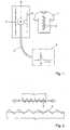
- Figure 1shows an exemplary embodiment of the garment.
- the garment 1comprises a dipole resonator 2 which is adapted to vary its length and/or shape in conformity with the length and/or shape variations of the person and/or animal wearing the garment 1.
- the dipole resonator 2may be attached to the garment 1 or integrated in it, e.g. being part of the garment's textile fibre.
- detection meansare provided which are fit to remotely detect the dipole resonator's resonance frequency.
- the detection meanscomprise a conventional (straight wire) dipole antenna 3 in combination with a reflection analyzer 4, interconnected by a coax cable 5 and a "BALUN" (Balanced/Unbalanced) 6, i.e. a device that connects the asymmetric (coax) cable 5 to the symmetric antenna 3.
- the deviceis completed by a dipole reflector 7.
- the components 3, 6 and 7are integrated in a handheld or standalone device which has to be held at a certain distance of the flexible resonator 2.
- f 0C 0 / ⁇
- Cothe light velocity (3.10 8 m/s).
- Length and/or shape variations of the elastic and/or flexible half wave dipole resonator 2 due to body movementswill result in variations in the resonator's resonance frequency.
- the reflection analyzer 4the corresponding (effective or real) length variations of the half wave dipole resonator 2 can be calculated and thus remote information of the person's body and/or the animal's body movements can be collected remotely.
- the garment 1may contain several resonators 2 and in order to distinguish the various resonators, each resonator may contain additional identification data based on integrated Surface Acoustic Waveguide or Integrated Circuit devices. Such devices may be integrated in or connected to the resonator(s) 2.
- the reflection analyzer 4comprises or is connected to a data processor for processing (computing etc.) the retrieved data.
- Figure 2shows schematically a stretchable dipole comprising a flexible (capable of being bent and/or flexed) and/or elastic dipole element, capable of being stretched and/or expanded between the lengths L1 and L2 (when only capable of being bent and/or flexed, the effective length -i.e. the distance between the resonator's ends- may vary between L1 and L2.
- the constructionis illustrated in Figure 3 .
- the dipole resonatormay comprise flexible and/or elastic support core 8, supporting conductive wire (or string) 9, e.g. wound around the support core 8.
- the dipole resonatorpreferably has the form (and dimensions) of filament.
- the dipole resonator 2 in the embodiments of figure 1preferably consists of a flexible, elastic, stretchable, non-conductive, rubber-like core around which a conductive wire -made of copper, aluminum, metallized foil- is (tightly) wound and attached to the ends of the core.
- the elastic corehas an elasticity approximately equal to an elasticity of the garment at a location near the elastic core.
- elastanesuch as lycra, elaspan, dorlastan or linel are suitable materials from which the elastic core can be formed.
- the windingsmake it possible to stretch (elongate) and release (shorten) the resonator.
- Figure 4Ais a perspective view of a plurality of elastic cores 8 A , 8 B , 8 C and 8 D around which a conductive wiring 9 is woven.
- Figure 4Bis cross-sectional view of the elastic cores shown in Figure 4A .
- the plurality of elastic cores 8 A , 8 B , 8 C and 8 Dmay be applied in a garment according to the present invention.
- the elastic cores 8are, in the example, positioned substantially parallel.
- the conductive wire 9is woven around the elastic cores. In the example shown in Figures 4A and 4B the wire is wound from an upper side of elastic core 8 A to a lower side of elastic core 8 B .
- the wire 9is wound around an upper side of elastic core 8 C and then around a lower side of elastic core 8 D around a right hand side of the elastic core 8 D to a lower side of the elastic core 8 D . From the position of the lower side of the elastic core 8 D , the wire is wound around the lower side of elastic core 8 C .
- the conductive wire 9is thus repeatedly wound around an upper side of a first elastic core and subsequently wound around a lower side of a subsequent elastic core.
- the coreitself may be made of a conductive rubber (e.g. comprising conductive particles).
- the resonatormay be positioned at a suitable location on the garment. For instance, if the garment is a tight-fitting shirt, the resonator may be positioned at a location of the shirt which, in use, presses against the chest of the person and/or the animal wearing the shirt. This way, the breathing frequency of the person and/or the animal can be measured. Alternatively, the resonator may be located at a location of the shirt which, in use, presses against the back of the person and/or animal wearing the shirt. This way, the periodically reoccurring bending of the person's back and/or animal's back may be detected. Of course this type of garment is also suitable for any other application when bending or deforming of an object or a subject is to be measured.
- the resonatormay be located at a location of the trousers which, in use, presses against the front of the knee and/or the back of the knee. Such a location is suitable to measure step frequency during a running excercise.
- a plurality of conductive wirescan be wound around a core as in Figure 3 or woven around a plurality of cores, as in Figures 4A and 4B without deviating from the invention.
Landscapes
- Physics & Mathematics (AREA)
- General Physics & Mathematics (AREA)
- Measurement And Recording Of Electrical Phenomena And Electrical Characteristics Of The Living Body (AREA)
- Measurement Of The Respiration, Hearing Ability, Form, And Blood Characteristics Of Living Organisms (AREA)
- Measurement Of Length, Angles, Or The Like Using Electric Or Magnetic Means (AREA)
- Length Measuring Devices Characterised By Use Of Acoustic Means (AREA)
- Details Of Garments (AREA)
- Testing Of Coins (AREA)
- Undergarments, Swaddling Clothes, Handkerchiefs Or Underwear Materials (AREA)
Abstract
Description
- The invention concerns a tight-fitting garment.
- In e.g. sports and health care it is of growing interest and importance to monitor the human and/or animal condition and physiological performance during their activities. Monitoring means for collecting parameters representative for the human performance are e.g. heart rate sensors, temperature sensors and movement sensors for velocity and acceleration of the body or body parts. More and more, there is an interest to integrate these devices into the clothing (or even the human being itself).
- Length and/or shape displacement and/or position sensors based on mechanical (wire strain gauges) or optical principles (laser) are in general not designed for application in textiles: components are large, heavy, not wireless or contactless and in general they lower the feeling of comfort of the clothing. Besides that, the components are not machine-washable.
FR 2 387 458WO-A-2006 008 325 describes a piece of underwear, which is tight-fitting. It comprises a tag with flexible and elastic dipole resonator. The dipole resonator varies its length and shape in conformity with the piece of underwear, thereby altering the resonator's frequency. The tag can be interrogated by an external detection means, which, for this purpose, must determine the diploe resonator's resonance frequency.- The tight-fitting garment presented hereafter aims to facilitate remote measuring of length and/or shape variations of an object, e.g. a human body, and thus to monitor the condition and/or physiological performance of humans without causing discomfort or hindrance. To that end the garment comprises a dipole resonator which is adapted to vary its length and/or shape in conformity with the length and/or shape variations of a person and/or animal wearing the garment, the length and/or shape of the resonator determining a resonance frequency of the resonator, wherein the resonator is arranged to resonate a detectable signal at the dipole resonator's resonance frequency, wherein the resonator comprises at least one elastic core and a conductive wire supported by the at least one elastic core suitable to elastically deform along with tight-fitting garments. Suitably, the elastic core may comprise, for instance, an elastane, such as lycra, elaspan, dorlastan or linel. Another possibility is that the elastic core comprises a rubber. Due to body movements, length and/or shape variations of the dipole resonator will give varying resonance frequencies which can be measured by the detecting means. By measuring the resonance frequencies the corresponding length and/or shapes variations of the dipole resonator can be computed, resulting in information about the body movements.
- Preferably, the dipole resonator comprises a flexible, i.e. capable of being bent and/or flexed, dipole element: bending or flexing will change the effective length of the dipole and, in consequence, the resonance frequency. Preferably, the dipole element is elastic, i.e. capable of being stretched and/or expanded, by stretching and shrinking the real length of the dipole will change and thus the resonance frequency.
- Pointing to the dipole's preferred embodiments, the dipole resonator preferably comprises flexible and/or elastic support means which support (electrically) conductive means. The dipole resonator preferably has the form of a filament, which can be incorporated in textile, e.g. garments which may be worn upon the relevant human body.
- The dipole resonator may be a half wave dipole resonator. The detection means for remote detection of the dipole resonator's resonance frequency preferably comprises a spectrum analyzer.
Figure 1 shows an exemplary embodiment of the garment according to the invention;Figure 2 shows schematically a stretchable dipole;Figure 3 shows a possible elastic core of the dipole of the garment ofFigure 1 ;Figure 4A is a perspective view of possible elastic cores of the dipole of the garment ofFigure 1 ; andFigure 4B is a cross sectional view of the elastic cores shown inFigure 4A .Figure 1 shows an exemplary embodiment of the garment. Thegarment 1 comprises adipole resonator 2 which is adapted to vary its length and/or shape in conformity with the length and/or shape variations of the person and/or animal wearing thegarment 1. Thedipole resonator 2 may be attached to thegarment 1 or integrated in it, e.g. being part of the garment's textile fibre.- Moreover, detection means are provided which are fit to remotely detect the dipole resonator's resonance frequency. The detection means comprise a conventional (straight wire)
dipole antenna 3 in combination with areflection analyzer 4, interconnected by acoax cable 5 and a "BALUN" (Balanced/Unbalanced) 6, i.e. a device that connects the asymmetric (coax)cable 5 to thesymmetric antenna 3. The device is completed by adipole reflector 7. Thecomponents flexible resonator 2. - If the dipole resonator is a half wave dipole resonator its resonance frequency is f0 = C0 / λ, in which Co is the light velocity (3.108 m/s). Length and/or shape variations of the elastic and/or flexible half
wave dipole resonator 2 due to body movements will result in variations in the resonator's resonance frequency. By monitoring the resonator's resonance frequency by thereflection analyzer 4 the corresponding (effective or real) length variations of the halfwave dipole resonator 2 can be calculated and thus remote information of the person's body and/or the animal's body movements can be collected remotely. - The
garment 1 may containseveral resonators 2 and in order to distinguish the various resonators, each resonator may contain additional identification data based on integrated Surface Acoustic Waveguide or Integrated Circuit devices. Such devices may be integrated in or connected to the resonator(s) 2. Thereflection analyzer 4 comprises or is connected to a data processor for processing (computing etc.) the retrieved data. Figure 2 shows schematically a stretchable dipole comprising a flexible (capable of being bent and/or flexed) and/or elastic dipole element, capable of being stretched and/or expanded between the lengths L1 and L2 (when only capable of being bent and/or flexed, the effective length -i.e. the distance between the resonator's ends- may vary between L1 and L2.- The construction is illustrated in
Figure 3 . The dipole resonator may comprise flexible and/orelastic support core 8, supporting conductive wire (or string) 9, e.g. wound around thesupport core 8. To be able to be integrated in e.g. garments, the dipole resonator preferably has the form (and dimensions) of filament. - Thus, the
dipole resonator 2 in the embodiments offigure 1 preferably consists of a flexible, elastic, stretchable, non-conductive, rubber-like core around which a conductive wire -made of copper, aluminum, metallized foil- is (tightly) wound and attached to the ends of the core. The elastic core has an elasticity approximately equal to an elasticity of the garment at a location near the elastic core. In addition or as an alternative to rubber or rubber-like materials, elastane, such as lycra, elaspan, dorlastan or linel are suitable materials from which the elastic core can be formed. The windings make it possible to stretch (elongate) and release (shorten) the resonator. The diameter of the windings is relatively small in order to consider the wounded dipole as a straight dipole wire with a length of half of the wavelength (L = ½λ). Figure 4A is a perspective view of a plurality ofelastic cores conductive wiring 9 is woven.Figure 4B is cross-sectional view of the elastic cores shown inFigure 4A . The plurality ofelastic cores elastic cores 8 are, in the example, positioned substantially parallel. Theconductive wire 9 is woven around the elastic cores. In the example shown inFigures 4A and 4B the wire is wound from an upper side ofelastic core 8A to a lower side ofelastic core 8B. Then thewire 9 is wound around an upper side ofelastic core 8C and then around a lower side ofelastic core 8D around a right hand side of theelastic core 8D to a lower side of theelastic core 8D. From the position of the lower side of theelastic core 8D, the wire is wound around the lower side ofelastic core 8C. Theconductive wire 9 is thus repeatedly wound around an upper side of a first elastic core and subsequently wound around a lower side of a subsequent elastic core.- Instead winding a conductive wire or string around a non-conductive flexible and/or elastic core, the core itself may be made of a conductive rubber (e.g. comprising conductive particles). Furthermore, the resonator may be positioned at a suitable location on the garment. For instance, if the garment is a tight-fitting shirt, the resonator may be positioned at a location of the shirt which, in use, presses against the chest of the person and/or the animal wearing the shirt. This way, the breathing frequency of the person and/or the animal can be measured. Alternatively, the resonator may be located at a location of the shirt which, in use, presses against the back of the person and/or animal wearing the shirt. This way, the periodically reoccurring bending of the person's back and/or animal's back may be detected. Of course this type of garment is also suitable for any other application when bending or deforming of an object or a subject is to be measured.
- If the garment is a pair of tight-fitting trousers, the resonator may be located at a location of the trousers which, in use, presses against the front of the knee and/or the back of the knee. Such a location is suitable to measure step frequency during a running excercise. Furthermore, although in the Figures only one conductive wire has been shown in each of the examples, a plurality of conductive wires can be wound around a core as in
Figure 3 or woven around a plurality of cores, as inFigures 4A and 4B without deviating from the invention.
Claims (11)
- System comprising a tight-fitting garment (1) comprising a dipole resonator (2) which is adapted to vary its length and/or shape in conformity with the length and/or shape variations when wearing the garment (1), the length and/or shape of the resonator (2) determining a resonance frequency of the resonator (2), wherein the resonator is arranged to resonate a detectable signal at the dipole resonator's resonance frequency, wherein the resonator (2) comprises at least one elastic core (8) and a conductive wire (9) supported by the at least one elastic core (8) suitable to elastically deform along with the garment (1) and detection means (3,4) which are adapted to remotely measure the dipole resonator's resonance frequency.
- System according to claim 1, wherein the elastic core (8) comprises an elastane, such as lycra, elaspan, dorlastan or linel or a rubber.
- System according to claim 1 or 2, wherein the elastic core (8) has an elasticity approximately equal to an elasticity of the garment at a location near the elastic core.
- System according to claim 1, 2 or 3, wherein the dipole resonator (2) comprises a flexible, i.e. capable of being bent and/or flexed, dipole element.
- System according to any one of the preceding claims, wherein the dipole resonator (2) comprises an elastic, i.e. capable of being stretched and/or expanded, dipole element.
- System according to any one of the preceding claims, wherein the dipole resonator (2) has the form of a filament.
- System according to any one of the preceding claims, wherein the dipole resonator (2) is a half wave dipole resonator.
- System according to any one of the preceding claims, wherein said detection means (3,4) for remote detection of the dipole resonator's resonance frequency comprises a reflection analyzer (4).
- System according to any one of the preceding claims, wherein the conductive wire (9) is supported by a plurality of elastic cores (8) suitable to elastically deform along with the tight-fitting garment (1).
- System according to claim 9, wherein the conductive wire (9) is woven around the elastic cores (8), the conductive wire (9) being wound around an upper side of a first elastic core (8) and subsequently wound around a lower side of a subsequent elastic core (8).
- Method for gathering information about body movements using the system of any of claims 1 to 10 by measuring length and/or shape variations of a dipole resonator (2) incorporated in the tight-fitting garment (1) worn upon the body.
Priority Applications (1)
| Application Number | Priority Date | Filing Date | Title |
|---|---|---|---|
| EP06757823AEP1898732B1 (en) | 2005-07-06 | 2006-07-06 | Tight-fitting garment including a sensor for measuring length and / or shape |
Applications Claiming Priority (3)
| Application Number | Priority Date | Filing Date | Title |
|---|---|---|---|
| EP05076562AEP1742013A1 (en) | 2005-07-06 | 2005-07-06 | System for measuring length and/or shape variations of an object |
| EP06757823AEP1898732B1 (en) | 2005-07-06 | 2006-07-06 | Tight-fitting garment including a sensor for measuring length and / or shape |
| PCT/NL2006/000340WO2007004872A1 (en) | 2005-07-06 | 2006-07-06 | Tight-fitting garment including a sensor for measuring length and / or shape |
Publications (2)
| Publication Number | Publication Date |
|---|---|
| EP1898732A1 EP1898732A1 (en) | 2008-03-19 |
| EP1898732B1true EP1898732B1 (en) | 2009-08-26 |
Family
ID=35636702
Family Applications (2)
| Application Number | Title | Priority Date | Filing Date |
|---|---|---|---|
| EP05076562AWithdrawnEP1742013A1 (en) | 2005-07-06 | 2005-07-06 | System for measuring length and/or shape variations of an object |
| EP06757823AActiveEP1898732B1 (en) | 2005-07-06 | 2006-07-06 | Tight-fitting garment including a sensor for measuring length and / or shape |
Family Applications Before (1)
| Application Number | Title | Priority Date | Filing Date |
|---|---|---|---|
| EP05076562AWithdrawnEP1742013A1 (en) | 2005-07-06 | 2005-07-06 | System for measuring length and/or shape variations of an object |
Country Status (5)
| Country | Link |
|---|---|
| US (1) | US7817095B2 (en) |
| EP (2) | EP1742013A1 (en) |
| AT (1) | ATE440512T1 (en) |
| DE (1) | DE602006008784D1 (en) |
| WO (1) | WO2007004872A1 (en) |
Families Citing this family (7)
| Publication number | Priority date | Publication date | Assignee | Title |
|---|---|---|---|---|
| JP6377147B2 (en)* | 2014-05-16 | 2018-08-22 | 国立研究開発法人産業技術総合研究所 | Stretchable conductive circuit and manufacturing method thereof |
| US10758160B2 (en) | 2017-01-20 | 2020-09-01 | Figur8, Inc. | Body part motion analysis with wearable sensors |
| FR3094879B1 (en) | 2019-04-09 | 2022-06-24 | Oreal | Device for illuminating at least one lock of keratinous fibers and associated method |
| EP3972444B1 (en) | 2019-05-21 | 2023-06-07 | L'oreal | Foil for a strand of keratinic fibers and related kit and illumination process |
| CN111855048B (en)* | 2020-07-20 | 2021-05-11 | 上海交通大学 | Acoustic waveguide-based sensor and method of making the same |
| KR102433218B1 (en)* | 2020-11-18 | 2022-08-18 | (주)빅라인 | Flexible type mast apparatus combined with antenna made of fiber reinforced plastic and its manufacturing method |
| JP7606373B2 (en)* | 2021-03-16 | 2024-12-25 | キヤノンメディカルシステムズ株式会社 | Vital Information Monitor and Magnetic Resonance Imaging Apparatus |
Family Cites Families (15)
| Publication number | Priority date | Publication date | Assignee | Title |
|---|---|---|---|---|
| FR2204296A5 (en)* | 1972-10-23 | 1974-05-17 | Nle Indle Aerospatia Soc | |
| FR2387458A1 (en)* | 1977-04-15 | 1978-11-10 | Duhamel Leon | Detector for person buried in e.g. snow avalanche - has transmitting dipole aerial woven in sleeves of over-garment and connected to Hartley oscillator |
| DE19744527A1 (en)* | 1997-10-09 | 1999-04-15 | Innocept Medizintechnik Gmbh | Elastomeric insulated cable produced by co-extrusion |
| GB0002935D0 (en)* | 2000-02-10 | 2000-03-29 | Koninkl Philips Electronics Nv | Portable device antenna |
| US6677917B2 (en)* | 2002-02-25 | 2004-01-13 | Koninklijke Philips Electronics N.V. | Fabric antenna for tags |
| AU2003245761A1 (en)* | 2002-07-01 | 2004-01-19 | University Of Manitoba | Measuring strain in a structure (bridge) with a (temperature compensated) electromagnetic resonator (microwave cavity) |
| JP4255048B2 (en)* | 2002-08-02 | 2009-04-15 | 横浜ゴム株式会社 | Tire strain state detection method, strain state detection device, sensor unit thereof, and tire including the same |
| CN100523341C (en)* | 2002-09-14 | 2009-08-05 | W·齐默尔曼两合公司 | conductive yarn |
| US20040102116A1 (en)* | 2002-11-25 | 2004-05-27 | Milliken & Company | Electrostatic dissipating fabric and garments formed therefrom |
| US6867740B2 (en)* | 2003-05-30 | 2005-03-15 | Human-Animal Biotelemetry Instrumentation-Technology Research Ltd. | Portable antenna |
| FR2858758B1 (en)* | 2003-08-14 | 2006-04-07 | Tam Telesante Sarl | MEDICAL MONITORING SYSTEM USING A CLOTHING |
| ES2219199A1 (en)* | 2004-06-21 | 2004-11-16 | Vives Vidal, Vivesa, S.A. | Transmitting and/or receiving device which can be applied to garments and garment thus obtained |
| US7337810B2 (en)* | 2005-04-07 | 2008-03-04 | Woven Electronics Corporation | Elastic fabric with sinusoidally disposed wires |
| US20060281382A1 (en)* | 2005-06-10 | 2006-12-14 | Eleni Karayianni | Surface functional electro-textile with functionality modulation capability, methods for making the same, and applications incorporating the same |
| WO2007004782A1 (en) | 2005-07-04 | 2007-01-11 | Oh Su Kim | Pad conditioner and error detecting apparatus for the same |
- 2005
- 2005-07-06EPEP05076562Apatent/EP1742013A1/ennot_activeWithdrawn
- 2006
- 2006-07-06USUS11/994,622patent/US7817095B2/enactiveActive
- 2006-07-06DEDE602006008784Tpatent/DE602006008784D1/enactiveActive
- 2006-07-06WOPCT/NL2006/000340patent/WO2007004872A1/enactiveApplication Filing
- 2006-07-06ATAT06757823Tpatent/ATE440512T1/ennot_activeIP Right Cessation
- 2006-07-06EPEP06757823Apatent/EP1898732B1/enactiveActive
Also Published As
| Publication number | Publication date |
|---|---|
| US20080224934A1 (en) | 2008-09-18 |
| DE602006008784D1 (en) | 2009-10-08 |
| ATE440512T1 (en) | 2009-09-15 |
| EP1898732A1 (en) | 2008-03-19 |
| EP1742013A1 (en) | 2007-01-10 |
| US7817095B2 (en) | 2010-10-19 |
| WO2007004872A1 (en) | 2007-01-11 |
Similar Documents
| Publication | Publication Date | Title |
|---|---|---|
| EP1898732B1 (en) | Tight-fitting garment including a sensor for measuring length and / or shape | |
| EP2531104B1 (en) | Method, device and system for measuring torsion or bending at a joint between two limbs | |
| CN101854856B (en) | Clothing article for detecting breathing movement | |
| EP2180091B1 (en) | Pressure-sensitive conductive yarn and biological information-measuring garment | |
| EP1659940B1 (en) | Physiological monitoring garment | |
| CN101248989B (en) | A monitoring system for physiological parameters | |
| EP1508298B1 (en) | Heartbeat detection device | |
| EP2581701A1 (en) | An apparatus for determining a dimension of a selected surface of an object | |
| EP2228007A1 (en) | Cloth comprising separable sensitive areas | |
| US20160150982A1 (en) | Wearable respiratory inductance plethysmography device and method for respiratory activity analysis | |
| EP3238621B1 (en) | Wearable step counter system | |
| US20130197387A1 (en) | System and Method for Measuring Movement of a Body Part | |
| US9932697B2 (en) | Structure and method for connecting fabric sensor and digital yarn | |
| FR2858758B1 (en) | MEDICAL MONITORING SYSTEM USING A CLOTHING | |
| WO2014207653A1 (en) | Wearable device for measuring body dimensions | |
| WO2018159062A1 (en) | Size measurement device and size measurement system | |
| US20180336774A1 (en) | Smart garments that identify user changes | |
| US20100225476A1 (en) | Patch for detecting movements of a body | |
| JP3978453B2 (en) | Animal biosignal detection device | |
| KR102528997B1 (en) | Gloves with integral voltage detector | |
| WO2011054548A1 (en) | Respiration measurement sensor | |
| GB2500000A (en) | Microwave monitoring using an electrically conductive textile | |
| CN205214311U (en) | Intelligent waistband to working clan | |
| Pei et al. | Wearable antenna design for bioinformation | |
| JPWO2020148829A1 (en) | Sensor materials, sensor elements, clothing, measuring devices, monitoring systems, and programs |
Legal Events
| Date | Code | Title | Description |
|---|---|---|---|
| PUAI | Public reference made under article 153(3) epc to a published international application that has entered the european phase | Free format text:ORIGINAL CODE: 0009012 | |
| 17P | Request for examination filed | Effective date:20080108 | |
| AK | Designated contracting states | Kind code of ref document:A1 Designated state(s):AT BE BG CH CY CZ DE DK EE ES FI FR GB GR HU IE IS IT LI LT LU LV MC NL PL PT RO SE SI SK TR | |
| DAX | Request for extension of the european patent (deleted) | ||
| 17Q | First examination report despatched | Effective date:20080328 | |
| R17C | First examination report despatched (corrected) | Effective date:20080411 | |
| GRAP | Despatch of communication of intention to grant a patent | Free format text:ORIGINAL CODE: EPIDOSNIGR1 | |
| GRAS | Grant fee paid | Free format text:ORIGINAL CODE: EPIDOSNIGR3 | |
| GRAA | (expected) grant | Free format text:ORIGINAL CODE: 0009210 | |
| AK | Designated contracting states | Kind code of ref document:B1 Designated state(s):AT BE BG CH CY CZ DE DK EE ES FI FR GB GR HU IE IS IT LI LT LU LV MC NL PL PT RO SE SI SK TR | |
| REG | Reference to a national code | Ref country code:GB Ref legal event code:FG4D | |
| REG | Reference to a national code | Ref country code:CH Ref legal event code:EP | |
| REG | Reference to a national code | Ref country code:IE Ref legal event code:FG4D | |
| REF | Corresponds to: | Ref document number:602006008784 Country of ref document:DE Date of ref document:20091008 Kind code of ref document:P | |
| LTIE | Lt: invalidation of european patent or patent extension | Effective date:20090826 | |
| PG25 | Lapsed in a contracting state [announced via postgrant information from national office to epo] | Ref country code:SE Free format text:LAPSE BECAUSE OF FAILURE TO SUBMIT A TRANSLATION OF THE DESCRIPTION OR TO PAY THE FEE WITHIN THE PRESCRIBED TIME-LIMIT Effective date:20090826 Ref country code:LT Free format text:LAPSE BECAUSE OF FAILURE TO SUBMIT A TRANSLATION OF THE DESCRIPTION OR TO PAY THE FEE WITHIN THE PRESCRIBED TIME-LIMIT Effective date:20090826 Ref country code:IS Free format text:LAPSE BECAUSE OF FAILURE TO SUBMIT A TRANSLATION OF THE DESCRIPTION OR TO PAY THE FEE WITHIN THE PRESCRIBED TIME-LIMIT Effective date:20091226 Ref country code:FI Free format text:LAPSE BECAUSE OF FAILURE TO SUBMIT A TRANSLATION OF THE DESCRIPTION OR TO PAY THE FEE WITHIN THE PRESCRIBED TIME-LIMIT Effective date:20090826 Ref country code:AT Free format text:LAPSE BECAUSE OF FAILURE TO SUBMIT A TRANSLATION OF THE DESCRIPTION OR TO PAY THE FEE WITHIN THE PRESCRIBED TIME-LIMIT Effective date:20090826 | |
| PG25 | Lapsed in a contracting state [announced via postgrant information from national office to epo] | Ref country code:PL Free format text:LAPSE BECAUSE OF FAILURE TO SUBMIT A TRANSLATION OF THE DESCRIPTION OR TO PAY THE FEE WITHIN THE PRESCRIBED TIME-LIMIT Effective date:20090826 Ref country code:LV Free format text:LAPSE BECAUSE OF FAILURE TO SUBMIT A TRANSLATION OF THE DESCRIPTION OR TO PAY THE FEE WITHIN THE PRESCRIBED TIME-LIMIT Effective date:20090826 Ref country code:SI Free format text:LAPSE BECAUSE OF FAILURE TO SUBMIT A TRANSLATION OF THE DESCRIPTION OR TO PAY THE FEE WITHIN THE PRESCRIBED TIME-LIMIT Effective date:20090826 | |
| PG25 | Lapsed in a contracting state [announced via postgrant information from national office to epo] | Ref country code:CY Free format text:LAPSE BECAUSE OF FAILURE TO SUBMIT A TRANSLATION OF THE DESCRIPTION OR TO PAY THE FEE WITHIN THE PRESCRIBED TIME-LIMIT Effective date:20090826 Ref country code:BG Free format text:LAPSE BECAUSE OF FAILURE TO SUBMIT A TRANSLATION OF THE DESCRIPTION OR TO PAY THE FEE WITHIN THE PRESCRIBED TIME-LIMIT Effective date:20091126 Ref country code:PT Free format text:LAPSE BECAUSE OF FAILURE TO SUBMIT A TRANSLATION OF THE DESCRIPTION OR TO PAY THE FEE WITHIN THE PRESCRIBED TIME-LIMIT Effective date:20091228 | |
| PG25 | Lapsed in a contracting state [announced via postgrant information from national office to epo] | Ref country code:RO Free format text:LAPSE BECAUSE OF FAILURE TO SUBMIT A TRANSLATION OF THE DESCRIPTION OR TO PAY THE FEE WITHIN THE PRESCRIBED TIME-LIMIT Effective date:20090826 Ref country code:ES Free format text:LAPSE BECAUSE OF FAILURE TO SUBMIT A TRANSLATION OF THE DESCRIPTION OR TO PAY THE FEE WITHIN THE PRESCRIBED TIME-LIMIT Effective date:20091207 Ref country code:EE Free format text:LAPSE BECAUSE OF FAILURE TO SUBMIT A TRANSLATION OF THE DESCRIPTION OR TO PAY THE FEE WITHIN THE PRESCRIBED TIME-LIMIT Effective date:20090826 Ref country code:DK Free format text:LAPSE BECAUSE OF FAILURE TO SUBMIT A TRANSLATION OF THE DESCRIPTION OR TO PAY THE FEE WITHIN THE PRESCRIBED TIME-LIMIT Effective date:20090826 Ref country code:CZ Free format text:LAPSE BECAUSE OF FAILURE TO SUBMIT A TRANSLATION OF THE DESCRIPTION OR TO PAY THE FEE WITHIN THE PRESCRIBED TIME-LIMIT Effective date:20090826 | |
| PG25 | Lapsed in a contracting state [announced via postgrant information from national office to epo] | Ref country code:SK Free format text:LAPSE BECAUSE OF FAILURE TO SUBMIT A TRANSLATION OF THE DESCRIPTION OR TO PAY THE FEE WITHIN THE PRESCRIBED TIME-LIMIT Effective date:20090826 | |
| PG25 | Lapsed in a contracting state [announced via postgrant information from national office to epo] | Ref country code:BE Free format text:LAPSE BECAUSE OF FAILURE TO SUBMIT A TRANSLATION OF THE DESCRIPTION OR TO PAY THE FEE WITHIN THE PRESCRIBED TIME-LIMIT Effective date:20090826 | |
| PLBE | No opposition filed within time limit | Free format text:ORIGINAL CODE: 0009261 | |
| STAA | Information on the status of an ep patent application or granted ep patent | Free format text:STATUS: NO OPPOSITION FILED WITHIN TIME LIMIT | |
| 26N | No opposition filed | Effective date:20100527 | |
| PG25 | Lapsed in a contracting state [announced via postgrant information from national office to epo] | Ref country code:GR Free format text:LAPSE BECAUSE OF FAILURE TO SUBMIT A TRANSLATION OF THE DESCRIPTION OR TO PAY THE FEE WITHIN THE PRESCRIBED TIME-LIMIT Effective date:20091127 | |
| PG25 | Lapsed in a contracting state [announced via postgrant information from national office to epo] | Ref country code:MC Free format text:LAPSE BECAUSE OF NON-PAYMENT OF DUE FEES Effective date:20100731 | |
| REG | Reference to a national code | Ref country code:CH Ref legal event code:PL | |
| PG25 | Lapsed in a contracting state [announced via postgrant information from national office to epo] | Ref country code:CH Free format text:LAPSE BECAUSE OF NON-PAYMENT OF DUE FEES Effective date:20100731 Ref country code:LI Free format text:LAPSE BECAUSE OF NON-PAYMENT OF DUE FEES Effective date:20100731 | |
| PG25 | Lapsed in a contracting state [announced via postgrant information from national office to epo] | Ref country code:IE Free format text:LAPSE BECAUSE OF NON-PAYMENT OF DUE FEES Effective date:20100706 | |
| PG25 | Lapsed in a contracting state [announced via postgrant information from national office to epo] | Ref country code:HU Free format text:LAPSE BECAUSE OF FAILURE TO SUBMIT A TRANSLATION OF THE DESCRIPTION OR TO PAY THE FEE WITHIN THE PRESCRIBED TIME-LIMIT Effective date:20100227 Ref country code:LU Free format text:LAPSE BECAUSE OF NON-PAYMENT OF DUE FEES Effective date:20100706 | |
| PG25 | Lapsed in a contracting state [announced via postgrant information from national office to epo] | Ref country code:TR Free format text:LAPSE BECAUSE OF FAILURE TO SUBMIT A TRANSLATION OF THE DESCRIPTION OR TO PAY THE FEE WITHIN THE PRESCRIBED TIME-LIMIT Effective date:20090826 | |
| REG | Reference to a national code | Ref country code:FR Ref legal event code:PLFP Year of fee payment:11 | |
| REG | Reference to a national code | Ref country code:FR Ref legal event code:PLFP Year of fee payment:12 | |
| REG | Reference to a national code | Ref country code:FR Ref legal event code:PLFP Year of fee payment:13 | |
| P01 | Opt-out of the competence of the unified patent court (upc) registered | Effective date:20230522 | |
| PGFP | Annual fee paid to national office [announced via postgrant information from national office to epo] | Ref country code:DE Payment date:20240719 Year of fee payment:19 | |
| PGFP | Annual fee paid to national office [announced via postgrant information from national office to epo] | Ref country code:GB Payment date:20240722 Year of fee payment:19 | |
| PGFP | Annual fee paid to national office [announced via postgrant information from national office to epo] | Ref country code:FR Payment date:20240729 Year of fee payment:19 | |
| PGFP | Annual fee paid to national office [announced via postgrant information from national office to epo] | Ref country code:IT Payment date:20240725 Year of fee payment:19 | |
| PGFP | Annual fee paid to national office [announced via postgrant information from national office to epo] | Ref country code:NL Payment date:20250721 Year of fee payment:20 |