EP1897568B1 - Surgical system - Google Patents
Surgical systemDownload PDFInfo
- Publication number
- EP1897568B1 EP1897568B1EP07014369AEP07014369AEP1897568B1EP 1897568 B1EP1897568 B1EP 1897568B1EP 07014369 AEP07014369 AEP 07014369AEP 07014369 AEP07014369 AEP 07014369AEP 1897568 B1EP1897568 B1EP 1897568B1
- Authority
- EP
- European Patent Office
- Prior art keywords
- fluid
- line
- aspiration
- fluid container
- container
- Prior art date
- Legal status (The legal status is an assumption and is not a legal conclusion. Google has not performed a legal analysis and makes no representation as to the accuracy of the status listed.)
- Active
Links
- 239000012530fluidSubstances0.000claimsdescription153
- 230000002262irrigationEffects0.000claimsdescription40
- 238000003973irrigationMethods0.000claimsdescription40
- 238000009423ventilationMethods0.000claimsdescription17
- 238000013022ventingMethods0.000claimsdescription9
- 238000000034methodMethods0.000claimsdescription6
- 239000000126substanceSubstances0.000claimsdescription3
- 239000012634fragmentSubstances0.000description7
- 238000011109contaminationMethods0.000description6
- 239000003570airSubstances0.000description5
- 210000002159anterior chamberAnatomy0.000description4
- 238000000926separation methodMethods0.000description4
- 208000002177CataractDiseases0.000description3
- 230000007423decreaseEffects0.000description3
- 239000000243solutionSubstances0.000description3
- 238000004026adhesive bondingMethods0.000description1
- 238000005273aerationMethods0.000description1
- 239000012080ambient airSubstances0.000description1
- 238000000071blow mouldingMethods0.000description1
- 239000007767bonding agentSubstances0.000description1
- 239000003638chemical reducing agentSubstances0.000description1
- 150000001875compoundsChemical class0.000description1
- 230000001687destabilizationEffects0.000description1
- 238000001514detection methodMethods0.000description1
- 238000011161developmentMethods0.000description1
- 230000018109developmental processEffects0.000description1
- 238000010586diagramMethods0.000description1
- 238000007599dischargingMethods0.000description1
- 239000003814drugSubstances0.000description1
- 230000000694effectsEffects0.000description1
- 230000005284excitationEffects0.000description1
- 238000001125extrusionMethods0.000description1
- 239000011521glassSubstances0.000description1
- 239000012535impuritySubstances0.000description1
- 238000001746injection mouldingMethods0.000description1
- 238000009434installationMethods0.000description1
- 238000004519manufacturing processMethods0.000description1
- 239000002245particleSubstances0.000description1
- 239000004033plasticSubstances0.000description1
- 229920003023plasticPolymers0.000description1
- 238000006068polycondensation reactionMethods0.000description1
- 238000006116polymerization reactionMethods0.000description1
- 238000001356surgical procedureMethods0.000description1
- 238000002604ultrasonographyMethods0.000description1
- 238000003466weldingMethods0.000description1
Images


Classifications
- A—HUMAN NECESSITIES
- A61—MEDICAL OR VETERINARY SCIENCE; HYGIENE
- A61M—DEVICES FOR INTRODUCING MEDIA INTO, OR ONTO, THE BODY; DEVICES FOR TRANSDUCING BODY MEDIA OR FOR TAKING MEDIA FROM THE BODY; DEVICES FOR PRODUCING OR ENDING SLEEP OR STUPOR
- A61M1/00—Suction or pumping devices for medical purposes; Devices for carrying-off, for treatment of, or for carrying-over, body-liquids; Drainage systems
- A61M1/71—Suction drainage systems
- A61M1/74—Suction control
- A—HUMAN NECESSITIES
- A61—MEDICAL OR VETERINARY SCIENCE; HYGIENE
- A61M—DEVICES FOR INTRODUCING MEDIA INTO, OR ONTO, THE BODY; DEVICES FOR TRANSDUCING BODY MEDIA OR FOR TAKING MEDIA FROM THE BODY; DEVICES FOR PRODUCING OR ENDING SLEEP OR STUPOR
- A61M1/00—Suction or pumping devices for medical purposes; Devices for carrying-off, for treatment of, or for carrying-over, body-liquids; Drainage systems
- A61M1/71—Suction drainage systems
- A61M1/77—Suction-irrigation systems
Definitions
- the inventionrelates to a surgical system for controlling fluid in the treatment of a cataract with the phacoemulsification technique.
- cataractsThere are several surgical techniques for treating cataracts, which are referred to in medicine as cataracts.
- the most common techniqueis phacoemulsification, in which a thin tip is inserted into the diseased lens and excited to vibrate with ultrasound. The vibrating tip emulsifies the lens in its immediate vicinity so that the resulting lens fragments can be aspirated from a pump through a conduit. Once the lens has been completely emulsified, a new artificial lens can be inserted into the empty capsular bag so that a patient treated in this way can regain good vision.
- a deviceIn phacoemulsification, a device is used which generally has a vibratory tip in a handpiece, a rinse line (irrigation line) for supplying rinse fluid to the lens to be treated, and a suction line (aspiration line) for carrying emulsified lens fragments into a collection container.
- a lens fragmentmay clog the entrance area of the handpiece tip.
- a vacuumbuilds up downstream in the aspiration line. For example, with continued ultrasonic vibration of the tip, the lens fragment can break up into smaller segments, thereby abruptly stopping the occlusion.
- the built-up negative pressure in the aspiration linecauses such a occlusion breakthrough in a very short time, a relatively large amount of fluid is sucked out of the eye. This can result in collapse of the anterior chamber of the eye. It is possible that the capsular bag is pulled to the handpiece tip and pierced by the tip. In addition to such a violation of the capsular bag can also cause a too deep penetrated tip damage to the behind the capsular bag eye glass body.
- Another possibilityis to carry out a pressure equalization by means of ambient air. Air at atmospheric pressure is introduced into the aspiration line. It is advantageous that there is no excitation of a pressure fluctuation in the irrigation line. However, the introduced into the aspiration line air changes the fluidic properties of the intake system, so that the air must be pumped out of the aspiration line in order to achieve a dynamic suction pressure curve in the aspiration line again.
- the fluid control system of the present inventioncomprises an irrigation conduit connected at one end to a first fluid container for receiving irrigation fluid and at another end to a surgical handpiece, a suction pump, an aspiration input conduit extending from the surgical handpiece to a surgical handpiece Input of the suction pump is provided so that can suck from the suction pump fluid through the handpiece, a pressure sensor which detects the fluid pressure in the Aspirationseingangstechnisch, an Aspirationsausgangs ein which connects an output of the suction pump with a collecting container so that fluid from the output of Suction pump can be fed into the collecting container, a second fluid container for receiving irrigation fluid, an aspiration ventilation line, which connects the second fluid container with the aspiration input line, and a vent valve, which in the aspiration ventilation line v orsee and can be switched depending on the fluid pressure in the Aspirationseingangs effet.
- fluidcan be guided out of the second fluid container through the aspiration ventilation line into the aspiration input line with the system according to the invention. If, for example, after an occlusion breakthrough, the vacuum pressure in the aspiration line increases again in the direction of the normal suction pressure, the ventilation line can be correspondingly released by the ventilation valve, so that rapid pressure equalization is possible and a drop in the suction pressure to too high a value is avoided.
- the supplied fluiddoes not come from the first fluid container which contains the irrigation fluid and is connected to the irrigation line. Through the second fluid container, a complete separation of this first fluid container is achieved, so that during the venting no pressure fluctuations in the irrigation line can be excited.
- contamination of the irrigation lineis excluded by the separation of the two fluid containers. Since the second fluid container contains sterile fluid, a contamination of the aspiration line by venting is also excluded. Thus, it is possible to use the surgical system even without risk of contamination with previously used impurities in several patients to be treated consecutively.
- the second fluid containercan be filled by a filling line, which has a filling valve, wherein the filling line is connected at one end to the irrigation line.
- a filling linewhich has a filling valve, wherein the filling line is connected at one end to the irrigation line.
- the filling lineis connected at one end to the irrigation line.
- the filling valveBy the filling valve, a reliable separation between the irrigation line and the part of the filling line is achieved, which faces the second fluid container.
- the other end of the fill lineterminates at a predetermined distance from a maximum fluid level height of the second fluid container so that there is no direct contact between the other end of the fill line and the fluid in the second fluid container. This can even more reliably prevent contamination of the irrigation line.
- a decrease in the fluid levelcan be detected after venting the aspiration input line and a refilling of the second fluid container can be initiated at a suitable time.
- the second fluid containercan be connected to an overflow line, through which excess fluid can be diverted into an additional container.
- irrigation and aspiration lines and the fluid containerare used only for one patient, the risk of contamination of the second fluid container is lower, so that in another embodiment it may be provided to connect the filling line to the second fluid container at the other end.
- Such a connection between the other end and the second fluid containeris obtainable by mechanical or chemical connection means or by a thermal connection method. It may, for example, involve clamping, gluing, welding and, in particular, plastics, by means of polymerization or polycondensation.
- the filling lineis connected to the second fluid container, it is possible to form a closed system. If fluid is discharged from the second fluid container, a pressure equalization must take place within the second fluid container. According to a preferred embodiment, this can be achieved in that the second fluid container has a wall with at least one elastically deformable region. The reduction in the amount of fluid within the second fluid container then leads to a deformation of the elastic region, so that no compressed air or the like must be tracked in the second fluid container. This makes the system relatively easy to operate.
- the second fluid containeris tubular, for example, formed as a hose such as the filling line or Aspirationsbe Kunststoffungs Koch, whereby a cost-effective and easy to implement solution is achieved.
- the hosealso has the advantage that it is elastically deformable not only in a limited area but along its entire circumference.
- the filling line, the second fluid container and the aspiration ventilation lineare integrally formed, so that an easy installation in a cassette is achieved.
- the irrigation linehas an irrigation valve, this can be brought into such a position that the irrigation line is interrupted.
- a filling of the second fluid container with fluid from the first fluid containercan then be carried out particularly cleverly by means of the filling line when the irrigation valve is arranged in the irrigation line between the handpiece and the filling line. In this case, occur during filling of the second fluid container no pressure fluctuations in the part of the irrigation line, which is arranged between Irrigationsventil and handpiece. This ensures that during the filling of the second fluid container in the eye no pressure fluctuations are induced.
- fluidis derivable from the aspiration vent line at the bottom or near the bottom of the second fluid container. This ensures that the maximum available amount of aeration fluid can always be made available and, in addition, no air is supplied to the aspiration input line when the container is filled.
- the pressure sensordetects the fluid pressure in the aspiration line near the handpiece.
- the pressure sensordetects the fluid pressure in the aspiration line near the handpiece.
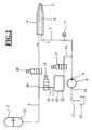
- a schematic representation of an embodiment of the inventive surgical system 1is shown.
- an irrigation fluid 21is contained, which can be passed via an irrigation line 3 to a surgical handpiece 4.
- the handpiece 4may be a handpiece for Phacoemulsification act in which a vibrating tip 5 emulsifies a clouded lens of an eye and sucked the smashed lens fragments.
- An irrigation valve 40which in the illustration in Fig. 1 2-way valve allows passage of the irrigation fluid toward the handpiece 4. From the tip 5, an aspiration line 6 extends to one end of the handpiece 4 to carry emulsified lens parts and fluid out of the eye.
- the removalis caused by a suction pump 8, which is connected at its input 9 via an aspiration input line 7 with the handpiece 4.
- a fluid pressure in the aspiration input line 7is detected by a pressure sensor 11 arranged between the inlet 9 of the suction pump 8 and the handpiece 4.
- the pressure sensor 11is provided in the vicinity of the handpiece 4, so that a pressure change in the region of the tip 5 can be detected after a short distance through the handpiece 4. An even faster detection of a change in pressure is achieved when the pressure sensor 11 detects the fluid pressure in the aspiration line 6 within the handpiece 4.
- the aspiration line 6can be understood in this case as the front portion of the aspiration input line 7.
- the suction pump 8forwards the linsing fragments and fluid at its exit through an aspiration output line 12 into a collecting container 13.
- an aspiration vent line 14is connected, which is connected to a second fluid container 15.
- a fluid 22is contained, which can be supplied to the aspiration input line 7 with a corresponding position of a provided in the aspiration ventilation line 14 2-way vent valve 17.
- the second fluid container 15is filled with a fluid 22, which at the in Fig. 1 embodiment shown by a filling line 18 is supplied.
- a 2-way filling valve 19is provided, which blocks or releases the fluid passage.
- the filling line 18is connected at one end 30 to the irrigation line 3, so that fluid 21 can be fed into the filling line 18.
- the other end 31 of the filling line 18terminates at a predetermined distance 20 from the maximum fluid level height of the second fluid container 15, so that there is no direct contact between the other end 31 of the filling line 18 and the fluid 22 in the second fluid container 15.
- the second fluid container 15is provided with a sensor 16 with which the fluid level in the second fluid container 15 can be detected.
- the sensor 16ensures that the filling of the second fluid container 15 takes place only until the maximum permissible fluid level is reached.
- the fluid container 15still has an overflow with an overflow line 23, through which excess fluid can be passed into a container 24.
- the containers 24 and 13may be integrally formed.
- the second fluid container 15 'is a closed container, wherein the other end 31 of the filling line 18 is connected to the second fluid container 15'.
- a pressure equalization within the containermust be provided. This can be achieved, for example, by providing a wall of the second fluid container 15 'with at least one elastically deformable region.
- This elastically deformable regionmay be a flexible lid on a rigid fluid container 15 'or a flexible sidewall.
- the entire second fluid container 15 'is formed elastically deformable, for example as a hose or bag.
- the elastically deformable region of the second fluid container 15'contracts, reducing the volume of fluid within the second fluid container 15 '.
- the second embodiment of the in Fig. 2The surgical system shown differs from that in Fig. 1 illustrated first embodiment, inter alia, characterized in that for the second fluid container 15 ', a pressure compensation by z. B. atmospheric pressure is not required.
- the level-of-level sensor 16may be used as shown in FIG Fig. 1 shown provided first embodiment of the surgical system can be dispensed with. This also applies to the overflow line 23 for discharging excess fluid into the container 24.
- a fluid container 15 'arewith at least one elastically deformable region.
- the compoundcan be achieved by mechanical or chemical bonding agents or by a thermal bonding method.
- the fluid container 15 'thusconstitutes a diameter-widened central portion of the conduits 18 and 14 Fig. 3B
- the second fluid container 15 'is a tube piece with diameters tapered at the ends and connected to the lines 18 and 14 are connected while at the in Fig. 3C illustrated form an additional hose with associated reducers 32 is provided.
- the manufacture of the fluid container 15 'cantake place, for example, by extrusion, blow molding or an injection molding process.
- the pressure sensor 11detects an increase in the vacuum pressure in the direction of the atmospheric pressure in the aspiration input line 7. Thereafter, the vent valve 17 is moved to a position such that the aspiration vent line is enabled and fluid 22 can be directed from the second fluid container 15, 15 'to the aspiration input line 7.
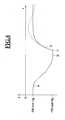
- Fig. 4the effect of this ventilation process is shown by means of a graph.
- the diagramshows a pressure curve in an aspiration line 6 or 7 as a function of time. From the usual suction pressure in the height of about -300 mm Hg increases after occurrence of an occlusion, event "A", the suction pressure in the aspiration line steadily until a maximum vacuum pressure is reached, event "B".
Landscapes
- Health & Medical Sciences (AREA)
- Heart & Thoracic Surgery (AREA)
- Biomedical Technology (AREA)
- Vascular Medicine (AREA)
- Engineering & Computer Science (AREA)
- Anesthesiology (AREA)
- Hematology (AREA)
- Life Sciences & Earth Sciences (AREA)
- Animal Behavior & Ethology (AREA)
- General Health & Medical Sciences (AREA)
- Public Health (AREA)
- Veterinary Medicine (AREA)
- Pulmonology (AREA)
- External Artificial Organs (AREA)
- Infusion, Injection, And Reservoir Apparatuses (AREA)
Description
Translated fromGermanDie Erfindung betrifft ein chirurgisches System zur Steuerung von Fluid bei der Behandlung eines Kataraktes mit der Phakoemulsifikationstechnik.The invention relates to a surgical system for controlling fluid in the treatment of a cataract with the phacoemulsification technique.
Zur Behandlung einer Linsentrübung, welche in der Medizin als Grauer Star bezeichnet wird, gibt es mehrere chirurgische Techniken. Die am weitesten verbreitete Technik ist die Phakoemulsifikation, bei der eine dünne Spitze in die erkrankte Linse eingeführt und mit Ultraschall zu Schwingungen angeregt wird. Die vibrierende Spitze emulsifiziert in ihrer nächsten Umgebung die Linse derart, dass die entstehenden Linsenfragmente durch eine Leitung von einer Pumpe abgesaugt werden können. Ist die Linse vollständig emulsifiziert worden, kann in den leeren Kapselsack eine neue künstliche Linse eingesetzt werden, so dass ein derart behandelter Patient wieder ein gutes Sehvermögen erreichen kann.There are several surgical techniques for treating cataracts, which are referred to in medicine as cataracts. The most common technique is phacoemulsification, in which a thin tip is inserted into the diseased lens and excited to vibrate with ultrasound. The vibrating tip emulsifies the lens in its immediate vicinity so that the resulting lens fragments can be aspirated from a pump through a conduit. Once the lens has been completely emulsified, a new artificial lens can be inserted into the empty capsular bag so that a patient treated in this way can regain good vision.
Bei der Phakoemulsifikation kommt eine Vorrichtung zum Einsatz, welche allgemein eine schwingfähige Spitze in einem Handstück, eine Spülleitung (Irrigationsleitung) für die Zufuhr von Spülfluid zu der zu behandelnden Linse und eine Saugleitung (Aspirationsleitung) zum Abtransportieren emulsifizierter Linsenfragmente in einen Sammelbehälter aufweist. Während des Abtransportierens in den Sammelbehälter kann es vorkommen, dass ein Linsenfragment den Eingangsbereich der Handstückspitze verstopft. Bei kontinuierlich laufender Saugpumpe baut sich somit stromabwärts in der Aspirationsleitung ein Vakuum auf. Durch zum Beispiel fortgesetzte Ultraschallschwingungen der Spitze kann das Linsenfragment in kleinere Segmente zerbrechen, wodurch die Verstopfung (Okklusion) schlagartig beendet ist. Der aufgebaute Unterdruck in der Aspirationsleitung führt dazu, dass bei einem solchen Okklusionsdurchbruch in sehr kurzer Zeit eine relativ große Fluidmenge aus dem Auge gesaugt wird. Dies kann zur Folge haben, dass ein Kollaps der Augenvorderkammer eintritt. Es ist dabei möglich, dass der Kapselsack zur Handstückspitze gezogen und von der Spitze durchstochen wird. Neben einer solchen Verletzung des Kapselsackes kann ferner eine zu tief eingedrungene Spitze eine Beschädigung des hinter dem Kapselsack liegenden Augen-Glaskörpers bewirken.In phacoemulsification, a device is used which generally has a vibratory tip in a handpiece, a rinse line (irrigation line) for supplying rinse fluid to the lens to be treated, and a suction line (aspiration line) for carrying emulsified lens fragments into a collection container. During removal into the collection container, a lens fragment may clog the entrance area of the handpiece tip. With a continuously running suction pump, a vacuum builds up downstream in the aspiration line. For example, with continued ultrasonic vibration of the tip, the lens fragment can break up into smaller segments, thereby abruptly stopping the occlusion. The built-up negative pressure in the aspiration line causes such a occlusion breakthrough in a very short time, a relatively large amount of fluid is sucked out of the eye. This can result in collapse of the anterior chamber of the eye. It is possible that the capsular bag is pulled to the handpiece tip and pierced by the tip. In addition to such a violation of the capsular bag can also cause a too deep penetrated tip damage to the behind the capsular bag eye glass body.
Im Stand der Technik werden verschiedene Lösungen vorgeschlagen, um bei einem Okklusionsdurchbruch einen Kollaps der Augenvorderkammer zu vermeiden. In
Eine andere Möglichkeit besteht darin, einen Druckausgleich mittels Umgebungsluft durchzuführen. In die Aspirationsleitung wird dabei Luft mit atmosphärischem Druck eingeleitet. Vorteilhaft ist dabei, dass es zu keiner Anregung einer Druckschwankung in der Irrigationsleitung kommt. Die in die Aspirationsleitung eingebrachte Luft verändert jedoch die fluidischen Eigenschaften des Ansaugsystems, so dass die Luft aus der Aspirationsleitung gepumpt werden muss, um wieder eine dynamische Saugdruckkennlinie in der Aspirationsleitung zu erzielen.Another possibility is to carry out a pressure equalization by means of ambient air. Air at atmospheric pressure is introduced into the aspiration line. It is advantageous that there is no excitation of a pressure fluctuation in the irrigation line. However, the introduced into the aspiration line air changes the fluidic properties of the intake system, so that the air must be pumped out of the aspiration line in order to achieve a dynamic suction pressure curve in the aspiration line again.
In
Es ist daher eine Aufgabe der Erfindung, ein chirurgisches System zu schaffen, welches bei einem Unterdruck in einer Aspirationsleitung einen schnellen Druckausgleich ermöglicht, wobei keine Druckschwankungen in der Irrigationsleitung induziert werden, dabei die fluidischen Eigenschaften in der Aspirationsleitung nicht verändert werden, und dabei kein kontaminiertes Fluid in die Irrigationsleitung gelangt, so dass das System auch für mehrere Patienten verwendet werden kann.It is therefore an object of the invention to provide a surgical system which allows a rapid pressure equalization at a negative pressure in an aspiration line, wherein no pressure fluctuations are induced in the Irrigationsleitung, while the fluidic properties are not changed in the Aspirationsleitung, while no contaminated Fluid enters the Irrigationsleitung so that the system can be used for multiple patients.
Die Aufgabe wird durch ein System mit den Merkmalen des unabhängigen Anspruchs 1 gelöst. Vorteilhafte Weiterbildungen der Erfindung sind in den Unteransprüchen beschrieben.The object is achieved by a system having the features of
Das erfindungsgemäße chirurgische System zur Steuerung eines Fluids weist auf: Eine Irrigationsleitung, welche an einem Ende mit einem ersten Fluidbehälter zur Aufnahme von Irrigationsfluid und an einem anderen Ende mit einem chirurgischen Handstück verbunden ist, eine Saugpumpe, eine Aspirationseingangsleitung, welche vom chirurgischen Handstück zu einem Eingang der Saugpumpe so vorgesehen ist, dass sich von der Saugpumpe Fluid durch das Handstück saugen lässt, einen Drucksensor, welcher den Fluiddruck in der Aspirationseingangsleitung erfasst, eine Aspirationsausgangsleitung, welche einen Ausgang der Saugpumpe mit einem Sammelbehälter so verbindet, dass Fluid von dem Ausgang der Saugpumpe in den Sammelbehälter zuführbar ist, einen zweiten Fluidbehälter zur Aufnahme von Irrigationsfluid, eine Aspirationsbelüftungsleitung, welche den zweiten Fluidbehälter mit der Aspirationseingangsleitung verbindet, und ein Belüftungsventil, welches in der Aspirationsbelüftungsleitung vorgesehen ist und sich in Abhängigkeit vom Fluiddruck in der Aspirationseingangsleitung schalten lässt.The fluid control system of the present invention comprises an irrigation conduit connected at one end to a first fluid container for receiving irrigation fluid and at another end to a surgical handpiece, a suction pump, an aspiration input conduit extending from the surgical handpiece to a surgical handpiece Input of the suction pump is provided so that can suck from the suction pump fluid through the handpiece, a pressure sensor which detects the fluid pressure in the Aspirationseingangsleitung, an Aspirationsausgangsleitung which connects an output of the suction pump with a collecting container so that fluid from the output of Suction pump can be fed into the collecting container, a second fluid container for receiving irrigation fluid, an aspiration ventilation line, which connects the second fluid container with the aspiration input line, and a vent valve, which in the aspiration ventilation line v orsee and can be switched depending on the fluid pressure in the Aspirationseingangsleitung.
Bei einer Okklusion in der Aspirationsleitung kann mit dem erfindungsgemäßen System Fluid aus dem zweiten Fluidbehälter durch die Aspirationsbelüftungsleitung in die Aspirationseingangsleitung geführt werden. Steigt zum Beispiel nach einem Okklusionsdurchbruch der Vakuumdruck in der Aspirationsleitung wieder in Richtung zum normalen Saugdruck an, lässt sich durch das Belüftungsventil die Belüftungsleitung entsprechend freischalten, so dass ein rascher Druckausgleich möglich ist und ein Abfallen des Saugdruckes auf einen zu hohen Wert vermieden wird. Das zugeführte Fluid stammt nicht aus dem ersten Fluidbehälter, der das Irrigationsfluid enthält und mit der Irrigationsleitung verbunden ist. Durch den zweiten Fluidbehälter wird eine vollständige Trennung von diesem ersten Fluidbehälter erreicht, so dass während des Belüftens keine Druckschwankungen in der Irrigationsleitung angeregt werden können. Ferner ist durch die Trennung der beiden Fluidbehälter eine Kontamination der Irrigationsleitung ausgeschlossen. Da der zweite Fluidbehälter steriles Fluid enthält, ist auch eine Kontamination der Aspirationsleitung durch das Belüften ebenfalls ausgeschlossen. Somit ist es möglich, das chirurgische System auch ohne Gefahr einer Kontamination mit zuvor eingebrachten Verunreinigungen bei mehreren Patienten zu verwenden, die aufeinander folgend behandelt werden.In the case of an occlusion in the aspiration line, fluid can be guided out of the second fluid container through the aspiration ventilation line into the aspiration input line with the system according to the invention. If, for example, after an occlusion breakthrough, the vacuum pressure in the aspiration line increases again in the direction of the normal suction pressure, the ventilation line can be correspondingly released by the ventilation valve, so that rapid pressure equalization is possible and a drop in the suction pressure to too high a value is avoided. The supplied fluid does not come from the first fluid container which contains the irrigation fluid and is connected to the irrigation line. Through the second fluid container, a complete separation of this first fluid container is achieved, so that during the venting no pressure fluctuations in the irrigation line can be excited. Furthermore, contamination of the irrigation line is excluded by the separation of the two fluid containers. Since the second fluid container contains sterile fluid, a contamination of the aspiration line by venting is also excluded. Thus, it is possible to use the surgical system even without risk of contamination with previously used impurities in several patients to be treated consecutively.
Gemäß der Erfindung ist der zweite Fluidbehälter durch eine Befüllungsleitung, welche ein Befüllungsventil aufweist, befüllbar, wobei die Befüllungsleitung an einem Ende mit der Irrigationsleitung verbunden ist. Somit genügt es, nur den ersten Fluidbehälter mit Irrigationsfluid zu füllen, so dass anschließend aus diesem sterilen Fluid der zweite Fluidbehälter befüllt werden kann. Ein solches Befüllen des zweiten Fluidbehälters kann zum Beispiel vor Beginn einer Operation erfolgen. Durch das Befüllungsventil wird eine zuverlässige Trennung zwischen der Irrigationsleitung und dem Teil der Befüllungsleitung erreicht, der zum zweiten Fluidbehälter zugewandt ist. Vorzugsweise endet das andere Ende der Befüllungsleitung in einem vorbestimmten Abstand zu einer maximalen Fluidpegelhöhe des zweiten Fluidbehälters, so dass kein direkter Berührkontakt zwischen dem anderen Ende der Befüllungsleitung und dem Fluid im zweiten Fluidbehälter gegeben ist. Damit kann eine Kontamination der Irrigationsleitung noch sicherer ausgeschlossen werden.According to the invention, the second fluid container can be filled by a filling line, which has a filling valve, wherein the filling line is connected at one end to the irrigation line. Thus, it is sufficient to fill only the first fluid container with irrigation fluid, so that then from this sterile fluid, the second fluid container can be filled. Such a filling of the second fluid container can take place, for example, before the start of an operation. By the filling valve, a reliable separation between the irrigation line and the part of the filling line is achieved, which faces the second fluid container. Preferably, the other end of the fill line terminates at a predetermined distance from a maximum fluid level height of the second fluid container so that there is no direct contact between the other end of the fill line and the fluid in the second fluid container. This can even more reliably prevent contamination of the irrigation line.
Ist ein Sensor zum Detektieren eines Fluidpegels im zweiten Fluidbehälter vorgesehen, kann eine Abnahme des Fluidpegels nach einem Belüften der Aspirationseingangsleitung erfasst und zu einem geeigneten Zeitpunkt ein Nachfüllen des zweiten Fluidbehälters veranlasst werden. Um die Sicherheit beim Nachfüllen zu erhöhen, kann der zweite Fluidbehälter mit einer Überlaufleitung verbunden sein, durch welche überschüssiges Fluid in einen zusätzlichen Behälter ableitbar ist.If a sensor for detecting a fluid level in the second fluid container is provided, a decrease in the fluid level can be detected after venting the aspiration input line and a refilling of the second fluid container can be initiated at a suitable time. To increase the security during refilling, the second fluid container can be connected to an overflow line, through which excess fluid can be diverted into an additional container.
Werden die Irrigations- und Aspirationsleitungen sowie der Fluidbehälter nur für jeweils einen Patienten verwendet, ist die Gefahr einer Kontamination des zweiten Fluidbehälters geringer, so dass bei einer anderen Ausführungsform vorgesehen sein kann, die Befüllungsleitung an dem anderen Ende mit dem zweiten Fluidbehälter zu verbinden. Eine solche Verbindung zwischen dem anderen Ende und dem zweiten Fluidbehälter ist durch mechanische oder chemische Verbindungsmittel oder durch ein thermisches Verbindungsverfahren erzielbar. Es kann sich zum Beispiel um Klemmen, Kleben, Schweißen und besonders bei Kunststoffen durch ein Verbinden mittels Polymerisation oder Polykondensation handeln.If the irrigation and aspiration lines and the fluid container are used only for one patient, the risk of contamination of the second fluid container is lower, so that in another embodiment it may be provided to connect the filling line to the second fluid container at the other end. Such a connection between the other end and the second fluid container is obtainable by mechanical or chemical connection means or by a thermal connection method. It may, for example, involve clamping, gluing, welding and, in particular, plastics, by means of polymerization or polycondensation.
Ist die Befüllungsleitung mit dem zweiten Fluidbehälter verbunden, lässt sich ein geschlossenes System bilden. Wird Fluid aus dem zweiten Fluidbehälter abgelassen, muss innerhalb des zweiten Fluidbehälters ein Druckausgleich erfolgen. Gemäß einer bevorzugten Ausführungsform lässt sich dies dadurch erreichen, dass der zweite Fluidbehälter eine Wandung mit mindestens einem elastisch verformbaren Bereich aufweist. Die Verringerung der Fluidmenge innerhalb des zweiten Fluidbehälters führt dann zu einer Verformung des elastischen Bereiches, so dass keine Druckluft oder ähnliches in den zweiten Fluidbehälter nachgeführt werden muss. Damit lässt sich das System relativ einfach betreiben.If the filling line is connected to the second fluid container, it is possible to form a closed system. If fluid is discharged from the second fluid container, a pressure equalization must take place within the second fluid container. According to a preferred embodiment, this can be achieved in that the second fluid container has a wall with at least one elastically deformable region. The reduction in the amount of fluid within the second fluid container then leads to a deformation of the elastic region, so that no compressed air or the like must be tracked in the second fluid container. This makes the system relatively easy to operate.
Vorzugsweise ist der zweite Fluidbehälter rohrförmig zum Beispiel als Schlauch wie die Befüllungsleitung oder Aspirationsbelüftungsleitung ausgebildet, wodurch eine kostengünstige und einfach zu realisierende Lösung erreicht wird. Der Schlauch bietet ferner den Vorteil, dass er nicht nur in einem begrenzten Bereich, sondern entlang seines gesamten Umfangs elastisch verformbar ist. Besonders bevorzugt sind die Befüllungsleitung, der zweite Fluidbehälter und die Aspirationsbelüftungsleitung einstückig ausgebildet, so dass eine einfach Montage in einer Kassette erreicht wird.Preferably, the second fluid container is tubular, for example, formed as a hose such as the filling line or Aspirationsbeluftungsleitung, whereby a cost-effective and easy to implement solution is achieved. The hose also has the advantage that it is elastically deformable not only in a limited area but along its entire circumference. Particularly preferably, the filling line, the second fluid container and the aspiration ventilation line are integrally formed, so that an easy installation in a cassette is achieved.
Weist die Irrigationsleitung ein Irrigationsventil auf, kann dieses in eine solche Stellung gebracht werden, dass die Irrigationsleitung unterbrochen ist. Ein Befüllen des zweiten Fluidbehälters mit Fluid aus dem ersten Fluidbehälter lässt sich dann mittels der Befüllungsleitung besonders geschickt durchführen, wenn das Irrigationsventil in der Irrigationsleitung zwischen Handstück und Befüllungsleitung angeordnet ist. In diesem Fall treten beim Befüllen des zweiten Fluidbehälters keine Druckschwankungen in dem Teil der Irrigationsleitung auf, der zwischen Irrigationsventil und Handstück angeordnet ist. Somit ist sichergestellt, dass während des Befüllens des zweiten Fluidbehälters im Auge keine Druckschwankungen induziert werden.If the irrigation line has an irrigation valve, this can be brought into such a position that the irrigation line is interrupted. A filling of the second fluid container with fluid from the first fluid container can then be carried out particularly cleverly by means of the filling line when the irrigation valve is arranged in the irrigation line between the handpiece and the filling line. In this case, occur during filling of the second fluid container no pressure fluctuations in the part of the irrigation line, which is arranged between Irrigationsventil and handpiece. This ensures that during the filling of the second fluid container in the eye no pressure fluctuations are induced.
Gemäß einer weiteren Ausführungsform der Erfindung ist Fluid von der Aspirationsbelüftungsleitung am Boden oder in der Nähe des Bodens des zweiten Fluidbehälters ableitbar. Dies stellt sicher, dass stets die maximale verfügbare Menge an Belüftungsfluid zur Verfügung gestellt werden kann und bei gefülltem Behälter zudem keine Luft in die Aspirationseingangsleitung zugeführt wird.According to another embodiment of the invention, fluid is derivable from the aspiration vent line at the bottom or near the bottom of the second fluid container. This ensures that the maximum available amount of aeration fluid can always be made available and, in addition, no air is supplied to the aspiration input line when the container is filled.
Vorzugsweise erfasst der Drucksensor den Fluiddruck in der Aspirationsleitung nahe am Handstück. Damit ist es möglich, dass bei einem Okklusionsdurchbruch aufgrund der kurzen Wegstrecke von Handstückspitze zu Drucksensor die Druckänderung schnell erfasst und somit eine Ansteuerung des Belüftungsventils schnell erfolgen kann. Besonders schnell ist eine Belüftung erreichbar, wenn der Drucksensor den Fluiddruck in der Aspirationsleitung innerhalb des Handstückes, vorzugsweise in der Nähe der Handstückspitze, erfasst.Preferably, the pressure sensor detects the fluid pressure in the aspiration line near the handpiece. Thus, it is possible that in an occlusion breakthrough due to the short distance from handpiece tip to pressure sensor, the pressure change quickly detected and thus a control of the ventilation valve can be done quickly. Ventilation can be achieved particularly quickly if the pressure sensor detects the fluid pressure in the aspiration line within the handpiece, preferably in the vicinity of the handpiece tip.
Weitere Vorteile und Merkmale der Erfindung werden mit Bezug auf die nachfolgenden Zeichnungen erklärt, in welchen zeigen:
- Fig. 1
- eine schematische Darstellung einer ersten Ausführungsform des chirurgischen Systems gemäß der Erfindung,
- Fig. 2
- eine schematische Darstellung einer zweiten Ausführungsform des chirurgischen Systems gemäß der Erfindung,
- Fig. 3
- schematische Darstellungen von mehreren Fluidbehältern in einem chirurgischen System gemäß der Erfindung, und
- Fig. 4
- eine Darstellung des Druckverlaufes in der Aspirationsleitung des erfindungsgemäßen chirurgischen Systems in Abhängigkeit von der Zeit.
- Fig. 1
- a schematic representation of a first embodiment of the surgical system according to the invention,
- Fig. 2
- a schematic representation of a second embodiment of the surgical system according to the invention,
- Fig. 3
- schematic representations of several fluid containers in a surgical system according to the invention, and
- Fig. 4
- a representation of the pressure curve in the aspiration line of the surgical system according to the invention as a function of time.
In
Die Saugpumpe 8 leitet die Linsengfragmente und Fluid an ihrem Ausgang durch eine Aspirationsausgangsleitung 12 in einen Sammelbehälter 13 weiter.The
An die Aspirationseingansgleitung 7 ist eine Aspirationsbelüftungsleitung 14 angeschlossen, welche mit einem zweiten Fluidbehälter 15 verbunden ist. In dem zweiten Fluidbehälter 15 ist ein Fluid 22 enthalten, welches bei entsprechender Stellung eines in der Aspirationsbelüftungsleitung 14 vorgesehenen 2-Wege-Belüftungsventils 17 in die Aspirationseingangsleitung 7 zugeführt werden kann. Tritt innerhalb der Aspirationsleitungen 6 oder 7, zum Beispiel am distalen Ende der Aspirationsleitung im Bereich der Spitze 5 eine Verstopfung (Okklusion) durch zu große Linsenfragmente auf, so dass ein Absaugen durch die Aspirationsleitungen 6 und 7 blockiert ist, baut sich in diesen Leitungen ein Vakuumdruck auf. Dieser Druck kann mit dem Drucksensor 11 erfasst werden. Wenn die Okklusion durchbricht, steigt der Druck in der Leitung 7 vom Vakuumdruck wieder in Richtung zum Atmosphärendruck an. Bei dieser Druckänderung kann ein Kollaps der Augenvorderkammer auftreten. Um dies zu verhindern, wird unmittelbar nach Erfassen der Druckänderung von dem Drucksensor 11 das Belüftungsventil 17 so geschaltet, dass Fluid 22 vom zweiten Fluidbehälter 15 in die Aspirationsbelüftungsleitung 14 und dort in die Aspirationseingangsleitung 7 geleitet wird. Ein zu hohes Ansteigen des Druckes in der Aspirationseingangsleitung 7 wird damit verhindert.To the
Der zweite Fluidbehälter 15 ist mit einem Fluid 22 befüllt, welches bei der in
Der zweite Fluidbehälter 15 ist mit einem Sensor 16 versehen, mit dem der Fluidpegel im zweiten Fluidbehälter 15 erfasst werden kann. Durch den Sensor 16 wird sichergestellt, dass die Befüllung des zweiten Fluidbehälters 15 nur bis zum Erreichen des maximal zulässigen Fluidpegels erfolgt. Zur weiteren Sicherheit besitzt der Fluidbehälter 15 noch einen Überlauf mit einer Überlaufleitung 23, durch welche überschüssiges Fluid in einen Behälter 24 geleitet werden kann. Die Behälter 24 und 13 können einstückig ausgebildet sein.The second
Bei der in
Die zweite Ausführungsform des in
In
Wird Fluid 22 in die Belüftungsleitung 14 abgeführt, verringert sich bei einem geschlossenen Fluidbehälter 15' gemäß der zweiten Ausführungsform jeweils der Durchmesser im mittleren Bereich, siehe gestrichelte Linien in
Beim Durchbrechen einer Okklusion wird vom Drucksensor 11 ein Ansteigen des Vakuumdruckes in Richtung zum Atmosphärendruck in der Aspirationseingangsleitung 7 erfasst. Daraufhin wird das Belüftungsventil 17 in eine Stellung bewegt, so dass die Aspirationsbelüftungsleitung freigeschaltet ist und Fluid 22 vom zweiten Fluidbehälter 15, 15' zur Aspirationseingangsleitung 7 geleitet werden kann. In
Claims (14)
- Surgical system (1) for controlling a fluid, comprising:- an irrigation line (3), which is connected at one end to a first fluid container (2) for holding irrigation fluid (21), and which is connected at another end to a surgical handpiece (4),- a suction pump (8),- an aspiration inlet line (7), which is provided from the surgical handpiece (4) to an inlet (9) of the suction pump (8) such that fluid can be sucked through the handpiece (4) by the suction pump (8),- a pressure sensor (11), which detects the fluid pressure in the aspiration inlet line (7),- an aspiration outlet line (12), which connects an outlet (10) of the suction pump (8) to a collecting container (13) such that fluid can be delivered from the outlet (10) of the suction pump (8) into the collecting container (13),- a second fluid container (15; 15') for holding irrigation fluid (22),- an aspiration ventilation line (14), which connects the second fluid container (15; 15') to the aspiration inlet line (7),- a venting valve (17), which is provided in the aspiration ventilation line (14) and can be switched depending on the fluid pressure in the aspiration inlet line (7),characterized in that the second fluid container (15; 15') can be filled via a filling line (18), which has a filling valve (19), and the filling line (18) is connected at one end (30) to the irrigation line (3).
- System (1) according to Claim 1, wherein another end (31) of the filling line (18) ends at a predefined distance (20) from a maximum fluid level height of the second fluid container (15), such that there is no direct physical contact between the other end (31) of the filling line (18) and the fluid (22) in the second fluid container (15).
- System (1) according to one of the preceding claims, wherein a sensor (16) is provided for detecting a fluid level in the second fluid container (15).
- System according to one of the preceding claims, wherein the second fluid container (15) is connected to an overflow line (23) through which excess fluid can be carried off into a container (24).
- System (1) according to Claim 1, wherein the filling line (18) is connected at another end (31) to the second fluid container (15').
- System (1) according to Claim 5, wherein a connection between the other end (31) of the filling line (18) and the second fluid container (15') can be achieved by mechanical or chemical connecting means or by a thermal connecting method.
- System (1) according to one of Claims 5 and 6, wherein the second fluid container (15') has a wall with at least one elastically deformable area.
- System (1) according to one of Claims 5 to 7, wherein the second fluid container (15') is tubular.
- System (1) according to one of Claims 5 to 8, wherein the filling line (18), the second fluid container (15') and the aspiration ventilation line (14) are formed in one piece.
- System (1) according to one of the preceding claims, wherein the irrigation line (3) has an irrigation valve (40).
- System (1) according to Claim 3, wherein the irrigation valve (40) is arranged in the irrigation line (3) between handpiece (4) and filling line (18).
- System (1) according to one of the preceding claims, wherein fluid (22) can be carried off by the aspiration ventilation line (14) at the bottom or near the bottom of the second fluid container (15; 15').
- System (1) according to one of the preceding claims, wherein the pressure sensor (11) detects the fluid pressure in the aspiration line (6, 7) near the handpiece (4).
- System (1) according to one of the preceding claims, wherein the pressure sensor (11) detects the fluid pressure in the aspiration line (6, 7) inside the handpiece (4), preferably in immediate proximity to the handpiece tip (5).
Applications Claiming Priority (2)
| Application Number | Priority Date | Filing Date | Title |
|---|---|---|---|
| DE102006042815 | 2006-09-08 | ||
| DE102006054628ADE102006054628B4 (en) | 2006-09-08 | 2006-11-17 | Surgical system |
Publications (2)
| Publication Number | Publication Date |
|---|---|
| EP1897568A1 EP1897568A1 (en) | 2008-03-12 |
| EP1897568B1true EP1897568B1 (en) | 2010-06-23 |
Family
ID=38484903
Family Applications (1)
| Application Number | Title | Priority Date | Filing Date |
|---|---|---|---|
| EP07014369AActiveEP1897568B1 (en) | 2006-09-08 | 2007-07-21 | Surgical system |
Country Status (3)
| Country | Link |
|---|---|
| US (1) | US7947009B2 (en) |
| EP (1) | EP1897568B1 (en) |
| JP (1) | JP5192756B2 (en) |
Families Citing this family (58)
| Publication number | Priority date | Publication date | Assignee | Title |
|---|---|---|---|---|
| US20080029173A1 (en)* | 2006-08-07 | 2008-02-07 | Diperna Paul Mario | Variable flow reshapable flow restrictor apparatus and related methods |
| EP1905465B2 (en) | 2006-09-28 | 2013-11-27 | Smith & Nephew, Inc. | Portable wound therapy system |
| US9295765B2 (en) | 2006-11-09 | 2016-03-29 | Abbott Medical Optics Inc. | Surgical fluidics cassette supporting multiple pumps |
| US8414534B2 (en) | 2006-11-09 | 2013-04-09 | Abbott Medical Optics Inc. | Holding tank devices, systems, and methods for surgical fluidics cassette |
| US9522221B2 (en)* | 2006-11-09 | 2016-12-20 | Abbott Medical Optics Inc. | Fluidics cassette for ocular surgical system |
| US10959881B2 (en) | 2006-11-09 | 2021-03-30 | Johnson & Johnson Surgical Vision, Inc. | Fluidics cassette for ocular surgical system |
| US8491528B2 (en) | 2006-11-09 | 2013-07-23 | Abbott Medical Optics Inc. | Critical alignment of fluidics cassettes |
| US10596032B2 (en) | 2007-05-24 | 2020-03-24 | Johnson & Johnson Surgical Vision, Inc. | System and method for controlling a transverse phacoemulsification system with a footpedal |
| US10363166B2 (en) | 2007-05-24 | 2019-07-30 | Johnson & Johnson Surgical Vision, Inc. | System and method for controlling a transverse phacoemulsification system using sensed data |
| US10485699B2 (en) | 2007-05-24 | 2019-11-26 | Johnson & Johnson Surgical Vision, Inc. | Systems and methods for transverse phacoemulsification |
| GB0712763D0 (en) | 2007-07-02 | 2007-08-08 | Smith & Nephew | Apparatus |
| US10342701B2 (en) | 2007-08-13 | 2019-07-09 | Johnson & Johnson Surgical Vision, Inc. | Systems and methods for phacoemulsification with vacuum based pumps |
| ES2715605T3 (en) | 2007-11-21 | 2019-06-05 | Smith & Nephew | Wound dressing |
| GB0723855D0 (en) | 2007-12-06 | 2008-01-16 | Smith & Nephew | Apparatus and method for wound volume measurement |
| US8986253B2 (en) | 2008-01-25 | 2015-03-24 | Tandem Diabetes Care, Inc. | Two chamber pumps and related methods |
| US8414519B2 (en) | 2008-05-21 | 2013-04-09 | Covidien Lp | Wound therapy system with portable container apparatus |
| US10912869B2 (en) | 2008-05-21 | 2021-02-09 | Smith & Nephew, Inc. | Wound therapy system with related methods therefor |
| US8177763B2 (en) | 2008-09-05 | 2012-05-15 | Tyco Healthcare Group Lp | Canister membrane for wound therapy system |
| DE102008026014B4 (en)* | 2008-05-30 | 2019-03-21 | Carl Zeiss Meditec Ag | Surgical system |
| US20100036327A1 (en)* | 2008-08-08 | 2010-02-11 | Tandem Diabetes Care, Inc. | Flow prevention, regulation, and safety devices and related methods |
| US8056582B2 (en)* | 2008-08-08 | 2011-11-15 | Tandem Diabetes Care, Inc. | System of stepped flow rate regulation using compressible members |
| US8827983B2 (en) | 2008-08-21 | 2014-09-09 | Smith & Nephew, Inc. | Sensor with electrical contact protection for use in fluid collection canister and negative pressure wound therapy systems including same |
| US8408421B2 (en) | 2008-09-16 | 2013-04-02 | Tandem Diabetes Care, Inc. | Flow regulating stopcocks and related methods |
| CA2737461A1 (en) | 2008-09-19 | 2010-03-25 | Tandem Diabetes Care, Inc. | Solute concentration measurement device and related methods |
| US10349925B2 (en) | 2008-11-07 | 2019-07-16 | Johnson & Johnson Surgical Vision, Inc. | Method for programming foot pedal settings and controlling performance through foot pedal variation |
| AU2009313402C1 (en) | 2008-11-07 | 2015-10-15 | Johnson & Johnson Surgical Vision, Inc. | Automatically switching different aspiration levels and/or pumps to an ocular probe |
| CA2743086C (en) | 2008-11-07 | 2017-12-05 | Abbott Medical Optics Inc. | Automatically pulsing different aspiration levels to an ocular probe |
| US9795507B2 (en) | 2008-11-07 | 2017-10-24 | Abbott Medical Optics Inc. | Multifunction foot pedal |
| WO2010054145A1 (en) | 2008-11-07 | 2010-05-14 | Abbott Medical Optics Inc. | Surgical cassette apparatus |
| EP2724739B1 (en) | 2009-07-30 | 2015-07-01 | Tandem Diabetes Care, Inc. | Portable infusion pump system |
| GB201015656D0 (en) | 2010-09-20 | 2010-10-27 | Smith & Nephew | Pressure control apparatus |
| US9526920B2 (en) | 2010-10-12 | 2016-12-27 | Smith & Nephew, Inc. | Medical device |
| WO2012109198A1 (en)* | 2011-02-07 | 2012-08-16 | Brigham And Women's Hospital, Inc. | Medical aspiration apparatus |
| US9067003B2 (en) | 2011-05-26 | 2015-06-30 | Kalypto Medical, Inc. | Method for providing negative pressure to a negative pressure wound therapy bandage |
| US9084845B2 (en) | 2011-11-02 | 2015-07-21 | Smith & Nephew Plc | Reduced pressure therapy apparatuses and methods of using same |
| CA3057786C (en) | 2011-12-08 | 2022-02-08 | Alcon Research, Ltd. | Selectively moveable valve elements for aspiration and irrigation circuits |
| WO2013142009A1 (en) | 2012-03-17 | 2013-09-26 | Abbott Medical Optics, Inc. | Surgical cassette |
| AU2013237095B2 (en) | 2012-03-20 | 2017-10-05 | Smith & Nephew Plc | Controlling operation of a reduced pressure therapy system based on dynamic duty cycle threshold determination |
| US9427505B2 (en) | 2012-05-15 | 2016-08-30 | Smith & Nephew Plc | Negative pressure wound therapy apparatus |
| US9180242B2 (en) | 2012-05-17 | 2015-11-10 | Tandem Diabetes Care, Inc. | Methods and devices for multiple fluid transfer |
| EP2852333B1 (en) | 2012-05-22 | 2021-12-15 | Smith & Nephew plc | Apparatuses for wound therapy |
| USD698019S1 (en) | 2013-03-05 | 2014-01-21 | Alcon Research, Ltd. | Ophthalmic surgical cassette |
| US9173998B2 (en) | 2013-03-14 | 2015-11-03 | Tandem Diabetes Care, Inc. | System and method for detecting occlusions in an infusion pump |
| JP2016517318A (en) | 2013-03-14 | 2016-06-16 | スミス アンド ネフュー インコーポレーテッド | System and method for administering decompression therapy |
| US9737649B2 (en) | 2013-03-14 | 2017-08-22 | Smith & Nephew, Inc. | Systems and methods for applying reduced pressure therapy |
| US9421329B2 (en) | 2013-03-15 | 2016-08-23 | Tandem Diabetes Care, Inc. | Infusion device occlusion detection system |
| US9549850B2 (en)* | 2013-04-26 | 2017-01-24 | Novartis Ag | Partial venting system for occlusion surge mitigation |
| AU2014290371B2 (en) | 2013-07-19 | 2019-03-07 | Atrium Medical Corporation | Chest drainage systems and methods |
| WO2015023515A1 (en) | 2013-08-13 | 2015-02-19 | Smith & Nephew, Inc. | Systems and methods for applying reduced pressure therapy |
| US12133789B2 (en) | 2014-07-31 | 2024-11-05 | Smith & Nephew, Inc. | Reduced pressure therapy apparatus construction and control |
| CA3179001A1 (en) | 2014-07-31 | 2016-02-04 | Smith & Nephew, Inc. | Systems and methods for applying reduced pressure therapy |
| EP3237032B1 (en) | 2014-12-22 | 2024-08-07 | Smith & Nephew plc | Negative pressure wound therapy apparatus |
| CA2972701A1 (en) | 2014-12-30 | 2016-07-07 | Smith & Nephew, Inc. | Systems and methods for applying reduced pressure therapy |
| CN104587550B (en)* | 2015-01-04 | 2017-10-31 | 河南科技大学第一附属医院 | A kind of medical syringe |
| US9549851B2 (en) | 2015-01-28 | 2017-01-24 | Novartis Ag | Surgical hand piece with integrated pressure sensor |
| EP4393526A3 (en) | 2016-02-12 | 2024-08-14 | Smith & Nephew, Inc | Systems and methods for detecting operational conditions of reduced pressure therapy |
| CN108744077A (en)* | 2018-04-16 | 2018-11-06 | 胡东升 | A kind of novel suction device for cardiac thoracic surgery |
| GB201914283D0 (en) | 2019-10-03 | 2019-11-20 | Smith & Nephew | Apparatuses and methods for negative pressure wound therapy |
Family Cites Families (10)
| Publication number | Priority date | Publication date | Assignee | Title |
|---|---|---|---|---|
| NL145136C (en)* | 1967-07-25 | 1900-01-01 | ||
| US4136678A (en)* | 1976-08-31 | 1979-01-30 | Janet Beach | Method of admitting solutions to medical drainage or irrigation conduits |
| US4496342A (en)* | 1981-03-20 | 1985-01-29 | Surgical Design Corporation | Surge prevention system for an ophthalmic instrument |
| US4475904A (en)* | 1982-12-29 | 1984-10-09 | Medical Instrument Dev. Labs., Inc. | Fast response vacuum aspiration collection system |
| US4832685A (en) | 1985-06-05 | 1989-05-23 | Coopervision, Inc. | Fluid flow control system and connecting fitting therefor |
| US5200430A (en)* | 1991-03-21 | 1993-04-06 | Escalon Ophthalmics, Inc. | Debridement of bodily cavities using debridement fluids |
| US5697898A (en)* | 1996-05-31 | 1997-12-16 | Surgical Design Corporation | Automated free flow mechanism for use in phacoemulsification, irrigation and aspiration of the eye |
| US6740074B2 (en)* | 1999-08-31 | 2004-05-25 | Alcon, Inc. | Liquid venting surgical cassette |
| US6261283B1 (en) | 1999-08-31 | 2001-07-17 | Alcon Universal Ltd. | Liquid venting surgical system and cassette |
| US6908451B2 (en)* | 2002-04-25 | 2005-06-21 | Alcon, Inc. | Liquid venting surgical system |
- 2007
- 2007-07-21EPEP07014369Apatent/EP1897568B1/enactiveActive
- 2007-08-24JPJP2007218157Apatent/JP5192756B2/enactiveActive
- 2007-09-10USUS11/898,091patent/US7947009B2/enactiveActive
Also Published As
| Publication number | Publication date |
|---|---|
| US20080082040A1 (en) | 2008-04-03 |
| JP2008062051A (en) | 2008-03-21 |
| US7947009B2 (en) | 2011-05-24 |
| EP1897568A1 (en) | 2008-03-12 |
| JP5192756B2 (en) | 2013-05-08 |
Similar Documents
| Publication | Publication Date | Title |
|---|---|---|
| EP1897568B1 (en) | Surgical system | |
| DE102007053370B3 (en) | Surgical system for controlling fluid | |
| DE102008026014B4 (en) | Surgical system | |
| DE60008823T2 (en) | Surgical system with fluid return | |
| EP2262457B1 (en) | Opthalmosurgical system | |
| DE102009049430B4 (en) | Ophthalmic surgical measuring device, ophthalmic surgical system and associated method | |
| DE102016201297B3 (en) | Ophthalmic surgical system | |
| DE602006000938T2 (en) | Pressure detection chamber | |
| DE602006000937T2 (en) | Pressure detection chamber | |
| DE102015003799B4 (en) | phacoemulsification | |
| CH692320A5 (en) | Apparatus for aspirating lens debris in ophthalmic cataract surgeries. | |
| DE102010047010B4 (en) | Control device for an ophthalmic surgical system | |
| EP2621424B1 (en) | Control device for an ophthalmic surgical system | |
| WO2014048409A1 (en) | Ophthalmo-surgical phacoemulsification device | |
| DE102006054628B4 (en) | Surgical system | |
| DE3713420C2 (en) | ||
| EP4051193B1 (en) | Ophthalmic surgical instrument | |
| EP3488879A1 (en) | Sensor arrangement for detecting a fluid flow | |
| DE102015202967B4 (en) | Flow restrictor for a fluid line in a phacoemulsification system | |
| EP3902576B1 (en) | Medical instrument for minimally invasive therapy, comprising at least two separate suction lines | |
| DE102024106034A1 (en) | Fluid reservoir for an aspiration line of a medical system | |
| DE10352296B4 (en) | End piece and method for the vacuum extraction of particle-laden liquids | |
| EP4404886A1 (en) | Method for operating an ophthalmic surgical system, and ophthalmic surgical system | |
| EP0346749A1 (en) | Device for chemolitholysis | |
| CH697769B1 (en) | Needle for an apparatus for phacoemulsification. |
Legal Events
| Date | Code | Title | Description |
|---|---|---|---|
| PUAI | Public reference made under article 153(3) epc to a published international application that has entered the european phase | Free format text:ORIGINAL CODE: 0009012 | |
| AK | Designated contracting states | Kind code of ref document:A1 Designated state(s):AT BE BG CH CY CZ DE DK EE ES FI FR GB GR HU IE IS IT LI LT LU LV MC MT NL PL PT RO SE SI SK TR | |
| AX | Request for extension of the european patent | Extension state:AL BA HR MK YU | |
| 17P | Request for examination filed | Effective date:20080704 | |
| 17Q | First examination report despatched | Effective date:20080811 | |
| AKX | Designation fees paid | Designated state(s):AT BE BG CH CY CZ DE DK EE ES FI FR GB GR HU IE IS IT LI LT LU LV MC MT NL PL PT RO SE SI SK TR | |
| GRAP | Despatch of communication of intention to grant a patent | Free format text:ORIGINAL CODE: EPIDOSNIGR1 | |
| GRAS | Grant fee paid | Free format text:ORIGINAL CODE: EPIDOSNIGR3 | |
| GRAA | (expected) grant | Free format text:ORIGINAL CODE: 0009210 | |
| AK | Designated contracting states | Kind code of ref document:B1 Designated state(s):AT BE BG CH CY CZ DE DK EE ES FI FR GB GR HU IE IS IT LI LT LU LV MC MT NL PL PT RO SE SI SK TR | |
| REG | Reference to a national code | Ref country code:CH Ref legal event code:EP | |
| REG | Reference to a national code | Ref country code:IE Ref legal event code:FG4D Free format text:LANGUAGE OF EP DOCUMENT: GERMAN | |
| REF | Corresponds to: | Ref document number:502007004176 Country of ref document:DE Date of ref document:20100805 Kind code of ref document:P | |
| REG | Reference to a national code | Ref country code:NL Ref legal event code:VDEP Effective date:20100623 | |
| PG25 | Lapsed in a contracting state [announced via postgrant information from national office to epo] | Ref country code:LT Free format text:LAPSE BECAUSE OF FAILURE TO SUBMIT A TRANSLATION OF THE DESCRIPTION OR TO PAY THE FEE WITHIN THE PRESCRIBED TIME-LIMIT Effective date:20100623 Ref country code:SE Free format text:LAPSE BECAUSE OF FAILURE TO SUBMIT A TRANSLATION OF THE DESCRIPTION OR TO PAY THE FEE WITHIN THE PRESCRIBED TIME-LIMIT Effective date:20100623 | |
| LTIE | Lt: invalidation of european patent or patent extension | Effective date:20100623 | |
| PG25 | Lapsed in a contracting state [announced via postgrant information from national office to epo] | Ref country code:SI Free format text:LAPSE BECAUSE OF FAILURE TO SUBMIT A TRANSLATION OF THE DESCRIPTION OR TO PAY THE FEE WITHIN THE PRESCRIBED TIME-LIMIT Effective date:20100623 Ref country code:LV Free format text:LAPSE BECAUSE OF FAILURE TO SUBMIT A TRANSLATION OF THE DESCRIPTION OR TO PAY THE FEE WITHIN THE PRESCRIBED TIME-LIMIT Effective date:20100623 Ref country code:FI Free format text:LAPSE BECAUSE OF FAILURE TO SUBMIT A TRANSLATION OF THE DESCRIPTION OR TO PAY THE FEE WITHIN THE PRESCRIBED TIME-LIMIT Effective date:20100623 | |
| PG25 | Lapsed in a contracting state [announced via postgrant information from national office to epo] | Ref country code:PL Free format text:LAPSE BECAUSE OF FAILURE TO SUBMIT A TRANSLATION OF THE DESCRIPTION OR TO PAY THE FEE WITHIN THE PRESCRIBED TIME-LIMIT Effective date:20100623 | |
| BERE | Be: lapsed | Owner name:CARL ZEISS SURGICAL G.M.B.H. Effective date:20100731 | |
| PG25 | Lapsed in a contracting state [announced via postgrant information from national office to epo] | Ref country code:EE Free format text:LAPSE BECAUSE OF FAILURE TO SUBMIT A TRANSLATION OF THE DESCRIPTION OR TO PAY THE FEE WITHIN THE PRESCRIBED TIME-LIMIT Effective date:20100623 Ref country code:NL Free format text:LAPSE BECAUSE OF FAILURE TO SUBMIT A TRANSLATION OF THE DESCRIPTION OR TO PAY THE FEE WITHIN THE PRESCRIBED TIME-LIMIT Effective date:20100623 Ref country code:GR Free format text:LAPSE BECAUSE OF FAILURE TO SUBMIT A TRANSLATION OF THE DESCRIPTION OR TO PAY THE FEE WITHIN THE PRESCRIBED TIME-LIMIT Effective date:20100924 | |
| REG | Reference to a national code | Ref country code:IE Ref legal event code:FD4D | |
| PG25 | Lapsed in a contracting state [announced via postgrant information from national office to epo] | Ref country code:PT Free format text:LAPSE BECAUSE OF FAILURE TO SUBMIT A TRANSLATION OF THE DESCRIPTION OR TO PAY THE FEE WITHIN THE PRESCRIBED TIME-LIMIT Effective date:20101025 Ref country code:RO Free format text:LAPSE BECAUSE OF FAILURE TO SUBMIT A TRANSLATION OF THE DESCRIPTION OR TO PAY THE FEE WITHIN THE PRESCRIBED TIME-LIMIT Effective date:20100623 Ref country code:IS Free format text:LAPSE BECAUSE OF FAILURE TO SUBMIT A TRANSLATION OF THE DESCRIPTION OR TO PAY THE FEE WITHIN THE PRESCRIBED TIME-LIMIT Effective date:20101023 Ref country code:CY Free format text:LAPSE BECAUSE OF FAILURE TO SUBMIT A TRANSLATION OF THE DESCRIPTION OR TO PAY THE FEE WITHIN THE PRESCRIBED TIME-LIMIT Effective date:20100623 Ref country code:CZ Free format text:LAPSE BECAUSE OF FAILURE TO SUBMIT A TRANSLATION OF THE DESCRIPTION OR TO PAY THE FEE WITHIN THE PRESCRIBED TIME-LIMIT Effective date:20100623 Ref country code:SK Free format text:LAPSE BECAUSE OF FAILURE TO SUBMIT A TRANSLATION OF THE DESCRIPTION OR TO PAY THE FEE WITHIN THE PRESCRIBED TIME-LIMIT Effective date:20100623 Ref country code:MC Free format text:LAPSE BECAUSE OF NON-PAYMENT OF DUE FEES Effective date:20100731 | |
| PG25 | Lapsed in a contracting state [announced via postgrant information from national office to epo] | Ref country code:IE Free format text:LAPSE BECAUSE OF FAILURE TO SUBMIT A TRANSLATION OF THE DESCRIPTION OR TO PAY THE FEE WITHIN THE PRESCRIBED TIME-LIMIT Effective date:20100623 Ref country code:DK Free format text:LAPSE BECAUSE OF FAILURE TO SUBMIT A TRANSLATION OF THE DESCRIPTION OR TO PAY THE FEE WITHIN THE PRESCRIBED TIME-LIMIT Effective date:20100623 | |
| PLBE | No opposition filed within time limit | Free format text:ORIGINAL CODE: 0009261 | |
| STAA | Information on the status of an ep patent application or granted ep patent | Free format text:STATUS: NO OPPOSITION FILED WITHIN TIME LIMIT | |
| 26N | No opposition filed | Effective date:20110324 | |
| PG25 | Lapsed in a contracting state [announced via postgrant information from national office to epo] | Ref country code:BE Free format text:LAPSE BECAUSE OF NON-PAYMENT OF DUE FEES Effective date:20100731 | |
| REG | Reference to a national code | Ref country code:DE Ref legal event code:R097 Ref document number:502007004176 Country of ref document:DE Effective date:20110323 | |
| PG25 | Lapsed in a contracting state [announced via postgrant information from national office to epo] | Ref country code:MT Free format text:LAPSE BECAUSE OF FAILURE TO SUBMIT A TRANSLATION OF THE DESCRIPTION OR TO PAY THE FEE WITHIN THE PRESCRIBED TIME-LIMIT Effective date:20100623 | |
| REG | Reference to a national code | Ref country code:CH Ref legal event code:PL | |
| PG25 | Lapsed in a contracting state [announced via postgrant information from national office to epo] | Ref country code:LI Free format text:LAPSE BECAUSE OF NON-PAYMENT OF DUE FEES Effective date:20110731 Ref country code:CH Free format text:LAPSE BECAUSE OF NON-PAYMENT OF DUE FEES Effective date:20110731 | |
| PG25 | Lapsed in a contracting state [announced via postgrant information from national office to epo] | Ref country code:BG Free format text:LAPSE BECAUSE OF FAILURE TO SUBMIT A TRANSLATION OF THE DESCRIPTION OR TO PAY THE FEE WITHIN THE PRESCRIBED TIME-LIMIT Effective date:20100623 Ref country code:HU Free format text:LAPSE BECAUSE OF FAILURE TO SUBMIT A TRANSLATION OF THE DESCRIPTION OR TO PAY THE FEE WITHIN THE PRESCRIBED TIME-LIMIT Effective date:20101224 Ref country code:LU Free format text:LAPSE BECAUSE OF NON-PAYMENT OF DUE FEES Effective date:20100721 | |
| PG25 | Lapsed in a contracting state [announced via postgrant information from national office to epo] | Ref country code:TR Free format text:LAPSE BECAUSE OF FAILURE TO SUBMIT A TRANSLATION OF THE DESCRIPTION OR TO PAY THE FEE WITHIN THE PRESCRIBED TIME-LIMIT Effective date:20100623 | |
| REG | Reference to a national code | Ref country code:AT Ref legal event code:MM01 Ref document number:471730 Country of ref document:AT Kind code of ref document:T Effective date:20120731 | |
| PG25 | Lapsed in a contracting state [announced via postgrant information from national office to epo] | Ref country code:BG Free format text:LAPSE BECAUSE OF FAILURE TO SUBMIT A TRANSLATION OF THE DESCRIPTION OR TO PAY THE FEE WITHIN THE PRESCRIBED TIME-LIMIT Effective date:20100923 | |
| PG25 | Lapsed in a contracting state [announced via postgrant information from national office to epo] | Ref country code:ES Free format text:LAPSE BECAUSE OF FAILURE TO SUBMIT A TRANSLATION OF THE DESCRIPTION OR TO PAY THE FEE WITHIN THE PRESCRIBED TIME-LIMIT Effective date:20101004 Ref country code:AT Free format text:LAPSE BECAUSE OF NON-PAYMENT OF DUE FEES Effective date:20120731 | |
| REG | Reference to a national code | Ref country code:FR Ref legal event code:PLFP Year of fee payment:9 | |
| REG | Reference to a national code | Ref country code:FR Ref legal event code:PLFP Year of fee payment:10 | |
| REG | Reference to a national code | Ref country code:FR Ref legal event code:PLFP Year of fee payment:11 | |
| REG | Reference to a national code | Ref country code:FR Ref legal event code:PLFP Year of fee payment:12 | |
| P01 | Opt-out of the competence of the unified patent court (upc) registered | Effective date:20230530 | |
| PGFP | Annual fee paid to national office [announced via postgrant information from national office to epo] | Ref country code:DE Payment date:20240719 Year of fee payment:18 | |
| PGFP | Annual fee paid to national office [announced via postgrant information from national office to epo] | Ref country code:GB Payment date:20240722 Year of fee payment:18 | |
| PGFP | Annual fee paid to national office [announced via postgrant information from national office to epo] | Ref country code:FR Payment date:20240729 Year of fee payment:18 | |
| PGFP | Annual fee paid to national office [announced via postgrant information from national office to epo] | Ref country code:IT Payment date:20240725 Year of fee payment:18 |