EP1897507B1 - Localizing obturator - Google Patents
Localizing obturatorDownload PDFInfo
- Publication number
- EP1897507B1 EP1897507B1EP07251843AEP07251843AEP1897507B1EP 1897507 B1EP1897507 B1EP 1897507B1EP 07251843 AEP07251843 AEP 07251843AEP 07251843 AEP07251843 AEP 07251843AEP 1897507 B1EP1897507 B1EP 1897507B1
- Authority
- EP
- European Patent Office
- Prior art keywords
- bore
- targeting device
- medical
- contrast agent
- medical targeting
- Prior art date
- Legal status (The legal status is an assumption and is not a legal conclusion. Google has not performed a legal analysis and makes no representation as to the accuracy of the status listed.)
- Active
Links
Images


Classifications
- A—HUMAN NECESSITIES
- A61—MEDICAL OR VETERINARY SCIENCE; HYGIENE
- A61B—DIAGNOSIS; SURGERY; IDENTIFICATION
- A61B17/00—Surgical instruments, devices or methods
- A61B17/34—Trocars; Puncturing needles
- A61B17/3403—Needle locating or guiding means
- A—HUMAN NECESSITIES
- A61—MEDICAL OR VETERINARY SCIENCE; HYGIENE
- A61B—DIAGNOSIS; SURGERY; IDENTIFICATION
- A61B10/00—Instruments for taking body samples for diagnostic purposes; Other methods or instruments for diagnosis, e.g. for vaccination diagnosis, sex determination or ovulation-period determination; Throat striking implements
- A61B10/02—Instruments for taking cell samples or for biopsy
- A61B10/0233—Pointed or sharp biopsy instruments
- A61B10/0266—Pointed or sharp biopsy instruments means for severing sample
- A61B10/0275—Pointed or sharp biopsy instruments means for severing sample with sample notch, e.g. on the side of inner stylet
- A—HUMAN NECESSITIES
- A61—MEDICAL OR VETERINARY SCIENCE; HYGIENE
- A61B—DIAGNOSIS; SURGERY; IDENTIFICATION
- A61B90/00—Instruments, implements or accessories specially adapted for surgery or diagnosis and not covered by any of the groups A61B1/00 - A61B50/00, e.g. for luxation treatment or for protecting wound edges
- A61B90/10—Instruments, implements or accessories specially adapted for surgery or diagnosis and not covered by any of the groups A61B1/00 - A61B50/00, e.g. for luxation treatment or for protecting wound edges for stereotaxic surgery, e.g. frame-based stereotaxis
- A61B90/11—Instruments, implements or accessories specially adapted for surgery or diagnosis and not covered by any of the groups A61B1/00 - A61B50/00, e.g. for luxation treatment or for protecting wound edges for stereotaxic surgery, e.g. frame-based stereotaxis with guides for needles or instruments, e.g. arcuate slides or ball joints
- A—HUMAN NECESSITIES
- A61—MEDICAL OR VETERINARY SCIENCE; HYGIENE
- A61B—DIAGNOSIS; SURGERY; IDENTIFICATION
- A61B90/00—Instruments, implements or accessories specially adapted for surgery or diagnosis and not covered by any of the groups A61B1/00 - A61B50/00, e.g. for luxation treatment or for protecting wound edges
- A61B90/39—Markers, e.g. radio-opaque or breast lesions markers
- A—HUMAN NECESSITIES
- A61—MEDICAL OR VETERINARY SCIENCE; HYGIENE
- A61B—DIAGNOSIS; SURGERY; IDENTIFICATION
- A61B10/00—Instruments for taking body samples for diagnostic purposes; Other methods or instruments for diagnosis, e.g. for vaccination diagnosis, sex determination or ovulation-period determination; Throat striking implements
- A61B10/02—Instruments for taking cell samples or for biopsy
- A61B10/0233—Pointed or sharp biopsy instruments
- A61B10/0283—Pointed or sharp biopsy instruments with vacuum aspiration, e.g. caused by retractable plunger or by connected syringe
- A—HUMAN NECESSITIES
- A61—MEDICAL OR VETERINARY SCIENCE; HYGIENE
- A61B—DIAGNOSIS; SURGERY; IDENTIFICATION
- A61B17/00—Surgical instruments, devices or methods
- A61B2017/00831—Material properties
- A61B2017/00902—Material properties transparent or translucent
- A61B2017/00911—Material properties transparent or translucent for fields applied by a magnetic resonance imaging system
- A—HUMAN NECESSITIES
- A61—MEDICAL OR VETERINARY SCIENCE; HYGIENE
- A61B—DIAGNOSIS; SURGERY; IDENTIFICATION
- A61B17/00—Surgical instruments, devices or methods
- A61B17/34—Trocars; Puncturing needles
- A61B17/3403—Needle locating or guiding means
- A61B2017/3405—Needle locating or guiding means using mechanical guide means
- A61B2017/3411—Needle locating or guiding means using mechanical guide means with a plurality of holes, e.g. holes in matrix arrangement
- A—HUMAN NECESSITIES
- A61—MEDICAL OR VETERINARY SCIENCE; HYGIENE
- A61B—DIAGNOSIS; SURGERY; IDENTIFICATION
- A61B90/00—Instruments, implements or accessories specially adapted for surgery or diagnosis and not covered by any of the groups A61B1/00 - A61B50/00, e.g. for luxation treatment or for protecting wound edges
- A61B90/03—Automatic limiting or abutting means, e.g. for safety
- A61B2090/033—Abutting means, stops, e.g. abutting on tissue or skin
- A61B2090/034—Abutting means, stops, e.g. abutting on tissue or skin abutting on parts of the device itself
- A—HUMAN NECESSITIES
- A61—MEDICAL OR VETERINARY SCIENCE; HYGIENE
- A61B—DIAGNOSIS; SURGERY; IDENTIFICATION
- A61B90/00—Instruments, implements or accessories specially adapted for surgery or diagnosis and not covered by any of the groups A61B1/00 - A61B50/00, e.g. for luxation treatment or for protecting wound edges
- A61B90/39—Markers, e.g. radio-opaque or breast lesions markers
- A61B2090/3904—Markers, e.g. radio-opaque or breast lesions markers specially adapted for marking specified tissue
- A61B2090/3908—Soft tissue, e.g. breast tissue
- A—HUMAN NECESSITIES
- A61—MEDICAL OR VETERINARY SCIENCE; HYGIENE
- A61B—DIAGNOSIS; SURGERY; IDENTIFICATION
- A61B90/00—Instruments, implements or accessories specially adapted for surgery or diagnosis and not covered by any of the groups A61B1/00 - A61B50/00, e.g. for luxation treatment or for protecting wound edges
- A61B90/39—Markers, e.g. radio-opaque or breast lesions markers
- A61B2090/392—Radioactive markers
- A—HUMAN NECESSITIES
- A61—MEDICAL OR VETERINARY SCIENCE; HYGIENE
- A61B—DIAGNOSIS; SURGERY; IDENTIFICATION
- A61B90/00—Instruments, implements or accessories specially adapted for surgery or diagnosis and not covered by any of the groups A61B1/00 - A61B50/00, e.g. for luxation treatment or for protecting wound edges
- A61B90/39—Markers, e.g. radio-opaque or breast lesions markers
- A61B2090/3933—Liquid markers
- A—HUMAN NECESSITIES
- A61—MEDICAL OR VETERINARY SCIENCE; HYGIENE
- A61B—DIAGNOSIS; SURGERY; IDENTIFICATION
- A61B90/00—Instruments, implements or accessories specially adapted for surgery or diagnosis and not covered by any of the groups A61B1/00 - A61B50/00, e.g. for luxation treatment or for protecting wound edges
- A61B90/39—Markers, e.g. radio-opaque or breast lesions markers
- A61B2090/3937—Visible markers
- A61B2090/395—Visible markers with marking agent for marking skin or other tissue
- A—HUMAN NECESSITIES
- A61—MEDICAL OR VETERINARY SCIENCE; HYGIENE
- A61B—DIAGNOSIS; SURGERY; IDENTIFICATION
- A61B90/00—Instruments, implements or accessories specially adapted for surgery or diagnosis and not covered by any of the groups A61B1/00 - A61B50/00, e.g. for luxation treatment or for protecting wound edges
- A61B90/39—Markers, e.g. radio-opaque or breast lesions markers
- A61B2090/3954—Markers, e.g. radio-opaque or breast lesions markers magnetic, e.g. NMR or MRI
- A—HUMAN NECESSITIES
- A61—MEDICAL OR VETERINARY SCIENCE; HYGIENE
- A61B—DIAGNOSIS; SURGERY; IDENTIFICATION
- A61B90/00—Instruments, implements or accessories specially adapted for surgery or diagnosis and not covered by any of the groups A61B1/00 - A61B50/00, e.g. for luxation treatment or for protecting wound edges
- A61B90/39—Markers, e.g. radio-opaque or breast lesions markers
- A61B2090/3995—Multi-modality markers
Definitions
- the present inventionrelates to the field of medical devices and more particularly to a medical system for introducing, among other things, minimally invasive surgical instruments and other medical treatments into a patient's body.
- tissue biopsy devicesIn the field of tissue biopsy, minimally invasive biopsy devices have been developed that require only a single insertion point into a patient's body to remove one or more tissue samples.
- One such biopsy deviceincorporates a "tube-within-a-tube" design that includes an outer piercing needle having a sharpened distal end and a lateral opening that defines a tissue receiving port.
- An inner cutting memberis slidingly received within the outer piercing needle, which serves to excise tissue that has prolapsed into the tissue receiving port.
- a vacuumis used to draw the excised tissue into the tissue receiving port and aspirates the excised tissue from the biopsy site once severed.
- Exemplary "tube-within-a-tube” biopsy devicesare disclosed in pending U.S. Patent Applications, Serial Nos. 09/707,022 and 09/864,031 , which are owned by the assignee of the present invention.
- the exemplary biopsy devicescan be used in conjunction with Magnetic Resonance Imaging (MRI). This compatibility is due to the fact that many of the components of the biopsy devices are made of materials that do not interfere with operation of MRI apparatus or are otherwise compatible therewith. It is desirable to perform biopsies in conjunction with MRI because it is currently the only non-invasive visualization modality capable of defining the margins of a tumor.
- MRIMagnetic Resonance Imaging
- an MRI compatible medical introduction systemis desirable for use with minimally invasive biopsy devices, such as those employing a "tube-within-a-tube" design.
- a medical target confirmation devicesuch as a localizing obturator, is disclosed.
- the medical target confirmation deviceincludes an elongate body member defined by a distal end and a proximal end.
- the distal endincludes at least one bore extending therein.
- the borereceives contrast agent therein.
- a method for using the medical target confirmation deviceis also disclosed.
- a medical system 20that includes an introducer stylet 22, an outer cannula 24 and a target confirmation device 26.
- system 20is particularly, but not necessarily, suited for use in biopsy procedures that identify the target biopsy site using Magnetic Resonance Imaging (MRI) or comparable medical imaging modality.
- MRIMagnetic Resonance Imaging
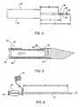
- introducer stylet 22includes a handle 28 and a stylet 30 having a distal end 32 and a proximal end 34 connected to handle 28.
- Handle 28may be made of a medical grade resin or other MRI compatible material.
- Stylet 30may also be made of an MRI compatible, medical grade material, such as 316 stainless steel or inconel 625.
- a distal end 32 of stylet 30includes a tissue piercing tip, such as a trocar tip, to facilitate penetration of stylet 30 into a patient's tissue.
- tissue piercing tipsuch as a trocar tip
- stylet 30may include other devices for of piercing the patient's tissue, including without limitation, devices that use a laser or radio frequencies (RF) to pierce the tissue.
- RFradio frequencies
- outer cannula 24extends from an open proximal end 36 to an open distal end 38, which is separated from proximal end 36 by a distance "B."
- outer cannula 24may be made from a medical grade resin or other MRI compatible material.
- proximal end 36may include a luer-style fitting or other suitable configuration for interfacing, but not necessarily connecting, outer cannula 24 with target confirmation device 26.
- a depth limiting member 39such as a rubber o-ring, may be moveably disposed on outer cannula 24 to limit the insertion depth of outer cannula 24 into the patient's body.
- outer cannula 24also includes an inner lumen 40 therethrough, which is open to communication with a fluid conduit 42 for supplying fluids, such as saline and anesthetics, or removing fluids, such as blood, from the patient's body.
- Fluid conduit 42communicates with inner lumen 40 via a port in outer cannula 24.
- outer cannula 24may include a haemostatic valve, depicted generally as element 41, or a manually operable valve 41' that can be selectively closed to prevent the escape of fluid from proximal end 36.
- Fluid conduit 42may also include a directional valve 43 to selectively control the supply and removal of fluid to and from inner lumen 40, respectively.
- target confirmation device 26is an elongated member that is sized to fit within inner lumen 40 of outer cannula 24.
- Target confirmation device 26which may be made of a medical grade resin or other MRI compatible material, extends from a connecting end 44 to a distal end 46.
- Connecting end 44may be configured with a cap 47 that abuts outer cannula 24.
- cap 47may include a luer-style fitting or other suitable feature for interfacing, but not necessarily connecting, target confirmation device 26 with outer cannula 24.
- Distal end 46 of target confirmation device 26is generally rounded to facilitate entry into the patient's body.
- a portion of target confirmation device 26is configured with a magnetic resonance imaging (MRI) identifiable material, such as inconel 625, titanium or other material with similar magnetic characteristics.
- MRImagnetic resonance imaging
- a targeting band 48is provided a distance "C" from connecting end 44, as shown in FIG. 3 ; the distance C being measured from the approximate center of targeting band 48 to connecting end 44 (or the inside of cap 47), for example.
- Targeting band 48provides a reference point in an MR image relative to the target biopsy tissue.
- the tip of target confirmation deviceitself may be used to provide the reference point in the MR image, provided the target confirmation device material exhibits a relatively low artifact during MR imaging.
- the term "artifact”describes a material's tendency to distort an MR image. A material exhibiting a relatively high artifact will render the body tissue surrounding the material unreadable in an MR image. Conversely, a material with a relatively low artifact will allow the material to be readily identified in the MR image and will not significantly distort the MR image of the surrounding tissue.
- the distal end 46 of target confirmation device 26may include a particular shape to help identify the location of target confirmation device 26 relative to the surrounding tissue.
- a portion of target confirmation device 26 adjacent the distal end 46has a smaller diameter relative to the remaining length.
- a portion of target confirmation device 26is tapered to provide an hour glass like image when viewed under MR. It will be appreciated that the embodiments represented in FIGS. 3A and 3B are not limited to the configurations shown, and that other configurations are with in the scope of the present invention.
- FIGS. 3C-3Dillustrate an embodiment of a localizing obturator 27 that may be used as a target confirmation device.
- Obturator 27includes an elongate body 29 defined by a distal end 31 and proximal end 33. Elongate body 29 is sized to so as to fit within inner lumen 40 of outer cannula 24.
- Distal end 31 of obturator 27may be generally rounded to facilitate entry into the patient's body.
- distal end 31is provided with one or more bores 35 formed in distal end 31.
- the intersection of bores 35may be at any angle, in one embodiment, cores 35 intersect one another at approximately 90°.
- generally lateral bore 35'is shown as extending completely through distal end 31 of obturator 27, it is also understood that one or end of bore 35' may be closed.
- generally axial bore 35"may open into a blind bore 35' where by both ends of bore 35' are closed.
- axial bore 35"has a predetermined length that extends a predetermined distance beyond generally lateral bore 35'.
- axial bore 35"extends through the length of elongate body 29, so as to form an elongated reservoir 37 that terminates at proximal end 33.
- FIG. 3Fonly a single bore 35" is formed at distal end 31.
- Single bore 35"extends the length of elongate body 29 to form an elongated reservoir 37 that terminates at proximal end 33.
- An intersecting bore(not shown) may also be provided adjacent to proximal end 33.
- Proximal end 33is sized so as to be larger than inner lumen 40 of cannula 24 such that the entire obturator 27 may not be delivered into a patient's body.
- proximal end 33includes a number of gripping depressions 45 to assist a user in gripping obturator 27.
- proximal end 33may include a cap, such as described above in connection with FIG. 3 .
- a contrast agentis introduced into the bores 35' 35" of obturator 27. In the embodiment shown in FIG. 3D , this may be accomplished by dipping distal end 31 into a contrast agent. Bores 35 permit the contrast agent to "wick" into the bores 35 and be held in the reservoir. Alternatively, contrast agent may be injected into bores 35', 35". Further, bores 35' and 35" may also be provided with plugs to seal contrast agent in reservoir 37.
- contrast agentAfter the contrast agent has been introduced into reservoir 37, when obturator 27 is placed into the body via outer cannula 24, the contrast agent is visible.
- Suitable contrast agentsinclude fluro-deoxyglucose (FDG), technicium 99 or other similar radioactive isotope. These radioactive isotopes are visible under imaging modalities such as PET (positron emission tomography), gamma cameras, or scintimammography.
- the radioactive isotopesattach to glucose, such that highly active cells (typically cancer) metabolize the glucose much more rapidly than normal tissue cells. Thus, the contrast agent is concentrated in the areas of high metabolic activities and shows up as bright areas under the imaging modalities.
- distal end 31passes through hemostatic valve 41. Because a portion of the contrast agent is retained within the reservoir 37, the contrast material will still be visible under the imaging modalities even if the frictional force between the hemostatic valve 41 and the distal end 31 of the obturator 27 wipes some of the contrast material off the obturator 27 outside surface. Further, in one embodiment, distal end 31 may be formed with an inwardly extending depression 49 that substantially surrounds bore 35.
- Depression 49further serves to reduce the likelihood that the contrast material will be removed from obturator 27.
- the visibility of the contrast agentis also significant as the contrast material that has wicked into the bores 35 view is pure contrast agent in that it has not been metabolized by in the surrounding tissue and thus has not be diluted. Once the obturator 27 has been placed in the body, the contrast agent will be easily visible under the imaging modalities, thereby indicating a target site where a biopsy instrument may be placed.
- introducer stylet 30may function as a target confirmation device.
- introducer stylet 30, and more particularly stylet 30,may be made of an MRI compatible material that preferably, but not necessarily, exhibits a relatively low artifact.
- FIG. 4An exemplary biopsy apparatus 50, which is suitable for use with medical system 20 of the present invention, is generally shown in FIG. 4 and in more detail in FIG. 5 .
- Apparatus 50includes a cutting element 52 sized for introduction into the patient's body and a hand piece 54.
- the exemplary biopsy apparatus 50is configured as a "tube-within-a-tube" cutting device. More particularly, cutting element 52 includes an outer cannula 56 having an outer lumen 57 and an inner cannula 58 sized to fit concentrically within the outer lumen.
- a motor or other motion generating deviceis provided within hand piece 54 to rotate and/or translate inner cannula 58 within outer cannula 56.
- Biopsy apparatus similar to apparatus 50can be seen by way of example in pending U.S. Patent Applications, Serial Nos. 09/707,022 and 09/864,03 , which are owned by the assignee of the present invention and are incorporated herein by reference in their entirely.
- outer cannula 56defines a tissue-receiving opening 60, which communicates with outer lumen 57.
- the working end of cutting element 52further includes a cutting board 64 that is disposed within outer lumen 57 at the distal end of outer cannula 56.
- Inner cannula 58defines an inner lumen 65 that is hollow along its entire length to provide for aspiration of the biopsy sample (tissue).
- Inner cannula 58terminates in a cutting edge 66 that may be formed by an inwardly beveled surface having a razor-sharp edge.
- an aspirating wand 68is shown that can be inserted into outer cannula 24.
- aspirating wand 68extends from a connecting end 70 to an insertion end 72 and includes an inner lumen 74 that extends from connecting end 70 to insertion end 72.
- Connecting end 70may include a luer interface or other suitable fitting for connecting aspirating wand 68 to a vacuum source (not shown).
- Aspirating wand 68may also include a cap 76 that can be placed onto connecting end 70 to inhibit fluid leakage when aspirating wand 68 is inserted into the patient.
- the haemostatic valve 41 in outer cannula 24seals against aspirating wand 68, as it does against target confirmation device 26 and biopsy device 50, when inserted into outer cannula 24. Additionally, the outside diameter of aspirating wand 68 is less than the inside diameter of inner lumen 40 to allow saline or other fluids introduced through fluid conduit 40 to pass into the patient's body. When cap 76 is removed and aspirating wand 68 is connected to a vacuum source, fluids, such as blood and saline, can be aspirated from the biopsy site.
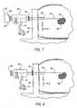
- system 20is employed to conduct a biopsy of a lesion within a patient's body.
- the target tissue or lesion to be biopsied and/or removed from the patient's body(denoted generally by mass 80 in FIG. 7 ) is located using a medical imaging system, such as MRI or other suitable imaging modality.
- a reference structure 82may be positioned adjacent the patient to assist in locating the target tissue. The location of the target tissue 80 relative to reference structure 82 may be determined along one or more axis.
- the target tissue location relative to reference structure 82is determined along the X and Y axes; however, the target tissue location may also be determined along all three of the X, Y and Z axes. While the described method employs a reference structure 82 to locate the target tissue, the reference structure is not necessarily required and a more "free-hand" approach may be utilized.
- reference structure 82includes a support grid having a number of holes therethrough. Each hole is sized to allow passage of outer cannula 24. The hole through which outer cannula 24 is ultimately inserted is determined by the location of target tissue 80 relative to reference structure 82 along the X and Y axes. The patient and reference structure 82 are viewed using a medical imaging system, such as MRI, to determine the location of the target tissue relative to reference structure 82.
- MRImagnetic resonance imaging system
- introducer stylet 22 and a portion of outer cannula 24are inserted through the support grid and into the patient's body, creating a pathway 84 to the target tissue 80 (see, e.g., FIG. 7 ).
- Introducer stylet 22is then removed from the patient's body leaving behind outer cannula 24 (see, e.g., FIG. 8 ).
- Fluidsmay be inserted into or removed from the patient's body through inner lumen 40 via fluid conduit 42. These fluids may include, for example, additional anesthetics and/or saline solution to cleanse pathway 84 and remove blood. Accumulated blood and other fluids within pathway 84 may be aspirated through fluid conduit 42 or by inserting aspirating wand 68 prior to insertion of target confirmation device 26.
- target confirmation device 26may be inserted into the patient's body through the port created by outer cannula 24 (see, e.g., FIGS. 8 and 9 ). With target confirmation device 26 properly inserted into outer cannula 24, an image of the target site is again taken to determine the location of targeting band 48 in relation to the target tissue and reference structure 82. If targeting band 48 is in the desired position adjacent target tissue 80 along the Z-axis, targeting device 26 is removed from outer cannula 24. However, if targeting band 48 is not in the desired position, then the position of target confirmation device 26 and outer cannula 24 is modified along the Z-axis until the desired position is achieved.
- depth limiting member 39is moved against reference structure 82 to inhibit movement of outer cannula 24 further into the patient.
- depth limiting membermay be moved directly against the patient's skin.
- Target confirmation device 26is then removed from outer cannula 24 and biopsy device 50 is inserted into outer cannula 24 until handpiece 54 abuts proximal end 36 of outer cannula 24.
- one or more samples of target tissue 80are removed from the patient through tissue-receiving opening 60.
- the correct position of tissue-receiving opening 60is ensured because the distance "C" between proximal end 44 of target confirmation device 26 and targeting band 48 (see, e.g., FIGS. 3 and 9 ), or the distance between proximal end 44 and the predetermined location on target confirmation device 26 ( FIGS. 3A and 3B ), is approximately equal to the distance between the center of tissue receiving opening 60 and handpiece 54 of biopsy device 50.
- the biopsy sitecan be aspirated using aspirating wand 68 (see, e.g., FIG. 11 ). During or after aspiration, a final image of the biopsy site can be taken to confirm removal of the target tissue. Finally, an identifiable marker, such as a collagen plug, or other medical treatment can be inserted into the biopsy site through outer cannula 24.
- the medical system of the present inventionlocalizes the target biopsy site in a manner that allows confirmation of the target biopsy site under MRI or other visualization modality, and allows positioning of a biopsy device to ensure the cutting element of the biopsy device can be accurately placed at the target biopsy site.
- the medical system of the present inventionalso facilitates the introduction and removal of fluids from the target site, including without limitation, anesthesia and blood, but minimizes the exposure of the fluids to the adjacent equipment and medical staff.
- the medical systemprovides access to the target site to introduce a medical treatment, such as a site marker, tamponade or other haemostatic agent, after removal of the tissue.
Landscapes
- Health & Medical Sciences (AREA)
- Life Sciences & Earth Sciences (AREA)
- Surgery (AREA)
- General Health & Medical Sciences (AREA)
- Veterinary Medicine (AREA)
- Heart & Thoracic Surgery (AREA)
- Medical Informatics (AREA)
- Molecular Biology (AREA)
- Engineering & Computer Science (AREA)
- Animal Behavior & Ethology (AREA)
- Pathology (AREA)
- Public Health (AREA)
- Biomedical Technology (AREA)
- Nuclear Medicine, Radiotherapy & Molecular Imaging (AREA)
- Oral & Maxillofacial Surgery (AREA)
- Magnetic Resonance Imaging Apparatus (AREA)
- Surgical Instruments (AREA)
- Nuclear Medicine (AREA)
- Fire-Extinguishing Compositions (AREA)
- Materials For Medical Uses (AREA)
- Lubricants (AREA)
- Infusion, Injection, And Reservoir Apparatuses (AREA)
Abstract
Description
- The present invention relates to the field of medical devices and more particularly to a medical system for introducing, among other things, minimally invasive surgical instruments and other medical treatments into a patient's body.
- Medical procedures have advanced to stages where less invasive or minimally invasive surgeries, diagnostic procedures and exploratory procedures have become desired and demanded by patients, physicians, and various medical industry administrators. To meet these demands, improved medical devices and instrumentation have been developed, such as cannulas or micro-cannulas, medical introducers, vacuum assisted biopsy apparatus, and other endoscopic related devices.
- In the field of tissue biopsy, minimally invasive biopsy devices have been developed that require only a single insertion point into a patient's body to remove one or more tissue samples. One such biopsy device incorporates a "tube-within-a-tube" design that includes an outer piercing needle having a sharpened distal end and a lateral opening that defines a tissue receiving port. An inner cutting member is slidingly received within the outer piercing needle, which serves to excise tissue that has prolapsed into the tissue receiving port. A vacuum is used to draw the excised tissue into the tissue receiving port and aspirates the excised tissue from the biopsy site once severed.
- Exemplary "tube-within-a-tube" biopsy devices are disclosed in pending
U.S. Patent Applications, Serial Nos. 09/707,022 and09/864,031 - While the exemplary MRI compatible biopsy devices have proven effective in operation, in some procedures it is desirable to create a pathway to the biopsy site for precise introduction of the biopsy device and other medical treatments into the patient. For these and other reasons, an MRI compatible medical introduction system is desirable for use with minimally invasive biopsy devices, such as those employing a "tube-within-a-tube" design.
- A medical target confirmation device, such as a localizing obturator, is disclosed. In one embodiment, the medical target confirmation device includes an elongate body member defined by a distal end and a proximal end. The distal end includes at least one bore extending therein. The bore receives contrast agent therein. A method for using the medical target confirmation device is also disclosed.
- Embodiments of the invention will now be described, by way of example, with reference to the accompanying drawings, wherein:
FIG. 1 is a side view of an introducer stylet according to an embodiment of the present invention;FIG. 2 is side view of an outer cannula and fluid conduit according to an embodiment of the present invention;FIG. 3 is a side view of a target confirmation device according to an embodiment of the present invention;FIGS. 3A and 3B are side views of a target confirmation device according to alternate embodiments of the present invention;FIG. 3C is a perspective view of a localizing obturator according to an embodiment of the present invention;FIG. 3D is a close-up view ofarea 3D, E, F of the localizing obturator ofFIG. 3C .FIG. 3E is a close-up view ofarea 3D, E, F of an alternative embodiment of the localizing obturator ofFIG. 3C .FIG. 3F is a close-up view of are 3D, E, F of yet another alternative embodiment of the localizing obturator ofFIG. 3C .FIG. 4 is a side view of an exemplary biopsy device for use with the introduction system of the present invention;FIG. 5 is a detailed cross-sectional view of a cutting element of the biopsy device ofFIG. 4 ;FIG. 6 is a side view of an aspiration wand suitable for insertion into the outer cannula; andFIGS. 7-11 are elevational views illustrating a medical procedure using the medical system of the present invention.- Referring now to the drawings, the preferred illustrative embodiments of the present invention are shown in detail. Although the drawings represent some preferred embodiments of the present invention, the drawings are not necessarily to scale and certain features may be exaggerated to better illustrate and explain the present invention. Further, the embodiments set forth herein are not intended to be exhaustive or otherwise limit or restrict the invention to the precise forms and configurations shown in the drawings and disclosed in the following detailed description.
- Referring to
FIGS. 1-3 , amedical system 20 is shown that includes anintroducer stylet 22, anouter cannula 24 and atarget confirmation device 26. As will be described in detail,system 20 is particularly, but not necessarily, suited for use in biopsy procedures that identify the target biopsy site using Magnetic Resonance Imaging (MRI) or comparable medical imaging modality. - In an embodiment, introducer
stylet 22 includes ahandle 28 and astylet 30 having adistal end 32 and aproximal end 34 connected to handle 28.Handle 28 may be made of a medical grade resin or other MRI compatible material.Stylet 30 may also be made of an MRI compatible, medical grade material, such as 316 stainless steel or inconel 625. - In a particular configuration, a
distal end 32 ofstylet 30 includes a tissue piercing tip, such as a trocar tip, to facilitate penetration ofstylet 30 into a patient's tissue. In addition to a trocar tip, it will be appreciated thatstylet 30 may include other devices for of piercing the patient's tissue, including without limitation, devices that use a laser or radio frequencies (RF) to pierce the tissue. The length ofstylet 30 is generally denoted by the reference character "A" inFIG. 1 . - Referring to the embodiment shown in
FIG. 2 ,outer cannula 24 extends from an openproximal end 36 to an opendistal end 38, which is separated fromproximal end 36 by a distance "B." Like introducerstylet 30,outer cannula 24 may be made from a medical grade resin or other MRI compatible material. In some configurations,proximal end 36 may include a luer-style fitting or other suitable configuration for interfacing, but not necessarily connecting,outer cannula 24 withtarget confirmation device 26. Adepth limiting member 39, such as a rubber o-ring, may be moveably disposed onouter cannula 24 to limit the insertion depth ofouter cannula 24 into the patient's body. - In an embodiment,
outer cannula 24 also includes aninner lumen 40 therethrough, which is open to communication with afluid conduit 42 for supplying fluids, such as saline and anesthetics, or removing fluids, such as blood, from the patient's body.Fluid conduit 42 communicates withinner lumen 40 via a port inouter cannula 24. In some configurations,outer cannula 24 may include a haemostatic valve, depicted generally aselement 41, or a manually operable valve 41' that can be selectively closed to prevent the escape of fluid fromproximal end 36.Fluid conduit 42 may also include adirectional valve 43 to selectively control the supply and removal of fluid to and frominner lumen 40, respectively. - In the embodiment shown in
FIG. 3 ,target confirmation device 26 is an elongated member that is sized to fit withininner lumen 40 ofouter cannula 24.Target confirmation device 26, which may be made of a medical grade resin or other MRI compatible material, extends from a connectingend 44 to adistal end 46. Connectingend 44 may be configured with acap 47 that abutsouter cannula 24. In some configurations,cap 47 may include a luer-style fitting or other suitable feature for interfacing, but not necessarily connecting,target confirmation device 26 withouter cannula 24. Distal end 46 oftarget confirmation device 26 is generally rounded to facilitate entry into the patient's body. In an embodiment, a portion oftarget confirmation device 26 is configured with a magnetic resonance imaging (MRI) identifiable material, such as inconel 625, titanium or other material with similar magnetic characteristics. In one particular configuration, a targetingband 48 is provided a distance "C" from connectingend 44, as shown inFIG. 3 ; the distance C being measured from the approximate center of targetingband 48 to connecting end 44 (or the inside of cap 47), for example. Targetingband 48 provides a reference point in an MR image relative to the target biopsy tissue.- In another embodiment of the present invention, the tip of target confirmation device itself may be used to provide the reference point in the MR image, provided the target confirmation device material exhibits a relatively low artifact during MR imaging. As used herein, the term "artifact" describes a material's tendency to distort an MR image. A material exhibiting a relatively high artifact will render the body tissue surrounding the material unreadable in an MR image. Conversely, a material with a relatively low artifact will allow the material to be readily identified in the MR image and will not significantly distort the MR image of the surrounding tissue.
- As shown in the embodiments of
FIGS. 3A and 3B , thedistal end 46 oftarget confirmation device 26 may include a particular shape to help identify the location oftarget confirmation device 26 relative to the surrounding tissue. In the embodiment ofFIG. 3A , a portion oftarget confirmation device 26 adjacent thedistal end 46 has a smaller diameter relative to the remaining length. In the embodiment ofFIG. 3B , a portion oftarget confirmation device 26 is tapered to provide an hour glass like image when viewed under MR. It will be appreciated that the embodiments represented inFIGS. 3A and 3B are not limited to the configurations shown, and that other configurations are with in the scope of the present invention. FIGS. 3C-3D illustrate an embodiment of a localizingobturator 27 that may be used as a target confirmation device.Obturator 27 includes anelongate body 29 defined by adistal end 31 andproximal end 33.Elongate body 29 is sized to so as to fit withininner lumen 40 ofouter cannula 24.Distal end 31 ofobturator 27 may be generally rounded to facilitate entry into the patient's body. In the embodiment shown inFIGS. 3C and 3D ,distal end 31 is provided with one ormore bores 35 formed indistal end 31. In one embodiment, there are at least two such bores, a generally lateral bore 35' and a generallyaxial bore 35", which intersect one another to form aninternal reservoir 37, to be explained further below. While the intersection ofbores 35 may be at any angle, in one embodiment,cores 35 intersect one another at approximately 90°. While generally lateral bore 35' is shown as extending completely throughdistal end 31 ofobturator 27, it is also understood that one or end of bore 35' may be closed. In yet another alternative embodiment, generallyaxial bore 35" may open into a blind bore 35' where by both ends of bore 35' are closed.- In the embodiment shown in
FIG. 3D ,axial bore 35" has a predetermined length that extends a predetermined distance beyond generally lateral bore 35'. In another alternative embodiment, as shown inFIG. 3E ,axial bore 35" extends through the length ofelongate body 29, so as to form anelongated reservoir 37 that terminates atproximal end 33. In yet another alternative embodiment, as shown inFIG. 3F , only asingle bore 35" is formed atdistal end 31. Single bore 35" extends the length ofelongate body 29 to form anelongated reservoir 37 that terminates atproximal end 33. An intersecting bore (not shown) may also be provided adjacent toproximal end 33. Proximal end 33 is sized so as to be larger thaninner lumen 40 ofcannula 24 such that theentire obturator 27 may not be delivered into a patient's body. In one embodiment,proximal end 33 includes a number ofgripping depressions 45 to assist a user in grippingobturator 27. Alternatively,proximal end 33 may include a cap, such as described above in connection withFIG. 3 .- To assist in imaging a target site, a contrast agent is introduced into the bores 35' 35" of
obturator 27. In the embodiment shown inFIG. 3D , this may be accomplished by dippingdistal end 31 into a contrast agent.Bores 35 permit the contrast agent to "wick" into thebores 35 and be held in the reservoir. Alternatively, contrast agent may be injected intobores 35', 35". Further, bores 35' and 35" may also be provided with plugs to seal contrast agent inreservoir 37. - After the contrast agent has been introduced into
reservoir 37, whenobturator 27 is placed into the body viaouter cannula 24, the contrast agent is visible. Suitable contrast agents include fluro-deoxyglucose (FDG), technicium 99 or other similar radioactive isotope. These radioactive isotopes are visible under imaging modalities such as PET (positron emission tomography), gamma cameras, or scintimammography. The radioactive isotopes attach to glucose, such that highly active cells (typically cancer) metabolize the glucose much more rapidly than normal tissue cells. Thus, the contrast agent is concentrated in the areas of high metabolic activities and shows up as bright areas under the imaging modalities. - In operation, after the contrast agent is introduced into the reservoir, either by dipping or by injection, at least a portion of the contrast agent is retained within the
reservoir 37. Next,obturator 27 is inserted intoinner lumen 40 ofouter cannula 24. Asobtuator 27 is inserted therein,distal end 31 passes throughhemostatic valve 41. Because a portion of the contrast agent is retained within thereservoir 37, the contrast material will still be visible under the imaging modalities even if the frictional force between thehemostatic valve 41 and thedistal end 31 of theobturator 27 wipes some of the contrast material off theobturator 27 outside surface. Further, in one embodiment,distal end 31 may be formed with an inwardly extendingdepression 49 that substantially surroundsbore 35.Depression 49 further serves to reduce the likelihood that the contrast material will be removed fromobturator 27. The visibility of the contrast agent is also significant as the contrast material that has wicked into thebores 35 view is pure contrast agent in that it has not been metabolized by in the surrounding tissue and thus has not be diluted. Once theobturator 27 has been placed in the body, the contrast agent will be easily visible under the imaging modalities, thereby indicating a target site where a biopsy instrument may be placed. - In still another embodiment,
introducer stylet 30 may function as a target confirmation device. In this embodiment,introducer stylet 30, and more particularlystylet 30, may be made of an MRI compatible material that preferably, but not necessarily, exhibits a relatively low artifact. - An
exemplary biopsy apparatus 50, which is suitable for use withmedical system 20 of the present invention, is generally shown inFIG. 4 and in more detail inFIG. 5 . Apparatus 50 includes a cuttingelement 52 sized for introduction into the patient's body and ahand piece 54. Theexemplary biopsy apparatus 50 is configured as a "tube-within-a-tube" cutting device. More particularly, cuttingelement 52 includes anouter cannula 56 having anouter lumen 57 and aninner cannula 58 sized to fit concentrically within the outer lumen. A motor or other motion generating device is provided withinhand piece 54 to rotate and/or translateinner cannula 58 withinouter cannula 56. Biopsy apparatus similar toapparatus 50 can be seen by way of example in pendingU.S. Patent Applications, Serial Nos. 09/707,022 and09/864,03 , which are owned by the assignee of the present invention and are incorporated herein by reference in their entirely.- A particular embodiment of the working end of cutting
element 52 is depicted inFIG. 5 . In the illustrated embodiment,outer cannula 56 defines a tissue-receivingopening 60, which communicates withouter lumen 57. The working end of cuttingelement 52 further includes a cuttingboard 64 that is disposed withinouter lumen 57 at the distal end ofouter cannula 56.Inner cannula 58 defines aninner lumen 65 that is hollow along its entire length to provide for aspiration of the biopsy sample (tissue).Inner cannula 58 terminates in acutting edge 66 that may be formed by an inwardly beveled surface having a razor-sharp edge. - Referring to
FIG. 6 , an aspiratingwand 68 is shown that can be inserted intoouter cannula 24. In an embodiment, aspiratingwand 68 extends from a connectingend 70 to aninsertion end 72 and includes an inner lumen 74 that extends from connectingend 70 toinsertion end 72. Connectingend 70 may include a luer interface or other suitable fitting for connecting aspiratingwand 68 to a vacuum source (not shown). Aspiratingwand 68 may also include acap 76 that can be placed onto connectingend 70 to inhibit fluid leakage when aspiratingwand 68 is inserted into the patient. Thehaemostatic valve 41 inouter cannula 24 seals against aspiratingwand 68, as it does againsttarget confirmation device 26 andbiopsy device 50, when inserted intoouter cannula 24. Additionally, the outside diameter of aspiratingwand 68 is less than the inside diameter ofinner lumen 40 to allow saline or other fluids introduced throughfluid conduit 40 to pass into the patient's body. Whencap 76 is removed and aspiratingwand 68 is connected to a vacuum source, fluids, such as blood and saline, can be aspirated from the biopsy site. - Referring to
FIGS. 7-11 , a medicalprocedure using system 20 of the present invention will be described. In an embodiment,system 20 is employed to conduct a biopsy of a lesion within a patient's body. The target tissue or lesion to be biopsied and/or removed from the patient's body (denoted generally bymass 80 inFIG. 7 ) is located using a medical imaging system, such as MRI or other suitable imaging modality. Areference structure 82 may be positioned adjacent the patient to assist in locating the target tissue. The location of thetarget tissue 80 relative to referencestructure 82 may be determined along one or more axis. In the illustrated embodiment, the target tissue location relative to referencestructure 82 is determined along the X and Y axes; however, the target tissue location may also be determined along all three of the X, Y and Z axes. While the described method employs areference structure 82 to locate the target tissue, the reference structure is not necessarily required and a more "free-hand" approach may be utilized. - In an embodiment,
reference structure 82 includes a support grid having a number of holes therethrough. Each hole is sized to allow passage ofouter cannula 24. The hole through whichouter cannula 24 is ultimately inserted is determined by the location oftarget tissue 80 relative to referencestructure 82 along the X and Y axes. The patient andreference structure 82 are viewed using a medical imaging system, such as MRI, to determine the location of the target tissue relative to referencestructure 82. - After application of anesthesia, the stylet portion of
introducer stylet 22 and a portion ofouter cannula 24 are inserted through the support grid and into the patient's body, creating apathway 84 to the target tissue 80 (see, e.g.,FIG. 7 ).Introducer stylet 22 is then removed from the patient's body leaving behind outer cannula 24 (see, e.g.,FIG. 8 ). - Fluids may be inserted into or removed from the patient's body through
inner lumen 40 viafluid conduit 42. These fluids may include, for example, additional anesthetics and/or saline solution to cleansepathway 84 and remove blood. Accumulated blood and other fluids withinpathway 84 may be aspirated throughfluid conduit 42 or by inserting aspiratingwand 68 prior to insertion oftarget confirmation device 26. - Once
introducer stylet 22 is removed fromouter cannula 24,target confirmation device 26 may be inserted into the patient's body through the port created by outer cannula 24 (see, e.g.,FIGS. 8 and9 ). Withtarget confirmation device 26 properly inserted intoouter cannula 24, an image of the target site is again taken to determine the location of targetingband 48 in relation to the target tissue andreference structure 82. If targetingband 48 is in the desired positionadjacent target tissue 80 along the Z-axis, targetingdevice 26 is removed fromouter cannula 24. However, if targetingband 48 is not in the desired position, then the position oftarget confirmation device 26 andouter cannula 24 is modified along the Z-axis until the desired position is achieved. - Once the desired position is achieved,
depth limiting member 39 is moved againstreference structure 82 to inhibit movement ofouter cannula 24 further into the patient. When noreference structure 82 is used, depth limiting member may be moved directly against the patient's skin.Target confirmation device 26 is then removed fromouter cannula 24 andbiopsy device 50 is inserted intoouter cannula 24 untilhandpiece 54 abutsproximal end 36 ofouter cannula 24. In the embodiment illustrated inFIG. 10 , one or more samples oftarget tissue 80 are removed from the patient through tissue-receivingopening 60. The correct position of tissue-receivingopening 60 is ensured because the distance "C" betweenproximal end 44 oftarget confirmation device 26 and targeting band 48 (see, e.g.,FIGS. 3 and9 ), or the distance betweenproximal end 44 and the predetermined location on target confirmation device 26 (FIGS. 3A and 3B ), is approximately equal to the distance between the center oftissue receiving opening 60 andhandpiece 54 ofbiopsy device 50. - After completion of the biopsy, the biopsy site can be aspirated using aspirating wand 68 (see, e.g.,
FIG. 11 ). During or after aspiration, a final image of the biopsy site can be taken to confirm removal of the target tissue. Finally, an identifiable marker, such as a collagen plug, or other medical treatment can be inserted into the biopsy site throughouter cannula 24. - Among other features, the medical system of the present invention localizes the target biopsy site in a manner that allows confirmation of the target biopsy site under MRI or other visualization modality, and allows positioning of a biopsy device to ensure the cutting element of the biopsy device can be accurately placed at the target biopsy site. The medical system of the present invention also facilitates the introduction and removal of fluids from the target site, including without limitation, anesthesia and blood, but minimizes the exposure of the fluids to the adjacent equipment and medical staff. In addition to allowing the medical staff to identify the presence of significant bleeding and to introduce a biopsy device into the patient, the medical system provides access to the target site to introduce a medical treatment, such as a site marker, tamponade or other haemostatic agent, after removal of the tissue.
- The present invention has been particularly shown and described with reference to the foregoing embodiments, which are merely illustrative of the best modes for carrying out the invention. It should be understood by those skilled in the art that various alternatives to the embodiments of the invention described herein may be employed in practicing the invention without departing from the scope of the invention as defined in the following claims. It is intended that the following claims define the scope of the invention and that the method and apparatus within the scope of these claims and their equivalents be covered thereby. This description of the invention should be understood to include all novel and non-obvious combinations of elements described herein, and claims may be presented in this or a later application to any novel and non-obvious combination of these elements. Moreover, the foregoing embodiments are illustrative, and no single feature or element is essential to all possible combinations that may be claimed in this or a later application.
Claims (18)
- A medical targeting device (27) for a target confirmation procedure, comprising:an elongate body member (29) defined by a distal end (31) and a proximal end (33);wherein said distal end (31) includes at least one bore (35, 35', 35") extending therein;characterised in that the bore contains a fluid contrast agent which is received in the bore (35, 35', 35") by one of wicking or injecting.
- The medical targeting device (27) of claim 1, wherein said distal end (31) includes two bores (35', 35") formed therein.
- The medical targeting device (27) of claim 2, wherein the bores (35', 35") intersect one another.
- The medical targeting device (27) of claim 3, wherein the bores (35', 35") intersect one another at an approximately 90° angle.
- The medical targeting device (27) of claim 4, wherein the bores (35', 35") form a cross-shaped passage.
- The medical targeting device (27) of claim 4, wherein said bores (35', 35") form a t-shaped passage.
- The medical targeting device (27) of claim 1, wherein one bore (35") extends substantially the length of said body (29).
- The medical targeting device (27) of claim 7, further including a plug to selectively seal said bore (35, 35', 35 "), closed so as to seal said contrast agent in said medical targeting device.
- The medical targeting device (27) of claim 1, wherein said proximal end (33) includes a gripping portion (45).
- The medical targeting device (27) of claim 1, further including an inwardly extending depression (49) formed at said distal end (31), wherein said depression (49) at least partially surrounds said bore (35, 35").
- The medical target device (27) of claim 1, wherein said contrast agent is a radioactive isotope.
- The medical targeting device (27) of claim 11, wherein said contrast agent is fluro-deoxygluscose.
- The medical targeting device (27) of claim 11, wherein the contrast agent is technetium 99.
- The medical targeting device (27) of claim 3, wherein said intersecting bores include a generally laterally disposed bore and a generally axial disposed bore.
- The medical targeting device (27) of claim 14, wherein said generally laterally disposed bore has at least one closed end.
- The medical targeting device (27) of claim 14, wherein said generally axial disposed bore extends substantially the length of said body.
- The medical targeting device (27) of claim 16, wherein said generally laterally disposed bore is positioned adjacent said proximal end.
- A method of preparing a medical targeting device (27) for use in a target confirmation procedure, the medical targeting device (27) comprising a localizing obturator that has at least one bore (35, 35', 35") formed in a distal end thereof; the method beingcharacterised by introducing a contrast agent into said bore (35, 35', 35") such that a portion of said contrast agent is retained within a reservoir formed by said bore (35, 35', 35"); wherein said introducing step is accomplished either by dipping the distal end of said localizing obturator into said contrast agent such that contrast agent is wicked into said bore (35, 35', 35"), or by injecting contrast agent into said bore.
Applications Claiming Priority (1)
| Application Number | Priority Date | Filing Date | Title |
|---|---|---|---|
| US11/516,277US20070260267A1 (en) | 2002-10-07 | 2006-09-06 | Localizing obturator |
Publications (2)
| Publication Number | Publication Date |
|---|---|
| EP1897507A1 EP1897507A1 (en) | 2008-03-12 |
| EP1897507B1true EP1897507B1 (en) | 2010-07-28 |
Family
ID=38537857
Family Applications (1)
| Application Number | Title | Priority Date | Filing Date |
|---|---|---|---|
| EP07251843AActiveEP1897507B1 (en) | 2006-09-06 | 2007-05-02 | Localizing obturator |
Country Status (7)
| Country | Link |
|---|---|
| US (1) | US20070260267A1 (en) |
| EP (1) | EP1897507B1 (en) |
| JP (1) | JP2008068065A (en) |
| AT (1) | ATE475366T1 (en) |
| CA (1) | CA2589709A1 (en) |
| DE (1) | DE602007008019D1 (en) |
| MX (1) | MX2007010831A (en) |
Families Citing this family (10)
| Publication number | Priority date | Publication date | Assignee | Title |
|---|---|---|---|---|
| US20080161720A1 (en)* | 2002-10-07 | 2008-07-03 | Nicoson Zachary R | Registration system |
| US20090163870A1 (en)* | 2007-12-20 | 2009-06-25 | Jake Flagle | Targeting obturator |
| AU2009201610A1 (en)* | 2008-04-23 | 2009-11-19 | Devicor Medical Products, Inc. | PEM and BSGI biopsy devices and methods |
| US8532748B2 (en)* | 2008-04-23 | 2013-09-10 | Devicor Medical Products, Inc. | Devices useful in imaging |
| US20090270726A1 (en)* | 2008-04-23 | 2009-10-29 | Leimbach Jessica P | Methods For Imaging |
| US8864681B2 (en)* | 2008-04-23 | 2014-10-21 | Devicor Medical Products, Inc. | Biopsy devices |
| US8206315B2 (en)* | 2008-09-30 | 2012-06-26 | Suros Surgical Systems, Inc. | Real-time pathology |
| US20100280409A1 (en)* | 2008-09-30 | 2010-11-04 | Mark Joseph L | Real-time pathology |
| US8554309B2 (en)* | 2010-09-23 | 2013-10-08 | Hologic, Inc. | Localizing obturator with site marking capability |
| DE102013112471A1 (en)* | 2013-11-13 | 2015-05-13 | Agron Lumiani | Biopsy needle system for MR guided biopsy |
Family Cites Families (53)
| Publication number | Priority date | Publication date | Assignee | Title |
|---|---|---|---|---|
| SE390886B (en)* | 1975-06-23 | 1977-01-31 | Siemens Elema Ab | CATHETER FOR SELECTIVE CORONAR ARTERIOGRAPHY OF LEFT CORONAR SPECIES |
| US4177814A (en)* | 1978-01-18 | 1979-12-11 | KLI, Incorporated | Self-sealing cannula |
| US4212392A (en)* | 1979-02-09 | 1980-07-15 | Bristol-Myers Company | Medical emergency treatment kit |
| JPS58142016U (en)* | 1982-03-17 | 1983-09-24 | 株式会社トツプ | biopsy needle |
| US4781198A (en)* | 1986-09-08 | 1988-11-01 | Kanabrocki Eugene L | Biopsy tracer needle |
| US5316013A (en)* | 1991-08-26 | 1994-05-31 | Hart Enterprises, Inc. | Oriented biopsy needle assembly |
| US5281197A (en)* | 1992-07-27 | 1994-01-25 | Symbiosis Corporation | Endoscopic hemostatic agent delivery system |
| US5649547A (en)* | 1994-03-24 | 1997-07-22 | Biopsys Medical, Inc. | Methods and devices for automated biopsy and collection of soft tissue |
| US5647347A (en)* | 1994-10-21 | 1997-07-15 | Glaxo Wellcome Inc. | Medicament carrier for dry powder inhalator |
| US5647374A (en)* | 1994-12-30 | 1997-07-15 | North American Scientific | Needle for imaging and sampling |
| US5766134A (en)* | 1995-07-18 | 1998-06-16 | Atrion Medical Products, Inc. | Autogenous bone specimen collector |
| US5782764A (en)* | 1995-11-07 | 1998-07-21 | Iti Medical Technologies, Inc. | Fiber composite invasive medical instruments and methods for use in interventional imaging procedures |
| US6276661B1 (en)* | 1996-11-06 | 2001-08-21 | Medtronic, Inc. | Pressure actuated introducer valve |
| US5938604A (en)* | 1997-05-28 | 1999-08-17 | Capintec, Inc. | Radioactive needle for biopsy localization and a method for making the radioactive needle |
| US6251418B1 (en)* | 1997-12-18 | 2001-06-26 | C.R. Bard, Inc. | Systems and methods for local delivery of an agent |
| US6213988B1 (en)* | 1998-02-10 | 2001-04-10 | Medtronic, Inc. | Introducer with external hemostasis clip |
| US6758848B2 (en)* | 1998-03-03 | 2004-07-06 | Senorx, Inc. | Apparatus and method for accessing a body site |
| JPH11267133A (en)* | 1998-03-25 | 1999-10-05 | Olympus Optical Co Ltd | Therapeutic apparatus |
| US6161034A (en)* | 1999-02-02 | 2000-12-12 | Senorx, Inc. | Methods and chemical preparations for time-limited marking of biopsy sites |
| US6347241B2 (en)* | 1999-02-02 | 2002-02-12 | Senorx, Inc. | Ultrasonic and x-ray detectable biopsy site marker and apparatus for applying it |
| US6425871B1 (en)* | 1998-05-13 | 2002-07-30 | Tomo-Vision Gmbh | Puncturing device for tomography |
| US6440147B1 (en)* | 1998-09-03 | 2002-08-27 | Rubicor Medical, Inc. | Excisional biopsy devices and methods |
| US6280399B1 (en)* | 1998-10-06 | 2001-08-28 | Allegiance Corporation | Substance delivery device for use with a procedure performing instrument |
| US20010047183A1 (en)* | 2000-04-05 | 2001-11-29 | Salvatore Privitera | Surgical device for the collection of soft tissue |
| US6371904B1 (en)* | 1998-12-24 | 2002-04-16 | Vivant Medical, Inc. | Subcutaneous cavity marking device and method |
| US7651505B2 (en)* | 2002-06-17 | 2010-01-26 | Senorx, Inc. | Plugged tip delivery for marker placement |
| US6725083B1 (en)* | 1999-02-02 | 2004-04-20 | Senorx, Inc. | Tissue site markers for in VIVO imaging |
| US6272372B1 (en)* | 1999-06-09 | 2001-08-07 | Biopsy Sciences, Llc | Needle having inflatable position indicator |
| US6505210B1 (en)* | 1999-06-14 | 2003-01-07 | International Business Machines Corporation | Federation of naming contexts across multiple and/or diverse underlying directory technologies |
| US6575991B1 (en)* | 1999-06-17 | 2003-06-10 | Inrad, Inc. | Apparatus for the percutaneous marking of a lesion |
| JP2001137248A (en)* | 1999-11-16 | 2001-05-22 | Olympus Optical Co Ltd | Sampler |
| US6551283B1 (en)* | 2000-01-25 | 2003-04-22 | St. Jude Medical, Daig Division | Hemostasis valve |
| JP2001252261A (en)* | 2000-02-29 | 2001-09-18 | Ge Medical Systems Global Technology Co Llc | Immersion piece and magnetic resonance imaging instrument |
| US6628982B1 (en)* | 2000-03-30 | 2003-09-30 | The Regents Of The University Of Michigan | Internal marker device for identification of biological substances |
| US20010035413A1 (en)* | 2000-05-01 | 2001-11-01 | Douglas Thai | Non-spill container |
| US6494844B1 (en)* | 2000-06-21 | 2002-12-17 | Sanarus Medical, Inc. | Device for biopsy and treatment of breast tumors |
| US6758824B1 (en)* | 2000-11-06 | 2004-07-06 | Suros Surgical Systems, Inc. | Biopsy apparatus |
| US6626849B2 (en)* | 2001-11-01 | 2003-09-30 | Ethicon Endo-Surgery, Inc. | MRI compatible surgical biopsy device |
| US7192404B2 (en)* | 2001-12-12 | 2007-03-20 | Ethicon Endo-Surgery, Inc. | MRI compatible surgical biopsy device having a tip which leaves an artifact |
| US6824516B2 (en)* | 2002-03-11 | 2004-11-30 | Medsci Technologies, Inc. | System for examining, mapping, diagnosing, and treating diseases of the prostate |
| US7769426B2 (en)* | 2002-04-23 | 2010-08-03 | Ethicon Endo-Surgery, Inc. | Method for using an MRI compatible biopsy device with detachable probe |
| US7826883B2 (en)* | 2002-04-23 | 2010-11-02 | Devicor Medical Products, Inc. | Localization mechanism for an MRI compatible biopsy device |
| US20030199753A1 (en)* | 2002-04-23 | 2003-10-23 | Ethicon Endo-Surgery | MRI compatible biopsy device with detachable probe |
| US7347829B2 (en)* | 2002-10-07 | 2008-03-25 | Suros Surgical Systems, Inc. | Introduction system for minimally invasive surgical instruments |
| US7438692B2 (en)* | 2002-10-18 | 2008-10-21 | Mark Tsonton | Localization mechanism for an MRI compatible biopsy device |
| US7792568B2 (en)* | 2003-03-17 | 2010-09-07 | Boston Scientific Scimed, Inc. | MRI-visible medical devices |
| DE10337368A1 (en)* | 2003-08-08 | 2005-03-03 | Technische Universität Dresden | Diagnosis of pancreatic cancer by detecting expression of the a disintegrin and metalloprotease domain 9 (ADAM9) protein using specific antibodies, also therapeutic use of these antibodies and of ADAM9-specific nucleic acids |
| CA2537602A1 (en)* | 2003-09-05 | 2005-03-17 | D-Wave Systems, Inc. | Superconducting phase-charge qubits |
| US7445739B2 (en)* | 2004-03-24 | 2008-11-04 | Ethicon Endo-Surgery, Inc. | Method of forming a biopsy device |
| US9345456B2 (en)* | 2004-03-24 | 2016-05-24 | Devicor Medical Products, Inc. | Biopsy device |
| US7708751B2 (en)* | 2004-05-21 | 2010-05-04 | Ethicon Endo-Surgery, Inc. | MRI biopsy device |
| ATE444712T1 (en)* | 2004-05-21 | 2009-10-15 | Ethicon Endo Surgery Inc | MRI BIOPSY DEVICE WITH A DISPLAYABLE PENETRATION PART |
| GB0422004D0 (en)* | 2004-10-05 | 2004-11-03 | Amersham Plc | Method of deprotection |
- 2006
- 2006-09-06USUS11/516,277patent/US20070260267A1/ennot_activeAbandoned
- 2007
- 2007-05-02EPEP07251843Apatent/EP1897507B1/enactiveActive
- 2007-05-02ATAT07251843Tpatent/ATE475366T1/ennot_activeIP Right Cessation
- 2007-05-02DEDE602007008019Tpatent/DE602007008019D1/enactiveActive
- 2007-05-23CACA002589709Apatent/CA2589709A1/ennot_activeAbandoned
- 2007-06-27JPJP2007168351Apatent/JP2008068065A/enactivePending
- 2007-09-05MXMX2007010831Apatent/MX2007010831A/enactiveIP Right Grant
Also Published As
| Publication number | Publication date |
|---|---|
| US20070260267A1 (en) | 2007-11-08 |
| ATE475366T1 (en) | 2010-08-15 |
| JP2008068065A (en) | 2008-03-27 |
| DE602007008019D1 (en) | 2010-09-09 |
| CA2589709A1 (en) | 2008-03-06 |
| EP1897507A1 (en) | 2008-03-12 |
| MX2007010831A (en) | 2009-02-10 |
Similar Documents
| Publication | Publication Date | Title |
|---|---|---|
| EP1551308B1 (en) | Introduction system for minimally invasive surgical instruments | |
| EP1897507B1 (en) | Localizing obturator | |
| US8554309B2 (en) | Localizing obturator with site marking capability | |
| US20080200834A1 (en) | Introducer device for improved imaging | |
| US20120078087A1 (en) | Tissue Localization Device and Method | |
| CA2512490C (en) | Self-contained, self-piercing, side-expelling marking apparatus | |
| JP2008068065A5 (en) | ||
| EP3713499B1 (en) | Adjustable targeting set for mri guided biopsy procedure | |
| US20120157967A1 (en) | System and method for minimally invasive disease therapy | |
| US20120095365A1 (en) | Adjustable spacer | |
| JP2000070273A (en) | Biopsy device for surgery | |
| US20100114031A1 (en) | Introducer localization assemblies | |
| US20090163870A1 (en) | Targeting obturator | |
| EP2113204A2 (en) | PEM and BSGI biopsy devices and methods | |
| JP6719450B2 (en) | Medical device | |
| US20190029758A1 (en) | Mri targeting set with improved targeting sleeve |
Legal Events
| Date | Code | Title | Description |
|---|---|---|---|
| PUAI | Public reference made under article 153(3) epc to a published international application that has entered the european phase | Free format text:ORIGINAL CODE: 0009012 | |
| AK | Designated contracting states | Kind code of ref document:A1 Designated state(s):AT BE BG CH CY CZ DE DK EE ES FI FR GB GR HU IE IS IT LI LT LU LV MC MT NL PL PT RO SE SI SK TR | |
| AX | Request for extension of the european patent | Extension state:AL BA HR MK YU | |
| 17P | Request for examination filed | Effective date:20080908 | |
| 17Q | First examination report despatched | Effective date:20081013 | |
| AKX | Designation fees paid | Designated state(s):AT BE BG CH CY CZ DE DK EE ES FI FR GB GR HU IE IS IT LI LT LU LV MC MT NL PL PT RO SE SI SK TR | |
| GRAP | Despatch of communication of intention to grant a patent | Free format text:ORIGINAL CODE: EPIDOSNIGR1 | |
| GRAS | Grant fee paid | Free format text:ORIGINAL CODE: EPIDOSNIGR3 | |
| GRAA | (expected) grant | Free format text:ORIGINAL CODE: 0009210 | |
| AK | Designated contracting states | Kind code of ref document:B1 Designated state(s):AT BE BG CH CY CZ DE DK EE ES FI FR GB GR HU IE IS IT LI LT LU LV MC MT NL PL PT RO SE SI SK TR | |
| REG | Reference to a national code | Ref country code:GB Ref legal event code:FG4D | |
| REG | Reference to a national code | Ref country code:CH Ref legal event code:EP | |
| REG | Reference to a national code | Ref country code:IE Ref legal event code:FG4D | |
| REF | Corresponds to: | Ref document number:602007008019 Country of ref document:DE Date of ref document:20100909 Kind code of ref document:P | |
| REG | Reference to a national code | Ref country code:NL Ref legal event code:VDEP Effective date:20100728 | |
| LTIE | Lt: invalidation of european patent or patent extension | Effective date:20100728 | |
| PG25 | Lapsed in a contracting state [announced via postgrant information from national office to epo] | Ref country code:LT Free format text:LAPSE BECAUSE OF FAILURE TO SUBMIT A TRANSLATION OF THE DESCRIPTION OR TO PAY THE FEE WITHIN THE PRESCRIBED TIME-LIMIT Effective date:20100728 Ref country code:FI Free format text:LAPSE BECAUSE OF FAILURE TO SUBMIT A TRANSLATION OF THE DESCRIPTION OR TO PAY THE FEE WITHIN THE PRESCRIBED TIME-LIMIT Effective date:20100728 Ref country code:AT Free format text:LAPSE BECAUSE OF FAILURE TO SUBMIT A TRANSLATION OF THE DESCRIPTION OR TO PAY THE FEE WITHIN THE PRESCRIBED TIME-LIMIT Effective date:20100728 Ref country code:NL Free format text:LAPSE BECAUSE OF FAILURE TO SUBMIT A TRANSLATION OF THE DESCRIPTION OR TO PAY THE FEE WITHIN THE PRESCRIBED TIME-LIMIT Effective date:20100728 | |
| PG25 | Lapsed in a contracting state [announced via postgrant information from national office to epo] | Ref country code:SI Free format text:LAPSE BECAUSE OF FAILURE TO SUBMIT A TRANSLATION OF THE DESCRIPTION OR TO PAY THE FEE WITHIN THE PRESCRIBED TIME-LIMIT Effective date:20100728 Ref country code:PT Free format text:LAPSE BECAUSE OF FAILURE TO SUBMIT A TRANSLATION OF THE DESCRIPTION OR TO PAY THE FEE WITHIN THE PRESCRIBED TIME-LIMIT Effective date:20101129 Ref country code:PL Free format text:LAPSE BECAUSE OF FAILURE TO SUBMIT A TRANSLATION OF THE DESCRIPTION OR TO PAY THE FEE WITHIN THE PRESCRIBED TIME-LIMIT Effective date:20100728 Ref country code:IS Free format text:LAPSE BECAUSE OF FAILURE TO SUBMIT A TRANSLATION OF THE DESCRIPTION OR TO PAY THE FEE WITHIN THE PRESCRIBED TIME-LIMIT Effective date:20101128 Ref country code:CY Free format text:LAPSE BECAUSE OF FAILURE TO SUBMIT A TRANSLATION OF THE DESCRIPTION OR TO PAY THE FEE WITHIN THE PRESCRIBED TIME-LIMIT Effective date:20100728 Ref country code:BG Free format text:LAPSE BECAUSE OF FAILURE TO SUBMIT A TRANSLATION OF THE DESCRIPTION OR TO PAY THE FEE WITHIN THE PRESCRIBED TIME-LIMIT Effective date:20101028 | |
| PG25 | Lapsed in a contracting state [announced via postgrant information from national office to epo] | Ref country code:SE Free format text:LAPSE BECAUSE OF FAILURE TO SUBMIT A TRANSLATION OF THE DESCRIPTION OR TO PAY THE FEE WITHIN THE PRESCRIBED TIME-LIMIT Effective date:20100728 Ref country code:GR Free format text:LAPSE BECAUSE OF FAILURE TO SUBMIT A TRANSLATION OF THE DESCRIPTION OR TO PAY THE FEE WITHIN THE PRESCRIBED TIME-LIMIT Effective date:20101029 Ref country code:LV Free format text:LAPSE BECAUSE OF FAILURE TO SUBMIT A TRANSLATION OF THE DESCRIPTION OR TO PAY THE FEE WITHIN THE PRESCRIBED TIME-LIMIT Effective date:20100728 Ref country code:BE Free format text:LAPSE BECAUSE OF FAILURE TO SUBMIT A TRANSLATION OF THE DESCRIPTION OR TO PAY THE FEE WITHIN THE PRESCRIBED TIME-LIMIT Effective date:20100728 | |
| PG25 | Lapsed in a contracting state [announced via postgrant information from national office to epo] | Ref country code:DK Free format text:LAPSE BECAUSE OF FAILURE TO SUBMIT A TRANSLATION OF THE DESCRIPTION OR TO PAY THE FEE WITHIN THE PRESCRIBED TIME-LIMIT Effective date:20100728 | |
| PG25 | Lapsed in a contracting state [announced via postgrant information from national office to epo] | Ref country code:SK Free format text:LAPSE BECAUSE OF FAILURE TO SUBMIT A TRANSLATION OF THE DESCRIPTION OR TO PAY THE FEE WITHIN THE PRESCRIBED TIME-LIMIT Effective date:20100728 Ref country code:RO Free format text:LAPSE BECAUSE OF FAILURE TO SUBMIT A TRANSLATION OF THE DESCRIPTION OR TO PAY THE FEE WITHIN THE PRESCRIBED TIME-LIMIT Effective date:20100728 Ref country code:IT Free format text:LAPSE BECAUSE OF FAILURE TO SUBMIT A TRANSLATION OF THE DESCRIPTION OR TO PAY THE FEE WITHIN THE PRESCRIBED TIME-LIMIT Effective date:20100728 Ref country code:CZ Free format text:LAPSE BECAUSE OF FAILURE TO SUBMIT A TRANSLATION OF THE DESCRIPTION OR TO PAY THE FEE WITHIN THE PRESCRIBED TIME-LIMIT Effective date:20100728 Ref country code:EE Free format text:LAPSE BECAUSE OF FAILURE TO SUBMIT A TRANSLATION OF THE DESCRIPTION OR TO PAY THE FEE WITHIN THE PRESCRIBED TIME-LIMIT Effective date:20100728 | |
| PLBE | No opposition filed within time limit | Free format text:ORIGINAL CODE: 0009261 | |
| STAA | Information on the status of an ep patent application or granted ep patent | Free format text:STATUS: NO OPPOSITION FILED WITHIN TIME LIMIT | |
| PG25 | Lapsed in a contracting state [announced via postgrant information from national office to epo] | Ref country code:ES Free format text:LAPSE BECAUSE OF FAILURE TO SUBMIT A TRANSLATION OF THE DESCRIPTION OR TO PAY THE FEE WITHIN THE PRESCRIBED TIME-LIMIT Effective date:20101108 | |
| 26N | No opposition filed | Effective date:20110429 | |
| REG | Reference to a national code | Ref country code:DE Ref legal event code:R097 Ref document number:602007008019 Country of ref document:DE Effective date:20110429 | |
| PG25 | Lapsed in a contracting state [announced via postgrant information from national office to epo] | Ref country code:MT Free format text:LAPSE BECAUSE OF FAILURE TO SUBMIT A TRANSLATION OF THE DESCRIPTION OR TO PAY THE FEE WITHIN THE PRESCRIBED TIME-LIMIT Effective date:20100728 Ref country code:MC Free format text:LAPSE BECAUSE OF NON-PAYMENT OF DUE FEES Effective date:20110531 | |
| REG | Reference to a national code | Ref country code:CH Ref legal event code:PL | |
| PG25 | Lapsed in a contracting state [announced via postgrant information from national office to epo] | Ref country code:CH Free format text:LAPSE BECAUSE OF NON-PAYMENT OF DUE FEES Effective date:20110531 Ref country code:LI Free format text:LAPSE BECAUSE OF NON-PAYMENT OF DUE FEES Effective date:20110531 | |
| PG25 | Lapsed in a contracting state [announced via postgrant information from national office to epo] | Ref country code:IE Free format text:LAPSE BECAUSE OF NON-PAYMENT OF DUE FEES Effective date:20110502 | |
| PG25 | Lapsed in a contracting state [announced via postgrant information from national office to epo] | Ref country code:LU Free format text:LAPSE BECAUSE OF NON-PAYMENT OF DUE FEES Effective date:20110502 | |
| PG25 | Lapsed in a contracting state [announced via postgrant information from national office to epo] | Ref country code:TR Free format text:LAPSE BECAUSE OF FAILURE TO SUBMIT A TRANSLATION OF THE DESCRIPTION OR TO PAY THE FEE WITHIN THE PRESCRIBED TIME-LIMIT Effective date:20100728 | |
| PG25 | Lapsed in a contracting state [announced via postgrant information from national office to epo] | Ref country code:HU Free format text:LAPSE BECAUSE OF FAILURE TO SUBMIT A TRANSLATION OF THE DESCRIPTION OR TO PAY THE FEE WITHIN THE PRESCRIBED TIME-LIMIT Effective date:20100728 | |
| REG | Reference to a national code | Ref country code:FR Ref legal event code:PLFP Year of fee payment:10 | |
| PGFP | Annual fee paid to national office [announced via postgrant information from national office to epo] | Ref country code:GB Payment date:20160527 Year of fee payment:10 | |
| PGFP | Annual fee paid to national office [announced via postgrant information from national office to epo] | Ref country code:FR Payment date:20160530 Year of fee payment:10 | |
| GBPC | Gb: european patent ceased through non-payment of renewal fee | Effective date:20170502 | |
| REG | Reference to a national code | Ref country code:FR Ref legal event code:ST Effective date:20180131 | |
| PG25 | Lapsed in a contracting state [announced via postgrant information from national office to epo] | Ref country code:GB Free format text:LAPSE BECAUSE OF NON-PAYMENT OF DUE FEES Effective date:20170502 | |
| PG25 | Lapsed in a contracting state [announced via postgrant information from national office to epo] | Ref country code:FR Free format text:LAPSE BECAUSE OF NON-PAYMENT OF DUE FEES Effective date:20170531 | |
| REG | Reference to a national code | Ref country code:DE Ref legal event code:R082 Ref document number:602007008019 Country of ref document:DE Representative=s name:HL KEMPNER PATENTANWAELTE, SOLICITORS (ENGLAND, DE Ref country code:DE Ref legal event code:R082 Ref document number:602007008019 Country of ref document:DE Representative=s name:HL KEMPNER PATENTANWALT, RECHTSANWALT, SOLICIT, DE Ref country code:DE Ref legal event code:R082 Ref document number:602007008019 Country of ref document:DE Representative=s name:HL KEMPNER PARTG MBB, DE | |
| P01 | Opt-out of the competence of the unified patent court (upc) registered | Effective date:20230526 | |
| PGFP | Annual fee paid to national office [announced via postgrant information from national office to epo] | Ref country code:DE Payment date:20250529 Year of fee payment:19 |