EP1897493A1 - Piercing system for withdrawing a bodily fluid - Google Patents
Piercing system for withdrawing a bodily fluidDownload PDFInfo
- Publication number
- EP1897493A1 EP1897493A1EP06018498AEP06018498AEP1897493A1EP 1897493 A1EP1897493 A1EP 1897493A1EP 06018498 AEP06018498 AEP 06018498AEP 06018498 AEP06018498 AEP 06018498AEP 1897493 A1EP1897493 A1EP 1897493A1
- Authority
- EP
- European Patent Office
- Prior art keywords
- lancing
- skin
- contact surface
- movement
- depth
- Prior art date
- Legal status (The legal status is an assumption and is not a legal conclusion. Google has not performed a legal analysis and makes no representation as to the accuracy of the status listed.)
- Granted
Links
- 210000001124body fluidAnatomy0.000titleclaimsdescription12
- 230000033001locomotionEffects0.000claimsabstractdescription101
- 238000003825pressingMethods0.000claimsabstractdescription8
- 238000004458analytical methodMethods0.000claimsdescription26
- 230000008878couplingEffects0.000claimsdescription23
- 238000010168coupling processMethods0.000claimsdescription23
- 238000005859coupling reactionMethods0.000claimsdescription23
- 230000007246mechanismEffects0.000claimsdescription17
- 239000010839body fluidSubstances0.000claimsdescription9
- 239000012491analyteSubstances0.000claimsdescription4
- 230000001960triggered effectEffects0.000claimsdescription4
- 241001465754MetazoaSpecies0.000claimsdescription3
- 239000007788liquidSubstances0.000claimsdescription3
- 238000003780insertionMethods0.000claimsdescription2
- 230000037431insertionEffects0.000claimsdescription2
- 230000035515penetrationEffects0.000abstractdescription7
- 210000004369bloodAnatomy0.000description44
- 239000008280bloodSubstances0.000description44
- 206010052428WoundDiseases0.000description14
- 208000027418Wounds and injuryDiseases0.000description10
- 238000000034methodMethods0.000description8
- 230000000694effectsEffects0.000description7
- 208000002193PainDiseases0.000description5
- WQZGKKKJIJFFOK-GASJEMHNSA-NGlucoseNatural productsOC[C@H]1OC(O)[C@H](O)[C@@H](O)[C@@H]1OWQZGKKKJIJFFOK-GASJEMHNSA-N0.000description4
- 239000008103glucoseSubstances0.000description4
- 230000008569processEffects0.000description4
- 230000006641stabilisationEffects0.000description4
- 238000011105stabilizationMethods0.000description4
- 206010003402Arthropod stingDiseases0.000description3
- 241001295925GegenesSpecies0.000description3
- 238000010276constructionMethods0.000description3
- 238000013461designMethods0.000description3
- 238000006073displacement reactionMethods0.000description3
- 239000002184metalSubstances0.000description3
- 230000036407painEffects0.000description3
- 238000012360testing methodMethods0.000description3
- 238000012351Integrated analysisMethods0.000description2
- 206010053648Vascular occlusionDiseases0.000description2
- 230000017531blood circulationEffects0.000description2
- 230000006872improvementEffects0.000description2
- 239000002655kraft paperSubstances0.000description2
- 230000001360synchronised effectEffects0.000description2
- QNRATNLHPGXHMA-XZHTYLCXSA-N(r)-(6-ethoxyquinolin-4-yl)-[(2s,4s,5r)-5-ethyl-1-azabicyclo[2.2.2]octan-2-yl]methanol;hydrochlorideChemical compoundCl.C([C@H]([C@H](C1)CC)C2)CN1[C@@H]2[C@H](O)C1=CC=NC2=CC=C(OCC)C=C21QNRATNLHPGXHMA-XZHTYLCXSA-N0.000description1
- 208000001431Psychomotor AgitationDiseases0.000description1
- 206010038743RestlessnessDiseases0.000description1
- 230000002411adverseEffects0.000description1
- 238000013459approachMethods0.000description1
- 230000008859changeEffects0.000description1
- 238000011109contaminationMethods0.000description1
- 230000001419dependent effectEffects0.000description1
- 210000000624ear auricleAnatomy0.000description1
- 210000003722extracellular fluidAnatomy0.000description1
- 230000006870functionEffects0.000description1
- 230000001771impaired effectEffects0.000description1
- 230000003287optical effectEffects0.000description1
- 230000037324pain perceptionEffects0.000description1
- 230000008058pain sensationEffects0.000description1
- 230000008092positive effectEffects0.000description1
- 239000000047productSubstances0.000description1
- 230000002040relaxant effectEffects0.000description1
- 230000000284resting effectEffects0.000description1
- 238000007789sealingMethods0.000description1
- 230000001953sensory effectEffects0.000description1
- 238000000926separation methodMethods0.000description1
- 230000011664signalingEffects0.000description1
- 239000006228supernatantSubstances0.000description1
- 238000012546transferMethods0.000description1
Images


Classifications
- A—HUMAN NECESSITIES
- A61—MEDICAL OR VETERINARY SCIENCE; HYGIENE
- A61B—DIAGNOSIS; SURGERY; IDENTIFICATION
- A61B5/00—Measuring for diagnostic purposes; Identification of persons
- A61B5/145—Measuring characteristics of blood in vivo, e.g. gas concentration or pH-value ; Measuring characteristics of body fluids or tissues, e.g. interstitial fluid or cerebral tissue
- A61B5/14532—Measuring characteristics of blood in vivo, e.g. gas concentration or pH-value ; Measuring characteristics of body fluids or tissues, e.g. interstitial fluid or cerebral tissue for measuring glucose, e.g. by tissue impedance measurement
- A—HUMAN NECESSITIES
- A61—MEDICAL OR VETERINARY SCIENCE; HYGIENE
- A61B—DIAGNOSIS; SURGERY; IDENTIFICATION
- A61B5/00—Measuring for diagnostic purposes; Identification of persons
- A61B5/15—Devices for taking samples of blood
- A61B5/150007—Details
- A61B5/150015—Source of blood
- A61B5/150022—Source of blood for capillary blood or interstitial fluid
- A—HUMAN NECESSITIES
- A61—MEDICAL OR VETERINARY SCIENCE; HYGIENE
- A61B—DIAGNOSIS; SURGERY; IDENTIFICATION
- A61B5/00—Measuring for diagnostic purposes; Identification of persons
- A61B5/15—Devices for taking samples of blood
- A61B5/150007—Details
- A61B5/150053—Details for enhanced collection of blood or interstitial fluid at the sample site, e.g. by applying compression, heat, vibration, ultrasound, suction or vacuum to tissue; for reduction of pain or discomfort; Skin piercing elements, e.g. blades, needles, lancets or canulas, with adjustable piercing speed
- A61B5/150061—Means for enhancing collection
- A61B5/150068—Means for enhancing collection by tissue compression, e.g. with specially designed surface of device contacting the skin area to be pierced
- A—HUMAN NECESSITIES
- A61—MEDICAL OR VETERINARY SCIENCE; HYGIENE
- A61B—DIAGNOSIS; SURGERY; IDENTIFICATION
- A61B5/00—Measuring for diagnostic purposes; Identification of persons
- A61B5/15—Devices for taking samples of blood
- A61B5/150007—Details
- A61B5/150175—Adjustment of penetration depth
- A—HUMAN NECESSITIES
- A61—MEDICAL OR VETERINARY SCIENCE; HYGIENE
- A61B—DIAGNOSIS; SURGERY; IDENTIFICATION
- A61B5/00—Measuring for diagnostic purposes; Identification of persons
- A61B5/15—Devices for taking samples of blood
- A61B5/150007—Details
- A61B5/150374—Details of piercing elements or protective means for preventing accidental injuries by such piercing elements
- A61B5/150381—Design of piercing elements
- A61B5/150389—Hollow piercing elements, e.g. canulas, needles, for piercing the skin
- A—HUMAN NECESSITIES
- A61—MEDICAL OR VETERINARY SCIENCE; HYGIENE
- A61B—DIAGNOSIS; SURGERY; IDENTIFICATION
- A61B5/00—Measuring for diagnostic purposes; Identification of persons
- A61B5/15—Devices for taking samples of blood
- A61B5/150007—Details
- A61B5/150374—Details of piercing elements or protective means for preventing accidental injuries by such piercing elements
- A61B5/150381—Design of piercing elements
- A61B5/150503—Single-ended needles
- A—HUMAN NECESSITIES
- A61—MEDICAL OR VETERINARY SCIENCE; HYGIENE
- A61B—DIAGNOSIS; SURGERY; IDENTIFICATION
- A61B5/00—Measuring for diagnostic purposes; Identification of persons
- A61B5/15—Devices for taking samples of blood
- A61B5/151—Devices specially adapted for taking samples of capillary blood, e.g. by lancets, needles or blades
- A61B5/15101—Details
- A61B5/15103—Piercing procedure
- A61B5/15107—Piercing being assisted by a triggering mechanism
- A61B5/15113—Manually triggered, i.e. the triggering requires a deliberate action by the user such as pressing a drive button
- A—HUMAN NECESSITIES
- A61—MEDICAL OR VETERINARY SCIENCE; HYGIENE
- A61B—DIAGNOSIS; SURGERY; IDENTIFICATION
- A61B5/00—Measuring for diagnostic purposes; Identification of persons
- A61B5/15—Devices for taking samples of blood
- A61B5/151—Devices specially adapted for taking samples of capillary blood, e.g. by lancets, needles or blades
- A61B5/15101—Details
- A61B5/15115—Driving means for propelling the piercing element to pierce the skin, e.g. comprising mechanisms based on shape memory alloys, magnetism, solenoids, piezoelectric effect, biased elements, resilient elements, vacuum or compressed fluids
- A61B5/15117—Driving means for propelling the piercing element to pierce the skin, e.g. comprising mechanisms based on shape memory alloys, magnetism, solenoids, piezoelectric effect, biased elements, resilient elements, vacuum or compressed fluids comprising biased elements, resilient elements or a spring, e.g. a helical spring, leaf spring, or elastic strap
- A—HUMAN NECESSITIES
- A61—MEDICAL OR VETERINARY SCIENCE; HYGIENE
- A61B—DIAGNOSIS; SURGERY; IDENTIFICATION
- A61B5/00—Measuring for diagnostic purposes; Identification of persons
- A61B5/15—Devices for taking samples of blood
- A61B5/151—Devices specially adapted for taking samples of capillary blood, e.g. by lancets, needles or blades
- A61B5/15101—Details
- A61B5/15126—Means for controlling the lancing movement, e.g. 2D- or 3D-shaped elements, tooth-shaped elements or sliding guides
- A61B5/15132—Means for controlling the lancing movement, e.g. 2D- or 3D-shaped elements, tooth-shaped elements or sliding guides comprising tooth-shaped elements, e.g. toothed wheel or rack and pinion
- A—HUMAN NECESSITIES
- A61—MEDICAL OR VETERINARY SCIENCE; HYGIENE
- A61B—DIAGNOSIS; SURGERY; IDENTIFICATION
- A61B5/00—Measuring for diagnostic purposes; Identification of persons
- A61B5/15—Devices for taking samples of blood
- A61B5/151—Devices specially adapted for taking samples of capillary blood, e.g. by lancets, needles or blades
- A61B5/15101—Details
- A61B5/15103—Piercing procedure
- A61B5/15107—Piercing being assisted by a triggering mechanism
- A61B5/15109—Fully automatically triggered, i.e. the triggering does not require a deliberate action by the user, e.g. by contact with the patient's skin
Definitions
- the inventionrelates to a lancing system for removing a body fluid from the skin of a human or animal.
- the lancing systemconsists of a needle element for piercing the skin and a lancing device, which includes a lancing drive.
- a lancing driveBy the lancing drive a piercing movement is driven by means of a coupling mechanism with the lancing drive coupled needle element in the puncture direction.
- the body fluid obtained with the lancing systemis usually blood. In some applications, however, samples of interstitial fluid are also obtained.
- bloodis mentioned below as an example of a bodily fluid, this is not a limitation to the general public. Blood is only an example of any other bodily fluid that can be removed from the skin.
- lancetsare used, which pierce a wound with its tip into the corresponding body part.
- the puncture of the lancet into the skinis done either by specially trained personnel who makes the puncture manually, or by special blood collection systems, the so-called lancing devices and associated lancets include.
- the lancetis pulled out of the skin in a rapid movement and, after reaching the reversal point, it is pulled out of it again. Then the lancing device is removed. The user then massages the skin around the puncture site and compresses it to promote blood leakage from the skin. This squeezing of the skin, referred to as "milking," is continued until a sufficiently large drop of blood emerges from the skin. In a further step, the blood drop is placed on a test strip to determine the concentration of an analyte present in the blood, in particular the glucose value.
- this procedureis inconvenient for the user and also unpleasant because he has to squeeze the skin near the wound.
- the depth of the puncture in a plurality of temporally separate lancing operationsremain as constant as possible in order to produce a sufficient amount of blood with a minimum puncture depth ( U.S. Patent 5,318,584 ).
- the puncture depthis determined on the one hand by the position of the turning point of the lancing movement and on the other hand by the position of the skin when reaching the turning point.
- the reproducibility of the position of the turning pointdepends on the construction of the lancing drive.
- the present inventioncan be combined with different drive designs, provided that they ensure a sufficiently good reproducibility of the position of the reversal point at several lancing operations and changed setting of the device.
- the reproducibility of the puncture depthdepends crucially on the fact that the position of the skin during the sting is reproducibly defined.
- problems with the puncture system with expression aidbecause the invagination of the skin is dependent on the nature of the skin and therefore varies from user to user.
- the skinchanges its properties even with individual users, for example, depending on whether it is dry or humid or cold or warm. Therefore, the housing-skin contact surface on the inner edge of the housing opening is only an inaccurate reference for the penetration depth.
- the EP 1669028 A1proposed a reference element which is coupled by means of a reference element coupling mechanism with the drive of the puncturing device and thereby movable. It is moved forward within the lancing device until a formed at its front end contact surface bears against the skin. Thereby, the variation of the arching of the skin into the housing opening is detected and the result of this variation Restriction of reproducibility eliminated
- the contact pressure between the reference element and the skin surfaceshould be small, because increased pressure counteracts leakage of blood from the puncture wound.
- the reference elementshould be moved away from the puncture wound very quickly (within a maximum of 50 msec) after the puncture, in particular to avoid contamination of the reference element by leaking blood.
- the EP 1527736 A1a lancing device, in which a lancing unit, consisting of a lancet and a lancing depth control element, is moved against the skin. During the propulsion phase of the lancet, the lancing depth control element is moved along until it strikes the skin. Then the tip of the lancet pierces the skin.
- a similar in principle lancing deviceis in US 6,306,152 B1 disclosed.
- the puncturing devicehas a relatively large housing opening, through which the skin can bulge into the puncturing device.
- a spring-loaded control elementwhich is moved together with the lancet during the propulsion phase of the lancing movement in the direction of the skin.
- the lancet movably mounted in the control elementis moved further in the puncturing direction by its inertia until it strikes a stop of the control element. She makes a stab in the skin.
- the spring used for the propulsion of the control elementthen pulls back the control element with the lancet, whereby the lancet from the skin is related.
- the US 6,929,650 B2describes a system in which the lancet on the way into the skin takes along a stop structure, which is supported on the skin and through which the penetration depth is defined.
- a lancing system for removing a body fluid from the skin of a body part of a human or animalhaving the features according to claim 1.
- the lancing systemincludes a needle element for piercing the skin and a puncturing device that includes a lancing drive.
- a puncturing devicethat includes a lancing drive.
- the puncturing devicehas a housing with a housing opening at its front end in the piercing direction.
- the housing openingis surrounded by a housing-skin contact surface, which is pressed when using the lancing device against the skin of the body part.
- the needle memberis moved in a driving phase of the piercing movement on a predetermined insertion path in a puncture direction until its tip penetrates into the skin to create a wound.
- the needle elementis retracted again.
- a predetermined value of the stitch depthis ensured by a lancing depth reference element with a reference skin contact surface, wherein the lancing depth reference element is designed and arranged such that the reference skin contact surface is in contact with the skin at the point of reversal of the lancing movement.
- the puncture depthis determined by the distance in penetration depth between the reference skin contact surface and the position of the tip of the needle element at the reversal point of the lancing movement.
- the lancing depth reference member having the reference skin contact surfaceis located at a defined stationary position with respect to the point of reversal at the time when the tip of the needle member passes the reference skin contact surface in the advancing phase of the lancing motion and penetrates into the skin surface in contact therewith the piercing movement.
- the lancing depth reference elementis designed and arranged such that a deformation stabilization of the skin surface pressed against it is achieved. This deformation stabilization causes the puncture depth reproducibility not to be adversely affected to a practically inconvenient extent by locally deforming ("denting") the skin as the tip of the lancet penetrates into it.
- the deformation-stabilizing effectdepends on a number of factors, including the dimensions of the components involved in the lancing device, it is not possible to make exact general information about the required compressive force. In practice, however, it has been found that the desired effect occurs at a compressive force of at least 2 N, preferably at least 3 N. On the other hand, the pressure should not be too high. Preferably, their maximum value is 7 N, with values of at most 5 N being particularly preferred.
- the userpresses the skin of his body part, preferably his finger.
- the skinis pressed against the reference skin contact surface.
- the skinis tightened before piercing the tip of the needle element into the skin. Denting the skin is prevented.
- the pain sensation of the user during the punctureis reduced and the reproducibility of the puncture depth is improved.
- the viscoelastic properties of the skinplay no role in the puncture in the lancing system according to the invention.
- the stationary positioning of the puncturing depth reference element according to the inventionis not to be understood as being permanently fixed to the housing of the puncturing device. Rather, it is preferably movable by means of a reference element drive.
- the reference element driveis preferably designed such that the reference element is moved away from the skin at least during part of the return phase of the puncturing movement of the needle element. As a result, optimal expression conditions are achieved.
- the lancing depth reference elementcan be moved not only after, but also before the puncture by means of the reference element drive. Preferably, however, the movement is completed before the skin is pressed against the housing skin contact surface, wherein a signaling device may be provided by which the user is indicated that the puncturing device is ready for pressing.
- a lancing system with a trigger lockwhich is designed and arranged such that the lancing of the needle element can only be triggered when the skin rests with a certain minimum contact pressure on the reference skin contact surface.
- the system according to the inventionpreferably has a needle element which has a capillary channel. By this blood can be collected after the puncture in the skin. Such a system will be described in more detail.
- the puncturing deviceis reusable. It includes a holder, by means of which a lancing unit can be replaceably coupled to the lancing drive.
- a lancing unitcan be replaceably coupled to the lancing drive.
- the reference skin contact surface of the lancing depth reference elementis formed on a disposable element which is intended for single use.
- the lancing unitcan then consist of a needle element or a lancet and a lancing depth reference element.
- front and rearrefer to the puncture direction.
- front end of the lancing systemis the end at which the lancet or needle emerges from the lancing system when moving in the puncturing direction.
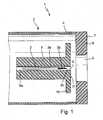
- FIGS. 1 and 2show diagrammatically the puncturing direction of the front end of a lancing system 1, which is not shown in its entirety.
- the lancing system 1comprises a puncturing device 2 and a needle element 3, also not completely shown.
- the lancing system 2has a housing 4 with a housing opening 5, which is arranged on the front wall 6 of the puncturing device.
- a minimum width of the housing opening 5has proved to be advantageous, which (in the case of a circular opening) corresponds to a diameter of at least 4 mm, particularly preferably at least 6 mm.
- the housing opening 5is circular and has a diameter of 4 to 11 mm, preferably from 6 to 8 mm. Even if it is not exactly circular, its cross-sectional area should correspond to the area of a circle with the mentioned diameter values. In any case, the opening is so large that the skin of a finger or another body part can bulge into the opening.
- One the Housing opening 5 enclosing housing skin contact surface 7is pressed in use on the skin of a body part.
- the needle element 3is formed as a cannula 3a, which has a capillary channel 3b and whose front end is chamfered such that a tip 3c is formed.
- the needle element 3, referred to as a sampler,is particularly preferably produced from a flat sheet metal and has a capillary channel 3b, preferably a capillary channel which is open on one side, through which a body fluid, in particular blood, can be taken up from the skin.
- the needle element 3is precisely guided relative to a lancing depth reference element 8, for example as shown in FIG. 1, in a guide channel 8a of the lancing depth reference element 8, which has an element opening 9 at the front, ie in the piercing direction of the needle element 3.
- the element opening 9is significantly smaller than the housing opening 5.
- the lancing depth reference element 8has in the example shown here at its front end two. Stops 10.
- the stops 10can of course also be formed at a different location of the reference element 8.
- Also at the front end of the lancing depth reference element 8is a reference skin contact surface 11 which is adapted to contact the skin of the body part.
- FIG. 1illustrates the starting position of the lancing system 1, in which the lancing depth reference element 8 is arranged in a rest position so as to be spaced from the edge of the housing 4.
- the lancing depth reference element 8is brought into its defined stationary position, in which it also remains when the tip 3a of the needle element 3 in the advancing phase of the lancing movement passes the reference skin contact surface 11 and emerges from the lancing depth reference element 8.
- This configurationreferred to as start position, is illustrated in more detail in FIG. 2a.
- Figures 2a to fshow different positions of use of the lancing system 1.
- the sequence of the lancing movementis shown in individual phases, wherein after reaching the reversal point of the lancing movement, the tip 3a of the needle 3 is retracted to a residual penetration or residual stitch depth.
- the needle element 3 and the reference Hautcardtläche 11move together while maintaining the supernatant of the needle element 3 via the reference skin contact surface 11 of the skin and relieve them such that blood can escape, the capillary channel 3b of the needle member 3 takes that Blood on.
- This movement phaseis called the collection phase.
- the lancing depth reference element 8In the starting position of the lancing system 1 (FIG. 2 a), the lancing depth reference element 8 is in its defined stationary position with respect to the housing 4.
- the defined stationary position of the lancing depth reference element 8can also be related to the housing skin contact surface 7.
- the stationary positionis achieved, for example, by the lancing depth reference element 8 interacting with its stop 10 against a corresponding housing stop 12 on the housing opening 5.
- the stationary position of the reference Hautmindertläche 11is now clearly defined by the contact with the stopper 10 with the housing stop 12. It is clear that the use of corresponding stops is only one way of arranging the lancing depth reference element 8 in the defined stationary position.
- the lancing depth reference element 8can also be movably mounted, wherein it can act against the stop 12 by means of a spring. It is only important that the stationary position is maintained in such a way that the stitch depth of the needle element 3 set and determined by the puncturing depth reference element 8 can be reliably ensured.
- the needle element 3In the stationary position of the lancing depth reference element 8, the needle element 3 is arranged such that its tip 3 c is arranged behind the reference skin contact surface 11. In the example shown the tip 3c is about 3 to 4 mm behind the reference skin contact surface 11.
- the lancing depth reference element 8 of the lancing system 1is therefore preferably already arranged in its stationary position before the lancing system 1 comes into contact with a body part 13, ie before the skin 14 of the finger 13 is pressed against the housing skin contact surface 7.
- the housing Hautorialt Structure 7has the task of squeezing the finger 13 so that in the bulged portion 13a of the finger 13, the blood is pressed.
- the reference skin contact surface 11not only limits the bulge of the finger 13, but also tightens the skin 14 in the region of the element opening 9 of the lancing depth reference element 8.
- the bloodis pressed into the region of the body part in which a wound should be generated.
- the penetration of the skinwhich is typically caused when the needle penetrates, is prevented by the tightening of the skin in this area.
- the stitchcan be triggered.
- the needle element 3then moves in the piercing direction and pierces the skin 14 of the finger 13 with its tip 3c, as shown in FIG. 2c.
- the tip 3cprotrudes around the set Penetration depth S of about 1.5 to 2.5 mm in the skin 14 inside. This defined as reversal point position is after about 1 msec. reached.
- the needle element 3is moved counter to the puncture direction until its tip 3c is retracted to a defined residual stitch depth R, which is about 0.5 mm and is reached after about 2 msec.
- the lancing depth reference element 8remains in its stationary position with its reference skin contact surface 11 and continues to rest against the skin 14.
- the two partial sections of the puncturing movement running to this pointie the puncture until reaching the reversal point of the puncturing movement at the puncture depth S and the withdrawal of the needle element 3 to the remaining puncture depth R, are preferably significantly faster than the subsequent subsections of the recirculation phase of the puncturing movement.
- the reference skin contact surface 11preferably remains in its stationary position (FIG. 2d).
- the puncturing depth reference element 8is moved counter to the puncturing direction.
- the lancing depth reference element 8is moved together with the needle element 3. This movement can be done at different speeds.
- the lancing depth reference element 8 and the needle element 3are moved synchronously on this part of the return phase such that the relative position between the tip 3c of the needle element 3 and the reference skin contact surface 11 of the lancing depth reference element 8 remains unchanged.
- the residual stitch depth Ris maintained while the lancing depth reference element 8 is moved away from the skin 14. This leads to a relaxation of the skin, which follows the lancing depth reference element 8 due to its viscoelasticity.
- the pressure of the lancing depth reference element 8however, the skin 14 in the area around the puncture is reduced to allow blood flow from the wound.
- the lancing depth reference element 8is thus moved in the manner of its stationary position relative to the housing skin contact surface 7 that the reference skin contact surface 11 remains in contact with the skin 14, wherein the movement takes place before the tip 3 c of the needle element 3 completely out of the Skin 14 is pulled out.
- the needle element 3 of the puncture depth reference element 8When the tip 3c of the needle element 3 has reliably left the skin 14 after approximately 0.5 to 3 seconds, the needle element 3 of the puncture depth reference element 8 is retracted to such an extent that the tip 3c is behind the reference skin contact surface 11.
- the sample obtained with the capillary channel 3bcan now be transferred to a test chemistry, for example to a sample carrier. In this case, the blood flows out of the capillary channel 3b of the needle element 3 onto the test carrier, not shown.
- the lancing system 1is removed from the skin 14.
- the skinno longer has any contact with the housing contact surface 7, as shown in FIG. 2g. This completes the lancing process.
- the needle element 3may be formed without capillary channel 3b.
- the lancing depth reference element 8is moved away from the housing opening 5 so far that an analysis unit with an analysis element can be moved to the housing opening 5 in order to collect blood emerging from the wound in the skin.
- the movement of the lancing movementis significantly different in this case.
- the puncturing movementcomprises only a fast propulsion phase until reaching the point of reversal and a rapid return phase until the needle element 3 has emerged from the skin.
- the puncture depth reference element 8is subsequently moved away from the housing opening 5, until it is no longer in contact with the skin and until there is sufficient space in the lancing device 2, that an analysis element can be guided against the skin to absorb the escaping blood.
- FIG. 3It has a puncturing drive 15a in the form of a drive unit 15, which comprises a tensioning rotor 16, a drive rotor 17 and a drive spring 19 and a motor (not shown here).
- the two rotorsare mounted on an axle 18.
- the arranged between the rotors drive spring 19serves to transmit the force and the moments of the tensioning rotor 16 on the drive rotor 17.
- the tensioning rotor 16 of Figure 3has a drive toothing 20 through which the tensioning rotor 16 can be driven by the motor of the drive unit 15.
- Such drive unitsare referred to as OWADAC drives.
- An example of such a driveis from the EP 1504718 known.
- the drive unit described thereis likewise suitable for realizing the lancing movement according to FIG.
- a arranged on the tensioning rotor 16 reference gate 21controls the lancing depth reference element 8 of the lancing system via a coupling mechanism, not shown here.
- the reference gate 21is preferably a narrow groove in which a control rider 35 (shown in FIGS. 4 and 5) is forcibly guided.
- the scenerycan also be a control curve, which is designed as a control edge or one-sided open groove. In it a tax rider can run spring-loaded, without a forced guidance of the tax rider arises.
- the tensioning rotor 16 with the reference link 21is part of a reference element drive 53. It also includes the drive rotor 17, the drive spring 18 and a reference element lever 30 described in more detail in connection with FIGS. 4 and 5.
- the lancing depth reference elementis moved by means of the reference element drive 53.
- the reference element drive 53is independent of the drive of the needle element 3. However, they can be at least partially coupled to one another and also have a common component, as is illustrated in FIG.
- the drive spring 19 in the present exampleis a common component of the two drives.
- the reference member drive 53may also be electrically, electronically or electromechanically separate from the drive of the needle member; also purely mechanical separations are possible.
- the drive rotor 17 of the drive unit 15is formed in two parts, wherein an inner adjustment member 22 relative to an outer rotor member 23 is axially adjustable by the adjustment of the two parts to each other, the puncture depth of the needle element 3 is defined and adjusted relative to the lancing depth reference element 8.
- a stitch gate 43which determines a part of the puncture path of the needle element and the reversal point of the puncturing movement, is partially obscured relative to the rotor part 23, depending on the position of the adjustment part 22.
- From the two-part design of the drive rotor 17also results in a two-part cam, which is formed from the stitch gate 43 and the lancet 27. Since the two-part control cam is variable in shape, it can not be designed as a closed, positively driven path.
- the control rider 33 on the lancet lever 29, which is guided in the two-part control cam,is therefore forced by a spring force (not shown) to follow the control edge of the control cam.
- the rotor part 23 of the drive rotor 17has on a part of an outer periphery a toothing 24, which during a part of the rotational movement with a gear 25 designed as a damper 26 so in Intervention comes that the movement of the drive rotor 17 is slowed down by the damper 26.
- the rotor part 23is formed on its (to the clamping rotor 16 aligned) underside in the form of a lancet 27, to effect via a coupling mechanism, the movement of the needle element.
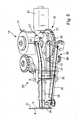
- FIGS 4 and 5each show a perspective view of a drive mechanism in which the drive unit 15 of Figure 3 is integrated.
- a coupling mechanism 28comprises a lancet lever 29, the reference element lever 30 and a coupling lever 31 and a bearing block 32.
- the lancet lever 29, the reference element lever 30 and the coupling lever 31are coupled to each other via the bearing block 32.
- An axial displacement of the bearing block 32, which is caused by one of the levers,is transmitted to the other levers at least partially so that simultaneous movement of the needle element 3 and the lancing depth reference element 8 can be made possible.
- the coupling mechanism 28the rotational movements of the drive unit 15 are transmitted to the lancing unit consisting of needle element 3 and lancing depth reference element 8 with reference skin contact surface 11.
- a control rider 33which is arranged and attached to one end of the lancet lever 29, drives off the lancet backdrop 27 and the stitch lug 43 of the drive rotor 17.
- the movement of the control rider 33is transmitted via the lancet lever 29 to the lancet or needle element 3, which is fastened to the lancet lever 29 by means of a coupling element 34.
- a coupling element 34is necessary in order to use the puncturing device several times.
- the coupling lever 31is moved via a control rider 35, which is guided along the reference link 21 of the tensioning rotor 16.
- the coupling lever 31is fixed to the bracket 32 that a through Departing the reference gate 21 caused movement of the coupling lever 31 causes an axial displacement of the bearing block 32 in and against the puncture direction.
- the axial movement of the bearing block 32causes movement of the lancing depth reference element 8 coupled to the reference element lever 30.
- This arrangementalso makes it possible to compress the reference skin contact surface 11 with respect to the housing 4 under a skin impression force, which is preferably approximately 3 N, without affecting the stitch depth and / or the residual stitch depth in the collection phase (collection depth).
- the bearing 57is held by a spring 56 designed as a spring means 58.
- the spring 56may be designed as a metal spring. This results in a resilient mounting of the bearing block 32 and thus ultimately a resilient mounting of the lancing depth reference element 8 with the arranged at its upper end reference skin contact surface eleventh
- the lancing depth reference element 8is movably mounted counter to the puncturing direction of the needle element 3.
- the spring 56presses the bearing 57 by its bias in the puncture direction.
- the deflection of the bearing 57 in the puncturing direction or the deflection of the coupling mechanism 28 in the puncturing directioncan be limited by a stop. It is also possible to limit the lancing depth reference element 8 itself by a stop, so that the spring travel exerted by the spring 56 is limited.
- the lancing depth reference element 8When pressing the skin against the reference skin contact surface 11, the lancing depth reference element 8 is displaced against the force of the spring 56 against the puncture direction to the rear, wherein the spring 56 is compressed. The pressure force acting on the skin then corresponds to the spring force of the spring means 58. In this way, a limitation of the maximum allowable pressure on the skin can be achieved.
- FIGS. 4 and 5also show that the lancing depth reference element 8 and the needle element 3 can each be disposable elements. Preferably, they are replaced together, wherein the lancing drive 15 and the coupling mechanism 28 can be used multiple times.
- a lancing depth reference element 8 without an element opening 9is shown. It may, for example, be a substantially planar element which can simultaneously fulfill the function of an analysis element and whose upper edge forms the reference skin contact surface 11.
- the needle element 3is then guided along the lancing depth reference element 8 during the lancing movement and passes through the reference skin contact surface 11.
- the minimum distance, ie the smallest distance, between the reference skin contact surface 11 and the needle element 3is at most 1 mm, preferably at most 0.5 mm. The relatively small distance ensures that the needle element 3 pierces into a region of the skin that is tautened by the reference skin contact surface 11.
- FIGS. 6a to iThe movement sequence of the drive unit 15 for realizing the piercing movement described in FIG. 2 is shown in detail in FIGS. 6a to i. In this case, various positions of the clamping rotor 16 are shown with respect to the drive rotor 17.
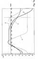
- FIGS 7a and bshow a geometric representation of the caused by the scenes of the clamping rotor 16 and the drive rotor 17 strokes of the lancing unit connected to the end of the lancet lever 29 and the reference element lever 30.
- the curve Ashows the stroke of the reference element lever 30, which is the position of the lancing depth reference element 8 corresponds.
- the curve Bshows the stroke caused by the lancet 27; the short C caused by the Stichkullise 43 stroke.
- the curve Dis the resulting curve (representing the stroke of the needle element 3).
- Figure 6ashows the starting position of the two rotors 16,17, which is denoted by 0 °.
- the drive rotor 17rests with a retaining cam 36 on a latching hook 37 of a latching 38, so that the movement of the drive rotor 17 in the arrow direction, ie counterclockwise, is locked.
- the tensioning rotor 16is now rotated by a drive motor 42 shown in Figures 4 and 5 counterclockwise.
- the drive spring 19 between the tensioning rotor 16 and the drive rotor 17is stretched over its tension slowly out (Figure 6b).
- the lancing depth reference element 8 coupled via the coupling mechanism 28is moved into its defined stationary position (compare FIG.
- the needle element 3is moved together with the lancing depth reference element 8, so that the relative position of the two remains constant to one another.
- the lancing depth reference element 8Approximately after a 90 ° rotation of the clamping rotor 16 (curve A, Figure 7a, b), the lancing depth reference element 8 has reached its defined stationary position.
- the rotational movement of the drive rotor 17is transmitted to the lancet lever 29 moved by the lancet link 27 so that the needle element 3 is driven by relaxing the drive spring 19.
- the needle element 3is now guided in a rapid movement in the piercing direction until it reaches the reversal point and then retracted to the residual stitching depth R.
- the reversal point of the piercing movementis achieved approximately at a rotation of the drive rotor 17 to 90 °.
- FIG. 6hshows the rotational position of approximately 270 ° at which the retraction of the needle element 3 into the puncturing depth reference element 8 begins.
- the curve D of the needle element of Figure 7approaches the curve A of the lancing depth reference element 8 and finally cuts them at about 290 °.
- the needle element 3is drawn into the lancing depth reference element 8. Now, both are returned to their rest positions, which is achieved at a rotor position of 360 ° ( Figure 6i).
- FIG. 7ashows the minimally set stitch depth
- FIG. 7bshows the maximum stitch depth set.
- the curve C of FIG. 7bis shifted with respect to the curve C of FIG. 7a. This shift is due to an axial displacement of the adjusting member 22 relative to the rotor member 23, which is shown in detail in Figures 8a to d, the rotors upside down, so that the position in space corresponds to the other figures.
- the minimum stitch depthis about 0.75 mm, the maximum stitch depth about 2.3 mm.
- the tensioning rotor 16is first moved until it has reached a rotational position of 180 °, the lancing depth reference element 8 is raised by 3 mm during the movement. At the same time the needle element is raised by this stroke of 3 mm.
- the resulting movement curve of the needle element 3corresponds to the triggering of the engraving, ie from the moment in which the drive rotor 17 moves, first the curve B to a later rotation angle, the axially adjustable curve C takes the lead and the course of Curve D determined From this angle of rotation, the control rider 33 follows the stitch gate 43 of the adjusting part 22. From the point at which the curve C lags behind the curve B again, the curve leads B again, that is, the lancet gate 27 takes over again the leadership of the tax rider 33rd
- the lancet gate 27influences the control rider 33 such that the needle element 3 again follows the control curve B in parallel.
- the needle element 3is thus moved back relative to the lancing depth reference element 8 until it is drawn into the lancing depth reference element 8.
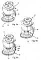
- Figures 8a and bshow the rotated by 180 ° drive unit 15 (from below) in different positions of the adjustment member 22 with respect to the rotor part 23 of the drive rotor 17.
- Figure 8ashows the setting of the minimum stitch depth.
- the adjustment part 22is axially offset downwards relative to the rotor part 23, that is to say away from the tensioning rotor 16.
- Figure 8cwhich shows a side view of the drive setting the minimum stitch depth
- the lancet gate 27 and the stitch gate 43are shown, which are responsible for the movement of the needle element.
- the backdrop 43projects only slightly beyond the lancet backdrop, so that the needle or lancet also penetrates only slightly into the skin.
- Figures 8b and dshow the drive unit 15 in the setting of the maximum stitch depth.
- the adjusting part 22is displaced axially relative to the rotor part 23 in the direction of the clamping rotor 16.
- the control rider for controlling the movement of the lancetis guided by the link 43, which is clearly lifted relative to the lancet link 27 resulting in a large stitch depth.
- the gate 43determines the movement of the needle element 3 during the entire propulsion phase and the fast-running part of the return phase.
- FIG. 9shows a puncture depth reference element 8, which is formed with a two-part closure 44 with an element opening 9.
- the tip 3c of the needle element 3passes in the advancing phase of the lancing movement.
- the element opening 9is advantageously variable in size. It can also be reduced so far that the lancing depth reference element 8 is closed.
- the element opening 9 of the lancing depth reference element 8is dimensioned such that the skin resting against the reference skin contact surface 11 is tightened.
- the minimum distance between the reference skin contact surface 11 and the needle element 3is generally, as described above for a lancing depth reference element without element opening, at most 1.5 mm, preferably at most 1 mm, particularly preferably at most 0.5 mm. If this smallest distance between the reference skin contact surface 11 and the needle element 3 is maintained; This results in lancing depth reference elements 8 with an element opening 9 a corresponding opening cross-section.
- the cross-section of the element opening 9is dimensioned such that, in the case of a circular opening, the cross section corresponds to a diameter of at most 3 mm, particularly preferably of at most 2 mm.
- Non-circular element openings 9have a corresponding cross section. Possible likewise preferred cross-sectional shapes of the element opening are four- or polygonal cross-sections, particularly preferred are openings with a rhombic cross-section.
- the lancing depth reference element 8consists of a plurality of components.
- the reference skin contact surface 11is preferably formed on the plurality of components that are movable relative to each other to change the size of the element opening 9.
- the components of the lancing depth reference elementare moved in such a way that they have a movement component perpendicular to the puncturing direction of the lancing movement.
- An example of such a puncture depth reference element 8is, for example, a pinhole with a variable hole cross-section.
- the two-part closure 44 in FIGS. 9a to chas the two closure elements 45 and 46.
- the closure elements 45 and 46can be moved against each other so that the closure 44 can be completely closed ( Figure 9a).
- the completely closable lancing depth reference element 8can then close the entire lancing system 1 when the lancing depth reference element 8 abuts closing and / or sealing against the housing opening 5 of the lancing device 2.
- FIG. 9bshows the closure 44 of the lancing depth reference element 8 with a small element opening 9, through which the needle element 3 can emerge.
- FIG. 9cshows the completely opened closure 44, in which the two closure elements 45 and 46 are spaced apart from one another.
- An element opening 9 having a very large cross-sectionis formed, so that the blood can be collected from the wound after the puncture.
- an analysis unit for receiving the Drops of bloodare placed in the element opening 9 and the exiting blood reach a sample carrier.
- FIG. 10 ashows the opened closure, in which the two closure elements 45, 46 are spaced apart from one another.
- the closure elements 45,46are moved towards each other, wherein the closure member 46 against the closure member 45 and this presses against the housing 4, so that the housing opening 5 is closed.
- FIGS. 11 a, b and 12 a, bshow further embodiments of a lancing depth reference element 8 designed as a closure 44.
- the multipart closurehas an element opening 9.
- the closure parts 47are moved radially outward by turning the closure 44 in order to enlarge the element opening 9.
- the spring-loaded closure parts 47are held together by a clamp 48, which can be adjusted via a spindle 49.
- a clamp 48When the clamp 48 is expanded, the closure members 47 are moved radially outward and the element opening 9 is enlarged, Figure 12b.
- Figures 13a, bshow a two-part formed lancing depth reference element 8, the two closure elements 50,51 can be pivoted about a hinge 52 against each other.
- the element opening 9is enlarged, so that after the piercing movement of the lancet or the needle element, a large opening area is released, into which also an analysis unit can be moved in order to receive blood emerging after the puncture from the wound ,
- the lancing depth reference elements 8 with variable element openings 9 shown in FIGS. 9 to 13are particularly suitable for Blood collection methods in which the sample is not picked up by the needle element but collects at the skin surface to be directly picked up by an analysis element.
- Such blood collection methodsare performed with a lancing system 1, which also has an analysis unit 54 in addition to a lancing unit.
- the analysis unit 54has at least one analysis element 55 for receiving the liquid, which is preferably the blood exiting from the finger 13.
- An analysis contained in the blood, in particular the glucose,is determined in the analysis unit 54.
- FIG. 14shows, by way of example, a lancing system 1 with an analysis unit 54 which is arranged in a lancing device 2. Behind the housing opening 5 of the lancing device 2, a multi-part lancing depth reference element 8 is arranged, which is designed in the form of the two-part closure 44 known from FIG.
- the blood collection processis significantly different with the puncture device 2 as it is described in Figures 2, 6 and 7.
- the needle element 3moves quickly during its lancing in the propulsion phase, as well as in the return phase. So it pierces quickly into the finger 13 and withdraws as quickly completely back out of it.
- the lancing depth reference element 8is largely closed, so that only one element opening 9 is formed, whose cross section corresponds to a round cross section of about 2 mm diameter.
- the shutter members 45 and 46are respectively moved sideways in the arrow direction, so that the element opening 9 is enlarged.
- the element opening 9is then widened so far that it corresponds at least to the housing opening 5.
- the movement apart of the closure elements 45 and 46 of the lancing depth reference element 8has the result that the finger 13 bulges further into the housing opening 5.
- the back pressure exerted by the puncture depth reference element 8 against the finger 13is reduced or canceled.
- the blood leakage from the woundis no longer prevented.
- the blood collected in the skin of the fingercan come out of the puncture wound. It is thus achieved an expression-promoting effect through the housing-skin contact surface 7.
- the exiting bloodis ready to be picked up by the analysis element 55.
- the analysis unit 54is moved in the direction of the housing opening 5 in such a way that the blood emerging from the puncture wound can be picked up by the analysis element 55.
- the two closure elements 45 and 46are moved laterally with respect to the puncturing direction, wherein the lateral movement is defined by having a component of movement perpendicular to the puncture direction.
- the analysis unit 54is preferably moved so that it has a movement component parallel to the puncturing direction of the needle element 3.
- their movementcan also have perpendicular to the puncture direction oriented motion components.
- the analysis unit 54is moved parallel to the piercing direction of the needle element 3. On the path of movement of the analysis unit, it is moved from a starting position to a position behind the housing opening 5, the analysis unit then can also press against the 13 acting in the housing opening fingers 13.
- the lancing depth reference element 8is designed as one piece even with a lancing device 2 with integrated analysis unit 54.
- the lancing depth reference element 8is preferably also moved sideways away from the housing opening 5, wherein the movement has a movement component oriented perpendicular to the puncturing direction. The movement can therefore also be made obliquely backwards.
Landscapes
- Health & Medical Sciences (AREA)
- Life Sciences & Earth Sciences (AREA)
- Physics & Mathematics (AREA)
- Public Health (AREA)
- Biophysics (AREA)
- Pathology (AREA)
- Engineering & Computer Science (AREA)
- Biomedical Technology (AREA)
- Heart & Thoracic Surgery (AREA)
- Medical Informatics (AREA)
- Molecular Biology (AREA)
- Surgery (AREA)
- Animal Behavior & Ethology (AREA)
- General Health & Medical Sciences (AREA)
- Veterinary Medicine (AREA)
- Hematology (AREA)
- Dermatology (AREA)
- Pain & Pain Management (AREA)
- Emergency Medicine (AREA)
- Optics & Photonics (AREA)
- Measurement Of The Respiration, Hearing Ability, Form, And Blood Characteristics Of Living Organisms (AREA)
- Surgical Instruments (AREA)
- Adornments (AREA)
- External Artificial Organs (AREA)
- Dental Tools And Instruments Or Auxiliary Dental Instruments (AREA)
- Measuring And Recording Apparatus For Diagnosis (AREA)
- Treatment Of Water By Ion Exchange (AREA)
- Detergent Compositions (AREA)
Abstract
Description
Translated fromGermanDie Erfindung betrifft ein Stechsystem zur Entnahme einer Körperflüssigkeit aus der Haut eines Menschen oder Tieres. Das Stechsystem besteht aus einem Nadelelement zum Einstechen in die Haut und einem Stechgerät, das einen Stechantrieb einschließt. Durch den Stechantrieb wird eine Stechbewegung mittels eines Kopplungsmechanismus mit dem Stechantrieb gekoppelten Nadelelement in Einstichrichtung angetrieben.The invention relates to a lancing system for removing a body fluid from the skin of a human or animal. The lancing system consists of a needle element for piercing the skin and a lancing device, which includes a lancing drive. By the lancing drive a piercing movement is driven by means of a coupling mechanism with the lancing drive coupled needle element in the puncture direction.
Die mit dem Stechsystem gewonnene Körperflüssigkeit ist in der Regel Blut. In manchen Anwendungsfällen werden aber auch Proben von interstitieller Flüssigkeit gewonnen. Wenn nachfolgend Blut als Beispiel einer Körperflüssigkeit erwähnt wird, ist dies keine Beschränkung der Allgemeinheit. Blut steht nur als Beispiel für jede andere aus der Haut entnehmbare Körperflüssigkeit.The body fluid obtained with the lancing system is usually blood. In some applications, however, samples of interstitial fluid are also obtained. When blood is mentioned below as an example of a bodily fluid, this is not a limitation to the general public. Blood is only an example of any other bodily fluid that can be removed from the skin.
Für Diagnosezwecke werden geringe Mengen von Blut aus einem Körperteil, beispielsweise aus dem Finger oder dem Ohrläppchen, entnommen. Hierzu werden Lanzetten verwendet, die mit ihrer Spitze eine Wunde in das entsprechende Körperteil stechen. Der Einstich der Lanzette in die Haut geschieht entweder durch besonders trainiertes Personal, das den Einstich manuell vornimmt, oder durch besondere Blutentnahmesysteme, die sogenannte Stechgeräte und zugehörige Lanzetten einschließen.For diagnostic purposes, small amounts of blood are removed from a body part, for example from the finger or earlobe. For this purpose, lancets are used, which pierce a wound with its tip into the corresponding body part. The puncture of the lancet into the skin is done either by specially trained personnel who makes the puncture manually, or by special blood collection systems, the so-called lancing devices and associated lancets include.
Bei einfachen Stechgeräten wird die Lanzette in einer schnellen Bewegung in die Haut hinein und nach Erreichend es Umkehrpunkts aus ihr wieder herausgezogen. Anschließend wird das Stechgerät entnommen. Der Benutzer massiert dann die Haut im Bereich der Einstichstelle und drückt sie zusammen, um den Blutaustritt aus der Haut zu fördern. Dieses als "Melken" bezeichnete Zusammendrücken der Haut wird so lange fortgesetzt, bis ein genügend großer Blutstropfen aus der Haut heraustritt. In einem weiteren Schritt wird der Blutstropfen auf einen Teststreifen gebracht, um die Konzentration eines in dem Blut vorhanden Analyten, insbesondere den Glucosewert, zu bestimmen. Dieses Vorgehen ist für den Benutzer jedoch umständlich und auch unangenehm, da er die Haut in der Nähe der Wunde zusammenquetschen muss.In simple lancing devices, the lancet is pulled out of the skin in a rapid movement and, after reaching the reversal point, it is pulled out of it again. Then the lancing device is removed. The user then massages the skin around the puncture site and compresses it to promote blood leakage from the skin. This squeezing of the skin, referred to as "milking," is continued until a sufficiently large drop of blood emerges from the skin. In a further step, the blood drop is placed on a test strip to determine the concentration of an analyte present in the blood, in particular the glucose value. However, this procedure is inconvenient for the user and also unpleasant because he has to squeeze the skin near the wound.
Insbesondere für Diabetiker, die sich mehrmals am Tag in die Haut stechen müssen, um den Glucosegehalt im Blut zu bestimmen, ist ein möglichst schmerzfreies Stechen wichtig. Ebenso wichtig ist eine vereinfachte Handhabung der Blutentnahme. Gerade das als unangenehm empfundene "Melken" sollte vermieden werden. Aus diesem Grund wurden mehrere Stechgeräte im Stand der Technik entwickelt, die eine große Austrittsöffnung für die Lanzette mit einem Durchmesser von mehreren Millimetern aufweisen. Das die Austrittsöffnung ringförmig umschließende vordere Ende des Gehäuses bildet eine Gehäuse-Hautkontaktrläche, die gegen die Haut gedrückt wird. Infolge des Drucks wölbt sich die Haut in die Öffnung des Stechgerätes hinein. Gleichzeitig wird durch den ausgeübten Anpressdruck der Innendruck im Finger (bzw. anderen Körperteil) erhöht, so dass bei einem Einstechen der Lanzette in die Haut die Körperflüssigkeit bzw. das Blut spontan austritt, ohne dass ein manuelles Massieren oder "Melken" notwendig ist. Derartige Produkte werden nachfolgend als "Stechsystem mit Expressionshilfe" bezeichnet.In particular, for diabetics who have to stab themselves several times a day in the skin to determine the glucose level in the blood, as painless as possible stinging is important. Equally important is a simplified handling of blood collection. Especially the perceived as "milking" should be avoided. For this reason, several prior art lancing devices have been developed that have a large lancing aperture with a diameter of several millimeters. The outlet end annularly surrounding the front end of the housing forms a housing skin contact surface which is pressed against the skin. As a result of the pressure, the skin bulges into the opening of the lancing device. At the same time, the internal pressure in the finger (or other body part) is increased by the applied contact pressure, so that when the lancet pierces the skin, the body fluid or blood spontaneously escapes without the need for manual massaging or "milking". Such products are referred to below as "puncture system with expression aid".
Es ist bereits seit längerem bekannt, dass das Schmerzempfinden wesentlich von der Reproduzierbarkeit der Stichtiefe beeinflusst wird. Mit anderen Worten soll die Tiefe des Einstichs bei einer Mehrzahl von zeitlich getrennten Stechvorgängen (aber unveränderter Einstellung des Stechgerätes) möglichst gleich bleiben, um mit einer minimalen Stichtiefe eine ausreichende Blutmenge zu erzeugen (
Bei gegebener Qualität des Stechantriebes hängt die Reproduzierbarkeit der Stichtiefe entscheidend davon ab, dass die Position der Haut während des Stichs reproduzierbar definiert ist. Diesbezüglich bestehen bei Stechsystem mit Expressionshilfe besondere Probleme, weil das Einwölben der Haut von der Beschaffenheit der Haut abhängig ist und deshalb von Benutzer zu Benutzer variiert. Darüber hinaus verändert die Haut ihre Eigenschaften auch bei einzelnen Benutzern beispielsweise in Abhängigkeit davon, ob sie trocken oder feucht bzw. kalt oder warm ist. Deswegen stellt die Gehäuse-Hautkontaktfläche am Innenrand der Gehäuseöffnung nur eine ungenaue Referenz für die Einstichtiefe dar.Given the quality of the puncture drive, the reproducibility of the puncture depth depends crucially on the fact that the position of the skin during the sting is reproducibly defined. In this regard, there are particular problems with the puncture system with expression aid, because the invagination of the skin is dependent on the nature of the skin and therefore varies from user to user. In addition, the skin changes its properties even with individual users, for example, depending on whether it is dry or humid or cold or warm. Therefore, the housing-skin contact surface on the inner edge of the housing opening is only an inaccurate reference for the penetration depth.
Zur Lösung dieses Problems wird in der
Gemäß einer Reihe weiterer bekannter Vorschläge sollen Funktionsverbesserungen, unter anderem hinsichtlich der Reproduzierbarkeit der Stichtiefe, dadurch erreicht werden, dass ein Stechtiefenkontrollelement gemeinsam mit einer Nadel schnell auf die Haut zubewegt wird, wobei durch den Impuls beim Auftreffen auf die Haut positive Wirkungen erreicht werden sollen.According to a number of other known proposals, functional improvements, inter alia with regard to the reproducibility of the stitch depth, are to be achieved by rapidly moving a lancing depth control element together with a needle to the skin, wherein positive effects are to be achieved by the impulse when hitting the skin.
Beispielsweise offenbart die
Ein vom Prinzip her ähnliches Stechgerät ist in
Auf dieser Grundlage ist es Aufgabe der Erfindung, ein Stechsystem vorzuschlagen, bei dem das Blut nach dem Einstich ohne zusätzliche Handhabungsschritte aus der Haut austritt und der Einstich für den Patienten möglichst schmerzarm erfolgt Ein derartiges System soll die im Stand der Technik bekannten Nachteile überwinden.On this basis, it is the object of the invention to propose a lancing system in which the blood exits the skin after the puncture without additional handling steps and the puncture for the patient is as painless as possible. Such a system is intended to overcome the disadvantages known in the prior art.
Die Aufgabe wird gelöst durch ein Stechsystem zur Entnahme einer Körperflüssigkeit aus der Haut eines Körperteils eines Menschen oder Tieres mit den Merkmalen gemäß Anspruch 1.The object is achieved by a lancing system for removing a body fluid from the skin of a body part of a human or animal having the features according to
Das Stechsystem umfasst ein Nadelelement zum Einstechen in die Haut und ein Stechgerät, das einen Stechantrieb einschließt. Durch den Stechantrieb wird eine Stechbewegung des Nadelelementes, das mittels eines Kopplungsmechanismus mit dem Stechantrieb gekoppelt ist, in Einstichrichtung angetrieben. Das Stechgerät hat ein Gehäuse mit einer Gehäuseöffnung an seinem in Einstichrichtung vorderem Ende. Die Gehäuseöffnung wird von einer Gehäuse-Hautkontaktfläche umgeben, die bei der Benutzung des Stechgerätes gegen die Haut des Körperteils gedrückt wird.The lancing system includes a needle element for piercing the skin and a puncturing device that includes a lancing drive. By the lancing drive a piercing movement of the needle element, which is coupled by means of a coupling mechanism with the lancing drive, driven in the puncture direction. The puncturing device has a housing with a housing opening at its front end in the piercing direction. The housing opening is surrounded by a housing-skin contact surface, which is pressed when using the lancing device against the skin of the body part.
Das Nadelelement wird in einer Vortriebsphase der Stechbewegung auf einem vorbestimmten Einstichweg in einer Einstichrichtung bewegt, bis seine Spitze in die Haut eindringt, um eine Wunde zu erzeugen. In einer Rückführungsphase der Stechbewegung nach Erreichen eines der Stichtiefe in die Haut entsprechenden Umkehrpunktes wird das Nadelelement wieder zurückgezogen. Ein vorgegebener Wert der Stichtiefe wird durch ein Stechtiefenreferenzelement mit einer Referenz-Hautkontaktfläche gewährleistet, wobei das Stechtiefenreferenzelement so ausgebildet und angeordnet ist, dass die Referenz-Hautkontaktfläche am Umkehrpunkt der Stechbewegung mit der Haut in Kontakt steht. Der vorgegebene Wert der Stichtiefe wird durch den Abstand in Einstichtiefe zwischen der Referenz-Hautkontaktfläche und der Position der Spitze des Nadelelements an dem Umkehrpunkt der Stechbewegung bestimmt.The needle member is moved in a driving phase of the piercing movement on a predetermined insertion path in a puncture direction until its tip penetrates into the skin to create a wound. In a return phase of the puncturing movement after reaching the puncture depth in the skin corresponding reversal point, the needle element is retracted again. A predetermined value of the stitch depth is ensured by a lancing depth reference element with a reference skin contact surface, wherein the lancing depth reference element is designed and arranged such that the reference skin contact surface is in contact with the skin at the point of reversal of the lancing movement. The default value The puncture depth is determined by the distance in penetration depth between the reference skin contact surface and the position of the tip of the needle element at the reversal point of the lancing movement.
Das Stechtiefenreferenzelement mit der Referenz-Hautkontaktfläche befindet sich zu dem Zeitpunkt, zu dem die Spitze des Nadelelements in der Vortriebsphase der Stechbewegung die Referenz-Hautkontaktfläche passiert und in eine mit dieser in Kontakt stehenden Hautoberfläche eindringt, in einer definierten stationären Position in Bezug auf den Umkehrpunkt der Stechbewegung. Außerdem ist das Stechtiefenreferenzelement derartig ausgebildet und angeordnet, dass eine Deformationsstabilisierung der gegen sie gedrückten Hautoberfläche erreicht wird. Durch diese Deformationsstabilisierung wird bewirkt, dass die Reproduzierbarkeit der Stichtiefe nicht in einem praktisch störenden Ausmaß dadurch beeinträchtigt wird, dass die Haut lokal deformiert ("eingedellt") wird, wenn die Spitze der Lanzette in sie eindringt.The lancing depth reference member having the reference skin contact surface is located at a defined stationary position with respect to the point of reversal at the time when the tip of the needle member passes the reference skin contact surface in the advancing phase of the lancing motion and penetrates into the skin surface in contact therewith the piercing movement. In addition, the lancing depth reference element is designed and arranged such that a deformation stabilization of the skin surface pressed against it is achieved. This deformation stabilization causes the puncture depth reproducibility not to be adversely affected to a practically inconvenient extent by locally deforming ("denting") the skin as the tip of the lancet penetrates into it.
Die Erfindung befasst sich primär mit dem Problem, die tatsächlich für die Stichtiefe relevante Position der Hautoberfläche möglichst gut reproduzierbar zu definieren und gleichzeitig einen zuverlässig ausreichenden Blutaustritt ohne zusätzliches "Melken" des Fingers zu gewährleisten. Sie zeichnet sich insbesondere dadurch aus, dass folgende zwei Maßnahmen miteinander kombiniert werden:
- a) Das Stechtiefenreferenzelement wird - im Gegensatz zu den vorstehend erörterten bekannten Stechsystemen - nicht gemeinsam mit der Nadel bewegt, sondern es befindet sich in einer fixen (stationären) Position relativ zu dem Umkehrpunkt des Stechgerätes. Dies gilt zumindest zum Zeitpunkt des Einstichs, also wenn die Spitze des Nadelelementes in der Vortriebsphase der Stechbewegung die Referenz-Hautkontaktfläche passiert. Vorzugsweise bleibt das Referenzelement mindestens bis zu dem Zeitpunkt, zu dem das Nadelelement den Umkehrpunkt seiner Stechbewegung erreicht, in der stationären Position. Besonders bevorzugt befindet sich das Stechtiefenreferenzelement während der gesamten Vortriebsphase der Stechbewegung des Nadelelementes, also vom Auslösen der Stechbewegung bis zum Erreichen des Umkehrpunktes, in seiner definierten stationären Position.
Wenn der Stechantrieb in dem Gehäuse des Stechgerätes starr fixiert ist, ist die Position des Umkehrpunktes der Stechbewegung, bezogen auf das Gehäuse, fix und folglich das Referenzelement auch bezogen auf das Gehäuse stationär. Gemäß einer bevorzugten Ausführungsform der Erfindung, die weiter unten noch näher erläutert wird, ist jedoch vorgesehen, dass das Stechtiefenreferenzelement und mindestens ein Teil des Stechantriebs derartig gemeinsam federnd gelagert sind, dass sie bei Druck auf die Referenz-Hautkontaktfläche eine synchrone Bewegung mit gleichbleibendem Abstand in Einstichrichtung ausführen können. In diesem Fall ist das Stechtiefenreferenzelement mit der Hautkontaktfläche bezogen auf das Gehäuse nicht stationär, jedoch weiterhin stationär bezogen auf den Umkehrpunkt der Stechbewegung. Auch in diesem Fall befindet sich das Stechtiefenreferenzelement jedoch während der gesamten Vortriebsphase der Stechbewegung des Nadelelementes auch relativ zu dem Gehäuse in einer praktisch stationären Position, weil eventuelle durch Variation des Druckes auf die Referenz-Hautkontaktfläche verursachte Bewegungen des Referenzelementes (und des mit diesem gemeinsam federnd gelagerten Teils des Stechantriebs) sehr viel langsamer als die Stechbewegung in ihrer Vortriebsphase sind. - b) Das Stechtiefenreferenzelement ist derartig ausgebildet und angeordnet, dass beim Andrücken der Haut an die Referenz-Hautkontaktfläche eine Deformationsstabilisierung erreicht wird Mit diesem Begriff wird eine Straffung der Haut bezeichnet, durch die verhindert wird, dass die Reproduzierbarkeit der Stichtiefe durch eine beim Einstechen der Spitze des Nadelelementes in die Haut auftretende Hautdeformation in störender Weise beeinträchtigt wird. Dies wird insbesondere dadurch gewährleistet, dass eine hinreichend hohe, "deformationsstabilisierende" Druckkraft während des Einstichs zwischen der Referenz-Hautkontaktfläche und der Haut wirkt.
- a) The lancing depth reference element is - in contrast to the above-discussed known lancing systems - not moved together with the needle, but it is in a fixed (stationary) position relative to the turning point of the lancing device. This applies at least at the time of the puncture, that is, when the tip of the needle element in the advancing phase of the lancing movement passes the reference skin contact surface. Preferably, the reference element remains in the stationary position at least until the moment when the needle element reaches the reversal point of its puncturing movement. Particularly preferably, the puncturing depth reference element is located during the entire propulsion phase of the puncturing movement of the needle element, ie from the triggering of the puncturing movement to reach the turning point, in its defined stationary position.
If the lancing drive is rigidly fixed in the housing of the lancing device, the position of the turning point of the puncturing movement, relative to the housing, fixed and thus the reference element also with respect to the housing stationary. According to a preferred embodiment of the invention, which will be explained in more detail below, however, it is provided that the lancing depth reference element and at least a portion of the lancing drive are mounted so resiliently together that when pressure on the reference skin contact surface a synchronous movement with a constant distance in Can perform piercing direction. In this case, the lancing depth reference element with the skin contact surface is not stationary relative to the housing, but still stationary with respect to the reversal point of the lancing movement. Also in this case, the lancing depth reference element is, however, during the entire propulsion phase of the piercing movement of the needle element also relative to the housing in a practically stationary position, because any movements of the reference element caused by variation of the pressure on the reference skin contact surface (and springing together with this stored part of the lancing drive) are much slower than the lancing movement in its propulsion phase. - b) The lancing depth reference element is designed and arranged in such a way that a deformation stabilization is achieved when the skin is pressed against the reference skin contact surface. This term refers to a tightening of the skin, which prevents the puncture depth from being reproduced by puncturing the tip The skin deformation occurring in the skin of the needle element is impaired in a disturbing manner. This is ensured, in particular, by the fact that a sufficiently high "deformation-stabilizing" pressure force acts during the puncture between the reference skin contact surface and the skin.
In mehreren oben diskutierten Dokumenten des Standes der Technik wird es als vorteilhaft angesehen, wenn das Stechtiefenreferenzelement gemeinsam mit dem Nadelelement in Richtung auf die Haut bewegt wird und mit einem erheblichen Impuls auf die Haut auftrifft. Im Rahmen der vorliegenden Erfindung wurde festgestellt, dass bei diesen bekannten Konstruktionen das Auftreffen des Referenzelementes auf die Haut eine teilelastische Stoßwirkung verursacht, durch die der Einstichschmerz erhöht wird. Dieser erhöhte Schmerz wird nach den vorliegenden Erkenntnissen nicht etwa direkt durch das Auftreffen des Referenzelementes verursacht, sondern ist eine indirekte Wirkung, die mit einer durch den teilelastischen Stoß verursachten Unruhe der Lanzettenbewegung zusammenhängt. Dieses Problem wird bei der vorliegenden Erfindung durch die stationäre Positionierung des Stechtiefenreferenzelementes vermieden.In several prior art documents discussed above, it is considered advantageous if the lancing depth reference element is moved together with the needle element in the direction of the skin and impinges with a significant impulse on the skin. In the context of the present invention, it has been found that, in these known constructions, the impact of the reference element on the skin causes a partially elastic impact effect which increases puncture pain. According to the available findings, this increased pain is not directly caused by the impact of the reference element, but is an indirect effect, which is connected with a restlessness of the lancet movement caused by the partially elastic impact. This problem is avoided in the present invention by the stationary positioning of the lancing depth reference element.
Eine wesentliche Verbesserung gegenüber der oben diskutierten
- a) Mittels eines Kraftsensors, der die Druckkraft misst. Die gemessene Druckkraft kann dem Benutzer auf, einem Display angezeigt werden, so dass dieser den Stich auslöst, wenn die Druckkraft zwischen einem Mindest- und einem Höchstwert liegt. Selbstverständlich kann die Auslösung auch automatisch erfolgen. Der Drucksensor ist vorteilhaft mit dem Stechfiefenreferenzelement gekoppelt. Beispielsweise kann das Stechtiefenreferenzelement einen Drucksensor aufweisen, mittels dessen der Anpressdruck ermittelt wird. Der Sensor kann mechanisch, elektrisch oder optisch ausgeführt sein. Es sind auch weitere sensorische Einrichtungen denkbar, die den Anpressdruck der Haut an die Referenz-Hautkontaktfläche ermitteln. Sie müssen nicht zwangsläufig mit dem Stechtiefenreferenzelement gekoppelt sein.
- b) Das Stechtiefenreferenzelement kann zur Gewährleistung der gewünschten hautstabilisierenden Druckkraft beweglich gelagert sein, wobei es mittels einer Federeinrichtung in Einstichrichtung derartig gegen einen gehäusefesten Anschlag gedrückt wird, dass es beim Andrücken der Haut gegen seine Referenz-Hautkontaktfläche von dem Anschlag abgehoben und gegen die Kraft der Federeinrichtung entgegen der Einstichrichtung so nach hinten verschoben wird, dass die auf die Haut wirkende Druckkraft der Federkraft der Federeinrichtung entspricht. Dabei sollte die Kraft der Federeinrichtung möglichst stabil sein. Dies lässt sich beispielsweise durch eine vorgespannte Metallfeder mit einer im Bewegungsbereich des Stechtiefenreferenzelementes flachen Federkennlinie, aber beispielsweise auch mittels einer Gasfeder erreichen.
- a) By means of a force sensor, which measures the pressure force. The measured compressive force may be displayed to the user on a display so that it triggers the stitch when the compressive force is between a minimum and a maximum value. Of course, the release can also be done automatically. The pressure sensor is advantageously coupled to the piercing reference element. For example, the lancing depth reference element may comprise a pressure sensor, by means of which the contact pressure is determined. The sensor can be mechanical, electrical or optical. There are also other sensory devices conceivable that determine the contact pressure of the skin on the reference skin contact surface. They do not necessarily have to be coupled to the lancing depth reference element.
- b) The lancing depth reference element can be movably mounted to ensure the desired skin-stabilizing pressure force, whereby it is pressed by a spring device in the puncture direction against a housing-fixed stop that it lifted when pressing the skin against its reference skin contact surface of the attack and against the force of Spring device is moved against the puncture direction to the rear, that the force acting on the skin pressure force of the spring force of the spring device corresponds. The force of the spring device should be as stable as possible. This can be achieved for example by a preloaded metal spring with a flat in the range of movement of the lancing depth reference spring characteristic, but for example by means of a gas spring.
Da die deformationsstabilisierende Wirkung von einer Mehrzahl von Faktoren, darunter den Dimensionen der beteiligten Bauteile des Stechgerätes, abhängt, ist es nicht möglich, exakte allgemein gültige Angaben über die erforderliche Druckkraft zu machen. In der Praxis hat sich jedoch gezeigt, dass die gewünschte Wirkung bei einer Druckkraft von mindestens 2 N, vorzugsweise mindestens 3 N eintritt. Andererseits sollte die Druckkraft aber auch nicht zu hoch sein. Bevorzugt beträgt ihr Höchstwert 7 N, wobei Werte von höchstens 5 N besonders bevorzugt sind.Since the deformation-stabilizing effect depends on a number of factors, including the dimensions of the components involved in the lancing device, it is not possible to make exact general information about the required compressive force. In practice, however, it has been found that the desired effect occurs at a compressive force of at least 2 N, preferably at least 3 N. On the other hand, the pressure should not be too high. Preferably, their maximum value is 7 N, with values of at most 5 N being particularly preferred.
Bei der Benutzung des erfindungsgemäßen Stechsystems drückt der Benutzer die Haut seines Körperteils, vorzugsweise seines Fingers. Dabei wird die Haut gegen die Referenz-Hautkontaktfläche gedrückt. Durch den Anpressdruck gegen die Referenz-Hautkontaktfläche wird die Haut gestrafft, bevor der Einstich der Spitze des Nadelelements in die Haut erfolgt. Ein Eindellen der Haut wird verhindert. Das Schmerzempfinden des Benutzers beim Einstich wird verringert und die Reproduzierbarkeit der Stichtiefe verbessert. Die viskoelastischen Eigenschaften der Haut spielen beim Einstich bei dem erfindungsgemäßen Stechsystem keine Rolle mehr.When using the lancing system according to the invention, the user presses the skin of his body part, preferably his finger. The skin is pressed against the reference skin contact surface. By applying pressure against the reference skin contact surface, the skin is tightened before piercing the tip of the needle element into the skin. Denting the skin is prevented. The pain sensation of the user during the puncture is reduced and the reproducibility of the puncture depth is improved. The viscoelastic properties of the skin play no role in the puncture in the lancing system according to the invention.
Die erfindungsgemäße stationäre Positionierung des Stechtiefenreferenzelementes ist nicht so zu verstehen, dass es permanent an dem Gehäuse des Stechgerätes fixiert ist. Vielmehr ist es vorzugsweise mittels eines Referenzelementantriebs beweglich. Der Referenzelementantrieb ist bevorzugt so ausgebildet, dass das Referenzelement mindestens während eines Teils der Rückführungsphase der Stechbewegung des Nadelelementes von der Haut wegbewegt wird. Dadurch werden optimale Expressionsbedingungen erreicht.The stationary positioning of the puncturing depth reference element according to the invention is not to be understood as being permanently fixed to the housing of the puncturing device. Rather, it is preferably movable by means of a reference element drive. The reference element drive is preferably designed such that the reference element is moved away from the skin at least during part of the return phase of the puncturing movement of the needle element. As a result, optimal expression conditions are achieved.
Im Rahmen der vorliegenden Erfindung wurde festgestellt, dass es vor teilhaft ist, das Stechsystem so zu konstruieren, dass zwei klar differenzierte Zustände gewährleistet werden, nämlich ein Einstichzustand und ein Expressionszustand:
- In dem Einstichzustand werden kompromisslos optimale Einstichbedingungen hergestellt, so dass eine ausgezeichnete Reproduzierbarkeit der Stichtiefe in Verbindung mit einem sehr geringen Schmerz erreicht wird. Die Einstichbedingungen sind gezielt so gewählt, dass - insbesondere wegen der herrschenden relativ hohen Druckkraft - keine Expression stattfindet, also noch kein Blut austritt.
- Danach wird das Stechtiefenreferenzelement (mindestens) so weit von der Haut, die sich in die Gehäuseöffnung hineinwölbt, weg bewegt, dass die Expressionshilfe optimal wirkt.
- In the puncture state uncompromising optimal puncturing conditions are produced, so that an excellent reproducibility of the puncture depth is achieved in conjunction with a very low pain. The puncture conditions are specifically chosen so that - in particular because of the prevailing relatively high pressure force - no expression takes place, so still no blood leaks.
- Thereafter, the lancing depth reference element (at least) so far away from the skin, which bulges into the housing opening, moves away, that the expression aid acts optimally.
Das Stechtiefenreferenzelement kann nicht nur nach, sondern auch vor dem Einstich mittels des Referenzelementantriebs bewegt werden. Bevorzugt ist die Bewegung jedoch beendet, bevor die Haut an die Gehäuse-Hautkontaktfläche gedrückt wird, wobei eine Signaleinrichtung vorgesehen sein kann, durch die dem Benutzer angezeigt wird, dass das Stechgerät zum Andrücken bereit ist. Vorteilhaft ist ein Stechsystem mit einer Auslösesperre, die derart ausgebildet und angeordnet ist, dass der Stechvorgang des Nadelelements erst dann ausgelöst werden kann, wenn die Haut mit einem bestimmten Mindestanpressdruck an der Referenz-Hautkontaktfläche anliegt.The lancing depth reference element can be moved not only after, but also before the puncture by means of the reference element drive. Preferably, however, the movement is completed before the skin is pressed against the housing skin contact surface, wherein a signaling device may be provided by which the user is indicated that the puncturing device is ready for pressing. Advantageously, a lancing system with a trigger lock, which is designed and arranged such that the lancing of the needle element can only be triggered when the skin rests with a certain minimum contact pressure on the reference skin contact surface.
Das erfindungsgemäße Stechsystem ist insbesondere für ein "one-step-handling" geeignet. Darunter wird verstanden, dass der Benutzer das Stechsystem nur einmal an den Finger ansetzen muss, während von dem System mehrere Verfahrensschritte durchgeführt werden, wie beispielsweise das Erzeugen der Wunde im Finger, das Herausdrücken des Blutes aus dem Finger und das Sammeln des Blutes nach dem erfolgten Stich. Zu den "one-step-handling" Systemen gehören insbesondere:
- Integrierte Systeme, die neben dem Stechgerät, vorzugsweise im gleichen Gehäuse, eine Analyseeinheit aufweisen, mit der ein Analyt in der austretenden Körperflüssigkeit, wie beispielsweise der Glucosegehalt im Blut, bestimmt werden kann.
- Stechsysteme mit kanülenartigen Nadelelementen, bei denen die Nadel nach Erreichen des Umkehrpunktes nicht vollständig aus der Haut herausgezogen wird, sondern über einen definierten Zeitraum in der Haut verbleibt. Ein solches System ist in der europäischen Patentanmeldung
EP 05027428.1 20061001922
- Integrated systems which, in addition to the puncturing device, preferably in the same housing, have an analysis unit with which an analyte in the exiting body fluid, such as, for example, the glucose content in the blood, can be determined.
- Lancing systems with cannula-like needle elements, in which the needle is not completely pulled out of the skin after reaching the point of reversal, but remains in the skin for a defined period of time. Such a system is in the European patent application
EP 05027428.1 20061001922
Das erfindungsgemäße System hat vorzugsweise ein Nadelelement, das einen Kapillarkanal aufweist. Durch diesen kann nach dem Einstich in die Haut Blut gesammelt werden. Ein derartiges System wird noch näher beschrieben.The system according to the invention preferably has a needle element which has a capillary channel. By this blood can be collected after the puncture in the skin. Such a system will be described in more detail.
In einer bevorzugten Ausgestaltung ist das Stechgerät mehrfach verwendbar. Es schließt eine Halterung ein, mittels der eine Stecheinheit auswechselbar mit dem Stechantrieb gekoppelt werden kann. Dabei ist die Referenz-Hautkontaktfläche des Stechtiefenreferenzelements an einem disposiblen Element ausgebildet, das zur einmaligen Verwendung vorgesehen ist. Die Stecheinheit kann dann aus einem Nadelelement bzw. einer Lanzetten und einem Stechtiefenreferenzelement bestehen.In a preferred embodiment, the puncturing device is reusable. It includes a holder, by means of which a lancing unit can be replaceably coupled to the lancing drive. In this case, the reference skin contact surface of the lancing depth reference element is formed on a disposable element which is intended for single use. The lancing unit can then consist of a needle element or a lancet and a lancing depth reference element.
Die Erfindung wird nachfolgend anhand von in den Figuren dargestellten bevorzugten Ausführungsformen näher erläutert. Die darin dargestellten Besonderheiten können einzeln oder in Kombination verwendet werden, um bevorzugte Ausgestaltungen der Erfindung zu schaffen. Die beschriebenen Ausführungsformen stellen keine Einschränkung der Allgemeinheit des in den Ansprüchen definierten Gegenstands dar. Es zeigen:
- Fig. 1
- eine schematische Schnittdarstellung eines Teils um eine Gehäuseöffnung einer ersten Ausführungsform eines Stechsystems;
- Fig. 2
eine Figur 1 entsprechende Darstellung in sieben Benutzungspositionen a bis g des Stechsystems;- Fig. 3
- eine Antriebseinheit bestehend aus Spannrotor und Antriebs-rotor;
- Fig. 4
- eine perspektivische Ansicht einer Antriebsmechanik mit einer Antriebseinheit, einem Koppelmechanismus und einer Stecheinheit;
- Fig. 5
- eine weitere perspektivische Ansicht der Antriebseinheit aus Figur 4;
- Fig. 6
- eine der Figur 2 entsprechende Darstellung der Positionen a bis i der Antriebseinheit;
- Fig. 7
- die drei sich ergebenden Steuerkurven der Antriebsmechanik sowie die resultierende Kurve des Nadelelements über eine 360° Drehung;
- Fig. 8
- die Antriebseinheit bei eingestellter minimaler und maximaler Stichtiefe des Nadelelements;
- Fig. 9
- ein als Verschluss ausgebildetes Stechtiefenreferenzelement in drei Verschlussstellungen a bis c;
- Fig. 10
- zwei Verschlussstellungen des Verschlusses aus Figur 9 in Seitenansichten a und b;
- Fig. 11a,b
- ein alternatives Stechtiefenreferenzelement mit mehreren Bauteilen;
- Fig. 12a,b
- eine weitere Ausführungsform eines Stechtiefenreferenzelements;
- Fig. 13a,b
- eine weitere Ausführungsform des Stechtiefenreferenzelements; und
- Fig. 14
- eine alternative Ausführungsform eines Stechgeräts mit integrierter Analyseeinheit.
- Fig. 1
- a schematic sectional view of a part around a housing opening of a first embodiment of a lancing system;
- Fig. 2
- a representation corresponding representation in seven positions of use a to g of the lancing system;
- Fig. 3
- a drive unit consisting of clamping rotor and drive rotor;
- Fig. 4
- a perspective view of a drive mechanism with a drive unit, a coupling mechanism and a lancing unit;
- Fig. 5
- another perspective view of the drive unit of Figure 4;
- Fig. 6
- a representation corresponding to Figure 2 of the positions a to i of the drive unit;
- Fig. 7
- the three resulting cams of the drive mechanism and the resulting curve of the needle member over a 360 ° rotation;
- Fig. 8
- the drive unit with set minimum and maximum stitch depth of the needle element;
- Fig. 9
- a lancing depth reference element designed as a closure in three closure positions a to c;
- Fig. 10
- two closure positions of the closure of Figure 9 in side views a and b;
- Fig. 11a, b
- an alternative lancing depth reference element having a plurality of components;
- Fig. 12a, b
- a further embodiment of a lancing depth reference element;
- Fig. 13a, b
- a further embodiment of the lancing depth reference element; and
- Fig. 14
- an alternative embodiment of a lancing device with integrated analysis unit.
Die Ortsangaben "vorne" und "hinten" beziehen sich auf die Einstichrichtung. So ist das vordere Ende des Stechsystems das Ende, an dem die Lanzette oder Nadel bei Bewegung in Einstichrichtung aus dem Stechsystem heraustritt.The location details "front" and "rear" refer to the puncture direction. Thus, the front end of the lancing system is the end at which the lancet or needle emerges from the lancing system when moving in the puncturing direction.
Die Figuren 1 und 2 zeigen schematisch das in Einstichrichtung vorne liegende Ende eines in der Gesamtheit nicht dargestellten Stechsystems 1. Das Stechsystem 1 umfasst ein ebenfalls nicht vollständig dargestelltes Stechgerät 2 und ein Nadelelement 3. Das Stechsystem 2 hat ein Gehäuse 4 mit einer Gehäuseöffnung 5, die an der vorderen Wandung 6 des Stechgeräts angeordnet ist.FIGS. 1 and 2 show diagrammatically the puncturing direction of the front end of a lancing
Da die expressionsfördernde Wirkung von mehreren Faktoren abhängt, lassen sich keine scharfen, für alle Anwendungsfälle richtigen Grenzwerte für die Mindestweite der Gehäuseöffnung 5 angeben. In der Praxis hat sich jedoch eine minimale Weite der Gehäuseöffnung 5 als vorteilhaft erwiesen, die (für den Fall einer kreisförmigen Öffnung) einem Durchmesser von mindestens 4 mm, besonders bevorzugt mindestens 6 mm entspricht. Vorzugsweise ist die Gehäuseöffnung 5 kreisrund und hat einen Durchmesser von 4 bis 11 mm, bevorzugt von 6 bis 8 mm. Auch wenn sie nicht exakt kreisförmig ist, sollte ihre Querschnittsfläche der Fläche eines Kreises mit den genannten Durchmesserwerten entsprechen. Die Öffnung ist jedenfalls so groß, dass sich die Haut eines Fingers oder eines anderen Körperteils in die Öffnung wölben kann. Eine die Gehäuseöffnung 5 umschließende Gehäuse-Hautkontaktfläche 7 wird bei der Benutzung an die Haut eines Körperteils gedrückt.Since the expression-promoting effect depends on several factors, no sharp, for all applications, correct limits for the minimum width of the
Das Nadelelement 3 ist als Kanüle 3a ausgebildet, die einen Kapillarkanal 3b aufweist und deren vorderes Ende derart abgeschrägt ist, dass eine Spitze 3c gebildet wird. Besonders bevorzugt ist das als Sampler bezeichnete Nadelelement 3 aus einem flachen Blech hergestellt und weist einen Kapillarkanal 3b, bevorzugt einen einseitig offenen Kapillarkanal, auf, durch den eine Körperflüssigkeit, insbesondere Blut, aus der Haut aufgenommen werden kann.The
Das Nadelelement 3 ist relativ zu einem Stechtiefenreferenzelement 8 präzise geführt, beispielsweise wie in Figur 1 dargestellt, in einem Führungskanal 8a des Stechtiefenreferenzelements 8, das vorne, also in Einstichrichtung des Nadelelements 3, eine Elementöffnung 9 aufweist. Die Elementöffnung 9 ist deutlich kleiner als die Gehäuseöffnung 5. Das Stechtiefenreferenzelement 8 hat in dem hier gezeigten Beispiel an seinem vorderen Ende zwei. Anschläge 10. Die Anschläge 10 können selbstverständlich auch an einer anderen Stelle des Referenzelementes 8 ausgebildet sein. Ebenfalls am vorderen Ende des Stechtiefenreferenzelementes 8 ist eine Referenz-Hautkontaktfläche 11 angeordnet, die dazu eingerichtet ist, um mit der Haut des Körperteils in Kontakt zu gelangen.The
Figur 1 stellt die Ausgangsposition des Stechsystems 1 dar, bei der das Stechtiefenreferenzelement 8 in einer Ruheposition so angeordnet ist, dass es von dem Rand des Gehäuses 4 beabstandet ist. Bevor das Stechsystem 1 verwendet werden kann, wird das Stechtiefenreferenzelement 8 in seine definierte stationäre Position gebracht, in der es auch verbleibt, wenn die Spitze 3a des Nadelelements 3 in der Vortriebsphase der Stechbewegung die Referenz-Hautkontaktfläche 11 passiert und aus dem Stechtiefenreferenzelement 8 heraustritt. Diese als Startposition bezeichnete Konfiguration ist in Figur 2a näher veranschaulicht.FIG. 1 illustrates the starting position of the lancing
Die Figuren 2a bis f zeigen verschiedene Benutzungspositionen des Stechsystems 1. In den Figuren wird der Ablauf der Stechbewegung in einzelnen Phasen dargestellt, wobei im Anschluss an das Erreichen des Umkehrpunkts der Stechbewegung die Spitze 3a der Nadel 3 auf eine Resteindringtiefe bzw. Reststichtiefe zurückgezogen wird. Von hier an bewegen sich das Nadelelement 3 und die Referenz-Hautkontakttläche 11 gemeinsam unter Beibehaltung des Überstands des Nadelelements 3 über die Referenz-Hautkontaktfläche 11 von der Haut weg und entlasten diese derart, dass Blut austreten kann, Der Kapillarkanal 3b des Nadelelements 3 nimmt das Blut auf. Diese Bewegungsphase wird als Sammelphase bezeichnet.Figures 2a to f show different positions of use of the lancing
In der Startposition des Stechsystems 1 (Figur 2a) befindet sich das Stechtiefenreferenzelement 8 in seiner definierten stationären Position in Bezug auf das Gehäuse 4. Die definierte stationäre Position des Stechtiefenreferenzelements 8 kann auch auf die Gehäuse-Hautkontaktfläche 7 bezogen werden. Die stationäre Position wird beispielsweise dadurch erreicht, dass das Stechtiefenreferenzelement 8 mit seinem Anschlag 10 an einem korrespondierenden Gehäuseanschlag 12 an der Gehäuseöffnung 5 zusammenwirkt. Die stationäre Position der Referenz-Hautkontakttläche 11 wird nun durch den Kontakt mit des Anschlags 10 mit dem Gehäuseanschlag 12 eindeutig definiert. Es ist klar, dass die Verwendung von korrespondierenden Anschlägen nur eine Möglichkeit ist, um das Stechtiefenreferenzelement 8 in der definierten stationären Position anzuordnen. Das Stechtiefenreferenzelement 8 kann auch beweglich gelagert sein, wobei es mittels einer Feder gegen den Anschlag 12 wirken kann. Wichtig dabei ist einzig, dass die stationäre Position derart eingehalten wird, dass die durch das Stechtiefenreferenzelement 8 eingestellte und festgelegte Stichtiefe des Nadelelements 3 zuverlässig gewährleistet werden kann.In the starting position of the lancing system 1 (FIG. 2 a), the lancing
In der stationären Position des Stechtiefenreferenzelement 8 ist das Nadelelement 3 derart angeordnet, dass seine Spitze 3c hinter der Referenz-Hautkontaktfläche 11 angeordnet ist. In dem gezeigten Beispiel befindet sich die Spitze 3c ca. 3 bis 4 mm hinter der Referenz-Hautkontaktfläche 11.In the stationary position of the lancing
Das Stechtiefenreferenzelement 8 des Stechsystems 1 ist bevorzugt also bereits in seiner stationären Position angeordnet, bevor das Stechsystem 1 mit einem Körperteil 13 in Kontakt kommt, also bevor die Haut 14 des Fingers 13 an die Gehäuse-Hautkontaktfläche 7 angedrückt wird.The lancing
In dem Moment, in dem das Stechsystem 1 gegen den Finger 13 gedrückt wird, wölbt sich die Haut 14 des Fingers in die Gehäuseöffnung 5 des Stechgeräts 2 hinein und drückt an die Referenz-Hautkontaktfläche 11 an, Figur 2b. Die Haut 14 liegt also sowohl an der Referenz-Hautkontaktfläche 11 als auch an der Gehäuse-Hautkontakffläche 7 an. Der Anpressdruck der Haut an die Gehäuse-Hautkontaktfläche 7 liegt im Bereich von etwa 5 bis 10 N. Die eingewölbte Haut drückt mit ca. 3 N gegen die Referenz-Hautkontaktfläche 11. Diese Druckkraft wird auch bei einem federbelastet gelagertem Stechtiefenreferenzelement 8 eingehalten.The moment the lancing
Die Gehäuse-Hautkontakttfläche 7 hat dabei die Aufgabe, den Finger 13 derart zu quetschen, dass in den ausgewölbten Teil 13a des Fingers 13 das Blut hineingedrückt wird. Die Referenz-Hautkontaktfläche 11 begrenzt nicht nur die Auswölbung des Fingers 13, sondern strafft zusätzlich die Haut 14 im Bereich der Elementöffnung 9 des Stechtiefenreferenzelements 8. Somit wird in dem erfindungsgemäßen Stechsystem zum einen das Blut in den Bereich des Körperteils gedrückt, in dem eine Wunde erzeugt werden soll. Zum anderen wird das typischerweise beim Eindringen der Nadel verursachte Eindellen der Haut in diesem Bereich durch die Straffung der Haut verhindert.The
Nachdem das Stechsystem 1 an dem Finger 13 anliegt, kann der Stich ausgelöst werden. Das Nadelelement 3 bewegt sich dann in Einstichrichtung und durchstößt mit seiner Spitze 3c die Haut 14 des Fingers 13, wie in Figur 2c dargestellt ist. Dabei ragt die Spitze 3c um die eingestellte Stichtiefe S von ca. 1,5 bis 2,5 mm in die Haut 14 hinein. Diese als Umkehrpunkt definierte Position wird nach ca. 1 msec. erreicht.After the lancing
Anschließend wird das Nadelelement 3 entgegen der Einstichrichtung bewegt, bis seine Spitze 3c auf eine definierte Reststichtiefe R zurückgezogen ist, die ca. 0,5 mm beträgt und nach etwa 2 msec erreicht wird. Das Stechtiefenreferenzelement 8 bleibt mit seiner Referenz-Hautkontaktfläche 11 in seiner stationären Position und liegt weiterhin an der Haut 14 an. Die bis hierher ablaufenden beiden Teilabschnitte der Stechbewegung, also der Einstich bis zum Erreichen des Umkehrpunktes der Stechbewegung an der Stichtiefe S und der Rückzug des Nadelelements 3 bis zur Reststichtiefe R, sind bevorzugt deutlich schneller als die nachfolgenden Teilabschnitte der Rückführungsphase der Stechbewegung. Während dieser schnellen Bewegung (im Millisekundenbereich), insbesondere während des ersten Teilabschnitts der Rückführungsphase, bleibt die Referenz-Hautkontaktfläche 11 bevorzugt in ihrer stationären Position stehen (Figur 2d).Subsequently, the
In dem sich anschließenden Teilabschnitt der Rückführungsphase, Figur 2e, wird das Stechtiefenreferenzelement 8 entgegen der Einstichrichtung bewegt. Vorzugsweise wird während dieses Teils der Rückführungsphase das Stechtiefenreferenzelement 8 gemeinsam mit dem Nadelelement 3 bewegt. Diese Bewegung kann mit unterschiedlichen Geschwindigkeiten vonstatten gehen.In the adjoining subsection of the return phase, FIG. 2e, the puncturing
In einer vorteilhaften Ausgestaltung werden jedoch das Stechtiefenreferenzelement 8 und das Nadelelement 3 auf diesem Teil der Rückführungsphase so synchron bewegt, dass die relative Position zwischen der Spitze 3c des Nadelelements 3 und der Referenz-Hautkontaktfläche 11 des Stechtiefenreferenzelements 8 unverändert bleibt. Somit wird also die Reststichtiefe R beibehalten, während das Stechtiefenreferenzelement 8 von der Haut 14 wegbewegt wird. Dadurch kommt es zu einem Entspannen der Haut, die aufgrund ihrer Viskoelastizität dem Stechtiefenreferenzelement 8 folgt. Der Druck des Stechtiefenreferenzelement 8 auf die Haut 14 in dem Bereich um den Einstich wird jedoch reduziert, so dass ein Blutfluss aus der Wunde ermöglicht wird.In an advantageous embodiment, however, the lancing
Vorzugsweise wird das Stechtiefenreferenzelement 8 also in der Art aus seiner stationären Position relativ zur Gehäuse-Hautkontaktfläche 7 bewegt, dass die Referenz-Hautkontaktfläche 11 mit der Haut 14 in Kontakt bleibt, wobei die Bewegung stattfindet, bevor die Spitze 3c des Nadelelements 3 vollständig aus der Haut 14 herausgezogen ist.Preferably, the lancing
Wenn die Spitze 3c des Nadelelements 3 die Haut 14 nach ca. 0,5 bis 3 sec zuverlässig verlassen hat, wird das Nadelelement 3 des Stechtiefenreferenzelement 8 soweit zurückgezogen, dass sich die Spitze 3c hinter der Referenz-Hautkontaktfläche 11 befindet. Das Nadelelement 3 und das Stechtiefenreferenzelement 8, das ebenfalls soweit entgegen der Einstichrichtung bewegt wurde, dass die Haut 14 nicht mehr an der Referenz-Hautkantaktfläche 11 anliegt, haben dann ihre Ruheposition erreicht. Die mit dem Kapillarkanal 3b gewonnene Probe kann nun an eine Testchemie, beispielsweise an einen Probenträger, übergeben werden. Dabei fließt das Blut aus dem Kapillarkanal 3b des Nadelelements 3 auf den nicht gezeigten Testträger.When the
Anschließend wird das Stechsystem 1 von der Haut 14 entfernt. Die Haut hat keinen Kontakt mehr zu der Gehäuse-Kontaktfläche 7, wie Figur 2g zu entnehmen ist. Damit ist der Stechvorgang abgeschlossen.Subsequently, the lancing
Alternativ kann das Nadelelement 3 auch ohne Kapillarkanal 3b ausgebildet sein. Dann wird das Stechtiefenreferenzelement 8 so weit von der Gehäuseöffnung 5 wegbewegt, dass eine Analyseeinheit mit einem Analyseelement an die Gehäuseöffnung 5 bewegt werden kann, um aus der Wunde in der Haut austretende Blut zu sammeln. Der Bewegungsablauf der Stechbewegung ist in diesem Fall deutlich verschieden. Die Stechbewegung umfasst lediglich eine schnelle Vortriebsphase bis zum Erreichen des Umkehrpunkts und eine schnelle Rückführungsphase, bis das Nadelelement 3 aus der Haut ausgetreten ist Das Stechtiefenreferenzelement 8 wird anschließend von der Gehäuseöffnung 5 wegbewegt, bis es nicht mehr mit der Haut in Kontakt steht und bis genügend Platz im Stechgerät 2 vorhanden ist, dass ein Analyseelement an die Haut geführt werden kann, um das austretende Blut aufzunehmen.Alternatively, the
Um die in Figur 2 beschriebene Stechbewegung mit Sammelphase zur Aufnahme des austretenden Bluts zu realisieren, sind im Stand der Technik unterschiedliche Antriebskonzepte bekannt. Ein ebenfalls geeignetes Konzept ist in Figur 3 gezeigt Es weist einen als Antriebseinheit 15 ausgebildeten Stechantrieb 15a auf, die einen Spannrotor 16, einen Antriebsrotor 17 und eine Antriebsfeder 19 sowie einen (hier nicht dargestellten) Motor umfasst. Die beiden Rotoren sind auf einer Achse 18 gelagert. Die zwischen den Rotoren angeordnete Antriebsfeder 19 dient zur Übertragung der Kraft und der Momente von dem Spannrotor 16 auf den Antriebsrotor 17. Der Spannrotor 16 aus Figur 3 hat eine Antriebsverzahnung 20, durch die der Spannrotor 16 von dem Motor der Antriebseinheit 15 angetrieben werden kann.In order to realize the lancing movement described in FIG. 2 with collection phase for receiving the exiting blood, different drive concepts are known in the prior art. A likewise suitable concept is shown in FIG. 3. It has a puncturing
Die Rotoren der Antriebseinheit 15 werden nur in eine Richtung bewegt, so dass die Rotoren 16,17 nach einer 360°-Umdrehung wieder in ihrer Ausgangsposition angeordnet sind. Ein Zurückdrehen in die entgegengesetzte Richtung ist nicht notwendig. Derartige Antriebseinheiten werden als OWADAC-Antriebe bezeichnet. Ein Beispiel eines solchen Antriebs ist aus der
Eine an dem Spannrotor 16 angeordnete Referenzkulisse 21 steuert über einen hier nicht dargestellten Kopplungsmechanismus das Stechtiefenreferenzelement 8 des Stechsystems. Die Referenzkulisse 21 ist vorzugsweise eine enge Nut, in der ein in den Figuren 4 und 5 dargestellter Steuerreiter 35 (englisch: Traveller) zwangsgeführt ist. Die Kulisse kann aber auch eine Steuerungskurve sein, die als Steuerkante oder einseitig offene Nut ausgebildet ist. In ihr kann ein Steuerreiter federbelastet laufen, ohne dass eine Zwangsführung des Steuerreiters entsteht.A arranged on the
Die Spannrotor 16 mit der Referenzkulisse 21 ist Teil eines Referenzelementantriebs 53. Er umfasst daneben auch den Antriebsrotor 17, die Antriebsfeder 18 sowie einen in Zusammenhang mit den Figuren 4 und 5 näher beschriebenen Referenzelementhebel 30. Mittels des Referenzelementantriebs 53 wird das Stechtiefenreferenzelement bewegt. Der Referenzelementantrieb 53 ist unabhängig vom Antrieb des Nadelelements 3. Sie können jedoch mindestens teilweise miteinander gekoppelt sein und auch Ober gemeinsame Komponente verfügen, wie es in Figur 4 verdeutlich ist. Beispielsweise ist die Antriebsfeder 19 in dem vorliegenden Beispiel eine gemeinsame Komponente der beiden Antriebe. Der Referenzelementantrieb 53 kann jedoch auch elektrisch, elektronisch oder elektromechanisch vom Antrieb des Nadelelements getrennt sein; auch rein mechanische Trennungen sind möglich.The tensioning
Der Antriebsrotor 17 der Antriebseinheit 15 ist zweiteilig ausgebildet, wobei ein inneres Verstellteil 22 gegenüber einem äußeren Rotorteil 23 axial verstellbar ist Durch die Verstellung der beiden Teile zueinander wird die Stichtiefe des Nadelelements 3 gegenüber dem Stechtiefenreferenzelement 8 definiert und eingestellt. Eine Stichkulisse 43, die einen Teil des Einstichwegs des Nadelelements und dem Umkehrpunkt der Stechbewegung bestimmt, wird je nach Stellung des Verstellteils 22 gegenüber dem Rotorteil 23 teilweise verdeckt. Aus der zweiteiligen Ausbildung des Antriebsrotors 17 ergibt sich auch eine zweiteilige Steuerkurve, die aus der Stichkulisse 43 und der Lanzettenkulisse 27 gebildet wird. Da die zweiteilige Steuerkurve in ihrer Form veränderbar ist, kann sie nicht als geschlossene, zwangsgeführte Bahn ausgeführt werden. Der Steuerreiter 33 am Lanzettenhebel 29, der in der zweiteiligen Steuerkurve geführt wird, wird deshalb über eine (nicht dargestellte) Federkraft dazu gezwungen, der Steuerkante der Steuerkurve zu folgen.The
Das Rotorteil 23 des Antriebsrotors 17 weist an einem Teil eines äußeren Umfangs eine Verzahnung 24 auf, die während eines Teils der Drehbewegung mit einem als Zahnrad 25 ausgebildeten Dämpfer 26 so in Eingriff kommt, dass die Bewegung des Antriebsrotors 17 durch den Dämpfer 26 verlangsamt wird.The
Das Rotorteil 23 ist an seiner (zum Spannrotor 16 ausgerichteten) Unterseite in Form einer Lanzettenkulisse 27 ausgebildet, um über einen Kopplungsmechanismus die Bewegung des Nadelelements zu bewirken.The
Die Figuren 4 und 5 zeigen jeweils in perspektivischer Darstellung eine Antriebsmechanik, in der die Antriebseinheit 15 aus Figur 3 integriert ist. Ein Kopplungsmechanismus 28 umfasst einen Lanzettenhebel 29, den Referenzelementhebel 30 und einen Kopplungshebel 31 sowie einen Lagerbock 32. Der Lanzettenhebel 29, der Referenzelementhebel 30 und der Kopplungshebel 31 sind über den Lagerbock 32 miteinander gekoppelt. Eine axiale Verschiebung des Lagerbocks 32, die durch einen der Hebel bewirkt wird, wird auf die anderen Hebel wenigstens teilweise bzw. zeitweise so übertragen, dass eine gleichzeitige Bewegung des Nadelelements 3 und des Stechtiefenreferenzelements 8 ermöglicht werden kann. Mittels des Kopplungsmechanismus 28 werden die Drehbewegungen der Antriebseinheit 15 auf die aus Nadelelement 3 und Stechtiefenreferenzelement 8 mit Referenz-Hautkontaktfläche 11 bestehende Stecheinheit übertragen.Figures 4 and 5 each show a perspective view of a drive mechanism in which the
Ein Steuerreiter 33, der an einem Ende des Lanzettenhebels 29 angeordnet und befestigt ist, fährt die Lanzettenkulisse 27 und die Stichkulisse 43 des Antriebsrotors 17 ab. Die Bewegung des Steuerreiters 33 wird über den Lanzettenhebel 29 auf die Lanzette bzw. das Nadelelement 3 übertragen, das mittels eines Kopplungselements 34 an dem Lanzettenhebel 29 befestigt ist. Auf diese Weise können verschiedene Nadelelemente bzw. Lanzetten mit dem Stechgerät verbunden werden. Insbesondere bei Einmallanzetten ist ein derartiges Kopplungselement 34 notwendig, um das Stechgerät mehrfach zu verwenden.A
Der Kopplungshebel 31 wird über einen Steuerreiter 35, der entlang der Referenzkulisse 21 des Spannrotors 16 geführt wird, bewegt. Der Kopplungshebel 31 ist so an dem Lagerbock 32 befestigt, dass eine durch Abfahren der Referenzkulisse 21 hervorgerufene Bewegung des Kopplungshebels 31 eine axiale Verschiebung des Lagerbocks 32 in und entgegen der Einstichrichtung bewirkt. Die axiale Bewegung des Lagerbocks 32 ruft eine Bewegung des mit dem Referenzelementhebel 30 gekoppelten Stechtiefenreferenzelements 8 hervor.The
Durch die Kombination der verschiedenen Hebel des Kopplungsmechanismus 28 mit dem Lagerbock 32 ist es möglich, das Nadelelement 3 während eines Teils der Rückführungsphase der Stechbewegung gemeinsam mit dem Stechtiefenreferenzelement 8 derart zu bewegen, dass die gewünschte Reststichtiefe konstant bleibt.By combining the various levers of the
Diese Anordnung ermöglicht es ebenfalls, die Referenz-Hautkontaktfläche 11 gegenüber dem Gehäuse 4 unter einer Hauteindruckkraft, die vorzugsweise ca. 3 N beträgt, einfedern zu lassen, ohne dass die Stichtiefe und/oder die Reststichtiefe in der Sammelphase (Sammeltiefe) beeinflusst werden.This arrangement also makes it possible to compress the reference
Der Kopplungshebel 31, der den Steuerreiter 35 und den Lagerbock 32 verbindet, ist in einem Lager 57 drehbar gelagert. Das Lager 57 wird von einer als Feder 56 ausgebildeten Federeinrichtung 58 gehalten. Beispielsweise kann die Feder 56 als Metallfeder ausgelegt sein. Hierdurch ergibt sich eine federnde Lagerung des Lagerbocks 32 und somit letztendlich eine federnde Lagerung des Stechtiefenreferenzelements 8 mit der an seinem oberen Ende angeordneten Referenz-Hautkontaktfläche 11.The
Das Stechtiefenreferenzelement 8 ist entgegen der Einstichrichtung des Nadelelements 3 beweglich gelagert. Die Feder 56 drückt das Lager 57 durch ihre Vorspannung in Einstichrichtung. Die Auslenkung des Lagers 57 in Einstichrichtung bzw. die Auslenkung des Kopplungsmechanismus 28 in Einstichrichtung kann durch einen Anschlag begrenzt werden. Auch ist es möglich, das Stechtiefenreferenzelement 8 selbst durch einen Anschlag zu begrenzen, so dass der von der Feder 56 ausgeübte Federweg limitiert ist.The lancing
Beim Andrücken der Haut gegen die Referenz-Hautkontaktfläche 11 wird das Stechtiefenreferenzelement 8 entgegen der Kraft der Feder 56 entgegen der Einstichrichtung nach hinten verschoben, wobei die Feder 56 zusammengedrückt wird. Die auf die Haut wirkende Druckkraft entspricht dann der Federkraft der Federeinrichtung 58. Auf diese Weise kann eine Begrenzung des maximal zulässigen Drucks auf die Haut erreicht werden.When pressing the skin against the reference
Den Figuren 4 und 5 ist ebenfalls zu entnehmen, dass das Stechtiefenreferenzelement 8 und das Nadelelement 3 jeweils disposible Elemente sein können. Bevorzugt werden sie gemeinsam ausgetauscht, wobei der Stechantrieb 15 und der Kopplungsmechanismus 28 mehrfach verwendet werden können.FIGS. 4 and 5 also show that the lancing
In den Figuren 4 und 5 ist ein Stechtiefenreferenzelement 8 ohne eine Elementöffnung 9 dargestellt Es kann beispielsweise ein im wesentlichen planes Element sein, das auch gleichzeitig die Funktion eines Analyseelementes erfüllen kann und dessen obere Kante die Referenz-Hautkontaktfläche 11 bildet. Das Nadelelement 3 wird dann während der Stechbewegung an dem Stechtiefenreferenzelement' 8 entlang geführt und passiert die Referenz-Hautkontaktfläche 11. Der minimale Abstand, also die kleinste Entfernung, zwischen der Referenz-Hautkontaktfläche 11 und dem Nadelelement 3 beträgt dabei höchstens 1 mm, bevorzugt höchstens 0,5 mm. Durch den relativ geringen Abstand wird gewährleistet, dass das Nadelelement 3 in einen Bereich der Haut einsticht, der von der Referenz-Hautkontaktfläche 11 gestrafft wird.In FIGS. 4 and 5, a lancing
Der Bewegungsablauf der Antriebseinheit 15 zur Realisierung der in Figur 2 beschriebenen Stechbewegung ist in den Figuren 6a bis i detailliert gezeigt. Dabei werden verschiedene Stellungen des Spannrotors 16 in Bezug auf den Antriebsrotor 17 dargestellt.The movement sequence of the
Die verschiedenen Winkelpositionen der beiden Rotoren über eine 360°-Umdrehung sind in den Grafiken nach Figur 7a und b verdeutlicht, wobei die Drehwinkel der Rotoren in Grad über die X-Achse aufgetragen sind. Die Figuren 7a und b zeigen eine geometrische Darstellung der durch die Kulissen des Spannrotors 16 und des Antriebsrotors 17 hervorgerufenen Hübe des mit der Stecheinheit verbundenen Endes des Lanzettenhebels 29 bzw. des Referenzelementhebels 30. Die Kurve A zeigt den Hub des Referenzelementhebels 30, was der Position des Stechtiefenreferenzelement 8 entspricht. Die Kurve B zeigt den durch die Lanzettenkulisse 27 hervorgerufenen Hub; die Kurze C den durch die Stichkullise 43 hervorgerufenen Hub. Die Kurve D ist die resultierende Kurve (die den Hub bzw. die Stechbewegung des Nadelelements 3 repräsentiert).The various angular positions of the two rotors over a 360 ° rotation are illustrated in the graphs of Figure 7a and b, wherein the rotation angles of the rotors are plotted in degrees across the x-axis. Figures 7a and b show a geometric representation of the caused by the scenes of the clamping
Figur 6a zeigt die Ausgangsposition der beiden Rotoren 16,17, die mit 0° bezeichnet ist. Der Antriebsrotor 17 liegt mit einem Haltenocken 36 an einen Rasthaken 37 einer Verrastung 38 an, so dass die Bewegung des Antriebsrotors 17 in Pfeilrichtung, also entgegen dem Uhrzeigersinn, gesperrt ist.Figure 6a shows the starting position of the two
Der Spannrotor 16 wird nun durch einen in den Figuren 4 und 5 dargestellten Antriebsmotor 42 entgegen dem Uhrzeigersinn gedreht. Dabei wird die Antriebsfeder 19 zwischen dem Spannrotor 16 und dem Antriebsrotor 17. langsam über ihre Verspannung hinaus gespannt (Figur 6b). Gleichzeitig wird das über den Kopplungsmechanismus 28 gekoppelte Stechtiefenreferenzelement 8 in seine definierte stationäre Position bewegt (vgl. Figur 2a). Das Nadelelement 3 wird mit dem Stechtiefenreferenzelement 8 gemeinsam bewegt, so dass die Relativposition der beiden zueinander konstant bleibt. Etwa nach einer 90°-Drehung des Spannrotors 16 (Kurve A, Figur 7a,b) hat das Stechtiefenreferenzelement 8 seine definierte stationäre Position erreicht.The tensioning
Durch weiteres Drehen des Spannrotors 16 entgegen des Uhrzeigersinns wird die Antriebsfeder 19 vollständig gespannt. Bei Erreichen der in Figur 6c gezeigten 180°-Stellung drückt ein Auslösenocken 39 des Spannrotors 16 gegen einen Auslösehaken 40 der beweglichen Verrastung 38, die dadurch verschwenkt wird. Der Antriebsrotor 17 wird freigegeben und die Antriebsfeder 19 entspannt sich schlagartig. Der Stich wird ausgelöst und die Stechbewegung des Nadelelements 3 beginnt (Figur 6d). Der Spannrotor 16 verbleibt in seiner Stellung, während der Antriebsrotor 17 sehr schnell gegen den Uhrzeigersinn verdreht wird.By further rotation of the clamping
Die Drehbewegung des Antriebsrotors 17 wird auf den von der Lanzettenkulisse 27 bewegten Lanzettenhebel 29 so übertragen, dass das Nadelelement 3 durch Entspannen der Antriebsfeder 19 angetrieben wird. Entsprechend der Lanzettenkulisse 27 und der Stichkulisse 43 wird nun das Nadelelement 3 in einer schnellen Bewegung in Einstichrichtung bis zum Erreichen des Umkehrpunkts geführt und anschließend bis zur Reststichtiefe R zurückgezogen. Der Umkehrpunkt der Stechbewegung wird etwa bei einer Drehung des Antriebsrotors 17 bis 90°erreicht.The rotational movement of the
Zwischen der 90°-Stellung des Antriebsrotors 17 (Figur 6e) und der 180°-Stellung (Figur 6f) greift die Verzahnung 24 des Antriebsrotors 17 in das Zahnrad 25 des Dämpfers 26, wodurch die Bewegungsgeschwindigkeit des Antriebsrotors 17 so abgegebremst wird, dass der Stopp der Drehbewegung des Antriebsrotors 17 gegenüber dem Spannrotor 16 gedämpft erfolgt. Das Nadelelement 3 hat nun die Reststichtiefe R erreicht, die vorzugsweise etwa 0,5 mm beträgt.Between the 90 ° position of the drive rotor 17 (Figure 6e) and the 180 ° position (Figure 6f) engages the
Bei der Drehposition des Antriebsrotors 17 von 180° (Figur 6f) trifft ein Nocken 41 des Antriebsrotors 17 (bis z.B. an einen inneren Nockenring des inneren Verstellteils 22) auf den Auslösenocken 39 des Spannrotors 16. Hierdurch werden der Spannrotor 16 und der Antriebsrotor 17 miteinander gekoppelt und durch die Vorspannung der Antriebsfeder 19 gemeinsam bewegt.In the rotational position of the
Auf der gemeinsamen Bewegung der beiden Rotoren zwischen 180° und ca. 270° bleibt die Relativposition zwischen dem Nadelelement 3 und dem Stechtiefenreferenzelement 8 konstant. Die gemeinsame Bewegung der Stecheinheit ist durch die parallel verlaufenden Kurven A und D in Figur 7a,b gekennzeichnet. Dieser Bereich ist die Sammelphase, in der die Nadel in der Reststichtiefe R verbleibt und gleichzeitig synchron mit dem Stechtiefenreferenzelement 8 zurückgezogen wird, wie es auch in Figur 2e dargestellt ist. Die Stellung der Rotoren während des Sammelvorgangs ist in Figur 6g dargestellt.On the joint movement of the two rotors between 180 ° and about 270 °, the relative position between the
Figur 6h zeigt dann die Drehposition von ca. 270°, bei der der Rückzug des Nadelelements 3 in das Stechtiefenreferenzelement 8 beginnt. Die Kurve D des Nadelelements aus Figur 7 nähert sich der Kurve A des Stechtiefenreferenzelements 8 an und schneidet diese schließlich bei ca. 290°. In diesem Punkt ist das Nadelelement 3 in das Stechtiefenreferenzelement 8 hineingezogen. Nun werden beide in ihre Ruhepositionen zurückgefahren, die bei einer Rotorstellung von 360° (Figur 6i) erreicht wird.FIG. 6h then shows the rotational position of approximately 270 ° at which the retraction of the
Die beiden Figuren 7a und 7b unterscheiden sich durch eine unterschiedlich eingestellte Stichtiefe. Figur 7a zeigt die minimal eingestellte Stichtiefe, Figur 7b die maximal eingestellte Stichtiefe. Die Kurve C aus Figur 7b ist gegenüber der Kurve C aus Figur 7a verschoben. Diese Verschiebung ergibt sich durch eine Axialverschiebung des Verstellteils 22 gegenüber dem Rotorteil 23, was in den Figuren 8a bis d detailliert gezeigt ist, die Rotoren auf dem Kopf stehend darstellen, damit die Lage im Raum den übrigen Figuren entspricht. Die minimale Stichtiefe beträgt etwa 0,75 mm, die maximale Stichtiefe etwa 2,3 mm.The two figures 7a and 7b differ by a differently set stitch depth. FIG. 7a shows the minimally set stitch depth, and FIG. 7b shows the maximum stitch depth set. The curve C of FIG. 7b is shifted with respect to the curve C of FIG. 7a. This shift is due to an axial displacement of the adjusting
Da zuerst der Spannrotor 16 bewegt wird bis er eine Drehposition von 180° erreicht hat, wird das Stechtiefenreferenzelement 8 während der Bewegung um 3 mm angehoben. Gleichzeitig wird auch das Nadelelement um diesen Hub von 3 mm angehoben.Since the
Die resultierende Bewegungskurve des Nadelelements 3 (Kurve D) entspricht nach Auslösen des Stichs, also ab dem Moment, in dem sich der Antriebsrotor 17 bewegt, zuerst der Kurve B bis zu einem späteren Drehwinkel die axial verstellbare Kurve C die Führung übernimmt und den Verlauf der Kurve D bestimmt Ab diesem Drehwinkel folgt der Steuerreiter 33 der Stichkulisse 43 des Verstellteils 22. Ab dem Punkt, ab dem die Kurve C wieder hinter der Kurve B zurückbleibt, führt die Kurve B wieder, das heißt, die Lanzettenkulisse 27 übernimmt wieder die Führung des Steuerreiters 33.The resulting movement curve of the needle element 3 (curve D) corresponds to the triggering of the engraving, ie from the moment in which the
Bei minimaler Stechtiefeneinstellung (Figur 7a) liegen diese Übergabepunkte zwischen den Kurven B und C bei ca. 70° Drehwinkel des Antriebsrotors 17 (von Kurve B nach Kurve C) und bei ca. 105° Drehwinkel (Kurve C nach Kurve B). Bei maximaler Stichtiefe (Figur 7b) führt die Kurve C schon ab 0° Drehwinkel und übergibt die Führung erst bei ca. 120° an die Kurve B.With minimal setting depth adjustment (FIG. 7a), these transfer points lie between the curves B and C at an angle of rotation of the
Bei Erreichen der 180°-Stellung des Antriebsrotors 17 werden der Antriebsrotor 17 und der Spannrotor 16 miteinander gekoppelt. Beide Rotoren bewegen sich parallel. Der Steuerreiter 35 wird nun in der Referenzkulisse 21 geführt, wodurch der Lagerbock 32 nach unten bewegt wird. Somit wird auch das freie Ende des Lanzettenhebels 29, in dem das Kopplungselement 34 angeordnet ist, nach unten geführt. Durch diese Überlagerung der Hebelbewegungen ist es möglich, das Nadelelement 3 synchron und parallel zu dem Stechtiefenreferenzelement 8 zu bewegen, so dass deren relative Position, die der Reststichtiefe entspricht, konstant bleibt. Dies wird durch den Parallelverlauf der Kurven A und D in diesem Drehbereich verdeutlicht.Upon reaching the 180 ° position of the
Ab einer Drehbewegung von 270° beeinflusst die Lanzettenkulisse 27 den Steuerreiter 33 derart, dass das Nadelelement 3 nun wieder der Steuerkurve B parallel folgt. Das Nadelelement 3 wird also gegenüber dem Stechtiefenreferenzelement 8 zurückbewegt, bis es in das Stechtiefenreferenzelement 8 hineingezogen wird.From a rotational movement of 270 °, the
Die Figuren 8a und b zeigen die um 180 ° gedrehte Antriebseinheit 15 (von unten) in unterschiedlichen Stellungen des Verstellteils 22 in Bezug auf das Rotorteil 23 des Antriebsrotors 17. Figur 8a zeigt die Einstellung der minimalen Stichtiefe. Das Verstellteil 22 ist gegenüber dem Rotorteil 23 axial nach unten, also vom Spannrotor 16 weg, verschoben.Figures 8a and b show the rotated by 180 ° drive unit 15 (from below) in different positions of the
In Figur 8c, die eine Seitenansicht des Antriebs bei Einstellung der minimalen Stichtiefe darstellt, sind die Lanzettenkulisse 27 sowie die Stichkulisse 43 gezeigt, die für die Bewegung des Nadelelements verantwortlich sind. Die Kulisse 43 ragt nur wenig über die Lanzettenkulisse hervor, so dass die Nadel bzw. Lanzette ebenfalls nur wenig in die Haut eindringt.In Figure 8c, which shows a side view of the drive setting the minimum stitch depth, the
Die Figuren 8b und d zeigen die Antriebseinheit 15 in der Einstellung der maximalen Stichtiefe. Das Verstellteil 22 ist gegenüber dem Rotorteil 23 axial in Richtung Spannrotor 16 verschoben. Der Steuerreiter zur Steuerung der Bewegung der Lanzette wird von der Kulisse 43 geführt, die gegenüber der Lanzettenkulisse 27 deutlich abgehoben ist Hieraus ergibt sich eine große Stichtiefe. Die Kulisse 43 bestimmt die Bewegung des Nadelelements 3 während der gesamten Vortriebsphase und des schnell ablaufenden Teils sder Rückführungsphase.Figures 8b and d show the
Figur 9 zeigt ein Stechtiefenreferenzelement 8, das mit einem zweiteiligen Verschluss 44 mit einer Elementöffnung 9 ausgebildet ist. Durch die Elementöffnung 9 des ebenfalls als bevorzugte Ausführungsform angesehenen Stechtiefenreferenzelements 8 tritt die Spitze 3c des Nadelelements 3 in der Vortriebsphase der Stechbewegung hindurch. Die Elementöffnung 9 ist vorteilhafterweise in ihrer Größe veränderbar. Sie kann auch soweit reduziert werden, dass das Stechtiefenreferenzelement 8 geschlossen wird.FIG. 9 shows a puncture
Die Elementöffnung 9 des Stechtiefenreferenzelements 8 ist dabei so dimensioniert, dass die an der Referenz-Hautkontaktfläche 11 anliegende Haut gestrafft wird. Der minimale Abstand zwischen der Referenz-Hautkontaktfläche 11 und dem Nadelelement 3 beträgt allgemein, wie es auch schon weiter oben für ein Stechtiefenreferenzelement ohne Elementöffnung beschrieben wurde, höchstens 1,5 mm, bevorzugt höchstens 1 mm, besonders bevorzugt höchstens 0,5 mm. Wird diese kleinste Entfernung zwischen der Referenz-Hautkontaktfläche 11 und dem Nadelelement 3 eingehalten; so ergibt sich bei Stechtiefenreferenzelementen 8 mit einer Elementöffnung 9 ein entsprechender Öffnungsquerschnitt. Der Querschnitt der Elementöffnung 9 ist so bemessen, dass bei einer kreisförmigen Öffnung der Querschnitt einem Durchmesser von höchstens 3 mm entspricht, besonders bevorzugt von höchstens 2 mm. Nicht kreisförmige Elementöffnungen 9 haben einen entsprechenden Querschnitt. Mögliche ebenfalls bevorzugte Querschnittsformen der Elementöffnung sind vier- oder mehreckige Querschnitte, besonders bevorzugt sind Öffnungen mit rautenförmigem Querschnitt.The
Vorzugsweise besteht das Stechtiefenreferenzelement 8 aus einer Mehrzahl von Bauteilen. Die Referenz-Hautkontaktfläche 11 ist bevorzugt an der Mehrzahl von Bauteilen ausgebildet, die zur Veränderung der Größe der Elementöffnung 9 retativ zueinander beweglich sind. Die Bauteile des Stechtiefenreferenzelements werden derart bewegt, dass sie eine Bewegungskomponente senkrecht zur Einstichrichtung der Stechbewegung aufweisen. Ein Beispiel für ein derartiges Stechtiefenreferenzelement 8 ist beispielsweise eine Lochblende mit einem veränderbaren Lochquerschnitt.Preferably, the lancing
Der zweiteilige Verschluss 44 in den Figuren 9a bis c weist die beiden Verschlusselemente 45 und 46 auf. Die Verschlusselemente 45 und 46 können gegeneinander so verschoben werden, dass sich der Verschluss 44 komplett verschließen lässt (Figur 9a). Das komplett verschließbare Stechtiefenreferenzelement 8 kann dann das gesamte Stechsystem 1 verschließen, wenn das Stechtiefenreferenzelement 8 schließend und/oder dichtend an der Gehäuseöffnung 5 des Stechgeräts 2 anliegt.The two-
Figur 9b zeigt den Verschluss 44 des Stechtiefenreferenzelements 8 mit einer kleinen Elementöffnung 9, durch die das Nadelelement 3 heraustreten kann. Figur 9c zeigt den komplett geöffneten Verschluss 44, bei dem die beiden Verschlusselemente 45 und 46 voneinander beabstandet sind. Es wird eine Elementöffnung 9 mit einem sehr großen Querschnitt gebildet, so dass das Blut aus der Wunde nach dem Einstich gesammelt werden kann. Insbesondere kann eine Analyseeinheit zur Aufnahme des Blutstropfen in die Elementöffnung 9 gebracht werden und das austretende Blut auf einen Probenträger gelangen.FIG. 9b shows the
In Figur 10 ist der Verschluss 44 in einer Seitenansicht dargestellt. Figur 10a zeigt den geöffneten Verschluss, bei dem die beiden Verschlusselemente 45,46 voneinander beabstandet sind. Beim Verschließen des Verschlusses 44 werden die Verschlusselemente 45,46 aufeinander zubewegt, wobei das Verschlusselement 46 gegen das Verschlusselement 45 und dieses gegen das Gehäuse 4 drückt, so dass die Gehäuseöffnung 5 verschlossen wird.In Figure 10, the
In den Figuren 11a,b und 12a,b sind weitere Ausführungsformen eines als Verschluss 44 ausgebildeten Stechtiefenreferenzelement 8 dargestellt. Der mehrteilige Verschluss weist eine Elementöffnung 9 auf. In der Ausführungsform nach Figur 11b werden die Verschlussteile 47 durch Drehen des Verschlusses 44 radial nach außen bewegt, um die Elementöffnung 9 zu vergrößern.FIGS. 11 a, b and 12 a, b show further embodiments of a lancing
In der Ausführungsform nach Figur 12a,b werden die beispielsweise federbelasteten Verschlussteile 47 von einer Schelle 48 zusammengehalten, die über eine Spindel 49 verstellt werden kann. Wenn die Schelle 48 aufgeweitet wird, werden die Verschlussteile 47 radial nach außen bewegt und die Elementöffnung 9 vergrößert, Figur 12b.In the embodiment according to FIGS. 12 a, b, the spring-loaded
Die Figuren 13a,b zeigen ein zweiteilig ausgebildetes Stechtiefenreferenzelement 8, dessen zwei Verschlusselemente 50,51 um ein Scharnier 52 gegeneinander verschwenkt werden können. Durch dieses Aufklappen der Elemente 50,51 wird die Elementöffnung 9 vergrößert, so dass nach der Stechbewegung der Lanzette bzw. des Nadelelements eine große Öffnungsfläche freigegeben wird, in die auch eine Analyseeinheit bewegt werden kann, um nach dem Einstich aus der Wunde austretendes Blut aufzunehmen.Figures 13a, b show a two-part formed lancing
Die in den Figuren 9 bis 13 gezeigten Stechtiefenreferenzelemente 8 mit veränderlichen Elementöffnungen 9 eignen sich besonders für Blutgewinnungsverfahren, bei denen die Probe nicht vom Nadelelement aufgenommen wird, sondern sich an der Hautoberfläche sammelt, um von einem Analyseelement direkt aufgenommen zu werden. Solche Blutgewinnungsverfahren werden mit einem Stechsystems 1 durchgeführt, das neben einer Stecheinheit auch eine Analyseeinheit 54 aufweist. Die Analyseeinheit 54 hat wenigstens ein Analyseelement 55 zur Aufnahme der Flüssigkeit, die bevorzugt das aus dem Finger 13 austretende Blut ist. Ein in dem Blut enthaltener Anlayt, insbesondere die Glucose, wird in der Analyseeinheit 54 bestimmt.The lancing
Derartige Stechgeräte mit einer integrierten Analyseeinheit sind auch aus der
Figur 14 zeigt beispielhaft ein Stechsystem 1 mit einer Analyseeinheit 54, die in einem Stechgerät 2 angeordnet ist Hinter der Gehäuseöffnung 5 des Stechgeräts 2 ist ein mehrteiliges Stechtiefenreferenzelement 8 angeordnet, das in Form des aus Figur 9 bekannten zweiteiligen Verschlusses 44 ausgebildet ist.FIG. 14 shows, by way of example, a lancing
Der Blutgewinnungsvorgang läuft mit dem Stechgerät 2 deutlich anders ab als er in den Figuren 2, 6 und 7 beschrieben ist. Das Nadelelement 3 bewegt sich während seiner Stechbewegung in der Vortriebsphase, wie auch in der Rückführungsphase, schnell. Es sticht also schnell in den Finger 13 ein und zieht sich ebenso schnell vollständig wieder aus ihm zurück. Während des Stechvorgangs ist das Stechtiefenreferenzelement 8 weitgehend geschlossen, so dass nur eine Elementöffnung 9 entsteht, deren Querschnitt einem runden Querschnitt mit ca. 2 mm Durchmesser entspricht.The blood collection process is significantly different with the
Nachdem das Nadelelement 3 aus der Haut 14 des Fingers 13 zurückgezogen worden ist, werden die Verschlusselemente 45 und 46 jeweils in Pfeilrichtung seitwärts bewegt, so dass die Elementöffnung 9 vergrößert wird. Vorzugsweise wird die Elementöffnung 9 dann soweit aufgeweitet, dass sie wenigstens der Gehäuseöffnung 5 entspricht.After the
Die Auseinanderbewegung der Verschlusselemente 45 und 46 des Stechtiefenreferenzelements 8 hat zur Folge, dass sich der Finger 13 in die Gehäuseöffnung 5 weiter hineinwölbt. Gleichzeitig wird der von dem Stechtiefenreferenzelement 8 gegen den Finger 13 ausgeübte Gegendruck reduziert bzw. aufgehoben. Der Blutaustritt aus der Wunde wird nicht mehr verhindert. Das in der Hautwölbung des Fingers gesammelte Blut kann aus der Einstichwunde heraustreten. Es wird somit eine expressionsfördernde Wirkung durch die Gehäuse-Hautkontaktfläche 7 erzielt. Das austretende Blut steht zur Aufnahme durch das Analyseelement 55 bereit.The movement apart of the
Nachdem die Verschlusselemente 45 und 46 in ihre maximale Öffnungsposition bewegt worden sind, wird die Analyseeinheit 54 derart in Richtung Gehäuseöffnung 5 bewegt, dass das aus der Einstichwunde austretende Blut von dem Analyseelement 55 aufgenommen werden kann.After the
Bevorzugt ist eine Ausführungsform des Stechgeräts 2, bei dem die beiden Verschlusselemente 45 und 46 seitwärts in Bezug auf die Einstichrichtung bewegt werden, wobei die Seitswärtsbewegung dadurch definiert ist, dass sie eine Bewegungskomponente senkrecht zur Einstichrichtung aufweist. Dies schließt eine Bewegung senkrecht zur Einstichrichtung mit ein. Die Analyseeinheit 54 wird bevorzugt so bewegt, dass sie eine Bewegungskomponente parallel zur Einstichrichtung des Nadelelements 3 aufweist. Darüber hinaus kann ihre Bewegung auch senkrecht zur Einstichrichtung orientierte Bewegungskomponenten haben. Im einfachsten Fall wird die Analyseeinheit 54 parallel zur Einstichrichtung des Nadelelements 3 bewegt. Auf dem Bewegungsweg der Analyseeinheit wird sie von einer Ausgangsposition in eine Position hinter der Gehäuseöffnung 5 bewegt, wobei die Analyseeinheit dann auch gegen den sich in die Gehäuseöffnung 5 einwirkenden Finger 13 drücken kann.Preferred is an embodiment of the
In einer alternativen Ausführungsform ist das Stechtiefenreferenzelement 8 auch bei einem Stechgerät 2 mit integrierter Analyseeinheit 54 einstükkig ausgebildet. In diesem Fall wird das Stechtiefenreferenzelement 8 bevorzugt ebenfalls seitwärts von der Gehäuseöffnung 5 wegbewegt, wobei die Bewegung eine senkrecht zur Einstichrichtung orientierte Bewegungskomponente aufweist. Die Bewegung kann also auch schräg nach hinten erfolgen.In an alternative embodiment, the lancing
Claims (24)
Translated fromGermanwobei
in which
Priority Applications (9)
| Application Number | Priority Date | Filing Date | Title |
|---|---|---|---|
| PL06018498TPL1897493T3 (en) | 2006-09-04 | 2006-09-04 | Piercing system for withdrawing a bodily fluid |
| EP10009099.2AEP2314206B1 (en) | 2006-09-04 | 2006-09-04 | Piercing system for removal of a bodily fluid |
| AT06018498TATE486523T1 (en) | 2006-09-04 | 2006-09-04 | LIVING SYSTEM FOR EXTRACTION OF BODY FLUID |
| ES10009099TES2421781T3 (en) | 2006-09-04 | 2006-09-04 | Puncture system to extract a body fluid |
| DE502006008234TDE502006008234D1 (en) | 2006-09-04 | 2006-09-04 | Lancing system for removing a body fluid |
| EP06018498AEP1897493B1 (en) | 2006-09-04 | 2006-09-04 | Piercing system for withdrawing a bodily fluid |
| PL10009099TPL2314206T3 (en) | 2006-09-04 | 2006-09-04 | Piercing system for removal of a bodily fluid |
| PCT/EP2007/007434WO2008028571A1 (en) | 2006-09-04 | 2007-08-24 | Pricking system for withdrawing a body fluid |
| US12/396,838US8444574B2 (en) | 2006-09-04 | 2009-03-03 | Lancing system for the extraction of a body fluid |
Applications Claiming Priority (1)
| Application Number | Priority Date | Filing Date | Title |
|---|---|---|---|
| EP06018498AEP1897493B1 (en) | 2006-09-04 | 2006-09-04 | Piercing system for withdrawing a bodily fluid |
Related Child Applications (1)
| Application Number | Title | Priority Date | Filing Date |
|---|---|---|---|
| EP10009099.2Division-Into | 2010-09-02 |
Publications (2)
| Publication Number | Publication Date |
|---|---|
| EP1897493A1true EP1897493A1 (en) | 2008-03-12 |
| EP1897493B1 EP1897493B1 (en) | 2010-11-03 |
Family
ID=37499713
Family Applications (2)
| Application Number | Title | Priority Date | Filing Date |
|---|---|---|---|
| EP06018498ANot-in-forceEP1897493B1 (en) | 2006-09-04 | 2006-09-04 | Piercing system for withdrawing a bodily fluid |
| EP10009099.2ANot-in-forceEP2314206B1 (en) | 2006-09-04 | 2006-09-04 | Piercing system for removal of a bodily fluid |
Family Applications After (1)
| Application Number | Title | Priority Date | Filing Date |
|---|---|---|---|
| EP10009099.2ANot-in-forceEP2314206B1 (en) | 2006-09-04 | 2006-09-04 | Piercing system for removal of a bodily fluid |
Country Status (7)
| Country | Link |
|---|---|
| US (1) | US8444574B2 (en) |
| EP (2) | EP1897493B1 (en) |
| AT (1) | ATE486523T1 (en) |
| DE (1) | DE502006008234D1 (en) |
| ES (1) | ES2421781T3 (en) |
| PL (2) | PL1897493T3 (en) |
| WO (1) | WO2008028571A1 (en) |
Cited By (1)
| Publication number | Priority date | Publication date | Assignee | Title |
|---|---|---|---|---|
| EP2601890A1 (en)* | 2011-12-09 | 2013-06-12 | ARKRAY, Inc. | Lancet cartridge |
Families Citing this family (8)
| Publication number | Priority date | Publication date | Assignee | Title |
|---|---|---|---|---|
| JP2010233803A (en)* | 2009-03-31 | 2010-10-21 | Sysmex Corp | Puncture instrument for forming micropore |
| EP2260898A1 (en)* | 2009-06-10 | 2010-12-15 | Ulrich Schäfer | Guide wire and method for its use |
| US9517027B2 (en) | 2009-07-10 | 2016-12-13 | Facet Techonologies, Llc | Advancement mechanism for cartridge-based devices |
| WO2011038386A2 (en)* | 2009-09-28 | 2011-03-31 | Facet Technologies, Llc | Advancement mechanism for cartridge-based devices |
| US9717452B2 (en)* | 2010-12-30 | 2017-08-01 | Roche Diabetes Care, Inc. | Handheld medical diagnostic devices with lancing speed control |
| WO2017145141A1 (en)* | 2016-02-24 | 2017-08-31 | Brodsky Lea | Method, system and device for detecting blood vessels |
| US20230041849A1 (en)* | 2019-12-26 | 2023-02-09 | Yunling Hao | Capillary blood collecting device |
| KR102780469B1 (en)* | 2022-04-12 | 2025-03-14 | 주식회사 아이센스 | Applicator and applicator assembly |
Citations (7)
| Publication number | Priority date | Publication date | Assignee | Title |
|---|---|---|---|---|
| EP0199484A2 (en)* | 1985-04-08 | 1986-10-29 | Audio Bionics Inc | Medical system |
| WO2002100461A2 (en)* | 2001-06-12 | 2002-12-19 | Pelikan Technologies, Inc. | Method and apparatus for improving success rate of blood yield from a fingerstick |
| US20040059256A1 (en)* | 2001-09-26 | 2004-03-25 | Edward Perez | Method and apparatus for sampling bodily fluid |
| WO2005006985A2 (en)* | 2003-07-16 | 2005-01-27 | F. Hoffann-La Roche Ag | Analysis apparatus and analysis method for body fluids |
| EP1527736A1 (en)* | 2003-10-20 | 2005-05-04 | Lifescan, Inc. | Lancing device with a floating probe for control of penetration depth |
| EP1669028A1 (en) | 2004-12-10 | 2006-06-14 | Roche Diagnostics GmbH | Lancet device for forming an incision and lancet drive sub-assembly |
| WO2006092309A2 (en)* | 2005-03-03 | 2006-09-08 | Roche Diagnostics Gmbh | Piercing system for removing a bodily fluid |
Family Cites Families (12)
| Publication number | Priority date | Publication date | Assignee | Title |
|---|---|---|---|---|
| DE4212315A1 (en)* | 1992-04-13 | 1993-10-14 | Boehringer Mannheim Gmbh | Blood lancet device for drawing blood for diagnostic purposes |
| US6306152B1 (en)* | 1999-03-08 | 2001-10-23 | Agilent Technologies, Inc. | Lancet device with skin movement control and ballistic preload |
| JP3985022B2 (en) | 1999-11-08 | 2007-10-03 | アークレイ株式会社 | Body fluid measuring device and insertion body used by being inserted into the body fluid measuring device |
| CN1313052C (en)* | 2001-01-12 | 2007-05-02 | 爱科来株式会社 | piercing device |
| US7244264B2 (en)* | 2002-12-03 | 2007-07-17 | Roche Diagnostics Operations, Inc. | Dual blade lancing test strip |
| US20040127818A1 (en)* | 2002-12-27 | 2004-07-01 | Roe Steven N. | Precision depth control lancing tip |
| EP1581115B1 (en)* | 2002-12-30 | 2009-10-14 | Roche Diagnostics GmbH | Blood acquisition suspension system |
| US7214200B2 (en)* | 2002-12-30 | 2007-05-08 | Roche Diagnostics Operations, Inc. | Integrated analytical test element |
| DE10336933B4 (en)* | 2003-08-07 | 2007-04-26 | Roche Diagnostics Gmbh | Blood Collection system |
| TWI362231B (en)* | 2003-11-21 | 2012-04-11 | Semiconductor Energy Lab | Display device |
| EP1709906A1 (en)* | 2005-04-07 | 2006-10-11 | F. Hoffmann-La Roche Ag | Method and device for blood sampling |
| EP1797822A1 (en) | 2005-12-15 | 2007-06-20 | Roche Diagnostics GmbH | Lancing system for sampling of bodily fluid |
- 2006
- 2006-09-04ESES10009099Tpatent/ES2421781T3/enactiveActive
- 2006-09-04DEDE502006008234Tpatent/DE502006008234D1/enactiveActive
- 2006-09-04EPEP06018498Apatent/EP1897493B1/ennot_activeNot-in-force
- 2006-09-04PLPL06018498Tpatent/PL1897493T3/enunknown
- 2006-09-04PLPL10009099Tpatent/PL2314206T3/enunknown
- 2006-09-04EPEP10009099.2Apatent/EP2314206B1/ennot_activeNot-in-force
- 2006-09-04ATAT06018498Tpatent/ATE486523T1/enactive
- 2007
- 2007-08-24WOPCT/EP2007/007434patent/WO2008028571A1/enactiveApplication Filing
- 2009
- 2009-03-03USUS12/396,838patent/US8444574B2/ennot_activeExpired - Fee Related
Patent Citations (7)
| Publication number | Priority date | Publication date | Assignee | Title |
|---|---|---|---|---|
| EP0199484A2 (en)* | 1985-04-08 | 1986-10-29 | Audio Bionics Inc | Medical system |
| WO2002100461A2 (en)* | 2001-06-12 | 2002-12-19 | Pelikan Technologies, Inc. | Method and apparatus for improving success rate of blood yield from a fingerstick |
| US20040059256A1 (en)* | 2001-09-26 | 2004-03-25 | Edward Perez | Method and apparatus for sampling bodily fluid |
| WO2005006985A2 (en)* | 2003-07-16 | 2005-01-27 | F. Hoffann-La Roche Ag | Analysis apparatus and analysis method for body fluids |
| EP1527736A1 (en)* | 2003-10-20 | 2005-05-04 | Lifescan, Inc. | Lancing device with a floating probe for control of penetration depth |
| EP1669028A1 (en) | 2004-12-10 | 2006-06-14 | Roche Diagnostics GmbH | Lancet device for forming an incision and lancet drive sub-assembly |
| WO2006092309A2 (en)* | 2005-03-03 | 2006-09-08 | Roche Diagnostics Gmbh | Piercing system for removing a bodily fluid |
Cited By (2)
| Publication number | Priority date | Publication date | Assignee | Title |
|---|---|---|---|---|
| EP2601890A1 (en)* | 2011-12-09 | 2013-06-12 | ARKRAY, Inc. | Lancet cartridge |
| US9186099B2 (en) | 2011-12-09 | 2015-11-17 | Arkray, Inc. | Lancet cartridge |
Also Published As
| Publication number | Publication date |
|---|---|
| US20100063417A1 (en) | 2010-03-11 |
| DE502006008234D1 (en) | 2010-12-16 |
| PL2314206T3 (en) | 2013-11-29 |
| EP1897493B1 (en) | 2010-11-03 |
| ATE486523T1 (en) | 2010-11-15 |
| PL1897493T3 (en) | 2011-04-29 |
| EP2314206B1 (en) | 2013-06-05 |
| ES2421781T3 (en) | 2013-09-05 |
| WO2008028571A1 (en) | 2008-03-13 |
| US8444574B2 (en) | 2013-05-21 |
| EP2314206A1 (en) | 2011-04-27 |
Similar Documents
| Publication | Publication Date | Title |
|---|---|---|
| EP1897493B1 (en) | Piercing system for withdrawing a bodily fluid | |
| EP1669028B1 (en) | Lancet device for forming an incision and lancet drive sub-assembly | |
| DE60317997T2 (en) | lancet | |
| EP1254632B1 (en) | Blood lancet with pivot mechanism | |
| EP1865846B1 (en) | Piercing system for removing a bodily fluid | |
| DE60109358T2 (en) | Lancet device | |
| EP1371329B1 (en) | Blood sampling system | |
| EP1289422B1 (en) | System for removing body fluid | |
| EP1190674B1 (en) | Lancet devices | |
| DE60005421T2 (en) | Less painful lancet | |
| DE60218170T2 (en) | BY HOLLY DEVICE | |
| EP1734864B1 (en) | Method and system for taking body fluid | |
| DE19781810C2 (en) | Adjustable tip for a lancing device | |
| EP1808128B1 (en) | Puncturing auxiliary device with protection against re-use | |
| EP2129289B1 (en) | Analytical system for determining an analyte in a body fluid and disposable integrated sample collection and analytical element | |
| DE10053974A1 (en) | Blood collection system | |
| DE10026170A1 (en) | Body fluid withdrawal system | |
| DE19909602A1 (en) | Device for drawing blood for diagnostic purposes | |
| EP1090584A2 (en) | Blood lancet device for obtaining blood samples for diagnosis purposes | |
| DE20009475U1 (en) | Body fluid withdrawal system | |
| EP2957233A1 (en) | Joint biopsy needle for taking tissue samples | |
| EP1992283B1 (en) | Piercing system | |
| EP2382921A1 (en) | Lancing device with automatic disengagement | |
| DE102004064136B4 (en) | Lancet device for making puncture wound for taking out body fluid for diagnostic purpose has reference element coupling mechanism with lancet drive for moving reference element and cam which is driven by cam rider | |
| DE102007024173B4 (en) | Lancing device for the blood collection in medical examinations |
Legal Events
| Date | Code | Title | Description |
|---|---|---|---|
| PUAI | Public reference made under article 153(3) epc to a published international application that has entered the european phase | Free format text:ORIGINAL CODE: 0009012 | |
| 17P | Request for examination filed | Effective date:20070804 | |
| AK | Designated contracting states | Kind code of ref document:A1 Designated state(s):AT BE BG CH CY CZ DE DK EE ES FI FR GB GR HU IE IS IT LI LT LU LV MC NL PL PT RO SE SI SK TR | |
| AX | Request for extension of the european patent | Extension state:AL BA HR MK YU | |
| AKX | Designation fees paid | Designated state(s):AT BE BG CH CY CZ DE DK EE ES FI FR GB GR HU IE IS IT LI LT LU LV MC NL PL PT RO SE SI SK TR | |
| GRAJ | Information related to disapproval of communication of intention to grant by the applicant or resumption of examination proceedings by the epo deleted | Free format text:ORIGINAL CODE: EPIDOSDIGR1 | |
| GRAP | Despatch of communication of intention to grant a patent | Free format text:ORIGINAL CODE: EPIDOSNIGR1 | |
| GRAP | Despatch of communication of intention to grant a patent | Free format text:ORIGINAL CODE: EPIDOSNIGR1 | |
| GRAS | Grant fee paid | Free format text:ORIGINAL CODE: EPIDOSNIGR3 | |
| GRAA | (expected) grant | Free format text:ORIGINAL CODE: 0009210 | |
| AK | Designated contracting states | Kind code of ref document:B1 Designated state(s):AT BE BG CH CY CZ DE DK EE ES FI FR GB GR HU IE IS IT LI LT LU LV MC NL PL PT RO SE SI SK TR | |
| REG | Reference to a national code | Ref country code:GB Ref legal event code:FG4D Free format text:NOT ENGLISH | |
| REG | Reference to a national code | Ref country code:CH Ref legal event code:EP | |
| REG | Reference to a national code | Ref country code:IE Ref legal event code:FG4D Free format text:LANGUAGE OF EP DOCUMENT: GERMAN | |
| REF | Corresponds to: | Ref document number:502006008234 Country of ref document:DE Date of ref document:20101216 Kind code of ref document:P | |
| REG | Reference to a national code | Ref country code:NL Ref legal event code:T3 | |
| LTIE | Lt: invalidation of european patent or patent extension | Effective date:20101103 | |
| PG25 | Lapsed in a contracting state [announced via postgrant information from national office to epo] | Ref country code:LT Free format text:LAPSE BECAUSE OF FAILURE TO SUBMIT A TRANSLATION OF THE DESCRIPTION OR TO PAY THE FEE WITHIN THE PRESCRIBED TIME-LIMIT Effective date:20101103 | |
| REG | Reference to a national code | Ref country code:PL Ref legal event code:T3 | |
| REG | Reference to a national code | Ref country code:IE Ref legal event code:FD4D | |
| PG25 | Lapsed in a contracting state [announced via postgrant information from national office to epo] | Ref country code:IS Free format text:LAPSE BECAUSE OF FAILURE TO SUBMIT A TRANSLATION OF THE DESCRIPTION OR TO PAY THE FEE WITHIN THE PRESCRIBED TIME-LIMIT Effective date:20110303 Ref country code:SE Free format text:LAPSE BECAUSE OF FAILURE TO SUBMIT A TRANSLATION OF THE DESCRIPTION OR TO PAY THE FEE WITHIN THE PRESCRIBED TIME-LIMIT Effective date:20101103 Ref country code:PT Free format text:LAPSE BECAUSE OF FAILURE TO SUBMIT A TRANSLATION OF THE DESCRIPTION OR TO PAY THE FEE WITHIN THE PRESCRIBED TIME-LIMIT Effective date:20110303 Ref country code:FI Free format text:LAPSE BECAUSE OF FAILURE TO SUBMIT A TRANSLATION OF THE DESCRIPTION OR TO PAY THE FEE WITHIN THE PRESCRIBED TIME-LIMIT Effective date:20101103 Ref country code:LV Free format text:LAPSE BECAUSE OF FAILURE TO SUBMIT A TRANSLATION OF THE DESCRIPTION OR TO PAY THE FEE WITHIN THE PRESCRIBED TIME-LIMIT Effective date:20101103 Ref country code:BG Free format text:LAPSE BECAUSE OF FAILURE TO SUBMIT A TRANSLATION OF THE DESCRIPTION OR TO PAY THE FEE WITHIN THE PRESCRIBED TIME-LIMIT Effective date:20110203 Ref country code:SI Free format text:LAPSE BECAUSE OF FAILURE TO SUBMIT A TRANSLATION OF THE DESCRIPTION OR TO PAY THE FEE WITHIN THE PRESCRIBED TIME-LIMIT Effective date:20101103 | |
| PG25 | Lapsed in a contracting state [announced via postgrant information from national office to epo] | Ref country code:GR Free format text:LAPSE BECAUSE OF FAILURE TO SUBMIT A TRANSLATION OF THE DESCRIPTION OR TO PAY THE FEE WITHIN THE PRESCRIBED TIME-LIMIT Effective date:20110204 | |
| PG25 | Lapsed in a contracting state [announced via postgrant information from national office to epo] | Ref country code:EE Free format text:LAPSE BECAUSE OF FAILURE TO SUBMIT A TRANSLATION OF THE DESCRIPTION OR TO PAY THE FEE WITHIN THE PRESCRIBED TIME-LIMIT Effective date:20101103 Ref country code:ES Free format text:LAPSE BECAUSE OF FAILURE TO SUBMIT A TRANSLATION OF THE DESCRIPTION OR TO PAY THE FEE WITHIN THE PRESCRIBED TIME-LIMIT Effective date:20110214 Ref country code:CZ Free format text:LAPSE BECAUSE OF FAILURE TO SUBMIT A TRANSLATION OF THE DESCRIPTION OR TO PAY THE FEE WITHIN THE PRESCRIBED TIME-LIMIT Effective date:20101103 Ref country code:IE Free format text:LAPSE BECAUSE OF FAILURE TO SUBMIT A TRANSLATION OF THE DESCRIPTION OR TO PAY THE FEE WITHIN THE PRESCRIBED TIME-LIMIT Effective date:20101103 | |
| PG25 | Lapsed in a contracting state [announced via postgrant information from national office to epo] | Ref country code:DK Free format text:LAPSE BECAUSE OF FAILURE TO SUBMIT A TRANSLATION OF THE DESCRIPTION OR TO PAY THE FEE WITHIN THE PRESCRIBED TIME-LIMIT Effective date:20101103 Ref country code:SK Free format text:LAPSE BECAUSE OF FAILURE TO SUBMIT A TRANSLATION OF THE DESCRIPTION OR TO PAY THE FEE WITHIN THE PRESCRIBED TIME-LIMIT Effective date:20101103 Ref country code:RO Free format text:LAPSE BECAUSE OF FAILURE TO SUBMIT A TRANSLATION OF THE DESCRIPTION OR TO PAY THE FEE WITHIN THE PRESCRIBED TIME-LIMIT Effective date:20101103 | |
| PLBE | No opposition filed within time limit | Free format text:ORIGINAL CODE: 0009261 | |
| STAA | Information on the status of an ep patent application or granted ep patent | Free format text:STATUS: NO OPPOSITION FILED WITHIN TIME LIMIT | |
| 26N | No opposition filed | Effective date:20110804 | |
| REG | Reference to a national code | Ref country code:DE Ref legal event code:R097 Ref document number:502006008234 Country of ref document:DE Effective date:20110804 | |
| BERE | Be: lapsed | Owner name:ROCHE DIAGNOSTICS G.M.B.H. Effective date:20110930 Owner name:F.HOFFMANN-LA ROCHE A.G. Effective date:20110930 | |
| PG25 | Lapsed in a contracting state [announced via postgrant information from national office to epo] | Ref country code:MC Free format text:LAPSE BECAUSE OF NON-PAYMENT OF DUE FEES Effective date:20110930 | |
| REG | Reference to a national code | Ref country code:CH Ref legal event code:PL | |
| PG25 | Lapsed in a contracting state [announced via postgrant information from national office to epo] | Ref country code:BE Free format text:LAPSE BECAUSE OF NON-PAYMENT OF DUE FEES Effective date:20110930 | |
| PG25 | Lapsed in a contracting state [announced via postgrant information from national office to epo] | Ref country code:LI Free format text:LAPSE BECAUSE OF NON-PAYMENT OF DUE FEES Effective date:20110930 Ref country code:CH Free format text:LAPSE BECAUSE OF NON-PAYMENT OF DUE FEES Effective date:20110930 | |
| REG | Reference to a national code | Ref country code:AT Ref legal event code:MM01 Ref document number:486523 Country of ref document:AT Kind code of ref document:T Effective date:20110904 | |
| PG25 | Lapsed in a contracting state [announced via postgrant information from national office to epo] | Ref country code:AT Free format text:LAPSE BECAUSE OF NON-PAYMENT OF DUE FEES Effective date:20110904 | |
| PG25 | Lapsed in a contracting state [announced via postgrant information from national office to epo] | Ref country code:CY Free format text:LAPSE BECAUSE OF EXPIRATION OF PROTECTION Effective date:20101103 Ref country code:LU Free format text:LAPSE BECAUSE OF NON-PAYMENT OF DUE FEES Effective date:20110904 | |
| PG25 | Lapsed in a contracting state [announced via postgrant information from national office to epo] | Ref country code:TR Free format text:LAPSE BECAUSE OF FAILURE TO SUBMIT A TRANSLATION OF THE DESCRIPTION OR TO PAY THE FEE WITHIN THE PRESCRIBED TIME-LIMIT Effective date:20101103 | |
| PG25 | Lapsed in a contracting state [announced via postgrant information from national office to epo] | Ref country code:HU Free format text:LAPSE BECAUSE OF FAILURE TO SUBMIT A TRANSLATION OF THE DESCRIPTION OR TO PAY THE FEE WITHIN THE PRESCRIBED TIME-LIMIT Effective date:20101103 | |
| REG | Reference to a national code | Ref country code:DE Ref legal event code:R081 Ref document number:502006008234 Country of ref document:DE Owner name:ROCHE DIABETES CARE GMBH, DE Free format text:FORMER OWNER: ROCHE DIAGNOSTICS GMBH, 68305 MANNHEIM, DE | |
| REG | Reference to a national code | Ref country code:FR Ref legal event code:PLFP Year of fee payment:11 | |
| REG | Reference to a national code | Ref country code:FR Ref legal event code:PLFP Year of fee payment:12 | |
| REG | Reference to a national code | Ref country code:FR Ref legal event code:PLFP Year of fee payment:13 | |
| PGFP | Annual fee paid to national office [announced via postgrant information from national office to epo] | Ref country code:NL Payment date:20200814 Year of fee payment:15 | |
| PGFP | Annual fee paid to national office [announced via postgrant information from national office to epo] | Ref country code:GB Payment date:20200828 Year of fee payment:15 Ref country code:DE Payment date:20200812 Year of fee payment:15 Ref country code:FR Payment date:20200814 Year of fee payment:15 | |
| PGFP | Annual fee paid to national office [announced via postgrant information from national office to epo] | Ref country code:IT Payment date:20200921 Year of fee payment:15 | |
| PGFP | Annual fee paid to national office [announced via postgrant information from national office to epo] | Ref country code:PL Payment date:20210628 Year of fee payment:16 | |
| REG | Reference to a national code | Ref country code:DE Ref legal event code:R119 Ref document number:502006008234 Country of ref document:DE | |
| REG | Reference to a national code | Ref country code:NL Ref legal event code:MM Effective date:20211001 | |
| GBPC | Gb: european patent ceased through non-payment of renewal fee | Effective date:20210904 | |
| PG25 | Lapsed in a contracting state [announced via postgrant information from national office to epo] | Ref country code:NL Free format text:LAPSE BECAUSE OF NON-PAYMENT OF DUE FEES Effective date:20211001 | |
| PG25 | Lapsed in a contracting state [announced via postgrant information from national office to epo] | Ref country code:GB Free format text:LAPSE BECAUSE OF NON-PAYMENT OF DUE FEES Effective date:20210904 Ref country code:FR Free format text:LAPSE BECAUSE OF NON-PAYMENT OF DUE FEES Effective date:20210930 Ref country code:DE Free format text:LAPSE BECAUSE OF NON-PAYMENT OF DUE FEES Effective date:20220401 | |
| PG25 | Lapsed in a contracting state [announced via postgrant information from national office to epo] | Ref country code:IT Free format text:LAPSE BECAUSE OF NON-PAYMENT OF DUE FEES Effective date:20210904 | |
| PG25 | Lapsed in a contracting state [announced via postgrant information from national office to epo] | Ref country code:PL Free format text:LAPSE BECAUSE OF NON-PAYMENT OF DUE FEES Effective date:20220904 |