EP1897036B1 - Binary code symbol for non-linear strain measurement and method and apparatus for analyzing and measuring same - Google Patents
Binary code symbol for non-linear strain measurement and method and apparatus for analyzing and measuring sameDownload PDFInfo
- Publication number
- EP1897036B1 EP1897036B1EP05849759.5AEP05849759AEP1897036B1EP 1897036 B1EP1897036 B1EP 1897036B1EP 05849759 AEP05849759 AEP 05849759AEP 1897036 B1EP1897036 B1EP 1897036B1
- Authority
- EP
- European Patent Office
- Prior art keywords
- binary code
- code symbol
- data
- strain
- symbol
- Prior art date
- Legal status (The legal status is an assumption and is not a legal conclusion. Google has not performed a legal analysis and makes no representation as to the accuracy of the status listed.)
- Active
Links
Images


Classifications
- G—PHYSICS
- G06—COMPUTING OR CALCULATING; COUNTING
- G06K—GRAPHICAL DATA READING; PRESENTATION OF DATA; RECORD CARRIERS; HANDLING RECORD CARRIERS
- G06K19/00—Record carriers for use with machines and with at least a part designed to carry digital markings
- G06K19/06—Record carriers for use with machines and with at least a part designed to carry digital markings characterised by the kind of the digital marking, e.g. shape, nature, code
- G—PHYSICS
- G01—MEASURING; TESTING
- G01L—MEASURING FORCE, STRESS, TORQUE, WORK, MECHANICAL POWER, MECHANICAL EFFICIENCY, OR FLUID PRESSURE
- G01L5/00—Apparatus for, or methods of, measuring force, work, mechanical power, or torque, specially adapted for specific purposes
- G01L5/0047—Apparatus for, or methods of, measuring force, work, mechanical power, or torque, specially adapted for specific purposes measuring forces due to residual stresses
- G—PHYSICS
- G01—MEASURING; TESTING
- G01B—MEASURING LENGTH, THICKNESS OR SIMILAR LINEAR DIMENSIONS; MEASURING ANGLES; MEASURING AREAS; MEASURING IRREGULARITIES OF SURFACES OR CONTOURS
- G01B11/00—Measuring arrangements characterised by the use of optical techniques
- G01B11/16—Measuring arrangements characterised by the use of optical techniques for measuring the deformation in a solid, e.g. optical strain gauge
- G01B11/165—Measuring arrangements characterised by the use of optical techniques for measuring the deformation in a solid, e.g. optical strain gauge by means of a grating deformed by the object
- G—PHYSICS
- G01—MEASURING; TESTING
- G01M—TESTING STATIC OR DYNAMIC BALANCE OF MACHINES OR STRUCTURES; TESTING OF STRUCTURES OR APPARATUS, NOT OTHERWISE PROVIDED FOR
- G01M5/00—Investigating the elasticity of structures, e.g. deflection of bridges or air-craft wings
- G01M5/0091—Investigating the elasticity of structures, e.g. deflection of bridges or air-craft wings by using electromagnetic excitation or detection
- G—PHYSICS
- G06—COMPUTING OR CALCULATING; COUNTING
- G06K—GRAPHICAL DATA READING; PRESENTATION OF DATA; RECORD CARRIERS; HANDLING RECORD CARRIERS
- G06K7/00—Methods or arrangements for sensing record carriers, e.g. for reading patterns
- G—PHYSICS
- G06—COMPUTING OR CALCULATING; COUNTING
- G06K—GRAPHICAL DATA READING; PRESENTATION OF DATA; RECORD CARRIERS; HANDLING RECORD CARRIERS
- G06K7/00—Methods or arrangements for sensing record carriers, e.g. for reading patterns
- G06K7/08—Methods or arrangements for sensing record carriers, e.g. for reading patterns by means detecting the change of an electrostatic or magnetic field, e.g. by detecting change of capacitance between electrodes
Definitions
- the present inventionrelates to a binary code symbol for non-linear strain measurement. More specifically, the invention relates to a binary code symbol for non-linear strain measurement, which can encode a range of data values using an error-correcting code (ECC) technique, and a strain analysis and measurement method employing the binary code symbol.
- ECCerror-correcting code
- FIGURES 1A-1CExamples of common symbols (a UPC symbol, a Data Matrix symbol, and a MaxiCode symbol) are provided in FIGURES 1A-1C .
- typical 1D and 2D symbolsutilize cell arrangements that result in a broken (or non-continuous) symbol perimeter. Additionally, each has cells that are distributed somewhat uniformly across the entire symbol area. These characteristics are an efficient use of the symbol's surface area as a data encoder/decoder, but can cause a reduction in accuracy for certain types of deformation analyses, e.g. strain measurement.
- Sensor resolution for machine-enabled metrologyis typically higher than the sensor resolution required to simply encode and decode symbol information. Therefore with high-resolution sensors, it is possible to relax some of the "reader” requirements placed on existing symbol design, and produce symbols specifically for deformation/strain measurement.
- US 6, 874, 370describes a finite element analysis fatigue gage which is used for tracking nodes on the perimeter of a geometric shape for use in indirect strain measurements. This is used to determine fatigue damage in the body based on an equation and data obtained using strain-controlled test methods.
- US 6,000,614describes a two-dimensional code reading apparatus using the image of a reference pattern of known shape in the two-dimensional code to compute areas, shapes and positions of cells in the image and correct these computed values using correction values obtained by identifying cells isolated from cells of the same type in at least one direction.
- ECCerror-correcting code
- the first and second utility regions of the binary code symbolcan each have an inner half storing at least one of auxiliary information and codes.
- the binary data represented by the data cellsare encoded using an error-correcting code algorithm, for example, a Hamming 7-4 technique.
- non-linear strain gage in accordance with the inventionis provided according to Claim 7.
- the non-linear strain gagefurther comprises means for utilizing the strain measurement to provide information on at least one of fatigue damage and strain hysteresis for materials of known and unknown mechanical properties.
- the binary code symbolis associated with an object in such a way that deformation of the binary code symbol and deformation under load of the object bear a one-to-one relationship, wherein the binary code symbol emits a detectable physical quantity.
- the changes in the binary code symbolare identified as a function of time and change in the load applied to the object.
- the changes in the binary code symbolare then into a direct measurement of strain.
- the binary code symbol in accordance with the present inventionis based on monitoring the deformation of the geometry of the symbol based on using the fundamental concepts of non-linear stress analysis as developed by V.V. Novozhilov, Foundations of the Nonlinear Theory of Elasticity, Graylock Press, Rochester NY 1953 .
- a binary code symbol for non-linear strain measurement in accordance with the present inventionis designed specifically for perimeter-based deformation and strain analysis, while providing for robust, self-checking/self-correcting data encoding. Specific geometric features of the symbol are optimized for perimeter-based, non-linear strain measurement using discrete or analog deformation analysis methods.
- the binary code symbol for non-linear strain measurement in accordance with the present inventionis distinctly, materially, and theoretically different than the symbolic strain rosette ("SSR") as defined in U.S. Patent Application No. 10/223,680, filed August 20, 2002 and published as U.S. publication No. 2004-0036853 , inasmuch as the binary code symbol in accordance with the present invention is not based on utilizing a strain rosette and can measure non-linear strain, which the SSR cannot.
- SSRsymbolic strain rosette
- the binary code symbol in accordance with the present inventionis rectangular in shape; has a solid, continuous outer perimeter, and enables data encoding near the symbol's perimeter.
- This unique combination of attributessignificantly increases both the quantity and quality of distantly-spaced symbol features. These unique characteristics enable high-accuracy deformation analysis using discrete or analog techniques. Data is encoded in proportionately smaller regions of the symbol (compared to current symbols) therefore a higher resolution sensor is required to read and analyze the symbol.
- FIGURE 2A typical layout of a rectangular symbol is shown in FIGURE 2 .
- the rectangular symbol 10is square in shape, with the characteristic solid, continuous outer perimeter 20.
- the symbol 10also has a solid, continuous inner perimeter, although in general, a solid, continuous inner perimeter is not required.
- the symbol 10 in Figure 2has twenty-eight data cells 30a per data region 30; however no particular limit is placed on the number of data cells 30a per data region 30.
- the data regionscan be identical to one another for encoded-data redundancy.
- Utility regions 40are made up of utility cells 40a and 40b with alternating appearance (i.e. foreground, background, foreground, etc.) Utility regions 40 assist in symbol location, orientation, and analysis.
- the inner half 40c of the utility regions 40can be used to store auxiliary information and/or codes (e.g. vendor ID, application ID, function ID, version information, date/time, materials ID/info, etc.)
- finder cells 50a and 50bon opposite corners of the rectangle, which can be used to orient the symbol 10.
- Inner and outer quiet regions 60a and 60bare designated whereby the data regions 30, the utility regions 40, and the finder cells 50a and 50b can be distinguished from their background. It is noted that in FIGURE 2 , broken lines are used to show the boundaries of the inner and outer quiet regions 60a and 60b, but that in practice, the symbol 10 does not actually include these broken lines.
- informationis encoded via the symbol's data cells.
- An individual data cellrepresents a single bit of information; that is, its state is either "on” or “off” (i.e. "1" or "0").
- the order and state of individual bit valuescombine to represent an encoded data value.
- the binary contribution of a single data cellis indicated by the cell's state, which is determined by a sensor.
- Data cells that have the same appearance as the symbol's background (or quiet region)are considered “on” or bit value "1.”
- Data cells that have the same appearance as the foreground (or perimeter)are considered “off” or bit value "0.”
- FIGURE 3An example symbol is shown in FIGURE 3 .
- This symbolhas the data value 27,097 encoded in its data regions using an error-correction code (ECC) technique.
- ECCerror-correction code
- the data valueis encoded redundantly in the top and left data regions 30 (i.e. the two data regions are identical).
- the foregroundis colored black, and the background is colored white.
- there are no restrictions placed on cell foreground and background appearanceexcept that sufficient contrast is provided to enable a sensor to determine cell state.
- FIGURE 4the binary state information in the data cells 30 of the binary code symbol of FIGURE 3 is illustrated in FIGURE 4 .
- the binary state of each data cell 30a, read left to right,is: 0,0,1,1,0,0,1,0,1,1,0,0,1,1,0,0,1,1,0,0,1,1,0,0,1,1,1,0,0,1,1,0.0,1,1,0.0.1,1,0.0.0.0.
- This string of zeros and onescan be converted to the decimal number 27,097 using a reverse application of the Hamming 7-4 technique (i.e. decoding), as discussed in greater detail hereinafter.
- ECCerror-correcting code
- the symbol in FIGURE 3can encode any data value in the range 0 to 65,535. If redundancy were not used, the data capacity of the symbol in FIGURE 3 would increase to over 4-billion possible data values.
- the ECC algorithm usedis a Hamming 7-4 technique. This encoding method takes the original data value (un-encoded) and breaks it into 4-bit "words.” Each 4-bit word is encoded into a 7-bit word containing the original value and three "check bits.” This method permits the original 4-bit word to be recovered in the event that the sensor cannot determine the state of one of the 7-bit word's bits. Therefore, the original data value can be recovered if up to one bit in each word is lost.
- the symbolis specifically designed to enable high-accuracy deformation analysis.
- the symbol's solid perimeter and perimeter-encoding techniqueare unique attributes that significantly increase both the quantity and quality of distantly-spaced symbol features. These qualities improve the accuracy of deformation analyses using discrete or analog machine-enabled techniques.
- Deformation analysiscan provide a detailed accounting of the symbol's spatial characteristics under various conditions. For instance, deformation analysis can mathematically describe geometric changes from some reference state to some subsequent state (e.g. a change in size, shape, symmetry, etc.).
- Strain measurementis one useful product of deformation analysis. Strain is a unitless mechanical property defined as a change in length per unit length.
- FIGURE 5there is shown diagrammatically a non-linear strain gage 100 for measuring the strain on an object under load in accordance with the present invention, comprising a target 110, a sensor 120, and a computer 130, wherein the target 110 is a binary code symbol in accordance with the present invention, which has been manufactured or identified.
- the binary code symbolcan be composed of a plurality of sub-images, each of which has a centroid, and can be monitored by the sensor 120 to correlate the movement of sub-image centroids associated with rectangular elements formed in the data regions 30 of the binary code symbol.
- the target 110can be associated with an object by any means that results in the deformation of the binary code symbol with the deformation under load.
- the deformation of the binary code symbol and the objectmust bear a one-to-one relationship.
- the target 110can be associated with an object for which strain is to be measured by applying it directly or indirectly to the surface of the object, or by identifying it in a pre-existing pattern that defines a binary code symbol. Whether applied or identified, the target 110 can be embedded in the object for which strain is to be measured.
- Examples of application of a target 110include, but are not limited to:
- Examples of identification of a target 110include, but are not limited to:
- Examples of embedding of a target 110include, but are not limited to:
- the target 110can naturally emit a detectable physical quantity, create a detectable physical quantity, or reflect a detectable physical quantity.
- the detectable physical quantitycan be a signal in any portion of the electromagnetic spectrum (including the audio frequency range), or it can be a field such as a magnetic field.
- the detectable physical quantitycan be a signal that can be characterized as a grayscale image that can be converted into a bitmap file. Sensors that will sense various detectable physical quantities, including all these signals and fields, are commercially available.
- the target 110is scalable, in that it can be produced and sensed on a scale ranging from microscopic to macroscopic.
- the non-linear strain gage 100 in accordance with the present inventionis applicable to very large applications such as viewing a target 110 on earth from space to determine displacements/strain of the earth's surface or subsurface strains. All that is required is to match the sensor 120 to the scale or scope of the target and the detectable physical quantity emitted by the target 110.
- non-linear strain gage 100strain is measured directly, as opposed to being inferred from secondary measurements using analog techniques; thus making possible an explicit detectable "reading" of normal and shear strain components. This in turn leads to greater accuracy and reduced system errors.
- non-linear strain gage 100Another advantage of the non-linear strain gage 100 is that the range of strain measurements is easily from 0 to at least 50%, which permits measurements of strain in elastic materials such as rubber and plastic. The potential exits to cover measurements at the nanoscale level.
- a third, and major advantage of the non-linear strain gage 100is that subsurface strains can be measured. Subsurface measurements can have special applications in man-made composites.
- the non-linear strain gage 100also can be used in the assessment of fatigue damage (accumulation) in critical areas of structures or components of devices subjected to cyclic or other loadings. This is accomplished by observing the area of a component under study over a selected period of time during the normal usage of the area. The data can then be used to assist in component lifecycle management.
- the sensor 120observes the deformation of a target 110 affixed to a surface or embedded in a material by capturing the total image of the target 110 and transmitting it to the computer 130.
- the sensor 120is selected to be compatible with the detectable physical quantity emitted by the target 110 and undertakes some pre-processing of the observed physical quantity to provide data representing the physical quantity to the computer 130.
- the input signal to the sensor 120may be a grayscale image that can be converted into a bitmap file, although other inputs can be accommodated.
- the computer 130conventionally comprises memory 130a for storing programs and data and a processor 130b for implementing the programs and processing the data, and is associated with a display 130c for displaying data.
- the computer 130implements programs that (1) identify the binary code symbol and the changes therein as a function of time and change in the load, (2) translate the changes in the binary code symbol into strain, and (3) display it in a suitable format.
- the display of the datacan take place in real time.
- the technologyis scalable with respect to the size of the object under study.
- the binary code symbolis monitored -- by optical, magnetic, electromagnetic, acoustic, or other sensor 120, as appropriate -- at successive periods of time, either on a continuous time, at random times triggered by an external event, or on a programmed time basis.
- the sub-images of the binary code symbolare correlated over time to detect the movement of the centroids of the sub-images, and the movements are quantified and utilized in analytical expressions to determine strain in the directions of the coordinate system used corresponding to the plane of the surface under study.
- the movement of the centroidsis detected by a program implemented by the computer 130 in accordance with the present invention, which identifies the binary code symbol and its sub-images, correlates the sub-images of the binary code symbol over time, determines the displacement of the centroids of the sub-images of the binary code symbol, and utilizes the data obtained as input for strain equations as described hereinafter and to yield and display strain in two dimensions.
- the algorithmcomprises three basic stages, image grabbing, strain analysis, and data logging; and utilizes two types of images, a reference image, acquired either without application of a load or with a reference load on the object for which strain is to be measured, and subsequent images, acquired after the reference image in the presence of a load or change to the load on the object.
- the image grabbing stagecomprises the following steps:
- the sensor 120acquires the reference image and outputs data representing the reference image to the computer 130.
- a program or programs implemented by the computer 130then analyzes the reference image data to define an binary code symbol, and concurrently displays the reference image, preferably in real time, on a computer monitor or other display device 130c.
- the computer 130stores the analyzed reference image data. Once the reference image has been acquired, analyzed, and stored, the sensor 120 acquires a subsequent image and outputs data representing that subsequent image (that is, the current subsequent image) to the computer 130.
- Acquisition of subsequent imagescan take place either continuously or at predetermined intervals, or it can be triggered by an external event such as the application of a load.
- the number of subsequent imagesthus can range from one to thousands.
- the programanalyzes it to define a binary code symbol, and concurrently displays the corresponding subsequent image, preferably in real time, on a computer monitor or other display device (preferably on the same monitor or other display device 130c on which the reference image is being displayed, to facilitate comparison).
- the computer 130stores the analyzed subsequent image data for the current subsequent image.
- the strain analysis stagetakes place following the image grabbing stage, and is carried out each time a subsequent image is acquired.
- the computer 130calculates the strain from the stored reference image data and the stored subsequent image data for the current subsequent image, based on the changes in the binary code symbol as a function of time and change in the load. Thus, a new strain calculation is made for each subsequent image.
- the strain calculationcan then be utilized as a display, as well as providing information on fatigue damage or strain hysteresis for materials of known and unknown mechanical properties, and data that can be used to assist in component lifecycle management.
- the data logging stagetakes place following each iteration of the strain analysis stage.
- the programgets the current results and writes them to a log file.
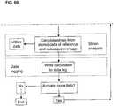
- FIGURES 6A and 6Bare for purposes of illustration, and some changes can be made in the algorithm without affecting the results.
- the display of the reference and subsequent imagescan take place sequentially with the analysis of those images, as well as substantially concurrently; the acquisition and display of the reference and/or the subsequent images can be initiated by an external event; and images can be recorded during an event and stored for processing at a later time.
- a sensoris used to collect a discrete or analog representation of the symbol's geometry.
- Sensor datais used to perform a deformation analysis on the symbol at two or more deformation states. This analysis mathematically describes the geometric deformation, and these results can be used to calculate strain.
Landscapes
- Physics & Mathematics (AREA)
- General Physics & Mathematics (AREA)
- Engineering & Computer Science (AREA)
- Theoretical Computer Science (AREA)
- Electromagnetism (AREA)
- Aviation & Aerospace Engineering (AREA)
- Artificial Intelligence (AREA)
- Computer Vision & Pattern Recognition (AREA)
- Investigating Strength Of Materials By Application Of Mechanical Stress (AREA)
- Length Measuring Devices By Optical Means (AREA)
Description
- The present invention relates to a binary code symbol for non-linear strain measurement. More specifically, the invention relates to a binary code symbol for non-linear strain measurement, which can encode a range of data values using an error-correcting code (ECC) technique, and a strain analysis and measurement method employing the binary code symbol.
- There are numerous one-dimensional (1D) and two-dimensional (2D) symbols in use today, and most utilize a majority of the symbol's surface area to store the encoded information. These symbols are typically comprised of large, distinguishable blocks, dots, or bars called "cells" that enable data encoding. The spacing, relative size, state (i.e. black or white), or some combination of cell attributes is exploited to encode and decode data. These types of symbols are designed for inexpensive, low-resolution reading devices (or sensors); therefore cell dimensions can be relatively large with respect to the overall symbol size.
- While many applications require that a symbol's encoded information be "read," there are additional applications that warrant a detailed accounting of the symbol's spatial characteristics. Metrology is one such application, which involves making precise geometric measurements of the symbol's features. Symbols optimized for "reading" purposes are not necessarily, nor are they normally, optimized for "metrology" purposes.
- Examples of common symbols (a UPC symbol, a Data Matrix symbol, and a MaxiCode symbol) are provided in
FIGURES 1A-1C . As shown inFIGURES 1A-1C , typical 1D and 2D symbols utilize cell arrangements that result in a broken (or non-continuous) symbol perimeter. Additionally, each has cells that are distributed somewhat uniformly across the entire symbol area. These characteristics are an efficient use of the symbol's surface area as a data encoder/decoder, but can cause a reduction in accuracy for certain types of deformation analyses, e.g. strain measurement. - Sensor resolution for machine-enabled metrology is typically higher than the sensor resolution required to simply encode and decode symbol information. Therefore with high-resolution sensors, it is possible to relax some of the "reader" requirements placed on existing symbol design, and produce symbols specifically for deformation/strain measurement.
US 6, 874, 370 describes a finite element analysis fatigue gage which is used for tracking nodes on the perimeter of a geometric shape for use in indirect strain measurements. This is used to determine fatigue damage in the body based on an equation and data obtained using strain-controlled test methods.US 6,000,614 describes a two-dimensional code reading apparatus using the image of a reference pattern of known shape in the two-dimensional code to compute areas, shapes and positions of cells in the image and correct these computed values using correction values obtained by identifying cells isolated from cells of the same type in at least one direction.- It is to the solution of these and other problems that the present invention is directed.
- It is accordingly a primary object of the present invention to provide a binary code symbol for non-linear strain measurement having a unique geometry and attributes.
- It is another object of the present invention to provide a binary code symbol for non-linear strain measurement having features that enhance deformation and strain measurement.
- It is still another object of the present invention to provide a binary code symbol for non-linear strain measurement that is designed specifically for perimeter-based deformation and strain analysis.
- It is still another object of the present invention to provide a perimeter strain analysis method for use with a binary code symbol for non-linear strain measurement.
- It is still another object of the present invention to provide a binary code symbol for non-linear strain measurement with near-perimeter data encoding.
- It is another object of the present invention to provide a binary code symbol for non-linear strain measurement that can encode a range of data values using an error-correcting code ("ECC") technique.
- These and other objects of the invention are achieved by the provision of a rectangular binary code symbol for non-linear strain measurement according to
Claim 1. In one aspect of the invention, the first and second utility regions of the binary code symbol can each have an inner half storing at least one of auxiliary information and codes. - In another aspect of the invention, the binary data represented by the data cells are encoded using an error-correcting code algorithm, for example, a Hamming 7-4 technique.
- A non-linear strain gage in accordance with the invention is provided according to Claim 7. In another aspect of the invention, the non-linear strain gage further comprises means for utilizing the strain measurement to provide information on at least one of fatigue damage and strain hysteresis for materials of known and unknown mechanical properties.
- In a method of measuring strain on an object directly, in accordance with the present invention, the binary code symbol is associated with an object in such a way that deformation of the binary code symbol and deformation under load of the object bear a one-to-one relationship, wherein the binary code symbol emits a detectable physical quantity. The changes in the binary code symbol are identified as a function of time and change in the load applied to the object. The changes in the binary code symbol are then into a direct measurement of strain.
- The binary code symbol in accordance with the present invention is based on monitoring the deformation of the geometry of the symbol based on using the fundamental concepts of non-linear stress analysis as developed by V.V. Novozhilov, Foundations of the Nonlinear Theory of Elasticity, Graylock Press, Rochester NY 1953.
- Other objects, features, and advantages of the present invention will be apparent to those skilled in the art upon a reading of this specification including the accompanying drawings.
- The invention is better understood by reading the following Detailed Description of the Preferred Embodiments with reference to the accompanying drawing figures, in which like reference numerals refer to like elements throughout, and in which:
FIGURE 1A illustrates a conventional UPC symbol.FIGURE 1B illustrates a conventional Data Matrix symbol.FIGURE 1C illustrates a conventional MaxiCode symbol.FIGURE 2 illustrates an exemplary layout of a rectangular binary code symbol in accordance with the present invention.FIGURE 3 illustrates an exemplary binary code symbol in accordance with the present invention with the number 27,097 encoded.FIGURE 4 illustrates the binary state of data cells in the first data region of the binary code symbol ofFIGURE 3 .FIGURE 6 shows the arrangement ofFIGURES 6A and6B .FIGURE 5 is a diagrammatic view of a non-linear strain gage in accordance with the present invention.FIGURES 6A and6B together are a high level flow diagram illustrating the algorithm followed by the computer program in accordance with the present invention.- In describing preferred embodiments of the present invention illustrated in the drawings, specific terminology is employed for the sake of clarity. However, the invention is not intended to be limited to the specific terminology so selected, and it is to be understood that each specific element includes all technical equivalents that operate in a similar manner to accomplish a similar purpose.
- A binary code symbol for non-linear strain measurement in accordance with the present invention is designed specifically for perimeter-based deformation and strain analysis, while providing for robust, self-checking/self-correcting data encoding. Specific geometric features of the symbol are optimized for perimeter-based, non-linear strain measurement using discrete or analog deformation analysis methods.
- The binary code symbol for non-linear strain measurement in accordance with the present invention is distinctly, materially, and theoretically different than the symbolic strain rosette ("SSR") as defined in
U.S. Patent Application No. 10/223,680, filed August 20, 2002 U.S. publication No. 2004-0036853 , inasmuch as the binary code symbol in accordance with the present invention is not based on utilizing a strain rosette and can measure non-linear strain, which the SSR cannot. - The binary code symbol in accordance with the present invention is rectangular in shape; has a solid, continuous outer perimeter, and enables data encoding near the symbol's perimeter. This unique combination of attributes significantly increases both the quantity and quality of distantly-spaced symbol features. These unique characteristics enable high-accuracy deformation analysis using discrete or analog techniques. Data is encoded in proportionately smaller regions of the symbol (compared to current symbols) therefore a higher resolution sensor is required to read and analyze the symbol.
- A typical layout of a rectangular symbol is shown in
FIGURE 2 . In the embodiment ofFIGURE 2 , therectangular symbol 10 is square in shape, with the characteristic solid, continuousouter perimeter 20. In the example shown inFIGURE 2 , thesymbol 10 also has a solid, continuous inner perimeter, although in general, a solid, continuous inner perimeter is not required. There are twodata regions 30 along adjacent sides of the rectangle. Eachdata region 30 is made up of a number ofdata cells 30a. Thesymbol 10 inFigure 2 has twenty-eightdata cells 30a perdata region 30; however no particular limit is placed on the number ofdata cells 30a perdata region 30. In the case of symbols that are symmetric about a diagonal of the rectangle, the data regions can be identical to one another for encoded-data redundancy. Opposite eachdata region 30 along a side of the rectangle is autility region 40.Utility regions 40 are made up ofutility cells Utility regions 40 assist in symbol location, orientation, and analysis. In addition, theinner half 40c of theutility regions 40 can be used to store auxiliary information and/or codes (e.g. vendor ID, application ID, function ID, version information, date/time, materials ID/info, etc.) There are twodistinct finder cells symbol 10. Inner and outerquiet regions data regions 30, theutility regions 40, and thefinder cells FIGURE 2 , broken lines are used to show the boundaries of the inner and outerquiet regions symbol 10 does not actually include these broken lines. - In a binary code symbol in accordance with the present invention, information is encoded via the symbol's data cells. An individual data cell represents a single bit of information; that is, its state is either "on" or "off" (i.e. "1" or "0"). The order and state of individual bit values combine to represent an encoded data value. The binary contribution of a single data cell is indicated by the cell's state, which is determined by a sensor. Data cells that have the same appearance as the symbol's background (or quiet region) are considered "on" or bit value "1." Data cells that have the same appearance as the foreground (or perimeter) are considered "off" or bit value "0."
- An example symbol is shown in
FIGURE 3 . This symbol has the data value 27,097 encoded in its data regions using an error-correction code (ECC) technique. The data value is encoded redundantly in the top and left data regions 30 (i.e. the two data regions are identical). In theFIGURE 3 example, the foreground is colored black, and the background is colored white. However, there are no restrictions placed on cell foreground and background appearance except that sufficient contrast is provided to enable a sensor to determine cell state. - Using the foreground and background appearance rules above, the binary state information in the
data cells 30 of the binary code symbol ofFIGURE 3 is illustrated inFIGURE 4 . The binary state of eachdata cell 30a, read left to right, is: 0,0,1,1,0,0,1,0,1,1,0,0,1,1,0,0,1,1,0,0,1,1,1,0,0,1,1,0. This string of zeros and ones can be converted to the decimal number 27,097 using a reverse application of the Hamming 7-4 technique (i.e. decoding), as discussed in greater detail hereinafter. - It is desirable that encoded data be somewhat "self correcting" in the event that part of the symbol is damaged, scratched, or otherwise degraded. Therefore, the binary data in each data region of the symbol is encoded using an error-correcting code (ECC) algorithm. The ECC algorithm combines vector-space mathematics and set theory to convert numeric quantities into encoded values that provide limited self-checking and self-correcting capability during decoding. The use of ECC algorithms plus data redundancy provides for robust encoding and limited protection against data loss.
- Using redundancy and ECC methods, the symbol in
FIGURE 3 , with 28 data cells per data region, can encode any data value in the range 0 to 65,535. If redundancy were not used, the data capacity of the symbol inFIGURE 3 would increase to over 4-billion possible data values. - The ECC algorithm used is a Hamming 7-4 technique. This encoding method takes the original data value (un-encoded) and breaks it into 4-bit "words." Each 4-bit word is encoded into a 7-bit word containing the original value and three "check bits." This method permits the original 4-bit word to be recovered in the event that the sensor cannot determine the state of one of the 7-bit word's bits. Therefore, the original data value can be recovered if up to one bit in each word is lost.
- The Hamming technique used has an encoding "efficiency" of 0.571. This is calculated as the ratio of the number of original bits (N1) to the number of encoded bits (N2). For the example in
Figure 3 ,N1 = 16 andN2 = 28, giving:
- Therefore the data capacity (or number of unique combinations of data values) for a single data region in a symbol that uses ECC encoding, expressed in terms of the number of data cells per region (N2) is roughly:

- The symbol is specifically designed to enable high-accuracy deformation analysis. The symbol's solid perimeter and perimeter-encoding technique are unique attributes that significantly increase both the quantity and quality of distantly-spaced symbol features. These qualities improve the accuracy of deformation analyses using discrete or analog machine-enabled techniques.
- Deformation analysis can provide a detailed accounting of the symbol's spatial characteristics under various conditions. For instance, deformation analysis can mathematically describe geometric changes from some reference state to some subsequent state (e.g. a change in size, shape, symmetry, etc.).
- Strain measurement is one useful product of deformation analysis. Strain is a unitless mechanical property defined as a change in length per unit length.
- Referring now to
FIGURE 5 , there is shown diagrammatically anon-linear strain gage 100 for measuring the strain on an object under load in accordance with the present invention, comprising atarget 110, asensor 120, and acomputer 130, wherein thetarget 110 is a binary code symbol in accordance with the present invention, which has been manufactured or identified. The binary code symbol can be composed of a plurality of sub-images, each of which has a centroid, and can be monitored by thesensor 120 to correlate the movement of sub-image centroids associated with rectangular elements formed in thedata regions 30 of the binary code symbol. - The
target 110 can be associated with an object by any means that results in the deformation of the binary code symbol with the deformation under load. The deformation of the binary code symbol and the object must bear a one-to-one relationship. Thetarget 110 can be associated with an object for which strain is to be measured by applying it directly or indirectly to the surface of the object, or by identifying it in a pre-existing pattern that defines a binary code symbol. Whether applied or identified, thetarget 110 can be embedded in the object for which strain is to be measured. - Examples of application of a
target 110 include, but are not limited to: - (1) Application to a medium such as a polymide film that is bonded, for example by gluing, to the surface of the object for which strain is to be measured (indirect application);
- (2) Etching on a surface (direct application);
- (3) Painting on surface (direct application); and
- (4) Printing on a surface (direct application).
- Target applications are described in detail in NASA STD 6002 and Handbook 6003.
- Examples of identification of a
target 110 include, but are not limited to: - (1) Identification by observing naturally-occurring surface features of the object that define a binary code symbol on a macroscopic or microscopic scale (including as an example, but not limited to, features on the surface of the earth).
- (2) Identification by observing naturally-occurring subsurface features of the object that define a binary code symbol on a macroscopic or microscopic scale (including as an example, but not limited to, a fossil buried in the earth).
- (3) Identification by observing manmade surface features of the object that define a binary code symbol on a macroscopic or microscopic scale (including as an example, but not limited to, a collection of components).
- (4) Identification by observing manmade subsurface features of the object that define an binary code symbol on a macroscopic or microscopic scale (including as examples, but not limited to, structural elements of a spacecraft covered with a skin, the structural elements of a bridge covered with a skin, or the structural elements of a building having a surface opaque in the visible spectrum).
- Examples of embedding of a
target 110 include, but are not limited to: - (1) Embedding in the object to be studied when the object is being formed;
- (2) Identification of naturally occurring or manufactured subsurface features;
- (3) Covering with an overlying material, such as one or more layers of paint; and
- (4) Implanting in a human body, in a body part or an implant. For example, if the
target 110 is affixed to a critical area of a hip joint or a hip implant, or to an artificial heart valve, thetarget 110 can be viewed through the tissue surrounding thetarget 110 by anx-ray sensor 120, and the strain and fatigue damage to the associated body part or implant can be assessed over time. - The
target 110 can naturally emit a detectable physical quantity, create a detectable physical quantity, or reflect a detectable physical quantity. The detectable physical quantity can be a signal in any portion of the electromagnetic spectrum (including the audio frequency range), or it can be a field such as a magnetic field. The detectable physical quantity can be a signal that can be characterized as a grayscale image that can be converted into a bitmap file. Sensors that will sense various detectable physical quantities, including all these signals and fields, are commercially available. - The
target 110 is scalable, in that it can be produced and sensed on a scale ranging from microscopic to macroscopic. Thus, thenon-linear strain gage 100 in accordance with the present invention is applicable to very large applications such as viewing atarget 110 on earth from space to determine displacements/strain of the earth's surface or subsurface strains. All that is required is to match thesensor 120 to the scale or scope of the target and the detectable physical quantity emitted by thetarget 110. - One advantage of the
non-linear strain gage 100 is that strain is measured directly, as opposed to being inferred from secondary measurements using analog techniques; thus making possible an explicit detectable "reading" of normal and shear strain components. This in turn leads to greater accuracy and reduced system errors. - Another advantage of the
non-linear strain gage 100 is that the range of strain measurements is easily from 0 to at least 50%, which permits measurements of strain in elastic materials such as rubber and plastic. The potential exits to cover measurements at the nanoscale level. - A third, and major advantage of the
non-linear strain gage 100 is that subsurface strains can be measured. Subsurface measurements can have special applications in man-made composites. - The
non-linear strain gage 100 also can be used in the assessment of fatigue damage (accumulation) in critical areas of structures or components of devices subjected to cyclic or other loadings. This is accomplished by observing the area of a component under study over a selected period of time during the normal usage of the area. The data can then be used to assist in component lifecycle management. - The
sensor 120 observes the deformation of atarget 110 affixed to a surface or embedded in a material by capturing the total image of thetarget 110 and transmitting it to thecomputer 130. Thesensor 120 is selected to be compatible with the detectable physical quantity emitted by thetarget 110 and undertakes some pre-processing of the observed physical quantity to provide data representing the physical quantity to thecomputer 130. In the case of a binary code symbol that can be monitored optically, the input signal to thesensor 120 may be a grayscale image that can be converted into a bitmap file, although other inputs can be accommodated. - The
computer 130 conventionally comprisesmemory 130a for storing programs and data and aprocessor 130b for implementing the programs and processing the data, and is associated with adisplay 130c for displaying data. As the object under study is submitted to loading resulting in strain, thecomputer 130 implements programs that (1) identify the binary code symbol and the changes therein as a function of time and change in the load, (2) translate the changes in the binary code symbol into strain, and (3) display it in a suitable format. The display of the data can take place in real time. The technology is scalable with respect to the size of the object under study. - The binary code symbol is monitored -- by optical, magnetic, electromagnetic, acoustic, or
other sensor 120, as appropriate -- at successive periods of time, either on a continuous time, at random times triggered by an external event, or on a programmed time basis. The sub-images of the binary code symbol are correlated over time to detect the movement of the centroids of the sub-images, and the movements are quantified and utilized in analytical expressions to determine strain in the directions of the coordinate system used corresponding to the plane of the surface under study. The movement of the centroids is detected by a program implemented by thecomputer 130 in accordance with the present invention, which identifies the binary code symbol and its sub-images, correlates the sub-images of the binary code symbol over time, determines the displacement of the centroids of the sub-images of the binary code symbol, and utilizes the data obtained as input for strain equations as described hereinafter and to yield and display strain in two dimensions. - Referring now to
FIGURES 6A and6B together, there are shown a high level flow diagram illustrating the algorithm followed by the computer programs in accordance with the present invention. The algorithm comprises three basic stages, image grabbing, strain analysis, and data logging; and utilizes two types of images, a reference image, acquired either without application of a load or with a reference load on the object for which strain is to be measured, and subsequent images, acquired after the reference image in the presence of a load or change to the load on the object. - The image grabbing stage comprises the following steps: The
sensor 120 acquires the reference image and outputs data representing the reference image to thecomputer 130. A program or programs implemented by thecomputer 130 then analyzes the reference image data to define an binary code symbol, and concurrently displays the reference image, preferably in real time, on a computer monitor orother display device 130c. Following the analysis step, thecomputer 130 stores the analyzed reference image data. Once the reference image has been acquired, analyzed, and stored, thesensor 120 acquires a subsequent image and outputs data representing that subsequent image (that is, the current subsequent image) to thecomputer 130. - Acquisition of subsequent images can take place either continuously or at predetermined intervals, or it can be triggered by an external event such as the application of a load. The number of subsequent images thus can range from one to thousands. Once data representing a subsequent image is input to the
computer 130, the program analyzes it to define a binary code symbol, and concurrently displays the corresponding subsequent image, preferably in real time, on a computer monitor or other display device (preferably on the same monitor orother display device 130c on which the reference image is being displayed, to facilitate comparison). Following the analysis step, thecomputer 130 stores the analyzed subsequent image data for the current subsequent image. - The strain analysis stage takes place following the image grabbing stage, and is carried out each time a subsequent image is acquired. In the strain analysis stage, the
computer 130 calculates the strain from the stored reference image data and the stored subsequent image data for the current subsequent image, based on the changes in the binary code symbol as a function of time and change in the load. Thus, a new strain calculation is made for each subsequent image. The strain calculation can then be utilized as a display, as well as providing information on fatigue damage or strain hysteresis for materials of known and unknown mechanical properties, and data that can be used to assist in component lifecycle management. - The data logging stage takes place following each iteration of the strain analysis stage. In the data logging stage, the program gets the current results and writes them to a log file.
- As will be appreciated by those of skill in the art, the flow diagram of
FIGURES 6A and6B is for purposes of illustration, and some changes can be made in the algorithm without affecting the results. For example, the display of the reference and subsequent images can take place sequentially with the analysis of those images, as well as substantially concurrently; the acquisition and display of the reference and/or the subsequent images can be initiated by an external event; and images can be recorded during an event and stored for processing at a later time. - To measure strain using the symbol, a sensor is used to collect a discrete or analog representation of the symbol's geometry. Sensor data is used to perform a deformation analysis on the symbol at two or more deformation states. This analysis mathematically describes the geometric deformation, and these results can be used to calculate strain.
- It is to be understood that various types and styles of user interfaces may be used in accordance with the present invention. Modifications and variations of the above-described embodiments of the present invention are possible, as appreciated by those skilled in the art in light of the above teachings.


Claims (18)
- A rectangular binary code symbol (10) for non-linear strain measurement, comprising:a rectangular outer perimeter(20);first and second data regions (30) along adjacent sides of the outer perimeter, each data region comprising a number of data cells (30a), each data cell representing a single bit of binary data,;first and second utility regions (40) along adjacent sides of the outer perimeter and on opposite sides of the outer perimeter from the first and second data regions, each utility region comprising a number of utility cells (40a, 40b)of alternating appearance,;first and second finder cells (50a, 50b) at opposite corners of the outer perimeter; andan outer quiet region (60b) distinguishing the first and second data regions, the first and second utility regions, and the first and second finder cells from their background, the outer quiet region being outward of the outer perimeter;characterized in that:the outer perimeter is solid and continuous;the rectangular binary code symbol further comprises an inner perimeter; andan inner quiet region (60a) is provided, distinguishing the first and second data regions, the first and second utility regions, and the first and second finder cells from their background, the inner quiet region being inward of the inner perimeter.
- The binary code symbol of claim 1, wherein the first and second utility regions each have an inner half storing at least one of auxiliary information and codes.
- The binary code symbol of claim 1, wherein the symbol is symmetric and the first and second data regions are identical to one another for encoded-data redundancy.
- The binary code symbol of claim 1, wherein the binary data represented by the data cells are encoded using an error-correcting code algorithm.
- The binary code symbol of claim 4, wherein the error-correcting code algorithm combines vector-space mathematics and set theory to convert numeric quantities into encoded values that provide limited self-checking and self-correcting capability during decoding.
- The binary code symbol of claim 5, wherein the algorithm used is a Hamming 7-4 technique.
- A non-linear strain gage comprising:a target (110) associated with an object for which at least one of strain and fatigue damage is to be measured and emitting a detectable physical quantity, the target comprising a binary code symbol; sensor means (120) for pre-processing the detectable physical quantity emitted by the binary code symbol and outputting data representing the physical quantity, the sensor means being compatible with the detectable physical quantity;means for analyzing the data (130) output by the sensor means to define the binary code symbol; andmeans for measuring the strain on the object based on the pre-processed and analyzed data;characterized in that:the binary code symbol is the binary code symbol according to claim 1; andthe means for measuring the strain measures the strain on the object directly.
- The non-linear strain gage of claim 7, further comprising means for utilizing the strain measurement to provide information on at least one of fatigue damage and strain hysteresis for materials of known and unknown mechanical properties.
- The non-linear strain gage of claim 7, further comprising means for utilizing the strain measurement to assist in component lifecycle management.
- The non-linear strain gage of claim 7, further comprising means for utilizing the strain measurement based on collected damage accumulation data.
- The non-linear strain gage of claim 7, wherein the binary code symbol is defineda priori by manufacture.
- The non-linear strain gage of claim 7, wherein the target is identified in a pre-existing pattern that defines the binary code symbol.
- A method of measuring strain on an object directly, comprising the steps of:associating the binary code symbol according to claim 1 with an object in such a way that deformation of the binary code symbol and deformation under load of the object bear a one-to-one relationship, wherein the binary code symbol emits a detectable physical quantity;identifying the changes in the binary code symbol as a function of time and change in the load applied to the object; andtranslating the changes in the binary code symbol into a measurement of strain;characterized in that:in the translating step, the measurement of strain is a direct measurement.
- The method of claim 13, wherein the binary code symbol is defineda priori by manufacture and the associating step comprises applying the binary code symbol to the object.
- The method of claim 13, wherein the associating step comprises identifying the binary code symbola priori.
- The method of claim 13, further comprising the step of utilizing the strain measurement to provide information on at least one of fatigue damage and strain hysteresis for materials of known and unknown mechanical properties.
- The method of claim 13, further comprising the step of utilizing the strain measurement to assist in component lifecycle management.
- The method of claim 13, further comprising the step of utilizing the strain measurement based on collected damage accumulation data.
Priority Applications (1)
| Application Number | Priority Date | Filing Date | Title |
|---|---|---|---|
| PL05849759TPL1897036T3 (en) | 2005-06-28 | 2005-11-17 | Binary code symbol for non-linear strain measurement and method and apparatus for analyzing and measuring same |
Applications Claiming Priority (2)
| Application Number | Priority Date | Filing Date | Title |
|---|---|---|---|
| US11/167,558US7533818B2 (en) | 2005-06-28 | 2005-06-28 | Binary code symbol for non-linear strain measurement and apparatus and method for analyzing and measuring strain therewith |
| PCT/US2005/041516WO2007001460A2 (en) | 2005-06-28 | 2005-11-17 | Binary code symbol and method and apparatus for analyzing and measuring same |
Publications (3)
| Publication Number | Publication Date |
|---|---|
| EP1897036A2 EP1897036A2 (en) | 2008-03-12 |
| EP1897036A4 EP1897036A4 (en) | 2012-11-14 |
| EP1897036B1true EP1897036B1 (en) | 2017-09-27 |
Family
ID=37566171
Family Applications (1)
| Application Number | Title | Priority Date | Filing Date |
|---|---|---|---|
| EP05849759.5AActiveEP1897036B1 (en) | 2005-06-28 | 2005-11-17 | Binary code symbol for non-linear strain measurement and method and apparatus for analyzing and measuring same |
Country Status (6)
| Country | Link |
|---|---|
| US (1) | US7533818B2 (en) |
| EP (1) | EP1897036B1 (en) |
| KR (1) | KR101143261B1 (en) |
| CA (1) | CA2612713C (en) |
| PL (1) | PL1897036T3 (en) |
| WO (1) | WO2007001460A2 (en) |
Families Citing this family (34)
| Publication number | Priority date | Publication date | Assignee | Title |
|---|---|---|---|---|
| US7377181B2 (en)* | 2006-03-10 | 2008-05-27 | Northrop Grumman Corporation | In-situ large area optical strain measurement using an encoded dot pattern |
| US8459567B2 (en)* | 2006-08-17 | 2013-06-11 | Direct Measurements, Inc. | Non-linear strain gage incorporating a nested binary code symbol |
| US20090326836A1 (en)* | 2006-08-17 | 2009-12-31 | Gregory L Hovis | Two dimensional bar code having increased accuracy |
| EP2126712A4 (en)* | 2007-02-23 | 2014-06-04 | Direct Measurements Inc | Differential non-linear strain measurement using binary code symbol |
| US20110106459A1 (en)* | 2009-10-29 | 2011-05-05 | Northrop Grumman Corporation | In-situ optical crack measurement using a dot pattern |
| US8581736B2 (en) | 2010-06-24 | 2013-11-12 | The Boeing Company | Assessing structural repair integrity |
| US20140267677A1 (en)* | 2013-03-14 | 2014-09-18 | General Electric Company | Turbomachine component monitoring system and method |
| CN103927573B (en)* | 2014-04-14 | 2016-08-24 | 立德高科(北京)数码科技有限责任公司 | Under visible ray, uniqueness serial number and dot pattern carry out the method and device bound |
| JP6491931B2 (en)* | 2015-04-03 | 2019-03-27 | 株式会社Nttドコモ | Information processing apparatus and program |
| US10697760B2 (en) | 2015-04-15 | 2020-06-30 | General Electric Company | Data acquisition devices, systems and method for analyzing strain sensors and monitoring component strain |
| US9618334B2 (en) | 2015-04-15 | 2017-04-11 | General Electric Company | Systems and methods for monitoring turbine component strain |
| US9909860B2 (en) | 2015-04-15 | 2018-03-06 | General Electric Company | Systems and methods for monitoring component deformation |
| US9557164B2 (en) | 2015-04-15 | 2017-01-31 | General Electric Company | Data acquisition devices, systems and method for analyzing strain sensors and monitoring turbine component strain |
| US9932853B2 (en) | 2015-04-28 | 2018-04-03 | General Electric Company | Assemblies and methods for monitoring turbine component strain |
| US9953408B2 (en) | 2015-11-16 | 2018-04-24 | General Electric Company | Methods for monitoring components |
| US9846933B2 (en) | 2015-11-16 | 2017-12-19 | General Electric Company | Systems and methods for monitoring components |
| US9733062B2 (en) | 2015-11-20 | 2017-08-15 | General Electric Company | Systems and methods for monitoring component strain |
| US10012552B2 (en) | 2015-11-23 | 2018-07-03 | General Electric Company | Systems and methods for monitoring component strain |
| US9967523B2 (en) | 2015-12-16 | 2018-05-08 | General Electric Company | Locating systems and methods for components |
| US10557372B2 (en)* | 2015-12-17 | 2020-02-11 | General Electric Company | Systems and methods for assessing strain of components in turbomachines |
| US20170176269A1 (en)* | 2015-12-17 | 2017-06-22 | General Electric Company | Components with array-based strain sensors and methods for monitoring the same |
| US10030534B2 (en)* | 2016-02-24 | 2018-07-24 | General Electric Company | Detectable datum markers for gas turbine engine components for measuring distortion |
| US20180038779A1 (en)* | 2016-08-05 | 2018-02-08 | General Electric Company | Embedded strain sensor network |
| US9879981B1 (en) | 2016-12-02 | 2018-01-30 | General Electric Company | Systems and methods for evaluating component strain |
| US10132615B2 (en) | 2016-12-20 | 2018-11-20 | General Electric Company | Data acquisition devices, systems and method for analyzing passive strain indicators and monitoring turbine component strain |
| US10126119B2 (en) | 2017-01-17 | 2018-11-13 | General Electric Company | Methods of forming a passive strain indicator on a preexisting component |
| US10872176B2 (en) | 2017-01-23 | 2020-12-22 | General Electric Company | Methods of making and monitoring a component with an integral strain indicator |
| US11313673B2 (en) | 2017-01-24 | 2022-04-26 | General Electric Company | Methods of making a component with an integral strain indicator |
| US10345179B2 (en)* | 2017-02-14 | 2019-07-09 | General Electric Company | Passive strain indicator |
| US10502551B2 (en) | 2017-03-06 | 2019-12-10 | General Electric Company | Methods for monitoring components using micro and macro three-dimensional analysis |
| US10451499B2 (en) | 2017-04-06 | 2019-10-22 | General Electric Company | Methods for applying passive strain indicators to components |
| US10228237B2 (en)* | 2017-07-12 | 2019-03-12 | The Boeing Company | Non-destructive optical method for determining minimum bond strength and proving bond efficacy |
| JP7009630B2 (en)* | 2019-12-13 | 2022-01-25 | 三菱電機株式会社 | Inspection device for rotary electric machine, rotary electric machine, and inspection method for rotary electric machine |
| DE102023135120B4 (en) | 2023-12-14 | 2025-09-11 | Hochschule Kaiserslautern, Körperschaft des öffentlichen Rechts | Connection system |
Family Cites Families (36)
| Publication number | Priority date | Publication date | Assignee | Title |
|---|---|---|---|---|
| US3474237A (en) | 1966-10-03 | 1969-10-21 | Automation Ind Inc | Strain gage rosette calculator |
| US4008960A (en) | 1975-08-18 | 1977-02-22 | Reytblatt Zinovy V | Photoelastic strain gauge coating and method of using same |
| US4050818A (en) | 1975-09-10 | 1977-09-27 | The United States Of America As Represented By The Secretary Of The Air Force | Method for determining changes in spacing between two positions of interest |
| US4014613A (en) | 1975-09-10 | 1977-03-29 | The United States Of America As Represented By The Secretary Of The Air Force | Method and apparatus for determining changes in spacing between two positions of interest |
| US4288852A (en) | 1979-11-28 | 1981-09-08 | General Motors Corporation | Method and apparatus for automatically determining sheet metal strain |
| JPS57125803A (en) | 1981-01-29 | 1982-08-05 | Toyoda Gosei Co Ltd | Method for measuring strain of sample surface |
| US5065331A (en) | 1981-05-18 | 1991-11-12 | Vachon Reginald I | Apparatus and method for determining the stress and strain in pipes, pressure vessels, structural members and other deformable bodies |
| US4591996A (en) | 1981-05-18 | 1986-05-27 | Vachon Reginald I | Apparatus and method for determining stress and strain in pipes, pressure vessels, structural members and other deformable bodies |
| US4722600A (en) | 1986-10-14 | 1988-02-02 | Chiang Fu Pen | Apparatus and method for measuring strain |
| US5053609A (en) | 1988-05-05 | 1991-10-01 | International Data Matrix, Inc. | Dynamically variable machine readable binary code and method for reading and producing thereof |
| US4939354A (en) | 1988-05-05 | 1990-07-03 | Datacode International, Inc. | Dynamically variable machine readable binary code and method for reading and producing thereof |
| US5124536A (en) | 1988-05-05 | 1992-06-23 | International Data Matrix, Inc. | Dynamically variable machine readable binary code and method for reading and producing thereof |
| US5047952A (en) | 1988-10-14 | 1991-09-10 | The Board Of Trustee Of The Leland Stanford Junior University | Communication system for deaf, deaf-blind, or non-vocal individuals using instrumented glove |
| US4969106A (en) | 1989-02-27 | 1990-11-06 | Camsys, Inc. | Computerized method of determining surface strain distributions in a deformed body |
| US5671042A (en) | 1992-02-18 | 1997-09-23 | Illinois Institute Of Technology | Holomoire strain analyzer |
| EP0651352A1 (en) | 1993-10-27 | 1995-05-03 | Toshiba Engineering Corporation | Method and apparatus of inspecting surface irregularity of an object article |
| US5531122A (en) | 1994-02-28 | 1996-07-02 | Caterpillar Inc. | Fatigue analysis and warning system |
| US5726435A (en)* | 1994-03-14 | 1998-03-10 | Nippondenso Co., Ltd. | Optically readable two-dimensional code and method and apparatus using the same |
| GB2296120A (en)* | 1994-12-13 | 1996-06-19 | Ibm | Barcode decoding |
| JP2867904B2 (en)* | 1994-12-26 | 1999-03-10 | 株式会社デンソー | 2D code reader |
| US5726907A (en) | 1995-07-31 | 1998-03-10 | Southwest Research Institute | Biaxial non-contacting strain measurement using machine vision |
| US6000614A (en)* | 1996-12-20 | 1999-12-14 | Denso Corporation | Two-dimensional code reading apparatus |
| JPH10326331A (en)* | 1997-03-24 | 1998-12-08 | Olympus Optical Co Ltd | Recording medium with dot code, and code reader |
| US5920383A (en) | 1997-12-05 | 1999-07-06 | Ford Global Technologies, Inc. | Microscopic digital imaging strain gauge |
| US6189386B1 (en) | 1997-12-05 | 2001-02-20 | Ford Global Technologies, Inc. | Method of using a microscopic digital imaging strain gauge |
| US6028889A (en)* | 1998-02-25 | 2000-02-22 | Lucent Technologies, Inc. | Pipelined fast hadamard transform |
| US6267296B1 (en)* | 1998-05-12 | 2001-07-31 | Denso Corporation | Two-dimensional code and method of optically reading the same |
| US6189356B1 (en) | 2000-02-17 | 2001-02-20 | General Electric Company | Method and apparatus for peening |
| DE10036836A1 (en)* | 2000-07-28 | 2002-02-07 | Runge Hans Juergen | Pressure difference sensor for refilling aircraft fuel tanks uses optical coding to give continuous read out |
| JP2002267422A (en) | 2001-03-09 | 2002-09-18 | Nippon Koei Power Systems Co Ltd | Crack detection method and device |
| DE10124839A1 (en)* | 2001-05-16 | 2002-11-21 | Yuichiro M E Honda | Control of a prosthesis attached to a limb such as an upper arm or leg in which electrical detection of muscle impulses is replaced by optical detection of deformation of a code object placed on the limb surface |
| US6718269B2 (en) | 2001-12-13 | 2004-04-06 | International Business Machines Corporation | Apparatus, program product and method of estimating the stress intensity factor ratio of a material |
| JP4301775B2 (en)* | 2002-07-18 | 2009-07-22 | シャープ株式会社 | Two-dimensional code reading device, two-dimensional code reading method, two-dimensional code reading program, and recording medium for the program |
| US7451292B2 (en)* | 2002-08-10 | 2008-11-11 | Thomas J Routt | Methods for transmitting data across quantum interfaces and quantum gates using same |
| US6934013B2 (en)* | 2002-08-20 | 2005-08-23 | Reginald Vachon | Compressed symbology strain gage |
| US6874370B1 (en) | 2004-07-15 | 2005-04-05 | Reginald I. Vachon | Finite element analysis fatigue gage |
- 2005
- 2005-06-28USUS11/167,558patent/US7533818B2/enactiveActive
- 2005-11-17CACA2612713Apatent/CA2612713C/enactiveActive
- 2005-11-17PLPL05849759Tpatent/PL1897036T3/enunknown
- 2005-11-17WOPCT/US2005/041516patent/WO2007001460A2/enactiveSearch and Examination
- 2005-11-17EPEP05849759.5Apatent/EP1897036B1/enactiveActive
- 2005-11-17KRKR1020087002326Apatent/KR101143261B1/ennot_activeExpired - Fee Related
Non-Patent Citations (1)
| Title |
|---|
| None* |
Also Published As
| Publication number | Publication date |
|---|---|
| PL1897036T3 (en) | 2018-03-30 |
| KR20080041187A (en) | 2008-05-09 |
| US7533818B2 (en) | 2009-05-19 |
| CA2612713A1 (en) | 2007-01-04 |
| WO2007001460A3 (en) | 2007-11-08 |
| EP1897036A2 (en) | 2008-03-12 |
| KR101143261B1 (en) | 2012-05-11 |
| WO2007001460A2 (en) | 2007-01-04 |
| EP1897036A4 (en) | 2012-11-14 |
| CA2612713C (en) | 2013-12-24 |
| US20060289652A1 (en) | 2006-12-28 |
Similar Documents
| Publication | Publication Date | Title |
|---|---|---|
| EP1897036B1 (en) | Binary code symbol for non-linear strain measurement and method and apparatus for analyzing and measuring same | |
| US7477995B2 (en) | Optical linear strain gage | |
| US7878415B2 (en) | Segmented circular bar code | |
| US6934013B2 (en) | Compressed symbology strain gage | |
| CA2696850C (en) | High density, rectangular binary code symbol | |
| US8459567B2 (en) | Non-linear strain gage incorporating a nested binary code symbol | |
| US8245578B2 (en) | Differential non-linear strain measurement using binary code symbol | |
| US6874370B1 (en) | Finite element analysis fatigue gage | |
| EP4028742B1 (en) | Apparatus for measuring soil contact stresses | |
| MX2008000182A (en) | Binary code symbol and method and apparatus for analyzing and measuring same | |
| HK1078928B (en) | Compressed symbology strain gauge | |
| HK1104085B (en) | Finite element analysis fatigue gage |
Legal Events
| Date | Code | Title | Description |
|---|---|---|---|
| PUAI | Public reference made under article 153(3) epc to a published international application that has entered the european phase | Free format text:ORIGINAL CODE: 0009012 | |
| 17P | Request for examination filed | Effective date:20080108 | |
| AK | Designated contracting states | Kind code of ref document:A2 Designated state(s):AT BE BG CH CY CZ DE DK EE ES FI FR GB GR HU IE IS IT LI LT LU LV MC NL PL PT RO SE SI SK TR | |
| AX | Request for extension of the european patent | Extension state:AL BA HR MK YU | |
| A4 | Supplementary search report drawn up and despatched | Effective date:20121017 | |
| RIC1 | Information provided on ipc code assigned before grant | Ipc:G01B 11/16 20060101ALI20121011BHEP Ipc:G01M 5/00 20060101ALI20121011BHEP Ipc:G06K 19/06 20060101AFI20121011BHEP Ipc:G01L 5/00 20060101ALI20121011BHEP | |
| RAP1 | Party data changed (applicant data changed or rights of an application transferred) | Owner name:GENERAL ELECTRIC COMPANY | |
| GRAP | Despatch of communication of intention to grant a patent | Free format text:ORIGINAL CODE: EPIDOSNIGR1 | |
| INTG | Intention to grant announced | Effective date:20170503 | |
| GRAS | Grant fee paid | Free format text:ORIGINAL CODE: EPIDOSNIGR3 | |
| GRAA | (expected) grant | Free format text:ORIGINAL CODE: 0009210 | |
| AK | Designated contracting states | Kind code of ref document:B1 Designated state(s):AT BE BG CH CY CZ DE DK EE ES FI FR GB GR HU IE IS IT LI LT LU LV MC NL PL PT RO SE SI SK TR | |
| AX | Request for extension of the european patent | Extension state:AL BA HR MK YU | |
| REG | Reference to a national code | Ref country code:GB Ref legal event code:FG4D | |
| REG | Reference to a national code | Ref country code:CH Ref legal event code:EP | |
| REG | Reference to a national code | Ref country code:AT Ref legal event code:REF Ref document number:932626 Country of ref document:AT Kind code of ref document:T Effective date:20171015 | |
| REG | Reference to a national code | Ref country code:IE Ref legal event code:FG4D | |
| REG | Reference to a national code | Ref country code:DE Ref legal event code:R096 Ref document number:602005052819 Country of ref document:DE | |
| PG25 | Lapsed in a contracting state [announced via postgrant information from national office to epo] | Ref country code:FI Free format text:LAPSE BECAUSE OF FAILURE TO SUBMIT A TRANSLATION OF THE DESCRIPTION OR TO PAY THE FEE WITHIN THE PRESCRIBED TIME-LIMIT Effective date:20170927 Ref country code:LT Free format text:LAPSE BECAUSE OF FAILURE TO SUBMIT A TRANSLATION OF THE DESCRIPTION OR TO PAY THE FEE WITHIN THE PRESCRIBED TIME-LIMIT Effective date:20170927 Ref country code:SE Free format text:LAPSE BECAUSE OF FAILURE TO SUBMIT A TRANSLATION OF THE DESCRIPTION OR TO PAY THE FEE WITHIN THE PRESCRIBED TIME-LIMIT Effective date:20170927 | |
| REG | Reference to a national code | Ref country code:NL Ref legal event code:MP Effective date:20170927 | |
| REG | Reference to a national code | Ref country code:LT Ref legal event code:MG4D | |
| REG | Reference to a national code | Ref country code:AT Ref legal event code:MK05 Ref document number:932626 Country of ref document:AT Kind code of ref document:T Effective date:20170927 | |
| PG25 | Lapsed in a contracting state [announced via postgrant information from national office to epo] | Ref country code:GR Free format text:LAPSE BECAUSE OF FAILURE TO SUBMIT A TRANSLATION OF THE DESCRIPTION OR TO PAY THE FEE WITHIN THE PRESCRIBED TIME-LIMIT Effective date:20171228 Ref country code:LV Free format text:LAPSE BECAUSE OF FAILURE TO SUBMIT A TRANSLATION OF THE DESCRIPTION OR TO PAY THE FEE WITHIN THE PRESCRIBED TIME-LIMIT Effective date:20170927 Ref country code:BG Free format text:LAPSE BECAUSE OF FAILURE TO SUBMIT A TRANSLATION OF THE DESCRIPTION OR TO PAY THE FEE WITHIN THE PRESCRIBED TIME-LIMIT Effective date:20171227 | |
| PG25 | Lapsed in a contracting state [announced via postgrant information from national office to epo] | Ref country code:NL Free format text:LAPSE BECAUSE OF FAILURE TO SUBMIT A TRANSLATION OF THE DESCRIPTION OR TO PAY THE FEE WITHIN THE PRESCRIBED TIME-LIMIT Effective date:20170927 | |
| PG25 | Lapsed in a contracting state [announced via postgrant information from national office to epo] | Ref country code:RO Free format text:LAPSE BECAUSE OF FAILURE TO SUBMIT A TRANSLATION OF THE DESCRIPTION OR TO PAY THE FEE WITHIN THE PRESCRIBED TIME-LIMIT Effective date:20170927 Ref country code:ES Free format text:LAPSE BECAUSE OF FAILURE TO SUBMIT A TRANSLATION OF THE DESCRIPTION OR TO PAY THE FEE WITHIN THE PRESCRIBED TIME-LIMIT Effective date:20170927 | |
| PG25 | Lapsed in a contracting state [announced via postgrant information from national office to epo] | Ref country code:SK Free format text:LAPSE BECAUSE OF FAILURE TO SUBMIT A TRANSLATION OF THE DESCRIPTION OR TO PAY THE FEE WITHIN THE PRESCRIBED TIME-LIMIT Effective date:20170927 Ref country code:AT Free format text:LAPSE BECAUSE OF FAILURE TO SUBMIT A TRANSLATION OF THE DESCRIPTION OR TO PAY THE FEE WITHIN THE PRESCRIBED TIME-LIMIT Effective date:20170927 Ref country code:IS Free format text:LAPSE BECAUSE OF FAILURE TO SUBMIT A TRANSLATION OF THE DESCRIPTION OR TO PAY THE FEE WITHIN THE PRESCRIBED TIME-LIMIT Effective date:20180127 Ref country code:EE Free format text:LAPSE BECAUSE OF FAILURE TO SUBMIT A TRANSLATION OF THE DESCRIPTION OR TO PAY THE FEE WITHIN THE PRESCRIBED TIME-LIMIT Effective date:20170927 | |
| REG | Reference to a national code | Ref country code:DE Ref legal event code:R097 Ref document number:602005052819 Country of ref document:DE | |
| PG25 | Lapsed in a contracting state [announced via postgrant information from national office to epo] | Ref country code:MC Free format text:LAPSE BECAUSE OF FAILURE TO SUBMIT A TRANSLATION OF THE DESCRIPTION OR TO PAY THE FEE WITHIN THE PRESCRIBED TIME-LIMIT Effective date:20170927 | |
| PG25 | Lapsed in a contracting state [announced via postgrant information from national office to epo] | Ref country code:DK Free format text:LAPSE BECAUSE OF FAILURE TO SUBMIT A TRANSLATION OF THE DESCRIPTION OR TO PAY THE FEE WITHIN THE PRESCRIBED TIME-LIMIT Effective date:20170927 | |
| PLBE | No opposition filed within time limit | Free format text:ORIGINAL CODE: 0009261 | |
| STAA | Information on the status of an ep patent application or granted ep patent | Free format text:STATUS: NO OPPOSITION FILED WITHIN TIME LIMIT | |
| GBPC | Gb: european patent ceased through non-payment of renewal fee | Effective date:20171227 | |
| PG25 | Lapsed in a contracting state [announced via postgrant information from national office to epo] | Ref country code:LU Free format text:LAPSE BECAUSE OF NON-PAYMENT OF DUE FEES Effective date:20171117 | |
| REG | Reference to a national code | Ref country code:FR Ref legal event code:ST Effective date:20180731 Ref country code:BE Ref legal event code:MM Effective date:20171130 | |
| 26N | No opposition filed | Effective date:20180628 | |
| REG | Reference to a national code | Ref country code:IE Ref legal event code:MM4A | |
| PG25 | Lapsed in a contracting state [announced via postgrant information from national office to epo] | Ref country code:FR Free format text:LAPSE BECAUSE OF NON-PAYMENT OF DUE FEES Effective date:20171130 Ref country code:IE Free format text:LAPSE BECAUSE OF NON-PAYMENT OF DUE FEES Effective date:20171117 | |
| PG25 | Lapsed in a contracting state [announced via postgrant information from national office to epo] | Ref country code:BE Free format text:LAPSE BECAUSE OF NON-PAYMENT OF DUE FEES Effective date:20171130 Ref country code:GB Free format text:LAPSE BECAUSE OF NON-PAYMENT OF DUE FEES Effective date:20171227 Ref country code:SI Free format text:LAPSE BECAUSE OF FAILURE TO SUBMIT A TRANSLATION OF THE DESCRIPTION OR TO PAY THE FEE WITHIN THE PRESCRIBED TIME-LIMIT Effective date:20170927 | |
| PGFP | Annual fee paid to national office [announced via postgrant information from national office to epo] | Ref country code:PL Payment date:20181024 Year of fee payment:14 Ref country code:CZ Payment date:20181031 Year of fee payment:14 | |
| PGFP | Annual fee paid to national office [announced via postgrant information from national office to epo] | Ref country code:RS Payment date:20190320 Year of fee payment:9 Ref country code:TR Payment date:20181105 Year of fee payment:14 | |
| PG25 | Lapsed in a contracting state [announced via postgrant information from national office to epo] | Ref country code:HU Free format text:LAPSE BECAUSE OF FAILURE TO SUBMIT A TRANSLATION OF THE DESCRIPTION OR TO PAY THE FEE WITHIN THE PRESCRIBED TIME-LIMIT; INVALID AB INITIO Effective date:20051117 | |
| PG25 | Lapsed in a contracting state [announced via postgrant information from national office to epo] | Ref country code:CY Free format text:LAPSE BECAUSE OF NON-PAYMENT OF DUE FEES Effective date:20170927 | |
| PG25 | Lapsed in a contracting state [announced via postgrant information from national office to epo] | Ref country code:PT Free format text:LAPSE BECAUSE OF FAILURE TO SUBMIT A TRANSLATION OF THE DESCRIPTION OR TO PAY THE FEE WITHIN THE PRESCRIBED TIME-LIMIT Effective date:20170927 | |
| REG | Reference to a national code | Ref country code:CH Ref legal event code:PL | |
| PG25 | Lapsed in a contracting state [announced via postgrant information from national office to epo] | Ref country code:CH Free format text:LAPSE BECAUSE OF NON-PAYMENT OF DUE FEES Effective date:20191130 Ref country code:LI Free format text:LAPSE BECAUSE OF NON-PAYMENT OF DUE FEES Effective date:20191130 Ref country code:CZ Free format text:LAPSE BECAUSE OF NON-PAYMENT OF DUE FEES Effective date:20191117 | |
| PG25 | Lapsed in a contracting state [announced via postgrant information from national office to epo] | Ref country code:PL Free format text:LAPSE BECAUSE OF NON-PAYMENT OF DUE FEES Effective date:20191117 | |
| PG25 | Lapsed in a contracting state [announced via postgrant information from national office to epo] | Ref country code:TR Free format text:LAPSE BECAUSE OF NON-PAYMENT OF DUE FEES Effective date:20191117 | |
| PGFP | Annual fee paid to national office [announced via postgrant information from national office to epo] | Ref country code:IT Payment date:20221020 Year of fee payment:18 | |
| REG | Reference to a national code | Ref country code:DE Ref legal event code:R081 Ref document number:602005052819 Country of ref document:DE Owner name:GENERAL ELECTRIC TECHNOLOGY GMBH, CH Free format text:FORMER OWNER: GENERAL ELECTRIC CO., ATLANTA, GA., US | |
| PG25 | Lapsed in a contracting state [announced via postgrant information from national office to epo] | Ref country code:IT Free format text:LAPSE BECAUSE OF NON-PAYMENT OF DUE FEES Effective date:20231117 | |
| PG25 | Lapsed in a contracting state [announced via postgrant information from national office to epo] | Ref country code:IT Free format text:LAPSE BECAUSE OF NON-PAYMENT OF DUE FEES Effective date:20231117 | |
| PGFP | Annual fee paid to national office [announced via postgrant information from national office to epo] | Ref country code:DE Payment date:20241022 Year of fee payment:20 |