EP1896247B1 - Method and device for producing a 3d object by means of a generative 3d-method - Google Patents
Method and device for producing a 3d object by means of a generative 3d-methodDownload PDFInfo
- Publication number
- EP1896247B1 EP1896247B1EP06741669AEP06741669AEP1896247B1EP 1896247 B1EP1896247 B1EP 1896247B1EP 06741669 AEP06741669 AEP 06741669AEP 06741669 AEP06741669 AEP 06741669AEP 1896247 B1EP1896247 B1EP 1896247B1
- Authority
- EP
- European Patent Office
- Prior art keywords
- fluid
- electromagnetic element
- process chamber
- electromagnetic
- tempered
- Prior art date
- Legal status (The legal status is an assumption and is not a legal conclusion. Google has not performed a legal analysis and makes no representation as to the accuracy of the status listed.)
- Active
Links
Images


Classifications
- B—PERFORMING OPERATIONS; TRANSPORTING
- B29—WORKING OF PLASTICS; WORKING OF SUBSTANCES IN A PLASTIC STATE IN GENERAL
- B29C—SHAPING OR JOINING OF PLASTICS; SHAPING OF MATERIAL IN A PLASTIC STATE, NOT OTHERWISE PROVIDED FOR; AFTER-TREATMENT OF THE SHAPED PRODUCTS, e.g. REPAIRING
- B29C64/00—Additive manufacturing, i.e. manufacturing of three-dimensional [3D] objects by additive deposition, additive agglomeration or additive layering, e.g. by 3D printing, stereolithography or selective laser sintering
- B29C64/10—Processes of additive manufacturing
- B29C64/141—Processes of additive manufacturing using only solid materials
- B29C64/153—Processes of additive manufacturing using only solid materials using layers of powder being selectively joined, e.g. by selective laser sintering or melting
- B—PERFORMING OPERATIONS; TRANSPORTING
- B22—CASTING; POWDER METALLURGY
- B22F—WORKING METALLIC POWDER; MANUFACTURE OF ARTICLES FROM METALLIC POWDER; MAKING METALLIC POWDER; APPARATUS OR DEVICES SPECIALLY ADAPTED FOR METALLIC POWDER
- B22F10/00—Additive manufacturing of workpieces or articles from metallic powder
- B22F10/20—Direct sintering or melting
- B22F10/28—Powder bed fusion, e.g. selective laser melting [SLM] or electron beam melting [EBM]
- B—PERFORMING OPERATIONS; TRANSPORTING
- B33—ADDITIVE MANUFACTURING TECHNOLOGY
- B33Y—ADDITIVE MANUFACTURING, i.e. MANUFACTURING OF THREE-DIMENSIONAL [3-D] OBJECTS BY ADDITIVE DEPOSITION, ADDITIVE AGGLOMERATION OR ADDITIVE LAYERING, e.g. BY 3-D PRINTING, STEREOLITHOGRAPHY OR SELECTIVE LASER SINTERING
- B33Y10/00—Processes of additive manufacturing
- B—PERFORMING OPERATIONS; TRANSPORTING
- B33—ADDITIVE MANUFACTURING TECHNOLOGY
- B33Y—ADDITIVE MANUFACTURING, i.e. MANUFACTURING OF THREE-DIMENSIONAL [3-D] OBJECTS BY ADDITIVE DEPOSITION, ADDITIVE AGGLOMERATION OR ADDITIVE LAYERING, e.g. BY 3-D PRINTING, STEREOLITHOGRAPHY OR SELECTIVE LASER SINTERING
- B33Y30/00—Apparatus for additive manufacturing; Details thereof or accessories therefor
- B—PERFORMING OPERATIONS; TRANSPORTING
- B33—ADDITIVE MANUFACTURING TECHNOLOGY
- B33Y—ADDITIVE MANUFACTURING, i.e. MANUFACTURING OF THREE-DIMENSIONAL [3-D] OBJECTS BY ADDITIVE DEPOSITION, ADDITIVE AGGLOMERATION OR ADDITIVE LAYERING, e.g. BY 3-D PRINTING, STEREOLITHOGRAPHY OR SELECTIVE LASER SINTERING
- B33Y40/00—Auxiliary operations or equipment, e.g. for material handling
- B—PERFORMING OPERATIONS; TRANSPORTING
- B22—CASTING; POWDER METALLURGY
- B22F—WORKING METALLIC POWDER; MANUFACTURE OF ARTICLES FROM METALLIC POWDER; MAKING METALLIC POWDER; APPARATUS OR DEVICES SPECIALLY ADAPTED FOR METALLIC POWDER
- B22F10/00—Additive manufacturing of workpieces or articles from metallic powder
- B22F10/30—Process control
- B22F10/32—Process control of the atmosphere, e.g. composition or pressure in a building chamber
- B—PERFORMING OPERATIONS; TRANSPORTING
- B22—CASTING; POWDER METALLURGY
- B22F—WORKING METALLIC POWDER; MANUFACTURE OF ARTICLES FROM METALLIC POWDER; MAKING METALLIC POWDER; APPARATUS OR DEVICES SPECIALLY ADAPTED FOR METALLIC POWDER
- B22F12/00—Apparatus or devices specially adapted for additive manufacturing; Auxiliary means for additive manufacturing; Combinations of additive manufacturing apparatus or devices with other processing apparatus or devices
- B22F12/20—Cooling means
- B—PERFORMING OPERATIONS; TRANSPORTING
- B22—CASTING; POWDER METALLURGY
- B22F—WORKING METALLIC POWDER; MANUFACTURE OF ARTICLES FROM METALLIC POWDER; MAKING METALLIC POWDER; APPARATUS OR DEVICES SPECIALLY ADAPTED FOR METALLIC POWDER
- B22F12/00—Apparatus or devices specially adapted for additive manufacturing; Auxiliary means for additive manufacturing; Combinations of additive manufacturing apparatus or devices with other processing apparatus or devices
- B22F12/60—Planarisation devices; Compression devices
- B22F12/63—Rollers
- B—PERFORMING OPERATIONS; TRANSPORTING
- B22—CASTING; POWDER METALLURGY
- B22F—WORKING METALLIC POWDER; MANUFACTURE OF ARTICLES FROM METALLIC POWDER; MAKING METALLIC POWDER; APPARATUS OR DEVICES SPECIALLY ADAPTED FOR METALLIC POWDER
- B22F12/00—Apparatus or devices specially adapted for additive manufacturing; Auxiliary means for additive manufacturing; Combinations of additive manufacturing apparatus or devices with other processing apparatus or devices
- B22F12/90—Means for process control, e.g. cameras or sensors
- Y—GENERAL TAGGING OF NEW TECHNOLOGICAL DEVELOPMENTS; GENERAL TAGGING OF CROSS-SECTIONAL TECHNOLOGIES SPANNING OVER SEVERAL SECTIONS OF THE IPC; TECHNICAL SUBJECTS COVERED BY FORMER USPC CROSS-REFERENCE ART COLLECTIONS [XRACs] AND DIGESTS
- Y02—TECHNOLOGIES OR APPLICATIONS FOR MITIGATION OR ADAPTATION AGAINST CLIMATE CHANGE
- Y02P—CLIMATE CHANGE MITIGATION TECHNOLOGIES IN THE PRODUCTION OR PROCESSING OF GOODS
- Y02P10/00—Technologies related to metal processing
- Y02P10/25—Process efficiency
Definitions
- the inventionrelates to a method and an apparatus for producing a three-dimensional object by a thermal generative 3D method, such as e.g. selective laser sintering (SLS), selective laser melting (SLM).
- a thermal generative 3D methodsuch as e.g. selective laser sintering (SLS), selective laser melting (SLM).
- Infrared sensorsTo detect the surface temperature of the target surface, use e.g. Infrared sensors.
- the target surfaceis extensively exposed to radiation energy, e.g. via infrared emitters and selectively over the focused laser beam.
- a temperature controlled (tempered) gassuch as e.g. Nitrogen or argon flow over the target surface, in addition to the heat emitted by radiation from the target surface to remove a further portion of the waste heat by conduction and removal in the gas.
- powder materialsare generally used in which at least part of the powder is a polymer material.
- Thishas the consequence that due to the heating of the polymer material during the building process vapors (monomers and oligomers) enter the process space, which are reflected on an IR lens (gradient lens) or an IR window of tempered IR sensors and lead to measurement errors since the IR sensors and their lenses or windows are significantly colder than the process space containing the vapors.
- the lenses or windowsmust therefore be regularly cleaned with ethanol or another strong solvent. As a result, however, the seals between the lens or the window and the sensor main body are damaged and lose their sealing effect over time.
- the IR sensorsare preheated to the highest possible temperatures.
- the aimis to set the temperature of the IR sensors and their lenses or windows to the highest possible value in order to minimize such precipitation.
- the preheating of the IR sensorsis usually done electrically or inductively. This leads to magnetic fields surrounding the IR sensor. As a result, the electronics used to process the sensor signal is disturbed.
- the temperature in the SLS process chamberis about 180 ° C.
- the commercially available IR sensors protruding into the process chamberhave a maximum permissible head temperature of 85 ° C.
- the IR sensorIn order to prevent precipitation on the lens or the window of the IR sensor, the IR sensor must be preheated to about 80 ° C (head temperature).
- a construction time of about 20h - 70his required with standard SLS systems.
- SLSselective laser sintering
- the inventionis based on the object of a system for carrying out a generative 3D method (eg SLS system, SLM system) with an IR sensor and possibly laser or electron beam (EBM) used therein, for the generative method described above (US Pat. SLS method, SLM method) in such a way that the described disadvantages of the prior art can be largely eliminated.
- a generative 3D methodeg SLS system, SLM system
- EBMelectron beam
- the device according to the invention for the layer-by-layer production of a three-dimensional object by a generative methodcomprises a process chamber in which the three-dimensional object is gradually formed; a means for, in particular, selective, layered application of material to a target surface in the process chamber and fusion of the material layers of the three-dimensional object to be formed; and at least one electromagnetic element for emitting electromagnetic radiation into the process chamber and / or receiving electromagnetic radiation from the process chamber.
- the devicecontains a means for producing a veil from a tempered fluid between the electromagnetic element and the process chamber volume.
- the fluid veilestablishes a barrier between the process chamber volume and the electromagnetic element, which prevents material released in the process chamber volume in the generative process from reaching the electromagnetic element in the form of solid particles, oligomers or monomers this affects and impaired its function.
- the electromagnetic elementis preferably an optical element which emits electromagnetic radiation for supplying energy into the process chamber or receives electromagnetic radiation from the process chamber.
- the electromagnetic elementis in particular an optical sensor, in particular an infrared sensor.
- optical sensorsare used in many generative processes to detect the temperature in the process chamber and at the "construction site surface" in the packaging space.
- the electromagnetic elementmay also be a laser.
- a laseris e.g. used in the SLS process and the SLM process to selectively melt the respective powder layers applied and fuse them with the underlying product level.
- a means for generating a fluid veilis disposed on the electromagnetic element.
- the means arranged directly on the electromagnetic elementgenerates a, preferably tempered, fluid haze on the electromagnetic element, whereby precipitation on this is at least made more difficult.
- a means for producing a fluid veilmay also be arranged at a distance from the electromagnetic element. As a result, material released during the generative process is kept away from an area surrounding the electromagnetic element.
- a first means for generating a first, preferably tempered, fluid veilis arranged on the electromagnetic element and a second means for generating a second, not necessarily tempered, fluid veil spaced from the electromagnetic element. This creates a double barrier that keeps released material from the electromagnetic element.
- the electromagnetic elementhas a housing and a window and / or a lens in the housing, which is directed into the process chamber, wherein the housing of the electromagnetic element preferably has a channel through which the tempered fluid can flow.
- the housing of the electromagnetic elementpreferably has a channel through which the tempered fluid can flow.
- the channelhas an orifice in the region of the window or the lens of the electromagnetic element.
- the fluidmoves at a relatively high speed relative to the window or the lens.
- the channel in the mouth regionis aligned obliquely to the window or the lens so that the tempered fluid can escape into the process chamber with a flow component parallel to the window surface or lens surface.
- the channelmay be a channel surrounding the entire electromagnetic element, which extends between an inner housing portion directly surrounding the electromagnetic element and an outer housing portion surrounding the channel. This measure also contributes to the intensification of the temperature control of the electromagnetic element.
- the channelcan have a circular cross-section or a cross-section bounded by an inner and outer polygon perpendicular to the flow direction.
- the device according to the inventioncan have a fluid source, from which a fluid line leads to the electromagnetic element.
- itcan have a fluid sink, via which the fluid is withdrawn from the process chamber.
- relatively expensive inert gasese.g. Argon
- the temperature of the electromagnetic elementcan be controlled solely by the fluid flowing around. As a result, e.g. additional electrical heating or cooling elements.
- the electromagnetic elementpreferably has a thermal insulating layer attached to the edge of its window and / or its lens, or the edge of its window and / or its lens consists of a thermally insulating material. This ensures; that the surface of the insulating layer at the edge of the window or lens is at substantially the same temperature as the process space volume in which released material is located so that precipitation at the window or lens edge and "windowing" of the window or lens is substantially prevented becomes.
- a selective layering of a layer of material on a target surface in a process chamberis carried out and energy is introduced into the layer of material around the material within and with the layer lying material layer of the three-dimensional object to be formed to merge.
- steps of applying material and supplying energyare repeatedly performed to build the object in layers.
- a veilis produced from a tempered fluid between the electromagnetic element and the process chamber volume.
- a veil of tempered fluidis generated at the electromagnetic element.
- This veilserves to rinse and temper the surface of the electromagnetic element while creating a veil of not necessarily tempered fluid spaced from the electromagnetic element.
- This veilpredominantly has a rinse function or barrier function.
- a first fluid veilis created on the electromagnetic element and a second fluid veil spaced from the electromagnetic element is created to form a dual barrier against released material from the electromagnetic element.
- a protective gasin particular nitrogen and / or argon, may be used to prevent unwanted oxidation.
- the tempered fluidcan flow around the electromagnetic element and have a liquid, wherein in particular the liquid of the tempered fluid is evaporated after flowing around the electromagnetic element and passes as steam into the process chamber. Thereby, the electromagnetic element can be cooled.
- a protective gasis preferably used in which liquid droplets are entrained which at least partially evaporate during the flow around the electromagnetic element.
- the volume of the process chamber from 0.2 m 3 to 3 m 3 , and the flow rate or the flow rate of the tempered fluid, which flows around the electromagnetic elementis between 20 cm 3 / min and 400 cm 3 / min, preferably between 50 cm 3 / min and 200 cm 3 / min, the pressure being in the range from 0.3x10 5 Pa to 3x10 5 Pa, preferably from 0.6x10 5 Pa to 1.2x10 5 Pa.
- Fig. 1shows an apparatus for producing a three-dimensional object by selective laser sintering (SLS method).
- SLS plant or SLS sintering machinecontains a process chamber 1 in which the layered structure ("construction process") of a three-dimensional object takes place.
- the apparatusalso includes means (not shown) for applying a layer of powder to a target surface 2 in the process chamber 1.
- This powderis derived from powder containers 3, 4 located on either side of the target surface.
- the means for applying powder to the target surface 2are e.g. around rollers that can move powder from the powder containers 3, 4 to the target surface 2, so that a thin layer of powder is deposited on the target surface 2.
- the plantalso includes means for supplying energy at selected locations of the powder layer corresponding to a cross-section of the article to be formed in the layer to melt the powder at the selected locations.
- a radiation sensore.g. In the form of an IR sensor 6, the radiation radiated from the target surface and possibly other surfaces (3, 4) in the interior of the process chamber is detected in order to determine the respective surface temperature.
- the information about these surface temperaturesserves as the basis for triggering the heating (measure 1) or cooling (measure 3) for influencing the surface temperature of the target surface 2.
- the bottom of the powder container 3, 4is moved during the construction process in small steps upwards, so that at the bottom of the process chamber 1 always provided powder is, for example, by the rollers or similar means to the target surface 2 can be moved.
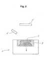
- the layered article, whose upper planar surface forms the target surface 2is moved downwardly in small steps during the construction process, so that the formed article is gradually buried in a construction container 7 (see FIG Fig. 2 ), wherein the target surface 2 is flush with the bottom of the process chamber 1.
- the radiation sensor or the infrared sensor 6In order to prevent the radiation sensor or the infrared sensor 6 from being impaired in its function during precipitation from monomers, oligomers or solid particles during a building process, it can be flown around by a tempered fluid according to the invention. As a result, a particularly effective temperature control of the surface of the sensor or its window and / or its lens can be achieved so that on the one hand precipitate formation of monomers and oligomers by tempering and rinsing of the surface is prevented, while on the other hand a precipitate formation by solid particles at least by the rinsing effect the fluid is prevented.
- the radiation sensor 6flows around a temperature-controlled fluid.
- Fig. 3is a schematic representation of the protective gas line 8, in which nitrogen or other inert gas or inert gas such as carbon dioxide or argon from a protective gas source 9 is passed through a flow meter 10 and by a heater 11 to a protective gas blowing attachment 12, the the in Fig. 2 shown radiation sensor or IR sensor 6 is coupled (see also Figs. 5A and 5B ), so that it is flowed around by the tempered inert gas.
- This ventilation of the sensor 6 with preheated inert gasprevents the formation of precipitate on the window 6a and the lens of the sensor 6th
- the protective gas emerging from the blowing attachment 12 and past the window 6a or the lens of the sensor 6, on the one hand,must flow sufficiently strong to prevent precipitation on the sensor 6, and on the other hand, must not flow too much to prevent it in that powder in the process space 1 is swirled or even the temperature distribution on the component is influenced.
- a typical volume of the process chamber 1is in the range of 0.2 m3 to 3 m3. Then, the flow rate or the flow rate of the tempered shielding gas, which flows around the sensor 6, 20 cm3 / min to 400 cm3 / min, preferably 50 cm3 / min to 200 cm3 / min, at a pressure of 0.3x10⁵ Pa to 3x10⁵ Pa , preferably from 0.6x10⁵ Pa to 1.2x10⁵ Pa.
- the upper temperature Tois the maximum permissible sensor operating temperature.
- the lower temperature Tuis the sensor surface temperature at which a significant precipitation of the vapors (monomers and oligomers) and the dusts (solid particles) takes place from the process chamber 1 on the sensor 6.
- the head temperatureis adjusted by the tempered inert gas flowing around it to a maximum temperature, the 10 ° C to 20 ° C, preferably 14 ° C to 16 ° C, lower than the maximum allowable head temperature of the sensor 6 is. Depending on the type of sensor, these values may change.
- the sensor 6has at the edge of its window 6a and / or its lens an attachment or a cover 14 (see Fig. 5A ), which consists of a thermally insulating material and thus forms a thermal insulating layer.
- the edge of the sensor window 6a and / or the sensor lens itselfmay also consist of a thermally insulating material. This ensures that the surface of the insulating layer 14 at the edge of the sensor window 6a or the sensor lens has substantially the same temperature as the processing space volume in which released material is located. In this way, it is ensured that even in the immediate vicinity of the sensor window 6a or the sensor lens no precipitate is formed, which could grow into the field of view of the sensor 6a in front of the window or lens until the window 6a or the lens would grow.
- Fig. 4Ashows a plan view of a disassembled arrangement (heating arrangement) of a heating element 11 and a protective gas passage 8 a, which forms part of the protective gas conduit 8.
- the protective gas passage 8ais formed on its outer surface complementary to the inner surface of the heating element 11, so that a good heat transfer between the heating element 11 and the protective gas passage 8a is ensured.
- the heating element 11is preferably an electrical, eg resistive heating element or a Peltier heating element.
- the contacting body of the heating element 11 and the protective gas passage 8aare preferably made of highly thermally conductive metals such as copper, aluminum or alloys containing these metals.
- Fig. 4Bshows a sectional view through the arrangement of Fig. 4A along the cutting plane X1-X2.
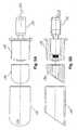
- Fig. 5Ashows a plan view of a partially disassembled arrangement (cooling / rinsing arrangement) for a sensor 6 (see Fig. 6 ), a protective gas blowing attachment 12 for generating a shielding gas veil surrounding the sensor 6, a cooling element 13 surrounding the sensor body 6b, an insulating element 14 surrounding the sensor window 6a and protecting the sensor 6, and a sleeve 15 which extends over the insulating attachment 14 and the cooling element 13 can be pushed.
- the contacting bodies of the cooling element 13 and the sensor body 6balso exist preferably made of highly thermally conductive metals such as copper, aluminum or alloys containing these metals.
- the protective gasis moved by the interaction of the cooling element 13 and the insulating attachment 14 approximately parallel or tangentially to the sensor window 6a or the sensor lens. This ensures both efficient temperature control and flushing of the sensor surface.
- Fig. 5Bshows a sectional view through the arrangement of Fig. 3A along the cutting plane X2-X2.
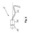
- Fig. 6shows a plan view of an IR sensor 6 with sensor lens 6a and body 6b, which is installed in the air blower insert.
- the sensor cable 6cis a shielded cable and connects the sensor electronics (eg integrated in the sensor) to the evaluation electronics.
- the separate cooling, temperature control and flushing of the respective sensor parts (sensor body 6b or sensor window 6a) described here by way of exampleis not restricted to a sensor, but can also be used analogously in the case of a laser or a surveillance camera, the separate cooling. Tempering and rinsing at the respective laser parts (laser body or laser window) or camera parts is used.
Landscapes
- Engineering & Computer Science (AREA)
- Chemical & Material Sciences (AREA)
- Materials Engineering (AREA)
- Manufacturing & Machinery (AREA)
- Physics & Mathematics (AREA)
- Optics & Photonics (AREA)
- Plasma & Fusion (AREA)
- Mechanical Engineering (AREA)
- Laser Beam Processing (AREA)
- Powder Metallurgy (AREA)
Abstract
Description
Translated fromGermanDie Erfindung bezieht sich auf ein Verfahren und eine Vorrichtung zur Herstellung eines dreidimensionalen Gegenstands durch ein thermisches generatives 3D-Verfahren, wie z.B. selektives Laser-Sintern (selective laser sintering, SLS), selektives Laser-Schmelzen (selective laser melting, SLM).The invention relates to a method and an apparatus for producing a three-dimensional object by a thermal generative 3D method, such as e.g. selective laser sintering (SLS), selective laser melting (SLM).
Bei einem generativen Verfahren erfolgt eine schichtweise Herstellung eines dreidimensionalen Gegenstands, wobei im allgemeinen die folgenden Schritte durchgeführt werden:
- ➢ schichtweises, insbesondere selektives, Auftragen von Material auf eine Zieloberfläche in einer Prozesskammer;
- ➢ Zuführen von Energie in die Schicht aus Material, um das Material innerhalb der Schicht und mit einer darunter liegenden Materialschicht des zu bildenden dreidimensionalen Gegenstands zu verschmelzen;
- ➢ Wiederholen der Schritte des Auftragens von Material und des Zuführens von Energie, um den Gegenstand schichtweise aufzubauen;
- ➢ wobei mittels mindestens eines elektromagnetischen Elements elektromagnetische Strahlung in die Prozesskammer eingestrahlt wird und/oder die Temperatur der Zieloberfläche und ggf. anderer Oberflächen im Innern der Prozesskammer durch Erfassen der von ihnen abgestrahlten Strahlung bestimmt wird.
- Layered, in particular selective, application of material to a target surface in a process chamber;
- ➢ supplying energy into the layer of material to fuse the material within the layer and with an underlying material layer of the three-dimensional object to be formed;
- ➢ repeating the steps of applying material and supplying energy to build the object in layers;
- Wherein electromagnetic radiation is radiated into the process chamber by means of at least one electromagnetic element and / or the temperature of the target surface and possibly other surfaces in the interior of the process chamber is determined by detecting the radiation emitted by them.
Ein Beispiel eines generativen Verfahrens ist selektives Laser-Sintern (SLS-Verfahren), das im wesentlichen die folgenden Schritte aufweist:
- ➢ Aufbringen einer Schicht aus Pulver auf eine Zieloberfläche;
- ➢ Zuführen von Energie an ausgewählten Stellen der Schicht, die einem Querschnitt des zu bildenden Gegenstands in der Schicht entsprechen, um das Pulver an den ausgewählten Stellen zu schmelzen;
- ➢ Wiederholen der Schritte des Aufbringens von Pulver und des Zuführens von Energie, um den Gegenstand schichtweise aufzubauen.
- ➢ Anschliessend wird das nicht geschmolzene Pulver vom Gegenstand entfernt.
- Applying a layer of powder to a target surface;
- ➢ supplying energy at selected locations of the layer corresponding to a cross-section of the article to be formed in the layer to melt the powder at the selected locations;
- ➢ Repeat the steps of applying powder and supplying energy to build up the object in layers.
- ➢ Then the unmelted powder is removed from the object.
Zum selektiven Verschmelzen des Pulvers auf der Zieloberfläche innerhalb der jeweiligen Schicht und mit der darunterliegenden schon verfestigten Schicht verwendet man einen auf einen möglichst kleinen Punkt in der Schichtebene fokussierten Laserstrahl, der eine Abtastbewegung innerhalb der jeweiligen Schicht durchführt und somit einen jeweiligen Querschnitt des zu bildenden Gegenstandes erzeugt. Der Laserstrahl "schreibt" bzw. "zeichnet" die jeweiligen massiven Bereiche der Querschnittsfläche, indem er hinter sich eine "Spur" geschmolzenen bzw. verschmolzenen Pulvers hinterlässt.For selective fusion of the powder on the target surface within the respective layer and with the underlying already solidified layer using a focused on a small point in the layer plane laser beam, which performs a scanning movement within the respective layer and thus a respective cross section of the object to be formed generated. The laser beam "writes" or "draws" the respective massive areas of the cross-sectional area, leaving behind it a "trace" of molten or fused powder.
Derartige SLS-Verfahren haben sich in den letzten Jahren zunehmend für die Herstellung von Prototypen für Versuchszwecke, für Fertigteile, die nur in kleiner Anzahl benötigt werden, oder für individualisierte Teile, wie Knochen-Implantate und dgl etabliert. In diesem Zusammenhang redet man auch von der raschen Herstellung von Prototypen (Rapid Prototyping, RP-Verfahren). Je nach den mechanischen Anforderungen an den herzustellenden dreidimensionalen Gegenstand werden reine Polymerpulver (z.B. PA, PBT, etc.) oder Pulvergemische verwendet, die z.B. Polymerpulver vermischt mit Glasspulver, Keramikpulver, Metallpulver oder anderen Füllmaterialien enthalten, deren Schmelzpunkt in der Regel höher liegt als der Schmelzpunkt des Polymermaterials. Gegebenenfalls werden auch reine Metallpulver oder Metallpulvergemische direkt verarbeitet.Such SLS methods have been increasingly established in recent years for the production of prototypes for experimental purposes, for finished parts that are needed only in small numbers, or for individualized parts, such as bone implants and the like. In this context, one speaks of the rapid production of prototypes (rapid prototyping, RP-method). Depending on the mechanical requirements of the three-dimensional article to be produced, pure polymer powders (e.g., PA, PBT, etc.) or powder mixtures, e.g. Polymer powder mixed with glass powder, ceramic powder, metal powder or other filler materials whose melting point is usually higher than the melting point of the polymer material. Optionally, pure metal powder or metal powder mixtures are processed directly.
Um in dem schichtweise aufgebauten Gegenstand Materialspannungen und Verformungen (Schrumpfen, Verziehen) sowie ein Sintern ausserhalb des fokussierten Laserstrahls zu vermeiden, ist es notwendig, die Temperatur der Zieloberfläche und des Prozessraumes ("Bauraum", in dem der Gegenstand aufgebaut wird) zu überwachen und ggf. zu steuern.In order to avoid material stresses and deformations (shrinkage, distortion) and sintering outside the focused laser beam in the layered object, it is necessary to monitor the temperature of the target surface and the process space ("space" in which the object is built) if necessary to control.
Zur Erfassung der Oberflächentemperatur der Zieloberfläche verwendet man z.B. Infrarot-Sensoren.To detect the surface temperature of the target surface, use e.g. Infrared sensors.
Für die Beeinflussung der Oberflächentemperatur der Zieloberfläche verwendet man im wesentlichen zwei Massnahmen. Einerseits führt man der Zieloberfläche grossflächig Strahlungsenergie z.B. über Infrarot-Strahler und punktuell über den fokussierten Laserstrahl zu. Andererseits lässt man ein temperaturgesteuertes (temperiertes) Gas wie z.B. Stickstoff oder Argon über die Zieloberfläche strömen, um neben der durch Abstrahlung abgegebenen Wärme von der Zieloberfläche einen weiteren Teil der Abwärme durch Wärmeleitung und Abtransport in dem Gas zu entfernen.Essentially, two measures are used to influence the surface temperature of the target surface. On the one hand, the target surface is extensively exposed to radiation energy, e.g. via infrared emitters and selectively over the focused laser beam. On the other hand, a temperature controlled (tempered) gas such as e.g. Nitrogen or argon flow over the target surface, in addition to the heat emitted by radiation from the target surface to remove a further portion of the waste heat by conduction and removal in the gas.
In der Praxis treten beim Betrieb solcher SLS-Anlagen jedoch mehrere Probleme im Zusammenhang mit den in den Prozessraum ragenden IR-Sensoren auf.In practice, however, several problems arise in the operation of such SLS systems in connection with the projecting into the process space IR sensors.
Bei solchen SLS-Verfahren werden in der Regel Pulvermaterialien verwendet, bei denen zumindest ein Teil des Pulvers ein Polymermaterial ist. Dies hat zur Folge, dass aufgrund der Aufheizung des Polymermaterials während des Bauprozesses Dämpfe (Monomere und Oligomere) in den Prozessraum gelangen, die sich auf einer IR-Linse (Gradientenlinse) oder einem IR-Fenster der temperierten IR-Sensoren niederschlagen und zu Messabweichungen führen, da die IR-Sensoren und deren Linsen bzw. Fenster deutlich kälter als der die Dämpfe enthaltende Prozessraum sind. Die Linsen oder Fenster müssen deshalb regelmässig mit Ethanol oder einem anderen starken Lösungsmittel gereinigt werden. Dadurch werden aber die Dichtungen zwischen der Linse oder dem Fenster und dem Sensor-Hauptkörper beschädigt und verlieren mit der Zeit ihre Dichtwirkung.In such SLS processes, powder materials are generally used in which at least part of the powder is a polymer material. This has the consequence that due to the heating of the polymer material during the building process vapors (monomers and oligomers) enter the process space, which are reflected on an IR lens (gradient lens) or an IR window of tempered IR sensors and lead to measurement errors since the IR sensors and their lenses or windows are significantly colder than the process space containing the vapors. The lenses or windows must therefore be regularly cleaned with ethanol or another strong solvent. As a result, however, the seals between the lens or the window and the sensor main body are damaged and lose their sealing effect over time.
Um derartige Niederschläge zu vermeiden, werden die IR-Sensoren auf möglichst hohe Temperaturen vorgeheizt. Dabei ist man einerseits bestrebt, die Temperatur der IR-Sensoren und ihrer Linsen bzw. Fenster auf einen möglichst hohen Wert einzustellen, um derartige Niederschläge so gering wie möglich zu halten. Andererseits ist man aber auch bestrebt, die Temperatur der IR-Sensoren auf einem möglichst niedrigen Wert zu halten, um eine optimale Funktion und lange Lebensdauer zu gewährleisten. Dies führt in der Regel dazu, dass man während eines längeren Bauprozesses (z.B. 20h bis 70h) entweder eine immer schlechter werdende Funktion des IR-Sensors durch Niederschläge in Kauf nehmen muss, oder dass man zwar während des Bauprozesses wenig Niederschlag auf dem Sensor erfährt, dafür aber verstärkt damit rechnen muss, dass der IR-Sensor aufgrund zu hoher Temperatur über eine zu lange Zeit hinweg vorzeitig funktionsuntüchtig wird. Besonders ärgerlich ist dies, wenn der IR-Sensor inmitten eines sehr langen Bauprozesses ausfällt.To avoid such precipitation, the IR sensors are preheated to the highest possible temperatures. On the one hand, the aim is to set the temperature of the IR sensors and their lenses or windows to the highest possible value in order to minimize such precipitation. On the other hand, one also strives to keep the temperature of the IR sensors to a value as low as possible in order to ensure optimum function and a long service life. this leads to As a rule, during a longer construction process (eg 20h to 70h) either an increasingly bad function of the IR sensor due to rainfall has to be taken into account, or during the construction process there is little rainfall on the sensor, but so on Increasingly, it has to be reckoned with that the IR sensor will prematurely become inoperable due to too high a temperature for a too long time. This is particularly annoying if the IR sensor fails in the middle of a very long construction process.
Das Vorheizen der IR-Sensoren erfolgt meist elektrisch oder induktiv. Dies führt zu Magnetfeldern, die den IR-Sensor umgeben. Dadurch wird die zur Verarbeitung des Sensorsignals verwendete Elektronik gestört.The preheating of the IR sensors is usually done electrically or inductively. This leads to magnetic fields surrounding the IR sensor. As a result, the electronics used to process the sensor signal is disturbed.
An einem Beispiel soll dies noch einmal verdeutlicht werden:An example will illustrate this:
Bei der Verarbeitung von PA12 (einer speziellen Sorte von Polyamid) für einen schichtweise aufgebauten Gegenstand arbeitet man mit einer Temperatur in der SLS-Prozesskammer von etwa 180°C. Die in die Prozesskammer ragenden marktüblichen IR-Sensoren haben eine maximal zulässige Kopftemperatur von 85°C. Um einen Niederschlag auf der Linse bzw. dem Fenster des IR-Sensors weitgehend zu verhindern, muss der IR-Sensor auf etwa 80°C vorgeheizt werden (Kopftemperatur). Für die Herstellung eines schichtweise aufgebauten Gegenstands mit vertikalen Abmessungen von etwa 300mm - 400mm benötigt man mit marktüblichen SLS-Anlagen eine Bauzeit von etwa 20h - 70h. Ein derartiger Bauprozess stellt jedes Mal ein Risiko dar, weil der IR-Sensor über derart lange Bauzeiten meist überhitzt und dann während des Bauprozesses defekt wird, so dass mitunter ein Grossteil des Bauprozesses "blind" und somit ohne richtige Steuerung/Regelung der Prozesstemperatur erfolgt, was zu den weiter oben genannten Qualitätseinbussen führt (Materialspannungen und Verformungen im aufgebauten Gegenstand). Dies hat zur Folge, dass man sehr rasch einige Tausend Euro an Pulver und Anlagenstunden verliert.When processing PA12 (a special grade of polyamide) for a layered article, the temperature in the SLS process chamber is about 180 ° C. The commercially available IR sensors protruding into the process chamber have a maximum permissible head temperature of 85 ° C. In order to prevent precipitation on the lens or the window of the IR sensor, the IR sensor must be preheated to about 80 ° C (head temperature). For the production of a layered object with vertical dimensions of about 300mm - 400mm, a construction time of about 20h - 70h is required with standard SLS systems. Such a construction process poses a risk each time because the IR sensor overheats over such long construction times and then becomes defective during the construction process, so that sometimes a large part of the construction process takes place "blindly" and thus without proper control of the process temperature, which leads to the aforementioned quality losses (material stresses and deformations in the built-up object). As a result, you quickly lose a few thousand euros in powder and plant hours.
Wie man sieht, können bei den bekannten SLS-Anlagen oder anderen Anlagen für die Durchführung generativer 3D-Verfahren die zur Überwachung und Steuerung/Regelung notwendigen IR-Sensoren sowie andere optische Elemente, insbesondere Laser, durch verschiedene Einflüsse in ihrer Funktionsweise und Lebensdauer beeinträchtigt werden.As you can see in the known SLS systems or other systems for the implementation of generative 3D methods for monitoring and control / regulation required IR sensors and other optical elements, in particular lasers, are affected by various influences in their operation and lifetime.
Die Einstrahlung der Wärmeenergie erfolgt durch ein sogenanntes Laserfenster, welches die Abgrenzung zwischen Energiequelle und Arbeitsraum darstellt. Ähnliche Probleme wie beim Sensor ergeben sich auch hier.The irradiation of the heat energy takes place through a so-called laser window, which represents the demarcation between energy source and working space. Similar problems as with the sensor also arise here.
Ähnliche Probleme wie beim selektiven Laser-Sintern (selective laser sintering, SLS) treten auch beim selektiven Laser-Schmelzen (selective laser melting, SLM).Similar problems to selective laser sintering (SLS) also occur in selective laser melting (SLM).
Der Erfindung liegt die Aufgabe zugrunde, eine Anlage zur Durchführung eines generativen 3D-Verfahrens (z.B. SLS-Anlage, SLM-Anlage) mit einem darin verwendeten IR-Sensor und ggf. Laser oder Elektronenstrahl (EBM), für das eingangs beschriebene generative Verfahren (SLS-Verfahren, SLM-Verfahren) derart zu verbessern, dass die geschilderten Nachteile des Stands der Technik weitgehend beseitigt werden können.The invention is based on the object of a system for carrying out a generative 3D method (eg SLS system, SLM system) with an IR sensor and possibly laser or electron beam (EBM) used therein, for the generative method described above (US Pat. SLS method, SLM method) in such a way that the described disadvantages of the prior art can be largely eliminated.
Diese Aufgabe wird vorrichtungsmässig durch Anspruch 1 und verfahrensmässig durch Anspruch 19 gelöst.This object is achieved by the device by claim 1 and procedurally by claim 19.
Die erfindungsgemässe Vorrichtung zur schichtweisen Herstellung eines dreidimensionalen Gegenstands durch ein generatives Verfahren umfasst eine Prozesskammer, in welcher der dreidimensionale Gegenstand nach und nach gebildet wird; ein Mittel zum, insbesondere selektiven, schichtweisen Auftragen von Material auf eine Zieloberfläche in der Prozesskammer und Miteinander-Verschmelzen der Materialschichten des zu bildenden dreidimensionalen Gegenstands; und mindestens ein elektromagnetisches Element zum Aussenden elektromagnetischer Strahlung in die Prozesskammer und/oder Empfangen elektromagnetischer Strahlung aus der Prozesskammer.The device according to the invention for the layer-by-layer production of a three-dimensional object by a generative method comprises a process chamber in which the three-dimensional object is gradually formed; a means for, in particular, selective, layered application of material to a target surface in the process chamber and fusion of the material layers of the three-dimensional object to be formed; and at least one electromagnetic element for emitting electromagnetic radiation into the process chamber and / or receiving electromagnetic radiation from the process chamber.
Erfindungsgemäss enthält die Vorrichtung ein Mittel zur Erzeugung eines Schleiers aus einem temperierten Fluid zwischen dem elektromagnetischen Element und dem Prozesskammer-Volumen.According to the invention, the device contains a means for producing a veil from a tempered fluid between the electromagnetic element and the process chamber volume.
Durch den Fluid-Schleier wird eine Barriere zwischen dem Prozesskammer-Volumen und dem elektromagnetischen Element aufgebaut, die verhindert, dass bei dem generativen Verfahren in das Prozesskammer-Volumen freigesetztes Material in Form von Feststoffpartikeln, Oligomeren oder Monomeren zu dem elektromagnetischen Element gelangt und sich auf diesem niederschlägt und dessen Funktion beeinträchtigt.The fluid veil establishes a barrier between the process chamber volume and the electromagnetic element, which prevents material released in the process chamber volume in the generative process from reaching the electromagnetic element in the form of solid particles, oligomers or monomers this affects and impaired its function.
Das elektromagnetische Element ist vorzugsweise ein optisches Element, das elektromagnetische Strahlung zur Energiezufuhr in die Prozesskammer aussendet oder elektromagnetische Strahlung aus der Prozesskammer empfängt.The electromagnetic element is preferably an optical element which emits electromagnetic radiation for supplying energy into the process chamber or receives electromagnetic radiation from the process chamber.
Bei dem elektromagnetischen Element handelt es sich insbesondere um einen optischen Sensor, insbesondere um einen Infrarot-Sensor. Derartige optische Sensoren werden bei vielen generativen Verfahren verwendet, um die Temperatur in der Prozesskammer und an der "Baustellenoberfläche" in dem Bauraum zu erfassen.The electromagnetic element is in particular an optical sensor, in particular an infrared sensor. Such optical sensors are used in many generative processes to detect the temperature in the process chamber and at the "construction site surface" in the packaging space.
Das elektromagnetische Element kann auch ein Laser sein. Ein Laser wird z.B. beim SLS-Verfahren und beim SLM-Verfahren verwendet, um die jeweils aufgetragenen Pulverschichten selektiv aufzuschmelzen und mit der darunterliegenden Produktebene zu verschmelzen.The electromagnetic element may also be a laser. A laser is e.g. used in the SLS process and the SLM process to selectively melt the respective powder layers applied and fuse them with the underlying product level.
Vorzugsweise ist ein Mittel zur Erzeugung eines Fluid-Schleiers an dem elektromagnetischen Element angeordnet. Das unmittelbar am elektromagnetischen Element angeordnete Mittel erzeugt einen, vorzugsweise temperierten, Fluid-Schleier am elektromagnetischen Element, wodurch Niederschläge an diesem zumindest erschwert werden.Preferably, a means for generating a fluid veil is disposed on the electromagnetic element. The means arranged directly on the electromagnetic element generates a, preferably tempered, fluid haze on the electromagnetic element, whereby precipitation on this is at least made more difficult.
Ein Mittel zur Erzeugung eines Fluid-Schleiers kann auch beabstandet von dem elektromagnetischen Element angeordnet sein. Dadurch wird während des generativen Verfahrens freigesetztes Material aus einem das elektromagnetische Element umgebenden Bereich ferngehalten.A means for producing a fluid veil may also be arranged at a distance from the electromagnetic element. As a result, material released during the generative process is kept away from an area surrounding the electromagnetic element.
Bei einer speziellen Ausführung ist ein erstes Mittel zur Erzeugung eines ersten, vorzugsweise temperierten, Fluid-Schleiers an dem elektromagnetischen Element angeordnet und ein zweites Mittel zur Erzeugung eines zweiten, nicht notwendigerweise temperierten, Fluid-Schleiers beabstandet von dem elektromagnetischen Element angeordnet. Dadurch entsteht eine doppelte Barriere, die freigesetztes Material von dem elektromagnetischen Element fernhält.In a specific embodiment, a first means for generating a first, preferably tempered, fluid veil is arranged on the electromagnetic element and a second means for generating a second, not necessarily tempered, fluid veil spaced from the electromagnetic element. This creates a double barrier that keeps released material from the electromagnetic element.
Zweckmässigerweise besitzt das elektromagnetische Element ein Gehäuse sowie ein Fenster und/oder eine Linse in dem Gehäuse, das bzw. die in die Prozesskammer gerichtet ist, wobei das Gehäuse des elektromagnetischen Elements vorzugsweise einen Kanal aufweist, der von dem temperierten Fluid durchströmbar ist. Dadurch lässt sich eine besonders wirkungsvolle Temperierung der Oberfläche des Fensters und/oder der Linse erreichen, so dass eine Niederschlagsbildung von Monomeren und Oligomeren, Dämpfe durch Temperierung und Spülung der Oberfläche verhindert wird, während eine Niederschlagsbildung durch Feststoffpartikel zumindest durch die Spülwirkung verhindert wird.Conveniently, the electromagnetic element has a housing and a window and / or a lens in the housing, which is directed into the process chamber, wherein the housing of the electromagnetic element preferably has a channel through which the tempered fluid can flow. As a result, a particularly effective temperature control of the surface of the window and / or the lens can be achieved, so that precipitation of monomers and oligomers, vapors by tempering and rinsing of the surface is prevented, while a precipitate formation is prevented by solid particles, at least by the rinsing action.
Zweckmässigerweise besitzt der Kanal eine Mündung im Bereich des Fensters bzw. der Linse des elektromagnetischen Elements. Dadurch bewegt sich das Fluid mit relativ hoher Geschwindigkeit relativ zu dem Fenster bzw. der Linse.Conveniently, the channel has an orifice in the region of the window or the lens of the electromagnetic element. As a result, the fluid moves at a relatively high speed relative to the window or the lens.
Besonders vorteilhaft ist es, wenn der Kanal im Mündungsbereich schräg zu dem Fenster bzw. der Linse ausgerichtet ist, damit das temperierte Fluid mit einer zur Fensterfläche bzw. Linsenoberfläche parallelen Strömungskomponente in die Prozesskammer austreten kann. Dadurch wird sowohl eine intensive Temperierung als auch Spülung der Oberfläche des Fensters und/oder der Linse und eine wirkungsvolle Verhinderung von Niederschlägen erreicht.It is particularly advantageous if the channel in the mouth region is aligned obliquely to the window or the lens so that the tempered fluid can escape into the process chamber with a flow component parallel to the window surface or lens surface. As a result, both an intensive tempering and flushing of the surface of the window and / or the lens and an effective prevention of precipitation is achieved.
Der Kanal kann ein das gesamte elektromagnetische Element umgebender Kanal sein, der sich zwischen einem das elektromagnetische Element unmittelbar umgebenden inneren Gehäusebereich und einem den Kanal umgebenden äusseren Gehäusebereich erstreckt. Auch diese Massnahme trägt zur Intensivierung der Temperierung des elektromagnetischen Elements bei. Insbesondere kann der Kanal senkrecht zur Strömungsrichtung einen kreisringförmigen oder von einem inneren und äusseren Polygon begrenzten Querschnitt aufweisen.The channel may be a channel surrounding the entire electromagnetic element, which extends between an inner housing portion directly surrounding the electromagnetic element and an outer housing portion surrounding the channel. This measure also contributes to the intensification of the temperature control of the electromagnetic element. In particular, the channel can have a circular cross-section or a cross-section bounded by an inner and outer polygon perpendicular to the flow direction.
Die erfindungsgemässe Vorrichtung kann eine Fluidquelle aufweisen, von der eine Fluidleitung zu dem elektromagnetischen Element führt. Ausserdem kann sie eine Fluidsenke aufweisen, über die das Fluid aus der Prozesskammer abgezogen wird. Insbesondere bei der Verwendung relativ kostspieliger Inertgase, wie z.B. Argon, ist es vorteilhaft, wenn die Fluidsenke mit der Fluidquelle in Fluidverbindung steht, so dass ein Fluidkreislauf gebildet wird, wobei das Fluid dann zwischen der Fluidsenke und der Fluidquelle aufbereitet wird.The device according to the invention can have a fluid source, from which a fluid line leads to the electromagnetic element. In addition, it can have a fluid sink, via which the fluid is withdrawn from the process chamber. Especially when using relatively expensive inert gases, e.g. Argon, it is advantageous if the fluid sink in fluid communication with the fluid source, so that a fluid circuit is formed, wherein the fluid is then treated between the fluid sink and the fluid source.
Bei einer speziellen Ausführung kann die Temperierung des elektromagnetischen Elements allein durch das umströmende Fluid erfolgen. Dadurch erübrigen sich z.B. weitere elektrische Heiz- oder Kühlelemente.In a specific embodiment, the temperature of the electromagnetic element can be controlled solely by the fluid flowing around. As a result, e.g. additional electrical heating or cooling elements.
Vorzugsweise besitzt das elektromagnetische Element eine am Rand seines Fensters und/oder seiner Linse angebrachte thermische Isolierschicht, oder der Rand seines Fensters und/oder seiner Linse besteht aus einem thermisch isolierenden Material. Dadurch wird gewährleistet; dass die Oberfläche der Isolierschicht am Rand des Fensters oder der Linse im wesentlichen dieselbe Temperatur wie das Prozessraum-Volumen hat, in dem sich freigesetztes Material befindet, so dass ein Niederschlag am Fenster oder Linsenrand und ein "Zuwachsen" des Fensters oder der Linse weitgehend verhindert wird.The electromagnetic element preferably has a thermal insulating layer attached to the edge of its window and / or its lens, or the edge of its window and / or its lens consists of a thermally insulating material. This ensures; that the surface of the insulating layer at the edge of the window or lens is at substantially the same temperature as the process space volume in which released material is located so that precipitation at the window or lens edge and "windowing" of the window or lens is substantially prevented becomes.
Bei dem erfindungsgemässen generativen Verfahren zur schichtweisen Herstellung eines dreidimensionalen Gegenstands erfolgt ein, insbesondere selektives, schichtweises Auftragen einer Schicht aus Material auf eine Zieloberfläche in einer Prozesskammer und ein Zuführen von Energie in die Schicht aus Material, um das Material innerhalb der Schicht und mit einer darunter liegenden Materialschicht des zu bildenden dreidimensionalen Gegenstands zu verschmelzen. Diese Schritte des Auftragens von Material und des Zuführens von Energie werden wiederholt durchgeführt, um den Gegenstand schichtweise aufzubauen. Mittels mindestens eines elektromagnetischen Elements wird dabei elektromagnetische Strahlung in die Prozesskammer eingestrahlt, und/oder die Temperatur der Zieloberfläche und ggf. anderer Oberflächen im Innern der Prozesskammer wird durch Erfassen der von ihnen abgestrahlten Strahlung bestimmt.In the inventive generative method of producing a three-dimensional object in layers, a selective layering of a layer of material on a target surface in a process chamber is carried out and energy is introduced into the layer of material around the material within and with the layer lying material layer of the three-dimensional object to be formed to merge. These steps of applying material and supplying energy are repeatedly performed to build the object in layers. By means of at least one electromagnetic element while electromagnetic radiation is radiated into the process chamber, and / or the temperature of the target surface and possibly other surfaces in the interior of the process chamber is determined by detecting the radiation emitted by them.
Erfindungsgemäss wird ein Schleier aus einem temperierten Fluid zwischen dem elektromagnetischen Element und dem Prozesskammer-Volumen erzeugt.According to the invention, a veil is produced from a tempered fluid between the electromagnetic element and the process chamber volume.
Vorzugsweise wird ein Schleier aus temperiertem Fluid an dem elektromagnetischen Element erzeugt. Dieser Schleier dient zur Spülung und Temperierung der Oberfläche des elektromagnetischen Elements, während ein Schleier aus nicht notwendigerweise temperiertem Fluid beabstandet von dem elektromagnetischen Element erzeugt wird. Dieser Schleier hat vorwiegend eine Spülfunktion bzw. Barrierefunktion.Preferably, a veil of tempered fluid is generated at the electromagnetic element. This veil serves to rinse and temper the surface of the electromagnetic element while creating a veil of not necessarily tempered fluid spaced from the electromagnetic element. This veil predominantly has a rinse function or barrier function.
Bei einer speziellen Ausführung wird ein erster Fluid-Schleier an dem elektromagnetischen Element erzeugt und ein zweiter Fluid-Schleier beabstandet von dem elektromagnetischen Element erzeugt, um eine doppelte Barriere gegen freigesetztes Material von dem elektromagnetischen Element zu bilden.In a specific embodiment, a first fluid veil is created on the electromagnetic element and a second fluid veil spaced from the electromagnetic element is created to form a dual barrier against released material from the electromagnetic element.
Als temperiertes Fluid kann ein insbesondere Stickstoff und/oder Argon aufweisendes Schutzgas verwendet werden, um ungewollte Oxidationen zu verhindern.As tempered fluid, a protective gas, in particular nitrogen and / or argon, may be used to prevent unwanted oxidation.
Das temperierte Fluid kann das elektromagnetische Element umströmen und eine Flüssigkeit aufweisen, wobei insbesondere die Flüssigkeit des temperierten Fluids nach dem Umströmen des elektromagnetischen Elements verdampft wird und als Dampf in die Prozesskammer gelangt. Dadurch kann das elektromagnetische Element gekühlt werden. Als das elektromagnetische Element umströmendes temperiertes Fluid wird vorzugsweise ein Schutzgas verwendet, in dem Flüssigkeitströpfchen mitgeführt werden, die während des Umströmens des elektromagnetischen Elements zumindest teilweise verdampfen.The tempered fluid can flow around the electromagnetic element and have a liquid, wherein in particular the liquid of the tempered fluid is evaporated after flowing around the electromagnetic element and passes as steam into the process chamber. Thereby, the electromagnetic element can be cooled. As the tempered fluid flowing around the electromagnetic element, a protective gas is preferably used in which liquid droplets are entrained which at least partially evaporate during the flow around the electromagnetic element.
Zweckmässigerweise beträgt das Volumen der Prozesskammer 0,2 m3 bis 3 m3, und die Durchflussmenge bzw. der Durchsatz des temperierten Fluids, welches das elektromagnetische Element umströmt, liegt zwischen 20 cm3/min und 400 cm3/min, vorzugsweise zwischen 50 cm3/min und 200 cm3/min, wobei der Druck im Bereich von 0,3x10⁵ Pa bis 3x10⁵ Pa, vorzugsweise von 0,6x10⁵ Pa bis 1,2x10⁵ Pa, liegt.Conveniently, the volume of the process chamber from 0.2 m3 to 3 m3 , and the flow rate or the flow rate of the tempered fluid, which flows around the electromagnetic element is between 20 cm3 / min and 400 cm3 / min, preferably between 50 cm3 / min and 200 cm3 / min, the pressure being in the range from 0.3x10⁵ Pa to 3x10⁵ Pa, preferably from 0.6x10⁵ Pa to 1.2x10⁵ Pa.
Weitere Vorteile, Merkmale und Anwendungsmöglichkeiten der Erfindung ergeben sich aus der nun folgenden Beschreibung eines nicht einschränkend aufzufassenden Ausführungsbeispiels anhand der Zeichnung, wobei:
- Fig. 1
- eine schematische Perspektivansicht einer Vorrichtung für selektives Laser- sintern (SLS-Maschine) ist, innerhalb der Gegenstände schichtweise gene- riert werden können;
- Fig. 2
- eine Schnittansicht durch die Vorrichtung von
Fig. 1 ist; - Fig. 3
- eine schematische Darstellung der Schutzgas-Leitung ist;
- Fig. 4A
- eine Draufsicht auf eine auseinandergebaute Anordnung aus einem Heiz- element und einer Schutzgas-Durchführung zeigt;
- Fig. 4B
- eine Schnittansicht durch die Anordnung von
Fig. 4A entlang der Schnittebe- ne B-B ist; - Fig. 5A
- eine Draufsicht auf eine teilweise auseinandergebaute Anordnung aus einem elektromagnetischen Element, einem Kühlelement und einem Mittel zum Er- zeugen eines Schutzgas-Schleiers zeigt; und
- Fig. 5B
- eine Schnittansicht durch die Anordnung von Fig. 3A entlang der Schnittebe- ne A-A ist.
- Fig. 6
- eine Draufsicht auf einen elektromagnetischen IR-Sensor.
- Fig. 1
- FIG. 2 is a schematic perspective view of a selective laser sintering (SLS) machine within which articles can be generated in layers; FIG.
- Fig. 2
- a sectional view through the device of
Fig. 1 is; - Fig. 3
- a schematic representation of the protective gas line is;
- Fig. 4A
- shows a plan view of a disassembled arrangement of a heating element and a protective gas duct;
- Fig. 4B
- a sectional view through the arrangement of
Fig. 4A along the section plane BB; - Fig. 5A
- shows a plan view of a partially disassembled arrangement of an electromagnetic element, a cooling element and a means for generating a protective gas veil; and
- Fig. 5B
- a sectional view through the arrangement of Fig. 3A along the section AA is AA.
- Fig. 6
- a plan view of an electromagnetic IR sensor.
Die Anlage enthält ausserdem (nicht gezeigte) Mittel zum Aufbringen einer Schicht aus Pulver auf eine Zieloberfläche 2 in der Prozesskammer 1. Dieses Pulver stammt aus Pulverbehältem 3, 4, die sich beiderseits von der Zieloberfläche befinden. Bei den Mitteln zum Aufbringen von Pulver auf die Zieloberfläche 2 handelt es sich z.B. um Walzen, die Pulver von den Pulverbehältem 3, 4 zu der Zieloberfläche 2 verschieben können, so dass eine dünne Pulverschicht auf der Zieloberfläche 2 abgelagert wird.The apparatus also includes means (not shown) for applying a layer of powder to a
Die Anlage enthält auch Mittel zum Zuführen von Energie an ausgewählten Stellen der Pulverschicht, die einem Querschnitt des zu bildenden Gegenstands in der Schicht entsprechen, um das Pulver an den ausgewählten Stellen zu schmelzen.The plant also includes means for supplying energy at selected locations of the powder layer corresponding to a cross-section of the article to be formed in the layer to melt the powder at the selected locations.
Für die Beeinflussung der Oberflächentemperatur der Zieloberfläche verwendet man im folgende Massnahmen:
- 1) Man führt der Zieloberfläche 2 grossflächig Strahlungsenergie z.B. über einen Infrarot-
Strahler 5 zu (sieheFig. 2 ); - 2) Man führt der Zieloberfläche 2 punktuell über einen fokussierten Laserstrahl Energie zu, um eine punktuelle Aufschmelzung des Pulvers zu erzielen;
- 3) Man lässt ein temperaturgesteuertes (temperiertes) Gas wie z.B. Stickstoff oder Argon über die
Zieloberfläche 2 strömen, um neben der durch Abstrahlung abgegebenen Wärmevon der Zieloberfläche 2 einen weiteren Teil der Abwärme durch Wärmeleitung und Abtransport in dem Gas zu entfernen.
- 1) Radiation energy is supplied to the
target surface 2 over a large area, for example via an infrared radiator 5 (seeFig. 2 ); - 2) Energy is selectively supplied to the
target surface 2 via a focused laser beam in order to achieve a selective melting of the powder; - 3) A temperature-controlled (tempered) gas such as nitrogen or argon is allowed to flow over the
target surface 2 to remove, in addition to the heat emitted by radiation from thetarget surface 2, a further portion of the waste heat by heat conduction and removal in the gas.
Mittels eines Strahlungssensors, z.B. in Form eines IR-Sensors 6, wird die von der Zieloberfläche und ggf. anderen Oberflächen (3, 4) im Innern der Prozesskammer abgestrahlte Strahlung erfasst, um die jeweilige Oberflächentemperatur zu bestimmen.By means of a radiation sensor, e.g. In the form of an
Die Information über diese Oberflächentemperaturen dient als Grundlage für eine Ansteuerung der Aufheizung (Massnahme 1) oder Abkühlung (Massnahme 3) zur Beeinflussung der Oberflächentemperatur der Zieloberfläche 2.The information about these surface temperatures serves as the basis for triggering the heating (measure 1) or cooling (measure 3) for influencing the surface temperature of the
Der Boden der Pulverbehälter 3, 4 wird während des Bauvorgangs in kleinen Schritten nach oben bewegt, so dass am Boden der Prozesskammer 1 stets Pulver bereitgestellt wird, das z.B. durch die Walzen oder ähnliche Mittel zu der Zieloberfläche 2 bewegt werden kann. Der schichtweise gebildete Gegenstand, dessen obere, ebene Fläche die Zieloberfläche 2 bildet, wird während des Bauvorgangs in kleinen Schritten nach unten bewegt, so dass der gebildete Gegenstand nach und nach in einem Baubehälter 7 versenkt wird (siehe
Um zu verhindern, dass der Strahlungssensor bzw. der Infrarot-Sensor 6 während eines Bauvorgangs durch Niederschläge aus Monomeren, Oligomeren oder Feststoffpartikeln in seiner Funktion beeinträchtigt wird, ist dieser erfindungsgemäss von einem temperierten Fluid umströmbar. Dadurch lässt sich eine besonders wirkungsvolle Temperierung der Oberfläche Sensors bzw. von dessen Fenster und/oder dessen Linse erreichen, so dass einerseits eine Niederschlagsbildung von Monomeren und Oligomeren durch Temperierung und Spülung der Oberfläche verhindert wird, während andererseits eine Niederschlagsbildung durch Feststoffpartikel zumindest durch die Spülwirkung des Fluids verhindert wird.In order to prevent the radiation sensor or the
Mit der in
- ➢ Aufbringen einer Schicht aus Pulver auf die
Zieloberfläche 2; - ➢ Zuführen von Energie an ausgewählten Stellen der Schicht, die einem Querschnitt des zu bildenden Gegenstands in der Schicht entsprechen, um das Pulver an den ausgewählten Stellen zu schmelzen;
- ➢ Wiederholen der Schritte des Aufbringens von Pulver und des Zuführens von Energie, um den Gegenstand schichtweise aufzubauen wobei die
Temperatur der Zieloberfläche 2 und ggf. anderer Oberflächen im Innern der Prozesskammer durch Erfassen der von ihnen abgestrahlten Strahlung mittels eines Strahlungssensors 6 erfasst wird.
- ➢ applying a layer of powder to the
target surface 2; - ➢ supplying energy at selected locations of the layer corresponding to a cross-section of the article to be formed in the layer to melt the powder at the selected locations;
- Repeating the steps of applying powder and supplying energy to build the object in layers whereby the temperature of the
target surface 2 and possibly other surfaces in the interior of the process chamber is detected by detecting the radiation emitted by them by means of aradiation sensor 6.
Erfindungsgemäss wird der Strahlungssensor 6 von einem temperierten Fluid umströmt.According to the invention, the
Das aus dem Blasaufsatz 12 und an dem Fenster 6a bzw. der Linse des Sensors 6 vorbei in die Prozesskammer 1 austretende Schutzgas muss einerseits ausreichend stark strömen, um eine Niederschlagbildung am Sensor 6 zu verhindern, und darf andererseits nicht zu stark strömen, um zu verhindern, dass Pulver im Prozessraum 1 verwirbelt wird oder gar die Temperaturverteilung am Bauteil beeinflusst wird.The protective gas emerging from the blowing
Ein typisches Volumen der Prozesskammer 1 liegt im Bereich von 0,2 m3 bis 3 m3. Dann beträgt die Durchflussmenge bzw. der Durchsatz des temperierten Schutzgases, welches den Sensor 6 umströmt, 20 cm3/min bis 400 cm3/min, vorzugsweise 50 cm3/min bis 200 cm3/min, bei einem Druck von 0,3x10⁵ Pa bis 3x10⁵ Pa, vorzugsweise von 0,6x10⁵ Pa bis 1,2x10⁵ Pa.A typical volume of the process chamber 1 is in the range of 0.2 m3 to 3 m3. Then, the flow rate or the flow rate of the tempered shielding gas, which flows around the
Bei der Temperierung des Sensors 6 durch Umströmen mit temperiertem Schutzgas muss man sich zwischen zwei kritischen Temperaturen bewegen. Die obere Temperatur To ist die maximal zulässige Sensor-Betriebstemperatur. Die untere Temperatur Tu ist die Sensor-Oberflächentemperatur, ab der eine nennenswerte Niederschlagbildung aus den Dämpfen (Monomere und Oligomere) und den Stäuben (Feststoffpartikel) aus der Prozesskammer 1 auf dem Sensor 6 stattfindet.When tempering the
Für einen typischen Sensor 6 mit maximal 80°C wird die Kopftemperatur durch das ihn umströmende temperierte Schutzgas auf eine Höchsttemperatur eingestellt, die 10°C bis 20°C, vorzugsweise 14°C bis 16°C, tiefer als die maximal zulässige Kopftemperatur des Sensors 6 ist. Je nach Sensortyp können sich diese Werte ändern.For a
Der Sensor 6 besitzt am Rand seines Fensters 6a und/oder seiner Linse einen Aufsatz bzw. eine Abdeckung 14 (siehe
Durch die gesonderte Anbringung der das Heizelement 11 enthaltenden HeizAnordnung und der das Kühlelement 13 enthaltenden Kühl/Spül-Anordnung und durch die Bereitstellung des Isolieraufsatzes 14 in der Kühl/Spül-Anordnung wird das Vorheizen bzw. Temperieren des Schutzgases von dem Kühlen des Sensors 6 entkoppelt.Due to the separate attachment of the
Selbstverständlich beschränkt sich die hier beispielhaft beschriebene gesonderte Kühlung, Temperierung und Spülung der jeweiligen Sensorteile (Sensorkörper 6b bzw. Sensorfenster 6a) nicht auf einen Sensor, sondern kann analog auch bei einem Laser oder einer Überwachungs-Kamera verwendet werden, wobei die gesonderte Kühlung. Temperierung und Spülung bei den jeweiligen Laserteilen (Laserkörper bzw. Laserfenster) bzw. Kamerateilen zur Anwendung kommt.Of course, the separate cooling, temperature control and flushing of the respective sensor parts (sensor body 6b or sensor window 6a) described here by way of example is not restricted to a sensor, but can also be used analogously in the case of a laser or a surveillance camera, the separate cooling. Tempering and rinsing at the respective laser parts (laser body or laser window) or camera parts is used.
Claims (27)
- A device for producing a three-dimensional object in a layered manner by means of a generative method, with:➢ a process chamber (1) in which the three-dimensional object is formed step by step;➢ a means for, in particular, selectively applying material in a layered manner onto a target surface (2) within the process chamber (1) and for melting together the material layers of the three-dimensional object to be formed; and➢ at least one electromagnetic element (5) for emitting electromagnetic radiation into the process chamber (1) and/or for receiving electromagnetic radiation from the process chamber,characterized in that the device comprises a means for generating a curtain from a tempered fluid between the electromagnetic element and the process chamber volume.
- The device according to claim 1,characterized in that the at least one electromagnetic element is an optical sensor (6), in particular an infrared sensor.
- The device according to claim 1 or claim 2,characterized in that the at least one electromagnetic element (5) is a laser.
- The device according to any one of the claims 1 to 3,characterized in that a means (9) for generating a fluid curtain is arranged on the electromagnetic element (5).
- The device according to any one of the claims 1 to 3,characterized in that a means (9) for generating a fluid curtain is arranged spaced apart from the electromagnetic element (5).
- The device according to any one of the claims 1 to 5,characterized in that a first means for generating a first fluid curtain is arranged on the electromagnetic element (5), and a second means for generating a second fluid curtain is arranged spaced apart from the electromagnetic element (5).
- The device according to any one of the claims 1 to 6,characterized in that the electromagnetic element (5) comprises a housing and, within the housing, a window and/or a lens directed into the process chamber.
- The device according to any one of the claims 4 to 7,characterized in that the housing of the electromagnetic element comprises a channel (8) through which the tempered fluid can flow.
- The device according to claim 7 or claim 8,characterized in that the channel comprises a port (12) in the region of the window or the lens of the electromagnetic element.
- The device according to claim 9,characterized in that the channel is aligned inclined to the window or the lens so that the tempered fluid can discharge into the process chamber with a flow component parallel to the window surface or lens surface.
- The device according to any one of the claims 8 to 10,characterized in that the channel is a channel which surrounds the entire electromagnetic element and which extends between an inner housing region directly surrounding the electromagnetic element and an outer housing region surrounding the channel.
- The device according to claim 11,characterized in that the channel comprises a cross section which is perpendicular to the flow direction and which is circular, or is bordered by an inner and an outer polygon.
- The device according to any one of the claims 1 to 12,characterized in that it comprises a fluid source from which a fluid line runs to the electromagnetic element.
- The device according to claim 13,characterized in that it comprises a fluid sink through which the fluid is discharged from the process chamber.
- The device according to claim 14,characterized in that the fluid sink is in fluid communication with the fluid source (9) in such a manner that a fluid circuit is formed.
- The device according to claim 15,characterized in that the fluid is treated between the fluid sink and the fluid source (9).
- The device according to any one of the claims 1 to 16,characterized in that the tempering of the electromagnetic element takes place by means of the cross-flowing fluid, in particular by means of the fluid only.
- The device according to any one of the claims 7 to 17,characterized in that the electromagnetic element (5) comprises a thermal insulation layer (14) attached on the edge of its window (6a) and/or its lens, or that the edge of its window and/or its lens consists of a thermally insulating material.
- A generative method for producing a three-dimensional object in a layered manner, in particular by using a device according to any one of the claims 1 to 18, comprising the steps of:➢ applying a layer of material in a layered manner, in particular in a selective manner, onto a target surface within a process chamber (1);➢ supplying energy into the layer of material to melt the material within the layer and to melt it into an underlying material layer of the three-dimensional object to be formed;➢ repeating the steps of applying material and of supplying energy to construct the object in a layered manner;➢ wherein by means of at least one electromagnetic element (5), electromagnetic radiation is emitted into the process chamber, and/or the temperature of the target surface and, if necessary, of other surfaces inside the process chamber is determined by detecting the radiation emitted therefrom,characterized in that a curtain from tempered fluid is generated between the electromagnetic element and the process chamber volume.
- The method according to claim 19,characterized in that a curtain from tempered fluid is generated on the electromagnetic element (5).
- The method according to claim 19,characterized in that a curtain from fluid is generated spaced apart from the electromagnetic element (5).
- The method according to any one of the claims 19 to 21,characterized in that a first fluid curtain is generated on the electromagnetic element (5) and that a second fluid curtain is generated spaced apart from the electromagnetic element (5).
- The method according to any one of the claims 19 to 22,characterized in that the tempered fluid is an inert gas and comprises in particular nitrogen and/or argon.
- The method according to anyone of the claims 19 to 23,characterized in that the tempered fluid flows around the electromagnetic element (5) and has a flow rate or a liquid.
- The method according to claim 24,characterized in that the liquid of the tempered fluid is evaporated after flowing around the electromagnetic element (5) and reaches the process chamber in the form of vapor.
- The method according to claim 24 or claim 25,characterized in that the tempered fluid flowing around the electromagnetic element (5) is an inert gas carrying liquid droplets which evaporate at least partially while flowing around the electromagnetic element.
- The method according to any one of the claims 19 to 26,characterized in that the volume of the process chamber is 0.2 m3 to 3 m3 and the throughput or the flow rate of the tempered fluid flowing around the electromagnetic element is between 20 cm3/min and 400 cm3/min, preferably between 50 cm3/min and 200cm3/min, at a pressure from 0.3 x 10⁵ Pa to 3 x 10⁵ Pa, preferably from 0.6 x 10⁵ Pa to 1.2 x 10⁵ Pa.
Applications Claiming Priority (2)
| Application Number | Priority Date | Filing Date | Title |
|---|---|---|---|
| DE102005030067ADE102005030067A1 (en) | 2005-06-27 | 2005-06-27 | Apparatus for producing objects using generative method, e.g. selective laser sintering, has system for generating mist of fluid between electromagnetic component and process chamber |
| PCT/CH2006/000344WO2007000069A1 (en) | 2005-06-27 | 2006-06-27 | Method and device for producing a 3d object by means of a generative 3d-method |
Publications (2)
| Publication Number | Publication Date |
|---|---|
| EP1896247A1 EP1896247A1 (en) | 2008-03-12 |
| EP1896247B1true EP1896247B1 (en) | 2010-04-28 |
Family
ID=36943832
Family Applications (1)
| Application Number | Title | Priority Date | Filing Date |
|---|---|---|---|
| EP06741669AActiveEP1896247B1 (en) | 2005-06-27 | 2006-06-27 | Method and device for producing a 3d object by means of a generative 3d-method |
Country Status (9)
| Country | Link |
|---|---|
| US (1) | US8414281B2 (en) |
| EP (1) | EP1896247B1 (en) |
| JP (1) | JP5324917B2 (en) |
| CN (1) | CN101208190B (en) |
| AT (1) | ATE465863T1 (en) |
| AU (1) | AU2006264193B2 (en) |
| CA (1) | CA2611080A1 (en) |
| DE (2) | DE102005030067A1 (en) |
| WO (1) | WO2007000069A1 (en) |
Cited By (1)
| Publication number | Priority date | Publication date | Assignee | Title |
|---|---|---|---|---|
| EP1743759B2 (en)† | 2005-07-16 | 2018-03-14 | Evonik Degussa GmbH | Use of cyclic oligomers in a forming process and object produced by this process |
Families Citing this family (61)
| Publication number | Priority date | Publication date | Assignee | Title |
|---|---|---|---|---|
| JP5301217B2 (en)* | 2008-08-22 | 2013-09-25 | パナソニック株式会社 | Manufacturing method and manufacturing apparatus for three-dimensional shaped object |
| GB2472783B (en)* | 2009-08-14 | 2012-05-23 | Norsk Titanium Components As | Device for manufacturing titanium objects |
| WO2011034985A1 (en)* | 2009-09-17 | 2011-03-24 | Sciaky, Inc. | Electron beam layer manufacturing |
| EP2498935B1 (en) | 2009-11-13 | 2015-04-15 | Sciaky Inc. | Process for layer manufacturing a three-dimensional work piece using scanning electron monitored with closed loop control |
| US8461474B2 (en) | 2010-03-31 | 2013-06-11 | Sciaky, Inc. | Raster methodology, apparatus and system for electron beam layer manufacturing using closed loop control |
| DE102010049443A1 (en)* | 2010-10-23 | 2012-04-26 | Mtu Aero Engines Gmbh | Component, in particular engine component, with an allocation feature and method |
| FR2981867B1 (en)* | 2011-10-26 | 2016-02-12 | Snecma | PROCESS FOR MANUFACTURING A METAL PIECE FOR AIRCRAFT TURBOJET ENGINE |
| US9415459B2 (en)* | 2012-04-06 | 2016-08-16 | Illinois Tool Works Inc. | Welding systems having non-contact temperature measurement systems |
| US9266182B2 (en) | 2012-04-06 | 2016-02-23 | Illinois Tools Works Inc. | Welding torch with a temperature measurement device |
| WO2014018100A1 (en)* | 2012-07-27 | 2014-01-30 | Pratt & Whitney Rocketdyne, Inc. | Solid axisymmetric powder bed for selective laser melting |
| JP5995202B2 (en)* | 2012-07-31 | 2016-09-21 | 株式会社アスペクト | Powder additive manufacturing apparatus and powder additive manufacturing method |
| EP2700459B1 (en)* | 2012-08-21 | 2019-10-02 | Ansaldo Energia IP UK Limited | Method for manufacturing a three-dimensional article |
| EP2969485B1 (en) | 2013-03-15 | 2019-06-05 | 3D Systems, Inc. | Chute for laser sintering systems |
| CN103171152B (en)* | 2013-03-29 | 2015-08-26 | 嵇魁 | The moulded head structure of 3D printer |
| DE102013109162A1 (en) | 2013-08-23 | 2015-02-26 | Fit Fruth Innovative Technologien Gmbh | Device for producing three-dimensional objects |
| FR3010334B1 (en)* | 2013-09-09 | 2015-09-25 | Michelin & Cie | POWDER BED DEPOSITION DEVICE ON SURFACE PROVIDED WITH AN ELECTROMAGNETIC RESPONSE PROBE, AND CORRESPONDING METHOD |
| TWI511823B (en) | 2013-12-20 | 2015-12-11 | 財團法人工業技術研究院 | Apparatus and method for controlling the additive manufacturing |
| US20170001379A1 (en)* | 2014-02-05 | 2017-01-05 | United Technologies Corporation | A self-monitoring additive manufacturing system and method of operation |
| CA2859414C (en)* | 2014-04-04 | 2017-03-14 | Matsuura Machinery Corporation | Metal powder processing equipment |
| US9486878B2 (en) | 2014-06-20 | 2016-11-08 | Velo3D, Inc. | Apparatuses, systems and methods for three-dimensional printing |
| DE102015017470B4 (en) | 2014-08-22 | 2025-07-17 | Divergent Technologies, Inc. | FAILURE DETECTION FOR ADDITIVE MANUFACTURING SYSTEMS |
| US9909397B2 (en) | 2014-08-27 | 2018-03-06 | Halliburton Energy Services, Inc. | Methods of fabricating sand control screen assemblies using three-dimensional printing |
| US9702228B2 (en)* | 2014-09-04 | 2017-07-11 | Baker Hughes Incorporated | Porous structure for downhole fluid control applications and method of manufacture |
| US10786948B2 (en) | 2014-11-18 | 2020-09-29 | Sigma Labs, Inc. | Multi-sensor quality inference and control for additive manufacturing processes |
| WO2016102970A1 (en) | 2014-12-23 | 2016-06-30 | Renishaw Plc | Additive manufacturing apparatus and methods |
| CN107428081B (en) | 2015-01-13 | 2020-07-07 | 西格马实验室公司 | Materials identification system and method |
| US10226817B2 (en) | 2015-01-13 | 2019-03-12 | Sigma Labs, Inc. | Material qualification system and methodology |
| US9863803B2 (en) | 2015-03-10 | 2018-01-09 | Technology Research Association For Future Additive Manufacturing | Optical processing head having a plurality of optical fibers arranged to surround the light guide and 3D shaping apparatus |
| WO2016142891A1 (en)* | 2015-03-12 | 2016-09-15 | Atomics Monkey Products Limited | Apparatus and method for production of three-dimensional objects |
| FR3041278B1 (en)* | 2015-09-23 | 2017-11-03 | Manutech-Usd | SYSTEM AND METHOD FOR ADDITIVE FABRICATION BY LASER FUSION OF A BED OF POWDER |
| US10207489B2 (en) | 2015-09-30 | 2019-02-19 | Sigma Labs, Inc. | Systems and methods for additive manufacturing operations |
| CN105215359A (en)* | 2015-10-08 | 2016-01-06 | 湖南顶立科技有限公司 | The lower metal dust of a kind of high-pressure inert gas protection increases material manufacture method |
| CN105252000B (en)* | 2015-10-08 | 2017-09-19 | 湖南顶立科技有限公司 | A kind of metal dust increasing material manufacturing method under super-pressure inert gas shielding |
| DE102015117238A1 (en)* | 2015-10-09 | 2017-04-13 | GEFERTEC GmbH | Machining module for an additive manufacturing device |
| US10065270B2 (en) | 2015-11-06 | 2018-09-04 | Velo3D, Inc. | Three-dimensional printing in real time |
| US10286603B2 (en) | 2015-12-10 | 2019-05-14 | Velo3D, Inc. | Skillful three-dimensional printing |
| US20170239719A1 (en) | 2016-02-18 | 2017-08-24 | Velo3D, Inc. | Accurate three-dimensional printing |
| EP3219415A1 (en)* | 2016-03-16 | 2017-09-20 | Linde Aktiengesellschaft | Method and device for the generative production of a three-dimensional component |
| KR20180122466A (en)* | 2016-03-30 | 2018-11-12 | 어플라이드 머티어리얼스, 인코포레이티드 | Lamination fabrication methods for ceramics using microwaves |
| EP3492244A1 (en) | 2016-06-29 | 2019-06-05 | VELO3D, Inc. | Three-dimensional printing system and method for three-dimensional printing |
| US11691343B2 (en) | 2016-06-29 | 2023-07-04 | Velo3D, Inc. | Three-dimensional printing and three-dimensional printers |
| US20180093418A1 (en) | 2016-09-30 | 2018-04-05 | Velo3D, Inc. | Three-dimensional objects and their formation |
| US20180126460A1 (en) | 2016-11-07 | 2018-05-10 | Velo3D, Inc. | Gas flow in three-dimensional printing |
| US20180186082A1 (en) | 2017-01-05 | 2018-07-05 | Velo3D, Inc. | Optics in three-dimensional printing |
| US10315252B2 (en) | 2017-03-02 | 2019-06-11 | Velo3D, Inc. | Three-dimensional printing of three-dimensional objects |
| DE102017104506A1 (en) | 2017-03-03 | 2018-09-06 | Cl Schutzrechtsverwaltungs Gmbh | Device for the additive production of three-dimensional objects |
| US10449696B2 (en) | 2017-03-28 | 2019-10-22 | Velo3D, Inc. | Material manipulation in three-dimensional printing |
| EP3431263B1 (en)* | 2017-07-21 | 2021-04-21 | CL Schutzrechtsverwaltungs GmbH | Method for operating at least one apparatus for additively manufacturing three-dimensional objects |
| US10710307B2 (en) | 2017-08-11 | 2020-07-14 | Applied Materials, Inc. | Temperature control for additive manufacturing |
| DE102017215911A1 (en)* | 2017-09-08 | 2019-03-14 | Sauer Gmbh | Laser machine tool with extraction system |
| US10272525B1 (en) | 2017-12-27 | 2019-04-30 | Velo3D, Inc. | Three-dimensional printing systems and methods of their use |
| CN107983959A (en)* | 2017-12-29 | 2018-05-04 | 西安赛隆金属材料有限责任公司 | A kind of vision system environmental control system |
| US10144176B1 (en) | 2018-01-15 | 2018-12-04 | Velo3D, Inc. | Three-dimensional printing systems and methods of their use |
| EP3546502A1 (en)* | 2018-03-27 | 2019-10-02 | Friedrich-Alexander-Universität Erlangen-Nürnberg | Method for producing a population of particles of polyethylene terephthalate or polybutylene terephthalate or of a copolymer comprising pet and/or pbt |
| JP7343484B2 (en)* | 2018-04-20 | 2023-09-12 | 大陽日酸株式会社 | Method for manufacturing metal objects |
| SG11202009711QA (en) | 2018-04-20 | 2020-11-27 | Taiyo Nippon Sanso Corp | Method for manufacturing metal printed object |
| US12280545B2 (en) | 2019-06-06 | 2025-04-22 | Nikon Slm Solutions Ag | Apparatus and method |
| CA3148849A1 (en) | 2019-07-26 | 2021-02-04 | Velo3D, Inc. | Quality assurance in formation of three-dimensional objects |
| US11225027B2 (en) | 2019-10-29 | 2022-01-18 | Applied Materials, Inc. | Melt pool monitoring in multi-laser systems |
| WO2021232146A1 (en) | 2020-05-21 | 2021-11-25 | Kilncore Inc. | High temperature, high pressure, powder-based, 3d printed object manufacturing |
| JP7727418B2 (en)* | 2021-06-10 | 2025-08-21 | 株式会社日立製作所 | Manufacturing method of layered object and layered manufacturing device |
Family Cites Families (37)
| Publication number | Priority date | Publication date | Assignee | Title |
|---|---|---|---|---|
| CH642891A5 (en)* | 1979-11-21 | 1984-05-15 | Laser Work Ag | METHOD AND DEVICE FOR PROCESSING A WORKPIECE BY LASER BEAM. |
| US5155321A (en) | 1990-11-09 | 1992-10-13 | Dtm Corporation | Radiant heating apparatus for providing uniform surface temperature useful in selective laser sintering |
| US5460758A (en)* | 1990-12-21 | 1995-10-24 | Eos Gmbh Electro Optical Systems | Method and apparatus for production of a three-dimensional object |
| DE4233812C1 (en)* | 1992-10-07 | 1993-11-04 | Eos Electro Optical Syst | METHOD AND DEVICE FOR PRODUCING THREE-DIMENSIONAL OBJECTS |
| US5352405A (en)* | 1992-12-18 | 1994-10-04 | Dtm Corporation | Thermal control of selective laser sintering via control of the laser scan |
| DE4300478C2 (en)* | 1993-01-11 | 1998-05-20 | Eos Electro Optical Syst | Method and device for producing a three-dimensional object |
| DE4302418A1 (en)* | 1993-01-28 | 1994-08-11 | Eos Electro Optical Syst | Method and device for producing a three-dimensional object |
| DE4309524C2 (en)* | 1993-03-24 | 1998-05-20 | Eos Electro Optical Syst | Method of making a three-dimensional object |
| DE4400523C2 (en)* | 1994-01-11 | 1996-07-11 | Eos Electro Optical Syst | Method and device for producing a three-dimensional object |
| EP0758952B1 (en)* | 1994-05-13 | 1998-04-08 | EOS GmbH ELECTRO OPTICAL SYSTEMS | Process and device for manufacturing three-dimensional objects |
| DE19511772C2 (en)* | 1995-03-30 | 1997-09-04 | Eos Electro Optical Syst | Device and method for producing a three-dimensional object |
| DE19514740C1 (en)* | 1995-04-21 | 1996-04-11 | Eos Electro Optical Syst | Appts. for producing three-dimensional objects by laser sintering |
| DE19516972C1 (en)* | 1995-05-09 | 1996-12-12 | Eos Electro Optical Syst | Device for producing a three-dimensional object by means of laser sintering |
| DE29513026U1 (en)* | 1995-08-16 | 1995-10-05 | Eos Electro Optical Syst | Device for producing an object in layers by means of laser sintering |
| DE19606128A1 (en)* | 1996-02-20 | 1997-08-21 | Eos Electro Optical Syst | Device and method for producing a three-dimensional object |
| DE19782307T1 (en)* | 1997-12-26 | 2001-02-01 | Mitsubishi Electric Corp | Laser processing machine |
| US6203861B1 (en)* | 1998-01-12 | 2001-03-20 | University Of Central Florida | One-step rapid manufacturing of metal and composite parts |
| DE19813742C1 (en)* | 1998-03-27 | 1999-07-15 | Eos Electro Optical Syst | Three-dimensional object manufacture and process equipment for faster, higher quality object manufacture |
| DE19846478C5 (en)* | 1998-10-09 | 2004-10-14 | Eos Gmbh Electro Optical Systems | Laser-sintering machine |
| DE19853947C1 (en)* | 1998-11-23 | 2000-02-24 | Fraunhofer Ges Forschung | Process chamber for selective laser fusing of material powder comprises a raised section in the cover surface above the structure volume, in which a window is arranged for the coupling in of the laser beam |
| DE19962625A1 (en)* | 1999-01-01 | 2000-07-06 | Linde Tech Gase Gmbh | Laser material processing so that focussed laser beam is guided on workpiece to be processed and optic in laser material processing head is protected with help of gas flow and protective |
| DE19928245B4 (en)* | 1999-06-21 | 2006-02-09 | Eos Gmbh Electro Optical Systems | Device for supplying powder for a laser sintering device |
| DE19937260B4 (en)* | 1999-08-06 | 2006-07-27 | Eos Gmbh Electro Optical Systems | Method and device for producing a three-dimensional object |
| DE19939616C5 (en)* | 1999-08-20 | 2008-05-21 | Eos Gmbh Electro Optical Systems | Device for the generative production of a three-dimensional object |
| JP2001269788A (en)* | 2000-03-27 | 2001-10-02 | Nissan Motor Co Ltd | Nozzle for laser welding |
| DE60114453T2 (en)* | 2000-11-27 | 2006-07-13 | National University Of Singapore | METHOD AND DEVICE FOR PREPARING A THREE-DIMENSIONAL METAL PART USING HIGH-TEMPERATURE DIRECT LASER MELTS |
| DE10105504A1 (en)* | 2001-02-07 | 2002-08-14 | Eos Electro Optical Syst | Powder treatment device for a device for producing a three-dimensional object, device for producing a three-dimensional object and method for producing a three-dimensional object |
| DE10235434A1 (en)* | 2002-08-02 | 2004-02-12 | Eos Gmbh Electro Optical Systems | Device for producing a three-dimensional object by e.g. selective laser sintering comprises a support and a material-distributing unit which move relative to each other |
| DE10236697A1 (en)* | 2002-08-09 | 2004-02-26 | Eos Gmbh Electro Optical Systems | Method and device for producing a three-dimensional object by means of sintering |
| DE10245617A1 (en)* | 2002-09-30 | 2004-04-08 | Eos Gmbh Electro Optical Systems | Device and method for producing three-dimensional objects in layers |
| DE112004000301B4 (en)* | 2003-02-25 | 2010-05-20 | Panasonic Electric Works Co., Ltd., Kadoma-shi | Method and device for producing a three-dimensional object |
| DE10310797B4 (en)* | 2003-03-12 | 2005-11-03 | Siemens Ag | Device for processing substrates, in particular of electrical circuit substrates, with laser |
| US6815636B2 (en) | 2003-04-09 | 2004-11-09 | 3D Systems, Inc. | Sintering using thermal image feedback |
| DE10342882A1 (en)* | 2003-09-15 | 2005-05-19 | Trumpf Werkzeugmaschinen Gmbh + Co. Kg | Apparatus and method for producing a three-dimensional shaped body |
| US6930278B1 (en) | 2004-08-13 | 2005-08-16 | 3D Systems, Inc. | Continuous calibration of a non-contact thermal sensor for laser sintering |
| DE202004017854U1 (en)* | 2004-11-17 | 2005-01-27 | Trumpf Laser Gmbh + Co. Kg | Laser welding device has moving unit which limits mixture of welding gases produced during laser welding and hot ambient air within focused laser beam to region close to workpiece |
| US7807947B2 (en)* | 2005-05-09 | 2010-10-05 | 3D Systems, Inc. | Laser sintering process chamber gas curtain window cleansing in a laser sintering system |
- 2005
- 2005-06-27DEDE102005030067Apatent/DE102005030067A1/ennot_activeWithdrawn
- 2006
- 2006-06-27JPJP2008517294Apatent/JP5324917B2/ennot_activeExpired - Fee Related
- 2006-06-27CACA002611080Apatent/CA2611080A1/ennot_activeAbandoned
- 2006-06-27USUS11/993,420patent/US8414281B2/enactiveActive
- 2006-06-27DEDE502006006858Tpatent/DE502006006858D1/enactiveActive
- 2006-06-27EPEP06741669Apatent/EP1896247B1/enactiveActive
- 2006-06-27AUAU2006264193Apatent/AU2006264193B2/ennot_activeCeased
- 2006-06-27CNCN2006800230897Apatent/CN101208190B/enactiveActive
- 2006-06-27WOPCT/CH2006/000344patent/WO2007000069A1/enactiveApplication Filing
- 2006-06-27ATAT06741669Tpatent/ATE465863T1/enactive
Cited By (1)
| Publication number | Priority date | Publication date | Assignee | Title |
|---|---|---|---|---|
| EP1743759B2 (en)† | 2005-07-16 | 2018-03-14 | Evonik Degussa GmbH | Use of cyclic oligomers in a forming process and object produced by this process |
Also Published As
| Publication number | Publication date |
|---|---|
| CN101208190A (en) | 2008-06-25 |
| CA2611080A1 (en) | 2007-01-04 |
| WO2007000069A1 (en) | 2007-01-04 |
| JP2008546536A (en) | 2008-12-25 |
| ATE465863T1 (en) | 2010-05-15 |
| JP5324917B2 (en) | 2013-10-23 |
| US20100111744A1 (en) | 2010-05-06 |
| CN101208190B (en) | 2012-07-11 |
| AU2006264193A1 (en) | 2007-01-04 |
| US8414281B2 (en) | 2013-04-09 |
| AU2006264193B2 (en) | 2010-12-23 |
| DE502006006858D1 (en) | 2010-06-10 |
| DE102005030067A1 (en) | 2006-12-28 |
| EP1896247A1 (en) | 2008-03-12 |
Similar Documents
| Publication | Publication Date | Title |
|---|---|---|
| EP1896247B1 (en) | Method and device for producing a 3d object by means of a generative 3d-method | |
| EP2340925B1 (en) | Process for generative production of a three-dimensional object with continuous heat supply | |
| EP2586597B1 (en) | Device for avoiding deposits on optical components in laser sintering | |
| EP3285944B1 (en) | Device, method and control unit for the generative production of a three-dimensional object | |
| EP3059076B1 (en) | Method and device for generating a three-dimensional object | |
| DE102018127678B4 (en) | Methods and systems for quality inference and quality control in additive manufacturing processes | |
| EP3245043B1 (en) | Device for the additive production of three-dimensional components | |
| EP2361751B1 (en) | Method and device for producing a three dimensional object, particularly suitable for use in microtechnology | |
| DE102014201818A1 (en) | Method and device for improved control of energy input in a generative layer construction process | |
| DE202009018133U1 (en) | Device for producing a three-dimensionally shaped object | |
| EP3235631B1 (en) | Device for performing a laser sintering method | |
| EP3305445B1 (en) | Method for the generative production of a three-dimensional component | |
| DE102015108131A1 (en) | Method and apparatus for additive manufacturing | |
| EP3318353A1 (en) | Method for the generative production of a three-dimensional component | |
| DE102012216515A1 (en) | Process for the layered production of low-distortion three-dimensional objects by means of cooling elements | |
| DE102007057450A1 (en) | Producing three-dimensional articles e.g. injection mold, comprises applying and pressing solidifyable fluid or powdered material layer on target surface, and illuminating selected part of the layer with energy beam or material beam | |
| EP3311983A1 (en) | Apparatus and process for additively manufacturing of three-dimensional objects | |
| DE102013201629A1 (en) | Generative and layer-wise production of component by e.g. laser, comprises layer-by-layer melting of metal powder located in space of component by laser, where energy required for melting is regulated depending on position of component | |
| DE102016211935B4 (en) | Apparatus and method for process monitoring in a build-up welding process | |
| EP3322548A1 (en) | Vacuum sls method for the additive manufacture of metallic components | |
| EP3740335A1 (en) | Method for determining data for improved control of a device for producing articles by the method of selective powder melting and device therefor | |
| EP3900869B1 (en) | Method and device for optical quality control in laser deposition welding | |
| DE102018127986A1 (en) | Method for operating a device for the additive production of a three-dimensional object | |
| DE102018112129A1 (en) | Method for the generative production of a component, device for carrying out the method and motor vehicle | |
| DE19937359C2 (en) | Device for heating components made of microwave-absorbing plastic |
Legal Events
| Date | Code | Title | Description |
|---|---|---|---|
| PUAI | Public reference made under article 153(3) epc to a published international application that has entered the european phase | Free format text:ORIGINAL CODE: 0009012 | |
| 17P | Request for examination filed | Effective date:20071130 | |
| AK | Designated contracting states | Kind code of ref document:A1 Designated state(s):AT BE BG CH CY CZ DE DK EE ES FI FR GB GR HU IE IS IT LI LT LU LV MC NL PL PT RO SE SI SK TR | |
| DAX | Request for extension of the european patent (deleted) | ||
| DAX | Request for extension of the european patent (deleted) | ||
| RAP1 | Party data changed (applicant data changed or rights of an application transferred) | Owner name:INSPIRE AG FUER MECHATRONISCHE PRODUKTIONSSYSTEME | |
| GRAP | Despatch of communication of intention to grant a patent | Free format text:ORIGINAL CODE: EPIDOSNIGR1 | |
| GRAS | Grant fee paid | Free format text:ORIGINAL CODE: EPIDOSNIGR3 | |
| GRAA | (expected) grant | Free format text:ORIGINAL CODE: 0009210 | |
| AK | Designated contracting states | Kind code of ref document:B1 Designated state(s):AT BE BG CH CY CZ DE DK EE ES FI FR GB GR HU IE IS IT LI LT LU LV MC NL PL PT RO SE SI SK TR | |
| REG | Reference to a national code | Ref country code:GB Ref legal event code:FG4D Free format text:NOT ENGLISH | |
| REG | Reference to a national code | Ref country code:CH Ref legal event code:EP | |
| REG | Reference to a national code | Ref country code:IE Ref legal event code:FG4D Free format text:LANGUAGE OF EP DOCUMENT: GERMAN | |
| REF | Corresponds to: | Ref document number:502006006858 Country of ref document:DE Date of ref document:20100610 Kind code of ref document:P | |
| REG | Reference to a national code | Ref country code:CH Ref legal event code:NV Representative=s name:MOETTELI & ASSOCIES SARL | |
| REG | Reference to a national code | Ref country code:NL Ref legal event code:VDEP Effective date:20100428 | |
| LTIE | Lt: invalidation of european patent or patent extension | Effective date:20100428 | |
| PG25 | Lapsed in a contracting state [announced via postgrant information from national office to epo] | Ref country code:SE Free format text:LAPSE BECAUSE OF FAILURE TO SUBMIT A TRANSLATION OF THE DESCRIPTION OR TO PAY THE FEE WITHIN THE PRESCRIBED TIME-LIMIT Effective date:20100428 Ref country code:NL Free format text:LAPSE BECAUSE OF FAILURE TO SUBMIT A TRANSLATION OF THE DESCRIPTION OR TO PAY THE FEE WITHIN THE PRESCRIBED TIME-LIMIT Effective date:20100428 Ref country code:LT Free format text:LAPSE BECAUSE OF FAILURE TO SUBMIT A TRANSLATION OF THE DESCRIPTION OR TO PAY THE FEE WITHIN THE PRESCRIBED TIME-LIMIT Effective date:20100428 Ref country code:ES Free format text:LAPSE BECAUSE OF FAILURE TO SUBMIT A TRANSLATION OF THE DESCRIPTION OR TO PAY THE FEE WITHIN THE PRESCRIBED TIME-LIMIT Effective date:20100808 | |
| REG | Reference to a national code | Ref country code:IE Ref legal event code:FD4D | |
| PG25 | Lapsed in a contracting state [announced via postgrant information from national office to epo] | Ref country code:FI Free format text:LAPSE BECAUSE OF FAILURE TO SUBMIT A TRANSLATION OF THE DESCRIPTION OR TO PAY THE FEE WITHIN THE PRESCRIBED TIME-LIMIT Effective date:20100428 Ref country code:SI Free format text:LAPSE BECAUSE OF FAILURE TO SUBMIT A TRANSLATION OF THE DESCRIPTION OR TO PAY THE FEE WITHIN THE PRESCRIBED TIME-LIMIT Effective date:20100428 Ref country code:LV Free format text:LAPSE BECAUSE OF FAILURE TO SUBMIT A TRANSLATION OF THE DESCRIPTION OR TO PAY THE FEE WITHIN THE PRESCRIBED TIME-LIMIT Effective date:20100428 Ref country code:IS Free format text:LAPSE BECAUSE OF FAILURE TO SUBMIT A TRANSLATION OF THE DESCRIPTION OR TO PAY THE FEE WITHIN THE PRESCRIBED TIME-LIMIT Effective date:20100828 | |
| BERE | Be: lapsed | Owner name:INSPIRE A.G. FUR MECHATRONISCHE PRODUKTIONSSYSTEME Effective date:20100630 | |
| PG25 | Lapsed in a contracting state [announced via postgrant information from national office to epo] | Ref country code:CY Free format text:LAPSE BECAUSE OF FAILURE TO SUBMIT A TRANSLATION OF THE DESCRIPTION OR TO PAY THE FEE WITHIN THE PRESCRIBED TIME-LIMIT Effective date:20100526 Ref country code:GR Free format text:LAPSE BECAUSE OF FAILURE TO SUBMIT A TRANSLATION OF THE DESCRIPTION OR TO PAY THE FEE WITHIN THE PRESCRIBED TIME-LIMIT Effective date:20100729 Ref country code:PL Free format text:LAPSE BECAUSE OF FAILURE TO SUBMIT A TRANSLATION OF THE DESCRIPTION OR TO PAY THE FEE WITHIN THE PRESCRIBED TIME-LIMIT Effective date:20100428 | |
| PG25 | Lapsed in a contracting state [announced via postgrant information from national office to epo] | Ref country code:DK Free format text:LAPSE BECAUSE OF FAILURE TO SUBMIT A TRANSLATION OF THE DESCRIPTION OR TO PAY THE FEE WITHIN THE PRESCRIBED TIME-LIMIT Effective date:20100428 Ref country code:IE Free format text:LAPSE BECAUSE OF FAILURE TO SUBMIT A TRANSLATION OF THE DESCRIPTION OR TO PAY THE FEE WITHIN THE PRESCRIBED TIME-LIMIT Effective date:20100428 Ref country code:MC Free format text:LAPSE BECAUSE OF NON-PAYMENT OF DUE FEES Effective date:20100630 Ref country code:EE Free format text:LAPSE BECAUSE OF FAILURE TO SUBMIT A TRANSLATION OF THE DESCRIPTION OR TO PAY THE FEE WITHIN THE PRESCRIBED TIME-LIMIT Effective date:20100428 Ref country code:PT Free format text:LAPSE BECAUSE OF FAILURE TO SUBMIT A TRANSLATION OF THE DESCRIPTION OR TO PAY THE FEE WITHIN THE PRESCRIBED TIME-LIMIT Effective date:20100830 | |
| PG25 | Lapsed in a contracting state [announced via postgrant information from national office to epo] | Ref country code:CZ Free format text:LAPSE BECAUSE OF FAILURE TO SUBMIT A TRANSLATION OF THE DESCRIPTION OR TO PAY THE FEE WITHIN THE PRESCRIBED TIME-LIMIT Effective date:20100428 Ref country code:SK Free format text:LAPSE BECAUSE OF FAILURE TO SUBMIT A TRANSLATION OF THE DESCRIPTION OR TO PAY THE FEE WITHIN THE PRESCRIBED TIME-LIMIT Effective date:20100428 Ref country code:RO Free format text:LAPSE BECAUSE OF FAILURE TO SUBMIT A TRANSLATION OF THE DESCRIPTION OR TO PAY THE FEE WITHIN THE PRESCRIBED TIME-LIMIT Effective date:20100428 | |
| PLBE | No opposition filed within time limit | Free format text:ORIGINAL CODE: 0009261 | |
| STAA | Information on the status of an ep patent application or granted ep patent | Free format text:STATUS: NO OPPOSITION FILED WITHIN TIME LIMIT | |
| PG25 | Lapsed in a contracting state [announced via postgrant information from national office to epo] | Ref country code:IT Free format text:LAPSE BECAUSE OF FAILURE TO SUBMIT A TRANSLATION OF THE DESCRIPTION OR TO PAY THE FEE WITHIN THE PRESCRIBED TIME-LIMIT Effective date:20100428 | |
| 26N | No opposition filed | Effective date:20110131 | |
| PG25 | Lapsed in a contracting state [announced via postgrant information from national office to epo] | Ref country code:BE Free format text:LAPSE BECAUSE OF NON-PAYMENT OF DUE FEES Effective date:20100630 | |
| REG | Reference to a national code | Ref country code:DE Ref legal event code:R082 Ref document number:502006006858 Country of ref document:DE Representative=s name:PRUEFER & PARTNER GBR, DE | |
| REG | Reference to a national code | Ref country code:GB Ref legal event code:732E Free format text:REGISTERED BETWEEN 20110804 AND 20110810 | |
| REG | Reference to a national code | Ref country code:FR Ref legal event code:TP | |
| REG | Reference to a national code | Ref country code:CH Ref legal event code:PUE Owner name:EOS GMBH ELECTRO OPTICAL SYSTEMS Free format text:INSPIRE AG FUER MECHATRONISCHE PRODUKTIONSSYSTEME UND FERTIGUNGSTECHNIK#LERCHENFELDSTRASSE 5#9014 ST. GALLEN (CH) -TRANSFER TO- EOS GMBH ELECTRO OPTICAL SYSTEMS#ROBERT-STIRLING-RING 1#82152 KRAILLING (DE) Ref country code:CH Ref legal event code:NV Representative=s name:R. A. EGLI & CO. PATENTANWAELTE | |
| REG | Reference to a national code | Ref country code:DE Ref legal event code:R082 Ref document number:502006006858 Country of ref document:DE Representative=s name:PRUEFER & PARTNER GBR, DE Effective date:20110805 Ref country code:DE Ref legal event code:R081 Ref document number:502006006858 Country of ref document:DE Owner name:EOS GMBH ELECTRO OPTICAL SYSTEMS, DE Free format text:FORMER OWNER: INSPIRE AG FUER MECHATRONISCHE PRODUKTIONSSYSTEME UND FERTIGUNGSTECHNIK, ST. GALLEN, CH Effective date:20110805 Ref country code:DE Ref legal event code:R082 Ref document number:502006006858 Country of ref document:DE Representative=s name:PRUEFER & PARTNER MBB PATENTANWAELTE RECHTSANW, DE Effective date:20110805 | |
| REG | Reference to a national code | Ref country code:AT Ref legal event code:PC Ref document number:465863 Country of ref document:AT Kind code of ref document:T Owner name:EOS GMBH ELECTRO OPTICAL SYSTEMS, DE Effective date:20120221 | |
| PG25 | Lapsed in a contracting state [announced via postgrant information from national office to epo] | Ref country code:BG Free format text:LAPSE BECAUSE OF FAILURE TO SUBMIT A TRANSLATION OF THE DESCRIPTION OR TO PAY THE FEE WITHIN THE PRESCRIBED TIME-LIMIT Effective date:20100428 Ref country code:LU Free format text:LAPSE BECAUSE OF NON-PAYMENT OF DUE FEES Effective date:20100627 Ref country code:HU Free format text:LAPSE BECAUSE OF FAILURE TO SUBMIT A TRANSLATION OF THE DESCRIPTION OR TO PAY THE FEE WITHIN THE PRESCRIBED TIME-LIMIT Effective date:20101029 | |
| PG25 | Lapsed in a contracting state [announced via postgrant information from national office to epo] | Ref country code:TR Free format text:LAPSE BECAUSE OF FAILURE TO SUBMIT A TRANSLATION OF THE DESCRIPTION OR TO PAY THE FEE WITHIN THE PRESCRIBED TIME-LIMIT Effective date:20100428 | |
| PGFP | Annual fee paid to national office [announced via postgrant information from national office to epo] | Ref country code:AT Payment date:20120711 Year of fee payment:7 | |
| PGFP | Annual fee paid to national office [announced via postgrant information from national office to epo] | Ref country code:CH Payment date:20130621 Year of fee payment:8 | |
| PG25 | Lapsed in a contracting state [announced via postgrant information from national office to epo] | Ref country code:BG Free format text:LAPSE BECAUSE OF FAILURE TO SUBMIT A TRANSLATION OF THE DESCRIPTION OR TO PAY THE FEE WITHIN THE PRESCRIBED TIME-LIMIT Effective date:20100728 | |
| REG | Reference to a national code | Ref country code:CH Ref legal event code:PL | |
| REG | Reference to a national code | Ref country code:AT Ref legal event code:MM01 Ref document number:465863 Country of ref document:AT Kind code of ref document:T Effective date:20140627 | |
| PG25 | Lapsed in a contracting state [announced via postgrant information from national office to epo] | Ref country code:LI Free format text:LAPSE BECAUSE OF NON-PAYMENT OF DUE FEES Effective date:20140630 Ref country code:CH Free format text:LAPSE BECAUSE OF NON-PAYMENT OF DUE FEES Effective date:20140630 | |
| PG25 | Lapsed in a contracting state [announced via postgrant information from national office to epo] | Ref country code:AT Free format text:LAPSE BECAUSE OF NON-PAYMENT OF DUE FEES Effective date:20140627 | |
| REG | Reference to a national code | Ref country code:FR Ref legal event code:PLFP Year of fee payment:11 | |
| REG | Reference to a national code | Ref country code:DE Ref legal event code:R079 Ref document number:502006006858 Country of ref document:DE Free format text:PREVIOUS MAIN CLASS: B29C0067000000 Ipc:B29C0064106000 | |
| REG | Reference to a national code | Ref country code:FR Ref legal event code:PLFP Year of fee payment:12 | |
| REG | Reference to a national code | Ref country code:FR Ref legal event code:PLFP Year of fee payment:13 | |
| P01 | Opt-out of the competence of the unified patent court (upc) registered | Effective date:20230525 | |
| PGFP | Annual fee paid to national office [announced via postgrant information from national office to epo] | Ref country code:DE Payment date:20241121 Year of fee payment:19 | |
| PGFP | Annual fee paid to national office [announced via postgrant information from national office to epo] | Ref country code:GB Payment date:20241120 Year of fee payment:19 | |
| PGFP | Annual fee paid to national office [announced via postgrant information from national office to epo] | Ref country code:FR Payment date:20241128 Year of fee payment:19 |