EP1896115B2 - Microneedle cartridge assembly - Google Patents
Microneedle cartridge assemblyDownload PDFInfo
- Publication number
- EP1896115B2 EP1896115B2EP06785522.1AEP06785522AEP1896115B2EP 1896115 B2EP1896115 B2EP 1896115B2EP 06785522 AEP06785522 AEP 06785522AEP 1896115 B2EP1896115 B2EP 1896115B2
- Authority
- EP
- European Patent Office
- Prior art keywords
- microneedle array
- web
- cartridge
- container
- microneedle
- Prior art date
- Legal status (The legal status is an assumption and is not a legal conclusion. Google has not performed a legal analysis and makes no representation as to the accuracy of the status listed.)
- Not-in-force
Links
Images


Classifications
- A—HUMAN NECESSITIES
- A61—MEDICAL OR VETERINARY SCIENCE; HYGIENE
- A61M—DEVICES FOR INTRODUCING MEDIA INTO, OR ONTO, THE BODY; DEVICES FOR TRANSDUCING BODY MEDIA OR FOR TAKING MEDIA FROM THE BODY; DEVICES FOR PRODUCING OR ENDING SLEEP OR STUPOR
- A61M37/00—Other apparatus for introducing media into the body; Percutany, i.e. introducing medicines into the body by diffusion through the skin
- A61M37/0015—Other apparatus for introducing media into the body; Percutany, i.e. introducing medicines into the body by diffusion through the skin by using microneedles
- A61M2037/0023—Drug applicators using microneedles
Definitions
- the present inventionrelates to microneedle array cartridges.
- stratum corneumthe outermost layer of the skin.
- microneedlesarrays of relatively small structures, sometimes referred to as microneedles or micro-pins, have been disclosed for use in connection with the delivery of therapeutic agents and other substances through the skin and other surfaces.
- the devicesare typically pressed against the skin in an effort to pierce the stratum corneum.
- the microneedle arraysare generally used once and then discarded.
- Microneedles on these devicespierce the stratum corneum upon contact, making a plurality of microscopic slits that serve as passageways through which molecules of active components (e.g., therapeutic agents, vaccines, and other substances) can be delivered into the body.
- active componentse.g., therapeutic agents, vaccines, and other substances
- the microneedle arraycan be provided with a reservoir for temporarily retaining an active component in liquid form prior to delivering the active component through the stratum corneum.
- the microneedlescan be hollow to provide a liquid flow path directly from the reservoir and through the microneedles to enable delivery of the therapeutic substance through the skin.
- active component(s)may be coated and dried on the microneedle array and delivered directly through the skin after the stratum corneum has been punctured.
- Transdermal adhesive patchesare also available and are generally constructed as an adhesive article with a pressure sensitive adhesive coated onto the surface of a backing comprised of a polymeric film, cloth or the like. Transdermal adhesive patches are provided with an adhesive that allows the patch to be releasably adhered to the surface of the skin where a predetermined dosage of an active component can be put in contact with a small surface area of the skin.
- An appropriate biocompatible carrieris normally provided to facilitate the absorption of molecules through the stratum corneum over a period of time while the patch remains adhered to the skin.
- WO-A-02/28471discloses a medical injection device for the intracutaneous administration of tat least one anesthetic.
- the devicecomprises one base surface across the surface of one side of which a plurality of injectors, especially hypodermic needles, are distributed. Said injectors have an injection depth that reaches down to maximally the subcutis of the animal or human to be treated.
- the medical injection device according to the inventionis further characterized in that a disinfectant is provided on the side of the base surface where the injectors are disposed.
- US-A-2002/0091357discloses a retainer provided for holding a microprotrusion member for application of the microprotrusion member to the stratum corneum with an impact applicator.
- the microprotrusion memberincludes a plurality of microprotrusions which penetrate the stratum corneum to improve transport of an agent across the stratum corneum.
- WO-A-2004/009470discloses a medicament dispenser for use with a medicament carrier having multiple distinct medicament doses carried thereby and an internal mechanism for dispensing the distinct medicament doses carried by said medicament carrier.
- the mechanismcomprises receiving means for receiving the medicament carrier, release means for releasing a distinct medicament dose from the medicament carrier on receipt thereof by said receiving means; an outlet, positioned to be in communication with the medicament dose releasable by said release means; indexing means for individually indexing the distinct medicament doses of the medicament carrier; and counting means for counting each time a distinct medicament dose of the medicament carrier is indexed by said indexing means.
- the counting meansis a distinct electronic counter unit that is reversibly receivable by the medicament dispenser.
- WO 03/059431refers to Microneedle devices and methods of manufacturing the microneedle devices.
- the microneedle devicesinclude microneedles protruding from a substrate, with the microneedles piercing a cover placed over the substrate surface from which the microneedles protrude.
- the cover and the microneedle substratetogether define a capillary volume in fluid communication with the base of each microneedle.
- One manner of using microneedle arrays of the present inventionis in methods involving the penetration of skin to deliver medicaments or other substances and/or extract blood or tissue. Manufacturing methods may include simultaneous application of pressure and ultrasonic energy when piercing the cover with the microneedle.
- EP 0429842 A2refers to a device for the transdermal administration of protein or peptide drug and to a transdermal administration method for protein or peptide drug that contacting and ionizing a protein or peptide drug immersed in hydrophilic polymer with ionizing solvent composition, and forming the drug pathway on epidermis by plural skin needles or treating the skin by a razor, and transferring the above ionized drug into the skin by electric force.
- Patches, with or without a microneedle arraycan have fragile and sanitary characteristics. It is generally desired that the patch and array not be contacted before application to a target site. This presents difficulties in storing and transporting patches to desired locations for eventual application.
- providing collars or other protection for microneedle arraysproduces bulky structures that require excessive amounts of materials to manufacture and take up large amounts of space during transportation and storage.
- loading a microneedle array on an applicator devicecan also be time consuming and difficult for operators.
- the present inventionprovides an alternative microneedle cartridge design.
- a microneedle array cartridgein a first aspect of the present invention, includes a web of material having a top face and an opposite bottom face. An adhesive and a microneedle array are disposed on the bottom face of the web of material.
- a containeris disposed relative to the bottom face of the web of material, and has a perimeter portion and a central portion for covering at least part of the microneedle array. At least part of the perimeter portion of the container contacts the adhesive, and the central portion of the container does not contact the adhesive.
- the perimeter portion and the central portion of the containerare integrally formed.
- the perimeter portion of the containerdefines a pair of cutout regions where the perimeter portion does not extend as far as the web perimeters.
- a microneedle array packagein another aspect of the present invention, includes a plurality of adhesive patches separably attached to each other, and each of the adhesive patches carrying a microneedle array cartridge according to any of the claims 1 to 16.
- a microneedle array cartridgein another aspect of the present invention, includes a web of material having a top face and an opposite bottom face, an adhesive, a microneedle array and a container.
- the web of materialis disposed substantially in a first plane.
- the adhesiveis disposed on the bottom face of the web of material.
- the microneedle arrayis disposed relative to the bottom face of the web of material.
- the containeris disposed relative to the bottom face of the web of material, and has a perimeter portion and a central portion for covering at least a portion of the microneedle array.
- a first region of the perimeter portionis disposed substantially in a second plane that is generally parallel to the first plane, and a second region of the perimeter portion is generally not disposed in the second plane.
- Patchescan be used for transdermal delivery of molecules, and can carry microneedle arrays, which have utility for the delivery of large molecules that are ordinarily difficult to deliver by passive transdermal delivery.
- arrayrefers to the medical devices described herein that include one or more structures capable of piercing the stratum corneum to facilitate the transdermal delivery of therapeutic agents or the sampling of fluids through or to the skin.
- Microstructure“microneedle” or “microarray” refers to the specific microscopic structures associated with the array that are capable of piercing the stratum corneum to facilitate the transdermal delivery of therapeutic agents or the sampling of fluids through the skin.
- microstructurescan include needle or needle-like structures as well as other structures capable of piercing the stratum corneum.
- the microneedlesare typically less than 500 microns in height, and sometimes less than 300 microns in height.
- the microneedlesare typically more than 20 microns in height, often more than 50 microns in height, and sometimes more than 125 microns in height.
- FIG. 1is a perspective view of a first embodiment of a microneedle cartridge 20 that includes a patch 22 and a container 24.
- FIG. 2is a cross-sectional view of the microneedle cartridge 20.
- the patch 22 shown in FIGS. 1 and 2includes a web of material 26 that forms a backing, and a microneedle array 28 supported by and attached to the web of material 26.
- the web of material 26is generally flat, and has an upper face 30 and a lower face 32.
- the web of material 26can be comprised of a polymeric film, cloth, nonwoven or the like.
- An adhesive 34such as a pressure sensitive adhesive, is disposed on the lower face 32 of the web of material 26.
- the microneedle array 28is located relative to the lower face 32 of the web of material 26 at a generally central portion of the web of material 26, which has a circular shape.
- the microneedle array 28can be attached to the web of material 26, for example, by adhesive, welding, heat bonding, and can be formed Integrally with the web of material 26.
- Suitable materials for the microneedle array 28include those selected from materials such as acrylonitrile-butadiene-styrene (ABS) polymers, polyphenyl sulfides, polycarbonates, polypropylenes, acetals, acrylics, polyetherimides, polybutylene terephthalates, polyethylene terephthalates as well as other known materials and combinations of two or more of the foregoing.
- ABSacrylonitrile-butadiene-styrene
- the microneedle array 28can carry molecules for eventual delivery through the stratum corneum of a patient's skin (i.e., the skin of a human or non-human test subject). Those molecules can be therapeutic agents, vaccines, and other materials.
- a reservoircan be included with the microneedle array 28 for holding molecules for eventual delivery. Deployment of the patch 22 to a target site permits the molecules to be delivered through or to the stratum corneum.
- the adhesive layerwill generally be selected according to the desired end use of the articles prepared by the present method.
- suitable adhesivesinclude acrylates, silicones, polyisobutylenes, synthetic rubber, natural rubber, and copolymers and mixtures thereof. Further description of suitable adhesives may be found in U. S. Patent Nos. 5,656,286 (Miranda et al. ), 4,693,776 (Krampe et al. ), 5,223,261 (Nelson et al. ), and 5,380,760 (Wendel et al. ).
- Typical examples of flexible films employed as conventional tape backings which may be useful as a backing filminclude those made from polymer films such as polypropylene; polyethylene, particularly low density polyethylene, linear low density polyethylene, metallocene polyethylenes, and high density polyethylene; polyvinyl chloride; polyester (e.g., polyethylene terephthalete); polyvinylidene chloride; ethylenevinyl acetate (EVA) copolymer; polyurethane; cellulose acetate; and ethyl cellulose.
- Coextruded multilayer polymeric filmsare also suitable, such as described in U. S. Patent No. 5, 783, 269 (Heilmann et al. ), the disclosure of which is incorporated herein by reference.
- Layered backingssuch as polyethylene terephthalate-aluminum-polyethylene composites and polyethylene terephthalate-EVA composites are also suitable.
- Foam tape backingssuch as closed cell polyolefin films used in 3MTM 1777 Foam Tape and 3MTM 1779 Foam Tape are also suitable.
- Polyethylenes, polyethylene blends, and polypropylenesare preferred polymer films. Polyethylenes and polyethylene blends are most preferred polymer films.
- the backing filmis translucent or transparent. Additives may also be added to the backing film, such as tackifiers, plasticizers, colorants, and anti-oxidants.
- the container 24is removably attached to the patch 22 to cover the microneedle array 28.
- the container 24includes a circular central base portion 36, a sidewall 38 connected at or near the perimeter of the central base portion 36, and a perimeter lip 40 connected to the sidewall 38 opposite the central base portion 36.
- a first portion 42 of the perimeter lip 40is adhesively affixed to the adhesive 34 on the web of material 26, and a second portion 44 of the perimeter lip 40 is spaced from the adhesive 34 so as not to adhere to it. This creates a gap or slight separation 46 (see FIG. 2 ).
- the gap 46facilitates separating the container 24 from the patch 22 for application of the patch 22 to a patient.
- a continuous adhesive connectionis formed around the microneedle array 28 between the web of material 26 and the perimeter lip 40 of the container 24. That continuous connection can form a seal.
- the sealmay be a hermetic seal, that is, a seal that can prevent entry or escape of air or other vapors, such as moisture vapor. Sealing the microneedle array 28 between the web of material 26 and the container 24 helps protect the microneedle array 28 from contamination and damage prior to deployment.
- the web of material 26may be considered to be disposed substantially in a first plane and the first portion 42 of the perimeter lip 40 is disposed substantially in a second plane that is generally parallel to the first plane.
- the web 26 and first portion 42are largely planar, but that minor variations, for example, due to manufacturing imperfections or due to the flexibility in the web and/or the carrier material may cause slight, but insignificant, deviations from planarity.
- the second portion 44 of the perimeter lip 40is generally not disposed in the second plane.
- the shape of the containeris a cylinder, but it should be understood that other shapes are suitable as long as the base portion is appropriately spaced from the microneedle array 28.
- the central base portion 36 and sidewall 38may have the form of a dome, in which case there may be no discernable boundary between the sidewall 38 and the central base portion 36.
- the sidewallsmay be angled and in some embodiments may extend until they contact an opposing sidewall, for example, forming a cone-shaped container.
- the containermay have additional exterior protrusions or indentations to facilitate handling and/or storage.
- a handling tabmay be affixed to the exterior surface of the base portion to make the container more easily graspable.
- the central base portion 36 and the sidewall 38 of the container 24define a volume in which the microneedle array 28 can rest.
- the container 24is spaced from the microneedle array 28, as the microneedle array 28 is generally susceptible to damage from contact during storage, transportation, and at other times prior to deployment.
- the container 24can have a relatively low profile, such that the sidewall 38 of the container 24 preferably has as small a height, H, as possible without damaging or risking damage to the microneedle array 28 through contact.
- a low profile container 24reduces space occupied by the cartridge 20, for storage and transportation purposes, while still providing protection to the microneedle array 28.
- a low profile container 24also reduces the amounts of gases (i.e., air) and contaminants that are exposed to the microneedle array 28 and molecules carried thereon. Because many molecules intended for delivery with the microneedle array 28 can have limited lifespans and may be sensitive to contamination and deterioration, a low profile container 24 reduces the volume of air that is exposed to the microneedle array 28 to limit such negative effects.
- a suitable low-profile heightwill depend upon the nature of the patch 22 and microneedle array 28, but the height will typically be less than 2.0 cm, often less than 1.5 cm, and sometimes less than 1.0 cm.
- the container 24can be formed of a polymer material. Generally, a rigid material is selected in order to better protect the microneedle array 28 from damage and to facilitate storage (e.g., for stacking a plurality of microneedle cartridges 20). In one embodiment, the container 24 is a transparent or translucent material. In one embodiment, the container 24 is opaque to protect the microneedle array 28 from exposure to light.
- FIG. 3is a partial cross-sectional view of the microneedle cartridge 20 held on an applicator device 50.
- the applicator device 50has a skin-contacting face 52, a recess 54, a substantially circular opening 56 defined in a bottom portion 58 of the recess 54, and a pair of retainer members 60 that each have substantially flat upper surfaces 62.
- the retainer members 60are generally elongate and their substantially flat upper surfaces 62 are generally parallel to and facing the bottom portion 58 of the recess 54.
- the pair of retainer members 60are located at opposite portions of the opening 56 and are connected at one side of the recess 54.
- the retainer members 60define an opening at one end for accepting patches between the retainer members 60 and the bottom portion 58 of the recess 54.
- the upper surfaces 62 of the retainer members 60may be non-stick or release surfaces.
- a non-stick or release surfacecan be achieved, for example, by a non-stick or release coating applied to the upper surfaces 62.
- the non-stick or release coatingcan be selected according to the desired use of the applicator device 50. For instance, a release coating, such as a low surface energy silicone, fluoropolymer, or fluoro-silicone release coating, can be selected based upon the adhesives used with patches applied using the patch application device 50
- the patch 22is disposed between the retainer members 60 and the bottom portion 58 of the recess 54.
- the microneedle array 28 carried by the patch 22faces away from opening 56 in the applicator device 50.
- the patch 22contacts the upper surfaces 62 of the retainer members 60, but generally does not adhere firmly to the retainer members 60 due to the non-stick or release character of the upper surfaces 62.
- FIG. 4is a perspective view of the patch 22 mounted on the applicator device 50.
- the patch 22In a fully mounted position, as shown in FIG. 4 , the patch 22 is generally aligned relative to the opening 56 in the applicator device 50 (the opening 56 is not visible in FIG. 4 ).
- the retainer members 60have cutaway portions 64 that provide an enlarged, partially circular open region that is generally aligned with the opening 56 on the bottom portion 58 of the recess 54.
- the open region defined by the cutaway portions 64facilitates patch application by reducing the amount of deflection of the patch 22 required to move the patch 22 from a mounted position on the applicator device 50 to a target location, during deployment.
- Further details of applicators suitable for use with microneedle array cartridges of the present inventionmay be found in U. S. Patent Application Serial No. 60/694,447 (Attorney Docket No. 60874US002) filed on June 27, 2005.
- the microneedle cartridge 20allows for simple and easy mounting of the patch 22 to the applicator device 50, for eventually applying the microneedle array 28 (the array 28 is not visible in FIG. 4 ) to a target site.
- Mounting the microneedle patch 22 on the applicator device 50includes the following steps. First, the microneedle cartridge 20, with the container 24 affixed thereto, is partially slid onto the retainer members 60. Ends of the retainer members 60 are positioned in the gap 46 formed between the web of material 26 and the perimeter lip 40 of the container 24 of the microneedle cartridge 20.
- microneedle cartridge 20is slid further along the retainer members 60, simultaneously separating the container 24 from the web of material 26, until the patch 22 is fully mounted on the applicator device 50 (e.g., such that the microneedle array 28 is aligned with the opening 56 defined in the bottom portion 58 of the recess 54).
- the container 24is removed from (i.e., separated from) the patch 22 to uncover and expose the microneedle array 28 prior to microneedle deployment.
- a mounting fixture 100may be used to assist in mounting the patch 22 of the microneedle cartridge 20 to the applicator device 50.
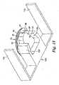
- a perspective view of the bottom of a mounting fixture 100is shown in FIG. 13 .
- the mounting fixture 100comprises alignment members 110 and cartridge holder members 120.
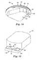
- the cartridge 20(shown in more detail in FIG. 14 ) includes a patch 22 and a container 24.
- the patch 22includes a web of material 26 that forms a backing, and a microneedle array 28 (not shown) supported by and attached to the web of material 26.
- An adhesive 34such as a pressure sensitive adhesive, is disposed on the lower face 32 of the web of material 26.
- the container 24is removably attached to the patch 22 to cover the microneedle array 28.
- the container 24includes an asymmetric central base portion 36, a sidewall 38 connected at or near the perimeter of the central base portion 36, and a perimeter lip 40 connected to the sidewall 38 opposite the central base portion 36. A second portion 44 of the perimeter lip 40 is spaced from the adhesive 34 so as not to adhere to it.
- the gap 46facilitates separating the container 24 from the patch 22 for application of the patch 22 to a patient.
- the asymmetric shape of the central base portion 36may be selected so as to mate with the opening provided by the cartridge holder members 120 in an orientation that presents the gap 46 to the front of the mounting fixture 100. This prevents the user from accidentally misaligning the gap 46 with respect to the applicator device 50.
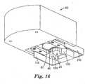
- the mounting fixture 100 with mounted cartridge 20is shown partially mated with an applicator device 50 in FIGS. 15 and 16 .
- the alignment guides 110contact an outer recess 55, thus providing for alignment of the cartridge 20 with the retainer members 60 of the applicator 50.
- the mounting fixturemay be used to fully insert the cartridge 20 into the applicator 50, at which time the mounting fixture 100 and container 24 may be removed, thereby leaving the patch 22 mounted in the applicator 50.
- the mounting fixturemay be easily grasped by a user or otherwise fixed in space, so that the user may bring the applicator 50 towards the stationary mounting fixture to load the patch 22 into the applicator 50.
- the mounting fixture 100may be part of a base station that holds multiple cartridges 20 and advances them to the cartridge holder members 120 one at a time.
- the mounting fixture 100may be integrated with packaging material used to hold one or more cartridges 20.
- a box of cartridgesmay have a mounting fixture affixed to an outside surface so that a user could remove a cartridge from the box, place the cartridge in the mounting fixture, and load the cartridge into the applicator as described above.
- a tray holding multiple cartridgescould be provided, wherein each cartridge is held in a mounting fixture integrally molded into the tray. Thus each cartridge could be directly loaded from the tray into an applicator.
- FIGS. 3 and 4The mounting configuration shown in FIGS. 3 and 4 is provided by way of example, and not limitation. In further embodiments, other means of mounting a patch on the applicator device can be used. For instance, in further embodiments, one or more patches can be stored inside the applicator device 50 prior to application, and then dispensed for application to a target site.
- FIGS. 5-8show a second embodiment of a microneedle cartridge 70.
- FIG. 5is a perspective view of the microneedle cartridge 70.
- FIG. 6is a front cross-sectional view of the microneedle cartridge 70, and
- FIG. 7is a side cross-sectional view of the microneedle cartridge 70.
- FIG. 8is a bottom view of the microneedle cartridge 70.
- the microneedle cartridge 70includes a patch 22 and a container 24.
- the patch 22includes a web of material 26, a microneedle array 28 and an adhesive 34 on a bottom face 32 of the web of material 26, and is generally similar to that shown and described with respect to FIGS. 1-4 above.
- the container 24is removably attached to the patch 22 to cover the microneedle array 28.
- the container 24includes a circular central base portion 36, a sidewall 38 connected at or near the perimeter of the central base portion 36, and a perimeter lip 40 connected to the sidewall 38 opposite the central base portion 36.
- a pair of opposed cutouts 72are provided in the perimeter lip 40. The cutouts 72 in the perimeter lip 40 make the container 24 smaller than a width or diameter of the patch 22 in particular regions, and expose portions of the adhesive 34 on the bottom face 32 of the web of material 26.
- a pair of stiffeners 74are provided on an upper face 30 of the web of material 26.
- the stiffeners 74provide additional rigidity to the patch 22 in order to reduce flexing, bending and other undesired deformation of the microneedle array 28 prior to and during handling and deployment.
- the stiffeners 74will reduce flexing in the area of the patch 22 that is suspended above the central base portion 36.
- the stiffeners 74are parallel to each other and generally aligned relative to the sidewall 38 of the container 24.
- more or fewer stiffeners 74can be provided.
- the stiffeners 74can be provided at different locations on the patch 22 than those shown in FIGS. 6-8 .
- the stiffeners 74are optional and that in certain embodiments the patch 22 may have sufficient resistance to bending or flexing without the need for additional stiffeners 74.
- the microneedle array 28may extend near or up to the inner surface of the sidewalls 38 and thereby provide sufficient rigidity in the suspended portion of the patch 22.
- FIG. 9is a perspective view of a third embodiment of a microneedle cartridge 80.
- FIG. 10is a cross-sectional view of the microneedle cartridge 80.
- the microneedle cartridge 80includes a patch 22 and a container 24.
- the patch 22includes a web of material 26, a microneedle array 28 and an adhesive 34 on a bottom face 32 of the web of material 26, and is generally similar to those shown and described with respect to FIGS. 1-8 above.
- the containeris removably attached to the patch 22 to cover the microneedle array 28.
- the container 24includes a circular central base portion 36, a sidewall 38 connected at or near the perimeter of the central base portion 36, and a perimeter lip 40 connected to the sidewall 38 opposite the central base portion 36.
- a gasket 82is disposed to adhere to the lip 40 of the container 24 and patch (i.e., to the web of material 26 or the adhesive 34).
- the gasket 82is disposed in a substantially continuous band around the microneedle array 28 in order to form a seal between the patch 22 and the container 24.
- the gasket 82is an adhesive.
- a different adhesivemay be used for the gasket than that used for the adhesive 34 adhered to the bottom face 32 of the web of material 26.
- Inserting the cartridge 80 into an applicator devicecan be generally similar to that described above with respect to FIGS. 1-8 . Additionally, the seal formed by the gasket 82 can be broken during an inserting procedure. For example, an operator can rotate the cartridge 80 relative to an applicator device to slice or otherwise break the seal using a blade or other means disposed on the applicator device.
- FIG. 11is a perspective view of a number of microneedle cartridges 90 arranged as a sheet 92.
- the sheet 92includes a liner 94 on which the cartridges 90 are carried.
- the individual cartridges 90can be removably adhered to the liner 94, or secured together by other methods.
- perforations 96can be provided in the liner 94 for separating individual cartridges 90.
- FIG. 12is a side view of a number of microneedle cartridges 90 arranged as a roll 98.
- the roll 98includes a liner 94 on which the cartridges 90 are carried and a core 99 around which the liner 94 is wound.
- the individual cartridges 90can be removably adhered to the liner 94, or secured together by other methods.
- perforations 96can be provided in the liner 94 for separating individual cartridges 90.
- the packages shown and described with respect to FIGS. 11 and 12permit storage of a plurality of cartridges in close proximity to each other. Individual ' cartridges can be separated from the others as desired for use. Those packages can also help reduce time between microneedle array deployments, by facilitating "reloading" of applicator devices between array deployments.
- Applicators used to apply a microneedle array or patchwill typically accelerate the microneedle device to reach a desired velocity that is effective to pierce the microneedles into the skin.
- the desired velocityis preferably controlled to limit or prevent stimulation of the underlying nerve tissue.
- the maximum velocity achieved by the microneedle array upon impact with the skinis often 20 meters per second (m/s) or less, potentially 15 m/s or less, and possibly 10 m/s or less. In some instances, the maximum velocity be 8 m/s or less. In other instances, the minimum velocity achieved by the microneedle array upon impact with the skin is often 2 m/s or more, potentially 4 m/s or more, and possibly 6 m/s or more.
- microneedle arrays useful in the various embodiments of the inventionmay comprise any of a variety of configurations, such as those described in the following patents and patent applications, the disclosures of which are herein incorporated by reference.
- One embodiment for the microneedle arrayscomprises the structures disclosed in United States Patent Application Publication No. 2003/0045837 .
- the disclosed microstructures in the aforementioned patent applicationare in the form of microneedles having tapered structures that include at least one channel formed in the outside surface of each microneedle.
- the microneedlesmay have bases that are elongated in one direction.
- the channels in microneedles with elongated basesmay extend from one of the ends of the elongated bases towards the tips of the microneedles.
- the channels formed along the sides of the microneedlesmay optionally be terminated short of the tips of the microneedles.
- the microneedle arraysmay also include conduit structures formed on the surface of the substrate on which the microneedle array is located. The channels in the microneedles may be in fluid communication with the conduit structures.
- Another embodiment for the microneedle arrayscomprises the structures disclosed in U. S. Patent Application Publication No. 2005/0261631 , which describes microneedles having a truncated tapered shape and a controlled aspect ratio.
- Still another embodiment for the microneedle arrayscomprises the structures disclosed in United States Patent No. 6,091,975 (Daddona, et al. ) which describes blade-like microprotrusions for piercing the skin.
- Still another embodiment for the microneedle devicescomprises the structures disclosed in United States Patent No. 6,312,612 (Sherman, et al. ) which describes tapered structures having a hollow central channel. Still another embodiment for the micro arrays comprises the structures disclosed in U. S. Patent No. 6,379,324 (Gartstein, et al. ) which describes hollow microneedles having at least one longitudinal blade at the top surface of tip of the microneedle.
- Microneedle patches of the present inventionmay be used to deliver drugs (including any pharmacological agent or agents) through the skin in a variation on transdermal delivery, or to the skin for intradermal or topical treatment, such as vaccination.
- drugs that are of a large molecular weightmay be delivered transdermally. Increasing molecular weight of a drug typically causes a decrease in unassisted transdermal delivery.
- Microneedle arrays of the present inventionhave utility for the delivery of large molecules that are ordinarily difficult to deliver by passive transdermal delivery. Examples of such large molecules include proteins, peptides, nucleotide sequences, monoclonal antibodies, DNA vaccines, polysaccharides, such as heparin, and antibiotics, such as ceftriaxone.
- microneedle patches of the present inventionmay have utility for enhancing or allowing transdermal delivery of small molecules that are otherwise difficult or impossible to deliver by passive transdermal delivery.
- moleculesinclude salt forms; ionic molecules, such as bisphosphonates, preferably sodium alendronate or pamedronate; and molecules with physicochemical properties that are not conducive to passive transdermal delivery.
- microneedle patches of the present inventionmay have utility for enhancing delivery of molecules to the skin, such as in dermatological treatments, vaccine delivery, or in enhancing immune response of vaccine adjuvants.
- Microneedle patchesmay be used for immediate delivery, that is where they are applied and immediately removed from the application site, or they may be left in place for an extended time, which may range from a few minutes to as long as 1 week.
- an extended time of deliverymay be from 1 to 30 minutes to allow for more complete delivery of a drug than can be obtained upon application and immediate removal.
- an extended time of deliverymay be from 4 hours to 1 week to provide for a sustained release of drug.
- microneedle arrayscan be utilized according to the present invention, as well as various types of microneedle applicator devices.
Landscapes
- Health & Medical Sciences (AREA)
- Engineering & Computer Science (AREA)
- Dermatology (AREA)
- Medical Informatics (AREA)
- Anesthesiology (AREA)
- Biomedical Technology (AREA)
- Heart & Thoracic Surgery (AREA)
- Hematology (AREA)
- Life Sciences & Earth Sciences (AREA)
- Animal Behavior & Ethology (AREA)
- General Health & Medical Sciences (AREA)
- Public Health (AREA)
- Veterinary Medicine (AREA)
- Media Introduction/Drainage Providing Device (AREA)
- Packages (AREA)
- Wrappers (AREA)
- Measurement Of The Respiration, Hearing Ability, Form, And Blood Characteristics Of Living Organisms (AREA)
- Automatic Analysis And Handling Materials Therefor (AREA)
- Infusion, Injection, And Reservoir Apparatuses (AREA)
Abstract
Description
- The present application claims priority to
U.S. Provisional Application Serial No. 60/694,446, filed on June 27, 2005 - The present invention relates to microneedle array cartridges.
- Only a limited number of molecules with demonstrated therapeutic value can be transported through the skin via unassisted or passive transdermal drug delivery. The main barrier to transport of molecules through the skin is the stratum corneum (the outermost layer of the skin).
- Devices including arrays of relatively small structures, sometimes referred to as microneedles or micro-pins, have been disclosed for use in connection with the delivery of therapeutic agents and other substances through the skin and other surfaces. The devices are typically pressed against the skin in an effort to pierce the stratum corneum. The microneedle arrays are generally used once and then discarded.
- Microneedles on these devices pierce the stratum corneum upon contact, making a plurality of microscopic slits that serve as passageways through which molecules of active components (e.g., therapeutic agents, vaccines, and other substances) can be delivered into the body. In delivering an active component, the microneedle array can be provided with a reservoir for temporarily retaining an active component in liquid form prior to delivering the active component through the stratum corneum. In some constructions, the microneedles can be hollow to provide a liquid flow path directly from the reservoir and through the microneedles to enable delivery of the therapeutic substance through the skin. In alternate constructions, active component(s) may be coated and dried on the microneedle array and delivered directly through the skin after the stratum corneum has been punctured.
- Transdermal adhesive patches are also available and are generally constructed as an adhesive article with a pressure sensitive adhesive coated onto the surface of a backing comprised of a polymeric film, cloth or the like. Transdermal adhesive patches are provided with an adhesive that allows the patch to be releasably adhered to the surface of the skin where a predetermined dosage of an active component can be put in contact with a small surface area of the skin. An appropriate biocompatible carrier is normally provided to facilitate the absorption of molecules through the stratum corneum over a period of time while the patch remains adhered to the skin.
WO-A-02/28471 US-A-2002/0091357 discloses a retainer provided for holding a microprotrusion member for application of the microprotrusion member to the stratum corneum with an impact applicator. The microprotrusion member includes a plurality of microprotrusions which penetrate the stratum corneum to improve transport of an agent across the stratum corneum.WO-A-2004/009470 discloses a medicament dispenser for use with a medicament carrier having multiple distinct medicament doses carried thereby and an internal mechanism for dispensing the distinct medicament doses carried by said medicament carrier. The mechanism comprises receiving means for receiving the medicament carrier, release means for releasing a distinct medicament dose from the medicament carrier on receipt thereof by said receiving means; an outlet, positioned to be in communication with the medicament dose releasable by said release means; indexing means for individually indexing the distinct medicament doses of the medicament carrier; and counting means for counting each time a distinct medicament dose of the medicament carrier is indexed by said indexing means. The counting means is a distinct electronic counter unit that is reversibly receivable by the medicament dispenser.WO 03/059431 EP 0429842 A2 refers to a device for the transdermal administration of protein or peptide drug and to a transdermal administration method for protein or peptide drug that contacting and ionizing a protein or peptide drug immersed in hydrophilic polymer with ionizing solvent composition, and forming the drug pathway on epidermis by plural skin needles or treating the skin by a razor, and transferring the above ionized drug into the skin by electric force.- Patches, with or without a microneedle array, can have fragile and sanitary characteristics. It is generally desired that the patch and array not be contacted before application to a target site. This presents difficulties in storing and transporting patches to desired locations for eventual application. In addition, providing collars or other protection for microneedle arrays produces bulky structures that require excessive amounts of materials to manufacture and take up large amounts of space during transportation and storage. Moreover, loading a microneedle array on an applicator device can also be time consuming and difficult for operators. Thus, the present invention provides an alternative microneedle cartridge design.
- In a first aspect of the present invention, a microneedle array cartridge includes a web of material having a top face and an opposite bottom face. An adhesive and a microneedle array are disposed on the bottom face of the web of material. A container is disposed relative to the bottom face of the web of material, and has a perimeter portion and a central portion for covering at least part of the microneedle array. At least part of the perimeter portion of the container contacts the adhesive, and the central portion of the container does not contact the adhesive. The perimeter portion and the central portion of the container are integrally formed. The perimeter portion of the container defines a pair of cutout regions where the perimeter portion does not extend as far as the web perimeters.
- In another aspect of the present invention, a microneedle array package includes a plurality of adhesive patches separably attached to each other, and each of the adhesive patches carrying a microneedle array cartridge according to any of the claims 1 to 16.
- In another aspect of the present invention, a microneedle array cartridge includes a web of material having a top face and an opposite bottom face, an adhesive, a microneedle array and a container. The web of material is disposed substantially in a first plane. The adhesive is disposed on the bottom face of the web of material. The microneedle array is disposed relative to the bottom face of the web of material. The container is disposed relative to the bottom face of the web of material, and has a perimeter portion and a central portion for covering at least a portion of the microneedle array. A first region of the perimeter portion is disposed substantially in a second plane that is generally parallel to the first plane, and a second region of the perimeter portion is generally not disposed in the second plane.
- The above summary is not intended to describe each disclosed embodiment or every implementation of the present invention. The figures and the detailed description, which follow, more particularly exemplify illustrative embodiments.
FIG. 1 is a perspective view of a first embodiment of a microneedle cartridge.FIG. 2 is a cross-sectional view of the microneedle cartridge ofFIG. 1 .FIG. 3 is a partial cross-sectional view of the microneedle cartridge ofFIGS. 1 and 2 mounted on an applicator device.FIG. 4 is a perspective view of the patch ofFIGS. 1, 2 and 3 mounted on the applicator device ofFIG. 3 .FIG. 5 is a perspective view of a second embodiment of a microneedle cartridge.FIG. 6 is a front cross-sectional view of the microneedle cartridge ofFIG. 5 .FIG. 7 is a side cross-sectional view of the microneedle cartridge ofFIGS. 6 and7 , rotated 90° relative toFIG. 6 .FIG. 8 is a bottom view of the microneedle cartridge ofFIGS. 5, 6 and7 .FIG. 9 is a perspective view of a third embodiment of a microneedle cartridge.FIG. 10 is a cross-sectional view of the microneedle cartridge ofFIG. 9 .FIG. 11 is a perspective view of a number of microneedle cartridges arranged as a sheet.FIG. 12 is a side view of a number of microneedle cartridges arranged as a roll.FIG. 13 is a bottom perspective view of a microneedle cartridge in a mounting fixture.FIG. 14 is a bottom perspective view of another embodiment of a microneedle cartridge.FIG. 15 is a top perspective view of a mounting fixture and microneedle cartridge partially inserted into an applicator.FIG. 16 is bottom perspective view of a mounting fixture and microneedle cartridge partially inserted into an applicator.- While the above-identified drawing figures set forth several embodiments of the invention, other embodiments are also contemplated, as noted in the discussion. In all cases, this disclosure presents the invention by way of representation and not limitation. It should be understood that numerous other modifications and embodiments can be devised by those skilled in the art, which fall within the scope of the invention. The figures may not be drawn to scale. Like reference numbers have been used throughout the figures to denote like parts.
- Patches can be used for transdermal delivery of molecules, and can carry microneedle arrays, which have utility for the delivery of large molecules that are ordinarily difficult to deliver by passive transdermal delivery. As used herein, "array" refers to the medical devices described herein that include one or more structures capable of piercing the stratum corneum to facilitate the transdermal delivery of therapeutic agents or the sampling of fluids through or to the skin. "Microstructure," "microneedle" or "microarray" refers to the specific microscopic structures associated with the array that are capable of piercing the stratum corneum to facilitate the transdermal delivery of therapeutic agents or the sampling of fluids through the skin. By way of example, microstructures can include needle or needle-like structures as well as other structures capable of piercing the stratum corneum. The microneedles are typically less than 500 microns in height, and sometimes less than 300 microns in height. The microneedles are typically more than 20 microns in height, often more than 50 microns in height, and sometimes more than 125 microns in height.
FIG. 1 is a perspective view of a first embodiment of amicroneedle cartridge 20 that includes apatch 22 and acontainer 24.FIG. 2 is a cross-sectional view of themicroneedle cartridge 20. Thepatch 22 shown inFIGS. 1 and 2 includes a web ofmaterial 26 that forms a backing, and amicroneedle array 28 supported by and attached to the web ofmaterial 26. The web ofmaterial 26 is generally flat, and has anupper face 30 and alower face 32. The web ofmaterial 26 can be comprised of a polymeric film, cloth, nonwoven or the like. An adhesive 34, such as a pressure sensitive adhesive, is disposed on thelower face 32 of the web ofmaterial 26. Themicroneedle array 28 is located relative to thelower face 32 of the web ofmaterial 26 at a generally central portion of the web ofmaterial 26, which has a circular shape. Themicroneedle array 28 can be attached to the web ofmaterial 26, for example, by adhesive, welding, heat bonding, and can be formed Integrally with the web ofmaterial 26.- Suitable materials for the
microneedle array 28 include those selected from materials such as acrylonitrile-butadiene-styrene (ABS) polymers, polyphenyl sulfides, polycarbonates, polypropylenes, acetals, acrylics, polyetherimides, polybutylene terephthalates, polyethylene terephthalates as well as other known materials and combinations of two or more of the foregoing. Themicroneedle array 28 can carry molecules for eventual delivery through the stratum corneum of a patient's skin (i.e., the skin of a human or non-human test subject). Those molecules can be therapeutic agents, vaccines, and other materials. A reservoir can be included with themicroneedle array 28 for holding molecules for eventual delivery. Deployment of thepatch 22 to a target site permits the molecules to be delivered through or to the stratum corneum. - The adhesive layer will generally be selected according to the desired end use of the articles prepared by the present method. Examples of suitable adhesives include acrylates, silicones, polyisobutylenes, synthetic rubber, natural rubber, and copolymers and mixtures thereof. Further description of suitable adhesives may be found in
U. S. Patent Nos. 5,656,286 (Miranda et al. ),4,693,776 (Krampe et al. ),5,223,261 (Nelson et al. ), and5,380,760 (Wendel et al. ). - Typical examples of flexible films employed as conventional tape backings which may be useful as a backing film include those made from polymer films such as polypropylene; polyethylene, particularly low density polyethylene, linear low density polyethylene, metallocene polyethylenes, and high density polyethylene; polyvinyl chloride; polyester (e.g., polyethylene terephthalete); polyvinylidene chloride; ethylenevinyl acetate (EVA) copolymer; polyurethane; cellulose acetate; and ethyl cellulose. Coextruded multilayer polymeric films are also suitable, such as described in
U. S. Patent No. 5, 783, 269 (Heilmann et al. ), the disclosure of which is incorporated herein by reference. Layered backings such as polyethylene terephthalate-aluminum-polyethylene composites and polyethylene terephthalate-EVA composites are also suitable. Foam tape backings, such as closed cell polyolefin films used in 3M™ 1777 Foam Tape and 3M™ 1779 Foam Tape are also suitable. Polyethylenes, polyethylene blends, and polypropylenes are preferred polymer films. Polyethylenes and polyethylene blends are most preferred polymer films. In one embodiment, the backing film is translucent or transparent. Additives may also be added to the backing film, such as tackifiers, plasticizers, colorants, and anti-oxidants. Thecontainer 24 is removably attached to thepatch 22 to cover themicroneedle array 28. Thecontainer 24 includes a circularcentral base portion 36, asidewall 38 connected at or near the perimeter of thecentral base portion 36, and aperimeter lip 40 connected to thesidewall 38 opposite thecentral base portion 36. Afirst portion 42 of theperimeter lip 40 is adhesively affixed to the adhesive 34 on the web ofmaterial 26, and asecond portion 44 of theperimeter lip 40 is spaced from the adhesive 34 so as not to adhere to it. This creates a gap or slight separation 46 (seeFIG. 2 ). Thegap 46 facilitates separating thecontainer 24 from thepatch 22 for application of thepatch 22 to a patient. However, in one embodiment, a continuous adhesive connection is formed around themicroneedle array 28 between the web ofmaterial 26 and theperimeter lip 40 of thecontainer 24. That continuous connection can form a seal. In some instances, the seal may be a hermetic seal, that is, a seal that can prevent entry or escape of air or other vapors, such as moisture vapor. Sealing themicroneedle array 28 between the web ofmaterial 26 and thecontainer 24 helps protect themicroneedle array 28 from contamination and damage prior to deployment. In such a configuration the web ofmaterial 26 may be considered to be disposed substantially in a first plane and thefirst portion 42 of theperimeter lip 40 is disposed substantially in a second plane that is generally parallel to the first plane. It should be understood by the term disposed substantially in a plane, that theweb 26 andfirst portion 42 are largely planar, but that minor variations, for example, due to manufacturing imperfections or due to the flexibility in the web and/or the carrier material may cause slight, but insignificant, deviations from planarity. Thesecond portion 44 of theperimeter lip 40 is generally not disposed in the second plane. - As shown, the shape of the container is a cylinder, but it should be understood that other shapes are suitable as long as the base portion is appropriately spaced from the
microneedle array 28. For example, thecentral base portion 36 andsidewall 38 may have the form of a dome, in which case there may be no discernable boundary between thesidewall 38 and thecentral base portion 36. The sidewalls may be angled and in some embodiments may extend until they contact an opposing sidewall, for example, forming a cone-shaped container. Furthermore, the container may have additional exterior protrusions or indentations to facilitate handling and/or storage. For example, a handling tab may be affixed to the exterior surface of the base portion to make the container more easily graspable. - The
central base portion 36 and thesidewall 38 of thecontainer 24 define a volume in which themicroneedle array 28 can rest. Thecontainer 24 is spaced from themicroneedle array 28, as themicroneedle array 28 is generally susceptible to damage from contact during storage, transportation, and at other times prior to deployment. Thecontainer 24 can have a relatively low profile, such that thesidewall 38 of thecontainer 24 preferably has as small a height, H, as possible without damaging or risking damage to themicroneedle array 28 through contact. Alow profile container 24 reduces space occupied by thecartridge 20, for storage and transportation purposes, while still providing protection to themicroneedle array 28. Alow profile container 24 also reduces the amounts of gases (i.e., air) and contaminants that are exposed to themicroneedle array 28 and molecules carried thereon. Because many molecules intended for delivery with themicroneedle array 28 can have limited lifespans and may be sensitive to contamination and deterioration, alow profile container 24 reduces the volume of air that is exposed to themicroneedle array 28 to limit such negative effects. A suitable low-profile height will depend upon the nature of thepatch 22 andmicroneedle array 28, but the height will typically be less than 2.0 cm, often less than 1.5 cm, and sometimes less than 1.0 cm. - The
container 24 can be formed of a polymer material. Generally, a rigid material is selected in order to better protect themicroneedle array 28 from damage and to facilitate storage (e.g., for stacking a plurality of microneedle cartridges 20). In one embodiment, thecontainer 24 is a transparent or translucent material. In one embodiment, thecontainer 24 is opaque to protect themicroneedle array 28 from exposure to light. FIG. 3 is a partial cross-sectional view of themicroneedle cartridge 20 held on anapplicator device 50. As shown inFIG. 3 , theapplicator device 50 has a skin-contactingface 52, arecess 54, a substantiallycircular opening 56 defined in abottom portion 58 of therecess 54, and a pair ofretainer members 60 that each have substantially flat upper surfaces 62. Theretainer members 60 are generally elongate and their substantially flatupper surfaces 62 are generally parallel to and facing thebottom portion 58 of therecess 54. The pair ofretainer members 60 are located at opposite portions of theopening 56 and are connected at one side of therecess 54. Theretainer members 60 define an opening at one end for accepting patches between theretainer members 60 and thebottom portion 58 of therecess 54. The upper surfaces 62 of theretainer members 60 may be non-stick or release surfaces. A non-stick or release surface can be achieved, for example, by a non-stick or release coating applied to the upper surfaces 62. The non-stick or release coating can be selected according to the desired use of theapplicator device 50. For instance, a release coating, such as a low surface energy silicone, fluoropolymer, or fluoro-silicone release coating, can be selected based upon the adhesives used with patches applied using thepatch application device 50- As shown in
FIG. 3 , thepatch 22 is disposed between theretainer members 60 and thebottom portion 58 of therecess 54. Themicroneedle array 28 carried by thepatch 22 faces away from opening 56 in theapplicator device 50. Thepatch 22 contacts theupper surfaces 62 of theretainer members 60, but generally does not adhere firmly to theretainer members 60 due to the non-stick or release character of the upper surfaces 62. FIG. 4 is a perspective view of thepatch 22 mounted on theapplicator device 50. In a fully mounted position, as shown inFIG. 4 , thepatch 22 is generally aligned relative to theopening 56 in the applicator device 50 (theopening 56 is not visible inFIG. 4 ). Theretainer members 60 havecutaway portions 64 that provide an enlarged, partially circular open region that is generally aligned with theopening 56 on thebottom portion 58 of therecess 54. The open region defined by thecutaway portions 64 facilitates patch application by reducing the amount of deflection of thepatch 22 required to move thepatch 22 from a mounted position on theapplicator device 50 to a target location, during deployment. Further details of applicators suitable for use with microneedle array cartridges of the present invention may be found inU. S. Patent Application Serial No. 60/694,447 - The
microneedle cartridge 20 allows for simple and easy mounting of thepatch 22 to theapplicator device 50, for eventually applying the microneedle array 28 (thearray 28 is not visible inFIG. 4 ) to a target site. Mounting themicroneedle patch 22 on theapplicator device 50 includes the following steps. First, themicroneedle cartridge 20, with thecontainer 24 affixed thereto, is partially slid onto theretainer members 60. Ends of theretainer members 60 are positioned in thegap 46 formed between the web ofmaterial 26 and theperimeter lip 40 of thecontainer 24 of themicroneedle cartridge 20. Then themicroneedle cartridge 20 is slid further along theretainer members 60, simultaneously separating thecontainer 24 from the web ofmaterial 26, until thepatch 22 is fully mounted on the applicator device 50 (e.g., such that themicroneedle array 28 is aligned with theopening 56 defined in thebottom portion 58 of the recess 54). Thecontainer 24 is removed from (i.e., separated from) thepatch 22 to uncover and expose themicroneedle array 28 prior to microneedle deployment. An operator may need to pull thecontainer 24 away from the applicator device 50 (e.g., by applying a force perpendicular to the skin-contactingface 52 of the applicator device 50) in order to fully separate thecontainer 24 from thepatch 22, during the process of mounting or once mounted onto an applicator device. The motion between themicroneedle cartridge 20 and theapplicator device 50 is a relative motion which may be accomplished by moving one or both of theapplicator device 50 and the microneedle cartridge 20.In one embodiment, a mountingfixture 100 may be used to assist in mounting thepatch 22 of themicroneedle cartridge 20 to theapplicator device 50. A perspective view of the bottom of a mountingfixture 100 is shown inFIG. 13 . The mountingfixture 100 comprisesalignment members 110 andcartridge holder members 120. The cartridge 20 (shown in more detail inFIG. 14 ) includes apatch 22 and acontainer 24. Thepatch 22 includes a web ofmaterial 26 that forms a backing, and a microneedle array 28 (not shown) supported by and attached to the web ofmaterial 26. An adhesive 34, such as a pressure sensitive adhesive, is disposed on thelower face 32 of the web ofmaterial 26. Thecontainer 24 is removably attached to thepatch 22 to cover themicroneedle array 28. Thecontainer 24 includes an asymmetriccentral base portion 36, asidewall 38 connected at or near the perimeter of thecentral base portion 36, and aperimeter lip 40 connected to thesidewall 38 opposite thecentral base portion 36. Asecond portion 44 of theperimeter lip 40 is spaced from the adhesive 34 so as not to adhere to it. This creates a gap orslight separation 46. Thegap 46 facilitates separating thecontainer 24 from thepatch 22 for application of thepatch 22 to a patient. The asymmetric shape of thecentral base portion 36 may be selected so as to mate with the opening provided by thecartridge holder members 120 in an orientation that presents thegap 46 to the front of the mountingfixture 100. This prevents the user from accidentally misaligning thegap 46 with respect to theapplicator device 50. - The mounting
fixture 100 with mountedcartridge 20 is shown partially mated with anapplicator device 50 inFIGS. 15 and16 . The alignment guides 110 contact anouter recess 55, thus providing for alignment of thecartridge 20 with theretainer members 60 of theapplicator 50. The mounting fixture may be used to fully insert thecartridge 20 into theapplicator 50, at which time the mountingfixture 100 andcontainer 24 may be removed, thereby leaving thepatch 22 mounted in theapplicator 50. In one embodiment, the mounting fixture may be easily grasped by a user or otherwise fixed in space, so that the user may bring theapplicator 50 towards the stationary mounting fixture to load thepatch 22 into theapplicator 50. For example, the mountingfixture 100 may be part of a base station that holdsmultiple cartridges 20 and advances them to thecartridge holder members 120 one at a time. In another embodiment, the mountingfixture 100 may be integrated with packaging material used to hold one ormore cartridges 20. For example, a box of cartridges may have a mounting fixture affixed to an outside surface so that a user could remove a cartridge from the box, place the cartridge in the mounting fixture, and load the cartridge into the applicator as described above. In still another embodiment, a tray holding multiple cartridges could be provided, wherein each cartridge is held in a mounting fixture integrally molded into the tray. Thus each cartridge could be directly loaded from the tray into an applicator. - The mounting configuration shown in
FIGS. 3 and4 is provided by way of example, and not limitation. In further embodiments, other means of mounting a patch on the applicator device can be used. For instance, in further embodiments, one or more patches can be stored inside theapplicator device 50 prior to application, and then dispensed for application to a target site. FIGS. 5-8 show a second embodiment of amicroneedle cartridge 70.FIG. 5 is a perspective view of themicroneedle cartridge 70.FIG. 6 is a front cross-sectional view of themicroneedle cartridge 70, andFIG. 7 is a side cross-sectional view of themicroneedle cartridge 70.FIG. 8 is a bottom view of themicroneedle cartridge 70.- The
microneedle cartridge 70 includes apatch 22 and acontainer 24. Thepatch 22 includes a web ofmaterial 26, amicroneedle array 28 and an adhesive 34 on abottom face 32 of the web ofmaterial 26, and is generally similar to that shown and described with respect toFIGS. 1-4 above. Thecontainer 24 is removably attached to thepatch 22 to cover themicroneedle array 28. Thecontainer 24 includes a circularcentral base portion 36, asidewall 38 connected at or near the perimeter of thecentral base portion 36, and aperimeter lip 40 connected to thesidewall 38 opposite thecentral base portion 36. A pair ofopposed cutouts 72 are provided in theperimeter lip 40. Thecutouts 72 in theperimeter lip 40 make thecontainer 24 smaller than a width or diameter of thepatch 22 in particular regions, and expose portions of the adhesive 34 on thebottom face 32 of the web ofmaterial 26. - A pair of
stiffeners 74 are provided on anupper face 30 of the web ofmaterial 26. Thestiffeners 74 provide additional rigidity to thepatch 22 in order to reduce flexing, bending and other undesired deformation of themicroneedle array 28 prior to and during handling and deployment. In particular, thestiffeners 74 will reduce flexing in the area of thepatch 22 that is suspended above thecentral base portion 36. As shown inFIGS.6-8 , thestiffeners 74 are parallel to each other and generally aligned relative to thesidewall 38 of thecontainer 24. In further embodiments, more orfewer stiffeners 74 can be provided. Furthermore, thestiffeners 74 can be provided at different locations on thepatch 22 than those shown inFIGS. 6-8 . It should be understood that thestiffeners 74 are optional and that in certain embodiments thepatch 22 may have sufficient resistance to bending or flexing without the need foradditional stiffeners 74. For example, themicroneedle array 28 may extend near or up to the inner surface of thesidewalls 38 and thereby provide sufficient rigidity in the suspended portion of thepatch 22. FIG. 9 is a perspective view of a third embodiment of amicroneedle cartridge 80.FIG. 10 is a cross-sectional view of themicroneedle cartridge 80. As shown inFIGS. 9 and 10 , themicroneedle cartridge 80 includes apatch 22 and acontainer 24. Thepatch 22 includes a web ofmaterial 26, amicroneedle array 28 and an adhesive 34 on abottom face 32 of the web ofmaterial 26, and is generally similar to those shown and described with respect toFIGS. 1-8 above. The container is removably attached to thepatch 22 to cover themicroneedle array 28. Thecontainer 24 includes a circularcentral base portion 36, asidewall 38 connected at or near the perimeter of thecentral base portion 36, and aperimeter lip 40 connected to thesidewall 38 opposite thecentral base portion 36. Agasket 82 is disposed to adhere to thelip 40 of thecontainer 24 and patch (i.e., to the web ofmaterial 26 or the adhesive 34). Thegasket 82 is disposed in a substantially continuous band around themicroneedle array 28 in order to form a seal between thepatch 22 and thecontainer 24. In one embodiment, thegasket 82 is an adhesive. In one embodiment a different adhesive may be used for the gasket than that used for the adhesive 34 adhered to thebottom face 32 of the web ofmaterial 26.- Inserting the
cartridge 80 into an applicator device can be generally similar to that described above with respect toFIGS. 1-8 . Additionally, the seal formed by thegasket 82 can be broken during an inserting procedure. For example, an operator can rotate thecartridge 80 relative to an applicator device to slice or otherwise break the seal using a blade or other means disposed on the applicator device. - A plurality of individual microneedle cartridges can be arranged as a package for providing advantages in storage, transportation and dispensing them.
FIG. 11 is a perspective view of a number ofmicroneedle cartridges 90 arranged as asheet 92. Thesheet 92 includes aliner 94 on which thecartridges 90 are carried. Theindividual cartridges 90 can be removably adhered to theliner 94, or secured together by other methods. In some embodiments,perforations 96 can be provided in theliner 94 for separatingindividual cartridges 90. FIG. 12 is a side view of a number ofmicroneedle cartridges 90 arranged as aroll 98. Theroll 98 includes aliner 94 on which thecartridges 90 are carried and acore 99 around which theliner 94 is wound. Theindividual cartridges 90 can be removably adhered to theliner 94, or secured together by other methods. In some embodiments,perforations 96 can be provided in theliner 94 for separatingindividual cartridges 90.- The packages shown and described with respect to
FIGS. 11 and12 permit storage of a plurality of cartridges in close proximity to each other. Individual ' cartridges can be separated from the others as desired for use. Those packages can also help reduce time between microneedle array deployments, by facilitating "reloading" of applicator devices between array deployments. - Applicators used to apply a microneedle array or patch will typically accelerate the microneedle device to reach a desired velocity that is effective to pierce the microneedles into the skin. The desired velocity is preferably controlled to limit or prevent stimulation of the underlying nerve tissue. The maximum velocity achieved by the microneedle array upon impact with the skin is often 20 meters per second (m/s) or less, potentially 15 m/s or less, and possibly 10 m/s or less. In some instances, the maximum velocity be 8 m/s or less. In other instances, the minimum velocity achieved by the microneedle array upon impact with the skin is often 2 m/s or more, potentially 4 m/s or more, and possibly 6 m/s or more.
- The microneedle arrays useful in the various embodiments of the invention may comprise any of a variety of configurations, such as those described in the following patents and patent applications, the disclosures of which are herein incorporated by reference. One embodiment for the microneedle arrays comprises the structures disclosed in United States Patent Application Publication No.
2003/0045837 . The disclosed microstructures in the aforementioned patent application are in the form of microneedles having tapered structures that include at least one channel formed in the outside surface of each microneedle. The microneedles may have bases that are elongated in one direction. The channels in microneedles with elongated bases may extend from one of the ends of the elongated bases towards the tips of the microneedles. The channels formed along the sides of the microneedles may optionally be terminated short of the tips of the microneedles. The microneedle arrays may also include conduit structures formed on the surface of the substrate on which the microneedle array is located. The channels in the microneedles may be in fluid communication with the conduit structures. Another embodiment for the microneedle arrays comprises the structures disclosed inU. S. Patent Application Publication No. 2005/0261631 , which describes microneedles having a truncated tapered shape and a controlled aspect ratio. Still another embodiment for the microneedle arrays comprises the structures disclosed in United States Patent No.6,091,975 (Daddona, et al. ) which describes blade-like microprotrusions for piercing the skin. Still another embodiment for the microneedle devices comprises the structures disclosed in United States Patent No.6,312,612 (Sherman, et al. ) which describes tapered structures having a hollow central channel. Still another embodiment for the micro arrays comprises the structures disclosed inU. S. Patent No. 6,379,324 (Gartstein, et al. ) which describes hollow microneedles having at least one longitudinal blade at the top surface of tip of the microneedle. - Microneedle patches of the present invention may be used to deliver drugs (including any pharmacological agent or agents) through the skin in a variation on transdermal delivery, or to the skin for intradermal or topical treatment, such as vaccination.
- In one aspect, drugs that are of a large molecular weight may be delivered transdermally. Increasing molecular weight of a drug typically causes a decrease in unassisted transdermal delivery. Microneedle arrays of the present invention have utility for the delivery of large molecules that are ordinarily difficult to deliver by passive transdermal delivery. Examples of such large molecules include proteins, peptides, nucleotide sequences, monoclonal antibodies, DNA vaccines, polysaccharides, such as heparin, and antibiotics, such as ceftriaxone.
- In another aspect, microneedle patches of the present invention may have utility for enhancing or allowing transdermal delivery of small molecules that are otherwise difficult or impossible to deliver by passive transdermal delivery. Examples of such molecules include salt forms; ionic molecules, such as bisphosphonates, preferably sodium alendronate or pamedronate; and molecules with physicochemical properties that are not conducive to passive transdermal delivery.
- In another aspect, microneedle patches of the present invention may have utility for enhancing delivery of molecules to the skin, such as in dermatological treatments, vaccine delivery, or in enhancing immune response of vaccine adjuvants.
- Microneedle patches may be used for immediate delivery, that is where they are applied and immediately removed from the application site, or they may be left in place for an extended time, which may range from a few minutes to as long as 1 week. In one aspect, an extended time of delivery may be from 1 to 30 minutes to allow for more complete delivery of a drug than can be obtained upon application and immediate removal. In another aspect, an extended time of delivery may be from 4 hours to 1 week to provide for a sustained release of drug.
- Although the present invention has been described with reference to several alternative embodiments, workers skilled in the art will recognize that changes may be made in form and detail without departing from the scope of the invention. For instance, various types of microneedle arrays can be utilized according to the present invention, as well as various types of microneedle applicator devices.
Claims (19)
- A microneedle array cartridge comprising:a web of material having a top face and an opposite bottom face;an adhesive disposed on the bottom face of the web of material;a microneedle array disposed on the bottom face of the web of material; anda container disposed relative to the bottom face of the web of material having a perimeter portion and a central portion for covering at least part of the microneedle array, wherein at least part of the perimeter portion contacts the adhesive and the central portion does not contact the adhesive, and wherein the perimeter portion and the central portion are integrally formed,wherein the perimeter portion of the container defines a pair of cutout regions where the perimeter portion does not extend as far as the web perimeter.
- The microneedle array cartridge of claim 1, wherein a first region of the perimeter portion contacts the adhesive.
- The microneedle array cartridge of claim 2, wherein a second region of the perimeter portion does not contact the adhesive.
- The microneedle array cartridge of any one of claims 1 to 3, and further comprising at least one stiffener disposed along the web of material.
- The microneedle array cartridge of claim 4, wherein a pair of stiffeners are provided.
- The microneedle array cartridge of any one of claims 4 or 5, wherein the at least one stiffener has an elongate shape.
- The microneedle array cartridge of any one of claims 4 to 6, wherein the at least one stiffener has a length at least as long as a width or diameter of the central portion of the container.
- The microneedle array cartridge of any of the preceding claims, wherein the web of material defines a web perimeter, and wherein at least a portion of the perimeter portion of the container generally extends at least to the web perimeter.
- The microneedle array cartridge of any of the preceding claims, wherein a seal is formed between the web of material and the perimeter portion of the container.
- The microneedle array cartridge of claim 9, and further comprising a gasket disposed between the web of material and the perimeter portion of the container for forming the seal.
- The microneedle array cartridge of claim 9, and further comprising a heat seal between the web of material and the perimeter portion of the container for forming the seal.
- The microneedle array cartridge of claim 11, wherein the seal is hermetic.
- The microneedle array cartridge of anyone of claims 1 to 12, wherein the central portion of the container has a base and at least one sidewall, and wherein the at least one sidewall has a low profile relative to the microneedle array.
- The microneedle array cartridge of claim 13, wherein the base of the central portion of the cartridge is spaced from the microneedle array.
- The microneedle array cartridge of any of the preceding claims, wherein the array and web of material are integrally formed.
- A microneedle array cartridge comprising:a web of material disposed substantially in a first plane, the web of material having a top face and an opposite bottom face;an adhesive disposed on the bottom face of the web of material;a microneedle array disposed on the bottom face of the web of material; anda container disposed relative to the bottom face of the web of material having a perimeter portion and a central portion having a base and at least one sidewall for covering at least part of the microneedle array, wherein a first region of the perimeter portion is disposed substantially in a second plane that is generally parallel to the first plane, and wherein a second region of the perimeter portion is generally not disposed in the second plane.
- A microneedle array package comprising:
a plurality of adhesive patches separably attached to each other, each of the adhesive patches carrying a microneedle array cartridge according to any of the claims 1 to 16. - The microneedle array package of claim 17, wherein the package is in the form of a roll.
- The microneedle array package of claim 17, wherein the package is in the form of a sheet.
Applications Claiming Priority (2)
| Application Number | Priority Date | Filing Date | Title |
|---|---|---|---|
| US69444605P | 2005-06-27 | 2005-06-27 | |
| PCT/US2006/024672WO2007002522A1 (en) | 2005-06-27 | 2006-06-23 | Microneedle cartridge assembly and method of applying |
Publications (3)
| Publication Number | Publication Date |
|---|---|
| EP1896115A1 EP1896115A1 (en) | 2008-03-12 |
| EP1896115B1 EP1896115B1 (en) | 2010-08-18 |
| EP1896115B2true EP1896115B2 (en) | 2020-01-22 |
Family
ID=37103001
Family Applications (1)
| Application Number | Title | Priority Date | Filing Date |
|---|---|---|---|
| EP06785522.1ANot-in-forceEP1896115B2 (en) | 2005-06-27 | 2006-06-23 | Microneedle cartridge assembly |
Country Status (9)
| Country | Link |
|---|---|
| US (3) | US20100256568A1 (en) |
| EP (1) | EP1896115B2 (en) |
| JP (2) | JP2008543528A (en) |
| CN (1) | CN101208129B (en) |
| AT (1) | ATE477833T1 (en) |
| AU (1) | AU2006261899B2 (en) |
| CA (1) | CA2613114C (en) |
| DE (1) | DE602006016279D1 (en) |
| WO (1) | WO2007002522A1 (en) |
Families Citing this family (109)
| Publication number | Priority date | Publication date | Assignee | Title |
|---|---|---|---|---|
| GB0402131D0 (en) | 2004-01-30 | 2004-03-03 | Isis Innovation | Delivery method |
| ES2820335T3 (en) | 2007-04-16 | 2021-04-20 | Corium Inc | Solvent Cast Microneedle Arrays Containing Active Agent |
| RU2494769C2 (en) | 2008-11-18 | 2013-10-10 | 3М Инновейтив Пропертиз Компани | Package of hollow microneedles and method of using it |
| US20100256524A1 (en) | 2009-03-02 | 2010-10-07 | Seventh Sense Biosystems, Inc. | Techniques and devices associated with blood sampling |
| WO2011094573A1 (en) | 2010-01-28 | 2011-08-04 | Seventh Sense Biosystems, Inc. | Monitoring or feedback systems and methods |
| DK2563450T3 (en) | 2010-04-28 | 2017-11-13 | Kimberly Clark Co | Apparatus for administering rheumatoid arthritis drug |
| CN102958556B (en) | 2010-04-28 | 2017-02-15 | 金伯利-克拉克环球有限公司 | Nanopatterned medical device with enhanced cellular interaction |
| MX2012012567A (en) | 2010-04-28 | 2012-11-21 | Kimberly Clark Co | Method for increasing permeability of an epithelial barrier. |
| EP2563451B1 (en) | 2010-04-28 | 2017-11-01 | Kimberly-Clark Worldwide, Inc. | MEDICAL DEVICES FOR DELIVERY OF siRNA |
| US9687640B2 (en) | 2010-05-04 | 2017-06-27 | Corium International, Inc. | Applicators for microneedles |
| WO2011140274A2 (en) | 2010-05-04 | 2011-11-10 | Corium International, Inc. | Method and device for transdermal delivery of parathyroid hormone using a microprojection array |
| WO2011163347A2 (en) | 2010-06-23 | 2011-12-29 | Seventh Sense Biosystems, Inc. | Sampling devices and methods involving relatively little pain |
| US20120016308A1 (en) | 2010-07-16 | 2012-01-19 | Seventh Sense Biosystems, Inc. | Low-pressure packaging for fluid devices |
| US20130158482A1 (en) | 2010-07-26 | 2013-06-20 | Seventh Sense Biosystems, Inc. | Rapid delivery and/or receiving of fluids |
| WO2012021801A2 (en) | 2010-08-13 | 2012-02-16 | Seventh Sense Biosystems, Inc. | Systems and techniques for monitoring subjects |
| WO2012064802A1 (en) | 2010-11-09 | 2012-05-18 | Seventh Sense Biosystems, Inc. | Systems and interfaces for blood sampling |
| AU2011349277A1 (en)* | 2010-12-22 | 2013-06-27 | Valeritas, Inc. | Microneedle patch applicator |
| US8696637B2 (en) | 2011-02-28 | 2014-04-15 | Kimberly-Clark Worldwide | Transdermal patch containing microneedles |
| JP5687170B2 (en) | 2011-03-30 | 2015-03-18 | コスメディ製薬株式会社 | Microneedle patch storage container |
| CN103874461B (en) | 2011-04-29 | 2017-05-10 | 第七感生物系统有限公司 | Devices for collecting and/or manipulating blood spots or other bodily fluids |
| US20130158468A1 (en) | 2011-12-19 | 2013-06-20 | Seventh Sense Biosystems, Inc. | Delivering and/or receiving material with respect to a subject surface |
| WO2012149155A1 (en) | 2011-04-29 | 2012-11-01 | Seventh Sense Biosystems, Inc. | Systems and methods for collecting fluid from a subject |
| KR102013466B1 (en) | 2011-04-29 | 2019-08-22 | 세븐쓰 센스 바이오시스템즈, 인크. | Delivering and/or receiving fluids |
| CA2851606C (en) | 2011-10-12 | 2020-08-04 | 3M Innovative Properties Company | Integrated microneedle array delivery system |
| EP2765927B1 (en) | 2011-10-12 | 2021-02-24 | Vaxxas Pty Limited | Delivery device |
| US20170246439A9 (en) | 2011-10-27 | 2017-08-31 | Kimberly-Clark Worldwide, Inc. | Increased Bioavailability of Transdermally Delivered Agents |
| KR102388880B1 (en) | 2011-10-27 | 2022-04-22 | 소렌토 쎄라퓨틱스, 인코포레이티드 | Transdermal delivery of high viscosity bioactive agents |
| JP6418544B2 (en)* | 2012-06-27 | 2018-11-07 | コスメディ製薬株式会社 | Protective release sheet for microneedle patch |
| JP5903016B2 (en) | 2012-06-27 | 2016-04-13 | コスメディ製薬株式会社 | Protective release sheet for microneedle patch |
| JP5719005B2 (en)* | 2012-09-27 | 2015-05-13 | コスメディ製薬株式会社 | Microneedle patch storage container 2 |
| US20140100530A1 (en)* | 2012-10-05 | 2014-04-10 | Miguel A. Linares | Attachable uterine device with integrated and time release medicinal administering component and insertion tool for implanting such a device |
| WO2014078545A1 (en) | 2012-11-16 | 2014-05-22 | 3M Innovative Properties Company | Force-controlled applicator for applying a microneedle device to skin |
| JP6111634B2 (en)* | 2012-12-10 | 2017-04-12 | 凸版印刷株式会社 | Needle-like structure manufacturing equipment |
| BR112015014969B1 (en) | 2012-12-21 | 2021-12-07 | Corium, Inc | MICROSTRUCTURE APPARATUS AND METHOD OF MANUFACTURING A MICROSTRUCTURE APPARATUS |
| CN104884119B (en) | 2012-12-27 | 2018-04-20 | 3M创新有限公司 | Product with hollow microneedles and preparation method thereof |
| KR102244475B1 (en) | 2013-01-08 | 2021-04-23 | 쓰리엠 이노베이티브 프로퍼티즈 컴파니 | Applicator for applying a microneedle device to skin |
| CN103157178B (en)* | 2013-02-05 | 2014-12-31 | 北京化工大学 | Seal type tool capable of accurately controlling microneedle insertion length |
| EP2968887B1 (en) | 2013-03-12 | 2022-05-04 | Corium, Inc. | Microprojection applicators |
| ES2939317T3 (en) | 2013-03-15 | 2023-04-20 | Corium Pharma Solutions Inc | Multi-impact micro-spray applicators |
| BR112015022625B1 (en) | 2013-03-15 | 2023-01-31 | Corium, Inc | MICROSTRUCTURE DEVICE FOR DELIVERY OF THERAPEUTIC AGENT |
| CA2903763C (en) | 2013-03-15 | 2021-11-16 | Corium International, Inc. | Microarray with polymer-free microstructures, methods of making, and methods of use |
| JP5806701B2 (en)* | 2013-05-07 | 2015-11-10 | 日本写真印刷株式会社 | Method for producing transdermal patch and transdermal patch |
| EP3003458B1 (en)* | 2013-05-31 | 2019-12-04 | 3M Innovative Properties Company | Microneedle injection apparatus comprising a dual cover |
| EP3381500B1 (en) | 2013-05-31 | 2020-11-04 | 3M Innovative Properties Co. | Microneedle injection apparatus comprising an inverted actuator |
| KR102274902B1 (en) | 2013-05-31 | 2021-07-07 | 쓰리엠 이노베이티브 프로퍼티즈 컴파니 | Microneedle injection and infusion apparatus and method of using same |
| WO2014203911A1 (en)* | 2013-06-18 | 2014-12-24 | 久光製薬株式会社 | Applicator |
| JP6038310B2 (en)* | 2013-06-19 | 2016-12-07 | 久光製薬株式会社 | applicator |
| GB201314902D0 (en)* | 2013-08-20 | 2013-10-02 | Chowdhury Dewan F H | Microneedle device and method of preparation |
| AU2013400841B2 (en)* | 2013-09-18 | 2018-12-13 | Cosmed Pharmaceutical Co., Ltd. | Microneedle patch application device and patch holder |
| GB201317005D0 (en)* | 2013-09-25 | 2013-11-06 | Blueberry Therapeutics Ltd | Composition and methods of treatment |
| CN111744101B (en)* | 2013-09-30 | 2023-03-10 | 佐治亚科技研究公司 | Microneedle patches, systems, and methods |
| WO2015111672A1 (en)* | 2014-01-24 | 2015-07-30 | 凸版印刷株式会社 | Microneedle unit |
| WO2015129894A1 (en)* | 2014-02-27 | 2015-09-03 | 凸版印刷株式会社 | Microneedle unit and microneedle receptacle |
| JP5931110B2 (en)* | 2014-03-26 | 2016-06-08 | 日本写真印刷株式会社 | Method for manufacturing conical projection sheet packaging |
| US10039910B2 (en)* | 2014-03-26 | 2018-08-07 | Nanomed Skincare, Inc. | Plumber-like mass transport device for dermal and transdermal delivery of a liquid or solid composition |
| RU2719937C1 (en) | 2014-04-24 | 2020-04-23 | Джорджия Тек Рисёч Корпорейшн | Microneedles and methods for their production |
| WO2015194260A1 (en)* | 2014-06-18 | 2015-12-23 | 凸版印刷株式会社 | Micro-needle unit |
| CN104069585B (en)* | 2014-07-03 | 2017-12-12 | 台州薇凯生物科技有限公司 | Detachable microneedle device and its manufacture method |
| JP6565917B2 (en)* | 2014-07-30 | 2019-08-28 | 凸版印刷株式会社 | Microneedle unit |
| US10624843B2 (en) | 2014-09-04 | 2020-04-21 | Corium, Inc. | Microstructure array, methods of making, and methods of use |
| JP5931155B2 (en)* | 2014-09-30 | 2016-06-08 | 日本写真印刷株式会社 | Package of microneedle sheet and method for manufacturing the same |
| JP6364304B2 (en)* | 2014-10-01 | 2018-07-25 | 久光製薬株式会社 | Patches and packaging containers |
| EP3251721B1 (en)* | 2015-01-27 | 2019-12-18 | Toppan Printing Co., Ltd. | Transdermal administration device |
| JP6528423B2 (en)* | 2015-01-30 | 2019-06-12 | 凸版印刷株式会社 | Transdermal administration device, and transdermal administration device container |
| US11147954B2 (en)* | 2015-02-02 | 2021-10-19 | Vaxxas Pty Limited | Microprojection array applicator and method |
| CN106456954A (en) | 2015-02-13 | 2017-02-22 | 美德阿利克斯株式会社 | Microneedle insertion device and microneedle patch application device |
| US11147955B2 (en) | 2015-02-18 | 2021-10-19 | Alma Therapeutics Ltd. | Regulator device for drug patch |
| JP2016150134A (en)* | 2015-02-18 | 2016-08-22 | 凸版印刷株式会社 | Needle-like body package |
| US10004887B2 (en)* | 2015-02-18 | 2018-06-26 | Alma Therapeutics Ltd. | Transdermal delivery assembly |
| WO2017004067A1 (en) | 2015-06-29 | 2017-01-05 | Corium International, Inc. | Microarray for delivery of therapeutic agent, methods of use, and methods of making |
| WO2017014129A1 (en)* | 2015-07-17 | 2017-01-26 | 凸版印刷株式会社 | Percutaneous administration device |
| WO2017045031A1 (en) | 2015-09-18 | 2017-03-23 | Vaxxas Pty Limited | Microprojection arrays with microprojections having large surface area profiles |
| EP3355981A4 (en) | 2015-09-28 | 2019-05-22 | Vaxxas Pty Limited | MICROAILLY NETWORK HAVING IMPROVED SKIN PENETRATION PROPERTIES AND ASSOCIATED METHODS |
| KR101757866B1 (en)* | 2015-10-08 | 2017-07-14 | 주식회사 라파스 | Microneedle container |
| JP6799913B2 (en)* | 2015-12-04 | 2020-12-16 | コスメディ製薬株式会社 | Microneedle patch storage, lower pallet and upper pallet |
| US11167119B2 (en) | 2015-12-21 | 2021-11-09 | Medrx Co., Ltd. | Microneedle patch applicator and housing for same |
| WO2017141255A1 (en) | 2016-02-18 | 2017-08-24 | Alma Therapeutics Ltd. | Regulator device for drug patch |
| CN109069155B (en) | 2016-03-01 | 2022-06-24 | 基托泰克医疗股份有限公司 | Microstructure-based systems, devices, and methods for wound closure |
| WO2017159779A1 (en) | 2016-03-16 | 2017-09-21 | コスメディ製薬株式会社 | Microneedle patch case |
| CN105833424A (en)* | 2016-03-21 | 2016-08-10 | 南通纺织丝绸产业技术研究院 | Silk fibroin micro-needle patch and preparation method thereof |
| JP6644666B2 (en)* | 2016-10-18 | 2020-02-12 | 富士フイルム株式会社 | Microneedle array puncture device and microneedle array puncture set |
| US20190351207A1 (en) | 2017-01-25 | 2019-11-21 | Cosmed Pharmaceutical Co., Ltd. | Microneedle patch applying device |
| WO2018176102A1 (en) | 2017-03-31 | 2018-10-04 | Vaxxas Pty Limited | Device and method for coating surfaces |
| FR3065648B1 (en)* | 2017-04-28 | 2020-08-21 | Line Paradis | APPLICATOR OF A COSMETIC SKIN OR LIP TREATMENT |
| JP2018191783A (en)* | 2017-05-15 | 2018-12-06 | 富士フイルム株式会社 | Micro-needle array unit and container |
| WO2018227246A1 (en) | 2017-06-13 | 2018-12-20 | Vaxxas Pty Limited | Quality control of substrate coatings |
| CA3071680A1 (en) | 2017-08-04 | 2019-02-07 | Vaxxas Pty Limited | Compact high mechanical energy storage and low trigger force actuator for the delivery of microprojection array patches (map) |
| KR20190027233A (en)* | 2017-09-06 | 2019-03-14 | 주식회사 라파스 | Microneedle patch having improved protection performance of microneedle and microneedle patch applicator system comprising the same microneedle patch and the applicator |
| WO2019092957A1 (en)* | 2017-11-07 | 2019-05-16 | ニプロ株式会社 | Puncturing instrument |
| CN111405924B (en)* | 2017-11-30 | 2022-03-04 | 久光制药株式会社 | Applicator, cartridge and application kit |
| WO2019166572A1 (en) | 2018-02-28 | 2019-09-06 | Pharming Intellectual Property B.V. | Pharmaceutical system for transdermal administration of a c1 -esterase inhibitor |
| JP1632957S (en) | 2018-10-30 | 2019-06-03 | ||
| DE102019200558A1 (en) | 2019-01-17 | 2020-07-23 | Lts Lohmann Therapie-Systeme Ag | Microarray recording |
| WO2020250771A1 (en)* | 2019-06-11 | 2020-12-17 | 富士フイルム株式会社 | Microneedle array unit and container |
| EP3984585A4 (en)* | 2019-06-11 | 2022-07-27 | FUJIFILM Corporation | Microneedle array unit and container |
| US11986613B2 (en) | 2020-02-19 | 2024-05-21 | Kitotech Medical, Inc. | Microstructure systems and methods for pain treatment |
| US11389376B2 (en) | 2020-12-21 | 2022-07-19 | Mediccene Inc. | Wearable intravenous fluid delivery system |
| US12178979B2 (en) | 2021-10-13 | 2024-12-31 | Satio, Inc. | Dermal patch for delivering a pharmaceutical |
| US11877848B2 (en) | 2021-11-08 | 2024-01-23 | Satio, Inc. | Dermal patch for collecting a physiological sample |
| US12214346B2 (en) | 2021-10-13 | 2025-02-04 | Satio, Inc. | Dermal patch with a diagnostic test strip |
| US12048543B2 (en) | 2021-11-08 | 2024-07-30 | Satio, Inc. | Dermal patch for collecting a physiological sample with removable vial |
| US12053284B2 (en) | 2021-11-08 | 2024-08-06 | Satio, Inc. | Dermal patch for collecting a physiological sample |
| US11964121B2 (en) | 2021-10-13 | 2024-04-23 | Satio, Inc. | Mono dose dermal patch for pharmaceutical delivery |
| US12023156B2 (en) | 2021-10-13 | 2024-07-02 | Satio, Inc. | Dermal patch for collecting a physiological sample |
| US12029562B2 (en) | 2021-04-14 | 2024-07-09 | Satio, Inc. | Dermal patch system |
| NL2028261B1 (en)* | 2021-05-20 | 2022-12-06 | Uprax Microsolutions B V | Microneedle patch applicator systems, docking platforms, applicators and microneedle patches, methods of mounting microneedle patches on applicators and of applying microneedle patches. |
| KR102613830B1 (en)* | 2021-06-17 | 2023-12-14 | 주식회사 에스엔비아 | Microstructure cartridge and microstructure applicator |
| JP2023107763A (en)* | 2022-01-22 | 2023-08-03 | 計芳 鈴木 | Intraoral drug supply system |
| US11957346B2 (en) | 2022-02-18 | 2024-04-16 | Kitotech Medical, Inc. | Force modulating deep skin staples and instruments |
Citations (5)
| Publication number | Priority date | Publication date | Assignee | Title |
|---|---|---|---|---|
| DE3642931A1 (en)† | 1985-12-17 | 1987-07-02 | Ciba Geigy Ag | MULTIPLE-SIDED TRANSDERMAL AND DERMAL PLASTER |
| DE3827431A1 (en)† | 1988-02-06 | 1989-08-17 | Minninger Konrad | BAND AID |
| DE3844247A1 (en)† | 1988-12-29 | 1990-07-12 | Minnesota Mining & Mfg | DEVICE, IN PARTICULAR PLASTER FOR TRANSDERMAL ADMINISTRATION OF A MEDICINAL PRODUCT |
| DE19916523A1 (en)† | 1999-04-13 | 2000-06-15 | Hartmann Paul Ag | Foil based plaster, for dressing of e.g. minor wounds, comprises individual packaging unit, including wound pad carrier foil support layer |
| EP1790375A1 (en)† | 2004-08-12 | 2007-05-30 | Hisamitsu Pharmaceutical Co. Inc. | Transdermal drug administration apparatus with microneedle |
Family Cites Families (99)
| Publication number | Priority date | Publication date | Assignee | Title |
|---|---|---|---|---|
| US3072122A (en)* | 1959-01-15 | 1963-01-08 | Rosenthal Sol Roy | Package for transcutaneous injection |
| US3630346A (en)* | 1970-06-01 | 1971-12-28 | Lilly Co Eli | Components for making a strip package |
| US3964482A (en)* | 1971-05-17 | 1976-06-22 | Alza Corporation | Drug delivery device |
| US3678150A (en)* | 1971-07-27 | 1972-07-18 | American Cyanamid Co | Process for improving the stability of ppd, qt and histoplasmin on tine applicators |
| US4381963A (en)* | 1980-07-30 | 1983-05-03 | The University Of Rochester | Micro fabrication molding process |
| US4382513A (en)* | 1981-02-06 | 1983-05-10 | W. R. Grace & Co., Cryovac Div. | Packages having readily peelable seals |
| US4656068A (en)* | 1983-12-23 | 1987-04-07 | Plicon Corporation | Pellable seal package |
| US5223261A (en)* | 1988-02-26 | 1993-06-29 | Riker Laboratories, Inc. | Transdermal estradiol delivery system |
| US5656286A (en)* | 1988-03-04 | 1997-08-12 | Noven Pharmaceuticals, Inc. | Solubility parameter based drug delivery system and method for altering drug saturation concentration |
| JPH05179Y2 (en)* | 1988-12-19 | 1993-01-06 | ||
| JPH0298942U (en)* | 1989-01-24 | 1990-08-07 | ||
| JPH0284622A (en) | 1989-08-11 | 1990-03-26 | Minolta Camera Co Ltd | Photometer and camera provided with it |
| EP0429842B1 (en) | 1989-10-27 | 1996-08-28 | Korea Research Institute Of Chemical Technology | Device for the transdermal administration of protein or peptide drug |
| US5160823A (en)* | 1991-01-03 | 1992-11-03 | Hutchinson Technology, Inc. | Moving mask laser imaging |
| US5152917B1 (en)* | 1991-02-06 | 1998-01-13 | Minnesota Mining & Mfg | Structured abrasive article |
| US5256360A (en)* | 1992-03-25 | 1993-10-26 | Panasonic Technologies, Inc. | Method of manufacturing a precision micro-filter |
| US5342737A (en)* | 1992-04-27 | 1994-08-30 | The United States Of America As Represented By The Secretary Of The Navy | High aspect ratio metal microstructures and method for preparing the same |
| DE4222856C1 (en)* | 1992-07-11 | 1993-05-27 | Buerkert Gmbh | |
| EP0662918A1 (en) | 1992-09-30 | 1995-07-19 | R.P. Scherer Corporation | Stepped-edge blister pack and use of steps |
| US5376317A (en)* | 1992-12-08 | 1994-12-27 | Galic Maus Ventures | Precision surface-replicating thermoplastic injection molding method and apparatus, using a heating phase and a cooling phase in each molding cycle |
| US5620095A (en)* | 1993-06-11 | 1997-04-15 | Minnesota Mining And Manufacturing Company | Orthopedic casting material and hermetic package |
| CN1067315C (en)* | 1993-09-13 | 2001-06-20 | 美国3M公司 | Abrasive article, method of manufacture of same, method of using same for finishing, and a production tool |
| US5380760A (en)* | 1993-11-19 | 1995-01-10 | Minnesota Mining And Manufacturing Company | Transdermal prostaglandin composition |
| CA2149943C (en)* | 1994-05-23 | 1999-07-13 | Kwang Kyun Jang | Skin perforating device for transdermal medication |
| US5591139A (en)* | 1994-06-06 | 1997-01-07 | The Regents Of The University Of California | IC-processed microneedles |
| AU3758595A (en) | 1994-09-30 | 1996-04-26 | Rutgers, The State University | Direct introduction of foreign materials into cells |
| DE19515254C2 (en)* | 1995-04-26 | 1998-06-04 | Fresenius Ag | PVC-free multilayer film, process for producing the same and its use |
| WO1996037155A1 (en)* | 1995-05-22 | 1996-11-28 | Silicon Microdevices, Inc. | Micromechanical device and method for enhancing delivery of compounds through the skin |
| AU5869796A (en)* | 1995-05-22 | 1996-12-11 | Ned A. Godshall | Micromechanical patch for enhancing the delivery of compound s through the skin |
| DE19525607A1 (en)* | 1995-07-14 | 1997-01-16 | Boehringer Ingelheim Kg | Transcorneal drug delivery system |
| JPH0977131A (en)* | 1995-09-13 | 1997-03-25 | Dainippon Printing Co Ltd | Package and manufacturing method thereof |
| US5645977A (en)* | 1995-09-22 | 1997-07-08 | Industrial Technology Research Institute | Method of making molds for manufacturing multiple-lead microstructures |
| US5658515A (en)* | 1995-09-25 | 1997-08-19 | Lee; Abraham P. | Polymer micromold and fabrication process |
| US5657516A (en)* | 1995-10-12 | 1997-08-19 | Minnesota Mining And Manufacturing Company | Dual structured fastener elements |
| DE69718495T2 (en)* | 1996-09-17 | 2003-11-20 | Deka Products Ltd. Partnership, Manchester | SYSTEM FOR DISPOSAL OF MEDICINE BY TRANSPORT |
| US6797276B1 (en)* | 1996-11-14 | 2004-09-28 | The United States Of America As Represented By The Secretary Of The Army | Use of penetration enhancers and barrier disruption agents to enhance the transcutaneous immune response |
| KR100453132B1 (en)* | 1996-12-20 | 2004-10-15 | 앨자 코포레이션 | Device and method for enhancing transdermal agent flux |
| US6605332B2 (en)* | 1997-07-29 | 2003-08-12 | 3M Innovative Properties Company | Unitary polymer substrate having napped surface of frayed end microfibers |
| EP1037687B8 (en)* | 1997-12-11 | 2008-10-22 | Alza Corporation | Device for enhancing transdermal agent flux |
| CA2313458C (en)* | 1997-12-11 | 2007-04-17 | Alza Corporation | Device for enhancing transdermal agent flux |
| US6091975A (en)* | 1998-04-01 | 2000-07-18 | Alza Corporation | Minimally invasive detecting device |
| US6503231B1 (en)* | 1998-06-10 | 2003-01-07 | Georgia Tech Research Corporation | Microneedle device for transport of molecules across tissue |
| JP2002517300A (en)* | 1998-06-10 | 2002-06-18 | ジョージア テック リサーチ コーポレイション | Microneedle devices and methods of manufacture and uses thereof |
| GB9815819D0 (en)* | 1998-07-22 | 1998-09-16 | Secr Defence | Transferring materials into cells and a microneedle array |
| DE69921489T2 (en)* | 1998-08-31 | 2005-10-27 | Johnson & Johnson Consumer Companies, Inc. | ELECTRIC TRANSPORT DEVICE WITH BLADE |
| ATE256484T1 (en)* | 1999-01-28 | 2004-01-15 | Cyto Pulse Sciences Inc | INTRODUCTION OF MACROMOLECULES INTO CELLS |
| US6713291B2 (en)* | 1999-01-28 | 2004-03-30 | Alan D. King | Electrodes coated with treating agent and uses thereof |
| AU3478200A (en) | 1999-02-02 | 2000-08-25 | Ortho-Mcneil Pharmaceutical, Inc. | Method of manufacture for transdermal matrices |
| US6743211B1 (en)* | 1999-11-23 | 2004-06-01 | Georgia Tech Research Corporation | Devices and methods for enhanced microneedle penetration of biological barriers |
| US6256533B1 (en)* | 1999-06-09 | 2001-07-03 | The Procter & Gamble Company | Apparatus and method for using an intracutaneous microneedle array |
| US6379324B1 (en)* | 1999-06-09 | 2002-04-30 | The Procter & Gamble Company | Intracutaneous microneedle array apparatus |
| US6312612B1 (en)* | 1999-06-09 | 2001-11-06 | The Procter & Gamble Company | Apparatus and method for manufacturing an intracutaneous microneedle array |
| US6499595B1 (en)* | 1999-07-29 | 2002-12-31 | The Gillette Company | Container for shaving cartridge or other stored item |
| US6623457B1 (en)* | 1999-09-22 | 2003-09-23 | Becton, Dickinson And Company | Method and apparatus for the transdermal administration of a substance |
| US6835184B1 (en)* | 1999-09-24 | 2004-12-28 | Becton, Dickinson And Company | Method and device for abrading skin |
| US6331266B1 (en)* | 1999-09-29 | 2001-12-18 | Becton Dickinson And Company | Process of making a molded device |
| US20020095134A1 (en)* | 1999-10-14 | 2002-07-18 | Pettis Ronald J. | Method for altering drug pharmacokinetics based on medical delivery platform |
| AU2573801A (en)* | 1999-11-02 | 2001-05-14 | University Of Hawaii | Method for fabricating arrays of micro-needles |
| CA2390252A1 (en) | 1999-11-15 | 2001-05-25 | Velcro Industries B.V. | Skin attachment member |
| US6511463B1 (en)* | 1999-11-18 | 2003-01-28 | Jds Uniphase Corporation | Methods of fabricating microneedle arrays using sacrificial molds |
| US6595947B1 (en)* | 2000-05-22 | 2003-07-22 | Becton, Dickinson And Company | Topical delivery of vaccines |
| US6565532B1 (en)* | 2000-07-12 | 2003-05-20 | The Procter & Gamble Company | Microneedle apparatus used for marking skin and for dispensing semi-permanent subcutaneous makeup |
| AU2001275138A1 (en)* | 2000-06-02 | 2001-12-17 | The University Of Utah Research Foundation | Active needle devices with integrated functionality |
| US6589202B1 (en)* | 2000-06-29 | 2003-07-08 | Becton Dickinson And Company | Method and apparatus for transdermally sampling or administering a substance to a patient |
| GB0017999D0 (en)* | 2000-07-21 | 2000-09-13 | Smithkline Beecham Biolog | Novel device |
| US6533949B1 (en)* | 2000-08-28 | 2003-03-18 | Nanopass Ltd. | Microneedle structure and production method therefor |
| WO2002028471A1 (en)* | 2000-10-05 | 2002-04-11 | Thomas Marsoner | Medical injection device |
| AU9681701A (en)* | 2000-10-13 | 2002-04-22 | Alza Corp | Microprotrusion member retainer for impact applicator |
| US6821281B2 (en)* | 2000-10-16 | 2004-11-23 | The Procter & Gamble Company | Microstructures for treating and conditioning skin |
| US7131987B2 (en)* | 2000-10-16 | 2006-11-07 | Corium International, Inc. | Microstructures and method for treating and conditioning skin which cause less irritation during exfoliation |
| AU2002241567A1 (en)* | 2000-11-30 | 2002-07-24 | Biovalve Technologies, Inc. | Fluid delivery and measurement systems and methods |
| US9302903B2 (en)* | 2000-12-14 | 2016-04-05 | Georgia Tech Research Corporation | Microneedle devices and production thereof |
| AU2002231207A1 (en)* | 2000-12-21 | 2002-07-01 | Biovalve Technologies, Inc. | Microneedle array systems |
| US6663820B2 (en)* | 2001-03-14 | 2003-12-16 | The Procter & Gamble Company | Method of manufacturing microneedle structures using soft lithography and photolithography |
| US6591124B2 (en)* | 2001-05-11 | 2003-07-08 | The Procter & Gamble Company | Portable interstitial fluid monitoring system |
| AU2002312315A1 (en)* | 2001-06-08 | 2002-12-23 | The Regents Of The University Of California | Microfabricated surgical devices and methods of making the same |
| US6686299B2 (en)* | 2001-06-21 | 2004-02-03 | Carlo D. Montemagno | Nanosyringe array and method |
| CA2451816A1 (en)* | 2001-06-29 | 2003-01-09 | Becton, Dickinson And Company | Intradermal delivery of vaccines and gene therapeutic agents via microcannula |
| US6881203B2 (en)* | 2001-09-05 | 2005-04-19 | 3M Innovative Properties Company | Microneedle arrays and methods of manufacturing the same |
| US8361037B2 (en)* | 2001-09-19 | 2013-01-29 | Valeritas, Inc. | Microneedles, microneedle arrays, and systems and methods relating to same |
| CA2500452A1 (en)* | 2001-09-28 | 2003-04-03 | Biovalve Technologies, Inc. | Switchable microneedle arrays and systems and methods relating to same |
| CA2500453A1 (en)* | 2001-09-28 | 2003-04-03 | Biovalve Technologies, Inc. | Microneedle with membrane |
| ATE509272T1 (en)* | 2001-11-09 | 2011-05-15 | 3Dbiosurfaces Technologies Llc | SUBSTRATES WITH HIGH SURFACE AREA FOR MICROARRAYS AND METHOD FOR PRODUCING SAME |
| US20030199810A1 (en)* | 2001-11-30 | 2003-10-23 | Trautman Joseph Creagan | Methods and apparatuses for forming microprojection arrays |
| US6908453B2 (en) | 2002-01-15 | 2005-06-21 | 3M Innovative Properties Company | Microneedle devices and methods of manufacture |
| US20040060902A1 (en)* | 2002-02-05 | 2004-04-01 | Evans John D. | Microprotrusion array and methods of making a microprotrusion |
| US7588552B2 (en)* | 2002-03-04 | 2009-09-15 | Nano Pass Technologies Ltd. | Devices and methods for transporting fluid across a biological barrier |
| US6899838B2 (en)* | 2002-07-12 | 2005-05-31 | Becton, Dickinson And Company | Method of forming a mold and molding a micro-device |
| CN1691969A (en)* | 2002-07-19 | 2005-11-02 | 3M创新有限公司 | Microneedle devices and microneedle application equipment |
| GB0216831D0 (en)* | 2002-07-19 | 2002-08-28 | Glaxo Group Ltd | Medicament dispenser |
| JP2004065775A (en)* | 2002-08-08 | 2004-03-04 | Sanwa Kagaku Kenkyusho Co Ltd | Device equipped with needle-like structure element |
| JP2004114552A (en) | 2002-09-27 | 2004-04-15 | Mitsuboshi Belting Ltd | Needle-like body manufacturing method and needle-like body |
| EP1633250A2 (en)* | 2003-06-04 | 2006-03-15 | Georgia Tech Research Corporation | Drilling microneedle device |
| KR20060037320A (en)* | 2003-07-02 | 2006-05-03 | 알자 코포레이션 | Microprojection Array Immunization Patches and Methods |
| US8353861B2 (en)* | 2003-09-18 | 2013-01-15 | Texmac, Inc. | Applicator for applying functional substances into human skin |
| JP2007510445A (en)* | 2003-10-24 | 2007-04-26 | アルザ・コーポレーシヨン | Pretreatment methods and systems for promoting transdermal drug delivery |
| CN1905842A (en) | 2003-11-21 | 2007-01-31 | 阿尔扎公司 | Ultrasound assisted transdermal vaccine delivery method and system |
| US7611481B2 (en)* | 2004-03-24 | 2009-11-03 | Corium International, Inc. | Transdermal delivery device |
| EP1901799B1 (en) | 2005-06-27 | 2012-06-13 | 3M Innovative Properties Company | Microneedle array applicator device |
- 2006
- 2006-06-23EPEP06785522.1Apatent/EP1896115B2/ennot_activeNot-in-force
- 2006-06-23CACA2613114Apatent/CA2613114C/ennot_activeExpired - Fee Related
- 2006-06-23WOPCT/US2006/024672patent/WO2007002522A1/enactiveApplication Filing
- 2006-06-23JPJP2008519436Apatent/JP2008543528A/ennot_activeWithdrawn
- 2006-06-23AUAU2006261899Apatent/AU2006261899B2/ennot_activeCeased
- 2006-06-23ATAT06785522Tpatent/ATE477833T1/ennot_activeIP Right Cessation
- 2006-06-23DEDE602006016279Tpatent/DE602006016279D1/enactiveActive
- 2006-06-23USUS11/917,442patent/US20100256568A1/ennot_activeAbandoned
- 2006-06-23CNCN2006800230083Apatent/CN101208129B/ennot_activeExpired - Fee Related
- 2012
- 2012-11-19JPJP2012253421Apatent/JP5676548B2/ennot_activeExpired - Fee Related
- 2017
- 2017-05-26USUS15/606,753patent/US10307578B2/enactiveActive
- 2019
- 2019-04-22USUS16/390,160patent/US20190240470A1/ennot_activeAbandoned
Patent Citations (5)
| Publication number | Priority date | Publication date | Assignee | Title |
|---|---|---|---|---|
| DE3642931A1 (en)† | 1985-12-17 | 1987-07-02 | Ciba Geigy Ag | MULTIPLE-SIDED TRANSDERMAL AND DERMAL PLASTER |
| DE3827431A1 (en)† | 1988-02-06 | 1989-08-17 | Minninger Konrad | BAND AID |
| DE3844247A1 (en)† | 1988-12-29 | 1990-07-12 | Minnesota Mining & Mfg | DEVICE, IN PARTICULAR PLASTER FOR TRANSDERMAL ADMINISTRATION OF A MEDICINAL PRODUCT |
| DE19916523A1 (en)† | 1999-04-13 | 2000-06-15 | Hartmann Paul Ag | Foil based plaster, for dressing of e.g. minor wounds, comprises individual packaging unit, including wound pad carrier foil support layer |
| EP1790375A1 (en)† | 2004-08-12 | 2007-05-30 | Hisamitsu Pharmaceutical Co. Inc. | Transdermal drug administration apparatus with microneedle |
Also Published As
| Publication number | Publication date |
|---|---|
| US10307578B2 (en) | 2019-06-04 |
| JP2013066730A (en) | 2013-04-18 |
| JP2008543528A (en) | 2008-12-04 |
| CN101208129A (en) | 2008-06-25 |
| US20170266428A1 (en) | 2017-09-21 |
| CN101208129B (en) | 2011-03-30 |
| WO2007002522A1 (en) | 2007-01-04 |
| ATE477833T1 (en) | 2010-09-15 |
| AU2006261899A1 (en) | 2007-01-04 |
| US20100256568A1 (en) | 2010-10-07 |
| EP1896115B1 (en) | 2010-08-18 |
| AU2006261899B2 (en) | 2012-05-10 |
| CA2613114A1 (en) | 2007-01-04 |
| US20190240470A1 (en) | 2019-08-08 |
| DE602006016279D1 (en) | 2010-09-30 |
| CA2613114C (en) | 2015-02-24 |
| EP1896115A1 (en) | 2008-03-12 |
| JP5676548B2 (en) | 2015-02-25 |
Similar Documents
| Publication | Publication Date | Title |
|---|---|---|
| EP1896115B2 (en) | Microneedle cartridge assembly | |
| US10315021B2 (en) | Collapsible patch and method of application | |
| KR101615592B1 (en) | Microneedle injection apparatus comprising an inverted actuator | |
| CN101076367B (en) | medical equipment | |
| EP1773444B1 (en) | Patch application device and kit | |
| KR102236575B1 (en) | Adhesive assemblies and microneedle injection apparatuses comprising same | |
| JP2016519983A (en) | Microneedle injection device with double cover | |
| AU2012211391A1 (en) | Microneedle cartridge assembly and method of applying |
Legal Events
| Date | Code | Title | Description |
|---|---|---|---|
| PUAI | Public reference made under article 153(3) epc to a published international application that has entered the european phase | Free format text:ORIGINAL CODE: 0009012 | |
| 17P | Request for examination filed | Effective date:20080108 | |
| AK | Designated contracting states | Kind code of ref document:A1 Designated state(s):AT BE BG CH CY CZ DE DK EE ES FI FR GB GR HU IE IS IT LI LT LU LV MC NL PL PT RO SE SI SK TR | |
| DAX | Request for extension of the european patent (deleted) | ||
| DAX | Request for extension of the european patent (deleted) | ||
| 17Q | First examination report despatched | Effective date:20081121 | |
| RTI1 | Title (correction) | Free format text:MICRONEEDLE CARTRIDGE ASSEMBLY | |
| GRAP | Despatch of communication of intention to grant a patent | Free format text:ORIGINAL CODE: EPIDOSNIGR1 | |
| GRAS | Grant fee paid | Free format text:ORIGINAL CODE: EPIDOSNIGR3 | |
| GRAA | (expected) grant | Free format text:ORIGINAL CODE: 0009210 | |
| AK | Designated contracting states | Kind code of ref document:B1 Designated state(s):AT BE BG CH CY CZ DE DK EE ES FI FR GB GR HU IE IS IT LI LT LU LV MC NL PL PT RO SE SI SK TR | |
| REG | Reference to a national code | Ref country code:GB Ref legal event code:FG4D | |
| REG | Reference to a national code | Ref country code:CH Ref legal event code:EP | |
| REG | Reference to a national code | Ref country code:IE Ref legal event code:FG4D | |
| REF | Corresponds to: | Ref document number:602006016279 Country of ref document:DE Date of ref document:20100930 Kind code of ref document:P | |
| REG | Reference to a national code | Ref country code:NL Ref legal event code:VDEP Effective date:20100818 | |
| LTIE | Lt: invalidation of european patent or patent extension | Effective date:20100818 | |
| PG25 | Lapsed in a contracting state [announced via postgrant information from national office to epo] | Ref country code:FI Free format text:LAPSE BECAUSE OF FAILURE TO SUBMIT A TRANSLATION OF THE DESCRIPTION OR TO PAY THE FEE WITHIN THE PRESCRIBED TIME-LIMIT Effective date:20100818 Ref country code:LT Free format text:LAPSE BECAUSE OF FAILURE TO SUBMIT A TRANSLATION OF THE DESCRIPTION OR TO PAY THE FEE WITHIN THE PRESCRIBED TIME-LIMIT Effective date:20100818 Ref country code:AT Free format text:LAPSE BECAUSE OF FAILURE TO SUBMIT A TRANSLATION OF THE DESCRIPTION OR TO PAY THE FEE WITHIN THE PRESCRIBED TIME-LIMIT Effective date:20100818 | |
| PG25 | Lapsed in a contracting state [announced via postgrant information from national office to epo] | Ref country code:PT Free format text:LAPSE BECAUSE OF FAILURE TO SUBMIT A TRANSLATION OF THE DESCRIPTION OR TO PAY THE FEE WITHIN THE PRESCRIBED TIME-LIMIT Effective date:20101220 Ref country code:BG Free format text:LAPSE BECAUSE OF FAILURE TO SUBMIT A TRANSLATION OF THE DESCRIPTION OR TO PAY THE FEE WITHIN THE PRESCRIBED TIME-LIMIT Effective date:20101118 Ref country code:PL Free format text:LAPSE BECAUSE OF FAILURE TO SUBMIT A TRANSLATION OF THE DESCRIPTION OR TO PAY THE FEE WITHIN THE PRESCRIBED TIME-LIMIT Effective date:20100818 Ref country code:SI Free format text:LAPSE BECAUSE OF FAILURE TO SUBMIT A TRANSLATION OF THE DESCRIPTION OR TO PAY THE FEE WITHIN THE PRESCRIBED TIME-LIMIT Effective date:20100818 Ref country code:CY Free format text:LAPSE BECAUSE OF FAILURE TO SUBMIT A TRANSLATION OF THE DESCRIPTION OR TO PAY THE FEE WITHIN THE PRESCRIBED TIME-LIMIT Effective date:20100818 Ref country code:IS Free format text:LAPSE BECAUSE OF FAILURE TO SUBMIT A TRANSLATION OF THE DESCRIPTION OR TO PAY THE FEE WITHIN THE PRESCRIBED TIME-LIMIT Effective date:20101218 | |
| PG25 | Lapsed in a contracting state [announced via postgrant information from national office to epo] | Ref country code:SE Free format text:LAPSE BECAUSE OF FAILURE TO SUBMIT A TRANSLATION OF THE DESCRIPTION OR TO PAY THE FEE WITHIN THE PRESCRIBED TIME-LIMIT Effective date:20100818 Ref country code:BE Free format text:LAPSE BECAUSE OF FAILURE TO SUBMIT A TRANSLATION OF THE DESCRIPTION OR TO PAY THE FEE WITHIN THE PRESCRIBED TIME-LIMIT Effective date:20100818 Ref country code:NL Free format text:LAPSE BECAUSE OF FAILURE TO SUBMIT A TRANSLATION OF THE DESCRIPTION OR TO PAY THE FEE WITHIN THE PRESCRIBED TIME-LIMIT Effective date:20100818 Ref country code:GR Free format text:LAPSE BECAUSE OF FAILURE TO SUBMIT A TRANSLATION OF THE DESCRIPTION OR TO PAY THE FEE WITHIN THE PRESCRIBED TIME-LIMIT Effective date:20101119 Ref country code:LV Free format text:LAPSE BECAUSE OF FAILURE TO SUBMIT A TRANSLATION OF THE DESCRIPTION OR TO PAY THE FEE WITHIN THE PRESCRIBED TIME-LIMIT Effective date:20100818 | |
| PG25 | Lapsed in a contracting state [announced via postgrant information from national office to epo] | Ref country code:DK Free format text:LAPSE BECAUSE OF FAILURE TO SUBMIT A TRANSLATION OF THE DESCRIPTION OR TO PAY THE FEE WITHIN THE PRESCRIBED TIME-LIMIT Effective date:20100818 | |
| PLBI | Opposition filed | Free format text:ORIGINAL CODE: 0009260 | |
| PG25 | Lapsed in a contracting state [announced via postgrant information from national office to epo] | Ref country code:RO Free format text:LAPSE BECAUSE OF FAILURE TO SUBMIT A TRANSLATION OF THE DESCRIPTION OR TO PAY THE FEE WITHIN THE PRESCRIBED TIME-LIMIT Effective date:20100818 Ref country code:SK Free format text:LAPSE BECAUSE OF FAILURE TO SUBMIT A TRANSLATION OF THE DESCRIPTION OR TO PAY THE FEE WITHIN THE PRESCRIBED TIME-LIMIT Effective date:20100818 Ref country code:CZ Free format text:LAPSE BECAUSE OF FAILURE TO SUBMIT A TRANSLATION OF THE DESCRIPTION OR TO PAY THE FEE WITHIN THE PRESCRIBED TIME-LIMIT Effective date:20100818 Ref country code:EE Free format text:LAPSE BECAUSE OF FAILURE TO SUBMIT A TRANSLATION OF THE DESCRIPTION OR TO PAY THE FEE WITHIN THE PRESCRIBED TIME-LIMIT Effective date:20100818 | |
| PLAX | Notice of opposition and request to file observation + time limit sent | Free format text:ORIGINAL CODE: EPIDOSNOBS2 | |
| 26 | Opposition filed | Opponent name:KOCH, JENS Effective date:20110518 | |
| PG25 | Lapsed in a contracting state [announced via postgrant information from national office to epo] | Ref country code:ES Free format text:LAPSE BECAUSE OF FAILURE TO SUBMIT A TRANSLATION OF THE DESCRIPTION OR TO PAY THE FEE WITHIN THE PRESCRIBED TIME-LIMIT Effective date:20101129 | |
| REG | Reference to a national code | Ref country code:DE Ref legal event code:R026 Ref document number:602006016279 Country of ref document:DE Effective date:20110518 | |
| PLAF | Information modified related to communication of a notice of opposition and request to file observations + time limit | Free format text:ORIGINAL CODE: EPIDOSCOBS2 | |
| PLBB | Reply of patent proprietor to notice(s) of opposition received | Free format text:ORIGINAL CODE: EPIDOSNOBS3 | |
| REG | Reference to a national code | Ref country code:CH Ref legal event code:PL | |
| REG | Reference to a national code | Ref country code:IE Ref legal event code:MM4A | |
| PG25 | Lapsed in a contracting state [announced via postgrant information from national office to epo] | Ref country code:LI Free format text:LAPSE BECAUSE OF NON-PAYMENT OF DUE FEES Effective date:20110630 Ref country code:IE Free format text:LAPSE BECAUSE OF NON-PAYMENT OF DUE FEES Effective date:20110623 Ref country code:CH Free format text:LAPSE BECAUSE OF NON-PAYMENT OF DUE FEES Effective date:20110630 | |
| PG25 | Lapsed in a contracting state [announced via postgrant information from national office to epo] | Ref country code:LU Free format text:LAPSE BECAUSE OF NON-PAYMENT OF DUE FEES Effective date:20110623 | |
| APBM | Appeal reference recorded | Free format text:ORIGINAL CODE: EPIDOSNREFNO | |
| APBP | Date of receipt of notice of appeal recorded | Free format text:ORIGINAL CODE: EPIDOSNNOA2O | |
| APAH | Appeal reference modified | Free format text:ORIGINAL CODE: EPIDOSCREFNO | |
| PG25 | Lapsed in a contracting state [announced via postgrant information from national office to epo] | Ref country code:MC Free format text:LAPSE BECAUSE OF NON-PAYMENT OF DUE FEES Effective date:20110630 | |
| APBQ | Date of receipt of statement of grounds of appeal recorded | Free format text:ORIGINAL CODE: EPIDOSNNOA3O | |
| PG25 | Lapsed in a contracting state [announced via postgrant information from national office to epo] | Ref country code:TR Free format text:LAPSE BECAUSE OF FAILURE TO SUBMIT A TRANSLATION OF THE DESCRIPTION OR TO PAY THE FEE WITHIN THE PRESCRIBED TIME-LIMIT Effective date:20100818 | |
| PG25 | Lapsed in a contracting state [announced via postgrant information from national office to epo] | Ref country code:HU Free format text:LAPSE BECAUSE OF FAILURE TO SUBMIT A TRANSLATION OF THE DESCRIPTION OR TO PAY THE FEE WITHIN THE PRESCRIBED TIME-LIMIT Effective date:20100818 | |
| REG | Reference to a national code | Ref country code:FR Ref legal event code:PLFP Year of fee payment:11 | |
| REG | Reference to a national code | Ref country code:FR Ref legal event code:PLFP Year of fee payment:12 | |
| REG | Reference to a national code | Ref country code:FR Ref legal event code:PLFP Year of fee payment:13 | |
| APBU | Appeal procedure closed | Free format text:ORIGINAL CODE: EPIDOSNNOA9O | |
| PUAH | Patent maintained in amended form | Free format text:ORIGINAL CODE: 0009272 | |
| STAA | Information on the status of an ep patent application or granted ep patent | Free format text:STATUS: PATENT MAINTAINED AS AMENDED | |
| 27A | Patent maintained in amended form | Effective date:20200122 | |
| AK | Designated contracting states | Kind code of ref document:B2 Designated state(s):AT BE BG CH CY CZ DE DK EE ES FI FR GB GR HU IE IS IT LI LT LU LV MC NL PL PT RO SE SI SK TR | |
| REG | Reference to a national code | Ref country code:DE Ref legal event code:R102 Ref document number:602006016279 Country of ref document:DE | |
| REG | Reference to a national code | Ref country code:GB Ref legal event code:732E Free format text:REGISTERED BETWEEN 20200723 AND 20200729 | |
| REG | Reference to a national code | Ref country code:GB Ref legal event code:732E Free format text:REGISTERED BETWEEN 20200917 AND 20200923 | |
| PGFP | Annual fee paid to national office [announced via postgrant information from national office to epo] | Ref country code:IT Payment date:20220621 Year of fee payment:17 Ref country code:GB Payment date:20220628 Year of fee payment:17 | |
| PGFP | Annual fee paid to national office [announced via postgrant information from national office to epo] | Ref country code:FR Payment date:20220627 Year of fee payment:17 | |
| PGFP | Annual fee paid to national office [announced via postgrant information from national office to epo] | Ref country code:DE Payment date:20220629 Year of fee payment:17 | |
| P01 | Opt-out of the competence of the unified patent court (upc) registered | Effective date:20230523 | |
| REG | Reference to a national code | Ref country code:DE Ref legal event code:R119 Ref document number:602006016279 Country of ref document:DE | |
| GBPC | Gb: european patent ceased through non-payment of renewal fee | Effective date:20230623 | |
| PG25 | Lapsed in a contracting state [announced via postgrant information from national office to epo] | Ref country code:DE Free format text:LAPSE BECAUSE OF NON-PAYMENT OF DUE FEES Effective date:20240103 Ref country code:GB Free format text:LAPSE BECAUSE OF NON-PAYMENT OF DUE FEES Effective date:20230623 | |
| PG25 | Lapsed in a contracting state [announced via postgrant information from national office to epo] | Ref country code:FR Free format text:LAPSE BECAUSE OF NON-PAYMENT OF DUE FEES Effective date:20230630 | |
| PG25 | Lapsed in a contracting state [announced via postgrant information from national office to epo] | Ref country code:IT Free format text:LAPSE BECAUSE OF NON-PAYMENT OF DUE FEES Effective date:20230623 |