EP1896110B1 - Balloon catheter that resists curving - Google Patents
Balloon catheter that resists curvingDownload PDFInfo
- Publication number
- EP1896110B1 EP1896110B1EP06772709AEP06772709AEP1896110B1EP 1896110 B1EP1896110 B1EP 1896110B1EP 06772709 AEP06772709 AEP 06772709AEP 06772709 AEP06772709 AEP 06772709AEP 1896110 B1EP1896110 B1EP 1896110B1
- Authority
- EP
- European Patent Office
- Prior art keywords
- shaft portion
- balloon
- proximal
- inner shaft
- distal
- Prior art date
- Legal status (The legal status is an assumption and is not a legal conclusion. Google has not performed a legal analysis and makes no representation as to the accuracy of the status listed.)
- Not-in-force
Links
Images

Classifications
- A—HUMAN NECESSITIES
- A61—MEDICAL OR VETERINARY SCIENCE; HYGIENE
- A61M—DEVICES FOR INTRODUCING MEDIA INTO, OR ONTO, THE BODY; DEVICES FOR TRANSDUCING BODY MEDIA OR FOR TAKING MEDIA FROM THE BODY; DEVICES FOR PRODUCING OR ENDING SLEEP OR STUPOR
- A61M25/00—Catheters; Hollow probes
- A61M25/0043—Catheters; Hollow probes characterised by structural features
- A61M25/0054—Catheters; Hollow probes characterised by structural features with regions for increasing flexibility
- A—HUMAN NECESSITIES
- A61—MEDICAL OR VETERINARY SCIENCE; HYGIENE
- A61M—DEVICES FOR INTRODUCING MEDIA INTO, OR ONTO, THE BODY; DEVICES FOR TRANSDUCING BODY MEDIA OR FOR TAKING MEDIA FROM THE BODY; DEVICES FOR PRODUCING OR ENDING SLEEP OR STUPOR
- A61M25/00—Catheters; Hollow probes
- A61M25/10—Balloon catheters
Definitions
- the present inventionrelates generally to intraluminal medical devices and more particularly to a balloon catheter that minimizes curving of the balloon during inflation thereof.
- Balloon cathetersare widely used in the medical profession for various intraluminal procedures.
- One common procedure involving the use of a balloon catheterrelates to angioplasty dilation of coronary or other arteries suffering from stenosis (i.e., a narrowing of the arterial lumen that restricts blood flow).
- bypass surgeryinvolves splitting the chest bone to open the chest cavity and grafting a replacement vessel onto the heart to bypass the blocked, or stenosed, artery.
- coronary bypass surgeryis a very invasive procedure that is risky and requires a long recovery time for the patient.
- angioplasty proceduresare performed using a balloon-tipped catheter that may or may not have a stent mounted on the balloon (also referred to as a stented catheter).
- the physicianperforms the angioplasty procedure by introducing the balloon catheter into a peripheral artery (commonly one of the leg arteries) and threading the catheter to the narrowed part of the coronary artery to be treated.
- the balloonis uninflated and collapsed onto the shaft of the catheter in order to present a low profile which may be passed through the arterial lumens.
- the balloonis expanded by pumping a mixture of saline and contrast solution through the catheter to the balloon.
- the balloonpresses against the inner wall of the artery to dilate it.
- the balloon inflationalso serves to expand the stent and implant it within the artery.
- the balloonis deflated so that it once again collapses onto the shaft of the catheter.
- the balloon-tipped catheteris then retracted from the arteries.
- the stentis left permanently implanted in its expanded state at the desired location in the artery to provide a support structure that prevents the artery from collapsing back to its pre-dilated condition.
- the above described exampleis only one use for balloon catheters, and many other uses are also possible.
- the balloon catheterhas an inner shaft that is elastic.
- the inner shaftmay stretch longitudinally to accommodate longitudinal expansion of the balloon.
- the balloon catheterhas an inner shaft with a corrugated portion. The corrugated portion allows the inner shaft to stretch during inflation of the balloon to minimize balloon curvature. Additional details are described below.
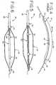
- a prior art balloon catheter 10is shown.
- a balloon catheter 10has a manifold 12 at the proximal end 9 of the catheter 10 with various ports 14, 16.
- the balloon catheter 10 that is shownhas one port 14 for the guidewire 118 and one port 16 for an inflation media as further described below.
- the manifold 12is attached to a proximal shaft 20 that extends toward the distal end 11 of the catheter 10.
- the proximal shaft 20may have two different lumens 22, 24 passing longitudinally through the proximal shaft 20.
- one lumen 22is for the guidewire 18 and the other lumen 24 is for the inflation media.
- the guidewire port 14 of the manifold 12opens to the guidewire lumen 22, and the inflation port 16 opens to the inflation lumen 24.
- the described manifold, ports and lumensare only one example of the type of structure that may be used with a balloon catheter and many other examples are possible as well.
- the proximal shaft 20may be bonded to an inner shaft 28.
- the term "bonded”simply refers to the boundary between two portions and is not meant to refer to a particular technique for adhering two members together.
- two shaftsmay be bonded together by gluing, heat welding, friction welding or the like.
- shaftsmay also be bonded together by extruding a shaft with two different portions having different shapes, material properties or other characteristics.
- two membersmay be attached in various other ways, including with intermediate members disposed therebetween.
- the inner shaft 28is smaller in diameter than the proximal shaft 20 and is shifted from the center axis of the proximal shaft 20 so that the guidewire lumen 22 of the proximal shaft 20 lines up with a matching guidewire lumen 22 extending through the inner shaft 28. Because the inner shaft 28 is smaller in diameter than the proximal shaft 20 and is shifted away from the inflation lumen 24, the inflation lumen 24 is exposed at the distal end 26 of the proximal shaft 20 to the interior of the balloon 30.
- the inner shaft 28extends to the distal end 11 of the catheter 10. Radiopaque bands 32 may be added to the inner shaft 28 to allow the physician to see the location of the balloon catheter 10 with visualization equipment during intraluminal procedures.
- the guidewire lumen 22 of the catheter 10opens at the distal end 11 of the catheter 10 to allow the catheter 10 to pass over a guidewire 18.
- the inner shaft 28is encompassed by a balloon 30, which may be used in angioplasty procedures or various other procedures.
- the proximal end 34 of the balloon 30is bonded to both the proximal shaft 20 and the inner shaft 28. However, the proximal end 34 could be bonded to only the proximal shaft 20 or the inner shaft 28 as desired.
- the distal end 36 of the balloon 30is bonded to the inner shaft 28.
- nylon-based materialssuch as polyether block amide (PEBA), which are biocompatible are preferred for most of the components.
- one problem that prior art balloon catheters 10 like the one described above may suffer fromis a tendency to curve when inflation pressure is applied to the balloon 30.
- current balloon catheters 10are rated for balloon pressures of approximately five to twenty atmospheres.
- the balloon 30 of some balloon catheters 10begins to curve as the pressure increases above about ten atmospheres.
- the balloon 30forms a curved shape when inflated under pressure, with an inner apex 38 and an outer apex 40 being formed approximately along the midpoint of the length of the balloon 30. Curving of the balloon 30 generally occurs because the balloon 30 seeks to expand both radially and longitudinally as inflation media is added to the interior of the balloon 30.
- the balloon 30compensates for the longitudinal expansion by curving or bending.
- the inner apex 38 of the curved balloon 30may contact the inner shaft 28 and may also bend the inner shaft 28 along the shape of the inner apex 38.
- the direction of balloon curvatureis not always predictable and may depend on various manufacturing or design characteristics and the orientation of the balloon 30 during intraluminal procedures. Although the amount of balloon curvature depends on the structure of the balloon catheter 10 and other factors, a balloon curvature of as much as 20 mm has been measured on certain models.
- One alternative for minimizing the amount of balloon curvature in a balloon catheteris to use an inner shaft with a portion made from a material with greater elasticity than conventional inner shafts. For example, it has been determined in tests that the maximum recommended Young's modulus for the inner shaft portion is about 586N/mm 2 (85 kpsi) or less when the double wall thickness of the balloon is about 0,076 mm (0.003"). As those in the art well-know, double wall thickness is a measurement of two thickness of the walls of a balloon folded adjacent each other in order to make taking measurements easier.
- the maximum recommended Young's modulus for an inner shaft portionis about 379 N/mm 2 (55 kpsi) or less when the double wall thickness of the balloon is about 0,064mm (0.0025"). Further, it has been determined that the maximum recommended Young's modulus for an inner shaft portion is about 172N/mm 2 (25 kpsi) or less when the double wall thickness of the balloon is about 0,051 mm(0.002").
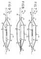
- a balloon catheter 42may have an inner shaft 44 bonded to the proximal shaft 20.
- the inner shaft 44has a greater elasticity than conventional inner shafts.
- the proximal shaft 20may have a Young's modulus higher than the inner shaft 44.
- the inner shaft 44extends from the proximal shaft 20 to the distal end 11 of the catheter 42.
- the guidewire lumen 22extends through the proximal shaft 20 and inner shaft 44.
- the distal end 36 of the balloon 30may be bonded to the inner shaft 44, and the proximal end 34 of the balloon 30 may be bonded to the proximal shaft 20 and the inner shaft 44 or the proximal shaft 20 alone.
- radiopaque bands 32may be added to the inner shaft 44.
- the inner shaft 44 as well as the inner shaft portions described beloware made from a biocompatible nylon-based material.
- a balloon catheter 46may have an inner shaft portion 48 bonded to the proximal shaft 20 and a distal shaft 50.
- the inner shaft portion 48has a greater elasticity than conventional inner shafts.
- the proximal shaft 20 and distal shaft 50may have a Young's modulus higher than the inner shaft portion 48.
- the inner shaft portion 48extends from the proximal shaft 20 to the distal shaft 50.
- the distal shaft 50is bonded to the inner shaft portion 48 and extends to the distal end 11 of the catheter 46.
- the guidewire lumen 22extends through the proximal shaft 20, inner shaft portion 48 and distal shaft 50.
- the distal end 36 of the balloon 30may be bonded to the distal shaft 50, and the proximal end 34 of the balloon 30 may be bonded to the proximal shaft 20 and the inner shaft portion 48 or the proximal shaft 20 alone. If desired, radiopaque bands 32 may be added to the inner shaft portion 48 and/or the distal shaft 50.
- a balloon catheter 52may have an inner shaft portion 54 bonded to a second proximal shaft portion 56 and a distal shaft 58.
- the second proximal shaft portion 56 and distal shaft 58may have a Young's modulus higher than the inner shaft portion 54.
- the proximal shaft 20may be made of a first proximal shaft portion 60 and a second proximal shaft portion 56.
- the first proximal shaft portion 60may have a larger diameter than the second proximal shaft portion 56 in order to expose the inflation lumen 24 to the interior of the balloon 30 as described above.
- the distal shaft 58extends to the distal end 11 of the catheter 52.
- the guidewire lumen 22extends through the first proximal shaft portion 60, second proximal shaft portion 56, inner shaft portion 54 and distal shaft 58.
- the distal end 36 of the balloon 30may be bonded to the distal shaft 58, and the proximal end 34 of the balloon 30 may be bonded to the first and second proximal shaft portions 60, 56 or to the first proximal shaft portion 60 alone.
- radiopaque bands 32may be added to the second proximal shaft portion 56 and the distal shaft 58.
- a balloon catheter 62may have an inner shaft portion 64 bonded to a second proximal shaft portion 66.
- the second proximal shaft portion 66may have a Young's modulus higher than the inner shaft portion 64.
- the inner shaft portion 64has a greater elasticity than conventional inner shafts.
- the proximal shaft 20may be made of a first proximal shaft portion 68 and a second proximal shaft portion 66.
- the first proximal shaft portion 68may have a larger diameter than the second proximal shaft portion 66 in order to expose the inflation lumen 24 to the interior of the balloon 30 as described above.
- the inner shaft portion 64extends to the distal end 11 of the catheter 62.
- the guidewire lumen 22extends through the first proximal shaft portion 68, second proximal shaft portion 66 and inner shaft portion 64.
- the distal end 36 of the balloon 30may be bonded to the inner shaft portion 64, and the proximal end 34 of the balloon 30 may be bonded to the first and second proximal shaft portions 68, 66. If desired radiopaque bands 32 may be added to the second proximal shaft portion 66 and/or the inner shaft portion 64.
- a balloon catheter 70may have an inner shaft portion 72 bonded to a second proximal shaft portion 74 and a distal shaft 76.
- the inner shaft portion 72may be made of a corrugated material.
- a corrugated materialmay be made with ridges that are folded against each other or with other constructions that are known.
- the corrugated materialis designed specifically to stretch in length when a longitudinal force is applied.
- the corrugated material of the inner shaft portion 72may stretch to minimize curving of the balloon 30 upon inflation.
- the second proximal shaft portion 74 and the distal shaft 76are made from non-corrugated materials that require significantly greater force to cause stretching.
- Corrugationsmay be integrally formed in a one-piece inner shaft so that a separate section of corrugated tubing is not required or a separate section of corrugated material may be used.
- the proximal shaft 20may be made of a first proximal shaft portion 78 and a second proximal shaft portion 74.
- the first proximal shaft portion 78may have a larger diameter than the second proximal shaft portion 74 in order to expose the inflation lumen 24 to the interior of the balloon 30 as described above.
- the distal shaft 76extends to the distal end 11 of the catheter 70.
- the guidewire lumen 22extends through the first proximal shaft portion 78, second proximal shaft portion 74, inner shaft portion 72 and distal shaft 76.
- the distal end 36 of the balloon 30may be bonded to the distal shaft 76, and the proximal end 34 of the balloon 30 may be bonded to the first and second proximal shaft portions 78, 74. If desired, radiopaque bands 32 may be added to the second proximal shaft portion 74 and the distal shaft 76.
- An inner shaft made from an elastic material or corrugated materialmay allow the length of the inner shaft to stretch when axial force is applied to the inner shaft.
- inflation mediafills the balloon and causes the balloon to expand longitudinally due to pressure
- the inner shaftstretches lengthwise to match the longitudinal expansion of the balloon.
- the inner shaftdoes not resist longitudinal expansion of the balloon like prior art balloon catheters. Therefore, the tendency of the balloon to curve as it is inflated may be eliminated or significantly minimized.
Landscapes
- Health & Medical Sciences (AREA)
- Life Sciences & Earth Sciences (AREA)
- Heart & Thoracic Surgery (AREA)
- Biomedical Technology (AREA)
- Biophysics (AREA)
- Pulmonology (AREA)
- Engineering & Computer Science (AREA)
- Anesthesiology (AREA)
- Hematology (AREA)
- Animal Behavior & Ethology (AREA)
- General Health & Medical Sciences (AREA)
- Public Health (AREA)
- Veterinary Medicine (AREA)
- Child & Adolescent Psychology (AREA)
- Media Introduction/Drainage Providing Device (AREA)
- Materials For Medical Uses (AREA)
Abstract
Description
- The present invention relates generally to intraluminal medical devices and more particularly to a balloon catheter that minimizes curving of the balloon during inflation thereof.
- Balloon catheters are widely used in the medical profession for various intraluminal procedures. One common procedure involving the use of a balloon catheter relates to angioplasty dilation of coronary or other arteries suffering from stenosis (i.e., a narrowing of the arterial lumen that restricts blood flow).
- Although balloon catheters are used in many other procedures as well, coronary angioplasty using a balloon catheter has drawn particular attention from the medical community because of the growing number of people suffering from heart problems associated with stenosis. This has lead to an increased demand for medical procedures to treat such problems. The widespread frequency of heart problems may be due to a number of societal changes, including the tendency of people to exercise less while eating greater quantities of unhealthy foods, in conjunction with the fact that people generally now have longer life spans than previous generations. Angioplasty procedures have become a popular alternative for treating coronary stenosis because angioplasty procedures are considerably less invasive than other alternatives. Traditionally, stenosis of the coronary arteries has been treated with bypass surgery. In general, bypass surgery involves splitting the chest bone to open the chest cavity and grafting a replacement vessel onto the heart to bypass the blocked, or stenosed, artery. However, coronary bypass surgery is a very invasive procedure that is risky and requires a long recovery time for the patient.
- To address the increased need for coronary artery treatments, the medical community has turned to angioplasty procedures, in combination with stenting procedures, to avoid the problems associated with traditional bypass surgery. Document
US 2003/0114911 discloses the features of the preambles ofclaims 1 and 18. Typically, angioplasty procedures are performed using a balloon-tipped catheter that may or may not have a stent mounted on the balloon (also referred to as a stented catheter). The physician performs the angioplasty procedure by introducing the balloon catheter into a peripheral artery (commonly one of the leg arteries) and threading the catheter to the narrowed part of the coronary artery to be treated. During this stage, the balloon is uninflated and collapsed onto the shaft of the catheter in order to present a low profile which may be passed through the arterial lumens. Once the balloon is positioned at the narrowed part of the artery, the balloon is expanded by pumping a mixture of saline and contrast solution through the catheter to the balloon. As a result, the balloon presses against the inner wall of the artery to dilate it. If a stent is mounted on the balloon, the balloon inflation also serves to expand the stent and implant it within the artery. After the artery is dilated, the balloon is deflated so that it once again collapses onto the shaft of the catheter. The balloon-tipped catheter is then retracted from the arteries. If a stent is used, the stent is left permanently implanted in its expanded state at the desired location in the artery to provide a support structure that prevents the artery from collapsing back to its pre-dilated condition. However, the above described example is only one use for balloon catheters, and many other uses are also possible. - One disadvantage of some current balloon catheters is that they may have a tendency to curve as the balloon is inflated. Accordingly, a balloon catheter that minimizes curving of the balloon during inflation would be desirable.
- Accordingly, a balloon catheter is described that minimizes the tendency of the balloon to curve as the balloon is expanded. In one embodiment, the balloon catheter has an inner shaft that is elastic. Thus, when the pressure of the inflation media inside the balloon is increased, the inner shaft may stretch longitudinally to accommodate longitudinal expansion of the balloon. As a result, the balloon tends to remain straight during inflation instead of curving. In another embodiment, the balloon catheter has an inner shaft with a corrugated portion. The corrugated portion allows the inner shaft to stretch during inflation of the balloon to minimize balloon curvature. Additional details are described below.
- The invention may be more fully understood by reading the following description in conjunction with the drawings, in which:
Figure 1 is a side elevational view of a prior art balloon catheter;Figure 2 is an enlarged cross-sectional view of the prior art balloon catheter shown inFigure 1 ;Figure 3 is an enlarged cross-sectional view of the prior art proximal shaft shown inFigure 1 ;Figure 4 is a side elevational view of the prior art balloon catheter shown inFigures 1 and 2 , showing the balloon curved due to inflation of the balloon;Figure 5 is an enlarged cross-sectional view of a balloon catheter, showing an inner shaft made from an elastic material to resist curving of the balloon during inflation;Figure 6 is an enlarged cross-sectional view of another balloon catheter, showing an inner shaft made from an elastic material attached to a distal shaft;Figure 7 is an enlarged cross-sectional view of another balloon catheter, showing an inner shaft made from an elastic material attached to a second proximal shaft portion and attached to a distal shaft;Figure 8 is an enlarged cross-sectional view of another balloon catheter, showing an inner shaft made from an elastic material attached to the distal end of the balloon; andFigure 9 is an enlarged cross-sectional view of another balloon catheter, showing a portion of the inner shaft made from a corrugated material to resist curving of the balloon during inflation.- Referring now to the drawings, and particularly to
Figures 1-4 , a priorart balloon catheter 10 is shown. Typically, aballoon catheter 10 has amanifold 12 at the proximal end 9 of thecatheter 10 withvarious ports balloon catheter 10 that is shown has oneport 14 for the guidewire 118 and oneport 16 for an inflation media as further described below. Themanifold 12 is attached to aproximal shaft 20 that extends toward thedistal end 11 of thecatheter 10. As shown inFigure 3 , theproximal shaft 20 may have twodifferent lumens proximal shaft 20. In the example shown, onelumen 22 is for theguidewire 18 and theother lumen 24 is for the inflation media. Thus, theguidewire port 14 of themanifold 12 opens to theguidewire lumen 22, and theinflation port 16 opens to theinflation lumen 24. The described manifold, ports and lumens, however, are only one example of the type of structure that may be used with a balloon catheter and many other examples are possible as well. - At the
distal end 26 of theproximal shaft 20, theproximal shaft 20 may be bonded to aninner shaft 28. As used herein, the term "bonded" simply refers to the boundary between two portions and is not meant to refer to a particular technique for adhering two members together. For example, two shafts may be bonded together by gluing, heat welding, friction welding or the like. However, shafts may also be bonded together by extruding a shaft with two different portions having different shapes, material properties or other characteristics. Furthermore, two members may be attached in various other ways, including with intermediate members disposed therebetween. As shown inFigure 2 , theinner shaft 28 is smaller in diameter than theproximal shaft 20 and is shifted from the center axis of theproximal shaft 20 so that theguidewire lumen 22 of theproximal shaft 20 lines up with amatching guidewire lumen 22 extending through theinner shaft 28. Because theinner shaft 28 is smaller in diameter than theproximal shaft 20 and is shifted away from theinflation lumen 24, theinflation lumen 24 is exposed at thedistal end 26 of theproximal shaft 20 to the interior of theballoon 30. - In the prior art embodiment shown in
Figures 1-4 , theinner shaft 28 extends to thedistal end 11 of thecatheter 10.Radiopaque bands 32 may be added to theinner shaft 28 to allow the physician to see the location of theballoon catheter 10 with visualization equipment during intraluminal procedures. Theguidewire lumen 22 of thecatheter 10 opens at thedistal end 11 of thecatheter 10 to allow thecatheter 10 to pass over aguidewire 18. Theinner shaft 28 is encompassed by aballoon 30, which may be used in angioplasty procedures or various other procedures. As shown, theproximal end 34 of theballoon 30 is bonded to both theproximal shaft 20 and theinner shaft 28. However, theproximal end 34 could be bonded to only theproximal shaft 20 or theinner shaft 28 as desired. Thedistal end 36 of theballoon 30 is bonded to theinner shaft 28. Although various materials may be used for theballoon catheter 10, nylon-based materials, such as polyether block amide (PEBA), which are biocompatible are preferred for most of the components. - As shown in
Figure 4 , one problem that priorart balloon catheters 10 like the one described above may suffer from is a tendency to curve when inflation pressure is applied to theballoon 30. Typically,current balloon catheters 10 are rated for balloon pressures of approximately five to twenty atmospheres. However, it has been found that theballoon 30 of someballoon catheters 10 begins to curve as the pressure increases above about ten atmospheres. As a result, theballoon 30 forms a curved shape when inflated under pressure, with aninner apex 38 and anouter apex 40 being formed approximately along the midpoint of the length of theballoon 30. Curving of theballoon 30 generally occurs because theballoon 30 seeks to expand both radially and longitudinally as inflation media is added to the interior of theballoon 30. Theinner shaft 28, however, resists longitudinal expansion of theballoon 30. As a result, theballoon 30 compensates for the longitudinal expansion by curving or bending. As shown inFigure 4 , theinner apex 38 of thecurved balloon 30 may contact theinner shaft 28 and may also bend theinner shaft 28 along the shape of theinner apex 38. The direction of balloon curvature is not always predictable and may depend on various manufacturing or design characteristics and the orientation of theballoon 30 during intraluminal procedures. Although the amount of balloon curvature depends on the structure of theballoon catheter 10 and other factors, a balloon curvature of as much as 20 mm has been measured on certain models. Generally, it appears that greater degrees of curvature are experienced withballoon catheters 10 having relatively thin-walled balloons 30 that are inflated to relatively high pressures. As described above, the resulting curvature of theballoon 30 when it is inflated may have significant risks that are undesirable. - One alternative for minimizing the amount of balloon curvature in a balloon catheter is to use an inner shaft with a portion made from a material with greater elasticity than conventional inner shafts. For example, it has been determined in tests that the maximum recommended Young's modulus for the inner shaft portion is about 586N/mm2 (85 kpsi) or less when the double wall thickness of the balloon is about 0,076 mm (0.003"). As those in the art well-know, double wall thickness is a measurement of two thickness of the walls of a balloon folded adjacent each other in order to make taking measurements easier. It has also been determined that the maximum recommended Young's modulus for an inner shaft portion is about 379 N/mm2 (55 kpsi) or less when the double wall thickness of the balloon is about 0,064mm (0.0025"). Further, it has been determined that the maximum recommended Young's modulus for an inner shaft portion is about 172N/mm2 (25 kpsi) or less when the double wall thickness of the balloon is about 0,051 mm(0.002"). Thus, it can now be seen from the described relationship that it may be desirable to decrease the Young's modulus of the inner shaft portion as the double wall thickness of the balloon is reduced. In each of these cases, it was determined that the resulting curvature of the balloon was minimal if the Young's modulus of the inner shaft portion is maintained at or below the recommended values for the particular balloons tested.
- Turning now to
Figure 5 , one embodiment of a balloon catheter 42 may have aninner shaft 44 bonded to theproximal shaft 20. As described above, theinner shaft 44 has a greater elasticity than conventional inner shafts. In contrast, theproximal shaft 20 may have a Young's modulus higher than theinner shaft 44. As shown, theinner shaft 44 extends from theproximal shaft 20 to thedistal end 11 of the catheter 42. Thus, theguidewire lumen 22 extends through theproximal shaft 20 andinner shaft 44. Thedistal end 36 of theballoon 30 may be bonded to theinner shaft 44, and theproximal end 34 of theballoon 30 may be bonded to theproximal shaft 20 and theinner shaft 44 or theproximal shaft 20 alone. If desired,radiopaque bands 32 may be added to theinner shaft 44. Preferably, theinner shaft 44 as well as the inner shaft portions described below are made from a biocompatible nylon-based material. - Turning now to
Figure 6 , another embodiment of aballoon catheter 46 may have aninner shaft portion 48 bonded to theproximal shaft 20 and adistal shaft 50. As described above, theinner shaft portion 48 has a greater elasticity than conventional inner shafts. In contrast, theproximal shaft 20 anddistal shaft 50 may have a Young's modulus higher than theinner shaft portion 48. As shown, theinner shaft portion 48 extends from theproximal shaft 20 to thedistal shaft 50. Thedistal shaft 50 is bonded to theinner shaft portion 48 and extends to thedistal end 11 of thecatheter 46. Thus, theguidewire lumen 22 extends through theproximal shaft 20,inner shaft portion 48 anddistal shaft 50. Thedistal end 36 of theballoon 30 may be bonded to thedistal shaft 50, and theproximal end 34 of theballoon 30 may be bonded to theproximal shaft 20 and theinner shaft portion 48 or theproximal shaft 20 alone. If desired,radiopaque bands 32 may be added to theinner shaft portion 48 and/or thedistal shaft 50. - Turning now to
Figure 7 , another embodiment of aballoon catheter 52 may have aninner shaft portion 54 bonded to a secondproximal shaft portion 56 and adistal shaft 58. In contrast, the secondproximal shaft portion 56 anddistal shaft 58 may have a Young's modulus higher than theinner shaft portion 54. As shown, theproximal shaft 20 may be made of a firstproximal shaft portion 60 and a secondproximal shaft portion 56. The firstproximal shaft portion 60 may have a larger diameter than the secondproximal shaft portion 56 in order to expose theinflation lumen 24 to the interior of theballoon 30 as described above. Thedistal shaft 58 extends to thedistal end 11 of thecatheter 52. Thus, theguidewire lumen 22 extends through the firstproximal shaft portion 60, secondproximal shaft portion 56,inner shaft portion 54 anddistal shaft 58. Thedistal end 36 of theballoon 30 may be bonded to thedistal shaft 58, and theproximal end 34 of theballoon 30 may be bonded to the first and secondproximal shaft portions proximal shaft portion 60 alone. If desired,radiopaque bands 32 may be added to the secondproximal shaft portion 56 and thedistal shaft 58. - Turning now to
Figure 8 , another embodiment of aballoon catheter 62 may have aninner shaft portion 64 bonded to a secondproximal shaft portion 66. In contrast, the secondproximal shaft portion 66 may have a Young's modulus higher than theinner shaft portion 64. As described above, theinner shaft portion 64 has a greater elasticity than conventional inner shafts. As shown, theproximal shaft 20 may be made of a firstproximal shaft portion 68 and a secondproximal shaft portion 66. The firstproximal shaft portion 68 may have a larger diameter than the secondproximal shaft portion 66 in order to expose theinflation lumen 24 to the interior of theballoon 30 as described above. Theinner shaft portion 64 extends to thedistal end 11 of thecatheter 62. Thus, theguidewire lumen 22 extends through the firstproximal shaft portion 68, secondproximal shaft portion 66 andinner shaft portion 64. Thedistal end 36 of theballoon 30 may be bonded to theinner shaft portion 64, and theproximal end 34 of theballoon 30 may be bonded to the first and secondproximal shaft portions radiopaque bands 32 may be added to the secondproximal shaft portion 66 and/or theinner shaft portion 64. - Turning now to
Figure 9 , another embodiment of aballoon catheter 70 may have aninner shaft portion 72 bonded to a secondproximal shaft portion 74 and adistal shaft 76. In this embodiment, theinner shaft portion 72 may be made of a corrugated material. A corrugated material may be made with ridges that are folded against each other or with other constructions that are known. Thus, the corrugated material is designed specifically to stretch in length when a longitudinal force is applied. As a result, the corrugated material of theinner shaft portion 72 may stretch to minimize curving of theballoon 30 upon inflation. In contrast, the secondproximal shaft portion 74 and thedistal shaft 76 are made from non-corrugated materials that require significantly greater force to cause stretching. Corrugations may be integrally formed in a one-piece inner shaft so that a separate section of corrugated tubing is not required or a separate section of corrugated material may be used. As shown, theproximal shaft 20 may be made of a firstproximal shaft portion 78 and a secondproximal shaft portion 74. The firstproximal shaft portion 78 may have a larger diameter than the secondproximal shaft portion 74 in order to expose theinflation lumen 24 to the interior of theballoon 30 as described above. Thedistal shaft 76 extends to thedistal end 11 of thecatheter 70. Thus, theguidewire lumen 22 extends through the firstproximal shaft portion 78, secondproximal shaft portion 74,inner shaft portion 72 anddistal shaft 76. Thedistal end 36 of theballoon 30 may be bonded to thedistal shaft 76, and theproximal end 34 of theballoon 30 may be bonded to the first and secondproximal shaft portions radiopaque bands 32 may be added to the secondproximal shaft portion 74 and thedistal shaft 76. - The advantages of the invention are now apparent. An inner shaft made from an elastic material or corrugated material may allow the length of the inner shaft to stretch when axial force is applied to the inner shaft. Thus, when inflation media fills the balloon and causes the balloon to expand longitudinally due to pressure, the inner shaft stretches lengthwise to match the longitudinal expansion of the balloon. As a result, the inner shaft does not resist longitudinal expansion of the balloon like prior art balloon catheters. Therefore, the tendency of the balloon to curve as it is inflated may be eliminated or significantly minimized.
- While preferred embodiments of the invention have been described, it should be understood that the invention is not so limited, and modifications may be made without departing from the invention. The scope of the invention is defined by the appended claims, and all devices that come within the meaning of the claims, either literally or by equivalence, are intended to be embraced therein.
Claims (22)
- A balloon catheter (42,46,52,62,70) for intraluminal medical treatment, comprising:a catheter comprising a proximal shaft portion (20) and an inner shaft portion (44,48,54) attached to said proximal shaft portion, said inner shaft portion being disposed distal from said proximal shaft portion, wherein a first lumen extends through at least part of said proximal shaft portion and a second lumen extends through at least said proximal shaft portion and said inner shaft portion;a balloon (30) comprising a proximal end (34) and a distal end (36) said proximal end and said distal end being attached to said catheter, said balloon thereby encompassing at least a part of said inner shaft portion between said proximal end and said distal end, and said first lumen being exposed to an interior of said balloon;wherein said balloon is collapsible onto said catheter to facilitate intraluminal insertion of said balloon and said catheter into a body cavity, said catheter being threadable through a body lumen by extending a guidewire through said second lumen, said balloon thereby being inflatable to dilate said body cavity by passing an inflation media through said first lumen into said interior of said balloon; andcharacterised in that
a double wall thickness of said balloon is about 0,076mm (0.003") or less and said inner shaft portion is made from an elastic material with a Young's modulus of about 586 N/mm2 (85 kpsi) or less, said elastic material thereby permitting said inner shaft portion to stretch as said balloon is inflated to minimize curving of said balloon due to a pressure of said inflation media. - The balloon catheter according to claim 1, wherein said double wall thickness of said balloon is about 0,064mm (0.0025") or less and said elastic material has a Young's modulus of about 379 N/mm2 (55 kpsi) or less.
- The balloon catheter according to claim 2, wherein said double wall thickness of said balloon is about 0,051 mm (0.002") or less and said elastic material has a Young's modulus of about 172 N/mm2 (25 kpsi) or less.
- The balloon catheter according to claim 1, wherein said inner shaft portion is smaller in diameter than said proximal shaft portion, said inner shaft portion being bonded to only part of a cross-sectional area of said proximal shaft portion, said first lumen opening at an unexposed part of said cross-sectional area and thereby being exposed to said interior of said balloon.
- The balloon catheter according to claim 1, wherein said proximal shaft portion, said inner shaft portion and said balloon are made from a biocompatible nylon-based material.
- The balloon catheter according to claim 1, wherein at least two radiopaque markers (32) are attached to said inner shaft portion.
- The balloon catheter according to claim 1, wherein said inner shaft portion is bonded to said proximal shaft portion and said distal end of said balloon is attached to said inner shaft portion.
- The balloon catheter according to claim 7, wherein said inner shaft portion extends to a catheter distal end.
- The balloon catheter according to claim 8, wherein said proximal end of said balloon is attached to at least part of said proximal shaft portion.
- The balloon catheter according to claim 1, further comprising a distal shaft portion (50,58) attached to said inner shaft portion, said distal shaft portion being disposed distal from said inner shaft portion and said second lumen extending through said distal shaft portion, wherein said distal end of said balloon is attached to said distal shaft portion, said distal shaft portion being made from a material with a Young's modulus higher than said inner shaft portion.
- The balloon catheter according to claim 10, wherein said proximal end of said balloon is attached to at least part of said proximal shaft portion.
- The balloon catheter according to claim 1, wherein said proximal shaft portion comprises a first proximal shaft portion (60,68,78) and a second proximal shaft portion (56,66,74), said balloon encompassing at least a part of said second proximal shaft portion between said proximal end and said distal end, and said second proximal shaft portion being attached to said inner shaft portion, said inner shaft portion being disposed distal from said second proximal shaft portion, wherein said second proximal shaft portion is made from a material with a Young's modulus higher than said inner shaft portion.
- The balloon catheter according to claim 12, further comprising a distal shaft portion attached to said inner shaft portion, said distal shaft portion being disposed distal from said inner shaft portion and said second lumen extending through said distal shaft portion, wherein said distal end of said balloon is attached to said distal shaft portion, said distal shaft portion being made from a material with a Young's modulus higher than said inner shaft portion.
- The balloon catheter according to claim 13, wherein said first proximal shaft portion is larger in diameter than said second proximal shaft portion, said proximal end of said balloon being attached to at least part of said first proximal shaft portion.
- The balloon catheter according to claim 1, wherein said distal end of said balloon is attached to said inner shaft portion.
- The balloon catheter according to claim 15, wherein said proximal shaft portion comprises a first proximal shaft portion and a second proximal shaft portion, said balloon encompassing at least a part of said second proximal shaft portion between said proximal end and said distal end, and said second proximal shaft portion being attached to said inner shaft portion, said inner shaft portion being disposed distal from said second proximal shaft portion, wherein said second proximal shaft portion is made from a material with a Young's modulus higher than said inner shaft portion.
- The balloon catheter according to claim 16, wherein said first proximal shaft portion is larger in diameter than said second proximal shaft portion, said proximal end of said balloon being attached to at least part of said first proximal shaft portion, and said inner shaft portion extends to a catheter distal end.
- A balloon catheter (42,46,52,62,70) for intraluminal medical treatment, comprising:a catheter comprising a proximal shaft portion and an inner shaft portion attached to said proximal shaft portion, said inner shaft portion being disposed distal from said proximal shaft portion, wherein a first lumen extends through at least part of said proximal shaft portion and a second lumen extends through at least said proximal shaft portion and said inner shaft portion;a balloon (30) comprising a proximal end and a distal end, said proximal end and said distal end being attached to said catheter, said balloon thereby encompassing at least a part of said inner shaft portion between said proximal end and said distal end, and said first lumen being exposed to an interior of said balloon;wherein said balloon is collapsible onto said catheter to facilitate intraluminal insertion of said balloon and said catheter into a body cavity, said catheter being threadable through a body lumen by extending a guidewire through said second lumen, said balloon thereby being inflatable to dilate said body cavity by passing an inflation media through said first lumen into said interior of said balloon; andcharacterised in that
the inner shaft portion (20) has a reduced resistance to axial extension such that on inflation of the balloon, the inner shaft portion extends axially to match the axial extension of the balloon such that the inner shaft portion imparts substantially zero bending moment on the inflated balloon. - The balloon catheter according to claim 18, wherein said inner shaft portion is made from a corrugated material.
- The balloon catheter according to claim 18 or 19, wherein the proximal end of the balloon is attached to the proximal shaft portion of the catheter and the distal end of the balloon is attached to the inner shaft portion of the catheter.
- The balloon catheter according to claims 18 to 20, further comprising a distal shaft portion attached to said inner shaft portion, said distal shaft portion being disposed distal from said inner shaft portion and said second lumen extending through said distal shaft portion, wherein said distal end of said balloon is attached to said distal shaft portion, said distal shaft portion being made from a non-corrugated material.
- The balloon catheter according to claim 21, wherein said proximal shaft portion comprises a first proximal shaft portion and a second proximal shaft portion, said first proximal shaft portion being larger in diameter than said second proximal shaft portion and said proximal end of said balloon being attached to at least part of said first proximal shaft portion, wherein said balloon encompasses at least a part of said second proximal shaft portion between said proximal end and said distal end, said second proximal shaft portion being attached to said inner shaft portion, and said inner shaft portion being disposed distal from said second proximal shaft portion, wherein said second proximal shaft portion is made from a non-corrugated material.
Applications Claiming Priority (2)
| Application Number | Priority Date | Filing Date | Title |
|---|---|---|---|
| US68945105P | 2005-06-10 | 2005-06-10 | |
| PCT/US2006/022504WO2006135759A1 (en) | 2005-06-10 | 2006-06-09 | Balloon catheter that resists curving |
Publications (2)
| Publication Number | Publication Date |
|---|---|
| EP1896110A1 EP1896110A1 (en) | 2008-03-12 |
| EP1896110B1true EP1896110B1 (en) | 2009-10-21 |
Family
ID=37012128
Family Applications (1)
| Application Number | Title | Priority Date | Filing Date |
|---|---|---|---|
| EP06772709ANot-in-forceEP1896110B1 (en) | 2005-06-10 | 2006-06-09 | Balloon catheter that resists curving |
Country Status (6)
| Country | Link |
|---|---|
| US (1) | US8292912B2 (en) |
| EP (1) | EP1896110B1 (en) |
| JP (1) | JP5047166B2 (en) |
| AT (1) | ATE446120T1 (en) |
| DE (1) | DE602006009930D1 (en) |
| WO (1) | WO2006135759A1 (en) |
Cited By (1)
| Publication number | Priority date | Publication date | Assignee | Title |
|---|---|---|---|---|
| WO2011080778A1 (en) | 2009-12-30 | 2011-07-07 | Invatec S.P.A. | Catheter for intraluminal treatment, method for making the same and apparatus for making a tool |
Families Citing this family (23)
| Publication number | Priority date | Publication date | Assignee | Title |
|---|---|---|---|---|
| PL2124831T3 (en) | 2007-03-15 | 2017-03-31 | Ortho-Space Ltd. | Prosthetic devices |
| US20080306427A1 (en)* | 2007-06-05 | 2008-12-11 | Cook Incorporated | Chronic Hemodialysis Catheter with Balloon |
| US8182446B2 (en) | 2007-09-12 | 2012-05-22 | Cook Medical Technologies | Balloon catheter for delivering a therapeutic agent |
| US8034022B2 (en) | 2008-04-08 | 2011-10-11 | Cook Medical Technologies Llc | Weeping balloon catheter |
| JP2010035660A (en)* | 2008-07-31 | 2010-02-18 | Kaneka Corp | Balloon catheter and stent delivery catheter for medical use |
| GB201113807D0 (en)* | 2011-08-10 | 2011-09-21 | Isis Innovation | Determining torque in a shaft |
| US9730726B2 (en) | 2011-10-07 | 2017-08-15 | W. L. Gore & Associates, Inc. | Balloon assemblies having controllably variable topographies |
| US9289307B2 (en) | 2011-10-18 | 2016-03-22 | Ortho-Space Ltd. | Prosthetic devices and methods for using same |
| CN107281617A (en)* | 2012-03-09 | 2017-10-24 | 明讯科技有限公司 | Foley's tube with expandable axle |
| KR20140133548A (en)* | 2012-03-09 | 2014-11-19 | 클리어스트림 테크놀러지스 리미티드 | Medical balloon with multi-position actuator for precisely arranging the working surface |
| IN2014DN07123A (en) | 2012-03-09 | 2015-04-24 | Clearstream Tech Ltd | |
| JP6220355B2 (en) | 2012-03-09 | 2017-10-25 | クリアストリーム・テクノロジーズ・リミテッド | Medical balloon with a radiopaque end portion for accurately identifying the location of the working surface |
| US10500378B2 (en) | 2012-03-09 | 2019-12-10 | Clearstream Technologies Limited | Medical balloon including radiopaque insert for precisely identifying a working surface location |
| EP2938387B1 (en)* | 2012-12-31 | 2021-12-08 | C.R. Bard Inc. | Balloon catheter with adjustable inner member |
| US9669194B2 (en) | 2013-03-14 | 2017-06-06 | W. L. Gore & Associates, Inc. | Conformable balloon devices and methods |
| DE102013104029A1 (en) | 2013-04-22 | 2014-10-23 | Innora Gmbh | balloon catheter |
| US10729570B2 (en) | 2013-09-17 | 2020-08-04 | West Coast Catheter, Inc. | Medical balloon with varied compliance |
| US10286190B2 (en) | 2013-12-11 | 2019-05-14 | Cook Medical Technologies Llc | Balloon catheter with dynamic vessel engaging member |
| EP2898920B1 (en) | 2014-01-24 | 2018-06-06 | Cook Medical Technologies LLC | Articulating balloon catheter |
| JP6442229B2 (en)* | 2014-10-30 | 2018-12-19 | 株式会社グッドマン | Balloon catheter |
| US10499892B2 (en)* | 2015-08-11 | 2019-12-10 | The Spectranetics Corporation | Temporary occlusion balloon devices and methods for preventing blood flow through a vascular perforation |
| WO2017046647A1 (en) | 2015-09-18 | 2017-03-23 | Ortho-Space Ltd. | Intramedullary fixated subacromial spacers |
| EP3573806A4 (en) | 2017-01-30 | 2019-12-11 | Ortho-Space Ltd. | Processing machine and methods for processing dip-molded articles |
Family Cites Families (10)
| Publication number | Priority date | Publication date | Assignee | Title |
|---|---|---|---|---|
| US4998923A (en) | 1988-08-11 | 1991-03-12 | Advanced Cardiovascular Systems, Inc. | Steerable dilatation catheter |
| US5171221A (en) | 1991-02-05 | 1992-12-15 | Target Therapeutics | Single lumen low profile valved balloon catheter |
| US6027863A (en)* | 1991-09-05 | 2000-02-22 | Intratherapeutics, Inc. | Method for manufacturing a tubular medical device |
| JP3970341B2 (en)* | 1994-06-20 | 2007-09-05 | テルモ株式会社 | Vascular catheter |
| US5549552A (en)* | 1995-03-02 | 1996-08-27 | Scimed Life Systems, Inc. | Balloon dilation catheter with improved pushability, trackability and crossability |
| DE69828429T2 (en)* | 1997-10-08 | 2005-12-08 | Kaneka Corp. | BALLOON CATHETER AND MANUFACTURING METHOD THEREFOR |
| US6066157A (en)* | 1998-09-16 | 2000-05-23 | Medtronics Ave, Inc. | Anchor joint for coaxial balloon dilatation catheter |
| GB2372211B (en)* | 2001-02-19 | 2005-04-20 | Biocompatibles Ltd | A catheter |
| US20040236366A1 (en)* | 2002-05-16 | 2004-11-25 | Kennedy Kenneth C. | Non-buckling balloon catheter |
| EP1948288B1 (en)* | 2005-11-14 | 2009-12-23 | Abbott Laboratories Vascular Enterprises Limited | Balloon catheter with elastic segment |
- 2006
- 2006-06-09EPEP06772709Apatent/EP1896110B1/ennot_activeNot-in-force
- 2006-06-09WOPCT/US2006/022504patent/WO2006135759A1/enactiveApplication Filing
- 2006-06-09ATAT06772709Tpatent/ATE446120T1/ennot_activeIP Right Cessation
- 2006-06-09DEDE602006009930Tpatent/DE602006009930D1/enactiveActive
- 2006-06-09USUS11/450,912patent/US8292912B2/ennot_activeExpired - Fee Related
- 2006-06-09JPJP2008515975Apatent/JP5047166B2/ennot_activeExpired - Fee Related
Cited By (1)
| Publication number | Priority date | Publication date | Assignee | Title |
|---|---|---|---|---|
| WO2011080778A1 (en) | 2009-12-30 | 2011-07-07 | Invatec S.P.A. | Catheter for intraluminal treatment, method for making the same and apparatus for making a tool |
Also Published As
| Publication number | Publication date |
|---|---|
| JP5047166B2 (en) | 2012-10-10 |
| DE602006009930D1 (en) | 2009-12-03 |
| JP2008543380A (en) | 2008-12-04 |
| US8292912B2 (en) | 2012-10-23 |
| ATE446120T1 (en) | 2009-11-15 |
| EP1896110A1 (en) | 2008-03-12 |
| WO2006135759A1 (en) | 2006-12-21 |
| US20060287665A1 (en) | 2006-12-21 |
Similar Documents
| Publication | Publication Date | Title |
|---|---|---|
| EP1896110B1 (en) | Balloon catheter that resists curving | |
| US7708753B2 (en) | Balloon catheter with extendable dilation wire | |
| US9192747B2 (en) | Balloon catheter with dilating elements | |
| JP3713048B2 (en) | Catheter with reinforced oval cross section | |
| US5573508A (en) | Catheter with an expandable perfusion lumen | |
| US7022106B2 (en) | Catheter having enhanced distal pushability | |
| AU609431B2 (en) | Method and apparatus for treating hypertrophy of the prostate gland | |
| US6270522B1 (en) | High pressure catheter balloon | |
| US20100010521A1 (en) | Cutting balloon with movable member | |
| US9937331B2 (en) | Integral dilation element for a balloon catheter | |
| WO2006107919A1 (en) | Catheter device with varying flexibility | |
| US8585959B2 (en) | Balloon with integrally retained dilation element | |
| US20070276427A1 (en) | Torquable balloon catheters and methods | |
| JP2005021684A (en) | Balloon catheter equipped with automatic centering tip | |
| EP1518582B1 (en) | Rapid-exchange balloon catheter with hypotube shaft | |
| US7708931B2 (en) | Balloon catheter | |
| JP2005524418A (en) | Eccentric catheter shaft | |
| EP1732632A1 (en) | Medical balloon with enlarged transitional radii | |
| KR20020059901A (en) | Stepwise Extendable Balloon | |
| EP2599516B1 (en) | Improved integral dilation element for a balloon catheter | |
| JP2006122551A (en) | Catheter | |
| JP2024514212A (en) | Systems, devices and methods for forming lumens | |
| JPH07532A (en) | Catheter with conduit type balloon |
Legal Events
| Date | Code | Title | Description |
|---|---|---|---|
| PUAI | Public reference made under article 153(3) epc to a published international application that has entered the european phase | Free format text:ORIGINAL CODE: 0009012 | |
| 17P | Request for examination filed | Effective date:20071219 | |
| AK | Designated contracting states | Kind code of ref document:A1 Designated state(s):AT BE BG CH CY CZ DE DK EE ES FI FR GB GR HU IE IS IT LI LT LU LV MC NL PL PT RO SE SI SK TR | |
| DAX | Request for extension of the european patent (deleted) | ||
| DAX | Request for extension of the european patent (deleted) | ||
| GRAP | Despatch of communication of intention to grant a patent | Free format text:ORIGINAL CODE: EPIDOSNIGR1 | |
| GRAS | Grant fee paid | Free format text:ORIGINAL CODE: EPIDOSNIGR3 | |
| GRAA | (expected) grant | Free format text:ORIGINAL CODE: 0009210 | |
| AK | Designated contracting states | Kind code of ref document:B1 Designated state(s):AT BE BG CH CY CZ DE DK EE ES FI FR GB GR HU IE IS IT LI LT LU LV MC NL PL PT RO SE SI SK TR | |
| REG | Reference to a national code | Ref country code:GB Ref legal event code:FG4D | |
| REG | Reference to a national code | Ref country code:CH Ref legal event code:EP | |
| REG | Reference to a national code | Ref country code:IE Ref legal event code:FG4D | |
| REF | Corresponds to: | Ref document number:602006009930 Country of ref document:DE Date of ref document:20091203 Kind code of ref document:P | |
| LTIE | Lt: invalidation of european patent or patent extension | Effective date:20091021 | |
| NLV1 | Nl: lapsed or annulled due to failure to fulfill the requirements of art. 29p and 29m of the patents act | ||
| PG25 | Lapsed in a contracting state [announced via postgrant information from national office to epo] | Ref country code:LT Free format text:LAPSE BECAUSE OF FAILURE TO SUBMIT A TRANSLATION OF THE DESCRIPTION OR TO PAY THE FEE WITHIN THE PRESCRIBED TIME-LIMIT Effective date:20091021 Ref country code:SE Free format text:LAPSE BECAUSE OF FAILURE TO SUBMIT A TRANSLATION OF THE DESCRIPTION OR TO PAY THE FEE WITHIN THE PRESCRIBED TIME-LIMIT Effective date:20091021 Ref country code:IS Free format text:LAPSE BECAUSE OF FAILURE TO SUBMIT A TRANSLATION OF THE DESCRIPTION OR TO PAY THE FEE WITHIN THE PRESCRIBED TIME-LIMIT Effective date:20100221 Ref country code:PT Free format text:LAPSE BECAUSE OF FAILURE TO SUBMIT A TRANSLATION OF THE DESCRIPTION OR TO PAY THE FEE WITHIN THE PRESCRIBED TIME-LIMIT Effective date:20100222 Ref country code:ES Free format text:LAPSE BECAUSE OF FAILURE TO SUBMIT A TRANSLATION OF THE DESCRIPTION OR TO PAY THE FEE WITHIN THE PRESCRIBED TIME-LIMIT Effective date:20100201 Ref country code:FI Free format text:LAPSE BECAUSE OF FAILURE TO SUBMIT A TRANSLATION OF THE DESCRIPTION OR TO PAY THE FEE WITHIN THE PRESCRIBED TIME-LIMIT Effective date:20091021 | |
| PG25 | Lapsed in a contracting state [announced via postgrant information from national office to epo] | Ref country code:SI Free format text:LAPSE BECAUSE OF FAILURE TO SUBMIT A TRANSLATION OF THE DESCRIPTION OR TO PAY THE FEE WITHIN THE PRESCRIBED TIME-LIMIT Effective date:20091021 Ref country code:CY Free format text:LAPSE BECAUSE OF FAILURE TO SUBMIT A TRANSLATION OF THE DESCRIPTION OR TO PAY THE FEE WITHIN THE PRESCRIBED TIME-LIMIT Effective date:20091021 Ref country code:PL Free format text:LAPSE BECAUSE OF FAILURE TO SUBMIT A TRANSLATION OF THE DESCRIPTION OR TO PAY THE FEE WITHIN THE PRESCRIBED TIME-LIMIT Effective date:20091021 Ref country code:LV Free format text:LAPSE BECAUSE OF FAILURE TO SUBMIT A TRANSLATION OF THE DESCRIPTION OR TO PAY THE FEE WITHIN THE PRESCRIBED TIME-LIMIT Effective date:20091021 | |
| PG25 | Lapsed in a contracting state [announced via postgrant information from national office to epo] | Ref country code:BE Free format text:LAPSE BECAUSE OF FAILURE TO SUBMIT A TRANSLATION OF THE DESCRIPTION OR TO PAY THE FEE WITHIN THE PRESCRIBED TIME-LIMIT Effective date:20091021 Ref country code:AT Free format text:LAPSE BECAUSE OF FAILURE TO SUBMIT A TRANSLATION OF THE DESCRIPTION OR TO PAY THE FEE WITHIN THE PRESCRIBED TIME-LIMIT Effective date:20091021 | |
| PG25 | Lapsed in a contracting state [announced via postgrant information from national office to epo] | Ref country code:RO Free format text:LAPSE BECAUSE OF FAILURE TO SUBMIT A TRANSLATION OF THE DESCRIPTION OR TO PAY THE FEE WITHIN THE PRESCRIBED TIME-LIMIT Effective date:20091021 Ref country code:EE Free format text:LAPSE BECAUSE OF FAILURE TO SUBMIT A TRANSLATION OF THE DESCRIPTION OR TO PAY THE FEE WITHIN THE PRESCRIBED TIME-LIMIT Effective date:20091021 Ref country code:DK Free format text:LAPSE BECAUSE OF FAILURE TO SUBMIT A TRANSLATION OF THE DESCRIPTION OR TO PAY THE FEE WITHIN THE PRESCRIBED TIME-LIMIT Effective date:20091021 Ref country code:BG Free format text:LAPSE BECAUSE OF FAILURE TO SUBMIT A TRANSLATION OF THE DESCRIPTION OR TO PAY THE FEE WITHIN THE PRESCRIBED TIME-LIMIT Effective date:20100121 | |
| PLBE | No opposition filed within time limit | Free format text:ORIGINAL CODE: 0009261 | |
| STAA | Information on the status of an ep patent application or granted ep patent | Free format text:STATUS: NO OPPOSITION FILED WITHIN TIME LIMIT | |
| PG25 | Lapsed in a contracting state [announced via postgrant information from national office to epo] | Ref country code:SK Free format text:LAPSE BECAUSE OF FAILURE TO SUBMIT A TRANSLATION OF THE DESCRIPTION OR TO PAY THE FEE WITHIN THE PRESCRIBED TIME-LIMIT Effective date:20091021 Ref country code:CZ Free format text:LAPSE BECAUSE OF FAILURE TO SUBMIT A TRANSLATION OF THE DESCRIPTION OR TO PAY THE FEE WITHIN THE PRESCRIBED TIME-LIMIT Effective date:20091021 | |
| 26N | No opposition filed | Effective date:20100722 | |
| PG25 | Lapsed in a contracting state [announced via postgrant information from national office to epo] | Ref country code:GR Free format text:LAPSE BECAUSE OF FAILURE TO SUBMIT A TRANSLATION OF THE DESCRIPTION OR TO PAY THE FEE WITHIN THE PRESCRIBED TIME-LIMIT Effective date:20100122 | |
| PG25 | Lapsed in a contracting state [announced via postgrant information from national office to epo] | Ref country code:MC Free format text:LAPSE BECAUSE OF NON-PAYMENT OF DUE FEES Effective date:20100630 | |
| REG | Reference to a national code | Ref country code:CH Ref legal event code:PL | |
| REG | Reference to a national code | Ref country code:FR Ref legal event code:ST Effective date:20110228 | |
| PG25 | Lapsed in a contracting state [announced via postgrant information from national office to epo] | Ref country code:IT Free format text:LAPSE BECAUSE OF FAILURE TO SUBMIT A TRANSLATION OF THE DESCRIPTION OR TO PAY THE FEE WITHIN THE PRESCRIBED TIME-LIMIT Effective date:20091021 | |
| PG25 | Lapsed in a contracting state [announced via postgrant information from national office to epo] | Ref country code:LI Free format text:LAPSE BECAUSE OF NON-PAYMENT OF DUE FEES Effective date:20100630 Ref country code:CH Free format text:LAPSE BECAUSE OF NON-PAYMENT OF DUE FEES Effective date:20100630 | |
| PG25 | Lapsed in a contracting state [announced via postgrant information from national office to epo] | Ref country code:FR Free format text:LAPSE BECAUSE OF NON-PAYMENT OF DUE FEES Effective date:20100630 | |
| REG | Reference to a national code | Ref country code:GB Ref legal event code:732E Free format text:REGISTERED BETWEEN 20110804 AND 20110810 | |
| PG25 | Lapsed in a contracting state [announced via postgrant information from national office to epo] | Ref country code:LU Free format text:LAPSE BECAUSE OF NON-PAYMENT OF DUE FEES Effective date:20100609 Ref country code:NL Free format text:LAPSE BECAUSE OF FAILURE TO SUBMIT A TRANSLATION OF THE DESCRIPTION OR TO PAY THE FEE WITHIN THE PRESCRIBED TIME-LIMIT Effective date:20091021 Ref country code:HU Free format text:LAPSE BECAUSE OF FAILURE TO SUBMIT A TRANSLATION OF THE DESCRIPTION OR TO PAY THE FEE WITHIN THE PRESCRIBED TIME-LIMIT Effective date:20100422 | |
| PG25 | Lapsed in a contracting state [announced via postgrant information from national office to epo] | Ref country code:TR Free format text:LAPSE BECAUSE OF FAILURE TO SUBMIT A TRANSLATION OF THE DESCRIPTION OR TO PAY THE FEE WITHIN THE PRESCRIBED TIME-LIMIT Effective date:20091021 | |
| P01 | Opt-out of the competence of the unified patent court (upc) registered | Effective date:20230602 | |
| PGFP | Annual fee paid to national office [announced via postgrant information from national office to epo] | Ref country code:IE Payment date:20230526 Year of fee payment:18 Ref country code:DE Payment date:20230509 Year of fee payment:18 | |
| PGFP | Annual fee paid to national office [announced via postgrant information from national office to epo] | Ref country code:GB Payment date:20230510 Year of fee payment:18 | |
| REG | Reference to a national code | Ref country code:DE Ref legal event code:R081 Ref document number:602006009930 Country of ref document:DE Owner name:COOK MEDICAL TECHNOLOGIES, LLC, BLOOMINGTON, US Free format text:FORMER OWNER: COOK INC., BLOOMINGTON, IND., US | |
| REG | Reference to a national code | Ref country code:DE Ref legal event code:R119 Ref document number:602006009930 Country of ref document:DE | |
| GBPC | Gb: european patent ceased through non-payment of renewal fee | Effective date:20240609 | |
| PG25 | Lapsed in a contracting state [announced via postgrant information from national office to epo] | Ref country code:DE Free format text:LAPSE BECAUSE OF NON-PAYMENT OF DUE FEES Effective date:20250101 | |
| PG25 | Lapsed in a contracting state [announced via postgrant information from national office to epo] | Ref country code:IE Free format text:LAPSE BECAUSE OF NON-PAYMENT OF DUE FEES Effective date:20240609 | |
| PG25 | Lapsed in a contracting state [announced via postgrant information from national office to epo] | Ref country code:GB Free format text:LAPSE BECAUSE OF NON-PAYMENT OF DUE FEES Effective date:20240609 |