EP1892804B1 - Distributor for connecting actuators and/or sensors - Google Patents
Distributor for connecting actuators and/or sensorsDownload PDFInfo
- Publication number
- EP1892804B1 EP1892804B1EP07123155AEP07123155AEP1892804B1EP 1892804 B1EP1892804 B1EP 1892804B1EP 07123155 AEP07123155 AEP 07123155AEP 07123155 AEP07123155 AEP 07123155AEP 1892804 B1EP1892804 B1EP 1892804B1
- Authority
- EP
- European Patent Office
- Prior art keywords
- component
- distributor
- sensors
- actuators
- cable
- Prior art date
- Legal status (The legal status is an assumption and is not a legal conclusion. Google has not performed a legal analysis and makes no representation as to the accuracy of the status listed.)
- Expired - Lifetime
Links
- 238000007789sealingMethods0.000claimsdescription3
- 150000001875compoundsChemical class0.000claimsdescription2
- 238000009413insulationMethods0.000claimsdescription2
- 230000000149penetrating effectEffects0.000claimsdescription2
- 239000004020conductorSubstances0.000abstractdescription3
- 238000009434installationMethods0.000description4
- 230000007935neutral effectEffects0.000description3
- 229940125898compound 5Drugs0.000description1
- 238000010276constructionMethods0.000description1
- 230000001419dependent effectEffects0.000description1
- 238000009415formworkMethods0.000description1
- 238000003780insertionMethods0.000description1
- 230000037431insertionEffects0.000description1
- 238000004382pottingMethods0.000description1
- 230000002441reversible effectEffects0.000description1
Images
Classifications
- H—ELECTRICITY
- H01—ELECTRIC ELEMENTS
- H01R—ELECTRICALLY-CONDUCTIVE CONNECTIONS; STRUCTURAL ASSOCIATIONS OF A PLURALITY OF MUTUALLY-INSULATED ELECTRICAL CONNECTING ELEMENTS; COUPLING DEVICES; CURRENT COLLECTORS
- H01R12/00—Structural associations of a plurality of mutually-insulated electrical connecting elements, specially adapted for printed circuits, e.g. printed circuit boards [PCB], flat or ribbon cables, or like generally planar structures, e.g. terminal strips, terminal blocks; Coupling devices specially adapted for printed circuits, flat or ribbon cables, or like generally planar structures; Terminals specially adapted for contact with, or insertion into, printed circuits, flat or ribbon cables, or like generally planar structures
- H01R12/50—Fixed connections
- H01R12/59—Fixed connections for flexible printed circuits, flat or ribbon cables or like structures
- H01R12/65—Fixed connections for flexible printed circuits, flat or ribbon cables or like structures characterised by the terminal
- H01R12/67—Fixed connections for flexible printed circuits, flat or ribbon cables or like structures characterised by the terminal insulation penetrating terminals
- H—ELECTRICITY
- H01—ELECTRIC ELEMENTS
- H01R—ELECTRICALLY-CONDUCTIVE CONNECTIONS; STRUCTURAL ASSOCIATIONS OF A PLURALITY OF MUTUALLY-INSULATED ELECTRICAL CONNECTING ELEMENTS; COUPLING DEVICES; CURRENT COLLECTORS
- H01R13/00—Details of coupling devices of the kinds covered by groups H01R12/70 or H01R24/00 - H01R33/00
- H01R13/66—Structural association with built-in electrical component
- H01R13/665—Structural association with built-in electrical component with built-in electronic circuit
- H01R13/6658—Structural association with built-in electrical component with built-in electronic circuit on printed circuit board
- H—ELECTRICITY
- H01—ELECTRIC ELEMENTS
- H01R—ELECTRICALLY-CONDUCTIVE CONNECTIONS; STRUCTURAL ASSOCIATIONS OF A PLURALITY OF MUTUALLY-INSULATED ELECTRICAL CONNECTING ELEMENTS; COUPLING DEVICES; CURRENT COLLECTORS
- H01R25/00—Coupling parts adapted for simultaneous co-operation with two or more identical counterparts, e.g. for distributing energy to two or more circuits
- H—ELECTRICITY
- H01—ELECTRIC ELEMENTS
- H01R—ELECTRICALLY-CONDUCTIVE CONNECTIONS; STRUCTURAL ASSOCIATIONS OF A PLURALITY OF MUTUALLY-INSULATED ELECTRICAL CONNECTING ELEMENTS; COUPLING DEVICES; CURRENT COLLECTORS
- H01R9/00—Structural associations of a plurality of mutually-insulated electrical connecting elements, e.g. terminal strips or terminal blocks; Terminals or binding posts mounted upon a base or in a case; Bases therefor
- H01R9/22—Bases, e.g. strip, block, panel
- H01R9/24—Terminal blocks
- H01R9/2491—Terminal blocks structurally associated with plugs or sockets
- H—ELECTRICITY
- H01—ELECTRIC ELEMENTS
- H01R—ELECTRICALLY-CONDUCTIVE CONNECTIONS; STRUCTURAL ASSOCIATIONS OF A PLURALITY OF MUTUALLY-INSULATED ELECTRICAL CONNECTING ELEMENTS; COUPLING DEVICES; CURRENT COLLECTORS
- H01R2201/00—Connectors or connections adapted for particular applications
- H01R2201/04—Connectors or connections adapted for particular applications for network, e.g. LAN connectors
- H—ELECTRICITY
- H01—ELECTRIC ELEMENTS
- H01R—ELECTRICALLY-CONDUCTIVE CONNECTIONS; STRUCTURAL ASSOCIATIONS OF A PLURALITY OF MUTUALLY-INSULATED ELECTRICAL CONNECTING ELEMENTS; COUPLING DEVICES; CURRENT COLLECTORS
- H01R31/00—Coupling parts supported only by co-operation with counterpart
- H01R31/005—Intermediate parts for distributing signals
- H—ELECTRICITY
- H01—ELECTRIC ELEMENTS
- H01R—ELECTRICALLY-CONDUCTIVE CONNECTIONS; STRUCTURAL ASSOCIATIONS OF A PLURALITY OF MUTUALLY-INSULATED ELECTRICAL CONNECTING ELEMENTS; COUPLING DEVICES; CURRENT COLLECTORS
- H01R9/00—Structural associations of a plurality of mutually-insulated electrical connecting elements, e.g. terminal strips or terminal blocks; Terminals or binding posts mounted upon a base or in a case; Bases therefor
- H01R9/22—Bases, e.g. strip, block, panel
- H01R9/24—Terminal blocks
- H01R9/26—Clip-on terminal blocks for side-by-side rail- or strip-mounting
- H01R9/2625—Clip-on terminal blocks for side-by-side rail- or strip-mounting with built-in electrical component
- H01R9/2658—Clip-on terminal blocks for side-by-side rail- or strip-mounting with built-in electrical component with built-in data-bus connection
Definitions
- the inventionrelates to a distributor for connecting actuators and / or sensors according to the preamble of claim 1.
- the DE 196 48 298 C1relates to a hat rail with receptacles for two form-line cable.
- a typical area of application of the distributorsis the connection of the actuators and / or sensors to a bus system, in particular to corresponding form-line cables.
- the present inventionhas for its object to provide a distributor of the generic type, which is particularly easy to service while ensuring a high degree of protection.
- the electronic componentin the case of damage to the electronics, the electronic component can be easily replaced as a pure service part, while the first component with the passive wiring of the actual sensor-actuator installation is maintained and thus the passive wiring stops. Thanks to this design of the distributor and the components forming it can also be taken for themselves in a high degree of protection, especially in a degree of protection greater than IP 65, for example IP 67, taken alone.
- This basic structure of a distributorleads in a particularly useful embodiment also easily to a kit-like design of such a distributor such that a plurality of differently designed electronic components are kit-like provided for a first component with the passive wiring.
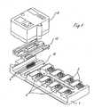
- the distributoris composed of several components. It contains a first component 1 with the actual actuator-sensor installation and its passive wiring. Various connections 2 in the form of sockets are provided in the first component 1, into which the connectors of the cables leading to the actuators and / or sensors can be inserted. In the first component 1, the terminals 2 are in electrically conductive connection with a printed circuit board 3 whose printed conductors lead to a group of contact pins 4. The circuit board 3 in the first, passive component 1 is otherwise equipped with only a few light-emitting diodes and resistors.
- Component 1is designed in protection class IP 67.
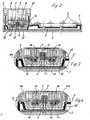
- a corresponding course of a potting compound 5is in FIG. 2 illustrated.
- the distributorincludes a second, separate component 6, which contains the electronics for the supply of the actuators and / or sensors and the forwarding of the actuator-sensor signals.
- This second electronic component 6is electrically and mechanically detachable and thus interchangeably connected to the first passive component 1.
- the electronic component 6is a circuit board 7, which is equipped depending on the corresponding application with appropriate electronic components 8 and further equipped with a pin group 4 of the passive component 1 correspondingly configured socket 9, so that during assembly of the two components on the Contact pins 4 and the socket 9 their electrical connection is made by plugging.
- fastening screws 10are provided, with which the electronic component 6 can be screwed onto the first passive component 1.
- the electronic component 6is a pure service part, which can be easily replaced in the event of damage to the electronics.
- the passive wiring in component 1stops.
- the first component 1is particularly suitable for mounting on a machine or on a machine or apparatus frame. When replacing the electronic component 6, this can be unscrewed directly “from above” from the first component. It is therefore no longer necessary to solve the first component 1 consuming of the machine, the first component 1 may rather remain in its mounting position on the machine.
- a typical field of application for such distributorsis the connection of the actuators and / or sensors to a bus system, in particular the connection with formwork cable.
- the embodiments shown in the drawingsrefer to such an embodiment.
- a respect to the form-fitting cable 11is provided with a cross-section neutral recording 12 for this application in the first passive component 1.
- the printed circuit board 7 of the electronic component 6is equipped with a number of contact pins 14, which are provided in a number and spatial position corresponding to the purpose and in the assembly of the component 1 and the component 6 functionally the corresponding conductors in the Form effetsraden 11th Contact insulation penetrating.
- the cable duct piece 13has a passage opening for the contact pins 4 and the socket 9.
- the cable channel piece 13can be used offset by 180 ° in the cross-section neutral receptacle 12 of the component 1, so that the form-line cable 1 can be supplied to the manifold in different directions.
- a cable duct piece for all provided form-line cablethe implementation leads by 180 ° to a polarity reversal with respect to the position of the Form effetsrade 11 in the cable channel piece 13.
- FIGS. 3 and 4show, in a corresponding partial detail, an electronic component 6a with respect to the electronic component 6 FIG. 3 inverse polarity.
Landscapes
- Engineering & Computer Science (AREA)
- Microelectronics & Electronic Packaging (AREA)
- Details Of Connecting Devices For Male And Female Coupling (AREA)
- Power Steering Mechanism (AREA)
- Vehicle Body Suspensions (AREA)
- Air Bags (AREA)
- Manufacturing Of Electrical Connectors (AREA)
- Connections By Means Of Piercing Elements, Nuts, Or Screws (AREA)
- Connector Housings Or Holding Contact Members (AREA)
Abstract
Description
Translated fromGermanDie Erfindung betrifft einen Verteiler zum Verbinden von Aktoren und/oder Sensoren nach dem Oberbegriff des Anspruchs 1.The invention relates to a distributor for connecting actuators and / or sensors according to the preamble of claim 1.
Verteiler sind in ihrem grundsätzlichen Aufbau bekannt (
Die
Ein typischer Einsatzbereich der Verteiler ist die Verbindung der Aktoren und/oder Sensoren mit einem Bussystem, insbesondere mit entsprechenden Formleitungskabeln.A typical area of application of the distributors is the connection of the actuators and / or sensors to a bus system, in particular to corresponding form-line cables.
Es ist bei einfachen Aufnahmevorrichtungen für derartige Formleitungskabel bekannt (
Der vorliegenden Erfindung liegt die Aufgabe zugrunde, einen Verteiler der gattungsgemäßen Art zu schaffen, der bei Gewährleistung einer hohen Schutzart besonderes servicefreundlich ist.The present invention has for its object to provide a distributor of the generic type, which is particularly easy to service while ensuring a high degree of protection.
Die Erfindung löst diese Aufgabe durch den Gegenstand des Anspruchs 1.The invention solves this problem by the subject matter of claim 1.
Die Möglichkeit der Zuführung der Formleitungskabel aus unterschiedlichen Richtungen nunmehr mit Polaritätswechsel ergibt insoweit neue Kabelverlegemöglichkeiten und damit neue Montagemöglichkeiten aufeinanderfolgender derartiger Verteiler innerhalb eines Systems, die in zahlreichen Anwendungsfällen besonders installationsfreundlich sind. Es wird dabei ausgenutzt, dass systembedingt sowieso mehrere unterschiedlich ausgelegte Elektronikbauteile vorgesehen sind und sich im Rahmen eines derartigen Bausatzes problemlos Elektronikbauteile unterschiedlicher Polarität ausgestalten lassen.The possibility of feeding the Formleitungskabel from different directions now with polarity change results in so far new Kabelverlegemöglichkeiten and thus new mounting options successive such distributor within a system, which are particularly easy to install in many applications. It is thereby exploited that, depending on the system, a plurality of differently designed electronic components are anyway provided and electronic components of different polarity can easily be configured within the scope of such a kit.
Dank dieser Ausgestaltung kann im Fall eines Schadens an der Elektronik das Elektronikbauteil als reines Serviceteil problemlos ausgewechselt werden, während das erste Bauteil mit der passiven Verkabelung der eigentlichen Sensor-Aktor-Installation erhalten bleibt und damit auch die passive Verkabelung stehen bleibt. Dank dieser Bauweise des Verteilers können auch die ihn bildenden Bauteile jeweils für sich genommen problemlos in einer hohen Schutzart, insbesondere in einer Schutzart größer als IP 65, beispielsweise IP 67, ausgeführt werden.Thanks to this configuration, in the case of damage to the electronics, the electronic component can be easily replaced as a pure service part, while the first component with the passive wiring of the actual sensor-actuator installation is maintained and thus the passive wiring stops. Thanks to this design of the distributor and the components forming it can also be taken for themselves in a high degree of protection, especially in a degree of protection greater than IP 65, for example IP 67, taken alone.
Dieser grundsätzliche Aufbau eines Verteilers führt in weitererbesonders zweckmäßiger Ausgestaltung auch problemlos zu einer bausatzartigen Ausgestaltung eines derartigen Verteilers dergestalt, dass für ein erstes Bauteil mit der passiven Verkabelung mehrere unterschiedlich ausgelegte Elektronikbauteile bausatzartig versehen sind.This basic structure of a distributor leads in a particularly useful embodiment also easily to a kit-like design of such a distributor such that a plurality of differently designed electronic components are kit-like provided for a first component with the passive wiring.
Weiter bevorzugte Ausgestaltungen ergeben sich aus den Unteransprüchen.Further preferred embodiments will be apparent from the dependent claims.
Ausführungsbeispiele des Erfindungsgegenstandes werden nachstehend unter Bezugnahme auf die Zeichnung näher beschrieben.Embodiments of the subject invention will be described below with reference to the drawings.
Es zeigen:
- Figur 1
- einen Verteiler gemäß der Erfindung in sprengbildlicher Darstellung,
- Figur 2
- einen montierten Verteiler gemäß der Erfindung im Längsschnitt,
- Figur 3
- eine Einzelheit des Verteilers nach
Figur 2 , - Figur 4
- eine Einzelheit entsprechend
Figur 2 bei einem weiteren Verteiler gemäß der Erfindung.
- FIG. 1
- a distributor according to the invention in an exploded view,
- FIG. 2
- a mounted distributor according to the invention in longitudinal section,
- FIG. 3
- a detail of the distributor after
FIG. 2 . - FIG. 4
- a detail accordingly
FIG. 2 in another distributor according to the invention.
Der Verteiler setzt sich aus mehreren Bauteilen zusammen. Er beinhaltet ein erstes Bauteil 1 mit der eigentlichen Aktor-Sensor-Installation und deren passiver Verkabelung. In dem ersten Bauteil 1 sind diverse Anschlüsse 2 in Form von Buchsen vorgesehen, in die die Stecker der zu den Aktoren und/oder Sensoren führenden Kabel eingesteckt werden können. In dem ersten Bauteil 1 stehen die Anschlüsse 2 in elektrisch leitender Verbindung mit einer Leiterplatte 3, deren Leiterbahnen zu einer Gruppe von Kontaktstiften 4 führen. Die Leiterplatte 3 im ersten, passiven Bauteil 1 ist im übrigen nur mit einigen Leuchtdioden und Widerständen bestückt.The distributor is composed of several components. It contains a first component 1 with the actual actuator-sensor installation and its passive wiring. Various connections 2 in the form of sockets are provided in the first component 1, into which the connectors of the cables leading to the actuators and / or sensors can be inserted. In the first component 1, the terminals 2 are in electrically conductive connection with a printed circuit board 3 whose printed conductors lead to a group of contact pins 4. The circuit board 3 in the first, passive component 1 is otherwise equipped with only a few light-emitting diodes and resistors.
Das Bauteil 1 ist in der Schutzart IP 67 ausgeführt. Ein dementsprechender Verlauf einer Vergußmasse 5 ist in
Der Verteiler beinhaltet in seinem grundsätzlichen Aufbau ein zweites, gesondertes Bauteil 6, das die Elektronik für die Versorgung der Aktoren und/oder Sensoren und die Weiterleitung der Aktoren-Sensoren-Signale beinhaltet. Dieses zweite Elektronikbauteil 6 ist elektrisch und mechanisch lösbar und damit auswechselbar mit dem ersten passiven Bauteil 1 verbunden. Im dem Elektronikbauteil 6 befindet sich eine Leiterplatte 7, die je nach dem entsprechenden Anwendungsfall mit entsprechenden Elektronikbauelementen 8 bestückt ist und ferner mit einer der Kontaktstiftgruppe 4 des passiven Bauteiles 1 entsprechend konfigurierten Buchse 9 bestückt ist, so daß bei der Montage der beiden Bauteile über die Kontaktstifte 4 und die Buchse 9 ihre elektrische Verbindung durch Steckung hergestellt wird. Zur mechanischen Verbindung sind Befestigungsschrauben 10 vorgesehen, mit denen das Elektronikbauteil 6 auf dem ersten passiven Bauteil 1 festgeschraubt werden kann.In its basic structure, the distributor includes a second,
Dank dieses grundsätzlichen Aufbaus ist das Elektronikbauteil 6 ein reines Serviceteil, das im Fall des Schadens an der Elektronik problemlos ausgewechselt werden kann. Die passive Verkabelung im Bauteil 1 bleibt dabei stehen. Das erste Bauteil 1 eignet sich insbesondere zur Montage an einer Maschine bzw. an einem Maschinen- oder Apparategestell. Beim Auswechseln des Elektronikbauteils 6 kann dieses direkt "von oben" vom ersten Bauteil abgeschraubt werden. Es ist somit nicht mehr notwendig, das erste Bauteil 1 aufwendig von der Maschine zu lösen, das erste Bauteil 1 kann vielmehr in seiner Montagestellung an der Maschine verbleiben.Thanks to this basic structure, the
Unter Beibehaltung des vorstehend geschilderten Aufbauprinzipes für einen derartigen Verteiler können mehrere Elektronikbauteile vorgesehen werden, die bezüglich der Weiterleitungsfunktion der Elektronik unterschiedlich gestaltet sind. Es kann sich dabei um Kabelanschlüsse aller Art aber auch Steckanschlüsse für weitere Module oder dergleichen handeln.While maintaining the construction principle described above for such a distributor, it is possible to provide a plurality of electronic components which are designed differently with regard to the forwarding function of the electronics. It may be cable connections of all kinds but also plug connections for other modules or the like.
Es versteht sich, daß auch die auswechselbaren Elektronikbauteile in der entsprechenden Schutzart, beispielsweise IP 67, auszuführen sind. Im übrigen wird auch eine entsprechend dichte Steckverbindungsart bei den Anschlüssen 2 für die Kabel zu den Aktoren und/oder Sensoren vorgesehen.It is understood that the interchangeable electronic components in the appropriate degree of protection, such as IP 67, are executed. Moreover, a correspondingly tight connector type is provided at the terminals 2 for the cables to the actuators and / or sensors.
Ein typisches Anwendungsgebiet für derartige Verteiler ist die Verbindung der Aktoren und/oder Sensoren mit einem Bussystem, insbesondere die Verbindung mit ForrnleitungskabeIn. Die in den Zeichnungen dargestellten Ausführungsformen beziehen sich auf eine solche Ausführung.A typical field of application for such distributors is the connection of the actuators and / or sensors to a bus system, in particular the connection with formwork cable. The embodiments shown in the drawings refer to such an embodiment.
Im dargestellten Ausführungsbeispiel ist für diesen Anwendungsfall in dem ersten passiven Bauteil 1 eine bezüglich der Formleitungskabel 11 querschnittsneutrale Aufnahme 12 vorgesehen. In diese kann ein im Ausführungsbeispiel bezüglich zweier Formleitungskabel 11 querschnittsadaptiertes Kabelkanalstück 13 eingesetzt werden, das dann die beiden Formleitungskabel 11 in einer vorgegebenen Raumlage aufnimmt. Bei einem derartigen Anwendungsfall ist die Leiterplatte 7 des Elektronikbauteiles 6 mit einer Anzahl von Kontaktstiften 14 bestückt, die in einer dem Einsatzzweck entsprechenden Anzahl und Raumlage vorgesehen sind und die bei der Montage des Bauteiles 1 und des Bauteiles 6 funktionsgerecht die entsprechenden Leiter in den Formleitungskabeln 11 isolationsdurchdringend kontaktieren.In the illustrated embodiment, a respect to the form-
Das Kabelkanalstück 13 hat eine Durchtrittsöffnung für die Kontaktstifte 4 und die Buchse 9.The
Das Kabelkanalstück 13 kann um 180° versetzt in der querschnittsneutralen Aufnahme 12 des Bauteiles 1 eingesetzt werden, so daß die Formleitungskabel 1 dem Verteiler in unterschiedlicher Richtung zugeführt werden können. Bei dieser Ausgestaltung eines Kabelkanalstückes für sämtliche vorgesehene Formleitungskabel führt die Umsetzung um 180° zu einer Polatitätsvertauschung bezüglich der Lage der Formleitungskabel 11 im Kabelkanalstück 13. Dies ergibt sich aus einem Vergleich der
Im Rahmen des Verteilerbausatzes können weitere je nach Einsatzzweck bezüglich ihrer Bestückung unterschiedlich ausgelegte Elektronikbauteile vorgesehen sein.As part of the distributor kit further depending on the intended use in terms of their assembly differently designed electronic components can be provided.
Claims (7)
- Distributor for connecting actuators and/or sensors to moulded connector cables, with connectors (2) for the actuators and/or sensors and an electronic unit (8) for the supply of the actuators and/or sensors and for relaying the actuator-sensor signals, such that a cable holder (12) is provided for the connector cable (11) in a first component (1), the distributor comprising a first component (1) with the said connectors (2) for connecting the actuators and/or sensors and a second, separate component (6) with the electronic unit (8), and the components (1 and 6) can be releasably connected mechanically and electrically to one another, and in the first component (1) a cross-section-neutral holder (12) for moulded connector cables (5) is provided,characterised in that a cross-section-adapted cable track component (13) for at least two connector cables (11), which can be moved through 180°, can be inserted into the holder (12) and two electronic components (6, 6a) of different polarity are provided.
- Distributor according to Claim 1,characterised in that in a modular manner, several differently designed electronic components (6, 6a) are provided.
- Distributor according to Claims 1 or 2,characterised in that all the components (1, 6, 6a) are designed in accordance with IP65 or IP67 safety standards and are protected by means of a sealing compound.
- Distributor according to any of the preceding claims,characterised in that in the first component (1) the connectors (2) are in electrically conducting contact with a printed circuit board which, for its part, is fitted with an array of contact pins (4) for which a correspondingly designed socket (9) is provided with the printed circuit (7) of the electronic component (6, 6a) for the purpose of electrical plug-in connection.
- Distributor according to any of the preceding claims,characterised in that a through-aperture is provided in the cable track component (13) for the contact pins (4) and the socket (9).
- Distributor according to any of the preceding claims,characterised in that the printed circuit (7) of the electronic component (6, 6a) is provided with contact pins (14) for making contact with the connector cable (11) by penetrating through the insulation thereof.
- Distributor according to any of the preceding claims,characterised in that the first component (1) is designed to be mounted directly on a machine and/or a machine and/or apparatus frame, so that the electronic component (6) can be exchanged without removing the first component (1) from its mounted position.
Applications Claiming Priority (2)
| Application Number | Priority Date | Filing Date | Title |
|---|---|---|---|
| DE29905025UDE29905025U1 (en) | 1999-03-19 | 1999-03-19 | Distributor for connecting actuators and / or sensors |
| EP00104989AEP1039589B1 (en) | 1999-03-19 | 2000-03-09 | Distributor for connecting actuators and/or sensors |
Related Parent Applications (2)
| Application Number | Title | Priority Date | Filing Date |
|---|---|---|---|
| EP00104989ADivisionEP1039589B1 (en) | 1999-03-19 | 2000-03-09 | Distributor for connecting actuators and/or sensors |
| EP00104989.9Division | 2000-03-09 |
Publications (3)
| Publication Number | Publication Date |
|---|---|
| EP1892804A2 EP1892804A2 (en) | 2008-02-27 |
| EP1892804A3 EP1892804A3 (en) | 2008-03-12 |
| EP1892804B1true EP1892804B1 (en) | 2010-04-14 |
Family
ID=8071071
Family Applications (2)
| Application Number | Title | Priority Date | Filing Date |
|---|---|---|---|
| EP07123155AExpired - LifetimeEP1892804B1 (en) | 1999-03-19 | 2000-03-09 | Distributor for connecting actuators and/or sensors |
| EP00104989AExpired - LifetimeEP1039589B1 (en) | 1999-03-19 | 2000-03-09 | Distributor for connecting actuators and/or sensors |
Family Applications After (1)
| Application Number | Title | Priority Date | Filing Date |
|---|---|---|---|
| EP00104989AExpired - LifetimeEP1039589B1 (en) | 1999-03-19 | 2000-03-09 | Distributor for connecting actuators and/or sensors |
Country Status (4)
| Country | Link |
|---|---|
| EP (2) | EP1892804B1 (en) |
| AT (2) | ATE464681T1 (en) |
| DE (3) | DE29905025U1 (en) |
| ES (1) | ES2306640T3 (en) |
Families Citing this family (13)
| Publication number | Priority date | Publication date | Assignee | Title |
|---|---|---|---|---|
| DE29915886U1 (en)* | 1999-09-09 | 2001-01-25 | Weidmüller Interface GmbH & Co, 32760 Detmold | Distributor for connecting actuators and / or sensors |
| DE29919900U1 (en)* | 1999-11-13 | 2001-03-29 | Weidmüller Interface GmbH & Co, 32760 Detmold | Distribution system |
| DE29919901U1 (en)* | 1999-11-13 | 2001-04-05 | Weidmüller Interface GmbH & Co, 32760 Detmold | Distributor for connecting actuators and / or sensors |
| DE20100091U1 (en)* | 2001-01-04 | 2002-05-16 | Weidmüller Interface GmbH & Co., 32760 Detmold | Distributor for the supply of actuators and / or sensors |
| DE20100165U1 (en)* | 2001-01-05 | 2002-05-08 | Weidmüller Interface GmbH & Co., 32760 Detmold | Distributor for the supply of actuators and / or sensors |
| DE50205981D1 (en)* | 2001-03-23 | 2006-05-04 | Sartorius Hamburg Gmbh | Connection system for connecting load cells |
| GB2398931A (en)* | 2003-02-07 | 2004-09-01 | Paul Atkins | Testing Adaptor |
| DE102004031434A1 (en)* | 2004-06-29 | 2006-01-26 | Michael Wolter | Electronic component for connecting to a ribbon cable with multiple conductors has a casing with a circuit board having an electronic switching circuit |
| DE202006015946U1 (en) | 2006-10-18 | 2008-02-28 | Weidmüller Interface GmbH & Co. KG | Connection system for the realization of branches on continuous conductors |
| DE102007019095A1 (en)* | 2007-04-23 | 2008-11-06 | Continental Automotive Gmbh | Standardized carrier element with integrated interface |
| US11296467B2 (en) | 2012-11-06 | 2022-04-05 | Server Technology, Inc. | High outlet density power distribution unit |
| JP6143874B2 (en) | 2012-11-06 | 2017-06-07 | サーバー テクノロジー インコーポレイテッド | High-density outlet power distribution unit |
| DE102013105518A1 (en) | 2013-05-29 | 2014-12-04 | Escha Bauelemente Gmbh | signal distributor |
Family Cites Families (11)
| Publication number | Priority date | Publication date | Assignee | Title |
|---|---|---|---|---|
| DE4320327C1 (en)* | 1993-04-13 | 1994-06-01 | Siemens Ag | Sensors or actuators for connection onto bus line - have block with blade contacts that are loaded to pierce cable insulation that is secured by screw clamping unit |
| JP3238405B2 (en)* | 1993-04-14 | 2001-12-17 | シーメンス アクチエンゲゼルシヤフト | Module for connecting actuators and / or sensors |
| DE4402001B4 (en)* | 1994-01-18 | 2007-02-22 | Wago Verwaltungsgesellschaft Mbh | I / O module for a data bus |
| DE4438804C1 (en) | 1994-10-31 | 1996-03-28 | Weidmueller Interface | Modular control system with bus conductor e.g. B. for building automation |
| DE4438806C1 (en) | 1994-10-31 | 1996-03-21 | Weidmueller Interface | Modular control system with bus conductor |
| DE19648298C1 (en)* | 1996-11-21 | 1997-12-18 | Siemens Ag | Hat-shaped rail with integrated cable e.g. for snap-fitting of contactors or time-relays |
| DE19814810C1 (en) | 1998-04-02 | 1999-06-10 | Kloeckner Moeller Gmbh | Adaptor for current bus bars |
| DE19748429A1 (en) | 1997-11-03 | 1999-05-06 | Siemens Ag | Switchgear unit capable of communication |
| DE19756167C2 (en) | 1997-12-17 | 2003-12-11 | Ifm Electronic Gmbh | Coupling module for connecting a user module |
| DE19807710C2 (en) | 1998-02-24 | 2002-07-18 | Siemens Ag | Modular automation device and assembly of a modular automation device |
| DE29818052U1 (en) | 1998-10-13 | 1999-02-04 | Pepperl & Fuchs GmbH, 68307 Mannheim | Receiving device for cables with non-uniform insulation cross-section |
- 1999
- 1999-03-19DEDE29905025Upatent/DE29905025U1/ennot_activeExpired - Lifetime
- 2000
- 2000-03-09DEDE50015906Tpatent/DE50015906D1/ennot_activeExpired - Lifetime
- 2000-03-09ATAT07123155Tpatent/ATE464681T1/enactive
- 2000-03-09EPEP07123155Apatent/EP1892804B1/ennot_activeExpired - Lifetime
- 2000-03-09ATAT00104989Tpatent/ATE395735T1/enactive
- 2000-03-09ESES00104989Tpatent/ES2306640T3/ennot_activeExpired - Lifetime
- 2000-03-09EPEP00104989Apatent/EP1039589B1/ennot_activeExpired - Lifetime
- 2000-03-09DEDE50015151Tpatent/DE50015151D1/ennot_activeExpired - Lifetime
Also Published As
| Publication number | Publication date |
|---|---|
| ATE395735T1 (en) | 2008-05-15 |
| DE50015906D1 (en) | 2010-05-27 |
| EP1892804A3 (en) | 2008-03-12 |
| EP1039589A1 (en) | 2000-09-27 |
| ATE464681T1 (en) | 2010-04-15 |
| EP1039589B1 (en) | 2008-05-14 |
| DE29905025U1 (en) | 1999-06-02 |
| EP1892804A2 (en) | 2008-02-27 |
| ES2306640T3 (en) | 2008-11-16 |
| DE50015151D1 (en) | 2008-06-26 |
Similar Documents
| Publication | Publication Date | Title |
|---|---|---|
| EP2023705B1 (en) | Adapter board, connector mounting and device for connecting an electronic controller with its connecting circuits | |
| EP0709933B1 (en) | Modular control installation with bus | |
| EP0709932B1 (en) | Modular control installation with bus, e.g. for automation of buildings | |
| DE2414566C2 (en) | Electric automatic system | |
| DE69816236T2 (en) | Interface device between parts of a system | |
| EP1892804B1 (en) | Distributor for connecting actuators and/or sensors | |
| DE19650989A1 (en) | Terminal block with lateral bridge contact e.g. for computer | |
| DE3740290C2 (en) | Device for controlling and / or regulating processes | |
| DE202011105337U1 (en) | Device for the electrical and mechanical connection of modules of a modular automation system | |
| DE4124487C2 (en) | adapter | |
| EP1584128B1 (en) | Modular wiring device | |
| EP2091113B1 (en) | Connection system for light strips or lights | |
| DE102012102842A1 (en) | Plug-in connection module mounted in recess of housing wall, has locking receptacle and/or locking unit which are configured so that secondary side of base plate rests against housing wall when clamping contact is inserted in housing | |
| DE29505272U1 (en) | Sensor-actuator distributor | |
| DE19837314A1 (en) | Arrangement for earth connection of several components has connecting element that latches onto bolt whose cylindrical surface forms electrical connection to connecting element surface | |
| DE19724254A1 (en) | Central electrical arrangement esp for motor vehicle | |
| DE29919901U1 (en) | Distributor for connecting actuators and / or sensors | |
| DE29909766U1 (en) | Terminal block, especially feed-through terminal block | |
| EP1531524A1 (en) | Electrical connector | |
| EP1100152A2 (en) | Distributor and distribution system | |
| DE2340773A1 (en) | Transfer plug connector for wiring system with spring strip - has terminal pins protruding above wiring plane for connection to respective cct. boards | |
| DE29919900U1 (en) | Distribution system | |
| EP1365478B1 (en) | Module aligned and adapter module | |
| EP2867958B1 (en) | Electrical apparatus having a top-hat rail mount and a conductor connection | |
| EP4052100B1 (en) | Interface arrangement for connecting at least one control device to a plurality of field instruments |
Legal Events
| Date | Code | Title | Description |
|---|---|---|---|
| PUAI | Public reference made under article 153(3) epc to a published international application that has entered the european phase | Free format text:ORIGINAL CODE: 0009012 | |
| PUAL | Search report despatched | Free format text:ORIGINAL CODE: 0009013 | |
| AC | Divisional application: reference to earlier application | Ref document number:1039589 Country of ref document:EP Kind code of ref document:P | |
| AK | Designated contracting states | Kind code of ref document:A2 Designated state(s):AT BE CH CY DE DK ES FI FR GB GR IE IT LI LU MC NL PT SE | |
| AK | Designated contracting states | Kind code of ref document:A3 Designated state(s):AT BE CH CY DE DK ES FI FR GB GR IE IT LI LU MC NL PT SE | |
| RAP1 | Party data changed (applicant data changed or rights of an application transferred) | Owner name:WEIDMUELLER INTERFACE GMBH & CO. KG Owner name:HIRSCHMANN AUTOMATION AND CONTROL GMBH | |
| 17P | Request for examination filed | Effective date:20080425 | |
| 17Q | First examination report despatched | Effective date:20080529 | |
| AKX | Designation fees paid | Designated state(s):AT BE CH CY DE DK ES FI FR GB GR IE IT LI LU MC NL PT SE | |
| GRAP | Despatch of communication of intention to grant a patent | Free format text:ORIGINAL CODE: EPIDOSNIGR1 | |
| GRAS | Grant fee paid | Free format text:ORIGINAL CODE: EPIDOSNIGR3 | |
| GRAA | (expected) grant | Free format text:ORIGINAL CODE: 0009210 | |
| AC | Divisional application: reference to earlier application | Ref document number:1039589 Country of ref document:EP Kind code of ref document:P | |
| AK | Designated contracting states | Kind code of ref document:B1 Designated state(s):AT BE CH CY DE DK ES FI FR GB GR IE IT LI LU MC NL PT SE | |
| REG | Reference to a national code | Ref country code:GB Ref legal event code:FG4D Free format text:NOT ENGLISH | |
| REG | Reference to a national code | Ref country code:CH Ref legal event code:EP | |
| REG | Reference to a national code | Ref country code:IE Ref legal event code:FG4D Free format text:LANGUAGE OF EP DOCUMENT: GERMAN | |
| REG | Reference to a national code | Ref country code:CH Ref legal event code:NV Representative=s name:ISLER & PEDRAZZINI AG | |
| REF | Corresponds to: | Ref document number:50015906 Country of ref document:DE Date of ref document:20100527 Kind code of ref document:P | |
| REG | Reference to a national code | Ref country code:NL Ref legal event code:T3 | |
| PG25 | Lapsed in a contracting state [announced via postgrant information from national office to epo] | Ref country code:SE Free format text:LAPSE BECAUSE OF FAILURE TO SUBMIT A TRANSLATION OF THE DESCRIPTION OR TO PAY THE FEE WITHIN THE PRESCRIBED TIME-LIMIT Effective date:20100414 Ref country code:ES Free format text:LAPSE BECAUSE OF FAILURE TO SUBMIT A TRANSLATION OF THE DESCRIPTION OR TO PAY THE FEE WITHIN THE PRESCRIBED TIME-LIMIT Effective date:20100725 | |
| REG | Reference to a national code | Ref country code:IE Ref legal event code:FD4D | |
| PG25 | Lapsed in a contracting state [announced via postgrant information from national office to epo] | Ref country code:FI Free format text:LAPSE BECAUSE OF FAILURE TO SUBMIT A TRANSLATION OF THE DESCRIPTION OR TO PAY THE FEE WITHIN THE PRESCRIBED TIME-LIMIT Effective date:20100414 | |
| PG25 | Lapsed in a contracting state [announced via postgrant information from national office to epo] | Ref country code:CY Free format text:LAPSE BECAUSE OF FAILURE TO SUBMIT A TRANSLATION OF THE DESCRIPTION OR TO PAY THE FEE WITHIN THE PRESCRIBED TIME-LIMIT Effective date:20100526 | |
| PG25 | Lapsed in a contracting state [announced via postgrant information from national office to epo] | Ref country code:DK Free format text:LAPSE BECAUSE OF FAILURE TO SUBMIT A TRANSLATION OF THE DESCRIPTION OR TO PAY THE FEE WITHIN THE PRESCRIBED TIME-LIMIT Effective date:20100414 Ref country code:PT Free format text:LAPSE BECAUSE OF FAILURE TO SUBMIT A TRANSLATION OF THE DESCRIPTION OR TO PAY THE FEE WITHIN THE PRESCRIBED TIME-LIMIT Effective date:20100816 Ref country code:IE Free format text:LAPSE BECAUSE OF FAILURE TO SUBMIT A TRANSLATION OF THE DESCRIPTION OR TO PAY THE FEE WITHIN THE PRESCRIBED TIME-LIMIT Effective date:20100414 | |
| PLBE | No opposition filed within time limit | Free format text:ORIGINAL CODE: 0009261 | |
| STAA | Information on the status of an ep patent application or granted ep patent | Free format text:STATUS: NO OPPOSITION FILED WITHIN TIME LIMIT | |
| 26N | No opposition filed | Effective date:20110117 | |
| PG25 | Lapsed in a contracting state [announced via postgrant information from national office to epo] | Ref country code:GR Free format text:LAPSE BECAUSE OF FAILURE TO SUBMIT A TRANSLATION OF THE DESCRIPTION OR TO PAY THE FEE WITHIN THE PRESCRIBED TIME-LIMIT Effective date:20100715 | |
| PG25 | Lapsed in a contracting state [announced via postgrant information from national office to epo] | Ref country code:MC Free format text:LAPSE BECAUSE OF NON-PAYMENT OF DUE FEES Effective date:20110331 | |
| REG | Reference to a national code | Ref country code:CH Ref legal event code:PUEA Owner name:WEIDMUELLER INTERFACE GMBH AND CO. KG, DE Free format text:FORMER OWNER: WEIDMUELLER INTERFACE GMBH AND CO. KG, DE | |
| REG | Reference to a national code | Ref country code:FR Ref legal event code:TP Owner name:WEIDMULLER INTERFACE GMBH & CO. KG, DE Effective date:20130111 | |
| REG | Reference to a national code | Ref country code:NL Ref legal event code:SD Effective date:20130311 | |
| REG | Reference to a national code | Ref country code:GB Ref legal event code:732E Free format text:REGISTERED BETWEEN 20130530 AND 20130605 | |
| REG | Reference to a national code | Ref country code:FR Ref legal event code:PLFP Year of fee payment:16 | |
| PGFP | Annual fee paid to national office [announced via postgrant information from national office to epo] | Ref country code:IT Payment date:20150327 Year of fee payment:16 Ref country code:NL Payment date:20150323 Year of fee payment:16 Ref country code:LU Payment date:20150323 Year of fee payment:16 Ref country code:CH Payment date:20150325 Year of fee payment:16 | |
| PGFP | Annual fee paid to national office [announced via postgrant information from national office to epo] | Ref country code:GB Payment date:20150324 Year of fee payment:16 Ref country code:FR Payment date:20150319 Year of fee payment:16 Ref country code:AT Payment date:20150320 Year of fee payment:16 | |
| PGFP | Annual fee paid to national office [announced via postgrant information from national office to epo] | Ref country code:DE Payment date:20150408 Year of fee payment:16 | |
| PGFP | Annual fee paid to national office [announced via postgrant information from national office to epo] | Ref country code:BE Payment date:20150318 Year of fee payment:16 | |
| PG25 | Lapsed in a contracting state [announced via postgrant information from national office to epo] | Ref country code:BE Free format text:LAPSE BECAUSE OF NON-PAYMENT OF DUE FEES Effective date:20160331 | |
| REG | Reference to a national code | Ref country code:DE Ref legal event code:R119 Ref document number:50015906 Country of ref document:DE | |
| PG25 | Lapsed in a contracting state [announced via postgrant information from national office to epo] | Ref country code:LU Free format text:LAPSE BECAUSE OF NON-PAYMENT OF DUE FEES Effective date:20160309 | |
| REG | Reference to a national code | Ref country code:CH Ref legal event code:PL | |
| REG | Reference to a national code | Ref country code:AT Ref legal event code:MM01 Ref document number:464681 Country of ref document:AT Kind code of ref document:T Effective date:20160309 | |
| REG | Reference to a national code | Ref country code:NL Ref legal event code:MM Effective date:20160401 | |
| GBPC | Gb: european patent ceased through non-payment of renewal fee | Effective date:20160309 | |
| REG | Reference to a national code | Ref country code:FR Ref legal event code:ST Effective date:20161130 | |
| PG25 | Lapsed in a contracting state [announced via postgrant information from national office to epo] | Ref country code:CH Free format text:LAPSE BECAUSE OF NON-PAYMENT OF DUE FEES Effective date:20160331 Ref country code:DE Free format text:LAPSE BECAUSE OF NON-PAYMENT OF DUE FEES Effective date:20161001 Ref country code:NL Free format text:LAPSE BECAUSE OF NON-PAYMENT OF DUE FEES Effective date:20160401 Ref country code:FR Free format text:LAPSE BECAUSE OF NON-PAYMENT OF DUE FEES Effective date:20160331 Ref country code:GB Free format text:LAPSE BECAUSE OF NON-PAYMENT OF DUE FEES Effective date:20160309 Ref country code:LI Free format text:LAPSE BECAUSE OF NON-PAYMENT OF DUE FEES Effective date:20160331 | |
| PG25 | Lapsed in a contracting state [announced via postgrant information from national office to epo] | Ref country code:AT Free format text:LAPSE BECAUSE OF NON-PAYMENT OF DUE FEES Effective date:20160309 Ref country code:IT Free format text:LAPSE BECAUSE OF NON-PAYMENT OF DUE FEES Effective date:20160309 |