EP1890618B1 - Fixator or splint - Google Patents
Fixator or splintDownload PDFInfo
- Publication number
- EP1890618B1 EP1890618B1EP06727197.3AEP06727197AEP1890618B1EP 1890618 B1EP1890618 B1EP 1890618B1EP 06727197 AEP06727197 AEP 06727197AEP 1890618 B1EP1890618 B1EP 1890618B1
- Authority
- EP
- European Patent Office
- Prior art keywords
- fixator
- joint
- limb
- proximal
- articulation member
- Prior art date
- Legal status (The legal status is an assumption and is not a legal conclusion. Google has not performed a legal analysis and makes no representation as to the accuracy of the status listed.)
- Active
Links
- 208000010392Bone FracturesDiseases0.000claimsdescription58
- 239000000463materialSubstances0.000claimsdescription7
- 239000012858resilient materialSubstances0.000claimsdescription6
- 239000013536elastomeric materialSubstances0.000claimsdescription2
- 238000005259measurementMethods0.000claimsdescription2
- 206010017076FractureDiseases0.000description54
- 210000003414extremityAnatomy0.000description26
- 210000000988bone and boneAnatomy0.000description15
- 239000012634fragmentSubstances0.000description8
- 230000035876healingEffects0.000description6
- 238000000034methodMethods0.000description6
- 238000001356surgical procedureMethods0.000description6
- 210000004872soft tissueAnatomy0.000description5
- 210000003813thumbAnatomy0.000description5
- 229920003023plasticPolymers0.000description4
- 239000004033plasticSubstances0.000description4
- 210000000707wristAnatomy0.000description4
- 229910000831SteelInorganic materials0.000description3
- 239000010959steelSubstances0.000description3
- OKTJSMMVPCPJKN-UHFFFAOYSA-NCarbonChemical compound[C]OKTJSMMVPCPJKN-UHFFFAOYSA-N0.000description2
- 210000003423ankleAnatomy0.000description2
- 229910052799carbonInorganic materials0.000description2
- 239000000835fiberSubstances0.000description2
- 208000015181infectious diseaseDiseases0.000description2
- 230000008961swellingEffects0.000description2
- 238000013519translationMethods0.000description2
- 210000003857wrist jointAnatomy0.000description2
- 208000027502Ankle fractureDiseases0.000description1
- 208000032170Congenital AbnormalitiesDiseases0.000description1
- 208000026137Soft tissue injuryDiseases0.000description1
- 208000027418Wounds and injuryDiseases0.000description1
- 230000001464adherent effectEffects0.000description1
- 210000003010carpal boneAnatomy0.000description1
- 206010010121compartment syndromeDiseases0.000description1
- 238000012937correctionMethods0.000description1
- 238000000315cryotherapyMethods0.000description1
- 230000001419dependent effectEffects0.000description1
- 238000002283elective surgeryMethods0.000description1
- 238000002297emergency surgeryMethods0.000description1
- 210000003127kneeAnatomy0.000description1
- 210000002414legAnatomy0.000description1
- 239000007788liquidSubstances0.000description1
- 238000012986modificationMethods0.000description1
- 230000004048modificationEffects0.000description1
- 230000037368penetrate the skinEffects0.000description1
- 238000010111plaster castingMethods0.000description1
- 229920001084poly(chloroprene)Polymers0.000description1
- 230000002980postoperative effectEffects0.000description1
- 230000000717retained effectEffects0.000description1
- XLYOFNOQVPJJNP-UHFFFAOYSA-NwaterSubstancesOXLYOFNOQVPJJNP-UHFFFAOYSA-N0.000description1
Images


Classifications
- A—HUMAN NECESSITIES
- A61—MEDICAL OR VETERINARY SCIENCE; HYGIENE
- A61B—DIAGNOSIS; SURGERY; IDENTIFICATION
- A61B17/00—Surgical instruments, devices or methods
- A61B17/56—Surgical instruments or methods for treatment of bones or joints; Devices specially adapted therefor
- A61B17/58—Surgical instruments or methods for treatment of bones or joints; Devices specially adapted therefor for osteosynthesis, e.g. bone plates, screws or setting implements
- A61B17/60—Surgical instruments or methods for treatment of bones or joints; Devices specially adapted therefor for osteosynthesis, e.g. bone plates, screws or setting implements for external osteosynthesis, e.g. distractors, contractors
- A61B17/64—Devices extending alongside the bones to be positioned
- A61B17/6425—Devices extending alongside the bones to be positioned specially adapted to be fitted across a bone joint
- A—HUMAN NECESSITIES
- A61—MEDICAL OR VETERINARY SCIENCE; HYGIENE
- A61F—FILTERS IMPLANTABLE INTO BLOOD VESSELS; PROSTHESES; DEVICES PROVIDING PATENCY TO, OR PREVENTING COLLAPSING OF, TUBULAR STRUCTURES OF THE BODY, e.g. STENTS; ORTHOPAEDIC, NURSING OR CONTRACEPTIVE DEVICES; FOMENTATION; TREATMENT OR PROTECTION OF EYES OR EARS; BANDAGES, DRESSINGS OR ABSORBENT PADS; FIRST-AID KITS
- A61F5/00—Orthopaedic methods or devices for non-surgical treatment of bones or joints; Nursing devices ; Anti-rape devices
- A61F5/01—Orthopaedic devices, e.g. long-term immobilising or pressure directing devices for treating broken or deformed bones such as splints, casts or braces
- A61F5/04—Devices for stretching or reducing fractured limbs; Devices for distractions; Splints
- A61F5/05—Devices for stretching or reducing fractured limbs; Devices for distractions; Splints for immobilising
- A61F5/058—Splints
- A61F5/05841—Splints for the limbs
- A—HUMAN NECESSITIES
- A61—MEDICAL OR VETERINARY SCIENCE; HYGIENE
- A61F—FILTERS IMPLANTABLE INTO BLOOD VESSELS; PROSTHESES; DEVICES PROVIDING PATENCY TO, OR PREVENTING COLLAPSING OF, TUBULAR STRUCTURES OF THE BODY, e.g. STENTS; ORTHOPAEDIC, NURSING OR CONTRACEPTIVE DEVICES; FOMENTATION; TREATMENT OR PROTECTION OF EYES OR EARS; BANDAGES, DRESSINGS OR ABSORBENT PADS; FIRST-AID KITS
- A61F5/00—Orthopaedic methods or devices for non-surgical treatment of bones or joints; Nursing devices ; Anti-rape devices
- A61F5/01—Orthopaedic devices, e.g. long-term immobilising or pressure directing devices for treating broken or deformed bones such as splints, casts or braces
- A61F5/0102—Orthopaedic devices, e.g. long-term immobilising or pressure directing devices for treating broken or deformed bones such as splints, casts or braces specially adapted for correcting deformities of the limbs or for supporting them; Ortheses, e.g. with articulations
- A61F5/013—Orthopaedic devices, e.g. long-term immobilising or pressure directing devices for treating broken or deformed bones such as splints, casts or braces specially adapted for correcting deformities of the limbs or for supporting them; Ortheses, e.g. with articulations for the arms, hands or fingers
- A—HUMAN NECESSITIES
- A61—MEDICAL OR VETERINARY SCIENCE; HYGIENE
- A61F—FILTERS IMPLANTABLE INTO BLOOD VESSELS; PROSTHESES; DEVICES PROVIDING PATENCY TO, OR PREVENTING COLLAPSING OF, TUBULAR STRUCTURES OF THE BODY, e.g. STENTS; ORTHOPAEDIC, NURSING OR CONTRACEPTIVE DEVICES; FOMENTATION; TREATMENT OR PROTECTION OF EYES OR EARS; BANDAGES, DRESSINGS OR ABSORBENT PADS; FIRST-AID KITS
- A61F5/00—Orthopaedic methods or devices for non-surgical treatment of bones or joints; Nursing devices ; Anti-rape devices
- A61F5/01—Orthopaedic devices, e.g. long-term immobilising or pressure directing devices for treating broken or deformed bones such as splints, casts or braces
- A61F5/04—Devices for stretching or reducing fractured limbs; Devices for distractions; Splints
- A61F5/05—Devices for stretching or reducing fractured limbs; Devices for distractions; Splints for immobilising
- A61F5/058—Splints
- A61F5/05841—Splints for the limbs
- A61F5/05858—Splints for the limbs for the arms
- A61F5/05866—Splints for the limbs for the arms for wrists, hands, fingers or thumbs
- A—HUMAN NECESSITIES
- A61—MEDICAL OR VETERINARY SCIENCE; HYGIENE
- A61B—DIAGNOSIS; SURGERY; IDENTIFICATION
- A61B17/00—Surgical instruments, devices or methods
- A61B17/56—Surgical instruments or methods for treatment of bones or joints; Devices specially adapted therefor
- A61B17/58—Surgical instruments or methods for treatment of bones or joints; Devices specially adapted therefor for osteosynthesis, e.g. bone plates, screws or setting implements
- A61B17/60—Surgical instruments or methods for treatment of bones or joints; Devices specially adapted therefor for osteosynthesis, e.g. bone plates, screws or setting implements for external osteosynthesis, e.g. distractors, contractors
- A61B17/64—Devices extending alongside the bones to be positioned
- A61B17/6416—Devices extending alongside the bones to be positioned with non-continuous, e.g. hinged, pin-clamp connecting element
- A—HUMAN NECESSITIES
- A61—MEDICAL OR VETERINARY SCIENCE; HYGIENE
- A61B—DIAGNOSIS; SURGERY; IDENTIFICATION
- A61B17/00—Surgical instruments, devices or methods
- A61B2017/00831—Material properties
- A61B2017/00902—Material properties transparent or translucent
- A61B2017/00915—Material properties transparent or translucent for radioactive radiation
Definitions
- the present inventionrelates to a non-invasive external fixator particularly suitable for fracture fixation.
- Particular embodiments of the inventionrelate to an external fixator which allows for movement in a joint adjacent a fracture site; while certain embodiments relate to a fixator useful in movement, distraction and/or reduction of a fracture.
- a conventional means for fixing fracture fragmentsis an external fixator, which typically takes the form of a steel or other material rod spanning across the fracture which is fixed to the bone fragments using pins.
- the rodis located outside the body, while the pins penetrate the skin and are fixed in the bone.
- fixatorspans a joint, such as the wrist or ankle.
- the steel or other material rodmay not be articulated, thereby preventing movement of the joint.
- WO 94/23662discloses an example of an external fixator, comprising an elongate outer-body member having a cylindrical bore, and an elongate inner-body member having a cylindrical body.
- Articulated fixatorsare known, but these have disadvantages as well. Alignment of the articulation with the joint can be difficult if not impossible, due to articulation of the fixator not being in the plane of the joint line axis.
- Known devicesdo not allow movement in the joint's plane of motion. For example, the position of the articulation of the fixator is dependent on the position of the pins drilled in the bone which can only be drilled in a limited number of positions.
- known articulated fixatorsalso have the disadvantage that if the fractured joints are moved in fracture situation, this will disturb the fracture position, In particular, known devices allow for multidirectional movement, including rotation, thereby allowing the fracture position to slip.
- US 5,707,370discloses an accessory device which is removably applicable to a double ball-jointed fixator, in the form of a cage that surrounds both ball-joints of the fixator.
- US 4,538,600discloses an adjustable splint assembly comprising a lower strut and an upper strut pivotably connected to the lower strut.
- US 4,677,971discloses a wrist splint for the treatment of soft tissue injuries, as a splint after surgery or in fracture treatment of small bones of the wrist (carpal bones).
- the devicedoes not have rigid members connected by an articulation piece according to the present invention.
- the device in US 4,677,971is not suitable for treating long bone fractures because the articulation piece is not at the fracture site or joint level and does not allow movement in the joint plane.
- an external non-invasive fixator for fixing a long bone fracture of a limbcomprising:
- 'proximal'is meant the portion of the fixator for mounting nearest the body of a patient
- 'distal'means the portion of the fixator for mounting furthest from the body of a patient
- the present inventionallows for bone fragments to be maintained in position during healing by virtue of the rigid members and proximal and distal portions.
- the articulation memberpermits movement between the two portions of the fixator, such that the patient is able to flex a joint or move a limb in the vicinity of the fracture to alleviate fatigue and reduce stiffness while still retaining the fracture fragments in alignment.
- the fixatoris non-invasive and hence there is no risk of infection or complications of invasive surgery. Being non-invasive, the fixator can be placed in such a fashion that the plane of movement of the joint is in line with the plane of movement of articulating segment of the device, so minimising the chances of disturbing the position of fracture fragments when the joint is mobilised, improving patient comfort and healing. With invasive pin fixators such positioning is difficult to achieve because placement of the pins is constrained by the presence of the thumb, vital structures or other members of the limb.
- the device of the inventionis suitable for fixing a fracture.
- the term fractureincludes a fracture of the long bones.
- the devicecan be used during all stages of fixing the fracture, including for fracture reduction (moving the broken pieces of bone to normal configuration), fracture manipulation (moving fracture fragments) and treating fractures in such a fashion that the joint in proximity can be mobilised while maintaining the fracture position immobilised.
- the articulating memberallows all-plane movement and distraction.
- the universal jointmay comprise a ball-and-socket type joint, or may comprise a combination of planar joints or hinges arranged in a suitable orientation to permit movement in all three planes. Any other suitable arrangement may also be used.
- the articulation membercomprises selectively lockable universal joints. That is, the universal joints may be selectively restricted in at least one plane of movement, preferably two planes, and more preferably all three planes, together or separately.
- the articulation membermay comprise universal joints lockable in three planes and a lockable planar hinge joint. This allows the articulation member to be restricted in movement to the plane of movement of the patient's joint; this permits trans-articular movement of the patient's limb.
- the jointsmay be lockable by means of a grub screw or similar arrangement. The joints at the level of the fracture and the joint line may be separately lockable.
- the articulation membercomprises at least two universal joints, each joint articulating with a respective portion of the fixator, and preferably with a respective rigid member.
- This arrangementallows for a greater degree of available movement of the fixator when fitted, as well as a greater degree of possible alignment of the fixator during fitting, to conform to the shape of the patient's limb.
- the proximal part of the articulation memberis at the level of the fracture.
- the distal part of the articulation memberis at the level of joint line which also allows movement in the joint's plane of motion.
- the two universal jointsare at a right angle to each other.
- the universal jointsare preferably independently selectively lockable; in this way one joint may be left unlocked or locked in only one or two planes to permit movement of the limb, while the other joint may be locked in position to maintain a desired alignment of the proximal and distal portions of the fixator.
- the arrangementpermits translation, distraction, and movement in all planes at the fracture site and/or at the level of joint line.
- a universal jointis provided at the level of the fracture and at the level of the joint line.
- the articulation membermay also comprise a hinge joint.
- the articulation membercomprises a combination of two universal joints and a hinge joint and a distraction mechanism.
- the two universal jointsare at a right angle to each other. All joints may be selectively lockable.
- the provision of two universal joints with distraction mechanismallows for the fragment of a bone between the fracture site and joint (the broken piece) to be distracted/displaced in all three planes.
- This arrangement of the articulation member with selectively lockable jointsallows for fracture pieces to be manipulated, reduced in position, immobilised at fracture site and yet allows mobilisation of the joint in single plane.
- the articulating member according to the inventionallows for the hinge movement to be possible in all planes including movement along the axis of joint motion by virtue of selective locking capacity of two universal joints and the hinge joint
- the articulating memberallows all-plane movement and distraction.
- the articulation membermay be extendable, such that the length of the member may be adjusted. This may conveniently be provided by a telescopic portion of the member.
- the articulation memberis preferably lockable such that the length is fixed when locked.
- the articulation membermay be extended in use in order to provide for distraction of the fracture to assist healing.
- the articulation membermay conveniently comprise a threaded extendable portion, such that the length may be adjusted in small increments relatively straightforwardly.
- the articulation memberfurther comprises one or more measurement scales. Scales may be provided on the extendable portion, to measure the length of extension; or on one or more of the universal joints where present to measure the angle formed by the joints.
- the articulation memberis not made of a coil arrangement which would offer resistance to restrict the movement of the joint.
- the rigid membersare preferably elongate, and comprise rigid rods. Conveniently the rods are formed of carbon fibre, although other materials may be used.
- the rigid membersextend substantially parallel with the long axis of the patient's limb.
- proximal and distal portionsare in the form of a cuff, which may be secured around the patient's limb.
- the cuffmay be formed from rigid plastic or the like.
- the cuffcomprises an outer portion, of rigid material, and an inner portion, of resilient material.
- the resilient materialmay comprise an elastomeric material, such as neoprene or the like.
- the resilient materialmay be waterproof; alternatively, or in addition, the resilient material may be breathable.
- the inner lining of the cuffis made of water proof and air tight bladder.
- the term bladderis used to define an inflatable chamber or vesicle that can be air filled or filled with liquid.
- the bladdermay comprise a valve.
- the bladdermay have interconnected chambers so that it can be inflated using a single valve.
- the multiple chambersallow the bladder to conform to the shape of the limb of the individual patient.
- This bladder systemis made such that it may be adherent to overlying semi rigid plastic material.
- the inner portion of the cuffpreferably has a relatively high coefficient of friction, such that the cuff is securely retained on the patient's limb.
- the outer portion of the cuffpreferably does not in use extend fully around the patient's limb; the inner portion preferably does so extend. This reduces the risk that the rigid outer portion of the cuff will constrict the limb thereby causing swelling and compartment syndrome, while the inner portion may be used to provide a secure mounting of the cuff on the limb.
- the proximal portion of the fixatormay comprise two or more joined cuffs; this allows the fixation points to be located along the limb, providing a more secure fixation.
- the cuffsmay be joined with a stiffened member; for example, a plastic strip or tongue.
- the cuffscomprise portions for attaching to the rigid member.
- the attachment portionsmay comprise sleeves or the like through which the rigid member may pass.
- the attachment portionsmay further comprise means for fixing the rigid member into position; for example, grub screws or the like. These may be loosened to permit adjustment of the location of the rigid member with respect to the cuffs.
- the cuffs according to the inventionare secured to the limb so that once they are secured, they do not rotate or move otherwise.
- one or more of the proximal and distal portions and the articulation portionare radiolucent; preferably, all of the said portions are radiolucent.
- the fixatormay further comprise an external sheath for concealing the fixator. This improves the aesthetics of the device.
- the fixatoris adapted for use on a patient's arm; conveniently the fixator may be located in use with the rigid member on the opposite side of the arm from the patient's thumb (the ulnar side), that cannot be done with conventional invasive external fixators.
- a fixator for an armcomprising proximal and distal cuffs for mounting on an arm either side of a fracture, each of the cuffs including a rigid rod extending substantially parallel with the long axis of the patient's arm; and an articulation member connected to each of the rigid rods at respective first and second universal joints.
- a method of fixing a fracture in a patient's limbcomprises securing proximal and distal portions of a fixator on a limb either side of a fracture; and adjusting an articulation member comprising a universal joint connecting the proximal and distal portions to a desired position.
- a method of treating a fracturecomprises securing a fixator to a limb having a fracture, the fixator comprising proximal and distal portions each including a rigid member; and an articulation member connecting the proximal and distal portions, the articulation member comprising a universal joint for allowing relative movement between the proximal and distal portions.
- the fixatoris particularly useful in first aid methods when access to a hospital is not available as it can be readily applied. Furthermore, the fixator allows access to skin at the fracture site where local treatment, such as cryotherapy, may be applied. This is particularly important in fractures where significant soft tissue swelling ensues, such as ankle fractures. The fixator also allows for soft tissue access and wound care in postoperative cases.
- the fixatormay also be used in veterinary surgery.
- the fixator described hereinis particularly suitable for fracture fixation. Furthermore, the fixator described herein may also be used for soft tissues corrections and treatment of deformities. The articulations may provide the means for repeated adjustments. This is normally done by serial plaster casting which is time consuming and uncomfortable for the patient. The use of the fixator provides the advantage that it can be adjusted and allows movement of the joint.
- fixator described hereinmay be used after surgical procedures, which may comprise procedures on the bone or soft tissues or combination of both. These procedures may be for emergency or elective surgery where a certain position of the limb is to be maintained with or without allowing movement across the adjacent joint.
- the fixatormay also be provided as a kit of parts for assembly.
- a non-invasive external fixator 10according to the present invention is shown mounted on an arm 12 of a patient.
- the arm 12has a fracture 14 near the wrist.
- the fixator 10includes proximal 16 and distal 18 cuffs which are mounted either side of the fracture.
- Each cuff 16, 18includes a rigid plastics outer shell 20, 22 which is open at the lower part thereof (seen best in Figure 4 ), and a flexible elastomeric inner sleeve 24, 26 which encircles the patient's arm.
- the proximal cuff 16is divided into two portions 16a, 16b which are connected by a connecting bar 28, and includes two inner sleeves 24a, 24b.
- the connecting bar 28may be provided with an autograph plate.
- the inner sleevesmay be deformed to allow them to be passed over the patient's arm; the elastomeric nature of the inner sleeve will allow it to conform closely to the shape of the patient's arm.
- the outer shellmay also similarly deform to allow the fixator to be secured to the patient.
- Each cuff 16, 18includes a number of rigid loops 30 through which pass proximal and distal carbon fibre rods 32, 34.
- the loops 30are provided with grub screws 36 which may be tightened in order to retain the rigid rods within the loops.
- the rods 32, 34are joined by a connecting articulation piece 38.
- the articulation piece 38has proximal and distal universal ball and socket joints 40, 42 which are connected to the respective proximal and distal rods.
- the proximal joint 40is located at the level of the fracture 14, while the distal joint 42 is located at the level of the wrist joint.
- the ball and socket joints 40, 42are at a right angle to each other and may be locked in position by means of grub screws 44, 46.
- the central portion of the articulation piececomprises a telescoping member 48, which may also be locked using a grub screw.
- the distal portion of the articulation piece 38further comprises a lockable planar hinge joint 50, which permits rotation of the distal rod 34 in a single plane when the universal joint 42 is locked.
- the articulation piecepermits a range of useful movements of the fixator; the proximal and distal universal joints allow for the rods to be independently aligned and located relative to both the fracture and the limb joint, while the hinge joint 50 permits restricted movement of the limb joint when necessary.
- the universal jointsmay be fixed in position when the fracture is first set, or may be adjusted during healing to provide for translation, rotation, flexion, extension or medio-lateral movement of the bones around the fracture site.
- the telescoping memberpermits longitudinal movement of the fixator to provide for distraction of the fracture.
- the articulation piecemay include one or more graduated scales indicating the angle of adjustment of the universal joints, or the length of the telescoping member.
- a further advantage of the fixatoris that the rigid rods 32, 34 are located on the opposite side of the arm from the patient's thumb; this arrangement can be maintained even when the fracture is on the radial bone adjacent the thumb.
- the rodsmay be located at any convenient point on the fixator, thereby avoiding interference of the user's digits with correct positioning of the articulation piece.
- the various componentsare radiolucent, so that they do not interfere with X-rays of the fracture.
- the fixatormay be made light yet strong, as well as waterproof.
- the fixatormay include a cover to conceal the rods and other components for aesthetic reasons.
- the described embodimenthas been shown in use on an arm adjacent a wrist joint, it will be apparent that it may be used in other locations on the limb, such as adjacent the elbow, or on legs adjacent the knee or ankle.
- the shape and arrangement of the cuffsmay be modified as appropriate.
- the articulating piecehas been shown as essentially separate from the rods, in certain embodiments the universal joints and telescoping member may be integrated into the rigid rods.
Landscapes
- Health & Medical Sciences (AREA)
- Orthopedic Medicine & Surgery (AREA)
- Life Sciences & Earth Sciences (AREA)
- Animal Behavior & Ethology (AREA)
- Public Health (AREA)
- Heart & Thoracic Surgery (AREA)
- Veterinary Medicine (AREA)
- Engineering & Computer Science (AREA)
- Biomedical Technology (AREA)
- General Health & Medical Sciences (AREA)
- Nursing (AREA)
- Vascular Medicine (AREA)
- Surgery (AREA)
- Nuclear Medicine, Radiotherapy & Molecular Imaging (AREA)
- Medical Informatics (AREA)
- Molecular Biology (AREA)
- Surgical Instruments (AREA)
- Orthopedics, Nursing, And Contraception (AREA)
Description
- The present invention relates to a non-invasive external fixator particularly suitable for fracture fixation. Particular embodiments of the invention relate to an external fixator which allows for movement in a joint adjacent a fracture site; while certain embodiments relate to a fixator useful in movement, distraction and/or reduction of a fracture.
- When a bone is fractured, it is often necessary to hold the fragments of the bone together to allow for correct healing. If this is not done, problems such as misalignment or poor healing can occur.
- A conventional means for fixing fracture fragments is an external fixator, which typically takes the form of a steel or other material rod spanning across the fracture which is fixed to the bone fragments using pins. The rod is located outside the body, while the pins penetrate the skin and are fixed in the bone. This invasive technique involves surgery, and as such there is a risk of infection of the soft tissue or bone, and further there is a risk of complications arising from the surgery.
- A further disadvantage of conventional external fixators is where the fixator spans a joint, such as the wrist or ankle. The steel or other material rod may not be articulated, thereby preventing movement of the joint.
WO 94/23662 - Articulated fixators are known, but these have disadvantages as well. Alignment of the articulation with the joint can be difficult if not impossible, due to articulation of the fixator not being in the plane of the joint line axis. Known devices do not allow movement in the joint's plane of motion. For example, the position of the articulation of the fixator is dependent on the position of the pins drilled in the bone which can only be drilled in a limited number of positions. Furthermore, known articulated fixators also have the disadvantage that if the fractured joints are moved in fracture situation, this will disturb the fracture position, In particular, known devices allow for multidirectional movement, including rotation, thereby allowing the fracture position to slip.
US 5,707,370 discloses an accessory device which is removably applicable to a double ball-jointed fixator, in the form of a cage that surrounds both ball-joints of the fixator.US 4,538,600 discloses an adjustable splint assembly comprising a lower strut and an upper strut pivotably connected to the lower strut.US 4,677,971 discloses a wrist splint for the treatment of soft tissue injuries, as a splint after surgery or in fracture treatment of small bones of the wrist (carpal bones). However, the device does not have rigid members connected by an articulation piece according to the present invention. Furthermore, as with other known devices, the device inUS 4,677,971 is not suitable for treating long bone fractures because the articulation piece is not at the fracture site or joint level and does not allow movement in the joint plane.- In certain locations, such as for a fracture of the radial bone, the patient's thumb may prevent suitable alignment of the steel rod and the articulation. This problem has been addressed to a certain extent with ring external fixators, such as Ilazarov. However, such fixators necessitate a number of invasive pin placements and lead to a very big and cumbersome fixator.
- It is an object of the present invention to obviate or alleviate these and other disadvantages of conventional fixators. It is a further object of the invention to provide a non-invasive external fixator, which permits movement of a joint near the fracture site and also allows for fracture reduction and aids fracture manipulation.
- According to a first aspect of the present invention, there is provided an external non-invasive fixator for fixing a long bone fracture of a limb comprising:
- proximal and distal portions for mounting on the limb either side of the fracture, each of the proximal and distal portions comprising a rigid rod extending substantially parallel with a long axis of the limb; and
- an articulation member connecting the rigid rods that allows relative movement between the proximal and distal portions, the articulation member comprising a first universal joint that is arranged at a level of a joint line associated with a movable joint of the limb, and a second universal joint arranged at a level of the fracture, wherein the first and second universal joints are selectively lockable and unlockable to restrict and permit three-dimensional movement at each of the joint line and the fracture,
wherein one or both of the proximal and distal portions are in the form of a cuff which may be secured around the patient's limb. - By 'proximal' is meant the portion of the fixator for mounting nearest the body of a patient, while 'distal' means the portion of the fixator for mounting furthest from the body of a patient.
- The present invention allows for bone fragments to be maintained in position during healing by virtue of the rigid members and proximal and distal portions. The articulation member permits movement between the two portions of the fixator, such that the patient is able to flex a joint or move a limb in the vicinity of the fracture to alleviate fatigue and reduce stiffness while still retaining the fracture fragments in alignment. Further, the fixator is non-invasive and hence there is no risk of infection or complications of invasive surgery. Being non-invasive, the fixator can be placed in such a fashion that the plane of movement of the joint is in line with the plane of movement of articulating segment of the device, so minimising the chances of disturbing the position of fracture fragments when the joint is mobilised, improving patient comfort and healing. With invasive pin fixators such positioning is difficult to achieve because placement of the pins is constrained by the presence of the thumb, vital structures or other members of the limb.
- The device of the invention is suitable for fixing a fracture. The term fracture includes a fracture of the long bones. The device can be used during all stages of fixing the fracture, including for fracture reduction (moving the broken pieces of bone to normal configuration), fracture manipulation (moving fracture fragments) and treating fractures in such a fashion that the joint in proximity can be mobilised while maintaining the fracture position immobilised.
- In a preferred embodiment, the articulating member allows all-plane movement and distraction.
- The universal joint may comprise a ball-and-socket type joint, or may comprise a combination of planar joints or hinges arranged in a suitable orientation to permit movement in all three planes. Any other suitable arrangement may also be used.
- The articulation member comprises selectively lockable universal joints. That is, the universal joints may be selectively restricted in at least one plane of movement, preferably two planes, and more preferably all three planes, together or separately. In an alternative embodiment, the articulation member may comprise universal joints lockable in three planes and a lockable planar hinge joint. This allows the articulation member to be restricted in movement to the plane of movement of the patient's joint; this permits trans-articular movement of the patient's limb. The joints may be lockable by means of a grub screw or similar arrangement. The joints at the level of the fracture and the joint line may be separately lockable.
- In preferred embodiments, the articulation member comprises at least two universal joints, each joint articulating with a respective portion of the fixator, and preferably with a respective rigid member. This arrangement allows for a greater degree of available movement of the fixator when fitted, as well as a greater degree of possible alignment of the fixator during fitting, to conform to the shape of the patient's limb. The proximal part of the articulation member is at the level of the fracture. The distal part of the articulation member is at the level of joint line which also allows movement in the joint's plane of motion. Preferably, the two universal joints are at a right angle to each other. The universal joints are preferably independently selectively lockable; in this way one joint may be left unlocked or locked in only one or two planes to permit movement of the limb, while the other joint may be locked in position to maintain a desired alignment of the proximal and distal portions of the fixator. The arrangement permits translation, distraction, and movement in all planes at the fracture site and/or at the level of joint line. A universal joint is provided at the level of the fracture and at the level of the joint line.
- The articulation member may also comprise a hinge joint. In one preferred embodiment, the articulation member comprises a combination of two universal joints and a hinge joint and a distraction mechanism. Preferably, the two universal joints are at a right angle to each other. All joints may be selectively lockable. The provision of two universal joints with distraction mechanism allows for the fragment of a bone between the fracture site and joint (the broken piece) to be distracted/displaced in all three planes. This arrangement of the articulation member with selectively lockable joints allows for fracture pieces to be manipulated, reduced in position, immobilised at fracture site and yet allows mobilisation of the joint in single plane. Thus, the articulating member according to the invention allows for the hinge movement to be possible in all planes including movement along the axis of joint motion by virtue of selective locking capacity of two universal joints and the hinge joint
- Therefore, in a preferred embodiment, the articulating member allows all-plane movement and distraction.
- The articulation member may be extendable, such that the length of the member may be adjusted. This may conveniently be provided by a telescopic portion of the member. The articulation member is preferably lockable such that the length is fixed when locked. The articulation member may be extended in use in order to provide for distraction of the fracture to assist healing. The articulation member may conveniently comprise a threaded extendable portion, such that the length may be adjusted in small increments relatively straightforwardly.
- In preferred embodiments, the articulation member further comprises one or more measurement scales. Scales may be provided on the extendable portion, to measure the length of extension; or on one or more of the universal joints where present to measure the angle formed by the joints.
- Preferably, the articulation member is not made of a coil arrangement which would offer resistance to restrict the movement of the joint.
- The rigid members are preferably elongate, and comprise rigid rods. Conveniently the rods are formed of carbon fibre, although other materials may be used. The rigid members extend substantially parallel with the long axis of the patient's limb.
- One or both of the proximal and distal portions are in the form of a cuff, which may be secured around the patient's limb. The cuff may be formed from rigid plastic or the like. Preferably, the cuff comprises an outer portion, of rigid material, and an inner portion, of resilient material. The resilient material may comprise an elastomeric material, such as neoprene or the like. Preferably, the resilient material may be waterproof; alternatively, or in addition, the resilient material may be breathable.
- In another embodiment of the invention, the inner lining of the cuff is made of water proof and air tight bladder. The term bladder is used to define an inflatable chamber or vesicle that can be air filled or filled with liquid. The bladder may comprise a valve. The bladder may have interconnected chambers so that it can be inflated using a single valve. The multiple chambers allow the bladder to conform to the shape of the limb of the individual patient. This bladder system is made such that it may be adherent to overlying semi rigid plastic material.
- The inner portion of the cuff preferably has a relatively high coefficient of friction, such that the cuff is securely retained on the patient's limb. The outer portion of the cuff preferably does not in use extend fully around the patient's limb; the inner portion preferably does so extend. This reduces the risk that the rigid outer portion of the cuff will constrict the limb thereby causing swelling and compartment syndrome, while the inner portion may be used to provide a secure mounting of the cuff on the limb.
- The proximal portion of the fixator may comprise two or more joined cuffs; this allows the fixation points to be located along the limb, providing a more secure fixation. The cuffs may be joined with a stiffened member; for example, a plastic strip or tongue.
- Preferably, the cuffs comprise portions for attaching to the rigid member. The attachment portions may comprise sleeves or the like through which the rigid member may pass. The attachment portions may further comprise means for fixing the rigid member into position; for example, grub screws or the like. These may be loosened to permit adjustment of the location of the rigid member with respect to the cuffs.
- Preferably, the cuffs according to the invention are secured to the limb so that once they are secured, they do not rotate or move otherwise.
- Preferably, one or more of the proximal and distal portions and the articulation portion, are radiolucent; preferably, all of the said portions are radiolucent. The fixator may further comprise an external sheath for concealing the fixator. This improves the aesthetics of the device.
- Preferably the fixator is adapted for use on a patient's arm; conveniently the fixator may be located in use with the rigid member on the opposite side of the arm from the patient's thumb (the ulnar side), that cannot be done with conventional invasive external fixators.
- According to an aspect not related to the invention there is provided a fixator for an arm, the fixator comprising proximal and distal cuffs for mounting on an arm either side of a fracture, each of the cuffs including a rigid rod extending substantially parallel with the long axis of the patient's arm; and an articulation member connected to each of the rigid rods at respective first and second universal joints.
- A method of fixing a fracture in a patient's limb comprises securing proximal and distal portions of a fixator on a limb either side of a fracture; and adjusting an articulation member comprising a universal joint connecting the proximal and distal portions to a desired position.
- A method of treating a fracture comprises securing a fixator to a limb having a fracture, the fixator comprising proximal and distal portions each including a rigid member; and an articulation member connecting the proximal and distal portions, the articulation member comprising a universal joint for allowing relative movement between the proximal and distal portions.
- The fixator is particularly useful in first aid methods when access to a hospital is not available as it can be readily applied. Furthermore, the fixator allows access to skin at the fracture site where local treatment, such as cryotherapy, may be applied. This is particularly important in fractures where significant soft tissue swelling ensues, such as ankle fractures. The fixator also allows for soft tissue access and wound care in postoperative cases.
- The fixator may also be used in veterinary surgery.
- As described above, the fixator described herein is particularly suitable for fracture fixation. Furthermore, the fixator described herein may also be used for soft tissues corrections and treatment of deformities. The articulations may provide the means for repeated adjustments. This is normally done by serial plaster casting which is time consuming and uncomfortable for the patient. The use of the fixator provides the advantage that it can be adjusted and allows movement of the joint.
- Furthermore, the fixator described herein may be used after surgical procedures, which may comprise procedures on the bone or soft tissues or combination of both. These procedures may be for emergency or elective surgery where a certain position of the limb is to be maintained with or without allowing movement across the adjacent joint.
- The fixator may also be provided as a kit of parts for assembly.
- These and other aspects of the present invention will now be described by way of example only and without limitation with reference to the accompanying drawings in which
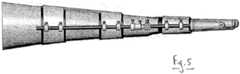
Figures 1 and2 show perspective views of a fixator in accordance with an embodiment of the invention mounted on a patient's arm; andFigures 3 ,4 , and5 show top, bottom, and side views respectively of the fixator ofFigures 1 and2 .- Referring to the Figures, a non-invasive
external fixator 10 according to the present invention is shown mounted on anarm 12 of a patient. Thearm 12 has afracture 14 near the wrist. - The
fixator 10 includes proximal 16 and distal 18 cuffs which are mounted either side of the fracture. Eachcuff 16, 18 includes a rigid plasticsouter shell Figure 4 ), and a flexible elastomericinner sleeve portions 16a, 16b which are connected by a connecting bar 28, and includes twoinner sleeves 24a, 24b. The connecting bar 28 may be provided with an autograph plate. To fit the fixator onto the patient, the inner sleeves may be deformed to allow them to be passed over the patient's arm; the elastomeric nature of the inner sleeve will allow it to conform closely to the shape of the patient's arm. The outer shell may also similarly deform to allow the fixator to be secured to the patient. - Each
cuff 16, 18 includes a number ofrigid loops 30 through which pass proximal and distalcarbon fibre rods loops 30 are provided withgrub screws 36 which may be tightened in order to retain the rigid rods within the loops. - The
rods articulation piece 38. Thearticulation piece 38 has proximal and distal universal ball andsocket joints fracture 14, while the distal joint 42 is located at the level of the wrist joint. The ball andsocket joints grub screws member 48, which may also be locked using a grub screw. The distal portion of thearticulation piece 38 further comprises a lockable planar hinge joint 50, which permits rotation of thedistal rod 34 in a single plane when theuniversal joint 42 is locked. - The articulation piece permits a range of useful movements of the fixator; the proximal and distal universal joints allow for the rods to be independently aligned and located relative to both the fracture and the limb joint, while the hinge joint 50 permits restricted movement of the limb joint when necessary. The universal joints may be fixed in position when the fracture is first set, or may be adjusted during healing to provide for translation, rotation, flexion, extension or medio-lateral movement of the bones around the fracture site. Finally, the telescoping member permits longitudinal movement of the fixator to provide for distraction of the fracture. The articulation piece may include one or more graduated scales indicating the angle of adjustment of the universal joints, or the length of the telescoping member.
- A further advantage of the fixator is that the
rigid rods - The various components are radiolucent, so that they do not interfere with X-rays of the fracture. Also, by using suitable materials the fixator may be made light yet strong, as well as waterproof. In certain embodiments the fixator may include a cover to conceal the rods and other components for aesthetic reasons.
- Although the described embodiment has been shown in use on an arm adjacent a wrist joint, it will be apparent that it may be used in other locations on the limb, such as adjacent the elbow, or on legs adjacent the knee or ankle. The shape and arrangement of the cuffs may be modified as appropriate. Further, although the articulating piece has been shown as essentially separate from the rods, in certain embodiments the universal joints and telescoping member may be integrated into the rigid rods.
- Other modifications and variations will be apparent to the skilled person.
Claims (17)
- An external non-invasive fixator (10) for fixing a long bone fracture (14) of a limb (12) comprising:proximal and distal portions (16, 18) for mounting on the limb (12) either side of the long bone fracture (14), each of the proximal and distal portions (16, 18) comprising a rigid rod (32, 34) extending substantially parallel with a long axis of the limb (12); andan articulation member (38) connecting the rigid rods (32, 34) that allows relative movement between the proximal and distal portions (16, 18), the articulation member (38) comprising a first universal joint (42) that is arranged at a level of a joint line associated with a movable joint of the limb (12), and a second universal joint (40) arranged at a level of the long bone fracture (14), wherein the first and second universal joints (40, 42) are selectively lockable and unlockable to restrict and permit three-dimensional movement at each of the joint line and the long bone fracture (14),wherein one or both of the proximal and distal portions (16, 18) are in the form of a cuff which may be secured around the patient's limb (12).
- The fixator of claim 1, wherein the universal joint comprises a ball-and-socket type joint.
- The fixator of claim 1 or 2, wherein the first and second universal joints (40, 42) are lockable in three planes, the fixator further comprising a lockable planar hinge joint (50) coupled to the first universal joint (42) that is configured to provide movement of the distal portion (18) and the movable joint in a single plane.
- The fixator of any preceding claim, wherein the articulation member (38) further comprises a hinge joint (50).
- The fixator of any preceding claim, wherein the universal joints (40, 42) and/or the hinge joint (50) are independently selectively lockable.
- The fixator of any preceding claim wherein the length of the articulation member (38) is adjustable.
- The fixator of any preceding claim, wherein the articulation member (38) comprises a telescopic portion (48).
- The fixator of claim 6 or 7 wherein the articulation member (38) is lockable such that the length is fixed when locked.
- The fixator of any preceding claim wherein the articulation member (38) comprises one or more measurement scales.
- The fixator of any preceding claim wherein the cuff comprises an outer portion (20, 22) and an inner portion (24, 26) wherein the inner portion (24, 26) is made of one or more inflatable chambers.
- The fixator of any preceding claim wherein the cuff comprises an outer portion (20, 22), of rigid material, and an inner portion (24, 26), of resilient material.
- The fixator of claim 11 wherein the resilient material comprises an elastomeric material.
- The fixator of claim 11 or 12 wherein the outer portion (20, 22) of the cuff does not in use extend fully around the patient's limb (12).
- The fixator of any preceding claim wherein the proximal portion (16) of the fixator comprises two or more joined cuffs.
- The fixator of any preceding claim wherein one or more of the proximal and distal portions (16, 18), and the articulation member (38), are radiolucent.
- The fixator of any preceding claim further comprising an external sheath for concealing the fixator.
- The fixator of any preceding claim adapted for use on a patient's arm.
Applications Claiming Priority (2)
| Application Number | Priority Date | Filing Date | Title |
|---|---|---|---|
| GB0509613AGB2425960A (en) | 2005-05-12 | 2005-05-12 | Adjustable splint |
| PCT/GB2006/050102WO2006120482A1 (en) | 2005-05-12 | 2006-05-12 | Fixator or splint |
Publications (2)
| Publication Number | Publication Date |
|---|---|
| EP1890618A1 EP1890618A1 (en) | 2008-02-27 |
| EP1890618B1true EP1890618B1 (en) | 2016-12-28 |
Family
ID=34685447
Family Applications (1)
| Application Number | Title | Priority Date | Filing Date |
|---|---|---|---|
| EP06727197.3AActiveEP1890618B1 (en) | 2005-05-12 | 2006-05-12 | Fixator or splint |
Country Status (9)
| Country | Link |
|---|---|
| US (1) | US7841998B2 (en) |
| EP (1) | EP1890618B1 (en) |
| JP (1) | JP4938002B2 (en) |
| CN (1) | CN101198283B (en) |
| AU (1) | AU2006245521B2 (en) |
| CA (1) | CA2608141C (en) |
| ES (1) | ES2619939T3 (en) |
| GB (1) | GB2425960A (en) |
| WO (1) | WO2006120482A1 (en) |
Families Citing this family (37)
| Publication number | Priority date | Publication date | Assignee | Title |
|---|---|---|---|---|
| DE102004029457A1 (en)* | 2004-06-18 | 2006-01-12 | Oped Ag | Wrist |
| DE102008022952A1 (en)* | 2008-05-09 | 2009-11-12 | Ludwig-Maximilians-Universität München | Non-invasive extension-, reposition and/or retention device for e.g. retention of e.g. ankle joint, has alignment device provided with two rotary degrees of freedom and/or transverse degrees of freedom |
| US20110313331A1 (en)* | 2009-02-10 | 2011-12-22 | Bruno Marc Florent Victore Dehez | Rehabilitation Robot |
| GB2467940A (en)* | 2009-02-20 | 2010-08-25 | Cambfix | Fixator |
| US20100280516A1 (en)* | 2009-04-30 | 2010-11-04 | Jeffrey Taylor | Accessory Device for an Orthopedic Fixator |
| US8562550B2 (en)* | 2009-05-27 | 2013-10-22 | Linares Medical Devices, Llc | Interior and exterior cast assemblies for repairing a bone fracture and including interior inflatable or mechanically expandable inserts as well as exterior wrap around and adhesively secured braces |
| CN102949259A (en)* | 2012-05-03 | 2013-03-06 | 陈春名 | Non-implantable external fixator |
| FR2991224B1 (en)* | 2012-06-04 | 2014-06-27 | Commissariat Energie Atomique | ARM OF EXOSQUELET WITH ACTUATOR |
| CN103989546B (en)* | 2013-02-18 | 2016-01-20 | 严松鹤 | Radius far-end fracture noinvasive adjustable type plywood support support |
| WO2014200366A2 (en)* | 2013-06-12 | 2014-12-18 | Pranesh Kumar | A splint |
| US9266231B1 (en)* | 2013-07-11 | 2016-02-23 | The Boeing Company | Hand-tool brace |
| CN104510553A (en)* | 2013-09-28 | 2015-04-15 | 沈阳新松机器人自动化股份有限公司 | Hand clamping mechanism and traction device |
| CN104510552B (en)* | 2013-09-28 | 2017-01-18 | 沈阳新松机器人自动化股份有限公司 | Fracture traction device |
| US9962188B2 (en) | 2013-10-29 | 2018-05-08 | Cardinal Health 247. Inc. | External fixation system and methods of use |
| US8998833B1 (en) | 2014-02-12 | 2015-04-07 | Abdulreidha Abdulrasoul AlSaffar | Orthopedic device and method for correcting skeletal abnormalities in a new-born baby |
| US9539134B2 (en) | 2014-02-12 | 2017-01-10 | Abdulreidha Abdulrasoul AlSaffar | Orthotic method and device for newborn babies |
| CN106308912A (en)* | 2014-10-24 | 2017-01-11 | 烟台小米机械技术有限公司 | Hand bone fixer for preventing osteonecrosis |
| CN104688307A (en)* | 2015-03-13 | 2015-06-10 | 王国栋 | Compulsive shaping device of bone joint |
| US9579230B1 (en) | 2015-10-08 | 2017-02-28 | Abdulreidha Abdulrasoul AlSaffar | Method and orthotic device for infant's neck |
| CN106264831B (en)* | 2016-08-24 | 2018-09-18 | 中国人民解放军第四军医大学 | A kind of air bag brace |
| CN107496070B (en)* | 2017-09-20 | 2019-11-12 | 王腾 | A kind of bone external fixer |
| DE102017127890A1 (en)* | 2017-11-24 | 2019-05-29 | Ottobock Se & Co. Kgaa | Hand orthosis and method for adjusting a hand orthosis |
| DE102017127892A1 (en)* | 2017-11-24 | 2019-05-29 | Ottobock Se & Co. Kgaa | Hand orthosis and system with a hand orthosis |
| CN107744446A (en)* | 2017-12-04 | 2018-03-02 | 陈彩飞 | A kind of hip joint protection support frame for being used to treat caput femoris necrosis |
| CN107997816B (en)* | 2017-12-06 | 2020-11-13 | 泰州新滨江环保科技有限公司 | Lower limb fracture fixing support based on medical care field |
| CN110227001A (en)* | 2018-03-05 | 2019-09-13 | 漯河市第一人民医院 | A kind of care of fractured fingers fixed frame |
| CN110269734B (en)* | 2018-03-14 | 2025-03-04 | 上海交通大学医学院附属瑞金医院 | A non-invasive traction splint |
| US12042414B2 (en) | 2018-03-27 | 2024-07-23 | Sean C. Norton | Splint device |
| CN108498230A (en)* | 2018-04-20 | 2018-09-07 | 王从相 | A kind of healing hand function adjuvant therapy device |
| DE102018115457B4 (en)* | 2018-06-27 | 2025-08-07 | Rahm Zentrum für Gesundheit GmbH | wrist orthosis |
| KR102748174B1 (en) | 2018-12-12 | 2024-12-31 | 삼성전자주식회사 | Link assembly and motion assist apparatus comprising the same |
| CN110090100A (en)* | 2019-05-31 | 2019-08-06 | 攀枝花学院 | The 3D printing production method of arm fracture fixing apparatus and arm fracture fixing apparatus |
| DE102019130404A1 (en)* | 2019-11-11 | 2021-05-12 | URS Entwicklung, Herstellung und Vertrieb medizinischer Produkte UG (haftungsbeschränkt) i.G. | Orthosis for the controlled movement and / or fixation of a forearm and / or a hand |
| CN110772345B (en)* | 2019-11-29 | 2021-01-15 | 段培君 | Orthopedic operation auxiliary device |
| KR102392184B1 (en)* | 2020-07-13 | 2022-04-27 | 부산대학교병원 | Combined traction functional cast |
| USD966532S1 (en)* | 2020-09-08 | 2022-10-11 | Neofect Co., Ltd. | Smart glove for rehabilitation |
| CN118436466B (en)* | 2024-05-16 | 2024-11-08 | 华中科技大学同济医学院附属同济医院 | A first aid fixation device for limb fracture trauma |
Family Cites Families (31)
| Publication number | Priority date | Publication date | Assignee | Title |
|---|---|---|---|---|
| DE82161C (en)* | ||||
| US1789060A (en)* | 1928-09-29 | 1931-01-13 | King Scheerer Corp | Bone-fracture clamp |
| DE2615209A1 (en)* | 1975-04-15 | 1976-10-28 | Teufel Wilh Jul Fa | UNIVERSAL ORTHESIS |
| US4834057A (en)* | 1980-03-31 | 1989-05-30 | Physical Diagnostics, Inc. | Dynamic joint motion analysis technique |
| DE3113981C1 (en)* | 1981-04-07 | 1982-11-11 | Otto Bock, Orthopädische Industrie KG, 3428 Duderstadt | Orthosis for the treatment of hip dysplasia and hip dislocation |
| US4583600A (en)* | 1981-04-30 | 1986-04-22 | Black & Decker Inc. | Impact tool |
| US4538600A (en) | 1983-10-27 | 1985-09-03 | Dynasplint Systems, Inc. | Adjustable splint |
| US4677971A (en)* | 1985-12-26 | 1987-07-07 | Rolyan Manufacturing Co. Inc | Adjustable wrist splint |
| FR2609887B3 (en)* | 1987-01-22 | 1989-05-19 | Marck Thierry | Hip splint |
| CH680769A5 (en)* | 1989-08-23 | 1992-11-13 | Jaquet Orthopedie | |
| US5002044A (en)* | 1989-10-10 | 1991-03-26 | Carter Peter R | Derotation wrist brace |
| US4977890A (en)* | 1989-11-17 | 1990-12-18 | Interstate Medical Marketing, Inc. | Hand splint |
| US5316547A (en)* | 1992-07-01 | 1994-05-31 | Smith & Nephew Donjoy, Inc. | Orthopedic brace having pneumatic pads |
| US5545162A (en)* | 1995-02-15 | 1996-08-13 | Huebner; Randall J. | External fixator for repairing fractures of distal radius and wrist |
| US5385536A (en)* | 1993-03-01 | 1995-01-31 | Wayne Z. Burkhead | Orthopedic brace for arm and shoulder |
| CA2121085A1 (en)* | 1993-04-13 | 1994-10-14 | Michael Saleh | Disposable external fixator |
| US5437619A (en)* | 1993-06-30 | 1995-08-01 | Empi, Inc. | Range-of-motion splint with eccentric spring |
| US5421810A (en)* | 1994-04-14 | 1995-06-06 | Orthomerica Products, Inc. | Orthopedic hinge assembly for an orthopedic brace |
| US5472410A (en)* | 1994-04-22 | 1995-12-05 | Deroyal/Lmb, Inc. | Adjustable flexion and extension joint orthoses |
| US5514081A (en)* | 1994-10-07 | 1996-05-07 | D'mannco, Inc. | Elbow orthosis having an inflatable bladder support and method of use |
| IT1278856B1 (en)* | 1995-09-19 | 1997-11-28 | Orthofix Srl | ACCESSORY FOR EXTERNAL FIXER |
| US5846245A (en)* | 1995-10-20 | 1998-12-08 | New York University | Bone-adjusting device |
| US5916184A (en)* | 1998-01-28 | 1999-06-29 | Mckeel; William H. | Orthopedic airflow and water proof cast padding material and method of making a cast |
| US6723061B2 (en)* | 1998-09-08 | 2004-04-20 | George Roger Williams | Dynamic splint for carpal tunnel syndrome treatment |
| US6179799B1 (en)* | 1999-02-01 | 2001-01-30 | Robert E. Doran | Orthosis for supination and pronation of the wrist |
| US6245071B1 (en)* | 1999-03-10 | 2001-06-12 | Synthes (U.S.A.) | External fixation device for bone |
| US7416537B1 (en)* | 1999-06-23 | 2008-08-26 | Izex Technologies, Inc. | Rehabilitative orthoses |
| US6589195B1 (en)* | 2000-05-26 | 2003-07-08 | Orthomerica Products, Inc. | Modular adjustable prophylactic hip orthosis and adduction/abduction joint |
| US6676619B2 (en)* | 2001-02-23 | 2004-01-13 | Wayne R. Arden | Method and apparatus for supporting a body part |
| US7476207B2 (en)* | 2001-08-27 | 2009-01-13 | Porrata Group Llc | Configurable apparatus and method for treating carpal tunnel syndrome |
| FR2842412B1 (en)* | 2002-07-19 | 2005-05-06 | Gerald Lefort | DYNAMIC ORTHESIS |
- 2005
- 2005-05-12GBGB0509613Apatent/GB2425960A/ennot_activeWithdrawn
- 2006
- 2006-05-12EPEP06727197.3Apatent/EP1890618B1/enactiveActive
- 2006-05-12CNCN2006800214733Apatent/CN101198283B/enactiveActive
- 2006-05-12AUAU2006245521Apatent/AU2006245521B2/enactiveActive
- 2006-05-12ESES06727197.3Tpatent/ES2619939T3/enactiveActive
- 2006-05-12USUS11/914,191patent/US7841998B2/enactiveActive
- 2006-05-12JPJP2008510649Apatent/JP4938002B2/enactiveActive
- 2006-05-12CACA2608141Apatent/CA2608141C/enactiveActive
- 2006-05-12WOPCT/GB2006/050102patent/WO2006120482A1/enactiveApplication Filing
Also Published As
| Publication number | Publication date |
|---|---|
| AU2006245521A1 (en) | 2006-11-16 |
| US7841998B2 (en) | 2010-11-30 |
| CA2608141A1 (en) | 2006-11-16 |
| CN101198283A (en) | 2008-06-11 |
| AU2006245521B2 (en) | 2011-12-22 |
| JP4938002B2 (en) | 2012-05-23 |
| CN101198283B (en) | 2010-05-19 |
| GB0509613D0 (en) | 2005-06-15 |
| CA2608141C (en) | 2014-02-25 |
| JP2008539925A (en) | 2008-11-20 |
| WO2006120482A1 (en) | 2006-11-16 |
| US20080200855A1 (en) | 2008-08-21 |
| EP1890618A1 (en) | 2008-02-27 |
| GB2425960A (en) | 2006-11-15 |
| ES2619939T3 (en) | 2017-06-27 |
Similar Documents
| Publication | Publication Date | Title |
|---|---|---|
| EP1890618B1 (en) | Fixator or splint | |
| US9693923B2 (en) | Extremity surgical positioning device | |
| US6171309B1 (en) | External fixator for repairing fractures of distal radius and wrist | |
| US9918864B2 (en) | Brace for correction of humeral fractures | |
| US5376091A (en) | Dynamic finger support | |
| US5545162A (en) | External fixator for repairing fractures of distal radius and wrist | |
| JP3330381B2 (en) | Dynamic elbow support | |
| US6162224A (en) | External fixator for repairing fractures of distal radius and wrist | |
| US20080004555A1 (en) | Immobilizing and Supporting Inflatable Splint Apparatus | |
| JP2003526470A (en) | Pronation / supination / flexion therapy exercise device | |
| US4717133A (en) | Leg holding and positioning device | |
| US5162039A (en) | Distraction and reduction device | |
| US8894596B2 (en) | Systems, devices, and methods for mechanically reducing and fixing bone fractures | |
| US9757267B1 (en) | Forearm and wrist fracture table | |
| US10893995B2 (en) | Lift for extremity surgical positioning device | |
| WO2005027724A2 (en) | Combination bone fixation/immobilization apparatus | |
| JPH0326251A (en) | Action control mechanism for orthopedic sup- porter | |
| EP0512792A1 (en) | Dynamic skeletal joint support | |
| CN112754630A (en) | Elbow joint hinge type external fixing support with rotatable forearm | |
| EP4257096A1 (en) | Orthopaedic orthosis for upper limb | |
| CN219289846U (en) | Super wrist joint splint | |
| CN216394411U (en) | Adjustable wrist immobilizer | |
| SU1017313A1 (en) | Apparatus for reposition of shoulder bone transcondylar fractures | |
| AU568765B2 (en) | Leg holding and positioning device | |
| RU2310423C1 (en) | Orthesis for elongation of nerve trunk |
Legal Events
| Date | Code | Title | Description |
|---|---|---|---|
| PUAI | Public reference made under article 153(3) epc to a published international application that has entered the european phase | Free format text:ORIGINAL CODE: 0009012 | |
| 17P | Request for examination filed | Effective date:20071130 | |
| AK | Designated contracting states | Kind code of ref document:A1 Designated state(s):AT BE BG CH CY CZ DE DK EE ES FI FR GB GR HU IE IS IT LI LT LU LV MC NL PL PT RO SE SI SK TR | |
| DAX | Request for extension of the european patent (deleted) | ||
| 17Q | First examination report despatched | Effective date:20130729 | |
| GRAP | Despatch of communication of intention to grant a patent | Free format text:ORIGINAL CODE: EPIDOSNIGR1 | |
| INTG | Intention to grant announced | Effective date:20160519 | |
| GRAS | Grant fee paid | Free format text:ORIGINAL CODE: EPIDOSNIGR3 | |
| GRAA | (expected) grant | Free format text:ORIGINAL CODE: 0009210 | |
| AK | Designated contracting states | Kind code of ref document:B1 Designated state(s):AT BE BG CH CY CZ DE DK EE ES FI FR GB GR HU IE IS IT LI LT LU LV MC NL PL PT RO SE SI SK TR | |
| REG | Reference to a national code | Ref country code:GB Ref legal event code:FG4D | |
| REG | Reference to a national code | Ref country code:CH Ref legal event code:EP | |
| REG | Reference to a national code | Ref country code:AT Ref legal event code:REF Ref document number:856632 Country of ref document:AT Kind code of ref document:T Effective date:20170115 | |
| REG | Reference to a national code | Ref country code:IE Ref legal event code:FG4D | |
| REG | Reference to a national code | Ref country code:DE Ref legal event code:R096 Ref document number:602006051359 Country of ref document:DE | |
| PG25 | Lapsed in a contracting state [announced via postgrant information from national office to epo] | Ref country code:LV Free format text:LAPSE BECAUSE OF FAILURE TO SUBMIT A TRANSLATION OF THE DESCRIPTION OR TO PAY THE FEE WITHIN THE PRESCRIBED TIME-LIMIT Effective date:20161228 | |
| REG | Reference to a national code | Ref country code:CH Ref legal event code:NV Representative=s name:SERVOPATENT GMBH, CH | |
| REG | Reference to a national code | Ref country code:NL Ref legal event code:FP | |
| REG | Reference to a national code | Ref country code:LT Ref legal event code:MG4D | |
| PG25 | Lapsed in a contracting state [announced via postgrant information from national office to epo] | Ref country code:LT Free format text:LAPSE BECAUSE OF FAILURE TO SUBMIT A TRANSLATION OF THE DESCRIPTION OR TO PAY THE FEE WITHIN THE PRESCRIBED TIME-LIMIT Effective date:20161228 Ref country code:SE Free format text:LAPSE BECAUSE OF FAILURE TO SUBMIT A TRANSLATION OF THE DESCRIPTION OR TO PAY THE FEE WITHIN THE PRESCRIBED TIME-LIMIT Effective date:20161228 Ref country code:GR Free format text:LAPSE BECAUSE OF FAILURE TO SUBMIT A TRANSLATION OF THE DESCRIPTION OR TO PAY THE FEE WITHIN THE PRESCRIBED TIME-LIMIT Effective date:20170329 | |
| REG | Reference to a national code | Ref country code:AT Ref legal event code:MK05 Ref document number:856632 Country of ref document:AT Kind code of ref document:T Effective date:20161228 | |
| PG25 | Lapsed in a contracting state [announced via postgrant information from national office to epo] | Ref country code:FI Free format text:LAPSE BECAUSE OF FAILURE TO SUBMIT A TRANSLATION OF THE DESCRIPTION OR TO PAY THE FEE WITHIN THE PRESCRIBED TIME-LIMIT Effective date:20161228 | |
| REG | Reference to a national code | Ref country code:ES Ref legal event code:FG2A Ref document number:2619939 Country of ref document:ES Kind code of ref document:T3 Effective date:20170627 | |
| PG25 | Lapsed in a contracting state [announced via postgrant information from national office to epo] | Ref country code:CZ Free format text:LAPSE BECAUSE OF FAILURE TO SUBMIT A TRANSLATION OF THE DESCRIPTION OR TO PAY THE FEE WITHIN THE PRESCRIBED TIME-LIMIT Effective date:20161228 Ref country code:RO Free format text:LAPSE BECAUSE OF FAILURE TO SUBMIT A TRANSLATION OF THE DESCRIPTION OR TO PAY THE FEE WITHIN THE PRESCRIBED TIME-LIMIT Effective date:20161228 Ref country code:SK Free format text:LAPSE BECAUSE OF FAILURE TO SUBMIT A TRANSLATION OF THE DESCRIPTION OR TO PAY THE FEE WITHIN THE PRESCRIBED TIME-LIMIT Effective date:20161228 Ref country code:IS Free format text:LAPSE BECAUSE OF FAILURE TO SUBMIT A TRANSLATION OF THE DESCRIPTION OR TO PAY THE FEE WITHIN THE PRESCRIBED TIME-LIMIT Effective date:20170428 Ref country code:EE Free format text:LAPSE BECAUSE OF FAILURE TO SUBMIT A TRANSLATION OF THE DESCRIPTION OR TO PAY THE FEE WITHIN THE PRESCRIBED TIME-LIMIT Effective date:20161228 | |
| PG25 | Lapsed in a contracting state [announced via postgrant information from national office to epo] | Ref country code:LU Free format text:LAPSE BECAUSE OF NON-PAYMENT OF DUE FEES Effective date:20170531 Ref country code:AT Free format text:LAPSE BECAUSE OF FAILURE TO SUBMIT A TRANSLATION OF THE DESCRIPTION OR TO PAY THE FEE WITHIN THE PRESCRIBED TIME-LIMIT Effective date:20161228 Ref country code:BG Free format text:LAPSE BECAUSE OF FAILURE TO SUBMIT A TRANSLATION OF THE DESCRIPTION OR TO PAY THE FEE WITHIN THE PRESCRIBED TIME-LIMIT Effective date:20170328 Ref country code:PT Free format text:LAPSE BECAUSE OF FAILURE TO SUBMIT A TRANSLATION OF THE DESCRIPTION OR TO PAY THE FEE WITHIN THE PRESCRIBED TIME-LIMIT Effective date:20170428 Ref country code:BE Free format text:LAPSE BECAUSE OF FAILURE TO SUBMIT A TRANSLATION OF THE DESCRIPTION OR TO PAY THE FEE WITHIN THE PRESCRIBED TIME-LIMIT Effective date:20161228 Ref country code:PL Free format text:LAPSE BECAUSE OF FAILURE TO SUBMIT A TRANSLATION OF THE DESCRIPTION OR TO PAY THE FEE WITHIN THE PRESCRIBED TIME-LIMIT Effective date:20161228 | |
| REG | Reference to a national code | Ref country code:DE Ref legal event code:R097 Ref document number:602006051359 Country of ref document:DE | |
| PLBE | No opposition filed within time limit | Free format text:ORIGINAL CODE: 0009261 | |
| STAA | Information on the status of an ep patent application or granted ep patent | Free format text:STATUS: NO OPPOSITION FILED WITHIN TIME LIMIT | |
| REG | Reference to a national code | Ref country code:FR Ref legal event code:PLFP Year of fee payment:12 | |
| PG25 | Lapsed in a contracting state [announced via postgrant information from national office to epo] | Ref country code:DK Free format text:LAPSE BECAUSE OF FAILURE TO SUBMIT A TRANSLATION OF THE DESCRIPTION OR TO PAY THE FEE WITHIN THE PRESCRIBED TIME-LIMIT Effective date:20161228 | |
| 26N | No opposition filed | Effective date:20170929 | |
| PG25 | Lapsed in a contracting state [announced via postgrant information from national office to epo] | Ref country code:MC Free format text:LAPSE BECAUSE OF FAILURE TO SUBMIT A TRANSLATION OF THE DESCRIPTION OR TO PAY THE FEE WITHIN THE PRESCRIBED TIME-LIMIT Effective date:20161228 | |
| PG25 | Lapsed in a contracting state [announced via postgrant information from national office to epo] | Ref country code:SI Free format text:LAPSE BECAUSE OF FAILURE TO SUBMIT A TRANSLATION OF THE DESCRIPTION OR TO PAY THE FEE WITHIN THE PRESCRIBED TIME-LIMIT Effective date:20161228 | |
| PG25 | Lapsed in a contracting state [announced via postgrant information from national office to epo] | Ref country code:LU Free format text:LAPSE BECAUSE OF NON-PAYMENT OF DUE FEES Effective date:20170512 | |
| PG25 | Lapsed in a contracting state [announced via postgrant information from national office to epo] | Ref country code:HU Free format text:LAPSE BECAUSE OF FAILURE TO SUBMIT A TRANSLATION OF THE DESCRIPTION OR TO PAY THE FEE WITHIN THE PRESCRIBED TIME-LIMIT; INVALID AB INITIO Effective date:20060512 | |
| PG25 | Lapsed in a contracting state [announced via postgrant information from national office to epo] | Ref country code:CY Free format text:LAPSE BECAUSE OF NON-PAYMENT OF DUE FEES Effective date:20161228 | |
| PG25 | Lapsed in a contracting state [announced via postgrant information from national office to epo] | Ref country code:TR Free format text:LAPSE BECAUSE OF FAILURE TO SUBMIT A TRANSLATION OF THE DESCRIPTION OR TO PAY THE FEE WITHIN THE PRESCRIBED TIME-LIMIT Effective date:20161228 | |
| REG | Reference to a national code | Ref country code:CH Ref legal event code:PCAR Free format text:NEW ADDRESS: WANNERSTRASSE 9/1, 8045 ZUERICH (CH) | |
| REG | Reference to a national code | Ref country code:GB Ref legal event code:732E Free format text:REGISTERED BETWEEN 20210930 AND 20211006 | |
| REG | Reference to a national code | Ref country code:DE Ref legal event code:R081 Ref document number:602006051359 Country of ref document:DE Owner name:CAMBRIDGE ORTHOPAEDIC LABS LIMITED, GB Free format text:FORMER OWNERS: BAJWA, ALI, CAMBRIDGE, GB; POMEROY, LINDA, CAMBRIDGE, GB | |
| REG | Reference to a national code | Ref country code:ES Ref legal event code:PC2A Owner name:CAMBRIDGE ORTHOPAEDIC LABS LIMITED Effective date:20220128 | |
| REG | Reference to a national code | Ref country code:NL Ref legal event code:PD Owner name:CAMBRIDGE ORTHOPAEDIC LABS LTD; GB Free format text:DETAILS ASSIGNMENT: CHANGE OF OWNER(S), ASSIGNMENT; FORMER OWNER NAME: POMEROY, LINDA Effective date:20220818 | |
| PGFP | Annual fee paid to national office [announced via postgrant information from national office to epo] | Ref country code:NL Payment date:20240515 Year of fee payment:19 | |
| PGFP | Annual fee paid to national office [announced via postgrant information from national office to epo] | Ref country code:IE Payment date:20240509 Year of fee payment:19 | |
| PGFP | Annual fee paid to national office [announced via postgrant information from national office to epo] | Ref country code:GB Payment date:20240509 Year of fee payment:19 | |
| PGFP | Annual fee paid to national office [announced via postgrant information from national office to epo] | Ref country code:DE Payment date:20240507 Year of fee payment:19 | |
| PGFP | Annual fee paid to national office [announced via postgrant information from national office to epo] | Ref country code:CH Payment date:20240602 Year of fee payment:19 | |
| PGFP | Annual fee paid to national office [announced via postgrant information from national office to epo] | Ref country code:ES Payment date:20240607 Year of fee payment:19 | |
| PGFP | Annual fee paid to national office [announced via postgrant information from national office to epo] | Ref country code:IT Payment date:20240513 Year of fee payment:19 Ref country code:FR Payment date:20240509 Year of fee payment:19 |