EP1890446B1 - Multi-hop wireless communication - Google Patents
Multi-hop wireless communicationDownload PDFInfo
- Publication number
- EP1890446B1 EP1890446B1EP07113552AEP07113552AEP1890446B1EP 1890446 B1EP1890446 B1EP 1890446B1EP 07113552 AEP07113552 AEP 07113552AEP 07113552 AEP07113552 AEP 07113552AEP 1890446 B1EP1890446 B1EP 1890446B1
- Authority
- EP
- European Patent Office
- Prior art keywords
- transmission
- sub
- frame period
- along
- path
- Prior art date
- Legal status (The legal status is an assumption and is not a legal conclusion. Google has not performed a legal analysis and makes no representation as to the accuracy of the status listed.)
- Not-in-force
Links
Images


Classifications
- H—ELECTRICITY
- H04—ELECTRIC COMMUNICATION TECHNIQUE
- H04W—WIRELESS COMMUNICATION NETWORKS
- H04W16/00—Network planning, e.g. coverage or traffic planning tools; Network deployment, e.g. resource partitioning or cells structures
- H04W16/02—Resource partitioning among network components, e.g. reuse partitioning
- H—ELECTRICITY
- H04—ELECTRIC COMMUNICATION TECHNIQUE
- H04B—TRANSMISSION
- H04B7/00—Radio transmission systems, i.e. using radiation field
- H04B7/14—Relay systems
- H04B7/15—Active relay systems
- H04B7/204—Multiple access
- H04B7/2043—Mixed mode, TDM and FDM systems
- H—ELECTRICITY
- H04—ELECTRIC COMMUNICATION TECHNIQUE
- H04B—TRANSMISSION
- H04B7/00—Radio transmission systems, i.e. using radiation field
- H04B7/24—Radio transmission systems, i.e. using radiation field for communication between two or more posts
- H04B7/26—Radio transmission systems, i.e. using radiation field for communication between two or more posts at least one of which is mobile
- H04B7/2643—Radio transmission systems, i.e. using radiation field for communication between two or more posts at least one of which is mobile using time-division multiple access [TDMA]
- H04B7/2656—Radio transmission systems, i.e. using radiation field for communication between two or more posts at least one of which is mobile using time-division multiple access [TDMA] for structure of frame, burst
- H—ELECTRICITY
- H04—ELECTRIC COMMUNICATION TECHNIQUE
- H04L—TRANSMISSION OF DIGITAL INFORMATION, e.g. TELEGRAPHIC COMMUNICATION
- H04L5/00—Arrangements affording multiple use of the transmission path
- H04L5/0001—Arrangements for dividing the transmission path
- H04L5/0003—Two-dimensional division
- H04L5/0005—Time-frequency
- H04L5/0007—Time-frequency the frequencies being orthogonal, e.g. OFDM(A) or DMT
- H—ELECTRICITY
- H04—ELECTRIC COMMUNICATION TECHNIQUE
- H04L—TRANSMISSION OF DIGITAL INFORMATION, e.g. TELEGRAPHIC COMMUNICATION
- H04L5/00—Arrangements affording multiple use of the transmission path
- H04L5/003—Arrangements for allocating sub-channels of the transmission path
- H04L5/0037—Inter-user or inter-terminal allocation
- H—ELECTRICITY
- H04—ELECTRIC COMMUNICATION TECHNIQUE
- H04L—TRANSMISSION OF DIGITAL INFORMATION, e.g. TELEGRAPHIC COMMUNICATION
- H04L5/00—Arrangements affording multiple use of the transmission path
- H04L5/003—Arrangements for allocating sub-channels of the transmission path
- H04L5/0048—Allocation of pilot signals, i.e. of signals known to the receiver
- H—ELECTRICITY
- H04—ELECTRIC COMMUNICATION TECHNIQUE
- H04L—TRANSMISSION OF DIGITAL INFORMATION, e.g. TELEGRAPHIC COMMUNICATION
- H04L5/00—Arrangements affording multiple use of the transmission path
- H04L5/003—Arrangements for allocating sub-channels of the transmission path
- H04L5/0053—Allocation of signalling, i.e. of overhead other than pilot signals
- H—ELECTRICITY
- H04—ELECTRIC COMMUNICATION TECHNIQUE
- H04W—WIRELESS COMMUNICATION NETWORKS
- H04W16/00—Network planning, e.g. coverage or traffic planning tools; Network deployment, e.g. resource partitioning or cells structures
- H04W16/24—Cell structures
- H04W16/26—Cell enhancers or enhancement, e.g. for tunnels, building shadow
- H—ELECTRICITY
- H04—ELECTRIC COMMUNICATION TECHNIQUE
- H04W—WIRELESS COMMUNICATION NETWORKS
- H04W76/00—Connection management
- H04W76/20—Manipulation of established connections
- H—ELECTRICITY
- H04—ELECTRIC COMMUNICATION TECHNIQUE
- H04B—TRANSMISSION
- H04B7/00—Radio transmission systems, i.e. using radiation field
- H04B7/24—Radio transmission systems, i.e. using radiation field for communication between two or more posts
- H04B7/26—Radio transmission systems, i.e. using radiation field for communication between two or more posts at least one of which is mobile
- H04B7/2603—Arrangements for wireless physical layer control
- H04B7/2606—Arrangements for base station coverage control, e.g. by using relays in tunnels
Definitions
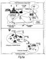
- Figure 5illustrates a number of applications for relay stations.
- the coverage provided by a relay stationmay be in-fill to allow access to the communication network for mobile stations which may otherwise be in the shadow of other objects or otherwise unable to receive a signal of sufficient strength from the base station despite being within the normal range of the base station.
- Range extensionis also shown, in which a relay station allows access when a mobile station is outside the normal data transmission range of a base station.
- in-fill shown at the top right of Figure 5is positioning of a nomadic relay station to allow penetration of coverage within a building that could be above, at, or below ground level.
- Relaysmay also be used in conjunction with advanced transmission techniques to enhance gain of the communications system as explained below.
- Multi-hop systemsare suitable for use with multi-carrier transmission.
- a multi-carrier transmission systemsuch as FDM (frequency division multiplex), OFDM (orthogonal frequency division multiplex) or DMT (discrete multi-tone)
- FDMfrequency division multiplex
- OFDMorthogonal frequency division multiplex
- DMTdiscrete multi-tone
- a single data streamis modulated onto N parallel sub-carriers, each sub-carrier signal having its own frequency range. This allows the total bandwidth (i.e. the amount of data to be sent in a given time interval) to be divided over a plurality of sub-carriers thereby increasing the duration of each data symbol. Since each sub-carrier has a lower information rate, multi-carrier systems benefit from enhanced immunity to channel induced distortion compared with single carrier systems.
- the channel distortion correction entity within a multicarrier receivercan be of significantly lower complexity of its counterpart within a single carrier receiver when the system bandwidth is in excess of the coherence bandwidth of the channel.
- Orthogonal frequency division multiplexingis a modulation technique that is based on FDM.
- An OFDM systemuses a plurality of sub-carrier frequencies which are orthogonal in a mathematical sense so that the sub-carriers spectra may overlap without interference due to the fact they are mutually independent.
- the orthogonality of OFDM systemsremoves the need for guard band frequencies and thereby increases the spectral efficiency of the system.
- OFDMhas been proposed and adopted for many wireless systems. It is currently used in Asymmetric Digital Subscriber Line (ADSL) connections, in some wireless LAN applications (such as WiFi devices based on the IEEE802.11a/g standard), and in wireless MAN applications such as WiMAX (based on the IEEE 802.16 standard).
- ADSLAsymmetric Digital Subscriber Line
- OFDMis often used in conjunction with channel coding, an error correction technique, to create coded orthogonal FDM or COFDM.
- COFDMis now widely used in digital telecommunications systems to improve the performance of an OFDM based system in a multipath environment where variations in the channel distortion can be seen across both subcarriers in the frequency domain and symbols in the time domain.
- the systemhas found use in video and audio broadcasting, such as DVB and DAB, as well as certain types of computer networking technology.
- an OFDM symbolis the composite signal of all N sub-carrier signals.
- the sub-carrier vector in (1) onto which each of the source signals is modulated c ⁇ C n , c(c 0 , c 1 ..c N-1 ) is a vector of N constellation symbols from a finite constellation.
- DFTDiscrete Fourier Transform
- FFTFast Fourier Transform
- OFDMAOrthogonal Frequency Division Multiple Access
- FDDfrequency division duplexing
- TDDtime division duplexing
- Both approaches (TDD & FDD)have their relative merits and are both well used techniques for single hop wired and wireless communication systems.
- IEEE802.16 standardincorporates both an FDD and TDD mode.
- Figure 6illustrates the single hop TDD frame structure used in the OFDMA physical layer mode of the IEEE802.16 standard (WiMAX).
- Each frameis divided into DL and UL subframes, each being a discrete transmission interval. They are separated by Transmit/Receive and Receive/Transmit Transition Guard interval (TTG and RTG respectively).
- TTG and RTGTransmit/Receive and Receive/Transmit Transition Guard interval respectively.
- Each DL subframestarts with a preamble followed by the Frame Control Header (FCH), the DL-MAP, and the UL-MAP.
- FCHFrame Control Header
- DL-MAPDL-MAP
- UL-MAPUL-MAP
- Simultaneous DL allocationscan be broadcast, multicast and unicast and they can also include an allocation for another BS rather than a serving BS.
- Simultaneous ULscan be data allocations and ranging or bandwidth requests.
- XP002573791discloses frame structures for mobile multihop communication systems, in which transmission between a base station and a mobile station via a plurality of relay stations takes place in a single downlink or uplink subframe.
- EP1324509discloses a packet transmission control method.
- the object in this documentis to control interference in a permissible range by applying the CDMA system to signal collision in the conventional CSMA and TDMA base multi-hop systems and to relax the hidden terminal problem and others to enhance the throughput of the entire system by grouping of channel groups in multihop transmission and by control of transmission based on an interference level from another station.
- a nodeWhen a node is required to support two independent links to two different nodes, e.g. a relay station communicating with a basestation and a mobile, the existing TDD or FDD frame structures require some modification in order to make realization of the relay practical.
- Embodiments of the inventionprovide a frame structure for a multihop communication system that is an extension of the standard TDD frame structure (see IEEE802.16 standard for an example) that provides support for any number of hops in the system.
- the proposed frame structurehas numerous benefits, as described later in this description.
- the proposed frame structuremakes the assumption that the control information originating from the head node that controls the overall medium access is receivable by all subordinate nodes operating in the network. Also it is assumed that the modified frame TDD structure should be able to enable legacy mobile devices that have no knowledge of a relay station to operate within the system.
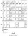
- the proposed generic TDD frame structureis shown in Figure 1 .
- Zone Number Label Description 1P Preamble or synchronization sequence transmissions for cell identification 2 MAP Frame format description (zone boundaries, allocations within the zones, etc) 3 BS-RS / BS-MS / RS-RS/MS BS to RS transmission zone. Can also be used for BS to MS transmission if spatial division multiple access is supported (i.e. the same transmission resource can be used to communicate with more than one entity). Can also be used for RS to RS or MS transmission. 4 BS-MS BS to MS transmission zone. RS is not active during this period, it is processing any received information and turning around prior to transmission. 5 BS-MS / RS-RS/MS RS to RS or MS transmission zone.
- FIG. 2illustrates the operation of the BS, RS and MS in terms of its activity within each of the zones described in Table 1 when the MS is connected to the BS via two RSs (RS1 & RS2).
- RS1uses zones (5) and (7) to communicate with RS2 as zones (3) and (9) are used to communicate with the BS. Also this approach enables the possibility of performing relaying of information across the first hop within the same frame.
- RS2then makes use of zones (3) and (9) to communication with any MSs (or further RS). If a third RS existed (RS3), then it would use zones (5) and (7) to communicate with any MSs or further RSs.
- Figure 3indicates one particular realisation of the proposed frame structure in terms of how different user types may be allocated to the various zone types.
- Such programs embodying the present inventionmay be stored on computer-readable media, or could, for example, be in the form of one or more signals.
- signalsmay be data signals downloadable from an Internet website, or provided on a carrier signal, or in any other form.
Landscapes
- Engineering & Computer Science (AREA)
- Signal Processing (AREA)
- Computer Networks & Wireless Communication (AREA)
- Mobile Radio Communication Systems (AREA)
- Radio Relay Systems (AREA)
Description
- Currently there exists significant interest in the use of multihop techniques in packet based radio and other communication systems, where it is purported that such techniques will enable both extension in coverage range and increase in system capacity (throughput).
- In a multi-hop communication system, communication signals are sent in a communication direction along a communication path (C) from a source apparatus to a destination apparatus via one or more intermediate apparatuses.
Figure 4 illustrates a single-cell two-hop wireless communication system comprising a base station BS (known in the context of 3G communication systems as node-B NB) a relay node RN (also known as a relay station RS) and a user equipment UE (also known as mobile station MS). In the case where signals are being transmitted on the downlink (DL) from a base station to a destination user equipment (UE) via the relay node (RN), the base station comprises the source station (S) and the user equipment comprises the destination station (D). In the case where communication signals are being transmitted on the uplink (UL) from a user equipment (UE), via the relay node, to the base station, the user equipment comprises the source station and the base station comprises the destination station. The relay node is an example of an intermediate apparatus (I) and comprises: a receiver, operable to receive data from the source apparatus; and a transmitter, operable to transmit this data, or a derivative thereof, to the destination apparatus. - Simple analogue repeaters or digital repeaters have been used as relays to improve or provide coverage in dead spots. They can either operate in a different transmission frequency band from the source station to prevent interference between the source transmission and the repeater transmission, or they can operate at a time when there is no transmission from the source station.
Figure 5 illustrates a number of applications for relay stations. For fixed infrastructure, the coverage provided by a relay station may be in-fill to allow access to the communication network for mobile stations which may otherwise be in the shadow of other objects or otherwise unable to receive a signal of sufficient strength from the base station despite being within the normal range of the base station. Range extension is also shown, in which a relay station allows access when a mobile station is outside the normal data transmission range of a base station. One example of in-fill shown at the top right ofFigure 5 is positioning of a nomadic relay station to allow penetration of coverage within a building that could be above, at, or below ground level.- Other applications are nomadic relay stations which are brought into effect for temporary cover, providing access during events or emergencies/disasters. A final application shown in the bottom right of
Figure 5 provides access to a network using a relay positioned on a vehicle. - Relays may also be used in conjunction with advanced transmission techniques to enhance gain of the communications system as explained below.
- It is known that the occurrence of propagation loss, or pathloss, due to the scattering or absorption of a radio communication as it travels through space, causes the strength of a signal to diminish. Factors which influence the pathloss between a transmitter and a receiver include: transmitter antenna height, receiver antenna height, carrier frequency, clutter type (urban, sub-urban, rural), details of morphology such as height, density, separation, terrain type (hilly, flat). The pathloss L (dB) between a transmitter and a receiver can be modelled by:

- Where d (metres) is the transmitter-receiver separation, b(db) and n are the pathloss parameters and the absolute pathloss is given byl = 10(L/10).
- The sum of the absolute path losses experienced over the indirect link SI + ID may be less than the pathloss experienced over the direct link SD. In other words it is possible for:

- Splitting a single transmission link into two shorter transmission segments therefore exploits the non-linear relationship between pathloss verses distance. From a simple theoretical analysis of the path loss using equation (A), it can be appreciated that a reduction in the overall path loss (and therefore an improvement, or gain, in signal strength and thus data throughput) can be achieved if a signal is sent from a source apparatus to a destination apparatus via an intermediate apparatus (e.g. relay node), rather than being sent directly from the source apparatus to the destination apparatus. If implemented appropriately, multi-hop communication systems can allow for a reduction in the transmit power of transmitters which facilitate wireless transmissions, leading to a reduction in interference levels as well as decreasing exposure to electromagnetic emissions. Alternatively, the reduction in overall pathloss can be exploited to improve the received signal quality at the receiver without an increase in the overall radiated transmission power required to convey the signal.
- Multi-hop systems are suitable for use with multi-carrier transmission. In a multi-carrier transmission system, such as FDM (frequency division multiplex), OFDM (orthogonal frequency division multiplex) or DMT (discrete multi-tone), a single data stream is modulated onto N parallel sub-carriers, each sub-carrier signal having its own frequency range. This allows the total bandwidth (i.e. the amount of data to be sent in a given time interval) to be divided over a plurality of sub-carriers thereby increasing the duration of each data symbol. Since each sub-carrier has a lower information rate, multi-carrier systems benefit from enhanced immunity to channel induced distortion compared with single carrier systems. This is made possible by ensuring that the transmission rate and hence bandwidth of each subcarrier is less than the coherence bandwidth of the channel. As a result, the channel distortion experienced on a signal subcarrier is frequency independent and can hence be corrected by a simple phase and amplitude correction factor. Thus the channel distortion correction entity within a multicarrier receiver can be of significantly lower complexity of its counterpart within a single carrier receiver when the system bandwidth is in excess of the coherence bandwidth of the channel.
- Orthogonal frequency division multiplexing (OFDM) is a modulation technique that is based on FDM. An OFDM system uses a plurality of sub-carrier frequencies which are orthogonal in a mathematical sense so that the sub-carriers spectra may overlap without interference due to the fact they are mutually independent. The orthogonality of OFDM systems removes the need for guard band frequencies and thereby increases the spectral efficiency of the system. OFDM has been proposed and adopted for many wireless systems. It is currently used in Asymmetric Digital Subscriber Line (ADSL) connections, in some wireless LAN applications (such as WiFi devices based on the IEEE802.11a/g standard), and in wireless MAN applications such as WiMAX (based on the IEEE 802.16 standard). OFDM is often used in conjunction with channel coding, an error correction technique, to create coded orthogonal FDM or COFDM. COFDM is now widely used in digital telecommunications systems to improve the performance of an OFDM based system in a multipath environment where variations in the channel distortion can be seen across both subcarriers in the frequency domain and symbols in the time domain. The system has found use in video and audio broadcasting, such as DVB and DAB, as well as certain types of computer networking technology.
- In an OFDM system, a block of N modulated parallel data source signals is mapped to N orthogonal parallel sub-carriers by using an Inverse Discrete or Fast Fourier Transform algorithm (IDFT/IFFT) to form a signal known as an OFDM symbol in the time domain at the transmitter. Thus, an OFDM symbol is the composite signal of all N sub-carrier signals. An OFDM symbol can be represented mathematically as:

where Δf is the sub-carrier separation in Hz, Ts = 1/Δf is symbol time interval in seconds, and cn are the modulated source signals. The sub-carrier vector in (1) onto which each of the source signals is modulated c ∈ Cn, c = (c0, c1..cN-1) is a vector of N constellation symbols from a finite constellation. At the receiver, the received time-domain signal is transformed back to frequency domain by applying Discrete Fourier Transform (DFT) or Fast Fourier Transform (FFT) algorithm. - OFDMA (Orthogonal Frequency Division Multiple Access) is a multiple access variant of OFDM. It works by assigning a subset of sub-carriers, to an individual user. This allows simultaneous transmission from several users leading to better spectral efficiency. However, there is still the issue of allowing bi-directional communication, that is, in the uplink and download directions, without interference.
- In order to enable bi-directional communication between two nodes, two well known different approaches exist for duplexing the two (forward or download and reverse or uplink) communication links to overcome the physical limitation that a device cannot simultaneously transmit and receive on the same resource medium. The first, frequency division duplexing (FDD), involves operating the two links simultaneously but on different frequency bands by subdividing the transmission medium into two distinct bands, one for forward link and the other for reverse link communications. The second, time division duplexing (TDD), involves operating the two links on the same frequency band, but subdividing the access to the medium in time so that only the forward or the reverse link will be utilizing the medium at any one point in time. Both approaches (TDD & FDD) have their relative merits and are both well used techniques for single hop wired and wireless communication systems. For example the IEEE802.16 standard incorporates both an FDD and TDD mode.
- As an example,
Figure 6 illustrates the single hop TDD frame structure used in the OFDMA physical layer mode of the IEEE802.16 standard (WiMAX). - Each frame is divided into DL and UL subframes, each being a discrete transmission interval. They are separated by Transmit/Receive and Receive/Transmit Transition Guard interval (TTG and RTG respectively). Each DL subframe starts with a preamble followed by the Frame Control Header (FCH), the DL-MAP, and the UL-MAP.
- The FCH contains the DL Frame Prefix (DLFP) to specify the burst profile and the length of the DL-MAP. The DLFP is a data structure transmitted at the beginning of each frame and contains information regarding the current frame; it is mapped to the FCH.
- Simultaneous DL allocations can be broadcast, multicast and unicast and they can also include an allocation for another BS rather than a serving BS. Simultaneous ULs can be data allocations and ranging or bandwidth requests.
- Gang Shen, Xiaobing Leng, Wei Zou, WeiNi, KaibinZhang, Shan Jin, Torsten Fahldieck, Roland Muenzner: "Recommendations on IEEE 802.16j" IEEE 802.16j contribution by Alcatel Research & Innovation, 8 May 2006, XP002573791 discloses frame structures for mobile multihop communication systems, in which transmission between a base station and a mobile station via a plurality of relay stations takes place in a single downlink or uplink subframe.
EP1324509 discloses a packet transmission control method. The object in this document is to control interference in a permissible range by applying the CDMA system to signal collision in the conventional CSMA and TDMA base multi-hop systems and to relax the hidden terminal problem and others to enhance the throughput of the entire system by grouping of channel groups in multihop transmission and by control of transmission based on an interference level from another station. A multihop relay station calculates a desired signal level, for example, from an interference level at its own station of a packet sent from a mobile station, and notifies the mobile station of the desired signal level; and the mobile station calculates a transmission power amount of a packet from the desired signal level, determines whether the packet is transmissible to the station as a source of the desired signal level, on the basis of the transmission power amount, and transmits the packet by a power of the transmission power amount to the source station determined as a packet-transmissible station. On this occasion, an interference signal is weakened by assignment ofchannel groups - The invention is defined in the independent claims, to which reference should now be made. Advantageous embodiments are set out in the sub claims.
- Preferred features of the present invention will now be described, purely by way of example, with reference to the accompanying drawings, in which:-
Figure 1 shows a frame structure;Figure 2 shows node activity within each zone;Figure 3 shows an example of zone usage within one cell;Figure 4 shows a single-cell two-hop wireless communication system;Figure 5 shows applications of relay stations; andFigure 6 shows a single hop TDD frame structure used in the OFDMA physical layer mode of the IEEE 802.16 standard.- When a node is required to support two independent links to two different nodes, e.g. a relay station communicating with a basestation and a mobile, the existing TDD or FDD frame structures require some modification in order to make realization of the relay practical.
- Embodiments of the invention provide a frame structure for a multihop communication system that is an extension of the standard TDD frame structure (see IEEE802.16 standard for an example) that provides support for any number of hops in the system. The proposed frame structure has numerous benefits, as described later in this description.
- The proposed frame structure makes the assumption that the control information originating from the head node that controls the overall medium access is receivable by all subordinate nodes operating in the network. Also it is assumed that the modified frame TDD structure should be able to enable legacy mobile devices that have no knowledge of a relay station to operate within the system.
- The proposed generic TDD frame structure is shown in
Figure 1 . - It is composed of a number of transmission and reception zones for both the downlink and uplink sub-frames. The zone types are either:
- B Broadcast of control related information such as: synchronization sequences, commands, information and details of the structure or layout of the frame.
- C Dedicated control information that is transmitted in a non-broadcast zone (i.e. either to individual or a group of receivers)
- T Dedicated user-data transmission
- The 9 different zones are described in Table 1.
Table 1. Description of the zones. Zone Number Label Description 1 P Preamble or synchronization sequence transmissions for cell identification 2 MAP Frame format description (zone boundaries, allocations within the zones, etc) 3 BS-RS / BS-MS / RS-RS/MS BS to RS transmission zone. Can also be used for BS to MS transmission if spatial division multiple access is supported (i.e. the same transmission resource can be used to communicate with more than one entity). Can also be used for RS to RS or MS transmission. 4 BS-MS BS to MS transmission zone. RS is not active during this period, it is processing any received information and turning around prior to transmission. 5 BS-MS / RS-RS/MS RS to RS or MS transmission zone. Can also be used by the BS to transmit to MSs that do not experience significant levels of interference from RS transmissions. 6 MS-BS / MS-RS MS control information transmission zone. Information can be received by both the RS and the BS. Control information can be information or requests from the MS. 7 MS-BS / MS/RS-RS MS or RS to RS transmission zone. Can also be used by MSs who do not cause interference to the RS to transmit to the BS. 8 MS-BS MS to BS transmission zone. RS is not actively transmitting or receiving during this period; it is processing any received information prior to turning around. 9 RS-BS / MS-BS / MS/RS-RS RS to BS transmission zone. Can also be used for MS to BS transmission if spatial division multiple access is supported (i.e. the same transmission resource can be used to communicate with more than one entity). Can also be used for MS or RS to RS communication. Figure 2 illustrates the operation of the BS, RS and MS in terms of its activity within each of the zones described in Table 1 when the MS is connected to the BS via two RSs (RS1 & RS2). Note that RS1 uses zones (5) and (7) to communicate with RS2 as zones (3) and (9) are used to communicate with the BS. Also this approach enables the possibility of performing relaying of information across the first hop within the same frame. RS2 then makes use of zones (3) and (9) to communication with any MSs (or further RS). If a third RS existed (RS3), then it would use zones (5) and (7) to communicate with any MSs or further RSs.- Note that relaying across the first two hops occurs within one frame. However, relaying over three hops introduces an extra frame delay. In the general case of N hops, it is found that the extra latency introduced through relaying is given by the following expression:

Figure 3 indicates one particular realisation of the proposed frame structure in terms of how different user types may be allocated to the various zone types.- In this case there are six link types identified (A, C-G). A description of the zones used on each link in this example is given in Table 2.
Table 2. Description of example of zone usage within one cell. Link DL Zone Usage UL Zone Usage Comments (A) (1), (2), (5) (6), (7) MS and RS are spatially separated and therefore significant interference isolation exists. (C) (1), (2), (3), (5) (6), (7), (9) RS1 receives data in (3) and (7) and then transmits in (5) and (9). (D) (1), (2), (5) (6), (7) MS communicates with BS via RS1. Transmission to the RS happens at the beginning of the UL subframe to allow sufficient RS relay processing time. (E) (1), (2), (4) (6), (8) MSs that communicate directly with the BS that are not isolated from the RS use zones (4) & (8) to prevent RS interference from impairing link performance. (F) (1), (2), (5) (6), (7) RS1 and RS2 communicate using the same zones that RS1 uses to communicate with the MSs connected via RS1. (G) (1), (2), (3) (6), (9) RS2 communicates with MS using zones (3) and (9). - In summary the benefits of the invention embodiments are:
- o Enables the construction and operation of simple, low cost relays that do not need to generate any control information or perform scheduling
- o Maximizes spectral efficiency by making sure that the BS does not have any time in the frame when it is idle
- o Minimal latency: latency in units of frames is 0 for 1 or 2 hops, 1 for 3 or 4 hops, 2 for 5 or 6 hops, 3 for 7 or 8 hops, etc.
- o Enables the system to potentially provide transparent operation to a legacy single-hop TDD user
- o The possibility to further improve spectral efficiency through using SDMA based techniques to enable the same transmission resource (frequency & time) to be used between the BS and the RSs and MSs within a cell.
- o Is extendable to any number of hops
- Embodiments of the present invention may be implemented in hardware, or as software modules running on one or more processors, or on a combination thereof. That is, those skilled in the art will appreciate that a microprocessor or digital signal processor (DSP) may be used in practice to implement some or all of the functionality of a transmitter embodying the present invention. The invention may also be embodied as one or more device or apparatus programs (e.g. computer programs and computer program products) for carrying out part or all of any of the methods described herein.
- Such programs embodying the present invention may be stored on computer-readable media, or could, for example, be in the form of one or more signals. Such signals may be data signals downloadable from an Internet website, or provided on a carrier signal, or in any other form.


Claims (21)
- A transmission method for use in a multi-hop wireless communication system, the system comprising a source apparatus, a destination apparatus and two or more intermediate apparatuses, said source apparatus being operable to transmit information along a series of links forming a communication path extending from the source apparatus to the destination apparatus via each intermediate apparatus, and each intermediate apparatus being operable to receive information from a previous apparatus along the path and to transmit the received information to a subsequent apparatus along the path, the system having access to a time-frequency format for use in assigning available transmission frequency bandwidth during a sub-frame period, said format defining a plurality of transmission windows within such a sub-frame period, each window occupying a different part of that sub-frame period and having a frequency bandwidth profile extending over substantially the entire transmission frequency bandwidth over its part of that sub-frame period, each said window being assignable for such a sub-frame period to one of said apparatuses for use in transmission, the format including a particular transmission window (3,7) and a subsequent transmission window (5,9) and the method comprising:employing said format for more than one such sub-frame period to transmit information along at least three consecutive said links as a set of successive transmission signals, link by link, each said signal being transmitted in an available transmission window of said sub-frame periods; the method further comprising:prior to said transmission, employing said format:to assign the particular transmission window (3,7) of a first sub-frame period to a first said apparatus along said consecutive links for transmission of the information to a second said apparatus along said consecutive links, said second apparatus being one subsequent link along the path from the first apparatus,to assign the subsequent transmission window (5,9) of the first sub-frame period to the second apparatus for transmission of the information to a third said apparatus along said consecutive links, said third apparatus being one subsequent link along the path from the second apparatus, andto assign the particular transmission window (3,7) of a second sub-frame period being the next such sub-frame period after said first sub-frame period to said third apparatus for transmission of the information to a fourth said apparatus along said consecutive links, said fourth apparatus being one subsequent link along the path from the third apparatus.
- The transmission method according to any of the preceding claims, wherein
at least two of said signals are transmitted during the same said sub-frame period such that said information is transmitted along said consecutive links in fewer sub-frame periods than said number of consecutive links. - The transmission method according to any of the preceding claims, wherein the system comprises at least three said intermediate apparatuses, the method further comprising:prior to said transmission, employing said format to assign the subsequent transmission window (5,9) of the second sub-frame period to the fourth apparatus for transmission of the information to a fifth said apparatus along said consecutive links, said fifth apparatus being one subsequent link along the path from the fourth apparatus.
- The transmission method according to any of the preceding claims, wherein said particular and subsequent transmission windows of each of said first and second sub-frame periods are either side in time of a further transmission window (4,8) of the sub-frame period concerned.
- The transmission method according to claim 4, further comprising:performing processing in said second and fourth apparatus, during the part of the sub-frame period corresponding to the further transmission window (4,8) of the sub-frame period concerned, so as to configure the information for transmission in the subsequent transmission window (5,9) of that sub-frame period based upon the information received in the particular transmission window (3,7) of that sub-frame period.
- The transmission method according to any preceding claim, wherein said communication path is an indirect communication path, and wherein the system comprises at least a further destination apparatus, and wherein said source apparatus or any said intermediate apparatus is operable to transmit information directly to the or each further destination apparatus along a corresponding single link forming a direct communication path.
- The transmission method according to any preceding claim, comprising employing a space division multiple access technique in one or more of said transmission windows of said sub-frame periods.
- The transmission method according to any preceding claim, wherein the time-frequency format is a format for a downlink or uplink sub-frame in a time-division-duplex communication system.
- The transmission method according to any preceding claim, wherein said system is an OFDM or OFDMA system, and wherein the time-frequency format is a format for an OFDM or OFDMA downlink or uplink sub-frame of an OFDM or OFDMA time-division-duplex frame.
- The transmission method according to any preceding claim, wherein each said transmission window comprises a region in an OFDM or OFDMA frame structure.
- The transmission method according to any preceding claim, wherein each said transmission window comprises a zone in an OFDM or OFDMA frame structure.
- The transmission method according to any preceding claim, wherein said source apparatus is a base station.
- The transmission method according to any preceding claim, wherein said source apparatus is a user terminal.
- The transmission method according to any preceding claim, wherein the or each destination apparatus is a base station.
- The transmission method according to any preceding claim, wherein the or each destination apparatus is a user terminal.
- The transmission method according to any preceding claim, wherein each said intermediate apparatus is a relay station.
- A multi-hop wireless communication system, the system comprising:a source apparatus, a destination apparatus and two or more intermediate apparatuses, said source apparatus being operable to transmit information along a series of links forming a communication path extending from the source apparatus to the destination apparatus via each intermediate apparatus, and each intermediate apparatus being operable to receive information from a previous apparatus along the path and to transmit the received information to a subsequent apparatus along the path;format-access means operable to access a time-frequency format for use in assigning available transmission frequency bandwidth during a discrete sub-frame period, said format defining a plurality of transmission windows within such a sub-frame period, each window occupying a different part of that interval and having a frequency bandwidth profile extending over substantially the entire transmission frequency bandwidth over its part of that sub-frame period, each said window being assignable for such a sub-frame period to one of said apparatuses for use in transmission, the format including a particular transmission window (3,7) and a subsequent transmission window; (5,9) andtransmission means operable to employ said format for more than one such sub-frame period to transmit information along at least three consecutive said links as a set of successive transmission signals, link by link, each said signal being transmitted in an available transmission window of said sub-frame periods, whereinthe system is operable, prior to said transmission, to employ said format:to assign the particular transmission window (3,7) of a first sub-frame period to a first said apparatus along said consecutive links for transmission of the information to a second said apparatus along said consecutive links, said second apparatus being one subsequent link along the path from the first apparatus,to assign the subsequent transmission window (5,9) of the first sub-frame period to the second apparatus for transmission of the information to a third said apparatus along said consecutive links, said third apparatus being one subsequent link along the path from the second apparatus, andto assign the particular transmission window (3,7) of a second sub-frame period being the next such sub-frame period after said first sub-frame period to said third apparatus for transmission of the information to a fourth said apparatus along said consecutive links, said fourth apparatus being one link along the path from the third apparatus.
- A suite of computer programs which, when executed on computing devices of a multi-hop wireless communication system, causes the system to carry out a transmission method according to any of the preceding method claims.
- A particular intermediate apparatus for use in a multi-hop wireless communication system, the system further comprising a source apparatus, at least one other intermediate apparatus, and a destination apparatus, said source apparatus being operable to transmit information along a series of links forming a communication path extending from the source apparatus to the destination apparatus via each intermediate apparatus, and each intermediate apparatus being operable to receive information from a previous apparatus along the path and to transmit the received information to a subsequent apparatus along the path, the particular intermediate apparatus comprising:format-access means operable to access a time-frequency format for use in assigning available transmission frequency bandwidth during a discrete sub-frame period, said format defining a plurality of transmission windows within such a sub-frame period, each window occupying a different part of that sub-frame period and having a frequency bandwidth profile extending over substantially the entire transmission frequency bandwidth over its part of that subframe, each said window being assignable for such a sub-frame period to one of said apparatuses for use in transmission to transmit information along at least three consecutive said links, the format including a particular transmission window (3,7) and a subsequent transmission window (5,9); andtransceiver means operable to employ said format for more than one such sub-frame period to receive information in the subsequent transmission window (5,9) of a sub-frame period from a second apparatus along said consecutive links, and to transmit said information in a particular transmission window (3,7) during the next said sub-frame period to a fourth said apparatus along said consecutive links, the information having been transmitted by a first said apparatus along said consecutive links to the second said apparatus along said consecutive links in the particular transmission window (3,7) of the sub-frame period, said second apparatus being one subsequent link along the path from the first apparatus, said particular intermediate apparatus being one subsequent link along the path from the second apparatus, and said fourth apparatus being one subsequent link along the path from the particular intermediate apparatus.
- A method in a particular intermediate apparatus of a multi-hop wireless communication system, the system further comprising a source apparatus, at least one other intermediate apparatus, and a destination apparatus, said source apparatus being operable to transmit information along a series of links forming a communication path extending from the source apparatus to the destination apparatus via each intermediate apparatus, and each intermediate apparatus being operable to receive information from a previous apparatus along the path and to transmit the received information to a subsequent apparatus along the path, the method comprising:accessing a time-frequency format for use in assigning available transmission frequency bandwidth during a discrete sub-frame period, said format defining a plurality of transmission windows within such a sub-frame period, each window occupying a different part of that sub-frame period and having a frequency bandwidth profile extending over substantially the entire transmission frequency bandwidth over its part of that sub-frame period, each said window being assignable for such a sub-frame period to one of said apparatuses for use in transmission to transmit information along at least three consecutive said links, the format including a particular transmission window (3,7) and a subsequent transmission window (5,9); andemploying said format for more than one such sub-frame period to receive information in a subsequent transmission window (5,9) of a sub-frame period from a second apparatus along said consecutive links, and to transmit said information in the particular transmission window (3,7) during the next said sub-frame period to a fourth said apparatus along said consecutive links, the information having been transmitted by a first said apparatus along said consecutive links to the second said apparatus along said consecutive links in the particular transmission window (3,7) of the sub-frame period, said second apparatus being one subsequent link along the path from the first apparatus, said particular intermediate apparatus being one subsequent link along the path from the second apparatus, and said fourth apparatus being one subsequent link along the path from the particular intermediate apparatus.
- A computer program which when executed on a computing device of a particular intermediate apparatus of a multi-hop wireless communication system, causes the particular intermediate apparatus to carry out a transmission method according to claim 20.
Priority Applications (1)
| Application Number | Priority Date | Filing Date | Title |
|---|---|---|---|
| EP09173854AEP2146463A3 (en) | 2006-08-18 | 2007-07-31 | Multi-hop wireless communication system and method |
Applications Claiming Priority (1)
| Application Number | Priority Date | Filing Date | Title |
|---|---|---|---|
| GB0616479AGB2440984A (en) | 2006-08-18 | 2006-08-18 | Wireless multi-hop communication system |
Related Child Applications (2)
| Application Number | Title | Priority Date | Filing Date |
|---|---|---|---|
| EP09173854ADivisionEP2146463A3 (en) | 2006-08-18 | 2007-07-31 | Multi-hop wireless communication system and method |
| EP09173854.2Division-Into | 2009-10-22 |
Publications (3)
| Publication Number | Publication Date |
|---|---|
| EP1890446A2 EP1890446A2 (en) | 2008-02-20 |
| EP1890446A3 EP1890446A3 (en) | 2010-05-12 |
| EP1890446B1true EP1890446B1 (en) | 2012-12-05 |
Family
ID=37081241
Family Applications (2)
| Application Number | Title | Priority Date | Filing Date |
|---|---|---|---|
| EP09173854AWithdrawnEP2146463A3 (en) | 2006-08-18 | 2007-07-31 | Multi-hop wireless communication system and method |
| EP07113552ANot-in-forceEP1890446B1 (en) | 2006-08-18 | 2007-07-31 | Multi-hop wireless communication |
Family Applications Before (1)
| Application Number | Title | Priority Date | Filing Date |
|---|---|---|---|
| EP09173854AWithdrawnEP2146463A3 (en) | 2006-08-18 | 2007-07-31 | Multi-hop wireless communication system and method |
Country Status (7)
| Country | Link |
|---|---|
| US (2) | US8085652B2 (en) |
| EP (2) | EP2146463A3 (en) |
| JP (2) | JP4978368B2 (en) |
| KR (1) | KR100938333B1 (en) |
| CN (2) | CN101820308A (en) |
| GB (1) | GB2440984A (en) |
| TW (2) | TW201015902A (en) |
Families Citing this family (36)
| Publication number | Priority date | Publication date | Assignee | Title |
|---|---|---|---|---|
| EP2144467B1 (en) | 2005-06-17 | 2011-11-23 | Fujitsu Limited | Systems and methods for power control in multi-hop communication system |
| EP1734666A1 (en) | 2005-06-17 | 2006-12-20 | Fujitsu Limited | Resource management in multi-hop communication system |
| EP1734667B1 (en) | 2005-06-17 | 2011-08-10 | Fujitsu Limited | Multi-hop communication system |
| EP1734665B1 (en) | 2005-06-17 | 2011-08-10 | Fujitsu Limited | Multi-hop communication system |
| GB2440981A (en)* | 2006-08-18 | 2008-02-20 | Fujitsu Ltd | Wireless multi-hop communication system |
| GB2440986A (en)* | 2006-08-18 | 2008-02-20 | Fujitsu Ltd | Wireless multi-hop communication system |
| EP2136587A3 (en)* | 2006-08-18 | 2012-05-02 | Fujitsu Limited | communication systems |
| GB2440982A (en)* | 2006-08-18 | 2008-02-20 | Fujitsu Ltd | Wireless multi-hop communication system |
| GB0616476D0 (en) | 2006-08-18 | 2006-09-27 | Fujitsu Ltd | Communication systems |
| KR100975732B1 (en)* | 2006-08-31 | 2010-08-12 | 삼성전자주식회사 | Method and system for transmitting resource allocation information in communication system |
| GB2441574A (en)* | 2006-09-08 | 2008-03-12 | Fujitsu Ltd | Network entry to a multi-hop wireless communication system |
| GB0619454D0 (en) | 2006-10-02 | 2006-11-08 | Fujitsu Ltd | Communication systems |
| GB0619455D0 (en) | 2006-10-02 | 2006-11-08 | Fujitsu Ltd | Communication system |
| GB2443464A (en) | 2006-11-06 | 2008-05-07 | Fujitsu Ltd | Signalling in a multi-hop communication systems |
| WO2008070007A2 (en)* | 2006-12-01 | 2008-06-12 | Nortel Networks Limited | Enhancing wimax performance with subscriber stations acting as ad hoc repeaters |
| GB2447883A (en) | 2007-03-02 | 2008-10-01 | Fujitsu Ltd | Bandwidth allocation in multi-hop wireless communication systems |
| GB2447635A (en) | 2007-03-19 | 2008-09-24 | Fujitsu Ltd | Scheduling qos communications between nodes within a predetermined time unit in wimax systems |
| US20100278123A1 (en)* | 2007-12-10 | 2010-11-04 | Nortel Networks Limited | Wireless communication frame structure and apparatus |
| US8488653B2 (en)* | 2008-02-04 | 2013-07-16 | Samsung Electronics Co., Ltd. | Cooperative communication system and method using the same |
| EP2157820A1 (en) | 2008-08-22 | 2010-02-24 | Fujitsu Limited | Methods and apparatus for operating a wireless communications system |
| US8971241B2 (en) | 2008-09-30 | 2015-03-03 | Qualcolmm Incorporated | Techniques for supporting relay operation in wireless communication systems |
| US9203564B2 (en) | 2008-10-20 | 2015-12-01 | Qualcomm Incorporated | Data transmission via a relay station in a wireless communication system |
| US9031053B2 (en)* | 2008-10-23 | 2015-05-12 | Qualcomm Incorporated | Method and apparatus for communicating in a relay communication network |
| US8634769B2 (en) | 2008-10-23 | 2014-01-21 | Qualcomm Incorporated | Data reception with interference cancellation in a relay communication network |
| KR101527977B1 (en)* | 2008-10-27 | 2015-06-15 | 엘지전자 주식회사 | Method of operating a repeater in a wireless communication system |
| CN101753184B (en)* | 2008-12-01 | 2013-05-08 | 中兴通讯股份有限公司 | Precoding feedback parameter adjusting method and device |
| US8243648B2 (en)* | 2008-12-19 | 2012-08-14 | Intel Corporation | Spatial reuse techniques with wireless network relays |
| US8472868B2 (en)* | 2009-05-06 | 2013-06-25 | Telefonaktiebolaget Lm Ericsson (Publ) | Method and apparatus for MIMO repeater chains in a wireless communication network |
| EP2434796A1 (en)* | 2009-05-19 | 2012-03-28 | Fujitsu Limited | Base station, relay station, communication system, and communication method |
| WO2011032580A1 (en)* | 2009-09-15 | 2011-03-24 | Nokia Siemens Networks Oy | Mobile communication device, network node and communication system for coordinated multipoint transmission comprising self-containment information of a channel-dependent attribute |
| CN101707788B (en)* | 2009-10-27 | 2014-04-02 | 北京邮电大学 | Differential pricing strategy based dynamic programming method of multilayer network services |
| US8553660B2 (en)* | 2010-01-03 | 2013-10-08 | Mitsubishi Electric Research Laboratories, Inc. | Cooperative relay communication in wireless OFDMA star networks |
| JP5386404B2 (en)* | 2010-02-26 | 2014-01-15 | 株式会社日立製作所 | Wireless communication system, base station, and network control apparatus |
| JP5249983B2 (en)* | 2010-04-05 | 2013-07-31 | 株式会社エヌ・ティ・ティ・ドコモ | Radio base station apparatus, mobile terminal apparatus and cell selection method |
| JP2011244061A (en)* | 2010-05-14 | 2011-12-01 | Sharp Corp | Radio communication system, transmission device, communication method and transmission method |
| GB2482761B (en)* | 2011-06-17 | 2015-12-23 | Airwave Solutions Ltd | Communications system, apparatus and method |
Citations (1)
| Publication number | Priority date | Publication date | Assignee | Title |
|---|---|---|---|---|
| EP1324509A2 (en)* | 2001-12-28 | 2003-07-02 | NTT DoCoMo, Inc. | Packet transmission control method |
Family Cites Families (49)
| Publication number | Priority date | Publication date | Assignee | Title |
|---|---|---|---|---|
| DE3403715A1 (en) | 1984-02-03 | 1985-08-08 | Licentia Patent-Verwaltungs-Gmbh, 6000 Frankfurt | DIGITAL CELL RADIO SYSTEM WITH TIME MULTIPLEX |
| US5719868A (en)* | 1995-10-05 | 1998-02-17 | Rockwell International | Dynamic distributed, multi-channel time division multiple access slot assignment method for a network of nodes |
| US6236647B1 (en) | 1998-02-24 | 2001-05-22 | Tantivy Communications, Inc. | Dynamic frame size adjustment and selective reject on a multi-link channel to improve effective throughput and bit error rate |
| US6370384B1 (en) | 1998-07-30 | 2002-04-09 | Airnet Communications Corporation | Frequency re-use planning for wireless communications system using wireless translating repeaters |
| US7006530B2 (en) | 2000-12-22 | 2006-02-28 | Wi-Lan, Inc. | Method and system for adaptively obtaining bandwidth allocation requests |
| US7158784B1 (en) | 2000-03-31 | 2007-01-02 | Aperto Networks, Inc. | Robust topology wireless communication using broadband access points |
| US6701129B1 (en) | 2000-09-27 | 2004-03-02 | Nortel Networks Limited | Receiver based adaptive modulation scheme |
| US6934554B2 (en)* | 2001-02-21 | 2005-08-23 | Nippon Telegraph And Telephone Corporation | Radio communication system |
| DE60117202D1 (en) | 2001-09-03 | 2006-04-20 | St Microelectronics Nv | A method and apparatus for estimating the speed of a mobile terminal in a wireless communication system |
| KR100487245B1 (en)* | 2001-11-28 | 2005-05-03 | 삼성전자주식회사 | Apparatus for minimizing transmission impossibility time due to compressed mode in mobile communication system using high speed downlink packet access scheme and method thereof |
| GB0200237D0 (en) | 2002-01-07 | 2002-02-20 | Imec Inter Uni Micro Electr | Wireless cellular network architecture |
| US7096274B1 (en) | 2002-02-12 | 2006-08-22 | 3Com Corporation | Optimum frame size predictor for wireless Local Area Network |
| JP2004040568A (en) | 2002-07-04 | 2004-02-05 | Denso Corp | Radio communications terminal |
| US7580394B2 (en) | 2002-11-27 | 2009-08-25 | Nokia Corporation | System and method for collision-free transmission scheduling in a network |
| US20040109428A1 (en) | 2002-12-09 | 2004-06-10 | Srikanth Krishnamurthy | Method and apparatus for resource allocation for multiple traffic classes in wireless ad-hoc networks |
| US7583619B2 (en) | 2002-12-16 | 2009-09-01 | Nortel Networks Limited | Wireless access communications network |
| CN100531167C (en)* | 2003-05-28 | 2009-08-19 | 艾利森电话股份有限公司 | Method and system for wireless communication networks using relaying |
| JP4289031B2 (en)* | 2003-06-06 | 2009-07-01 | ソニー株式会社 | Wireless communication system, wireless communication apparatus, wireless communication method, and computer program |
| CN1567869B (en)* | 2003-06-30 | 2010-05-05 | 叶启祥 | Interference control method capable of avoiding interference damage and increasing space reuse rate |
| US7903538B2 (en) | 2003-08-06 | 2011-03-08 | Intel Corporation | Technique to select transmission parameters |
| US7400856B2 (en) | 2003-09-03 | 2008-07-15 | Motorola, Inc. | Method and apparatus for relay facilitated communications |
| ATE441255T1 (en)* | 2003-12-30 | 2009-09-15 | Nokia Corp | ASYMMETRIC DATA CONNECTION COMMUNICATION SYSTEM WITH RELAY STATIONS |
| JP2005252677A (en)* | 2004-03-04 | 2005-09-15 | Kddi Corp | Base station, relay communication apparatus, and radio resource allocation method in multi-hop cellular system |
| US8023466B2 (en)* | 2004-06-22 | 2011-09-20 | Jianglei Ma | Soft handoff in OFDMA system |
| EP2993851B1 (en)* | 2004-06-24 | 2019-04-24 | Apple Inc. | Preambles in ofdma system |
| US20080144493A1 (en)* | 2004-06-30 | 2008-06-19 | Chi-Hsiang Yeh | Method of interference management for interference/collision prevention/avoidance and spatial reuse enhancement |
| JP2006033207A (en) | 2004-07-14 | 2006-02-02 | Nec Corp | Position information providing system, radio base station device, position information providing method used for both, and program thereof |
| US8019352B2 (en) | 2004-07-23 | 2011-09-13 | Wireless Valley Communications, Inc. | System, method, and apparatus for determining and using the position of wireless devices or infrastructure for wireless network enhancements |
| US7864659B2 (en) | 2004-08-02 | 2011-01-04 | Interdigital Technology Corporation | Quality control scheme for multiple-input multiple-output (MIMO) orthogonal frequency division multiplexing (OFDM) systems |
| JP4494134B2 (en)* | 2004-09-01 | 2010-06-30 | Kddi株式会社 | Wireless communication system, relay station apparatus and base station apparatus |
| ATE363189T1 (en) | 2004-09-13 | 2007-06-15 | Alcatel Lucent | ESTIMATION OF TRANSMISSION QUALITY IN A RADIO NETWORK |
| EP1794901B1 (en)* | 2004-09-30 | 2014-02-26 | LG Electronics Inc. | Method of receiving and transmitting data and estimating channel information in ofdm/ofdma mobile communications system |
| ES2383130T3 (en) | 2004-10-20 | 2012-06-18 | T-Mobile International Ag & Co. Kg | Cellular communications system for wide area radio with cells reinforced with repeaters |
| KR100810290B1 (en) | 2004-12-14 | 2008-03-07 | 삼성전자주식회사 | Method and system for allocation data burst in a wireless communication system |
| KR100584409B1 (en)* | 2004-12-29 | 2006-05-26 | 삼성전자주식회사 | Relay Communication Method for Orthogonal Frequency Division Multiple Access Based Cellular System |
| JP2006196985A (en)* | 2005-01-11 | 2006-07-27 | Kddi Corp | Media access control method in wireless system and media access control program of relay station |
| US8644130B2 (en) | 2005-03-18 | 2014-02-04 | Samsung Electronics Co., Ltd. | System and method for subcarrier allocation in a wireless multihop relay network |
| US7486928B2 (en) | 2005-04-14 | 2009-02-03 | Kddi Corporation | Methods and apparatus for wireless communications |
| US7813695B2 (en) | 2005-05-06 | 2010-10-12 | Telefonaktiebolaget L M Ericsson (Publ) | Mobile assisted relay selection in a telecommunications system |
| US20070230391A1 (en)* | 2005-05-12 | 2007-10-04 | Ofer Harpak | Device and Method for Exchanging Information Over Terrestrial and Satellite Links |
| JP2006319676A (en) | 2005-05-12 | 2006-11-24 | Oki Electric Ind Co Ltd | Frame transmission method, topology acquisition method, and wireless communication system |
| EP1734666A1 (en)* | 2005-06-17 | 2006-12-20 | Fujitsu Limited | Resource management in multi-hop communication system |
| US8169980B2 (en)* | 2005-07-11 | 2012-05-01 | Qualcomm Incorporated | Methods and apparatuses for interworking |
| KR20070031173A (en)* | 2005-09-14 | 2007-03-19 | 삼성전자주식회사 | Apparatus and method for supporting multiple links in a multihop relay cellular network |
| KR100855225B1 (en)* | 2005-09-28 | 2008-08-29 | 삼성전자주식회사 | Frame communication apparatus and method in broadband wireless access communication system using multi-hop relay method |
| KR100853422B1 (en) | 2006-01-03 | 2008-08-21 | 삼성전자주식회사 | Uplink Bandwidth Request and Allocation Method in Broadband Wireless Access Communication System Using Multi-hop Relay Method |
| EP2060038B1 (en)* | 2006-08-18 | 2016-06-29 | Fujitsu Limited | Radio resource management in multihop relay networks |
| GB2440986A (en)* | 2006-08-18 | 2008-02-20 | Fujitsu Ltd | Wireless multi-hop communication system |
| US8116256B2 (en)* | 2006-08-18 | 2012-02-14 | Fujitsu Limited | Wireless data frame structure among nodes |
- 2006
- 2006-08-18GBGB0616479Apatent/GB2440984A/ennot_activeWithdrawn
- 2007
- 2007-07-31TWTW098145565Apatent/TW201015902A/enunknown
- 2007-07-31EPEP09173854Apatent/EP2146463A3/ennot_activeWithdrawn
- 2007-07-31TWTW096127957Apatent/TWI366406B/ennot_activeIP Right Cessation
- 2007-07-31EPEP07113552Apatent/EP1890446B1/ennot_activeNot-in-force
- 2007-08-17CNCN200910265270Apatent/CN101820308A/enactivePending
- 2007-08-17USUS11/840,621patent/US8085652B2/ennot_activeExpired - Fee Related
- 2007-08-17KRKR1020070083059Apatent/KR100938333B1/ennot_activeExpired - Fee Related
- 2007-08-17CNCNA2007101419949Apatent/CN101127563A/enactivePending
- 2007-08-20JPJP2007214174Apatent/JP4978368B2/ennot_activeExpired - Fee Related
- 2009
- 2009-10-26JPJP2009245629Apatent/JP4852641B2/ennot_activeExpired - Fee Related
- 2009-12-29USUS12/649,053patent/US8179831B2/ennot_activeExpired - Fee Related
Patent Citations (1)
| Publication number | Priority date | Publication date | Assignee | Title |
|---|---|---|---|---|
| EP1324509A2 (en)* | 2001-12-28 | 2003-07-02 | NTT DoCoMo, Inc. | Packet transmission control method |
Non-Patent Citations (1)
| Title |
|---|
| FANG-CHING REN ET AL: "Recommendation on PMP Mode Compatible TDD Frame Structure", DOCUMENT NUMBER: IEEE C802.16MMR-05/027R1, pages 1 - 16, XP002575192, Retrieved from the Internet <URL:http://www.ieee802.org/16/sg/mmr/contrib/C80216mmr-05_027r1.pdf> [retrieved on 20100318]* |
Also Published As
| Publication number | Publication date |
|---|---|
| CN101127563A (en) | 2008-02-20 |
| JP2008048423A (en) | 2008-02-28 |
| JP2010063124A (en) | 2010-03-18 |
| GB2440984A (en) | 2008-02-20 |
| US20080043817A1 (en) | 2008-02-21 |
| US8179831B2 (en) | 2012-05-15 |
| CN101820308A (en) | 2010-09-01 |
| EP2146463A3 (en) | 2010-05-19 |
| KR100938333B1 (en) | 2010-01-22 |
| JP4978368B2 (en) | 2012-07-18 |
| TW201015902A (en) | 2010-04-16 |
| US8085652B2 (en) | 2011-12-27 |
| US20100103898A1 (en) | 2010-04-29 |
| KR20080016510A (en) | 2008-02-21 |
| EP1890446A2 (en) | 2008-02-20 |
| TW200822606A (en) | 2008-05-16 |
| GB0616479D0 (en) | 2006-09-27 |
| TWI366406B (en) | 2012-06-11 |
| JP4852641B2 (en) | 2012-01-11 |
| EP2146463A2 (en) | 2010-01-20 |
| EP1890446A3 (en) | 2010-05-12 |
Similar Documents
| Publication | Publication Date | Title |
|---|---|---|
| EP1890446B1 (en) | Multi-hop wireless communication | |
| EP1890416B1 (en) | Multi-hop wireless communication | |
| US7970347B2 (en) | Communication systems | |
| US7957257B2 (en) | Communication systems | |
| KR100983942B1 (en) | Communication method for use in multi-hop wireless communication system, multi-hop wireless communication system, base station apparatus, intermediate apparatus, and use equipment |
Legal Events
| Date | Code | Title | Description |
|---|---|---|---|
| PUAI | Public reference made under article 153(3) epc to a published international application that has entered the european phase | Free format text:ORIGINAL CODE: 0009012 | |
| AK | Designated contracting states | Kind code of ref document:A2 Designated state(s):AT BE BG CH CY CZ DE DK EE ES FI FR GB GR HU IE IS IT LI LT LU LV MC MT NL PL PT RO SE SI SK TR | |
| AX | Request for extension of the european patent | Extension state:AL BA HR MK YU | |
| PUAL | Search report despatched | Free format text:ORIGINAL CODE: 0009013 | |
| AK | Designated contracting states | Kind code of ref document:A3 Designated state(s):AT BE BG CH CY CZ DE DK EE ES FI FR GB GR HU IE IS IT LI LT LU LV MC MT NL PL PT RO SE SI SK TR | |
| AX | Request for extension of the european patent | Extension state:AL BA HR MK RS | |
| 17P | Request for examination filed | Effective date:20101108 | |
| 17Q | First examination report despatched | Effective date:20101209 | |
| AKX | Designation fees paid | Designated state(s):DE FR GB IT | |
| RIC1 | Information provided on ipc code assigned before grant | Ipc:H04L 12/56 20060101AFI20110405BHEP | |
| REG | Reference to a national code | Ref country code:DE Ref legal event code:R079 Ref document number:602007027102 Country of ref document:DE Free format text:PREVIOUS MAIN CLASS: H04L0012560000 Ipc:H04W0016260000 | |
| RIC1 | Information provided on ipc code assigned before grant | Ipc:H04W 16/26 20090101AFI20110512BHEP | |
| RTI1 | Title (correction) | Free format text:MULTI-HOP WIRELESS COMMUNICATION | |
| RIC1 | Information provided on ipc code assigned before grant | Ipc:H04L 12/56 20060101AFI20120217BHEP | |
| RIC1 | Information provided on ipc code assigned before grant | Ipc:H04W 16/02 20090101AFI20120502BHEP Ipc:H04L 5/00 20060101ALN20120502BHEP | |
| REG | Reference to a national code | Ref country code:DE Ref legal event code:R079 Ref document number:602007027102 Country of ref document:DE Free format text:PREVIOUS MAIN CLASS: H04W0016260000 Ipc:H04W0016020000 | |
| GRAP | Despatch of communication of intention to grant a patent | Free format text:ORIGINAL CODE: EPIDOSNIGR1 | |
| RIC1 | Information provided on ipc code assigned before grant | Ipc:H04W 16/02 20090101AFI20120619BHEP Ipc:H04L 5/00 20060101ALN20120619BHEP | |
| GRAS | Grant fee paid | Free format text:ORIGINAL CODE: EPIDOSNIGR3 | |
| GRAA | (expected) grant | Free format text:ORIGINAL CODE: 0009210 | |
| AK | Designated contracting states | Kind code of ref document:B1 Designated state(s):DE FR GB IT | |
| REG | Reference to a national code | Ref country code:GB Ref legal event code:FG4D | |
| REG | Reference to a national code | Ref country code:DE Ref legal event code:R096 Ref document number:602007027102 Country of ref document:DE Effective date:20130131 | |
| PGFP | Annual fee paid to national office [announced via postgrant information from national office to epo] | Ref country code:IT Payment date:20130418 Year of fee payment:7 | |
| PLBE | No opposition filed within time limit | Free format text:ORIGINAL CODE: 0009261 | |
| STAA | Information on the status of an ep patent application or granted ep patent | Free format text:STATUS: NO OPPOSITION FILED WITHIN TIME LIMIT | |
| PGFP | Annual fee paid to national office [announced via postgrant information from national office to epo] | Ref country code:DE Payment date:20130429 Year of fee payment:7 | |
| 26N | No opposition filed | Effective date:20130906 | |
| REG | Reference to a national code | Ref country code:DE Ref legal event code:R097 Ref document number:602007027102 Country of ref document:DE Effective date:20130906 | |
| GBPC | Gb: european patent ceased through non-payment of renewal fee | Effective date:20130731 | |
| REG | Reference to a national code | Ref country code:FR Ref legal event code:ST Effective date:20140331 | |
| PG25 | Lapsed in a contracting state [announced via postgrant information from national office to epo] | Ref country code:GB Free format text:LAPSE BECAUSE OF NON-PAYMENT OF DUE FEES Effective date:20130731 | |
| PG25 | Lapsed in a contracting state [announced via postgrant information from national office to epo] | Ref country code:FR Free format text:LAPSE BECAUSE OF NON-PAYMENT OF DUE FEES Effective date:20130731 | |
| REG | Reference to a national code | Ref country code:DE Ref legal event code:R119 Ref document number:602007027102 Country of ref document:DE | |
| PG25 | Lapsed in a contracting state [announced via postgrant information from national office to epo] | Ref country code:IT Free format text:LAPSE BECAUSE OF NON-PAYMENT OF DUE FEES Effective date:20140731 Ref country code:DE Free format text:LAPSE BECAUSE OF NON-PAYMENT OF DUE FEES Effective date:20150203 | |
| REG | Reference to a national code | Ref country code:DE Ref legal event code:R119 Ref document number:602007027102 Country of ref document:DE Effective date:20150203 |