EP1889583B1 - Handheld electrosurgical instruments having disable handswitches - Google Patents
Handheld electrosurgical instruments having disable handswitchesDownload PDFInfo
- Publication number
- EP1889583B1 EP1889583B1EP07015191AEP07015191AEP1889583B1EP 1889583 B1EP1889583 B1EP 1889583B1EP 07015191 AEP07015191 AEP 07015191AEP 07015191 AEP07015191 AEP 07015191AEP 1889583 B1EP1889583 B1EP 1889583B1
- Authority
- EP
- European Patent Office
- Prior art keywords
- switch
- electrosurgical
- jaw members
- forceps
- handswitch
- Prior art date
- Legal status (The legal status is an assumption and is not a legal conclusion. Google has not performed a legal analysis and makes no representation as to the accuracy of the status listed.)
- Not-in-force
Links
- 238000007789sealingMethods0.000claimsdescription39
- 230000004913activationEffects0.000claimsdescription22
- 239000012636effectorSubstances0.000claimsdescription14
- 230000000994depressogenic effectEffects0.000claimsdescription6
- 230000000694effectsEffects0.000claimsdescription6
- 238000004891communicationMethods0.000claimsdescription3
- 239000000463materialSubstances0.000claimsdescription3
- 230000007246mechanismEffects0.000description34
- 238000000034methodMethods0.000description7
- 238000010586diagramMethods0.000description4
- 230000004048modificationEffects0.000description4
- 238000012986modificationMethods0.000description4
- 238000001356surgical procedureMethods0.000description4
- 230000008713feedback mechanismEffects0.000description3
- 230000006870functionEffects0.000description3
- 230000000007visual effectEffects0.000description3
- 230000006378damageEffects0.000description2
- 230000009849deactivationEffects0.000description2
- 238000004519manufacturing processMethods0.000description2
- 239000004033plasticSubstances0.000description2
- 229920003023plasticPolymers0.000description2
- 230000008569processEffects0.000description2
- 230000001681protective effectEffects0.000description2
- 238000013519translationMethods0.000description2
- 238000002679ablationMethods0.000description1
- 239000012190activatorSubstances0.000description1
- 230000000712assemblyEffects0.000description1
- 238000000429assemblyMethods0.000description1
- 230000008901benefitEffects0.000description1
- 230000000740bleeding effectEffects0.000description1
- 239000000919ceramicSubstances0.000description1
- 230000001112coagulating effectEffects0.000description1
- 230000015271coagulationEffects0.000description1
- 238000005345coagulationMethods0.000description1
- 239000011248coating agentSubstances0.000description1
- 238000000576coating methodMethods0.000description1
- 239000004020conductorSubstances0.000description1
- 238000010276constructionMethods0.000description1
- 238000002347injectionMethods0.000description1
- 239000007924injectionSubstances0.000description1
- 230000003993interactionEffects0.000description1
- 239000002184metalSubstances0.000description1
- 238000012544monitoring processMethods0.000description1
- 238000002355open surgical procedureMethods0.000description1
- 239000000843powderSubstances0.000description1
- 230000004044responseEffects0.000description1
- 239000000523sampleSubstances0.000description1
- 230000001953sensory effectEffects0.000description1
- 238000005476solderingMethods0.000description1
- 230000000451tissue damageEffects0.000description1
- 231100000827tissue damageToxicity0.000description1
Images


Classifications
- A—HUMAN NECESSITIES
- A61—MEDICAL OR VETERINARY SCIENCE; HYGIENE
- A61B—DIAGNOSIS; SURGERY; IDENTIFICATION
- A61B18/00—Surgical instruments, devices or methods for transferring non-mechanical forms of energy to or from the body
- A61B18/04—Surgical instruments, devices or methods for transferring non-mechanical forms of energy to or from the body by heating
- A61B18/12—Surgical instruments, devices or methods for transferring non-mechanical forms of energy to or from the body by heating by passing a current through the tissue to be heated, e.g. high-frequency current
- A61B18/14—Probes or electrodes therefor
- A61B18/1442—Probes having pivoting end effectors, e.g. forceps
- A—HUMAN NECESSITIES
- A61—MEDICAL OR VETERINARY SCIENCE; HYGIENE
- A61B—DIAGNOSIS; SURGERY; IDENTIFICATION
- A61B18/00—Surgical instruments, devices or methods for transferring non-mechanical forms of energy to or from the body
- A61B2018/00571—Surgical instruments, devices or methods for transferring non-mechanical forms of energy to or from the body for achieving a particular surgical effect
- A61B2018/0063—Sealing
- A—HUMAN NECESSITIES
- A61—MEDICAL OR VETERINARY SCIENCE; HYGIENE
- A61B—DIAGNOSIS; SURGERY; IDENTIFICATION
- A61B18/00—Surgical instruments, devices or methods for transferring non-mechanical forms of energy to or from the body
- A61B2018/0091—Handpieces of the surgical instrument or device
- A61B2018/00916—Handpieces of the surgical instrument or device with means for switching or controlling the main function of the instrument or device
- A61B2018/00922—Handpieces of the surgical instrument or device with means for switching or controlling the main function of the instrument or device by switching or controlling the treatment energy directly within the hand-piece
Definitions
- Each of the handlesincludes shaft members having a jaw member disposed at a distal end thereof and a ratchet interface at a proximal end thereof.
- the jaw membersare selectively moveable via operation of said handles from a first position in spaced relation relative to one another to at least one subsequent position wherein the jaw members cooperate to grasp tissue therebetween.
- the forcepsalso includes a handswitch operatively coupled to at least one of the at least one handle and the at least one shaft member.
- the handswitchis adapted to connect to the electrosurgical generator and is selectively actuatable to initiate electrosurgical activation of the forceps.
- the forcepsfurther includes a lockout switch operatively coupled to at least one of the ratchet interfaces.
- a closed loop control schemeis a feedback control loop wherein sensor circuitry 22, which may include a plurality of sensors measuring a variety of tissue and energy properties (e.g., tissue impedance, tissue temperature, output current and/or voltage, etc.), provides feedback to the controller 24. Such sensors are within the purview of those skilled in the art.
- the controller 24then signals the HVPS 27 and/or RF output stage 28, which then adjust DC and/or RF power supply, respectively.
- the controller 24also receives input signals from the input controls of the generator 20 or the instrument 2.
- the controller 24utilizes the input signals to adjust power outputted by the generator 20 and/or performs other control functions thereon.
- the instrument 2is shown as a forceps 10 for use with open surgical procedures.
- the forceps 10is connected to the generator 20 via the cable 70 which includes a plug 300 configured for interfacing with an output port (not explicitly shown) of the generator 20.
- shaft 12awhen the user moves the shaft 12a relative to shaft 12b to close or open the jaw members 110 and 120, the distal portion of shaft 12a moves within cutout 21 formed within portion 12b2. It is envisioned that configuring the two shafts 12a and 12b in the fashion facilitates gripping and reduces the overall size of the forceps 10 which is especially advantageous during surgeries in small cavities.
- the distal end of the cable 70connects to a handswitch 50 to permit the user to selectively apply electrosurgical energy as needed to seal tissue grasped between jaw members 110 and 120.
- the interior of cable 70houses leads 71a, 71b and 71c which upon activation of the handswitch 50 conduct the different electrical potentials from the electrosurgical generator to the jaw members 110 and 120 (See Fig. 4 ).
- positioning the switch 50 on the forceps 10gives the user more visual and tactile control over the application of electrosurgical energy.
- Pivot pin 65typically consists of two component halves 65a and 65b which matingly engage and pivotably secure the shafts 12a and 12b during assembly such that the jaw members 110 and 120 are freely pivotable between the open and closed positions.
- the pivot pin 65may be configured to be spring loaded such that the pivot snap-fits together at assembly to secure the two shafts 12a and 12b for rotation about the pivot pin 65.
- the jaw members 110 and 120are typically made from a conductive material and powder coated with an insulative coating to reduce stray current concentrations during sealing.
- the jaw members 110 and 120include a knife channel 115 disposed therebetween which is configured to allow reciprocation of a cutting mechanism 80 therewithin.
- a knife channelis disclosed in WO 02/080797 .
- the knife channel 115may be tapered or some other configuration which facilitates or enhances cutting of the tissue during reciprocation of the cutting mechanism 80 in the distal direction. Moreover, the knife channel 115 may be formed with one or more safety features which prevent the cutting mechanism 80 from advancing through the tissue until the jaw members 110 and 120 are closed about the tissue.
- the actuating mechanism 40mechanically cooperates with a second gear rack 86 which is operatively associated with a drive rod 89 and which advances the entire cutting mechanism 80.
- Drive rod 89includes a distal end 81 which is configured to mechanically support the cutting blade 85 and which acts as part of a safety lockout mechanism as explained in more detail below.
- a pinion gear 45Interdisposed between the first and second gear racks 42 and 86, respectively, is a pinion gear 45 which mechanically meshes with 49 and 87 of gear racks 42 and 86 and converts proximal motion of the trigger 43 into distal translation of the drive rod 89 and vice versa. More particularly, when the user pulls the trigger 43 in a proximal direction within a predisposed channel 29 in the shaft 12b (See arrow "A" in Fig. 3E ), the first rack 42 is translated proximally which, in turn, rotates the pinion gear 45 in a counter-clockwise direction. Rotation of the pinion gear 45 in a counter-clockwise direction forces the second rack 86 to translate the drive rod 89 distally (See arrow "B" in Fig.
- a spring 83may be employed within chamber to bias the first rack 42 upon proximal movement thereof such that upon release of the trigger 43, the force of the spring 83 automatically returns the first rack 42 to its distal most position within channel 29.
- the spring 83may be operatively connected to bias the second rack 86 to achieve the same purpose.
- the jaw members 110 and 120are electrically isolated from one another such that electrosurgical energy can be effectively transferred through the tissue to form a tissue seal.
- Each jaw member, e.g., 110includes a uniquely-designed electrosurgical cable path disposed therethrough which transmits electrosurgical energy to the electrically conductive sealing surface 112.
- the jaw members 110 and 120may include one or more cable guides or crimp-like electrical connectors to direct the cable leads towards electrically conductive sealing surfaces 112 and 122.
- cable leadsare held securely along the cable path to permit pivoting of the jaw members 110 and 120 about pivot 65.
- the usersimply utilizes the two opposing handle members 15 and 17 to grasp tissue between jaw members 110 and 120.
- the userthen activates the handswitch 50 to provide electrosurgical energy to each jaw member 110 and 120 to communicate energy through the tissue held therebetween to effect a tissue seal.
- the useractivates the actuating mechanism 40 to advance the cutting blade 85 through the tissue to sever the tissue along the tissue seal to create a division between tissue halves.
- Figs. 3A-3Dshow a ratchet 30 for selectively locking the jaw members 110 and 120 relative to one another in at least one position during pivoting.
- a first ratchet interface 31 aextends from the proximal end 14a of shaft member 12a towards a second ratchet interface 31b on the proximal end 14b of shaft 12b in general vertical registration therewith such that the inner facing surfaces of each ratchet 31 a and 31 b abut one another upon closure of the jaw members 110 and 120 about the tissue.
- each ratchet interface 31 a and 31bmay include a plurality of step-like flanges (not shown) which project from the inner facing surface of each ratchet interface 31a and 31b such that the ratchet interfaces 31a and 31 b interlock in at least one position.
- each position associated with the cooperating ratchet interfaces 31a and 31 bholds a specific, i.e., constant, strain energy in the shaft members 12a and 12b which, in turn, transmits a specific closing force to the jaw members 110 and 120.
- the ratchet 30may include graduations or other visual markings which enable the user to easily and quickly ascertain and control the amount of closure force desired between the jaw members.
- the shafts 12a and 12bmay be manufactured from a particular plastic material which is tuned to apply a particular closure pressure within the above-specified working range to the jaw members 110 and 120 when ratcheted. As can be appreciated, this simplified the manufacturing process and eliminates under pressurizing and over pressurizing the jaw members 110 and 120 during the sealing process.
- the proximal connector 77may include a stop or protrusion 19 (See Figs. 3B-D ) which prevents the user from over pressurizing the jaw members 110 and 120 by squeezing the handle 15 and 17 beyond the ratchet positions.
- a stop or protrusion 19See Figs. 3B-D
- thisfacilitates consistent and effective sealing due to the fact that when ratcheted, the forceps 10 are automatically configured to maintain the necessary closure pressure (about 3 kg/cm 2 to about 16 kg/cm 2 ) between the opposing jaw members 110 and 120, respectively, to effect sealing. It is known that over pressurizing the jaw members may lead to ineffective tissue sealing.
- cable 70includes three electrical leads 71 a, 71b and 71c which are fed through shaft 12b.
- the cable leads 71a, 71b and 71care protected by two insulative layers, an outer protective sheath which surrounds all three leads 71 a, 71b and 71c and a secondary protective sheath which surrounds each individual cable lead, 71a, 71b and 71c, respectively.
- the two electrical potentialsare isolated from one another by virtue of the insulative sheathing surrounding each cable lead 71a,71b and 71 c.
- the electrosurgical cable 70is fed into the bottom of shaft 12b and is held securely therein by one or more mechanical interfaces (not explicitly shown).
- Lead 71cextends directly from cable 70 and connects to jaw member 120 to conduct the second electrical potential thereto.
- Leads 71a and 71bextend from cable 70 and connect to a circuit board 52.
- the leads 71a-71bare secured to a series of corresponding contacts extending from the circuit board 52 by a crimp-like connector (not explicitly shown) or other electromechanical connections which are commonly known in the art, e.g., IDC connections, soldering, etc.
- the leads 71a-71bare configured to transmit different electrical potentials or control signals to the circuit board 52 which, in turn, regulates, monitors and controls the electrical energy to the jaw members 110 and 120. More particularly as seen in Fig.
- switch 50includes an ergonomically dimensioned toggle plate 53 which substantially conforms to the outer shape of housing (once assembled) of instrument 2.
- the toggle plate 53is positioned in electro-mechanical communication with the circuit board 52 along one side of shaft 12b to facilitate activation of switch 50.
- the position of the switch cap 53enables the user to easily and selectively energize the jaw members 110 and 120 with a single hand. It is envisioned that the switch cap 53 may be hermetically-sealed to avoid damage to the circuit board 52 during wet operating conditions.
- the switch cap 53at a side of the forceps 10 the overall sealing process is greatly simplified and ergonomically advantageous to the user, i.e., after closure, the user's finger is automatically poised for advancement of the cutting mechanism 80.
- the toggle plate 53includes a pair of prongs 53a and 53b extend distally and mate with a corresponding pair of mechanical interfaces 54a and 54b disposed within shaft 12b. Prongs 53a and 53b preferably snap-fit to the shaft 12b during assembly. Toggle plate 53 also includes a switch interface 55 which mates with a switch button 56 which, in turn, connects to the circuit board 52. When the toggle plate 53 is depressed the switch button 56 is pushed against the circuit board 52 thereby actuating the handswitch 50.
- switch 50is a regular push-button style switch but may be configured more like a toggle switch which permits the user to selectively activate the forceps 10 in a variety of different orientations, i.e., multi-oriented activation, which simplifies activation.
- switch 50is a regular push-button style switch but may be configured more like a toggle switch which permits the user to selectively activate the forceps 10 in a variety of different orientations, i.e., multi-oriented activation, which simplifies activation.
- One particular type of handswitchis disclosed in WO 02/080797 .
- Fig. 6Ashows a lockout mechanism 200, which is not an embodiment of the invention as recited in the claims.
- the lockout mechanism 200is configured to prevent activation of the switch 50.
- the lockout mechanism 200prevents the switch 50 from being depressed to actuate the switch button 56.
- the lockout mechanism 200includes a lockout switch 210 having an actuating knob 212 extending transversally from a lockout bar 214.
- the actuating knob 212is affixed to the lockout bar 214.
- the lockout bar 214 and the actuating knob 212may be integrally formed.
- the actuating knob 212is dimensioned to protrude from the side of shaft 12b when assembled and may include a variety of protrusions configured to facilitate gripping.
- the lockout switch 210may be formed from or coated with an insulative material (e.g., plastics, ceramics) to insulate the lockout switch 210 from any electrical current flowing through the instrument.
- the lockout switch 210is slidably disposed within a guide channel 220 of the shaft 12b such that the lockout switch 210 is selectively moveable in the direction "C" therein.
- the lockout switch 210may be disposed facing any direction toward the handswitch 50 and is configured to slide within the shaft 12b.
- the lockout bar 214moves correspondingly therein.
- the lockout switch 210is moved away from the switch 50 opposite the direction "C.” This allows the toggle plate 53, when depressed, to push the switch button 56 into contact with the circuit board 52 and thereby toggle application of electrosurgical energy.
- locking configurationas shown in Fig.
- the lockout mechanism 200may further include one or more tactile feedback elements, namely a detent 224 disposed within the guide channel 220 and a groove 222 configured to interface with the detent 224.
- the groove 222is disposed at the lockout bar 214 on the same longitudinal axis as the detent 224 such that when the lockout switch 210 is moved in the direction "C" the groove 222 interfaces with the detent 224 providing tactile feedback to the user.
- the groove 222 and the detent 224are also dimensioned to provide frictional contact between the lockout switch 210 and the shaft 12b and prevent the lockout switch 210 from sliding out of locking configuration.
- Figs. 7A-Bshow different lockout mechanisms 200, also not forming embodiments of the invention as recited in the claims.
- the lockout switch 210can be formed in a variety of shapes and sizes. As shown in Fig. 7A , the lockout switch 210 may include the lockout bar 214 having an elongated shape. Fig. 7B shows the lockout switch 210 having a so-called U-shaped lock 216 which slides into position below the toggle plate 53.
- the toggle plate 53may include a guide channel or a groove (not explicitly shown) disposed therein which are configured to interface with the lockout bar 214 and/or the U-shaped lock 216 when the lockout switch 210 is slid into locking configuration.
- FIG. 8shows an electrical lockout mechanism 400 according to an embodiment of the invention as recited in the claims.
- the plug 300 of the forceps 10is plugged into the generator 20 and includes a plurality of prongs 302, 304 and 306 connecting to the corresponding leads 71a, 71b and 71c.
- the prong 306provides a direct connection for sealing plate 122 to the generator 20 via the lead 71c.
- the prongs 302 and 304are connected to the circuit board 52 via the leads 71 a and 71 b.
- the circuit board 52is connected to the sealing plate 112 via the lead 72.
- the switch 50actuates the switch button 56 which contacts the circuit board 52.
- the circuit boardincludes an activation switch 52a which is connected in series with the sealing plate 112 and the generator 20.
- the switch 52ais toggled via the switch button 56. If the activation switch 52a is closed and tissue is grasped between the sealing plates 112 and 122 then the circuit is complete and electrosurgical energy is transmitted to the tissue.
- the circuit board 52also includes a safety switch 52b which is also in series with the actuation switch 52a. As long as either of the switches is open, the circuit is not complete and no electrosurgical energy is supplied to the tissue.
- the safety switch 52bmay be toggled via a lockout push button disposed anywhere along the forceps 10.
- the lockout push buttonmay be either manually or automatically actuated.
- the automatic actuation of the lockout push buttonmay be accomplished by closure of the forceps 10.
- the lockout push button 400may be disposed on inner facing surface of the second ratchet interface 31b such that during closure of the forceps 10 when the first and second interfaces 31a and 31b, respectively, abut one another, the lockout push button 400 is activated (i.e., the schematically-illustrated safety switch 52b is closed) allowing selective application of electrosurgical energy.
- Fig. 9shows the forceps 500 which is configured to support an end effector assembly 502 at a distal end thereof. More particularly, forceps 500 generally includes a housing 504, a handle assembly 506, a rotating assembly 508, and a trigger assembly that mutually cooperate with the end effector assembly 502 to grasp, seal and, if required, divide tissue.
- the forceps 500also includes a shaft 512 that has a distal end 514 which mechanically engages the end effector assembly 502 and a proximal end 516 which mechanically engages the housing 504 proximate the rotating assembly 508.
- proximalrefers to the end of the forceps 500 which is closer to the user
- distalrefers to the end of the forceps which is further from the user.
- Handle assembly 506includes a fixed handle 520 and a movable handle 522. Handle 522 moves relative to the fixed handle 520 to actuate the end effector assembly 502 and enables a user to grasp and manipulate tissue.
- the end effector assembly 502includes a pair of opposing jaw members 524 and 526 each having an electrically conductive sealing plate (not explicitly shown), respectively, attached thereto for conducting electrosurgical energy through tissue held therebetween. More particularly, the jaw members 524 and 526 move in response to movement of the handle 522 from an open position to a closed position. In open position the sealing plates are disposed in spaced relation relative to one another. In a clamping or closed position the sealing plates cooperate to grasp tissue and apply electrosurgical energy thereto once the user activates the handswitch 50 which is disposed on the housing 504.
- the jaw members 524 and 526are activated using a drive assembly (not shown) enclosed within the housing 504.
- the drive assemblycooperates with the movable handle 522 to impart movement of the jaw members 524 and 526 from the open position to the clamping or closed position.
- Examples of handle assembliesare shown and described in commonly-owned U.S. Publication No. 2004/0186245 entitled “VESSEL SEALER AND DIVIDER AND METHOD MANUFACTURING SAME" and commonly owned U.S. Publication No. 2004/0254573,926 entitled "VESSEL SEALER AND DIVIDER FOR USE WITH SMALL TROCARS AND CANNULAS".
- handle assembly 506 of this particular disclosuremay include a four-bar mechanical linkage, which provides a unique mechanical advantage when sealing tissue between the jaw members 524 and 526.
- handle 522may be compressed fully to lock the electrically conductive sealing plates in a closed position against the tissue.
- Movable handle 522 of handle assembly 506is ultimately connected to a drive rod (not explicitly shown) housed within the shaft 512 which, together, mechanically cooperate to impart movement of the jaw members 524 and 526 from an open position wherein the jaw 524 and 526 are disposed in spaced relation relative to one another, to a clamping or closed position wherein the jaw members 524 and 526 cooperate to grasp tissue therebetween.
- the electrical connectionsare preferably incorporated within one shaft 12b and the forceps 10 is intended for right-handed use, it is contemplated the electrical connections may be incorporated within the other shaft 12a depending upon a particular purpose and/or to facilitate manipulation by a left-handed user.
- the forceps 10may operated in an upside down orientation for left-handed users without compromising or restricting any operating characteristics of the forceps 10.
- the forceps 10may include a sensor or feedback mechanism (not explicitly shown) which automatically selects the appropriate amount of electrosurgical energy to effectively seal the particularly-sized tissue grasped between the jaw members 110 and 120.
- the sensor or feedback mechanismmay also measure the impedance across the tissue during sealing and provide an indicator (visual and/or audible) that an effective seal has been created between the jaw members 110 and 120.
- Commonly-owned U.S. Patent Publication No. 2004/0015163discloses several different types of sensory feedback mechanisms and algorithms which may be utilized for this purpose.
- a safety switch or circuitmay be employed such that the switch 50 cannot fire unless the jaw members 110 and 120 are closed and/or unless the jaw members 110 and 120 have tissue held therebetween.
- a sensor(not explicitly shown) may be employed to determine if tissue is held therebetween.
- other sensor mechanismsmay be employed which determine pre-surgical, concurrent surgical (i.e., during surgery) and/or post surgical conditions.
- the sensor mechanismsmay also be utilized with a closed-loop feedback system coupled to the electrosurgical generator to regulate the electrosurgical energy based upon one or more pre-surgical, concurrent surgical or post surgical conditions.
- Various sensor mechanisms and feedback systemsare described in commonly-owned, co-pending U.S. Patent Publication No. 2004/0015163 .
Landscapes
- Health & Medical Sciences (AREA)
- Surgery (AREA)
- Engineering & Computer Science (AREA)
- Life Sciences & Earth Sciences (AREA)
- Biomedical Technology (AREA)
- Otolaryngology (AREA)
- Nuclear Medicine, Radiotherapy & Molecular Imaging (AREA)
- Plasma & Fusion (AREA)
- Physics & Mathematics (AREA)
- Heart & Thoracic Surgery (AREA)
- Medical Informatics (AREA)
- Molecular Biology (AREA)
- Animal Behavior & Ethology (AREA)
- General Health & Medical Sciences (AREA)
- Public Health (AREA)
- Veterinary Medicine (AREA)
- Surgical Instruments (AREA)
Description
- The present disclosure relates to a system and method for disabling handswitches of handheld electrosurgical instruments. More particularly, the present disclosure relates to electrical and mechanical arrangements for disabling handswitches which are typically configured to allow the selective application of electrosurgical energy to handheld instruments.
- Energy-based tissue treatment is well known in the art. Various types of energy (e.g., electrical, ultrasonic, microwave, cryo, heat, laser, etc.) may be applied to tissue to achieve a desired surgical result. Electrosurgery typically involves application of high radio frequency electrical current to a surgical site to cut, ablate, coagulate or seal tissue. In monopolar electrosurgery, a source or active electrode delivers radio frequency energy from the electrosurgical generator to the tissue and a return electrode carries the current back to the generator. In monopolar electrosurgery, the source electrode is typically part of the surgical instrument held by the user and applied to the tissue to be treated. A patient return electrode is placed remotely from the active electrode to carry the current back to the generator.
- In bipolar electrosurgery, one of the electrodes of the hand-held instrument functions as the active electrode and the other as the return electrode. The return electrode is placed in close proximity to the active electrode such that an electrical circuit is formed between the two electrodes (e.g., electrosurgical forceps). In this manner, the applied electrical current is limited to the body tissue positioned between the electrodes. When the electrodes are sufficiently separated from one another, the electrical circuit is open and thus inadvertent contact with body tissue with either of the separated electrodes does not cause current to flow.
- Various types of instruments are utilized to perform electrosurgical procedures such as monopolar cutting instruments, bipolar electrosurgical forceps, etc. which are further adapted for either endoscopic or open use. Many of these instruments include multiple switching arrangements (e.g., handswitches, foot switches, etc.) which actuate the flow of electrosurgical energy to the instrument. During surgery the user actuates the switching arrangement once the instrument is positioned at a desired tissue site. For this purpose, the handswitches usually include large easily accessible buttons which facilitate selective actuation. There is a need for a system and method which would disable handswitches of handheld electrosurgical instruments to prevent the inadvertent supply of electrosurgical energy.
US 2006/0167452 discloses an electrosurgical forceps.EP 1 645 240 discloses an electrosurgical forceps including a safety switch. The preamble of claim is based on this document.US 4,418,692 discloses an electrosurgical cauterization device including a circuit breaker in series with a disable switch to reduce the possibility of accidental activation of the device.- The present invention relates to a system for disabling handswitches of handheld electrosurgical instruments. Preferably, the invention provides for electro-mechanical configurations which disable handswitches.
- There is disclosed herein an electrosurgical forceps for sealing tissue, but the following forceps is not the one recited in the claims. The forceps comprises at least one handle having at least one shaft member attached thereto. The at least one shaft member having an end effector attached at a distal end thereof. The end effector includes a pair of jaw members being movable from a first position in spaced relation relative to one another to at least one subsequent position wherein the jaw members cooperate to grasp tissue therebetween. Each of the jaw members includes an electrically conductive sealing plate for communicating electrosurgical energy through tissue held therebetween to effect a tissue seal, the electrically conductive sealing plates adapted to connect to an electrosurgical generator. The forceps also include a handswitch operatively coupled to at least one of the at least one handle and the at least one shaft member. The handswitch is adapted to connect to the electrosurgical generator and is selectively actuatable to initiate electrosurgical activation of the forceps. The forceps further include a lockout switch operatively coupled to at least one of the at least one handle and the at least one shaft member. The lockout switch is movable from a first configuration wherein the lockout switch allows actuation of the handswitch to a second configuration wherein the lockout switch prevents actuation of the handswitch and activation of the forceps.
- According to the present invention, there is provided an electrosurgical forceps for sealing tissue. The forceps comprises at least one handle having at least one shaft member attached thereto. The at least one shaft member having an end effector attached at a distal end thereof. The end effector includes a pair of jaw members being movable from a first position in spaced relation relative to one another to at least one subsequent position wherein the jaw members cooperate to grasp tissue therebetween. Each of the jaw members includes an electrically conductive sealing plate for communicating electrosurgical energy through tissue held therebetween to effect a tissue seal, the electrically conductive sealing plates adapted to connect to an electrosurgical generator. The forceps is an open electrosurgical forceps having a pair of first and second handles. Each of the handles includes shaft members having a jaw member disposed at a distal end thereof and a ratchet interface at a proximal end thereof. The jaw members are selectively moveable via operation of said handles from a first position in spaced relation relative to one another to at least one subsequent position wherein the jaw members cooperate to grasp tissue therebetween. The forceps also includes a handswitch operatively coupled to at least one of the at least one handle and the at least one shaft member. The handswitch is adapted to connect to the electrosurgical generator and is selectively actuatable to initiate electrosurgical activation of the forceps. The forceps further includes a lockout switch operatively coupled to at least one of the ratchet interfaces. The lockout switch includes a first configuration wherein said ratchet interfaces are disposed in spaced, non-operative engagement with one another which prevents actuation of said handswitch and a second configuration wherein said ratchets are operatively engaged with one another which allows actuation of said handswitch and activation of said forceps. In a preferred embodiment of an electrosurgical forceps for sealing tissue the lockout switch is configured in electrical communication with said handswitch such that both said lockout switch and said handswitch must be electrically closed to allow activation of said forceps.
- Various embodiments of the present disclosure are described herein with reference to the drawings wherein:
Fig. 1 is a schematic block diagram of an electrosurgical system according to the present disclosure;Fig. 2 is a schematic block diagram of a generator according to one embodiment of the present disclosure;Fig. 3A is a top, perspective view of an open electrosurgical forceps according to one embodiment of the present disclosure;Fig. 3B is a right, rear perspective view of the forceps ofFig. 3A ;Fig. 3C is an enlarged view of the area of detail ofFig. 3B ;Fig. 3D is a rear view of the forceps shown inFig. 3A ;Fig. 3E is a perspective view of the forceps ofFig. 3A with parts separated;Fig. 4 is an internal, side view of the forceps showing the rack and pinion actuating mechanism and the internally disposed electrical connections;Fig. 5 is an enlarged, left perspective view of a jaw member of the forceps ofFig. 1A ;Fig. 6A is an internal, enlarged, side view of the forceps showing a handswitch having a lockout mechanism in open configuration;Fig. 6B is an internal, enlarged, side view of the locking mechanism ofFig. 6A in locking configuration;Figs. 7A-B show schematic top views of the lockout mechanism ofFig. 6A ;Fig. 8 is a schematic diagram of a handswitch having an electrical deactivation switch according to an embodiment of the present invention as recited n the claims; andFig. 9 is a perspective view of an electrosurgical endoscopic forceps according to the present disclosure.- Particular embodiments of the present disclosure are described hereinbelow with reference to the accompanying drawings. In the following description, well-known functions or constructions are not described in detail to avoid obscuring the present disclosure in unnecessary detail. Those skilled in the art will understand that the handswitch deactivation mechanisms according to the present disclosure may be adapted for use with either monopolar or bipolar electrosurgical systems and either open or endoscopic instruments.
Fig. 1 is a schematic illustration of an electrosurgical system according to one embodiment of the present disclosure. The system includes anelectrosurgical instrument 2 having one or more electrodes for treating tissue of a patient P. Theinstrument 2 may be either of monopolar type including one or more active electrodes (e.g., electrosurgical cutting probe, ablation electrode(s), etc.) or of bipolar type including one or more active and return electrodes (e.g., electrosurgical sealing forceps). Electrosurgical RF energy is supplied to theinstrument 2 by agenerator 20 via anelectrosurgical cable 70, which is connected to an active output terminal, allowing theinstrument 2 to coagulate, seal, ablate and/or otherwise treat tissue.- If the
instrument 2 is of monopolar type, then energy may be returned to thegenerator 20 through a return electrode (not explicitly shown), which may be one or more electrode pads disposed on the patient's body. The system may include a plurality of return electrodes that are arranged to minimize the chances of damaged tissue by maximizing the overall contact area with the patient P. In addition, thegenerator 20 and the monopolar return electrode may be configured for monitoring so-called "tissue-to-patient" contact to insure that sufficient contact exists therebetween to further minimize chances of tissue damage. - If the
instrument 2 is of bipolar type, the return electrode is disposed in proximity to the active electrode (e.g., on opposing jaws of bipolar forceps). Thegenerator 20 may also include a plurality of supply and return terminals and a corresponding number of electrode leads. - The
generator 20 includes input controls (e.g., buttons, activators, switches, touch screen, etc.) for controlling thegenerator 20. In addition, thegenerator 20 may include one or more display screens for providing the user with variety of output information (e.g., intensity settings, treatment complete indicators, etc.). The controls allow the user to adjust power of the RF energy, waveform, and other parameters to achieve the desired waveform suitable for a particular task (e.g., coagulating, tissue sealing, intensity setting, etc.). Theinstrument 2 may also include a plurality of input controls that may be redundant with certain input controls of thegenerator 20. Placing the input controls at theinstrument 2 allows for easier and faster modification of RF energy parameters during the surgical procedure without requiring interaction with thegenerator 20. Fig. 2 shows a schematic block diagram of thegenerator 20 having acontroller 24, a high voltage DC power supply 27 ("HVPS") and anRF output stage 93. TheHVPS 27 provides high voltage DC power to anRF output stage 93 which then converts high voltage DC power into RF energy and delivers the RF energy to the active electrode. In particular, the RF output stage 28 generates sinusoidal waveforms of high RF energy. TheRF output stage 93 is configured to generate a plurality of waveforms having various duty cycles, peak voltages, crest factors, and other suitable parameters. Certain types of waveforms are suitable for specific electrosurgical modes. For instance, the RF output stage 28 generates a 100% duty cycle sinusoidal waveform in cut mode, which is best suited for ablating, fusing and dissecting tissue and a 1-25% duty cycle waveform in coagulation mode, which is best used for cauterizing tissue to stop bleeding.- The
controller 24 includes amicroprocessor 25 operably connected to amemory 26, which may be volatile type memory (e.g., RAM) and/or non-volatile type memory (e.g., flash media, disk media, etc.). Themicroprocessor 25 includes an output port that is operably connected to theHVPS 27 and/or RF output stage 28 allowing themicroprocessor 25 to control the output of thegenerator 20 according to either open and/or closed control loop schemes. Those skilled in the art will appreciate that themicroprocessor 25 may be substituted by any logic processor (e.g., control circuit) adapted to perform the calculations discussed herein. - A closed loop control scheme is a feedback control loop wherein
sensor circuitry 22, which may include a plurality of sensors measuring a variety of tissue and energy properties (e.g., tissue impedance, tissue temperature, output current and/or voltage, etc.), provides feedback to thecontroller 24. Such sensors are within the purview of those skilled in the art. Thecontroller 24 then signals theHVPS 27 and/or RF output stage 28, which then adjust DC and/or RF power supply, respectively. Thecontroller 24 also receives input signals from the input controls of thegenerator 20 or theinstrument 2. Thecontroller 24 utilizes the input signals to adjust power outputted by thegenerator 20 and/or performs other control functions thereon. - Referring now to
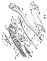
Figs. 3A-3E , theinstrument 2 is shown as aforceps 10 for use with open surgical procedures. Theforceps 10 is connected to thegenerator 20 via thecable 70 which includes aplug 300 configured for interfacing with an output port (not explicitly shown) of thegenerator 20. - The
forceps 10 includeselongated shaft portions proximal end distal end forceps 10 which is closer to the user, while the term "distal" will refer to the end which is further from the user. Theforceps 10 includes anend effector assembly 100 which attaches to the distal ends 16a and 16b ofshafts end effector assembly 100 includes pair of opposingjaw members pivot pin 65 and which are movable relative to one another to grasp tissue. - Preferably, each
shaft handle proximal end finger hole finger holes shafts jaw members jaw members jaw members - As best seen in
Fig. 3E ,shaft 12b is constructed from two components, namely, 12bl and 12b2, which matingly engage one another about thedistal end 16a ofshaft 12a to formshaft 12b. It is envisioned that the two component halves 12b1 and 12b2 may be ultrasonically-welded together at a plurality of different weld points or the component halves 12b1 and 12b2 may be mechanically engaged in any other known fashion, snap-fit, glued, screwed, etc. After component halves 12b and 12b2 are welded together to formshaft 12b,shaft 12a is secured aboutpivot 65 and positioned within a cut-out orrelief 21 defined within shaft portion 12b2 such thatshaft 12a is movable relative toshaft 12b. More particularly, when the user moves theshaft 12a relative toshaft 12b to close or open thejaw members shaft 12a moves withincutout 21 formed within portion 12b2. It is envisioned that configuring the twoshafts forceps 10 which is especially advantageous during surgeries in small cavities. - As best illustrated in
Fig. 3A-3B , one of the shafts, e.g., 12b, includes aproximal shaft connector 77 which is designed to connect theforceps 10 to thegenerator 20. Theproximal shaft connector 77 electromechanically engages thecable 70 such that the user may selectively apply electrosurgical energy as needed. Alternatively, thecable 70 may be feed directly intoshaft 12b (or 12a). Thecable 70 is coupled to theplug 300 which interfaces with thegenerator 20. - As explained in more detail below, the distal end of the
cable 70 connects to a handswitch 50 to permit the user to selectively apply electrosurgical energy as needed to seal tissue grasped betweenjaw members cable 70 houses leads 71a, 71b and 71c which upon activation of the handswitch 50 conduct the different electrical potentials from the electrosurgical generator to thejaw members 110 and 120 (SeeFig. 4 ). As can be appreciated, positioning theswitch 50 on theforceps 10 gives the user more visual and tactile control over the application of electrosurgical energy. These aspects are explained below with respect to the discussion of thehandswitch 50 and the electrical connections associated therewith. - The two opposing
jaw members end effector assembly 100 are pivotable aboutpin 65 from the open position to the closed position for grasping tissue therebetween. The pivot pin connects throughaperture 125 injaw member 120 andaperture 111 disposed throughjaw member 110.Pivot pin 65 typically consists of twocomponent halves shafts jaw members pivot pin 65 may be configured to be spring loaded such that the pivot snap-fits together at assembly to secure the twoshafts pivot pin 65. - The tissue grasping portions of the
jaw members pivot pin 65 to effect the grasping and sealing of tissue. As a result and unless otherwise noted,jaw member 110 and the operative features associated therewith are initially described herein in detail and the similar component features with respect tojaw member 120 will be briefly summarized thereafter. Moreover, many of the features of thejaw members U.S. Patent Publication Nos. 2003/0199869 ,2003/0014053 ,6,511,480 and6,277,117 andPCT Publication No. WO 2002/080797 . - As best shown in
Fig. 5 ,jaw member 110 includes an insulatedouter housing 116 which is dimensioned to mechanically engage an electricallyconductive sealing surface 112. The outerinsulative housing 116 extends along the entire length ofjaw member 110 to reduce alternate or stray current paths during sealing and/or incidental damage to tissue. The electricallyconductive surface 112 conducts electrosurgical energy of a first potential to the tissue upon activation of thehandswitch 50. Insulatedouter housing 116 is dimensioned to securely engage the electricallyconductive sealing surface 112. It is envisioned that this may be accomplished by stamping, by overmolding, by overmolding a stamped electrically conductive sealing plate and/or by overmolding a metal injection molded seal plate. Other methods of affixing theseal surface 112 to theouter housing 116 are described in detail in one or more of the above-identified references. Thejaw members - Likewise, as shown in
Fig. 3E ,jaw member 120 includes similar elements which include: anouter housing 126 which engages an electricallyconductive sealing surface 122 and an electricallyconducive sealing surface 122 which conducts electrosurgical energy of a second potential to the tissue upon activation of thehandswitch 50. - As best seen in
Figs. 5 and3E , thejaw members knife channel 115 disposed therebetween which is configured to allow reciprocation of acutting mechanism 80 therewithin. One example of a knife channel is disclosed inWO 02/080797 - It is envisioned that the
knife channel 115 may be tapered or some other configuration which facilitates or enhances cutting of the tissue during reciprocation of thecutting mechanism 80 in the distal direction. Moreover, theknife channel 115 may be formed with one or more safety features which prevent thecutting mechanism 80 from advancing through the tissue until thejaw members - The arrangement of
shaft 12b is slightly different fromshaft 12a. More particularly,shaft 12b is generally hollow to define a chamber therethrough which is dimensioned to house the handswitch 50 (and the electrical components associated therewith), theactuating mechanism 40 and thecutting mechanism 80. As best seen inFigs. 4 and3E , theactuating mechanism 40 includes a rack and pinion system having first and second gear tracks 42 and 86, respectively, and apinion 45 to advance thecutting mechanism 80. More particularly, theactuating mechanism 40 includes a trigger orfinger tab 43 which is operatively associated with afirst gear rack 42 such that movement of the trigger orfinger tab 43 moves thefirst rack 42 in a corresponding direction. Theactuating mechanism 40 mechanically cooperates with asecond gear rack 86 which is operatively associated with adrive rod 89 and which advances theentire cutting mechanism 80. Driverod 89 includes adistal end 81 which is configured to mechanically support thecutting blade 85 and which acts as part of a safety lockout mechanism as explained in more detail below. - Interdisposed between the first and second gear racks 42 and 86, respectively, is a
pinion gear 45 which mechanically meshes with 49 and 87 of gear racks 42 and 86 and converts proximal motion of thetrigger 43 into distal translation of thedrive rod 89 and vice versa. More particularly, when the user pulls thetrigger 43 in a proximal direction within a predisposedchannel 29 in theshaft 12b (See arrow "A" inFig. 3E ), thefirst rack 42 is translated proximally which, in turn, rotates thepinion gear 45 in a counter-clockwise direction. Rotation of thepinion gear 45 in a counter-clockwise direction forces thesecond rack 86 to translate thedrive rod 89 distally (See arrow "B" inFig. 3E ) which advances theblade 85 of thecutting mechanism 80 through tissue grasped betweenjaw members cutting mechanism 80, e.g., knife, blade, wire, etc., is advanced throughchannel 115 upon distal translation of thedrive rod 89. - A
spring 83 may be employed within chamber to bias thefirst rack 42 upon proximal movement thereof such that upon release of thetrigger 43, the force of thespring 83 automatically returns thefirst rack 42 to its distal most position withinchannel 29. Thespring 83 may be operatively connected to bias thesecond rack 86 to achieve the same purpose. - The proximal portion of
jaw member 120 also includes aguide slot 124 defined therethrough which allows aterminal connector 150 or so called "POGO" pin to ride therein upon movement of thejaw members terminal connector 150 is typically seated within arecess 113 of thejaw member 110. In addition, the proximal end includes anaperture 125 defined therethrough which houses thepivot pin 65. Theterminal connector 150 moves freely withinslot 124 upon rotation of thejaw members terminal connector 150 is seated withinaperture 151 withinjaw member 110 and rides withinslot 124 ofjaw member 120 to provide a "running" or "brush" contact to supply electrosurgical energy tojaw member 120 during the pivoting motion of theforceps 10. - The
jaw members conductive sealing surface 112. It is envisioned that thejaw members jaw members pivot 65. - In operation, the user simply utilizes the two opposing
handle members jaw members jaw member actuating mechanism 40 to advance thecutting blade 85 through the tissue to sever the tissue along the tissue seal to create a division between tissue halves. Figs. 3A-3D show aratchet 30 for selectively locking thejaw members first ratchet interface 31 a extends from theproximal end 14a ofshaft member 12a towards asecond ratchet interface 31b on theproximal end 14b ofshaft 12b in general vertical registration therewith such that the inner facing surfaces of each ratchet 31 a and 31 b abut one another upon closure of thejaw members ratchet interface ratchet interface ratchet interfaces ratchet interfaces shaft members jaw members - It is envisioned that the
ratchet 30 may include graduations or other visual markings which enable the user to easily and quickly ascertain and control the amount of closure force desired between the jaw members. It is envisioned that theshafts jaw members jaw members - The
proximal connector 77 may include a stop or protrusion 19 (SeeFigs. 3B-D ) which prevents the user from over pressurizing thejaw members handle forceps 10 are automatically configured to maintain the necessary closure pressure (about 3 kg/cm2 to about 16 kg/cm2) between the opposingjaw members Fig. 3E and4 show the electrical details relating to theswitch 50. More particularly and as mentioned above,cable 70 includes threeelectrical leads shaft 12b. The cable leads 71a, 71b and 71c are protected by two insulative layers, an outer protective sheath which surrounds all three leads 71 a, 71b and 71c and a secondary protective sheath which surrounds each individual cable lead, 71a, 71b and 71c, respectively. The two electrical potentials are isolated from one another by virtue of the insulative sheathing surrounding eachcable lead electrosurgical cable 70 is fed into the bottom ofshaft 12b and is held securely therein by one or more mechanical interfaces (not explicitly shown).- Lead 71c extends directly from
cable 70 and connects tojaw member 120 to conduct the second electrical potential thereto.Leads cable 70 and connect to acircuit board 52. The leads 71a-71b are secured to a series of corresponding contacts extending from thecircuit board 52 by a crimp-like connector (not explicitly shown) or other electromechanical connections which are commonly known in the art, e.g., IDC connections, soldering, etc. The leads 71a-71b are configured to transmit different electrical potentials or control signals to thecircuit board 52 which, in turn, regulates, monitors and controls the electrical energy to thejaw members Fig. 4 , theelectrical leads circuit board 52 such that when theswitch 50 is depressed, atrigger lead 72 carries the first electrical potential from thecircuit board 52 tojaw member 110. As mentioned above, the second electrical potential is carried by lead 71c directly from thegenerator 20 tojaw member 120 through theterminal connector 150 as described above. - As best shown in
Figs. 3A and3E , switch 50 includes an ergonomically dimensionedtoggle plate 53 which substantially conforms to the outer shape of housing (once assembled) ofinstrument 2. Thetoggle plate 53 is positioned in electro-mechanical communication with thecircuit board 52 along one side ofshaft 12b to facilitate activation ofswitch 50. As can be appreciated, the position of theswitch cap 53 enables the user to easily and selectively energize thejaw members switch cap 53 may be hermetically-sealed to avoid damage to thecircuit board 52 during wet operating conditions. In addition, it is contemplated that by positioning theswitch cap 53 at a side of theforceps 10 the overall sealing process is greatly simplified and ergonomically advantageous to the user, i.e., after closure, the user's finger is automatically poised for advancement of thecutting mechanism 80. - The
toggle plate 53 includes a pair ofprongs mechanical interfaces shaft 12b.Prongs shaft 12b during assembly.Toggle plate 53 also includes aswitch interface 55 which mates with aswitch button 56 which, in turn, connects to thecircuit board 52. When thetoggle plate 53 is depressed theswitch button 56 is pushed against thecircuit board 52 thereby actuating thehandswitch 50. - Several different types of
handswitches 50 are envisioned, for example, switch 50 is a regular push-button style switch but may be configured more like a toggle switch which permits the user to selectively activate theforceps 10 in a variety of different orientations, i.e., multi-oriented activation, which simplifies activation. One particular type of handswitch is disclosed inWO 02/080797 Fig. 6A shows alockout mechanism 200, which is not an embodiment of the invention as recited in the claims. Thelockout mechanism 200 is configured to prevent activation of theswitch 50. Thelockout mechanism 200 prevents theswitch 50 from being depressed to actuate theswitch button 56. Thelockout mechanism 200 includes alockout switch 210 having anactuating knob 212 extending transversally from alockout bar 214. Theactuating knob 212 is affixed to thelockout bar 214. Alternatively, thelockout bar 214 and theactuating knob 212 may be integrally formed. Theactuating knob 212 is dimensioned to protrude from the side ofshaft 12b when assembled and may include a variety of protrusions configured to facilitate gripping. Thelockout switch 210 may be formed from or coated with an insulative material (e.g., plastics, ceramics) to insulate thelockout switch 210 from any electrical current flowing through the instrument.- The
lockout switch 210 is slidably disposed within aguide channel 220 of theshaft 12b such that thelockout switch 210 is selectively moveable in the direction "C" therein. Thelockout switch 210 may be disposed facing any direction toward thehandswitch 50 and is configured to slide within theshaft 12b. As theactuating knob 212 is moved along the outside of theshaft 12b thelockout bar 214 moves correspondingly therein. In open configuration, thelockout switch 210 is moved away from theswitch 50 opposite the direction "C." This allows thetoggle plate 53, when depressed, to push theswitch button 56 into contact with thecircuit board 52 and thereby toggle application of electrosurgical energy. In locking configuration as shown inFig. 6B , thelockout switch 210 is slid in the direction "C" such that thelockout bar 214 is disposed at least partially between thetoggle plate 53 and thecircuit board 52. In locking configuration, when thetoggle plate 53 is depressed thetoggle plate 53 pushes against thelockout bar 214 and is prevented from actuating theswitch button 56. Thelockout bar 214 may be either in frictional contact with thetoggle plate 53 or a predetermined distance away therefrom such that the movement of thetoggle plate 53 is still limited. - The
lockout mechanism 200 may further include one or more tactile feedback elements, namely adetent 224 disposed within theguide channel 220 and agroove 222 configured to interface with thedetent 224. Thegroove 222 is disposed at thelockout bar 214 on the same longitudinal axis as thedetent 224 such that when thelockout switch 210 is moved in the direction "C" thegroove 222 interfaces with thedetent 224 providing tactile feedback to the user. Thegroove 222 and thedetent 224 are also dimensioned to provide frictional contact between thelockout switch 210 and theshaft 12b and prevent thelockout switch 210 from sliding out of locking configuration. Figs. 7A-B showdifferent lockout mechanisms 200, also not forming embodiments of the invention as recited in the claims. Thelockout switch 210 can be formed in a variety of shapes and sizes. As shown inFig. 7A , thelockout switch 210 may include thelockout bar 214 having an elongated shape.Fig. 7B shows thelockout switch 210 having a so-calledU-shaped lock 216 which slides into position below thetoggle plate 53. Thetoggle plate 53 may include a guide channel or a groove (not explicitly shown) disposed therein which are configured to interface with thelockout bar 214 and/or theU-shaped lock 216 when thelockout switch 210 is slid into locking configuration.- In addition to
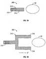
mechanical lockout mechanisms 200 illustrated inFigs. 6A-B and7A-B various electrical and electro-mechanical lockout mechanisms are contemplated.Fig. 8 shows anelectrical lockout mechanism 400 according to an embodiment of the invention as recited in the claims. Theplug 300 of theforceps 10 is plugged into thegenerator 20 and includes a plurality ofprongs 302, 304 and 306 connecting to the correspondingleads prong 306 provides a direct connection for sealingplate 122 to thegenerator 20 via the lead 71c. The prongs 302 and 304 are connected to thecircuit board 52 via theleads circuit board 52 is connected to the sealingplate 112 via thelead 72. During operation, theswitch 50 actuates theswitch button 56 which contacts thecircuit board 52. The circuit board includes anactivation switch 52a which is connected in series with the sealingplate 112 and thegenerator 20. Theswitch 52a is toggled via theswitch button 56. If theactivation switch 52a is closed and tissue is grasped between the sealingplates circuit board 52 also includes asafety switch 52b which is also in series with theactuation switch 52a. As long as either of the switches is open, the circuit is not complete and no electrosurgical energy is supplied to the tissue. - The
safety switch 52b may be toggled via a lockout push button disposed anywhere along theforceps 10. The lockout push button may be either manually or automatically actuated. In particular, the automatic actuation of the lockout push button may be accomplished by closure of theforceps 10. As shown inFig. 3C , thelockout push button 400 may be disposed on inner facing surface of thesecond ratchet interface 31b such that during closure of theforceps 10 when the first andsecond interfaces lockout push button 400 is activated (i.e., the schematically-illustratedsafety switch 52b is closed) allowing selective application of electrosurgical energy. - From the foregoing and with reference to the various figure drawings, those skilled in the art will appreciate that certain modifications can also be made to the present disclosure without departing from the scope of the same. For example and as mentioned above, it is contemplated that any of the lockout mechanisms disclosed herein may be employed in an endoscopic forceps such as the
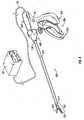
endoscopic forceps 500 disclosed inFig. 9 . Fig. 9 shows theforceps 500 which is configured to support anend effector assembly 502 at a distal end thereof. More particularly,forceps 500 generally includes ahousing 504, ahandle assembly 506, a rotatingassembly 508, and a trigger assembly that mutually cooperate with theend effector assembly 502 to grasp, seal and, if required, divide tissue.- The
forceps 500 also includes ashaft 512 that has adistal end 514 which mechanically engages theend effector assembly 502 and aproximal end 516 which mechanically engages thehousing 504 proximate therotating assembly 508. In the drawings and in the description which follows, the term "proximal", refers to the end of theforceps 500 which is closer to the user, while the term "distal" refers to the end of the forceps which is further from the user. Handle assembly 506 includes a fixedhandle 520 and amovable handle 522. Handle 522 moves relative to the fixedhandle 520 to actuate theend effector assembly 502 and enables a user to grasp and manipulate tissue.- The
end effector assembly 502 includes a pair of opposingjaw members jaw members handle 522 from an open position to a closed position. In open position the sealing plates are disposed in spaced relation relative to one another. In a clamping or closed position the sealing plates cooperate to grasp tissue and apply electrosurgical energy thereto once the user activates the handswitch 50 which is disposed on thehousing 504. - The
jaw members housing 504. The drive assembly cooperates with themovable handle 522 to impart movement of thejaw members U.S. Publication No. 2004/0186245 entitled "VESSEL SEALER AND DIVIDER AND METHOD MANUFACTURING SAME" and commonly ownedU.S. Publication No. 2004/0254573,926 - In addition, the
handle assembly 506 of this particular disclosure may include a four-bar mechanical linkage, which provides a unique mechanical advantage when sealing tissue between thejaw members jaw members Movable handle 522 ofhandle assembly 506 is ultimately connected to a drive rod (not explicitly shown) housed within theshaft 512 which, together, mechanically cooperate to impart movement of thejaw members jaw jaw members - Further details relating to one particular open forceps are disclosed in commonly-owned
U.S. Publication No. 2004/0254573 filed June 13, 2003 entitled "VESSEL SEALER AND DIVIDER FOR USE WITH SMALL TROCARS AND CANNULAS". - From the foregoing and with reference to the various figure drawings, those skilled in the art will appreciate that certain modifications can also be made to the present disclosure without departing from the scope of the same. For example, although the electrical connections are preferably incorporated within one
shaft 12b and theforceps 10 is intended for right-handed use, it is contemplated the electrical connections may be incorporated within theother shaft 12a depending upon a particular purpose and/or to facilitate manipulation by a left-handed user. Alternatively, theforceps 10 may operated in an upside down orientation for left-handed users without compromising or restricting any operating characteristics of theforceps 10. - It is also contemplated that the forceps 10 (and/or the electrosurgical generator used in connection with the forceps 10) may include a sensor or feedback mechanism (not explicitly shown) which automatically selects the appropriate amount of electrosurgical energy to effectively seal the particularly-sized tissue grasped between the
jaw members jaw members U.S. Patent Publication No. 2004/0015163 discloses several different types of sensory feedback mechanisms and algorithms which may be utilized for this purpose. - It is envisioned that a safety switch or circuit (not shown) may be employed such that the
switch 50 cannot fire unless thejaw members jaw members U.S. Patent Publication No. 2004/0015163 . - It is also envisioned that the mechanical and electrical lockout mechanisms disclosed herein may be included in a single instrument providing redundant lockout systems.
- While several embodiments of the disclosure have been shown in the drawings and/or discussed herein, it is not intended that the disclosure be limited thereto, as it is intended that the disclosure be as broad in scope as the art will allow and that the specification be read likewise. Therefore, the above description should not be construed as limiting, but merely as exemplifications of particular embodiments. Those skilled in the art will envision other modifications within the scope of the claims appended hereto.
Claims (10)
- An electrosurgical forceps (10) for sealing tissue, comprising:at least one handle (15, 17) having at least one shaft member (12a, 12b) attached thereto, said at least one shaft member having an end effector (100) attached at a distal end thereof, said end effector including a pair of jaw members (110, 120) being movable from a first position in spaced relation relative to one another to at least one subsequent position wherein the jaw members cooperate to grasp tissue therebetween, each of the jaw members including an electrically conductive sealing plate for communicating electrosurgical energy through tissue held therebetween to effect a tissue seal, the electrically conductive sealing plates adapted to connect to an electrosurgical generator;wherein the electrosurgical forceps is an open electrosurgical forceps having a pair of first and second handles (15, 17), each of said handles including shaft members (12a, 12b) having a jaw member (110, 120) disposed at a distal end thereof and a ratchet interface (31a, 31 b) at a proximal end thereof, said jaw members being selectively movable via operation of said handles from a first position in spaced relation relative to one another to at least one subsequent position wherein the jaw members cooperate to grasp tissue therebetween;a handswitch (50) operatively coupled to at least one of said at least one handle and said at least one shaft member, said handswitch adapted to connect to the electrosurgical generator, said handswitch being selectively actuatable to initiate electrosurgical activation of the forceps, anda lockout switch (400);characterised by:the lockout switch (400) being operatively coupled to at least one of the ratchet interfaces (31a, 31b), the lockout switch having a first configuration wherein said ratchet interfaces are disposed in spaced, non-operative engagement with one another which prevents actuation of said handswitch and a second configuration wherein said ratchet interfaces are operatively engaged with one another which allows actuation of said handswitch and activation of said forceps.
- An electrosurgical forceps according to claim 1, wherein the handswitch is a toggle switch including a toggle plate (53), a circuit board (52) and a switch button (56) disposed therebetween.
- The electrosurgical forceps according to claim 2, wherein the handswitch is configured so that when the toggle plate is depressed, the switch button is pushed against an activation switch (52a) of the circuit board (52), wherein the circuit board further includes a safety switch (52b) which is configured to be toggled by the lockout switch; configured so that as long as either of the safety switch or the actuation switch is open, a circuit connecting the activation switch and the safety switch in series with the sealing plate and an electrosurgical generator is incomplete.
- An electrosurgical forceps according to any one of the preceding claims, wherein the lockout switch is configured in electrical communication with said handswitch such that both said lockout switch and said handswitch must be electrically closed to allow activation of said forceps.
- An electrosurgical forceps according to any one of the preceding claims, wherein the ratchet interfaces are in general vertical registration with one another such inner facing surfaces thereof abut one another upon closure of the jaw members about tissue to lock the jaw members relative to one another in at least one position.
- An electrosurgical forceps according to any one of the preceding claims, wherein each ratchet interface includes at least one step-like flange or a plurality of step-like flanges which project from an inner facing surface of each ratchet interface such that the ratchet interfaces interlock in at least one position.
- An electrosurgical forceps according to any one of the preceding claims, comprising a plurality of positions associated with the cooperating ratchet interfaces, wherein each position holds a specific strain energy in the shaft members which, in turn, transmits a specific closing force to the jaw members.
- An electrosurgical forceps according to any one of the preceding claims, wherein the lockout switch is disposed on the inner facing surface of one of the ratchet interfaces such that during closure of the forceps when the first and second interfaces respectively abut one another, the lockout switch is activated allowing activation of the handswitch and activation of said forceps.
- An electrosurgical forceps according to any one of the preceding claims, wherein the ratchet interfaces are for selectively locking the jaw members relative to one another in at least one position.
- An electrosurgical forceps according to any one of the preceding claims, wherein the lockout switch is made from an electrically insulative material.
Priority Applications (1)
| Application Number | Priority Date | Filing Date | Title |
|---|---|---|---|
| EP09015215AEP2168517A1 (en) | 2006-08-04 | 2007-08-02 | Hanheld electrosurgical instruments having disable handswitches |
Applications Claiming Priority (1)
| Application Number | Priority Date | Filing Date | Title |
|---|---|---|---|
| US11/499,590US20080033428A1 (en) | 2006-08-04 | 2006-08-04 | System and method for disabling handswitching on an electrosurgical instrument |
Related Child Applications (1)
| Application Number | Title | Priority Date | Filing Date |
|---|---|---|---|
| EP09015215.8Division-Into | 2009-12-08 |
Publications (2)
| Publication Number | Publication Date |
|---|---|
| EP1889583A1 EP1889583A1 (en) | 2008-02-20 |
| EP1889583B1true EP1889583B1 (en) | 2011-04-13 |
Family
ID=38728914
Family Applications (2)
| Application Number | Title | Priority Date | Filing Date |
|---|---|---|---|
| EP07015191ANot-in-forceEP1889583B1 (en) | 2006-08-04 | 2007-08-02 | Handheld electrosurgical instruments having disable handswitches |
| EP09015215AWithdrawnEP2168517A1 (en) | 2006-08-04 | 2007-08-02 | Hanheld electrosurgical instruments having disable handswitches |
Family Applications After (1)
| Application Number | Title | Priority Date | Filing Date |
|---|---|---|---|
| EP09015215AWithdrawnEP2168517A1 (en) | 2006-08-04 | 2007-08-02 | Hanheld electrosurgical instruments having disable handswitches |
Country Status (7)
| Country | Link |
|---|---|
| US (1) | US20080033428A1 (en) |
| EP (2) | EP1889583B1 (en) |
| JP (2) | JP2008036437A (en) |
| AU (1) | AU2007203637B2 (en) |
| CA (1) | CA2595817A1 (en) |
| DE (1) | DE602007013842D1 (en) |
| ES (1) | ES2364285T3 (en) |
Cited By (18)
| Publication number | Priority date | Publication date | Assignee | Title |
|---|---|---|---|---|
| US10092359B2 (en) | 2010-10-11 | 2018-10-09 | Ecole Polytechnique Federale De Lausanne | Mechanical manipulator for surgical instruments |
| US10265129B2 (en) | 2014-02-03 | 2019-04-23 | Distalmotion Sa | Mechanical teleoperated device comprising an interchangeable distal instrument |
| US10325072B2 (en) | 2011-07-27 | 2019-06-18 | Ecole Polytechnique Federale De Lausanne (Epfl) | Mechanical teleoperated device for remote manipulation |
| US10357320B2 (en) | 2014-08-27 | 2019-07-23 | Distalmotion Sa | Surgical system for microsurgical techniques |
| US10363055B2 (en) | 2015-04-09 | 2019-07-30 | Distalmotion Sa | Articulated hand-held instrument |
| US10413374B2 (en) | 2018-02-07 | 2019-09-17 | Distalmotion Sa | Surgical robot systems comprising robotic telemanipulators and integrated laparoscopy |
| US10548680B2 (en) | 2014-12-19 | 2020-02-04 | Distalmotion Sa | Articulated handle for mechanical telemanipulator |
| US10568709B2 (en) | 2015-04-09 | 2020-02-25 | Distalmotion Sa | Mechanical teleoperated device for remote manipulation |
| US10646294B2 (en) | 2014-12-19 | 2020-05-12 | Distalmotion Sa | Reusable surgical instrument for minimally invasive procedures |
| US10786272B2 (en) | 2015-08-28 | 2020-09-29 | Distalmotion Sa | Surgical instrument with increased actuation force |
| US10864052B2 (en) | 2014-12-19 | 2020-12-15 | Distalmotion Sa | Surgical instrument with articulated end-effector |
| US10864049B2 (en) | 2014-12-19 | 2020-12-15 | Distalmotion Sa | Docking system for mechanical telemanipulator |
| US11039820B2 (en) | 2014-12-19 | 2021-06-22 | Distalmotion Sa | Sterile interface for articulated surgical instruments |
| US11058503B2 (en) | 2017-05-11 | 2021-07-13 | Distalmotion Sa | Translational instrument interface for surgical robot and surgical robot systems comprising the same |
| US11844585B1 (en) | 2023-02-10 | 2023-12-19 | Distalmotion Sa | Surgical robotics systems and devices having a sterile restart, and methods thereof |
| US12114945B2 (en) | 2021-09-13 | 2024-10-15 | Distalmotion Sa | Instruments for surgical robotic system and interfaces for the same |
| US12376927B2 (en) | 2018-02-07 | 2025-08-05 | Distalmotion Sa | Surgical robot systems comprising robotic telemanipulators and integrated laparoscopy |
| US12402960B2 (en) | 2010-10-11 | 2025-09-02 | Ecole Polytechnique Federale De Lausanne (Epfl) | Mechanical manipulator for surgical instruments |
Families Citing this family (159)
| Publication number | Priority date | Publication date | Assignee | Title |
|---|---|---|---|---|
| US6267761B1 (en)* | 1997-09-09 | 2001-07-31 | Sherwood Services Ag | Apparatus and method for sealing and cutting tissue |
| US6726686B2 (en) | 1997-11-12 | 2004-04-27 | Sherwood Services Ag | Bipolar electrosurgical instrument for sealing vessels |
| US7435249B2 (en)* | 1997-11-12 | 2008-10-14 | Covidien Ag | Electrosurgical instruments which reduces collateral damage to adjacent tissue |
| US6228083B1 (en)* | 1997-11-14 | 2001-05-08 | Sherwood Services Ag | Laparoscopic bipolar electrosurgical instrument |
| US7582087B2 (en)* | 1998-10-23 | 2009-09-01 | Covidien Ag | Vessel sealing instrument |
| US20040249374A1 (en) | 1998-10-23 | 2004-12-09 | Tetzlaff Philip M. | Vessel sealing instrument |
| US7364577B2 (en) | 2002-02-11 | 2008-04-29 | Sherwood Services Ag | Vessel sealing system |
| US7267677B2 (en) | 1998-10-23 | 2007-09-11 | Sherwood Services Ag | Vessel sealing instrument |
| US7118570B2 (en) | 2001-04-06 | 2006-10-10 | Sherwood Services Ag | Vessel sealing forceps with disposable electrodes |
| US7887535B2 (en)* | 1999-10-18 | 2011-02-15 | Covidien Ag | Vessel sealing wave jaw |
| US20030109875A1 (en) | 1999-10-22 | 2003-06-12 | Tetzlaff Philip M. | Open vessel sealing forceps with disposable electrodes |
| US20030229344A1 (en)* | 2002-01-22 | 2003-12-11 | Dycus Sean T. | Vessel sealer and divider and method of manufacturing same |
| ES2262639T3 (en) | 2001-04-06 | 2006-12-01 | Sherwood Services Ag | SHUTTER AND DIVIDER OF GLASSES WITH BUMPER MEMBERS N OCONDUCTIVES. |
| EP1527747B1 (en) | 2001-04-06 | 2015-09-30 | Covidien AG | Electrosurgical instrument which reduces collateral damage to adjacent tissue |
| US7101371B2 (en) | 2001-04-06 | 2006-09-05 | Dycus Sean T | Vessel sealer and divider |
| US10849681B2 (en) | 2001-04-06 | 2020-12-01 | Covidien Ag | Vessel sealer and divider |
| AU2001249937B2 (en)* | 2001-04-06 | 2006-02-09 | Covidien Ag | Vessel sealing instrument |
| AU2002250551B2 (en)* | 2001-04-06 | 2006-02-02 | Covidien Ag | Molded insulating hinge for bipolar instruments |
| US20040115296A1 (en)* | 2002-04-05 | 2004-06-17 | Duffin Terry M. | Retractable overmolded insert retention apparatus |
| EP1683496B1 (en)* | 2002-06-06 | 2008-12-10 | Covidien AG | Laparoscopic bipolar electrosurgical instrument |
| US7270664B2 (en)* | 2002-10-04 | 2007-09-18 | Sherwood Services Ag | Vessel sealing instrument with electrical cutting mechanism |
| US7931649B2 (en) | 2002-10-04 | 2011-04-26 | Tyco Healthcare Group Lp | Vessel sealing instrument with electrical cutting mechanism |
| US7276068B2 (en) | 2002-10-04 | 2007-10-02 | Sherwood Services Ag | Vessel sealing instrument with electrical cutting mechanism |
| US7799026B2 (en) | 2002-11-14 | 2010-09-21 | Covidien Ag | Compressible jaw configuration with bipolar RF output electrodes for soft tissue fusion |
| US7033354B2 (en)* | 2002-12-10 | 2006-04-25 | Sherwood Services Ag | Electrosurgical electrode having a non-conductive porous ceramic coating |
| US20060064086A1 (en)* | 2003-03-13 | 2006-03-23 | Darren Odom | Bipolar forceps with multiple electrode array end effector assembly |
| EP1601298B1 (en)* | 2003-03-13 | 2016-09-07 | Covidien AG | Bipolar concentric electrode assembly for soft tissue fusion |
| CA2523675C (en) | 2003-05-01 | 2016-04-26 | Sherwood Services Ag | Electrosurgical instrument which reduces thermal damage to adjacent tissue |
| US8128624B2 (en)* | 2003-05-01 | 2012-03-06 | Covidien Ag | Electrosurgical instrument that directs energy delivery and protects adjacent tissue |
| US7160299B2 (en) | 2003-05-01 | 2007-01-09 | Sherwood Services Ag | Method of fusing biomaterials with radiofrequency energy |
| JP5137230B2 (en) | 2003-05-15 | 2013-02-06 | コヴィディエン・アクチェンゲゼルシャフト | Tissue sealer with non-conductive variable stop member and method for sealing tissue |
| US7597693B2 (en)* | 2003-06-13 | 2009-10-06 | Covidien Ag | Vessel sealer and divider for use with small trocars and cannulas |
| US7150749B2 (en) | 2003-06-13 | 2006-12-19 | Sherwood Services Ag | Vessel sealer and divider having elongated knife stroke and safety cutting mechanism |
| US7857812B2 (en) | 2003-06-13 | 2010-12-28 | Covidien Ag | Vessel sealer and divider having elongated knife stroke and safety for cutting mechanism |
| US7156846B2 (en) | 2003-06-13 | 2007-01-02 | Sherwood Services Ag | Vessel sealer and divider for use with small trocars and cannulas |
| USD956973S1 (en) | 2003-06-13 | 2022-07-05 | Covidien Ag | Movable handle for endoscopic vessel sealer and divider |
| US9848938B2 (en) | 2003-11-13 | 2017-12-26 | Covidien Ag | Compressible jaw configuration with bipolar RF output electrodes for soft tissue fusion |
| US7367976B2 (en) | 2003-11-17 | 2008-05-06 | Sherwood Services Ag | Bipolar forceps having monopolar extension |
| US7232440B2 (en)* | 2003-11-17 | 2007-06-19 | Sherwood Services Ag | Bipolar forceps having monopolar extension |
| US7811283B2 (en)* | 2003-11-19 | 2010-10-12 | Covidien Ag | Open vessel sealing instrument with hourglass cutting mechanism and over-ratchet safety |
| US7131970B2 (en) | 2003-11-19 | 2006-11-07 | Sherwood Services Ag | Open vessel sealing instrument with cutting mechanism |
| US7500975B2 (en) | 2003-11-19 | 2009-03-10 | Covidien Ag | Spring loaded reciprocating tissue cutting mechanism in a forceps-style electrosurgical instrument |
| US7442193B2 (en) | 2003-11-20 | 2008-10-28 | Covidien Ag | Electrically conductive/insulative over-shoe for tissue fusion |
| US7780662B2 (en) | 2004-03-02 | 2010-08-24 | Covidien Ag | Vessel sealing system using capacitive RF dielectric heating |
| US7195631B2 (en)* | 2004-09-09 | 2007-03-27 | Sherwood Services Ag | Forceps with spring loaded end effector assembly |
| US7540872B2 (en) | 2004-09-21 | 2009-06-02 | Covidien Ag | Articulating bipolar electrosurgical instrument |
| US20060190035A1 (en)* | 2004-10-08 | 2006-08-24 | Sherwood Services Ag | Latching mechanism for forceps |
| US20060079933A1 (en)* | 2004-10-08 | 2006-04-13 | Dylan Hushka | Latching mechanism for forceps |
| US7955332B2 (en) | 2004-10-08 | 2011-06-07 | Covidien Ag | Mechanism for dividing tissue in a hemostat-style instrument |
| US7686827B2 (en) | 2004-10-21 | 2010-03-30 | Covidien Ag | Magnetic closure mechanism for hemostat |
| US7686804B2 (en) | 2005-01-14 | 2010-03-30 | Covidien Ag | Vessel sealer and divider with rotating sealer and cutter |
| US7909823B2 (en) | 2005-01-14 | 2011-03-22 | Covidien Ag | Open vessel sealing instrument |
| US7491202B2 (en) | 2005-03-31 | 2009-02-17 | Covidien Ag | Electrosurgical forceps with slow closure sealing plates and method of sealing tissue |
| US7837685B2 (en)* | 2005-07-13 | 2010-11-23 | Covidien Ag | Switch mechanisms for safe activation of energy on an electrosurgical instrument |
| US7628791B2 (en)* | 2005-08-19 | 2009-12-08 | Covidien Ag | Single action tissue sealer |
| US7922953B2 (en) | 2005-09-30 | 2011-04-12 | Covidien Ag | Method for manufacturing an end effector assembly |
| US7879035B2 (en) | 2005-09-30 | 2011-02-01 | Covidien Ag | Insulating boot for electrosurgical forceps |
| US7789878B2 (en) | 2005-09-30 | 2010-09-07 | Covidien Ag | In-line vessel sealer and divider |
| US7722607B2 (en) | 2005-09-30 | 2010-05-25 | Covidien Ag | In-line vessel sealer and divider |
| ES2381560T3 (en) | 2005-09-30 | 2012-05-29 | Covidien Ag | Insulating sleeve for electrosurgical forceps |
| CA2561034C (en) | 2005-09-30 | 2014-12-09 | Sherwood Services Ag | Flexible endoscopic catheter with an end effector for coagulating and transfecting tissue |
| US7594916B2 (en)* | 2005-11-22 | 2009-09-29 | Covidien Ag | Electrosurgical forceps with energy based tissue division |
| US20070118115A1 (en)* | 2005-11-22 | 2007-05-24 | Sherwood Services Ag | Bipolar electrosurgical sealing instrument having an improved tissue gripping device |
| US7766910B2 (en)* | 2006-01-24 | 2010-08-03 | Tyco Healthcare Group Lp | Vessel sealer and divider for large tissue structures |
| US8734443B2 (en) | 2006-01-24 | 2014-05-27 | Covidien Lp | Vessel sealer and divider for large tissue structures |
| US8241282B2 (en) | 2006-01-24 | 2012-08-14 | Tyco Healthcare Group Lp | Vessel sealing cutting assemblies |
| US8882766B2 (en)* | 2006-01-24 | 2014-11-11 | Covidien Ag | Method and system for controlling delivery of energy to divide tissue |
| US8298232B2 (en) | 2006-01-24 | 2012-10-30 | Tyco Healthcare Group Lp | Endoscopic vessel sealer and divider for large tissue structures |
| US7641653B2 (en)* | 2006-05-04 | 2010-01-05 | Covidien Ag | Open vessel sealing forceps disposable handswitch |
| US20070260238A1 (en)* | 2006-05-05 | 2007-11-08 | Sherwood Services Ag | Combined energy level button |
| US7846158B2 (en) | 2006-05-05 | 2010-12-07 | Covidien Ag | Apparatus and method for electrode thermosurgery |
| US20070265616A1 (en)* | 2006-05-10 | 2007-11-15 | Sherwood Services Ag | Vessel sealing instrument with optimized power density |
| US7776037B2 (en) | 2006-07-07 | 2010-08-17 | Covidien Ag | System and method for controlling electrode gap during tissue sealing |
| US20080015575A1 (en)* | 2006-07-14 | 2008-01-17 | Sherwood Services Ag | Vessel sealing instrument with pre-heated electrodes |
| US7744615B2 (en)* | 2006-07-18 | 2010-06-29 | Covidien Ag | Apparatus and method for transecting tissue on a bipolar vessel sealing instrument |
| US7731717B2 (en)* | 2006-08-08 | 2010-06-08 | Covidien Ag | System and method for controlling RF output during tissue sealing |
| US8597297B2 (en) | 2006-08-29 | 2013-12-03 | Covidien Ag | Vessel sealing instrument with multiple electrode configurations |
| US8070746B2 (en) | 2006-10-03 | 2011-12-06 | Tyco Healthcare Group Lp | Radiofrequency fusion of cardiac tissue |
| US7951149B2 (en)* | 2006-10-17 | 2011-05-31 | Tyco Healthcare Group Lp | Ablative material for use with tissue treatment device |
| US7785060B2 (en)* | 2006-10-27 | 2010-08-31 | Applied Materials, Inc. | Multi-directional mechanical scanning in an ion implanter |
| USD649249S1 (en) | 2007-02-15 | 2011-11-22 | Tyco Healthcare Group Lp | End effectors of an elongated dissecting and dividing instrument |
| US8267935B2 (en)* | 2007-04-04 | 2012-09-18 | Tyco Healthcare Group Lp | Electrosurgical instrument reducing current densities at an insulator conductor junction |
| US7877852B2 (en) | 2007-09-20 | 2011-02-01 | Tyco Healthcare Group Lp | Method of manufacturing an end effector assembly for sealing tissue |
| US7877853B2 (en) | 2007-09-20 | 2011-02-01 | Tyco Healthcare Group Lp | Method of manufacturing end effector assembly for sealing tissue |
| US8235992B2 (en) | 2007-09-28 | 2012-08-07 | Tyco Healthcare Group Lp | Insulating boot with mechanical reinforcement for electrosurgical forceps |
| US8235993B2 (en) | 2007-09-28 | 2012-08-07 | Tyco Healthcare Group Lp | Insulating boot for electrosurgical forceps with exohinged structure |
| US8267936B2 (en)* | 2007-09-28 | 2012-09-18 | Tyco Healthcare Group Lp | Insulating mechanically-interfaced adhesive for electrosurgical forceps |
| US8236025B2 (en) | 2007-09-28 | 2012-08-07 | Tyco Healthcare Group Lp | Silicone insulated electrosurgical forceps |
| AU2008221509B2 (en) | 2007-09-28 | 2013-10-10 | Covidien Lp | Dual durometer insulating boot for electrosurgical forceps |
| US8251996B2 (en) | 2007-09-28 | 2012-08-28 | Tyco Healthcare Group Lp | Insulating sheath for electrosurgical forceps |
| US8221416B2 (en) | 2007-09-28 | 2012-07-17 | Tyco Healthcare Group Lp | Insulating boot for electrosurgical forceps with thermoplastic clevis |
| US9023043B2 (en) | 2007-09-28 | 2015-05-05 | Covidien Lp | Insulating mechanically-interfaced boot and jaws for electrosurgical forceps |
| US8764748B2 (en) | 2008-02-06 | 2014-07-01 | Covidien Lp | End effector assembly for electrosurgical device and method for making the same |
| US8623276B2 (en) | 2008-02-15 | 2014-01-07 | Covidien Lp | Method and system for sterilizing an electrosurgical instrument |
| US8357158B2 (en) | 2008-04-22 | 2013-01-22 | Covidien Lp | Jaw closure detection system |
| US8469956B2 (en) | 2008-07-21 | 2013-06-25 | Covidien Lp | Variable resistor jaw |
| US8968355B2 (en) | 2008-08-04 | 2015-03-03 | Covidien Lp | Articulating surgical device |
| US8801752B2 (en)* | 2008-08-04 | 2014-08-12 | Covidien Lp | Articulating surgical device |
| US8257387B2 (en) | 2008-08-15 | 2012-09-04 | Tyco Healthcare Group Lp | Method of transferring pressure in an articulating surgical instrument |
| US8162973B2 (en) | 2008-08-15 | 2012-04-24 | Tyco Healthcare Group Lp | Method of transferring pressure in an articulating surgical instrument |
| US9603652B2 (en) | 2008-08-21 | 2017-03-28 | Covidien Lp | Electrosurgical instrument including a sensor |
| US8795274B2 (en) | 2008-08-28 | 2014-08-05 | Covidien Lp | Tissue fusion jaw angle improvement |
| US8317787B2 (en) | 2008-08-28 | 2012-11-27 | Covidien Lp | Tissue fusion jaw angle improvement |
| US8784417B2 (en) | 2008-08-28 | 2014-07-22 | Covidien Lp | Tissue fusion jaw angle improvement |
| US8303582B2 (en) | 2008-09-15 | 2012-11-06 | Tyco Healthcare Group Lp | Electrosurgical instrument having a coated electrode utilizing an atomic layer deposition technique |
| US8968314B2 (en) | 2008-09-25 | 2015-03-03 | Covidien Lp | Apparatus, system and method for performing an electrosurgical procedure |
| US9375254B2 (en) | 2008-09-25 | 2016-06-28 | Covidien Lp | Seal and separate algorithm |
| US8535312B2 (en) | 2008-09-25 | 2013-09-17 | Covidien Lp | Apparatus, system and method for performing an electrosurgical procedure |
| US8142473B2 (en) | 2008-10-03 | 2012-03-27 | Tyco Healthcare Group Lp | Method of transferring rotational motion in an articulating surgical instrument |
| US8469957B2 (en) | 2008-10-07 | 2013-06-25 | Covidien Lp | Apparatus, system, and method for performing an electrosurgical procedure |
| US8636761B2 (en) | 2008-10-09 | 2014-01-28 | Covidien Lp | Apparatus, system, and method for performing an endoscopic electrosurgical procedure |
| US8016827B2 (en) | 2008-10-09 | 2011-09-13 | Tyco Healthcare Group Lp | Apparatus, system, and method for performing an electrosurgical procedure |
| US8486107B2 (en) | 2008-10-20 | 2013-07-16 | Covidien Lp | Method of sealing tissue using radiofrequency energy |
| US8197479B2 (en) | 2008-12-10 | 2012-06-12 | Tyco Healthcare Group Lp | Vessel sealer and divider |
| US8114122B2 (en) | 2009-01-13 | 2012-02-14 | Tyco Healthcare Group Lp | Apparatus, system, and method for performing an electrosurgical procedure |
| US8282634B2 (en)* | 2009-01-14 | 2012-10-09 | Tyco Healthcare Group Lp | Apparatus, system, and method for performing an electrosurgical procedure |
| US20100249769A1 (en)* | 2009-03-24 | 2010-09-30 | Tyco Healthcare Group Lp | Apparatus for Tissue Sealing |
| US8444642B2 (en)* | 2009-04-03 | 2013-05-21 | Device Evolutions, Llc | Laparoscopic nephrectomy device |
| US8187273B2 (en) | 2009-05-07 | 2012-05-29 | Tyco Healthcare Group Lp | Apparatus, system, and method for performing an electrosurgical procedure |
| US8246618B2 (en) | 2009-07-08 | 2012-08-21 | Tyco Healthcare Group Lp | Electrosurgical jaws with offset knife |
| US8430876B2 (en) | 2009-08-27 | 2013-04-30 | Tyco Healthcare Group Lp | Vessel sealer and divider with knife lockout |
| US8133254B2 (en) | 2009-09-18 | 2012-03-13 | Tyco Healthcare Group Lp | In vivo attachable and detachable end effector assembly and laparoscopic surgical instrument and methods therefor |
| US8112871B2 (en) | 2009-09-28 | 2012-02-14 | Tyco Healthcare Group Lp | Method for manufacturing electrosurgical seal plates |
| US9024237B2 (en)* | 2009-09-29 | 2015-05-05 | Covidien Lp | Material fusing apparatus, system and method of use |
| US8808288B2 (en) | 2010-03-08 | 2014-08-19 | Covidien Lp | Surgical forceps including belt blade reverser mechanism |
| US9655672B2 (en)* | 2010-10-04 | 2017-05-23 | Covidien Lp | Vessel sealing instrument |
| US9345534B2 (en) | 2010-10-04 | 2016-05-24 | Covidien Lp | Vessel sealing instrument |
| US9113940B2 (en) | 2011-01-14 | 2015-08-25 | Covidien Lp | Trigger lockout and kickback mechanism for surgical instruments |
| US20120239034A1 (en)* | 2011-03-17 | 2012-09-20 | Tyco Healthcare Group Lp | Method of Manufacturing Tissue Seal Plates |
| USD680220S1 (en) | 2012-01-12 | 2013-04-16 | Coviden IP | Slider handle for laparoscopic device |
| US8968360B2 (en) | 2012-01-25 | 2015-03-03 | Covidien Lp | Surgical instrument with resilient driving member and related methods of use |
| US9039731B2 (en) | 2012-05-08 | 2015-05-26 | Covidien Lp | Surgical forceps including blade safety mechanism |
| US8679140B2 (en) | 2012-05-30 | 2014-03-25 | Covidien Lp | Surgical clamping device with ratcheting grip lock |
| JP6141506B2 (en) | 2013-03-15 | 2017-06-07 | ジャイラス エーシーエムアイ インク | Combined electrosurgical device |
| CN105142556B (en) | 2013-03-15 | 2019-01-08 | 捷锐士阿希迈公司(以奥林巴斯美国外科技术名义) | Bias surgical clamp |
| CN105380711B (en) | 2013-03-15 | 2018-01-02 | 捷锐士阿希迈公司(以奥林巴斯美国外科技术名义) | Combine electrosurgery device |
| WO2014143472A1 (en) | 2013-03-15 | 2014-09-18 | GYRUS ACMI, INC. (d/b/a OLYMPUS SURGICAL TECHNOLOGIES AMERICA) | Electrosurgical instrument |
| JP6153654B2 (en) | 2013-03-15 | 2017-06-28 | ジャイラス エーシーエムアイ インク | Combined electrosurgical device |
| US9622810B2 (en)* | 2013-05-10 | 2017-04-18 | Covidien Lp | Surgical forceps |
| CN105451670B (en) | 2013-08-07 | 2018-09-04 | 柯惠有限合伙公司 | Surgery forceps |
| DE102013110172A1 (en) | 2013-09-16 | 2015-03-19 | Aesculap Ag | Method and device for controlling an electrosurgical HF device and HF device |
| DE102013110595A1 (en)* | 2013-09-25 | 2015-04-09 | Aesculap Ag | HF surgical instrument |
| US10258404B2 (en) | 2014-04-24 | 2019-04-16 | Gyrus, ACMI, Inc. | Partially covered jaw electrodes |
| WO2016028835A1 (en) | 2014-08-20 | 2016-02-25 | GYRUS ACMI, INC. (d/b/a OLYMPUS SURGICAL TECHNOLOGIES AMERICA) | Surgical forceps and latching system |
| US10231777B2 (en) | 2014-08-26 | 2019-03-19 | Covidien Lp | Methods of manufacturing jaw members of an end-effector assembly for a surgical instrument |
| EP3581133A1 (en) | 2015-03-23 | 2019-12-18 | Gyrus ACMI, Inc. (D.B.A. Olympus Surgical Technologies America) | Medical forceps with vessel transection capability |
| US9987078B2 (en) | 2015-07-22 | 2018-06-05 | Covidien Lp | Surgical forceps |
| US10987159B2 (en) | 2015-08-26 | 2021-04-27 | Covidien Lp | Electrosurgical end effector assemblies and electrosurgical forceps configured to reduce thermal spread |
| US10213250B2 (en) | 2015-11-05 | 2019-02-26 | Covidien Lp | Deployment and safety mechanisms for surgical instruments |
| US10856933B2 (en) | 2016-08-02 | 2020-12-08 | Covidien Lp | Surgical instrument housing incorporating a channel and methods of manufacturing the same |
| US10918407B2 (en) | 2016-11-08 | 2021-02-16 | Covidien Lp | Surgical instrument for grasping, treating, and/or dividing tissue |
| US11166759B2 (en) | 2017-05-16 | 2021-11-09 | Covidien Lp | Surgical forceps |
| US11298801B2 (en) | 2017-11-02 | 2022-04-12 | Gyrus Acmi, Inc. | Bias device for biasing a gripping device including a central body and shuttles on the working arms |
| US10667834B2 (en) | 2017-11-02 | 2020-06-02 | Gyrus Acmi, Inc. | Bias device for biasing a gripping device with a shuttle on a central body |
| US11383373B2 (en) | 2017-11-02 | 2022-07-12 | Gyms Acmi, Inc. | Bias device for biasing a gripping device by biasing working arms apart |
| US11051841B2 (en)* | 2018-04-12 | 2021-07-06 | Ethicon Llc | Mechanical lockout for ultrasonic surgical instrument |
| WO2021033322A1 (en)* | 2019-08-22 | 2021-02-25 | オリンパス株式会社 | Treatment tool and treatment system |
| GB2588231B (en)* | 2019-10-18 | 2023-08-09 | Gyrus Medical Ltd | Electrosurgical instrument |
| CN112674863A (en)* | 2020-12-30 | 2021-04-20 | 中国医学科学院北京协和医院 | Manual excitation type bipolar electrocoagulation-cutting instrument |
Citations (1)
| Publication number | Priority date | Publication date | Assignee | Title |
|---|---|---|---|---|
| EP1645240A2 (en)* | 2004-10-08 | 2006-04-12 | Sherwood Services AG | Open vessel sealing instrument with hourglass cutting mechanism and over-ratchet safety |
Family Cites Families (101)
| Publication number | Priority date | Publication date | Assignee | Title |
|---|---|---|---|---|
| US677678A (en)* | 1900-11-20 | 1901-07-02 | Potters Decorative Supply Company Ltd | Machine for coloring or powdering lithographic or other transfer sheets. |
| US4043342A (en)* | 1974-08-28 | 1977-08-23 | Valleylab, Inc. | Electrosurgical devices having sesquipolar electrode structures incorporated therein |
| US3987795A (en)* | 1974-08-28 | 1976-10-26 | Valleylab, Inc. | Electrosurgical devices having sesquipolar electrode structures incorporated therein |
| US4041952A (en)* | 1976-03-04 | 1977-08-16 | Valleylab, Inc. | Electrosurgical forceps |
| US4112950A (en)* | 1976-10-22 | 1978-09-12 | Aspen Laboratories | Medical electronic apparatus and components |
| US4418692A (en) | 1978-11-17 | 1983-12-06 | Guay Jean Louis | Device for treating living tissue with an electric current |
| US4311145A (en)* | 1979-07-16 | 1982-01-19 | Neomed, Inc. | Disposable electrosurgical instrument |
| US4655215A (en)* | 1985-03-15 | 1987-04-07 | Harold Pike | Hand control for electrosurgical electrodes |
| US5035695A (en)* | 1987-11-30 | 1991-07-30 | Jaroy Weber, Jr. | Extendable electrocautery surgery apparatus and method |
| US5084057A (en)* | 1989-07-18 | 1992-01-28 | United States Surgical Corporation | Apparatus and method for applying surgical clips in laparoscopic or endoscopic procedures |
| US5665100A (en)* | 1989-12-05 | 1997-09-09 | Yoon; Inbae | Multifunctional instrument with interchangeable operating units for performing endoscopic procedures |
| US5190541A (en)* | 1990-10-17 | 1993-03-02 | Boston Scientific Corporation | Surgical instrument and method |
| US5217460A (en)* | 1991-03-22 | 1993-06-08 | Knoepfler Dennis J | Multiple purpose forceps |
| US5396900A (en)* | 1991-04-04 | 1995-03-14 | Symbiosis Corporation | Endoscopic end effectors constructed from a combination of conductive and non-conductive materials and useful for selective endoscopic cautery |
| US5196009A (en)* | 1991-09-11 | 1993-03-23 | Kirwan Jr Lawrence T | Non-sticking electrosurgical device having nickel tips |
| US5807393A (en)* | 1992-12-22 | 1998-09-15 | Ethicon Endo-Surgery, Inc. | Surgical tissue treating device with locking mechanism |
| US5496347A (en)* | 1993-03-30 | 1996-03-05 | Olympus Optical Co., Ltd. | Surgical instrument |
| DE4333983A1 (en)* | 1993-10-05 | 1995-04-06 | Delma Elektro Med App | High frequency electrosurgical instrument |
| US5501698A (en)* | 1994-02-14 | 1996-03-26 | Heartport, Inc. | Endoscopic microsurgical instruments and methods |
| US5480409A (en)* | 1994-05-10 | 1996-01-02 | Riza; Erol D. | Laparoscopic surgical instrument |
| US5611798A (en)* | 1995-03-02 | 1997-03-18 | Eggers; Philip E. | Resistively heated cutting and coagulating surgical instrument |
| US5647871A (en)* | 1995-03-10 | 1997-07-15 | Microsurge, Inc. | Electrosurgery with cooled electrodes |
| US5569300A (en)* | 1995-04-12 | 1996-10-29 | Redmon; Henry A. | Dilating surgical forceps having illumination means on blade inner surface |
| US5957923A (en)* | 1995-04-20 | 1999-09-28 | Symbiosis Corporation | Loop electrodes for electrocautery probes for use with a resectoscope |
| DE19518388C2 (en)* | 1995-05-19 | 1997-07-03 | Wolf Gmbh Richard | Medical instrument with an angled distal end piece |
| US6887240B1 (en)* | 1995-09-19 | 2005-05-03 | Sherwood Services Ag | Vessel sealing wave jaw |
| US5797927A (en)* | 1995-09-22 | 1998-08-25 | Yoon; Inbae | Combined tissue clamping and suturing instrument |
| ES2098198B1 (en)* | 1995-10-18 | 1998-01-01 | Bofill Brosa Ramon | FORCEPS FOR THE SURGICAL INTRODUCTION OF CATHETERS AND THE LIKE. |
| EP0871405B1 (en)* | 1995-11-20 | 2001-02-14 | Storz Endoskop GmbH | Bipolar high-frequency surgical instrument |
| US6126656A (en)* | 1996-01-30 | 2000-10-03 | Utah Medical Products, Inc. | Electrosurgical cutting device |
| US5893877A (en)* | 1996-04-10 | 1999-04-13 | Synergetics, Inc. | Surgical instrument with offset handle |
| US7112199B2 (en)* | 1996-09-20 | 2006-09-26 | Ioan Cosmescu | Multifunctional telescopic monopolar/bipolar surgical device and method therefore |
| FR2759165A1 (en)* | 1997-01-31 | 1998-08-07 | Canon Kk | METHOD AND DEVICE FOR DETERMINING THE QUANTITY OF PRODUCT PRESENT IN A TANK, PRODUCT TANK AND ELECTRIC SIGNAL PROCESSING DEVICE FOR SUCH A DETERMINATION DEVICE |
| US5925043A (en)* | 1997-04-30 | 1999-07-20 | Medquest Products, Inc. | Electrosurgical electrode with a conductive, non-stick coating |
| US5911719A (en)* | 1997-06-05 | 1999-06-15 | Eggers; Philip E. | Resistively heating cutting and coagulating surgical instrument |
| US6096037A (en)* | 1997-07-29 | 2000-08-01 | Medtronic, Inc. | Tissue sealing electrosurgery device and methods of sealing tissue |
| US6402747B1 (en)* | 1997-07-21 | 2002-06-11 | Sherwood Services Ag | Handswitch cord and circuit |
| US6102909A (en)* | 1997-08-26 | 2000-08-15 | Ethicon, Inc. | Scissorlike electrosurgical cutting instrument |
| US6267761B1 (en)* | 1997-09-09 | 2001-07-31 | Sherwood Services Ag | Apparatus and method for sealing and cutting tissue |
| EP1674044B1 (en)* | 1997-10-09 | 2015-08-19 | Aesculap AG | Systems for organ resection |
| US6726686B2 (en)* | 1997-11-12 | 2004-04-27 | Sherwood Services Ag | Bipolar electrosurgical instrument for sealing vessels |
| US6352536B1 (en)* | 2000-02-11 | 2002-03-05 | Sherwood Services Ag | Bipolar electrosurgical instrument for sealing vessels |
| US6050996A (en)* | 1997-11-12 | 2000-04-18 | Sherwood Services Ag | Bipolar electrosurgical instrument with replaceable electrodes |
| US6228083B1 (en)* | 1997-11-14 | 2001-05-08 | Sherwood Services Ag | Laparoscopic bipolar electrosurgical instrument |
| US6030384A (en)* | 1998-05-01 | 2000-02-29 | Nezhat; Camran | Bipolar surgical instruments having focused electrical fields |
| JP4225624B2 (en)* | 1998-08-27 | 2009-02-18 | オリンパス株式会社 | High frequency treatment device |
| US7137980B2 (en) | 1998-10-23 | 2006-11-21 | Sherwood Services Ag | Method and system for controlling output of RF medical generator |
| US6511480B1 (en) | 1998-10-23 | 2003-01-28 | Sherwood Services Ag | Open vessel sealing forceps with disposable electrodes |
| US7267677B2 (en)* | 1998-10-23 | 2007-09-11 | Sherwood Services Ag | Vessel sealing instrument |
| US6277117B1 (en) | 1998-10-23 | 2001-08-21 | Sherwood Services Ag | Open vessel sealing forceps with disposable electrodes |
| US6221039B1 (en)* | 1998-10-26 | 2001-04-24 | Scimed Life Systems, Inc. | Multi-function surgical instrument |
| US6974854B2 (en) | 1999-04-20 | 2005-12-13 | Callaway Golf Company | Golf ball having a polyurethane cover |
| US6117158A (en)* | 1999-07-07 | 2000-09-12 | Ethicon Endo-Surgery, Inc. | Ratchet release mechanism for hand held instruments |
| US6685724B1 (en)* | 1999-08-24 | 2004-02-03 | The Penn State Research Foundation | Laparoscopic surgical instrument and method |
| ES2306706T3 (en)* | 2000-03-06 | 2008-11-16 | Salient Surgical Technologies, Inc. | FLUID SUPPLY SYSTEM AND CONTROLLER FOR ELECTROCHURGICAL DEVICES. |
| US6443970B1 (en)* | 2001-01-24 | 2002-09-03 | Ethicon, Inc. | Surgical instrument with a dissecting tip |
| AU2002250551B2 (en)* | 2001-04-06 | 2006-02-02 | Covidien Ag | Molded insulating hinge for bipolar instruments |
| US7101373B2 (en)* | 2001-04-06 | 2006-09-05 | Sherwood Services Ag | Vessel sealer and divider |
| US7090673B2 (en)* | 2001-04-06 | 2006-08-15 | Sherwood Services Ag | Vessel sealer and divider |
| US7101372B2 (en)* | 2001-04-06 | 2006-09-05 | Sherwood Sevices Ag | Vessel sealer and divider |
| AU2001249937B2 (en) | 2001-04-06 | 2006-02-09 | Covidien Ag | Vessel sealing instrument |
| US7101371B2 (en)* | 2001-04-06 | 2006-09-05 | Dycus Sean T | Vessel sealer and divider |
| US7083618B2 (en)* | 2001-04-06 | 2006-08-01 | Sherwood Services Ag | Vessel sealer and divider |
| US6726068B2 (en)* | 2001-04-09 | 2004-04-27 | Dennis J. Miller | Elastomeric thimble |
| WO2002098313A1 (en)* | 2001-06-05 | 2002-12-12 | Erbe Elektromedizin Gmbh | Bipolar clamp |
| US6652514B2 (en)* | 2001-09-13 | 2003-11-25 | Alan G. Ellman | Intelligent selection system for electrosurgical instrument |
| US6773434B2 (en)* | 2001-09-18 | 2004-08-10 | Ethicon, Inc. | Combination bipolar forceps and scissors instrument |
| US6527771B1 (en)* | 2001-09-28 | 2003-03-04 | Ethicon, Inc. | Surgical device for endoscopic vein harvesting |
| US6929644B2 (en)* | 2001-10-22 | 2005-08-16 | Surgrx Inc. | Electrosurgical jaw structure for controlled energy delivery |
| US6926716B2 (en)* | 2001-11-09 | 2005-08-09 | Surgrx Inc. | Electrosurgical instrument |
| US7011657B2 (en)* | 2001-10-22 | 2006-03-14 | Surgrx, Inc. | Jaw structure for electrosurgical instrument and method of use |
| US6770072B1 (en)* | 2001-10-22 | 2004-08-03 | Surgrx, Inc. | Electrosurgical jaw structure for controlled energy delivery |
| US7052496B2 (en)* | 2001-12-11 | 2006-05-30 | Olympus Optical Co., Ltd. | Instrument for high-frequency treatment and method of high-frequency treatment |
| US6733498B2 (en)* | 2002-02-19 | 2004-05-11 | Live Tissue Connect, Inc. | System and method for control of tissue welding |
| US6932816B2 (en)* | 2002-02-19 | 2005-08-23 | Boston Scientific Scimed, Inc. | Apparatus for converting a clamp into an electrophysiology device |
| US6987244B2 (en)* | 2002-07-31 | 2006-01-17 | Illinois Tool Works Inc. | Self-contained locking trigger assembly and systems which incorporate the assembly |
| US7033354B2 (en)* | 2002-12-10 | 2006-04-25 | Sherwood Services Ag | Electrosurgical electrode having a non-conductive porous ceramic coating |
| US7169146B2 (en)* | 2003-02-14 | 2007-01-30 | Surgrx, Inc. | Electrosurgical probe and method of use |
| EP1601298B1 (en)* | 2003-03-13 | 2016-09-07 | Covidien AG | Bipolar concentric electrode assembly for soft tissue fusion |
| US7160299B2 (en)* | 2003-05-01 | 2007-01-09 | Sherwood Services Ag | Method of fusing biomaterials with radiofrequency energy |
| US7597693B2 (en)* | 2003-06-13 | 2009-10-06 | Covidien Ag | Vessel sealer and divider for use with small trocars and cannulas |
| US7150749B2 (en)* | 2003-06-13 | 2006-12-19 | Sherwood Services Ag | Vessel sealer and divider having elongated knife stroke and safety cutting mechanism |
| US7156846B2 (en)* | 2003-06-13 | 2007-01-02 | Sherwood Services Ag | Vessel sealer and divider for use with small trocars and cannulas |
| US7857812B2 (en)* | 2003-06-13 | 2010-12-28 | Covidien Ag | Vessel sealer and divider having elongated knife stroke and safety for cutting mechanism |
| US7232440B2 (en)* | 2003-11-17 | 2007-06-19 | Sherwood Services Ag | Bipolar forceps having monopolar extension |
| US7252667B2 (en)* | 2003-11-19 | 2007-08-07 | Sherwood Services Ag | Open vessel sealing instrument with cutting mechanism and distal lockout |
| US7131970B2 (en)* | 2003-11-19 | 2006-11-07 | Sherwood Services Ag | Open vessel sealing instrument with cutting mechanism |
| US7195631B2 (en)* | 2004-09-09 | 2007-03-27 | Sherwood Services Ag | Forceps with spring loaded end effector assembly |
| USD535027S1 (en)* | 2004-10-06 | 2007-01-09 | Sherwood Services Ag | Low profile vessel sealing and cutting mechanism |
| USD525361S1 (en)* | 2004-10-06 | 2006-07-18 | Sherwood Services Ag | Hemostat style elongated dissecting and dividing instrument |
| US7909823B2 (en) | 2005-01-14 | 2011-03-22 | Covidien Ag | Open vessel sealing instrument |
| US7722607B2 (en)* | 2005-09-30 | 2010-05-25 | Covidien Ag | In-line vessel sealer and divider |
| ES2381560T3 (en)* | 2005-09-30 | 2012-05-29 | Covidien Ag | Insulating sleeve for electrosurgical forceps |
| US7922953B2 (en)* | 2005-09-30 | 2011-04-12 | Covidien Ag | Method for manufacturing an end effector assembly |
| US7879035B2 (en)* | 2005-09-30 | 2011-02-01 | Covidien Ag | Insulating boot for electrosurgical forceps |
| CA2561034C (en)* | 2005-09-30 | 2014-12-09 | Sherwood Services Ag | Flexible endoscopic catheter with an end effector for coagulating and transfecting tissue |
| US7789878B2 (en)* | 2005-09-30 | 2010-09-07 | Covidien Ag | In-line vessel sealer and divider |
| US20070118115A1 (en)* | 2005-11-22 | 2007-05-24 | Sherwood Services Ag | Bipolar electrosurgical sealing instrument having an improved tissue gripping device |
| US7594916B2 (en)* | 2005-11-22 | 2009-09-29 | Covidien Ag | Electrosurgical forceps with energy based tissue division |
| US8882766B2 (en)* | 2006-01-24 | 2014-11-11 | Covidien Ag | Method and system for controlling delivery of energy to divide tissue |
| US7766910B2 (en)* | 2006-01-24 | 2010-08-03 | Tyco Healthcare Group Lp | Vessel sealer and divider for large tissue structures |
- 2006
- 2006-08-04USUS11/499,590patent/US20080033428A1/ennot_activeAbandoned
- 2007
- 2007-08-01CACA002595817Apatent/CA2595817A1/ennot_activeAbandoned
- 2007-08-02ESES07015191Tpatent/ES2364285T3/enactiveActive
- 2007-08-02DEDE602007013842Tpatent/DE602007013842D1/enactiveActive
- 2007-08-02EPEP07015191Apatent/EP1889583B1/ennot_activeNot-in-force
- 2007-08-02EPEP09015215Apatent/EP2168517A1/ennot_activeWithdrawn
- 2007-08-03AUAU2007203637Apatent/AU2007203637B2/ennot_activeCeased
- 2007-08-03JPJP2007203665Apatent/JP2008036437A/enactivePending
- 2012
- 2012-07-11JPJP2012155479Apatent/JP2012192242A/enactivePending
Patent Citations (1)
| Publication number | Priority date | Publication date | Assignee | Title |
|---|---|---|---|---|
| EP1645240A2 (en)* | 2004-10-08 | 2006-04-12 | Sherwood Services AG | Open vessel sealing instrument with hourglass cutting mechanism and over-ratchet safety |
Cited By (36)
| Publication number | Priority date | Publication date | Assignee | Title |
|---|---|---|---|---|
| US11076922B2 (en) | 2010-10-11 | 2021-08-03 | Ecole Polytechnique Federale De Lausanne (Epfl) | Mechanical manipulator for surgical instruments |
| US12402960B2 (en) | 2010-10-11 | 2025-09-02 | Ecole Polytechnique Federale De Lausanne (Epfl) | Mechanical manipulator for surgical instruments |
| US10092359B2 (en) | 2010-10-11 | 2018-10-09 | Ecole Polytechnique Federale De Lausanne | Mechanical manipulator for surgical instruments |
| US10325072B2 (en) | 2011-07-27 | 2019-06-18 | Ecole Polytechnique Federale De Lausanne (Epfl) | Mechanical teleoperated device for remote manipulation |
| US10510447B2 (en) | 2011-07-27 | 2019-12-17 | Ecole Polytechnique Federale De Lausanne (Epfl) | Surgical teleoperated device for remote manipulation |
| US11200980B2 (en) | 2011-07-27 | 2021-12-14 | Ecole Polytechnique Federale De Lausanne (Epfl) | Surgical teleoperated device for remote manipulation |
| US10265129B2 (en) | 2014-02-03 | 2019-04-23 | Distalmotion Sa | Mechanical teleoperated device comprising an interchangeable distal instrument |
| US12329481B2 (en) | 2014-02-03 | 2025-06-17 | Distalmotion Sa | Mechanical teleoperated device comprising an interchangeable distal instrument |
| US10357320B2 (en) | 2014-08-27 | 2019-07-23 | Distalmotion Sa | Surgical system for microsurgical techniques |
| US11478315B2 (en) | 2014-12-19 | 2022-10-25 | Distalmotion Sa | Reusable surgical instrument for minimally invasive procedures |
| US11571195B2 (en) | 2014-12-19 | 2023-02-07 | Distalmotion Sa | Sterile interface for articulated surgical instruments |
| US10864052B2 (en) | 2014-12-19 | 2020-12-15 | Distalmotion Sa | Surgical instrument with articulated end-effector |
| US10864049B2 (en) | 2014-12-19 | 2020-12-15 | Distalmotion Sa | Docking system for mechanical telemanipulator |
| US11039820B2 (en) | 2014-12-19 | 2021-06-22 | Distalmotion Sa | Sterile interface for articulated surgical instruments |
| US10646294B2 (en) | 2014-12-19 | 2020-05-12 | Distalmotion Sa | Reusable surgical instrument for minimally invasive procedures |
| US12262880B2 (en) | 2014-12-19 | 2025-04-01 | Distalmotion Sa | Sterile interface for articulated surgical instruments |
| US10548680B2 (en) | 2014-12-19 | 2020-02-04 | Distalmotion Sa | Articulated handle for mechanical telemanipulator |
| US12262969B2 (en) | 2014-12-19 | 2025-04-01 | Distalmotion Sa | Reusable surgical instrument for minimally invasive procedures |
| US10363055B2 (en) | 2015-04-09 | 2019-07-30 | Distalmotion Sa | Articulated hand-held instrument |
| US10568709B2 (en) | 2015-04-09 | 2020-02-25 | Distalmotion Sa | Mechanical teleoperated device for remote manipulation |
| US11944337B2 (en) | 2015-08-28 | 2024-04-02 | Distalmotion Sa | Surgical instrument with increased actuation force |
| US10786272B2 (en) | 2015-08-28 | 2020-09-29 | Distalmotion Sa | Surgical instrument with increased actuation force |
| US11337716B2 (en) | 2015-08-28 | 2022-05-24 | Distalmotion Sa | Surgical instrument with increased actuation force |
| US12262968B2 (en) | 2017-05-11 | 2025-04-01 | Distalmotion Sa | Translational instrument interface for surgical robot and surgical robot systems comprising the same |
| US11058503B2 (en) | 2017-05-11 | 2021-07-13 | Distalmotion Sa | Translational instrument interface for surgical robot and surgical robot systems comprising the same |
| US12295688B2 (en) | 2017-05-11 | 2025-05-13 | Distalmotion Sa | Translational instrument interface for surgical robot and surgical robot systems comprising the same |
| US12290328B2 (en) | 2018-02-07 | 2025-05-06 | Distalmotion Sa | Surgical robot systems comprising robotic telemanipulators and integrated laparoscopy |
| US11510745B2 (en) | 2018-02-07 | 2022-11-29 | Distalmotion Sa | Surgical robot systems comprising robotic telemanipulators and integrated laparoscopy |
| US12161438B2 (en) | 2018-02-07 | 2024-12-10 | Distalmotion Sa | Surgical robot systems comprising robotic telemanipulators and integrated laparoscopy |
| US10413374B2 (en) | 2018-02-07 | 2019-09-17 | Distalmotion Sa | Surgical robot systems comprising robotic telemanipulators and integrated laparoscopy |
| US12376927B2 (en) | 2018-02-07 | 2025-08-05 | Distalmotion Sa | Surgical robot systems comprising robotic telemanipulators and integrated laparoscopy |
| US12114945B2 (en) | 2021-09-13 | 2024-10-15 | Distalmotion Sa | Instruments for surgical robotic system and interfaces for the same |
| US11844585B1 (en) | 2023-02-10 | 2023-12-19 | Distalmotion Sa | Surgical robotics systems and devices having a sterile restart, and methods thereof |
| US12089908B2 (en) | 2023-02-10 | 2024-09-17 | Distalmotion Sa | Surgical robotics systems and devices having a sterile restart, and methods thereof |
| US12349998B2 (en) | 2023-02-10 | 2025-07-08 | Distalmotion Sa | Surgical robotics systems and devices having a sterile restart, and methods thereof |
| US12082899B2 (en) | 2023-02-10 | 2024-09-10 | Distalmotion Sa | Surgical robotics systems and devices having a sterile restart, and methods thereof |
Also Published As
| Publication number | Publication date |
|---|---|
| EP1889583A1 (en) | 2008-02-20 |
| JP2012192242A (en) | 2012-10-11 |
| ES2364285T3 (en) | 2011-08-30 |
| EP2168517A1 (en) | 2010-03-31 |
| US20080033428A1 (en) | 2008-02-07 |
| JP2008036437A (en) | 2008-02-21 |
| CA2595817A1 (en) | 2008-02-04 |
| DE602007013842D1 (en) | 2011-05-26 |
| AU2007203637A1 (en) | 2008-02-21 |
| AU2007203637B2 (en) | 2013-05-16 |
Similar Documents
| Publication | Publication Date | Title |
|---|---|---|
| EP1889583B1 (en) | Handheld electrosurgical instruments having disable handswitches | |
| CA2510247C (en) | Open vessel sealing instrument with cutting mechanism and distal lockout | |
| US7811283B2 (en) | Open vessel sealing instrument with hourglass cutting mechanism and over-ratchet safety | |
| US7789878B2 (en) | In-line vessel sealer and divider | |
| US8394096B2 (en) | Open vessel sealing instrument with cutting mechanism | |
| CA2561622C (en) | In-line vessel sealer and divider | |
| US20140194873A1 (en) | In-line vessel sealer and divider | |
| AU2012244172B2 (en) | In-line vessel sealer and divider | |
| AU2011226936B2 (en) | Open vessel sealing instrument with cutting mechanism and distal lockout | |
| AU2011244883B2 (en) | Open vessel sealing instrument with hourglass cutting mechanism and over-ratchet safety |
Legal Events
| Date | Code | Title | Description |
|---|---|---|---|
| PUAI | Public reference made under article 153(3) epc to a published international application that has entered the european phase | Free format text:ORIGINAL CODE: 0009012 | |
| AK | Designated contracting states | Kind code of ref document:A1 Designated state(s):AT BE BG CH CY CZ DE DK EE ES FI FR GB GR HU IE IS IT LI LT LU LV MC MT NL PL PT RO SE SI SK TR | |
| AX | Request for extension of the european patent | Extension state:AL BA HR MK YU | |
| 17P | Request for examination filed | Effective date:20080820 | |
| AKX | Designation fees paid | Designated state(s):DE ES FR GB IE IT | |
| 17Q | First examination report despatched | Effective date:20080926 | |
| GRAP | Despatch of communication of intention to grant a patent | Free format text:ORIGINAL CODE: EPIDOSNIGR1 | |
| GRAS | Grant fee paid | Free format text:ORIGINAL CODE: EPIDOSNIGR3 | |
| GRAA | (expected) grant | Free format text:ORIGINAL CODE: 0009210 | |
| AK | Designated contracting states | Kind code of ref document:B1 Designated state(s):DE ES FR GB IE IT | |
| REG | Reference to a national code | Ref country code:GB Ref legal event code:FG4D | |
| REG | Reference to a national code | Ref country code:IE Ref legal event code:FG4D | |
| REF | Corresponds to: | Ref document number:602007013842 Country of ref document:DE Date of ref document:20110526 Kind code of ref document:P | |
| REG | Reference to a national code | Ref country code:DE Ref legal event code:R096 Ref document number:602007013842 Country of ref document:DE Effective date:20110526 | |
| RAP2 | Party data changed (patent owner data changed or rights of a patent transferred) | Owner name:COVIDIEN AG | |
| REG | Reference to a national code | Ref country code:DE Ref legal event code:R082 Ref document number:602007013842 Country of ref document:DE Representative=s name:HOFFMANN - EITLE PATENT- UND RECHTSANWAELTE PA, DE Effective date:20110614 Ref country code:DE Ref legal event code:R082 Ref document number:602007013842 Country of ref document:DE Representative=s name:HOFFMANN - EITLE, DE Effective date:20110614 Ref country code:DE Ref legal event code:R081 Ref document number:602007013842 Country of ref document:DE Owner name:COVIDIEN AG, CH Free format text:FORMER OWNER: COVIDIEN AG, SCHAFFHAUSEN, CH Effective date:20110614 | |
| REG | Reference to a national code | Ref country code:ES Ref legal event code:FG2A Ref document number:2364285 Country of ref document:ES Kind code of ref document:T3 Effective date:20110830 | |
| PLBE | No opposition filed within time limit | Free format text:ORIGINAL CODE: 0009261 | |
| STAA | Information on the status of an ep patent application or granted ep patent | Free format text:STATUS: NO OPPOSITION FILED WITHIN TIME LIMIT | |
| 26N | No opposition filed | Effective date:20120116 | |
| REG | Reference to a national code | Ref country code:DE Ref legal event code:R097 Ref document number:602007013842 Country of ref document:DE Effective date:20120116 | |
| PGFP | Annual fee paid to national office [announced via postgrant information from national office to epo] | Ref country code:ES Payment date:20130826 Year of fee payment:7 | |
| PGFP | Annual fee paid to national office [announced via postgrant information from national office to epo] | Ref country code:IT Payment date:20130822 Year of fee payment:7 | |
| PG25 | Lapsed in a contracting state [announced via postgrant information from national office to epo] | Ref country code:IT Free format text:LAPSE BECAUSE OF NON-PAYMENT OF DUE FEES Effective date:20140802 | |
| REG | Reference to a national code | Ref country code:ES Ref legal event code:FD2A Effective date:20160302 | |
| PG25 | Lapsed in a contracting state [announced via postgrant information from national office to epo] | Ref country code:ES Free format text:LAPSE BECAUSE OF NON-PAYMENT OF DUE FEES Effective date:20140803 | |
| REG | Reference to a national code | Ref country code:FR Ref legal event code:PLFP Year of fee payment:10 | |
| REG | Reference to a national code | Ref country code:FR Ref legal event code:PLFP Year of fee payment:11 | |
| REG | Reference to a national code | Ref country code:FR Ref legal event code:PLFP Year of fee payment:12 | |
| PGFP | Annual fee paid to national office [announced via postgrant information from national office to epo] | Ref country code:IE Payment date:20210722 Year of fee payment:15 Ref country code:FR Payment date:20210722 Year of fee payment:15 | |
| PGFP | Annual fee paid to national office [announced via postgrant information from national office to epo] | Ref country code:GB Payment date:20210720 Year of fee payment:15 Ref country code:DE Payment date:20210720 Year of fee payment:15 | |
| REG | Reference to a national code | Ref country code:DE Ref legal event code:R119 Ref document number:602007013842 Country of ref document:DE | |
| GBPC | Gb: european patent ceased through non-payment of renewal fee | Effective date:20220802 | |
| PG25 | Lapsed in a contracting state [announced via postgrant information from national office to epo] | Ref country code:IE Free format text:LAPSE BECAUSE OF NON-PAYMENT OF DUE FEES Effective date:20220802 Ref country code:FR Free format text:LAPSE BECAUSE OF NON-PAYMENT OF DUE FEES Effective date:20220831 Ref country code:DE Free format text:LAPSE BECAUSE OF NON-PAYMENT OF DUE FEES Effective date:20230301 | |
| PG25 | Lapsed in a contracting state [announced via postgrant information from national office to epo] | Ref country code:GB Free format text:LAPSE BECAUSE OF NON-PAYMENT OF DUE FEES Effective date:20220802 |