EP1889006B1 - Method and device for determining the relative position, speed and/or acceleration of a body - Google Patents
Method and device for determining the relative position, speed and/or acceleration of a bodyDownload PDFInfo
- Publication number
- EP1889006B1 EP1889006B1EP06753731.6AEP06753731AEP1889006B1EP 1889006 B1EP1889006 B1EP 1889006B1EP 06753731 AEP06753731 AEP 06753731AEP 1889006 B1EP1889006 B1EP 1889006B1
- Authority
- EP
- European Patent Office
- Prior art keywords
- signal
- scalar product
- acceleration
- linear acceleration
- evaluator
- Prior art date
- Legal status (The legal status is an assumption and is not a legal conclusion. Google has not performed a legal analysis and makes no representation as to the accuracy of the status listed.)
- Active
Links
Images


Classifications
- G—PHYSICS
- G01—MEASURING; TESTING
- G01P—MEASURING LINEAR OR ANGULAR SPEED, ACCELERATION, DECELERATION, OR SHOCK; INDICATING PRESENCE, ABSENCE, OR DIRECTION, OF MOVEMENT
- G01P15/00—Measuring acceleration; Measuring deceleration; Measuring shock, i.e. sudden change of acceleration
- G01P15/02—Measuring acceleration; Measuring deceleration; Measuring shock, i.e. sudden change of acceleration by making use of inertia forces using solid seismic masses
- G01P15/08—Measuring acceleration; Measuring deceleration; Measuring shock, i.e. sudden change of acceleration by making use of inertia forces using solid seismic masses with conversion into electric or magnetic values
- G01P15/0888—Measuring acceleration; Measuring deceleration; Measuring shock, i.e. sudden change of acceleration by making use of inertia forces using solid seismic masses with conversion into electric or magnetic values for indicating angular acceleration
- G—PHYSICS
- G01—MEASURING; TESTING
- G01P—MEASURING LINEAR OR ANGULAR SPEED, ACCELERATION, DECELERATION, OR SHOCK; INDICATING PRESENCE, ABSENCE, OR DIRECTION, OF MOVEMENT
- G01P15/00—Measuring acceleration; Measuring deceleration; Measuring shock, i.e. sudden change of acceleration
- G01P15/18—Measuring acceleration; Measuring deceleration; Measuring shock, i.e. sudden change of acceleration in two or more dimensions
- G—PHYSICS
- G01—MEASURING; TESTING
- G01P—MEASURING LINEAR OR ANGULAR SPEED, ACCELERATION, DECELERATION, OR SHOCK; INDICATING PRESENCE, ABSENCE, OR DIRECTION, OF MOVEMENT
- G01P3/00—Measuring linear or angular speed; Measuring differences of linear or angular speeds
- G01P3/02—Devices characterised by the use of mechanical means
- G01P3/16—Devices characterised by the use of mechanical means by using centrifugal forces of solid masses
- G01P3/22—Devices characterised by the use of mechanical means by using centrifugal forces of solid masses transferred to the indicator by electric or magnetic means
- G—PHYSICS
- G01—MEASURING; TESTING
- G01P—MEASURING LINEAR OR ANGULAR SPEED, ACCELERATION, DECELERATION, OR SHOCK; INDICATING PRESENCE, ABSENCE, OR DIRECTION, OF MOVEMENT
- G01P7/00—Measuring speed by integrating acceleration
Definitions
- the inventionrelates to a method for determining the relative position, velocity and / or acceleration of a body movable in a three-dimensional space, wherein a number of linear acceleration sensors, each having a sensitive measuring axis, is provided, and wherein the individual linear acceleration sensors each at one to Body fixed position P i are arranged.
- a linear acceleration sensoris understood to be a unidirectional acceleration sensor which is sensitive to accelerations which have at least one component which lies on the measuring axis of the linear acceleration sensor.
- the linear acceleration sensorscan be arranged structurally separated from each other in a separate housing. But it is also possible that at least two and in particular three different measuring axes having linear acceleration sensors are integrated as a multidirectional acceleration sensor in a common electrical or electronic component.
- a method and a device for determining the angular velocity of a rotatable body, namely a motor vehicle,are off DE 199 62 687 A1 known.
- a total of nine unearth acceleration sensorsare permanently attached to the body at four positions spaced apart, each having a sensitive measurement axis passing through the corresponding position.
- At a first position located at the origin of a body-fixed coordinate systemare three linear acceleration sensors provided, which are each oriented with their sensitive measuring axis in the direction of one of the axes x, y, z of the body-fixed coordinate system.
- two further linear sensorsare arranged, one of which is oriented with its measuring axis in the z-direction and the other with its measuring axis in the x-direction
- two further linear sensorsare provided, one of which is oriented with its measuring axis in the y-direction and the other in the z-direction.
- two linear sensorsare provided on a fourth position arranged on the z-axis at a distance r 3 from the origin, which are oriented in the x and y directions, respectively.
- a ⁇A t + ⁇ ⁇ ⁇ ⁇ r ⁇ + ⁇ ⁇ ⁇ ⁇ ⁇ r ⁇ + 2 ⁇ ⁇ ⁇ ⁇ r ⁇ + r ⁇ ⁇
- a z0 , a z1 , a y0 , a y1mean the measured values of the four linear acceleration sensors .
- the equation (3)applies only to the special case that the first and third linear acceleration sensor are oriented with its measuring axis exactly in the y-direction and the other two linear acceleration sensors with their measuring axes at right angles to it in the z-direction.
- the article "Demonstration of a methodology for wheelchair acceleration analysis” by DP Van Sickle et al, published in Engineering In Medicine And Biology Society (pages 1301 and 1302)describes a method and apparatus for inertial navigation. Twelve linear acceleration sensors are each arranged on a position fixed to a movable body, which can be described by a stationary position vector, and with an orientation of the measuring axis, which can be described by a direction vector.
- a position, velocity and / or acceleration signalis formed for the body.
- the orthogonal arrangement of the linear acceleration sensorsis problematic in practice, since in the manufacture and assembly of the linear acceleration sensors on the body manufacturing and positioning tolerances occur. Above all, due to the mounting of the linear acceleration sensors on the body, deviations in the orientation and positioning almost inevitably result. Even small deviations of the position of the linear acceleration sensors from the sensor arrangement, which is based on equation (3), can lead to relatively large errors in the calculation of the angular acceleration ⁇ lead x . This is particularly disadvantageous if the angular acceleration signal integrated to determine the position of the body and the errors are added without bounds. Especially the last point was decisive for the fact that devices for determining position, which work only with linear acceleration sensors, have so far not prevailed.
- s ⁇ 2⁇ y ⁇ 1 ⁇ y ⁇ 2 ⁇ y ⁇ 3 ⁇ y ⁇ 4 ⁇ ⁇ yn .
- s ⁇ 3⁇ z ⁇ 1 ⁇ z ⁇ 2 ⁇ z ⁇ 3 ⁇ z ⁇ 4 ⁇ ⁇ zn .
- s ⁇ 4⁇ z ⁇ 1 ⁇ r y ⁇ 1 - ⁇ y ⁇ 1 ⁇ r z ⁇ 1 ⁇ z ⁇ 2 ⁇ r y ⁇ 2 - ⁇ y ⁇ 2 ⁇ r z ⁇ 2 ⁇ z ⁇ 3 ⁇ r y ⁇ 3 - ⁇ y ⁇ 3 ⁇ r z ⁇ 3 ⁇ z ⁇ 4 ⁇ r y ⁇ 4 - ⁇ y ⁇ 4 ⁇ r z ⁇ 4 ⁇ r y ⁇ 4 - ⁇ y ⁇ 4 ⁇ r z ⁇ 4 ⁇ ⁇ r y ⁇ 4 - ⁇ y ⁇ 4 ⁇ r z ⁇ 4 ⁇ ⁇ zn ⁇ r y
- s ⁇ 5⁇ x ⁇ 1 ⁇ r z ⁇ 1 - ⁇ z ⁇ 1 ⁇ r x ⁇ 1 ⁇ x ⁇ 2 ⁇ r z ⁇ 2 - ⁇ z ⁇ 2 ⁇ r x ⁇ 2 ⁇ x ⁇ 3 ⁇ r z ⁇ 3 - ⁇ z ⁇ 3 ⁇ r x ⁇ 3 ⁇ x ⁇ 4 ⁇ r z ⁇ 4 - ⁇ z ⁇ 4 ⁇ r x ⁇ 4 ⁇ ⁇ xn ⁇ r zn - ⁇ zn ⁇ r xn .
- s ⁇ 6⁇ y ⁇ 1 ⁇ r x ⁇ 1 - ⁇ x ⁇ 1 ⁇ r y ⁇ 1 ⁇ y ⁇ 2 ⁇ r x ⁇ 2 - ⁇ x ⁇ 2 ⁇ r y ⁇ 2 ⁇ y ⁇ 3 ⁇ r x ⁇ 3 - ⁇ x ⁇ 3 ⁇ r y ⁇ 3 ⁇ y ⁇ 4 ⁇ r x ⁇ 4 - ⁇ x ⁇ 4 ⁇ r y ⁇ 4 ⁇ ⁇ yn ⁇ r xn - ⁇ xn ⁇ r n ⁇ 4 .
- s ⁇ 7- ⁇ y ⁇ 1 ⁇ r y ⁇ 1 - ⁇ z ⁇ 1 ⁇ r z ⁇ 1 - ⁇ y ⁇ 2 ⁇ r y ⁇ 2 - ⁇ z ⁇ 2 ⁇ r z ⁇ 2 - ⁇ y ⁇ 3 ⁇ r y ⁇ 3 - ⁇ z ⁇ 3 ⁇ r z ⁇ 3 - ⁇ y ⁇ 4 ⁇ r y ⁇ 4 - ⁇ z ⁇ 4 ⁇ r z ⁇ 4 ⁇ - ⁇ yn ⁇ r yn - ⁇ zn ⁇ r zn .
- s ⁇ 8th- ⁇ x ⁇ 1 ⁇ r x ⁇ 1 - ⁇ z ⁇ 1 ⁇ r z ⁇ 1 - ⁇ x ⁇ 2 ⁇ r x ⁇ 2 - ⁇ z ⁇ 2 ⁇ r z ⁇ 2 - ⁇ x ⁇ 3 ⁇ r x ⁇ 3 - ⁇ z ⁇ 3 ⁇ r z ⁇ 3 - ⁇ x ⁇ 4 ⁇ r x ⁇ 4 - ⁇ z ⁇ 4 ⁇ r z ⁇ 4 ⁇ - ⁇ xn ⁇ r xn - ⁇ zn ⁇ r zn .
- s ⁇ 9- ⁇ x ⁇ 1 ⁇ r x ⁇ 1 - ⁇ y ⁇ 1 ⁇ r y ⁇ 1 - ⁇ x ⁇ 2 ⁇ r x ⁇ 2 - ⁇ y ⁇ 2 ⁇ r y ⁇ 2 - ⁇ x ⁇ 3 ⁇ r x ⁇ 3 - ⁇ y ⁇ 3 ⁇ r y ⁇ 3 - ⁇ x ⁇ 4 ⁇ r x ⁇ 4 - ⁇ y ⁇ 4 ⁇ r y ⁇ 4 ⁇ - ⁇ ⁇ xn ⁇ r xn - ⁇ yn ⁇ r yn .
- s ⁇ 10⁇ y ⁇ 1 ⁇ r x ⁇ 1 + ⁇ x ⁇ 1 ⁇ r y ⁇ 1 ⁇ y ⁇ 2 ⁇ r x ⁇ 2 + ⁇ x ⁇ 2 ⁇ r y ⁇ 2 ⁇ y ⁇ 3 ⁇ r x ⁇ 3 + ⁇ x ⁇ 3 ⁇ r y ⁇ 3 ⁇ y ⁇ 4 ⁇ r x ⁇ 4 + ⁇ x ⁇ 4 ⁇ r y ⁇ 4 ⁇ ⁇ yn ⁇ r xn + ⁇ xn ⁇ r yn .
- Equation (5)A x . A y . A z . ⁇ ⁇ x . ⁇ ⁇ y . ⁇ ⁇ z . ⁇ x 2 . ⁇ y 2 . ⁇ z 2 . ⁇ x ⁇ ⁇ y . ⁇ x ⁇ ⁇ z . ⁇ y ⁇ ⁇ z
- the remaining valuesdescribe the position r i , or the orientation ⁇ i of the linear acceleration sensors in space.
- ⁇ 1⁇ z ⁇ 1 ⁇ A z - r z ⁇ 1 ⁇ ⁇ x 2 - r z ⁇ 1 ⁇ ⁇ y 2 - r x ⁇ 1 ⁇ ⁇ x ⁇ ⁇ z + r y ⁇ 1 ⁇ ⁇ y ⁇ ⁇ z + r y ⁇ 1 ⁇ ⁇ ⁇ y - r x ⁇ 1 ⁇ ⁇ ⁇ y + ...
- a 2⁇ z ⁇ 2 ⁇ A z - r z ⁇ 2 ⁇ ⁇ x 2 - r z ⁇ 2 ⁇ ⁇ y 2 + r x ⁇ 2 ⁇ ⁇ x ⁇ ⁇ z + r y ⁇ 2 ⁇ ⁇ y ⁇ ⁇ z + r y ⁇ 2 ⁇ ⁇ ⁇ x - r x ⁇ 2 ⁇ ⁇ ⁇ y + ... ... ... ...
- a n⁇ z ⁇ 12 ⁇ A z - r z ⁇ 12 ⁇ ⁇ x 2 - r z ⁇ 12 ⁇ ⁇ y 2 - r x ⁇ 12 ⁇ ⁇ x ⁇ ⁇ z + r y ⁇ 12 ⁇ ⁇ y ⁇ ⁇ z + r y ⁇ 12 ⁇ ⁇ ⁇ x - r x ⁇ 12 ⁇ ⁇ ⁇ y + ...
- equation (7)To get out of the acceleration measurement signal a To be able to determine the movement of the body, equation (7) must follow w be dissolved.
- the method according to the inventionalso makes it possible to determine the relative position, speed and / or acceleration of the relative position, even if the measuring axes are arranged at an angle to one another Body, without having to solve a differential equation system numerically.
- a calibration stepis carried out, in which the parameters are determined as a function of the respective position and orientation of the linear acceleration sensors, so that any tolerances that occur in the production and / or positioning of the linear acceleration sensors on the body, in the detection of the situation -, speed, acceleration and / or rotation center signal are taken into account.
- a high measurement accuracycan be achieved even with relatively large manufacturing and positioning tolerances of the linear acceleration sensors.
- the speed signaldetermines the relative position of a center of rotation about which the body rotates in the space.
- the speedis zero.
- the triggering of a safety device provided for protecting the vehicle occupantscan be controlled.
- s ⁇ 2⁇ y ⁇ 1 ⁇ y ⁇ 2 ⁇ y ⁇ 3 ⁇ y ⁇ 4 ⁇ ⁇ yn .
- s ⁇ 3⁇ z ⁇ 1 ⁇ z ⁇ 2 ⁇ z ⁇ 3 ⁇ z ⁇ 4 ⁇ ⁇ zn .
- s ⁇ 4⁇ z ⁇ 1 ⁇ r y ⁇ 1 - ⁇ y ⁇ 1 ⁇ r z ⁇ 1 ⁇ z ⁇ 2 ⁇ r y ⁇ 2 - ⁇ y ⁇ 2 ⁇ r z ⁇ 2 ⁇ z ⁇ 3 ⁇ r y ⁇ 3 - ⁇ y ⁇ 3 ⁇ r z ⁇ 3 ⁇ z ⁇ 4 ⁇ r y ⁇ 4 - ⁇ y ⁇ 4 ⁇ r z ⁇ 4 ⁇ r y ⁇ 4 - ⁇ y ⁇ 4 ⁇ r z ⁇ 4 ⁇ ⁇ r y ⁇ 4 - ⁇ y ⁇ 4 ⁇ r z ⁇ 4 ⁇ ⁇ zn ⁇ r y
- s ⁇ 5⁇ x ⁇ 1 ⁇ r z ⁇ 1 - ⁇ z ⁇ 1 ⁇ r x ⁇ 1 ⁇ x ⁇ 2 ⁇ r z ⁇ 2 - ⁇ z ⁇ 2 ⁇ r x ⁇ 2 ⁇ x ⁇ 3 ⁇ r z ⁇ 3 - ⁇ z ⁇ 3 ⁇ r x ⁇ 3 ⁇ x ⁇ 4 ⁇ r z ⁇ 4 - ⁇ z ⁇ 4 ⁇ r x ⁇ 4 ⁇ ⁇ xn ⁇ r zn - ⁇ zn ⁇ r xn .
- s ⁇ 6⁇ y ⁇ 1 ⁇ r x ⁇ 1 - ⁇ x ⁇ 1 ⁇ r y ⁇ 1 ⁇ y ⁇ 2 ⁇ r x ⁇ 2 - ⁇ x ⁇ 2 ⁇ r y ⁇ 2 ⁇ y ⁇ 3 ⁇ r x ⁇ 3 - ⁇ x ⁇ 3 ⁇ r y ⁇ 3 ⁇ y ⁇ 4 ⁇ r x ⁇ 4 - ⁇ x ⁇ 4 ⁇ r y ⁇ 4 ⁇ ⁇ yn ⁇ r xn - ⁇ xn ⁇ r n ⁇ 4 .
- s ⁇ 7- ⁇ y ⁇ 1 ⁇ r y ⁇ 1 - ⁇ z ⁇ 1 ⁇ r z ⁇ 1 - ⁇ y ⁇ 2 ⁇ r y ⁇ 2 - ⁇ z ⁇ 2 ⁇ r z ⁇ 2 - ⁇ y ⁇ 3 ⁇ r y ⁇ 3 - ⁇ z ⁇ 3 ⁇ r z ⁇ 3 - ⁇ y ⁇ 4 ⁇ r y ⁇ 4 - ⁇ z ⁇ 4 ⁇ r z ⁇ 4 ⁇ - ⁇ yn ⁇ r yn - ⁇ zn ⁇ r zn .
- s ⁇ 8th- ⁇ x ⁇ 1 ⁇ r x ⁇ 1 - ⁇ z ⁇ 1 ⁇ r z ⁇ 1 - ⁇ x ⁇ 2 ⁇ r x ⁇ 2 - ⁇ z ⁇ 2 ⁇ r z ⁇ 2 - ⁇ x ⁇ 3 ⁇ r x ⁇ 3 - ⁇ z ⁇ 3 ⁇ r z ⁇ 3 - ⁇ x ⁇ 4 ⁇ r x ⁇ 4 - ⁇ z ⁇ 4 ⁇ r z ⁇ 4 ⁇ - ⁇ xn ⁇ r xn - ⁇ zn ⁇ r zn .
- s ⁇ 9- ⁇ x ⁇ 1 ⁇ r x ⁇ 1 - ⁇ y ⁇ 1 ⁇ r y ⁇ 1 - ⁇ x ⁇ 2 ⁇ r x ⁇ 2 - ⁇ y ⁇ 2 ⁇ r y ⁇ 2 - ⁇ x ⁇ 3 ⁇ r x ⁇ 3 - ⁇ y ⁇ 3 ⁇ r y ⁇ 3 - ⁇ x ⁇ 4 ⁇ r x ⁇ 4 - ⁇ y ⁇ 4 ⁇ r y ⁇ 4 ⁇ - ⁇ ⁇ xn ⁇ r xn - ⁇ yn ⁇ r yn .
- s ⁇ 10⁇ y ⁇ 1 ⁇ r x ⁇ 1 + ⁇ x ⁇ 1 ⁇ r y ⁇ 1 ⁇ y ⁇ 2 ⁇ r x ⁇ 2 + ⁇ x ⁇ 2 ⁇ r y ⁇ 2 ⁇ y ⁇ 3 ⁇ r x ⁇ 3 + ⁇ x ⁇ 3 ⁇ r y ⁇ 3 ⁇ y ⁇ 4 ⁇ r x ⁇ 4 + ⁇ x ⁇ 4 ⁇ r y ⁇ 4 ⁇ ⁇ yn ⁇ r xn + ⁇ xn ⁇ r yn .
- the measuring axes of the at least twelve linear acceleration sensorscan also be arranged as desired obliquely to each other, as long as the twelve column vectors s 1 , s 2 , s 3 , s 4 , s 5 , s 6 , s 7 , s 8 , s 9 , s 10 , s 11 , s 12 formed matrix is linearly independent. Nevertheless, with the aid of the device, the relative position, speed and / or acceleration signal can be determined with great precision. This is particularly advantageous when the body is a motor vehicle, since now the linear acceleration sensors can be installed at suitable places in the motor vehicle. It is even conceivable that in the vehicle already existing linear acceleration sensors, such as airbag sensors, are used for the device according to the invention.
- the devicemay be part of an inertial navigation system (INS).
- the navigation systemmay additionally include a Global Positioning System (GPS) having multiple satellites of known position orbiting the earth.
- GPSGlobal Positioning System
- the inertial navigation systemis preferably used when the GPS position determination is temporarily disturbed, for example, because the free view of the satellites is blocked by an obstacle.
- a suitable mathematical filterin particular a Kalman, an Extended Kalman and / or a particle filter, the dynamic INS but not long-term stable INS can be linked to the sluggish, but long-term stable GPS. This allows a dynamic and long-term stable system with better properties than the corresponding individual systems. In addition, self-calibration is possible online.
- the use of the device according to the inventionis not restricted to the automotive sector.
- the devicecan also be used in medical technology, in an aircraft and / or watercraft as well as in all other applications, where the measurement of the position and movement of a body in space is important, are used.
- the evaluation devicehas a data memory in which at least one characteristic variable signal for a row vector of a characteristic matrix is stored, which is a twelve-column, the column vectors s 1 , s 2 , s 3 , s 4 , s 5 , s 6 , s 7 , s 8 , s 9 , s 10 , s 11 , s 12 is inverse.
- the devicemay have a microprocessor connected to the data memory in which the calculation of the relative position, speed and / or acceleration signal takes place.
- the characteristic matrixis determined on the basis of measured values for the position and orientation of the individual linear acceleration sensors relative to the body-fixed coordinate system.
- the characteristic matrixcan, however, also be predefined, for example, if the position and orientation of the individual linear acceleration sensors are known in a different way than by measurement.
- the evaluation devicehas means for forming at least one of the scalar product from the at least one characteristic variable signal and the acceleration measurement signal a corresponding at least one characteristic signal is selected such that the at least one first scalar product signal of a vector component of the translational acceleration of the body corresponds.
- these meansare preferably designed such that with the aid of the device for three transverse directions, such as the directions of the axes of a Cartesian coordinate system, in each case a component for the translational acceleration of the body is determined with respect to the body-fixed coordinate system.
- the evaluation devicehas means for forming at least one, the scalar product of the at least one characteristic variable signal and the acceleration measurement signal a corresponding second scalar product signal, wherein the at least one characteristic variable signal is selected such that the second scalar product signal of a vector component of the angular acceleration of the body corresponds.
- these meansare preferably designed such that by means of the device for three transverse to each other extending directions, such as the directions of the axes of a Cartesian coordinate system, each a component for the angular acceleration of the body is determined in relation to the body-fixed coordinate system.
- the evaluation devicehas means for optionally integrating twice the at least one second scalar product signal. From the angular acceleration then the angular velocity and / or the rotational position of the body can be determined in relation to a starting position.
- the devicemay be provided in particular for controlling a safety device to protect the occupants of a motor vehicle against injury in a rollover.
- the devicemay serve to adjust the angle which a given vehicle axle, e.g. to determine the longitudinal axis, with respect to the direction of gravitational acceleration, in order to trigger the safety device in a rollover at the right time.
- the critical angle at which a rolloverinevitably shifts.
- the position of the rotary axis in the roomis also of great importance.
- another safety devicemay be used than when the axis of rotation is outside.
- the robustness of the linear acceleration sensorsis advantageous because they may not already be destroyed by an impact before the actual flashover.
- the evaluation devicehas means for forming at least one of the scalar product from the at least one characteristic variable signal and the acceleration measurement signal a corresponding third scalar product signal, wherein the at least one characteristic quantity signal is selected such that the third scalar product signal corresponds to the square of a vectorial component of the angular velocity of the body, and wherein the evaluation means comprises means for forming a square root signal from the scalar product signal.
- the devicemay then provide a measurement signal for the amount of angular velocity of the body.
- the evaluation devicehas means for forming at least one of the scalar product from the at least one characteristic variable signal and the acceleration measurement signal a corresponding fourth scalar product signal when the at least one characteristic variable signal is selected such that the fourth scalar product signal corresponds to the product of two different vectorial components of the angular velocity of the body, if the evaluation means comprises means for integrating the second scalar product signals respectively determined for the respective vectorial component and forming at least a product signal from the results of these integrations, if the evaluation device has a comparison device for comparing the magnitude of this product signal with the fourth dot product signal, and if the comparison device has an output for an error status signal dependent on the result of the comparison.
- the second and fourth scalar product signalare therefore subjected to a plausibility check. If it is determined that the corresponding scalar product signals do not match, the relative position, speed and / or acceleration signal determined with the aid of the device can be discarded and / or the triggering of a safety device in control connection with the device can be blocked.
- the comparison deviceis expediently designed to compare the square root signal with the signal formed by integration of the at least one second dot signal and has an output for an error status signal dependent on the result of the comparison. The plausibility of the measurement results can then be checked even better.
- the evaluation devicehas means for integrating the second dot product signal and for forming the square from the result of this integration, if this means for comparing the signal thus obtained with the third dot product signal is connected to the comparison device, and if the comparison device has an output for has an error status signal dependent on the result of the comparison. Thus, the plausibility of the second and third scalar product signal is checked.
- the evaluation device for differentiating the square root signal to a differentiating devicewherein the differentiator for comparing the differentiated signal with the second scalar product signal is connected to the comparator, and wherein the comparator has an output for an error status signal dependent on the result of the comparison.
- the body 1is freely movable in the space, so along the axes u, v, w slidably and about the axes u, v, w respectively rotatable.
- Fig. 2It can be seen that the body is associated with a body-fixed Cartesian coordinate system with the axes xy and z and the origin 4.
- the origin 5 of the space-fixed coordinate system u, v, wis connected to the origin 4 of the body-fixed coordinate system xy, z by a vector R.
- a trajectory 6is shown along which the origin 4 of the body-fixed coordinate system xy, z has been moved.
- a point P of the body 1 spaced from the origin 4is depicted.
- the origin 4is a vector r connected to the point P.
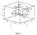
- Fig. 3the measuring axes 3 of the linear acceleration sensors 2 are shown in the body-fixed coordinate system xy, z.
- the coordinates r xi , r yi , r zi of the position vectors r i and the coordinates ⁇ xi , ⁇ yi , ⁇ zi of the direction vectors i of the measuring axes 3are respectively in Fig. 4 listed.
- the index i ⁇ [1, 2, 3, 4,... 12]corresponds to the number of the relevant linear acceleration sensor 2.
- the position vectors r i and the directional vectors ⁇ lare preferably determined by calibration.
- Fig. 9It can be seen that the individual linear acceleration sensors 2 for calculating the vector w and the coordinates of the pivot point C are connected to an evaluation device 8.
- the evaluation devicehas a data memory 9 and a microprocessor 10 which is connected to the data memory 9 via a bus system (not shown in more detail in the drawing).
- the characteristic matrix A -1is stored in the data memory 9.
- W ⁇A x . A y . A z . ⁇ ⁇ x . ⁇ ⁇ y . ⁇ ⁇ z . ⁇ x 2 . ⁇ y 2 . ⁇ z 2 . ⁇ x ⁇ ⁇ y . ⁇ x ⁇ ⁇ z .
Landscapes
- Physics & Mathematics (AREA)
- General Physics & Mathematics (AREA)
- Navigation (AREA)
- Length Measuring Devices With Unspecified Measuring Means (AREA)
Description
Translated fromGermanDie Erfindung betrifft ein Verfahren zur Bestimmung der relativen Lage, Geschwindigkeit und/oder Beschleunigung eines in einem dreidimensionalen Raum bewegbaren Körpers, wobei eine Anzahl von Linearbeschleunigungssensoren, die jeweils eine sensitive Messachse haben, bereitgestellt wird, und wobei die einzelnen Linearbeschleunigungssensoren jeweils an einer zu dem Körper ortsfesten Position Pi angeordnet werden. Außerdem betrifft die Erfindung eine Vorrichtung zur Bestimmung der relativen Lage, Geschwindigkeit und/oder Beschleunigung eines Körpers in einem dreidimensionalen Raum, wobei die Vorrichtung zur Erfassung mindestens eines Beschleunigungsmesssignals
Dabei wird unter einer relativen Lage eine auf eine Bezugsposition, wie z.B. eine Startposition, bezogene Lage verstanden. Unter einem Linearbeschleunigungssensor wird ein unidirektionaler Beschleunigungssensor verstanden, der für Beschleunigungen, die zumindest eine Komponente haben, die auf der Messachse des Linearbeschleunigungssensors liegt, empfindlich ist. Die Linearbeschleunigungssensoren können baulich voneinander getrennt jeweils in einem eigenen Gehäuse angeordnet sei. Es ist aber auch möglich, dass mindestens zwei und insbesondere drei unterschiedliche Messachsen aufweisende Linearbeschleunigungssensoren als multidirektionaler Beschleunigungssensor in ein gemeinsames elektrisches oder elektronisches Bauelement integriert sind.In this case, under a relative position, one is moved to a reference position, e.g. understood a starting position, related situation. A linear acceleration sensor is understood to be a unidirectional acceleration sensor which is sensitive to accelerations which have at least one component which lies on the measuring axis of the linear acceleration sensor. The linear acceleration sensors can be arranged structurally separated from each other in a separate housing. But it is also possible that at least two and in particular three different measuring axes having linear acceleration sensors are integrated as a multidirectional acceleration sensor in a common electrical or electronic component.
Ein Verfahren und eine Vorrichtung zur Bestimmung der Winkelgeschwindigkeit eines drehbaren Körpers, nämlich eines Kraftfahrzeugs, sind aus
Dabei bedeuten:
- A
- die Beschleunigung des Ursprungs des Körperfesten Koordinatensystems,
- t
- die Zeit,
ω̅ - die Winkelgeschwindigkeit des Körpers, und
r - den Positionsvektor, der vom Ursprung des Körperfesten Koordinatensystems zum Punkt P zeigt.
- A
- the acceleration of the origin of the body-fixed coordinate system,
- t
- the time,
w - the angular velocity of the body, and
r - the position vector pointing from the origin of the body-fixed coordinate system to the point P.
Geht man davon aus, dass ein Linearbeschleunigungssensor fest am Punkt P des


Dabei handelt es sich um ein dreidimensionales, nicht lineares Differentialgleichungssystem, das nicht allgemein analytisch lösbar ist. Die Bestimmung der Winkelgeschwindigkeit des drehbaren Körpers erfordert daher einen relativ großen Rechenaufwand. Die nach dem Verfahren arbeitende Vorrichtung ist also entsprechend aufwändig, teuer und trotzdem meist ungenau.This is a three-dimensional, nonlinear system of differential equations that is not generally analytically solvable. The determination of the angular velocity of the rotatable body therefore requires a relatively large computational effort. The device operating according to the method is therefore correspondingly complex, expensive and still mostly inaccurate.
Aus
Es besteht deshalb die Aufgabe, ein Verfahren und eine Vorrichtung der eingangs genannten Art zu schaffen, die auf einfache Weise eine exakte Bestimmung der Lage, Geschwindigkeit und/oder Beschleunigung eines Körpers ermöglichen.It is therefore the object to provide a method and an apparatus of the type mentioned above, which allow a simple way an exact determination of the position, speed and / or acceleration of a body.
Diese Aufgabe wird bezüglich des Verfahrens dadurch gelöst, dass eine Anzahl von n Linearbeschleunigungssensoren, die jeweils eine sensitive Messachse haben, bereitgestellt wird, dass die Anzahl n mindestens zwölf beträgt, dass die einzelnen Linearbeschleunigungssensoren jeweils an einer zu dem Körper ortsfesten Position Pi angeordnet werden, die sich durch einen stationären Positionsvektor


Die Erfindung geht von Gleichung (2) aus, die sich in Vektorschreibweise entsprechend ihrer Anteile in den Körperfesten Koordinaten x, y,z wie folgt schreiben lässt:
Da die einzelnen Linearbeschleunigungssensoren jeweils nur über eine sensitive Messachse mit dem Richtungsvektor Θ̅i verfügen, muss das Skalarprodukt aus Gleichung (4) und Θ̅i gebildet werden. Dies führt zu Gleichung (5), welche die mit dem Linearbeschleunigungssensor i im Punkt Pi gemessene Beschleunigung ai beschreibt:
Betrachtet man die rechte Seite von Gleichung (5) so fällt auf, dass sie aus folgenden zwölf Werten aufgebaut ist, von denen sechs unabhängig sind:
Die restlichen Werte beschreiben die Position
Verwendet man nun eine Anzahl n von mindestens zwölf Linearbeschleunigungssensoren, so erhält man die Messwerte a1 bis an. Schreibt man Gleichung (5) für die n Sensoren untereinander so ergibt sich folgendes Gleichungssystem, das hier aus Platzgründen nur teilweise dargestellt ist
Separiert man die oben genannten zwölf Werte aus der rechten Seite von Gleichung (6), so ergibt sich das in
Um nun aus dem Beschleunigungsmesssignal
In vorteilhafter Weise ermöglicht das erfindungsgemäße Verfahren auch bei schräg zueinander angeordneten Messachsen auf einfache Weise eine exakte Bestimmung der relativen Lage, Geschwindigkeit und/oder Beschleunigung des Körpers, ohne dass ein Differentialgleichungssystem numerisch gelöst werden muss.In an advantageous manner, the method according to the invention also makes it possible to determine the relative position, speed and / or acceleration of the relative position, even if the measuring axes are arranged at an angle to one another Body, without having to solve a differential equation system numerically.
Bei einer bevorzugten Ausgestaltung der Erfindung werden nach dem Anordnen der Linearbeschleunigungssensoren an den Positionen Pi mindestens fünf Messungen durchgeführt, bei denen der Körper in Bezug zu einem Erdfesten Koordinatensystem in unterschiedliche, bekannte Richtungen linear und/oder um mindestens ein bekanntes Drehzentrum beschleunigt wird, wobei bei jeder Messung jeweils ein Beschleunigungsmesssignal
Bei einer vorteilhaften Ausführungsform der Erfindung wird aus dem Geschwindigkeits-Signal die relative Lage eines Drehzentrums ermittelt, um das sich der Köper in dem Raum dreht. Zum Bestimmen des Drehzentrums der Rotationsbewegung wird dabei der Punkt gesucht, an dem die Geschwindigkeit gleich Null ist. Bei einem Kraftfahrzeug kann beispielsweise in Abhängigkeit von der Lage des Drehpunkts relativ zum Zentrum des Kraftfahrzeugs und in Abhängigkeit von der Winkelgeschwindigkeit und/oder Winkelbeschleunigung des Kraftfahrzeugs kann das Auslösen einer zum Schutz der Fahrzeug-Insassen vorgesehenen Sicherheitseinrichtung gesteuert werden.In an advantageous embodiment of the invention, the speed signal determines the relative position of a center of rotation about which the body rotates in the space. In order to determine the center of rotation of the rotational movement while the point is sought, where the speed is zero. In a motor vehicle, for example, depending on the position of the pivot point relative to the center of the motor vehicle and in dependence on the angular velocity and / or angular acceleration of the motor vehicle, the triggering of a safety device provided for protecting the vehicle occupants can be controlled.
Bezüglich der Vorrichtung wird die vorstehend genannte Aufgabe dadurch gelöst, dass die Vorrichtung zur Erfassung mindestens eines Beschleunigungsmesssignals


und
and
Wie bei dem Verfahren bereits erläutert wurde, können die Messachsen der mindestens zwölf Linearbeschleunigungssensoren auch beliebig schräg zueinander angeordnet sein, solange die aus den zwölf Spaltenvektoren
Die Vorrichtung kann ein Teil eines inertialen Navigationssystems (INS) sein. Das Navigationssystem kann zusätzlich auch ein Global Positioning System (GPS) aufweisen, das mehrere die Erde umkreisende Satelliten bekannter Position aufweist. Das inertiale Navigationssystem kommt dabei bevorzugt dann zum Einsatz, wenn die GPS-Positionsbestimmung vorübergehend gestört ist, beispielsweise weil die freie Sicht auf die Satelliten durch ein Hindernis versperrt ist. Durch einen geeigneten mathematischen Filter, insbesondere einen Kalman, einen Extended Kalman und/oder einen Partikel-Filter, kann das dynamische aber nicht langzeitstabile INS mit dem trägen, aber langzeitstabilen GPS verknüpft werden. Dies ermöglicht ein dynamisches und langzeitstabiles System mit besseren Eigenschaften als die entsprechenden Einzelsysteme. Außerdem ist eine Selbstkalibrierung online möglich.The device may be part of an inertial navigation system (INS). The navigation system may additionally include a Global Positioning System (GPS) having multiple satellites of known position orbiting the earth. The inertial navigation system is preferably used when the GPS position determination is temporarily disturbed, for example, because the free view of the satellites is blocked by an obstacle. Through a suitable mathematical filter, in particular a Kalman, an Extended Kalman and / or a particle filter, the dynamic INS but not long-term stable INS can be linked to the sluggish, but long-term stable GPS. This allows a dynamic and long-term stable system with better properties than the corresponding individual systems. In addition, self-calibration is possible online.
Die Verwendung der erfindungsgemäßen Vorrichtung ist nicht auf den Automotivebereich beschränkt. Insbesondere kann die Vorrichtung auch in der Medizintechnik, in einem Luft-und/oder Wasserfahrzeug sowie bei allen anderen Anwendungen, bei denen die Messung der Lage und Bewegung eines Körpers im Raum von Bedeutung ist, zum Einsatz kommen.The use of the device according to the invention is not restricted to the automotive sector. In particular, the device can also be used in medical technology, in an aircraft and / or watercraft as well as in all other applications, where the measurement of the position and movement of a body in space is important, are used.
Bei einer vorteilhaften Ausführungsform der Erfindung weist die Auswerteeinrichtung einen Datenspeicher auf, in dem mindestens ein Kenngrößensignal für einen Zeilenvektor einer Kenngrößenmatrix abgelegt ist, die zu einer zwölfspaltigen, die Spaltenvektoren
Vorteilhaft ist, wenn die Auswerteeinrichtung Mittel zur Bildung wenigstens eines dem Skalarprodukt aus dem mindestens einen Kenngrößensignal und dem Beschleunigungsmesssignal
Bei einer bevorzugten Ausführungsform der Erfindung weist die Auswerteeinrichtung Mittel zur Bildung wenigstens eines, dem Skalarprodukt aus dem mindestens einen Kenngrößensignal und dem Beschleunigungsmesssignal
Bei einer zweckmäßigen Ausgestaltung der Erfindung weist die Auswerteeinrichtung Mittel zum gegebenenfalls zweifachen Integrieren des mindestens einen zweiten Skalarproduktsignals auf. Aus der Winkelbeschleunigung können dann die Winkelgeschwindigkeit und/oder die Drehlage des Körpers in Bezug zu einer Ausgangslage bestimmt werden. Die Vorrichtung kann dabei insbesondere zur Steuerung einer Sicherheitseinrichtung zum Schutz der Insassen eines Kraftfahrzeugs gegen Verletzungen bei einem Überschlag vorgesehen sein. Dabei kann die Vorrichtung insbesondere dazu dienen, den Winkel, den eine vorgegebene Fahrzeugachse, wie z.B. die Längsachse, in Bezug zur Richtung der Erdbeschleunigung aufweist, zu bestimmen, um die Sicherheitseinrichtung bei einem Überschlag zum richtigen Zeitpunkt auszulösen. Je nach dem, ob das Fahrzeug in einer Ebene oder an einem Berg steht, verschiebt sich der kritische Winkel, bei dem ein Überschlag unvermeidlich wird. Zum Entscheiden, welche Maßnahmen bei einem drohenden Überschlag getroffen werden sollen, ist auch die Position der Drehachse im Raum von großer Bedeutung. Befindet sich die Drehachse beispielsweise im Fahrzeuginneren, kann eine andere Sicherheitseinrichtung zum Einsatz kommen, als wenn sich die Drehachse außerhalb befindet. Gerade für eine Sicherheitseinrichtung in einem Kraftfahrzeug ist die Robustheit der Linearbeschleunigungssensoren vom Vorteil, da diese nicht bereits durch einen Aufprall vor dem eigentlichen Überschlag zerstört werden dürfen.In an expedient embodiment of the invention, the evaluation device has means for optionally integrating twice the at least one second scalar product signal. From the angular acceleration then the angular velocity and / or the rotational position of the body can be determined in relation to a starting position. The device may be provided in particular for controlling a safety device to protect the occupants of a motor vehicle against injury in a rollover. In particular, the device may serve to adjust the angle which a given vehicle axle, e.g. to determine the longitudinal axis, with respect to the direction of gravitational acceleration, in order to trigger the safety device in a rollover at the right time. Depending on whether the vehicle is in a plane or on a mountain, the critical angle at which a rollover inevitably shifts. To decide which measures should be taken in the event of a rollover, the position of the rotary axis in the room is also of great importance. For example, if the axis of rotation is inside the vehicle, another safety device may be used than when the axis of rotation is outside. Especially for a safety device in a motor vehicle, the robustness of the linear acceleration sensors is advantageous because they may not already be destroyed by an impact before the actual flashover.
Bei einer vorteilhaften Ausführungsform der Erfindung weist die Auswerteeinrichtung Mittel zur Bildung wenigstens eines dem Skalarprodukt aus dem mindestens einen Kenngrößensignal und dem Beschleunigungsmesssignal
Vorteilhaft ist, wenn die Auswerteeinrichtung Mittel zur Bildung wenigstens eines dem Skalarprodukt aus dem mindestens einen Kenngrößensignal und dem Beschleunigungsmesssignal
Zweckmäßigerweise ist die Vergleichseinrichtung zum Vergleichen des Quadratwurzelsignals mit dem durch Integration des mindestens einen zweiten Skalarproduktsignals gebildeten Signals ausgestaltet und hat einen Ausgang für ein von dem Ergebnis des Vergleichs abhängiges Fehlerstatussignal. Die Plausibilität der Messergebnisse kann dann noch besser überprüft werden.The comparison device is expediently designed to compare the square root signal with the signal formed by integration of the at least one second dot signal and has an output for an error status signal dependent on the result of the comparison. The plausibility of the measurement results can then be checked even better.
Vorteilhaft ist, wenn die Auswerteeinrichtung Mittel zur Integration des zweiten Skalarproduktsignal und zur Bildung des Quadrats aus dem Ergebnis dieses Integration aufweist, wenn diese Mittel zum Vergleichen des so erhaltenen Signals mit dem dritten Skalarproduktsignal mit der Vergleichseinrichtung verbunden ist, und wenn die Vergleichseinrichtung einen Ausgang für ein von dem Ergebnis des Vergleichs abhängiges Fehlerstatussignal hat. Es wird also die Plausibilität des zweiten und dritten Skalarproduktsignals überprüft.It is advantageous if the evaluation device has means for integrating the second dot product signal and for forming the square from the result of this integration, if this means for comparing the signal thus obtained with the third dot product signal is connected to the comparison device, and if the comparison device has an output for has an error status signal dependent on the result of the comparison. Thus, the plausibility of the second and third scalar product signal is checked.
Bei einer bevorzugten Ausgestaltung der Erfindung weist die Auswerteeinrichtung zum Differenzieren des Quadratwurzelsignals eine Differenziereinrichtung auf, wobei die Differenziereinrichtung zum Vergleichen des differenzierten Signals mit dem zweiten Skalarproduktsignal mit der Vergleichseinrichtung verbunden ist, und wobei die Vergleichseinrichtung einen Ausgang für ein von dem Ergebnis des Vergleichs abhängiges Fehlerstatussignal hat. Auch diese Maßnahme ermöglicht eine einfache und schnelle Plausibilitätsprüfung der Messergebnisse.In a preferred embodiment of the invention, the evaluation device for differentiating the square root signal to a differentiating device, wherein the differentiator for comparing the differentiated signal with the second scalar product signal is connected to the comparator, and wherein the comparator has an output for an error status signal dependent on the result of the comparison. This measure also allows a simple and quick plausibility check of the measurement results.
Nachfolgend ist ein Ausführungsbeispiel der Erfindung anhand der Zeichnung näher erläutert. Es zeigen:
- Fig. 1a bis 1c
- ein zwei Vektoren und eine Matrix aufweisendes Gleichungssystem für zwölf Linearbeschleunigungssensoren,
- Fig. 2
- eine schematische Darstellung eines in einem dreidimensionalen Raum in Richtung der drei Achsen u, v, w eines kartesischen Erdfesten Koordinatensystems verschiebbaren und um diese Achsen verdrehbaren Körpers,
- Fig. 3
- eine schematische Darstellung der Messachsen von an dem Körper an abgebrachten Linearbeschleunigungssensoren in einem Körperfesten Koordinatensystem mit den Achsen x, y und z,
- Fig. 4
- eine Tabelle, in der die Positionen der Linearbeschleunigungssensoren in den Koordinaten des Körperfesten kartesischen Koordinatensystems aufgeführt sind,
- Fig. 5
- eine Tabelle, in der die Richtungen, in denen die Linearbeschleunigungssensoren empfindlich sind, in den Koordinaten des Körperfesten kartesischen Koordinatensystems aufgeführt sind,
- Fig. 6
- die Matrix aus dem in
Fig. 2 abgebildeten Gleichungssystem für die inFig. 3 gezeigte Anordnung von Linearbeschleunigungssensoren, - Fig. 7
- eine Matrix, die zu der in
Fig. 6 abgebildeten Matrix invers ist, - Fig. 8
- ein Vektorfeld, das Geschwindigkeitsvektoren für eine Bewegung eines Körpers enthält, die eine translatorische und eine rotatorische Komponente aufweist, wobei das Drehzentrum der rotatorischen Bewegung mit C bezeichnet ist, und
- Fig. 9
- ein Blockschaltbild einer Vorrichtung zur Bestimmung der Lage, Geschwindigkeit, Beschleunigung und/oder des Drehzentrums eines Körpers in einem dreidimensionalen Raum.
- Fig. 1a to 1c
- a two vector and one matrix system of equations for twelve linear acceleration sensors,
- Fig. 2
- a schematic representation of a displaceable in a three-dimensional space in the direction of the three axes u, v, w of a Cartesian Erdfesten coordinate system and rotatable about these axes body,
- Fig. 3
- 2 is a schematic representation of the measuring axes of linear acceleration sensors deployed on the body in a body-fixed coordinate system with the axes x, y and z,
- Fig. 4
- a table in which the positions of the linear acceleration sensors are listed in the coordinates of the body-fixed Cartesian coordinate system,
- Fig. 5
- a table in which the directions in which the linear acceleration sensors are sensitive are listed in the coordinates of the body-fixed Cartesian coordinate system,
- Fig. 6
- the matrix from the in
Fig. 2 illustrated equation system for the inFig. 3 shown arrangement of linear acceleration sensors, - Fig. 7
- a matrix that belongs to the in
Fig. 6 mapped matrix is inverse, - Fig. 8
- a vector field containing velocity vectors for a movement of a body having a translational and a rotational component, wherein the center of rotation of the rotational movement is denoted by C, and
- Fig. 9
- a block diagram of a device for determining the position, speed, acceleration and / or the center of rotation of a body in a three-dimensional space.
Eine Vorrichtung zur Bestimmung der relativen Lage, Geschwindigkeit, Beschleunigung und ggf. des Drehzentrums eines in einem dreidimensionalen, durch die Koordinaten u, v, w eines Raum- oder Erdfesten Koordinatensystems aufgespannten Raum (
In
In
Aus
Setzt man die Koordinaten rxi, ryi, rzi der zwölf Positionsvektoren
Mit Hilfe der KenngrößenmatrixA-1 lässt sich nun nach Gleichung (8) der Vektor


Um den Drehpunkt eines Körpers bestimmen zu können müssen die Translationsgeschwindigkeit

In

Bei dem Verfahren zur Bestimmung der relativen Lage, Geschwindigkeit, Beschleunigung und/oder des Drehzentrums eines In einem dreidimensionalen Raum bewegbaren Körpers 1 werden also mindestens zwölf Linearbeschleunigungssensoren 2 bereitgestellt und jeweils an einer zu dem Körper 1 ortsfesten Position angeordnet. Mit Hilfe der Linearbeschleunigungssensoren 2 wird mindestens ein Beschleunigungsmesssignal erfasst. Aus dem Beschleunigungsmesssignal und Kenngrößen, welche die Lage und Orientierung der Linearbeschleunigungssensoren 2 in dem Körperfesten Koordinatensystem beschreiben, wird ein Lage-, Geschwindigkeits-, Beschleunigungs- und/oder Drehzentrum-Signal für den Körper 1 gebildet.In the method for determining the relative position, speed, acceleration and / or the center of rotation of a movable in a three-
Claims (15)
- Method for determining the relative position, velocity, and/or acceleration of a body (1) displaceable in a three dimensional space, wherein a plurality of n linear acceleration sensors (2), which in each case have a sensitive measurement axis (3), is provided, wherein said plurality n is at least twelve, wherein the individual linear acceleration sensors (2) are in each case arranged on a position Pi which is stationarily fixed with respect to the body (1) and which can be described by a stationary position vector,


r ¡ and the direction vectorsΘ i are selected so that the rank of a twelve column matrix formed from the column vectors


- Method as in claim 1,characterized in that after the arrangement of the linear acceleration signals (2) on the positions Pi , at least five measurements are taken in which the body (1) is accelerated linearly and/or about at least one known rotation center in various known directions with respect to an earth-fixed coordinate system,in that with each measurement an acceleration measurement signal

a k and the directions and/or the at least one rotation center. - Method as in claim 1 or 2,characterized in that the relative position of a rotation center about which the body rotates in the space is determined from the velocity signal.
- Device for determining the relative position, velocity, and/or acceleration of a body (1) displaceable in a three dimensional space, wherein the device for the capture of at least one acceleration measurement signal


r i and the direction vectorsΘ i are selected so that the rank of a twelve column matrix formed from the column vectors


a and data that describe the relative position and orientation of the linear acceleration sensors (2) in the body-fixed coordinate system. - Device as in claim 4,characterized in that the evaluator has a data storage (9) in which at least one data signal for a line vector of a data matrix is filed, which is the inverse of a twelve column matrix comprising the column vectors
s 1,s 2,s 3,s 4,s 5,s 6,s 7,s 8,s 9,s 10,s 11,s 12. - Device as in claim 5,characterized in that the evaluator (8) has means for generating at least one first scalar product signal corresponding to the scalar product from the at least one data signal and the acceleration measurement signal
a , andin that the at least one data signal is selected so that the at least one first scalar product signal corresponds to a vectorial component of the translatory acceleration of the body (1). - Device as in claim 5 or 6,characterized in that the evaluator (8) has means for generating at least one second scalar product signal corresponding to the scalar product from the at least one data signal and the acceleration measurement signal
a , andin that the at least one data signal is selected so that the second scalar product signal corresponds to a vectorial component of the angulatory acceleration of the body (1). - Device as in any one of claims 5 through 7,characterized in that the evaluator (8) has means, should the need arise, for the two-fold integration of the at least one second scalar product signal.
- Device as in any one of claims 5 through 8,characterized in that the evaluator (8) has means for generating at least one third scalar product signal corresponding to the scalar product from the at least one data signal and the acceleration measurement signal
a ,in that the at least one data signal is selected so that the third scalar product signal corresponds to the square of a vectorial component of the angular velocity of the body (1), andin that the evaluator (8) has means for generating a square root signal from the scalar product signal. - Device as in any one of claims 5 through 9,characterized in that the evaluator (8) has means for generating at least one fourth scalar product signal corresponding to the scalar product from the at least one data signal and the acceleration measurement signal
a ,in that the at least one data signal is selected so that the fourth scalar product signal corresponds to the product of two different vectorial components of the angular velocity of the body (1),in that the evaluator (8) has means for integration of the scalar product signals detected in each case for the respective vectorial components and for the generation of at least one product signal from the results of these integrations,in that the evaluator (8) has a comparison mechanism for comparing the magnitude of this product signal with the fourth scalar product signal, andin that the comparison mechanism has an output for an error status signal dependent on the result of the comparison. - Device as in any one of claims 5 through 10,characterized in that the comparison mechanism is configured to compare the square root signal with the signal generated by integration of the at least one second scalar product signal, andin that the comparison mechanism has an output for an error status signal dependent on the result of the comparison.
- Device as in any one of claims 5 through 11,characterized in that the evaluator has means for the integration of the second scalar product signal and for the formation of the square from the result of said integration,in that said means for comparing the signal thus received with the third scalar product signal is connected to the comparison mechanism, andin that the comparison mechanism has an output for an error status signal dependent on the result of the comparison.
- Device as in any one of claims 5 through 12,characterized in that the evaluator has a differentiation mechanism for the differentiation of the square root signal,in that the differentiation mechanism for comparing the differentiated signal with the second scalar product signal is connected to the comparison mechanism, andin that the comparison mechanism has an output for an error status signal dependent on the result of the comparison.
- Device as in any one of claims 4 through 12,characterized in that the evaluator (8) is configured so that in the event of a rotary motion of the body about a rotation center it generates a signal for the relative position of a rotation center from the velocity signal.
- Device as in any one of claims 4 through 14,characterized in that it comprises the body (1) and that the body (1) is a vehicle.


Applications Claiming Priority (2)
| Application Number | Priority Date | Filing Date | Title |
|---|---|---|---|
| DE102005025478ADE102005025478B4 (en) | 2005-06-03 | 2005-06-03 | Method and device for determining the relative position, speed and / or acceleration of a body |
| PCT/EP2006/004749WO2006128592A1 (en) | 2005-06-03 | 2006-05-19 | Method and device for determining the relative position, speed and/or acceleration of a body |
Publications (2)
| Publication Number | Publication Date |
|---|---|
| EP1889006A1 EP1889006A1 (en) | 2008-02-20 |
| EP1889006B1true EP1889006B1 (en) | 2013-09-25 |
Family
ID=36930415
Family Applications (1)
| Application Number | Title | Priority Date | Filing Date |
|---|---|---|---|
| EP06753731.6AActiveEP1889006B1 (en) | 2005-06-03 | 2006-05-19 | Method and device for determining the relative position, speed and/or acceleration of a body |
Country Status (5)
| Country | Link |
|---|---|
| US (1) | US8037759B2 (en) |
| EP (1) | EP1889006B1 (en) |
| DE (1) | DE102005025478B4 (en) |
| ES (1) | ES2435524T3 (en) |
| WO (1) | WO2006128592A1 (en) |
Families Citing this family (9)
| Publication number | Priority date | Publication date | Assignee | Title |
|---|---|---|---|---|
| IL195104A (en)* | 2008-11-04 | 2013-07-31 | Dekel Tzidon | Device and method for combining samples from an inertial measurement sensor cluster |
| EP2221623A1 (en)* | 2009-02-19 | 2010-08-25 | Sintesi SCpA | Method for estimating the angular acceleration and related inertial measurement unit |
| WO2011153421A2 (en) | 2010-06-03 | 2011-12-08 | Hillcrest Laboratories Inc. | Determining forward pointing direction of a handheld device |
| EP2716117B1 (en)* | 2011-06-27 | 2016-02-24 | Google, Inc. | Gps and mems hybrid location-detection architecture |
| US8362949B2 (en) | 2011-06-27 | 2013-01-29 | Google Inc. | GPS and MEMS hybrid location-detection architecture |
| DE102015216970B4 (en) | 2015-09-04 | 2023-11-02 | Robert Bosch Gmbh | Method for determining the position and orientation of a vehicle |
| CN106768631B (en)* | 2016-12-22 | 2019-01-29 | 西安交通大学 | A kind of Three dimensional rotation amount test device and test method based on acceleration analysis |
| IT201700047233A1 (en)* | 2017-05-02 | 2018-11-02 | Ids Georadar S R L | Method perfected for the execution of georadar surveys and related equipment |
| DK3572819T3 (en) | 2018-05-25 | 2020-12-07 | Hottinger Brueel & Kjær As | PROCEDURE FOR DETERMINING SPATIAL CONFIGURATIONS OF A MAJORITY OF TRANSDUCERS RELATING TO A MEASUREMENT |
Family Cites Families (5)
| Publication number | Priority date | Publication date | Assignee | Title |
|---|---|---|---|---|
| CA1061132A (en)* | 1974-11-29 | 1979-08-28 | Theodore Mairson | Apparatus for performing inertial measurements using translational acceleration transducers and for calibrating translational acceleration transducers |
| DE19856303A1 (en) | 1998-07-16 | 2000-01-27 | Continental Teves Ag & Co Ohg | Determining angle of tilt when cornering as measure of incipient rollover hazard employs single sensor measuring transverse rather than horizontal radial acceleration, from which tilt is computed |
| US6128955A (en)* | 1999-07-09 | 2000-10-10 | Mimura; Nobuharu | Method for measuring 6 degrees of freedom motion and device therefor |
| DE19962687C2 (en)* | 1999-12-23 | 2002-04-18 | Siemens Ag | Method and system for determining the angular acceleration of a body rotating about a predetermined axis of rotation, in particular of a motor vehicle rotating about its longitudinal axis |
| US6584388B2 (en) | 2001-11-08 | 2003-06-24 | Delphi Technologies, Inc. | Adaptive rollover detection apparatus and method |
- 2005
- 2005-06-03DEDE102005025478Apatent/DE102005025478B4/ennot_activeExpired - Fee Related
- 2006
- 2006-05-19ESES06753731Tpatent/ES2435524T3/enactiveActive
- 2006-05-19WOPCT/EP2006/004749patent/WO2006128592A1/enactiveApplication Filing
- 2006-05-19EPEP06753731.6Apatent/EP1889006B1/enactiveActive
- 2006-05-19USUS11/916,377patent/US8037759B2/enactiveActive
Also Published As
| Publication number | Publication date |
|---|---|
| WO2006128592A1 (en) | 2006-12-07 |
| DE102005025478B4 (en) | 2007-04-19 |
| DE102005025478A1 (en) | 2006-12-14 |
| US8037759B2 (en) | 2011-10-18 |
| EP1889006A1 (en) | 2008-02-20 |
| US20100005885A1 (en) | 2010-01-14 |
| ES2435524T3 (en) | 2013-12-20 |
Similar Documents
| Publication | Publication Date | Title |
|---|---|---|
| EP1889006B1 (en) | Method and device for determining the relative position, speed and/or acceleration of a body | |
| DE102017105305B4 (en) | METHOD FOR AUTOMATIC DETERMINATION OF A SENSOR POSITION | |
| EP1870669B1 (en) | Method for checking the inert measuring unit of vehicles, in particular of aircrafts, in the stationary state | |
| DE102016225140B3 (en) | Method for determining a relative position of a motor vehicle, position determination system for a motor vehicle and motor vehicle | |
| EP0341447B1 (en) | Device for determining the influence of cross wind on vehicles | |
| DE102019214544A1 (en) | Method and device for determining a desired position of an environmental sensor of a vehicle | |
| DE102012014312A1 (en) | Robot guided measuring arrangement | |
| DE102020109787A1 (en) | Determining an angular position of a component of a motor vehicle | |
| DE102019132150A1 (en) | Method for automatically calibrating an environment sensor, in particular a lidar sensor, of a vehicle on the basis of occupancy cards and computing device | |
| EP4239294A1 (en) | Method for calibrating a portable reference sensor system, portable reference sensor system, and use of the portable reference sensor system | |
| DE202014009461U1 (en) | Steering angle detection device of a motor vehicle | |
| DE102007051204A1 (en) | Method or control system (component) for transforming and / or recalculating movement quantities, in particular body movements of a body | |
| EP2977297A1 (en) | Method for determination of a steering angle of a motor vehicle, driver assistance system and motor vehicle | |
| EP2838700B1 (en) | Movement system state | |
| DE102008058866B4 (en) | Device and method for determining the position of an object | |
| EP4008497A1 (en) | Validation of a pose of a robot | |
| DE102004004491A1 (en) | Device for determining a rotational speed | |
| EP1873552A1 (en) | Method and device for determining the vertical or horizontal angle error of an all-round sensor in a motor vehicle | |
| EP3578995B1 (en) | Method for online calibration of a sensor of a vehicle | |
| DE102009002214A1 (en) | Vehicle e.g. car, rotary motion determining method, involves determining rotational angle from kinematic relation of actual positions of acceleration sensors around which vehicle is turned during movement | |
| EP1725880A1 (en) | Sensor arrangement | |
| EP3433582B1 (en) | Apparatus for inputting absolute position and orientation of an input element | |
| DE102019132151A1 (en) | Method for calibrating an environment sensor of a vehicle on the basis of data from a reference environment sensor, taking into account occupancy cards, computing device and sensor system | |
| DE112020001834T5 (en) | Reference position setting method and operation detection device | |
| DE102020202154A1 (en) | Determination of dynamic variables of a vehicle with sensors arranged in a distributed manner |
Legal Events
| Date | Code | Title | Description |
|---|---|---|---|
| PUAI | Public reference made under article 153(3) epc to a published international application that has entered the european phase | Free format text:ORIGINAL CODE: 0009012 | |
| 17P | Request for examination filed | Effective date:20071219 | |
| AK | Designated contracting states | Kind code of ref document:A1 Designated state(s):AT BE BG CH CY CZ DE DK EE ES FI FR GB GR HU IE IS IT LI LT LU LV MC NL PL PT RO SE SI SK TR | |
| DAX | Request for extension of the european patent (deleted) | ||
| REG | Reference to a national code | Ref country code:DE Ref legal event code:R079 Ref document number:502006013235 Country of ref document:DE Free format text:PREVIOUS MAIN CLASS: G01C0021160000 Ipc:G01P0003220000 | |
| GRAP | Despatch of communication of intention to grant a patent | Free format text:ORIGINAL CODE: EPIDOSNIGR1 | |
| RIC1 | Information provided on ipc code assigned before grant | Ipc:G01P 15/18 20130101ALI20121205BHEP Ipc:G01P 3/22 20060101AFI20121205BHEP Ipc:G01P 7/00 20060101ALI20121205BHEP Ipc:G01P 15/08 20060101ALI20121205BHEP | |
| GRAP | Despatch of communication of intention to grant a patent | Free format text:ORIGINAL CODE: EPIDOSNIGR1 | |
| INTG | Intention to grant announced | Effective date:20130617 | |
| GRAS | Grant fee paid | Free format text:ORIGINAL CODE: EPIDOSNIGR3 | |
| GRAA | (expected) grant | Free format text:ORIGINAL CODE: 0009210 | |
| RAP1 | Party data changed (applicant data changed or rights of an application transferred) | Owner name:ALBERT-LUDWIGS-UNIVERSITAET FREIBURG | |
| AK | Designated contracting states | Kind code of ref document:B1 Designated state(s):AT BE BG CH CY CZ DE DK EE ES FI FR GB GR HU IE IS IT LI LT LU LV MC NL PL PT RO SE SI SK TR | |
| REG | Reference to a national code | Ref country code:GB Ref legal event code:FG4D Free format text:NOT ENGLISH | |
| REG | Reference to a national code | Ref country code:CH Ref legal event code:EP | |
| REG | Reference to a national code | Ref country code:AT Ref legal event code:REF Ref document number:633911 Country of ref document:AT Kind code of ref document:T Effective date:20131015 | |
| REG | Reference to a national code | Ref country code:IE Ref legal event code:FG4D Free format text:LANGUAGE OF EP DOCUMENT: GERMAN | |
| REG | Reference to a national code | Ref country code:DE Ref legal event code:R096 Ref document number:502006013235 Country of ref document:DE Effective date:20131128 | |
| REG | Reference to a national code | Ref country code:ES Ref legal event code:FG2A Ref document number:2435524 Country of ref document:ES Kind code of ref document:T3 Effective date:20131220 | |
| PG25 | Lapsed in a contracting state [announced via postgrant information from national office to epo] | Ref country code:LT Free format text:LAPSE BECAUSE OF FAILURE TO SUBMIT A TRANSLATION OF THE DESCRIPTION OR TO PAY THE FEE WITHIN THE PRESCRIBED TIME-LIMIT Effective date:20130925 Ref country code:SE Free format text:LAPSE BECAUSE OF FAILURE TO SUBMIT A TRANSLATION OF THE DESCRIPTION OR TO PAY THE FEE WITHIN THE PRESCRIBED TIME-LIMIT Effective date:20130925 | |
| REG | Reference to a national code | Ref country code:NL Ref legal event code:VDEP Effective date:20130925 | |
| REG | Reference to a national code | Ref country code:LT Ref legal event code:MG4D | |
| PG25 | Lapsed in a contracting state [announced via postgrant information from national office to epo] | Ref country code:LV Free format text:LAPSE BECAUSE OF FAILURE TO SUBMIT A TRANSLATION OF THE DESCRIPTION OR TO PAY THE FEE WITHIN THE PRESCRIBED TIME-LIMIT Effective date:20130925 Ref country code:SI Free format text:LAPSE BECAUSE OF FAILURE TO SUBMIT A TRANSLATION OF THE DESCRIPTION OR TO PAY THE FEE WITHIN THE PRESCRIBED TIME-LIMIT Effective date:20130925 Ref country code:FI Free format text:LAPSE BECAUSE OF FAILURE TO SUBMIT A TRANSLATION OF THE DESCRIPTION OR TO PAY THE FEE WITHIN THE PRESCRIBED TIME-LIMIT Effective date:20130925 Ref country code:GR Free format text:LAPSE BECAUSE OF FAILURE TO SUBMIT A TRANSLATION OF THE DESCRIPTION OR TO PAY THE FEE WITHIN THE PRESCRIBED TIME-LIMIT Effective date:20131226 | |
| PG25 | Lapsed in a contracting state [announced via postgrant information from national office to epo] | Ref country code:EE Free format text:LAPSE BECAUSE OF FAILURE TO SUBMIT A TRANSLATION OF THE DESCRIPTION OR TO PAY THE FEE WITHIN THE PRESCRIBED TIME-LIMIT Effective date:20130925 Ref country code:NL Free format text:LAPSE BECAUSE OF FAILURE TO SUBMIT A TRANSLATION OF THE DESCRIPTION OR TO PAY THE FEE WITHIN THE PRESCRIBED TIME-LIMIT Effective date:20130925 Ref country code:SK Free format text:LAPSE BECAUSE OF FAILURE TO SUBMIT A TRANSLATION OF THE DESCRIPTION OR TO PAY THE FEE WITHIN THE PRESCRIBED TIME-LIMIT Effective date:20130925 Ref country code:IS Free format text:LAPSE BECAUSE OF FAILURE TO SUBMIT A TRANSLATION OF THE DESCRIPTION OR TO PAY THE FEE WITHIN THE PRESCRIBED TIME-LIMIT Effective date:20140125 Ref country code:RO Free format text:LAPSE BECAUSE OF FAILURE TO SUBMIT A TRANSLATION OF THE DESCRIPTION OR TO PAY THE FEE WITHIN THE PRESCRIBED TIME-LIMIT Effective date:20130925 | |
| PG25 | Lapsed in a contracting state [announced via postgrant information from national office to epo] | Ref country code:PL Free format text:LAPSE BECAUSE OF FAILURE TO SUBMIT A TRANSLATION OF THE DESCRIPTION OR TO PAY THE FEE WITHIN THE PRESCRIBED TIME-LIMIT Effective date:20130925 Ref country code:CY Free format text:LAPSE BECAUSE OF FAILURE TO SUBMIT A TRANSLATION OF THE DESCRIPTION OR TO PAY THE FEE WITHIN THE PRESCRIBED TIME-LIMIT Effective date:20130925 | |
| REG | Reference to a national code | Ref country code:DE Ref legal event code:R097 Ref document number:502006013235 Country of ref document:DE | |
| PG25 | Lapsed in a contracting state [announced via postgrant information from national office to epo] | Ref country code:PT Free format text:LAPSE BECAUSE OF FAILURE TO SUBMIT A TRANSLATION OF THE DESCRIPTION OR TO PAY THE FEE WITHIN THE PRESCRIBED TIME-LIMIT Effective date:20140127 | |
| PLBE | No opposition filed within time limit | Free format text:ORIGINAL CODE: 0009261 | |
| STAA | Information on the status of an ep patent application or granted ep patent | Free format text:STATUS: NO OPPOSITION FILED WITHIN TIME LIMIT | |
| 26N | No opposition filed | Effective date:20140626 | |
| PG25 | Lapsed in a contracting state [announced via postgrant information from national office to epo] | Ref country code:DK Free format text:LAPSE BECAUSE OF FAILURE TO SUBMIT A TRANSLATION OF THE DESCRIPTION OR TO PAY THE FEE WITHIN THE PRESCRIBED TIME-LIMIT Effective date:20130925 | |
| REG | Reference to a national code | Ref country code:DE Ref legal event code:R097 Ref document number:502006013235 Country of ref document:DE Effective date:20140626 | |
| PG25 | Lapsed in a contracting state [announced via postgrant information from national office to epo] | Ref country code:LU Free format text:LAPSE BECAUSE OF FAILURE TO SUBMIT A TRANSLATION OF THE DESCRIPTION OR TO PAY THE FEE WITHIN THE PRESCRIBED TIME-LIMIT Effective date:20140519 | |
| REG | Reference to a national code | Ref country code:CH Ref legal event code:PL | |
| PG25 | Lapsed in a contracting state [announced via postgrant information from national office to epo] | Ref country code:LI Free format text:LAPSE BECAUSE OF NON-PAYMENT OF DUE FEES Effective date:20140531 Ref country code:MC Free format text:LAPSE BECAUSE OF FAILURE TO SUBMIT A TRANSLATION OF THE DESCRIPTION OR TO PAY THE FEE WITHIN THE PRESCRIBED TIME-LIMIT Effective date:20130925 Ref country code:CH Free format text:LAPSE BECAUSE OF NON-PAYMENT OF DUE FEES Effective date:20140531 | |
| REG | Reference to a national code | Ref country code:IE Ref legal event code:MM4A | |
| PG25 | Lapsed in a contracting state [announced via postgrant information from national office to epo] | Ref country code:IE Free format text:LAPSE BECAUSE OF NON-PAYMENT OF DUE FEES Effective date:20140519 | |
| REG | Reference to a national code | Ref country code:AT Ref legal event code:MM01 Ref document number:633911 Country of ref document:AT Kind code of ref document:T Effective date:20140519 | |
| PG25 | Lapsed in a contracting state [announced via postgrant information from national office to epo] | Ref country code:AT Free format text:LAPSE BECAUSE OF NON-PAYMENT OF DUE FEES Effective date:20140519 | |
| REG | Reference to a national code | Ref country code:FR Ref legal event code:PLFP Year of fee payment:11 | |
| PG25 | Lapsed in a contracting state [announced via postgrant information from national office to epo] | Ref country code:BG Free format text:LAPSE BECAUSE OF FAILURE TO SUBMIT A TRANSLATION OF THE DESCRIPTION OR TO PAY THE FEE WITHIN THE PRESCRIBED TIME-LIMIT Effective date:20130925 | |
| PG25 | Lapsed in a contracting state [announced via postgrant information from national office to epo] | Ref country code:TR Free format text:LAPSE BECAUSE OF FAILURE TO SUBMIT A TRANSLATION OF THE DESCRIPTION OR TO PAY THE FEE WITHIN THE PRESCRIBED TIME-LIMIT Effective date:20130925 Ref country code:HU Free format text:LAPSE BECAUSE OF FAILURE TO SUBMIT A TRANSLATION OF THE DESCRIPTION OR TO PAY THE FEE WITHIN THE PRESCRIBED TIME-LIMIT; INVALID AB INITIO Effective date:20060519 | |
| REG | Reference to a national code | Ref country code:FR Ref legal event code:PLFP Year of fee payment:12 | |
| REG | Reference to a national code | Ref country code:FR Ref legal event code:PLFP Year of fee payment:13 | |
| REG | Reference to a national code | Ref country code:DE Ref legal event code:R082 Ref document number:502006013235 Country of ref document:DE | |
| PGFP | Annual fee paid to national office [announced via postgrant information from national office to epo] | Ref country code:DE Payment date:20250519 Year of fee payment:20 | |
| PGFP | Annual fee paid to national office [announced via postgrant information from national office to epo] | Ref country code:ES Payment date:20250616 Year of fee payment:20 Ref country code:GB Payment date:20250522 Year of fee payment:20 | |
| PGFP | Annual fee paid to national office [announced via postgrant information from national office to epo] | Ref country code:BE Payment date:20250520 Year of fee payment:20 Ref country code:IT Payment date:20250530 Year of fee payment:20 | |
| PGFP | Annual fee paid to national office [announced via postgrant information from national office to epo] | Ref country code:FR Payment date:20250521 Year of fee payment:20 | |
| PGFP | Annual fee paid to national office [announced via postgrant information from national office to epo] | Ref country code:CZ Payment date:20250506 Year of fee payment:20 |