EP1888144B1 - Implantable infusion device with multiple controllable fluid outlets - Google Patents
Implantable infusion device with multiple controllable fluid outletsDownload PDFInfo
- Publication number
- EP1888144B1 EP1888144B1EP06771202AEP06771202AEP1888144B1EP 1888144 B1EP1888144 B1EP 1888144B1EP 06771202 AEP06771202 AEP 06771202AEP 06771202 AEP06771202 AEP 06771202AEP 1888144 B1EP1888144 B1EP 1888144B1
- Authority
- EP
- European Patent Office
- Prior art keywords
- fluid
- infusion device
- reservoir
- fluid transfer
- actuation mode
- Prior art date
- Legal status (The legal status is an assumption and is not a legal conclusion. Google has not performed a legal analysis and makes no representation as to the accuracy of the status listed.)
- Ceased
Links
Images


Classifications
- A—HUMAN NECESSITIES
- A61—MEDICAL OR VETERINARY SCIENCE; HYGIENE
- A61M—DEVICES FOR INTRODUCING MEDIA INTO, OR ONTO, THE BODY; DEVICES FOR TRANSDUCING BODY MEDIA OR FOR TAKING MEDIA FROM THE BODY; DEVICES FOR PRODUCING OR ENDING SLEEP OR STUPOR
- A61M5/00—Devices for bringing media into the body in a subcutaneous, intra-vascular or intramuscular way; Accessories therefor, e.g. filling or cleaning devices, arm-rests
- A61M5/14—Infusion devices, e.g. infusing by gravity; Blood infusion; Accessories therefor
- A61M5/142—Pressure infusion, e.g. using pumps
- A61M5/14244—Pressure infusion, e.g. using pumps adapted to be carried by the patient, e.g. portable on the body
- A61M5/14276—Pressure infusion, e.g. using pumps adapted to be carried by the patient, e.g. portable on the body specially adapted for implantation
- A—HUMAN NECESSITIES
- A61—MEDICAL OR VETERINARY SCIENCE; HYGIENE
- A61M—DEVICES FOR INTRODUCING MEDIA INTO, OR ONTO, THE BODY; DEVICES FOR TRANSDUCING BODY MEDIA OR FOR TAKING MEDIA FROM THE BODY; DEVICES FOR PRODUCING OR ENDING SLEEP OR STUPOR
- A61M5/00—Devices for bringing media into the body in a subcutaneous, intra-vascular or intramuscular way; Accessories therefor, e.g. filling or cleaning devices, arm-rests
- A61M5/14—Infusion devices, e.g. infusing by gravity; Blood infusion; Accessories therefor
- A61M5/168—Means for controlling media flow to the body or for metering media to the body, e.g. drip meters, counters ; Monitoring media flow to the body
- A61M5/16804—Flow controllers
- A61M5/16827—Flow controllers controlling delivery of multiple fluids, e.g. sequencing, mixing or via separate flow-paths
Definitions
- the present inventionsrelate generally to implantable infusion devices.
- Implantable infusion devicestypically include a housing containing a medication reservoir which can be filled transcutaneously by a hypodermic needle penetrating a fill port septum.
- the medication reservoiris generally coupled via an internal flow path to a device outlet port for delivering medication through a catheter to a patient body site.
- Typical infusion devicesalso include a controller and a fluid transfer mechanism, such as a pump or a valve, for moving the medication from the reservoir through the internal flow path to the device's outlet port.
- a fluid transfer mechanismsuch as a pump or a valve
- US 2002/156462 A1discloses a programmable implantable pump with accessory reservoirs, a patient controller, and a multiple independent lumen catheter.
- US 2002/188327 A1discloses drug delivery for treatment of cardiac arrhythmia with automatic administration of anti-arrhythmia drugs infused into a patient's body by an implantable drug delivery system.
- US 3 923 060 Adiscloses an apparatus for dispensing drugs and other medications within a patient's body, which apparatus is adapted to be entirely implanted and to dispense such substances via a self-powered dispensing device over a long period of time, e.g., one to several years, in accordance with the actual needs of the patient.
- the present inventionsprovide an implantable infusion device having the technical features as described in the independent claim. Preferred embodiments of the present inventions are described in the dependent claims.
- the implantable infusion device in accordance with the present inventionincludes multiple fluid transfer devices that are actuated by a common actuator. Such a device is particularly advantageous because it greatly reduces the amount of space within the device that must be dedicated to the actuation of the fluid transfer devices.
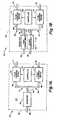
- an implantable infusion device 20in accordance with one embodiment of a present invention includes an outer shell 22 enveloping an interior volume 24.
- the fluid reservoir 26 in the illustrated embodimentsupplies two separate fluid transfer devices. More specifically, the fluid reservoir 26 includes a discharge port 30 that is coupled to a first fluid transfer path 31 including a first fluid transfer device 32. The discharge port 30 is also coupled to a second fluid transfer path 34 including a second fluid transfer device 35.
- the first fluid transfer device 32defines an inlet 36 and an outlet 37.
- the second fluid transfer device 35defines an inlet 38 and an outlet 39.
- the outlets 37 and 39open through the outer shell 22 and are adapted to communicate with respective catheters for delivering medication from the reservoir 26 to the same or different body sites.
- the exemplary fluid transfer devices 32 and 35are controllable devices, such as selectively actuatable pumps and/or valve mechanisms, which can be independently operated by a common controller 44, such as a microprocessor, in accordance with different stored medication profiles, or protocols, that are accessible by the common controller.
- a common controller 44such as a microprocessor
- Each such profilecan, for example, define delivery start times, delivery durations, delivery rates and other parameters.
- the independent operation of two or more fluid transfer devicesallows the implantable infusion device 20 (as well as those discussed below) to, for example, deliver a single medication under different protocols to a single body site, deliver a single medication to multiple body sites, deliver multiple medications to multiple body sites, deliver multiple medications to a single body site, simultaneously deliver multiple medications at different rates, and/or deliver one medication at a constant rate and another medication at a variable rate, typically in accordance with a stored profile.
- the fluid transfer paths 31 and 34can additionally include various functional components, such as a pressure regulator and/or sensor, to promote patient safety and device efficacy, as is discussed in detail below in the context of the embodiment illustrated in Figure 2 .
- an implantable infusion device 50in accordance with one embodiment of a present invention includes a reservoir 52 having an interior partition 54 forming first and second compartments 56 and 58 which can store different first and second medications.
- Compartments 56 and 58include respective fill ports 60 and 62 which open through the device shell 63, and through which medications can be supplied to fill the compartments.
- the compartments 56 and 58are also respectively provided with discharge ports 64 and 65, which are coupled to respective fluid transfer paths 66 and 67.
- the fluid transfer paths 66 and 67include the inlets 68 and 70 of fluid transfer devices 72 and 74.
- the fluid transfer devices 72 and 74also include outlets 76 and 78 that are adapted to communicate through the device shell 63 with respective catheters for delivering the first and second medications to the same or different body sites.
- the fluid transfer paths 66 and 67may also include various functional components that promote patient safety and device efficacy.
- the fluid transfer devices 72 and 74are controlled by a controller 80 to produce independent medication flows from outlets 76 and 78, where each such flow conforms to a stored delivery profile accessed by the controller.
- a suitable fluid transfer deviceis a pump mechanism with a fluid chamber and a pump element mounted for movement between an intake position for drawing fluid from the reservoir into the fluid chamber, and a discharge position for discharging fluid from the chamber to an outlet.
- the pump elementcan, for example, comprise a piston mounted for movement by a controlled actuator. Examples of piston-based pumps are discussed below. It should be noted, however, that piston-based pumps in accordance with the present inventions are not limited to such examples, and that embodiments of the inventions may include pumps that are not piston-based.
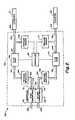
- an implantable infusion device 100in accordance with one embodiment of a present invention includes a reservoir 119 having an interior partition 120 forming first and second compartments 122 and 124 which can store different first and second medications.
- Compartments 122 and 124include respective fill ports 126 and 128, which open through the device shell 102 and through which medications can be supplied to fill the compartments.
- the compartments 122 and 124are also respectively provided with discharge ports 131 and 133, which are coupled to respective fluid transfer paths 144 and 160.
- the fluid transfer paths 144 and 160include the inlets 143 and 158 of fluid pumps 140 and 142.
- the fluid pumps 140 and 142also include outlets 147 and 164 that are adapted to communicate through the device shell 102 with respective catheters C1 and C2 for delivering the first and second medications to the same or different body sites.
- the exemplary fluid transfer paths 144 and 160also include respective pressure regulators 146 and 162 which prevent overpressurization in the reservoir from impacting the pumps or downstream fluid flow.
- Respective pressure sensors 152 and 170are also provided for monitoring pressure to, for example, detect catheter blockages or leaks.
- the fluid pumps 140 and 142are controlled by a controller 80 to produce independent medication flows from outlets 150 and 168 via fluid passageways 148 and 166, where each such flow conforms to a stored delivery profile accessed by the controller.
- FIGs 3 and 4Aschematically depict a structural configuration of an exemplary implantable infusion device 100, shown in block diagram form in Figure 2 , that can produce first and second independently controllable medication outflows.
- the device 100includes a housing or shell 102 with a cup shaped lower member 104 and a detachable cup shaped upper, or cover, member 106.
- the housing upper member 106is shown with a dashed line in Figure 4A and is omitted from Figure 3 for the sake of clarity.
- the housing lower and upper members 104 and 106are configured to mate with one another to enclose a volume 108 for accommodating the components depicted in Figure 2 together with a battery 109 or other suitable power source.
- the exemplary housing 102which is sized for implantation into a human body, will typically be about 2.54 to 7.62 cm (1 to 3 inches) long and about 2.54 to 7.62 cm (1 to 3 inches) wide (or 2.54 to 7.62 cm (1 to 3 inches) in diameter) and less than about 3.81 cm (1.5 inches) thick.
- the lower housing member 104 in the exemplary implantable infusion device 100includes an outer wall 110 with a stiff axially extending ring portion 112 and a cross wall portion 114 extending laterally across the bottom edge of the ring portion.
- the top edge of the ring portion 112supports, and is closed by, a mounting board 116, e.g., a circuit board.
- the housing member 104defines a closed sealed volume 118 between the lower surface of mounting board 116 and the interior surface of the lower housing cross wall portion 114.
- the sealed volume 118contains an interior partition 120 between a first reservoir compartment 122 and a second reservoir compartment 124. These compartments are intended to be suitably sealed so that they can respectively accommodate and isolate different first and second medications and/or different concentrations of the same medication, as discussed in greater detail below.
- first and second fill ports 126 and 128are supported on the mounting board 116.
- Each fill portincludes a self healing septum 130 which is accessible through cover portion 106 for piercing by a hypodermic needle.
- the first fill port 126communicates via passageway 132 with the first reservoir compartment 122.
- the second fill port 128communicates via passageway 134 with the second reservoir compartment 124.
- first and second fluid transfer devicessuch as pump heads 140 and 142 with an electromagnetic actuator 141 mounted on the board 116 between the pump heads
- the fluid inlet 143 ( Figure 2 ) of pump head 140is coupled via a fluid passageway 144, which may include a pressure regulator 146, to the interior of the first compartment 122.
- the fluid outlet 147 ( Figure 2 ) of pump head 140is coupled via a fluid passageway 148 to a first device outlet port 150 adapted for coupling to a first catheter.
- the fluid passageway 148may include a pressure sensor 152.
- actuation of the pump head 140transfers fluid from reservoir compartment 122 past pressure regulator 146 and pressure sensor 152 to device outlet port 150.
- Port 150is preferably configured for coupling to catheter C1 for delivery to an internal body site.
- the fluid inlet 158(see Figure 2 ) of pump head 142 is coupled via a fluid passageway 160, which may include a pressure regulator 162, to the interior of the second reservoir compartment 124.
- the fluid outlet 164(see Figure 2 ) of pump head 142 is coupled via a fluid passageway 166 to a second device outlet port 168 adapted for coupling to a second catheter.
- the fluid passageway 166may include a pressure sensor 170. Actuation of the pump head 142 acts to transfer fluid from reservoir compartment 124 to device outlet port 168, through catheter C2, and to a body site.
- FIG. 3 and 4Aincludes pump heads 140 and 142, which enable fluid to be transferred from a reservoir compartment held at ambient or negative pressure
- other types of fluid transfer devicesmay be employed.
- the reservoir compartmentsare held at a positive pressure
- the fluid transfer devicescould comprise controlled valves.
- the prior artshows various types of infusion devices using positive pressure and negative pressure reservoirs for medication delivery.
- the positive and negative pressuresare typically produced by suitable propellants, such as biphasic propellants.
- a negatively biased ambient pressure reservoirof the type generally described in International Application WO 2005/002642, published 13 January 2005 , may be employed.
- the '642 applicationdescribes an infusion device in which a medication reservoir has a movable wall which is exposed to ambient pressure.
- the reservoiris configured with a bias device, such as a spring, for exerting a force to produce a resultant interior pressure which is always negative with respect to the ambient pressure.
- Such a negatively biased ambient pressureis achieved in the embodiment illustrated in Figures 3 and 4A by forming the lower housing cross wall portion 114 of a flexible spring material biased to bow outwardly.
- the outer surface of cross portion 114is exposed to a positive ambient pressure F A which acts in a direction tending to collapse the cross portion 114.
- the inherent spring bias force F B of the cross portion 114acts in a direction opposite to the ambient force F A to produce an interior pressure in compartment 124 equal to:
- P CF A - F B / Area
- the exemplary partition 120 illustrated in Figures 3 and 4Ais formed of a pressure transmissive material and, accordingly, is a pressure transmissive partition.
- the interior pressure in compartment 122will equal the interior pressure in compartment 124, which will be negative with respect to ambient pressure acting against the exterior surface of cross portion 114.
- the partition 120performs the function of equalizing the pressure within the compartments 122 and 124.
- the exemplary partition 120has a wavy bellows-like shape, or some other non-linear shape, that allows the partition to adjust in size in response to volumetric changes within the compartments 122 and 124 in such a manner that the pressure transmissive material is not itself substantially stretched.
- suitable pressure transmissive materialsinclude flexible impermeable polymeric films, i.e. flexible films that do not diffuse solutes or liquids.
- suitable pressure transmissive materialsinclude polyvinylidene film, polyvinylidene fluoride (PVDF) film, polyvinylidene chloride (PVDC) film, polytetrafluoroethylene film such as Teflon® film, high density polyethylene film, and fluoropolymer film such as Halar® film.
- the filmswill typically be about 0.051 mm (0.002 inch) thick, but the actual thickness will depend on the material employed and the intended application.
- FIG. 4BAn alternative reservoir configuration is illustrated in Figure 4B .
- the reservoirincludes three compartments.
- a first reservoir compartment 122is separated from a second reservoir compartment 124 by a first pressure transmissive partition 120
- a third reservoir compartment 125is separated from the second reservoir compartment 124 by a second pressure transmissive partition 121.
- the reservoircan be configured with still additional compartments to suit the intended application.
- the pressure sourcee.g., propellant or ambient pressure, can be associated with any one of the compartments.
- FIG. 1A block diagram illustrating an example of an implantable infusion device with a propellant based pressurization arrangement.
- the implantable infusion device 100'is substantially identical to the implantable infusion device 100 illustrated in Figures 3 and 4A and similar elements are represented by similar reference numerals.
- the lower member 104' of the shell 102'does not include the aforementioned flexible cross-wall portion.
- an reservoir enclosure 111 with titanium bellowsis positioned within the sealed volume 118, and a pressure transmissive partition 120 is positioned within the reservoir enclosure.
- the pressure transmissive partition 120divides the reservoir within the reservoir enclosure 111 into a first reservoir compartment 122 and a second compartment 124.
- the remainder of the sealed volume 118is occupied by propellant P, which may be used to exert positive or negative pressure on the reservoir enclosure 111.
- propellant Pwhich may be used to exert positive or negative pressure on the reservoir enclosure 111.
- the pressure within the first and second compartments 122 and 124will be equalized by the pressure transmissive partition 120.
- an exemplary pump head 180has a fluid intake (rest) position and a fluid discharge (actuated) position.
- the pump head 180may, for example, be used as the pump head 140 and/or the pump head 142 described above with reference to Figures 3 and '4.
- the pump head 180may be actuated by a variety of different actuators.
- One such actuatoris the common actuator 250, which is discussed in detail below with reference to Figure 7 and includes the hammer 220 illustrated in Figures 5 and 6 .
- each pump headmay be paired with its own individual actuator, if desired.
- the exemplary pump head 180includes a block 182 defining a bore 183 extending inwardly from block end face 184.
- the bore 183includes an inlet chamber 185 leading into a piston channel 186.
- a fluid intake port 187opens into piston channel 186 from a passageway 190 coupled to a fluid source, e.g., reservoir compartment 122.
- Channel 186is configured to open into a reduced channel outlet port 192.
- a piston 194is mounted in channel 186 for reciprocal linear movement, i.e. from the quiescent intake (rest) position illustrated in Figure 5 to the actuated discharge position illustrated in Figure 6 , and back to the intake (rest) position.
- the clearance space 195 between the piston 194 and the piston channel 186should be minimized to insure efficient and consistent fluid volume discharge per stroke.
- the piston 194has a strike end 198 (at the right as viewed in Figure 5 ) and a pressure end or face 200 (at the left).
- the strike end 198 in the illustrated embodimentincludes a reduced diameter strike pin portion 202 extending from a greater diameter energy transfer portion 203.
- the portions 202 and 203are retained by a spring diaphragm 210 which seals the bore 183.
- the piston 194has a flange 204 carrying a ball portion 205 aligned with energy transfer portion 203.
- a return spring 208bears against the left face of flange 204 urging it to the right to engage portions 203 and 205.
- the spring diaphragm 210assists in centering the piston body 206 in channel 186 and establishing the quiescent intake (rest) position of the piston 194.
- a pump chamber 213is defined between the piston pressure face 200 and the channel outlet port 192.
- An elastomeric check valve element 212normally urged closed by spring 214, is mounted between channel outlet port 192 and the pump head outlet 216.
- the pump chamber volumeis approximately 0.25 microliters.
- piston pressure face 200moves approximately 0.20 millimeters within approximately 2 milliseconds or less to force a fluid volume (stroke volume) of approximately 0.25 microliters out through port 192 to the pump head outlet 216.
- stroke volumefluid volume
- the gap 231can be adjusted by including a stroke adjustment shim 222 which can be variably positioned along the portion 202 for engaging stop surface 224.
- the pump head 180is initially in the quiescent intake (rest) position depicted in Figure 5 .
- fluid from the reservoir compartment 122fills passageway 190 and, via port 187, the bore 183 including inlet chamber 185, the clearance space 195 surrounding piston 194, and the pump chamber 213.
- the pump head 180is actuated such that hammer 220 drives piston 194 from the position illustrated in Figure 5 to the position illustrated in Figure 6 , the pressure face 200 forces pump chamber fluid through channel outlet port 192 and past valve element 212 to pump head outlet 216.
- the clearance space 195is minimized (e.g., approximately 5.0 microns or less) so that most of the fluid in the pump chamber 213 is forced out through outlet port 192 with only a small portion moving back though the clearance space 195 to passageway 190 and the reservoir compartment 122.
- the axial hammer force required to actuate the pump headi.e. to move the piston 194 from the position illustrated in Figure 5 to the position illustrated in Figure 6 , must transfer sufficient energy to:
- the axial force applied to strike pin 202 to actuate the pump head 180can be produced by various mechanisms.
- One example of a such a mechanismis a common actuator 250 illustrated in Figure 7 .
- the common actuator 250which includes the aforementioned hammer 220, may be used to actuate a pair of pump heads 180.
- a "common actuator”is a single device that can be associated with a plurality of pump heads or other fluid transfer devices and actuated in more than one actuation mode to independently drive (or not drive) each of the fluid transfer devices. More specifically, a common actuator that is used in combination with a first and second fluid transfer devices may have a first actuation mode that actuates the first fluid transfer device to discharge fluid while the second fluid transfer device remains unactuated, a second actuation mode that causes the second fluid transfer device to discharge fluid while the first fluid transfer device remains unactuated, and a neutral mode.
- neutral modedescribes a state where common actuator (or a portion of the common actuator) is in a position or condition that results in both fluid transfer devices remaining unactuated.
- a common actuator that is used in combination with first and second pump headsmay have a first actuation mode that drives the first pump head to discharge fluid while the second pump head remains in the intake position, a second actuation mode that drives the second pump head to discharge fluid while the first pump head remains in the intake position, and a neutral mode that allows both pump heads to remain in their respective intake positions.
- An actuation cycleoccurs when the common actuator transitions from the neutral mode to the first (or second) actuation mode and back to the neutral mode.
- the common actuatormay remain in the neutral mode at the end of the actuation cycle for a predetermined period before beginning the next actuation cycle. Alternatively, at the end of an action cycle, the common actuator will immediately begin the next actuation cycle.
- a common actuatormay be used to drive different pump heads (or other fluid transfer devices) at the same rate or at different rates. With respect to driving the pump heads at the same rate, this may be accomplished by simply alternating between the first and second modes, with or without pauses in the neutral mode between each actuation cycle or between some combination of actuation cycles. Different pump head driving rates may be accomplished by actuating one pump head more frequently than the other.
- the common actuatorcould be operated such that the first actuation mode occurs twice for each occurrence of the second actuation mode.
- Another exemplary actuation regimenis useful in those instances where one medication is dispensed at a regular interval (or constant rate) and another medication is dispensed at a variable rate, e.g. in response to a predetermined bodily condition or patient request.
- the common actuatorcould be actuated in the first actuation mode at the regular interval and only actuated in the second actuation mode in response to the predetermined bodily condition or patient request.
- common actuator 250one example of a common actuator that may be used to actuate first and second pump heads 180a and 180b, which are identical to pump head 180 and shown here in simplified form, is the common actuator 250.
- the hammer 220In the first actuation mode, the hammer 220 is linearly driven in a first direction to actuate the first pump head 180a and, in the second actuation mode, the hammer is linearly driven in a second direction to actuate the second pump head 180b.
- the second pump head 180bwill remain in the intake position during the first actuation mode, while the first pump head 180b will remain in the intake position during the second actuation mode.
- the common actuator 250also has a neutral mode, where neither of the pump heads 180a and 180b are actuated.
- the common actuator 250is shown in the neutral mode in Figure 7 .
- the hammer 220 in the illustrated embodimentis a rod of magnetic material (i.e. an armature) that is suspended by spring mounts 232.
- the hammer 220also extends axially through a fixedly positioned coil winding 234.
- currentis driven through the coil winding 234 in one direction and the resulting electromagnetic force propels the hammer 220 in the first direction against the strike pin 202 of pump head 180a.
- the spring mounts 232will return the hammer 220 to the neutral position when current flow ends (e.g. about 20-100 milliseconds after it begins in some embodiments), thereby completing the actuation cycle.
- Currentis driven through the coil winding 234 in the opposite direction in the second actuation mode.
- the resulting electromagnetic forcepropels the hammer 220 in the second direction against the strike pin 202 of pump head 180b.
- the spring mounts 232will return the hammer 220 to the neutral position when current flow ends.
- the current driven through the coil winding 234may be controlled by a suitable controller such as, for example, the controller 44 ( Figure 1 ) or the controller 80 ( Figure 2 ).
- the common actuator illustrated in Figure 7is merely one example of a common actuator that may be used to selectively drive two or more fluid transfer devices.
- a moving coil actuatorHere, a magnet is held in a fixed position and a coil moves relative thereto. A hammer is carried by the coil, or individual hammers may be carried at opposite ends of the coil, for movement with the coil.
- the common actuator 250'(which is otherwise identical to actuator 250), includes resilient membranes 233 (only one shown in Figures 8 and 9 ) or other resilient devices that are positioned over the longitudinal ends of the hammer 220.
- the resilient membranes 233perform the same functions as the spring mounts 232. More specifically, when the current induced electromagnetic force that drives the hammer 220 from the position illustrated in Figure 8 to the strike position illustrated in Figure 9 , and stretches the membrane 233 is removed, the membrane will drive the hammer back to the position illustrated in Figure 8 .
- FIG. 252Another exemplary common actuator that may be used to selectively actuate first and second fluid transfer devices is generally represented by reference numeral 252 in Figure 10 .
- the actuator 252which is in its neutral mode orientation in Figure 10 , includes first and second piezoceramic disks 254 and 256 that are carried by a flexible diaphragm 258.
- the piezoceramic disks 254 and 256carry hammers 260 and 262.
- a voltageis applied across the piezoceramic disk 254, thereby causing the disk to bend in the first direction (i.e. to the left in Figure 10 ).
- the hammer 260will, in turn, strike the strike pin 202 of the pump head 180a and drive the associated piston to the discharge position.
- the piezoceramic disk 254, as well the remainder of the common actuator 252,will return to the neutral mode illustrated in Figure 10 when the voltage is removed.
- a voltageis applied across the piezoceramic disk 256, thereby causing the a disk to bend in the second direction (i.e. to the right in Figure 10 ).
- the hammer 262will, in turn, strike the strike pin 202 of the pump head 180b and drive the associated piston to the discharge position.
- piezo-type common actuatorsmay also be employed.
- a single piezoceramic disk that bends in opposite directions based on the polarity of the applied voltage, and has unbent neutral statemay be carried on the flexible diaphragm 258 in place of the disks illustrated in Figure 10 .
- Cantilevered piezo elementswhich are another alternative, eliminate the need for the flexible diaphragm.
- the hammer(s)may be eliminated so that a piezoceramic element strikes the strike pin 202 or the corresponding portion of some other fluid transfer device.
- Piezo-type common actuatorsmay also be employed in those instances where the fluid transfer devices are microelectromechanical system (MEMS) based pumps or valves.
- MEMSmicroelectromechanical system
- Common actuators that may be used to selectively actuate a plurality of fluid transfer devicesare not limited to those which move linearly back and forth.
- rotary cam actuatorsthat have, for example, left, right and neutral positions may be employed.
- An actuator that relies on the heat triggered expansion of a gas, such as air,may also be used as common actuator for selectively actuating two or more fluid transfer devices.
Landscapes
- Health & Medical Sciences (AREA)
- Vascular Medicine (AREA)
- Engineering & Computer Science (AREA)
- Anesthesiology (AREA)
- Biomedical Technology (AREA)
- Heart & Thoracic Surgery (AREA)
- Hematology (AREA)
- Life Sciences & Earth Sciences (AREA)
- Animal Behavior & Ethology (AREA)
- General Health & Medical Sciences (AREA)
- Public Health (AREA)
- Veterinary Medicine (AREA)
- Infusion, Injection, And Reservoir Apparatuses (AREA)
- External Artificial Organs (AREA)
Abstract
Description
- The present inventions relate generally to implantable infusion devices.
- Implantable infusion devices typically include a housing containing a medication reservoir which can be filled transcutaneously by a hypodermic needle penetrating a fill port septum. The medication reservoir is generally coupled via an internal flow path to a device outlet port for delivering medication through a catheter to a patient body site. Typical infusion devices also include a controller and a fluid transfer mechanism, such as a pump or a valve, for moving the medication from the reservoir through the internal flow path to the device's outlet port. The use of such implantable infusion devices has been well established in pain management, and therapies such as diabetes control, where a single medication is delivered to a single body site.
- In other therapies, it is desirable to deliver the same medication to two different body sites, such as cisplatinum to the ovaries for ovarian cancer, either at the same rate or at different rates. In yet other therapies, there is a need to deliver two or more distinct medications to different body sites or to the same site independently. For example, with some pain management protocols, it is desirable to deliver morphine and clonidine to a patient's intrathecal site. In certain cancer therapies, it may be desirable to deliver multiple medications to multiple sites. As a further example, in diabetes therapy, insulin and glucogon may be administered sequentially to lower or to raise blood sugar respectively.
US 2002/156462 A1 discloses a programmable implantable pump with accessory reservoirs, a patient controller, and a multiple independent lumen catheter.US 2002/188327 A1 discloses drug delivery for treatment of cardiac arrhythmia with automatic administration of anti-arrhythmia drugs infused into a patient's body by an implantable drug delivery system.US 3 923 060 A discloses an apparatus for dispensing drugs and other medications within a patient's body, which apparatus is adapted to be entirely implanted and to dispense such substances via a self-powered dispensing device over a long period of time, e.g., one to several years, in accordance with the actual needs of the patient.- The present inventions provide an implantable infusion device having the technical features as described in the independent claim. Preferred embodiments of the present inventions are described in the dependent claims.
- The implantable infusion device in accordance with the present invention includes multiple fluid transfer devices that are actuated by a common actuator. Such a device is particularly advantageous because it greatly reduces the amount of space within the device that must be dedicated to the actuation of the fluid transfer devices.
Figure 1A is a block diagram of an implantable infusion device in accordance with one embodiment of a present invention.Figure 1B is a block diagram of an implantable infusion device in accordance with one embodiment of a present invention.Figure 2 is a block diagram of an implantable infusion device in accordance with one embodiment of a present invention.Figure 3 is a schematic plan view of an implantable infusion device in accordance with one embodiment of a present invention.Figure 4A is a schematic sectional view taken substantially alongplane 4A-4A inFigure 3 .Figure 4B is a schematic sectional view similar toFigure 4A with an alternate reservoir configuration.Figure 4C is a schematic partial sectional view similar toFigure 4A with an another alternate reservoir configuration.Figure 5 is a schematic diagram of a pump head in accordance one embodiment of a present invention in a fluid intake position.Figure 6 is a schematic diagram of a pump head in accordance one embodiment of a present invention in a discharge position.Figure 7 is a schematic diagram of a pair of fluid transfer devices with a common actuator in accordance one embodiment of a present invention.Figure 8 is a schematic diagram of a portion of a common actuator in accordance one embodiment of a present invention.Figure 9 is a schematic diagram of a portion of the common actuator illustrated inFigure 8 in an actuation mode.Figure 10 is a schematic side view of a portion of an infusion device in accordance with one embodiment of a present invention.- As illustrated for example in
Figure 1A , animplantable infusion device 20 in accordance with one embodiment of a present invention includes anouter shell 22 enveloping aninterior volume 24. Afluid reservoir 26, which is defined within theinternal volume 24, has afill port 28 opening through theouter shell 22. Fluid medication is supplied through the fill port 28 (e.g., via a hypodermic needle) to thereservoir 26 for storage. Thefluid reservoir 26 in the illustrated embodiment supplies two separate fluid transfer devices. More specifically, thefluid reservoir 26 includes adischarge port 30 that is coupled to a firstfluid transfer path 31 including a firstfluid transfer device 32. Thedischarge port 30 is also coupled to a secondfluid transfer path 34 including a secondfluid transfer device 35. The firstfluid transfer device 32 defines aninlet 36 and anoutlet 37. Similarly, the secondfluid transfer device 35 defines aninlet 38 and anoutlet 39. Theoutlets outer shell 22 and are adapted to communicate with respective catheters for delivering medication from thereservoir 26 to the same or different body sites. - The exemplary
fluid transfer devices common controller 44, such as a microprocessor, in accordance with different stored medication profiles, or protocols, that are accessible by the common controller. Each such profile can, for example, define delivery start times, delivery durations, delivery rates and other parameters. Thus, the independent operation of two or more fluid transfer devices allows the implantable infusion device 20 (as well as those discussed below) to, for example, deliver a single medication under different protocols to a single body site, deliver a single medication to multiple body sites, deliver multiple medications to multiple body sites, deliver multiple medications to a single body site, simultaneously deliver multiple medications at different rates, and/or deliver one medication at a constant rate and another medication at a variable rate, typically in accordance with a stored profile. Thefluid transfer paths Figure 2 . - As illustrated for example in
Figure 1B , animplantable infusion device 50 in accordance with one embodiment of a present invention includes areservoir 52 having aninterior partition 54 forming first andsecond compartments Compartments respective fill ports device shell 63, and through which medications can be supplied to fill the compartments. Thecompartments discharge ports fluid transfer paths fluid transfer paths inlets fluid transfer devices 72 and 74. Thefluid transfer devices 72 and 74 also includeoutlets 76 and 78 that are adapted to communicate through thedevice shell 63 with respective catheters for delivering the first and second medications to the same or different body sites. As is discussed below with reference toFigure 2 , thefluid transfer paths fluid transfer devices 72 and 74 are controlled by acontroller 80 to produce independent medication flows fromoutlets 76 and 78, where each such flow conforms to a stored delivery profile accessed by the controller. - One example of a suitable fluid transfer device is a pump mechanism with a fluid chamber and a pump element mounted for movement between an intake position for drawing fluid from the reservoir into the fluid chamber, and a discharge position for discharging fluid from the chamber to an outlet. The pump element can, for example, comprise a piston mounted for movement by a controlled actuator. Examples of piston-based pumps are discussed below. It should be noted, however, that piston-based pumps in accordance with the present inventions are not limited to such examples, and that embodiments of the inventions may include pumps that are not piston-based.
- Turning to
Figure 2 , animplantable infusion device 100 in accordance with one embodiment of a present invention includes areservoir 119 having aninterior partition 120 forming first andsecond compartments Compartments respective fill ports device shell 102 and through which medications can be supplied to fill the compartments. Thecompartments discharge ports 131 and 133, which are coupled to respectivefluid transfer paths fluid transfer paths inlets fluid pumps fluid pumps outlets device shell 102 with respective catheters C1 and C2 for delivering the first and second medications to the same or different body sites. The exemplaryfluid transfer paths respective pressure regulators Respective pressure sensors controller 80 to produce independent medication flows fromoutlets fluid passageways Figures 3 and 4A schematically depict a structural configuration of an exemplaryimplantable infusion device 100, shown in block diagram form inFigure 2 , that can produce first and second independently controllable medication outflows. Thedevice 100 includes a housing or shell 102 with a cup shapedlower member 104 and a detachable cup shaped upper, or cover,member 106. The housingupper member 106 is shown with a dashed line inFigure 4A and is omitted fromFigure 3 for the sake of clarity. The housing lower andupper members volume 108 for accommodating the components depicted inFigure 2 together with abattery 109 or other suitable power source. Theexemplary housing 102, which is sized for implantation into a human body, will typically be about 2.54 to 7.62 cm (1 to 3 inches) long and about 2.54 to 7.62 cm (1 to 3 inches) wide (or 2.54 to 7.62 cm (1 to 3 inches) in diameter) and less than about 3.81 cm (1.5 inches) thick.- The
lower housing member 104 in the exemplaryimplantable infusion device 100 includes anouter wall 110 with a stiff axially extendingring portion 112 and across wall portion 114 extending laterally across the bottom edge of the ring portion. The top edge of thering portion 112 supports, and is closed by, a mountingboard 116, e.g., a circuit board. Thus thehousing member 104 defines a closed sealedvolume 118 between the lower surface of mountingboard 116 and the interior surface of the lower housingcross wall portion 114. - The sealed
volume 118 contains aninterior partition 120 between afirst reservoir compartment 122 and asecond reservoir compartment 124. These compartments are intended to be suitably sealed so that they can respectively accommodate and isolate different first and second medications and/or different concentrations of the same medication, as discussed in greater detail below. - In the exemplary embodiment illustrated in
Figures 3 and 4A , first andsecond fill ports board 116. Each fill port includes a self healing septum 130 which is accessible throughcover portion 106 for piercing by a hypodermic needle. Thefirst fill port 126 communicates viapassageway 132 with thefirst reservoir compartment 122.
Similarly, thesecond fill port 128 communicates viapassageway 134 with thesecond reservoir compartment 124. - As illustrated for example in
Figure 3 , first and second fluid transfer devices, such as pump heads 140 and 142 with anelectromagnetic actuator 141 mounted on theboard 116 between the pump heads, may be provided. In the illustrated embodiment, the fluid inlet 143 (Figure 2 ) ofpump head 140 is coupled via afluid passageway 144, which may include apressure regulator 146, to the interior of thefirst compartment 122. The fluid outlet 147 (Figure 2 ) ofpump head 140 is coupled via afluid passageway 148 to a firstdevice outlet port 150 adapted for coupling to a first catheter. Thefluid passageway 148 may include apressure sensor 152. In operation, actuation of thepump head 140 transfers fluid fromreservoir compartment 122past pressure regulator 146 andpressure sensor 152 todevice outlet port 150.Port 150 is preferably configured for coupling to catheter C1 for delivery to an internal body site. - Similarly, the fluid inlet 158 (see
Figure 2 ) ofpump head 142 is coupled via afluid passageway 160, which may include apressure regulator 162, to the interior of thesecond reservoir compartment 124. The fluid outlet 164 (seeFigure 2 ) ofpump head 142 is coupled via afluid passageway 166 to a seconddevice outlet port 168 adapted for coupling to a second catheter. Thefluid passageway 166 may include apressure sensor 170. Actuation of thepump head 142 acts to transfer fluid fromreservoir compartment 124 todevice outlet port 168, through catheter C2, and to a body site. - Although the embodiment illustrated in
Figures 3 and 4A includes pump heads 140 and 142, which enable fluid to be transferred from a reservoir compartment held at ambient or negative pressure, other types of fluid transfer devices may be employed. For example, if the reservoir compartments are held at a positive pressure, then the fluid transfer devices could comprise controlled valves. The prior art shows various types of infusion devices using positive pressure and negative pressure reservoirs for medication delivery. The positive and negative pressures are typically produced by suitable propellants, such as biphasic propellants. - In one exemplary embodiment, a negatively biased ambient pressure reservoir of the type generally described in International Application
WO 2005/002642, published 13 January 2005 , may be employed. The '642 application describes an infusion device in which a medication reservoir has a movable wall which is exposed to ambient pressure. The reservoir is configured with a bias device, such as a spring, for exerting a force to produce a resultant interior pressure which is always negative with respect to the ambient pressure. - Such a negatively biased ambient pressure is achieved in the embodiment illustrated in
Figures 3 and 4A by forming the lower housingcross wall portion 114 of a flexible spring material biased to bow outwardly. The outer surface ofcross portion 114 is exposed to a positive ambient pressure FA which acts in a direction tending to collapse thecross portion 114. The inherent spring bias force FB of thecross portion 114 acts in a direction opposite to the ambient force FA to produce an interior pressure incompartment 124 equal to:
- The
exemplary partition 120 illustrated inFigures 3 and 4A is formed of a pressure transmissive material and, accordingly, is a pressure transmissive partition. As a consequence, the interior pressure incompartment 122 will equal the interior pressure incompartment 124, which will be negative with respect to ambient pressure acting against the exterior surface ofcross portion 114. In other words, thepartition 120 performs the function of equalizing the pressure within thecompartments exemplary partition 120 has a wavy bellows-like shape, or some other non-linear shape, that allows the partition to adjust in size in response to volumetric changes within thecompartments - With respect to materials, examples of suitable pressure transmissive materials include flexible impermeable polymeric films, i.e. flexible films that do not diffuse solutes or liquids. Specific examples include polyvinylidene film, polyvinylidene fluoride (PVDF) film, polyvinylidene chloride (PVDC) film, polytetrafluoroethylene film such as Teflon® film, high density polyethylene film, and fluoropolymer film such as Halar® film. The films will typically be about 0.051 mm (0.002 inch) thick, but the actual thickness will depend on the material employed and the intended application.
- An alternative reservoir configuration is illustrated in
Figure 4B . Here, the reservoir includes three compartments. Afirst reservoir compartment 122 is separated from asecond reservoir compartment 124 by a firstpressure transmissive partition 120, and athird reservoir compartment 125 is separated from thesecond reservoir compartment 124 by a secondpressure transmissive partition 121. It should be appreciated that the reservoir can be configured with still additional compartments to suit the intended application. Moreover, it should be understood that since the multiple compartments are exposed to the same pressure, the pressure source, e.g., propellant or ambient pressure, can be associated with any one of the compartments. - As noted above, positive and negative reservoir pressures may be produced by a suitable propellant. One example of an implantable infusion device with a propellant based pressurization arrangement is generally represented by reference numeral 100' in
Figure 4C . The implantable infusion device 100' is substantially identical to theimplantable infusion device 100 illustrated inFigures 3 and 4A and similar elements are represented by similar reference numerals. Here, however, the lower member 104' of the shell 102' does not include the aforementioned flexible cross-wall portion. Instead, anreservoir enclosure 111 with titanium bellows is positioned within the sealedvolume 118, and apressure transmissive partition 120 is positioned within the reservoir enclosure. Thepressure transmissive partition 120 divides the reservoir within thereservoir enclosure 111 into afirst reservoir compartment 122 and asecond compartment 124. The remainder of the sealedvolume 118 is occupied by propellant P, which may be used to exert positive or negative pressure on thereservoir enclosure 111. Here too, the pressure within the first andsecond compartments pressure transmissive partition 120. - Turning to
Figures 5 and 6 , anexemplary pump head 180 has a fluid intake (rest) position and a fluid discharge (actuated) position. Thepump head 180 may, for example, be used as thepump head 140 and/or thepump head 142 described above with reference toFigures 3 and '4. Thepump head 180 may be actuated by a variety of different actuators. One such actuator is thecommon actuator 250, which is discussed in detail below with reference toFigure 7 and includes thehammer 220 illustrated inFigures 5 and 6 . Alternatively, in those instances where two or more pump heads are employed, each pump head may be paired with its own individual actuator, if desired. - The
exemplary pump head 180 includes ablock 182 defining abore 183 extending inwardly fromblock end face 184. Thebore 183 includes aninlet chamber 185 leading into apiston channel 186. Afluid intake port 187 opens intopiston channel 186 from apassageway 190 coupled to a fluid source, e.g.,reservoir compartment 122.Channel 186 is configured to open into a reducedchannel outlet port 192. Apiston 194 is mounted inchannel 186 for reciprocal linear movement, i.e. from the quiescent intake (rest) position illustrated inFigure 5 to the actuated discharge position illustrated inFigure 6 , and back to the intake (rest) position. Theclearance space 195 between thepiston 194 and thepiston channel 186 should be minimized to insure efficient and consistent fluid volume discharge per stroke. Thepiston 194 has a strike end 198 (at the right as viewed inFigure 5 ) and a pressure end or face 200 (at the left). Thestrike end 198 in the illustrated embodiment includes a reduced diameterstrike pin portion 202 extending from a greater diameterenergy transfer portion 203. Theportions spring diaphragm 210 which seals thebore 183. Thepiston 194 has aflange 204 carrying aball portion 205 aligned withenergy transfer portion 203. Areturn spring 208 bears against the left face offlange 204 urging it to the right to engageportions spring diaphragm 210 assists in centering thepiston body 206 inchannel 186 and establishing the quiescent intake (rest) position of thepiston 194. - A
pump chamber 213 is defined between thepiston pressure face 200 and thechannel outlet port 192. An elastomericcheck valve element 212, normally urged closed byspring 214, is mounted betweenchannel outlet port 192 and thepump head outlet 216. - In one exemplary implementation of the
pump head 180, the pump chamber volume is approximately 0.25 microliters. When actuated by thehammer 220 axially striking thefree end 217 of thestrike pin portion 202,piston pressure face 200 moves approximately 0.20 millimeters within approximately 2 milliseconds or less to force a fluid volume (stroke volume) of approximately 0.25 microliters out throughport 192 to thepump head outlet 216. To optimize the transfer of energy fromhammer 220 to pinportion 202, it is preferable to provide asmall gap 231 between thehammer 220 and thestrike pin portion 202 to build up kinetic energy. Thegap 231 can be adjusted by including astroke adjustment shim 222 which can be variably positioned along theportion 202 for engagingstop surface 224. - More particularly, assume that the
pump head 180 is initially in the quiescent intake (rest) position depicted inFigure 5 . In this position, fluid from thereservoir compartment 122 fillspassageway 190 and, viaport 187, thebore 183 includinginlet chamber 185, theclearance space 195 surroundingpiston 194, and thepump chamber 213. When thepump head 180 is actuated such thathammer 220 drivespiston 194 from the position illustrated inFigure 5 to the position illustrated inFigure 6 , thepressure face 200 forces pump chamber fluid throughchannel outlet port 192 andpast valve element 212 to pumphead outlet 216. Theclearance space 195 is minimized (e.g., approximately 5.0 microns or less) so that most of the fluid in thepump chamber 213 is forced out throughoutlet port 192 with only a small portion moving back though theclearance space 195 topassageway 190 and thereservoir compartment 122. - As should be appreciated, the axial hammer force required to actuate the pump head, i.e. to move the
piston 194 from the position illustrated inFigure 5 to the position illustrated inFigure 6 , must transfer sufficient energy to: - 1) Deflect
diaphragm 210, - 2)
Compress return spring 208, - 3)
Compress valve spring 214, and - 4) Overcome head pressure at the
pump head outlet 216 which can, for example, include some degree of occlusion in a downstream catheter. - The axial force applied to strike
pin 202 to actuate thepump head 180 can be produced by various mechanisms. One example of a such a mechanism is acommon actuator 250 illustrated inFigure 7 . Thecommon actuator 250, which includes theaforementioned hammer 220, may be used to actuate a pair of pump heads 180. - As used herein, a "common actuator" is a single device that can be associated with a plurality of pump heads or other fluid transfer devices and actuated in more than one actuation mode to independently drive (or not drive) each of the fluid transfer devices. More specifically, a common actuator that is used in combination with a first and second fluid transfer devices may have a first actuation mode that actuates the first fluid transfer device to discharge fluid while the second fluid transfer device remains unactuated, a second actuation mode that causes the second fluid transfer device to discharge fluid while the first fluid transfer device remains unactuated, and a neutral mode. The term "neutral mode" describes a state where common actuator (or a portion of the common actuator) is in a position or condition that results in both fluid transfer devices remaining unactuated. In the exemplary context of the pump heads, a common actuator that is used in combination with first and second pump heads may have a first actuation mode that drives the first pump head to discharge fluid while the second pump head remains in the intake position, a second actuation mode that drives the second pump head to discharge fluid while the first pump head remains in the intake position, and a neutral mode that allows both pump heads to remain in their respective intake positions. An actuation cycle occurs when the common actuator transitions from the neutral mode to the first (or second) actuation mode and back to the neutral mode. Depending on the desired actuation rate, the common actuator may remain in the neutral mode at the end of the actuation cycle for a predetermined period before beginning the next actuation cycle. Alternatively, at the end of an action cycle, the common actuator will immediately begin the next actuation cycle.
- A common actuator may be used to drive different pump heads (or other fluid transfer devices) at the same rate or at different rates. With respect to driving the pump heads at the same rate, this may be accomplished by simply alternating between the first and second modes, with or without pauses in the neutral mode between each actuation cycle or between some combination of actuation cycles. Different pump head driving rates may be accomplished by actuating one pump head more frequently than the other. For example, the common actuator could be operated such that the first actuation mode occurs twice for each occurrence of the second actuation mode. Another exemplary actuation regimen is useful in those instances where one medication is dispensed at a regular interval (or constant rate) and another medication is dispensed at a variable rate, e.g. in response to a predetermined bodily condition or patient request. Here, the common actuator could be actuated in the first actuation mode at the regular interval and only actuated in the second actuation mode in response to the predetermined bodily condition or patient request.
- Referring again to
Figure 7 , and although common actuators are not so limited, one example of a common actuator that may be used to actuate first and second pump heads 180a and 180b, which are identical to pumphead 180 and shown here in simplified form, is thecommon actuator 250. In the first actuation mode, thehammer 220 is linearly driven in a first direction to actuate thefirst pump head 180a and, in the second actuation mode, the hammer is linearly driven in a second direction to actuate thesecond pump head 180b. Thesecond pump head 180b will remain in the intake position during the first actuation mode, while thefirst pump head 180b will remain in the intake position during the second actuation mode. Thecommon actuator 250 also has a neutral mode, where neither of the pump heads 180a and 180b are actuated. Thecommon actuator 250 is shown in the neutral mode inFigure 7 . - The
hammer 220 in the illustrated embodiment is a rod of magnetic material (i.e. an armature) that is suspended by spring mounts 232. Thehammer 220 also extends axially through a fixedly positioned coil winding 234. In the first actuation mode, current is driven through the coil winding 234 in one direction and the resulting electromagnetic force propels thehammer 220 in the first direction against thestrike pin 202 ofpump head 180a. The spring mounts 232 will return thehammer 220 to the neutral position when current flow ends (e.g. about 20-100 milliseconds after it begins in some embodiments), thereby completing the actuation cycle. Current is driven through the coil winding 234 in the opposite direction in the second actuation mode. The resulting electromagnetic force propels thehammer 220 in the second direction against thestrike pin 202 ofpump head 180b. Here too, the spring mounts 232 will return thehammer 220 to the neutral position when current flow ends. The current driven through the coil winding 234 may be controlled by a suitable controller such as, for example, the controller 44 (Figure 1 ) or the controller 80 (Figure 2 ). - The common actuator illustrated in
Figure 7 is merely one example of a common actuator that may be used to selectively drive two or more fluid transfer devices. With respect to those which employ electromagnetic force to selectively drive a hammer, one alternative is a moving coil actuator. Here, a magnet is held in a fixed position and a coil moves relative thereto. A hammer is carried by the coil, or individual hammers may be carried at opposite ends of the coil, for movement with the coil. Another alternative is illustrated inFigures 8 and 9 . Here, instead of the aforementioned spring mounts 232, the common actuator 250' (which is otherwise identical to actuator 250), includes resilient membranes 233 (only one shown inFigures 8 and 9 ) or other resilient devices that are positioned over the longitudinal ends of thehammer 220. Theresilient membranes 233 perform the same functions as the spring mounts 232. More specifically, when the current induced electromagnetic force that drives thehammer 220 from the position illustrated inFigure 8 to the strike position illustrated inFigure 9 , and stretches themembrane 233 is removed, the membrane will drive the hammer back to the position illustrated inFigure 8 . - Another exemplary common actuator that may be used to selectively actuate first and second fluid transfer devices is generally represented by
reference numeral 252 inFigure 10 . Although thecommon actuator 252 may be used in combination with a variety of fluid transfer devices, pump heads 180a and 180b are shown for purposes of illustration. Theactuator 252, which is in its neutral mode orientation inFigure 10 , includes first and secondpiezoceramic disks flexible diaphragm 258. Thepiezoceramic disks hammers piezoceramic disk 254, thereby causing the disk to bend in the first direction (i.e. to the left inFigure 10 ). Thehammer 260 will, in turn, strike thestrike pin 202 of thepump head 180a and drive the associated piston to the discharge position. Thepiezoceramic disk 254, as well the remainder of thecommon actuator 252, will return to the neutral mode illustrated inFigure 10 when the voltage is removed. Similarly, in the second actuation mode, a voltage is applied across thepiezoceramic disk 256, thereby causing the a disk to bend in the second direction (i.e. to the right inFigure 10 ). Thehammer 262 will, in turn, strike thestrike pin 202 of thepump head 180b and drive the associated piston to the discharge position. - Other piezo-type common actuators may also be employed. By way of example, a single piezoceramic disk that bends in opposite directions based on the polarity of the applied voltage, and has unbent neutral state, may be carried on the
flexible diaphragm 258 in place of the disks illustrated inFigure 10 . Cantilevered piezo elements, which are another alternative, eliminate the need for the flexible diaphragm. Additionally, in any piezo-type common actuator, the hammer(s) may be eliminated so that a piezoceramic element strikes thestrike pin 202 or the corresponding portion of some other fluid transfer device. Piezo-type common actuators may also be employed in those instances where the fluid transfer devices are microelectromechanical system (MEMS) based pumps or valves. - Common actuators that may be used to selectively actuate a plurality of fluid transfer devices are not limited to those which move linearly back and forth. For example, rotary cam actuators that have, for example, left, right and neutral positions may be employed. An actuator that relies on the heat triggered expansion of a gas, such as air, may also be used as common actuator for selectively actuating two or more fluid transfer devices.

Claims (14)
- An infusion device configured for implantation in a patient's body, the infusion device comprising:a housing (102, 102');a reservoir mounted (119) in the housing and configured to contain at least one fluid medication;a first fluid transfer device (140, 180a) mounted in the housing actuatable to transfer a first fluid flow from a first fluid inlet (143) coupled to the reservoir to a first fluid outlet;a second fluid transfer device (142, 180b) mounted in the housing actuatable to transfer a second fluid flow from a second fluid inlet (158) coupled to the reservoir to a second fluid outlet;a common actuator (141, 250, 250', 252) associated with the first and second fluid transfer devices such that the common actuator actuates the first fluid transfer device when in a first actuation mode, actuates the second fluid transfer device when in a second actuation mode, and does not actuate the first and second fluid transfer devices when in a neutral mode; anda controller (44) mounted in the housing that controls the common actuator.
- The infusion device of claim 1 wherein
the first fluid transfer device (140, 180a) includes a first fluid chamber (213) and a first pump element (194) mounted for movement between an intake position and a discharge position; and
the common actuator (141, 250, 250', 252) is configured to move the first pump element to the discharge position when in the first actuation mode. - The infusion device of claim 1 wherein
the first fluid transfer device (140, 180a) comprises a first fluid chamber (213) and a first piston (194) mounted for reciprocal linear movement between an intake position and a discharge position; and
the second fluid transfer device (140, 180a) comprises a second fluid chamber (213) and a second piston (194) mounted for reciprocal linear movement between an intake position and a discharge position. - The infusion device of claim 3 wherein the common actuator (141, 250, 250'. 252) is configured to move the first piston (194) to its discharge position when in the first actuation mode and is configured to move the second piston (194) to its discharge position when in the second actuation mode.
- The infusion device of claim 3 wherein the common actuator (141, 250, 250', 252) includes a linearly movable member (220, 260/262) that is configured to move in a first direction during the first actuation mode to move the first piston (194) to its discharge position and is configured to move in a second direction during the second actuation mode to move the second piston (194) to its discharge position.
- The infusion device of claim 3 wherein the common actuator (141, 250, 250') comprises an electrically powered actuator with an armature (220) that is driven in a first direction during the first actuation mode to move the first piston (194) to its discharge position and is driven in a second direction during the second actuation mode to move the second piston (194) to its discharge position.
- The infusion device of claim 1 wherein the controller (44) is adapted to operate the common actuator (141, 250, 250', 252) to actuate the first fluid transfer device (140, 180a) at a constant rate and actuate the second fluid transfer device (142, 180b) a variable rate.
- The infusion device of claim 1 wherein the controller (44) includes electronic circuitry for specifying first and second fluid flow delivery schedules and for controlling the common actuator (141, 250, 250', 252) in accordance with the first and second schedules.
- The infusion device of claim 1 wherein
the reservoir (119) includes at least first and second reservoir compartments (122 and 124);
the first fluid inlet (143) is coupled to the first reservoir compartment; and
the second fluid inlet (158) is coupled to the second reservoir compartment. - The infusion device of claim 1 or 9 wherein the first fluid transfer device comprises a pump mechanism.
- The infusion device of claim 1 or 9 wherein the first fluid transfer device includes a valve mechanism.
- The infusion device of claim 9 wherein the reservoir (119) includes a pressure transmissive interior partition (120) between the first and second reservoir compartments (122 and 124) configured to equalize pressure within the first and second reservoir compartments.
- The infusion device of claim 1 wherein the common actuator comprises an electrically powered actuator (141, 250, 250') with an armature (220) that is driven in a first direction during the first actuation mode and is driven in a second direction during the second actuation mode.
- The infusion device of claim 1 wherein the common actuator (252) comprises a piezo element that is configured to deflect in a first direction during the first actuation mode and is configured to deflect in a second direction during the second actuation mode.
Priority Applications (1)
| Application Number | Priority Date | Filing Date | Title |
|---|---|---|---|
| EP09152284AEP2050476B1 (en) | 2005-05-26 | 2006-05-26 | Implantable infusion device with multiple controllable fluid outlets |
Applications Claiming Priority (2)
| Application Number | Priority Date | Filing Date | Title |
|---|---|---|---|
| US68512605P | 2005-05-26 | 2005-05-26 | |
| PCT/US2006/020289WO2006127923A2 (en) | 2005-05-26 | 2006-05-26 | Implantable infusion device with multiple controllable fluid outlets |
Related Child Applications (1)
| Application Number | Title | Priority Date | Filing Date |
|---|---|---|---|
| EP09152284ADivisionEP2050476B1 (en) | 2005-05-26 | 2006-05-26 | Implantable infusion device with multiple controllable fluid outlets |
Publications (2)
| Publication Number | Publication Date |
|---|---|
| EP1888144A2 EP1888144A2 (en) | 2008-02-20 |
| EP1888144B1true EP1888144B1 (en) | 2009-12-09 |
Family
ID=37002696
Family Applications (2)
| Application Number | Title | Priority Date | Filing Date |
|---|---|---|---|
| EP06771202ACeasedEP1888144B1 (en) | 2005-05-26 | 2006-05-26 | Implantable infusion device with multiple controllable fluid outlets |
| EP09152284ACeasedEP2050476B1 (en) | 2005-05-26 | 2006-05-26 | Implantable infusion device with multiple controllable fluid outlets |
Family Applications After (1)
| Application Number | Title | Priority Date | Filing Date |
|---|---|---|---|
| EP09152284ACeasedEP2050476B1 (en) | 2005-05-26 | 2006-05-26 | Implantable infusion device with multiple controllable fluid outlets |
Country Status (5)
| Country | Link |
|---|---|
| US (2) | US8002747B2 (en) |
| EP (2) | EP1888144B1 (en) |
| AT (1) | ATE451132T1 (en) |
| DE (1) | DE602006011000D1 (en) |
| WO (1) | WO2006127923A2 (en) |
Families Citing this family (58)
| Publication number | Priority date | Publication date | Assignee | Title |
|---|---|---|---|---|
| ATE451132T1 (en) | 2005-05-26 | 2009-12-15 | Infusion Systems Llc | IMPLANTABLE INFUSION DEVICE WITH MULTIPLE CONTROLLED FLUID OUTLETS |
| WO2009086112A2 (en)† | 2007-12-20 | 2009-07-09 | University Of Southern California | Apparatus and methods for delivering therapeutic agents |
| US20090281494A1 (en)* | 2008-05-06 | 2009-11-12 | Das Stephen D | Heat Sterilizable Ambulatory Infusion Devices |
| US7959598B2 (en) | 2008-08-20 | 2011-06-14 | Asante Solutions, Inc. | Infusion pump systems and methods |
| US8480637B2 (en)* | 2008-11-14 | 2013-07-09 | The Board Of Regents Of The University Of Texas System | Nanochanneled device and related methods |
| US8721605B2 (en) | 2009-04-27 | 2014-05-13 | The Alfred E. Mann Foundation For Scientific Research | Implantable infusion devices with palpable landmarks and methods of needle detection |
| EP2724739B1 (en) | 2009-07-30 | 2015-07-01 | Tandem Diabetes Care, Inc. | Portable infusion pump system |
| US10143796B2 (en) | 2010-08-25 | 2018-12-04 | Medtronic, Inc. | Fluid delivery device refill access |
| US9737660B2 (en) | 2010-08-25 | 2017-08-22 | Medtronic, Inc. | Drug infusion device with controllable valve |
| US8979825B2 (en)* | 2011-04-15 | 2015-03-17 | Medtronic, Inc. | Implantable fluid delivery device including gas chamber pressure sensor |
| US8591456B2 (en)* | 2011-12-28 | 2013-11-26 | Palyon Medical (Bvi) Limited | Multiple reservoir programmable pump |
| US9180242B2 (en) | 2012-05-17 | 2015-11-10 | Tandem Diabetes Care, Inc. | Methods and devices for multiple fluid transfer |
| US9555186B2 (en) | 2012-06-05 | 2017-01-31 | Tandem Diabetes Care, Inc. | Infusion pump system with disposable cartridge having pressure venting and pressure feedback |
| US9173998B2 (en) | 2013-03-14 | 2015-11-03 | Tandem Diabetes Care, Inc. | System and method for detecting occlusions in an infusion pump |
| US9180243B2 (en) | 2013-03-15 | 2015-11-10 | Tandem Diabetes Care, Inc. | Detection of infusion pump conditions |
| US9421329B2 (en) | 2013-03-15 | 2016-08-23 | Tandem Diabetes Care, Inc. | Infusion device occlusion detection system |
| US9561324B2 (en) | 2013-07-19 | 2017-02-07 | Bigfoot Biomedical, Inc. | Infusion pump system and method |
| US9375537B2 (en)* | 2013-10-14 | 2016-06-28 | Medtronic Minimed, Inc. | Therapeutic agent injection device |
| GB2523989B (en) | 2014-01-30 | 2020-07-29 | Insulet Netherlands B V | Therapeutic product delivery system and method of pairing |
| JP2018505756A (en) | 2015-02-18 | 2018-03-01 | インシュレット コーポレイション | Fluid delivery and infusion device and method of use thereof |
| EP3374905A1 (en) | 2016-01-13 | 2018-09-19 | Bigfoot Biomedical, Inc. | User interface for diabetes management system |
| HK1256995A1 (en) | 2016-01-14 | 2019-10-11 | Bigfoot Biomedical, Inc. | Occlusion resolution in medication delivery devices, systems, and methods |
| US10806859B2 (en) | 2016-01-14 | 2020-10-20 | Bigfoot Biomedical, Inc. | Adjusting insulin delivery rates |
| US12383166B2 (en) | 2016-05-23 | 2025-08-12 | Insulet Corporation | Insulin delivery system and methods with risk-based set points |
| US10765807B2 (en)* | 2016-09-23 | 2020-09-08 | Insulet Corporation | Fluid delivery device with sensor |
| EP3500161A4 (en) | 2016-12-12 | 2020-01-08 | Bigfoot Biomedical, Inc. | ALARMS AND WARNINGS FOR MEDICINE DELIVERY DEVICES AND RELATED SYSTEMS AND METHODS |
| US10500334B2 (en) | 2017-01-13 | 2019-12-10 | Bigfoot Biomedical, Inc. | System and method for adjusting insulin delivery |
| US10881792B2 (en) | 2017-01-13 | 2021-01-05 | Bigfoot Biomedical, Inc. | System and method for adjusting insulin delivery |
| US10758675B2 (en) | 2017-01-13 | 2020-09-01 | Bigfoot Biomedical, Inc. | System and method for adjusting insulin delivery |
| EP3568859A1 (en) | 2017-01-13 | 2019-11-20 | Bigfoot Biomedical, Inc. | Insulin delivery methods, systems and devices |
| USD928199S1 (en) | 2018-04-02 | 2021-08-17 | Bigfoot Biomedical, Inc. | Medication delivery device with icons |
| EP4492399A3 (en) | 2018-05-04 | 2025-03-26 | Insulet Corporation | Safety constraints for a control algorithm-based drug delivery system |
| WO2020069406A1 (en) | 2018-09-28 | 2020-04-02 | Insulet Corporation | Activity mode for artificial pancreas system |
| US11565039B2 (en) | 2018-10-11 | 2023-01-31 | Insulet Corporation | Event detection for drug delivery system |
| USD920343S1 (en) | 2019-01-09 | 2021-05-25 | Bigfoot Biomedical, Inc. | Display screen or portion thereof with graphical user interface associated with insulin delivery |
| US11801344B2 (en) | 2019-09-13 | 2023-10-31 | Insulet Corporation | Blood glucose rate of change modulation of meal and correction insulin bolus quantity |
| US11935637B2 (en) | 2019-09-27 | 2024-03-19 | Insulet Corporation | Onboarding and total daily insulin adaptivity |
| EP4048365A1 (en) | 2019-10-23 | 2022-08-31 | The Alfred E. Mann Foundation for Scientific Research | Implantable infusion devices with closed loop sensing and associated methods |
| EP4354455A3 (en) | 2019-12-06 | 2024-07-10 | Insulet Corporation | Techniques and devices providing adaptivity and personalization in diabetes treatment |
| US11833329B2 (en) | 2019-12-20 | 2023-12-05 | Insulet Corporation | Techniques for improved automatic drug delivery performance using delivery tendencies from past delivery history and use patterns |
| AU2021206190A1 (en) | 2020-01-06 | 2022-08-18 | Insulet Corporation | Prediction of meal and/or exercise events based on persistent residuals |
| WO2021158580A1 (en) | 2020-02-03 | 2021-08-12 | Insulet Corporation | Use of fuzzy logic in predicting user behavior affecting blood glucose concentration |
| US11551802B2 (en) | 2020-02-11 | 2023-01-10 | Insulet Corporation | Early meal detection and calorie intake detection |
| US11986630B2 (en) | 2020-02-12 | 2024-05-21 | Insulet Corporation | Dual hormone delivery system for reducing impending hypoglycemia and/or hyperglycemia risk |
| US11547800B2 (en) | 2020-02-12 | 2023-01-10 | Insulet Corporation | User parameter dependent cost function for personalized reduction of hypoglycemia and/or hyperglycemia in a closed loop artificial pancreas system |
| US11324889B2 (en) | 2020-02-14 | 2022-05-10 | Insulet Corporation | Compensation for missing readings from a glucose monitor in an automated insulin delivery system |
| US11607493B2 (en) | 2020-04-06 | 2023-03-21 | Insulet Corporation | Initial total daily insulin setting for user onboarding |
| WO2022020197A1 (en) | 2020-07-22 | 2022-01-27 | Insulet Corporation | Open-loop insulin delivery basal parameters based on insulin delivery records |
| US11684716B2 (en) | 2020-07-31 | 2023-06-27 | Insulet Corporation | Techniques to reduce risk of occlusions in drug delivery systems |
| EP4221785A1 (en) | 2020-09-30 | 2023-08-09 | Insulet Corporation | Drug delivery device with integrated optical-based glucose monitor |
| WO2022072618A1 (en) | 2020-09-30 | 2022-04-07 | Insulet Corporation | Secure wireless communications between a glucose monitor and other devices |
| US11160925B1 (en) | 2021-01-29 | 2021-11-02 | Insulet Corporation | Automatic drug delivery system for delivery of a GLP-1 therapeutic |
| US11904140B2 (en) | 2021-03-10 | 2024-02-20 | Insulet Corporation | Adaptable asymmetric medicament cost component in a control system for medicament delivery |
| EP4305636A1 (en) | 2021-03-10 | 2024-01-17 | Insulet Corporation | A medicament delivery device with an adjustable and piecewise analyte level cost component to address persistent positive analyte level excursions |
| EP4101482A1 (en) | 2021-06-07 | 2022-12-14 | Insulet Corporation | Exercise safety prediction based on physiological conditions |
| US11738144B2 (en) | 2021-09-27 | 2023-08-29 | Insulet Corporation | Techniques enabling adaptation of parameters in aid systems by user input |
| US11439754B1 (en) | 2021-12-01 | 2022-09-13 | Insulet Corporation | Optimizing embedded formulations for drug delivery |
| US12097355B2 (en) | 2023-01-06 | 2024-09-24 | Insulet Corporation | Automatically or manually initiated meal bolus delivery with subsequent automatic safety constraint relaxation |
Family Cites Families (33)
| Publication number | Priority date | Publication date | Assignee | Title |
|---|---|---|---|---|
| US3126031A (en)* | 1964-03-24 | hayner | ||
| US3923060A (en)* | 1974-04-23 | 1975-12-02 | Jr Everett H Ellinwood | Apparatus and method for implanted self-powered medication dispensing having timing and evaluator means |
| US4003379A (en) | 1974-04-23 | 1977-01-18 | Ellinwood Jr Everett H | Apparatus and method for implanted self-powered medication dispensing |
| US4072146A (en) | 1976-09-08 | 1978-02-07 | Howes Randolph M | Venous catheter device |
| US4193397A (en)* | 1977-12-01 | 1980-03-18 | Metal Bellows Corporation | Infusion apparatus and method |
| US4373527B1 (en)* | 1979-04-27 | 1995-06-27 | Univ Johns Hopkins | Implantable programmable medication infusion system |
| US4449983A (en)* | 1982-03-22 | 1984-05-22 | Alza Corporation | Simultaneous delivery of two drugs from unit delivery device |
| US4443218A (en)* | 1982-09-09 | 1984-04-17 | Infusaid Corporation | Programmable implantable infusate pump |
| US4588394A (en)* | 1984-03-16 | 1986-05-13 | Pudenz-Schulte Medical Research Corp. | Infusion reservoir and pump system |
| US4634427A (en)* | 1984-09-04 | 1987-01-06 | American Hospital Supply Company | Implantable demand medication delivery assembly |
| CA1254091A (en) | 1984-09-28 | 1989-05-16 | Vladimir Feingold | Implantable medication infusion system |
| US4718893A (en)* | 1986-02-03 | 1988-01-12 | University Of Minnesota | Pressure regulated implantable infusion pump |
| US4894057A (en)* | 1987-06-19 | 1990-01-16 | Howes Randolph M | Flow enhanced multi-lumen venous catheter device |
| US5207642A (en)* | 1987-08-07 | 1993-05-04 | Baxter International Inc. | Closed multi-fluid delivery system and method |
| US5554117A (en)* | 1990-03-01 | 1996-09-10 | Michigan Transtech Corporation | Implantable access devices |
| US5240713A (en)* | 1991-09-27 | 1993-08-31 | Alza Corporation | Dual rate agent delivery device |
| US5718678A (en) | 1996-06-26 | 1998-02-17 | Medical Components, Inc. | Multi-lumen coaxial catheter and method for making same |
| US6796956B2 (en) | 1999-04-30 | 2004-09-28 | Medtronic, Inc. | Method and apparatus to control drug therapy dosages in an implantable pump |
| US6554822B1 (en) | 1999-04-30 | 2003-04-29 | University Of Southern California | Microbolus infusion pump |
| WO2000074751A1 (en)* | 1999-06-08 | 2000-12-14 | Medical Research Group, Inc. | Method and apparatus for infusing liquids using a chemical reaction in an implanted infusion device |
| US6436091B1 (en)* | 1999-11-16 | 2002-08-20 | Microsolutions, Inc. | Methods and implantable devices and systems for long term delivery of a pharmaceutical agent |
| FR2804031B1 (en)* | 2000-01-21 | 2002-10-18 | Taema | RESPIRATORY ANESTHESIA APPARATUS WITH PILOT DISCHARGE VALVE |
| US6471688B1 (en)* | 2000-02-15 | 2002-10-29 | Microsolutions, Inc. | Osmotic pump drug delivery systems and methods |
| US7083593B2 (en)* | 2001-04-18 | 2006-08-01 | Advanced Bionics Corporation | Programmable implantable pump with accessory reservoirs and multiple independent lumen catheter |
| US20020188327A1 (en)* | 2001-04-26 | 2002-12-12 | Chester Struble | Drug delivery for treatment of cardiac arrhythmia |
| US6997921B2 (en)* | 2001-09-07 | 2006-02-14 | Medtronic Minimed, Inc. | Infusion device and driving mechanism for same |
| US6652510B2 (en)* | 2001-09-07 | 2003-11-25 | Medtronic Minimed, Inc. | Implantable infusion device and reservoir for same |
| US6902544B2 (en)* | 2003-01-22 | 2005-06-07 | Codman & Shurtleff, Inc. | Troubleshooting accelerator system for implantable drug delivery pumps |
| EP1635894B1 (en) | 2003-06-25 | 2015-05-27 | Infusion Systems, LLC | Medication infusion device using negatively biased ambient pressure medication chamber |
| WO2005007223A2 (en)* | 2003-07-16 | 2005-01-27 | Sasha John | Programmable medical drug delivery systems and methods for delivery of multiple fluids and concentrations |
| US7896865B2 (en)* | 2003-09-30 | 2011-03-01 | Codman & Shurtleff, Inc. | Two-compartment reduced volume infusion pump |
| US8034030B2 (en)* | 2005-05-25 | 2011-10-11 | Palyon Medical (Bvi) Limited | Multi-reservoir implantable pump with variable flow rate capabilities |
| ATE451132T1 (en) | 2005-05-26 | 2009-12-15 | Infusion Systems Llc | IMPLANTABLE INFUSION DEVICE WITH MULTIPLE CONTROLLED FLUID OUTLETS |
- 2006
- 2006-05-26ATAT06771202Tpatent/ATE451132T1/ennot_activeIP Right Cessation
- 2006-05-26EPEP06771202Apatent/EP1888144B1/ennot_activeCeased
- 2006-05-26WOPCT/US2006/020289patent/WO2006127923A2/enactiveApplication Filing
- 2006-05-26EPEP09152284Apatent/EP2050476B1/ennot_activeCeased
- 2006-05-26DEDE602006011000Tpatent/DE602006011000D1/enactiveActive
- 2006-05-26USUS11/420,641patent/US8002747B2/enactiveActive
- 2011
- 2011-07-13USUS13/182,412patent/US8808243B2/enactiveActive
Also Published As
| Publication number | Publication date |
|---|---|
| WO2006127923A3 (en) | 2007-03-15 |
| DE602006011000D1 (en) | 2010-01-21 |
| EP2050476B1 (en) | 2011-11-30 |
| US8002747B2 (en) | 2011-08-23 |
| EP2050476A2 (en) | 2009-04-22 |
| ATE451132T1 (en) | 2009-12-15 |
| US20060270983A1 (en) | 2006-11-30 |
| US8808243B2 (en) | 2014-08-19 |
| US20110270233A1 (en) | 2011-11-03 |
| EP1888144A2 (en) | 2008-02-20 |
| EP2050476A3 (en) | 2009-09-16 |
| WO2006127923A2 (en) | 2006-11-30 |
Similar Documents
| Publication | Publication Date | Title |
|---|---|---|
| EP1888144B1 (en) | Implantable infusion device with multiple controllable fluid outlets | |
| EP1442760B1 (en) | Multireservoir implantable drug delivery pumps | |
| EP2698178B1 (en) | Pump engine with metering system for dispensing liquid medication | |
| EP1512422B1 (en) | Implantable pump with adjustable flow rate | |
| EP1441778B1 (en) | Laminated patient infusion device | |
| US5718569A (en) | Dual plunger cassette pump | |
| JP2593047B2 (en) | Measuring device for implantable feeding devices | |
| US4944659A (en) | Implantable piezoelectric pump system | |
| US8114055B2 (en) | Implantable pump with infinitely variable resistor | |
| US20060129138A1 (en) | Drug delivery system | |
| US20060271021A1 (en) | Multi-reservoir implantable pump with patient controlled actuation | |
| US20140039469A1 (en) | Reduced size implantable pump | |
| JPH0120904B2 (en) | ||
| KR102250698B1 (en) | Method and device to inject medicine | |
| US20250032704A1 (en) | Mems micropump with multi-chamber cavity for a device for delivering insulin |
Legal Events
| Date | Code | Title | Description |
|---|---|---|---|
| PUAI | Public reference made under article 153(3) epc to a published international application that has entered the european phase | Free format text:ORIGINAL CODE: 0009012 | |
| 17P | Request for examination filed | Effective date:20071219 | |
| AK | Designated contracting states | Kind code of ref document:A2 Designated state(s):AT BE BG CH CY CZ DE DK EE ES FI FR GB GR HU IE IS IT LI LT LU LV MC NL PL PT RO SE SI SK TR | |
| 17Q | First examination report despatched | Effective date:20080320 | |
| RIN1 | Information on inventor provided before grant (corrected) | Inventor name:LORD, PETER, C. Inventor name:DAS, STEPHEN D. Inventor name:GIBSON, SCOTT R. | |
| DAX | Request for extension of the european patent (deleted) | ||
| GRAP | Despatch of communication of intention to grant a patent | Free format text:ORIGINAL CODE: EPIDOSNIGR1 | |
| RAP1 | Party data changed (applicant data changed or rights of an application transferred) | Owner name:INFUSION SYSTEMS, LLC | |
| GRAS | Grant fee paid | Free format text:ORIGINAL CODE: EPIDOSNIGR3 | |
| GRAA | (expected) grant | Free format text:ORIGINAL CODE: 0009210 | |
| AK | Designated contracting states | Kind code of ref document:B1 Designated state(s):AT BE BG CH CY CZ DE DK EE ES FI FR GB GR HU IE IS IT LI LT LU LV MC NL PL PT RO SE SI SK TR | |
| REG | Reference to a national code | Ref country code:GB Ref legal event code:FG4D | |
| REG | Reference to a national code | Ref country code:CH Ref legal event code:EP | |
| REG | Reference to a national code | Ref country code:IE Ref legal event code:FG4D | |
| REF | Corresponds to: | Ref document number:602006011000 Country of ref document:DE Date of ref document:20100121 Kind code of ref document:P | |
| REG | Reference to a national code | Ref country code:NL Ref legal event code:VDEP Effective date:20091209 | |
| PG25 | Lapsed in a contracting state [announced via postgrant information from national office to epo] | Ref country code:SE Free format text:LAPSE BECAUSE OF FAILURE TO SUBMIT A TRANSLATION OF THE DESCRIPTION OR TO PAY THE FEE WITHIN THE PRESCRIBED TIME-LIMIT Effective date:20091209 Ref country code:FI Free format text:LAPSE BECAUSE OF FAILURE TO SUBMIT A TRANSLATION OF THE DESCRIPTION OR TO PAY THE FEE WITHIN THE PRESCRIBED TIME-LIMIT Effective date:20091209 Ref country code:LT Free format text:LAPSE BECAUSE OF FAILURE TO SUBMIT A TRANSLATION OF THE DESCRIPTION OR TO PAY THE FEE WITHIN THE PRESCRIBED TIME-LIMIT Effective date:20091209 | |
| LTIE | Lt: invalidation of european patent or patent extension | Effective date:20091209 | |
| PG25 | Lapsed in a contracting state [announced via postgrant information from national office to epo] | Ref country code:LV Free format text:LAPSE BECAUSE OF FAILURE TO SUBMIT A TRANSLATION OF THE DESCRIPTION OR TO PAY THE FEE WITHIN THE PRESCRIBED TIME-LIMIT Effective date:20091209 Ref country code:SI Free format text:LAPSE BECAUSE OF FAILURE TO SUBMIT A TRANSLATION OF THE DESCRIPTION OR TO PAY THE FEE WITHIN THE PRESCRIBED TIME-LIMIT Effective date:20091209 Ref country code:PL Free format text:LAPSE BECAUSE OF FAILURE TO SUBMIT A TRANSLATION OF THE DESCRIPTION OR TO PAY THE FEE WITHIN THE PRESCRIBED TIME-LIMIT Effective date:20091209 | |
| PG25 | Lapsed in a contracting state [announced via postgrant information from national office to epo] | Ref country code:AT Free format text:LAPSE BECAUSE OF FAILURE TO SUBMIT A TRANSLATION OF THE DESCRIPTION OR TO PAY THE FEE WITHIN THE PRESCRIBED TIME-LIMIT Effective date:20091209 | |
| PG25 | Lapsed in a contracting state [announced via postgrant information from national office to epo] | Ref country code:RO Free format text:LAPSE BECAUSE OF FAILURE TO SUBMIT A TRANSLATION OF THE DESCRIPTION OR TO PAY THE FEE WITHIN THE PRESCRIBED TIME-LIMIT Effective date:20091209 Ref country code:PT Free format text:LAPSE BECAUSE OF FAILURE TO SUBMIT A TRANSLATION OF THE DESCRIPTION OR TO PAY THE FEE WITHIN THE PRESCRIBED TIME-LIMIT Effective date:20100409 Ref country code:ES Free format text:LAPSE BECAUSE OF FAILURE TO SUBMIT A TRANSLATION OF THE DESCRIPTION OR TO PAY THE FEE WITHIN THE PRESCRIBED TIME-LIMIT Effective date:20100320 Ref country code:IS Free format text:LAPSE BECAUSE OF FAILURE TO SUBMIT A TRANSLATION OF THE DESCRIPTION OR TO PAY THE FEE WITHIN THE PRESCRIBED TIME-LIMIT Effective date:20100409 Ref country code:BG Free format text:LAPSE BECAUSE OF FAILURE TO SUBMIT A TRANSLATION OF THE DESCRIPTION OR TO PAY THE FEE WITHIN THE PRESCRIBED TIME-LIMIT Effective date:20100309 Ref country code:NL Free format text:LAPSE BECAUSE OF FAILURE TO SUBMIT A TRANSLATION OF THE DESCRIPTION OR TO PAY THE FEE WITHIN THE PRESCRIBED TIME-LIMIT Effective date:20091209 Ref country code:EE Free format text:LAPSE BECAUSE OF FAILURE TO SUBMIT A TRANSLATION OF THE DESCRIPTION OR TO PAY THE FEE WITHIN THE PRESCRIBED TIME-LIMIT Effective date:20091209 | |
| PG25 | Lapsed in a contracting state [announced via postgrant information from national office to epo] | Ref country code:SK Free format text:LAPSE BECAUSE OF FAILURE TO SUBMIT A TRANSLATION OF THE DESCRIPTION OR TO PAY THE FEE WITHIN THE PRESCRIBED TIME-LIMIT Effective date:20091209 Ref country code:BE Free format text:LAPSE BECAUSE OF FAILURE TO SUBMIT A TRANSLATION OF THE DESCRIPTION OR TO PAY THE FEE WITHIN THE PRESCRIBED TIME-LIMIT Effective date:20091209 Ref country code:CZ Free format text:LAPSE BECAUSE OF FAILURE TO SUBMIT A TRANSLATION OF THE DESCRIPTION OR TO PAY THE FEE WITHIN THE PRESCRIBED TIME-LIMIT Effective date:20091209 | |
| PLBE | No opposition filed within time limit | Free format text:ORIGINAL CODE: 0009261 | |
| STAA | Information on the status of an ep patent application or granted ep patent | Free format text:STATUS: NO OPPOSITION FILED WITHIN TIME LIMIT | |
| PG25 | Lapsed in a contracting state [announced via postgrant information from national office to epo] | Ref country code:GR Free format text:LAPSE BECAUSE OF FAILURE TO SUBMIT A TRANSLATION OF THE DESCRIPTION OR TO PAY THE FEE WITHIN THE PRESCRIBED TIME-LIMIT Effective date:20100310 Ref country code:CY Free format text:LAPSE BECAUSE OF FAILURE TO SUBMIT A TRANSLATION OF THE DESCRIPTION OR TO PAY THE FEE WITHIN THE PRESCRIBED TIME-LIMIT Effective date:20091209 | |
| 26N | No opposition filed | Effective date:20100910 | |
| PG25 | Lapsed in a contracting state [announced via postgrant information from national office to epo] | Ref country code:MC Free format text:LAPSE BECAUSE OF NON-PAYMENT OF DUE FEES Effective date:20100531 | |
| REG | Reference to a national code | Ref country code:CH Ref legal event code:PL | |
| PG25 | Lapsed in a contracting state [announced via postgrant information from national office to epo] | Ref country code:DK Free format text:LAPSE BECAUSE OF FAILURE TO SUBMIT A TRANSLATION OF THE DESCRIPTION OR TO PAY THE FEE WITHIN THE PRESCRIBED TIME-LIMIT Effective date:20091209 | |
| PG25 | Lapsed in a contracting state [announced via postgrant information from national office to epo] | Ref country code:CH Free format text:LAPSE BECAUSE OF NON-PAYMENT OF DUE FEES Effective date:20100531 Ref country code:LI Free format text:LAPSE BECAUSE OF NON-PAYMENT OF DUE FEES Effective date:20100531 | |
| PG25 | Lapsed in a contracting state [announced via postgrant information from national office to epo] | Ref country code:IT Free format text:LAPSE BECAUSE OF FAILURE TO SUBMIT A TRANSLATION OF THE DESCRIPTION OR TO PAY THE FEE WITHIN THE PRESCRIBED TIME-LIMIT Effective date:20091209 | |
| PG25 | Lapsed in a contracting state [announced via postgrant information from national office to epo] | Ref country code:IE Free format text:LAPSE BECAUSE OF NON-PAYMENT OF DUE FEES Effective date:20100526 | |
| REG | Reference to a national code | Ref country code:DE Ref legal event code:R082 Ref document number:602006011000 Country of ref document:DE Representative=s name:VIERING, JENTSCHURA & PARTNER, DE | |
| REG | Reference to a national code | Ref country code:GB Ref legal event code:732E Free format text:REGISTERED BETWEEN 20110915 AND 20110921 | |
| REG | Reference to a national code | Ref country code:DE Ref legal event code:R081 Ref document number:602006011000 Country of ref document:DE Owner name:ALFRED E. MANN FOUNDATION FOR SCIENTIFIC RESEA, US Free format text:FORMER OWNER: INFUSION SYSTEMS, LLC, SYLMAR, US Effective date:20110824 Ref country code:DE Ref legal event code:R082 Ref document number:602006011000 Country of ref document:DE Representative=s name:VIERING, JENTSCHURA & PARTNER PATENT- UND RECH, DE Effective date:20110824 Ref country code:DE Ref legal event code:R081 Ref document number:602006011000 Country of ref document:DE Owner name:ALFRED E. MANN FOUNDATION FOR SCIENTIFIC RESEA, US Free format text:FORMER OWNER: INFUSION SYSTEMS, LLC, SYLMAR, CALIF., US Effective date:20110824 Ref country code:DE Ref legal event code:R082 Ref document number:602006011000 Country of ref document:DE Representative=s name:VIERING, JENTSCHURA & PARTNER MBB PATENT- UND , DE Effective date:20110824 | |
| PG25 | Lapsed in a contracting state [announced via postgrant information from national office to epo] | Ref country code:LU Free format text:LAPSE BECAUSE OF NON-PAYMENT OF DUE FEES Effective date:20100526 Ref country code:HU Free format text:LAPSE BECAUSE OF FAILURE TO SUBMIT A TRANSLATION OF THE DESCRIPTION OR TO PAY THE FEE WITHIN THE PRESCRIBED TIME-LIMIT Effective date:20100610 | |
| PG25 | Lapsed in a contracting state [announced via postgrant information from national office to epo] | Ref country code:TR Free format text:LAPSE BECAUSE OF FAILURE TO SUBMIT A TRANSLATION OF THE DESCRIPTION OR TO PAY THE FEE WITHIN THE PRESCRIBED TIME-LIMIT Effective date:20091209 | |
| REG | Reference to a national code | Ref country code:FR Ref legal event code:PLFP Year of fee payment:11 | |
| REG | Reference to a national code | Ref country code:FR Ref legal event code:PLFP Year of fee payment:12 | |
| REG | Reference to a national code | Ref country code:FR Ref legal event code:PLFP Year of fee payment:13 | |
| PGFP | Annual fee paid to national office [announced via postgrant information from national office to epo] | Ref country code:DE Payment date:20210527 Year of fee payment:16 | |
| REG | Reference to a national code | Ref country code:DE Ref legal event code:R081 Ref document number:602006011000 Country of ref document:DE Owner name:MEDTRONIC MINIMED, INC., NORTHRIDGE, US Free format text:FORMER OWNER: ALFRED E. MANN FOUNDATION FOR SCIENTIFIC RESEARCH, SANTA CLARITA, CALIF., US Ref country code:DE Ref legal event code:R082 Ref document number:602006011000 Country of ref document:DE Representative=s name:RUSCHKE MADGWICK SEIDE & KOLLEGEN PATENTANWAEL, DE | |
| REG | Reference to a national code | Ref country code:GB Ref legal event code:732E Free format text:REGISTERED BETWEEN 20220106 AND 20220112 | |
| PGFP | Annual fee paid to national office [announced via postgrant information from national office to epo] | Ref country code:GB Payment date:20220426 Year of fee payment:17 Ref country code:FR Payment date:20220421 Year of fee payment:17 | |
| REG | Reference to a national code | Ref country code:DE Ref legal event code:R119 Ref document number:602006011000 Country of ref document:DE | |
| PG25 | Lapsed in a contracting state [announced via postgrant information from national office to epo] | Ref country code:DE Free format text:LAPSE BECAUSE OF NON-PAYMENT OF DUE FEES Effective date:20221201 | |
| GBPC | Gb: european patent ceased through non-payment of renewal fee | Effective date:20230526 | |
| PG25 | Lapsed in a contracting state [announced via postgrant information from national office to epo] | Ref country code:GB Free format text:LAPSE BECAUSE OF NON-PAYMENT OF DUE FEES Effective date:20230526 | |
| PG25 | Lapsed in a contracting state [announced via postgrant information from national office to epo] | Ref country code:FR Free format text:LAPSE BECAUSE OF NON-PAYMENT OF DUE FEES Effective date:20230531 |