EP1887993B1 - Stent side branch deployment initiation geometry - Google Patents
Stent side branch deployment initiation geometryDownload PDFInfo
- Publication number
- EP1887993B1 EP1887993B1EP06758234.6AEP06758234AEP1887993B1EP 1887993 B1EP1887993 B1EP 1887993B1EP 06758234 AEP06758234 AEP 06758234AEP 1887993 B1EP1887993 B1EP 1887993B1
- Authority
- EP
- European Patent Office
- Prior art keywords
- stent
- turn
- petal
- side branch
- width
- Prior art date
- Legal status (The legal status is an assumption and is not a legal conclusion. Google has not performed a legal analysis and makes no representation as to the accuracy of the status listed.)
- Active
Links
- 230000000977initiatory effectEffects0.000title1
- 239000000463materialSubstances0.000claimsdescription14
- 210000004027cellAnatomy0.000description58
- 238000013461designMethods0.000description14
- WYTGDNHDOZPMIW-RCBQFDQVSA-NalstonineNatural productsC1=CC2=C3C=CC=CC3=NC2=C2N1C[C@H]1[C@H](C)OC=C(C(=O)OC)[C@H]1C2WYTGDNHDOZPMIW-RCBQFDQVSA-N0.000description13
- 230000008859changeEffects0.000description10
- 238000000034methodMethods0.000description8
- 239000003795chemical substances by applicationSubstances0.000description7
- 239000003814drugSubstances0.000description7
- 229940124597therapeutic agentDrugs0.000description6
- 230000002068genetic effectEffects0.000description5
- 229920000642polymerPolymers0.000description5
- 229910045601alloyInorganic materials0.000description4
- 239000000956alloySubstances0.000description4
- 238000006073displacement reactionMethods0.000description4
- 229910052751metalInorganic materials0.000description4
- 239000002184metalSubstances0.000description4
- 230000001413cellular effectEffects0.000description3
- 238000002788crimpingMethods0.000description3
- 230000003902lesionEffects0.000description3
- 230000007246mechanismEffects0.000description3
- 150000002739metalsChemical class0.000description3
- 229910001000nickel titaniumInorganic materials0.000description3
- -1Elgiloy and PhynoxChemical class0.000description2
- HTTJABKRGRZYRN-UHFFFAOYSA-NHeparinChemical compoundOC1C(NC(=O)C)C(O)OC(COS(O)(=O)=O)C1OC1C(OS(O)(=O)=O)C(O)C(OC2C(C(OS(O)(=O)=O)C(OC3C(C(O)C(O)C(O3)C(O)=O)OS(O)(=O)=O)C(CO)O2)NS(O)(=O)=O)C(C(O)=O)O1HTTJABKRGRZYRN-UHFFFAOYSA-N0.000description2
- 208000031481Pathologic ConstrictionDiseases0.000description2
- 229920000954PolyglycolidePolymers0.000description2
- 210000001367arteryAnatomy0.000description2
- 210000004204blood vesselAnatomy0.000description2
- 238000000576coating methodMethods0.000description2
- 238000005520cutting processMethods0.000description2
- 238000005530etchingMethods0.000description2
- 238000005259measurementMethods0.000description2
- HLXZNVUGXRDIFK-UHFFFAOYSA-Nnickel titaniumChemical compound[Ti].[Ti].[Ti].[Ti].[Ti].[Ti].[Ti].[Ti].[Ti].[Ti].[Ti].[Ni].[Ni].[Ni].[Ni].[Ni].[Ni].[Ni].[Ni].[Ni].[Ni].[Ni].[Ni].[Ni].[Ni]HLXZNVUGXRDIFK-UHFFFAOYSA-N0.000description2
- BASFCYQUMIYNBI-UHFFFAOYSA-NplatinumChemical compound[Pt]BASFCYQUMIYNBI-UHFFFAOYSA-N0.000description2
- 239000004633polyglycolic acidSubstances0.000description2
- 102000004169proteins and genesHuman genes0.000description2
- 108090000623proteins and genesProteins0.000description2
- 239000012781shape memory materialSubstances0.000description2
- 230000002792vascularEffects0.000description2
- 210000005166vasculatureAnatomy0.000description2
- 206010002329AneurysmDiseases0.000description1
- 102000008186CollagenHuman genes0.000description1
- 108010035532CollagenProteins0.000description1
- 102000003693Hedgehog ProteinsHuman genes0.000description1
- 108090000031Hedgehog ProteinsProteins0.000description1
- 229930012538PaclitaxelNatural products0.000description1
- 229920003171Poly (ethylene oxide)Polymers0.000description1
- 239000004793PolystyreneSubstances0.000description1
- 229910000639Spring steelInorganic materials0.000description1
- RTAQQCXQSZGOHL-UHFFFAOYSA-NTitaniumChemical compound[Ti]RTAQQCXQSZGOHL-UHFFFAOYSA-N0.000description1
- HZEWFHLRYVTOIW-UHFFFAOYSA-N[Ti].[Ni]Chemical compound[Ti].[Ni]HZEWFHLRYVTOIW-UHFFFAOYSA-N0.000description1
- 239000002253acidSubstances0.000description1
- 239000000853adhesiveSubstances0.000description1
- 230000001070adhesive effectEffects0.000description1
- 238000002399angioplastyMethods0.000description1
- 210000000013bile ductAnatomy0.000description1
- 239000000560biocompatible materialSubstances0.000description1
- 229920002988biodegradable polymerPolymers0.000description1
- 239000004621biodegradable polymerSubstances0.000description1
- 230000031018biological processes and functionsEffects0.000description1
- 230000001680brushing effectEffects0.000description1
- 230000015556catabolic processEffects0.000description1
- 230000010261cell growthEffects0.000description1
- 238000012993chemical processingMethods0.000description1
- 239000000788chromium alloySubstances0.000description1
- 239000011248coating agentSubstances0.000description1
- 229920001436collagenPolymers0.000description1
- 238000004891communicationMethods0.000description1
- 239000002131composite materialSubstances0.000description1
- 150000001875compoundsChemical class0.000description1
- 229920001577copolymerPolymers0.000description1
- 210000004351coronary vesselAnatomy0.000description1
- 238000000354decomposition reactionMethods0.000description1
- 229940079593drugDrugs0.000description1
- 229910000701elgiloys (Co-Cr-Ni Alloy)Inorganic materials0.000description1
- 239000003527fibrinolytic agentSubstances0.000description1
- 239000012530fluidSubstances0.000description1
- PCHJSUWPFVWCPO-UHFFFAOYSA-NgoldChemical compound[Au]PCHJSUWPFVWCPO-UHFFFAOYSA-N0.000description1
- 229910052737goldInorganic materials0.000description1
- 239000010931goldSubstances0.000description1
- 239000003102growth factorSubstances0.000description1
- 239000007952growth promoterSubstances0.000description1
- 229960002897heparinDrugs0.000description1
- 229920000669heparinPolymers0.000description1
- 239000002628heparin derivativeSubstances0.000description1
- 210000003090iliac arteryAnatomy0.000description1
- 238000003384imaging methodMethods0.000description1
- 239000007943implantSubstances0.000description1
- 238000002513implantationMethods0.000description1
- 239000003112inhibitorSubstances0.000description1
- 238000003754machiningMethods0.000description1
- 238000004519manufacturing processMethods0.000description1
- 210000003101oviductAnatomy0.000description1
- 229960001592paclitaxelDrugs0.000description1
- 239000000825pharmaceutical preparationSubstances0.000description1
- 229940127557pharmaceutical productDrugs0.000description1
- 229910052697platinumInorganic materials0.000description1
- HWLDNSXPUQTBOD-UHFFFAOYSA-Nplatinum-iridium alloyChemical class[Ir].[Pt]HWLDNSXPUQTBOD-UHFFFAOYSA-N0.000description1
- 238000005498polishingMethods0.000description1
- 229920000747poly(lactic acid)Polymers0.000description1
- 229920001610polycaprolactonePolymers0.000description1
- 239000004632polycaprolactoneSubstances0.000description1
- 229920000515polycarbonatePolymers0.000description1
- 239000004417polycarbonateSubstances0.000description1
- 229920000728polyesterPolymers0.000description1
- 239000004626polylactic acidSubstances0.000description1
- 229920002223polystyrenePolymers0.000description1
- 239000012779reinforcing materialSubstances0.000description1
- 208000037803restenosisDiseases0.000description1
- 229920002379silicone rubberPolymers0.000description1
- 239000004945silicone rubberSubstances0.000description1
- 229910001220stainless steelInorganic materials0.000description1
- 239000010935stainless steelSubstances0.000description1
- 208000037804stenosisDiseases0.000description1
- 230000036262stenosisEffects0.000description1
- 230000002966stenotic effectEffects0.000description1
- 239000000758substrateSubstances0.000description1
- 229910052715tantalumInorganic materials0.000description1
- GUVRBAGPIYLISA-UHFFFAOYSA-Ntantalum atomChemical compound[Ta]GUVRBAGPIYLISA-UHFFFAOYSA-N0.000description1
- RCINICONZNJXQF-MZXODVADSA-NtaxolChemical compoundO([C@@H]1[C@@]2(C[C@@H](C(C)=C(C2(C)C)[C@H](C([C@]2(C)[C@@H](O)C[C@H]3OC[C@]3([C@H]21)OC(C)=O)=O)OC(=O)C)OC(=O)[C@H](O)[C@@H](NC(=O)C=1C=CC=CC=1)C=1C=CC=CC=1)O)C(=O)C1=CC=CC=C1RCINICONZNJXQF-MZXODVADSA-N0.000description1
- 229910052719titaniumInorganic materials0.000description1
- 239000010936titaniumSubstances0.000description1
- 230000007704transitionEffects0.000description1
- 229920000428triblock copolymerPolymers0.000description1
- WFKWXMTUELFFGS-UHFFFAOYSA-NtungstenChemical compound[W]WFKWXMTUELFFGS-UHFFFAOYSA-N0.000description1
- 239000010937tungstenSubstances0.000description1
- 229910052721tungstenInorganic materials0.000description1
- 238000002604ultrasonographyMethods0.000description1
- 210000001635urinary tractAnatomy0.000description1
- 210000005167vascular cellAnatomy0.000description1
- 210000003462veinAnatomy0.000description1
- 239000011800void materialSubstances0.000description1
Images


Classifications
- A—HUMAN NECESSITIES
- A61—MEDICAL OR VETERINARY SCIENCE; HYGIENE
- A61F—FILTERS IMPLANTABLE INTO BLOOD VESSELS; PROSTHESES; DEVICES PROVIDING PATENCY TO, OR PREVENTING COLLAPSING OF, TUBULAR STRUCTURES OF THE BODY, e.g. STENTS; ORTHOPAEDIC, NURSING OR CONTRACEPTIVE DEVICES; FOMENTATION; TREATMENT OR PROTECTION OF EYES OR EARS; BANDAGES, DRESSINGS OR ABSORBENT PADS; FIRST-AID KITS
- A61F2/00—Filters implantable into blood vessels; Prostheses, i.e. artificial substitutes or replacements for parts of the body; Appliances for connecting them with the body; Devices providing patency to, or preventing collapsing of, tubular structures of the body, e.g. stents
- A61F2/82—Devices providing patency to, or preventing collapsing of, tubular structures of the body, e.g. stents
- A61F2/856—Single tubular stent with a side portal passage
- A—HUMAN NECESSITIES
- A61—MEDICAL OR VETERINARY SCIENCE; HYGIENE
- A61F—FILTERS IMPLANTABLE INTO BLOOD VESSELS; PROSTHESES; DEVICES PROVIDING PATENCY TO, OR PREVENTING COLLAPSING OF, TUBULAR STRUCTURES OF THE BODY, e.g. STENTS; ORTHOPAEDIC, NURSING OR CONTRACEPTIVE DEVICES; FOMENTATION; TREATMENT OR PROTECTION OF EYES OR EARS; BANDAGES, DRESSINGS OR ABSORBENT PADS; FIRST-AID KITS
- A61F2/00—Filters implantable into blood vessels; Prostheses, i.e. artificial substitutes or replacements for parts of the body; Appliances for connecting them with the body; Devices providing patency to, or preventing collapsing of, tubular structures of the body, e.g. stents
- A61F2/82—Devices providing patency to, or preventing collapsing of, tubular structures of the body, e.g. stents
- A61F2/86—Stents in a form characterised by the wire-like elements; Stents in the form characterised by a net-like or mesh-like structure
- A61F2/90—Stents in a form characterised by the wire-like elements; Stents in the form characterised by a net-like or mesh-like structure characterised by a net-like or mesh-like structure
- A61F2/91—Stents in a form characterised by the wire-like elements; Stents in the form characterised by a net-like or mesh-like structure characterised by a net-like or mesh-like structure made from perforated sheets or tubes, e.g. perforated by laser cuts or etched holes
- A61F2/915—Stents in a form characterised by the wire-like elements; Stents in the form characterised by a net-like or mesh-like structure characterised by a net-like or mesh-like structure made from perforated sheets or tubes, e.g. perforated by laser cuts or etched holes with bands having a meander structure, adjacent bands being connected to each other
- A61F2002/91508—Stents in a form characterised by the wire-like elements; Stents in the form characterised by a net-like or mesh-like structure characterised by a net-like or mesh-like structure made from perforated sheets or tubes, e.g. perforated by laser cuts or etched holes with bands having a meander structure, adjacent bands being connected to each other the meander having a difference in amplitude along the band
- A—HUMAN NECESSITIES
- A61—MEDICAL OR VETERINARY SCIENCE; HYGIENE
- A61F—FILTERS IMPLANTABLE INTO BLOOD VESSELS; PROSTHESES; DEVICES PROVIDING PATENCY TO, OR PREVENTING COLLAPSING OF, TUBULAR STRUCTURES OF THE BODY, e.g. STENTS; ORTHOPAEDIC, NURSING OR CONTRACEPTIVE DEVICES; FOMENTATION; TREATMENT OR PROTECTION OF EYES OR EARS; BANDAGES, DRESSINGS OR ABSORBENT PADS; FIRST-AID KITS
- A61F2/00—Filters implantable into blood vessels; Prostheses, i.e. artificial substitutes or replacements for parts of the body; Appliances for connecting them with the body; Devices providing patency to, or preventing collapsing of, tubular structures of the body, e.g. stents
- A61F2/82—Devices providing patency to, or preventing collapsing of, tubular structures of the body, e.g. stents
- A61F2/86—Stents in a form characterised by the wire-like elements; Stents in the form characterised by a net-like or mesh-like structure
- A61F2/90—Stents in a form characterised by the wire-like elements; Stents in the form characterised by a net-like or mesh-like structure characterised by a net-like or mesh-like structure
- A61F2/91—Stents in a form characterised by the wire-like elements; Stents in the form characterised by a net-like or mesh-like structure characterised by a net-like or mesh-like structure made from perforated sheets or tubes, e.g. perforated by laser cuts or etched holes
- A61F2/915—Stents in a form characterised by the wire-like elements; Stents in the form characterised by a net-like or mesh-like structure characterised by a net-like or mesh-like structure made from perforated sheets or tubes, e.g. perforated by laser cuts or etched holes with bands having a meander structure, adjacent bands being connected to each other
- A61F2002/91516—Stents in a form characterised by the wire-like elements; Stents in the form characterised by a net-like or mesh-like structure characterised by a net-like or mesh-like structure made from perforated sheets or tubes, e.g. perforated by laser cuts or etched holes with bands having a meander structure, adjacent bands being connected to each other the meander having a change in frequency along the band
- A—HUMAN NECESSITIES
- A61—MEDICAL OR VETERINARY SCIENCE; HYGIENE
- A61F—FILTERS IMPLANTABLE INTO BLOOD VESSELS; PROSTHESES; DEVICES PROVIDING PATENCY TO, OR PREVENTING COLLAPSING OF, TUBULAR STRUCTURES OF THE BODY, e.g. STENTS; ORTHOPAEDIC, NURSING OR CONTRACEPTIVE DEVICES; FOMENTATION; TREATMENT OR PROTECTION OF EYES OR EARS; BANDAGES, DRESSINGS OR ABSORBENT PADS; FIRST-AID KITS
- A61F2/00—Filters implantable into blood vessels; Prostheses, i.e. artificial substitutes or replacements for parts of the body; Appliances for connecting them with the body; Devices providing patency to, or preventing collapsing of, tubular structures of the body, e.g. stents
- A61F2/82—Devices providing patency to, or preventing collapsing of, tubular structures of the body, e.g. stents
- A61F2/86—Stents in a form characterised by the wire-like elements; Stents in the form characterised by a net-like or mesh-like structure
- A61F2/90—Stents in a form characterised by the wire-like elements; Stents in the form characterised by a net-like or mesh-like structure characterised by a net-like or mesh-like structure
- A61F2/91—Stents in a form characterised by the wire-like elements; Stents in the form characterised by a net-like or mesh-like structure characterised by a net-like or mesh-like structure made from perforated sheets or tubes, e.g. perforated by laser cuts or etched holes
- A61F2/915—Stents in a form characterised by the wire-like elements; Stents in the form characterised by a net-like or mesh-like structure characterised by a net-like or mesh-like structure made from perforated sheets or tubes, e.g. perforated by laser cuts or etched holes with bands having a meander structure, adjacent bands being connected to each other
- A61F2002/91525—Stents in a form characterised by the wire-like elements; Stents in the form characterised by a net-like or mesh-like structure characterised by a net-like or mesh-like structure made from perforated sheets or tubes, e.g. perforated by laser cuts or etched holes with bands having a meander structure, adjacent bands being connected to each other within the whole structure different bands showing different meander characteristics, e.g. frequency or amplitude
- A—HUMAN NECESSITIES
- A61—MEDICAL OR VETERINARY SCIENCE; HYGIENE
- A61F—FILTERS IMPLANTABLE INTO BLOOD VESSELS; PROSTHESES; DEVICES PROVIDING PATENCY TO, OR PREVENTING COLLAPSING OF, TUBULAR STRUCTURES OF THE BODY, e.g. STENTS; ORTHOPAEDIC, NURSING OR CONTRACEPTIVE DEVICES; FOMENTATION; TREATMENT OR PROTECTION OF EYES OR EARS; BANDAGES, DRESSINGS OR ABSORBENT PADS; FIRST-AID KITS
- A61F2/00—Filters implantable into blood vessels; Prostheses, i.e. artificial substitutes or replacements for parts of the body; Appliances for connecting them with the body; Devices providing patency to, or preventing collapsing of, tubular structures of the body, e.g. stents
- A61F2/82—Devices providing patency to, or preventing collapsing of, tubular structures of the body, e.g. stents
- A61F2/86—Stents in a form characterised by the wire-like elements; Stents in the form characterised by a net-like or mesh-like structure
- A61F2/90—Stents in a form characterised by the wire-like elements; Stents in the form characterised by a net-like or mesh-like structure characterised by a net-like or mesh-like structure
- A61F2/91—Stents in a form characterised by the wire-like elements; Stents in the form characterised by a net-like or mesh-like structure characterised by a net-like or mesh-like structure made from perforated sheets or tubes, e.g. perforated by laser cuts or etched holes
- A61F2/915—Stents in a form characterised by the wire-like elements; Stents in the form characterised by a net-like or mesh-like structure characterised by a net-like or mesh-like structure made from perforated sheets or tubes, e.g. perforated by laser cuts or etched holes with bands having a meander structure, adjacent bands being connected to each other
- A61F2002/91533—Stents in a form characterised by the wire-like elements; Stents in the form characterised by a net-like or mesh-like structure characterised by a net-like or mesh-like structure made from perforated sheets or tubes, e.g. perforated by laser cuts or etched holes with bands having a meander structure, adjacent bands being connected to each other characterised by the phase between adjacent bands
- A—HUMAN NECESSITIES
- A61—MEDICAL OR VETERINARY SCIENCE; HYGIENE
- A61F—FILTERS IMPLANTABLE INTO BLOOD VESSELS; PROSTHESES; DEVICES PROVIDING PATENCY TO, OR PREVENTING COLLAPSING OF, TUBULAR STRUCTURES OF THE BODY, e.g. STENTS; ORTHOPAEDIC, NURSING OR CONTRACEPTIVE DEVICES; FOMENTATION; TREATMENT OR PROTECTION OF EYES OR EARS; BANDAGES, DRESSINGS OR ABSORBENT PADS; FIRST-AID KITS
- A61F2/00—Filters implantable into blood vessels; Prostheses, i.e. artificial substitutes or replacements for parts of the body; Appliances for connecting them with the body; Devices providing patency to, or preventing collapsing of, tubular structures of the body, e.g. stents
- A61F2/82—Devices providing patency to, or preventing collapsing of, tubular structures of the body, e.g. stents
- A61F2/86—Stents in a form characterised by the wire-like elements; Stents in the form characterised by a net-like or mesh-like structure
- A61F2/90—Stents in a form characterised by the wire-like elements; Stents in the form characterised by a net-like or mesh-like structure characterised by a net-like or mesh-like structure
- A61F2/91—Stents in a form characterised by the wire-like elements; Stents in the form characterised by a net-like or mesh-like structure characterised by a net-like or mesh-like structure made from perforated sheets or tubes, e.g. perforated by laser cuts or etched holes
- A61F2/915—Stents in a form characterised by the wire-like elements; Stents in the form characterised by a net-like or mesh-like structure characterised by a net-like or mesh-like structure made from perforated sheets or tubes, e.g. perforated by laser cuts or etched holes with bands having a meander structure, adjacent bands being connected to each other
- A61F2002/9155—Adjacent bands being connected to each other
- A61F2002/91558—Adjacent bands being connected to each other connected peak to peak
- A—HUMAN NECESSITIES
- A61—MEDICAL OR VETERINARY SCIENCE; HYGIENE
- A61F—FILTERS IMPLANTABLE INTO BLOOD VESSELS; PROSTHESES; DEVICES PROVIDING PATENCY TO, OR PREVENTING COLLAPSING OF, TUBULAR STRUCTURES OF THE BODY, e.g. STENTS; ORTHOPAEDIC, NURSING OR CONTRACEPTIVE DEVICES; FOMENTATION; TREATMENT OR PROTECTION OF EYES OR EARS; BANDAGES, DRESSINGS OR ABSORBENT PADS; FIRST-AID KITS
- A61F2250/00—Special features of prostheses classified in groups A61F2/00 - A61F2/26 or A61F2/82 or A61F9/00 or A61F11/00 or subgroups thereof
- A61F2250/0014—Special features of prostheses classified in groups A61F2/00 - A61F2/26 or A61F2/82 or A61F9/00 or A61F11/00 or subgroups thereof having different values of a given property or geometrical feature, e.g. mechanical property or material property, at different locations within the same prosthesis
- A61F2250/0036—Special features of prostheses classified in groups A61F2/00 - A61F2/26 or A61F2/82 or A61F9/00 or A61F11/00 or subgroups thereof having different values of a given property or geometrical feature, e.g. mechanical property or material property, at different locations within the same prosthesis differing in thickness
Definitions
- a stentis a medical device introduced to a body lumen and is well known in the art.
- a stentis implanted in a blood vessel at the site of a stenosis or aneurysm endoluminally, i.e. by so-called “minimally invasive techniques” in which the stent in a radially reduced configuration, optionally restrained in a radially compressed configuration by a sheath and/or catheter, is delivered by a stent delivery system or "introducer" to the site where it is required.
- the introducermay enter the body from an access location outside the body, such as through the patient's skin, or by a "cut down" technique in which the entry blood vessel is exposed by minor surgical means.
- Stents, grafts, stent-grafts, vena cava filters, expandable frameworks, and similar implantable medical devices, collectively referred to hereinafter as stents,are radially expandable endoprostheses which are typically intravascular implants capable of being implanted transluminally and enlarged radially after being introduced percutaneously.
- Stentsmay be implanted in a variety of body lumens or vessels such as within the vascular system, urinary tracts, bile ducts, fallopian tubes, coronary vessels, secondary vessels, etc.
- Stentsmay be used to reinforce body vessels and to prevent restenosis following angioplasty in the vascular system. They may be self-expanding, expanded by an internal radial force, such as when mounted on a balloon, or a combination of self-expanding and balloon expandable (hybrid expandable).
- Stentsmay be created by methods including cutting or etching a design from a tubular stock, from a flat sheet which is cut or etched and which is subsequently rolled or from one or more interwoven wires or braids.
- a bifurcationis an area of the vasculature or other portion of the body where a first (or parent) vessel is bifurcated into two or more branch vessels. Where a stenotic lesion or lesions form at such a bifurcation, the lesion(s) can affect only one of the vessels (i.e., either of the branch vessels or the parent vessel) two of the vessels, or all three vessels.
- Stents and bifurcated stentsare generally known.
- a stenthaving a side branch opening configured to provide fluid communication between the primary vessel and a secondary or branch vessel of the bifurcation.
- a secondary or branch stentmay be received within and/or be positioned adjacent to the side branch opening of the primary stent.
- a side opening in some stentsmay further include a structural component, which when deployed, extends from the primary stent and into the branch vessel.
- a side branch structuree.g. limb, arm, branch, etc.
- a stent in the form of a thin-walled, multi-cellular tubular structurehas become known.
- the tubular structurehas a longitudinal axis and the stent includes a plurality of circumferential sets of strut members.
- Each set of the strut membersis longitudinally displaced from each other and connected to each other by longitudinally extending links.
- Each set of the strut membersforms a closed and cylindrical portion of the stent.
- each set of the strut membersincludes a plurality of connected curve sections and diagonal sections.
- a stentcomprises a plurality of interconnected strut members.
- a portion of the interconnected strut memberscomprise a plurality of petals arranged to define a side branch cell.
- a first petalcomprises a petal strut and a turn.
- the petal struthas a strut width, and the turn has a turn width. The turn width is greater than the strut width.
- a stenthas an unexpanded state and an expanded state.
- the stentgenerally defines a substantially cylindrical wall portion in both the unexpanded and expanded states.
- the stentincludes a side branch cell comprising a plurality of petals.
- the stent patterns depicted hereinare generally shown and described as flat patterns.
- a person of ordinary skill in the artwill understand that a cylindrical stent may be manufactured according to the design of the flat patterns disclosed, and that the stent elements defined by the patterns may form a cylindrical stent wall portion.
- stent patternswhich may be suitable for use in various embodiments of the invention are described in US 5,922,021 , US 6,123,721 , US 6,334,870 , US 6,478,816 , US 6,348,065 and US 6,325,826 .
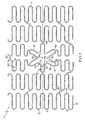
- Figure 1shows a flat pattern for an embodiment of a stent 10 which includes a side branch cell 30.
- the stent 10comprises a proximal end 11 and a distal end 13.
- the stent 10further comprises a plurality of serpentine bands 12 that comprise a plurality of struts 14 connected by turns 16. Adjacent serpentine bands 12 maybe connected by connectors 20.
- the interconnected stent elements, such as struts 14, turns 16 and connectors 20define a stent wall portion and further define a plurality of cells 8.
- Each cell 8comprise an aperture or void in the stent wall portion.
- the side branch cell 30defines a plurality of side branch petals 40.
- the side branch cell 30is different than any other cell 8 of the stent 10.
- the side branch cell 30is shaped differently, it may have a larger or smaller area, and/or may extend about the circumference or along the length of the stent 10 to a greater or lesser extent than any other cell 8 included in the stent 10.
- Each petal 40comprises a plurality of struts 36 and at least one turn 38.
- a strut 36may be straight along its length, and may be oriented in any suitable direction.
- a turn 38may be oriented in any suitable direction and in some embodiments may be oriented toward the center 34 of the side branch cell 30.
- Petals 40 which are adjacent to one another about the side branch cell 30may be connected to one another by a connecting portion 44.
- Each strut 36has a strut width 37.
- multiple struts 36 within a petal 40may have the same strut width 37.
- individual struts 36may have a varying width 37 along their length.
- Each turn 38has a turn width 39.
- Each turn 38may include a front side which may have a peak 35.
- Each turn 38may have a back side 50 opposite the front side.
- a back side 50may have a straight edge or may have curvature.
- the strut width 37 of a strut 36is less than the turn width 39 of a turn 39. Measurement of the strut width 37 is taken at a location on the strut 36 immediately adjacent to the turn 38.
- Each turn 38may have a turn width 39 to strut width 37 ratio.
- a turn width:strut width ratiomay be 1.5:1, 2:1, 2.5:1, 3:1, 3.5:1, etc.
- a turn 38may comprise a continuous piece of material across its turn width 39.
- a turn 38may further comprise a reinforcing material 33 which may be shaped to increase the turn width 39 of a turn 38.
- Figures 2 and 3show an embodiment of a petal 40 before and during expansion of a stent 10.
- Figure 2shows a petal 40 according to a nominal or unexpanded state.
- struts 36 of a petal 40may move 52 away from one another as shown in Figure 3 .
- the outward movement of the struts 36may cause the turn 38 to buckle outwardly or begin outward deployment 54 in a stent radial direction.
- struts 14 of the serpentine bands 12may generally remain within the bounds of the cylindrical wall portion of the stent 10 during and after expansion, the petals 40 may deploy outwardly beyond the outer diameter of the cylindrical wall.
- a stent 10 having a side branch cell 30may be delivered to a deployment site in an unexpanded state.
- the stent 10may be properly positioned and expanded.
- each petal 40 having a turn width 39 which is greater than a strut width 37may begin outward deployment 54 substantially in a stent radial direction.
- the shape of the struts 36 and turns 38 of the petals 40cause an outward lifting or partial deployment of the petals 40 as the stent is increased in diameter.
- the petals 40 of a side branch cell 30may be fully or at least partially outwardly deployed.
- an expansion mechanismsuch as an inflation balloon may be positioned to fully deploy the petals 40. Examples of some expansion mechanisms are disclosed in US 6,596,020 and US 6,835,203 .
- the thickness of a petal 40may be varied to encourage petal 40 deployment as the stent expands.
- a strut 36may have a strut thickness t s .
- a turn 38may have a turn thickness t t . When the turn thickness t t is less than the strut thickness t s in a petal 40, the petal 40 is more likely to begin an outward deployment upon expansion of the stent.
- the thickness of stent elementsmay be varied according to any suitable method.
- the thickness of a portion of a petal 40, such as a turn 38may be reduced by selectively removing a portion of the material, such as any suitable portion of the shaded region 63 of Figure 2 , for example by brushing, polishing, EDM machining, chemical processing, or any other suitable method.
- the stent 10may include serpentine bands 12 which extend about an entire circumference of the stent 10.
- serpentine bands 12may be located in portions of stent length that do not include a side branch cell 30.
- the stent 10may include one or more partial serpentine bands 60, which may extend from one side of a side branch cell 30 about the circumference of the stent 10 to the other side of the side branch cell 30.
- the design of struts 14 and turns 16 in a partial serpentine band 60may be similar to or different than the design geometry of the standard serpentine bands 12.
- a stent 10may include side branch connectors 56 which may connect between the side branch cell 30 and other portions of the stent 10.
- a side branch connector 56may extend from any portion of a side branch cell 30, such as a petal 40 or connecting portion 44, and connect to any other portion of the stent 10, such as a serpentine band 12 or a partial serpentine band 60.
- a side branch connector 56may include straight portions, peaks, valleys or other undulations. In some embodiments, a side branch connector 56 may comprise a flexible connector which may support an ostium when deployed in a vessel.
- Figure 4shows another embodiment of a side branch cell 30 which comprises a plurality of petals 40.
- Each petal 40may have an approximate longitudinal axis 42.
- a petal 40may have a longitudinal axis 42 which is oriented to extend substantially radially outwardly from the center 34 of the side branch cell 30.
- a longitudinal axis 42may pass through the centroid of the stent elements which comprise the petal 40.
- a reference box 22ais drawn about a portion of the side branch cell 30 which may be defined as a petal 40.
- Each petal 40comprises a plurality of struts 36 and at least one turn 38.
- a strut 36may be straight along its length, and may be oriented in any suitable direction.
- a turn 38may be oriented in any suitable direction.
- a turn 38may comprise a proximal turn 38p oriented with a peak facing the proximal end 11 (see Figure 1 ) of the stent 10, or a distal turn 38d oriented with a peak facing the distal end 13 (see Figure 1 ) of the stent 10.
- Petals 40which are adjacent to one another about the side branch cell 30 may be connected to one another by a connecting portion 44.
- a connecting portion 44may comprise a turn 38, a strut 36, or any combination of one or more turns 38 and one or more struts 36.
- a petal 40may include struts 36 that are oriented parallel to the longitudinal axis 18 of the stent 10. In some embodiments, a majority of the struts 36 or all of the struts 36 in a petal 40 may be oriented parallel to the longitudinal axis 18 of the stent 10. This may be true even though the longitudinal axis 42 of the petal 40 may be oriented at an angle with respect to the longitudinal axis 18 of the stent 10. In some embodiments, one or more struts 36 may be oriented at approximately 30° to 60° with respect to the longitudinal axis 18 of the stent 10. In some embodiments, one or more struts 36 may be oriented at approximately 45° with respect to the longitudinal axis 18 of the stent 10 (see Figure 5 ).
- Each petal 40may further comprise one or more appendages 70.
- An appendage 70may comprise a first strut 36a and a second strut 36b connected by a turn 38.
- an appendage 70may include a proximal turn 38p, or may include a distal turn 38d.
- An appendage 70may have an approximate longitudinal axis 72, and the approximate longitudinal axis 72 may be parallel to the longitudinal axis 18 of the stent 10.
- one or more petals 40may comprise a plurality of appendages 70.
- a single petal 40may include appendages 70 that are oriented in similar directions, in different directions or in opposite directions.
- a single petal 40may include at least one appendage 70 having a proximal turn 38p, and at least one other appendage 70 having a distal turn 38d.
- Each strut 36has a strut width 37.
- multiple struts 36 within a petal 40may have the same strut width 37.
- individual struts 36may have a varying width 37 along their length.
- Each turn 38has a turn width 39.
- the strut width 37 of a strut 36is less than the turn width 39 of a turn 38. Measurement of the strut width 37 may be taken at a location on the strut 36 immediately adjacent to the turn 38.
- a petal 40includes a plurality of turns 38, that may have a greater turn width 39 than other turns 38 of the petal 40.
- the turn 38 of a petal 40 which has the greatest turn width 39may be located closer to the center 34 of the side branch cell 30 than other turns 38 of the petal 40.
- the turn width 39may progressively decrease as the distance from the center 34 of the side branch cell 30 to the turn 38 increases.
- each petal 40 having a turn width 39 which is greater than a strut width 37may inherently begin outward deployment 54 substantially in a stent radial direction.
- the shape of the struts 36 and turns 38 of the petals 40may cause an outward lifting or partial deployment of the petals 40 as the stent is increased in diameter.
- the petals 40 of a side branch cell 30may be fully or at least partially outwardly deployed.
- a petal 40may have multiple turns 38, and the turn thickness t t of individual turns 38 may vary.
- turns 38 which are located closer to the center 34 of the side branch cell 30may have a larger turn thickness t t than other turns 38 of the petal 40.
- the turn thickness t tmay progressively increase as the distance from the center 34 of the side branch cell 30 to the turn 38 increases.
- the design of a side branch cell 30, and particularly the design of petals 40 having a plurality of struts 36 oriented parallel to the stent longitudinal axis 10,may allow for more struts 14 and turns 16 in a partial serpentine band 60 than prior art designs.
- the design of a side branch cell 30may also allow the design of the partial serpentine band(s) 60 to be consistent with the design of the standard serpentine bands 12. This allows the stent to provide more scaffolding support to vessel locations adjacent to the petal 40 region, particularly around juncture points between a main branch vessel and a side branch vessel, such as the carina and vessel areas contralateral to the carina.
- FIG. 5shows another embodiment of a side branch cell 30.
- Each petal 40may occupy an area of space on the surface of the stent.
- an embodiment of a petal 40ais shown with the approximate bounds of the petal 40a shaded.
- Each petal 40may include a longitudinal length component 46 or a distance between a proximal most point (e.g. 41) and a distal most point (e.g. 43) of the petal 40 as measured in a direction parallel to the stent longitudinal axis 18.
- a proximal most point 41may be defined as the point of a petal 40 that is closest to the proximal end 11 (see Figure 1 ) of the stent, and a distal most point 42 may be defined as the point of a petal 40 that is closest to the distal end 13 (see Figure 1 ) of the stent.
- a proximal most point 41 and a distal most point 43are specifically indicated in Figure 5 with respect to petal 40a, the location of a proximal most point and the location of a distal most point on any petal 40 may change as the shape of any petal 40 may change with stent crimping and/or stent expansion.
- Each petal 40may further include a circumferential length component 48, or a distance between opposed circumferential extremities 45, 47 of a petal 40 as measured in a direction about the circumference of the stent 10.
- a circumferential length component 48 of a petal 40may be perpendicular to the longitudinal length component 46 of the petal 40.
- a side branch cell 30may include a longitudinal length component 26, or a distance between proximal most and distal most points of the side branch cell 30 as measured parallel to the stent longitudinal axis 18.
- a side branch cell 30may also include a circumferential length component 28, or a distance between opposed extremities of the side branch cell 30 as measured in a direction about the circumference of the stent 10. The locations of a proximal most point, a distal most point, and the opposed circumferential extremities may change as a side branch cell 30 may change in size and shape with stent crimping and/or stent expansion.
- the longitudinal length component 26 of the side branch cell 30may be perpendicular to the circumferential length component 28.
- a side branch cell 30, including the design of the individual petals 40 within a side branch cell 30,may allow a stent 10 to expand more similarly to a standard stent not having a side branch cell 30.
- the circumferential length component 28, 48 of a petal 40 or a side branch cell 30may experience an increase that is proportionally larger than any related increase in the longitudinal length component 26, 46 of the respective petal 40 or side branch cell 30.
- a longitudinal length component 26, 46may remain the same or even reduce as the stent 10 expands.
- the geometric design of the petals 40, and particularly the petals 40 which have an approximate longitudinal axis 42 that is nonparallel to the stent longitudinal axis 18 and a plurality of struts 36 which are oriented parallel to the stent longitudinal axis 18,allows for a relatively large increase in the circumferential length component 28, 48 as compared to any change (i.e. increase or decrease) in the longitudinal length component 26, 46 of the petal 40 or side branch cell 30 during stent expansion.
- the petals 40may change shape, and the orientation of struts 36 and turns 38 may also change.
- Struts 36which are parallel to the stent longitudinal axis 18 in an unexpanded state may reorient on expansion and be nonparallel to the stent longitudinal axis 18 when the stent is expanded.
- Appendages 70may also change shape as the stent expands. In some embodiments, although an appendage 70 may change shape, the approximate longitudinal axis 72 of the appendage 70 may remain parallel to the stent longitudinal axis 18 after expansion.
- An appendage 70may have a longitudinal axis 72 which is a predetermined distance away from a longitudinal axis 31 of the side branch cell 30, as measured in a stent circumferential direction.
- Figure 5shows a first longitudinal axis 72a, a second longitudinal axis 72b and a third longitudinal axis 72c for three respective appendages 70.
- Three respective predetermined distances 74a, 74b, 74care shown between the side branch cell longitudinal axis 31 and the respective appendage longitudinal axes 72a, 72b, 72c.
- each appendage longitudinal axis 72may displace away from the side branch cell longitudinal axis 31.
- appendage longitudinal axis 72amay displace away from the side branch cell longitudinal axis 31.
- Appendage longitudinal axis 72bmay also displace away from the side branch cell longitudinal axis 31.
- the amount of displacement of appendage longitudinal axis 72bmay be greater than the amount of displacement of appendage longitudinal axis 72a.
- appendage longitudinal axis 72cmay also displace away from the side branch cell longitudinal axis 31, and the amount of displacement of appendage longitudinal axis 72c may be greater than the amount of displacement of appendage longitudinal axis 72b.
- the inventive stentsmay be made from any suitable biocompatible materials including one or more polymers, one or more metals or combinations of polymer(s) and metal(s).
- suitable materialsinclude biodegradable materials that are also biocompatible.
- biodegradableis meant that a material will undergo breakdown or decomposition into harmless compounds as part of a normal biological process.
- Suitable biodegradable materialsinclude polylactic acid, polyglycolic acid (PGA), collagen or other connective proteins or natural materials, polycaprolactone, hylauric acid, adhesive proteins, co-polymers of these materials as well as composites and combinations thereof and combinations of other biodegradable polymers.
- Other polymers that may be usedinclude polyester and polycarbonate copolymers.
- suitable metalsinclude, but are not limited to, stainless steel, titanium, tantalum, platinum, tungsten, gold and alloys of any of the above-mentioned metals.
- suitable alloysinclude platinum-iridium alloys, cobalt-chromium alloys including Elgiloy and Phynox, MP35N alloy and nickel-titanium alloys, for example, Nitinol.
- the inventive stentsmay be made of shape memory materials such as superelastic Nitinol or spring steel, or may be made of materials which are plastically deformable.
- shape memory materialssuch as superelastic Nitinol or spring steel, or may be made of materials which are plastically deformable.
- the stentmay be provided with a memorized shape and then deformed to a reduced diameter shape. The stent may restore itself to its memorized shape upon being heated to a transition temperature and having any restraints removed therefrom.
- inventive stentsmay be created by methods including cutting or etching a design from a tubular stock, from a flat sheet which is cut or etched and which is subsequently rolled or from one or more interwoven wires or braids. Any other suitable technique which is known in the art or which is subsequently developed may also be used to manufacture the inventive stents disclosed herein.
- the stent, a stent delivery system or other portion of the assemblymay include one or more areas, bands, coatings, members, etc. that is (are) detectable by imaging modalities such as X-Ray, MRI, ultrasound, etc. In some embodiments at least a portion of the stent and/or adjacent assembly is at least partially radiopaque.
- the stentis configured to include one or more mechanisms for the delivery of a therapeutic agent.
- the agentwill be in the form of a coating or other layer (or layers) of material placed on a surface region of the stent, which is adapted to be released at the site of stent implantation or areas adjacent thereto.
- a therapeutic agentmay be a drug or other pharmaceutical product such as non-genetic agents, genetic agents, cellular material, etc.
- suitable non-genetic therapeutic agentsinclude but are not limited to: anti-thrombogenic agents such as heparin, heparin derivatives, vascular cell growth promoters, growth factor inhibitors, Paclitaxel, etc.
- an agentincludes a genetic therapeutic agent, such a genetic agent may include but is not limited to: DNA, RNA and their respective derivatives and/or components; hedgehog proteins, etc.
- the cellular materialmay include but is not limited to: cells of human origin and/or non-human origin as well as their respective components and/or derivatives thereof.
- the polymer agentmay be a polystyrene-polyisobutylene-polystyrene triblock copolymer (SIBS), polyethylene oxide, silicone rubber and/or any other suitable substrate.
- SIBSpolystyrene-polyisobutylene-polystyrene triblock copolymer
Landscapes
- Health & Medical Sciences (AREA)
- Engineering & Computer Science (AREA)
- Biomedical Technology (AREA)
- Cardiology (AREA)
- Oral & Maxillofacial Surgery (AREA)
- Transplantation (AREA)
- Heart & Thoracic Surgery (AREA)
- Vascular Medicine (AREA)
- Life Sciences & Earth Sciences (AREA)
- Animal Behavior & Ethology (AREA)
- General Health & Medical Sciences (AREA)
- Public Health (AREA)
- Veterinary Medicine (AREA)
- Physics & Mathematics (AREA)
- Optics & Photonics (AREA)
- Prostheses (AREA)
Description
- A stent is a medical device introduced to a body lumen and is well known in the art. Typically, a stent is implanted in a blood vessel at the site of a stenosis or aneurysm endoluminally, i.e. by so-called "minimally invasive techniques" in which the stent in a radially reduced configuration, optionally restrained in a radially compressed configuration by a sheath and/or catheter, is delivered by a stent delivery system or "introducer" to the site where it is required. The introducer may enter the body from an access location outside the body, such as through the patient's skin, or by a "cut down" technique in which the entry blood vessel is exposed by minor surgical means.
- Stents, grafts, stent-grafts, vena cava filters, expandable frameworks, and similar implantable medical devices, collectively referred to hereinafter as stents, are radially expandable endoprostheses which are typically intravascular implants capable of being implanted transluminally and enlarged radially after being introduced percutaneously. Stents may be implanted in a variety of body lumens or vessels such as within the vascular system, urinary tracts, bile ducts, fallopian tubes, coronary vessels, secondary vessels, etc. Stents may be used to reinforce body vessels and to prevent restenosis following angioplasty in the vascular system. They may be self-expanding, expanded by an internal radial force, such as when mounted on a balloon, or a combination of self-expanding and balloon expandable (hybrid expandable).
- Stents may be created by methods including cutting or etching a design from a tubular stock, from a flat sheet which is cut or etched and which is subsequently rolled or from one or more interwoven wires or braids.
- Within the vasculature it is not uncommon for stenoses to form at a vessel bifurcation. A bifurcation is an area of the vasculature or other portion of the body where a first (or parent) vessel is bifurcated into two or more branch vessels. Where a stenotic lesion or lesions form at such a bifurcation, the lesion(s) can affect only one of the vessels (i.e., either of the branch vessels or the parent vessel) two of the vessels, or all three vessels. Many prior art stents however are not wholly satisfactory for use where the site of desired application of the stent is juxtaposed or extends across a bifurcation in an artery or vein such, for example, as the bifurcation in the mammalian aortic artery into the common iliac arteries.
- Stents and bifurcated stents are generally known. When treating a bifurcated vessel, it may desirable to use a stent having a side branch opening configured to provide fluid communication between the primary vessel and a secondary or branch vessel of the bifurcation. A secondary or branch stent may be received within and/or be positioned adjacent to the side branch opening of the primary stent.
- A side opening in some stents may further include a structural component, which when deployed, extends from the primary stent and into the branch vessel. In some instances a side branch structure (e.g. limb, arm, branch, etc.) exhibits expansion characteristics that are different from other portions of the primary stent. In some instances, it may be difficult to initiate an outward expansion of the side branch structure.
- There remains a need for a stent having a side branch structure which exhibits superior expansion characteristics.
- From
US 2004/0102836 A1 a stent in the form of a thin-walled, multi-cellular tubular structure has become known. The tubular structure has a longitudinal axis and the stent includes a plurality of circumferential sets of strut members. Each set of the strut members is longitudinally displaced from each other and connected to each other by longitudinally extending links. Each set of the strut members forms a closed and cylindrical portion of the stent. Further, each set of the strut members includes a plurality of connected curve sections and diagonal sections. - Without limiting the scope of the invention a brief summary of some of the claimed embodiments of the invention is set forth below. Additional details of the summarized embodiments of the invention and/or additional embodiments of the invention may be found in the Detailed Description of the Invention below.
- In at least one embodiment, a stent comprises a plurality of interconnected strut members. A portion of the interconnected strut members comprise a plurality of petals arranged to define a side branch cell. A first petal comprises a petal strut and a turn. The petal strut has a strut width, and the turn has a turn width. The turn width is greater than the strut width.
- In at least one embodiment, a stent has an unexpanded state and an expanded state. The stent generally defines a substantially cylindrical wall portion in both the unexpanded and expanded states. The stent includes a side branch cell comprising a plurality of petals. When the stent is expanded from the unexpanded state to the expanded state, a first petal desirably deploys outwardly in a stent radial direction beyond the outer diameter of the substantially cylindrical wall portion.
- These and other embodiments which characterize the invention are pointed out with particularity in the claims annexed hereto and forming a part hereof. However, for a better understanding of the invention, its advantages and objectives obtained by its use, reference should be made to the drawings which form a further part hereof and the accompanying descriptive matter, in which there are illustrated and described various embodiments of the invention.
- A detailed description of the invention is hereafter described with specific reference being made to the drawings.
Figure 1 shows an embodiment of a stent having a side branch cell.Figures 2 and 3 show an embodiment of a petal during stent expansion.Figure 4 shows another embodiment of a side branch cell.Figure 5 shows another embodiment of a side branch cell.- While this invention may be embodied in many different forms, there are described in detail herein specific embodiments of the invention. This description is an exemplification of the principles of the invention and is not intended to limit the invention to the particular embodiments illustrated.
- For the purposes of this disclosure, like reference numerals in the figures shall refer to like features unless otherwise indicated. Use of the term "parallel" is intended to describe an orientation in which two elements may be exactly parallel or substantially parallel to one another.
- The stent patterns depicted herein are generally shown and described as flat patterns. A person of ordinary skill in the art will understand that a cylindrical stent may be manufactured according to the design of the flat patterns disclosed, and that the stent elements defined by the patterns may form a cylindrical stent wall portion.
- Some examples of stent patterns which may be suitable for use in various embodiments of the invention are described in
US 5,922,021 ,US 6,123,721 ,US 6,334,870 ,US 6,478,816 ,US 6,348,065 andUS 6,325,826 . - Some examples of stents having a side opening and methods of deploying such stents are disclosed in
US 5,596,020 andUS 6,835,203 . Figure 1 shows a flat pattern for an embodiment of astent 10 which includes aside branch cell 30. Thestent 10 comprises a proximal end 11 and a distal end 13. Thestent 10 further comprises a plurality of serpentine bands 12 that comprise a plurality ofstruts 14 connected by turns 16. Adjacent serpentine bands 12 maybe connected by connectors 20. The interconnected stent elements, such asstruts 14, turns 16 and connectors 20 define a stent wall portion and further define a plurality of cells 8. Each cell 8 comprise an aperture or void in the stent wall portion.- The
side branch cell 30 defines a plurality ofside branch petals 40. Theside branch cell 30 is different than any other cell 8 of thestent 10. Theside branch cell 30 is shaped differently, it may have a larger or smaller area, and/or may extend about the circumference or along the length of thestent 10 to a greater or lesser extent than any other cell 8 included in thestent 10. - Each
petal 40 comprises a plurality ofstruts 36 and at least oneturn 38. Astrut 36 may be straight along its length, and may be oriented in any suitable direction. Aturn 38 may be oriented in any suitable direction and in some embodiments may be oriented toward the center 34 of theside branch cell 30.Petals 40 which are adjacent to one another about theside branch cell 30 may be connected to one another by a connectingportion 44. - Each
strut 36 has astrut width 37. In some embodiments,multiple struts 36 within apetal 40 may have thesame strut width 37. In some embodiments, individual struts 36 may have a varyingwidth 37 along their length. - Each
turn 38 has aturn width 39. Eachturn 38 may include a front side which may have a peak 35. Eachturn 38 may have a back side 50 opposite the front side. A back side 50 may have a straight edge or may have curvature. - Within a
petal 40, thestrut width 37 of astrut 36 is less than theturn width 39 of aturn 39. Measurement of thestrut width 37 is taken at a location on thestrut 36 immediately adjacent to theturn 38. - Each
turn 38 may have aturn width 39 to strutwidth 37 ratio. In some embodiments, a turn width:strut width ratio may be 1.5:1, 2:1, 2.5:1, 3:1, 3.5:1, etc. In some embodiments, aturn 38 may comprise a continuous piece of material across itsturn width 39. In some embodiments, aturn 38 may further comprise a reinforcing material 33 which may be shaped to increase theturn width 39 of aturn 38. Figures 2 and 3 show an embodiment of apetal 40 before and during expansion of astent 10.Figure 2 shows apetal 40 according to a nominal or unexpanded state. As thestent 10 is expanded, wherein the diameter of thestent 10 is increased and the size of aside branch cell 30 is increased, struts 36 of apetal 40 may move 52 away from one another as shown inFigure 3 . The outward movement of thestruts 36 may cause theturn 38 to buckle outwardly or begin outward deployment 54 in a stent radial direction.- While
struts 14 of the serpentine bands 12 may generally remain within the bounds of the cylindrical wall portion of thestent 10 during and after expansion, thepetals 40 may deploy outwardly beyond the outer diameter of the cylindrical wall. - Thus, a
stent 10 having aside branch cell 30 may be delivered to a deployment site in an unexpanded state. Thestent 10 may be properly positioned and expanded. As theside branch cell 30 expands, eachpetal 40 having aturn width 39 which is greater than astrut width 37 may begin outward deployment 54 substantially in a stent radial direction. The shape of thestruts 36 and turns 38 of thepetals 40 cause an outward lifting or partial deployment of thepetals 40 as the stent is increased in diameter. In some embodiments, when the stent reaches an expanded diameter, thepetals 40 of aside branch cell 30 may be fully or at least partially outwardly deployed. Where thepetals 40 may become partially deployed, an expansion mechanism such as an inflation balloon may be positioned to fully deploy thepetals 40. Examples of some expansion mechanisms are disclosed inUS 6,596,020 andUS 6,835,203 . - In some embodiments, the thickness of a
petal 40 may be varied to encouragepetal 40 deployment as the stent expands. Astrut 36 may have a strut thicknessts. Aturn 38 may have a turn thicknesstt. When the turn thicknesstt is less than the strut thicknessts in apetal 40, thepetal 40 is more likely to begin an outward deployment upon expansion of the stent. - The thickness of stent elements may be varied according to any suitable method. In some embodiments, the thickness of a portion of a
petal 40, such as aturn 38, may be reduced by selectively removing a portion of the material, such as any suitable portion of the shaded region 63 ofFigure 2 , for example by brushing, polishing, EDM machining, chemical processing, or any other suitable method. - Referring again to
Figure 1 , thestent 10 may include serpentine bands 12 which extend about an entire circumference of thestent 10. In some embodiments, serpentine bands 12 may be located in portions of stent length that do not include aside branch cell 30. In portions of length that do include aside branch cell 30, thestent 10 may include one or more partial serpentine bands 60, which may extend from one side of aside branch cell 30 about the circumference of thestent 10 to the other side of theside branch cell 30. The design ofstruts 14 and turns 16 in a partial serpentine band 60 may be similar to or different than the design geometry of the standard serpentine bands 12. - A
stent 10 may include side branch connectors 56 which may connect between theside branch cell 30 and other portions of thestent 10. A side branch connector 56 may extend from any portion of aside branch cell 30, such as apetal 40 or connectingportion 44, and connect to any other portion of thestent 10, such as a serpentine band 12 or a partial serpentine band 60. - In some embodiments, a side branch connector 56 may include straight portions, peaks, valleys or other undulations. In some embodiments, a side branch connector 56 may comprise a flexible connector which may support an ostium when deployed in a vessel.
Figure 4 shows another embodiment of aside branch cell 30 which comprises a plurality ofpetals 40. Eachpetal 40 may have an approximatelongitudinal axis 42. In some embodiments, apetal 40 may have alongitudinal axis 42 which is oriented to extend substantially radially outwardly from the center 34 of theside branch cell 30. Alongitudinal axis 42 may pass through the centroid of the stent elements which comprise thepetal 40. Areference box 22a is drawn about a portion of theside branch cell 30 which may be defined as apetal 40.- Each
petal 40 comprises a plurality ofstruts 36 and at least oneturn 38. Astrut 36 may be straight along its length, and may be oriented in any suitable direction. Aturn 38 may be oriented in any suitable direction. In some embodiments, aturn 38 may comprise aproximal turn 38p oriented with a peak facing the proximal end 11 (seeFigure 1 ) of thestent 10, or adistal turn 38d oriented with a peak facing the distal end 13 (seeFigure 1 ) of thestent 10.Petals 40 which are adjacent to one another about theside branch cell 30 may be connected to one another by a connectingportion 44. In various locations, a connectingportion 44 may comprise aturn 38, astrut 36, or any combination of one or more turns 38 and one or more struts 36. - A
petal 40 may includestruts 36 that are oriented parallel to thelongitudinal axis 18 of thestent 10. In some embodiments, a majority of thestruts 36 or all of thestruts 36 in apetal 40 may be oriented parallel to thelongitudinal axis 18 of thestent 10. This may be true even though thelongitudinal axis 42 of thepetal 40 may be oriented at an angle with respect to thelongitudinal axis 18 of thestent 10. In some embodiments, one ormore struts 36 may be oriented at approximately 30° to 60° with respect to thelongitudinal axis 18 of thestent 10. In some embodiments, one ormore struts 36 may be oriented at approximately 45° with respect to thelongitudinal axis 18 of the stent 10 (seeFigure 5 ). - Each
petal 40 may further comprise one ormore appendages 70. Anappendage 70 may comprise afirst strut 36a and asecond strut 36b connected by aturn 38. In some embodiments, anappendage 70 may include aproximal turn 38p, or may include adistal turn 38d. Anappendage 70 may have an approximate longitudinal axis 72, and the approximate longitudinal axis 72 may be parallel to thelongitudinal axis 18 of thestent 10. - In some embodiments, one or
more petals 40 may comprise a plurality ofappendages 70. Asingle petal 40 may includeappendages 70 that are oriented in similar directions, in different directions or in opposite directions. Asingle petal 40 may include at least oneappendage 70 having aproximal turn 38p, and at least oneother appendage 70 having adistal turn 38d. - Each
strut 36 has astrut width 37. In some embodiments,multiple struts 36 within apetal 40 may have thesame strut width 37. In some embodiments, individual struts 36 may have a varyingwidth 37 along their length. - Each
turn 38 has aturn width 39. Within apetal 40, thestrut width 37 of astrut 36 is less than theturn width 39 of aturn 38. Measurement of thestrut width 37 may be taken at a location on thestrut 36 immediately adjacent to theturn 38. Apetal 40 includes a plurality ofturns 38, that may have agreater turn width 39 than other turns 38 of thepetal 40. In some embodiments, theturn 38 of apetal 40 which has thegreatest turn width 39 may be located closer to the center 34 of theside branch cell 30 than other turns 38 of thepetal 40. In some embodiments, theturn width 39 may progressively decrease as the distance from the center 34 of theside branch cell 30 to theturn 38 increases. - As the
side branch cell 30 expands, eachpetal 40 having aturn width 39 which is greater than astrut width 37 may inherently begin outward deployment 54 substantially in a stent radial direction. The shape of thestruts 36 and turns 38 of thepetals 40 may cause an outward lifting or partial deployment of thepetals 40 as the stent is increased in diameter. When the stent reaches an expanded diameter, thepetals 40 of aside branch cell 30 may be fully or at least partially outwardly deployed. - In some embodiments, a
petal 40 may havemultiple turns 38, and the turn thicknesstt of individual turns 38 may vary. In some embodiments, turns 38 which are located closer to the center 34 of theside branch cell 30 may have a larger turn thicknesstt than other turns 38 of thepetal 40. In some embodiments, the turn thicknesstt may progressively increase as the distance from the center 34 of theside branch cell 30 to theturn 38 increases. - In some embodiments, the design of a
side branch cell 30, and particularly the design ofpetals 40 having a plurality ofstruts 36 oriented parallel to the stentlongitudinal axis 10, may allow formore struts 14 and turns 16 in a partial serpentine band 60 than prior art designs. The design of aside branch cell 30 may also allow the design of the partial serpentine band(s) 60 to be consistent with the design of the standard serpentine bands 12. This allows the stent to provide more scaffolding support to vessel locations adjacent to thepetal 40 region, particularly around juncture points between a main branch vessel and a side branch vessel, such as the carina and vessel areas contralateral to the carina. Figure 5 shows another embodiment of aside branch cell 30. Eachpetal 40 may occupy an area of space on the surface of the stent. For the purposes of the following disclosure, an embodiment of apetal 40a is shown with the approximate bounds of thepetal 40a shaded. Eachpetal 40 may include a longitudinal length component 46 or a distance between a proximal most point (e.g. 41) and a distal most point (e.g. 43) of thepetal 40 as measured in a direction parallel to the stentlongitudinal axis 18. A proximalmost point 41 may be defined as the point of apetal 40 that is closest to the proximal end 11 (seeFigure 1 ) of the stent, and a distalmost point 42 may be defined as the point of apetal 40 that is closest to the distal end 13 (seeFigure 1 ) of the stent. Although a proximalmost point 41 and a distalmost point 43 are specifically indicated inFigure 5 with respect topetal 40a, the location of a proximal most point and the location of a distal most point on anypetal 40 may change as the shape of anypetal 40 may change with stent crimping and/or stent expansion.- Each
petal 40 may further include acircumferential length component 48, or a distance between opposedcircumferential extremities petal 40 as measured in a direction about the circumference of thestent 10. As with the proximal most and distalmost points petal 40, the locations of points which comprise the opposedcircumferential extremities petal 40 may change with stent crimping and/or stent expansion. Thecircumferential length component 48 of apetal 40 may be perpendicular to the longitudinal length component 46 of thepetal 40. - Similar to the
circumferential length component 48 and longitudinal length component 46 of apetal 40, aside branch cell 30 may include a longitudinal length component 26, or a distance between proximal most and distal most points of theside branch cell 30 as measured parallel to the stentlongitudinal axis 18. Aside branch cell 30 may also include acircumferential length component 28, or a distance between opposed extremities of theside branch cell 30 as measured in a direction about the circumference of thestent 10. The locations of a proximal most point, a distal most point, and the opposed circumferential extremities may change as aside branch cell 30 may change in size and shape with stent crimping and/or stent expansion. The longitudinal length component 26 of theside branch cell 30 may be perpendicular to thecircumferential length component 28. - The geometric design of various embodiments of a
side branch cell 30, including the design of theindividual petals 40 within aside branch cell 30, may allow astent 10 to expand more similarly to a standard stent not having aside branch cell 30. Desirably, upon expansion, thecircumferential length component petal 40 or aside branch cell 30 may experience an increase that is proportionally larger than any related increase in the longitudinal length component 26, 46 of therespective petal 40 orside branch cell 30. In some embodiments, a longitudinal length component 26, 46 may remain the same or even reduce as thestent 10 expands. The geometric design of thepetals 40, and particularly thepetals 40 which have an approximatelongitudinal axis 42 that is nonparallel to the stentlongitudinal axis 18 and a plurality ofstruts 36 which are oriented parallel to the stentlongitudinal axis 18, allows for a relatively large increase in thecircumferential length component petal 40 orside branch cell 30 during stent expansion. - As a stent expands, the
petals 40 may change shape, and the orientation ofstruts 36 and turns 38 may also change.Struts 36 which are parallel to the stentlongitudinal axis 18 in an unexpanded state may reorient on expansion and be nonparallel to the stentlongitudinal axis 18 when the stent is expanded. Appendages 70 may also change shape as the stent expands. In some embodiments, although anappendage 70 may change shape, the approximate longitudinal axis 72 of theappendage 70 may remain parallel to the stentlongitudinal axis 18 after expansion.- An
appendage 70 may have a longitudinal axis 72 which is a predetermined distance away from alongitudinal axis 31 of theside branch cell 30, as measured in a stent circumferential direction.Figure 5 shows a firstlongitudinal axis 72a, a secondlongitudinal axis 72b and a thirdlongitudinal axis 72c for threerespective appendages 70. Three respectivepredetermined distances longitudinal axis 31 and the respective appendagelongitudinal axes - As the stent expands, each appendage longitudinal axis 72 may displace away from the side branch cell
longitudinal axis 31. The greater the distance 74 between the appendage longitudinal axis 72 and the side branch celllongitudinal axis 31, the greater the increase in the distance 74 may be. For example, during expansion, appendagelongitudinal axis 72a may displace away from the side branch celllongitudinal axis 31. Appendagelongitudinal axis 72b may also displace away from the side branch celllongitudinal axis 31. The amount of displacement of appendagelongitudinal axis 72b may be greater than the amount of displacement of appendagelongitudinal axis 72a. Similarly, appendagelongitudinal axis 72c may also displace away from the side branch celllongitudinal axis 31, and the amount of displacement of appendagelongitudinal axis 72c may be greater than the amount of displacement of appendagelongitudinal axis 72b. - The inventive stents may be made from any suitable biocompatible materials including one or more polymers, one or more metals or combinations of polymer(s) and metal(s). Examples of suitable materials include biodegradable materials that are also biocompatible. By biodegradable is meant that a material will undergo breakdown or decomposition into harmless compounds as part of a normal biological process. Suitable biodegradable materials include polylactic acid, polyglycolic acid (PGA), collagen or other connective proteins or natural materials, polycaprolactone, hylauric acid, adhesive proteins, co-polymers of these materials as well as composites and combinations thereof and combinations of other biodegradable polymers. Other polymers that may be used include polyester and polycarbonate copolymers. Examples of suitable metals include, but are not limited to, stainless steel, titanium, tantalum, platinum, tungsten, gold and alloys of any of the above-mentioned metals. Examples of suitable alloys include platinum-iridium alloys, cobalt-chromium alloys including Elgiloy and Phynox, MP35N alloy and nickel-titanium alloys, for example, Nitinol.
- The inventive stents may be made of shape memory materials such as superelastic Nitinol or spring steel, or may be made of materials which are plastically deformable. In the case of shape memory materials, the stent may be provided with a memorized shape and then deformed to a reduced diameter shape. The stent may restore itself to its memorized shape upon being heated to a transition temperature and having any restraints removed therefrom.
- The inventive stents may be created by methods including cutting or etching a design from a tubular stock, from a flat sheet which is cut or etched and which is subsequently rolled or from one or more interwoven wires or braids. Any other suitable technique which is known in the art or which is subsequently developed may also be used to manufacture the inventive stents disclosed herein.
- In some embodiments the stent, a stent delivery system or other portion of the assembly may include one or more areas, bands, coatings, members, etc. that is (are) detectable by imaging modalities such as X-Ray, MRI, ultrasound, etc. In some embodiments at least a portion of the stent and/or adjacent assembly is at least partially radiopaque.
- In some embodiments, at least a portion of the stent is configured to include one or more mechanisms for the delivery of a therapeutic agent. Often the agent will be in the form of a coating or other layer (or layers) of material placed on a surface region of the stent, which is adapted to be released at the site of stent implantation or areas adjacent thereto.
- A therapeutic agent may be a drug or other pharmaceutical product such as non-genetic agents, genetic agents, cellular material, etc. Some examples of suitable non-genetic therapeutic agents include but are not limited to: anti-thrombogenic agents such as heparin, heparin derivatives, vascular cell growth promoters, growth factor inhibitors, Paclitaxel, etc. Where an agent includes a genetic therapeutic agent, such a genetic agent may include but is not limited to: DNA, RNA and their respective derivatives and/or components; hedgehog proteins, etc. Where a therapeutic agent includes cellular material, the cellular material may include but is not limited to: cells of human origin and/or non-human origin as well as their respective components and/or derivatives thereof. Where the therapeutic agent includes a polymer agent, the polymer agent may be a polystyrene-polyisobutylene-polystyrene triblock copolymer (SIBS), polyethylene oxide, silicone rubber and/or any other suitable substrate.
- The above disclosure is intended to be illustrative and not exhaustive. This description will suggest many variations and alternatives to one of ordinary skill in this art.
Claims (10)
- A stent comprising a plurality of interconnected strut members defining a plurality of cells (8),characterised in that a plurality of said interconnected strut members comprises a plurality of petals (40), such that when the stent is expanded from the unexpanded state to the expanded state, a first petal deploys outwardly in a stent radial direction, the plurality of petals (40) defining a side branch cell (30) having a center, the side branch cell (30) being shaped differently than other cells (8) of the stent, a first petal (40) comprising a plurality of petal struts (36) and a turn (38), said petal struts (36) having a strut width (37), said turn (38) having a turn width (39), wherein the turn width (39) is greater than the strut width (37).
- The stent of claim 1, wherein said turn (38) comprises a continuous piece of material from a peak (35) of the turn (38) to a back side (50) of the turn (38).
- The stent of claim 1, wherein said turn (38) includes a back side (50), the back side (50) having curvature.
- The stent of claim 1, wherein the first petal (40) comprises a plurality of struts (36) and a plurality of turns (38) including a first turn and a second turn, the first turn located closer to the center of the side branch cell than the second turn, a turn width of the first turn being greater than a turn width of the second turn.
- The stent of claim 4, wherein the first petal (40) comprises a plurality of struts (36) which are oriented substantially parallel to a longitudinal axis of the stent.
- The stent of claim 1, wherein said turn width (39) is at least 1.5 times greater than said strut width (37).
- The stent of claim 1, wherein each petal (40) comprises a petal strut (36) having a strut width (37) and a turn (38) having a turn width (39), wherein the turn width (39) is greater than the strut width (37) in each petal (40).
- The stent of claim 1, wherein each petal (40) further comprises a plurality of turns (38), each turn (38) having a turn width (39), wherein for each petal (40), the turn having the greatest turn width is located closer to the center of the side branch cell (30) than other turns of the petal (40).
- The stent of any of the preceding claims, wherein said first petal (40) defines a longitudinal axis that is oriented in a radial direction with respect to the center of the side branch cell (30).
- The stent of any of the preceding claims, wherein each petal (40) defines a longitudinal axis that is oriented in a radial direction with respect to the center of the side branch cell (30).
Applications Claiming Priority (2)
| Application Number | Priority Date | Filing Date | Title |
|---|---|---|---|
| US11/138,196US8480728B2 (en) | 2005-05-26 | 2005-05-26 | Stent side branch deployment initiation geometry |
| PCT/US2006/011825WO2006127127A1 (en) | 2005-05-26 | 2006-03-29 | Stent side branch deployment initiation geometry |
Publications (2)
| Publication Number | Publication Date |
|---|---|
| EP1887993A1 EP1887993A1 (en) | 2008-02-20 |
| EP1887993B1true EP1887993B1 (en) | 2013-06-19 |
Family
ID=36630372
Family Applications (1)
| Application Number | Title | Priority Date | Filing Date |
|---|---|---|---|
| EP06758234.6AActiveEP1887993B1 (en) | 2005-05-26 | 2006-03-29 | Stent side branch deployment initiation geometry |
Country Status (6)
| Country | Link |
|---|---|
| US (1) | US8480728B2 (en) |
| EP (1) | EP1887993B1 (en) |
| JP (1) | JP2008541841A (en) |
| CA (1) | CA2600417A1 (en) |
| ES (1) | ES2422195T3 (en) |
| WO (1) | WO2006127127A1 (en) |
Families Citing this family (18)
| Publication number | Priority date | Publication date | Assignee | Title |
|---|---|---|---|---|
| US7341598B2 (en) | 1999-01-13 | 2008-03-11 | Boston Scientific Scimed, Inc. | Stent with protruding branch portion for bifurcated vessels |
| JP5054524B2 (en) | 2004-06-08 | 2012-10-24 | アドバンスド ステント テクノロジーズ, インコーポレイテッド | Stent with protruding branch for branch pipe |
| CN101102728B (en) | 2005-01-10 | 2011-06-22 | 曲利姆医疗股份有限公司 | Stand with self-deployable portion |
| US20070260304A1 (en)* | 2006-05-02 | 2007-11-08 | Daniel Gregorich | Bifurcated stent with minimally circumferentially projected side branch |
| EP2051673A2 (en)* | 2006-06-23 | 2009-04-29 | Boston Scientific Limited | Bifurcated stent with twisted hinges |
| US7842082B2 (en) | 2006-11-16 | 2010-11-30 | Boston Scientific Scimed, Inc. | Bifurcated stent |
| US8647376B2 (en)* | 2007-03-30 | 2014-02-11 | Boston Scientific Scimed, Inc. | Balloon fold design for deployment of bifurcated stent petal architecture |
| US7959669B2 (en)* | 2007-09-12 | 2011-06-14 | Boston Scientific Scimed, Inc. | Bifurcated stent with open ended side branch support |
| US7833266B2 (en) | 2007-11-28 | 2010-11-16 | Boston Scientific Scimed, Inc. | Bifurcated stent with drug wells for specific ostial, carina, and side branch treatment |
| US8277501B2 (en) | 2007-12-21 | 2012-10-02 | Boston Scientific Scimed, Inc. | Bi-stable bifurcated stent petal geometry |
| US8932340B2 (en) | 2008-05-29 | 2015-01-13 | Boston Scientific Scimed, Inc. | Bifurcated stent and delivery system |
| CN104116577B (en)* | 2014-06-27 | 2017-07-14 | 先健科技(深圳)有限公司 | Branch type overlay film frame |
| WO2018156848A1 (en) | 2017-02-24 | 2018-08-30 | Bolton Medical, Inc. | Vascular prosthesis with crimped adapter and methods of use |
| ES2954897T3 (en) | 2017-02-24 | 2023-11-27 | Bolton Medical Inc | Constrained Wrap Stent Graft Delivery System |
| WO2018156847A1 (en) | 2017-02-24 | 2018-08-30 | Bolton Medical, Inc. | Delivery system and method to radially constrict a stent graft |
| WO2018156850A1 (en) | 2017-02-24 | 2018-08-30 | Bolton Medical, Inc. | Stent graft with fenestration lock |
| WO2018156851A1 (en) | 2017-02-24 | 2018-08-30 | Bolton Medical, Inc. | Vascular prosthesis with moveable fenestration |
| CN116035788B (en)* | 2023-03-30 | 2023-06-16 | 杭州唯强医疗科技有限公司 | Window opening support, tectorial membrane support system and sewing method of window opening support |
Family Cites Families (192)
| Publication number | Priority date | Publication date | Assignee | Title |
|---|---|---|---|---|
| US4309994A (en)* | 1980-02-25 | 1982-01-12 | Grunwald Ronald P | Cardiovascular cannula |
| US4774949A (en) | 1983-06-14 | 1988-10-04 | Fogarty Thomas J | Deflector guiding catheter |
| DE8717643U1 (en)* | 1987-05-12 | 1989-09-21 | Domschke, Wolfram, Prof. Dr.med., 8520 Erlangen | Device for endoscopic-transpapillary probing of a bile duct system |
| US4769005A (en) | 1987-08-06 | 1988-09-06 | Robert Ginsburg | Selective catheter guide |
| US4896670A (en)* | 1988-04-19 | 1990-01-30 | C. R. Bard, Inc. | Kissing balloon catheter |
| US4994071A (en)* | 1989-05-22 | 1991-02-19 | Cordis Corporation | Bifurcating stent apparatus and method |
| US5147385A (en) | 1989-11-01 | 1992-09-15 | Schneider (Europe) A.G. | Stent and catheter for the introduction of the stent |
| AR246020A1 (en) | 1990-10-03 | 1994-03-30 | Hector Daniel Barone Juan Carl | A ball device for implanting an intraluminous aortic prosthesis, for repairing aneurysms. |
| ATE121303T1 (en) | 1990-10-04 | 1995-05-15 | Schneider Europ Ag | BALLOON DILATION CATHETER. |
| US5628783A (en) | 1991-04-11 | 1997-05-13 | Endovascular Technologies, Inc. | Bifurcated multicapsule intraluminal grafting system and method |
| US5304220A (en) | 1991-07-03 | 1994-04-19 | Maginot Thomas J | Method and apparatus for implanting a graft prosthesis in the body of a patient |
| FR2678508B1 (en) | 1991-07-04 | 1998-01-30 | Celsa Lg | DEVICE FOR REINFORCING VESSELS OF THE HUMAN BODY. |
| US5693084A (en) | 1991-10-25 | 1997-12-02 | Cook Incorporated | Expandable transluminal graft prosthesis for repair of aneurysm |
| US5387235A (en)* | 1991-10-25 | 1995-02-07 | Cook Incorporated | Expandable transluminal graft prosthesis for repair of aneurysm |
| CA2079417C (en)* | 1991-10-28 | 2003-01-07 | Lilip Lau | Expandable stents and method of making same |
| US5342387A (en) | 1992-06-18 | 1994-08-30 | American Biomed, Inc. | Artificial support for a blood vessel |
| US5487730A (en)* | 1992-12-30 | 1996-01-30 | Medtronic, Inc. | Balloon catheter with balloon surface retention means |
| US5395846A (en)* | 1993-06-25 | 1995-03-07 | Rhone-Poulenc Rorer Pharmaceuticals Inc. | Amino Bi- and tri-carbocyclic aklane bis-aryl squalene synthase inhibitors |
| IL106738A (en) | 1993-08-19 | 1998-02-08 | Mind E M S G Ltd | Device for external correction of deficient valves in venous junctions |
| US5632772A (en)* | 1993-10-21 | 1997-05-27 | Corvita Corporation | Expandable supportive branched endoluminal grafts |
| US5639278A (en) | 1993-10-21 | 1997-06-17 | Corvita Corporation | Expandable supportive bifurcated endoluminal grafts |
| US5325826A (en) | 1993-11-04 | 1994-07-05 | Ford Motor Company | Journal bearing oil diverter |
| US5607444A (en)* | 1993-12-02 | 1997-03-04 | Advanced Cardiovascular Systems, Inc. | Ostial stent for bifurcations |
| JP2703510B2 (en)* | 1993-12-28 | 1998-01-26 | アドヴァンスド カーディオヴァスキュラー システムズ インコーポレーテッド | Expandable stent and method of manufacturing the same |
| US5609627A (en) | 1994-02-09 | 1997-03-11 | Boston Scientific Technology, Inc. | Method for delivering a bifurcated endoluminal prosthesis |
| US5683451A (en)* | 1994-06-08 | 1997-11-04 | Cardiovascular Concepts, Inc. | Apparatus and methods for deployment release of intraluminal prostheses |
| US5636641A (en) | 1994-07-25 | 1997-06-10 | Advanced Cardiovascular Systems, Inc. | High strength member for intracorporeal use |
| US5609605A (en) | 1994-08-25 | 1997-03-11 | Ethicon, Inc. | Combination arterial stent |
| CA2175720C (en) | 1996-05-03 | 2011-11-29 | Ian M. Penn | Bifurcated stent and method for the manufacture and delivery of same |
| CA2134997C (en)* | 1994-11-03 | 2009-06-02 | Ian M. Penn | Stent |
| US5613980A (en)* | 1994-12-22 | 1997-03-25 | Chauhan; Tusharsindhu C. | Bifurcated catheter system and method |
| NL9500094A (en)* | 1995-01-19 | 1996-09-02 | Industrial Res Bv | Y-shaped stent and method of deployment. |
| US7204848B1 (en) | 1995-03-01 | 2007-04-17 | Boston Scientific Scimed, Inc. | Longitudinally flexible expandable stent |
| US6896696B2 (en)* | 1998-11-20 | 2005-05-24 | Scimed Life Systems, Inc. | Flexible and expandable stent |
| DE69622231T2 (en)* | 1995-03-01 | 2002-12-05 | Scimed Life Systems, Inc. | LENGTHFLEXIBLE AND EXPANDABLE STENT |
| US5709713A (en)* | 1995-03-31 | 1998-01-20 | Cardiovascular Concepts, Inc. | Radially expansible vascular prosthesis having reversible and other locking structures |
| FR2733682B1 (en)* | 1995-05-04 | 1997-10-31 | Dibie Alain | ENDOPROSTHESIS FOR THE TREATMENT OF STENOSIS ON BIFURCATIONS OF BLOOD VESSELS AND LAYING EQUIPMENT THEREFOR |
| US5591228A (en)* | 1995-05-09 | 1997-01-07 | Edoga; John K. | Methods for treating abdominal aortic aneurysms |
| US5707348A (en)* | 1995-06-06 | 1998-01-13 | Krogh; Steve S. | Intravenous bandage |
| US6033434A (en)* | 1995-06-08 | 2000-03-07 | Ave Galway Limited | Bifurcated endovascular stent and methods for forming and placing |
| FR2737969B1 (en) | 1995-08-24 | 1998-01-30 | Rieu Regis | INTRALUMINAL ENDOPROSTHESIS IN PARTICULAR FOR ANGIOPLASTY |
| US5824036A (en) | 1995-09-29 | 1998-10-20 | Datascope Corp | Stent for intraluminal grafts and device and methods for delivering and assembling same |
| US5669924A (en) | 1995-10-26 | 1997-09-23 | Shaknovich; Alexander | Y-shuttle stent assembly for bifurcating vessels and method of using the same |
| FR2740346A1 (en) | 1995-10-30 | 1997-04-30 | Debiotech Sa | ANGIOPLASTY DEVICE FOR ARTERIAL BIFURCATION |
| US5632762A (en)* | 1995-11-09 | 1997-05-27 | Hemodynamics, Inc. | Ostial stent balloon |
| US5824040A (en) | 1995-12-01 | 1998-10-20 | Medtronic, Inc. | Endoluminal prostheses and therapies for highly variable body lumens |
| US6203569B1 (en) | 1996-01-04 | 2001-03-20 | Bandula Wijay | Flexible stent |
| US6017363A (en) | 1997-09-22 | 2000-01-25 | Cordis Corporation | Bifurcated axially flexible stent |
| US6436104B2 (en)* | 1996-01-26 | 2002-08-20 | Cordis Corporation | Bifurcated axially flexible stent |
| US6258116B1 (en) | 1996-01-26 | 2001-07-10 | Cordis Corporation | Bifurcated axially flexible stent |
| US5824042A (en)* | 1996-04-05 | 1998-10-20 | Medtronic, Inc. | Endoluminal prostheses having position indicating markers |
| BE1010183A3 (en) | 1996-04-25 | 1998-02-03 | Dereume Jean Pierre Georges Em | Luminal endoprosthesis FOR BRANCHING CHANNELS OF A HUMAN OR ANIMAL BODY AND MANUFACTURING METHOD THEREOF. |
| US5922021A (en) | 1996-04-26 | 1999-07-13 | Jang; G. David | Intravascular stent |
| UA58485C2 (en)* | 1996-05-03 | 2003-08-15 | Медінол Лтд. | Method for manufacture of bifurcated stent (variants) and bifurcated stent (variants) |
| US6251133B1 (en) | 1996-05-03 | 2001-06-26 | Medinol Ltd. | Bifurcated stent with improved side branch aperture and method of making same |
| US6440165B1 (en) | 1996-05-03 | 2002-08-27 | Medinol, Ltd. | Bifurcated stent with improved side branch aperture and method of making same |
| US6770092B2 (en)* | 1996-05-03 | 2004-08-03 | Medinol Ltd. | Method of delivering a bifurcated stent |
| US5851464A (en) | 1996-05-13 | 1998-12-22 | Cordis Corporation | Method of making a fuseless soft tip catheter |
| US5669932A (en) | 1996-05-29 | 1997-09-23 | Isostent, Inc. | Means for accurately positioning an expandable stent |
| AU2785597A (en)* | 1996-05-31 | 1998-01-05 | Bard Galway Limited | Bifurcated endovascular stents and method and apparatus for their placement |
| US5617878A (en)* | 1996-05-31 | 1997-04-08 | Taheri; Syde A. | Stent and method for treatment of aortic occlusive disease |
| US5755773A (en)* | 1996-06-04 | 1998-05-26 | Medtronic, Inc. | Endoluminal prosthetic bifurcation shunt |
| US7238197B2 (en)* | 2000-05-30 | 2007-07-03 | Devax, Inc. | Endoprosthesis deployment system for treating vascular bifurcations |
| FR2749500B1 (en)* | 1996-06-06 | 1998-11-20 | Jacques Seguin | DEVICE ALLOWING THE TREATMENT OF BODY DUCTS AT THE LEVEL OF A BIFURCATION |
| US8728143B2 (en)* | 1996-06-06 | 2014-05-20 | Biosensors International Group, Ltd. | Endoprosthesis deployment system for treating vascular bifurcations |
| US5697971A (en) | 1996-06-11 | 1997-12-16 | Fischell; Robert E. | Multi-cell stent with cells having differing characteristics |
| US5676697A (en) | 1996-07-29 | 1997-10-14 | Cardiovascular Dynamics, Inc. | Two-piece, bifurcated intraluminal graft for repair of aneurysm |
| US5749825A (en)* | 1996-09-18 | 1998-05-12 | Isostent, Inc. | Means method for treatment of stenosed arterial bifurcations |
| US5755778A (en)* | 1996-10-16 | 1998-05-26 | Nitinol Medical Technologies, Inc. | Anastomosis device |
| US6599316B2 (en) | 1996-11-04 | 2003-07-29 | Advanced Stent Technologies, Inc. | Extendible stent apparatus |
| US6692483B2 (en)* | 1996-11-04 | 2004-02-17 | Advanced Stent Technologies, Inc. | Catheter with attached flexible side sheath |
| US6835203B1 (en) | 1996-11-04 | 2004-12-28 | Advanced Stent Technologies, Inc. | Extendible stent apparatus |
| US7341598B2 (en) | 1999-01-13 | 2008-03-11 | Boston Scientific Scimed, Inc. | Stent with protruding branch portion for bifurcated vessels |
| US7220275B2 (en) | 1996-11-04 | 2007-05-22 | Advanced Stent Technologies, Inc. | Stent with protruding branch portion for bifurcated vessels |
| US6596020B2 (en) | 1996-11-04 | 2003-07-22 | Advanced Stent Technologies, Inc. | Method of delivering a stent with a side opening |
| US7591846B2 (en) | 1996-11-04 | 2009-09-22 | Boston Scientific Scimed, Inc. | Methods for deploying stents in bifurcations |
| EP1723931B1 (en) | 1996-11-04 | 2012-01-04 | Advanced Stent Technologies, Inc. | Extendible stent apparatus and method for deploying the same |
| US6325826B1 (en) | 1998-01-14 | 2001-12-04 | Advanced Stent Technologies, Inc. | Extendible stent apparatus |
| US5972017A (en) | 1997-04-23 | 1999-10-26 | Vascular Science Inc. | Method of installing tubular medical graft connectors |
| FR2756173B1 (en) | 1996-11-22 | 1999-02-12 | Marcade Jean Paul | MODULAR AND EXPANDABLE ENDOPROSTHESIS FOR THE ARTERIAL NETWORK |
| US5749890A (en)* | 1996-12-03 | 1998-05-12 | Shaknovich; Alexander | Method and system for stent placement in ostial lesions |
| DE29701758U1 (en) | 1997-02-01 | 1997-03-27 | Jomed Implantate GmbH, 72414 Rangendingen | Radially expandable stent for implantation in a body vessel, particularly in the area of a vascular branch |
| DE29701883U1 (en) | 1997-02-04 | 1997-03-27 | Beck, Harry, 71732 Tamm | Central lubrication |
| US5720735A (en)* | 1997-02-12 | 1998-02-24 | Dorros; Gerald | Bifurcated endovascular catheter |
| US6096073A (en) | 1997-02-25 | 2000-08-01 | Scimed Life Systems, Inc. | Method of deploying a stent at a lesion site located at a bifurcation in a parent vessel |
| US20020133222A1 (en)* | 1997-03-05 | 2002-09-19 | Das Gladwin S. | Expandable stent having a plurality of interconnected expansion modules |
| EP1011532B1 (en) | 1997-04-23 | 2014-05-07 | Ethicon Endo-Surgery, Inc. | Bifurcated stent and distal protection system |
| US6033433A (en)* | 1997-04-25 | 2000-03-07 | Scimed Life Systems, Inc. | Stent configurations including spirals |
| US6013054A (en)* | 1997-04-28 | 2000-01-11 | Advanced Cardiovascular Systems, Inc. | Multifurcated balloon catheter |
| US6245102B1 (en)* | 1997-05-07 | 2001-06-12 | Iowa-India Investments Company Ltd. | Stent, stent graft and stent valve |
| ATE336958T1 (en) | 1997-05-07 | 2006-09-15 | Cordis Corp | INTRAVASCULAR STENT AND SYSTEM FOR INSERTING (OBSTRUCTION OF THE OSTIUM OF A VESSEL) |
| DE29708803U1 (en) | 1997-05-17 | 1997-07-31 | Jomed Implantate GmbH, 72414 Rangendingen | Radially expandable stent for implantation in a body vessel in the area of a vascular branch |
| US5906641A (en) | 1997-05-27 | 1999-05-25 | Schneider (Usa) Inc | Bifurcated stent graft |
| CA2424551A1 (en)* | 1997-05-27 | 1998-11-27 | Schneider (Usa) Inc. | Stent and stent-graft for treating branched vessels |
| EP0891751A1 (en) | 1997-07-18 | 1999-01-20 | Thomas Prof. Dr. Ischinger | Vascular stent for bifurcations, sidebranches and ostial lesions and an application catheter and method for implantation |
| IT1293690B1 (en) | 1997-08-08 | 1999-03-08 | Sorin Biomedica Cardio Spa | ANGIOPLASTIC STENT, PARTICULARLY FOR THE TREATMENT OF AORTO-HOSPITAL AND HOSPITAL INJURIES. |
| US6165195A (en) | 1997-08-13 | 2000-12-26 | Advanced Cardiovascylar Systems, Inc. | Stent and catheter assembly and method for treating bifurcations |
| US6361544B1 (en)* | 1997-08-13 | 2002-03-26 | Advanced Cardiovascular Systems, Inc. | Stent and catheter assembly and method for treating bifurcations |
| US6520988B1 (en) | 1997-09-24 | 2003-02-18 | Medtronic Ave, Inc. | Endolumenal prosthesis and method of use in bifurcation regions of body lumens |
| US6086611A (en) | 1997-09-25 | 2000-07-11 | Ave Connaught | Bifurcated stent |
| US5893887A (en)* | 1997-10-14 | 1999-04-13 | Iowa-India Investments Company Limited | Stent for positioning at junction of bifurcated blood vessel and method of making |
| US6033435A (en)* | 1997-11-03 | 2000-03-07 | Divysio Solutions Ulc | Bifurcated stent and method for the manufacture and delivery of same |
| EP0951310B1 (en) | 1997-11-07 | 2005-05-18 | Ave Connaught | Balloon catheter for repairing bifurcated vessels |
| US6030414A (en)* | 1997-11-13 | 2000-02-29 | Taheri; Syde A. | Variable stent and method for treatment of arterial disease |
| US5961548A (en) | 1997-11-18 | 1999-10-05 | Shmulewitz; Ascher | Bifurcated two-part graft and methods of implantation |
| CA2220864A1 (en) | 1998-01-20 | 1999-07-20 | Nisar Huq | A bifurcation stent |
| US6395018B1 (en)* | 1998-02-09 | 2002-05-28 | Wilfrido R. Castaneda | Endovascular graft and process for bridging a defect in a main vessel near one of more branch vessels |
| DE69929036T2 (en)* | 1998-02-12 | 2006-08-31 | Thomas R. North Vancouver Marotta | ENDOVASCULAR PROSTHESIS |
| AU2684499A (en) | 1998-02-17 | 1999-08-30 | G. David Jang | Tubular stent consists of chevron-shape expansion struts and ipsilaterally attached m-frame connectors |
| US5938697A (en) | 1998-03-04 | 1999-08-17 | Scimed Life Systems, Inc. | Stent having variable properties |
| US6113579A (en) | 1998-03-04 | 2000-09-05 | Scimed Life Systems, Inc. | Catheter tip designs and methods for improved stent crossing |
| US6099497A (en) | 1998-03-05 | 2000-08-08 | Scimed Life Systems, Inc. | Dilatation and stent delivery system for bifurcation lesions |
| US6093203A (en) | 1998-05-13 | 2000-07-25 | Uflacker; Renan | Stent or graft support structure for treating bifurcated vessels having different diameter portions and methods of use and implantation |
| US6168621B1 (en)* | 1998-05-29 | 2001-01-02 | Scimed Life Systems, Inc. | Balloon expandable stent with a self-expanding portion |
| US6129738A (en) | 1998-06-20 | 2000-10-10 | Medtronic Ave, Inc. | Method and apparatus for treating stenoses at bifurcated regions |
| US6261319B1 (en) | 1998-07-08 | 2001-07-17 | Scimed Life Systems, Inc. | Stent |
| US6264662B1 (en) | 1998-07-21 | 2001-07-24 | Sulzer Vascutek Ltd. | Insertion aid for a bifurcated prosthesis |
| US6143002A (en) | 1998-08-04 | 2000-11-07 | Scimed Life Systems, Inc. | System for delivering stents to bifurcation lesions |
| US6117117A (en)* | 1998-08-24 | 2000-09-12 | Advanced Cardiovascular Systems, Inc. | Bifurcated catheter assembly |
| US6017324A (en)* | 1998-10-20 | 2000-01-25 | Tu; Lily Chen | Dilatation catheter having a bifurcated balloon |
| US6293967B1 (en) | 1998-10-29 | 2001-09-25 | Conor Medsystems, Inc. | Expandable medical device with ductile hinges |
| DE69937415T2 (en)* | 1998-11-20 | 2008-02-14 | Boston Scientific Ltd., St. Michael | Longitudinally flexible and expandable stent |
| WO2000033769A1 (en) | 1998-12-11 | 2000-06-15 | Endologix, Inc. | Endoluminal vascular prosthesis |
| US6059824A (en)* | 1998-12-23 | 2000-05-09 | Taheri; Syde A. | Mated main and collateral stent and method for treatment of arterial disease |
| US7655030B2 (en) | 2003-07-18 | 2010-02-02 | Boston Scientific Scimed, Inc. | Catheter balloon systems and methods |
| US20050060027A1 (en)* | 1999-01-13 | 2005-03-17 | Advanced Stent Technologies, Inc. | Catheter balloon systems and methods |
| CA2360587A1 (en)* | 1999-01-15 | 2000-07-20 | Darin C. Gittings | Methods and devices for forming vascular anastomoses |
| IT1309583B1 (en) | 1999-02-26 | 2002-01-24 | Ams Italia S R L | PERFECTED CATHETER FOR VASCULAR INTERVENTIONS. |
| US6261316B1 (en) | 1999-03-11 | 2001-07-17 | Endologix, Inc. | Single puncture bifurcation graft deployment system |
| US6258099B1 (en) | 1999-03-31 | 2001-07-10 | Scimed Life Systems, Inc. | Stent security balloon/balloon catheter |
| US6325825B1 (en)* | 1999-04-08 | 2001-12-04 | Cordis Corporation | Stent with variable wall thickness |
| US6290673B1 (en)* | 1999-05-20 | 2001-09-18 | Conor Medsystems, Inc. | Expandable medical device delivery system and method |
| US6884258B2 (en)* | 1999-06-04 | 2005-04-26 | Advanced Stent Technologies, Inc. | Bifurcation lesion stent delivery using multiple guidewires |
| US7387639B2 (en) | 1999-06-04 | 2008-06-17 | Advanced Stent Technologies, Inc. | Short sleeve stent delivery catheter and methods |
| DE19934923A1 (en) | 1999-07-20 | 2001-01-25 | Biotronik Mess & Therapieg | Balloon catheter |
| DE19938377A1 (en) | 1999-08-06 | 2001-03-01 | Biotronik Mess & Therapieg | Stent for vascular branching |
| US6293968B1 (en) | 1999-09-02 | 2001-09-25 | Syde A. Taheri | Inflatable intraluminal vascular stent |
| WO2001021095A2 (en) | 1999-09-23 | 2001-03-29 | Advanced Stent Technologies, Inc. | Bifurcation stent system and method |
| US6689156B1 (en) | 1999-09-23 | 2004-02-10 | Advanced Stent Technologies, Inc. | Stent range transducers and methods of use |
| US6383213B2 (en)* | 1999-10-05 | 2002-05-07 | Advanced Cardiovascular Systems, Inc. | Stent and catheter assembly and method for treating bifurcations |
| US6387120B2 (en) | 1999-12-09 | 2002-05-14 | Advanced Cardiovascular Systems, Inc. | Stent and catheter assembly and method for treating bifurcations |
| US6254593B1 (en)* | 1999-12-10 | 2001-07-03 | Advanced Cardiovascular Systems, Inc. | Bifurcated stent delivery system having retractable sheath |
| US6361555B1 (en)* | 1999-12-15 | 2002-03-26 | Advanced Cardiovascular Systems, Inc. | Stent and stent delivery assembly and method of use |
| US6325822B1 (en) | 2000-01-31 | 2001-12-04 | Scimed Life Systems, Inc. | Braided stent having tapered filaments |
| AU769900B2 (en) | 2000-03-03 | 2004-02-05 | Cook Medical Technologies Llc | Endovascular device having a stent |
| US6210433B1 (en)* | 2000-03-17 | 2001-04-03 | LARRé JORGE CASADO | Stent for treatment of lesions of bifurcated vessels |
| US6468301B1 (en) | 2000-03-27 | 2002-10-22 | Aga Medical Corporation | Repositionable and recapturable vascular stent/graft |
| US6334864B1 (en)* | 2000-05-17 | 2002-01-01 | Aga Medical Corp. | Alignment member for delivering a non-symmetric device with a predefined orientation |
| US7101391B2 (en) | 2000-09-18 | 2006-09-05 | Inflow Dynamics Inc. | Primarily niobium stent |
| US6669722B2 (en)* | 2000-09-22 | 2003-12-30 | Cordis Corporation | Stent with optimal strength and radiopacity characteristics |
| US20020116049A1 (en)* | 2000-09-22 | 2002-08-22 | Scimed Life Systems, Inc. | Stent |
| WO2002030329A2 (en)* | 2000-10-13 | 2002-04-18 | Rex Medical, L.P. | Covered stents with side branch |
| US6582394B1 (en) | 2000-11-14 | 2003-06-24 | Advanced Cardiovascular Systems, Inc. | Stent and catheter assembly and method for treating bifurcated vessels |
| US6645242B1 (en) | 2000-12-11 | 2003-11-11 | Stephen F. Quinn | Bifurcated side-access intravascular stent graft |
| WO2004026180A2 (en) | 2000-12-27 | 2004-04-01 | Advanced Stent Technologies, Inc. | Stent with protruding branch portion for bifurcated vessels |
| US6695877B2 (en)* | 2001-02-26 | 2004-02-24 | Scimed Life Systems | Bifurcated stent |
| WO2002067816A1 (en) | 2001-02-26 | 2002-09-06 | Scimed Life Systems, Inc. | Bifurcated stent and delivery system |
| US20030097169A1 (en)* | 2001-02-26 | 2003-05-22 | Brucker Gregory G. | Bifurcated stent and delivery system |
| FR2822370B1 (en) | 2001-03-23 | 2004-03-05 | Perouse Lab | TUBULAR ENDOPROSTHESIS COMPRISING A DEFORMABLE RING AND REQUIRED OF INTERVENTION FOR ITS IMPLANTATION |
| US8337540B2 (en) | 2001-05-17 | 2012-12-25 | Advanced Cardiovascular Systems, Inc. | Stent for treating bifurcations and method of use |
| US6749628B1 (en) | 2001-05-17 | 2004-06-15 | Advanced Cardiovascular Systems, Inc. | Stent and catheter assembly and method for treating bifurcations |
| US20020193872A1 (en) | 2001-06-18 | 2002-12-19 | Trout Hugh H. | Prosthetic graft assembly and method of use |
| US6743259B2 (en) | 2001-08-03 | 2004-06-01 | Core Medical, Inc. | Lung assist apparatus and methods for use |
| ES2319621T3 (en)* | 2001-08-23 | 2009-05-11 | Darrell C. Gumm | ROTARY SYSTEM OF IMPLANT OF ENDOVASCULAR PROTESIS FOR ACCSO OF SIDE BRANCH AND PROTECTION. |
| US7252679B2 (en)* | 2001-09-13 | 2007-08-07 | Cordis Corporation | Stent with angulated struts |
| US7004963B2 (en)* | 2001-09-14 | 2006-02-28 | Scimed Life Systems, Inc. | Conformable balloons |
| US6939368B2 (en) | 2002-01-17 | 2005-09-06 | Scimed Life Systems, Inc. | Delivery system for self expanding stents for use in bifurcated vessels |
| US20040117003A1 (en) | 2002-05-28 | 2004-06-17 | The Cleveland Clinic Foundation | Minimally invasive treatment system for aortic aneurysms |
| US6858038B2 (en)* | 2002-06-21 | 2005-02-22 | Richard R. Heuser | Stent system |
| US6761734B2 (en) | 2002-07-22 | 2004-07-13 | William S. Suhr | Segmented balloon catheter for stenting bifurcation lesions |
| AU2003276920A1 (en) | 2002-09-20 | 2004-04-08 | Innovational Holdings, Llc | Expandable medical device with openings for delivery of multiple beneficial agents |
| US20040059406A1 (en)* | 2002-09-20 | 2004-03-25 | Cully Edward H. | Medical device amenable to fenestration |
| US7326242B2 (en)* | 2002-11-05 | 2008-02-05 | Boston Scientific Scimed, Inc. | Asymmetric bifurcated crown |
| US6896697B1 (en)* | 2002-12-30 | 2005-05-24 | Advanced Cardiovascular Systems, Inc. | Intravascular stent |
| US7314480B2 (en) | 2003-02-27 | 2008-01-01 | Boston Scientific Scimed, Inc. | Rotating balloon expandable sheath bifurcation delivery |
| US7731747B2 (en) | 2003-04-14 | 2010-06-08 | Tryton Medical, Inc. | Vascular bifurcation prosthesis with multiple thin fronds |
| US20040225345A1 (en) | 2003-05-05 | 2004-11-11 | Fischell Robert E. | Means and method for stenting bifurcated vessels |
| US8298280B2 (en)* | 2003-08-21 | 2012-10-30 | Boston Scientific Scimed, Inc. | Stent with protruding branch portion for bifurcated vessels |
| US7425219B2 (en) | 2003-10-10 | 2008-09-16 | Arshad Quadri | System and method for endoluminal grafting of bifurcated and branched vessels |
| US8808351B2 (en)* | 2003-10-10 | 2014-08-19 | Cook Medical Technologies Llc | Stretchable prosthesis fenestration |
| US20050131526A1 (en) | 2003-12-10 | 2005-06-16 | Shing-Chiu Wong | Stent and balloon system for bifurcated vessels and lesions |
| US7686841B2 (en) | 2003-12-29 | 2010-03-30 | Boston Scientific Scimed, Inc. | Rotating balloon expandable sheath bifurcation delivery system |
| US7922753B2 (en) | 2004-01-13 | 2011-04-12 | Boston Scientific Scimed, Inc. | Bifurcated stent delivery system |
| US7225518B2 (en) | 2004-02-23 | 2007-06-05 | Boston Scientific Scimed, Inc. | Apparatus for crimping a stent assembly |
| US20050209673A1 (en) | 2004-03-04 | 2005-09-22 | Y Med Inc. | Bifurcation stent delivery devices |
| JP5054524B2 (en)* | 2004-06-08 | 2012-10-24 | アドバンスド ステント テクノロジーズ, インコーポレイテッド | Stent with protruding branch for branch pipe |
| US20060041303A1 (en)* | 2004-08-18 | 2006-02-23 | Israel Henry M | Guidewire with stopper |
| JP4575451B2 (en) | 2004-09-02 | 2010-11-04 | メッド・インスティテュート・インコーポレイテッド | Modular prosthesis and method for vascular branches |
| US20060079956A1 (en)* | 2004-09-15 | 2006-04-13 | Conor Medsystems, Inc. | Bifurcation stent with crushable end and method for delivery of a stent to a bifurcation |
| CN101102728B (en) | 2005-01-10 | 2011-06-22 | 曲利姆医疗股份有限公司 | Stand with self-deployable portion |
| US20060271161A1 (en)* | 2005-05-26 | 2006-11-30 | Boston Scientific Scimed, Inc. | Selective treatment of stent side branch petals |
| US8702777B2 (en)* | 2005-08-22 | 2014-04-22 | Incept, Llc | Steep-taper flared stents and apparatus and methods for delivering them |
- 2005
- 2005-05-26USUS11/138,196patent/US8480728B2/ennot_activeExpired - Fee Related
- 2006
- 2006-03-29JPJP2008513472Apatent/JP2008541841A/enactivePending
- 2006-03-29WOPCT/US2006/011825patent/WO2006127127A1/enactiveApplication Filing
- 2006-03-29CACA002600417Apatent/CA2600417A1/ennot_activeAbandoned
- 2006-03-29EPEP06758234.6Apatent/EP1887993B1/enactiveActive
- 2006-03-29ESES06758234Tpatent/ES2422195T3/enactiveActive
Also Published As
| Publication number | Publication date |
|---|---|
| US20060271160A1 (en) | 2006-11-30 |
| EP1887993A1 (en) | 2008-02-20 |
| ES2422195T3 (en) | 2013-09-09 |
| CA2600417A1 (en) | 2006-11-30 |
| US8480728B2 (en) | 2013-07-09 |
| JP2008541841A (en) | 2008-11-27 |
| WO2006127127A1 (en) | 2006-11-30 |
Similar Documents
| Publication | Publication Date | Title |
|---|---|---|
| EP1887993B1 (en) | Stent side branch deployment initiation geometry | |
| US8317855B2 (en) | Crimpable and expandable side branch cell | |
| EP1940315B1 (en) | Stent with expanding side branch geometry | |
| US7540881B2 (en) | Bifurcation stent pattern | |
| EP1933776B1 (en) | Crown stent assembly | |
| US8298278B2 (en) | Bifurcated stent with improvement securement | |
| US20090069881A1 (en) | Bifurcated Stent with Open Ended Side Branch Support | |
| WO2007030159A1 (en) | Overlapping stent | |
| US20070225798A1 (en) | Side branch stent | |
| WO2007064371A1 (en) | Bifurcation stent with overlapping crimped struts | |
| US20070260304A1 (en) | Bifurcated stent with minimally circumferentially projected side branch | |
| EP1993486A1 (en) | Bifurcation stent with uniform side branch projection | |
| EP1991175A1 (en) | Tapered strength rings on a bifurcated stent petal | |
| EP1993488A1 (en) | Bifurcated stent with surface area gradient | |
| EP1928368B1 (en) | Hybrid bifurcated stent |
Legal Events
| Date | Code | Title | Description |
|---|---|---|---|
| PUAI | Public reference made under article 153(3) epc to a published international application that has entered the european phase | Free format text:ORIGINAL CODE: 0009012 | |
| 17P | Request for examination filed | Effective date:20071123 | |
| AK | Designated contracting states | Kind code of ref document:A1 Designated state(s):AT BE BG CH CY CZ DE DK EE ES FI FR GB GR HU IE IS IT LI LT LU LV MC NL PL PT RO SE SI SK TR | |
| DAX | Request for extension of the european patent (deleted) | ||
| 17Q | First examination report despatched | Effective date:20100208 | |
| GRAP | Despatch of communication of intention to grant a patent | Free format text:ORIGINAL CODE: EPIDOSNIGR1 | |
| GRAS | Grant fee paid | Free format text:ORIGINAL CODE: EPIDOSNIGR3 | |
| GRAA | (expected) grant | Free format text:ORIGINAL CODE: 0009210 | |
| AK | Designated contracting states | Kind code of ref document:B1 Designated state(s):AT BE BG CH CY CZ DE DK EE ES FI FR GB GR HU IE IS IT LI LT LU LV MC NL PL PT RO SE SI SK TR | |
| REG | Reference to a national code | Ref country code:GB Ref legal event code:FG4D | |
| REG | Reference to a national code | Ref country code:CH Ref legal event code:EP | |
| REG | Reference to a national code | Ref country code:AT Ref legal event code:REF Ref document number:617222 Country of ref document:AT Kind code of ref document:T Effective date:20130715 | |
| REG | Reference to a national code | Ref country code:IE Ref legal event code:FG4D | |
| REG | Reference to a national code | Ref country code:DE Ref legal event code:R096 Ref document number:602006036882 Country of ref document:DE Effective date:20130814 | |
| REG | Reference to a national code | Ref country code:ES Ref legal event code:FG2A Ref document number:2422195 Country of ref document:ES Kind code of ref document:T3 Effective date:20130909 | |
| REG | Reference to a national code | Ref country code:NL Ref legal event code:T3 | |
| PG25 | Lapsed in a contracting state [announced via postgrant information from national office to epo] | Ref country code:SI Free format text:LAPSE BECAUSE OF FAILURE TO SUBMIT A TRANSLATION OF THE DESCRIPTION OR TO PAY THE FEE WITHIN THE PRESCRIBED TIME-LIMIT Effective date:20130619 Ref country code:GR Free format text:LAPSE BECAUSE OF FAILURE TO SUBMIT A TRANSLATION OF THE DESCRIPTION OR TO PAY THE FEE WITHIN THE PRESCRIBED TIME-LIMIT Effective date:20130920 Ref country code:SE Free format text:LAPSE BECAUSE OF FAILURE TO SUBMIT A TRANSLATION OF THE DESCRIPTION OR TO PAY THE FEE WITHIN THE PRESCRIBED TIME-LIMIT Effective date:20130619 Ref country code:FI Free format text:LAPSE BECAUSE OF FAILURE TO SUBMIT A TRANSLATION OF THE DESCRIPTION OR TO PAY THE FEE WITHIN THE PRESCRIBED TIME-LIMIT Effective date:20130619 Ref country code:LT Free format text:LAPSE BECAUSE OF FAILURE TO SUBMIT A TRANSLATION OF THE DESCRIPTION OR TO PAY THE FEE WITHIN THE PRESCRIBED TIME-LIMIT Effective date:20130619 | |
| REG | Reference to a national code | Ref country code:AT Ref legal event code:MK05 Ref document number:617222 Country of ref document:AT Kind code of ref document:T Effective date:20130619 | |
| REG | Reference to a national code | Ref country code:LT Ref legal event code:MG4D | |
| PG25 | Lapsed in a contracting state [announced via postgrant information from national office to epo] | Ref country code:BG Free format text:LAPSE BECAUSE OF FAILURE TO SUBMIT A TRANSLATION OF THE DESCRIPTION OR TO PAY THE FEE WITHIN THE PRESCRIBED TIME-LIMIT Effective date:20130919 | |
| PG25 | Lapsed in a contracting state [announced via postgrant information from national office to epo] | Ref country code:LV Free format text:LAPSE BECAUSE OF FAILURE TO SUBMIT A TRANSLATION OF THE DESCRIPTION OR TO PAY THE FEE WITHIN THE PRESCRIBED TIME-LIMIT Effective date:20130619 | |
| PG25 | Lapsed in a contracting state [announced via postgrant information from national office to epo] | Ref country code:BE Free format text:LAPSE BECAUSE OF FAILURE TO SUBMIT A TRANSLATION OF THE DESCRIPTION OR TO PAY THE FEE WITHIN THE PRESCRIBED TIME-LIMIT Effective date:20130619 Ref country code:IS Free format text:LAPSE BECAUSE OF FAILURE TO SUBMIT A TRANSLATION OF THE DESCRIPTION OR TO PAY THE FEE WITHIN THE PRESCRIBED TIME-LIMIT Effective date:20131019 Ref country code:SK Free format text:LAPSE BECAUSE OF FAILURE TO SUBMIT A TRANSLATION OF THE DESCRIPTION OR TO PAY THE FEE WITHIN THE PRESCRIBED TIME-LIMIT Effective date:20130619 Ref country code:CY Free format text:LAPSE BECAUSE OF FAILURE TO SUBMIT A TRANSLATION OF THE DESCRIPTION OR TO PAY THE FEE WITHIN THE PRESCRIBED TIME-LIMIT Effective date:20130703 Ref country code:EE Free format text:LAPSE BECAUSE OF FAILURE TO SUBMIT A TRANSLATION OF THE DESCRIPTION OR TO PAY THE FEE WITHIN THE PRESCRIBED TIME-LIMIT Effective date:20130619 Ref country code:AT Free format text:LAPSE BECAUSE OF FAILURE TO SUBMIT A TRANSLATION OF THE DESCRIPTION OR TO PAY THE FEE WITHIN THE PRESCRIBED TIME-LIMIT Effective date:20130619 Ref country code:PT Free format text:LAPSE BECAUSE OF FAILURE TO SUBMIT A TRANSLATION OF THE DESCRIPTION OR TO PAY THE FEE WITHIN THE PRESCRIBED TIME-LIMIT Effective date:20131021 Ref country code:CZ Free format text:LAPSE BECAUSE OF FAILURE TO SUBMIT A TRANSLATION OF THE DESCRIPTION OR TO PAY THE FEE WITHIN THE PRESCRIBED TIME-LIMIT Effective date:20130619 | |
| PG25 | Lapsed in a contracting state [announced via postgrant information from national office to epo] | Ref country code:PL Free format text:LAPSE BECAUSE OF FAILURE TO SUBMIT A TRANSLATION OF THE DESCRIPTION OR TO PAY THE FEE WITHIN THE PRESCRIBED TIME-LIMIT Effective date:20130619 Ref country code:RO Free format text:LAPSE BECAUSE OF FAILURE TO SUBMIT A TRANSLATION OF THE DESCRIPTION OR TO PAY THE FEE WITHIN THE PRESCRIBED TIME-LIMIT Effective date:20130619 | |
| PG25 | Lapsed in a contracting state [announced via postgrant information from national office to epo] | Ref country code:CY Free format text:LAPSE BECAUSE OF FAILURE TO SUBMIT A TRANSLATION OF THE DESCRIPTION OR TO PAY THE FEE WITHIN THE PRESCRIBED TIME-LIMIT Effective date:20130619 | |
| PLBE | No opposition filed within time limit | Free format text:ORIGINAL CODE: 0009261 | |
| STAA | Information on the status of an ep patent application or granted ep patent | Free format text:STATUS: NO OPPOSITION FILED WITHIN TIME LIMIT | |
| PG25 | Lapsed in a contracting state [announced via postgrant information from national office to epo] | Ref country code:DK Free format text:LAPSE BECAUSE OF FAILURE TO SUBMIT A TRANSLATION OF THE DESCRIPTION OR TO PAY THE FEE WITHIN THE PRESCRIBED TIME-LIMIT Effective date:20130619 | |
| PGFP | Annual fee paid to national office [announced via postgrant information from national office to epo] | Ref country code:NL Payment date:20140308 Year of fee payment:9 Ref country code:IE Payment date:20140311 Year of fee payment:9 | |
| 26N | No opposition filed | Effective date:20140320 | |
| PGFP | Annual fee paid to national office [announced via postgrant information from national office to epo] | Ref country code:FR Payment date:20140311 Year of fee payment:9 | |
| REG | Reference to a national code | Ref country code:FR Ref legal event code:CA Effective date:20140513 | |
| REG | Reference to a national code | Ref country code:DE Ref legal event code:R097 Ref document number:602006036882 Country of ref document:DE Effective date:20140320 | |
| PGFP | Annual fee paid to national office [announced via postgrant information from national office to epo] | Ref country code:GB Payment date:20140326 Year of fee payment:9 | |
| PGFP | Annual fee paid to national office [announced via postgrant information from national office to epo] | Ref country code:DE Payment date:20140417 Year of fee payment:9 | |
| REG | Reference to a national code | Ref country code:DE Ref legal event code:R082 Ref document number:602006036882 Country of ref document:DE Representative=s name:KANZLEI PFENNING, MEINIG & PARTNER GBR, DE | |
| PG25 | Lapsed in a contracting state [announced via postgrant information from national office to epo] | Ref country code:LU Free format text:LAPSE BECAUSE OF FAILURE TO SUBMIT A TRANSLATION OF THE DESCRIPTION OR TO PAY THE FEE WITHIN THE PRESCRIBED TIME-LIMIT Effective date:20140329 | |
| REG | Reference to a national code | Ref country code:CH Ref legal event code:PL | |
| PG25 | Lapsed in a contracting state [announced via postgrant information from national office to epo] | Ref country code:LI Free format text:LAPSE BECAUSE OF NON-PAYMENT OF DUE FEES Effective date:20140331 Ref country code:CH Free format text:LAPSE BECAUSE OF NON-PAYMENT OF DUE FEES Effective date:20140331 | |
| REG | Reference to a national code | Ref country code:DE Ref legal event code:R082 Ref document number:602006036882 Country of ref document:DE Representative=s name:KANZLEI PFENNING, MEINIG & PARTNER GBR, DE | |
| REG | Reference to a national code | Ref country code:DE Ref legal event code:R082 Ref document number:602006036882 Country of ref document:DE Representative=s name:KANZLEI PFENNING, MEINIG & PARTNER GBR, DE Effective date:20150202 Ref country code:DE Ref legal event code:R081 Ref document number:602006036882 Country of ref document:DE Owner name:BOSTON SCIENTIFIC LIMITED, BM Free format text:FORMER OWNER: BOSTON SCIENTIFIC LIMITED (BARBADOS HOME OFFICE), HASTINGS, CHRIST CHURCH, BB Effective date:20150202 Ref country code:DE Ref legal event code:R082 Ref document number:602006036882 Country of ref document:DE Representative=s name:KANZLEI PFENNING, MEINIG & PARTNER GBR, DE Effective date:20140930 | |
| REG | Reference to a national code | Ref country code:ES Ref legal event code:FD2A Effective date:20150727 | |
| REG | Reference to a national code | Ref country code:DE Ref legal event code:R119 Ref document number:602006036882 Country of ref document:DE | |
| PG25 | Lapsed in a contracting state [announced via postgrant information from national office to epo] | Ref country code:ES Free format text:LAPSE BECAUSE OF NON-PAYMENT OF DUE FEES Effective date:20140330 | |
| GBPC | Gb: european patent ceased through non-payment of renewal fee | Effective date:20150329 | |
| REG | Reference to a national code | Ref country code:NL Ref legal event code:MM Effective date:20150401 | |
| REG | Reference to a national code | Ref country code:FR Ref legal event code:ST Effective date:20151130 | |
| REG | Reference to a national code | Ref country code:IE Ref legal event code:MM4A | |
| PG25 | Lapsed in a contracting state [announced via postgrant information from national office to epo] | Ref country code:GB Free format text:LAPSE BECAUSE OF NON-PAYMENT OF DUE FEES Effective date:20150329 Ref country code:DE Free format text:LAPSE BECAUSE OF NON-PAYMENT OF DUE FEES Effective date:20151001 Ref country code:IE Free format text:LAPSE BECAUSE OF NON-PAYMENT OF DUE FEES Effective date:20150329 | |
| PG25 | Lapsed in a contracting state [announced via postgrant information from national office to epo] | Ref country code:FR Free format text:LAPSE BECAUSE OF NON-PAYMENT OF DUE FEES Effective date:20150331 | |
| PG25 | Lapsed in a contracting state [announced via postgrant information from national office to epo] | Ref country code:MC Free format text:LAPSE BECAUSE OF FAILURE TO SUBMIT A TRANSLATION OF THE DESCRIPTION OR TO PAY THE FEE WITHIN THE PRESCRIBED TIME-LIMIT Effective date:20130619 | |
| PG25 | Lapsed in a contracting state [announced via postgrant information from national office to epo] | Ref country code:HU Free format text:LAPSE BECAUSE OF FAILURE TO SUBMIT A TRANSLATION OF THE DESCRIPTION OR TO PAY THE FEE WITHIN THE PRESCRIBED TIME-LIMIT; INVALID AB INITIO Effective date:20060329 Ref country code:TR Free format text:LAPSE BECAUSE OF FAILURE TO SUBMIT A TRANSLATION OF THE DESCRIPTION OR TO PAY THE FEE WITHIN THE PRESCRIBED TIME-LIMIT Effective date:20130619 | |
| PG25 | Lapsed in a contracting state [announced via postgrant information from national office to epo] | Ref country code:NL Free format text:LAPSE BECAUSE OF NON-PAYMENT OF DUE FEES Effective date:20150401 |