EP1887976B1 - Devices for treating benign prostatic hyperplasia and other conditions - Google Patents
Devices for treating benign prostatic hyperplasia and other conditionsDownload PDFInfo
- Publication number
- EP1887976B1 EP1887976B1EP06770621.8AEP06770621AEP1887976B1EP 1887976 B1EP1887976 B1EP 1887976B1EP 06770621 AEP06770621 AEP 06770621AEP 1887976 B1EP1887976 B1EP 1887976B1
- Authority
- EP
- European Patent Office
- Prior art keywords
- anchor
- distal
- proximal
- lumen
- prostate gland
- Prior art date
- Legal status (The legal status is an assumption and is not a legal conclusion. Google has not performed a legal analysis and makes no representation as to the accuracy of the status listed.)
- Active
Links
Images


Classifications
- A—HUMAN NECESSITIES
- A61—MEDICAL OR VETERINARY SCIENCE; HYGIENE
- A61B—DIAGNOSIS; SURGERY; IDENTIFICATION
- A61B17/00—Surgical instruments, devices or methods
- A61B17/00234—Surgical instruments, devices or methods for minimally invasive surgery
- A—HUMAN NECESSITIES
- A61—MEDICAL OR VETERINARY SCIENCE; HYGIENE
- A61B—DIAGNOSIS; SURGERY; IDENTIFICATION
- A61B17/00—Surgical instruments, devices or methods
- A61B17/04—Surgical instruments, devices or methods for suturing wounds; Holders or packages for needles or suture materials
- A61B17/0482—Needle or suture guides
- A—HUMAN NECESSITIES
- A61—MEDICAL OR VETERINARY SCIENCE; HYGIENE
- A61B—DIAGNOSIS; SURGERY; IDENTIFICATION
- A61B17/00—Surgical instruments, devices or methods
- A61B17/04—Surgical instruments, devices or methods for suturing wounds; Holders or packages for needles or suture materials
- A61B17/06—Needles ; Sutures; Needle-suture combinations; Holders or packages for needles or suture materials
- A61B17/06066—Needles, e.g. needle tip configurations
- A61B17/06109—Big needles, either gripped by hand or connectable to a handle
- A—HUMAN NECESSITIES
- A61—MEDICAL OR VETERINARY SCIENCE; HYGIENE
- A61B—DIAGNOSIS; SURGERY; IDENTIFICATION
- A61B18/00—Surgical instruments, devices or methods for transferring non-mechanical forms of energy to or from the body
- A61B18/04—Surgical instruments, devices or methods for transferring non-mechanical forms of energy to or from the body by heating
- A61B18/12—Surgical instruments, devices or methods for transferring non-mechanical forms of energy to or from the body by heating by passing a current through the tissue to be heated, e.g. high-frequency current
- A61B18/14—Probes or electrodes therefor
- A61B18/1492—Probes or electrodes therefor having a flexible, catheter-like structure, e.g. for heart ablation
- A—HUMAN NECESSITIES
- A61—MEDICAL OR VETERINARY SCIENCE; HYGIENE
- A61B—DIAGNOSIS; SURGERY; IDENTIFICATION
- A61B17/00—Surgical instruments, devices or methods
- A61B17/02—Surgical instruments, devices or methods for holding wounds open, e.g. retractors; Tractors
- A61B17/0218—Surgical instruments, devices or methods for holding wounds open, e.g. retractors; Tractors for minimally invasive surgery
- A—HUMAN NECESSITIES
- A61—MEDICAL OR VETERINARY SCIENCE; HYGIENE
- A61B—DIAGNOSIS; SURGERY; IDENTIFICATION
- A61B17/00—Surgical instruments, devices or methods
- A61B17/04—Surgical instruments, devices or methods for suturing wounds; Holders or packages for needles or suture materials
- A61B17/0401—Suture anchors, buttons or pledgets, i.e. means for attaching sutures to bone, cartilage or soft tissue; Instruments for applying or removing suture anchors
- A—HUMAN NECESSITIES
- A61—MEDICAL OR VETERINARY SCIENCE; HYGIENE
- A61B—DIAGNOSIS; SURGERY; IDENTIFICATION
- A61B17/00—Surgical instruments, devices or methods
- A61B17/04—Surgical instruments, devices or methods for suturing wounds; Holders or packages for needles or suture materials
- A61B17/0467—Instruments for cutting sutures
- A—HUMAN NECESSITIES
- A61—MEDICAL OR VETERINARY SCIENCE; HYGIENE
- A61B—DIAGNOSIS; SURGERY; IDENTIFICATION
- A61B17/00—Surgical instruments, devices or methods
- A61B17/04—Surgical instruments, devices or methods for suturing wounds; Holders or packages for needles or suture materials
- A61B17/0469—Suturing instruments for use in minimally invasive surgery, e.g. endoscopic surgery
- A—HUMAN NECESSITIES
- A61—MEDICAL OR VETERINARY SCIENCE; HYGIENE
- A61B—DIAGNOSIS; SURGERY; IDENTIFICATION
- A61B17/00—Surgical instruments, devices or methods
- A61B17/04—Surgical instruments, devices or methods for suturing wounds; Holders or packages for needles or suture materials
- A61B17/0487—Suture clamps, clips or locks, e.g. for replacing suture knots; Instruments for applying or removing suture clamps, clips or locks
- A—HUMAN NECESSITIES
- A61—MEDICAL OR VETERINARY SCIENCE; HYGIENE
- A61B—DIAGNOSIS; SURGERY; IDENTIFICATION
- A61B17/00—Surgical instruments, devices or methods
- A61B17/34—Trocars; Puncturing needles
- A61B17/3468—Trocars; Puncturing needles for implanting or removing devices, e.g. prostheses, implants, seeds, wires
- A—HUMAN NECESSITIES
- A61—MEDICAL OR VETERINARY SCIENCE; HYGIENE
- A61B—DIAGNOSIS; SURGERY; IDENTIFICATION
- A61B17/00—Surgical instruments, devices or methods
- A61B17/34—Trocars; Puncturing needles
- A61B17/3478—Endoscopic needles, e.g. for infusion
- A—HUMAN NECESSITIES
- A61—MEDICAL OR VETERINARY SCIENCE; HYGIENE
- A61B—DIAGNOSIS; SURGERY; IDENTIFICATION
- A61B17/00—Surgical instruments, devices or methods
- A61B17/42—Gynaecological or obstetrical instruments or methods
- A—HUMAN NECESSITIES
- A61—MEDICAL OR VETERINARY SCIENCE; HYGIENE
- A61B—DIAGNOSIS; SURGERY; IDENTIFICATION
- A61B17/00—Surgical instruments, devices or methods
- A61B2017/00017—Electrical control of surgical instruments
- A61B2017/00022—Sensing or detecting at the treatment site
- A—HUMAN NECESSITIES
- A61—MEDICAL OR VETERINARY SCIENCE; HYGIENE
- A61B—DIAGNOSIS; SURGERY; IDENTIFICATION
- A61B17/00—Surgical instruments, devices or methods
- A61B17/00234—Surgical instruments, devices or methods for minimally invasive surgery
- A61B2017/00238—Type of minimally invasive operation
- A61B2017/00274—Prostate operation, e.g. prostatectomy, turp, bhp treatment
- A—HUMAN NECESSITIES
- A61—MEDICAL OR VETERINARY SCIENCE; HYGIENE
- A61B—DIAGNOSIS; SURGERY; IDENTIFICATION
- A61B17/00—Surgical instruments, devices or methods
- A61B2017/00743—Type of operation; Specification of treatment sites
- A61B2017/00792—Plastic surgery
- A—HUMAN NECESSITIES
- A61—MEDICAL OR VETERINARY SCIENCE; HYGIENE
- A61B—DIAGNOSIS; SURGERY; IDENTIFICATION
- A61B17/00—Surgical instruments, devices or methods
- A61B2017/00743—Type of operation; Specification of treatment sites
- A61B2017/00796—Breast surgery
- A—HUMAN NECESSITIES
- A61—MEDICAL OR VETERINARY SCIENCE; HYGIENE
- A61B—DIAGNOSIS; SURGERY; IDENTIFICATION
- A61B17/00—Surgical instruments, devices or methods
- A61B2017/00743—Type of operation; Specification of treatment sites
- A61B2017/00805—Treatment of female stress urinary incontinence
- A—HUMAN NECESSITIES
- A61—MEDICAL OR VETERINARY SCIENCE; HYGIENE
- A61B—DIAGNOSIS; SURGERY; IDENTIFICATION
- A61B17/00—Surgical instruments, devices or methods
- A61B17/04—Surgical instruments, devices or methods for suturing wounds; Holders or packages for needles or suture materials
- A61B17/0401—Suture anchors, buttons or pledgets, i.e. means for attaching sutures to bone, cartilage or soft tissue; Instruments for applying or removing suture anchors
- A61B2017/0404—Buttons
- A—HUMAN NECESSITIES
- A61—MEDICAL OR VETERINARY SCIENCE; HYGIENE
- A61B—DIAGNOSIS; SURGERY; IDENTIFICATION
- A61B17/00—Surgical instruments, devices or methods
- A61B17/04—Surgical instruments, devices or methods for suturing wounds; Holders or packages for needles or suture materials
- A61B17/0401—Suture anchors, buttons or pledgets, i.e. means for attaching sutures to bone, cartilage or soft tissue; Instruments for applying or removing suture anchors
- A61B2017/0409—Instruments for applying suture anchors
- A—HUMAN NECESSITIES
- A61—MEDICAL OR VETERINARY SCIENCE; HYGIENE
- A61B—DIAGNOSIS; SURGERY; IDENTIFICATION
- A61B17/00—Surgical instruments, devices or methods
- A61B17/04—Surgical instruments, devices or methods for suturing wounds; Holders or packages for needles or suture materials
- A61B17/0401—Suture anchors, buttons or pledgets, i.e. means for attaching sutures to bone, cartilage or soft tissue; Instruments for applying or removing suture anchors
- A61B2017/0417—T-fasteners
- A—HUMAN NECESSITIES
- A61—MEDICAL OR VETERINARY SCIENCE; HYGIENE
- A61B—DIAGNOSIS; SURGERY; IDENTIFICATION
- A61B17/00—Surgical instruments, devices or methods
- A61B17/04—Surgical instruments, devices or methods for suturing wounds; Holders or packages for needles or suture materials
- A61B17/0401—Suture anchors, buttons or pledgets, i.e. means for attaching sutures to bone, cartilage or soft tissue; Instruments for applying or removing suture anchors
- A61B2017/0419—H-fasteners
- A—HUMAN NECESSITIES
- A61—MEDICAL OR VETERINARY SCIENCE; HYGIENE
- A61B—DIAGNOSIS; SURGERY; IDENTIFICATION
- A61B17/00—Surgical instruments, devices or methods
- A61B17/04—Surgical instruments, devices or methods for suturing wounds; Holders or packages for needles or suture materials
- A61B17/0401—Suture anchors, buttons or pledgets, i.e. means for attaching sutures to bone, cartilage or soft tissue; Instruments for applying or removing suture anchors
- A61B2017/0446—Means for attaching and blocking the suture in the suture anchor
- A61B2017/0448—Additional elements on or within the anchor
- A61B2017/0451—Cams or wedges holding the suture by friction
- A—HUMAN NECESSITIES
- A61—MEDICAL OR VETERINARY SCIENCE; HYGIENE
- A61B—DIAGNOSIS; SURGERY; IDENTIFICATION
- A61B17/00—Surgical instruments, devices or methods
- A61B17/04—Surgical instruments, devices or methods for suturing wounds; Holders or packages for needles or suture materials
- A61B17/0401—Suture anchors, buttons or pledgets, i.e. means for attaching sutures to bone, cartilage or soft tissue; Instruments for applying or removing suture anchors
- A61B2017/0446—Means for attaching and blocking the suture in the suture anchor
- A61B2017/0454—Means for attaching and blocking the suture in the suture anchor the anchor being crimped or clamped on the suture
- A—HUMAN NECESSITIES
- A61—MEDICAL OR VETERINARY SCIENCE; HYGIENE
- A61B—DIAGNOSIS; SURGERY; IDENTIFICATION
- A61B17/00—Surgical instruments, devices or methods
- A61B17/04—Surgical instruments, devices or methods for suturing wounds; Holders or packages for needles or suture materials
- A61B17/0401—Suture anchors, buttons or pledgets, i.e. means for attaching sutures to bone, cartilage or soft tissue; Instruments for applying or removing suture anchors
- A61B2017/0446—Means for attaching and blocking the suture in the suture anchor
- A61B2017/0456—Surface features on the anchor, e.g. ribs increasing friction between the suture and the anchor
- A—HUMAN NECESSITIES
- A61—MEDICAL OR VETERINARY SCIENCE; HYGIENE
- A61B—DIAGNOSIS; SURGERY; IDENTIFICATION
- A61B17/00—Surgical instruments, devices or methods
- A61B17/04—Surgical instruments, devices or methods for suturing wounds; Holders or packages for needles or suture materials
- A61B17/0401—Suture anchors, buttons or pledgets, i.e. means for attaching sutures to bone, cartilage or soft tissue; Instruments for applying or removing suture anchors
- A61B2017/0446—Means for attaching and blocking the suture in the suture anchor
- A61B2017/0458—Longitudinal through hole, e.g. suture blocked by a distal suture knot
- A—HUMAN NECESSITIES
- A61—MEDICAL OR VETERINARY SCIENCE; HYGIENE
- A61B—DIAGNOSIS; SURGERY; IDENTIFICATION
- A61B17/00—Surgical instruments, devices or methods
- A61B17/04—Surgical instruments, devices or methods for suturing wounds; Holders or packages for needles or suture materials
- A61B17/0401—Suture anchors, buttons or pledgets, i.e. means for attaching sutures to bone, cartilage or soft tissue; Instruments for applying or removing suture anchors
- A61B2017/0446—Means for attaching and blocking the suture in the suture anchor
- A61B2017/0461—Means for attaching and blocking the suture in the suture anchor with features cooperating with special features on the suture, e.g. protrusions on the suture
- A61B2017/0462—One way system, i.e. also tensioning the suture
- A—HUMAN NECESSITIES
- A61—MEDICAL OR VETERINARY SCIENCE; HYGIENE
- A61B—DIAGNOSIS; SURGERY; IDENTIFICATION
- A61B17/00—Surgical instruments, devices or methods
- A61B17/04—Surgical instruments, devices or methods for suturing wounds; Holders or packages for needles or suture materials
- A61B17/0401—Suture anchors, buttons or pledgets, i.e. means for attaching sutures to bone, cartilage or soft tissue; Instruments for applying or removing suture anchors
- A61B2017/0464—Suture anchors, buttons or pledgets, i.e. means for attaching sutures to bone, cartilage or soft tissue; Instruments for applying or removing suture anchors for soft tissue
- A—HUMAN NECESSITIES
- A61—MEDICAL OR VETERINARY SCIENCE; HYGIENE
- A61B—DIAGNOSIS; SURGERY; IDENTIFICATION
- A61B17/00—Surgical instruments, devices or methods
- A61B17/04—Surgical instruments, devices or methods for suturing wounds; Holders or packages for needles or suture materials
- A61B17/0487—Suture clamps, clips or locks, e.g. for replacing suture knots; Instruments for applying or removing suture clamps, clips or locks
- A61B2017/0488—Instruments for applying suture clamps, clips or locks
- A—HUMAN NECESSITIES
- A61—MEDICAL OR VETERINARY SCIENCE; HYGIENE
- A61B—DIAGNOSIS; SURGERY; IDENTIFICATION
- A61B17/00—Surgical instruments, devices or methods
- A61B17/04—Surgical instruments, devices or methods for suturing wounds; Holders or packages for needles or suture materials
- A61B17/06—Needles ; Sutures; Needle-suture combinations; Holders or packages for needles or suture materials
- A61B2017/06052—Needle-suture combinations in which a suture is extending inside a hollow tubular needle, e.g. over the entire length of the needle
- A—HUMAN NECESSITIES
- A61—MEDICAL OR VETERINARY SCIENCE; HYGIENE
- A61B—DIAGNOSIS; SURGERY; IDENTIFICATION
- A61B17/00—Surgical instruments, devices or methods
- A61B17/04—Surgical instruments, devices or methods for suturing wounds; Holders or packages for needles or suture materials
- A61B17/06—Needles ; Sutures; Needle-suture combinations; Holders or packages for needles or suture materials
- A61B17/06166—Sutures
- A61B2017/06176—Sutures with protrusions, e.g. barbs
- A—HUMAN NECESSITIES
- A61—MEDICAL OR VETERINARY SCIENCE; HYGIENE
- A61B—DIAGNOSIS; SURGERY; IDENTIFICATION
- A61B18/00—Surgical instruments, devices or methods for transferring non-mechanical forms of energy to or from the body
- A61B2018/00053—Mechanical features of the instrument of device
- A61B2018/00214—Expandable means emitting energy, e.g. by elements carried thereon
- A61B2018/0022—Balloons
- A—HUMAN NECESSITIES
- A61—MEDICAL OR VETERINARY SCIENCE; HYGIENE
- A61B—DIAGNOSIS; SURGERY; IDENTIFICATION
- A61B18/00—Surgical instruments, devices or methods for transferring non-mechanical forms of energy to or from the body
- A61B2018/00315—Surgical instruments, devices or methods for transferring non-mechanical forms of energy to or from the body for treatment of particular body parts
- A61B2018/00505—Urinary tract
- A61B2018/00517—Urinary bladder or urethra
- A—HUMAN NECESSITIES
- A61—MEDICAL OR VETERINARY SCIENCE; HYGIENE
- A61B—DIAGNOSIS; SURGERY; IDENTIFICATION
- A61B18/00—Surgical instruments, devices or methods for transferring non-mechanical forms of energy to or from the body
- A61B2018/00315—Surgical instruments, devices or methods for transferring non-mechanical forms of energy to or from the body for treatment of particular body parts
- A61B2018/00547—Prostate
- A—HUMAN NECESSITIES
- A61—MEDICAL OR VETERINARY SCIENCE; HYGIENE
- A61B—DIAGNOSIS; SURGERY; IDENTIFICATION
- A61B18/00—Surgical instruments, devices or methods for transferring non-mechanical forms of energy to or from the body
- A61B2018/00571—Surgical instruments, devices or methods for transferring non-mechanical forms of energy to or from the body for achieving a particular surgical effect
- A61B2018/00589—Coagulation
- A—HUMAN NECESSITIES
- A61—MEDICAL OR VETERINARY SCIENCE; HYGIENE
- A61B—DIAGNOSIS; SURGERY; IDENTIFICATION
- A61B18/00—Surgical instruments, devices or methods for transferring non-mechanical forms of energy to or from the body
- A61B2018/00571—Surgical instruments, devices or methods for transferring non-mechanical forms of energy to or from the body for achieving a particular surgical effect
- A61B2018/00601—Cutting
- A—HUMAN NECESSITIES
- A61—MEDICAL OR VETERINARY SCIENCE; HYGIENE
- A61B—DIAGNOSIS; SURGERY; IDENTIFICATION
- A61B18/00—Surgical instruments, devices or methods for transferring non-mechanical forms of energy to or from the body
- A61B18/04—Surgical instruments, devices or methods for transferring non-mechanical forms of energy to or from the body by heating
- A61B18/12—Surgical instruments, devices or methods for transferring non-mechanical forms of energy to or from the body by heating by passing a current through the tissue to be heated, e.g. high-frequency current
- A61B18/14—Probes or electrodes therefor
- A61B2018/1405—Electrodes having a specific shape
- A61B2018/1425—Needle
- A—HUMAN NECESSITIES
- A61—MEDICAL OR VETERINARY SCIENCE; HYGIENE
- A61B—DIAGNOSIS; SURGERY; IDENTIFICATION
- A61B18/00—Surgical instruments, devices or methods for transferring non-mechanical forms of energy to or from the body
- A61B18/04—Surgical instruments, devices or methods for transferring non-mechanical forms of energy to or from the body by heating
- A61B18/12—Surgical instruments, devices or methods for transferring non-mechanical forms of energy to or from the body by heating by passing a current through the tissue to be heated, e.g. high-frequency current
- A61B18/14—Probes or electrodes therefor
- A61B2018/1405—Electrodes having a specific shape
- A61B2018/144—Wire
- A—HUMAN NECESSITIES
- A61—MEDICAL OR VETERINARY SCIENCE; HYGIENE
- A61F—FILTERS IMPLANTABLE INTO BLOOD VESSELS; PROSTHESES; DEVICES PROVIDING PATENCY TO, OR PREVENTING COLLAPSING OF, TUBULAR STRUCTURES OF THE BODY, e.g. STENTS; ORTHOPAEDIC, NURSING OR CONTRACEPTIVE DEVICES; FOMENTATION; TREATMENT OR PROTECTION OF EYES OR EARS; BANDAGES, DRESSINGS OR ABSORBENT PADS; FIRST-AID KITS
- A61F2/00—Filters implantable into blood vessels; Prostheses, i.e. artificial substitutes or replacements for parts of the body; Appliances for connecting them with the body; Devices providing patency to, or preventing collapsing of, tubular structures of the body, e.g. stents
- A61F2/82—Devices providing patency to, or preventing collapsing of, tubular structures of the body, e.g. stents
- A—HUMAN NECESSITIES
- A61—MEDICAL OR VETERINARY SCIENCE; HYGIENE
- A61F—FILTERS IMPLANTABLE INTO BLOOD VESSELS; PROSTHESES; DEVICES PROVIDING PATENCY TO, OR PREVENTING COLLAPSING OF, TUBULAR STRUCTURES OF THE BODY, e.g. STENTS; ORTHOPAEDIC, NURSING OR CONTRACEPTIVE DEVICES; FOMENTATION; TREATMENT OR PROTECTION OF EYES OR EARS; BANDAGES, DRESSINGS OR ABSORBENT PADS; FIRST-AID KITS
- A61F2/00—Filters implantable into blood vessels; Prostheses, i.e. artificial substitutes or replacements for parts of the body; Appliances for connecting them with the body; Devices providing patency to, or preventing collapsing of, tubular structures of the body, e.g. stents
- A61F2/02—Prostheses implantable into the body
- A61F2/04—Hollow or tubular parts of organs, e.g. bladders, tracheae, bronchi or bile ducts
- A61F2002/041—Bile ducts
Definitions
- the present inventionrelates generally to for treating conditions wherein a tissue (e.g., the prostate gland) has a) become enlarged and/or b) undergone a change in form, position, structure, rigidity or force exertion with respect to another anatomical structure and/or c) has begun to impinge upon or compress an adjacent anatomical structure (e.g., the urethra).
- a tissuee.g., the prostate gland
- an adjacent anatomical structuree.g., the urethra
- a tissuee.g., a gland, tumor, cyst, muscle, fascia, skin, adipose, mucous membrane, etc.
- a tissuee.g., a gland, tumor, cyst, muscle, fascia, skin, adipose, mucous membrane, etc.
- anatomical structuree.g., the urethra
- tissue relaxation or collapseloose skin, fat or muscle folds, vaginal, rectal, or bladder prolapse,, incontinence, etc.
- tissue remodelingscar formation, bladder stiffness secondary to chronic overexertion, infiltrative lung disease
- traumatic injuryi.e. removal of supportive tissues, removal of tumors, reattachment of ligaments, etc.
- tissue growth or enlargementi.e.
- luminal obstruction or occlusioncoronary artery disease, peripheral vascular disease, stroke, non-communicating hydrocephalus, infertility secondary to non-patent fallopian tubes, urinary tract obstruction, etc.
- tissue impingementslipped spinal disks, degenerative joint disease, etc.
- ptosisptosis
- Benign Prostatic Hyperplasiais one of the most common medical conditions that affect men, especially elderly men. It has been reported that, in the United Sates, more than half of all men have histopathologic evidence of BPH by age 60 and, by age 85, approximately 9 out of 10 men suffer from the condition. Moreover, the incidence and prevalence of BPH are expected to increase as the average age of the population in developed countries increases.
- the prostate glandenlarges throughout a man's life.
- the prostatic capsule around the prostate glandmay prevent the prostate gland from enlarging further. This causes the inner region of the prostate gland to squeeze the urethra. This compression of the urethra increases resistance to urine flow through the region of the urethra enclosed by the prostate.
- the urinary bladderhas to exert more pressure to force urine through the increased resistance of the urethra.
- Chronic over-exertioncauses the muscular walls of the urinary bladder to remodel and become stiffer.
- This combination of increased urethral resistance to urine flow and stiffness and hypertrophy of urinary bladder wallsleads to a variety of lower urinary tract symptoms (LUTS) that may severely reduce the patient's quality of life.
- LUTSlower urinary tract symptoms
- LUTSmay also be present in patients with prostate cancer, prostate infections, and chronic use of certain medications (e.g. ephedrine, pseudoephedrine, phenylpropanolamine, antihistamines such as diphenhydramine, chlorpheniramine etc.) that cause urinary retention especially in men with prostate enlargement.
- certain medicationse.g. ephedrine, pseudoephedrine, phenylpropanolamine, antihistamines such as diphenhydramine, chlorpheniramine etc.
- BPHis rarely life threatening, it can lead to numerous clinical conditions including urinary retention, renal insufficiency, recurrent urinary tract infection, incontinence, hematuria, and bladder stones.
- Medications for treating BPH symptomsinclude phytotherapy and prescription medications.
- plant productssuch as Saw Palmetto, African Pygeum, Serenoa repens (sago palm) and South African star grass are administered to the patient.
- Prescription medicationsare prescribed as first line therapy in patients with symptoms that are interfering with their daily activities.
- Two main classes of prescription medicationsare alpha-1a-adrenergic receptors blockers and 5-alpha-reductase inhibitors.
- Alpha-1a-adrenergic receptors blockersblock that activity of alpha-1a-adrenergic receptors that are responsible for causing constriction of smooth muscle cells in the prostate. Thus, blocking the activity of alpha-1a-adrenergic receptors causes prostatic smooth muscle relaxation.
- 5-alpha-reductase inhibitorsblock the conversion of testosterone to dihydrotestosterone.
- Dihydrotestosteronecauses growth of epithelial cells in the prostate gland.
- 5-alpha-reductase inhibitorscause regression of epithelial cells in the prostate gland and hence reduce the volume of the prostate gland which in turn reduces the severity of the symptoms.
- Surgical procedures for treating BPH symptomsinclude Transurethal Resection of Prostate (TURP), Transurethral Electrovaporization of Prostate (TVP), Transurethral Incision of the Prostate (TUIP), Laser Prostatectomy and Open Prostatectomy.
- TURPTransurethal Resection of Prostate
- TVPTransurethral Electrovaporization of Prostate
- TUIPTransurethral Incision of the Prostate
- Laser ProstatectomyOpen Prostatectomy.
- Transurethal Resection of Prostateis the most commonly practiced surgical procedure implemented for the treatment of BPH.
- prostatic urethral obstructionis reduced by removing most of the prostatic urethra and a sizeable volume of the surrounding prostate gland. This is carried out under general or spinal anesthesia.
- a urologistvisualizes the urethra by inserting a resectoscope, that houses an optical lens in communication with a video camera, into the urethra such that the distal region of the resectoscope is in the region of the urethra surrounded by the prostate gland.
- the distal region of the resectoscopeconsists of an electric cutting loop that can cut prostatic tissue when an electric current is applied to the device.
- An electric return padis placed on the patient to close the cutting circuit.
- the electric cutting loopis used to scrape away tissue from the inside of the prostate gland.
- the tissue that is scraped awayis flushed out of the urinary system using an irrigation fluid.
- the loopis also used to cauterize transected vessels during the operation.
- TVPTransurethral Electrovaporization of the Prostate
- a part of prostatic tissue squeezing the urethrais desiccated or vaporized. This is carried out under general or spinal anesthesia.
- a resectoscopeis inserted transurethrally such that the distal region of the resectoscope is in the region of the urethra surrounded by the prostate gland.
- the distal region of the resectoscopeconsists of a rollerball or a grooved roller electrode.
- a controlled amount of electric currentis passed through the electrode.
- the surrounding tissueis rapidly heated up and vaporized to create a vaporized space.
- the region of urethra that is blocked by the surrounding prostate glandis opened up.
- TUIPTransurethral Incision of the Prostate
- the resistance to urine flowis reduced by making one or more incisions in the prostrate gland in the region where the urethra meets the urinary bladder.
- This procedureis performed under general or spinal anesthesia.
- one or more incisionsare made in the muscle of the bladder neck, which is the region where the urethra meets the urinary bladder.
- the incisionsare in most cases are deep enough to cut the surrounding prostate gland tissue including the prostatic capsule. This releases any compression on the bladder neck and causes the bladder neck to spring apart.
- the incisionscan be made using a resectoscope, laser beam etc.
- VLAPVisual Laser Ablation of the Prostate
- HoLEPHolmium Laser Resection/Enucleation of the Prostate
- VLAPa neodymium:yttrium-aluminum-garnet (Nd:YAG) laser is used to ablate tissue by causing coagulation necrosis. The procedure is performed under visual guidance.
- a holmium: Yttrium-aluminum-garnet laseris used for direct contact ablation of tissue. Both these techniques are used to remove tissue obstructing the urethral passage to reduce the severity of BPH symptoms.
- PVPPhotoselective Vaporization of the Prostate
- laser energyis used to vaporize prostatic tissue to relieve obstruction to urine flow in the urethra.
- the type of laser usedis the Potassium-Titanyl-Phosphate (KTP) laser.
- KTPPotassium-Titanyl-Phosphate
- the wavelength of this laseris highly absorbed by oxyhemoglobin. This laser vaporizes cellular water and hence is used to remove tissue that is obstructing the urethra.
- Open ProstatectomyAnother example of a surgical procedure for treating BPH symptoms is Open Prostatectomy.
- the prostate glandis surgically removed by an open surgery. This is done under general anesthesia.
- the prostate glandis removed through an incision in the lower abdomen or the perineum.
- the procedureis used mostly in patients that have a large (greater than approximately 100 grams) prostate gland.
- Minimally invasive procedures for treating BPH symptomsinclude Transurethral Microwave Thermotherapy (TUMT), Transurethral Needle Ablation (TUNA), Interstitial Laser Coagulation (ILC), and Prostatic Stents.
- TUMTTransurethral Microwave Thermotherapy
- TUNATransurethral Needle Ablation
- ILCInterstitial Laser Coagulation
- Prostatic Stentsinclude Transurethral Microwave Thermotherapy (TUMT), Transurethral Needle Ablation (TUNA), Interstitial Laser Coagulation (ILC), and Prostatic Stents.
- microwave energyis used to generate heat that destroys hyperplastic prostate tissue.
- This procedureis performed under local anesthesia.
- a microwave antennais inserted in the urethra.
- a rectal thermosensing unitis inserted into the rectum to measure rectal temperature. Rectal temperature measurements are used to prevent overheating of the anatomical region.
- the microwave antennais then used to deliver microwaves to lateral lobes of the prostate gland. The microwaves are absorbed as they pass through prostate tissue. This generates heat which in turn destroys the prostate tissue.
- the destruction of prostate tissuereduces the degree of squeezing of the urethra by the prostate gland thus reducing the severity of BPH symptoms.
- TUNATransurethral Needle Ablation
- heat induced coagulation necrosis of prostate tissue regionscauses the prostate gland to shrink. It is performed using local anesthetic and intravenous or oral sedation.
- a delivery catheteris inserted into the urethra.
- the delivery cathetercomprises two radiofrequency needles that emerge at an angle of 90 degrees from the delivery catheter.
- the two radiofrequency needlesare aligned are at an angle of 40 degrees to each other so that they penetrate the lateral lobes of the prostate.
- a radiofrequency currentis delivered through the radiofrequency needles to heat the tissue of the lateral lobes to 70-100 degree Celsius at a radiofrequency power of approximately 456 KHz for approximately 4 minutes per lesion. This creates coagulation defects in the lateral lobes. The coagulation defects cause shrinkage of prostatic tissue which in turn reduces the degree of squeezing of the urethra by the prostate gland thus reducing the severity of BPH symptoms.
- ILCInterstitial Laser Coagulation
- laser induced necrosis of prostate tissue regionscauses the prostate gland to shrink. It is performed using regional anesthesia, spinal or epidural anesthesia or local anesthesia (periprostatic block).
- a cystoscope sheathis inserted into the urethra and the region of the urethra surrounded by the prostate gland is inspected.
- a laser fiberis inserted into the urethra.
- the laser fiberhas a sharp distal tip to facilitate the penetration of the laser scope into prostatic tissue.
- the distal tip of the laser fiberhas a distal-diffusing region that distributes laser energy 360° along the terminal 3 mm of the laser fiber.
- the distal tipis inserted into the middle lobe of the prostate gland and laser energy is delivered through the distal tip for a desired time. This heats the middle lobe and causes laser induced necrosis of the tissue around the distal tip. Thereafter, the distal tip is withdrawn from the middle lobe. The same procedure of inserting the distal tip into a lobe and delivering laser energy is repeated with the lateral lobes. This causes tissue necrosis in several regions of the prostate gland which in turn causes the prostate gland to shrink. Shrinkage of the prostate gland reduces the degree of squeezing of the urethra by the prostate thus reducing the severity of BPH symptoms.
- Prostatic StentsAnother example of a minimally invasive procedure for treating BPH symptoms is implanting Prostatic Stents.
- the region of urethra surrounded by the prostateis mechanically supported to reduce the constriction caused by an enlarged prostate.
- Prostatic stentsare flexible devices that are expanded after their insertion in the urethra. They mechanically support the urethra by pushing the obstructing prostatic tissue away from the urethra. This reduces the constriction of the urethra and improves urine flow past the prostate gland thereby reducing the severity of BPH symptoms.
- Surgical treatments of BPHcarry a risk of complications including erectile dysfunction; retrograde ejaculation; urinary incontinence; complications related to anesthesia; damage to the penis or urethra, need for a repeat surgery etc.
- TURPwhich is the gold standard in treatment of BPH, carries a high risk of complications.
- Adverse events associated with this procedureare reported to include retrograde ejaculation (65% of patients), post-operative irritation (15%), erectile dysfunction(10%), need for transfusion (8%), bladder neck constriction (7%), infection (6%), significant hematuria (6%), acute urinary retention (5%), need for secondary procedure (5%), and incontinence (3%)
- Typical recovery from TURPinvolves several days of inpatient hospital treatment with an indwelling urethral catheter, followed by several weeks in which obstructive symptoms are relieved but there is pain or discomfort during micturition.
- the reduction in the symptom score after minimally invasive proceduresis not as large as the reduction in symptom score after TURP. Up to 25% of patients who receive these minimally invasive procedures ultimately undergo a TURP within 2 years.
- the improvement in the symptom scoregenerally does not occur immediately after the procedure. For example, it takes an average of one month for a patient to notice improvement in symptoms after TUMT and 1.5 months to notice improvement after ILC. In fact, symptoms are typically worse for these therapies that heat or cook tissue, because of the swelling and necrosis that occurs in the initial weeks following the procedures. Prostatic stents often offer more immediate relief from obstruction but are now rarely used because of high adverse effect rates.
- Stentshave the risk of migration from the original implant site (up to 12.5% of patients), encrustation (up to 27.5%), incontinence (up to 3%), and recurrent pain and discomfort. In published studies, these adverse effects necessitated 8% to 47% of stents to be explanted. Overgrowth of tissue through the stent and complex stent geometries have made their removal quite difficult and invasive.
- catheterizationis indicated because the therapy actually causes obstruction during a period of time post operatively, and in other cases it is indicated because of post-operative bleeding and potentially occlusive clot formation.
- drug therapiesare easy to administer, the results are suboptimal, take significant time to take effect, and often entail undesired side effects.
- WO 2004/019788 A2discloses a suction grasper for grasping multiple tissue layers, a fastener head that inserts tissue fasteners in the grasped tissue layers and a blade member to cut any excess connecting member after tensioning.
- the present inventionprovides an anchoring device as set out in claim 1. Further embodiments are defined in the dependent claims. Exemplary methods that are described do not form part of the invention.
- devices for implanting devices within the body to compress tissue in a manner that relieves pressure exerted on or interference with an adjacent anatomical structuregenerally comprising anchoring elements and tensioning elements that extend between the anchoring elements.
- the anchoring elementsare implanted at selected locations and the tensioning elements then draw or pull the anchoring elements toward one another, thereby compressing tissue between the anchoring elements.
- anchoring and tensioning element(s)are implanted and tensioned to compress or reposition prostatic tissue thereby lessening prostate induced constriction of the urethra.
- this inventionmay be used to treat prostatic enlargement without causing substantial damage to the urethra (e.g., forming an opening in the urethra no larger than about 2 mm in its greatest cross-dimension).
- compressincludes not only actual compression of the tissue but also any application of pressure or force upon the tissue that causes the intended therapeutic effect by reconfiguring, remodeling, repositioning or altering the tissue.
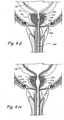
- FIG 1Ashows a sagittal section of a male human body through the lower abdomen showing the male urinary tract.
- the male urinary tractcomprises a pair of tubular organs called ureters (UR) that conduct urine produced by the kidneys.
- the uretersempty into the urinary bladder.
- the urinary bladderis a hollow muscular organ that temporarily stores urine. It is situated posterior to the pubic bone.
- the inferior region of the urinary bladderhas a narrow muscular opening called the bladder neck which opens into a soft, flexible, tubular organ called the urethra.
- the muscles around the bladder neckare called the internal urethral sphincter.
- the internal urethral sphincteris normally contracted to prevent urine leakage.
- the urinary bladdergradually fills with urine until full capacity is reached, at which point the sphincter relaxes. This causes the bladder neck to open, thereby releasing the urine stored in the urinary bladder into the urethra.
- the urethrabegins at the bladder neck, terminates at the end of the penis, and allows for urine to exit the body.
- the region of the urethra just inferior to the urinary bladderis completely surrounded by the prostate gland.
- the prostate glandis part of the male reproductive system and is usually walnut shaped.
- the prostateis divided into lobes.
- the lateral lobesare located lateral to the urethra; the middle lobe is located on the dorsal aspect of the urethra, near the bladder neck.
- the lateral lobesbecome enlarged and act like curtains to close the urethral conduit.
- the middle lobegrows in size and becomes problematic. Because of its superior location near the bladder neck with respect to the urethra, an enlarged middle lobe acts like a ball valve and occludes fluid passage.
- Figure 1Bshows a coronal section through the lower abdomen of a human male showing a region of the male urinary system.
- the prostate gland (PG)is located around the urethra at the union of the urethra and the urinary bladder.
- FIGS 2A through 2Hshow various alternate approaches to deploy implantable tissue compression device(s) (e.g., one or more clips, anchoring elements, tensioning members, etc.) to compress the prostate gland PG, thereby relieving constriction of the urethra.
- implantable tissue compression device(s)e.g., one or more clips, anchoring elements, tensioning members, etc.
- Specific examples of implantable tissue compression device(s) (e.g., one or more clips, anchoring elements, tensioning members, etc.) useable in this inventionare shown in other figures of this patent application and are described more fully herebelow.
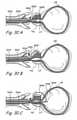
- FIG. 2Ashows a first trans-urethral approach that may be used to implant tissue compression devices(s) to compress the prostate gland PG.
- an introducing device 200is introduced in the urethra through the urethral opening of the penis.
- Introducing device 200comprises an elongate body 202 comprising a lumen that terminates distally in a distal opening 204.
- One or more working device(s) 206is/are then introduced through distal opening 204 into the urethra.
- the working device(s) 206penetrate the urethral wall and thereafter one or more lobes of the prostate gland. In some applications of the method, working device(s) 206 may further penetrate the prostate capsule and enters the pelvic cavity.
- Working device(s) 206are also used to deploy and implant implantable tissue compression device(s) (e.g., one or more clips, anchoring elements, tensioning members, etc.) to compress the prostate gland PG, thereby relieving constriction of the urethra.
- implantable tissue compression device(s)e.g., one or more clips, anchoring elements, tensioning members, etc.
- FIG. 2Bshows a second trans-urethral approach that may be used to implant tissue compression devices(s) to compress the prostate gland PG.
- an introducing device 210is introduced in the urethra through the urethral opening UO of the penis.
- Introducing device 210comprises an elongate body 212 comprising a lumen that terminates distally in a distal opening 214.
- One or more working device(s) 216is/are insertable through distal opening 214 into the urethra.
- Working device(s) 216penetrate(s) the urethral wall inferior to the prostate gland and enters the pelvic cavity.
- working device(s) 216penetrate(s) the prostate capsule CP and thereafter one or more lobes of the prostate gland. In some applications of the method the working device(s) 216 may further penetrate the urethral wall enclosed by the prostate gland EG and enters the urethral lumen. Working device(s) 216 may then be used to deploy and implant implantable tissue compression device(s) (e.g., one or more clips, anchoring elements, tensioning members, etc.) to compress the prostate gland PG, thereby relieving constriction of the urethra.
- implantable tissue compression device(s)e.g., one or more clips, anchoring elements, tensioning members, etc.
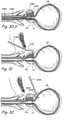
- Figure 2Cshows a third trans-urethral approach that may be used to implant tissue compression devices(s) to compress the prostate gland PG.
- an introducing device 220is introduced in the urethra through the urethral opening UO of the penis.
- Introducing device 220comprises an elongate body 222 comprising a lumen that terminates distally in a distal opening 224.
- Introducing device 220is positioned such that distal opening 224 is located in the urinary bladder UB.
- a one or more working device(s) 226is/are introduced through distal opening 224 into the urinary bladder UB.
- Working device(s) 226penetrate(s) the wall of the urinary bladder UB and thereafter penetrate(s) one or more lobes of the prostate gland PG. In some applications of the method, the working device(s) 226 may further penetrate the prostate capsule and enter the pelvic cavity. Working device(s) 226 may then be used to deploy and implant implantable tissue compression device(s) (e.g., one or more clips, anchoring elements, tensioning members, etc.) to compress the prostate gland PG, thereby relieving constriction of the urethra.
- implantable tissue compression device(s)e.g., one or more clips, anchoring elements, tensioning members, etc.
- Figure 2Dshows a transperineal approach that may be used to implant tissue compression devices(s) to compress the prostate gland PG.
- an introducing device 230is introduced in the pelvic cavity percutaneously through the perineum.
- Introducing device 230comprises an elongate body 232 comprising a lumen that terminates distally in a distal opening 234.
- Introducing device 230is positioned such that distal opening 234 is located in the pelvic cavity adjacent to prostate gland.
- one or more working device(s) 236is/are introduced through distal opening 234 into the prostate gland PG.
- Working device(s) 236penetrate(s) the prostate capsule CP and thereafter penetrate(s) one or more lobes of the prostate gland PG.
- the working device(s) 236may further penetrate the urethral wall surrounded by the prostate gland PG and enter the urethral lumen.
- Working device 236may then be used to deploy and implant implantable tissue compression device(s) (e.g., one or more clips, anchoring elements, tensioning members, etc.) to compress the prostate gland PG, thereby relieving constriction of the urethra.
- implantable tissue compression device(s)e.g., one or more clips, anchoring elements, tensioning members, etc.
- Figure 2Eshows a percutaneous/transvesicular approach that may be used to implant tissue compression devices(s) to compress the prostate gland PG.
- an introducing device 240is introduced percutaneously through the abdominal wall.
- Introducing device 240comprises an elongate body 242 comprising a lumen that terminates distally in a distal opening 244.
- introducing device 240is advanced through the wall of the urinary bladder UB such that distal opening 244 is located in the urinary bladder UB.
- one or more working device(s) 246is/are introduced through distal opening 244 into the urinary bladder UB.
- One ore more working device(s) 246are advanced through the wall of the urinary bladder UB and into the prostate gland PG. In some applications of the method, working device(s) 246 may further penetrate through the prostate gland capsule and enter the pelvic cavity. Working device(s) 246 is/are then used to deploy and implant implantable tissue compression device(s) (e.g., one or more clips, anchoring elements, tensioning members, etc.) to compress the prostate gland PG, thereby relieving constriction of the urethra.
- implantable tissue compression device(s)e.g., one or more clips, anchoring elements, tensioning members, etc.
- Figure 2Fshows a percutaneous trans-osseus approach that may be used to implant tissue compression devices(s) to compress the prostate gland PG.
- an introducing device 250is introduced percutaneously through the abdominal wall.
- Introducing device 250comprises an elongate body 252 comprising a lumen that terminates distally in a distal opening 254.
- Introducing device 250is used to penetrate a pelvic bone (e.g. the pubic bone PB).
- introducing device 250is positioned such that distal opening 254 is located adjacent to the prostate gland PG.
- one or more working device(s) 256is/are introduced through distal opening 254 into the prostate gland PG.
- Working device(s) 256penetrate the prostate capsule and thereafter penetrate one or more lobes of the prostate gland PG. In some applications of the method, working device(s) 256 may further penetrate the urethral wall surrounded by the prostate gland and enter the urethral lumen. Working device(s) 256 is/are then used to deploy and implant implantable tissue compression device(s) (e.g., one or more clips, anchoring elements, tensioning members, etc.) to compress the prostate gland PG, thereby relieving constriction of the urethra.
- implantable tissue compression device(s)e.g., one or more clips, anchoring elements, tensioning members, etc.
- Figure 2Gshows a percutaneous suprapubic approach that may be used to implant tissue compression devices(s) to compress the prostate gland PG.
- an introducing device 260is introduced in the pelvic cavity percutaneously in a trajectory that passes superior to the pubis bone.
- Introducing device 260comprises an elongate body 262 comprising a lumen that terminates distally in a distal opening 264.
- Introducing device 260is then positioned such that distal opening 264 is located in the pelvic cavity adjacent to prostate gland.
- one or more working device(s) 266is/are introduced through distal opening 264 into the prostate gland PG.
- Working device(s) 266penetrate the prostate capsule CP and thereafter penetrate one or more lobes of the prostate gland PG.
- working device(s) 266may further penetrate the urethral wall surrounded by the prostate gland and enter the urethral lumen.
- Working device(s) 266is/are then used to deploy and implant implantable tissue compression device(s) (e.g., one or more clips, anchoring elements, tensioning members, etc.) to compress the prostate gland PG, thereby relieving constriction of the urethra.
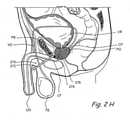
- Figure 2Hshows a percutaneous infrapubic approach that may be used to implant tissue compression devices(s) to compress the prostate gland.
- an introducing device 270is introduced in the pelvic cavity percutaneously in a trajectory that passes inferior to the pubis bone.
- Introducing device 270comprises an elongate body 272 comprising a lumen that terminates distally in a distal opening 274.
- Introducing device 270is introduced percutaneously in the pelvic cavity in a trajectory that passes inferior to the pubic bone.
- Introducing device 270is then positioned such that distal opening 274 is located in the pelvic cavity adjacent to prostate gland.
- one or more working device(s) 276is/are introduced through distal opening 274 into the prostate gland PG.
- Working device(s) 276penetrate the prostate capsule CP and thereafter penetrate one or more lobes of the prostate gland PG. In some applications of the method, working device(s) 276 may further penetrate the urethral wall surrounded by the prostate gland PG and enter the urethral lumen.
- Working device(s) 276is/are then used to deploy and implant implantable tissue compression device(s) (e.g., one or more clips, anchoring elements, tensioning members, etc.) to compress the prostate gland PG, thereby relieving constriction of the urethra.
- implantable tissue compression device(s)e.g., one or more clips, anchoring elements, tensioning members, etc.
- Figure 21shows a trans-rectal approach that may be used to implant tissue compression devices(s) to compress the prostate gland PG.
- an introducing device 280is introduced in the rectum.
- Introducing device 280comprises an elongate body 282 comprising a lumen that terminates distally in a distal opening 284.
- Introducing deviceis then advanced such that it penetrates the rectal wall and enters the pelvic cavity.
- Introducing device 280is then positioned such that distal opening 284 is located in the pelvic cavity adjacent to prostate gland.
- one or more working device(s) 286is/are introduced through distal opening 284 into the prostate gland PG.
- Working device(s) 286penetrate the prostate capsule CP and thereafter penetrate one or more lobes of the prostate gland.
- working device(s) 286may further penetrate the urethral wall surrounded by the prostate gland and enter the urethral lumen.
- Working device(s) 286is/are then used to deploy and implant implantable tissue compression device(s) (e.g., one or more clips, anchoring elements, tensioning members, etc.) to compress the prostate gland PG, thereby relieving constriction of the urethra.
- implantable tissue compression device(s)e.g., one or more clips, anchoring elements, tensioning members, etc.
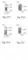
- Figures 3A to 3Fshow various examples of devices and systems that are useable to treat conditions where the prostate gland PG is compressing a region of the urethra such that the urethra does not expand normally during micturition and urine outflow is impeded..
- Figure 3Ashows the perspective view of an introducer device 300.
- Introducer device 300comprises an outer body 301 constructed from suitable biocompatible materials including, but not limited to Pebax, Polyimide, Braided Polyimide, Polyurethane, Nylon, PVC, Hytrel, HDPE, PEEK, metals like stainless steel and fluoropolymers like PTFE, PFA, FEP, EPTFE etc.
- Body 301comprises a working device lumen 302. Distal end of working device lumen 302 emerges out of the distal end of body 301. In one example, distal end of working device lumen 302 has a bent or curved region. Proximal end of working device lumen 302 emerges out of a first flexible tube 304. The proximal end of first flexible tube 304 comprises a stasis valve 306.
- Body 301further comprises a cystoscope lumen 308. Distal end of cystoscope lumen 308 emerges out of the distal end of body 301.
- cystoscope lumen 308emerges out of a second flexible tube 310.
- the proximal end of second flexible tube 310comprises a stasis valve 312.
- Cystoscope lumen 308may comprise one or more side ports e.g. a first side port 318 for the introduction or removal of one or more fluids.
- Working device lumen 302may comprise one or more side ports e.g. a second side port 320 for the introduction or removal of one or more fluids.
- Figure 3Bshows a perspective view of an injecting needle.
- Injecting needle 330is used for injecting one or more diagnostic or therapeutic substances.
- the injecting needle 330may be used to inject local anesthetic in the urethra, prostate gland and/or tissues near the prostate gland.
- target areas for injecting local anestheticsare the neurovascular bundles, the genitourinary diaphragm, the region between the rectal wall and prostate, etc.
- Examples of local anesthetics that can be injected by injecting needle 330are anesthetic solutions e.g. 1 % lidocaine solution; anesthetic gels e.g. lidocaine gels; combination of anesthetic agents e.g.
- Injecting needle 330comprises a hollow shaft 332 made of suitable biocompatible materials including, but not limited to stainless steel 304, stainless steel 306, Nickel-Titanium alloys, titanium etc.
- the distal end of hollow shaft 332comprises a sharp tip 334.
- the proximal end of hollow shaft 332has a needle hub 336 made of suitable biocompatible materials including, but not limited to metals e.g. stainless steel 304, stainless steel 306, Nickel-Titanium alloys, titanium etc.; polymers e.g.
- needle hub 336comprises a luer lock.
- FIG. 3Cshows an example of an introducing device or introducing sheath 340.
- Introducing sheath 340comprises a hollow, tubular body 342 made of suitable biocompatible materials including, but not limited to metals e.g. stainless steel 304, stainless steel 306, Nickel-Titanium alloys, titanium etc. or polymers e.g. Pebax, Polyimide, Braided Polyimide, Polyurethane, Nylon, PVC, Hytrel, HDPE, PEEK, PTFE, PFA, FEP, EPTFE etc.
- Tubular body 342further comprises two marker bands: a proximal marker band 344 and a distal marker band 346. The marker bands can be seen by a cystoscope.
- proximal marker band 344 and distal marker band 346are radiopaque.
- the position of proximal marker band 344 and distal marker band 346is such that after introducing sheath 340 is placed in an optimum location in the anatomy, proximal marker band 344 is located in the urethra where it can be seen by a cystoscope and distal marker band 346 is located in the prostrate gland or in the wall of the urethra where it cannot be seen by a cystoscope.
- Tubular body 342further comprises a series of distance markers 348 on the outer surface of tubular body 342.
- the proximal end of tubular body 342further comprises a hub 350 made of suitable biocompatible materials including, but not limited to metals e.g.
- hub 350comprises a luer lock.
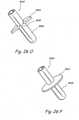
- FIG. 3Dshows a perspective view of a trocar.
- Trocar 360comprises a tubular trocar body 362.
- the proximal end of trocar body 362comprises a hub 364.
- Trocar body 362 and hubcan be constructed from suitable biocompatible materials including, but not limited to metals e.g. stainless steel 304, stainless steel 306, Nickel-Titanium alloys, titanium etc. or polymers e.g. Pebax, Polyimide, Braided Polyimide, Polyurethane, Nylon, PVC, Hytrel, HDPE, PEEK, PTFE, PFA, FEP, EPTFE etc.
- Distal end of trocar body 362ends in a sharp trocar tip 366.
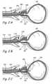
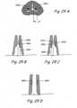
- Anchor delivery device 370comprises a body 372 having a distal opening 373. A section of the distal region of body 372 has been removed to show a view of the anchor assembly.
- Body 372encloses a distal anchor 374 and a proximal anchor 376.
- Proximal anchor 376 and distal anchor 374can have a variety of designs including, but not limited to the designs disclosed elsewhere in this patent application.
- Proximal anchor 376 and distal anchor 374can be constructed from suitable biocompatible materials including, but not limited to metals e.g. stainless steel 304, stainless steel 306, Nickel-Titanium alloys, titanium etc. or polymers e.g.
- proximal anchor 9976 and distal anchor 9974comprise splayable elements that expand in a radially outward direction when a radial compression force, as enacted by body lumen 9972, on proximal anchor 9976 and distal anchor 9974 is removed.
- the splayable elementscan be made of suitable super-elastic materials such as Nickel-Titanium alloys etc.
- Proximal anchor 9976 and distal anchor 9974are connected to each other by a tension element 9978.
- Tension element 9978can be made of suitable elastic or non-elastic materials including, but not limited to metals e.g. stainless steel 304, stainless steel 306, Nickel-Titanium alloys, suture materials, titanium etc. or polymers such as silicone, nylon, polyamide, polyglycolic acid, polypropylene, Pebax, PTFE, ePTFE, silk, gut, or any other braided or mono-filament material.
- Tension element 9978can have a variety of designs including the designs shown in figures 5A through 5F . As shown in Figure 3E , the proximal end of proximal anchor 9976 is connected by an attachment mechanism 9980 to a torquable shaft 9982.
- control button 9984can be used to deploy proximal anchor 9976 by sliding control button 9984 along groove 9985 in the distal direction. Control button 9984 is then used to deploy distal anchor 9974 by turning control button 9984 in the circumferential direction along groove 9985.
- FIG. 3Hshows a perspective view from the proximal direction of a particular embodiment of the attachment mechanism of figure 3E .
- Attachment mechanism 380comprises a circular plate 386 made from suitable biocompatible materials including, but not limited to metals e.g. stainless steel 304, stainless steel 306, Nickel-Titanium alloys, titanium etc. or polymers e.g. Polycarbonate, PVC, Pebax, Polyimide, Polyurethane, Nylon, Hytrel, HDPE, PEEK, PTFE, PFA, FEP etc.
- the proximal face of circular plate 386is connected to torquable shaft 382.
- Circular plate 386further comprises a semicircular groove 388. One end of semicircular groove 388 comprises an enlarged region 390.
- a knob 392 located on the proximal portion of proximal anchor 376slides on semicircular groove 388.
- the size of knob 322is larger than the size of semicircular groove 388 but smaller than size of enlarged region 390. This keeps proximal anchor 376 attached to circular plate 386.
- control button 384is turned in the circumferential direction along groove 385, torquable shaft 382 is turned. This turns circular plate 386 causing knob 392 to slide on the groove 388.
- knob 392reaches enlarged region 390. This releases knob 392 from circular plate 386 thereby releasing proximal anchor 376 from anchor delivery device 370.
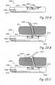
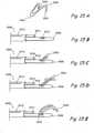
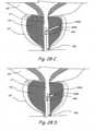
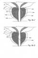
- Figures 4A through 4Hshow a coronal section through the prostate gland showing the various steps of a method of treating prostate gland disorders by compressing a region of the prostate gland using the kit shown in Figures 3A through 3F .
- introducer device 300is introduced in the urethra through the urethral opening at the tip if the penis.
- a cystoscopeis inserted in introducer device 300 through cystoscope lumen 308 such that the lens of the cystoscope is located in the distal opening of cystoscope lumen.
- the cystoscopeis used to navigate introducer device 300 through the urethra such that the distal region of introducer device 300 is located in a target region in the prostatic urethra.
- injecting needle 330is advanced through working device lumen 302 such that the distal tip of injecting needle 330 penetrates into a region of the urethral wall or the prostate gland. Injecting needle 330 is then used to inject one or more diagnostic or therapeutic agents into the urethral wall or the prostate gland. This step may be repeated one or more times to inject one or more diagnostic or therapeutic agents in one or more regions of the urethral wall and/or the prostate gland. In one method, injecting needle 330 is used to inject an anesthetic in one or more regions of the urethral wall and/or the prostate gland. In another example method, injecting needle 330 is used to deliver energy in the form of radiofrequency energy, resistive heating, laser energy, microwave energy etc.
- injecting needle 330is used to deliver alpha antagonist agents, such as phenoxybenzamine, prazosin, doxazosin, terazosin, tamsulosin, alfuzosin etc.
- injecting needle 330is used to deliver anti-androgen, such as flutamide or 5-alpha reductase inhibitors, such as finasteride, dutasteride, 3-oxosteroid compounds, 4-aza-3-oxosteroid derivatives of testosterone etc.
- injecting needle 330is used to deliver anti-inflammatory agents, such as rapamycin, paclitaxel, ABT-578, everolimus, taxol etc.
- injecting needle 330is used to deliver ablative agents such as methyl alcohol etc.
- injecting needle 330is used to deliver energy in the form of radiofrequency energy, resistive heating, laser energy, microwave energy etc.
- injecting needle 330is used to deliver alpha antagonist agents, such as phenoxybenzamine, prazosin, doxazosin, terazosin, tamsulosin, alfuzosin etc.
- injecting needle 330is used to deliver anti-androgen, such as flutamide or 5-alpha reductase inhibitors, such as finasteride, dutasteride, 3-oxosteroid compounds, 4-aza-3-oxosteroid derivatives of testosterone etc.
- injecting needle 330is used to deliver anti-inflammatory agents, such as rapamycin, paclitaxel, ABT-578, everolimus, taxol etc.
- injecting needle 330is used to deliver ablative agents such as methyl alcohol etc.
- step 4Cinjecting needle 330 is withdrawn from introducer device 300.
- introducer sheath 340 and trocar 360are advanced through working device lumen 302.
- introducer sheath 340 and trocar 360are advanced till the distal tip of trocar 360 penetrates the capsule of the prostate gland and the distal end of introducer sheath 340 is located outside the prostate gland in the pelvic cavity.
- trocar 360is withdrawn from working device lumen 302 leaving introducer sheath 340 in place.
- anchor delivery device 370is introduced through the lumen of introducer sheath 340 till the distal end of body 372 protrudes through the distal tip of introducer sheath 340.
- distal anchor 374is deployed. It should be noted that the anchor may be carried to the site and deployed from within an introducer, on the outside of an introducer, or it may be the distal tip of the introducer itself. Thereafter, anchor deliver device 370 is pulled in the proximal direction along with introducer sheath 340 so that distal anchor 374 is anchored on the outer surface of the prostate capsule. This step may be used to create tension in the tension element 378. In one method, anchor deliver device 370 is pulled in the proximal direction along with introducer sheath 340 such that the distal end of anchor delivery device 370 is located in the prostate gland.
- anchor deliver device 370is pulled in the proximal direction along with introducer sheath 340 till the distal end of anchor delivery device 370 is located in the urethral wall or the urethral lumen.
- proximal anchor 376is deployed. Proximal anchor 376 may be deployed in the prostate gland, in the urethral wall or in the urethral lumen. Proximal anchor 376 is still attached by attachment mechanism 380 to anchor delivery device 370. The proximal anchor may be pre-loaded on the tension element, or may subsequently be loaded by the operator on the tension element.
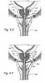
- Figures 4G through 4Hshow the steps of deploying proximal anchor 376 in the prostate gland.
- proximal anchor 376is separated from anchor delivery device 370. This separation may be achieved via numerous means including cutting, melting, un-locking a link, or breaking the tensioning element at a desired location. Ideally this residual end of the tensioning element will not protrude substantially into the lumen of the urethra. Thus proximal anchor 376 and distal anchor 374 are anchored in the anatomy. Thereafter, anchor delivery device 370 and introducer sheath 340 are both pulled in the proximal direction and are withdrawn into introducer device 300. Thereafter, introducer device 300 is pulled in the proximal direction to pull it out of the urethra. In Figure 4H , the steps from Figure 4A through 4G are repeated in a second region of the prostate gland if desired to implant two or more sets of anchoring devices.
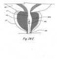
- Figures 4G' through 4H'show the steps of deploying proximal anchor 376 in the urethra.
- proximal anchor 376is separated from anchor delivery device 370 in the urethra.
- proximal anchor 376 and distal anchor 374are anchored in the urethra and the prostate capsule respectively.
- anchor delivery device 370 and introducer sheath 340are both pulled in the proximal direction and are withdrawn into introducer device 300.
- introducer device 300is pulled in the proximal direction to pull it out of the urethra.
- Figure 4Hshows a coronal section through the prostate gland showing the final deployed configuration of an example of bone anchoring devices for treating prostate gland disorders by compressing a region of the prostate gland.
- introducer sheath 340 and trocar 360are advanced till the distal tip of trocar 360 penetrates a bone in the abdomen (e.g. the pelvic bone, etc.) and the distal end of introducer sheath 340 is located outside the bone.
- trocar 360is withdrawn from working device lumen 302 leaving introducer sheath 340 in place.
- anchor delivery device 370is introduced through the lumen of introducer sheath 340 until the distal end of body 372 touches the bone through the distal tip of introducer sheath 340.
- distal anchor 374is implanted in the bone.
- Distal anchor 374may comprise a variety of designs including, but not limited to designs of distal tips of Kirschner wires. Examples of such Kirschner wire distal tips are spiral drill tips, lancer tips, threaded trocar tips, lengthwise knurled tips, 3-sided trocar tips, 4-sided trocar tips,
- anchor deliver device 370is pulled in the proximal direction along with introducer sheath 340. This step creates tension in the tension element 378.
- anchor deliver device 370is pulled in the proximal direction along with introducer sheath 340 till the distal end of anchor delivery device 370 is located in the urethral wall or the urethral lumen.
- the remaining method stepsare similar to steps 4F through 4H.
- One or more anchors disclosed in this patent applicationmay be implanted in anatomical locations that include, but are not limited to:
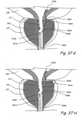
- Figures 4I and 4Jshow a crossection of the urethra through the prostate gland PG showing the appearance of the urethral lumen before and after performing the method shown in Figures 4A through 4H .
- Figure 4Ishows a crossection of the urethra through the prostate gland showing the appearance of the urethral lumen in a patient with BPH.
- Figure 4Jshows a crossection of the urethra through the prostate gland PG showing the appearance of the urethral lumen after performing the procedure shown in Figures 4A through 4H .
- the urethral lumen shown in Figure 4Iis larger than the urethral lumen in Figure 4J .
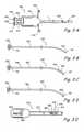
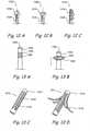
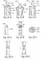
- Figures 5A through 5Fshow perspective views of some designs of the tension elements that can be used in the embodiments disclosed elsewhere in this patent application.
- Figure 5Ashows a perspective view of a tension element 500 comprising a single strand of an untwisted material.
- materials that can be used to manufacture tension element 500include but are not limited to synthetic fibers e.g. various grades of Nylon, polyethylene, polypropylene, polyester, Aramid etc.; metals e.g. various grades of stainless steel, titanium, nickel-titanium alloys, cobalt-chromium alloys, tantalum etc.; natural fibers e.g. cotton, silk etc.; rubber materials e.g. various grades of silicone rubber etc.
- Figure 5Bshows a perspective view of a tension element 502 comprising one or more serrations 504 or notches. Serrations 504 may be aligned in a particular direction to allow relatively easy movement of an outer body along tension element 502 in one direction and offer significant resistance to movement of the outer body along the tension element in the other direction.
- Figure 5Cshows a perspective view of a tension element 506 comprising multiple filaments 507 of a material twisted together. Examples of materials that can be used include to manufacture multiple filaments 507 include but are not limited to synthetic fibers e.g. various grades of Nylon, polyethylene, polypropylene, polyester, Aramid etc.; metals e.g.
- FIG. 5Dshows a perspective view of a tension element 509 comprising a flexible, elastic, spiral or spring element.
- tension element 509examples include but are not limited to metals e.g. various grades of stainless steel, titanium, nickel-titanium alloys, cobalt-chromium alloys, tantalum etc.
- Figure 5Eshows a perspective view of a tension element 510 comprising a screw threading 511 on the outer surface of tension element 510. Screw threading 511 enables tension element 510 to be screwed through an outer element to advance or withdraw tension element through the outer element.
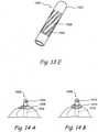
- Figure 5Fshows a perspective view of a tension element 512 comprising a hollow shaft 514 comprising one or more collapsible regions 516.
- a collapsible region 516comprises one or more windows 518.
- Windows 518are cut in hollow shaft 514 in such a way that several thin, collapsible struts 520 are created between adjacent windows 518.
- tension element 512is compresses along its length, collapsible struts 520 are deformed in the radially outward direction to create one or more anchoring regions.
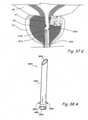
- Figure 5Gshows a perspective view of an anchoring device 522 comprising a tension element and two anchors. Distal end of a tension element 524 is attached to a distal anchor 526. Proximal end of tension element 524 is attached to a proximal anchor 528.
- Figure 5Hshows a perspective view of a tensioning element device comprising a detachable region.
- Anchoring device 530comprises a first anchor 532 and a second anchor 534.
- First anchor 532 and second anchor 534may comprise a variety of anchor designs disclosed elsewhere in this patent application.
- one or both of first anchor 532 and second anchor 534comprise a substantially flat plate.
- the substantially flat platemay be made from various materials including, but not limited to metals e.g. various grades of stainless steel, titanium, nickel-titanium alloys, cobalt-chromium alloys, tantalum etc.; polymers e.g. polypropylene, Teflon etc.; synthetic fibers e.g.
- First anchor 532 and second anchor 534are connected to a tensioning element.
- the tensioning elementcomprises two flexible members: a first tensioning member 536 and a second tensioning member 538.
- the distal end of first tensioning member 536is connected to first anchor 532 and the proximal end of second tensioning member 538 is connected to second anchor 534.
- Proximal end of first tensioning member 536 and distal end of second tensioning member 538are connected to a releasable member 540.
- Releasable member 540can be releasably connected to a deploying device.
- first anchor 532is deployed out of an anatomical tissue (e.g. the prostate gland) into a first anatomical cavity (e.g. the pelvic cavity).
- second anchor 534is deployed into a second anatomical cavity (e.g. the urethral lumen).
- releasable member 540is released from the deploying device to deliver anchoring device 530 in a target region.
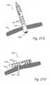
- FIG. 5Ishows a perspective view of a tensioning element comprising telescoping tubes.
- Tensioning element 544may comprise two or more telescoping tubes.
- tensioning element 544comprises three telescoping tubes: a first telescoping tube 546, a second telescoping tube 548 and a third telescoping tube 550.
- Second telescoping tube 548slidably fits into a lumen of first telescoping tube 546.
- third telescoping tube 550slidably fits into a lumen of second telescoping tube 548.
- the telescoping tubeshave a locking mechanism to prevent a telescoping tube from completely disengaging from another telescoping tube.
- the telescoping tubesmay be made from a variety of biocompatible materials including, but not limited to plastics, metals etc.
- All the components of the systems disclosed hereinmay be coated or embedded with therapeutic or diagnostic substances (e.g., drugs or therapeutic agents) or such therapeutic or diagnostic substances may be introduced into or near the prostate or adjacent tissue through a catheter, cannula needles, etc.
- therapeutic or diagnostic substancese.g., drugs or therapeutic agents
- therapeutic and diagnostic substancesinclude but are not limited to: hemostatic agents; antimicrobial agents (antibacterials, antibiotics, antifungals, antiprotozoals; antivirals; antimicrobial metals (e.g., silver, gold, etc.); hemostatic and/or vasoconstricting agents (e.g., pseudoephedrine, xylometazoline, oxymetazoline, phenylephrine, epinephrine, cocaine, etc.); local anesthetic agents (lidocaine, cocaine, bupivacaine, ); hormones;anti-inflammatory agents (steroidal and non-steroidal); hormonally active agents; agents to enhance potency; substances to dissolve, degrade, cut, break, weaken, soften, modify or remodel connective tissue or other tissues; (e.g., enzymes or other agents such as collagenase (CGN), trypsin, trypsin/EDTA, hyaluronidase, and tosy
- CGNcollagenase
- antitumor agentse.g., cancer chemotherapeutic agents, biological response modifiers, vascularization inhibitors, hormone receptor blockers, cryotherapeutic agents or other agents that destroy or inhibit neoplasia or tumorigenesis
- alkylating agents or other agents which directly kill cancer cells by attacking their DNAe.g., cyclophosphamide, isophosphamide
- nitrosoureas or other agents which kill cancer cells by inhibiting changes necessary for cellular DNA repaire.g., carmustine (BCNU) and lomustine (CCNU)
- antimetabolites and other agents that block cancer cell growth by interfering with certain cell functionsusually DNA synthesis (e.g., 6 mercaptopurine and 5-fluorouracil (5FU), antitumor antibiotics and other compounds that act by binding or intercalating DNA and preventing RNA synthesis (e.g., doxorubicin, daunorubicin, epirubicin
- biological response modifierse.g., interferon, bacillus calmette-guerin (BCG), monoclonal antibodies, interluken 2, granulocyte colony stimulating factor (GCSF), etc.
- PGDF receptor antagonistsherceptin, asparaginase, busulphan, carboplatin, cisplatin, carmustine, cchlorambucil, cytarabine, dacarbazine, etoposide, flucarbazine, flurouracil, gemcitabine, hydroxyurea, ifosphamide, irinotecan, lomustine, melphalan, mercaptopurine, methotrexate, thioguanine, thiotepa, tomudex, topotecan, treosulfan, vinblastine, vincristine, mitoazitrone, oxaliplatin, procarbazine, streptocin,
- BCGbacillus calmette-guerin
- the substances deliveredmay include cells (mucosal cells, fibroblasts, stem cells or genetically engineered cells) as well as genes and gene delivery vehicles like plasmids, adenoviral vectors or naked DNA, mRNA, etc. injected with genes that code for anti-inflammatory substances, etc., and, as mentioned above, macrophages or giant cells that modify or soften tissue when so desired, cells that participate in or effect the growth of tissue.
- Figures 6A through 11Ashow various examples of anchor designs and/or anchoring device designs.
- Figures 6A and 6Bshow examples of a crumpling anchor 600.
- crumpling anchor 600comprises a substantially flattened body 602.
- Body 602can be made of a variety of materials including, but not limited to synthetic fibers e.g. various grades of Nylon, polyethylene, polypropylene, polyester, Aramid etc.; metals e.g. various grades of stainless steel, titanium, nickel-titanium alloys, cobalt-chromium alloys, tantalum etc.; natural fibers e.g. cotton, silk etc.; rubber materials e.g. various grades of silicone rubber etc.
- any or all of the anchors, the tensioning element(s) and any other componentsmay be coated, impregnated, embedded or otherwise provided with substance(s) (e.g., drugs, biologics, cells, etc.) to reduce the likelihood of infection, inflammation, treat the prostatic adenoma directly or enhance the likelihood of endothelialization, deter adhesion formation, promote healing or otherwise improve the likelihood or degree of success of the procedure.
- substance(s)e.g., drugs, biologics, cells, etc.
- Such substance(s)may be released primarily at the time of delivery or may be released over a sustained period. Examples of such substances are listed above and include but are not limited to certain metals with bacteriostatic action (i.e.
- Body 602may be non-woven or woven. Body 602 may have a variety of shapes including, but not limited to square, rectangular, triangular, other regular polygonal, irregular polygonal, circular etc. Body 602 may have a substantially one dimensional, two dimensional or three dimensional shape. The material chosen for this device may have hemostatic properties to reduce bleeding from the implantation tract or site.
- Body 602further comprises one or more attachment means 606. Attachment means are used to create a channel in the body 602 through which tension element 604 passes.
- Crumpling anchor 600is introduced through a region of tissue (e.g. through prostate gland tissue) into a cavity or lumen e.g. pelvic cavity, urethral lumen etc.
- tension element 604is pulled in the proximal direction. The causes crumpling (e.g., collapsing) of the crumpling anchor 600 between the tissue and the distal end of tension element 604. This process prevents tension element 604 in the tissue and prevents further movement of tension element 604 in the proximal direction.
- FIGs 7A and 7Bshow an example of a deployable anchor 700 in an undeployed configuration and a deployed configuration, respectively.
- This deployable anchor 700comprises one or more anchoring arms 702.
- Anchoring arms 702may be made from a variety of elastic, super-elastic or snape memory materials etc. Typical examples of such materials include but are not limited to metals e.g. stainless steel, titanium, nickel-titanium alloys, cobalt-chromium alloys, tantalum etc.
- Anchoring arms 702are connected to a central hub 704. Central hub in turn is connected to the distal end of a tension element 706.
- anchoring arms 702are folded inside a hollow deploying sheath 708.
- FIG. 7Bdeploying sheath 708 is pulled in the proximal direction. This releases anchoring arms 702 from the distal end of deploying sheath 702. This causes anchoring arms 702 to open in the radially outward direction. Anchor 700 can then anchor to tissue and resist movement of tension element 706 in the proximal direction.
- FIGS 8A and 8Bshow sectional views of an undeployed configuration and a deployed configuration respectively of a "T" shaped deployable anchor.
- Anchor 8110comprises an elongate region 802.
- Elongate region 802may be made from a variety of elastic, super-elastic or shape memory materials etc. Typical examples of such materials include but are not limited to metals e.g. stainless steel, titanium, nickel-titanium alloys, cobalt-chromium alloys, tantalum etc; polymers e.g. polypropylene, Teflon etc.
- Middle section of elongate region 802is connected to the distal end of a tension element 804 to form a "T" shaped anchor.
- middle section of elongate region 802is connected to the distal end of a tension element 804 by a hinge.
- elongate region 802is folded inside a hollow deploying sheath 806. This reduces the undeployed diameter of the distal region of anchor 8110 and also prevents unwanted anchoring of elongate region 802 to tissue.
- deploying sheath 806is pulled in the proximal direction. This releases elongate region 802 from the distal end of deploying sheath 806. This in turn causes elongate region 802 to twist and orient itself perpendicular to the distal end of a tension element 804.
- Anchor 800can then anchor to tissue and resist movement of tension element 804 in the proximal direction.
- Anchoring arms 702 in Figures 7A and 7Bcan have a variety of configurations including, but not limited to configurations shown in Figures 9A through 9D.
- Figure 9Ashows a distal end view of an embodiment of an anchor comprising two triangular arms.
- Anchor 900comprises two anchor arms 902.
- Anchor arms 902can be made of a variety of materials including, but not limited to metals e.g. stainless steel, titanium, nickel-titanium alloys, cobalt-chromium alloys, tantalum etc; polymers e.g. polypropylene, Teflon etc.
- Anchor arms 902are connected to a tension element 904.
- anchor arms 902are connected to a central hub, which in turn is connected to tension element 904.
- Anchor 906comprises four anchor arms 908.
- Anchor arms 908can be made of a variety of materials including, but not limited to metals e.g. stainless steel, titanium, nickel-titanium alloys, cobalt-chromium alloys, tantalum etc; polymers e.g. polypropylene, Teflon etc.
- Anchor arms 908are connected to a tension element 910. In one embodiment, anchor arms 908 are connected to a central hub, which in turn is connected to tension element 910.
- Anchor 912comprises four anchor arms 914.
- Anchor arms 914can be made of a variety of materials including, but not limited to metals e.g. stainless steel, titanium, nickel-titanium alloys, cobalt-chromium alloys, tantalum etc; polymers e.g. polypropylene, Teflon etc.
- Anchor arms 914are connected to a tension element 916.
- anchor arms 914are connected to a central hub, which in turn is connected to tension element 916.
- a layer of porous material 918is located between anchor arms 914. Porous material 918 comprises a plurality of pores that allow for tissue ingrowth.
- Porous material 918may also help to distribute the pressure on anchor arms 914 over a wider area.
- Porous material 918can be made of variety of materials including, but not limited to synthetic fibers e.g. various grades of Nylon, polyethylene, polypropylene, polyester, Aramid etc.; metals e.g. various grades of stainless steel, titanium, nickel-titanium alloys, cobalt-chromium alloys, tantalum etc.; natural fibers e.g. cotton, silk etc.; rubber materials e.g. various grades of silicone rubber etc.
- Porous material 918may be non-woven or woven. Any of the arms or struts in one or more anchoring devices may comprise bent or curved regions.
- Figure 9Dshows a distal end view of an embodiment of an anchor comprising four curved arms.
- Anchor 920comprises four curved anchor arms 922.
- Curved anchor arms 922can be made of a variety of materials including, but not limited to metals e.g. stainless steel, titanium, nickel-titanium alloys, cobalt-chromium alloys, tantalum etc; polymers e.g. polypropylene, Teflon etc.
- Curved anchor arms 922are connected to a tension element 924.
- curved anchor arms 922are connected to a central hub which in turn is connected to tension element 924.
- Figure 10Ashows a distal end view of an anchor comprising a spiral element having a three dimensional shape.
- Anchor 1000comprises a three dimensional spiral element 1002.
- Diameter of spiral element 1002may be substantially constant or may substantially vary along the length of spiral element 1002.
- Spiral element 1002may be made of an elastic, super-elastic or shape memory materials.
- Spiral element 1002may be made of a variety of materials including, but not limited to metals e.g. various grades of stainless steel, titanium, nickel-titanium alloys, cobalt-chromium alloys, tantalum etc.; polymers e.g. polypropylene, Teflon etc.; synthetic fibers e.g.
- Spiral element 1002is connected to a central hub 1004, which in turn is connected to a tension element.
- spiral element 1002is directly connected to a tension element without using central hub 1004.
- Figure 10A'shows a side view of the anchor in Figure 10A.
- Figure 10A'shows anchor 1000 comprising spiral element 1002 connected to central hub 1004 which in turn is connected to a tension element 1006.
- Figure 10Bshows a distal end view of an anchor comprising a spiral element having a two dimensional shape.
- Anchor 1000comprises a two dimensional spiral element 1010.
- Spiral element 1010may be made of an elastic, super-elastic or shape memory materials.
- Spiral element 1010may be made of a variety of materials including, but not limited to metals e.g. various grades of stainless steel, titanium, nickel-titanium alloys, cobalt-chromium alloys, tantalum etc.; polymers e.g. polypropylene, Teflon etc.; synthetic fibers e.g. various grades of Nylon, polyethylene, polypropylene, polyester, Aramid etc.; natural fibers e.g. cotton, silk etc.; rubber materials e.g. various grades of silicone rubber etc.
- Spiral element 1010is connected to a central hub 1012 which in turn is connected to a tension element.
- spiral element 1010is directly connected to a tension element without using central hub 1012.
- Figure 10B'shows a side view of the anchor in Figure 10B.
- Figure 10B'shows anchor 1008 comprising spiral element 1010 connected to central hub 1012 which in turn is connected to a tension element 1014.
- Figure 10Cshows a distal end view of an anchor comprising one or more circular elements.
- anchor 1016comprises an inner circular element 1018 and an outer circular element 1020.
- a series of radial arms or struts 1022connect inner circular element 1018 to outer circular element 1020 and to a central hub 1024.
- Central hub 1024may have a lumen 1026.
- Anchor 1016may be substantially two dimensional or three dimensional.
- Figure 10C'shows a perspective view of the anchor in Figure 10C.
- Figure 10C'shows an anchor 1016 comprising an inner circular element 1018, an outer circular element 1020 and series of radial arms or struts 1022 connecting inner circular element 1018 to outer circular element 1020 and to a central hub 1024.
- Central hub 1024is connected to a tension element.
- FIG. 10Dshows a perspective view of an embodiment of an anchoring device comprising an outer ring.
- Anchor 1040comprises a central hub 1042 and an outer ring 1044.
- central hub 1042acts as a plug to plug an opening in the anatomy to reduce or prevent bleeding or leakage of fluids.
- Central hub 1042is connected to outer ring 1044 by one or more bars or struts 1046.
- central hub 1042is connected to an inner ring 1048 which in turn is connected to outer ring 1044 by one or more bars or struts 1046.
- Central hub 1042further comprises a locking element 1050.
- Locking element 1050comprises a lumen 1052 through which a tension element can slide.
- Anchor 1040may be made from a variety of materials including, but not limited to synthetic fibers e.g. various grades of Nylon, polyethylene, polypropylene, polyester, Aramid etc.; metals e.g. various grades of stainless steel, titanium, nickel-titanium alloys, cobalt-chromium alloys, tantalum etc.; natural fibers e.g. cotton, silk etc.; rubber materials e.g. various grades of silicone rubber etc.
- synthetic fiberse.g. various grades of Nylon, polyethylene, polypropylene, polyester, Aramid etc.
- metalse.g. various grades of stainless steel, titanium, nickel-titanium alloys, cobalt-chromium alloys, tantalum etc.
- natural fiberse.g. cotton, silk etc.
- rubber materialse.g. various grades of silicone rubber etc.
- FIG 10Eshows a partial perspective view of an anchoring device comprising a hemostatic element.
- Anchor 1060comprises a central hub 1062.
- central hub 1062acts as a plug to plug an opening in the anatomy to reduce or prevent bleeding or leakage of fluids.
- Central hub 1062comprises a cinching mechanism to allow central hub 1062 to cinch on to a tension element 1064 passing through central hub 1062.
- the free end 1066 of tension element 1064is severed to minimize the presence of tension element 1064 in the anatomy.
- Anchor 1060further comprises an outer ring 1068.
- Central hub 1062is connected to outer ring 1068 by one or more struts 1070.
- Anchor 1060further comprises a mesh or porous element 1072 between outer ring 1068 and struts 1070.
- the mesh or porous element 1072may be concave shaped as shown in Figure 10E .
- Mesh or porous element 1072allows for tissue ingrowth over a period of time thus providing additional securing of
- Anchoring device 1100may comprise one or more anchors comprising a curved sheet.
- anchoring device 1100comprises a first anchor 1102 and a second anchor 1104.
- First anchor 1102 and second anchor 1104may comprise elastic, super elastic or shape memory materials.
- First anchor 1102 and second anchor 1104may be made from various materials including, but not limited to metals e.g. various grades of stainless steel, titanium, nickel-titanium alloys, cobalt-chromium alloys, tantalum etc.; polymers e.g. polypropylene, Teflon etc.; synthetic fibers e.g.
- first anchor 1102is deployed out of an anatomical tissue (e.g. the prostate gland) into a first anatomical cavity (e.g. the pelvic cavity). Thereafter, second anchor 1104 is deployed into a second anatomical cavity (e.g. the urethral lumen).
- an anatomical tissuee.g. the prostate gland
- first anatomical cavitye.g. the pelvic cavity
- second anchor 1104is deployed into a second anatomical cavity (e.g. the urethral lumen).
- This methodhas the advantage of using the natural curvature of first anchor 1102 and second anchor 1104 to distribute pressure on first anchor 1102 and second anchor 1104 over a large area.
- Figures 12A through 17Ishow further examples of anchor designs and/or anchoring device designs.
- Figure 12Ashows a perspective view of an anchor comprising an arrowhead.
- Anchor 1200comprises an arrowhead 1202.
- Arrowhead 1202may be made from various materials including, but not limited to metals e.g. various grades of stainless steel, titanium, nickel-titanium alloys, cobalt-chromium alloys, tantalum etc.; polymers e.g. polypropylene, Teflon etc.; rubber materials e.g. various grades of silicone rubber etc.
- Arrowhead 1202may comprise a sharp distal tip.
- Arrowhead 1202may have a three dimensional or a substantially two dimensional design.
- Proximal region of arrowhead 1202is wider that the distal region of arrowhead 1202 to resist motion of arrowhead 1202 along the proximal direction after it is deployed in a tissue.
- Proximal region of arrowhead 1202is connected to a tension element 1204.
- Figure 12Bshows a crossectional view of an anchor comprising a cup-shaped element that encloses a cavity.
- Anchor 1208comprises a cup-shaped element 1210.
- Proximal, concave surface of cup-shaped element 1210encloses a cavity.
- Cup-shaped element 1210may be made from various materials including, but not limited to metals e.g.
- FIG. 12Cshows a perspective view of an anchor comprising a screw.
- Anchor 1216comprises a screw 1218.
- Screw 1218may be made from various materials including, but not limited to metals e.g. various grades of stainless steel, titanium, nickel-titanium alloys, cobalt-chromium alloys, tantalum etc.; polymers e.g. polypropylene, Teflon etc.
- Screw 1218may comprise a sharp distal tip. Proximal region of screw 1218 may be wider that the distal region of screw 1218 to resist motion of screw 1218 along the proximal direction after it is deployed in a tissue. Screw 1218 comprises a thread rolled thread including, but not limited to wood screw style thread, double lead thread, tapping style thread, tapered wood thread etc. Proximal region of arrowhead 1202 is connected to a tension element 1204.
- FIG. 13A and 13Bshow perspective views of an uncollapsed state and a collapsed state respectively of an anchor comprising a collapsible region.
- anchor element 1300is in an uncollapsed state.
- Anchor element 1300comprises a hollow shaft 1302 comprising one or more collapsible regions.
- a collapsible regioncomprises one or more windows 1304.
- Windows 1304are cut in hollow shaft 1302 in such a way that several thin, collapsible struts 1306 are created between adjacent windows 1304.
- anchor element 1300is in a collapsed state. When anchor element 1300 is compresses along its length, collapsible struts 1306 are deformed in the radially outward direction to create one or more anchoring regions.
- FIGS 13C and 13Dshow perspective views of an undeployed state and a deployed state respectively of an anchor comprising radially spreading arms.
- anchor 1312comprises a hollow tube 1314.
- Hollow tube 1314is made from suitable elastic, super-elastic or shape memory materials such as metals including, but not limited to titanium, stainless steel, Nitinol etc.; suitable elastic polymers etc.
- U-shaped slots 1316are cut in hollow tube 1314 in such a way that arms 1318 are created within U-shaped slots 1316. In this embodiment, U-shaped slots are substantially parallel to the axis of hollow tube 1314. In absence of an external force, arms 1318 tend to spread in a radially outward direction.
- Anchor 1312is kept in an undeployed state by enclosing anchor 1312 in a sheath. Anchor 1312 is deployed by removing the sheath to allow arms 1318 to spread in a radially outward direction as shown in Figure 13D .
- Hollow tube 1314may comprise one or more cinching elements. Cinching elements may be located on the proximal region, distal region or a middle region of hollow tube 1314.
- the cinching element or elementsmay comprise cinching mechanisms including, but not limited to cinching mechanisms disclosed in figures 26A through 29P .
- FIG 13Eshows perspective views of an alternate embodiment of an undeployed state of an anchor comprising radially spreading arms.
- anchor 1320comprises a hollow tube 1322.
- Hollow tube 1322is made from suitable elastic, super-elastic or shape memory materials such as metals including, but not limited to titanium, stainless steel, Nitinol etc.; suitable elastic polymers etc.
- U-shaped slots 1324are cut in hollow tube 1322 in such a way that arms 1326 are created within U-shaped slots 1324. In this embodiment, U-shaped slots are at an angle to the axis of hollow tube 1322 as shown in Figure 13E .
- Figures 14A and 14Bshow perspective views of anchoring devices comprising an adhesive delivering element.
- Figure 14Ashows a perspective view of an anchoring device 1400 comprising a hollow shaft 1402 with a shaft lumen.
- Hollow shaft 1402can be made of suitable biocompatible materials including, but not limited to Pebax, Polyimide, Braided Polyimide, Polyurethane, Nylon, PVC, Hytrel, HDPE, PEEK, metals like stainless steel and fluoropolymers like PTFE, PFA, FEP and EPTFE etc.
- Distal end of shaft lumenends in a delivery opening 1404. When an adhesive is injected through the shaft lumen, it emerges out of anchoring device 1400 through delivery opening 1404.
- Hollow shaft 1402may also comprise an attachment element 1406 such as a porous woven or non-woven circular sleeve securely attached to hollow shaft 1402.
- the circular sleevemay be made of a variety of materials including, but not limited to metals e.g. various grades of stainless steel, titanium, nickel-titanium alloys, cobalt-chromium alloys, tantalum etc.; polymers e.g. polypropylene, Teflon etc.; synthetic fibers e.g. various grades of Nylon, polyethylene, polypropylene, polyester, Aramid etc.; natural fibers e.g. cotton, silk etc.; rubber materials e.g. various grades of silicone rubber etc.
- FIG 14Bshows a perspective view of an anchoring device 1408 comprising a hollow shaft 1410 with a shaft lumen.
- Hollow shaft 1410can be made of suitable biocompatible materials including, but not limited to Pebax, Polyimide, Braided Polyimide, Polyurethane, Nylon, PVC, Hytrel, HDPE, PEEK, metals like stainless steel and fluoropolymers like PTFE, PFA, FEP and EPTFE etc.
- Distal end of shaft lumenends in a delivery opening 1412. When an adhesive is injected through the shaft lumen, it emerges out of anchoring device 1408 through delivery opening 1412.
- Hollow shaft 1410may also comprise an attachment element 1414 such as porous foam securely attached to hollow shaft 1410.
- the porous foammay be made of a variety of materials including, but not limited to polymers e.g. polypropylene, Teflon etc.; synthetic fibers e.g. various grades of Nylon, polyethylene, polypropylene, polyester, Aramid etc.; rubber materials e.g. various grades of silicone rubber etc.
- the adhesive flowing out through delivery openingcomes into contact with attachment element 1414 and securely attaches attachment element 1414 to surrounding tissue.
- Typical examples of adhesives that can be used with anchoring device 1400 and anchoring device 1408include but are not limited to cyanoacrylates, marine adhesive proteins, fibrin-based sealants etc.
- FIGS 15A and 15Bshow two configurations of an anchoring device comprising a ratcheted tension element.
- Anchoring device 1500comprises a distal anchor.
- Distal anchormay comprise a design selected from the variety of designs disclosed elsewhere in this document.
- distal anchorcomprises a series of radial arms 1502 connected to a central hub 1504. The proximal end of central hub is attached to a ratcheted tension element 1506.
- a proximal anchoris located on ratcheted tension element 1506 proximal to the distal anchor.
- Proximal anchormay comprise a design selected from the variety designs disclosed elsewhere in this document.
- distal anchorcomprises a series of radial arms 1508 connected to a central hub 1510.
- Central hub 8368has a central lumen through which ratcheted tension element 1506 can slide.
- Ratcheted tension element 1506has ratchets arranged such that proximal anchor can slide easily over ratcheted tension element 1506 in the distal direction but cannot slide easily in the proximal direction.
- proximal anchorslides over ratcheted tension element 1506 in the distal direction. This causes a compression of tissue between distal anchor and proximal anchor. The compression of tissue can be maintained since proximal anchor cannot slide easily in the proximal direction.
- distal anchoris introduced via an anatomical lumen (e.g. the urethral lumen) and through a tissue (e.g.
- Anchoring device 1500may be made from various materials including, but not limited to metals e.g. various grades of stainless steel, titanium, nickel-titanium alloys, cobalt-chromium alloys, tantalum etc.; polymers e.g. polypropylene, Teflon etc.
- FIG. 16shows a perspective view of an anchor comprising a trocar lumen.
- Anchor 1600comprises a hollow shaft 1602 comprising a lumen.
- a trocar 1604 or a penetrating devicecan pass through hollow shaft 1602 such that the distal tip of trocar 1604 emerges out through the distal end of hollow shaft 1602.
- Distal end of hollow shaft 1602comprises a tapering region 1606 with a smaller distal diameter and a larger proximal diameter.
- Tapering region 1606further comprises a series of sharp projections 1608 located on the proximal end of tapering region 1606. Projections 1608 may be projecting in the proximal direction, radially outward direction etc.
- Anchor 1600may also comprise a sleeve 1610 located proximal to tapering region 1606.
- Sleeve 1610is made of a porous material that has a plurality of pores that allow for tissue ingrowth thus anchoring sleeve 1610 firmly in tissue.
- Sleeve 1610may also help to distribute the pressure on tapering region 1606 over a wider area.
- Sleeve 1610may be non-woven or woven.
- Sleeve 1610can be made of variety of materials including, but not limited to synthetic fibers e.g. various grades of Nylon, polyethylene, polypropylene, polyester, Aramid etc.; metals e.g. various grades of stainless steel, titanium, nickel-titanium alloys, cobalt-chromium alloys, tantalum etc.; natural fibers e.g. cotton, silk etc.; rubber materials e.g. various grades of silicone rubber etc.
- FIG 17Ashows a perspective view in the undeployed state of an anchor comprising a rigid or partially flexible T element and a crumpling element.
- anchoring device 1700comprises a distal, T element 1702.
- the T element 1702may be made of a variety of materials including, but not limited to metals e.g. various grades of stainless steel, titanium, nickel-titanium alloys, cobalt-chromium alloys, tantalum etc.; polymers e.g. polypropylene, Teflon etc.; rubber materials e.g. various grades of silicone rubber etc. Further it may be a composite material or have cut out sections to allow it to be flexible in certain dimensions but rigid in other dimensions.
- T element 1702is in the form of a hollow cylinder.
- the proximal end of T element 1702is in contact with the distal end of a delivery rod 1704.
- Delivery rod 1704is hollow and is used to deliver T element 8266 in a target anatomical region.
- a trocar 1705can pass through delivery rod 1704 and through T element 1702 such that the distal tip of trocar emerges through the distal end of rigid element 1702.
- the T-elementcould also be contained within a lumen of the trocar or may be the trocar itself. of the T element 1702 is connected to the distal end of a flexible tension element 1706.
- tension element 1706being tied or crimped to the T element, or passing through a loop in the T element, or being adhered by adhesive or weld, or by being made of a continuous material which becomes the T element.
- T elementis shown as a T, any shape which is larger in at least one dimension compared to its other dimensions could appropriately be released and cause to change it's orientation to produce an anchoring effect.
- materials that can be used to manufacture tension element 1706include but are not limited to synthetic fibers e.g. various grades of Nylon, polyethylene, polypropylene, polyester, Aramid etc.; metals e.g.
- a substantially flattened body 1708is located on the distal region of tension element 1706.
- Tension element 1706is threaded through body 1708 in such a way that tension element 1706 can slide through body 1708.
- Body 1708may be non-woven or woven.
- Body 1708can be made of a variety of materials including, but not limited to synthetic fibers e.g. various grades of Nylon, polyethylene, polypropylene, polyester, Aramid etc.; metals e.g.
- Body 1708may have a variety of shapes including, but not limited to square, rectangular, triangular, other regular polygonal, irregular polygonal, circular etc. Body 1708 may have a substantially one dimensional, two dimensional or three dimensional shape.
- Figures 17B and 17Cshow various steps of a method to deploy the anchoring device shown in Figure 17A .
- anchoring device 1700is introduced in an anatomical cavity (e.g. the pelvic cavity) through a tissue (e.g. the prostate gland).
- trocar 1705is withdrawn by pulling trocar 1705 in the proximal direction.
- delivery rod 1704is withdrawn by pulling delivery rod 1704 in the proximal direction.
- tension element 1706is pulled in the proximal direction.
- Tension element 1706in turn pulls T element 1702 in the proximal direction.
- rigid element 1702is pulled against a wall of the tissue (e.g. the prostate gland) but is unable to penetrate the tissue because of its size. This causes body 1708 to crumple because of compression of body 1708 between the wall of the tissue and rigid element 1702. Crumpled body 1708 may be designed to cause tissue ingrowth or epithelialization in body 1708 as well as healing, hemostasis or a more even force distribution.
- FIGS 17D and 17Eshow perspective views of an undeployed and deployed configuration of an anchor comprising a rigid or partially flexible T element with one or more openings or perforations.
- Figure 17Dshows a perspective view of an anchoring device 1720 comprising an anchor 1722.
- Anchor 1722comprises a tubular body.
- the tubular bodymay comprise one or more openings or perforations 1724 in the tubular body. Openings or perforations 1724 increase the flexibility of anchor 1722. This makes it easier to navigate anchoring device 1720 through the anatomy before reaching its target location. Further it enables anchoring device 1720 to be passed through a tight bend in the anatomy or through a delivery device.
- trocar tip 1727Within tubular body of anchor 1722 is trocar tip 1727 that is fixedly attached to tensioning element 1728.
- anchor 1722comprises a lumen.
- a length of the distal end of deployment element 1726passes through the proximal end of the lumen and abuts trocar tip 1727 that enables anchor 1722 to puncture tissue.
- trocar tipis fixedly attached to elongate deployment element 1726 and is retracted fully into element 1729 upon anchor deployment.
- distal tip of deployment device 1726is not exposed through the distal end of anchor 1722.
- Distal end of anchor 1722comprises a sharp tip to enable anchor 1722 to puncture tissue.
- Anchoring element 1720further comprises a tension element 1728 attached to tubular body 1722. In this embodiment, distal end of tension element 1728 attached to the inner surface of the trocar tip 1727.
- Proximal region of tension element 1728passes through deployment element 1726.
- Anchor 1722is deployed by pushing in a distal direction one elongate deployment element 1726, that runs within lumen of anchor 1722 abutting trocar tip 1727 distally, in tandem with another elongate deployment element 1729 that abuts the proximal end of anchor 1722.
- Anchoring device 1720punctures tissue to transport anchor 1722 through a first anatomical location (e.g. a prostate gland) to a second anatomical location (e.g. the pelvic cavity, urethra etc.). Thereafter, deployment element 1726 is withdrawn by pulling deployment element 1726 in the proximal direction. Thereafter, tension element 1728 is pulled in the proximal direction.
- Anchoring device 1720can be made from a variety of materials including, but not limited to metals such as synthetic fibers e.g. various grades of Nylon, polyethylene, polypropylene, polyester, Aramid etc.; metals e.g.
- Tension element 1728may then be connected to any one of the other anchoring elements such as anchor 10D.
- FIGS 17F and 17Gshow perspective views of an undeployed and deployed configuration of an anchor comprising a stent.
- Anchor 1730comprises a self-expanding stent 1732 and a tension element 1734.
- Distal end of tension element 1734is attached to stent 1732.
- distal end of tension element 1734is attached on the mid section of stent 1732.
- Stent 1732may comprise various designs including, but not limited to metallic tube designs, polymeric tube designs, spiral designs, chain-linked designs, rolled sheet designs, single wire designs etc.
- Stent 1732may have an open celled or closed celled structure.
- a variety of fabrication methodscan be used for fabricating stent 1732 including but not limited to laser cutting a metal or polymer element, welding metal elements etc.
- Anchor 1730is introduced through a sheath 1736 into a target anatomy. Thereafter, sheath 1736 is withdrawn. This causes stent 1732 to revert to its natural shape as shown in Figure 17G , and act as an anchor.
- FIGS 17H and 171show perspective views of an undeployed and deployed configuration of an anchor comprising a spring.
- Anchor 1740comprises an elastic spring 1742 and a tension element 1744. Distal end of tension element 1744 is attached to spring 1742. In one embodiment, distal end of tension element 1744 is attached on the mid section of spring 1742.
- a variety of materialscan be used for fabricating spring 1742 including but not limited to metals, polymers, foam type materials, super elastic materials etc.
- a variety of featurescan be added to spring 1742 including but not limited to radiopaque coatings, drug elution mechanisms etc.
- Anchor 1740is introduced through a sheath 1746 into a target anatomy to reduce the profile of spring 1742. Thereafter, sheath 1746 is withdrawn. This causes spring 1742 to revert to its natural shape as shown in Figure 171 and act as an anchor. examples
- Figures 18A through 22Eshow various of mechanisms to deploy one or more anchors.
- Figure 18Ashows a crossection of an anchor deploying mechanism comprising a screw system.
- Figure 18Ashows an anchor deploying mechanism comprising an anchor 1800 comprising an anchor body 1802 and anchoring elements 1804 attached to anchor body 1802.
- Anchor body 1802comprises an inner lumen.
- Inner lumen of anchor body 1802comprises screw threading.
- Anchoring elements 1804may have various designs including, but not limited to anchor designs disclosed elsewhere in this document.
- Anchor body 1802 and anchoring elements 1804may be made of a variety of materials including, but not limited to metals e.g. various grades of stainless steel, titanium, nickel-titanium alloys, cobalt-chromium alloys, tantalum etc.; polymers e.g.
- the anchor deploying mechanismfurther comprises a deploying shaft 1806.
- Distal region of deploying shaft 1806comprises a screw threading such that deploying shaft 1806 can be screwed into anchor body 1802.
- Figure 18Bshows the method of deploying an anchor comprising a screw mechanism.
- Deploying shaft 1 806is rotated to release the distal region of deploying shaft 1806 from anchor body 1802 after positioning anchor 1800 in a desired location.
- Such a mechanismcan be used to deploy one or more anchors. In one example more than one anchors are located on deploying shaft 1806. The anchors can be sequentially deployed by rotating deploying shaft 1806.
- Deploying shaft 1806may be made of a variety of materials including, but not limited to metals e.g. various grades of stainless steel, titanium, nickel-titanium alloys, cobalt-chromium alloys, tantalum etc.; polymers e.g. polypropylene, Teflon etc.
- the anchor deploying mechanismis located inside an outer sheath.
- Figures 19A and 19Bshow a crossectional view of an anchor deploying system comprising an electrolytic detachment element.
- Figure 19Ashows a crossection of an anchor deploying mechanism comprising a deployable anchor 1900.
- Deployable anchor 1900comprises an anchor body 1902 and anchoring elements 1904 attached to anchor body 1902.
- Anchoring elements 1904may have various designs including, but not limited to anchor designs disclosed elsewhere in this document.
- Anchor body 8402 and anchoring elements 8404may be made of a variety of materials including, but not limited to metals e.g. various grades of stainless steel, titanium, nickel-titanium alloys, cobalt-chromium alloys, tantalum etc.; polymers e.g.
- Proximal region of deployable anchor 1900further comprises an electrolyzable element 1906.
- Electrolyzable element 1906is made of a length of metallic wire e.g. steel wire.
- Proximal region of electrolyzable element 1906is electrically connected to a deploying shaft 1908.
- Proximal region of deploying shaft 1908is further connected to a first electrode.
- the anchor deploying systemfurther comprises a second electrode 1910 connected to a bodily region of the patient to be treated.
- the first electrodeis connected to a positive terminal of a power supply and the second electrode is connected to the negative terminal of the power supply to form an electrical circuit.
- Electrical current flowing between electrolyzable element 1906 and second electrode 1910causes metallic ions from electrolyzable element 1906 to dissolve into surrounding anatomy. This causes electrolyzable element 1906 to detach from deploying shaft 1908.
- Figure 20shows a perspective view of an anchor deploying system comprising a looped ribbon.
- the anchor deploying systemcomprises a deployable anchor 2000.
- Deployable anchor 2000comprises an anchor body 2002 and anchoring elements 2004 attached to anchor body 2002.
- Anchoring elements 2004may have various designs including, but not limited to anchor designs disclosed elsewhere in this document.
- Anchor body 2002 and anchoring elements 2004may be made of a variety of materials including, but not limited to metals e.g. various grades of stainless steel, titanium, nickel-titanium alloys, cobalt-chromium alloys, tantalum etc.; polymers e.g. polypropylene, Teflon etc.; rubber materials e.g. various grades of silicone rubber etc.
- Proximal region of deployable anchor 2000further comprises a looping lumen 2006.
- a looped ribbon 2008is looped through looping lumen 2006.
- Looped ribbon 2008may be made of a variety of materials including, but not limited to synthetic fibers e.g. various grades of Nylon, polyethylene, polypropylene, polyester, Aramid etc.; metals e.g. various grades of stainless steel, titanium, nickel-titanium alloys, cobalt-chromium alloys, tantalum etc.; natural fibers e.g. cotton, silk etc.; rubber materials e.g. various grades of silicone rubber etc.
- looped ribbon 2008extends to a proximal region where it can be cut by a user.
- looped ribbon 2008In a method of deploying deployable anchor 2000, a single cut is made in looped ribbon 2008 at a proximal region. This turns looped ribbon 2008 into a straight ribbon. The straight ribbon can then be pulled in the proximal direction to remove it from deployable anchor 2000. Looped ribbon 2008 may also be in the form of a looped monofilament or multifilament wire or suture.
- Figures 21Ashows a crossectional view of an anchor deploying system comprising a locked ball.
- the anchor deploying systemcomprises a deployable anchor 2100.
- Deployable anchor 2100comprises an anchor body 2102.
- Deployable anchor 2100may have various designs including, but not limited to anchor designs disclosed elsewhere in this document.
- Proximal end of anchor body 2102is connected to a thin shaft 2104.
- Proximal end of thin shaft 2104comprises a locking ball 2106.
- Anchor body 8428, thin shaft 2104 and locking ball 2106may be made of a variety of materials including, but not limited to metals e.g. various grades of stainless steel, titanium, nickel-titanium alloys, cobalt-chromium alloys, tantalum etc.; polymers e.g.
- the anchor deploying systemfurther comprises an outer locking sheath 2108. Distal end of locking sheath 2108 comprises an opening 2110. Diameter of opening 2110 is greater than the diameter of thin shaft 2104 but greater than diameter of locking ball 2106. Thus, locking ball 2106 is locked in locking sheath 2108.
- the anchor deploying systemfurther comprises a deploying shaft 2112 located within locking sheath 2108. Deploying shaft 2112 can be pushed in the distal direction within locking sheath 2108 by a user. Locking sheath 2108 and deploying shaft 2112 may be made of a variety of materials including, but not limited to metals e.g.
- distal region of locking sheath 2108comprises one or more longitudinal grooves or windows to allow distal region of locking sheath 2108 to expand easily in the radial direction.
- Figures 21B and 21Cshow a method of deploying an anchor comprising a locked ball.
- deploying shaft 2112is pushed in the distal direction by a user. This causes distal end of deploying shaft 2112 to push locking ball 2106 in the distal direction. This in turn causes locking ball 2106 to exert a force on the distal end of locking sheath 2108. This force causes opening 2110 to enlarge and release locking ball 2106.
- locking ball 2106is released by locking sheath 2108 thus releasing deployable anchor 2100.
- Figures 22A through 22Cshow various views of an anchor deploying system comprising two interlocking cylinders.
- the anchor deploying systemcomprises a proximal interlocking cylinder and a distal interlocking cylinder.
- the distal interlocking cylinderis located on an anchor to be deployed.
- Figure 22Ashows a perspective view of a proximal interlocking cylinder 2200 comprising a locking element 2202 located on the distal end of proximal interlocking cylinder 2200.
- locking element 2202comprises a solid cylinder with a ninety degree bend.
- Proximal interlocking cylinder 2200 and locking element 2202may be made of a variety of materials including, but not limited to metals e.g.
- Figure 22Bshows a crossectional view of the anchor deploying system comprising proximal interlocking cylinder 2200 interlocked with a distal interlocking cylinder 2204.
- Distal interlocking cylinder 2204comprises a groove 2206 which locks locking element 2202.
- Locking element 2202can be unlocked from distal interlocking cylinder 2204 by turning proximal interlocking cylinder 2200.
- distal interlocking cylinder 2204may be made of a variety of materials including, but not limited to metals e.g.
- Figure 22Cshows a crossectional view through plane A-A in Figure 22B.
- Figure 22Cshows distal interlocking cylinder comprising groove 2206.
- locking element 2202located in groove 2206.
- proximal interlocking cylinder 2200turns locking element 2202.
- distal region of locking element 2202can pass easily through groove 2206 unlocking proximal interlocking cylinder 2200 from distal interlocking cylinder 2204.
- Figures 22D and 22Eshow the steps of a method of unlocking the two interlocking cylinders from the anchor deploying systems of Figures 22A through 22C .
- locking element 2202 of proximal interlocking cylinder 2200is locked in groove 2206 of distal interlocking cylinder 2204.
- proximal interlocking cylinder 2200is turned in a clockwise or counterclockwise direction to unlock locking element 2202 from groove 2206. Thereafter, proximal interlocking cylinder 2200 is pulled in the proximal direction to separate proximal interlocking cylinder 2200 from distal interlocking cylinder 2204.
- FIG. 23Ashows a perspective view of a distal end of an anchoring device that has an imaging modality.
- Anchoring device 2300comprises an elongate shaft 2302 comprising a lumen.
- Elongate shaft 2302can be made of suitable biocompatible materials such as metals, polymers etc.
- the lumen of shaft 2302terminates in a window 2304 located on the distal region of shaft 2302.
- Anchoring devicefurther comprises an imaging modality such as a cystoscope, an ultrasound imaging system etc.
- the imaging modalityis a cystoscope 2306.
- Distal end of cystoscope 2306is located in window 2304 to allow visualization of the anatomy adjacent to window 2304.
- cystoscope 2306is permanently fixed to anchoring device 2300.
- cystoscope 2306can be introduced through the proximal region of anchoring device 2300.
- Anchoring device 2300further comprises a puncturing device 2308. Puncturing device 2308 comprises a sharp distal tip and a lumen that holds an anchor.
- Anchoring device 2300further comprises an anchor deployment device 2310. Distal end of anchor deployment device 2310 is detachably attached to the anchor.
- FIGs 23B through 23Gshow various steps of a method for compressing an anatomical region using the anchoring device of Figure 23A .
- Anchoring device 2300is introduced in an anatomical region such that distal end of anchoring device 2300 is located adjacent to a target anatomical region to be treated.
- anchoring device 2300is introduced transurethrally into the prostatic urethra.
- puncturing device 2308is advanced to puncture the anatomical region.
- puncturing device 2308punctures the prostate gland PG such that distal end of puncturing device 2308 is located in the pelvic cavity. Puncturing device comprises an anchor located in the lumen of puncturing device 2308.
- the anchorcomprises a distal anchor 2312, a tension element 2314 connected at one end to distal anchor 2312 and a proximal anchor 2316 that can slide over tension element 2314.
- Puncturing device 2308comprises a groove at the distal end such that tension element exits puncturing device 2308 through the groove. Puncturing device 2308 further comprises a pusher 2318 that can push distal anchor 2312 out of puncturing device 2308.
- Proximal anchor 2316is detachably attached to the distal region of anchor deployment device 2310.
- Proximal anchor 2312, distal anchor 2316 and tension element 2314may comprise designs including, but not limited to the designs disclosed elsewhere in this patent application.
- the imaging modalitymay be used to verify the accurate placement and working of anchoring device 2300.
- Step 23Cpusher 2318 is pushed in the distal direction to push distal anchor 2312 out of puncturing device 2308.
- Distal anchor 2312is thus deployed in the anatomy e.g. in the pelvic cavity surrounding the prostate gland PG.
- Puncturing device 2308is withdrawn by pulling it in the proximal direction.
- step 23Etension element 2314 is pulled in the proximal direction through anchor deployment device 2310.
- step 23Ftension element 2314 is pulled further in the proximal direction such that the anatomical region between proximal anchor 2316 and distal anchor 2312 is compressed.
- step 23Gproximal anchor 2316 is securely locked on to tension element 2314.
- proximal anchor 2316is detached from anchor deployment device 2310.
- the detachmentcan be performed by a variety of mechanisms including, but not limited to the anchor detachment mechanisms disclosed elsewhere in this patent application.
- excess length of tension element 2314is removed. This removal can be done using a variety of methods including, but not limited to the methods disclosed elsewhere in this patent application such as cutting, delinking, melting, and breaking.
- anchoring device 2300is withdrawn from the anatomy. It should be understood that these deployment steps may be repeated in the same, opposing or neighboring tissues to essentially tack up the encroaching tissue (i.e. prostatic tissue, tumor, relaxed tissue, expanded tissue or growth).
- both anchorsbecome completely embedded within the tissue and covered to prevent encrustation, clotting or other tissue or body-fluid interaction - this may be facilitated by the processes, therapeutic agents and coatings described elsewhere in the application.
- these anchorsare shown on either side of the tissue, it may be possible to deploy either or both of them within the body of the tissue itself to help bury them and eliminate the possibility that they may interact with other parts of the body. It should further be noted that in the case of application to the prostate, that this technique may be used on any of the lateral or middle lobes to compress or hold the prostate gland PG away from the lumen of the urethra.
- Figures 24A through 24C'show various steps of a method of compressing an anatomical region using a device with deploying arms deployed through a trocar.
- an anchoring device 2400is introduced in an anatomical region.
- Anchoring device 2400comprising a distal anchor .2402 is introduced in the anatomy.
- Distal anchor 2402comprises a hollow shaft.
- Distal end of distal anchor 2402comprises one ore more outwardly curling or spreading arms 2404.
- Curling or spreading arms 2404are made of an elastic, springy, super-elastic or shape memory material such that they tend to curl or spread in a radially outward direction in absence of an external force.
- Anchoring device 2400further comprises a proximal anchor comprising a variety of designs including, but not limited to the designs disclosed elsewhere in this patent application.
- proximal anchoris designed similar to anchor 1040 in Figure 10D .
- Anchor 1040can slide along proximal region of distal anchor 2402.
- Anchor 1040can also be attached to distal anchor 2402 after a desired positioning between anchor 1040 and distal anchor 2402 is achieved.
- Anchoring device 2400is delivered through a trocar 2406.
- Trocar 2406comprises a sharp distal tip 2408 that can penetrate through tissue.
- the proximal region of distal tip 2408comprises one ore more grooves or notches such that distal ends of curling or spreading arms 2404 can be temporarily held together by distal tip 2408 to allow for easy introduction into a target anatomy.
- Anchoring device 2400is introduced into a target tissue to be compressed such that curling or spreading arms 2404 are distal to the target tissue and anchor 1040 is proximal to the target tissue.
- Figure 24A'shows the distal end view of the anchoring device 2400.
- trocar 2406is pushed in the distal direction relative to proximal anchor 2402. This releases the distal ends of curling or spreading arms 2404 causing them to curl or spread outwards.
- Figure 24A'shows the distal end view of the anchoring device 2400 with released curling or spreading arms 2404.
- anchor 1 040is pushed in the distal direction over distal anchor 2402 to compress tissue between anchor 1040 and distal anchor 2402.
- anchor 1040is attached to the hollow shaft of distal anchor 2402.
- trocar 2406is withdrawn from the anatomy.
- the tethering functionis performed by the shaft of the distal anchor, and the force is created by the curling arms. This tension may be pre-set into the arms through heat forming.
- Figure 24Dshows a crossection through the deployed anchoring device 2400 of Figure 24A .
- anchoring device 2400comprises a distal anchor such as the distal anchor described in figure 17A instead of distal anchor 2412.
- Figure 25Ashows a perspective view of a spring clip that can be used to spread the anatomy.
- Clip 2500comprises two or more spreading arms 2502.
- Spreading arms 2502may be curved or straight.
- Distal ends of spreading arms 2502may comprise a flattened region.
- the proximal ends or curved arms 2502are connected to each other by a heel region 2504.
- Heel region 2504may be made from the same material as curved arms 2502. In an undeployed configuration, spreading arms 2502 are held close to each other.
- spreading arms 2502tend to expand away from each other thus spreading the anatomical region or regions between spreading arms 2502.
- Clip 2500can be made of suitable elastic, super-elastic or shape memory biocompatible materials including, but not limited to synthetic fibers e.g. various grades of Nylon, polyethylene, polypropylene, polyester, Aramid etc.; metals e.g. various grades of stainless steel, titanium, nickel-titanium alloys, etc.
- Figures 25B through 25Fshow various steps of a method of spreading an anatomical region or regions using the spring clip of Figure 25A .
- a delivery tool 2506comprising a clip 2500 is introduced in the anatomy and positioned near the target anatomy to be spread.
- Delivery tool 2506comprises an elongate hollow body 2508 comprising a lumen.
- Distal end of body 2508may comprise a blunt, atraumatic end.
- Distal region of body 2508comprises a slot 2510 that is in fluid communication with the lumen of body 2508.
- Delivery toolmay further comprise an outer sheath 2512 and an imaging modality 2514. Imaging modality 2514 may be permanently attached to delivery tool 2506 or may be introduced into delivery tool 2506 by a user.
- imaging modality 2514is a cystoscope.
- clip 2500is introduced into the anatomy by pushing clip 2500 out of slot 2510 such that the distal ends of spreading arms 2502 emerge first.
- Slot 2510is designed such that spreading arms 2504 are biased towards each other as they emerge out of slot 2510.
- clip 2500is further advanced such that distal tips of spreading arms 2502 penetrate into the tissue to be spread.
- clip 2500is advanced further such that the biasing forces on spreading arms 2502 are removed. Spreading arms 2502 tend to spread away from each other thus spreading the tissue between them.
- Clip 2500is detachably attached to delivery tool 2506 by a detaching mechanism 2516 including, but not limited to the several detaching mechanisms disclosed elsewhere in this patent application.
- detaching mechanism 2516is used to detach clip 2500 from delivery tool 2506 or deploy clip 2500 in the target anatomy.
- distal region of delivery tool 2506is inserted transurethrally into the prostatic urethra.
- Clip 2500is then delivered into the anterior commissure to spread the two lateral lobes of the prostate gland PG apart.
- an opening in the commissureis made prior to the method of Figures 25B through 25G.
- the spreading force exerted by spreading arms 2502cause cutting of the anterior commissure.
- Clip 2500may be placed completely sub-urethrally or a small amount of heel region 2504 remains in the urethra.
- the embodiments of anchoring devices wherein a sliding anchor is slid over a tension elementmay comprise one or more cinching elements. These cinching elements may be present on the sliding anchors, on the tension elements etc.
- a cinching elementmay be a separate device that cinches to a tension element. In doing so, it increases the effective diameter of that region of the tension element and prevents the tension element from sliding through a sliding anchor. Cinching elements may allow only unidirectional motion of the sliding anchor over the tension element or may prevent any substantial motion of the sliding anchor over the tension element. Typical examples of such cinching mechanisms include, but are not limited to mechanisms described in the Figure 26 series.
- Figures 26A and 26Bshow a crossectional view and a perspective view respectively of a mechanism of cinching a tension element or tether to an anchor.
- cinching mechanism 2600comprises an outer base 2602.
- Outer base 2602comprises one or more grooves created by the presence of two or more leaflets 2604.
- Leaflets 2604are biased along a first axial direction as shown in Figure 26A .
- cinching mechanism 2600allows motion of tension element 2606 only along the first axial direction and prevents substantial movement of tension element 2606 in the opposite direction.
- FIGS 26C and 26Dshow a partial section through a cinching mechanism comprising a cam element.
- cinching mechanism 2610comprises an outer body 2612 made of suitable biocompatible metals, polymers etc.
- Body 2162comprises a cam 2614 located on a pivot 2616.
- Cam 2614may comprise a series of teeth to grip a tension element 2618 passing through body 2612.
- body 2162comprises ,an opening 2620 located proximal to cam 2614. Proximal region of tension element 2618 passes out of body 2612 through opening 2620.
- Cinching mechanism 2610allows movement of body 2162 over tension element 2618, in the proximal direction.
- body 2162is moved over tension element 2618 in the distal direction. Motion of tension element 2618 over cam 2614 causes cam 2614 to turn in the anti-clockwise direction. This causes tension element 2618 to be pinched between cam 2614 and body 2612. This in turn prevents further motion of body 2162 over tension element 2618,
- FIG. 26Eshows a sectional view of an embodiment of a cinching mechanism comprising a locking ball.
- Cinching mechanism 2630comprises an outer body 2632 comprising a lumen.
- a tension element 2634passes through the lumen of outer body 2632.
- the lumen of outer bodygradually reduces in the proximal direction as shown in Figure 26E .
- a locking ball 2636is present in the lumen. Motion of outer body 2632 over tension element 2634 in the distal direction pushes locking ball 2636 in the proximal region of outer body 2632.
- a proximal end region 2638 of a small diameterprevents locking ball 2636 from falling out of outer body 2632.
- the large lumen diameter in the proximal region of outer body 2632allows free motion of locking ball 2636.
- locking ball 2636does not hinder the motion of outer body 2632 over tension element 2634 in the proximal direction.
- outer body 2632is moved over tension element 2634 in the proximal direction, locking ball 2636 is pushed in the distal region of outer body 2632.
- the small lumen diameter in the proximal region of outer body 2632constricts motion of locking ball 2636. This causes a region of tension element 2634 to be pinched between anchoring ball 2636 and outer body 2632. This in turn prevents further motion of outer body 2632 over tension element 2634 in the proximal direction. This mechanism thus allows unidirectional motion of outer body 2632 is over tension element.
- FIG. 26Fshows a side view of an embodiment of a cinching mechanism comprising multiple locking flanges.
- cinching mechanism 2644comprises a body 2646 comprising a lumen lined by a first locking flange 2648 and a second locking flange 2650.
- First locking flange 2648 and second locking flange 2650are biased in the proximal direction as shown.
- a tension element 2652passes through the lumen of body 2646.
- First locking flange 2648 and second locking flange 2650together allow the movement of body 2646 over tension element 2652 in the distal direction, but prevent movement of body 2646 over tension element 2652 in the proximal direction.
- Similar cinching mechanismsmay be designed comprising more than two locking flanges.
- Figure 26Gshows an end view of body 2646 comprising a lumen lined by first locking flange 2648 and second locking flange 2650.
- Body 2646may be made of suitable biocompatible metals, polymers etc.
- Figure 26Hshows a side view of an embodiment of a cinching mechanism comprising a single locking flange.
- cinching mechanism 2656comprises a body 2658 comprising a lumen lined by a locking flange 2660.
- Locking flange 2660is biased in the proximal direction as shown.
- a tension element 2662passes through the lumen of body 2658.
- Locking flange 2660allows the movement of body 2658 over tension element 2662 in the distal direction, but prevents movement of body 2658 over tension element 2662 in the proximal direction.
- Figure 261shows an end view of body 2658 comprising a lumen 2662 lined by locking flange 2660.
- Body 2658may be made of suitable biocompatible metals, polymers etc.
- FIG 26Jshows an end view of a cinching mechanism comprising a crimping lumen.
- Cinching mechanism 2670comprises a body 2672 comprising a crimping lumen 2674.
- Crimping lumen 2674is in the form of an arc with a gradually reducing size as shown in Figure 26J .
- a tension element 2676passes through crimping lumen 2674.
- tension element 2676is locked in a region of crimping lumen 2674 of a diameter smaller than the diameter of tension element 2676.
- Tension element 2676can be unlocked from crimping lumen 2674 by rotating body 2672 in the anti-clockwise direction. Similarly, rotating body 2672 in the clockwise direction causes an unlocked tension element 2676 to be locked into crimping lumen 2674.
- cinching mechanismcomprises a disk shaped body comprising a central lumen. Central lumen is large enough to allow a tension element to slide easily through the central lumen. One or more radially oriented slits emerge from the central lumen. The radially oriented slits have a diameter that is of the same size or is slightly smaller than the diameter of the tension element. To lock cinching mechanism to the tension element, the tension element is forced through one of the radially oriented slits. The friction between the disk shaped body and the tension element prevents or resists sliding of tension element through the disk shaped body. To unlock cinching mechanism from the tension element, the tension element is moved back to the central lumen.
- cinching mechanismcomprises a disk shaped body comprising a small central lumen.
- the central region of the bodycomprises three or more triangular flaps biased together out of the plane of the body.
- the ends of the triangular flapstogether form the central lumen that is of the same size or is slightly smaller than the diameter of the tension element.
- Tension elementcan pass easily through the central lumen in the direction of the bias of the triangular flaps. But, tension element cannot pass or encounters substantial resistance when the tension element is pulled through the central lumen in the opposite direction.
- FIGS 26K and 26Lshow crossections of an embodiment of a cinching mechanism comprising a crimping anchor in the undeployed and deployed configurations respectively.
- Cinching mechanism 2680comprises a crimping anchor 2680 comprising a lumen.
- Crimping anchor 2680can be made of a variety of biocompatible materials including, but not limited to metals e.g. various grades of stainless steel, titanium, nickel-titanium alloys, cobalt-chromium alloys, tantalum etc., polymers, etc.
- a tension element 2684passes through the lumen of crimping anchor 2680.
- the lumen of an undeployed crimping anchor 2680is larger than the diameter of tension element 2684.
- crimping anchor 2680is deployed by compressing the middle section of crimping anchor 2680 such that crimping anchor 2680 compresses tension element 2684. Friction between crimping anchor 2680 and tension element 2684 prevents relative motion between crimping anchor 2680 and tension element 2684.
- Crimping anchor 2680may be a component of a sliding anchor or may be a stand-alone device used to prevent or restrict motion of a sliding anchor over a tension element.
- Figure 26Mshows a perspective view of an embodiment of a cinching mechanism comprising an element providing a tortuous path to a tension element.
- cinching mechanism 2686comprises a spring 2688.
- a tension element 2690is passed through spring 2688 such that the path of tension element 2690 through spring 2688 is tortuous.
- spring 2688is moved over tension element, motion of tension element 2690 through the tortuous path generates high frictional forces that prevent or reduce motion of spring 2688 over tension element 2690.
- the frictional forcesare strong enough to resist motion of spring 2688 over tension element 2690 after deploying cinching mechanism 2686 in the anatomy.
- a usercan move spring 2688 over tension element 2690 by applying a force that overcomes the resistive frictional forces that prevent movement of spring 2688 over tension element 2690.
- other cinching mechanismscomprising a tortuous path can be used instead of spring 2688. Examples of such mechanisms are solid elements comprising tortuous lumens, elements comprising multiple struts or bars that provide a tortuous path etc.
- the cinching mechanismcomprises a knot on one or more tensioning element. Said knot can be advanced fully tightened or can be loose when advanced and tightened in situ.
- Figure 26Nshows a crossectional view of an embodiment of a locking mechanism comprising a space occupying anchor securely attached to a tension element.
- Locking mechanism 2692comprises a hollow element 2694 comprising a lumen.
- Hollow element 2694is a component of a sliding anchor that slides over tension element 2696.
- Tension element 2696comprises a space occupying anchor 2698 comprising a tapering distal end 2699.
- Anchor 2698is securely attached to tension element 2696. Diameter of anchor 2698 is larger than the diameter of the lumen of hollow element. Due to this, anchor 2698 cannot pass through hollow element 2694 effectively locking the position of tension element 2696 with respect to the position of hollow element 2694.
- FIGs 260 and 26Pshows a partial sectional view and a perspective view of an embodiment of a cinching mechanism comprising a punched disk.
- Cinching mechanism 2602'comprises a disk 2604' comprising a punched hole 2606'.
- Punched hole 2606'is made by punching disk 2604' along the proximal direction such that the punching action leaves an edge that is biased along the proximal direction as shown in Figure 26O .
- Disk 2604'can slide over a tension element 2608' along the distal direction. However, motion of disk 2604' over tension element 2608' along the proximal direction is substantially resisted by the proximally biased edges of punched hole 2606'.
- Figures 26Q and 26Rshow a perspective view of a first embodiment of a cutting device before and after cutting an elongate element.
- cutting device 2610'comprises an outer sheath 2612' comprising a sharp distal edge 2614'.
- Outer sheath 2612'encloses an inner sheath 2616'.
- Inner diameter of outer sheath 2612'is slightly larger than outer diameter of inner sheath 2616' such that inner sheath 2616' can slide easily through outer sheath 2612'.
- Inner sheath 2616'comprises a lumen that terminates distally in an opening 2618'.
- An elongate severable devicepasses through the lumen and emerges out of opening 2618'.
- An example of an elongate severable deviceis a tension element 2620'.
- the desired area of tension element 2620' to be cut or severedis positioned near opening 2618' by advancing or withdrawing cutting device 2610' over tension element 2620'.
- outer sheath 2612'is advanced over inner sheath 2616' to cut tension element 2620' between sharp distal edge 2614' and an edge of opening 2618'.
- Inner sheath 2616' and outer sheath 2612'may be substantially rigid or flexible.
- Theymay be made of suitable materials including, but not limited to Pebax, Polyimide, Braided Polyimide, Polyurethane, Nylon, PVC, Hytrel, HDPE, PEEK, metals like stainless steel and fluoropolymers like PTFE, PFA, FEP and EPTFE etc.
- Figure 26Sshow a crossectional view of a second embodiment of a cutting device for cutting an elongate element.
- Cutting device 2622'comprises an outer sheath 2624' comprising a lumen that opens in an opening 2626' in outer sheath 2624'.
- Outer sheath 2624'encloses an inner sheath 2628' that comprises a lumen and a sharp distal edge 2630'.
- Inner diameter of outer sheath 2624'is slightly larger than outer diameter of inner sheath 2628' such that inner sheath 2628' can slide easily through outer sheath 2624'.
- An elongate severable devicepasses through the lumen of inner sheath 2628' and emerges out of distal end of inner sheath 2628' and out of outer sheath 2624' through opening 2626'.
- An example of an elongate severable deviceis a tension element 2632'.
- the desired area of tension element 2632' to be cut or severedis positioned near opening 2626' by advancing or withdrawing cutting device 2622' over tension element 2632'. Thereafter, inner sheath 2628' is advanced through outer sheath 2624' to cut tension element 2632' between sharp distal edge 2630' and an edge of opening 2626'.
- Inner sheath 2628' and outer sheath 2624may be substantially rigid or flexible. They may be made of suitable materials including, but not limited to Pebax, Polyimide, Braided Polyimide, Polyurethane, Nylon, PVC, Hytrel, HDPE, PEEK, metals like stainless steel and fluoropolymers like PTFE, PFA, FEP and EPTFE etc.
- the cutting devicecomprises an outer hollow sheath.
- Outer hollow sheathhas a distal end plate comprising a window.
- An elongate severable devicepasses through the window.
- An example of an elongate severable deviceis a tension element.
- An inner shaftcan slide and rotate within outer hollow sheath. Distal end of inner shaft comprises a blade that is usually located away from the window and adjacent to the distal end plate of the outer hollow sheath.
- the desired area of the elongate severable device to be cut or severedis positioned near the window.
- Inner shaft and outer hollow sheathmay be substantially rigid or flexible. They may be made of suitable materials including, but not limited to Pebax, Polyimide, Braided Polyimide, Polyurethane, Nylon, PVC, Hytrel, HOPE, PEEK, metals like stainless steel and fluoropolymers like PTFE, PFA, FEP and EPTFE etc.
- the end plate and the bladeare preferentially rigid. They may be made of suitable materials including, but not limited to metals like stainless steel, polymers like Polycarbonate, Polyimide, PVC, Hytrel, HDPE, PEEK and fluoropolymers like PTFE, PFA, FEP etc.
- FIGS. 27A through 27Dshow axial sections through the prostate gland PG showing various configurations of anchoring devices comprising distal anchors 2700 and a tension element 2702 that is anchored at a suitable location such that a sufficient tension exists in tension element 2702.
- Figure 28 and 28Ashow perspective views of an example of an anchoring device comprising an elongate element comprising multiple barbs or anchors.
- Figure 28shows a perspective view of anchoring device 2800 comprising an elongate element 2802.
- Elongate element 2802can be made of several biocompatible materials including, but not limited to synthetic fibers e.g. various grades of Nylon, polyethylene, polypropylene, polyester, Aramid etc.; metals e.g. various grades of stainless steel, titanium, nickel-titanium alloys, cobalt-chromium alloys, tantalum etc.; natural fibers e.g. cotton, silk etc.; rubber materials e.g. various grades of silicone rubber etc.
- Elongate element 2802may comprise natural or artificial suture materials.
- Examples of such materialsinclude but are not limited to Polyamide (Nylon), Polypropylene, Polyglycolic Acid (PGA), polylactic acid (PLA) and copolymers of polylactic acid, polyglycolic acid and copolymers of polyglycolic acid, copolymers of PLA and PGA, Silk, Polyester, silicone, collagen, Polymers of Glycolide and Lactide.
- a particular example of a sutureis the Nordstrom suture which is a highly elastic silicone suture.
- the suture materialis bioabsorbable.
- Elongate element 2802comprises two sets of projections such as barbs, anchors or hooks.
- elongate element 2802comprises a set of distal barbs 2804 and a set of proximal barbs 2806.
- Distal barbs 2804are oriented in the proximal direction and proximal barbs 2806 are oriented in the distal direction as shown in Figure 25 .
- Figure 28Ashows a magnified view of the region 28A of anchoring device 2800 showing proximal barbs 2806.
- Figures 28B through 28Eshow a coronal section through the prostate gland PG showing various steps of a method of treating the prostate gland PG using the device of Figure 28 .
- introducer device 300 of Figure 3Acomprising a working device lumen and a cystoscope lumen 308 is introduced into the urethra such that the distal end of introducer device 300 is located in the prostatic urethra.
- a hollow puncturing device 2808is inserted in the working device lumen of introducer device. Puncturing device 2808 is advanced such that distal end of puncturing device 2808 penetrates the prostate gland PG.
- anchoring device 2800is introduced through puncturing device 2808 into the prostate gland PG.
- puncturing device 2808is pulled in the proximal direction.
- anchoring device 2800is pulled in the proximal direction to anchor distal barbs 2804 in the anatomy.
- puncturing device 2808is pulled further in the proximal direction to expose the entire anchoring device 2800.
- the proximal end of anchoring device 2800is detached to deploy anchoring device 2800 in the anatomy.
- tissue between distal barbs 2804 and proximal barbs 2806is anchored to anchoring device 2800.
- Figure 29Ashows an axial section of the prostate gland PG showing a pair of implanted magnetic anchors.
- a first magnetic anchor 2900 and a second magnetic anchor 2902are implanted in the prostate gland PG on either side of the urethra.
- Like poles of first magnetic anchor 2900 and second magnetic anchor 2902face each other such that there is magnetic repulsion between first magnetic anchor 2900 and second magnetic anchor 2902. This causes the urethral lumen to widen potentially reducing the severity of BPH symptoms.
- FIGS 29B through 29Dshow a coronal section through the prostate gland PG showing the steps of a method of implanting magnetic anchors of Figure 29A .
- a deployment device 2904is advanced trans-urethrally.
- Deployment device 2904comprises a sharp distal tip 2906 and first magnetic anchor 2900.
- Distal tip 2906 of deployment device 2904penetrates prostatic tissue and implants fist magnetic anchor 2900 in the prostate gland PG.
- another deployment device 2908comprising a sharp distal tip 2920 is used to implant second magnetic anchor 2902 in the prostate gland PG.
- First magnetic anchor 2900 and second magnetic anchor 2902are implanted on opposite sides of the urethra such that like poles of first magnetic anchor 2900 and second magnetic anchor 2902 face each other. This causes magnetic repulsion between first magnetic anchor 2900 and second magnetic anchor 2902. This causes the urethral lumen to widen potentially reducing the severity of BPH symptoms.
- deployment device 2904can be used to deploy multiple magnetic anchors.
- Figure 30Ashows a coronal section of a region of the male urinary system showing the general working environment of a method of treating prostate disorders by cutting prostrate tissue using a device inserted into the prostate gland PG from the urethra.
- Cutting device 3000comprises an outer body 3002 comprising a side port 3004.
- Outer body 3002can be made of suitable biocompatible materials including, but not limited to metals e.g. stainless steel, Nickel-Titanium alloys, titanium etc.; polymers e.g. etc.
- Cutting device 3000further comprises an access device 3006 that can be deployed out of side port 3004. Access device 3006 can be retracted back into side port 3004.
- Typical examples of elements that can be used as access device 3006are needles, trocars etc.
- Access device 3006may be made from suitable biocompatible materials including, but not limited to metals e.g. stainless steel, Nickel-Titanium alloys, titanium etc.; polymers e.g. etc. Access device 3006 penetrates the walls of the urethra and enters the prostate gland PG by creating an access channel in the prostate gland PG.
- Cutting device 3000further comprises a cutting element 3008 that is introduced into the prostate gland PG through the access channel in the prostate gland PG. In one cutting element 3008 enters the prostate gland PG through access device 3006.
- Cutting element 3008comprises one or more cutting modalities such as electrosurgical cutter, Laser cutter, mechanical cutter e.g. a knife edge etc.
- Cutting element 3008may be moved through prostate tissue by several mechanisms including one or more deflecting or bending elements located on cutting element 3008; one or more articulating elements located on cutting element 3008; motion of cutting device 3000 along the urethra etc. Cutting element 3008 is used to cut one or more regions of the prostate gland PG including peripheral zone, transition zone, central zone or prostatic capsule. After the desired region or regions of the prostate gland PG are cut, cutting element 3008 and access device 3006 are withdrawn into cutting device 3000. Thereafter, cutting device 3000 is withdrawn from the urethra. In one device example cutting device 3000 comprises an endoscope or means for inserting an endoscope.
- Figure 30Bshows a coronal section of a region of the male urinary system showing the general working environment of a method of treating prostate disorders by cutting prostrate tissue using a device that accesses outer surface of the prostate gland PG by passing through the walls of the urethra distal to the prostate gland PG.
- Cutting device 3020comprises an outer body 3022 comprising a side port 3024.
- Outer body 3022can be made of suitable biocompatible materials including, but not limited to metals e.g. stainless steel, Nickel-Titanium alloys, titanium etc.; polymers e.g. etc.
- Cutting device 3020is advanced into the urethra such that side port 3024 is located distal to the prostate gland PG.
- Cutting device 3020further comprises an access device 3026 that can be deployed out of side port 3024. Access device 3026 can be retracted back into side port 3024. Typical examples of elements that can be used as access device 3026 are needles, trocars etc. Access device 3026 may be made from suitable biocompatible materials including, but not limited to metals e.g. stainless steel, Nickel-Titanium alloys, titanium etc.; polymers e.g. etc. Access device 3026 is deployed from side port 3024 in a desired orientation such that access device 3026 penetrates the wall of the urethra. Access device 3026 is advanced further such that distal end of access device 3026 is located near the prostate gland PG.
- an access device 3026that can be deployed out of side port 3024. Access device 3026 can be retracted back into side port 3024. Typical examples of elements that can be used as access device 3026 are needles, trocars etc. Access device 3026 may be made from suitable biocompatible materials including, but not limited to metals e.g. stainless
- a cutting element 3028is introduced through access device 3026 to the outer surface of the prostate gland PG.
- Cutting element 3028comprises one or more cutting modalities such as electrosurgical cutter, Laser cutter, mechanical cutter e.g. a knife edge etc.
- Cutting element 3028is used to cut one or more regions of the prostate gland PG including prostatic capsule, peripheral zone, transition zone or central zone.
- Cutting element 3028may be moved relative to prostate tissue by several mechanisms including one or more deflecting or bending elements located on cutting element 3028; motion of cutting element 3028 along access device 3026 etc. In one method example cutting element 3028 cuts prostatic capsule while being withdrawn into access device 3026.
- cutting device 3020After the desired region or regions of the prostate gland PG are cut, cutting element 3028 and access device 3026 are withdrawn into cutting device 3020. Thereafter, cutting device 3020 is withdrawn from the urethra. In one device cutting device 3020 further comprises an endoscope or means for inserting an endoscope.
- Figure 30Cshows a coronal section of a region of the male urinary system showing the general working environment of a method of treating prostate disorders by cutting prostrate tissue using a device that accesses outer surface of the prostate gland PG by passing through the wall of the urinary bladder.
- Cutting device 3040comprises an outer body 3042 comprising a side port 3044.
- Outer body 3042can be made of suitable biocompatible materials including, but not limited to metals e.g. stainless steel, Nickel-Titanium alloys, titanium etc.; polymers e.g. etc.
- Cutting device 3040is advanced into the urethra such that side port 3044 is located inside the urinary bladder.
- Cutting device 3040further comprises an access device 3046 that can be deployed out of side port 3044.
- Access device 3046can be retracted back into side port 3044.
- Typical examples of elements that can be used as access device 3046are needles, trocars etc.
- Access device 3046may be made from suitable biocompatible materials including, but not limited to metals e.g. stainless steel, Nickel-Titanium alloys, titanium etc.; polymers e.g. etc.
- Access device 3046is deployed from side port 3044 in a desired orientation such that access device 3046 penetrates the wall of the urinary bladder.
- Access device 3046is advanced further such that distal end of access device 3046 is located near the prostate gland PG. Thereafter, a cutting element 3048 is introduced through access device 3046 to the outer surface of the prostate gland PG.
- Cutting element 3048comprises one or more cutting modalities such as electrosurgical cutter, Laser cutter, mechanical cutter e.g. a knife edge etc.
- Cutting element 3048is used to cut one or more regions of the prostate gland PG including prostatic capsule, peripheral zone, transition zone or central zone.
- Cutting element 3048may be moved relative to prostate tissue by several mechanisms including one or more deflecting or bending elements located on cutting element 3048; motion of cutting element 3048 along access device 3046 etc.
- cutting element 3048cuts prostatic capsule while being withdrawn into access device 3046. After the desired region or regions of the prostate gland PG are cut, cutting element 3048 and access device 3046 are withdrawn into cutting device 3040. Thereafter, cutting device 3040 is withdrawn from the urethra.
- cutting device 3040further comprises an endoscope or means for inserting an endoscope.
- Figure 30Dshows a coronal section of a region of the male urinary system showing the general working environment of a method of treating prostate disorders by cutting prostrate tissue using a device that accesses outer surface of the prostate gland PG by passing through the walls of the urethra enclosed to the prostate gland PG.
- Cutting device 3060comprises an outer body 3062 comprising a side port 3064.
- Outer body 3062can be made of suitable biocompatible materials including, but not limited to metals e.g. stainless steel, Nickel-Titanium alloys, titanium etc.; polymers e.g. etc.
- Cutting device 3060is advanced into the urethra such that side port 3064 is located in the region of the urethra enclosed by the prostate gland PG.
- Cutting device 3060further comprises an access device 3066 that can be deployed out of side port 3064. Access device 3066 can be retracted back into side port 3064. Typical examples of elements that can be used as access device 3066 are needles, trocars etc. Access device 3066 may be made from suitable biocompatible materials including, but not limited to metals e.g. stainless steel, Nickel-Titanium alloys, titanium etc.; polymers e.g. etc. Access device 3066 is deployed from side port 3064 in a desired orientation such that access device 3066 penetrates the prostate. Thereafter, a cutting element 3068 is introduced through access device 3066 such that the distal region of cutting element can access the outer surface of the prostate gland PG.
- an access device 3066that can be deployed out of side port 3064. Access device 3066 can be retracted back into side port 3064. Typical examples of elements that can be used as access device 3066 are needles, trocars etc. Access device 3066 may be made from suitable biocompatible materials including, but not limited to metals e
- Cutting element 3068comprises one or more cutting modalities such as electrosurgical cutter, Laser cutter, mechanical cutter e.g. a knife edge etc.
- Cutting element 3068is used to cut one or more regions of the prostate gland PG including prostatic capsule, peripheral zone, transition zone or central zone.
- Cutting element 3068may be moved relative to prostate tissue by several mechanisms including one or more deflecting or bending elements located on cutting element 3068; motion of cutting element 3068 along access device 3066 etc.
- cutting element 3068cuts prostatic capsule while being withdrawn into access device 3066. After the desired region or regions of the prostate gland PG are cut, cutting element 3068 and access device 3066 are withdrawn into cutting device 3060. Thereafter, cutting device 3060 is withdrawn from the urethra.
- cutting device 3060further comprises an endoscope or means for inserting an endoscope.
- Figure 31shows a coronal section of a region of the male urinary system showing the general working environment of a method of treating prostate disorders by cutting prostrate tissue by a percutaneous device that accesses the prostate gland PG through an incision in the abdomen.
- a cannula 3100is introduced percutaneously into the lower abdomen.
- Cannula 3100can be made of suitable biocompatible materials including, but not limited to metals e.g. stainless steel, Nickel-Titanium alloys, titanium etc.; polymers etc.
- Cannula 3100is advanced into the abdomen such that it passes below the pubic bone. The distal end of cannula 3100 is positioned near the prostate gland PG.
- a cutting device 3102is advanced through distal end of cannula 3100 to the outer surface of the prostate gland PG.
- Cutting device 3102can be retracted back into cannula 3100.
- Cutting device 3102comprises one or more cutting modalities such as electrosurgical cutter, Laser cutter, mechanical cutter e.g. a knife edge etc.
- Cutting device 3102is used to cut one or more regions of the prostate gland PG including prostatic capsule, peripheral zone, transition zone or central zone.
- Cutting device 3102may be moved relative to prostate tissue by several mechanisms including one or more deflecting or bending elements located on cutting device 3102; motion of cutting device 3102 along cannula 3100 etc. In one method example, cutting device 3102 cuts prostatic capsule while being withdrawn into cannula 3100.
- cannula 3100is withdrawn from the urethra.
- cannula 3100further comprises an endoscope or means for inserting an endoscope.
- Figure 32shows a coronal section of a region of the male urinary system showing the general working environment of a method of treating prostate disorders by cutting prostrate tissue by a percutaneous device that penetrates the urinary bladder and accesses the outer surface of the prostate gland PG through an incision in the urinary bladder.
- a cannula 3200is introduced percutaneously into the lower abdomen.
- Cannula 3200can be made of suitable biocompatible materials including, but not limited to metals e.g. stainless steel, Nickel-Titanium alloys, titanium etc.; polymers etc.
- Cannula 3200is advanced into the abdomen such that it passes above the pubic bone. The distal end of cannula 3200 enters the urinary bladder.
- an access device 3202is advanced through cannula 3200 such that access device 3202 penetrates the urinary bladder wall as shown in Figure 4 .
- a cutting device 3204is advanced through distal end of access device 3202 to the outer surface of the prostate gland PG.
- Cutting device 3202can be retracted back into access device 3202.
- Cutting device 3202comprises one or more cutting modalities such as electrosurgical cutter, Laser cutter, mechanical cutter e.g. a knife edge etc.
- Cutting device 3202is used to cut one or more regions of the prostate gland PG including prostatic capsule, peripheral zone, transition zone or central zone.
- Cutting device 3202may be moved relative to prostate tissue by several mechanisms including one or more deflecting or bending elements located on cutting device 3202 or access device 3202; motion of cutting device 3202 along access device 3202 etc.
- cutting device 3202cuts prostatic capsule while being withdrawn into access device 3202. After the desired region or regions of the prostate gland PG are cut, cutting device 3202 is withdrawn into access device 3202. Access device 3202 is then withdrawn into cannula 3200. Thereafter, cannula 3200 is withdrawn from the urinary bladder.
- cannula 3200further comprises an endoscope or means for inserting an endoscope.
- Figure 33 seriesshows a perspective view of a prostate treatment kit to cut prostate tissue.
- Figure 33Ashows a perspective view of an introducer device.
- Introducer device 3300comprises a first tubular element 3302 enclosing a working device lumen 3304.
- First tubular element 3302can be made of suitable biocompatible materials such as Pebax, Polyimide, Braided Polyimide, Polyurethane, Nylon, PVC, Hytrel, HDPE, PEEK, metals like stainless steel and fluoropolymers like PTFE, PFA, FEP and EPTFE etc.
- the proximal end of working device lumen 3304comprises a first stasis valve 3306.
- the distal end of working device lumen 3304comprises a deflection mechanism.
- the deflection mechanismis used to bend the distal region of working device lumen 3304.
- deflection mechanismis a pull wire and a deflection dial 3310 to adjust the magnitude and/or the direction of deflection caused by the pull wire.
- other deflection mechanismscan be used in the introducer device instead of a pull wire.
- Introducer device 3300further comprises a second tubular element 3312 which encloses a cystoscope lumen 3314.
- a cystoscopecan be introduced through cystoscope lumen 3314 into the urethra.
- Typical examples of cystoscopes that can be used with introducer deviceare those manufactured by Olympus, Pentax, Storz, Wolf, Circon-ACMl, etc. These may have pre-set angles (i.e.
- the proximal end of cystoscope lumen 3314comprises a second stasis valve 3316.
- the cystoscopeis inserted through the proximal end of cystoscope lumen 3314 and emerges out into the urethra from the distal end of cystoscope lumen 3314.
- the cystoscopecan then be used to visualize the anatomy and various instruments during a procedure.
- Working device lumen 3314may comprise one or more side ports e.g. a first side port 3318 for the introduction or removal of one or more fluids.
- Cystoscope lumen 3314may comprise one or more side ports e.g. a second side port 3320 for the introduction or removal of one or more fluids.
- Figure 33Bshows a perspective view of an injecting needle.
- Injecting needle 3330is used for injecting one or more diagnostic or therapeutic agents in the anatomy.
- injecting needle 3330is used to inject local anesthetic in the urethra and/or prostate gland PG.
- target areas for injecting local anestheticsare the neurovascular bundles, the genitourinary diaphragm, the region between the rectal wall and prostate, etc.
- Examples of local anesthetics that can be injected by injecting needle 3330are anesthetic solutions e.g. 1% lidocaine solution; anesthetic gels e.g. lidocaine gels; combination of anesthetic agents e.g.
- Injecting needle 3330comprises a hollow shaft 3332 made of suitable biocompatible materials including, but not limited to stainless steel 304, stainless steel 306, Nickel-Titanium alloys, titanium etc.
- the length of hollow shaft 3332can range from to centimeters.
- the distal end of hollow shaft 3332comprises a sharp tip 3334.
- the proximal end of hollow shaft 3332has a needle hub 3336 made of suitable biocompatible materials including, but not limited to metals e.g. like stainless steel 304, stainless steel 306, Nickel-Titanium alloys, titanium etc.; polymers e.g. polypropylene etc.
- needle hub 3336comprises a luer lock.
- FIG 33Cshows a perspective view of a guiding device.
- Guiding device 3338comprises an elongate body 3340 comprising a sharp distal tip 3342.
- guiding device 3338is a guidewire.
- Distal end of elongate body 3340may comprise an anchoring element to reversibly anchor guiding device 3338 into tissue.
- suitable anchoring elementsare barbs, multipronged arrowheads, balloons, other mechanically actuable members (e.g. bendable struts), screw tips, shape memory elements, or other suitable anchor designs disclosed elsewhere in this patent application.
- Figure 33Dshows a perspective view of a RF cutting device.
- Cutting device 3343comprises an inner sheath 3344 and an outer sheath 3346.
- Inner sheath 3344comprises a lumen of a suitable dimension such that cutting device 3343 can be advanced over guiding device 538.
- Outer sheath 3346can slide on inner sheath 3344.
- Outer sheath 3346also comprises two marker bands: a proximal marker band 3348 and a distal marker band 3350.
- the marker bandscan be seen by a cystoscope.
- proximal marker band 3348 and distal marker band 3350are radiopaque.
- proximal marker band 3348 and distal marker band 3350are such that after cutting device 3343 is placed in an optimum location in the anatomy, proximal marker band 3348 is located in the urethra where it can be seen by a cystoscope and distal marker band 3350 is located in the prostrate gland PG or in the wall of the urethra where it cannot be seen by the cystoscope.
- Cutting device 3343further comprises a cutting wire 3352 that is capable of delivering electrical energy to the surrounding tissue.
- the distal end of cutting wire 3352is fixed to the distal region of outer sheath 3344.
- the proximal end of cutting wire 3352is connected to a distal region of outer sheath 3346 and is further connected to a source of electrical energy.
- FIG 33Dcutting wire 3352 is in an undeployed configuration.
- Figure 33D'shows the distal region of cutting device 3343 when cutting wire 3352 is in a deployed configuration.
- inner sheath 3344is moved in the proximal direction with respect to outer sheath 546. This causes cutting wire 3352 to bend axially outward thus deploying cutting wire 3352 in the surrounding anatomy.
- Figure 33Eshows a perspective view of an example of a plugging device to plug an opening created during a procedure.
- Plugging device 3354comprises a tubular shaft 3356 comprising a distal opening 3358.
- Distal opening 3358is used to deliver one or more plugging materials 3360 in the adjacent anatomy.
- Plugging material 3360may comprise a porous or nonporous matrix formed of a biodegradable or non-biodegradable material such as a flexible or rigid polymer foam, cotton wadding, gauze, hydrogels, etc.
- plugging material 3360comprises biocompatible sealants including but not limted to fibrin sealants, combination of natural proteins (e.g. collagen, albumin etc.) with aldehyde cross-linking agents (e.g.
- Plugging device 3354may be introduced in the anatomy by various approaches including the approaches disclosed elsewhere in this patent application. Plugging device 3354 may be introduced in the anatomy through a cannula, over a guiding device such as a guidewire etc. In the example shown in Figure 33E , plugging material 3360 is preloaded in plugging device 3354. Plugging material 3360 is introduced through distal opening 3358 by pushing plunger 3362 in the distal direction. In another example, plugging device 3354 comprises a lumen that extends from the proximal end to distal opening 3358. Plugging material 3360 may be injected through the proximal end of the lumen such that it emerges out through distal opening 3358.
- Figures 33F through 33Nshow various alternate examples of the electrosurgical cutting device in Figure 33D .
- Figures 33F and 33Gshow perspective views of the distal region of a first alternate example of an electrosurgical cutting device in the undeployed and deployed states respectively.
- Figure 33Fshow an electrosurgical cutting device 570 comprising an elongate shaft 3372.
- Shaft 3372is made of an electrically insulating material.
- Electrosurgical cutting device 3370further comprises an electrosurgical cutting wire 3374.
- Electrosurgical cutting wire 3374can be made of a variety of materials including, but not limited to tungsten, stainless steel, etc.
- Distal end of cutting wire 3374is attached to distal region of shaft 3372. The proximal region of cutting wire 3374 can be pulled in the proximal direction by an operator.
- electrosurgical cutting device 3370is introduced in the target anatomy through a sheath 3376.
- electrosurgical cutting device 3370is deployed by pulling cutting wire 3374 in the proximal direction. This causes distal region of shaft 3372 to bend. Thereafter, electrical energy is delivered through cutting wire 3374 to cut tissue. This may be accompanied by motion of electrosurgical cutting device 3370 along the proximal or distal direction.
- Electrosurgical cutting device 3380comprises an elongate sheath 3382 comprising a lumen. Distal region of sheath 3382 has a window 3384. Electrosurgical cutting device 3380 further comprises an electrosurgical cutting wire 3386 located in the lumen. Distal end of cutting wire 3386 is fixed to the distal end of sheath 3384. Proximal end of cutting wire 3386 can be pushed in the distal direction by a user. In Figure 331, cutting wire 3386 is deployed by pushing cutting wire 3386 in the distal direction.
- Electrosurgical cutting device 3390comprises an elongate sheath 3391 comprising a lumen 3392.
- an electrosurgical cutting wire 3394is introduced through lumen 3392 such that it emerges out through the distal opening of lumen 3392.
- cutting wire 3394is further advanced in the distal direction.
- Distal end of cutting wire 3394has a curved region so that cutting wire 3394 starts to bend as it emerges out of lumen 3392.
- cutting wire 3394is further advanced in the distal direction to fully deploy cutting wire 3394. Thereafter, electrical energy is delivered through cutting wire 3394 to cut tissue. This may be accompanied by motion of electrosurgical cutting device 3390 along the proximal or distal direction.
- Electrosurgical cutting device 3395comprises an elongate sheath 3396 comprising a lumen.
- Cutting device 3395further comprises a cutting wire 3398 located in the lumen of elongate sheath 3396.
- the proximal end of cutting wire 3398is connected to a source of electrical energy.
- Distal end of cutting wire 3398is connected to the inner surface of the distal region of elongate sheath 3396.
- Cutting wire 3398may be made from suitable elastic, super-elastic or shape memory materials including but not limited to Nitinol, titanium, stainless steel etc.
- Electrosurgical cutting device 3395is deployed by pushing the proximal region of cutting wire 3398 in the distal direction. This causes a distal region of cutting wire 3398 to emerge from the distal end of elongate sheath 3396 as a loop. Thereafter, electrical energy is delivered through cutting wire 3398 to cut tissue. This may be accompanied by motion of electrosurgical cutting device 3395 along the proximal or distal direction. Electrosurgical cutting device 3395 can be used to cut multiple planes of tissue by withdrawing cutting wire 3398 in elongate sheath 3396, rotating elongate sheath 3396 to a new orientation, redeploying cutting wire 3398 and delivering electrical energy through, cutting wire 3398.
- the devices 33H through 33Nmay be introduced by one or more access devices such as guidewires, sheaths etc.
- Figure 34shows a perspective view of the distal region of a balloon catheter comprising a balloon with cutting blades.
- Balloon catheter 3400can be introduced into a lumen or in the tissue of an organ to be treated using one or more of the introducing methods disclosed elsewhere in this patent application.
- Balloon catheter 3400comprises a shaft 3402.
- Shaft 3402may comprise a lumen to allow balloon catheter 3400 to be introduced over a guidewire.
- shaft 3402is torquable.
- Shaft 3402comprises a balloon 3404 located on the distal end of shaft 3402.
- Balloon 3404can be fabricated from materials including, but not limited to polyethylene terephthalate, Nylon, polyurethane, polyvinyl chloride, crosslinked polyethylene, polyolefins, HPTFE, HPE, HDPE, LDPE, EPTFE, block copolymers, latex and silicone. Balloon 3404 further comprises one or more cutter blades 3406. Balloon catheter 3400 is advanced with balloon 3404 deflated, into a natural or surgically created passageway and positioned adjacent to tissue or matter that is to be cut, dilated, or expanded. Thereafter, balloon 3404 is inflated to cause cutter blades 3406 to make one or more cuts in the adjacent tissue or matter. Thereafter balloon 3404 is deflated and balloon catheter 3400 is removed. Cutter blades 3406 may be energized with mono or bi-polar RF energy. Balloon catheter 3400 may comprise one or more navigation markers including, but not limited to radio-opaque markers, ultrasound markers, light source that can be detected visually etc.
- FIG 35shows a perspective view of the distal region of a balloon catheter comprising a balloon with cutting wires.
- Balloon catheter 3500can be introduced into a lumen or in the tissue of an organ to be treated using one or more of the introducing methods disclosed elsewhere in this patent application.
- Balloon catheter 3500comprises a shaft 3502.
- Shaft 3502may comprise a lumen to allow balloon catheter 3500 to be introduced over a guidewire.
- shaft 3502is torquable.
- Shaft 3502comprises a balloon 3504 located on the distal end of shaft 3502.
- Balloon 3504can be fabricated from materials including, but not limited to polyethylene terephthalate, Nylon, polyurethane, polyvinyl chloride, crosslinked polyethylene, polyolefins, HPTFE, HPE, HDPE, LDPE, EPTFE, block copolymers, latex and silicone. Balloon 3504 further comprises one or more radiofrequency wires 3506. Balloon catheter 3500 is advanced with balloon 3504 deflated, into a natural or surgically created passageway and positioned adjacent to tissue or matter that is to be cut, dilated, or expanded. Thereafter, balloon 3504 is inflated and an electrical current is delivered through radiofrequency wires 3506 to make one or more cuts in the adjacent tissue or matter.
- Balloon catheter 3500may comprise one or more navigation markers including, but not limited to radio-opaque markers, ultrasound markers, light source that can be detected visually etc.
- FIGs 36A and 36B seriesshow perspective views of an undeployed state and a deployed state respectively of a tissue displacement device.
- Figure 36Ashows a tissue anchoring device 3600 in the undeployed state.
- Anchoring device 3600comprises an elongate body having a proximal end 3602 and a distal end 3604.
- Anchoring device 3600may be made of a variety of elastic or super-elastic materials including, but not limited to Nitinol, stainless steel, titanium etc.
- Anchoring device 3600is substantially straight in the undeployed state and has a tendency to become substantially curved in the deployed state.
- Anchoring device 3600is maintained in the undeployed state by a variety of means including, but not limited to enclosing anchoring device 3600 in a cannula or sheath, etc.
- Figure 36Bshows tissue anchoring device 3600 in the deployed state.
- Anchoring device 3600comprises a curved region.
- Anchoring device 3600changes from an undeployed state to a deployed state, the anatomical tissue adjacent to the central region of anchoring device 3600 is displaced along the direction of motion of the central region.
- Anchoring device 3600can be deployed by a variety of methods including, but not limited to removing anchoring device 3600 from a sheath or cannula, etc.
- anchoring device 3600is made from a shape memory material such as Nitinol.
- anchoring device 3600is maintained in the undeployed state by maintaining anchor device 3600 in a temperature lower than the transition temperature of the super-elastic material.
- Anchoring device 3600is converted to the deployed state by implanting anchoring device 3600 in a patient such that the device is warmed to the body temperature which is above the transition temperature of the super-elastic material.
- Figures 36C and 36Dshow a coronal view and a lateral view respectively of a pair of deployed tissue displacement devices of Figures 36A and 36B implanted in the prostate gland PG.
- two anchoring devicesare implanted in the prostate gland PG near the prostatic urethra in a patient with BPH.
- a first anchoring device 3600is introduced on a first side of the urethra and is deployed there as shown.
- a second anchoring device 3606comprising a proximal end 3608 and a distal end 3610 is introduced on the other side of the urethra and is deployed there as shown.
- First anchoring device 3600 and second anchoring device 3606change into the deployed curved configuration.
- FIG. 36Dshows a lateral view of the urethra enclosed by the prostate gland PG showing deployed first anchoring device 3600 and second anchoring device 3606.
- FIGS 36E through 36Hshow an axial section through a prostate gland showing the various steps of a method of cutting or puncturing the prostate gland and lining or plugging the cut or puncture.
- Figure 36Eshows a section of the prostate gland showing the urethra, the lateral lobes and the middle lobe surrounded by the prostatic pseudocapsule.
- figure 36Fone or more cuts are made in a region of the prostatic pseudocapsule.
- one or more cutsmay be made in a region of between two lobes of the prostate gland.
- a plugging material 3619is introduced in the one or more regions of the prostate gland that are cut or punctured.
- Plugging material 3619may be delivered through one or more delivery devices including, but not limited to the device disclosed in figure 33E .
- Plugging material 3619may comprises a material such as plugging material 3360.
- FIG. 36Hshows an axial section through a prostate gland showing a clip for spreading open a cut or punctured region of the prostate gland.
- Spreading device 3620comprises a body having a central region and two distal arms.
- Spreading device 3620may be made of a variety of elastic or super-elastic materials including, but not limited to Nitinol, stainless steel, titanium etc.
- Spreading device 3620has a reduced profile in the undeployed state by maintaining distal arms close to each other.
- Spreading device 5000is maintained in the undeployed state by a variety of means including, but not limited to enclosing spreading device 3620 in a cannula or sheath, etc.
- spreading device 3620changes from an undeployed state to a deployed state, the distance between the two distal arms increases. This causes any anatomical tissue between two distal arms to spread along the straight line between two distal arms
- Spreading device 3620can be deployed by a variety of methods including, but not limited to removing spreading device 3620 from a sheath or cannula, etc.
- spreading device 3620is made from a shape memory material such as Nitinol.
- spreading device 3620is maintained in the undeployed state by maintaining anchor device 3620 in a temperature lower than the transition temperature of the super-elastic material.
- Spreading device 3620is converted to the deployed state by implanting spreading device 3620 in a patient such that the device is warmed to the body temperature which is above the transition temperature of the super-elastic material.
- Stretching of prostate gland tissuecan be used to eliminate or reduce the compression of the urethra by an enlarged prostate gland or to prevent cut edges of a cut from rejoining.
- More than one spreading device 3620may be used to treat the effects of an enlarged prostate or to eliminate or reduce the compression of the urethra by an enlarged prostate gland or to prevent cut edges of a cut from rejoining.
- Figures 37A through 37Kshow an example of a method of treating prostate gland disorders by cutting a region of the prostate gland using the devices described in Figure 33A through 33E .
- introducer device 3300is introduced in the urethra. It is advanced through the urethra such that the distal tip of introducer device 3300 is located in the prostatic urethra.
- injecting needle 3330is introduced through introducer device 3300. The distal tip of injecting needle 3330 is advanced such that injecting needle 3330 penetrates the prostate gland.
- injecting needle 3330is then used to inject a substance such as an anesthetic in the prostate gland.
- injecting needle 3330is withdrawn from the anatomy.
- first tubular element 3302is bent or deflected with a bending or deflecting mechanism such as the bending mechanism in Figures 37C “ and 37C' " to align the distal region of first tubular element 3302 along a desired trajectory of puncturing the prostate gland.
- Figure 37C'shows the proximal region of introducer device 3300.
- a cystoscope 3700is introduced through second stasis valve 3316 such that the distal end of cystoscope 3700 emerges through the distal end of introducer device 3300. Cystoscope 3700 is then used to visualize the anatomy to facilitate the method of treating prostate gland disorders.
- Figure 37C "shows a perspective view of the distal region of an of introducer device 3300 comprising a bending or deflecting mechanism.
- first tubular element 3302comprises a spiral cut distal end and a pull wire.
- the pull wireis pulled by deflection dial 3310. This deflects the distal tip of first tubular element 3302 as shown.
- guiding device 3338is introduced through first tubular element 3302. Guiding device 3338 is advanced through first tubular element 3302 such that the distal tip of guiding device 3338 penetrates into the prostate gland. In one method example, guiding device 3338 is further advanced such that the distal tip of guiding device 3338 penetrates through the prostate gland and enters the urinary bladder. In one example, distal region of guiding device 3338 comprises an anchoring element 3702. Anchoring element 3702 is deployed as shown in figure 37E . Thereafter, guiding device 3338 is pulled in the proximal direction till anchoring element 3702 is snug against the wall of the urinary bladder.
- Cystoscope 3700can be used to visualize the steps of penetrating the prostate gland by guiding device 3338 and deploying anchoring element 3702. If guiding device 3338 is not positioned in a satisfactory position, guiding device 3338 is pulled back in introducer device 3300. The deflection angle of distal end of first tubular lumen 3302 is changed and guiding device 3338 is re-advanced into the urinary bladder.
- Figure 37E'shows a perspective view of an example of anchoring element 3702.
- Anchoring elementcomprises a hollow sheath 3704. Distal region of hollow sheath 3704 is attached to distal region of guiding device 3338.
- a number of windowsare cut in the distal region of hollow sheath 3704 such that several thin, splayable strips are formed between adjacent windows.
- Pushing hollow sheath 3704 in the distal directioncauses splayable strips to splay in the radially outward direction to form an anchoring element.
- cutting device 3343is advanced over guiding device 3338 into the prostate gland.
- cutting device 3343is positioned in the prostate gland such that proximal marker band 3348 can be seen by cystoscope 3700 but distal marker band 3350 cannot be seen.
- relative motion between outer sheath 3343 and inner sheath 3344causes cutting wire 3352 to deploy outward in the axial direction.
- this stepis carried out by moving outer sheath 3343 in the distal direction while the inner sheath 3344 is stationary.
- this stepis carried out by moving inner sheath 3344 in the proximal direction while outer sheath 3343 is kept stationary.
- electrical energyis delivered through cutting wire 3352 to cut tissue.
- cutting device 3343is pulled in the proximal direction such that the deployed cutting wire 3352 slices through tissue.
- cutting wire 3352is withdrawn again in cutting device 3343.
- Cutting device 3343is then removed from the anatomy.
- plugging device 3354is introduced over guiding device 3338 through the puncture or opening in the prostate gland. Thereafter, in Figure 37K , anchoring element 3702 is undeployed and guiding device 3343 is withdrawn from the anatomy. Thereafter, plugging device 3354 is used to deliver one or more plugging materials in the adjacent anatomy. The plugging materials can be used to plug or line some or all of the cuts or punctures created during the method.
- Figures 38A to 38Dshow various components of a kit for treating prostate gland disorders by compressing a region of the prostate gland.
- Figure 38Ashows the perspective view of an introducer device 3800.
- Introducer device 3800comprises an outer body 3801 constructed from suitable biocompatible materials including, but not limited to metals like stainless steel, Nichol plated brass, polymers like Pebax, Polyimide, Braided Polyimide, Polyurethane, Nylon, PVC, Hytrel, HDPE, PEEK and fluoropolymers like PTFE, PFA, FEP, EPTFE etc.
- Body 3801comprises a working device lumen 3802. Distal end of working device lumen 3802 emerges out of the distal end of body 3801.
- Proximal end of working device lumen 3802incorporates lock thread 3803 such that introducer device may join with other devices.
- Device lumen 3802may comprise one or more side ports e.g. a first side port 3804 and a second side port 3805 for the introduction or removal of one or more fluids.
- FIG 38Bshows a perspective view of a bridge device 3806 constructed from suitable biocompatible materials including, but not limited to metals like stainless steel, Nichol plated brass, polymers like Pebax, Polyimide, Braided Polyimide, Polyurethane, Nylon, PVC, Hytrel, HDPE, PEEK and fluoropolymers like PTFE, PFA, FEP, EPTFE etc.
- Bridge devicemay insert into introducer lumen 3802 and lock into place by threadably mating thread lock 3807 with thread 3803.
- Bridgemay incorporate port 3808 for cystoscope with locking means 3809 that joins to cystoscope when inserted.
- Bridge devicemay incorporate one or more working lumens.
- Working lumen 3810emerges out of the distal end of body 3806.
- distal end of working device lumen 3810has a bent or curved region.
- Proximal end of lumen 3810emerges from port 3811 that may incorporate fluid stasis valve 3812 and a luer lock.
- Working lumen 3813emerges distally in straight fashion through blunt obturator 3814 at distal end of body 3806 and emerges proximally through second port that may incorporate fluid stasis valve and luer lock.
- FIG 38Cshows a perspective view of a distal anchor deployment device 3815 constructed from suitable biocompatible materials including, but not limited to polymers like Polycarbonate, PVC, Pebax, Polyimide, Braided Pebax, Polyurethane, Nylon, PVC, Hytrel, HDPE, PEEK, metals like stainless steel, Nichol plated brass, and fluoropolymers like PTFE, PFA, FEP, EPTFE etc.
- Deployment device 3815comprises handle 3816, which incorporates movable thumb ring pusher 3817 and anchor deployment latch 3818; and distal shaft 3819 which has trocar point 3820 at distal end. Mounted on distal shaft 3819 is distal anchor 3821 that incorporates tether 3822.
- Tether 3822can be made of suitable elastic or non-elastic materials including, but not limited to metals e.g. stainless steel 304, stainless steel 306, Nickel-Titanium alloys, suture materials, titanium etc. or polymers such as silicone, nylon, polyamide, polyglycolic acid, polypropylene, Pebax, PTFE, ePTFE, silk, gut, or any other monofilament or any braided or mono-filament material.
- Proximal end of tether 3822may incorporate hypotube 3823.
- Distal anchor 3821is constructed from suitable biocompatible materials including, but not limited to metals e.g. stainless steel 304, stainless steel 306, Nickel-Titanium alloys, titanium etc. or polymers e.g.
- Deployment device 3815is inserted into bridge working lumen 3810. Advancement of thumb ring 3817 extends distal shaft 3819 through distal end of working lumen 3810, preferably into tissue for deployment of distal anchor 3821. Depth of distal shaft deployment can be monitored on cystoscope by visualizing depth markers 3824. Once distal shaft 3819 is deployed to desired depth, anchor deployment latch 3818 is rotated to release distal anchor 3821. Retraction of thumb ring 3817 then retracts distal shaft 3819 while leaving distal anchor 3821 in tissue. Bridge 3806 is then disconnected from introducer device 3800 and removed.
- Figure 38Dshows the proximal anchor delivery tool 3825 constructed from suitable biocompatible materials including, but not limited to polymers like Polycarbonate, PVC, Pebax, Polyimide, Braided Pebax, Polyurethane, Nylon, PVC, Hytrel, HDPE, PEEK, metals like stainless steel, Nichol plated brass, and fluoropolymers like PTFE, PFA, FEP, EPTFE etc.
- Proximal anchor delivery tool 3825comprises handle 3826, which incorporates anchor deployment switch 3827 in slot 3828 and tether cut switch 3829; and distal shaft 3830 which houses hypotube 3831. Lumen of hypotube 3831 emerges proximally at port 3832 which may incorporate a luer lock.
- Proximal anchor 3833is constructed from suitable biocompatible materials including, but not limited to metals e.g. stainless steel 304, stainless steel 306, Nickel-Titanium alloys, titanium etc. or polymers e.g. Pebax, Braided Pebax, Polyimide, Braided Polyimide, Polyurethane, Nylon, PVC, Hytrel, HDPE, PEEK, PTFE, PFA, FEP, EPTFE or biodegradable polymers e.g.
- metalse.g. stainless steel 304, stainless steel 306, Nickel-Titanium alloys, titanium etc.
- polymerse.g. Pebax, Braided Pebax, Polyimide, Braided Polyimide, Polyurethane, Nylon, PVC, Hytrel, HDPE, PEEK, PTFE, PFA, FEP, EPTFE or biodegradable polymers e.g.
- Figure 38Eshows a close-up perspective view of proximal anchor 3833 mounted on hypotube 3831 and distal shaft 3830 of proximal anchor delivery tool 3825.
- Hypotube 3831biases open the cinching lock 3835 of cinching hub 3834.
- hypotube 3823is loaded into hypotube 3831 until it exits proximal port 3832.
- Hypotube 3823is then stabilized while proximal anchor delivery tool 3825 is advanced into introducer device lumen 3802 and advanced to tissue target.
- hypotube 3831biases open cinching lock 3835, the proximal anchor delivery tool travels freely along tether 3822.
- anchor deployment switch 3827is retracted.
- hypotube 3831is retracted proximal to cinching hub 3834 and tether 3822 is tightened.
- switch 3827is fully retracted or desired tension is accomplished, tether 3822 is cut within cinching hub 3834 by advancing cutting switch 3829.
- Any of the anchoring devices disclosed hereinmay comprise one or more sharp distal tips, barbs, hooks etc. to attach to tissue.
- endoscopescan be used in conjunction with the devices disclosed herein such as flexible scopes that are thin, flexible, fibre-optic endoscopes and rigid scopes that are thin, solid, straight endoscopes.
- the scopesmay have one or more side channels for insertion of various instruments. Further they may be used with in conjunction with standard and modified sheaths intended for endoscopic and transurethral use.
- Local or general anesthesiamay be used while performing the procedures disclosed herein.
- local anestheticsthat can be used are anesthetic gels e.g. lidocaine gels in the urethra; combination of anesthetic agents e.g. combination of lidocaine and bupivacaine in the urethra; spinal anesthetics e.g. ropivacaine, fentanyl etc.; injectable anesthetics e.g. 1% lidocaine solution injected into the neurovascular bundles, the genitourinary diaphragm, and between the rectal wall and prostate; etc.
- anesthetic gelse.g. lidocaine gels in the urethra
- combination of anesthetic agentse.g. combination of lidocaine and bupivacaine in the urethra
- spinal anestheticse.g. ropivacaine, fentanyl etc.
- An optional trans-rectal ultrasound exammay be performed before and/or during the procedures disclosed herein.
- a device called ultrasound transduceris inserted into the rectum.
- the ultrasound transduceris then used to image the prostate gland PG using ultrasound waves.
- the devicesmay be modified so that they are more visible under ultrasound such as etched surfaces.
- Other imaging devicesmay also be optionally used such as MRI, RF, electromagnetic and fluoroscopic or X-ray guidance.
- the anchoring devices or delivery devicesmay contain sensors or transmitters so that certain elements may be tracked and located within the body.
- the tethering devicesmay be used as cables to temporarily transmit energy to the distal and/or proximal anchors during deployment.
Landscapes
- Health & Medical Sciences (AREA)
- Life Sciences & Earth Sciences (AREA)
- Surgery (AREA)
- Engineering & Computer Science (AREA)
- Biomedical Technology (AREA)
- Veterinary Medicine (AREA)
- Heart & Thoracic Surgery (AREA)
- Animal Behavior & Ethology (AREA)
- General Health & Medical Sciences (AREA)
- Public Health (AREA)
- Medical Informatics (AREA)
- Molecular Biology (AREA)
- Nuclear Medicine, Radiotherapy & Molecular Imaging (AREA)
- Cardiology (AREA)
- Rheumatology (AREA)
- Reproductive Health (AREA)
- Pregnancy & Childbirth (AREA)
- Gynecology & Obstetrics (AREA)
- Physics & Mathematics (AREA)
- Plasma & Fusion (AREA)
- Otolaryngology (AREA)
- Surgical Instruments (AREA)
- Oral & Maxillofacial Surgery (AREA)
- Transplantation (AREA)
- Vascular Medicine (AREA)
- Prostheses (AREA)
Description
- an anchoring device The present invention relates generally to for treating conditions wherein a tissue (e.g., the prostate gland) has a) become enlarged and/or b) undergone a change in form, position, structure, rigidity or force exertion with respect to another anatomical structure and/or c) has begun to impinge upon or compress an adjacent anatomical structure (e.g., the urethra).
- There are numerous pathological and nonpathological conditions in which a tissue (e.g., a gland, tumor, cyst, muscle, fascia, skin, adipose, mucous membrane, etc.) becomes enlarged, changed form or position and/or causes unwanted impingement, obstruction, occlusion, stretching, sagging, caving, expulsion and/or collapse of an adjacent body lumen or anatomical structure (e.g., the urethra). Examples of specific conditions which illustrate these medical problems include tissue relaxation or collapse (loose skin, fat or muscle folds, vaginal, rectal, or bladder prolapse,, incontinence, etc.), tissue remodeling (scar formation, bladder stiffness secondary to chronic overexertion, infiltrative lung disease), traumatic injury, surgical manipulation (i.e. removal of supportive tissues, removal of tumors, reattachment of ligaments, etc.), tissue growth or enlargement (i.e. benign growths, cancers, angiomas, bone spurs, etc.), luminal obstruction or occlusion (coronary artery disease, peripheral vascular disease, stroke, non-communicating hydrocephalus, infertility secondary to non-patent fallopian tubes, urinary tract obstruction, etc.), tissue impingement (slipped spinal disks, degenerative joint disease, etc.), and ptosis.
- In particular, Benign Prostatic Hyperplasia (BPH) is one of the most common medical conditions that affect men, especially elderly men. It has been reported that, in the United Sates, more than half of all men have histopathologic evidence of BPH by age 60 and, by age 85, approximately 9 out of 10 men suffer from the condition. Moreover, the incidence and prevalence of BPH are expected to increase as the average age of the population in developed countries increases.
- The prostate gland enlarges throughout a man's life. In some men, the prostatic capsule around the prostate gland may prevent the prostate gland from enlarging further. This causes the inner region of the prostate gland to squeeze the urethra. This compression of the urethra increases resistance to urine flow through the region of the urethra enclosed by the prostate. Thus the urinary bladder has to exert more pressure to force urine through the increased resistance of the urethra. Chronic over-exertion causes the muscular walls of the urinary bladder to remodel and become stiffer. This combination of increased urethral resistance to urine flow and stiffness and hypertrophy of urinary bladder walls leads to a variety of lower urinary tract symptoms (LUTS) that may severely reduce the patient's quality of life. These symptoms include weak or intermittent urine flow while urinating, straining when urinating, hesitation before urine flow starts, feeling that the bladder has not emptied completely even after urination, dribbling at the end of urination or leakage afterward, increased frequency of urination particularly at night, urgent need to urinate etc.
- In addition to patients with BPH, LUTS may also be present in patients with prostate cancer, prostate infections, and chronic use of certain medications (e.g. ephedrine, pseudoephedrine, phenylpropanolamine, antihistamines such as diphenhydramine, chlorpheniramine etc.) that cause urinary retention especially in men with prostate enlargement.
- Although BPH is rarely life threatening, it can lead to numerous clinical conditions including urinary retention, renal insufficiency, recurrent urinary tract infection, incontinence, hematuria, and bladder stones.
- In developed countries, a large percentage of the patient population undergoes treatment for BPH symptoms. It has been estimated that by the age of 80 years, approximately 25% of the male population of the United States will have undergone some form of BPH treatment. At present, the available treatment options for BPH include watchful waiting, medications (phytotherapy and prescription medications), surgery and minimally invasive procedures.
- For patients who choose the watchful waiting option, no immediate treatment is provided to the patient, but the patient undergoes regular exams to monitor progression of the disease. This is usually done on patients that have minimal symptoms that are not especially bothersome.
- Medications for treating BPH symptoms include phytotherapy and prescription medications. In phytotherapy, plant products such as Saw Palmetto, African Pygeum, Serenoa repens (sago palm) and South African star grass are administered to the patient. Prescription medications are prescribed as first line therapy in patients with symptoms that are interfering with their daily activities. Two main classes of prescription medications are alpha-1a-adrenergic receptors blockers and 5-alpha-reductase inhibitors. Alpha-1a-adrenergic receptors blockers block that activity of alpha-1a-adrenergic receptors that are responsible for causing constriction of smooth muscle cells in the prostate. Thus, blocking the activity of alpha-1a-adrenergic receptors causes prostatic smooth muscle relaxation. This in turn reduces urethral resistance thereby reducing the severity of the symptoms. 5-alpha-reductase inhibitors block the conversion of testosterone to dihydrotestosterone. Dihydrotestosterone causes growth of epithelial cells in the prostate gland. Thus 5-alpha-reductase inhibitors cause regression of epithelial cells in the prostate gland and hence reduce the volume of the prostate gland which in turn reduces the severity of the symptoms.
- Surgical procedures for treating BPH symptoms include Transurethal Resection of Prostate (TURP), Transurethral Electrovaporization of Prostate (TVP), Transurethral Incision of the Prostate (TUIP), Laser Prostatectomy and Open Prostatectomy.
- Transurethal Resection of Prostate (TURP) is the most commonly practiced surgical procedure implemented for the treatment of BPH. In this procedure, prostatic urethral obstruction is reduced by removing most of the prostatic urethra and a sizeable volume of the surrounding prostate gland. This is carried out under general or spinal anesthesia. In this procedure, a urologist visualizes the urethra by inserting a resectoscope, that houses an optical lens in communication with a video camera, into the urethra such that the distal region of the resectoscope is in the region of the urethra surrounded by the prostate gland. The distal region of the resectoscope consists of an electric cutting loop that can cut prostatic tissue when an electric current is applied to the device. An electric return pad is placed on the patient to close the cutting circuit. The electric cutting loop is used to scrape away tissue from the inside of the prostate gland. The tissue that is scraped away is flushed out of the urinary system using an irrigation fluid. Using a coagulation energy setting, the loop is also used to cauterize transected vessels during the operation.
- Another example of a surgical procedure for treating BPH symptoms is Transurethral Electrovaporization of the Prostate (TVP). In this procedure, a part of prostatic tissue squeezing the urethra is desiccated or vaporized. This is carried out under general or spinal anesthesia. In this procedure, a resectoscope is inserted transurethrally such that the distal region of the resectoscope is in the region of the urethra surrounded by the prostate gland. The distal region of the resectoscope consists of a rollerball or a grooved roller electrode. A controlled amount of electric current is passed through the electrode. The surrounding tissue is rapidly heated up and vaporized to create a vaporized space. Thus the region of urethra that is blocked by the surrounding prostate gland is opened up.
- Another example of a surgical procedure for treating BPH symptoms is Transurethral Incision of the Prostate (TUIP). In this procedure, the resistance to urine flow is reduced by making one or more incisions in the prostrate gland in the region where the urethra meets the urinary bladder. This procedure is performed under general or spinal anesthesia. In this procedure, one or more incisions are made in the muscle of the bladder neck, which is the region where the urethra meets the urinary bladder. The incisions are in most cases are deep enough to cut the surrounding prostate gland tissue including the prostatic capsule. This releases any compression on the bladder neck and causes the bladder neck to spring apart. The incisions can be made using a resectoscope, laser beam etc.
- Another example of a surgical procedure for treating BPH symptoms is Laser Prostatectomy. Two common techniques used for Laser Prostatectomy are Visual Laser Ablation of the Prostate (VLAP) and the Holmium Laser Resection/Enucleation of the Prostate (HoLEP). In VLAP, a neodymium:yttrium-aluminum-garnet (Nd:YAG) laser is used to ablate tissue by causing coagulation necrosis. The procedure is performed under visual guidance. In HoLEP, a holmium: Yttrium-aluminum-garnet laser is used for direct contact ablation of tissue. Both these techniques are used to remove tissue obstructing the urethral passage to reduce the severity of BPH symptoms.
- Another example of a surgical procedure for treating BPH symptoms is Photoselective Vaporization of the Prostate (PVP). In this procedure, laser energy is used to vaporize prostatic tissue to relieve obstruction to urine flow in the urethra. The type of laser used is the Potassium-Titanyl-Phosphate (KTP) laser. The wavelength of this laser is highly absorbed by oxyhemoglobin. This laser vaporizes cellular water and hence is used to remove tissue that is obstructing the urethra.
- Another example of a surgical procedure for treating BPH symptoms is Open Prostatectomy. In this procedure, the prostate gland is surgically removed by an open surgery. This is done under general anesthesia. The prostate gland is removed through an incision in the lower abdomen or the perineum. The procedure is used mostly in patients that have a large (greater than approximately 100 grams) prostate gland.
- Minimally invasive procedures for treating BPH symptoms include Transurethral Microwave Thermotherapy (TUMT), Transurethral Needle Ablation (TUNA), Interstitial Laser Coagulation (ILC), and Prostatic Stents.
- In Transurethral Microwave Thermotherapy (TUMT), microwave energy is used to generate heat that destroys hyperplastic prostate tissue. This procedure is performed under local anesthesia. In this procedure, a microwave antenna is inserted in the urethra. A rectal thermosensing unit is inserted into the rectum to measure rectal temperature. Rectal temperature measurements are used to prevent overheating of the anatomical region. The microwave antenna is then used to deliver microwaves to lateral lobes of the prostate gland. The microwaves are absorbed as they pass through prostate tissue. This generates heat which in turn destroys the prostate tissue. The destruction of prostate tissue reduces the degree of squeezing of the urethra by the prostate gland thus reducing the severity of BPH symptoms.
- Another example of a minimally invasive procedure for treating BPH symptoms is Transurethral Needle Ablation (TUNA). In this procedure, heat induced coagulation necrosis of prostate tissue regions causes the prostate gland to shrink. It is performed using local anesthetic and intravenous or oral sedation. In this procedure, a delivery catheter is inserted into the urethra. The delivery catheter comprises two radiofrequency needles that emerge at an angle of 90 degrees from the delivery catheter. The two radiofrequency needles are aligned are at an angle of 40 degrees to each other so that they penetrate the lateral lobes of the prostate. A radiofrequency current is delivered through the radiofrequency needles to heat the tissue of the lateral lobes to 70-100 degree Celsius at a radiofrequency power of approximately 456 KHz for approximately 4 minutes per lesion. This creates coagulation defects in the lateral lobes. The coagulation defects cause shrinkage of prostatic tissue which in turn reduces the degree of squeezing of the urethra by the prostate gland thus reducing the severity of BPH symptoms.
- Another example of a minimally invasive procedure for treating BPH symptoms is Interstitial Laser Coagulation (ILC). In this procedure, laser induced necrosis of prostate tissue regions causes the prostate gland to shrink. It is performed using regional anesthesia, spinal or epidural anesthesia or local anesthesia (periprostatic block). In this procedure, a cystoscope sheath is inserted into the urethra and the region of the urethra surrounded by the prostate gland is inspected. A laser fiber is inserted into the urethra. The laser fiber has a sharp distal tip to facilitate the penetration of the laser scope into prostatic tissue. The distal tip of the laser fiber has a distal-diffusing region that distributes
laser energy 360° along the terminal 3 mm of the laser fiber. The distal tip is inserted into the middle lobe of the prostate gland and laser energy is delivered through the distal tip for a desired time. This heats the middle lobe and causes laser induced necrosis of the tissue around the distal tip. Thereafter, the distal tip is withdrawn from the middle lobe. The same procedure of inserting the distal tip into a lobe and delivering laser energy is repeated with the lateral lobes. This causes tissue necrosis in several regions of the prostate gland which in turn causes the prostate gland to shrink. Shrinkage of the prostate gland reduces the degree of squeezing of the urethra by the prostate thus reducing the severity of BPH symptoms. - Another example of a minimally invasive procedure for treating BPH symptoms is implanting Prostatic Stents. In this procedure, the region of urethra surrounded by the prostate is mechanically supported to reduce the constriction caused by an enlarged prostate. Prostatic stents are flexible devices that are expanded after their insertion in the urethra. They mechanically support the urethra by pushing the obstructing prostatic tissue away from the urethra. This reduces the constriction of the urethra and improves urine flow past the prostate gland thereby reducing the severity of BPH symptoms.
- Although existing treatments provide some relief to the patient from symptoms of BPH, they have significant disadvantages. Alpha-1a-adrenergic receptors blockers have side effects such as dizziness, postural hypotension, lightheadedness, asthenia and nasal stuffiness. Retrograde ejaculation can also occur. 5-alpha-reductase inhibitors have minimal side effects, but only a modest effect on BPH symptoms and the flow rate of urine. In addition, antiandrogens, such as 5-alpha-reductase, require months of therapy before LUTS improvements are observed. Surgical treatments of BPH carry a risk of complications including erectile dysfunction; retrograde ejaculation; urinary incontinence; complications related to anesthesia; damage to the penis or urethra, need for a repeat surgery etc. Even TURP, which is the gold standard in treatment of BPH, carries a high risk of complications. Adverse events associated with this procedure are reported to include retrograde ejaculation (65% of patients), post-operative irritation (15%), erectile dysfunction(10%), need for transfusion (8%), bladder neck constriction (7%), infection (6%), significant hematuria (6%), acute urinary retention (5%), need for secondary procedure (5%), and incontinence (3%) Typical recovery from TURP involves several days of inpatient hospital treatment with an indwelling urethral catheter, followed by several weeks in which obstructive symptoms are relieved but there is pain or discomfort during micturition.
- The reduction in the symptom score after minimally invasive procedures is not as large as the reduction in symptom score after TURP. Up to 25% of patients who receive these minimally invasive procedures ultimately undergo a TURP within 2 years. The improvement in the symptom score generally does not occur immediately after the procedure. For example, it takes an average of one month for a patient to notice improvement in symptoms after TUMT and 1.5 months to notice improvement after ILC. In fact, symptoms are typically worse for these therapies that heat or cook tissue, because of the swelling and necrosis that occurs in the initial weeks following the procedures. Prostatic stents often offer more immediate relief from obstruction but are now rarely used because of high adverse effect rates. Stents have the risk of migration from the original implant site (up to 12.5% of patients), encrustation (up to 27.5%), incontinence (up to 3%), and recurrent pain and discomfort. In published studies, these adverse effects necessitated 8% to 47% of stents to be explanted. Overgrowth of tissue through the stent and complex stent geometries have made their removal quite difficult and invasive.
- Thus the most effective current methods of treating BPH carry a high risk of adverse effects. These methods and devices either require general or spinal anesthesia or have potential adverse effects that dictate that the procedures be performed in a surgical operating room, followed by a hospital stay for the patient. The methods of treating BPH that carry a lower risk of adverse effects are also associated with a lower reduction in the symptom score. While several of these procedures can be conducted with local analgesia in an office setting, the patient does not experience immediate relief and in fact often experiences worse symptoms for weeks after the procedure until the body begins to heal. Additionally all device approaches require a urethral catheter placed in the bladder, in some cases for weeks. In some cases catheterization is indicated because the therapy actually causes obstruction during a period of time post operatively, and in other cases it is indicated because of post-operative bleeding and potentially occlusive clot formation. While drug therapies are easy to administer, the results are suboptimal, take significant time to take effect, and often entail undesired side effects.
WO 2004/019788 A2 discloses a suction grasper for grasping multiple tissue layers, a fastener head that inserts tissue fasteners in the grasped tissue layers and a blade member to cut any excess connecting member after tensioning.- Thus there remains a need for the development of new devices, systems and methods for treating BPH as well as other conditions in which one tissue or anatomical structure impinges upon or compresses another tissue or anatomical structure.
- The present invention provides an anchoring device as set out in
claim 1. Further embodiments are defined in the dependent claims. Exemplary methods that are described do not form part of the invention. - In accordance with the invention there are provided devices for implanting devices within the body to compress tissue in a manner that relieves pressure exerted on or interference with an adjacent anatomical structure. The implantable devices useable for this purpose generally comprising anchoring elements and tensioning elements that extend between the anchoring elements. The anchoring elements are implanted at selected locations and the tensioning elements then draw or pull the anchoring elements toward one another, thereby compressing tissue between the anchoring elements. In applications where these devices are implanted to treat prostatic enlargement, anchoring and tensioning element(s) are implanted and tensioned to compress or reposition prostatic tissue thereby lessening prostate induced constriction of the urethra. In at least some applications, this invention may be used to treat prostatic enlargement without causing substantial damage to the urethra (e.g., forming an opening in the urethra no larger than about 2 mm in its greatest cross-dimension). As used herein, the term "compress" includes not only actual compression of the tissue but also any application of pressure or force upon the tissue that causes the intended therapeutic effect by reconfiguring, remodeling, repositioning or altering the tissue.
- Additional and more specific aspects, elements, steps, applications, embodiments and examples of the invention will be understood by those of skill in the art upon reading of the detailed description and claims set forth herebelow.
Figure 1A is a sagittal sectional view of a male human body through the lower abdomen showing the male urinary tract.Figure 1B is a coronal sectional view through the lower abdomen of a human male showing a region of the male urogenital system.Figure 2A is a coronal sectional view through the prostate gland and adjacent structures showing a first trans-urethral approach that may be used to implant tissue compression devices(s) (e.g., clips, compression elements, anchoring elements, etc.) to compress or modify the shape of the prostate gland.Figure 2B is a coronal sectional view through the prostate gland and adjacent structures showing a second trans-urethral approach that may be used to implant tissue compression devices(s) (e.g., clips, compression elements, anchoring elements, etc.) to compress or modify the shape of the prostate gland.Figure 2C is a coronal sectional view through the prostate gland and adjacent structures showing a third trans-urethral approach that may be used to implant tissue compression devices(s) (e.g., clips, compression elements, anchoring elements, etc.) to compress or modify the shape of the prostate gland.Figure 2D is a coronal sectional view through the prostate gland and adjacent structures showing a transperineal approach that may be used to implant tissue compression devices(s) (e.g., clips, compression elements, anchoring elements, etc.) to compress or modify the shape of the prostate gland.Figure 2E is a coronal sectional view through the prostate gland and adjacent structures showing a percutaneous approach that may be used to implant tissue compression devices(s) (e.g., clips, compression elements, anchoring elements, etc.) to compress or modify the shape of the prostate gland.Figure 2F is a coronal sectional view through the prostate gland and adjacent structures showing a percutaneous trans-osseus approach that may be used to implant tissue compression devices(s) (e.g., clips, compression elements, anchoring elements, etc.) to compress or modify the shape of the prostate gland.Figure 2G is a coronal sectional view through the prostate gland and adjacent structures showing a percutaneous suprapubic approach that may be used to implant tissue compression devices(s) (e.g., clips, compression elements, anchoring elements, etc.) to compress or modify the shape of the prostate gland.Figure 2H is a sagittal sectional view through the prostate gland and adjacent structures showing a percutaneous infrapubic approach that may be used to implant tissue compression devices(s) (e.g., clips, compression elements, anchoring elements, etc.) to compress or modify the shape of the prostate gland.Figure 2I is a sagittal sectional view through the prostate gland and adjacent structures showing a trans-rectal approach that may be used to implant tissue compression devices(s) (e.g., clips, compression elements, anchoring elements, etc.) to compress or modify the shape of the prostate gland.Figures 3A to 3H show various components of a system for treating prostate gland disorders by compressing a region of the prostate gland.Figure 3A shows the perspective view of an introducer device.Figure 3B shows a perspective view of an injecting needle that may be used for injecting one or more diagnostic or therapeutic agents in the anatomy.Figure 3C shows a perspective view of an introducing sheath.Figure 3D shows a perspective view of a trocar.Figure 3E shows a perspective view of an anchor delivery device.Figure 3F shows an enlarged view of the distal region of the device infigure 3E .Figure 3G shows a perspective view of deployed anchors showing radially expanded splayable arms of proximal anchor and distal anchor.Figure 3H shows a perspective view from the proximal direction of a particular example of an attachment mechanism of figure 99E.Figures 4A through 4H show a coronal section through the prostate gland showing the various steps of a method of treating prostate gland disorders by compressing a region of the prostate gland using the kit shown infigures 3A through 3H .Figures 4G' through 4H' show the final steps of a method of treating prostate gland disorders by deploying a proximal anchor in the urethra.Figure 4H " shows a coronal section through the prostate gland showing a final deployed configuration of bone anchoring devices for treating prostate gland disorders by compressing a region of the prostate gland.Figures 4I and 4J is a crossectional view through the prostatic urethra (i.e., the portion of the urethra that passes through the prostate gland) showing the appearance of the urethral lumen before and after performing the method shown infigures 4A through 4H .Figures 5A through 51 show perspective views of some designs of the tension elements that can be used in the embodiments disclosed elsewhere in this patent application.Figure 5A shows a perspective view of a tension element comprising a single strand of an untwisted material.Figure 5B shows a perspective view of a tension element comprising one or more serrations or notches.Figure 5C shows a perspective view of a tension element comprising multiple filaments of a material twisted together.Figure 5D shows a perspective view of a tension element comprising a flexible, elastic, spiral or spring element.Figure 5E shows a perspective view of a tension element comprising a screw threading on the outer surface of tension element.Figure 5F shows a perspective view of a tension element comprising a hollow shaft comprising one or more collapsible regions.Figure 5G shows a perspective view of ananchoring device 522 comprising a tension element and two anchors.Figure 5H shows a perspective view of a tensioning element device comprising a detachable region.Figure 5I shows a perspective view of a tensioning element comprising telescoping tubes.Figures 6A through 11B show various examples of anchor designs and/or anchoring device designs.Figures 6A and 6B show perspective views of two states of a crumpling anchor.Figures 7A and 7B show sectional views of an undeployed configuration and a deployed configuration respectively of a deployable anchor.Figures 8A and 8B show sectional views of an undeployed configuration and a deployed configuration respectively of a "T" shaped deployable anchor.Figures 9A through 9D show various alternate configurations of the anchoring arms infigures 7A and 7B .Figure 10A and 10A' show a distal view and a perspective view respectively of an anchor comprising a spiral element having a three dimensional shape.Figure 10B and 10B' show a distal view and a side view respectively of an anchor comprising a spiral element having a two dimensional shape.- .
Figure 10C and 10C' show a distal view and a perspective view respectively of an anchor comprising one or more circular elements. Figure 10D shows a perspective view of an embodiment of an anchoring device comprising an outer ring.Figure 10E shows a partial perspective view of an anchoring device comprising a hemostatic element.Figure 11A shows a perspective view of a device having a set of anchors comprising a curved sheet.Figures 12A through 171 show further examples of anchor designs and/or anchoring device designs.Figure 12A shows a perspective view of an anchor comprising an arrowhead.Figure 12B shows a crossectional view of an anchor comprising a cup-shaped element that encloses a cavity.Figure 12C shows a perspective view of an anchor comprising a screw.Figure 13A and 13B show perspective views of an uncollapsed state and a collapsed state respectively of an anchor comprising a collapsible region.Figures 13C and 13D show perspective views of an undeployed state and a deployed state respectively of an anchor comprising radially spreading arms.Figure 13E shows perspective views of an alternate undeployed state of an anchor comprising radially spreading arms.Figures 14A and 14B show perspective views of anchoring devices comprising an adhesive delivering element.Figures 15A and 15B show two configurations of an anchoring device comprising a ratcheted tension element.Figure 16 shows a perspective view of an anchor comprising a trocar lumen.Figure 17A shows a perspective view in the undeployed state of an anchor comprising a rigid or partially flexible T element and a crumpling element.Figures 17B and 17C show various steps of a method to deploy the anchoring device shown infigure 17A .Figures 17D and 17E show perspective views of an undeployed and deployed configuration of an anchor comprising a rigid or partially flexible T element with one or more openings or perforations.Figures 17F and 17G show perspective views of an undeployed and deployed configuration of an anchor comprising a stent.Figures 17H and 17I show perspective views of an undeployed and deployed configuration of an anchor comprising a spring.Figures 18A through 22E show various mechanisms to deploy one or more anchors.Figure 18A and 18B show a crossection of an anchor deploying mechanism comprising a screw system.Figures 19A and 19B show a crossectional view of an anchor deploying system comprising an electrolytic detachment element.Figure 20 shows a perspective view of an anchor deploying system comprising a looped ribbon.Figures 21A shows a crossectional view of an anchor deploying system comprising a locked ball.Figures 21 B and 21C show a method of deploying an anchor comprising a locked ball.Figures 22A through 22C show various views of an anchor deploying system comprising two interlocking cylinders.Figures 22D and 22E show the steps of a method of unlocking the two interlocking cylinders from the anchor deploying systems offigures 22A through 22C .Figure 23A shows a perspective view of a distal end of an anchoring device that has an imaging modality.Figures 23B through 23G show various steps of a method for compressing an anatomical region using the anchoring device offigure 23A .Figures 24A through 24C' show the device and various steps of a method of compressing an anatomical region using a device with deploying arms deployed through a trocar.Figure 24D shows a crossection through the deployed anchoring device offigure 24A .Figure 25A shows a perspective view of a spring clip that can be used to spread the anatomy.Figures 25B through 25F show various steps of a method of spreading an anatomical region or regions using the spring clip offigure 25A .Figures 26A and 26B show a crossectional view and a perspective view respectively of a mechanism of cinching a tension element or tether to an anchor.Figures 26C and 26D show a partial section through a cinching mechanism comprising a cam element.Figure 26E shows a sectional view of an embodiment of a cinching mechanism comprising a locking ball.Figure 26F shows a side view of an embodiment of a cinching mechanism comprising multiple locking flanges.Figure 26G shows an end view of body offigure 26F .Figure 26H shows a side view of an embodiment of a cinching mechanism comprising a single locking flange.Figure 26I shows an end view of body offigure 26H .Figure 26J shows an end view of a cinching mechanism comprising a crimping lumen.Figures 26K and 26L show crossections of a cinching mechanism comprising a crimping anchor in the undeployed and deployed configurations respectively.Figure 26M shows a perspective view of a cinching mechanism comprising an element providing a tortuous path to a tension element.Figure 26N shows a crossectional view of a locking mechanism comprising a space occupying anchor securely attached to a tension element.Figures 26O and 26P shows a partial sectional view and a perspective view of a cinching mechanism comprising a punched disk.Figures 26Q and 26R show a perspective view of a cutting device before and after cutting an elongate element.Figure 26S show a crossectional view of a cutting device for cutting an elongate element.Figures 27A through 27D show axial sections through the prostate gland showing various configurations of anchoring devices comprising distal anchors and a tension element.Figure 28 and 28A show perspective views of an anchoring device comprising an elongate element comprising multiple barbs or anchors.Figures 28B through 28E show a coronal section through the prostate gland showing various steps of a method of treating the prostate gland using the device offigure 28 .Figure 29A shows an axial section of the prostate gland showing a pair of implanted magnetic anchors.Figures 29B through 29D show a coronal section through the prostate gland showing the steps of a method of implanting magnetic anchors offigure 29A .Figure 30A is a coronal sectional view of a portion of the male urogenital system showing a transurethral approach that may be used to perform a prostate cutting procedureFigure 30B is a coronal sectional view of a portion of the male urogenital system showing another transurethral approach that may be used to perform a prostate cutting procedure.Figure 30C is a coronal sectional view of a portion of the male urogenital system showing a transurethral/transvesicular approach that may be used to perform a prostate cutting procedure.Figure 30D is a coronal sectional view of a portion of the male urogenital system showing another transurethral approach that may be used to perform a prostate cutting procedure, wherein a device advances from the urethra, through the prostate gland, and thereafter accesses the prostate capsule from its outer surface.Figure 31 is a coronal sectional view of a portion of the male urogenital system showing a percutaneous/infrapubic approach that may be used to perform a prostate cutting procedure.Figure 32 is a coronal sectional view of a portion of the male urogenital system showing a percutaneous/transvesicular approach that may be used to perform a prostate cutting procedure.Figures 33A-33E shows perspective views of various devices that may be included in a system for performing a prostate cutting procedureFigure 33A shows a perspective view of an introducer device comprising a first tubular element having a working device lumen.Figure 33B shows a perspective view of an injecting needle that may be used for injecting one or more diagnostic or therapeutic substances.Figure 33C shows a perspective view of a guiding device comprising an elongate body comprising a sharp distal tip.Figs. 33D to D' show a perspective view of a RF cutting deviceFigure 33E shows a perspective view of a plugging device to plug an opening created during a procedure.Figures 33F through 33N show various alternate examples of the electrosurgical cutting device infigure 33D .Figures 33F and 33G show perspective views of the distal region of an electrosurgical cutting device in the undeployed and deployed states respectively.Figures 33H and 331 show perspective views of the distal region of an electrosurgical cutting device in the undeployed and deployed states respectively.Figures 33J through 33L show perspective views of the distal region of an electrosurgical cutting device showing the steps of deploying the electrosurgical cutting device.Figures 33M through 33N show perspective views of the distal region of an electrosurgical cutting device showing the steps of deploying the electrosurgical cutting device.Figure 34 shows a perspective view of the distal region of a balloon catheter comprising a balloon with cutting blades.Figure 35 shows a perspective view of the distal region of a balloon catheter comprising a balloon with cutting wires.Figures 36A and 36B series show perspective views of an undeployed state and a deployed state respectively of a tissue displacement device.Figures 36C and 36D show a coronal view and a lateral view respectively of a pair of deployed tissue displacement devices offigures 36A and 36B implanted in the prostate gland.Figures 36E through 36H show an axial section through a prostate gland showing the various steps of a method of cutting or puncturing the prostate gland and lining or plugging the cut or puncture.Figures 37A through 37K show an embodiment of a method of treating prostate gland disorders by cutting a region of the prostate gland using the devices described inFigure 33A through 33E .Figures 38A to 38D show various components of a kit for treating prostate gland disorders by compressing a region of the prostate gland.Figure 38A shows the perspective view of an introducer device.Figure 38B shows a perspective view of a bridge deviceFigure 38C shows a perspective view of a distal anchor deployment deviceFigure 38D shows the proximal anchor delivery toolFigure 38E shows a close-up perspective view ofproximal anchor 3833 mounted on proximal anchor delivery tool offigure 38D .- The following detailed description and the accompanying drawings are intended to describe some, but not necessarily all, examples or embodiments of the invention only and does not limit the scope of the invention in any way.
- A number of the drawings in this patent application show anatomical structures of the male reproductive and/or urinary system. In general, these anatomical structures are labeled with the following reference letters:
- Urethra
- UT
- Urethral Lumen
- UL
- Urethral Opening
- UO
- Urinary Bladder
- UB
- Ureters
- UR
- Prostate Gland
- PG
- Capsule of Prostate Gland
- CP
- Testis
- TS
- Vas Deferens
- VD
Figure 1A shows a sagittal section of a male human body through the lower abdomen showing the male urinary tract. The male urinary tract comprises a pair of tubular organs called ureters (UR) that conduct urine produced by the kidneys. The ureters empty into the urinary bladder. The urinary bladder is a hollow muscular organ that temporarily stores urine. It is situated posterior to the pubic bone. The inferior region of the urinary bladder has a narrow muscular opening called the bladder neck which opens into a soft, flexible, tubular organ called the urethra. The muscles around the bladder neck are called the internal urethral sphincter. The internal urethral sphincter is normally contracted to prevent urine leakage. The urinary bladder gradually fills with urine until full capacity is reached, at which point the sphincter relaxes. This causes the bladder neck to open, thereby releasing the urine stored in the urinary bladder into the urethra. The urethra begins at the bladder neck, terminates at the end of the penis, and allows for urine to exit the body.- The region of the urethra just inferior to the urinary bladder is completely surrounded by the prostate gland. The prostate gland is part of the male reproductive system and is usually walnut shaped. Clinically, the prostate is divided into lobes. The lateral lobes are located lateral to the urethra; the middle lobe is located on the dorsal aspect of the urethra, near the bladder neck. Most commonly in BPH, the lateral lobes become enlarged and act like curtains to close the urethral conduit. Less commonly, the middle lobe grows in size and becomes problematic. Because of its superior location near the bladder neck with respect to the urethra, an enlarged middle lobe acts like a ball valve and occludes fluid passage.
Figure 1B shows a coronal section through the lower abdomen of a human male showing a region of the male urinary system. The prostate gland (PG) is located around the urethra at the union of the urethra and the urinary bladder.Figures 2A through 2H show various alternate approaches to deploy implantable tissue compression device(s) (e.g., one or more clips, anchoring elements, tensioning members, etc.) to compress the prostate gland PG, thereby relieving constriction of the urethra. Specific examples of implantable tissue compression device(s) (e.g., one or more clips, anchoring elements, tensioning members, etc.) useable in this invention are shown in other figures of this patent application and are described more fully herebelow.Figure 2A shows a first trans-urethral approach that may be used to implant tissue compression devices(s) to compress the prostate gland PG. InFigure 2A , an introducingdevice 200 is introduced in the urethra through the urethral opening of the penis. Introducingdevice 200 comprises anelongate body 202 comprising a lumen that terminates distally in adistal opening 204. One or more working device(s) 206 is/are then introduced throughdistal opening 204 into the urethra. The working device(s) 206 penetrate the urethral wall and thereafter one or more lobes of the prostate gland. In some applications of the method, working device(s) 206 may further penetrate the prostate capsule and enters the pelvic cavity. Working device(s) 206 are also used to deploy and implant implantable tissue compression device(s) (e.g., one or more clips, anchoring elements, tensioning members, etc.) to compress the prostate gland PG, thereby relieving constriction of the urethra.Figure 2B shows a second trans-urethral approach that may be used to implant tissue compression devices(s) to compress the prostate gland PG. InFigure 2B , an introducingdevice 210 is introduced in the urethra through the urethral opening UO of the penis. Introducingdevice 210 comprises anelongate body 212 comprising a lumen that terminates distally in adistal opening 214. One or more working device(s) 216 is/are insertable throughdistal opening 214 into the urethra. Working device(s) 216 penetrate(s) the urethral wall inferior to the prostate gland and enters the pelvic cavity. Thereafter, working device(s) 216 penetrate(s) the prostate capsule CP and thereafter one or more lobes of the prostate gland. In some applications of the method the working device(s) 216 may further penetrate the urethral wall enclosed by the prostate gland EG and enters the urethral lumen. Working device(s) 216 may then be used to deploy and implant implantable tissue compression device(s) (e.g., one or more clips, anchoring elements, tensioning members, etc.) to compress the prostate gland PG, thereby relieving constriction of the urethra.Figure 2C shows a third trans-urethral approach that may be used to implant tissue compression devices(s) to compress the prostate gland PG. InFigure 2C , an introducingdevice 220 is introduced in the urethra through the urethral opening UO of the penis. Introducingdevice 220 comprises anelongate body 222 comprising a lumen that terminates distally in adistal opening 224. Introducingdevice 220 is positioned such thatdistal opening 224 is located in the urinary bladder UB. Thereafter, a one or more working device(s) 226 is/are introduced throughdistal opening 224 into the urinary bladder UB. Working device(s) 226 penetrate(s) the wall of the urinary bladder UB and thereafter penetrate(s) one or more lobes of the prostate gland PG. In some applications of the method, the working device(s) 226 may further penetrate the prostate capsule and enter the pelvic cavity. Working device(s) 226 may then be used to deploy and implant implantable tissue compression device(s) (e.g., one or more clips, anchoring elements, tensioning members, etc.) to compress the prostate gland PG, thereby relieving constriction of the urethra.Figure 2D shows a transperineal approach that may be used to implant tissue compression devices(s) to compress the prostate gland PG. InFigure 2D , an introducingdevice 230 is introduced in the pelvic cavity percutaneously through the perineum. Introducingdevice 230 comprises anelongate body 232 comprising a lumen that terminates distally in adistal opening 234. Introducingdevice 230 is positioned such thatdistal opening 234 is located in the pelvic cavity adjacent to prostate gland. Thereafter, one or more working device(s) 236 is/are introduced throughdistal opening 234 into the prostate gland PG. Working device(s) 236 penetrate(s) the prostate capsule CP and thereafter penetrate(s) one or more lobes of the prostate gland PG. In some applications of the method, the working device(s) 236 may further penetrate the urethral wall surrounded by the prostate gland PG and enter the urethral lumen. Workingdevice 236 may then be used to deploy and implant implantable tissue compression device(s) (e.g., one or more clips, anchoring elements, tensioning members, etc.) to compress the prostate gland PG, thereby relieving constriction of the urethra.Figure 2E shows a percutaneous/transvesicular approach that may be used to implant tissue compression devices(s) to compress the prostate gland PG. InFigure 2E , an introducingdevice 240 is introduced percutaneously through the abdominal wall. Introducingdevice 240 comprises anelongate body 242 comprising a lumen that terminates distally in adistal opening 244. After passing through the abdominal wall, introducingdevice 240 is advanced through the wall of the urinary bladder UB such thatdistal opening 244 is located in the urinary bladder UB. Thereafter, one or more working device(s) 246 is/are introduced throughdistal opening 244 into the urinary bladder UB. One ore more working device(s) 246 are advanced through the wall of the urinary bladder UB and into the prostate gland PG. In some applications of the method, working device(s) 246 may further penetrate through the prostate gland capsule and enter the pelvic cavity. Working device(s) 246 is/are then used to deploy and implant implantable tissue compression device(s) (e.g., one or more clips, anchoring elements, tensioning members, etc.) to compress the prostate gland PG, thereby relieving constriction of the urethra.Figure 2F shows a percutaneous trans-osseus approach that may be used to implant tissue compression devices(s) to compress the prostate gland PG. InFigure 2F , an introducingdevice 250 is introduced percutaneously through the abdominal wall. Introducingdevice 250 comprises an elongate body 252 comprising a lumen that terminates distally in adistal opening 254. Introducingdevice 250 is used to penetrate a pelvic bone (e.g. the pubic bone PB). Thereafter, introducingdevice 250 is positioned such thatdistal opening 254 is located adjacent to the prostate gland PG. Thereafter, one or more working device(s) 256 is/are introduced throughdistal opening 254 into the prostate gland PG. Working device(s) 256 penetrate the prostate capsule and thereafter penetrate one or more lobes of the prostate gland PG. In some applications of the method, working device(s) 256 may further penetrate the urethral wall surrounded by the prostate gland and enter the urethral lumen. Working device(s) 256 is/are then used to deploy and implant implantable tissue compression device(s) (e.g., one or more clips, anchoring elements, tensioning members, etc.) to compress the prostate gland PG, thereby relieving constriction of the urethra..Figure 2G shows a percutaneous suprapubic approach that may be used to implant tissue compression devices(s) to compress the prostate gland PG. InFigure 2G , an introducingdevice 260 is introduced in the pelvic cavity percutaneously in a trajectory that passes superior to the pubis bone. Introducingdevice 260 comprises anelongate body 262 comprising a lumen that terminates distally in adistal opening 264. Introducingdevice 260 is then positioned such thatdistal opening 264 is located in the pelvic cavity adjacent to prostate gland. Thereafter, one or more working device(s) 266 is/are introduced throughdistal opening 264 into the prostate gland PG. Working device(s) 266 penetrate the prostate capsule CP and thereafter penetrate one or more lobes of the prostate gland PG. In some applications of the method, working device(s) 266 may further penetrate the urethral wall surrounded by the prostate gland and enter the urethral lumen. Working device(s) 266 is/are then used to deploy and implant implantable tissue compression device(s) (e.g., one or more clips, anchoring elements, tensioning members, etc.) to compress the prostate gland PG, thereby relieving constriction of the urethra.Figure 2H shows a percutaneous infrapubic approach that may be used to implant tissue compression devices(s) to compress the prostate gland. InFigure 2H , an introducingdevice 270 is introduced in the pelvic cavity percutaneously in a trajectory that passes inferior to the pubis bone. Introducingdevice 270 comprises anelongate body 272 comprising a lumen that terminates distally in adistal opening 274. Introducingdevice 270 is introduced percutaneously in the pelvic cavity in a trajectory that passes inferior to the pubic bone. Introducingdevice 270 is then positioned such thatdistal opening 274 is located in the pelvic cavity adjacent to prostate gland. Thereafter, one or more working device(s) 276 is/are introduced throughdistal opening 274 into the prostate gland PG. Working device(s) 276 penetrate the prostate capsule CP and thereafter penetrate one or more lobes of the prostate gland PG. In some applications of the method, working device(s) 276 may further penetrate the urethral wall surrounded by the prostate gland PG and enter the urethral lumen. Working device(s) 276 is/are then used to deploy and implant implantable tissue compression device(s) (e.g., one or more clips, anchoring elements, tensioning members, etc.) to compress the prostate gland PG, thereby relieving constriction of the urethra.Figure 21 shows a trans-rectal approach that may be used to implant tissue compression devices(s) to compress the prostate gland PG. InFigure 21 , an introducingdevice 280 is introduced in the rectum. Introducingdevice 280 comprises anelongate body 282 comprising a lumen that terminates distally in adistal opening 284. Introducing device is then advanced such that it penetrates the rectal wall and enters the pelvic cavity. Introducingdevice 280 is then positioned such thatdistal opening 284 is located in the pelvic cavity adjacent to prostate gland. Thereafter, one or more working device(s) 286 is/are introduced throughdistal opening 284 into the prostate gland PG. Working device(s) 286 penetrate the prostate capsule CP and thereafter penetrate one or more lobes of the prostate gland. In some applications of the method, working device(s) 286 may further penetrate the urethral wall surrounded by the prostate gland and enter the urethral lumen. Working device(s) 286 is/are then used to deploy and implant implantable tissue compression device(s) (e.g., one or more clips, anchoring elements, tensioning members, etc.) to compress the prostate gland PG, thereby relieving constriction of the urethra.Figures 3A to 3F show various examples of devices and systems that are useable to treat conditions where the prostate gland PG is compressing a region of the urethra such that the urethra does not expand normally during micturition and urine outflow is impeded..Figure 3A shows the perspective view of anintroducer device 300.Introducer device 300 comprises anouter body 301 constructed from suitable biocompatible materials including, but not limited to Pebax, Polyimide, Braided Polyimide, Polyurethane, Nylon, PVC, Hytrel, HDPE, PEEK, metals like stainless steel and fluoropolymers like PTFE, PFA, FEP, EPTFE etc.Body 301 comprises a workingdevice lumen 302. Distal end of workingdevice lumen 302 emerges out of the distal end ofbody 301. In one example, distal end of workingdevice lumen 302 has a bent or curved region. Proximal end of workingdevice lumen 302 emerges out of a firstflexible tube 304. The proximal end of firstflexible tube 304 comprises astasis valve 306.Body 301 further comprises acystoscope lumen 308. Distal end ofcystoscope lumen 308 emerges out of the distal end ofbody 301.- Proximal end of
cystoscope lumen 308 emerges out of a secondflexible tube 310. The proximal end of secondflexible tube 310 comprises astasis valve 312.Cystoscope lumen 308 may comprise one or more side ports e.g. afirst side port 318 for the introduction or removal of one or more fluids. Workingdevice lumen 302 may comprise one or more side ports e.g. asecond side port 320 for the introduction or removal of one or more fluids. Figure 3B shows a perspective view of an injecting needle. Injectingneedle 330 is used for injecting one or more diagnostic or therapeutic substances. In some applications, the injectingneedle 330 may be used to inject local anesthetic in the urethra, prostate gland and/or tissues near the prostate gland. Specific examples of target areas for injecting local anesthetics are the neurovascular bundles, the genitourinary diaphragm, the region between the rectal wall and prostate, etc. Examples of local anesthetics that can be injected by injectingneedle 330 are anesthetic solutions e.g. 1 % lidocaine solution; anesthetic gels e.g. lidocaine gels; combination of anesthetic agents e.g. combination of lidocaine and bupivacaine; etc. Injectingneedle 330 comprises ahollow shaft 332 made of suitable biocompatible materials including, but not limited tostainless steel 304,stainless steel 306, Nickel-Titanium alloys, titanium etc. In this example, the distal end ofhollow shaft 332 comprises asharp tip 334. The proximal end ofhollow shaft 332 has aneedle hub 336 made of suitable biocompatible materials including, but not limited to metals e.g.stainless steel 304,stainless steel 306, Nickel-Titanium alloys, titanium etc.; polymers e.g. polypropylene, Pebax, Polyimide, Braided Polyimide, Polyurethane, Nylon, PVC, Hytrel, HDPE, PEEK, PTFE, PFA, FEP, EPTFE etc. In one example,needle hub 336 comprises a luer lock.Figure 3C shows an example of an introducing device or introducingsheath 340. Introducingsheath 340 comprises a hollow,tubular body 342 made of suitable biocompatible materials including, but not limited to metals e.g.stainless steel 304,stainless steel 306, Nickel-Titanium alloys, titanium etc. or polymers e.g. Pebax, Polyimide, Braided Polyimide, Polyurethane, Nylon, PVC, Hytrel, HDPE, PEEK, PTFE, PFA, FEP, EPTFE etc.Tubular body 342 further comprises two marker bands: aproximal marker band 344 and adistal marker band 346. The marker bands can be seen by a cystoscope. In one example,proximal marker band 344 anddistal marker band 346 are radiopaque. The position ofproximal marker band 344 anddistal marker band 346 is such that after introducingsheath 340 is placed in an optimum location in the anatomy,proximal marker band 344 is located in the urethra where it can be seen by a cystoscope anddistal marker band 346 is located in the prostrate gland or in the wall of the urethra where it cannot be seen by a cystoscope.Tubular body 342 further comprises a series ofdistance markers 348 on the outer surface oftubular body 342. The proximal end oftubular body 342 further comprises ahub 350 made of suitable biocompatible materials including, but not limited to metals e.g.stainless steel 304,stainless steel 306, Nickel-Titanium alloys, titanium etc. or polymers e.g. Pebax, Polyimide, Braided Polyimide, Polyurethane, Nylon, PVC, Hytrel, HOPE, PEEK, PTFE, PFA, FEP, EPTFE etc. In one example,hub 350 comprises a luer lock.Figure 3D shows a perspective view of a trocar.Trocar 360 comprises atubular trocar body 362. The proximal end oftrocar body 362 comprises ahub 364.Trocar body 362 and hub can be constructed from suitable biocompatible materials including, but not limited to metals e.g.stainless steel 304,stainless steel 306, Nickel-Titanium alloys, titanium etc. or polymers e.g. Pebax, Polyimide, Braided Polyimide, Polyurethane, Nylon, PVC, Hytrel, HDPE, PEEK, PTFE, PFA, FEP, EPTFE etc. Distal end oftrocar body 362 ends in asharp trocar tip 366.Figure 3E shows a perspective view of an anchor delivery device.Anchor delivery device 370 comprises abody 372 having a distal opening 373. A section of the distal region ofbody 372 has been removed to show a view of the anchor assembly.Body 372 encloses adistal anchor 374 and aproximal anchor 376.Proximal anchor 376 anddistal anchor 374 can have a variety of designs including, but not limited to the designs disclosed elsewhere in this patent application.Proximal anchor 376 anddistal anchor 374 can be constructed from suitable biocompatible materials including, but not limited to metals e.g.stainless steel 304,stainless steel 306, Nickel-Titanium alloys, titanium etc. or polymers e.g. Pebax, Polyimide, Braided Polyimide, Polyurethane, Nylon, PVC, Hytrel, HDPE, PEEK, PTFE, PFA, FEP, EPTFE etc. In one embodiment, shown inFigures 3F and 3G , proximal anchor 9976 and distal anchor 9974 comprise splayable elements that expand in a radially outward direction when a radial compression force, as enacted by body lumen 9972, on proximal anchor 9976 and distal anchor 9974 is removed. The splayable elements can be made of suitable super-elastic materials such as Nickel-Titanium alloys etc. Proximal anchor 9976 and distal anchor 9974 are connected to each other by a tension element 9978. Tension element 9978 can be made of suitable elastic or non-elastic materials including, but not limited to metals e.g.stainless steel 304,stainless steel 306, Nickel-Titanium alloys, suture materials, titanium etc. or polymers such as silicone, nylon, polyamide, polyglycolic acid, polypropylene, Pebax, PTFE, ePTFE, silk, gut, or any other braided or mono-filament material. Tension element 9978 can have a variety of designs including the designs shown infigures 5A through 5F . As shown inFigure 3E , the proximal end of proximal anchor 9976 is connected by an attachment mechanism 9980 to a torquable shaft 9982. The proximal end of torquable shaft 9982 is attached to a control button 9984. Control button 9984 can be used to deploy proximal anchor 9976 by sliding control button 9984 along groove 9985 in the distal direction. Control button 9984 is then used to deploy distal anchor 9974 by turning control button 9984 in the circumferential direction along groove 9985.Figure 3H shows a perspective view from the proximal direction of a particular embodiment of the attachment mechanism offigure 3E .Attachment mechanism 380 comprises acircular plate 386 made from suitable biocompatible materials including, but not limited to metals e.g.stainless steel 304,stainless steel 306, Nickel-Titanium alloys, titanium etc. or polymers e.g. Polycarbonate, PVC, Pebax, Polyimide, Polyurethane, Nylon, Hytrel, HDPE, PEEK, PTFE, PFA, FEP etc. The proximal face ofcircular plate 386 is connected totorquable shaft 382.Circular plate 386 further comprises asemicircular groove 388. One end ofsemicircular groove 388 comprises anenlarged region 390. Aknob 392 located on the proximal portion ofproximal anchor 376 slides onsemicircular groove 388. The size of knob 322 is larger than the size ofsemicircular groove 388 but smaller than size ofenlarged region 390. This keepsproximal anchor 376 attached tocircular plate 386. Whencontrol button 384 is turned in the circumferential direction along groove 385,torquable shaft 382 is turned. This turnscircular plate 386 causingknob 392 to slide on thegroove 388. Ultimately,knob 392 reaches enlargedregion 390. This releasesknob 392 fromcircular plate 386 thereby releasingproximal anchor 376 fromanchor delivery device 370.Figures 4A through 4H show a coronal section through the prostate gland showing the various steps of a method of treating prostate gland disorders by compressing a region of the prostate gland using the kit shown inFigures 3A through 3F . InFigure 4A ,introducer device 300 is introduced in the urethra through the urethral opening at the tip if the penis. A cystoscope is inserted inintroducer device 300 throughcystoscope lumen 308 such that the lens of the cystoscope is located in the distal opening of cystoscope lumen. The cystoscope is used to navigateintroducer device 300 through the urethra such that the distal region ofintroducer device 300 is located in a target region in the prostatic urethra. Thereafter inFigure 4B , injectingneedle 330 is advanced through workingdevice lumen 302 such that the distal tip of injectingneedle 330 penetrates into a region of the urethral wall or the prostate gland. Injectingneedle 330 is then used to inject one or more diagnostic or therapeutic agents into the urethral wall or the prostate gland. This step may be repeated one or more times to inject one or more diagnostic or therapeutic agents in one or more regions of the urethral wall and/or the prostate gland. In one method, injectingneedle 330 is used to inject an anesthetic in one or more regions of the urethral wall and/or the prostate gland. In another example method, injectingneedle 330 is used to deliver energy in the form of radiofrequency energy, resistive heating, laser energy, microwave energy etc. In another example method, injectingneedle 330 is used to deliver alpha antagonist agents, such as phenoxybenzamine, prazosin, doxazosin, terazosin, tamsulosin, alfuzosin etc. In another embodiment, injectingneedle 330 is used to deliver anti-androgen, such as flutamide or 5-alpha reductase inhibitors, such as finasteride, dutasteride, 3-oxosteroid compounds, 4-aza-3-oxosteroid derivatives of testosterone etc. In another embodiment, injectingneedle 330 is used to deliver anti-inflammatory agents, such as rapamycin, paclitaxel, ABT-578, everolimus, taxol etc. In another embodiment, injectingneedle 330 is used to deliver ablative agents such as methyl alcohol etc.- In another example
method injecting needle 330 is used to deliver energy in the form of radiofrequency energy, resistive heating, laser energy, microwave energy etc. In another examplemethod injecting needle 330 is used to deliver alpha antagonist agents, such as phenoxybenzamine, prazosin, doxazosin, terazosin, tamsulosin, alfuzosin etc. In another example method, injectingneedle 330 is used to deliver anti-androgen, such as flutamide or 5-alpha reductase inhibitors, such as finasteride, dutasteride, 3-oxosteroid compounds, 4-aza-3-oxosteroid derivatives of testosterone etc. In another example method, injectingneedle 330 is used to deliver anti-inflammatory agents, such as rapamycin, paclitaxel, ABT-578, everolimus, taxol etc. In another example method, injectingneedle 330 is used to deliver ablative agents such as methyl alcohol etc. - In step 4C, injecting
needle 330 is withdrawn fromintroducer device 300. Thereafter,introducer sheath 340 andtrocar 360 are advanced through workingdevice lumen 302. In the example shown,introducer sheath 340 andtrocar 360 are advanced till the distal tip oftrocar 360 penetrates the capsule of the prostate gland and the distal end ofintroducer sheath 340 is located outside the prostate gland in the pelvic cavity. Thereafter,trocar 360 is withdrawn from workingdevice lumen 302 leavingintroducer sheath 340 in place. InFigure 4D ,anchor delivery device 370 is introduced through the lumen ofintroducer sheath 340 till the distal end ofbody 372 protrudes through the distal tip ofintroducer sheath 340. In step 4E,distal anchor 374 is deployed. It should be noted that the anchor may be carried to the site and deployed from within an introducer, on the outside of an introducer, or it may be the distal tip of the introducer itself. Thereafter, anchor deliverdevice 370 is pulled in the proximal direction along withintroducer sheath 340 so thatdistal anchor 374 is anchored on the outer surface of the prostate capsule. This step may be used to create tension in thetension element 378. In one method, anchor deliverdevice 370 is pulled in the proximal direction along withintroducer sheath 340 such that the distal end ofanchor delivery device 370 is located in the prostate gland. In another method, anchor deliverdevice 370 is pulled in the proximal direction along withintroducer sheath 340 till the distal end ofanchor delivery device 370 is located in the urethral wall or the urethral lumen. In step 4F,proximal anchor 376 is deployed.Proximal anchor 376 may be deployed in the prostate gland, in the urethral wall or in the urethral lumen.Proximal anchor 376 is still attached byattachment mechanism 380 to anchordelivery device 370. The proximal anchor may be pre-loaded on the tension element, or may subsequently be loaded by the operator on the tension element.Figures 4G through 4H show the steps of deployingproximal anchor 376 in the prostate gland. InFigure 4G ,proximal anchor 376 is separated fromanchor delivery device 370. This separation may be achieved via numerous means including cutting, melting, un-locking a link, or breaking the tensioning element at a desired location. Ideally this residual end of the tensioning element will not protrude substantially into the lumen of the urethra. Thusproximal anchor 376 anddistal anchor 374 are anchored in the anatomy. Thereafter,anchor delivery device 370 andintroducer sheath 340 are both pulled in the proximal direction and are withdrawn intointroducer device 300. Thereafter,introducer device 300 is pulled in the proximal direction to pull it out of the urethra. InFigure 4H , the steps fromFigure 4A through 4G are repeated in a second region of the prostate gland if desired to implant two or more sets of anchoring devices. - Alternatively,
Figures 4G' through 4H' show the steps of deployingproximal anchor 376 in the urethra. After the step inFigure 4F , inFigure 4G' ,proximal anchor 376 is separated fromanchor delivery device 370 in the urethra. Thusproximal anchor 376 anddistal anchor 374 are anchored in the urethra and the prostate capsule respectively. Thereafter,anchor delivery device 370 andintroducer sheath 340 are both pulled in the proximal direction and are withdrawn intointroducer device 300. Thereafter,introducer device 300 is pulled in the proximal direction to pull it out of the urethra. InFigure 4H' , the steps fromFigure 4A through 4G' are repeated optionally in a second region of the prostate gland to implant two or more sets of anchoring devices. It should be understood that this method and devices may be applied to any lobe (middle or lateral lobes) of the prostate and further more may be used multiple times in the same lobe to achieve the desired effect. Figure 4H " shows a coronal section through the prostate gland showing the final deployed configuration of an example of bone anchoring devices for treating prostate gland disorders by compressing a region of the prostate gland. In the method of deploying this device,introducer sheath 340 andtrocar 360 are advanced till the distal tip oftrocar 360 penetrates a bone in the abdomen (e.g. the pelvic bone, etc.) and the distal end ofintroducer sheath 340 is located outside the bone. Thereafter,trocar 360 is withdrawn from workingdevice lumen 302 leavingintroducer sheath 340 in place. Thereafter,anchor delivery device 370 is introduced through the lumen ofintroducer sheath 340 until the distal end ofbody 372 touches the bone through the distal tip ofintroducer sheath 340. Thereafter,distal anchor 374 is implanted in the bone.Distal anchor 374 may comprise a variety of designs including, but not limited to designs of distal tips of Kirschner wires. Examples of such Kirschner wire distal tips are spiral drill tips, lancer tips, threaded trocar tips, lengthwise knurled tips, 3-sided trocar tips, 4-sided trocar tips, Thereafter, anchor deliverdevice 370 is pulled in the proximal direction along withintroducer sheath 340. This step creates tension in thetension element 378. In another example method, anchor deliverdevice 370 is pulled in the proximal direction along withintroducer sheath 340 till the distal end ofanchor delivery device 370 is located in the urethral wall or the urethral lumen. The remaining method steps are similar to steps 4F through 4H.- One or more anchors disclosed in this patent application may be implanted in anatomical locations that include, but are not limited to:
- a location within prostatic lobe;
- a location within peripheral zone of prostate;
- a location within prostatic capsule;
- a location between prostatic capsule and pubic fascia;
- a location within the pubic fascia;
- a location within the levator ani muscle
- a location within the obturator internus muscle;
- a location within the pelvic bone;
- a location within the periostium of pelvic bone;
- a location within the pubic bone;
- a location within the periostium of pubic bone;
- a location within the symphysis pubica;
- a location within the urinary bladder wall;
- a location within the ischiorectal fossa;
- a location within the urogenital diaphragm; and
- a location within the abdominal fascia.
Figures 4I and 4J show a crossection of the urethra through the prostate gland PG showing the appearance of the urethral lumen before and after performing the method shown inFigures 4A through 4H .Figure 4I shows a crossection of the urethra through the prostate gland showing the appearance of the urethral lumen in a patient with BPH.Figure 4J shows a crossection of the urethra through the prostate gland PG showing the appearance of the urethral lumen after performing the procedure shown inFigures 4A through 4H . The urethral lumen shown inFigure 4I is larger than the urethral lumen inFigure 4J .Figures 5A through 5F show perspective views of some designs of the tension elements that can be used in the embodiments disclosed elsewhere in this patent application.Figure 5A shows a perspective view of atension element 500 comprising a single strand of an untwisted material. Examples of materials that can be used to manufacturetension element 500 include but are not limited to synthetic fibers e.g. various grades of Nylon, polyethylene, polypropylene, polyester, Aramid etc.; metals e.g. various grades of stainless steel, titanium, nickel-titanium alloys, cobalt-chromium alloys, tantalum etc.; natural fibers e.g. cotton, silk etc.; rubber materials e.g. various grades of silicone rubber etc.Figure 5B shows a perspective view of atension element 502 comprising one ormore serrations 504 or notches.Serrations 504 may be aligned in a particular direction to allow relatively easy movement of an outer body alongtension element 502 in one direction and offer significant resistance to movement of the outer body along the tension element in the other direction.Figure 5C shows a perspective view of atension element 506 comprisingmultiple filaments 507 of a material twisted together. Examples of materials that can be used include to manufacturemultiple filaments 507 include but are not limited to synthetic fibers e.g. various grades of Nylon, polyethylene, polypropylene, polyester, Aramid etc.; metals e.g. various grades of stainless steel, titanium, nickel-titanium alloys, cobalt-chromium alloys, tantalum etc.; natural fibers e.g. cotton, silk etc.; rubber materials e.g. various grades of silicone rubber etc.multiple filaments 507 may be coated with acoating 508 including, but not limited to a lubricious coating, antibiotic coating, etc. It is also possible for the tension element to comprise a composite braided structure in a plastic/metal or plastic/plastic configuration to reduce profile and increase strength. Such materials could have preset levels of elasticity and non-elasticity.Figure 5D shows a perspective view of atension element 509 comprising a flexible, elastic, spiral or spring element. Examples of materials that can be used include to manufacturetension element 509 include but are not limited to metals e.g. various grades of stainless steel, titanium, nickel-titanium alloys, cobalt-chromium alloys, tantalum etc.Figure 5E shows a perspective view of atension element 510 comprising a screw threading 511 on the outer surface oftension element 510. Screw threading 511 enablestension element 510 to be screwed through an outer element to advance or withdraw tension element through the outer element.Figure 5F shows a perspective view of atension element 512 comprising ahollow shaft 514 comprising one or morecollapsible regions 516. Acollapsible region 516 comprises one ormore windows 518.Windows 518 are cut inhollow shaft 514 in such a way that several thin,collapsible struts 520 are created betweenadjacent windows 518. Whentension element 512 is compresses along its length,collapsible struts 520 are deformed in the radially outward direction to create one or more anchoring regions.Figure 5G shows a perspective view of ananchoring device 522 comprising a tension element and two anchors. Distal end of atension element 524 is attached to adistal anchor 526. Proximal end oftension element 524 is attached to aproximal anchor 528.Figure 5H shows a perspective view of a tensioning element device comprising a detachable region. Anchoringdevice 530 comprises afirst anchor 532 and asecond anchor 534.First anchor 532 andsecond anchor 534 may comprise a variety of anchor designs disclosed elsewhere in this patent application. In one embodiment, one or both offirst anchor 532 andsecond anchor 534 comprise a substantially flat plate. The substantially flat plate may be made from various materials including, but not limited to metals e.g. various grades of stainless steel, titanium, nickel-titanium alloys, cobalt-chromium alloys, tantalum etc.; polymers e.g. polypropylene, Teflon etc.; synthetic fibers e.g. various grades of Nylon, polyethylene, polypropylene, polyester, Aramid etc.; natural fibers e.g. cotton, silk etc.; rubber materials e.g. various grades of silicone rubber etc.First anchor 532 andsecond anchor 534 are connected to a tensioning element. The tensioning element comprises two flexible members: afirst tensioning member 536 and asecond tensioning member 538. The distal end offirst tensioning member 536 is connected tofirst anchor 532 and the proximal end ofsecond tensioning member 538 is connected tosecond anchor 534. Proximal end offirst tensioning member 536 and distal end ofsecond tensioning member 538 are connected to areleasable member 540.Releasable member 540 can be releasably connected to a deploying device. In one example method usinganchoring device 530,first anchor 532 is deployed out of an anatomical tissue (e.g. the prostate gland) into a first anatomical cavity (e.g. the pelvic cavity). Thereafter,second anchor 534 is deployed into a second anatomical cavity (e.g. the urethral lumen). Thereafter,releasable member 540 is released from the deploying device to deliveranchoring device 530 in a target region.Figure 5I shows a perspective view of a tensioning element comprising telescoping tubes. Tensioningelement 544 may comprise two or more telescoping tubes. In this example, tensioningelement 544 comprises three telescoping tubes: afirst telescoping tube 546, asecond telescoping tube 548 and athird telescoping tube 550.Second telescoping tube 548 slidably fits into a lumen offirst telescoping tube 546. Similarlythird telescoping tube 550 slidably fits into a lumen ofsecond telescoping tube 548. The telescoping tubes have a locking mechanism to prevent a telescoping tube from completely disengaging from another telescoping tube. The telescoping tubes may be made from a variety of biocompatible materials including, but not limited to plastics, metals etc.- All the components of the systems disclosed herein (including but not limited to the tensioning elements, inner and outer anchor members) may be coated or embedded with therapeutic or diagnostic substances (e.g., drugs or therapeutic agents) or such therapeutic or diagnostic substances may be introduced into or near the prostate or adjacent tissue through a catheter, cannula needles, etc. Examples of therapeutic and diagnostic substances that may be introduced or eluted include but are not limited to: hemostatic agents; antimicrobial agents (antibacterials, antibiotics, antifungals, antiprotozoals; antivirals; antimicrobial metals (e.g., silver, gold, etc.); hemostatic and/or vasoconstricting agents (e.g., pseudoephedrine, xylometazoline, oxymetazoline, phenylephrine, epinephrine, cocaine, etc.); local anesthetic agents (lidocaine, cocaine, bupivacaine, ); hormones;anti-inflammatory agents (steroidal and non-steroidal); hormonally active agents; agents to enhance potency; substances to dissolve, degrade, cut, break, weaken, soften, modify or remodel connective tissue or other tissues; (e.g., enzymes or other agents such as collagenase (CGN), trypsin, trypsin/EDTA, hyaluronidase, and tosyllysylchloromethane (TLCM)); chemotherapeutic or antineoplastic agents; substances that prevent adhesion formation (e.g., hyaluronic acid gel); substances that promote desired tissue ingrowth into an anchoring device or other implanted device; substances that promote or facilitate epithelialization of the urethra or other areas; substances that create a coagulative lesion which is subsequently resorbed causing the tissue to shrink; substances that cause the prostate to decrease in size; phytochemicals that cause the prostate to decrease in size; alpha-1a-adrenergic receptor blocking agents; 5-alpha-reductase inhibitors; smooth muscle relaxants; agents that inhibit the conversion of testosterone to dihydrotestosterone, etc. Specific examples of antitumor agents (e.g., cancer chemotherapeutic agents, biological response modifiers, vascularization inhibitors, hormone receptor blockers, cryotherapeutic agents or other agents that destroy or inhibit neoplasia or tumorigenesis) that may be delivered include but are not limited to; alkylating agents or other agents which directly kill cancer cells by attacking their DNA (e.g., cyclophosphamide, isophosphamide), nitrosoureas or other agents which kill cancer cells by inhibiting changes necessary for cellular DNA repair (e.g., carmustine (BCNU) and lomustine (CCNU)), antimetabolites and other agents that block cancer cell growth by interfering with certain cell functions, usually DNA synthesis (e.g., 6 mercaptopurine and 5-fluorouracil (5FU), antitumor antibiotics and other compounds that act by binding or intercalating DNA and preventing RNA synthesis (e.g., doxorubicin, daunorubicin, epirubicin, idarubicin, mitomycin-C and bleomycin) plant (vinca) alkaloids and other anti-tumor agents derived from plants (e.g., vincristine and vinblastine), steroid hormones, hormone inhibitors, hormone receptor antagonists and other agents which affect the growth of hormone-responsive cancers (e.g., tamoxifen, herceptin, aromatase inhibitors such as aminoglutethamide and formestane, trriazole inhibitors such as letrozole and anastrazole, steroidal inhibitors such as exemestane), antiangiogenic proteins, small molecules, gene therapies and/or other agents that inhibit angiogenesis or vascularization of tumors (e.g., meth-1, meth-2, thalidomide), bevacizumab (Avastin), squalamine, endostatin, angiostatin, Angiozyme, AE-941 (Neovastat), CC-5013 (Revimid), medi-522 (Vitaxin), 2-methoxyestradiol (2ME2, Panzem), carboxyamidotriazole (CAI), combretastatin A4 prodrug (CA4P), SU6668, SU11248, BMS-275291, COL-3, EMD 121974, IMC-1C11, IM862, TNP-470, celecoxib (Celebrex), rofecoxib (Vioxx), interferon alpha, interleukin-12 (IL-12) or any of the compounds identified inScience Vol. 289, Pages 1197-1201 (August 17, 2000), biological response modifiers (e.g., interferon, bacillus calmette-guerin (BCG), monoclonal antibodies, interluken 2, granulocyte colony stimulating factor (GCSF), etc.), PGDF receptor antagonists, herceptin, asparaginase, busulphan, carboplatin, cisplatin, carmustine, cchlorambucil, cytarabine, dacarbazine, etoposide, flucarbazine, flurouracil, gemcitabine, hydroxyurea, ifosphamide, irinotecan, lomustine, melphalan, mercaptopurine, methotrexate, thioguanine, thiotepa, tomudex, topotecan, treosulfan, vinblastine, vincristine, mitoazitrone, oxaliplatin, procarbazine, streptocin, taxol, taxotere, analogs/congeners and derivatives of such compounds as well as other antitumor agents not listed here.
- Additionally or alternatively, in some applications such as those where it is desired to grow new cells or to modify existing cells, the substances delivered may include cells (mucosal cells, fibroblasts, stem cells or genetically engineered cells) as well as genes and gene delivery vehicles like plasmids, adenoviral vectors or naked DNA, mRNA, etc. injected with genes that code for anti-inflammatory substances, etc., and, as mentioned above, macrophages or giant cells that modify or soften tissue when so desired, cells that participate in or effect the growth of tissue.
Figures 6A through 11A show various examples of anchor designs and/or anchoring device designs.Figures 6A and 6B show examples of acrumpling anchor 600. InFigure 6A , crumplinganchor 600 comprises a substantially flattenedbody 602.Body 602 can be made of a variety of materials including, but not limited to synthetic fibers e.g. various grades of Nylon, polyethylene, polypropylene, polyester, Aramid etc.; metals e.g. various grades of stainless steel, titanium, nickel-titanium alloys, cobalt-chromium alloys, tantalum etc.; natural fibers e.g. cotton, silk etc.; rubber materials e.g. various grades of silicone rubber etc. Further, in any of the implantable tissue compression devices, any or all of the anchors, the tensioning element(s) and any other components may be coated, impregnated, embedded or otherwise provided with substance(s) (e.g., drugs, biologics, cells, etc.) to reduce the likelihood of infection, inflammation, treat the prostatic adenoma directly or enhance the likelihood of endothelialization, deter adhesion formation, promote healing or otherwise improve the likelihood or degree of success of the procedure. Such substance(s) may be released primarily at the time of delivery or may be released over a sustained period. Examples of such substances are listed above and include but are not limited to certain metals with bacteriostatic action (i.e. silver, gold, etc.), antibiotics, antifungals, hemostatic agents (i.e. collagen, hyaluronic acid, gelfoam, cyanoacrylate, etc.), anti-inflammatory agents (steroidal and non-steroidal), hormonally active agents, stem cells, endothelial cells, genes, vectors containing genes, etc.Body 602 may be non-woven or woven.Body 602 may have a variety of shapes including, but not limited to square, rectangular, triangular, other regular polygonal, irregular polygonal, circular etc.Body 602 may have a substantially one dimensional, two dimensional or three dimensional shape. The material chosen for this device may have hemostatic properties to reduce bleeding from the implantation tract or site. Distal end ofbody 602 is connected to the distal end oftension element 604.Body 602 further comprises one or more attachment means 606. Attachment means are used to create a channel in thebody 602 through whichtension element 604 passes. Crumplinganchor 600 is introduced through a region of tissue (e.g. through prostate gland tissue) into a cavity or lumen e.g. pelvic cavity, urethral lumen etc. InFigure 6B ,tension element 604 is pulled in the proximal direction. The causes crumpling (e.g., collapsing) of the crumplinganchor 600 between the tissue and the distal end oftension element 604. This process preventstension element 604 in the tissue and prevents further movement oftension element 604 in the proximal direction.Figures 7A and 7B show an example of adeployable anchor 700 in an undeployed configuration and a deployed configuration, respectively. Thisdeployable anchor 700 comprises one or more anchoringarms 702. Anchoringarms 702 may be made from a variety of elastic, super-elastic or snape memory materials etc. Typical examples of such materials include but are not limited to metals e.g. stainless steel, titanium, nickel-titanium alloys, cobalt-chromium alloys, tantalum etc. Anchoringarms 702 are connected to acentral hub 704. Central hub in turn is connected to the distal end of atension element 706. InFigure 7A , anchoringarms 702 are folded inside a hollow deployingsheath 708. This reduces the undeployed diameter of anchoringarms 702 and also prevents unwanted anchoring of anchoringarms 702. InFigure 7B , deployingsheath 708 is pulled in the proximal direction. This releases anchoringarms 702 from the distal end of deployingsheath 702. This causes anchoringarms 702 to open in the radially outward direction.Anchor 700 can then anchor to tissue and resist movement oftension element 706 in the proximal direction.Figures 8A and 8B show sectional views of an undeployed configuration and a deployed configuration respectively of a "T" shaped deployable anchor. Anchor 8110 comprises anelongate region 802.Elongate region 802 may be made from a variety of elastic, super-elastic or shape memory materials etc. Typical examples of such materials include but are not limited to metals e.g. stainless steel, titanium, nickel-titanium alloys, cobalt-chromium alloys, tantalum etc; polymers e.g. polypropylene, Teflon etc. Middle section ofelongate region 802 is connected to the distal end of atension element 804 to form a "T" shaped anchor. In one embodiment, middle section ofelongate region 802 is connected to the distal end of atension element 804 by a hinge. InFigure 8A ,elongate region 802 is folded inside a hollow deployingsheath 806. This reduces the undeployed diameter of the distal region of anchor 8110 and also prevents unwanted anchoring ofelongate region 802 to tissue. InFigure 8B , deployingsheath 806 is pulled in the proximal direction. This releaseselongate region 802 from the distal end of deployingsheath 806. This in turn causeselongate region 802 to twist and orient itself perpendicular to the distal end of atension element 804.Anchor 800 can then anchor to tissue and resist movement oftension element 804 in the proximal direction.- Anchoring
arms 702 inFigures 7A and 7B can have a variety of configurations including, but not limited to configurations shown inFigures 9A through 9D. Figure 9A shows a distal end view of an embodiment of an anchor comprising two triangular arms.Anchor 900 comprises twoanchor arms 902.Anchor arms 902 can be made of a variety of materials including, but not limited to metals e.g. stainless steel, titanium, nickel-titanium alloys, cobalt-chromium alloys, tantalum etc; polymers e.g. polypropylene, Teflon etc.Anchor arms 902 are connected to atension element 904. In one embodiment, anchorarms 902 are connected to a central hub, which in turn is connected totension element 904. The arms in each of these devices may be folded or contained prior to deployment through the use of a sheath or grasping or mounting device.Figure 9B shows a distal end view of an embodiment of an anchor comprising four rectangular arms.Anchor 906 comprises fouranchor arms 908.Anchor arms 908 can be made of a variety of materials including, but not limited to metals e.g. stainless steel, titanium, nickel-titanium alloys, cobalt-chromium alloys, tantalum etc; polymers e.g. polypropylene, Teflon etc.Anchor arms 908 are connected to atension element 910. In one embodiment, anchorarms 908 are connected to a central hub, which in turn is connected totension element 910.Figure 9C shows a distal end view of an embodiment of an anchor comprising a mesh or a woven material.Anchor 912 comprises fouranchor arms 914.Anchor arms 914 can be made of a variety of materials including, but not limited to metals e.g. stainless steel, titanium, nickel-titanium alloys, cobalt-chromium alloys, tantalum etc; polymers e.g. polypropylene, Teflon etc.Anchor arms 914 are connected to atension element 916. In one embodiment, anchorarms 914 are connected to a central hub, which in turn is connected totension element 916. A layer ofporous material 918 is located betweenanchor arms 914.Porous material 918 comprises a plurality of pores that allow for tissue ingrowth.Porous material 918 may also help to distribute the pressure onanchor arms 914 over a wider area.Porous material 918 can be made of variety of materials including, but not limited to synthetic fibers e.g. various grades of Nylon, polyethylene, polypropylene, polyester, Aramid etc.; metals e.g. various grades of stainless steel, titanium, nickel-titanium alloys, cobalt-chromium alloys, tantalum etc.; natural fibers e.g. cotton, silk etc.; rubber materials e.g. various grades of silicone rubber etc.Porous material 918 may be non-woven or woven. Any of the arms or struts in one or more anchoring devices may comprise bent or curved regions. For example,Figure 9D shows a distal end view of an embodiment of an anchor comprising four curved arms.Anchor 920 comprises fourcurved anchor arms 922.Curved anchor arms 922 can be made of a variety of materials including, but not limited to metals e.g. stainless steel, titanium, nickel-titanium alloys, cobalt-chromium alloys, tantalum etc; polymers e.g. polypropylene, Teflon etc.Curved anchor arms 922 are connected to atension element 924. In one embodiment,curved anchor arms 922 are connected to a central hub which in turn is connected totension element 924. Figure 10A shows a distal end view of an anchor comprising a spiral element having a three dimensional shape.Anchor 1000 comprises a threedimensional spiral element 1002. Diameter ofspiral element 1002 may be substantially constant or may substantially vary along the length ofspiral element 1002.Spiral element 1002 may be made of an elastic, super-elastic or shape memory materials.Spiral element 1002 may be made of a variety of materials including, but not limited to metals e.g. various grades of stainless steel, titanium, nickel-titanium alloys, cobalt-chromium alloys, tantalum etc.; polymers e.g. polypropylene, Teflon etc.; synthetic fibers e.g. various grades of Nylon, polyethylene, polypropylene, polyester, Aramid etc.; natural fibers e.g. cotton, silk etc.; rubber materials e.g. various grades of silicone rubber etc.Spiral element 1002 is connected to acentral hub 1004, which in turn is connected to a tension element. In one embodiment,spiral element 1002 is directly connected to a tension element without usingcentral hub 1004.Figure 10A' shows a side view of the anchor inFigure 10A. Figure 10A' shows anchor 1000 comprisingspiral element 1002 connected tocentral hub 1004 which in turn is connected to atension element 1006.Figure 10B shows a distal end view of an anchor comprising a spiral element having a two dimensional shape.Anchor 1000 comprises a twodimensional spiral element 1010.Spiral element 1010 may be made of an elastic, super-elastic or shape memory materials.Spiral element 1010 may be made of a variety of materials including, but not limited to metals e.g. various grades of stainless steel, titanium, nickel-titanium alloys, cobalt-chromium alloys, tantalum etc.; polymers e.g. polypropylene, Teflon etc.; synthetic fibers e.g. various grades of Nylon, polyethylene, polypropylene, polyester, Aramid etc.; natural fibers e.g. cotton, silk etc.; rubber materials e.g. various grades of silicone rubber etc.Spiral element 1010 is connected to acentral hub 1012 which in turn is connected to a tension element. In one embodiment,spiral element 1010 is directly connected to a tension element without usingcentral hub 1012.Figure 10B' shows a side view of the anchor inFigure 10B. Figure 10B' shows anchor 1008 comprisingspiral element 1010 connected tocentral hub 1012 which in turn is connected to atension element 1014.Figure 10C shows a distal end view of an anchor comprising one or more circular elements. InFigure 10C ,anchor 1016 comprises an innercircular element 1018 and an outercircular element 1020. A series of radial arms or struts 1022 connect innercircular element 1018 to outercircular element 1020 and to acentral hub 1024.Central hub 1024 may have alumen 1026.Anchor 1016 may be substantially two dimensional or three dimensional.Figure 10C' shows a perspective view of the anchor inFigure 10C. Figure 10C' shows ananchor 1016 comprising an innercircular element 1018, an outercircular element 1020 and series of radial arms or struts 1022 connecting innercircular element 1018 to outercircular element 1020 and to acentral hub 1024.Central hub 1024 is connected to a tension element.Figure 10D shows a perspective view of an embodiment of an anchoring device comprising an outer ring.Anchor 1040 comprises acentral hub 1042 and anouter ring 1044. In one embodiment,central hub 1042 acts as a plug to plug an opening in the anatomy to reduce or prevent bleeding or leakage of fluids.Central hub 1042 is connected toouter ring 1044 by one or more bars or struts 1046. In one embodiment,central hub 1042 is connected to aninner ring 1048 which in turn is connected toouter ring 1044 by one or more bars or struts 1046.Central hub 1042 further comprises alocking element 1050. Lockingelement 1050 comprises alumen 1052 through which a tension element can slide. After positioninganchor 1040 in a desired position with respect to the tension element, lockingelement 1050 is used to securely attachanchor 1040 on the tension element. Lockingelement 1050 may comprise a design disclosed including various locking designs disclosed elsewhere in this patent application.Anchor 1040 may be made from a variety of materials including, but not limited to synthetic fibers e.g. various grades of Nylon, polyethylene, polypropylene, polyester, Aramid etc.; metals e.g. various grades of stainless steel, titanium, nickel-titanium alloys, cobalt-chromium alloys, tantalum etc.; natural fibers e.g. cotton, silk etc.; rubber materials e.g. various grades of silicone rubber etc.Figure 10E shows a partial perspective view of an anchoring device comprising a hemostatic element.Anchor 1060 comprises acentral hub 1062. In one embodiment,central hub 1062 acts as a plug to plug an opening in the anatomy to reduce or prevent bleeding or leakage of fluids.Central hub 1062 comprises a cinching mechanism to allowcentral hub 1062 to cinch on to atension element 1064 passing throughcentral hub 1062. Thefree end 1066 oftension element 1064 is severed to minimize the presence oftension element 1064 in the anatomy.Anchor 1060 further comprises anouter ring 1068.Central hub 1062 is connected toouter ring 1068 by one ormore struts 1070.Anchor 1060 further comprises a mesh orporous element 1072 betweenouter ring 1068 and struts 1070. The mesh orporous element 1072 may be concave shaped as shown inFigure 10E . Mesh orporous element 1072 allows for tissue ingrowth over a period of time thus providing additional securing ofanchor 1060 to tissue.Figure 11A shows a perspective view of a device having a set of anchors comprising a curved sheet.Anchoring device 1100 may comprise one or more anchors comprising a curved sheet. In this example,anchoring device 1100 comprises afirst anchor 1102 and asecond anchor 1104.First anchor 1102 andsecond anchor 1104 may comprise elastic, super elastic or shape memory materials.First anchor 1102 andsecond anchor 1104 may be made from various materials including, but not limited to metals e.g. various grades of stainless steel, titanium, nickel-titanium alloys, cobalt-chromium alloys, tantalum etc.; polymers e.g. polypropylene, Teflon etc.; synthetic fibers e.g. various grades of Nylon, polyethylene, polypropylene, polyester, Aramid etc.; natural fibers e.g. cotton, silk etc.; rubber materials e.g. various grades of silicone rubber etc. The concave surface offirst anchor 1102 is connected to a first end of atension element 1106. Second end oftension element 1106 is connected to the convex surface ofsecond anchor 1104. In one exemplary method to deployanchoring device 1106,first anchor 1102 is deployed out of an anatomical tissue (e.g. the prostate gland) into a first anatomical cavity (e.g. the pelvic cavity). Thereafter,second anchor 1104 is deployed into a second anatomical cavity (e.g. the urethral lumen). This method has the advantage of using the natural curvature offirst anchor 1102 andsecond anchor 1104 to distribute pressure onfirst anchor 1102 andsecond anchor 1104 over a large area.Figures 12A through 17I show further examples of anchor designs and/or anchoring device designs.Figure 12A shows a perspective view of an anchor comprising an arrowhead.Anchor 1200 comprises anarrowhead 1202.Arrowhead 1202 may be made from various materials including, but not limited to metals e.g. various grades of stainless steel, titanium, nickel-titanium alloys, cobalt-chromium alloys, tantalum etc.; polymers e.g. polypropylene, Teflon etc.; rubber materials e.g. various grades of silicone rubber etc.Arrowhead 1202 may comprise a sharp distal tip.Arrowhead 1202 may have a three dimensional or a substantially two dimensional design. Proximal region ofarrowhead 1202 is wider that the distal region ofarrowhead 1202 to resist motion ofarrowhead 1202 along the proximal direction after it is deployed in a tissue. Proximal region ofarrowhead 1202 is connected to atension element 1204.Figure 12B shows a crossectional view of an anchor comprising a cup-shaped element that encloses a cavity.Anchor 1208 comprises a cup-shapedelement 1210. Proximal, concave surface of cup-shapedelement 1210 encloses a cavity. Cup-shapedelement 1210 may be made from various materials including, but not limited to metals e.g. various grades of stainless steel, titanium, nickel-titanium alloys, cobalt-chromium alloys, tantalum etc.; polymers e.g. polypropylene, Teflon etc.; rubber materials e.g. various grades of silicone rubber etc. Proximal region of cup-shapedelement 1210 is connected to atension element 1212.Figure 12C shows a perspective view of an anchor comprising a screw.Anchor 1216 comprises ascrew 1218.Screw 1218 may be made from various materials including, but not limited to metals e.g. various grades of stainless steel, titanium, nickel-titanium alloys, cobalt-chromium alloys, tantalum etc.; polymers e.g. polypropylene, Teflon etc.Screw 1218 may comprise a sharp distal tip. Proximal region ofscrew 1218 may be wider that the distal region ofscrew 1218 to resist motion ofscrew 1218 along the proximal direction after it is deployed in a tissue.Screw 1218 comprises a thread rolled thread including, but not limited to wood screw style thread, double lead thread, tapping style thread, tapered wood thread etc. Proximal region ofarrowhead 1202 is connected to atension element 1204.Figure 13A and 13B show perspective views of an uncollapsed state and a collapsed state respectively of an anchor comprising a collapsible region. InFigure 13A ,anchor element 1300 is in an uncollapsed state.Anchor element 1300 comprises ahollow shaft 1302 comprising one or more collapsible regions. A collapsible region comprises one ormore windows 1304.Windows 1304 are cut inhollow shaft 1302 in such a way that several thin,collapsible struts 1306 are created betweenadjacent windows 1304. InFigure 13B ,anchor element 1300 is in a collapsed state. Whenanchor element 1300 is compresses along its length,collapsible struts 1306 are deformed in the radially outward direction to create one or more anchoring regions.Figures 13C and 13D show perspective views of an undeployed state and a deployed state respectively of an anchor comprising radially spreading arms. InFigure 13C ,anchor 1312 comprises ahollow tube 1314.Hollow tube 1314 is made from suitable elastic, super-elastic or shape memory materials such as metals including, but not limited to titanium, stainless steel, Nitinol etc.; suitable elastic polymers etc.U-shaped slots 1316 are cut inhollow tube 1314 in such a way thatarms 1318 are created withinU-shaped slots 1316. In this embodiment, U-shaped slots are substantially parallel to the axis ofhollow tube 1314. In absence of an external force,arms 1318 tend to spread in a radially outward direction.Anchor 1312 is kept in an undeployed state by enclosinganchor 1312 in a sheath.Anchor 1312 is deployed by removing the sheath to allowarms 1318 to spread in a radially outward direction as shown inFigure 13D .Hollow tube 1314 may comprise one or more cinching elements. Cinching elements may be located on the proximal region, distal region or a middle region ofhollow tube 1314. The cinching element or elements may comprise cinching mechanisms including, but not limited to cinching mechanisms disclosed infigures 26A through 29P .Figure 13E shows perspective views of an alternate embodiment of an undeployed state of an anchor comprising radially spreading arms. InFigure 13C ,anchor 1320 comprises ahollow tube 1322.Hollow tube 1322 is made from suitable elastic, super-elastic or shape memory materials such as metals including, but not limited to titanium, stainless steel, Nitinol etc.; suitable elastic polymers etc.U-shaped slots 1324 are cut inhollow tube 1322 in such a way thatarms 1326 are created withinU-shaped slots 1324. In this embodiment, U-shaped slots are at an angle to the axis ofhollow tube 1322 as shown inFigure 13E .Figures 14A and 14B show perspective views of anchoring devices comprising an adhesive delivering element.Figure 14A shows a perspective view of ananchoring device 1400 comprising a hollow shaft 1402 with a shaft lumen. Hollow shaft 1402 can be made of suitable biocompatible materials including, but not limited to Pebax, Polyimide, Braided Polyimide, Polyurethane, Nylon, PVC, Hytrel, HDPE, PEEK, metals like stainless steel and fluoropolymers like PTFE, PFA, FEP and EPTFE etc. Distal end of shaft lumen ends in adelivery opening 1404. When an adhesive is injected through the shaft lumen, it emerges out ofanchoring device 1400 throughdelivery opening 1404. Hollow shaft 1402 may also comprise an attachment element 1406 such as a porous woven or non-woven circular sleeve securely attached to hollow shaft 1402. The circular sleeve may be made of a variety of materials including, but not limited to metals e.g. various grades of stainless steel, titanium, nickel-titanium alloys, cobalt-chromium alloys, tantalum etc.; polymers e.g. polypropylene, Teflon etc.; synthetic fibers e.g. various grades of Nylon, polyethylene, polypropylene, polyester, Aramid etc.; natural fibers e.g. cotton, silk etc.; rubber materials e.g. various grades of silicone rubber etc. The adhesive flowing out through delivery opening comes into contact with attachment element 1406 and securely attaches attachment element 1406 to surrounding tissue.Figure 14B shows a perspective view of ananchoring device 1408 comprising ahollow shaft 1410 with a shaft lumen.Hollow shaft 1410 can be made of suitable biocompatible materials including, but not limited to Pebax, Polyimide, Braided Polyimide, Polyurethane, Nylon, PVC, Hytrel, HDPE, PEEK, metals like stainless steel and fluoropolymers like PTFE, PFA, FEP and EPTFE etc. Distal end of shaft lumen ends in adelivery opening 1412. When an adhesive is injected through the shaft lumen, it emerges out ofanchoring device 1408 throughdelivery opening 1412.Hollow shaft 1410 may also comprise anattachment element 1414 such as porous foam securely attached tohollow shaft 1410. The porous foam may be made of a variety of materials including, but not limited to polymers e.g. polypropylene, Teflon etc.; synthetic fibers e.g. various grades of Nylon, polyethylene, polypropylene, polyester, Aramid etc.; rubber materials e.g. various grades of silicone rubber etc. The adhesive flowing out through delivery opening comes into contact withattachment element 1414 and securely attachesattachment element 1414 to surrounding tissue. Typical examples of adhesives that can be used withanchoring device 1400 andanchoring device 1408 include but are not limited to cyanoacrylates, marine adhesive proteins, fibrin-based sealants etc.Figures 15A and 15B show two configurations of an anchoring device comprising a ratcheted tension element.Anchoring device 1500 comprises a distal anchor. Distal anchor may comprise a design selected from the variety of designs disclosed elsewhere in this document. In this particular example, distal anchor comprises a series ofradial arms 1502 connected to acentral hub 1504. The proximal end of central hub is attached to a ratchetedtension element 1506. A proximal anchor is located on ratchetedtension element 1506 proximal to the distal anchor. Proximal anchor may comprise a design selected from the variety designs disclosed elsewhere in this document. In this particular example, distal anchor comprises a series ofradial arms 1508 connected to acentral hub 1510. Central hub 8368 has a central lumen through which ratchetedtension element 1506 can slide. Ratchetedtension element 1506 has ratchets arranged such that proximal anchor can slide easily over ratchetedtension element 1506 in the distal direction but cannot slide easily in the proximal direction. InFigure 15B , proximal anchor slides over ratchetedtension element 1506 in the distal direction. This causes a compression of tissue between distal anchor and proximal anchor. The compression of tissue can be maintained since proximal anchor cannot slide easily in the proximal direction. In one exemplary method usinganchoring device 1500, distal anchor is introduced via an anatomical lumen (e.g. the urethral lumen) and through a tissue (e.g. the prostate gland) into an anatomical cavity (e.g. the pelvic cavity). Thereafter, proximal anchor is advanced along ratchetedtension element 1506 till it encounters a wall (e.g. the urethral wall) of the anatomical lumen.Anchoring device 1500 may be made from various materials including, but not limited to metals e.g. various grades of stainless steel, titanium, nickel-titanium alloys, cobalt-chromium alloys, tantalum etc.; polymers e.g. polypropylene, Teflon etc.Figure 16 shows a perspective view of an anchor comprising a trocar lumen.Anchor 1600 comprises ahollow shaft 1602 comprising a lumen. Atrocar 1604 or a penetrating device can pass throughhollow shaft 1602 such that the distal tip oftrocar 1604 emerges out through the distal end ofhollow shaft 1602. Distal end ofhollow shaft 1602 comprises atapering region 1606 with a smaller distal diameter and a larger proximal diameter.Tapering region 1606 further comprises a series ofsharp projections 1608 located on the proximal end of taperingregion 1606.Projections 1608 may be projecting in the proximal direction, radially outward direction etc.Projections 1608 prevent the movement ofanchor 1600 in the proximal direction after it has penetrated through a tissue.Anchor 1600 may also comprise asleeve 1610 located proximal to taperingregion 1606.Sleeve 1610 is made of a porous material that has a plurality of pores that allow for tissue ingrowth thus anchoringsleeve 1610 firmly in tissue.Sleeve 1610 may also help to distribute the pressure on taperingregion 1606 over a wider area.Sleeve 1610 may be non-woven or woven.Sleeve 1610 can be made of variety of materials including, but not limited to synthetic fibers e.g. various grades of Nylon, polyethylene, polypropylene, polyester, Aramid etc.; metals e.g. various grades of stainless steel, titanium, nickel-titanium alloys, cobalt-chromium alloys, tantalum etc.; natural fibers e.g. cotton, silk etc.; rubber materials e.g. various grades of silicone rubber etc.Figure 17A shows a perspective view in the undeployed state of an anchor comprising a rigid or partially flexible T element and a crumpling element. InFigure 17A ,anchoring device 1700 comprises a distal,T element 1702. TheT element 1702 may be made of a variety of materials including, but not limited to metals e.g. various grades of stainless steel, titanium, nickel-titanium alloys, cobalt-chromium alloys, tantalum etc.; polymers e.g. polypropylene, Teflon etc.; rubber materials e.g. various grades of silicone rubber etc. Further it may be a composite material or have cut out sections to allow it to be flexible in certain dimensions but rigid in other dimensions. In this example,T element 1702 is in the form of a hollow cylinder. The proximal end ofT element 1702 is in contact with the distal end of adelivery rod 1704.Delivery rod 1704 is hollow and is used to deliver T element 8266 in a target anatomical region. Atrocar 1705 can pass throughdelivery rod 1704 and throughT element 1702 such that the distal tip of trocar emerges through the distal end ofrigid element 1702. The T-element could also be contained within a lumen of the trocar or may be the trocar itself. of theT element 1702 is connected to the distal end of aflexible tension element 1706. Various connection means are possible such as the tension element being tied or crimped to the T element, or passing through a loop in the T element, or being adhered by adhesive or weld, or by being made of a continuous material which becomes the T element. Although the T element is shown as a T, any shape which is larger in at least one dimension compared to its other dimensions could appropriately be released and cause to change it's orientation to produce an anchoring effect. Examples of materials that can be used to manufacturetension element 1706 include but are not limited to synthetic fibers e.g. various grades of Nylon, polyethylene, polypropylene, polyester, Aramid etc.; metals e.g. various grades of stainless steel, titanium, nickel-titanium alloys, cobalt-chromium alloys, tantalum etc.; natural fibers e.g. cotton, silk etc.; rubber materials e.g. various grades of silicone rubber etc. A substantially flattenedbody 1708 is located on the distal region oftension element 1706.Tension element 1706 is threaded throughbody 1708 in such a way thattension element 1706 can slide throughbody 1708.Body 1708 may be non-woven or woven.Body 1708 can be made of a variety of materials including, but not limited to synthetic fibers e.g. various grades of Nylon, polyethylene, polypropylene, polyester, Aramid etc.; metals e.g. various grades of stainless steel, titanium, nickel-titanium alloys, cobalt-chromium alloys, tantalum etc.; natural fibers e.g. cotton, silk etc.; rubber materials e.g. various grades of silicone rubber etc.Body 1708 may have a variety of shapes including, but not limited to square, rectangular, triangular, other regular polygonal, irregular polygonal, circular etc.Body 1708 may have a substantially one dimensional, two dimensional or three dimensional shape.Figures 17B and 17C show various steps of a method to deploy the anchoring device shown inFigure 17A . InFigure 17B ,anchoring device 1700 is introduced in an anatomical cavity (e.g. the pelvic cavity) through a tissue (e.g. the prostate gland). Thereafter,trocar 1705 is withdrawn by pullingtrocar 1705 in the proximal direction. Thereafter,delivery rod 1704 is withdrawn by pullingdelivery rod 1704 in the proximal direction. Thereafter,tension element 1706 is pulled in the proximal direction.Tension element 1706 in turn pullsT element 1702 in the proximal direction. InFigure 17C ,rigid element 1702 is pulled against a wall of the tissue (e.g. the prostate gland) but is unable to penetrate the tissue because of its size. This causesbody 1708 to crumple because of compression ofbody 1708 between the wall of the tissue andrigid element 1702.Crumpled body 1708 may be designed to cause tissue ingrowth or epithelialization inbody 1708 as well as healing, hemostasis or a more even force distribution.Figures 17D and 17E show perspective views of an undeployed and deployed configuration of an anchor comprising a rigid or partially flexible T element with one or more openings or perforations.Figure 17D shows a perspective view of ananchoring device 1720 comprising ananchor 1722.Anchor 1722 comprises a tubular body. The tubular body may comprise one or more openings orperforations 1724 in the tubular body. Openings orperforations 1724 increase the flexibility ofanchor 1722. This makes it easier to navigateanchoring device 1720 through the anatomy before reaching its target location. Further it enables anchoringdevice 1720 to be passed through a tight bend in the anatomy or through a delivery device. Within tubular body ofanchor 1722 is trocar tip 1727 that is fixedly attached totensioning element 1728. In the embodiment shown infigure 17D ,anchor 1722 comprises a lumen. A length of the distal end of deployment element 1726 passes through the proximal end of the lumen and abuts trocar tip 1727 that enablesanchor 1722 to puncture tissue. In an alternate embodiment trocar tip is fixedly attached to elongate deployment element 1726 and is retracted fully into element 1729 upon anchor deployment. In an alternate embodiment, distal tip of deployment device 1726 is not exposed through the distal end ofanchor 1722. Distal end ofanchor 1722 comprises a sharp tip to enableanchor 1722 to puncture tissue. Anchoringelement 1720 further comprises atension element 1728 attached totubular body 1722. In this embodiment, distal end oftension element 1728 attached to the inner surface of the trocar tip 1727. Proximal region oftension element 1728 passes through deployment element 1726.Anchor 1722 is deployed by pushing in a distal direction one elongate deployment element 1726, that runs within lumen ofanchor 1722 abutting trocar tip 1727 distally, in tandem with another elongate deployment element 1729 that abuts the proximal end ofanchor 1722.Anchoring device 1720 punctures tissue to transportanchor 1722 through a first anatomical location (e.g. a prostate gland) to a second anatomical location (e.g. the pelvic cavity, urethra etc.). Thereafter, deployment element 1726 is withdrawn by pulling deployment element 1726 in the proximal direction. Thereafter,tension element 1728 is pulled in the proximal direction. This causesanchor 1722 to anchor in tissue as shown infigure 17E . Proximal portion oftension element 1728 emerges out ofanchor 1722 through a lengthwise groove inanchor 1722 to create a T shaped anchor as shown infigure 17E . Tension ontensioning element 1728 causes trocar tip 1727 to retract intolumen 1722. In the example shown, the first anatomical location is the prostate gland PG and the second anatomical location is the pelvic cavity.Anchoring device 1720 can be made from a variety of materials including, but not limited to metals such as synthetic fibers e.g. various grades of Nylon, polyethylene, polypropylene, polyester, Aramid etc.; metals e.g. various grades of stainless steel, titanium, nickel-titanium alloys, cobalt-chromium alloys, tantalum etc.; natural fibers e.g. cotton, silk etc.; rubber materials e.g. various grades of silicone rubber etc.Tension element 1728 may then be connected to any one of the other anchoring elements such as anchor 10D.Figures 17F and 17G show perspective views of an undeployed and deployed configuration of an anchor comprising a stent.Anchor 1730 comprises a self-expandingstent 1732 and atension element 1734. Distal end oftension element 1734 is attached tostent 1732. In one embodiment, distal end oftension element 1734 is attached on the mid section ofstent 1732.Stent 1732 may comprise various designs including, but not limited to metallic tube designs, polymeric tube designs, spiral designs, chain-linked designs, rolled sheet designs, single wire designs etc.Stent 1732 may have an open celled or closed celled structure. A variety of fabrication methods can be used for fabricatingstent 1732 including but not limited to laser cutting a metal or polymer element, welding metal elements etc. A variety of materials can be used for fabricatingstent 1732 including but not limited to metals, polymers, foam type materials, super elastic materials etc. A variety of features can be added tostent 1732 including but not limited to radiopaque coatings, drug elution mechanisms etc.Anchor 1730 is introduced through asheath 1736 into a target anatomy. Thereafter,sheath 1736 is withdrawn. This causesstent 1732 to revert to its natural shape as shown inFigure 17G , and act as an anchor.Figures 17H and 171 show perspective views of an undeployed and deployed configuration of an anchor comprising a spring.Anchor 1740 comprises anelastic spring 1742 and atension element 1744. Distal end oftension element 1744 is attached tospring 1742. In one embodiment, distal end oftension element 1744 is attached on the mid section ofspring 1742. A variety of materials can be used for fabricatingspring 1742 including but not limited to metals, polymers, foam type materials, super elastic materials etc. A variety of features can be added tospring 1742 including but not limited to radiopaque coatings, drug elution mechanisms etc.Anchor 1740 is introduced through asheath 1746 into a target anatomy to reduce the profile ofspring 1742. Thereafter,sheath 1746 is withdrawn. This causesspring 1742 to revert to its natural shape as shown in Figure 171 and act as an anchor.
examplesFigures 18A through 22E show various of mechanisms to deploy one or more anchors.Figure 18A shows a crossection of an anchor deploying mechanism comprising a screw system.Figure 18A shows an anchor deploying mechanism comprising ananchor 1800 comprising ananchor body 1802 and anchoringelements 1804 attached to anchorbody 1802.Anchor body 1802 comprises an inner lumen. Inner lumen ofanchor body 1802 comprises screw threading. Anchoringelements 1804 may have various designs including, but not limited to anchor designs disclosed elsewhere in this document.Anchor body 1802 and anchoringelements 1804 may be made of a variety of materials including, but not limited to metals e.g. various grades of stainless steel, titanium, nickel-titanium alloys, cobalt-chromium alloys, tantalum etc.; polymers e.g. polypropylene, Teflon etc.; rubber materials e.g. various grades of silicone rubber etc. The anchor deploying mechanism further comprises a deployingshaft 1806. Distal region of deployingshaft 1806 comprises a screw threading such that deployingshaft 1806 can be screwed intoanchor body 1802.Figure 18B shows the method of deploying an anchor comprising a screw mechanism. Deployingshaft 1 806 is rotated to release the distal region of deployingshaft 1806 fromanchor body 1802 after positioninganchor 1800 in a desired location. Such a mechanism can be used to deploy one or more anchors. In one example more than one anchors are located on deployingshaft 1806. The anchors can be sequentially deployed by rotating deployingshaft 1806. Deployingshaft 1806 may be made of a variety of materials including, but not limited to metals e.g. various grades of stainless steel, titanium, nickel-titanium alloys, cobalt-chromium alloys, tantalum etc.; polymers e.g. polypropylene, Teflon etc. In one example the anchor deploying mechanism is located inside an outer sheath.Figures 19A and 19B show a crossectional view of an anchor deploying system comprising an electrolytic detachment element.Figure 19A shows a crossection of an anchor deploying mechanism comprising adeployable anchor 1900.Deployable anchor 1900 comprises ananchor body 1902 and anchoringelements 1904 attached to anchorbody 1902. Anchoringelements 1904 may have various designs including, but not limited to anchor designs disclosed elsewhere in this document. Anchor body 8402 and anchoring elements 8404 may be made of a variety of materials including, but not limited to metals e.g. various grades of stainless steel, titanium, nickel-titanium alloys, cobalt-chromium alloys, tantalum etc.; polymers e.g. polypropylene, Teflon etc.; rubber materials e.g. various grades of silicone rubber etc. Proximal region ofdeployable anchor 1900 further comprises anelectrolyzable element 1906.Electrolyzable element 1906 is made of a length of metallic wire e.g. steel wire. Proximal region ofelectrolyzable element 1906 is electrically connected to a deployingshaft 1908. Proximal region of deployingshaft 1908 is further connected to a first electrode. The anchor deploying system further comprises asecond electrode 1910 connected to a bodily region of the patient to be treated. InFigure 19B , the first electrode is connected to a positive terminal of a power supply and the second electrode is connected to the negative terminal of the power supply to form an electrical circuit. Electrical current flowing betweenelectrolyzable element 1906 andsecond electrode 1910 causes metallic ions fromelectrolyzable element 1906 to dissolve into surrounding anatomy. This causeselectrolyzable element 1906 to detach from deployingshaft 1908.Figure 20 shows a perspective view of an anchor deploying system comprising a looped ribbon. The anchor deploying system comprises adeployable anchor 2000.Deployable anchor 2000 comprises ananchor body 2002 and anchoringelements 2004 attached to anchorbody 2002. Anchoringelements 2004 may have various designs including, but not limited to anchor designs disclosed elsewhere in this document.Anchor body 2002 and anchoringelements 2004 may be made of a variety of materials including, but not limited to metals e.g. various grades of stainless steel, titanium, nickel-titanium alloys, cobalt-chromium alloys, tantalum etc.; polymers e.g. polypropylene, Teflon etc.; rubber materials e.g. various grades of silicone rubber etc. Proximal region ofdeployable anchor 2000 further comprises alooping lumen 2006. A loopedribbon 2008 is looped throughlooping lumen 2006. Loopedribbon 2008 may be made of a variety of materials including, but not limited to synthetic fibers e.g. various grades of Nylon, polyethylene, polypropylene, polyester, Aramid etc.; metals e.g. various grades of stainless steel, titanium, nickel-titanium alloys, cobalt-chromium alloys, tantalum etc.; natural fibers e.g. cotton, silk etc.; rubber materials e.g. various grades of silicone rubber etc. loopedribbon 2008 extends to a proximal region where it can be cut by a user. In a method of deployingdeployable anchor 2000, a single cut is made in loopedribbon 2008 at a proximal region. This turns loopedribbon 2008 into a straight ribbon. The straight ribbon can then be pulled in the proximal direction to remove it fromdeployable anchor 2000. Loopedribbon 2008 may also be in the form of a looped monofilament or multifilament wire or suture.Figures 21A shows a crossectional view of an anchor deploying system comprising a locked ball. The anchor deploying system comprises adeployable anchor 2100.Deployable anchor 2100 comprises ananchor body 2102.Deployable anchor 2100 may have various designs including, but not limited to anchor designs disclosed elsewhere in this document. Proximal end ofanchor body 2102 is connected to athin shaft 2104. Proximal end ofthin shaft 2104 comprises alocking ball 2106. Anchor body 8428,thin shaft 2104 and lockingball 2106 may be made of a variety of materials including, but not limited to metals e.g. various grades of stainless steel, titanium, nickel-titanium alloys, cobalt-chromium alloys, tantalum etc.; polymers e.g. polypropylene, Teflon etc.; rubber materials e.g. various grades of silicone rubber etc. The anchor deploying system further comprises anouter locking sheath 2108. Distal end of lockingsheath 2108 comprises anopening 2110. Diameter ofopening 2110 is greater than the diameter ofthin shaft 2104 but greater than diameter of lockingball 2106. Thus, lockingball 2106 is locked in lockingsheath 2108. The anchor deploying system further comprises a deployingshaft 2112 located within lockingsheath 2108. Deployingshaft 2112 can be pushed in the distal direction within lockingsheath 2108 by a user. Lockingsheath 2108 and deployingshaft 2112 may be made of a variety of materials including, but not limited to metals e.g. various grades of stainless steel, titanium, nickel-titanium alloys, cobalt-chromium alloys, tantalum etc.; polymers e.g. polypropylene, Teflon etc. In one , distal region of lockingsheath 2108 comprises one or more longitudinal grooves or windows to allow distal region of lockingsheath 2108 to expand easily in the radial direction.Figures 21B and 21C show a method of deploying an anchor comprising a locked ball. InFigure 21 B , deployingshaft 2112 is pushed in the distal direction by a user. This causes distal end of deployingshaft 2112 to pushlocking ball 2106 in the distal direction. This in turn causes lockingball 2106 to exert a force on the distal end of lockingsheath 2108. This force causes opening 2110 to enlarge and release lockingball 2106. InFigure 21C , lockingball 2106 is released by lockingsheath 2108 thus releasingdeployable anchor 2100.Figures 22A through 22C show various views of an anchor deploying system comprising two interlocking cylinders. The anchor deploying system comprises a proximal interlocking cylinder and a distal interlocking cylinder. The distal interlocking cylinder is located on an anchor to be deployed.Figure 22A shows a perspective view of aproximal interlocking cylinder 2200 comprising alocking element 2202 located on the distal end ofproximal interlocking cylinder 2200. In this example, lockingelement 2202 comprises a solid cylinder with a ninety degree bend.Proximal interlocking cylinder 2200 and lockingelement 2202 may be made of a variety of materials including, but not limited to metals e.g. various grades of stainless steel, titanium, nickel-titanium alloys, cobalt-chromium alloys, tantalum etc.; polymers e.g. polypropylene, Teflon etc.Figure 22B shows a crossectional view of the anchor deploying system comprisingproximal interlocking cylinder 2200 interlocked with adistal interlocking cylinder 2204.Distal interlocking cylinder 2204 comprises agroove 2206 which locks lockingelement 2202. Lockingelement 2202 can be unlocked fromdistal interlocking cylinder 2204 by turningproximal interlocking cylinder 2200.distal interlocking cylinder 2204 may be made of a variety of materials including, but not limited to metals e.g. various grades of stainless steel, titanium, nickel-titanium alloys, cobalt-chromium alloys, tantalum etc.; polymers e.g. polypropylene, Teflon etc.; rubber materials e.g. various grades of silicone rubber etc.Figure 22C shows a crossectional view through plane A-A inFigure 22B. Figure 22C shows distal interlockingcylinder comprising groove 2206. Also shown is lockingelement 2202 located ingroove 2206. Turningproximal interlocking cylinder 2200 turns lockingelement 2202. At a particular orientation, distal region of lockingelement 2202 can pass easily throughgroove 2206 unlockingproximal interlocking cylinder 2200 fromdistal interlocking cylinder 2204.Figures 22D and 22E show the steps of a method of unlocking the two interlocking cylinders from the anchor deploying systems ofFigures 22A through 22C . InFigure 22D , lockingelement 2202 ofproximal interlocking cylinder 2200 is locked ingroove 2206 ofdistal interlocking cylinder 2204. InFigure 22E ,proximal interlocking cylinder 2200 is turned in a clockwise or counterclockwise direction to unlock lockingelement 2202 fromgroove 2206. Thereafter,proximal interlocking cylinder 2200 is pulled in the proximal direction to separateproximal interlocking cylinder 2200 fromdistal interlocking cylinder 2204.Figure 23A shows a perspective view of a distal end of an anchoring device that has an imaging modality.Anchoring device 2300 comprises anelongate shaft 2302 comprising a lumen.Elongate shaft 2302 can be made of suitable biocompatible materials such as metals, polymers etc. The lumen ofshaft 2302 terminates in awindow 2304 located on the distal region ofshaft 2302. Anchoring device further comprises an imaging modality such as a cystoscope, an ultrasound imaging system etc. In this example, the imaging modality is acystoscope 2306. Distal end ofcystoscope 2306 is located inwindow 2304 to allow visualization of the anatomy adjacent towindow 2304. In one embodiment,cystoscope 2306 is permanently fixed to anchoringdevice 2300. In another embodiment,cystoscope 2306 can be introduced through the proximal region of anchoringdevice 2300.Anchoring device 2300 further comprises apuncturing device 2308.Puncturing device 2308 comprises a sharp distal tip and a lumen that holds an anchor.Anchoring device 2300 further comprises ananchor deployment device 2310. Distal end ofanchor deployment device 2310 is detachably attached to the anchor.Figures 23B through 23G show various steps of a method for compressing an anatomical region using the anchoring device ofFigure 23A . InFigure 23B ,Anchoring device 2300 is introduced in an anatomical region such that distal end of anchoringdevice 2300 is located adjacent to a target anatomical region to be treated. In one methodexample anchoring device 2300 is introduced transurethrally into the prostatic urethra. Thereafter,puncturing device 2308 is advanced to puncture the anatomical region. In this example,puncturing device 2308 punctures the prostate gland PG such that distal end of puncturingdevice 2308 is located in the pelvic cavity. Puncturing device comprises an anchor located in the lumen ofpuncturing device 2308. The anchor comprises adistal anchor 2312, atension element 2314 connected at one end todistal anchor 2312 and aproximal anchor 2316 that can slide overtension element 2314.Puncturing device 2308 comprises a groove at the distal end such that tension element exitspuncturing device 2308 through the groove.Puncturing device 2308 further comprises apusher 2318 that can pushdistal anchor 2312 out ofpuncturing device 2308.Proximal anchor 2316 is detachably attached to the distal region ofanchor deployment device 2310.Proximal anchor 2312,distal anchor 2316 andtension element 2314 may comprise designs including, but not limited to the designs disclosed elsewhere in this patent application. The imaging modality may be used to verify the accurate placement and working of anchoringdevice 2300. InFigure 23C ,pusher 2318 is pushed in the distal direction to pushdistal anchor 2312 out ofpuncturing device 2308.Distal anchor 2312 is thus deployed in the anatomy e.g. in the pelvic cavity surrounding the prostate gland PG. Thereafter, in step 23D,Puncturing device 2308 is withdrawn by pulling it in the proximal direction. In step 23E,tension element 2314 is pulled in the proximal direction throughanchor deployment device 2310. Thereafter, in step 23F,tension element 2314 is pulled further in the proximal direction such that the anatomical region betweenproximal anchor 2316 anddistal anchor 2312 is compressed. Thereafter, in step 23G,proximal anchor 2316 is securely locked on totension element 2314. Further in step 23G,proximal anchor 2316 is detached fromanchor deployment device 2310. The detachment can be performed by a variety of mechanisms including, but not limited to the anchor detachment mechanisms disclosed elsewhere in this patent application. Further in step 23G, excess length oftension element 2314 is removed. This removal can be done using a variety of methods including, but not limited to the methods disclosed elsewhere in this patent application such as cutting, delinking, melting, and breaking. Thereafter,anchoring device 2300 is withdrawn from the anatomy. It should be understood that these deployment steps may be repeated in the same, opposing or neighboring tissues to essentially tack up the encroaching tissue (i.e. prostatic tissue, tumor, relaxed tissue, expanded tissue or growth). It may be desired that over time both anchors become completely embedded within the tissue and covered to prevent encrustation, clotting or other tissue or body-fluid interaction - this may be facilitated by the processes, therapeutic agents and coatings described elsewhere in the application. Although these anchors are shown on either side of the tissue, it may be possible to deploy either or both of them within the body of the tissue itself to help bury them and eliminate the possibility that they may interact with other parts of the body. It should further be noted that in the case of application to the prostate, that this technique may be used on any of the lateral or middle lobes to compress or hold the prostate gland PG away from the lumen of the urethra.- If removal of the intra or para luminal anchor is required, it may be possible to resect that region completely, capturing the anchor embedded within the tissue and removing it en-bloc, severing the tether in the process. In the case of prostate applications, such removal may be accomplished with a standard resectoscope system. In other regions, and energized RF or sharp curette or blade may be used to resect the anchor minimally invasively. Alternatively if engagement with the locking mechanism is still achievable, it may be possible to simply unlock the tether, releasing the anchor. Lastly, if applying additional tension at some point after the procedure is required, it may be possible to engage and grasp the tether as it exits the locking device in the anchor and apply additional tension.
Figures 24A through 24C' show various steps of a method of compressing an anatomical region using a device with deploying arms deployed through a trocar. InFigure 24A , ananchoring device 2400 is introduced in an anatomical region.Anchoring device 2400 comprising a distal anchor .2402 is introduced in the anatomy.Distal anchor 2402 comprises a hollow shaft. Distal end ofdistal anchor 2402 comprises one ore more outwardly curling or spreadingarms 2404. Curling or spreadingarms 2404 are made of an elastic, springy, super-elastic or shape memory material such that they tend to curl or spread in a radially outward direction in absence of an external force.Anchoring device 2400 further comprises a proximal anchor comprising a variety of designs including, but not limited to the designs disclosed elsewhere in this patent application. In this example, proximal anchor is designed similar toanchor 1040 inFigure 10D .Anchor 1040 can slide along proximal region ofdistal anchor 2402.Anchor 1040 can also be attached todistal anchor 2402 after a desired positioning betweenanchor 1040 anddistal anchor 2402 is achieved.Anchoring device 2400 is delivered through atrocar 2406.Trocar 2406 comprises a sharpdistal tip 2408 that can penetrate through tissue. The proximal region ofdistal tip 2408 comprises one ore more grooves or notches such that distal ends of curling or spreadingarms 2404 can be temporarily held together bydistal tip 2408 to allow for easy introduction into a target anatomy.Anchoring device 2400 is introduced into a target tissue to be compressed such that curling or spreadingarms 2404 are distal to the target tissue andanchor 1040 is proximal to the target tissue.Figure 24A' shows the distal end view of theanchoring device 2400. InFigure 24B ,trocar 2406 is pushed in the distal direction relative toproximal anchor 2402. This releases the distal ends of curling or spreadingarms 2404 causing them to curl or spread outwards.Figure 24A' shows the distal end view of theanchoring device 2400 with released curling or spreadingarms 2404. InFigure 24C ,anchor 1 040 is pushed in the distal direction overdistal anchor 2402 to compress tissue betweenanchor 1040 anddistal anchor 2402. Thereafter,anchor 1040 is attached to the hollow shaft ofdistal anchor 2402. Thereafter trocar 2406 is withdrawn from the anatomy. In the above embodiment, the tethering function is performed by the shaft of the distal anchor, and the force is created by the curling arms. This tension may be pre-set into the arms through heat forming.Figure 24D shows a crossection through the deployedanchoring device 2400 ofFigure 24A .- In one anchoring device embodiment,
anchoring device 2400 comprises a distal anchor such as the distal anchor described infigure 17A instead of distal anchor 2412. Figure 25A shows a perspective view of a spring clip that can be used to spread the anatomy.Clip 2500 comprises two or more spreadingarms 2502. Spreadingarms 2502 may be curved or straight. Distal ends of spreadingarms 2502 may comprise a flattened region. The proximal ends orcurved arms 2502 are connected to each other by aheel region 2504.Heel region 2504 may be made from the same material ascurved arms 2502. In an undeployed configuration, spreadingarms 2502 are held close to each other. Whenclip 2500 is deployed, spreadingarms 2502 tend to expand away from each other thus spreading the anatomical region or regions between spreadingarms 2502.Clip 2500 can be made of suitable elastic, super-elastic or shape memory biocompatible materials including, but not limited to synthetic fibers e.g. various grades of Nylon, polyethylene, polypropylene, polyester, Aramid etc.; metals e.g. various grades of stainless steel, titanium, nickel-titanium alloys, etc.Figures 25B through 25F show various steps of a method of spreading an anatomical region or regions using the spring clip ofFigure 25A . InFigure 25B , adelivery tool 2506 comprising aclip 2500 is introduced in the anatomy and positioned near the target anatomy to be spread.Delivery tool 2506 comprises an elongatehollow body 2508 comprising a lumen. Distal end ofbody 2508 may comprise a blunt, atraumatic end. Distal region ofbody 2508 comprises aslot 2510 that is in fluid communication with the lumen ofbody 2508. Delivery tool may further comprise anouter sheath 2512 and animaging modality 2514.Imaging modality 2514 may be permanently attached todelivery tool 2506 or may be introduced intodelivery tool 2506 by a user. In this example,imaging modality 2514 is a cystoscope. InFigure 25C ,clip 2500 is introduced into the anatomy by pushingclip 2500 out ofslot 2510 such that the distal ends of spreadingarms 2502 emerge first.Slot 2510 is designed such that spreadingarms 2504 are biased towards each other as they emerge out ofslot 2510. InFigure 25D ,clip 2500 is further advanced such that distal tips of spreadingarms 2502 penetrate into the tissue to be spread. InFigure 25E ,clip 2500 is advanced further such that the biasing forces on spreadingarms 2502 are removed. Spreadingarms 2502 tend to spread away from each other thus spreading the tissue between them.Clip 2500 is detachably attached todelivery tool 2506 by adetaching mechanism 2516 including, but not limited to the several detaching mechanisms disclosed elsewhere in this patent application. In Figure 25F,detaching mechanism 2516 is used to detachclip 2500 fromdelivery tool 2506 or deployclip 2500 in the target anatomy. In this example, distal region ofdelivery tool 2506 is inserted transurethrally into the prostatic urethra.Clip 2500 is then delivered into the anterior commissure to spread the two lateral lobes of the prostate gland PG apart. In one method example, an opening in the commissure is made prior to the method ofFigures 25B through 25G. In another embodiment, the spreading force exerted by spreadingarms 2502 cause cutting of the anterior commissure.Clip 2500 may be placed completely sub-urethrally or a small amount ofheel region 2504 remains in the urethra.- The embodiments of anchoring devices wherein a sliding anchor is slid over a tension element may comprise one or more cinching elements. These cinching elements may be present on the sliding anchors, on the tension elements etc. A cinching element may be a separate device that cinches to a tension element. In doing so, it increases the effective diameter of that region of the tension element and prevents the tension element from sliding through a sliding anchor. Cinching elements may allow only unidirectional motion of the sliding anchor over the tension element or may prevent any substantial motion of the sliding anchor over the tension element. Typical examples of such cinching mechanisms include, but are not limited to mechanisms described in the
Figure 26 series. For example,Figures 26A and 26B show a crossectional view and a perspective view respectively of a mechanism of cinching a tension element or tether to an anchor. InFigure 26A ,cinching mechanism 2600 comprises anouter base 2602.Outer base 2602 comprises one or more grooves created by the presence of two ormore leaflets 2604.Leaflets 2604 are biased along a first axial direction as shown inFigure 26A . When atension element 2606 is located in the one or more grooves,cinching mechanism 2600 allows motion oftension element 2606 only along the first axial direction and prevents substantial movement oftension element 2606 in the opposite direction. Figures 26C and 26D show a partial section through a cinching mechanism comprising a cam element. InFigure 26C ,cinching mechanism 2610 comprises anouter body 2612 made of suitable biocompatible metals, polymers etc. Body 2162 comprises acam 2614 located on apivot 2616.Cam 2614 may comprise a series of teeth to grip atension element 2618 passing throughbody 2612. In one embodiment, body 2162 comprises ,anopening 2620 located proximal tocam 2614. Proximal region oftension element 2618 passes out ofbody 2612 throughopening 2620.Cinching mechanism 2610 allows movement of body 2162 overtension element 2618, in the proximal direction. InFigure 26D , body 2162 is moved overtension element 2618 in the distal direction. Motion oftension element 2618 overcam 2614 causescam 2614 to turn in the anti-clockwise direction. This causestension element 2618 to be pinched betweencam 2614 andbody 2612. This in turn prevents further motion of body 2162 overtension element 2618,Figure 26E shows a sectional view of an embodiment of a cinching mechanism comprising a locking ball.Cinching mechanism 2630 comprises anouter body 2632 comprising a lumen. Atension element 2634 passes through the lumen ofouter body 2632. The lumen of outer body gradually reduces in the proximal direction as shown inFigure 26E . Alocking ball 2636 is present in the lumen. Motion ofouter body 2632 overtension element 2634 in the distal direction pushes lockingball 2636 in the proximal region ofouter body 2632. Aproximal end region 2638 of a small diameter prevents lockingball 2636 from falling out ofouter body 2632. The large lumen diameter in the proximal region ofouter body 2632 allows free motion of lockingball 2636. Thus, presence of lockingball 2636 does not hinder the motion ofouter body 2632 overtension element 2634 in the proximal direction. Whenouter body 2632 is moved overtension element 2634 in the proximal direction, lockingball 2636 is pushed in the distal region ofouter body 2632. The small lumen diameter in the proximal region ofouter body 2632 constricts motion of lockingball 2636. This causes a region oftension element 2634 to be pinched betweenanchoring ball 2636 andouter body 2632. This in turn prevents further motion ofouter body 2632 overtension element 2634 in the proximal direction. This mechanism thus allows unidirectional motion ofouter body 2632 is over tension element.Figure 26F shows a side view of an embodiment of a cinching mechanism comprising multiple locking flanges. In this embodiment,cinching mechanism 2644 comprises abody 2646 comprising a lumen lined by afirst locking flange 2648 and asecond locking flange 2650. First lockingflange 2648 andsecond locking flange 2650 are biased in the proximal direction as shown. Atension element 2652 passes through the lumen ofbody 2646. First lockingflange 2648 andsecond locking flange 2650 together allow the movement ofbody 2646 overtension element 2652 in the distal direction, but prevent movement ofbody 2646 overtension element 2652 in the proximal direction. Similar cinching mechanisms may be designed comprising more than two locking flanges.Figure 26G shows an end view ofbody 2646 comprising a lumen lined byfirst locking flange 2648 andsecond locking flange 2650.Body 2646 may be made of suitable biocompatible metals, polymers etc.Figure 26H shows a side view of an embodiment of a cinching mechanism comprising a single locking flange. In this embodiment,cinching mechanism 2656 comprises abody 2658 comprising a lumen lined by alocking flange 2660. Lockingflange 2660 is biased in the proximal direction as shown. Atension element 2662 passes through the lumen ofbody 2658. Lockingflange 2660 allows the movement ofbody 2658 overtension element 2662 in the distal direction, but prevents movement ofbody 2658 overtension element 2662 in the proximal direction. Figure 261 shows an end view ofbody 2658 comprising alumen 2662 lined by lockingflange 2660.Body 2658 may be made of suitable biocompatible metals, polymers etc.Figure 26J shows an end view of a cinching mechanism comprising a crimping lumen.Cinching mechanism 2670 comprises abody 2672 comprising a crimpinglumen 2674. Crimpinglumen 2674 is in the form of an arc with a gradually reducing size as shown inFigure 26J . Atension element 2676 passes through crimpinglumen 2674. InFigure 26J ,tension element 2676 is locked in a region of crimpinglumen 2674 of a diameter smaller than the diameter oftension element 2676.Tension element 2676 can be unlocked from crimpinglumen 2674 by rotatingbody 2672 in the anti-clockwise direction. Similarly, rotatingbody 2672 in the clockwise direction causes anunlocked tension element 2676 to be locked into crimpinglumen 2674.- In an alternate embodiment, cinching mechanism comprises a disk shaped body comprising a central lumen. Central lumen is large enough to allow a tension element to slide easily through the central lumen. One or more radially oriented slits emerge from the central lumen. The radially oriented slits have a diameter that is of the same size or is slightly smaller than the diameter of the tension element. To lock cinching mechanism to the tension element, the tension element is forced through one of the radially oriented slits. The friction between the disk shaped body and the tension element prevents or resists sliding of tension element through the disk shaped body. To unlock cinching mechanism from the tension element, the tension element is moved back to the central lumen.
- In another alternate embodiment, cinching mechanism comprises a disk shaped body comprising a small central lumen. The central region of the body comprises three or more triangular flaps biased together out of the plane of the body. The ends of the triangular flaps together form the central lumen that is of the same size or is slightly smaller than the diameter of the tension element. Tension element can pass easily through the central lumen in the direction of the bias of the triangular flaps. But, tension element cannot pass or encounters substantial resistance when the tension element is pulled through the central lumen in the opposite direction.
Figures 26K and 26L show crossections of an embodiment of a cinching mechanism comprising a crimping anchor in the undeployed and deployed configurations respectively.Cinching mechanism 2680 comprises a crimpinganchor 2680 comprising a lumen. Crimpinganchor 2680 can be made of a variety of biocompatible materials including, but not limited to metals e.g. various grades of stainless steel, titanium, nickel-titanium alloys, cobalt-chromium alloys, tantalum etc., polymers, etc. Atension element 2684 passes through the lumen of crimpinganchor 2680. The lumen of an undeployed crimpinganchor 2680 is larger than the diameter oftension element 2684. InFigure 26L , crimpinganchor 2680 is deployed by compressing the middle section of crimpinganchor 2680 such that crimpinganchor 2680 compressestension element 2684. Friction between crimpinganchor 2680 andtension element 2684 prevents relative motion between crimpinganchor 2680 andtension element 2684. Crimpinganchor 2680 may be a component of a sliding anchor or may be a stand-alone device used to prevent or restrict motion of a sliding anchor over a tension element.Figure 26M shows a perspective view of an embodiment of a cinching mechanism comprising an element providing a tortuous path to a tension element. In this example,cinching mechanism 2686 comprises aspring 2688. Atension element 2690 is passed throughspring 2688 such that the path oftension element 2690 throughspring 2688 is tortuous. Whenspring 2688 is moved over tension element, motion oftension element 2690 through the tortuous path generates high frictional forces that prevent or reduce motion ofspring 2688 overtension element 2690. The frictional forces are strong enough to resist motion ofspring 2688 overtension element 2690 after deployingcinching mechanism 2686 in the anatomy. A user can movespring 2688 overtension element 2690 by applying a force that overcomes the resistive frictional forces that prevent movement ofspring 2688 overtension element 2690. Similarly, other cinching mechanisms comprising a tortuous path can be used instead ofspring 2688. Examples of such mechanisms are solid elements comprising tortuous lumens, elements comprising multiple struts or bars that provide a tortuous path etc. In another embodiment the cinching mechanism comprises a knot on one or more tensioning element. Said knot can be advanced fully tightened or can be loose when advanced and tightened in situ.Figure 26N shows a crossectional view of an embodiment of a locking mechanism comprising a space occupying anchor securely attached to a tension element.Locking mechanism 2692 comprises ahollow element 2694 comprising a lumen.Hollow element 2694 is a component of a sliding anchor that slides overtension element 2696.Tension element 2696 comprises aspace occupying anchor 2698 comprising a taperingdistal end 2699.Anchor 2698 is securely attached totension element 2696. Diameter ofanchor 2698 is larger than the diameter of the lumen of hollow element. Due to this,anchor 2698 cannot pass throughhollow element 2694 effectively locking the position oftension element 2696 with respect to the position ofhollow element 2694.- Figures 260 and
26P shows a partial sectional view and a perspective view of an embodiment of a cinching mechanism comprising a punched disk. Cinching mechanism 2602' comprises a disk 2604' comprising a punched hole 2606'. Punched hole 2606' is made by punching disk 2604' along the proximal direction such that the punching action leaves an edge that is biased along the proximal direction as shown inFigure 26O . Disk 2604' can slide over a tension element 2608' along the distal direction. However, motion of disk 2604' over tension element 2608' along the proximal direction is substantially resisted by the proximally biased edges of punched hole 2606'. - Excess lengths of tension elements or other severable regions of one or more devices disclosed in this patent application may be cut, severed or trimmed using one or more cutting devices. For example,
Figures 26Q and 26R show a perspective view of a first embodiment of a cutting device before and after cutting an elongate element. InFigure 26Q , cutting device 2610' comprises an outer sheath 2612' comprising a sharp distal edge 2614'. Outer sheath 2612' encloses an inner sheath 2616'. Inner diameter of outer sheath 2612' is slightly larger than outer diameter of inner sheath 2616' such that inner sheath 2616' can slide easily through outer sheath 2612'. Inner sheath 2616' comprises a lumen that terminates distally in an opening 2618'. An elongate severable device passes through the lumen and emerges out of opening 2618'. An example of an elongate severable device is a tension element 2620'. In the method of cutting or trimming tension element 2620' the desired area of tension element 2620' to be cut or severed is positioned near opening 2618' by advancing or withdrawing cutting device 2610' over tension element 2620'. Thereafter, outer sheath 2612' is advanced over inner sheath 2616' to cut tension element 2620' between sharp distal edge 2614' and an edge of opening 2618'. Inner sheath 2616' and outer sheath 2612' may be substantially rigid or flexible. They may be made of suitable materials including, but not limited to Pebax, Polyimide, Braided Polyimide, Polyurethane, Nylon, PVC, Hytrel, HDPE, PEEK, metals like stainless steel and fluoropolymers like PTFE, PFA, FEP and EPTFE etc. Figure 26S show a crossectional view of a second embodiment of a cutting device for cutting an elongate element. Cutting device 2622' comprises an outer sheath 2624' comprising a lumen that opens in an opening 2626' in outer sheath 2624'. Outer sheath 2624' encloses an inner sheath 2628' that comprises a lumen and a sharp distal edge 2630'. Inner diameter of outer sheath 2624' is slightly larger than outer diameter of inner sheath 2628' such that inner sheath 2628' can slide easily through outer sheath 2624'. An elongate severable device passes through the lumen of inner sheath 2628' and emerges out of distal end of inner sheath 2628' and out of outer sheath 2624' through opening 2626'. An example of an elongate severable device is a tension element 2632'. In the method of cutting or trimming tension element 2632' the desired area of tension element 2632' to be cut or severed is positioned near opening 2626' by advancing or withdrawing cutting device 2622' over tension element 2632'. Thereafter, inner sheath 2628' is advanced through outer sheath 2624' to cut tension element 2632' between sharp distal edge 2630' and an edge of opening 2626'. Inner sheath 2628' andouter sheath 2624 may be substantially rigid or flexible. They may be made of suitable materials including, but not limited to Pebax, Polyimide, Braided Polyimide, Polyurethane, Nylon, PVC, Hytrel, HDPE, PEEK, metals like stainless steel and fluoropolymers like PTFE, PFA, FEP and EPTFE etc.- In a third embodiment of a cutting device for cutting an elongate element, the cutting device comprises an outer hollow sheath. Outer hollow sheath has a distal end plate comprising a window. An elongate severable device passes through the window. An example of an elongate severable device is a tension element. An inner shaft can slide and rotate within outer hollow sheath. Distal end of inner shaft comprises a blade that is usually located away from the window and adjacent to the distal end plate of the outer hollow sheath. In the method of cutting or trimming tension element the elongate severable device, the desired area of the elongate severable device to be cut or severed is positioned near the window. This is done by advancing or withdrawing the cutting device over the elongate severable device. Thereafter, the inner shaft is rotated within outer hollow sheath such that the blade cuts the elongate severable device between a sharp edge of the blade and an edge of the window. Inner shaft and outer hollow sheath may be substantially rigid or flexible. They may be made of suitable materials including, but not limited to Pebax, Polyimide, Braided Polyimide, Polyurethane, Nylon, PVC, Hytrel, HOPE, PEEK, metals like stainless steel and fluoropolymers like PTFE, PFA, FEP and EPTFE etc. The end plate and the blade are preferentially rigid. They may be made of suitable materials including, but not limited to metals like stainless steel, polymers like Polycarbonate, Polyimide, PVC, Hytrel, HDPE, PEEK and fluoropolymers like PTFE, PFA, FEP etc.
- The anchoring devices disclosed herein may be used in a variety of configurations depending on the location of the disease process, ease of procedure etc.
Figures 27A through 27D show axial sections through the prostate gland PG showing various configurations of anchoring devices comprisingdistal anchors 2700 and atension element 2702 that is anchored at a suitable location such that a sufficient tension exists intension element 2702. Figure 28 and 28A show perspective views of an example of an anchoring device comprising an elongate element comprising multiple barbs or anchors.Figure 28 shows a perspective view ofanchoring device 2800 comprising anelongate element 2802.Elongate element 2802 can be made of several biocompatible materials including, but not limited to synthetic fibers e.g. various grades of Nylon, polyethylene, polypropylene, polyester, Aramid etc.; metals e.g. various grades of stainless steel, titanium, nickel-titanium alloys, cobalt-chromium alloys, tantalum etc.; natural fibers e.g. cotton, silk etc.; rubber materials e.g. various grades of silicone rubber etc.Elongate element 2802 may comprise natural or artificial suture materials. Examples of such materials include but are not limited to Polyamide (Nylon), Polypropylene, Polyglycolic Acid (PGA), polylactic acid (PLA) and copolymers of polylactic acid, polyglycolic acid and copolymers of polyglycolic acid, copolymers of PLA and PGA, Silk, Polyester, silicone, collagen, Polymers of Glycolide and Lactide. A particular example of a suture is the Nordstrom suture which is a highly elastic silicone suture. In one example the suture material is bioabsorbable.Elongate element 2802 comprises two sets of projections such as barbs, anchors or hooks. In the example shown,elongate element 2802 comprises a set ofdistal barbs 2804 and a set ofproximal barbs 2806.Distal barbs 2804 are oriented in the proximal direction andproximal barbs 2806 are oriented in the distal direction as shown inFigure 25 .Figure 28A shows a magnified view of the region 28A ofanchoring device 2800 showingproximal barbs 2806.Figures 28B through 28E show a coronal section through the prostate gland PG showing various steps of a method of treating the prostate gland PG using the device ofFigure 28 . InFigure 28B ,introducer device 300 ofFigure 3A comprising a working device lumen and acystoscope lumen 308 is introduced into the urethra such that the distal end ofintroducer device 300 is located in the prostatic urethra. Thereafter, ahollow puncturing device 2808 is inserted in the working device lumen of introducer device.Puncturing device 2808 is advanced such that distal end of puncturingdevice 2808 penetrates the prostate gland PG. InFigure 28C ,anchoring device 2800 is introduced throughpuncturing device 2808 into the prostate gland PG. Thereafter,puncturing device 2808 is pulled in the proximal direction. Simultaneously,anchoring device 2800 is pulled in the proximal direction to anchordistal barbs 2804 in the anatomy. InFigure 28D , puncturingdevice 2808 is pulled further in the proximal direction to expose theentire anchoring device 2800. Thereafter, in step 28E, the proximal end of anchoringdevice 2800 is detached to deployanchoring device 2800 in the anatomy. Thus, tissue betweendistal barbs 2804 andproximal barbs 2806 is anchored to anchoringdevice 2800.Figure 29A shows an axial section of the prostate gland PG showing a pair of implanted magnetic anchors. InFigure 29A , a firstmagnetic anchor 2900 and a secondmagnetic anchor 2902 are implanted in the prostate gland PG on either side of the urethra. Like poles of firstmagnetic anchor 2900 and secondmagnetic anchor 2902 face each other such that there is magnetic repulsion between firstmagnetic anchor 2900 and secondmagnetic anchor 2902. This causes the urethral lumen to widen potentially reducing the severity of BPH symptoms.Figures 29B through 29D show a coronal section through the prostate gland PG showing the steps of a method of implanting magnetic anchors ofFigure 29A . InFigure 29B , adeployment device 2904 is advanced trans-urethrally.Deployment device 2904 comprises a sharpdistal tip 2906 and firstmagnetic anchor 2900.Distal tip 2906 ofdeployment device 2904 penetrates prostatic tissue and implants fistmagnetic anchor 2900 in the prostate gland PG. Similarly, anotherdeployment device 2908 comprising a sharp distal tip 2920 is used to implant secondmagnetic anchor 2902 in the prostate gland PG. Firstmagnetic anchor 2900 and secondmagnetic anchor 2902 are implanted on opposite sides of the urethra such that like poles of firstmagnetic anchor 2900 and secondmagnetic anchor 2902 face each other. This causes magnetic repulsion between firstmagnetic anchor 2900 and secondmagnetic anchor 2902. This causes the urethral lumen to widen potentially reducing the severity of BPH symptoms. In oneexample deployment device 2904 can be used to deploy multiple magnetic anchors.Figure 30A shows a coronal section of a region of the male urinary system showing the general working environment of a method of treating prostate disorders by cutting prostrate tissue using a device inserted into the prostate gland PG from the urethra.Cutting device 3000 comprises anouter body 3002 comprising aside port 3004.Outer body 3002 can be made of suitable biocompatible materials including, but not limited to metals e.g. stainless steel, Nickel-Titanium alloys, titanium etc.; polymers e.g. etc.Cutting device 3000 further comprises anaccess device 3006 that can be deployed out ofside port 3004.Access device 3006 can be retracted back intoside port 3004. Typical examples of elements that can be used asaccess device 3006 are needles, trocars etc.Access device 3006 may be made from suitable biocompatible materials including, but not limited to metals e.g. stainless steel, Nickel-Titanium alloys, titanium etc.; polymers e.g. etc.Access device 3006 penetrates the walls of the urethra and enters the prostate gland PG by creating an access channel in the prostate gland PG.Cutting device 3000 further comprises acutting element 3008 that is introduced into the prostate gland PG through the access channel in the prostate gland PG. In onecutting element 3008 enters the prostate gland PG throughaccess device 3006. Cuttingelement 3008 comprises one or more cutting modalities such as electrosurgical cutter, Laser cutter, mechanical cutter e.g. a knife edge etc. Cuttingelement 3008 may be moved through prostate tissue by several mechanisms including one or more deflecting or bending elements located on cuttingelement 3008; one or more articulating elements located on cuttingelement 3008; motion of cuttingdevice 3000 along the urethra etc. Cuttingelement 3008 is used to cut one or more regions of the prostate gland PG including peripheral zone, transition zone, central zone or prostatic capsule. After the desired region or regions of the prostate gland PG are cut, cuttingelement 3008 andaccess device 3006 are withdrawn intocutting device 3000. Thereafter,cutting device 3000 is withdrawn from the urethra. In one deviceexample cutting device 3000 comprises an endoscope or means for inserting an endoscope.Figure 30B shows a coronal section of a region of the male urinary system showing the general working environment of a method of treating prostate disorders by cutting prostrate tissue using a device that accesses outer surface of the prostate gland PG by passing through the walls of the urethra distal to the prostate gland PG.Cutting device 3020 comprises anouter body 3022 comprising aside port 3024.Outer body 3022 can be made of suitable biocompatible materials including, but not limited to metals e.g. stainless steel, Nickel-Titanium alloys, titanium etc.; polymers e.g. etc.Cutting device 3020 is advanced into the urethra such thatside port 3024 is located distal to the prostate gland PG.Cutting device 3020 further comprises anaccess device 3026 that can be deployed out ofside port 3024.Access device 3026 can be retracted back intoside port 3024. Typical examples of elements that can be used asaccess device 3026 are needles, trocars etc.Access device 3026 may be made from suitable biocompatible materials including, but not limited to metals e.g. stainless steel, Nickel-Titanium alloys, titanium etc.; polymers e.g. etc.Access device 3026 is deployed fromside port 3024 in a desired orientation such thataccess device 3026 penetrates the wall of the urethra.Access device 3026 is advanced further such that distal end ofaccess device 3026 is located near the prostate gland PG. Thereafter, acutting element 3028 is introduced throughaccess device 3026 to the outer surface of the prostate gland PG. Cuttingelement 3028 comprises one or more cutting modalities such as electrosurgical cutter, Laser cutter, mechanical cutter e.g. a knife edge etc. Cuttingelement 3028 is used to cut one or more regions of the prostate gland PG including prostatic capsule, peripheral zone, transition zone or central zone. Cuttingelement 3028 may be moved relative to prostate tissue by several mechanisms including one or more deflecting or bending elements located on cuttingelement 3028; motion of cuttingelement 3028 alongaccess device 3026 etc. In one methodexample cutting element 3028 cuts prostatic capsule while being withdrawn intoaccess device 3026. After the desired region or regions of the prostate gland PG are cut, cuttingelement 3028 andaccess device 3026 are withdrawn intocutting device 3020. Thereafter,cutting device 3020 is withdrawn from the urethra. In onedevice cutting device 3020 further comprises an endoscope or means for inserting an endoscope.Figure 30C shows a coronal section of a region of the male urinary system showing the general working environment of a method of treating prostate disorders by cutting prostrate tissue using a device that accesses outer surface of the prostate gland PG by passing through the wall of the urinary bladder.Cutting device 3040 comprises anouter body 3042 comprising aside port 3044.Outer body 3042 can be made of suitable biocompatible materials including, but not limited to metals e.g. stainless steel, Nickel-Titanium alloys, titanium etc.; polymers e.g. etc.Cutting device 3040 is advanced into the urethra such thatside port 3044 is located inside the urinary bladder.Cutting device 3040 further comprises anaccess device 3046 that can be deployed out ofside port 3044.Access device 3046 can be retracted back intoside port 3044. Typical examples of elements that can be used asaccess device 3046 are needles, trocars etc.Access device 3046 may be made from suitable biocompatible materials including, but not limited to metals e.g. stainless steel, Nickel-Titanium alloys, titanium etc.; polymers e.g. etc.Access device 3046 is deployed fromside port 3044 in a desired orientation such thataccess device 3046 penetrates the wall of the urinary bladder.Access device 3046 is advanced further such that distal end ofaccess device 3046 is located near the prostate gland PG. Thereafter, acutting element 3048 is introduced throughaccess device 3046 to the outer surface of the prostate gland PG. Cuttingelement 3048 comprises one or more cutting modalities such as electrosurgical cutter, Laser cutter, mechanical cutter e.g. a knife edge etc. Cuttingelement 3048 is used to cut one or more regions of the prostate gland PG including prostatic capsule, peripheral zone, transition zone or central zone. Cuttingelement 3048 may be moved relative to prostate tissue by several mechanisms including one or more deflecting or bending elements located on cuttingelement 3048; motion of cuttingelement 3048 alongaccess device 3046 etc. In one method example, cuttingelement 3048 cuts prostatic capsule while being withdrawn intoaccess device 3046. After the desired region or regions of the prostate gland PG are cut, cuttingelement 3048 andaccess device 3046 are withdrawn intocutting device 3040. Thereafter,cutting device 3040 is withdrawn from the urethra. In one device example,cutting device 3040 further comprises an endoscope or means for inserting an endoscope.Figure 30D shows a coronal section of a region of the male urinary system showing the general working environment of a method of treating prostate disorders by cutting prostrate tissue using a device that accesses outer surface of the prostate gland PG by passing through the walls of the urethra enclosed to the prostate gland PG.Cutting device 3060 comprises anouter body 3062 comprising a side port 3064.Outer body 3062 can be made of suitable biocompatible materials including, but not limited to metals e.g. stainless steel, Nickel-Titanium alloys, titanium etc.; polymers e.g. etc.Cutting device 3060 is advanced into the urethra such that side port 3064 is located in the region of the urethra enclosed by the prostate gland PG.Cutting device 3060 further comprises anaccess device 3066 that can be deployed out of side port 3064.Access device 3066 can be retracted back into side port 3064. Typical examples of elements that can be used asaccess device 3066 are needles, trocars etc.Access device 3066 may be made from suitable biocompatible materials including, but not limited to metals e.g. stainless steel, Nickel-Titanium alloys, titanium etc.; polymers e.g. etc.Access device 3066 is deployed from side port 3064 in a desired orientation such thataccess device 3066 penetrates the prostate. Thereafter, acutting element 3068 is introduced throughaccess device 3066 such that the distal region of cutting element can access the outer surface of the prostate gland PG. Cuttingelement 3068 comprises one or more cutting modalities such as electrosurgical cutter, Laser cutter, mechanical cutter e.g. a knife edge etc. Cuttingelement 3068 is used to cut one or more regions of the prostate gland PG including prostatic capsule, peripheral zone, transition zone or central zone. Cuttingelement 3068 may be moved relative to prostate tissue by several mechanisms including one or more deflecting or bending elements located on cuttingelement 3068; motion of cuttingelement 3068 alongaccess device 3066 etc. In one method example, cuttingelement 3068 cuts prostatic capsule while being withdrawn intoaccess device 3066. After the desired region or regions of the prostate gland PG are cut, cuttingelement 3068 andaccess device 3066 are withdrawn intocutting device 3060. Thereafter,cutting device 3060 is withdrawn from the urethra. In one device example,cutting device 3060 further comprises an endoscope or means for inserting an endoscope.Figure 31 shows a coronal section of a region of the male urinary system showing the general working environment of a method of treating prostate disorders by cutting prostrate tissue by a percutaneous device that accesses the prostate gland PG through an incision in the abdomen. In this method, acannula 3100 is introduced percutaneously into the lower abdomen.Cannula 3100 can be made of suitable biocompatible materials including, but not limited to metals e.g. stainless steel, Nickel-Titanium alloys, titanium etc.; polymers etc.Cannula 3100 is advanced into the abdomen such that it passes below the pubic bone. The distal end ofcannula 3100 is positioned near the prostate gland PG. Thereafter, acutting device 3102 is advanced through distal end ofcannula 3100 to the outer surface of the prostate gland PG.Cutting device 3102 can be retracted back intocannula 3100.Cutting device 3102 comprises one or more cutting modalities such as electrosurgical cutter, Laser cutter, mechanical cutter e.g. a knife edge etc.Cutting device 3102 is used to cut one or more regions of the prostate gland PG including prostatic capsule, peripheral zone, transition zone or central zone.Cutting device 3102 may be moved relative to prostate tissue by several mechanisms including one or more deflecting or bending elements located on cuttingdevice 3102; motion of cuttingdevice 3102 alongcannula 3100 etc. In one method example,cutting device 3102 cuts prostatic capsule while being withdrawn intocannula 3100. After the desired region or regions of the prostate gland PG are cut,cutting device 3102 is withdrawn intocannula 3100. Thereafter,cannula 3100 is withdrawn from the urethra. In onedevice example cannula 3100 further comprises an endoscope or means for inserting an endoscope.Figure 32 shows a coronal section of a region of the male urinary system showing the general working environment of a method of treating prostate disorders by cutting prostrate tissue by a percutaneous device that penetrates the urinary bladder and accesses the outer surface of the prostate gland PG through an incision in the urinary bladder. In this method, acannula 3200 is introduced percutaneously into the lower abdomen.Cannula 3200 can be made of suitable biocompatible materials including, but not limited to metals e.g. stainless steel, Nickel-Titanium alloys, titanium etc.; polymers etc.Cannula 3200 is advanced into the abdomen such that it passes above the pubic bone. The distal end ofcannula 3200 enters the urinary bladder. Thereafter, anaccess device 3202 is advanced throughcannula 3200 such thataccess device 3202 penetrates the urinary bladder wall as shown inFigure 4 . Thereafter, acutting device 3204 is advanced through distal end ofaccess device 3202 to the outer surface of the prostate gland PG.Cutting device 3202 can be retracted back intoaccess device 3202.Cutting device 3202 comprises one or more cutting modalities such as electrosurgical cutter, Laser cutter, mechanical cutter e.g. a knife edge etc.Cutting device 3202 is used to cut one or more regions of the prostate gland PG including prostatic capsule, peripheral zone, transition zone or central zone.Cutting device 3202 may be moved relative to prostate tissue by several mechanisms including one or more deflecting or bending elements located on cuttingdevice 3202 oraccess device 3202; motion of cuttingdevice 3202 alongaccess device 3202 etc. In one methodexample cutting device 3202 cuts prostatic capsule while being withdrawn intoaccess device 3202. After the desired region or regions of the prostate gland PG are cut,cutting device 3202 is withdrawn intoaccess device 3202.Access device 3202 is then withdrawn intocannula 3200. Thereafter,cannula 3200 is withdrawn from the urinary bladder. In onedevice example cannula 3200 further comprises an endoscope or means for inserting an endoscope.Figure 33 series shows a perspective view of a prostate treatment kit to cut prostate tissue.Figure 33A shows a perspective view of an introducer device.Introducer device 3300 comprises a firsttubular element 3302 enclosing a workingdevice lumen 3304. Firsttubular element 3302 can be made of suitable biocompatible materials such as Pebax, Polyimide, Braided Polyimide, Polyurethane, Nylon, PVC, Hytrel, HDPE, PEEK, metals like stainless steel and fluoropolymers like PTFE, PFA, FEP and EPTFE etc. The proximal end of workingdevice lumen 3304 comprises afirst stasis valve 3306. The distal end of workingdevice lumen 3304 comprises a deflection mechanism. The deflection mechanism is used to bend the distal region of workingdevice lumen 3304. One example of deflection mechanism is a pull wire and adeflection dial 3310 to adjust the magnitude and/or the direction of deflection caused by the pull wire. Similarly, other deflection mechanisms can be used in the introducer device instead of a pull wire.Introducer device 3300 further comprises a secondtubular element 3312 which encloses acystoscope lumen 3314. A cystoscope can be introduced throughcystoscope lumen 3314 into the urethra. Typical examples of cystoscopes that can be used with introducer device are those manufactured by Olympus, Pentax, Storz, Wolf, Circon-ACMl, etc. These may have pre-set angles (i.e. 0, 30, 70, 120 degrees) or may be flexible scopes where in the tip may be deflectable. The proximal end ofcystoscope lumen 3314 comprises asecond stasis valve 3316. The cystoscope is inserted through the proximal end ofcystoscope lumen 3314 and emerges out into the urethra from the distal end ofcystoscope lumen 3314. The cystoscope can then be used to visualize the anatomy and various instruments during a procedure. Workingdevice lumen 3314 may comprise one or more side ports e.g. afirst side port 3318 for the introduction or removal of one or more fluids.Cystoscope lumen 3314 may comprise one or more side ports e.g. asecond side port 3320 for the introduction or removal of one or more fluids.Figure 33B shows a perspective view of an injecting needle. Injectingneedle 3330 is used for injecting one or more diagnostic or therapeutic agents in the anatomy. In one method example, injectingneedle 3330 is used to inject local anesthetic in the urethra and/or prostate gland PG. Specific examples of target areas for injecting local anesthetics are the neurovascular bundles, the genitourinary diaphragm, the region between the rectal wall and prostate, etc. Examples of local anesthetics that can be injected by injectingneedle 3330 are anesthetic solutions e.g. 1% lidocaine solution; anesthetic gels e.g. lidocaine gels; combination of anesthetic agents e.g. combination of lidocaine and bupivacaine; etc. Injectingneedle 3330 comprises ahollow shaft 3332 made of suitable biocompatible materials including, but not limited tostainless steel 304,stainless steel 306, Nickel-Titanium alloys, titanium etc. The length ofhollow shaft 3332 can range from to centimeters. The distal end ofhollow shaft 3332 comprises asharp tip 3334. The proximal end ofhollow shaft 3332 has aneedle hub 3336 made of suitable biocompatible materials including, but not limited to metals e.g. likestainless steel 304,stainless steel 306, Nickel-Titanium alloys, titanium etc.; polymers e.g. polypropylene etc. In oneexample needle hub 3336 comprises a luer lock.Figure 33C shows a perspective view of a guiding device.Guiding device 3338 comprises anelongate body 3340 comprising a sharpdistal tip 3342. In one example, guidingdevice 3338 is a guidewire. Distal end ofelongate body 3340 may comprise an anchoring element to reversibly anchor guidingdevice 3338 into tissue. Examples of suitable anchoring elements are barbs, multipronged arrowheads, balloons, other mechanically actuable members (e.g. bendable struts), screw tips, shape memory elements, or other suitable anchor designs disclosed elsewhere in this patent application.Figure 33D shows a perspective view of a RF cutting device.Cutting device 3343 comprises aninner sheath 3344 and anouter sheath 3346.Inner sheath 3344 comprises a lumen of a suitable dimension such thatcutting device 3343 can be advanced over guidingdevice 538.Outer sheath 3346 can slide oninner sheath 3344.Outer sheath 3346 also comprises two marker bands: aproximal marker band 3348 and adistal marker band 3350. The marker bands can be seen by a cystoscope. In one exampleproximal marker band 3348 anddistal marker band 3350 are radiopaque. The position ofproximal marker band 3348 anddistal marker band 3350 is such that after cuttingdevice 3343 is placed in an optimum location in the anatomy,proximal marker band 3348 is located in the urethra where it can be seen by a cystoscope anddistal marker band 3350 is located in the prostrate gland PG or in the wall of the urethra where it cannot be seen by the cystoscope.Cutting device 3343 further comprises acutting wire 3352 that is capable of delivering electrical energy to the surrounding tissue. The distal end ofcutting wire 3352 is fixed to the distal region ofouter sheath 3344. The proximal end ofcutting wire 3352 is connected to a distal region ofouter sheath 3346 and is further connected to a source of electrical energy. InFigure 33D , cuttingwire 3352 is in an undeployed configuration.Figure 33D' shows the distal region of cuttingdevice 3343 when cuttingwire 3352 is in a deployed configuration. To deploycutting wire 3352,inner sheath 3344 is moved in the proximal direction with respect toouter sheath 546. This causes cuttingwire 3352 to bend axially outward thus deployingcutting wire 3352 in the surrounding anatomy.Figure 33E shows a perspective view of an example of a plugging device to plug an opening created during a procedure. Pluggingdevice 3354 comprises atubular shaft 3356 comprising adistal opening 3358.Distal opening 3358 is used to deliver one or more pluggingmaterials 3360 in the adjacent anatomy. Pluggingmaterial 3360 may comprise a porous or nonporous matrix formed of a biodegradable or non-biodegradable material such as a flexible or rigid polymer foam, cotton wadding, gauze, hydrogels, etc. Examples of biodegradable polymers that may be foamed or otherwise rendered porous include but are not restricted to polyglycolide, poly-L-lactide, poly-D-lactide, poly(amino acids), polydioxanone, polycaprolactone, polygluconate, polylactic acid-polyethylene oxide copolymers, modified cellulose, collagen, polyorthoesters, polyhydroxybutyrate, polyanhydride, polyphosphoester, poly(alpha-hydroxy acid) and combinations thereof. In oneexample plugging material 3360 comprises biocompatible sealants including but not limted to fibrin sealants, combination of natural proteins (e.g. collagen, albumin etc.) with aldehyde cross-linking agents (e.g. glutaraldehyde, formaldehyde) or other polymeric, biological or non-polymeric materials capable of being implanted with the body, etc. Pluggingdevice 3354 may be introduced in the anatomy by various approaches including the approaches disclosed elsewhere in this patent application. Pluggingdevice 3354 may be introduced in the anatomy through a cannula, over a guiding device such as a guidewire etc. In the example shown inFigure 33E , pluggingmaterial 3360 is preloaded in pluggingdevice 3354. Pluggingmaterial 3360 is introduced throughdistal opening 3358 by pushingplunger 3362 in the distal direction. In another example, pluggingdevice 3354 comprises a lumen that extends from the proximal end todistal opening 3358. Pluggingmaterial 3360 may be injected through the proximal end of the lumen such that it emerges out throughdistal opening 3358.Figures 33F through 33N show various alternate examples of the electrosurgical cutting device inFigure 33D .Figures 33F and 33G show perspective views of the distal region of a first alternate example of an electrosurgical cutting device in the undeployed and deployed states respectively.Figure 33F show an electrosurgical cutting device 570 comprising anelongate shaft 3372.Shaft 3372 is made of an electrically insulating material.Electrosurgical cutting device 3370 further comprises anelectrosurgical cutting wire 3374.Electrosurgical cutting wire 3374 can be made of a variety of materials including, but not limited to tungsten, stainless steel, etc. Distal end ofcutting wire 3374 is attached to distal region ofshaft 3372. The proximal region ofcutting wire 3374 can be pulled in the proximal direction by an operator. In one example,electrosurgical cutting device 3370 is introduced in the target anatomy through asheath 3376. InFigure 33F ,electrosurgical cutting device 3370 is deployed by pullingcutting wire 3374 in the proximal direction. This causes distal region ofshaft 3372 to bend. Thereafter, electrical energy is delivered throughcutting wire 3374 to cut tissue. This may be accompanied by motion ofelectrosurgical cutting device 3370 along the proximal or distal direction.Figures 33H and 331 show perspective views of the distal region of a second alternate example of an electrosurgical cutting device in the undeployed and deployed states respectively.Electrosurgical cutting device 3380 comprises anelongate sheath 3382 comprising a lumen. Distal region ofsheath 3382 has awindow 3384.Electrosurgical cutting device 3380 further comprises anelectrosurgical cutting wire 3386 located in the lumen. Distal end ofcutting wire 3386 is fixed to the distal end ofsheath 3384. Proximal end ofcutting wire 3386 can be pushed in the distal direction by a user. In Figure 331,cutting wire 3386 is deployed by pushingcutting wire 3386 in the distal direction. This causes a region ofcutting wire 3386 to bend in the radially outward direction and thus emerge out ofwindow 3384. Thereafter, electrical energy is delivered throughcutting wire 3386 to cut tissue. This may be accompanied by motion ofelectrosurgical cutting device 3380 along the proximal or distal direction.Figures 33J through 33L show perspective views of the distal region of a second alternate example of an electrosurgical cutting device showing the steps of deploying the electrosurgical cutting device.Electrosurgical cutting device 3390 comprises anelongate sheath 3391 comprising alumen 3392. InFigure 33J , anelectrosurgical cutting wire 3394 is introduced throughlumen 3392 such that it emerges out through the distal opening oflumen 3392. InFigure 33K ,cutting wire 3394 is further advanced in the distal direction. Distal end ofcutting wire 3394 has a curved region so that cuttingwire 3394 starts to bend as it emerges out oflumen 3392. INFigure 33L ,cutting wire 3394 is further advanced in the distal direction to fully deploycutting wire 3394. Thereafter, electrical energy is delivered throughcutting wire 3394 to cut tissue. This may be accompanied by motion ofelectrosurgical cutting device 3390 along the proximal or distal direction.Figures 33M through 33N show perspective views of the distal region of a third alternate example of an electrosurgical cutting device showing the steps of deploying the electrosurgical cutting device.Electrosurgical cutting device 3395 comprises anelongate sheath 3396 comprising a lumen.Cutting device 3395 further comprises acutting wire 3398 located in the lumen ofelongate sheath 3396. The proximal end ofcutting wire 3398 is connected to a source of electrical energy. Distal end ofcutting wire 3398 is connected to the inner surface of the distal region ofelongate sheath 3396.Cutting wire 3398 may be made from suitable elastic, super-elastic or shape memory materials including but not limited to Nitinol, titanium, stainless steel etc. InFigure 33N ,Electrosurgical cutting device 3395 is deployed by pushing the proximal region ofcutting wire 3398 in the distal direction. This causes a distal region ofcutting wire 3398 to emerge from the distal end ofelongate sheath 3396 as a loop. Thereafter, electrical energy is delivered throughcutting wire 3398 to cut tissue. This may be accompanied by motion ofelectrosurgical cutting device 3395 along the proximal or distal direction.Electrosurgical cutting device 3395 can be used to cut multiple planes of tissue by withdrawingcutting wire 3398 inelongate sheath 3396, rotatingelongate sheath 3396 to a new orientation, redeployingcutting wire 3398 and delivering electrical energy through, cuttingwire 3398. The devices 33H through 33N may be introduced by one or more access devices such as guidewires, sheaths etc.Figure 34 shows a perspective view of the distal region of a balloon catheter comprising a balloon with cutting blades.Balloon catheter 3400 can be introduced into a lumen or in the tissue of an organ to be treated using one or more of the introducing methods disclosed elsewhere in this patent application.Balloon catheter 3400 comprises ashaft 3402.Shaft 3402 may comprise a lumen to allowballoon catheter 3400 to be introduced over a guidewire. In one example,shaft 3402 is torquable.Shaft 3402 comprises aballoon 3404 located on the distal end ofshaft 3402.Balloon 3404 can be fabricated from materials including, but not limited to polyethylene terephthalate, Nylon, polyurethane, polyvinyl chloride, crosslinked polyethylene, polyolefins, HPTFE, HPE, HDPE, LDPE, EPTFE, block copolymers, latex and silicone.Balloon 3404 further comprises one ormore cutter blades 3406.Balloon catheter 3400 is advanced withballoon 3404 deflated, into a natural or surgically created passageway and positioned adjacent to tissue or matter that is to be cut, dilated, or expanded. Thereafter,balloon 3404 is inflated to causecutter blades 3406 to make one or more cuts in the adjacent tissue or matter. Thereafterballoon 3404 is deflated andballoon catheter 3400 is removed.Cutter blades 3406 may be energized with mono or bi-polar RF energy.Balloon catheter 3400 may comprise one or more navigation markers including, but not limited to radio-opaque markers, ultrasound markers, light source that can be detected visually etc.Figure 35 shows a perspective view of the distal region of a balloon catheter comprising a balloon with cutting wires.Balloon catheter 3500 can be introduced into a lumen or in the tissue of an organ to be treated using one or more of the introducing methods disclosed elsewhere in this patent application.Balloon catheter 3500 comprises ashaft 3502.Shaft 3502 may comprise a lumen to allowballoon catheter 3500 to be introduced over a guidewire. In one example,shaft 3502 is torquable.Shaft 3502 comprises aballoon 3504 located on the distal end ofshaft 3502.Balloon 3504 can be fabricated from materials including, but not limited to polyethylene terephthalate, Nylon, polyurethane, polyvinyl chloride, crosslinked polyethylene, polyolefins, HPTFE, HPE, HDPE, LDPE, EPTFE, block copolymers, latex and silicone.Balloon 3504 further comprises one ormore radiofrequency wires 3506.Balloon catheter 3500 is advanced withballoon 3504 deflated, into a natural or surgically created passageway and positioned adjacent to tissue or matter that is to be cut, dilated, or expanded. Thereafter,balloon 3504 is inflated and an electrical current is delivered throughradiofrequency wires 3506 to make one or more cuts in the adjacent tissue or matter. Thereafter the electrical current is stopped,balloon 3504 is deflated andballoon catheter 3500 is removed.Radiofrequency wires 3504 may be energized with mono or bi-polar RF energy.Balloon catheter 3500 may comprise one or more navigation markers including, but not limited to radio-opaque markers, ultrasound markers, light source that can be detected visually etc.Figures 36A and 36B series show perspective views of an undeployed state and a deployed state respectively of a tissue displacement device.Figure 36A shows atissue anchoring device 3600 in the undeployed state.Anchoring device 3600 comprises an elongate body having aproximal end 3602 and adistal end 3604.Anchoring device 3600 may be made of a variety of elastic or super-elastic materials including, but not limited to Nitinol, stainless steel, titanium etc.Anchoring device 3600 is substantially straight in the undeployed state and has a tendency to become substantially curved in the deployed state.Anchoring device 3600 is maintained in the undeployed state by a variety of means including, but not limited to enclosinganchoring device 3600 in a cannula or sheath, etc.Figure 36B showstissue anchoring device 3600 in the deployed state.Anchoring device 3600 comprises a curved region. When anchoringdevice 3600 changes from an undeployed state to a deployed state, the anatomical tissue adjacent to the central region of anchoringdevice 3600 is displaced along the direction of motion of the central region.Anchoring device 3600 can be deployed by a variety of methods including, but not limited to removinganchoring device 3600 from a sheath or cannula, etc. In oneexample anchoring device 3600 is made from a shape memory material such as Nitinol. In this example,anchoring device 3600 is maintained in the undeployed state by maintaininganchor device 3600 in a temperature lower than the transition temperature of the super-elastic material.Anchoring device 3600 is converted to the deployed state by implantinganchoring device 3600 in a patient such that the device is warmed to the body temperature which is above the transition temperature of the super-elastic material.Figures 36C and 36D show a coronal view and a lateral view respectively of a pair of deployed tissue displacement devices ofFigures 36A and 36B implanted in the prostate gland PG. InFigure 36C , two anchoring devices are implanted in the prostate gland PG near the prostatic urethra in a patient with BPH. Afirst anchoring device 3600 is introduced on a first side of the urethra and is deployed there as shown. Similarly, asecond anchoring device 3606 comprising aproximal end 3608 and adistal end 3610 is introduced on the other side of the urethra and is deployed there as shown.First anchoring device 3600 andsecond anchoring device 3606 change into the deployed curved configuration. This causes prostate gland PG tissue near the central regions offirst anchoring device 3600 andsecond anchoring device 3606 to be displaced radially away from the urethra. This displacement of prostate gland PG tissue can be used to eliminate or reduce the compression of the urethra by an enlarged prostate gland PG.Figure 36D shows a lateral view of the urethra enclosed by the prostate gland PG showing deployedfirst anchoring device 3600 andsecond anchoring device 3606.- The various cuts or punctures made by one ore more cutting devices disclosed in this patent application may be plugged or lined by a plugging or space filling substance.
Figures 36E through 36H show an axial section through a prostate gland showing the various steps of a method of cutting or puncturing the prostate gland and lining or plugging the cut or puncture.Figure 36E shows a section of the prostate gland showing the urethra, the lateral lobes and the middle lobe surrounded by the prostatic pseudocapsule. Infigure 36F , one or more cuts are made in a region of the prostatic pseudocapsule. In addition, one or more cuts may be made in a region of between two lobes of the prostate gland. Infigure 36G , a pluggingmaterial 3619 is introduced in the one or more regions of the prostate gland that are cut or punctured. Pluggingmaterial 3619 may be delivered through one or more delivery devices including, but not limited to the device disclosed infigure 33E . Pluggingmaterial 3619 may comprises a material such as pluggingmaterial 3360. - The various cuts or punctures made by one ore more cutting devices disclosed in this patent application may be spread open by a clipping device. For example,
figure 36H shows an axial section through a prostate gland showing a clip for spreading open a cut or punctured region of the prostate gland. Spreadingdevice 3620 comprises a body having a central region and two distal arms. Spreadingdevice 3620 may be made of a variety of elastic or super-elastic materials including, but not limited to Nitinol, stainless steel, titanium etc. Spreadingdevice 3620 has a reduced profile in the undeployed state by maintaining distal arms close to each other. Spreading device 5000 is maintained in the undeployed state by a variety of means including, but not limited to enclosing spreadingdevice 3620 in a cannula or sheath, etc. When spreadingdevice 3620 changes from an undeployed state to a deployed state, the distance between the two distal arms increases. This causes any anatomical tissue between two distal arms to spread along the straight line between two distalarms Spreading device 3620 can be deployed by a variety of methods including, but not limited to removing spreadingdevice 3620 from a sheath or cannula, etc. In one example, spreadingdevice 3620 is made from a shape memory material such as Nitinol. In this example, spreadingdevice 3620 is maintained in the undeployed state by maintaininganchor device 3620 in a temperature lower than the transition temperature of the super-elastic material. Spreadingdevice 3620 is converted to the deployed state by implanting spreadingdevice 3620 in a patient such that the device is warmed to the body temperature which is above the transition temperature of the super-elastic material. Stretching of prostate gland tissue can be used to eliminate or reduce the compression of the urethra by an enlarged prostate gland or to prevent cut edges of a cut from rejoining. - More than one spreading
device 3620 may be used to treat the effects of an enlarged prostate or to eliminate or reduce the compression of the urethra by an enlarged prostate gland or to prevent cut edges of a cut from rejoining. Figures 37A through 37K show an example of a method of treating prostate gland disorders by cutting a region of the prostate gland using the devices described inFigure 33A through 33E . InFigure 37A ,introducer device 3300 is introduced in the urethra. It is advanced through the urethra such that the distal tip ofintroducer device 3300 is located in the prostatic urethra. Thereafter, injectingneedle 3330 is introduced throughintroducer device 3300. The distal tip of injectingneedle 3330 is advanced such that injectingneedle 3330 penetrates the prostate gland. Injectingneedle 3330 is then used to inject a substance such as an anesthetic in the prostate gland. Thereafter, inFigure 37B , injectingneedle 3330 is withdrawn from the anatomy. The distal region ofintroducer device 3300 is positioned near a region of the prostate gland to be punctured. Thereafter, inFigure 37C , firsttubular element 3302 is bent or deflected with a bending or deflecting mechanism such as the bending mechanism inFigures 37C " and37C' " to align the distal region of firsttubular element 3302 along a desired trajectory of puncturing the prostate gland.Figure 37C' shows the proximal region ofintroducer device 3300. Acystoscope 3700 is introduced throughsecond stasis valve 3316 such that the distal end ofcystoscope 3700 emerges through the distal end ofintroducer device 3300.Cystoscope 3700 is then used to visualize the anatomy to facilitate the method of treating prostate gland disorders.Figure 37C " shows a perspective view of the distal region of an ofintroducer device 3300 comprising a bending or deflecting mechanism. In this example, firsttubular element 3302 comprises a spiral cut distal end and a pull wire. InFigure 37C "', the pull wire is pulled bydeflection dial 3310. This deflects the distal tip of firsttubular element 3302 as shown.- After the step in
Figure 37C , guidingdevice 3338 is introduced through firsttubular element 3302.Guiding device 3338 is advanced through firsttubular element 3302 such that the distal tip of guidingdevice 3338 penetrates into the prostate gland. In one method example, guidingdevice 3338 is further advanced such that the distal tip of guidingdevice 3338 penetrates through the prostate gland and enters the urinary bladder. In one example, distal region of guidingdevice 3338 comprises ananchoring element 3702. Anchoringelement 3702 is deployed as shown infigure 37E . Thereafter, guidingdevice 3338 is pulled in the proximal direction till anchoringelement 3702 is snug against the wall of the urinary bladder.Cystoscope 3700 can be used to visualize the steps of penetrating the prostate gland by guidingdevice 3338 and deployinganchoring element 3702. If guidingdevice 3338 is not positioned in a satisfactory position, guidingdevice 3338 is pulled back inintroducer device 3300. The deflection angle of distal end of firsttubular lumen 3302 is changed and guidingdevice 3338 is re-advanced into the urinary bladder.Figure 37E' shows a perspective view of an example of anchoringelement 3702. Anchoring element comprises ahollow sheath 3704. Distal region ofhollow sheath 3704 is attached to distal region of guidingdevice 3338. A number of windows are cut in the distal region ofhollow sheath 3704 such that several thin, splayable strips are formed between adjacent windows. Pushinghollow sheath 3704 in the distal direction causes splayable strips to splay in the radially outward direction to form an anchoring element. InFigure 37F ,cutting device 3343 is advanced overguiding device 3338 into the prostate gland. InFigure 37G ,cutting device 3343 is positioned in the prostate gland such thatproximal marker band 3348 can be seen bycystoscope 3700 butdistal marker band 3350 cannot be seen. - Thereafter, in
Figure 37H , relative motion betweenouter sheath 3343 andinner sheath 3344causes cutting wire 3352 to deploy outward in the axial direction. In one example this step is carried out by movingouter sheath 3343 in the distal direction while theinner sheath 3344 is stationary. In another example, this step is carried out by movinginner sheath 3344 in the proximal direction whileouter sheath 3343 is kept stationary. Also during step, electrical energy is delivered throughcutting wire 3352 to cut tissue. In figure 371,cutting device 3343 is pulled in the proximal direction such that the deployedcutting wire 3352 slices through tissue. Thereafter,cutting wire 3352 is withdrawn again in cuttingdevice 3343.Cutting device 3343 is then removed from the anatomy. - In
Figure 37J , pluggingdevice 3354 is introduced overguiding device 3338 through the puncture or opening in the prostate gland. Thereafter, inFigure 37K , anchoringelement 3702 is undeployed andguiding device 3343 is withdrawn from the anatomy. Thereafter, pluggingdevice 3354 is used to deliver one or more plugging materials in the adjacent anatomy. The plugging materials can be used to plug or line some or all of the cuts or punctures created during the method. Figures 38A to 38D show various components of a kit for treating prostate gland disorders by compressing a region of the prostate gland.Figure 38A shows the perspective view of anintroducer device 3800.Introducer device 3800 comprises anouter body 3801 constructed from suitable biocompatible materials including, but not limited to metals like stainless steel, Nichol plated brass, polymers like Pebax, Polyimide, Braided Polyimide, Polyurethane, Nylon, PVC, Hytrel, HDPE, PEEK and fluoropolymers like PTFE, PFA, FEP, EPTFE etc.Body 3801 comprises a workingdevice lumen 3802. Distal end of workingdevice lumen 3802 emerges out of the distal end ofbody 3801. Proximal end of workingdevice lumen 3802 incorporateslock thread 3803 such that introducer device may join with other devices.Device lumen 3802 may comprise one or more side ports e.g. afirst side port 3804 and asecond side port 3805 for the introduction or removal of one or more fluids.Figure 38B shows a perspective view of abridge device 3806 constructed from suitable biocompatible materials including, but not limited to metals like stainless steel, Nichol plated brass, polymers like Pebax, Polyimide, Braided Polyimide, Polyurethane, Nylon, PVC, Hytrel, HDPE, PEEK and fluoropolymers like PTFE, PFA, FEP, EPTFE etc. Bridge device may insert intointroducer lumen 3802 and lock into place by threadablymating thread lock 3807 withthread 3803. Bridge may incorporateport 3808 for cystoscope with locking means 3809 that joins to cystoscope when inserted. Bridge device may incorporate one or more working lumens. Workinglumen 3810 emerges out of the distal end ofbody 3806. In one example, distal end of workingdevice lumen 3810 has a bent or curved region. Proximal end oflumen 3810 emerges fromport 3811 that may incorporatefluid stasis valve 3812 and a luer lock. Workinglumen 3813 emerges distally in straight fashion throughblunt obturator 3814 at distal end ofbody 3806 and emerges proximally through second port that may incorporate fluid stasis valve and luer lock.Figure 38C shows a perspective view of a distalanchor deployment device 3815 constructed from suitable biocompatible materials including, but not limited to polymers like Polycarbonate, PVC, Pebax, Polyimide, Braided Pebax, Polyurethane, Nylon, PVC, Hytrel, HDPE, PEEK, metals like stainless steel, Nichol plated brass, and fluoropolymers like PTFE, PFA, FEP, EPTFE etc.Deployment device 3815 compriseshandle 3816, which incorporates movablethumb ring pusher 3817 andanchor deployment latch 3818; anddistal shaft 3819 which hastrocar point 3820 at distal end. Mounted ondistal shaft 3819 isdistal anchor 3821 that incorporatestether 3822.Tether 3822 can be made of suitable elastic or non-elastic materials including, but not limited to metals e.g.stainless steel 304,stainless steel 306, Nickel-Titanium alloys, suture materials, titanium etc. or polymers such as silicone, nylon, polyamide, polyglycolic acid, polypropylene, Pebax, PTFE, ePTFE, silk, gut, or any other monofilament or any braided or mono-filament material. Proximal end oftether 3822 may incorporatehypotube 3823.Distal anchor 3821 is constructed from suitable biocompatible materials including, but not limited to metals e.g.stainless steel 304,stainless steel 306, Nickel-Titanium alloys, titanium etc. or polymers e.g. Pebax, Braided Pebax, Polyimide, Braided Polyimide, Polyurethane, Nylon, PVC, Hytrel, HDPE, PEEK, PTFE, PFA, FEP, EPTFE etc.Deployment device 3815 is inserted intobridge working lumen 3810. Advancement ofthumb ring 3817 extendsdistal shaft 3819 through distal end of workinglumen 3810, preferably into tissue for deployment ofdistal anchor 3821. Depth of distal shaft deployment can be monitored on cystoscope by visualizingdepth markers 3824. Oncedistal shaft 3819 is deployed to desired depth,anchor deployment latch 3818 is rotated to releasedistal anchor 3821. Retraction ofthumb ring 3817 then retractsdistal shaft 3819 while leavingdistal anchor 3821 in tissue.Bridge 3806 is then disconnected fromintroducer device 3800 and removed.Figure 38D shows the proximalanchor delivery tool 3825 constructed from suitable biocompatible materials including, but not limited to polymers like Polycarbonate, PVC, Pebax, Polyimide, Braided Pebax, Polyurethane, Nylon, PVC, Hytrel, HDPE, PEEK, metals like stainless steel, Nichol plated brass, and fluoropolymers like PTFE, PFA, FEP, EPTFE etc. Proximalanchor delivery tool 3825 compriseshandle 3826, which incorporatesanchor deployment switch 3827 inslot 3828 andtether cut switch 3829; anddistal shaft 3830 which houses hypotube 3831. Lumen ofhypotube 3831 emerges proximally atport 3832 which may incorporate a luer lock. Mounted on the hypotube and distal shaft is theproximal anchor 3833 with cinchinghub 3834.Proximal anchor 3833 is constructed from suitable biocompatible materials including, but not limited to metals e.g.stainless steel 304,stainless steel 306, Nickel-Titanium alloys, titanium etc. or polymers e.g. Pebax, Braided Pebax, Polyimide, Braided Polyimide, Polyurethane, Nylon, PVC, Hytrel, HDPE, PEEK, PTFE, PFA, FEP, EPTFE or biodegradable polymers e.g. polyglycolic acid, poly(dioxanone), poly(trimethylene carbonate) copolymers, and poly (ε-caprolactone) homopolymers and copolymers etc.Figure 38E shows a close-up perspective view ofproximal anchor 3833 mounted onhypotube 3831 anddistal shaft 3830 of proximalanchor delivery tool 3825.Hypotube 3831 biases open the cinchinglock 3835 of cinchinghub 3834. In order to deployproximal anchor 3833, hypotube 3823 is loaded intohypotube 3831 until it exitsproximal port 3832.Hypotube 3823 is then stabilized while proximalanchor delivery tool 3825 is advanced intointroducer device lumen 3802 and advanced to tissue target. Because hypotube 3831 biases open cinchinglock 3835, the proximal anchor delivery tool travels freely alongtether 3822. Onceproximal anchor 3833 is adequately apposed to urethral wall of prostate,anchor deployment switch 3827 is retracted. During retraction ofswitch 3827, hypotube 3831 is retracted proximal to cinchinghub 3834 andtether 3822 is tightened. Whenswitch 3827 is fully retracted or desired tension is accomplished,tether 3822 is cut within cinchinghub 3834 by advancing cuttingswitch 3829.- Any of the anchoring devices disclosed herein may comprise one or more sharp distal tips, barbs, hooks etc. to attach to tissue.
- Various types of endoscopes can be used in conjunction with the devices disclosed herein such as flexible scopes that are thin, flexible, fibre-optic endoscopes and rigid scopes that are thin, solid, straight endoscopes. The scopes may have one or more side channels for insertion of various instruments. Further they may be used with in conjunction with standard and modified sheaths intended for endoscopic and transurethral use.
- Local or general anesthesia may be used while performing the procedures disclosed herein. Examples of local anesthetics that can be used are anesthetic gels e.g. lidocaine gels in the urethra; combination of anesthetic agents e.g. combination of lidocaine and bupivacaine in the urethra; spinal anesthetics e.g. ropivacaine, fentanyl etc.; injectable anesthetics e.g. 1% lidocaine solution injected into the neurovascular bundles, the genitourinary diaphragm, and between the rectal wall and prostate; etc.
- An optional trans-rectal ultrasound exam may be performed before and/or during the procedures disclosed herein. In this exam, a device called ultrasound transducer is inserted into the rectum. The ultrasound transducer is then used to image the prostate gland PG using ultrasound waves. The devices may be modified so that they are more visible under ultrasound such as etched surfaces. Other imaging devices may also be optionally used such as MRI, RF, electromagnetic and fluoroscopic or X-ray guidance. The anchoring devices or delivery devices may contain sensors or transmitters so that certain elements may be tracked and located within the body. The tethering devices may be used as cables to temporarily transmit energy to the distal and/or proximal anchors during deployment.
Claims (15)
- An anchoring device (2300)
for compressing anatomical tissue, said device comprisingan introduction device configured to introduce the anchoring device into the anatomical tissue;an anchor assembly comprising:a proximal anchor (2316),a distal anchor (2312),a tensioning member (2314) connected at one end to the distal anchor (2312);a deployment assembly configured to deploy the distal anchor at a distal surface of the anatomical tissue, to define a compression region of the anatomical tissue between the proximal anchor and the distal anchor;a severing element;characterized in thatwhen the compression region is under compression, and tension is applied to the tensioning member, the proximal anchor is slidable over the tensioning member in order to lock the proximal anchor on to the tensioning member; andthe severing element is configured to remove excess length of the tensioning member located proximal to the proximal anchor after the proximal anchor is locked to the tensioning member. - The anchoring device of claim 1 wherein said distal anchor is configured to communicate force to an anatomical structure outside an anatomical lumen and said proximal anchor is configured to communicate force to an inner surface of the anatomical lumen.
- The anchoring device of claim 1 wherein at least one of the proximal and distal anchors (2312, 2316) comprises T shaped anchor.
- The anchoring device of claim 1 wherein at least one of the proximal and distal anchors (2312,2316) comprises a woven fabric, screen textile, paper, or other porous material.
- The anchoring device of claim 1 wherein at least one of the proximal and distal anchors (2312,2316) comprises a plurality of arms extending outwardly from a central hub.
- The anchoring device of claim 1 wherein at least one of the proximal and distal anchors (2312, 2316) comprises a spiral anchor.
- The anchoring device of claim 1 wherein at least one of the proximal and distal anchors (2312,2316) comprises a plurality of splayable members.
- The anchoring device of claim 1 further comprising apparatus (2310) for placing the tensioning member (2314) under a desired amount of tension.
- The anchoring device of claim 8 wherein the apparatus (2310) for placing the tensioning member under a desired amount of tension comprises apparatus for shortening the tensioning member (2314).
- The anchoring device of claim 8 wherein the apparatus (2310) for placing the tensioning member under a desired amount of tension comprises apparatus for compressing the tensioning member (2314).
- The anchoring device of claim 8 wherein the apparatus (2310) for placing the tensioning member under a desired amount of tension comprises apparatus for cinching at least one of the anchors on the tensioning member (2314).
- The anchoring device of claim 8 wherein the apparatus (2310) for placing the tensioning member under a desired amount of tension comprises apparatus for changing the shape of the tensioning member (2314).
- The anchoring device of claim 8 wherein the apparatus (2310) for placing the tensioning member under a desired amount of tension comprises apparatus for collapsing at least a portion of the tensioning member (2314).
- The anchoring device of claim 1 further comprising a delivery device, advanceable through a lumen of the introduction device, for delivering the anchor assembly into an anatomical lumen of the patient.
- The anchoring device of claim 14 wherein the delivery device comprises an elongate member having a lumen and wherein the anchor assembly is initially disposed within the lumen of the elongate member and wherein the anchor assembly is expellable out of the lumen of the elongate member.
Applications Claiming Priority (2)
| Application Number | Priority Date | Filing Date | Title |
|---|---|---|---|
| US11/134,870US7758594B2 (en) | 2005-05-20 | 2005-05-20 | Devices, systems and methods for treating benign prostatic hyperplasia and other conditions |
| PCT/US2006/019372WO2006127431A2 (en) | 2005-05-20 | 2006-05-19 | Devices, systems and methods for treating benign prostatic hyperplasia and other conditions |
Publications (4)
| Publication Number | Publication Date |
|---|---|
| EP1887976A2 EP1887976A2 (en) | 2008-02-20 |
| EP1887976A4 EP1887976A4 (en) | 2012-10-31 |
| EP1887976B1true EP1887976B1 (en) | 2022-01-26 |
| EP1887976B8 EP1887976B8 (en) | 2022-03-02 |
Family
ID=37449345
Family Applications (1)
| Application Number | Title | Priority Date | Filing Date |
|---|---|---|---|
| EP06770621.8AActiveEP1887976B8 (en) | 2005-05-20 | 2006-05-19 | Devices for treating benign prostatic hyperplasia and other conditions |
Country Status (3)
| Country | Link |
|---|---|
| US (14) | US7758594B2 (en) |
| EP (1) | EP1887976B8 (en) |
| WO (1) | WO2006127431A2 (en) |
Families Citing this family (773)
| Publication number | Priority date | Publication date | Assignee | Title |
|---|---|---|---|---|
| US7662161B2 (en) | 1999-09-13 | 2010-02-16 | Rex Medical, L.P | Vascular hole closure device |
| US7879046B2 (en) | 2001-10-01 | 2011-02-01 | Depuy Mitek, Inc. | Suturing apparatus and method |
| EP3103422A1 (en) | 2003-03-14 | 2016-12-14 | Intersect ENT, Inc. | Sinus delivery of sustained release therapeutics |
| US9060770B2 (en) | 2003-05-20 | 2015-06-23 | Ethicon Endo-Surgery, Inc. | Robotically-driven surgical instrument with E-beam driver |
| US20070084897A1 (en) | 2003-05-20 | 2007-04-19 | Shelton Frederick E Iv | Articulating surgical stapling instrument incorporating a two-piece e-beam firing mechanism |
| US7846168B2 (en) | 2003-10-09 | 2010-12-07 | Sentreheart, Inc. | Apparatus and method for the ligation of tissue |
| US7004965B2 (en)* | 2003-12-17 | 2006-02-28 | Yosef Gross | Implant and delivery tool therefor |
| US7608092B1 (en) | 2004-02-20 | 2009-10-27 | Biomet Sports Medicince, LLC | Method and apparatus for performing meniscus repair |
| US20060142790A1 (en)* | 2004-03-23 | 2006-06-29 | Michael Gertner | Methods and devices to facilitate connections between body lumens |
| US7255675B2 (en)* | 2004-03-23 | 2007-08-14 | Michael Gertner | Devices and methods to treat a patient |
| WO2006049725A2 (en) | 2004-03-23 | 2006-05-11 | Minimus Surgical Systems | Surgical systems and devices to enhance gastric restriction therapies |
| US7946976B2 (en) | 2004-03-23 | 2011-05-24 | Michael Gertner | Methods and devices for the surgical creation of satiety and biofeedback pathways |
| WO2007067206A2 (en)* | 2005-05-10 | 2007-06-14 | Michael Gertner | Obesity treatment systems |
| US11998198B2 (en) | 2004-07-28 | 2024-06-04 | Cilag Gmbh International | Surgical stapling instrument incorporating a two-piece E-beam firing mechanism |
| US9072535B2 (en) | 2011-05-27 | 2015-07-07 | Ethicon Endo-Surgery, Inc. | Surgical stapling instruments with rotatable staple deployment arrangements |
| US8215531B2 (en) | 2004-07-28 | 2012-07-10 | Ethicon Endo-Surgery, Inc. | Surgical stapling instrument having a medical substance dispenser |
| US11890012B2 (en) | 2004-07-28 | 2024-02-06 | Cilag Gmbh International | Staple cartridge comprising cartridge body and attached support |
| US9186175B2 (en) | 2004-10-28 | 2015-11-17 | Nico Corporation | Surgical access assembly and method of using same |
| US9387010B2 (en) | 2004-10-28 | 2016-07-12 | Nico Corporation | Surgical access assembly and method of using same |
| US9161820B2 (en) | 2004-10-28 | 2015-10-20 | Nico Corporation | Surgical access assembly and method of using same |
| US8088130B2 (en) | 2006-02-03 | 2012-01-03 | Biomet Sports Medicine, Llc | Method and apparatus for coupling soft tissue to a bone |
| US9017381B2 (en) | 2007-04-10 | 2015-04-28 | Biomet Sports Medicine, Llc | Adjustable knotless loops |
| US7857830B2 (en)* | 2006-02-03 | 2010-12-28 | Biomet Sports Medicine, Llc | Soft tissue repair and conduit device |
| US7905904B2 (en) | 2006-02-03 | 2011-03-15 | Biomet Sports Medicine, Llc | Soft tissue repair device and associated methods |
| US7658751B2 (en) | 2006-09-29 | 2010-02-09 | Biomet Sports Medicine, Llc | Method for implanting soft tissue |
| US7749250B2 (en) | 2006-02-03 | 2010-07-06 | Biomet Sports Medicine, Llc | Soft tissue repair assembly and associated method |
| US8303604B2 (en) | 2004-11-05 | 2012-11-06 | Biomet Sports Medicine, Llc | Soft tissue repair device and method |
| US9801708B2 (en) | 2004-11-05 | 2017-10-31 | Biomet Sports Medicine, Llc | Method and apparatus for coupling soft tissue to a bone |
| US20060189993A1 (en) | 2004-11-09 | 2006-08-24 | Arthrotek, Inc. | Soft tissue conduit device |
| US8361113B2 (en) | 2006-02-03 | 2013-01-29 | Biomet Sports Medicine, Llc | Method and apparatus for coupling soft tissue to a bone |
| US8128658B2 (en) | 2004-11-05 | 2012-03-06 | Biomet Sports Medicine, Llc | Method and apparatus for coupling soft tissue to bone |
| US8298262B2 (en) | 2006-02-03 | 2012-10-30 | Biomet Sports Medicine, Llc | Method for tissue fixation |
| US8137382B2 (en) | 2004-11-05 | 2012-03-20 | Biomet Sports Medicine, Llc | Method and apparatus for coupling anatomical features |
| US7909851B2 (en) | 2006-02-03 | 2011-03-22 | Biomet Sports Medicine, Llc | Soft tissue repair device and associated methods |
| US8840645B2 (en) | 2004-11-05 | 2014-09-23 | Biomet Sports Medicine, Llc | Method and apparatus for coupling soft tissue to a bone |
| US7905903B2 (en) | 2006-02-03 | 2011-03-15 | Biomet Sports Medicine, Llc | Method for tissue fixation |
| US8118836B2 (en) | 2004-11-05 | 2012-02-21 | Biomet Sports Medicine, Llc | Method and apparatus for coupling soft tissue to a bone |
| US8998949B2 (en) | 2004-11-09 | 2015-04-07 | Biomet Sports Medicine, Llc | Soft tissue conduit device |
| US8608797B2 (en) | 2005-03-17 | 2013-12-17 | Valtech Cardio Ltd. | Mitral valve treatment techniques |
| JP5247428B2 (en) | 2005-04-04 | 2013-07-24 | インターセクト エント, インコーポレイテッド | Apparatus and method for treating sinus symptoms |
| US8333777B2 (en) | 2005-04-22 | 2012-12-18 | Benvenue Medical, Inc. | Catheter-based tissue remodeling devices and methods |
| US8628542B2 (en) | 2005-05-20 | 2014-01-14 | Neotract, Inc. | Median lobe destruction apparatus and method |
| US8425535B2 (en) | 2005-05-20 | 2013-04-23 | Neotract, Inc. | Multi-actuating trigger anchor delivery system |
| US8529584B2 (en)* | 2005-05-20 | 2013-09-10 | Neotract, Inc. | Median lobe band implant apparatus and method |
| US8945152B2 (en) | 2005-05-20 | 2015-02-03 | Neotract, Inc. | Multi-actuating trigger anchor delivery system |
| US8491606B2 (en)* | 2005-05-20 | 2013-07-23 | Neotract, Inc. | Median lobe retraction apparatus and method |
| US9504461B2 (en) | 2005-05-20 | 2016-11-29 | Neotract, Inc. | Anchor delivery system |
| US8603106B2 (en) | 2005-05-20 | 2013-12-10 | Neotract, Inc. | Integrated handle assembly for anchor delivery system |
| US10925587B2 (en) | 2005-05-20 | 2021-02-23 | Neotract, Inc. | Anchor delivery system |
| US10195014B2 (en) | 2005-05-20 | 2019-02-05 | Neotract, Inc. | Devices, systems and methods for treating benign prostatic hyperplasia and other conditions |
| US7645286B2 (en) | 2005-05-20 | 2010-01-12 | Neotract, Inc. | Devices, systems and methods for retracting, lifting, compressing, supporting or repositioning tissues or anatomical structures |
| US7758594B2 (en) | 2005-05-20 | 2010-07-20 | Neotract, Inc. | Devices, systems and methods for treating benign prostatic hyperplasia and other conditions |
| US8668705B2 (en) | 2005-05-20 | 2014-03-11 | Neotract, Inc. | Latching anchor device |
| US9549739B2 (en) | 2005-05-20 | 2017-01-24 | Neotract, Inc. | Devices, systems and methods for treating benign prostatic hyperplasia and other conditions |
| EP2135560B1 (en) | 2005-06-02 | 2011-08-10 | Cordis Corporation | Medical device for deploying a mechanical closure devcie |
| US10159482B2 (en) | 2005-08-31 | 2018-12-25 | Ethicon Llc | Fastener cartridge assembly comprising a fixed anvil and different staple heights |
| US7669746B2 (en) | 2005-08-31 | 2010-03-02 | Ethicon Endo-Surgery, Inc. | Staple cartridges for forming staples having differing formed staple heights |
| US7934630B2 (en) | 2005-08-31 | 2011-05-03 | Ethicon Endo-Surgery, Inc. | Staple cartridges for forming staples having differing formed staple heights |
| US11246590B2 (en) | 2005-08-31 | 2022-02-15 | Cilag Gmbh International | Staple cartridge including staple drivers having different unfired heights |
| US9237891B2 (en) | 2005-08-31 | 2016-01-19 | Ethicon Endo-Surgery, Inc. | Robotically-controlled surgical stapling devices that produce formed staples having different lengths |
| US11484312B2 (en) | 2005-08-31 | 2022-11-01 | Cilag Gmbh International | Staple cartridge comprising a staple driver arrangement |
| CA2621197A1 (en) | 2005-09-01 | 2007-03-08 | Cordis Corporation | Patent foramen ovale closure method |
| US20070106317A1 (en) | 2005-11-09 | 2007-05-10 | Shelton Frederick E Iv | Hydraulically and electrically actuated articulation joints for surgical instruments |
| US11793518B2 (en) | 2006-01-31 | 2023-10-24 | Cilag Gmbh International | Powered surgical instruments with firing system lockout arrangements |
| US8820603B2 (en) | 2006-01-31 | 2014-09-02 | Ethicon Endo-Surgery, Inc. | Accessing data stored in a memory of a surgical instrument |
| US20110295295A1 (en) | 2006-01-31 | 2011-12-01 | Ethicon Endo-Surgery, Inc. | Robotically-controlled surgical instrument having recording capabilities |
| US11278279B2 (en) | 2006-01-31 | 2022-03-22 | Cilag Gmbh International | Surgical instrument assembly |
| US20110024477A1 (en) | 2009-02-06 | 2011-02-03 | Hall Steven G | Driven Surgical Stapler Improvements |
| US7845537B2 (en) | 2006-01-31 | 2010-12-07 | Ethicon Endo-Surgery, Inc. | Surgical instrument having recording capabilities |
| US8186555B2 (en) | 2006-01-31 | 2012-05-29 | Ethicon Endo-Surgery, Inc. | Motor-driven surgical cutting and fastening instrument with mechanical closure system |
| US8708213B2 (en) | 2006-01-31 | 2014-04-29 | Ethicon Endo-Surgery, Inc. | Surgical instrument having a feedback system |
| US11224427B2 (en) | 2006-01-31 | 2022-01-18 | Cilag Gmbh International | Surgical stapling system including a console and retraction assembly |
| US20120292367A1 (en) | 2006-01-31 | 2012-11-22 | Ethicon Endo-Surgery, Inc. | Robotically-controlled end effector |
| US7753904B2 (en) | 2006-01-31 | 2010-07-13 | Ethicon Endo-Surgery, Inc. | Endoscopic surgical instrument with a handle that can articulate with respect to the shaft |
| US8652172B2 (en) | 2006-02-03 | 2014-02-18 | Biomet Sports Medicine, Llc | Flexible anchors for tissue fixation |
| US8801783B2 (en) | 2006-09-29 | 2014-08-12 | Biomet Sports Medicine, Llc | Prosthetic ligament system for knee joint |
| US10517587B2 (en) | 2006-02-03 | 2019-12-31 | Biomet Sports Medicine, Llc | Method and apparatus for forming a self-locking adjustable loop |
| US11259792B2 (en) | 2006-02-03 | 2022-03-01 | Biomet Sports Medicine, Llc | Method and apparatus for coupling anatomical features |
| US7959650B2 (en) | 2006-09-29 | 2011-06-14 | Biomet Sports Medicine, Llc | Adjustable knotless loops |
| US9078644B2 (en) | 2006-09-29 | 2015-07-14 | Biomet Sports Medicine, Llc | Fracture fixation device |
| US8597327B2 (en) | 2006-02-03 | 2013-12-03 | Biomet Manufacturing, Llc | Method and apparatus for sternal closure |
| US8562647B2 (en) | 2006-09-29 | 2013-10-22 | Biomet Sports Medicine, Llc | Method and apparatus for securing soft tissue to bone |
| US8652171B2 (en) | 2006-02-03 | 2014-02-18 | Biomet Sports Medicine, Llc | Method and apparatus for soft tissue fixation |
| US8251998B2 (en) | 2006-08-16 | 2012-08-28 | Biomet Sports Medicine, Llc | Chondral defect repair |
| US8771352B2 (en) | 2011-05-17 | 2014-07-08 | Biomet Sports Medicine, Llc | Method and apparatus for tibial fixation of an ACL graft |
| US9538998B2 (en) | 2006-02-03 | 2017-01-10 | Biomet Sports Medicine, Llc | Method and apparatus for fracture fixation |
| US11311287B2 (en) | 2006-02-03 | 2022-04-26 | Biomet Sports Medicine, Llc | Method for tissue fixation |
| US8574235B2 (en) | 2006-02-03 | 2013-11-05 | Biomet Sports Medicine, Llc | Method for trochanteric reattachment |
| US9149267B2 (en) | 2006-02-03 | 2015-10-06 | Biomet Sports Medicine, Llc | Method and apparatus for coupling soft tissue to a bone |
| US9271713B2 (en) | 2006-02-03 | 2016-03-01 | Biomet Sports Medicine, Llc | Method and apparatus for tensioning a suture |
| US8506597B2 (en) | 2011-10-25 | 2013-08-13 | Biomet Sports Medicine, Llc | Method and apparatus for interosseous membrane reconstruction |
| US8562645B2 (en) | 2006-09-29 | 2013-10-22 | Biomet Sports Medicine, Llc | Method and apparatus for forming a self-locking adjustable loop |
| US9468433B2 (en) | 2006-02-03 | 2016-10-18 | Biomet Sports Medicine, Llc | Method and apparatus for forming a self-locking adjustable loop |
| US8968364B2 (en) | 2006-02-03 | 2015-03-03 | Biomet Sports Medicine, Llc | Method and apparatus for fixation of an ACL graft |
| US8992422B2 (en) | 2006-03-23 | 2015-03-31 | Ethicon Endo-Surgery, Inc. | Robotically-controlled endoscopic accessory channel |
| US7691151B2 (en)* | 2006-03-31 | 2010-04-06 | Spiration, Inc. | Articulable Anchor |
| US8585733B2 (en) | 2006-04-19 | 2013-11-19 | Vibrynt, Inc | Devices, tools and methods for performing minimally invasive abdominal surgical procedures |
| US7976554B2 (en) | 2006-04-19 | 2011-07-12 | Vibrynt, Inc. | Devices, tools and methods for performing minimally invasive abdominal surgical procedures |
| US8070768B2 (en) | 2006-04-19 | 2011-12-06 | Vibrynt, Inc. | Devices and methods for treatment of obesity |
| US8342183B2 (en) | 2006-04-19 | 2013-01-01 | Vibrynt, Inc. | Devices and methods for treatment of obesity |
| US8556925B2 (en) | 2007-10-11 | 2013-10-15 | Vibrynt, Inc. | Devices and methods for treatment of obesity |
| US8187297B2 (en) | 2006-04-19 | 2012-05-29 | Vibsynt, Inc. | Devices and methods for treatment of obesity |
| US8398668B2 (en) | 2006-04-19 | 2013-03-19 | Vibrynt, Inc. | Devices and methods for treatment of obesity |
| US20070283969A1 (en)* | 2006-06-12 | 2007-12-13 | Medtronic Vascular, Inc. | Method of Diagnosing and Treating Erectile Dysfunction |
| US8322455B2 (en) | 2006-06-27 | 2012-12-04 | Ethicon Endo-Surgery, Inc. | Manually driven surgical cutting and fastening instrument |
| US8535707B2 (en) | 2006-07-10 | 2013-09-17 | Intersect Ent, Inc. | Devices and methods for delivering active agents to the osteomeatal complex |
| US20100081681A1 (en)* | 2006-08-16 | 2010-04-01 | Blagosklonny Mikhail V | Methods and compositions for preventing or treating age-related diseases |
| US9918826B2 (en) | 2006-09-29 | 2018-03-20 | Biomet Sports Medicine, Llc | Scaffold for spring ligament repair |
| US10568652B2 (en) | 2006-09-29 | 2020-02-25 | Ethicon Llc | Surgical staples having attached drivers of different heights and stapling instruments for deploying the same |
| US7506791B2 (en) | 2006-09-29 | 2009-03-24 | Ethicon Endo-Surgery, Inc. | Surgical stapling instrument with mechanical mechanism for limiting maximum tissue compression |
| US8500818B2 (en) | 2006-09-29 | 2013-08-06 | Biomet Manufacturing, Llc | Knee prosthesis assembly with ligament link |
| US11259794B2 (en) | 2006-09-29 | 2022-03-01 | Biomet Sports Medicine, Llc | Method for implanting soft tissue |
| US8672969B2 (en) | 2006-09-29 | 2014-03-18 | Biomet Sports Medicine, Llc | Fracture fixation device |
| US11980366B2 (en) | 2006-10-03 | 2024-05-14 | Cilag Gmbh International | Surgical instrument |
| US9883943B2 (en) | 2006-12-05 | 2018-02-06 | Valtech Cardio, Ltd. | Implantation of repair devices in the heart |
| US11259924B2 (en) | 2006-12-05 | 2022-03-01 | Valtech Cardio Ltd. | Implantation of repair devices in the heart |
| US9028520B2 (en) | 2006-12-22 | 2015-05-12 | The Spectranetics Corporation | Tissue separating systems and methods |
| US8961551B2 (en) | 2006-12-22 | 2015-02-24 | The Spectranetics Corporation | Retractable separating systems and methods |
| WO2008085290A2 (en) | 2006-12-28 | 2008-07-17 | Vibrynt, Inc. | Devices and methods for treatment of obesity |
| US8684253B2 (en) | 2007-01-10 | 2014-04-01 | Ethicon Endo-Surgery, Inc. | Surgical instrument with wireless communication between a control unit of a robotic system and remote sensor |
| US8652120B2 (en) | 2007-01-10 | 2014-02-18 | Ethicon Endo-Surgery, Inc. | Surgical instrument with wireless communication between control unit and sensor transponders |
| US8632535B2 (en) | 2007-01-10 | 2014-01-21 | Ethicon Endo-Surgery, Inc. | Interlock and surgical instrument including same |
| US11291441B2 (en) | 2007-01-10 | 2022-04-05 | Cilag Gmbh International | Surgical instrument with wireless communication between control unit and remote sensor |
| US20080169333A1 (en) | 2007-01-11 | 2008-07-17 | Shelton Frederick E | Surgical stapler end effector with tapered distal end |
| US11039836B2 (en) | 2007-01-11 | 2021-06-22 | Cilag Gmbh International | Staple cartridge for use with a surgical stapling instrument |
| US11660190B2 (en) | 2007-03-13 | 2023-05-30 | Edwards Lifesciences Corporation | Tissue anchors, systems and methods, and devices |
| US7673782B2 (en) | 2007-03-15 | 2010-03-09 | Ethicon Endo-Surgery, Inc. | Surgical stapling instrument having a releasable buttress material |
| SI2142107T1 (en) | 2007-03-30 | 2013-05-31 | Sentreheart, Inc. | Devices and systems for closing the left atrial appendage |
| US8577447B2 (en) | 2007-05-01 | 2013-11-05 | St. Jude Medical, Atrial Fibrillation Division, Inc. | Optic-based contact sensing assembly and system |
| US9855410B2 (en) | 2007-05-01 | 2018-01-02 | St. Jude Medical, Atrial Fibrillation Division, Inc. | Optic-based contact sensing assembly and system |
| WO2008142677A2 (en)* | 2007-05-18 | 2008-11-27 | Prostaplant, Ltd. | Prostate implant and methods for insertion and extraction thereof |
| US20100130815A1 (en)* | 2007-05-18 | 2010-05-27 | Prostaplant Ltd. | Intraurethral and extraurethral apparatus |
| US11564682B2 (en) | 2007-06-04 | 2023-01-31 | Cilag Gmbh International | Surgical stapler device |
| US8931682B2 (en) | 2007-06-04 | 2015-01-13 | Ethicon Endo-Surgery, Inc. | Robotically-controlled shaft based rotary drive systems for surgical instruments |
| US7753245B2 (en) | 2007-06-22 | 2010-07-13 | Ethicon Endo-Surgery, Inc. | Surgical stapling instruments |
| US11849941B2 (en) | 2007-06-29 | 2023-12-26 | Cilag Gmbh International | Staple cartridge having staple cavities extending at a transverse angle relative to a longitudinal cartridge axis |
| EP2166954A1 (en)* | 2007-07-13 | 2010-03-31 | Rex Medical, L.P. | Vascular hole closure device |
| EP2185081B1 (en)* | 2007-07-25 | 2013-09-11 | Nicolas Bless | Bone repair eyelet |
| WO2009036290A1 (en) | 2007-09-14 | 2009-03-19 | Entrigue Surgical, Inc. | Implant system |
| EP2194913A1 (en)* | 2007-09-21 | 2010-06-16 | AMS Research Corporation | Pelvic floor treatments and related tools and implants |
| US8197464B2 (en)* | 2007-10-19 | 2012-06-12 | Cordis Corporation | Deflecting guide catheter for use in a minimally invasive medical procedure for the treatment of mitral valve regurgitation |
| US20090105815A1 (en)* | 2007-10-19 | 2009-04-23 | Matthew Krever | Push-in retainer system for use in the direct plication annuloplasty treatment of mitral valve regurgitation |
| AT506095A1 (en) | 2007-12-03 | 2009-06-15 | Volopharm Gmbh | USE OF PROTEASES |
| WO2009072131A2 (en)* | 2007-12-05 | 2009-06-11 | Aquaduct Ltd - Fortis | Prostatic capsulotomy for treatment of conditions |
| US7896911B2 (en) | 2007-12-12 | 2011-03-01 | Innovasc Llc | Device and method for tacking plaque to blood vessel wall |
| US10022250B2 (en) | 2007-12-12 | 2018-07-17 | Intact Vascular, Inc. | Deployment device for placement of multiple intraluminal surgical staples |
| US9603730B2 (en) | 2007-12-12 | 2017-03-28 | Intact Vascular, Inc. | Endoluminal device and method |
| US20110230954A1 (en)* | 2009-06-11 | 2011-09-22 | Peter Schneider | Stent device having focal elevating elements for minimal surface area contact with lumen walls |
| US8128677B2 (en) | 2007-12-12 | 2012-03-06 | Intact Vascular LLC | Device and method for tacking plaque to a blood vessel wall |
| US10166127B2 (en) | 2007-12-12 | 2019-01-01 | Intact Vascular, Inc. | Endoluminal device and method |
| US9375327B2 (en) | 2007-12-12 | 2016-06-28 | Intact Vascular, Inc. | Endovascular implant |
| EP3791826B1 (en) | 2007-12-18 | 2025-01-29 | Intersect ENT, Inc. | Self-expanding devices |
| US9375287B2 (en)* | 2008-01-29 | 2016-06-28 | Covidien Lp | Target identification tool for intra-body localization |
| US8758391B2 (en) | 2008-02-14 | 2014-06-24 | Ethicon Endo-Surgery, Inc. | Interchangeable tools for surgical instruments |
| US8573465B2 (en) | 2008-02-14 | 2013-11-05 | Ethicon Endo-Surgery, Inc. | Robotically-controlled surgical end effector system with rotary actuated closure systems |
| JP5410110B2 (en) | 2008-02-14 | 2014-02-05 | エシコン・エンド−サージェリィ・インコーポレイテッド | Surgical cutting / fixing instrument with RF electrode |
| US7866527B2 (en) | 2008-02-14 | 2011-01-11 | Ethicon Endo-Surgery, Inc. | Surgical stapling apparatus with interlockable firing system |
| US11986183B2 (en) | 2008-02-14 | 2024-05-21 | Cilag Gmbh International | Surgical cutting and fastening instrument comprising a plurality of sensors to measure an electrical parameter |
| US8636736B2 (en) | 2008-02-14 | 2014-01-28 | Ethicon Endo-Surgery, Inc. | Motorized surgical cutting and fastening instrument |
| US9179912B2 (en) | 2008-02-14 | 2015-11-10 | Ethicon Endo-Surgery, Inc. | Robotically-controlled motorized surgical cutting and fastening instrument |
| US7819298B2 (en) | 2008-02-14 | 2010-10-26 | Ethicon Endo-Surgery, Inc. | Surgical stapling apparatus with control features operable with one hand |
| US20110029013A1 (en) | 2008-02-15 | 2011-02-03 | Mcguckin James F | Vascular Hole Closure Device |
| US8920463B2 (en) | 2008-02-15 | 2014-12-30 | Rex Medical, L.P. | Vascular hole closure device |
| US8920462B2 (en) | 2008-02-15 | 2014-12-30 | Rex Medical, L.P. | Vascular hole closure device |
| US8070772B2 (en) | 2008-02-15 | 2011-12-06 | Rex Medical, L.P. | Vascular hole closure device |
| US8491629B2 (en) | 2008-02-15 | 2013-07-23 | Rex Medical | Vascular hole closure delivery device |
| US9585657B2 (en) | 2008-02-15 | 2017-03-07 | Ethicon Endo-Surgery, Llc | Actuator for releasing a layer of material from a surgical end effector |
| US9226738B2 (en) | 2008-02-15 | 2016-01-05 | Rex Medical, L.P. | Vascular hole closure delivery device |
| US8998933B2 (en)* | 2008-02-28 | 2015-04-07 | Medtronic, Inc. | Surgical fastening clips, systems and methods for proximating tissue |
| US8382829B1 (en) | 2008-03-10 | 2013-02-26 | Mitralign, Inc. | Method to reduce mitral regurgitation by cinching the commissure of the mitral valve |
| EP2278925A1 (en)* | 2008-04-09 | 2011-02-02 | Paul A. Talmo | Devices and methods for deploying medical sutures |
| US8603123B2 (en) | 2008-04-28 | 2013-12-10 | Urotech, Inc. | Benign prostatic hyperplasia surgical system featuring mechanical coring probe with live aspiration |
| US20100312054A1 (en)* | 2008-05-06 | 2010-12-09 | N.M.B. Medical Applications Ltd. | Prostatic tissue removal and/or prostatic capsulotomy for treatment of conditions |
| US8272383B2 (en) | 2008-05-06 | 2012-09-25 | Nxthera, Inc. | Systems and methods for male sterilization |
| AU2009276505B2 (en) | 2008-08-01 | 2015-04-23 | Intersect Ent, Inc. | Methods and devices for crimping self-expanding devices |
| US9943302B2 (en) | 2008-08-12 | 2018-04-17 | Covidien Lp | Medical device for wound closure and method of use |
| US12419632B2 (en) | 2008-08-22 | 2025-09-23 | Biomet Sports Medicine, Llc | Method and apparatus for coupling anatomical features |
| US12245759B2 (en) | 2008-08-22 | 2025-03-11 | Biomet Sports Medicine, Llc | Method and apparatus for coupling soft tissue to bone |
| US8192461B2 (en)* | 2008-09-11 | 2012-06-05 | Cook Medical Technologies Llc | Methods for facilitating closure of a bodily opening using one or more tacking devices |
| US9005230B2 (en) | 2008-09-23 | 2015-04-14 | Ethicon Endo-Surgery, Inc. | Motorized surgical instrument |
| US11648005B2 (en) | 2008-09-23 | 2023-05-16 | Cilag Gmbh International | Robotically-controlled motorized surgical instrument with an end effector |
| US8210411B2 (en) | 2008-09-23 | 2012-07-03 | Ethicon Endo-Surgery, Inc. | Motor-driven surgical cutting instrument |
| US9386983B2 (en) | 2008-09-23 | 2016-07-12 | Ethicon Endo-Surgery, Llc | Robotically-controlled motorized surgical instrument |
| US9561068B2 (en) | 2008-10-06 | 2017-02-07 | Virender K. Sharma | Method and apparatus for tissue ablation |
| US9561066B2 (en) | 2008-10-06 | 2017-02-07 | Virender K. Sharma | Method and apparatus for tissue ablation |
| US10064697B2 (en) | 2008-10-06 | 2018-09-04 | Santa Anna Tech Llc | Vapor based ablation system for treating various indications |
| US10695126B2 (en) | 2008-10-06 | 2020-06-30 | Santa Anna Tech Llc | Catheter with a double balloon structure to generate and apply a heated ablative zone to tissue |
| US9700365B2 (en) | 2008-10-06 | 2017-07-11 | Santa Anna Tech Llc | Method and apparatus for the ablation of gastrointestinal tissue |
| US8608045B2 (en) | 2008-10-10 | 2013-12-17 | Ethicon Endo-Sugery, Inc. | Powered surgical cutting and stapling apparatus with manually retractable firing system |
| CN102271595A (en) | 2008-11-06 | 2011-12-07 | 恩克斯特拉公司 | Systems and methods for treatment of bph |
| JP2012508068A (en) | 2008-11-06 | 2012-04-05 | エヌエックスセラ インコーポレイテッド | System and method for treatment of prostate tissue |
| CN105434039B (en) | 2008-11-06 | 2019-01-15 | 恩克斯特拉公司 | System and method for treating prostata tissue |
| ES2724588T3 (en) | 2008-12-09 | 2019-09-12 | Halozyme Inc | Extended soluble PH20 polypeptides and uses thereof |
| US8226684B2 (en)* | 2008-12-22 | 2012-07-24 | Ethicon, Inc. | Surgical sutures having collapsible tissue anchoring protrusions and methods therefor |
| WO2010073246A2 (en) | 2008-12-22 | 2010-07-01 | Valtech Cardio, Ltd. | Adjustable annuloplasty devices and adjustment mechanisms therefor |
| US10517719B2 (en) | 2008-12-22 | 2019-12-31 | Valtech Cardio, Ltd. | Implantation of repair devices in the heart |
| US8241351B2 (en) | 2008-12-22 | 2012-08-14 | Valtech Cardio, Ltd. | Adjustable partial annuloplasty ring and mechanism therefor |
| US8911494B2 (en) | 2009-05-04 | 2014-12-16 | Valtech Cardio, Ltd. | Deployment techniques for annuloplasty ring |
| US8715342B2 (en) | 2009-05-07 | 2014-05-06 | Valtech Cardio, Ltd. | Annuloplasty ring with intra-ring anchoring |
| EP2381998B1 (en)* | 2008-12-31 | 2018-04-25 | St. Jude Medical, Atrial Fibrillation Division, Inc. | Optic-based contact sensing assembly and system |
| US8388611B2 (en) | 2009-01-14 | 2013-03-05 | Nxthera, Inc. | Systems and methods for treatment of prostatic tissue |
| US8517239B2 (en) | 2009-02-05 | 2013-08-27 | Ethicon Endo-Surgery, Inc. | Surgical stapling instrument comprising a magnetic element driver |
| RU2525225C2 (en) | 2009-02-06 | 2014-08-10 | Этикон Эндо-Серджери, Инк. | Improvement of drive surgical suturing instrument |
| US8353956B2 (en) | 2009-02-17 | 2013-01-15 | Valtech Cardio, Ltd. | Actively-engageable movement-restriction mechanism for use with an annuloplasty structure |
| US8292918B2 (en) | 2009-02-20 | 2012-10-23 | Boston Scientific Scimed, Inc. | Composite plug for arteriotomy closure and method of use |
| WO2012154284A2 (en)* | 2011-02-28 | 2012-11-15 | Virginia Tech Intellectual Properties, Inc. | Fiber array for optical imaging and therapeutics |
| US20120010645A1 (en) | 2009-03-20 | 2012-01-12 | Proarc Medical Ltd. | Methods and devices for urethral treatment |
| AU2010232589B2 (en) | 2009-04-01 | 2014-11-27 | Atricure, Inc. | Tissue ligation devices and controls therefor |
| US20100256696A1 (en)* | 2009-04-07 | 2010-10-07 | Boston Scientific Neuromodulation Corporation | Anchoring Units For Implantable Electrical Stimulation Systems And Methods Of Making And Using |
| US9833277B2 (en) | 2009-04-27 | 2017-12-05 | Nxthera, Inc. | Systems and methods for prostate treatment |
| US9968452B2 (en) | 2009-05-04 | 2018-05-15 | Valtech Cardio, Ltd. | Annuloplasty ring delivery cathethers |
| EP2754463B1 (en) | 2009-05-15 | 2016-06-22 | Intersect ENT, Inc. | Expandable devices |
| USD665907S1 (en)* | 2009-05-18 | 2012-08-21 | Karl Storz Gmbh & Co. Kg | Laser fiber guiding probe for laser enucleation |
| USD638938S1 (en)* | 2009-05-18 | 2011-05-31 | Karl Storz Gmbh & Co. Kg | Insert for medical device |
| US8343227B2 (en) | 2009-05-28 | 2013-01-01 | Biomet Manufacturing Corp. | Knee prosthesis assembly with ligament link |
| US12096928B2 (en) | 2009-05-29 | 2024-09-24 | Biomet Sports Medicine, Llc | Method and apparatus for coupling soft tissue to a bone |
| US9386942B2 (en)* | 2009-06-26 | 2016-07-12 | Cianna Medical, Inc. | Apparatus, systems, and methods for localizing markers or tissue structures within a body |
| EP3106089B1 (en) | 2009-06-26 | 2020-12-02 | Cianna Medical, Inc. | System for localizing markers or tissue structures within a body |
| US8911474B2 (en) | 2009-07-16 | 2014-12-16 | Howmedica Osteonics Corp. | Suture anchor implantation instrumentation system |
| CA2713309C (en) | 2009-08-20 | 2013-07-02 | Howmedica Osteonics Corp. | Flexible acl instrumentation, kit and method |
| WO2011025893A1 (en) | 2009-08-28 | 2011-03-03 | The Trustees Of Columbia University In The City Of New York | Systems, methods, and devices for production of gas-filled microbubbles |
| US8297330B2 (en)* | 2009-10-01 | 2012-10-30 | Tyco Healthcare Group Lp | Welded knot end effector |
| US9180007B2 (en) | 2009-10-29 | 2015-11-10 | Valtech Cardio, Ltd. | Apparatus and method for guide-wire based advancement of an adjustable implant |
| US10098737B2 (en) | 2009-10-29 | 2018-10-16 | Valtech Cardio, Ltd. | Tissue anchor for annuloplasty device |
| US8734467B2 (en) | 2009-12-02 | 2014-05-27 | Valtech Cardio, Ltd. | Delivery tool for implantation of spool assembly coupled to a helical anchor |
| US8851354B2 (en) | 2009-12-24 | 2014-10-07 | Ethicon Endo-Surgery, Inc. | Surgical cutting instrument that analyzes tissue thickness |
| US8220688B2 (en) | 2009-12-24 | 2012-07-17 | Ethicon Endo-Surgery, Inc. | Motor-driven surgical cutting instrument with electric actuator directional control assembly |
| AU2010339436B2 (en)* | 2009-12-30 | 2015-01-15 | Boston Scientific Scimed, Inc. | Systems, implants, tools, and methods for treatments of pelvic conditions |
| AU2016273873B2 (en)* | 2009-12-30 | 2018-10-04 | Boston Scientific Scimed, Inc. | Systems, implants, tools, and methods for treatments of pelvic conditions |
| US9307980B2 (en) | 2010-01-22 | 2016-04-12 | 4Tech Inc. | Tricuspid valve repair using tension |
| US10058323B2 (en) | 2010-01-22 | 2018-08-28 | 4 Tech Inc. | Tricuspid valve repair using tension |
| US8475525B2 (en) | 2010-01-22 | 2013-07-02 | 4Tech Inc. | Tricuspid valve repair using tension |
| EP2549963B1 (en) | 2010-03-25 | 2023-08-23 | Boston Scientific Scimed, Inc. | Systems for prostate treatment |
| EP3305209B1 (en) | 2010-06-09 | 2025-01-08 | C.R. Bard Inc. | Instruments for delivering transfascial sutures and transfascial suture assemblies. |
| EP2590573A4 (en)* | 2010-07-05 | 2015-06-03 | Virtual Ports Ltd | An internal retractor |
| CN103002815A (en)* | 2010-07-16 | 2013-03-27 | 伊西康内外科公司 | A device for translumenal diversion of bile |
| US8783543B2 (en) | 2010-07-30 | 2014-07-22 | Ethicon Endo-Surgery, Inc. | Tissue acquisition arrangements and methods for surgical stapling devices |
| US20130251633A1 (en)* | 2010-08-05 | 2013-09-26 | The Trustees Of Columbia University In The City Of New York | Systems, methods, and devices for ultrasonic assessment of cancer and response to therapy |
| US9351730B2 (en) | 2011-04-29 | 2016-05-31 | Ethicon Endo-Surgery, Llc | Tissue thickness compensator comprising channels |
| US9386988B2 (en) | 2010-09-30 | 2016-07-12 | Ethicon End-Surgery, LLC | Retainer assembly including a tissue thickness compensator |
| US11812965B2 (en) | 2010-09-30 | 2023-11-14 | Cilag Gmbh International | Layer of material for a surgical end effector |
| US9788834B2 (en) | 2010-09-30 | 2017-10-17 | Ethicon Llc | Layer comprising deployable attachment members |
| US9016542B2 (en) | 2010-09-30 | 2015-04-28 | Ethicon Endo-Surgery, Inc. | Staple cartridge comprising compressible distortion resistant components |
| US11925354B2 (en) | 2010-09-30 | 2024-03-12 | Cilag Gmbh International | Staple cartridge comprising staples positioned within a compressible portion thereof |
| US12213666B2 (en) | 2010-09-30 | 2025-02-04 | Cilag Gmbh International | Tissue thickness compensator comprising layers |
| US10945731B2 (en) | 2010-09-30 | 2021-03-16 | Ethicon Llc | Tissue thickness compensator comprising controlled release and expansion |
| US9629814B2 (en) | 2010-09-30 | 2017-04-25 | Ethicon Endo-Surgery, Llc | Tissue thickness compensator configured to redistribute compressive forces |
| US11298125B2 (en) | 2010-09-30 | 2022-04-12 | Cilag Gmbh International | Tissue stapler having a thickness compensator |
| US8695866B2 (en) | 2010-10-01 | 2014-04-15 | Ethicon Endo-Surgery, Inc. | Surgical instrument having a power control circuit |
| JP2014510045A (en) | 2011-02-08 | 2014-04-24 | ハロザイム インコーポレイテッド | Hyaluronan degrading enzyme composition and lipid preparation and its use for the treatment of benign prostatic hypertrophy |
| US9592044B2 (en) | 2011-02-09 | 2017-03-14 | C. R. Bard, Inc. | T-fastener suture delivery system |
| US10035005B2 (en) | 2011-03-17 | 2018-07-31 | Proarc Medical Ltd. | Devices for urethral treatment |
| WO2012135530A1 (en)* | 2011-03-29 | 2012-10-04 | Ocunetics, Inc. | Fasteners, deployment systems, and methods for ophthalmic tissue closure and fixation of ophthalmic prostheses and other uses |
| US9161749B2 (en) | 2011-04-14 | 2015-10-20 | Neotract, Inc. | Method and apparatus for treating sexual dysfunction |
| AU2012250197B2 (en) | 2011-04-29 | 2017-08-10 | Ethicon Endo-Surgery, Inc. | Staple cartridge comprising staples positioned within a compressible portion thereof |
| US12329373B2 (en) | 2011-05-02 | 2025-06-17 | Biomet Sports Medicine, Llc | Method and apparatus for soft tissue fixation |
| WO2012154667A1 (en)* | 2011-05-06 | 2012-11-15 | W.L. Gore & Associates, Inc. | Echogenic sleeve |
| US11207064B2 (en) | 2011-05-27 | 2021-12-28 | Cilag Gmbh International | Automated end effector component reloading system for use with a robotic system |
| US10285831B2 (en) | 2011-06-03 | 2019-05-14 | Intact Vascular, Inc. | Endovascular implant |
| EP3345573B1 (en) | 2011-06-23 | 2020-01-29 | Valtech Cardio, Ltd. | Closure element for use with annuloplasty structure |
| US10792152B2 (en) | 2011-06-23 | 2020-10-06 | Valtech Cardio, Ltd. | Closed band for percutaneous annuloplasty |
| US9364326B2 (en) | 2011-06-29 | 2016-06-14 | Mitralix Ltd. | Heart valve repair devices and methods |
| US9526708B2 (en)* | 2011-07-01 | 2016-12-27 | James C. Jensen | Methods for prostatectomy |
| US8998985B2 (en) | 2011-07-25 | 2015-04-07 | Rainbow Medical Ltd. | Sinus stent |
| CN103917200B (en) | 2011-09-13 | 2016-03-30 | 恩克斯特拉公司 | Systems and methods for prostate treatment |
| WO2013062933A1 (en) | 2011-10-24 | 2013-05-02 | C.R. Bard, Inc. | Instruments for delivering transfascial sutures, transfascial suture assemblies and methods of transfascial suturing |
| US9357991B2 (en) | 2011-11-03 | 2016-06-07 | Biomet Sports Medicine, Llc | Method and apparatus for stitching tendons |
| US8858623B2 (en) | 2011-11-04 | 2014-10-14 | Valtech Cardio, Ltd. | Implant having multiple rotational assemblies |
| US9924938B2 (en) | 2011-11-07 | 2018-03-27 | C.R. Bard, Inc. | Instruments for delivering transfascial sutures and methods of transfascial suturing |
| EP3656434B1 (en) | 2011-11-08 | 2021-10-20 | Valtech Cardio, Ltd. | Controlled steering functionality for implant-delivery tool |
| US9370350B2 (en) | 2011-11-10 | 2016-06-21 | Biomet Sports Medicine, Llc | Apparatus for coupling soft tissue to a bone |
| US9381013B2 (en) | 2011-11-10 | 2016-07-05 | Biomet Sports Medicine, Llc | Method for coupling soft tissue to a bone |
| US9314241B2 (en) | 2011-11-10 | 2016-04-19 | Biomet Sports Medicine, Llc | Apparatus for coupling soft tissue to a bone |
| US9445803B2 (en) | 2011-11-23 | 2016-09-20 | Howmedica Osteonics Corp. | Filamentary suture anchor |
| EP2787898B1 (en) | 2011-12-08 | 2019-05-01 | O3 Optix LLC | Fasteners, deployment systems, and methods for ophthalmic tissue closure and fixation of ophthalmic prosthesis and other uses |
| EP2881083B1 (en) | 2011-12-12 | 2017-03-22 | David Alon | Heart valve repair device |
| US9017347B2 (en) | 2011-12-22 | 2015-04-28 | Edwards Lifesciences Corporation | Suture clip deployment devices |
| US9259217B2 (en) | 2012-01-03 | 2016-02-16 | Biomet Manufacturing, Llc | Suture Button |
| US8382775B1 (en) | 2012-01-08 | 2013-02-26 | Vibrynt, Inc. | Methods, instruments and devices for extragastric reduction of stomach volume |
| US9314362B2 (en) | 2012-01-08 | 2016-04-19 | Vibrynt, Inc. | Methods, instruments and devices for extragastric reduction of stomach volume |
| CN110464520A (en) | 2012-01-25 | 2019-11-19 | 因特脉管有限公司 | Intracavitary unit and method |
| US9044230B2 (en) | 2012-02-13 | 2015-06-02 | Ethicon Endo-Surgery, Inc. | Surgical cutting and fastening instrument with apparatus for determining cartridge and firing motion status |
| JP6224070B2 (en) | 2012-03-28 | 2017-11-01 | エシコン・エンド−サージェリィ・インコーポレイテッドEthicon Endo−Surgery,Inc. | Retainer assembly including tissue thickness compensator |
| BR112014024098B1 (en) | 2012-03-28 | 2021-05-25 | Ethicon Endo-Surgery, Inc. | staple cartridge |
| MX358135B (en) | 2012-03-28 | 2018-08-06 | Ethicon Endo Surgery Inc | Tissue thickness compensator comprising a plurality of layers. |
| US10292801B2 (en)* | 2012-03-29 | 2019-05-21 | Neotract, Inc. | System for delivering anchors for treating incontinence |
| EP2833815B1 (en) | 2012-04-03 | 2020-11-11 | Boston Scientific Scimed, Inc. | Induction coil vapor generator |
| US8961594B2 (en) | 2012-05-31 | 2015-02-24 | 4Tech Inc. | Heart valve repair system |
| US10052092B2 (en) | 2012-05-31 | 2018-08-21 | Biomet Sports Medicine, Llc | Suture anchor reload |
| US9101358B2 (en) | 2012-06-15 | 2015-08-11 | Ethicon Endo-Surgery, Inc. | Articulatable surgical instrument comprising a firing drive |
| US11278284B2 (en) | 2012-06-28 | 2022-03-22 | Cilag Gmbh International | Rotary drive arrangements for surgical instruments |
| BR112014032776B1 (en) | 2012-06-28 | 2021-09-08 | Ethicon Endo-Surgery, Inc | SURGICAL INSTRUMENT SYSTEM AND SURGICAL KIT FOR USE WITH A SURGICAL INSTRUMENT SYSTEM |
| US9408606B2 (en) | 2012-06-28 | 2016-08-09 | Ethicon Endo-Surgery, Llc | Robotically powered surgical device with manually-actuatable reversing system |
| US12383267B2 (en) | 2012-06-28 | 2025-08-12 | Cilag Gmbh International | Robotically powered surgical device with manually-actuatable reversing system |
| JP6290201B2 (en) | 2012-06-28 | 2018-03-07 | エシコン・エンド−サージェリィ・インコーポレイテッドEthicon Endo−Surgery,Inc. | Lockout for empty clip cartridge |
| US20140005718A1 (en) | 2012-06-28 | 2014-01-02 | Ethicon Endo-Surgery, Inc. | Multi-functional powered surgical device with external dissection features |
| US9289256B2 (en) | 2012-06-28 | 2016-03-22 | Ethicon Endo-Surgery, Llc | Surgical end effectors having angled tissue-contacting surfaces |
| US20140001231A1 (en) | 2012-06-28 | 2014-01-02 | Ethicon Endo-Surgery, Inc. | Firing system lockout arrangements for surgical instruments |
| US9282974B2 (en) | 2012-06-28 | 2016-03-15 | Ethicon Endo-Surgery, Llc | Empty clip cartridge lockout |
| US10130353B2 (en) | 2012-06-29 | 2018-11-20 | Neotract, Inc. | Flexible system for delivering an anchor |
| US10016193B2 (en) | 2013-11-18 | 2018-07-10 | Edwards Lifesciences Ag | Multiple-firing crimp device and methods for using and manufacturing same |
| US9498202B2 (en) | 2012-07-10 | 2016-11-22 | Edwards Lifesciences Corporation | Suture securement devices |
| US9413896B2 (en) | 2012-09-14 | 2016-08-09 | The Spectranetics Corporation | Tissue slitting methods and systems |
| US9216018B2 (en) | 2012-09-29 | 2015-12-22 | Mitralign, Inc. | Plication lock delivery system and method of use thereof |
| EP2911593B1 (en) | 2012-10-23 | 2020-03-25 | Valtech Cardio, Ltd. | Percutaneous tissue anchor techniques |
| WO2014064694A2 (en) | 2012-10-23 | 2014-05-01 | Valtech Cardio, Ltd. | Controlled steering functionality for implant-delivery tool |
| WO2014087402A1 (en) | 2012-12-06 | 2014-06-12 | Valtech Cardio, Ltd. | Techniques for guide-wire based advancement of a tool |
| US20140163371A1 (en)* | 2012-12-12 | 2014-06-12 | Olympus Medical Systems Corp. | Tumor tissue reductive procedure under ultrasound observation |
| CN105007832B (en) | 2013-01-09 | 2018-01-23 | 4科技有限公司 | Organize ancora equipment |
| EP3964151A3 (en) | 2013-01-17 | 2022-03-30 | Virender K. Sharma | Apparatus for tissue ablation |
| EP2961351B1 (en) | 2013-02-26 | 2018-11-28 | Mitralign, Inc. | Devices for percutaneous tricuspid valve repair |
| RU2672520C2 (en) | 2013-03-01 | 2018-11-15 | Этикон Эндо-Серджери, Инк. | Hingedly turnable surgical instruments with conducting ways for signal transfer |
| BR112015021082B1 (en) | 2013-03-01 | 2022-05-10 | Ethicon Endo-Surgery, Inc | surgical instrument |
| US9757119B2 (en) | 2013-03-08 | 2017-09-12 | Biomet Sports Medicine, Llc | Visual aid for identifying suture limbs arthroscopically |
| US9289203B2 (en) | 2013-03-11 | 2016-03-22 | Biomet Sports Medicine, Llc | Method and apparatus to reload suture anchors |
| US9283040B2 (en) | 2013-03-13 | 2016-03-15 | The Spectranetics Corporation | Device and method of ablative cutting with helical tip |
| US10383691B2 (en) | 2013-03-13 | 2019-08-20 | The Spectranetics Corporation | Last catheter with helical internal lumen |
| US9291663B2 (en) | 2013-03-13 | 2016-03-22 | The Spectranetics Corporation | Alarm for lead insulation abnormality |
| US9456872B2 (en) | 2013-03-13 | 2016-10-04 | The Spectranetics Corporation | Laser ablation catheter |
| US9883885B2 (en) | 2013-03-13 | 2018-02-06 | The Spectranetics Corporation | System and method of ablative cutting and pulsed vacuum aspiration |
| US10449333B2 (en) | 2013-03-14 | 2019-10-22 | Valtech Cardio, Ltd. | Guidewire feeder |
| US9808244B2 (en) | 2013-03-14 | 2017-11-07 | Ethicon Llc | Sensor arrangements for absolute positioning system for surgical instruments |
| US9629629B2 (en) | 2013-03-14 | 2017-04-25 | Ethicon Endo-Surgey, LLC | Control systems for surgical instruments |
| US9907681B2 (en) | 2013-03-14 | 2018-03-06 | 4Tech Inc. | Stent with tether interface |
| US9918827B2 (en) | 2013-03-14 | 2018-03-20 | Biomet Sports Medicine, Llc | Scaffold for spring ligament repair |
| AU2014236729B2 (en) | 2013-03-14 | 2018-11-22 | Intersect Ent, Inc. | Systems, devices, and method for treating a sinus condition |
| BR112015022358A2 (en) | 2013-03-14 | 2017-07-18 | Nxthera Inc | method for treating abnormal prostate tissue, and, method for treating prostate cancer, and, prostate cancer therapy system |
| EP2967819B1 (en) | 2013-03-14 | 2021-04-28 | Proarc Medical Ltd. | Devices for urethral treatment |
| US10835279B2 (en) | 2013-03-14 | 2020-11-17 | Spectranetics Llc | Distal end supported tissue slitting apparatus |
| US10448999B2 (en) | 2013-03-15 | 2019-10-22 | The Spectranetics Corporation | Surgical instrument for removing an implanted object |
| US9668765B2 (en) | 2013-03-15 | 2017-06-06 | The Spectranetics Corporation | Retractable blade for lead removal device |
| WO2014151814A1 (en) | 2013-03-15 | 2014-09-25 | The Spectranetics Corporation | Surgical instrument for removing an implanted object |
| US9918737B2 (en) | 2013-03-15 | 2018-03-20 | The Spectranetics Corporation | Medical device for removing an implanted object |
| US9980743B2 (en) | 2013-03-15 | 2018-05-29 | The Spectranetics Corporation | Medical device for removing an implanted object using laser cut hypotubes |
| US10842532B2 (en) | 2013-03-15 | 2020-11-24 | Spectranetics Llc | Medical device for removing an implanted object |
| CN105283214B (en) | 2013-03-15 | 2018-10-16 | 北京泰德制药股份有限公司 | Translate conduit, system and its application method |
| US9826976B2 (en) | 2013-04-16 | 2017-11-28 | Ethicon Llc | Motor driven surgical instruments with lockable dual drive shafts |
| BR112015026109B1 (en) | 2013-04-16 | 2022-02-22 | Ethicon Endo-Surgery, Inc | surgical instrument |
| US10292694B2 (en) | 2013-04-22 | 2019-05-21 | Pivot Medical, Inc. | Method and apparatus for attaching tissue to bone |
| CN103263243B (en)* | 2013-05-17 | 2016-02-24 | 苏新军 | Treatment mirror is peeped in a kind of scrotum |
| WO2015006739A1 (en) | 2013-07-11 | 2015-01-15 | Edwards Lifesciences Corporation | Knotless suture fastener installation system |
| US9510823B2 (en) | 2013-08-02 | 2016-12-06 | Covidien Lp | Devices, systems, and methods for wound closure |
| US10299828B2 (en) | 2013-08-02 | 2019-05-28 | Escala Medical Ltd. | Anchor delivery system and method |
| MX369362B (en) | 2013-08-23 | 2019-11-06 | Ethicon Endo Surgery Llc | Firing member retraction devices for powered surgical instruments. |
| US9775609B2 (en) | 2013-08-23 | 2017-10-03 | Ethicon Llc | Tamper proof circuit for surgical instrument battery pack |
| US10070857B2 (en) | 2013-08-31 | 2018-09-11 | Mitralign, Inc. | Devices and methods for locating and implanting tissue anchors at mitral valve commissure |
| BR112016005036A2 (en)* | 2013-09-06 | 2020-04-07 | Procept Biorobotics Corp | automated image guided tissue resection device |
| WO2015059699A2 (en) | 2013-10-23 | 2015-04-30 | Valtech Cardio, Ltd. | Anchor magazine |
| US10022114B2 (en) | 2013-10-30 | 2018-07-17 | 4Tech Inc. | Percutaneous tether locking |
| US10052095B2 (en) | 2013-10-30 | 2018-08-21 | 4Tech Inc. | Multiple anchoring-point tension system |
| WO2015063580A2 (en) | 2013-10-30 | 2015-05-07 | 4Tech Inc. | Multiple anchoring-point tension system |
| US10194970B2 (en) | 2013-12-10 | 2019-02-05 | Nxthera, Inc. | Vapor ablation systems and methods |
| US9968395B2 (en) | 2013-12-10 | 2018-05-15 | Nxthera, Inc. | Systems and methods for treating the prostate |
| US10136886B2 (en) | 2013-12-20 | 2018-11-27 | Biomet Sports Medicine, Llc | Knotless soft tissue devices and techniques |
| US9610162B2 (en) | 2013-12-26 | 2017-04-04 | Valtech Cardio, Ltd. | Implantation of flexible implant |
| US11027106B2 (en) | 2014-01-26 | 2021-06-08 | Butterfly Medical Ltd. | Dilating device and method for prostatic urethra |
| US9962161B2 (en) | 2014-02-12 | 2018-05-08 | Ethicon Llc | Deliverable surgical instrument |
| EP3113701B1 (en) | 2014-03-03 | 2020-07-22 | The Spectranetics Corporation | Multiple configuration surgical cutting device |
| US12053203B2 (en) | 2014-03-03 | 2024-08-06 | Spectranetics, Llc | Multiple configuration surgical cutting device |
| US20150272580A1 (en) | 2014-03-26 | 2015-10-01 | Ethicon Endo-Surgery, Inc. | Verification of number of battery exchanges/procedure count |
| US10004497B2 (en) | 2014-03-26 | 2018-06-26 | Ethicon Llc | Interface systems for use with surgical instruments |
| BR112016021943B1 (en) | 2014-03-26 | 2022-06-14 | Ethicon Endo-Surgery, Llc | SURGICAL INSTRUMENT FOR USE BY AN OPERATOR IN A SURGICAL PROCEDURE |
| US10013049B2 (en) | 2014-03-26 | 2018-07-03 | Ethicon Llc | Power management through sleep options of segmented circuit and wake up control |
| US12232723B2 (en) | 2014-03-26 | 2025-02-25 | Cilag Gmbh International | Systems and methods for controlling a segmented circuit |
| US10743909B2 (en) | 2014-04-03 | 2020-08-18 | Corbin Clinical Resources, Llc | Transperineal prostate biopsy device, systems, and methods of use |
| US10064681B2 (en) | 2014-04-03 | 2018-09-04 | Corbin Clinical Resources, Llc | Method, system, and device for planning and performing, guided and free-handed transperineal prostate biopsies |
| US12144519B2 (en) | 2014-04-03 | 2024-11-19 | Corbin Clinical Resources, Llc | Transperineal prostate biopsy and treatment methods |
| CN106456176B (en) | 2014-04-16 | 2019-06-28 | 伊西康内外科有限责任公司 | Fastener Cartridge Including Extensions With Different Configurations |
| US10470768B2 (en) | 2014-04-16 | 2019-11-12 | Ethicon Llc | Fastener cartridge including a layer attached thereto |
| US20150297225A1 (en) | 2014-04-16 | 2015-10-22 | Ethicon Endo-Surgery, Inc. | Fastener cartridges including extensions having different configurations |
| BR112016023825B1 (en) | 2014-04-16 | 2022-08-02 | Ethicon Endo-Surgery, Llc | STAPLE CARTRIDGE FOR USE WITH A SURGICAL STAPLER AND STAPLE CARTRIDGE FOR USE WITH A SURGICAL INSTRUMENT |
| US10327764B2 (en) | 2014-09-26 | 2019-06-25 | Ethicon Llc | Method for creating a flexible staple line |
| CN106456159B (en) | 2014-04-16 | 2019-03-08 | 伊西康内外科有限责任公司 | Fastener Cartridge Assembly and Nail Retainer Cover Arrangement |
| US9801651B2 (en) | 2014-04-23 | 2017-10-31 | Boston Scientific Scimed, Inc. | Tissue extraction devices and related methods |
| US10405924B2 (en) | 2014-05-30 | 2019-09-10 | The Spectranetics Corporation | System and method of ablative cutting and vacuum aspiration through primary orifice and auxiliary side port |
| WO2015183749A1 (en) | 2014-05-30 | 2015-12-03 | Edwards Lifesciences Corporation | Systems for securing sutures |
| US9615822B2 (en) | 2014-05-30 | 2017-04-11 | Biomet Sports Medicine, Llc | Insertion tools and method for soft anchor |
| US9700291B2 (en) | 2014-06-03 | 2017-07-11 | Biomet Sports Medicine, Llc | Capsule retractor |
| US10610651B2 (en) | 2014-06-09 | 2020-04-07 | Aerami Therapeutics, Inc. | Self-puncturing liquid drug cartridges and associated dispenser |
| AU2015277089B2 (en)* | 2014-06-18 | 2017-11-02 | Boston Scientific Scimed, Inc. | Biliary stent |
| WO2015193728A2 (en) | 2014-06-19 | 2015-12-23 | 4Tech Inc. | Cardiac tissue cinching |
| US9700412B2 (en) | 2014-06-26 | 2017-07-11 | Mitralix Ltd. | Heart valve repair devices for placement in ventricle and delivery systems for implanting heart valve repair devices |
| WO2016011275A2 (en) | 2014-07-16 | 2016-01-21 | Edwards Lifesciences Corporation | Devices and methods for suturing a cardiac implant |
| CN106659496B (en)* | 2014-08-21 | 2020-06-16 | 皇家飞利浦有限公司 | Tongue advancer assembly for a tongue manipulation system |
| US10039543B2 (en) | 2014-08-22 | 2018-08-07 | Biomet Sports Medicine, Llc | Non-sliding soft anchor |
| BR112017004361B1 (en) | 2014-09-05 | 2023-04-11 | Ethicon Llc | ELECTRONIC SYSTEM FOR A SURGICAL INSTRUMENT |
| US11311294B2 (en) | 2014-09-05 | 2022-04-26 | Cilag Gmbh International | Powered medical device including measurement of closure state of jaws |
| US10135242B2 (en) | 2014-09-05 | 2018-11-20 | Ethicon Llc | Smart cartridge wake up operation and data retention |
| US10105142B2 (en) | 2014-09-18 | 2018-10-23 | Ethicon Llc | Surgical stapler with plurality of cutting elements |
| US11523821B2 (en) | 2014-09-26 | 2022-12-13 | Cilag Gmbh International | Method for creating a flexible staple line |
| CN107427300B (en) | 2014-09-26 | 2020-12-04 | 伊西康有限责任公司 | Surgical suture buttresses and auxiliary materials |
| US10076325B2 (en) | 2014-10-13 | 2018-09-18 | Ethicon Llc | Surgical stapling apparatus comprising a tissue stop |
| EP3922213A1 (en) | 2014-10-14 | 2021-12-15 | Valtech Cardio, Ltd. | Leaflet-restraining techniques |
| US9924944B2 (en) | 2014-10-16 | 2018-03-27 | Ethicon Llc | Staple cartridge comprising an adjunct material |
| US9986992B2 (en) | 2014-10-28 | 2018-06-05 | Stryker Corporation | Suture anchor and associated methods of use |
| US10517594B2 (en) | 2014-10-29 | 2019-12-31 | Ethicon Llc | Cartridge assemblies for surgical staplers |
| US11141153B2 (en) | 2014-10-29 | 2021-10-12 | Cilag Gmbh International | Staple cartridges comprising driver arrangements |
| US9844376B2 (en) | 2014-11-06 | 2017-12-19 | Ethicon Llc | Staple cartridge comprising a releasable adjunct material |
| US9907547B2 (en) | 2014-12-02 | 2018-03-06 | 4Tech Inc. | Off-center tissue anchors |
| WO2016089595A1 (en)* | 2014-12-03 | 2016-06-09 | Boston Scientific Scimed, Inc. | Double barbed suture with needle delivery system |
| US10736636B2 (en) | 2014-12-10 | 2020-08-11 | Ethicon Llc | Articulatable surgical instrument system |
| EP3229703B1 (en) | 2014-12-10 | 2024-08-28 | Edwards Lifesciences AG | Multiple-firing securing device |
| US10085748B2 (en) | 2014-12-18 | 2018-10-02 | Ethicon Llc | Locking arrangements for detachable shaft assemblies with articulatable surgical end effectors |
| MX389118B (en) | 2014-12-18 | 2025-03-20 | Ethicon Llc | SURGICAL INSTRUMENT WITH AN ANVIL THAT CAN BE SELECTIVELY MOVED ON A DISCRETE, NON-MOBILE AXIS RELATIVE TO A STAPLE CARTRIDGE. |
| US9943309B2 (en) | 2014-12-18 | 2018-04-17 | Ethicon Llc | Surgical instruments with articulatable end effectors and movable firing beam support arrangements |
| US9987000B2 (en) | 2014-12-18 | 2018-06-05 | Ethicon Llc | Surgical instrument assembly comprising a flexible articulation system |
| US9844374B2 (en) | 2014-12-18 | 2017-12-19 | Ethicon Llc | Surgical instrument systems comprising an articulatable end effector and means for adjusting the firing stroke of a firing member |
| US9844375B2 (en) | 2014-12-18 | 2017-12-19 | Ethicon Llc | Drive arrangements for articulatable surgical instruments |
| WO2016105511A1 (en) | 2014-12-24 | 2016-06-30 | Edwards Lifesciences Corporation | Suture clip deployment devices |
| JP2018504209A (en) | 2015-01-22 | 2018-02-15 | インターセクト エント, インコーポレイテッド | Drug coated balloon |
| CN104545783B (en)* | 2015-01-28 | 2016-08-24 | 凌斌 | Deformation comes in and goes out and the targeting visual area regulation and control obturator of vaginal dilation |
| US10342593B2 (en) | 2015-01-29 | 2019-07-09 | Nxthera, Inc. | Vapor ablation systems and methods |
| US9375336B1 (en) | 2015-01-29 | 2016-06-28 | Intact Vascular, Inc. | Delivery device and method of delivery |
| US9433520B2 (en) | 2015-01-29 | 2016-09-06 | Intact Vascular, Inc. | Delivery device and method of delivery |
| US9192500B1 (en) | 2015-01-29 | 2015-11-24 | Intact Vascular, Inc. | Delivery device and method of delivery |
| US9456914B2 (en) | 2015-01-29 | 2016-10-04 | Intact Vascular, Inc. | Delivery device and method of delivery |
| EP3250283A1 (en)* | 2015-01-30 | 2017-12-06 | Futurematrix Interventional | Ureteral stent |
| WO2016126699A1 (en) | 2015-02-02 | 2016-08-11 | On-X Life Technologies, Inc. | Rapid deployment artificial chordae tendinae system |
| USD770616S1 (en) | 2015-02-20 | 2016-11-01 | The Spectranetics Corporation | Medical device handle |
| USD765243S1 (en) | 2015-02-20 | 2016-08-30 | The Spectranetics Corporation | Medical device handle |
| US9955980B2 (en) | 2015-02-24 | 2018-05-01 | Biomet Sports Medicine, Llc | Anatomic soft tissue repair |
| US11154301B2 (en) | 2015-02-27 | 2021-10-26 | Cilag Gmbh International | Modular stapling assembly |
| JP2018507089A (en)* | 2015-03-04 | 2018-03-15 | エンドギア エルエルシー | Endoscopic clip |
| US20160256269A1 (en) | 2015-03-05 | 2016-09-08 | Mitralign, Inc. | Devices for treating paravalvular leakage and methods use thereof |
| US10245033B2 (en) | 2015-03-06 | 2019-04-02 | Ethicon Llc | Surgical instrument comprising a lockable battery housing |
| US9993248B2 (en) | 2015-03-06 | 2018-06-12 | Ethicon Endo-Surgery, Llc | Smart sensors with local signal processing |
| US9808246B2 (en) | 2015-03-06 | 2017-11-07 | Ethicon Endo-Surgery, Llc | Method of operating a powered surgical instrument |
| US10617412B2 (en) | 2015-03-06 | 2020-04-14 | Ethicon Llc | System for detecting the mis-insertion of a staple cartridge into a surgical stapler |
| US9901342B2 (en) | 2015-03-06 | 2018-02-27 | Ethicon Endo-Surgery, Llc | Signal and power communication system positioned on a rotatable shaft |
| US10548504B2 (en) | 2015-03-06 | 2020-02-04 | Ethicon Llc | Overlaid multi sensor radio frequency (RF) electrode system to measure tissue compression |
| US10441279B2 (en) | 2015-03-06 | 2019-10-15 | Ethicon Llc | Multiple level thresholds to modify operation of powered surgical instruments |
| US9924961B2 (en) | 2015-03-06 | 2018-03-27 | Ethicon Endo-Surgery, Llc | Interactive feedback system for powered surgical instruments |
| JP2020121162A (en) | 2015-03-06 | 2020-08-13 | エシコン エルエルシーEthicon LLC | Time dependent evaluation of sensor data to determine stability element, creep element and viscoelastic element of measurement |
| US10687806B2 (en) | 2015-03-06 | 2020-06-23 | Ethicon Llc | Adaptive tissue compression techniques to adjust closure rates for multiple tissue types |
| US10470759B2 (en) | 2015-03-16 | 2019-11-12 | Edwards Lifesciences Corporation | Suture securement devices |
| ES2972395T3 (en)* | 2015-03-24 | 2024-06-12 | Atricure Inc | Tissue ligation devices |
| US9974534B2 (en) | 2015-03-31 | 2018-05-22 | Biomet Sports Medicine, Llc | Suture anchor with soft anchor of electrospun fibers |
| US10433844B2 (en) | 2015-03-31 | 2019-10-08 | Ethicon Llc | Surgical instrument with selectively disengageable threaded drive systems |
| CN107847320B (en) | 2015-04-30 | 2020-03-17 | 瓦尔泰克卡迪欧有限公司 | Valvuloplasty techniques |
| CA2982372A1 (en) | 2015-05-13 | 2016-11-17 | Nxthera, Inc. | Systems and methods for treating the bladder with condensable vapor |
| CN206390950U (en)* | 2015-07-07 | 2017-08-11 | 莫尔研究应用有限公司 | Equipment for two organizing segments to be stitched together |
| CN108366854B (en)* | 2015-07-29 | 2021-11-16 | 蝴蝶医疗有限公司 | Retract or/and support periurethral tissue |
| BR112018002939A2 (en)* | 2015-08-12 | 2019-03-19 | Innoventions Ltd | system for treating a weak or leaking sphincter and system for inducing muscle tissue formation in an organ of the body |
| US10835249B2 (en) | 2015-08-17 | 2020-11-17 | Ethicon Llc | Implantable layers for a surgical instrument |
| CN105250054A (en)* | 2015-09-15 | 2016-01-20 | 浙江科惠医疗器械股份有限公司 | Hip joint femoral stem with distributed bearing rivet |
| US10105139B2 (en) | 2015-09-23 | 2018-10-23 | Ethicon Llc | Surgical stapler having downstream current-based motor control |
| US10238386B2 (en) | 2015-09-23 | 2019-03-26 | Ethicon Llc | Surgical stapler having motor control based on an electrical parameter related to a motor current |
| US10299878B2 (en) | 2015-09-25 | 2019-05-28 | Ethicon Llc | Implantable adjunct systems for determining adjunct skew |
| US10478188B2 (en) | 2015-09-30 | 2019-11-19 | Ethicon Llc | Implantable layer comprising a constricted configuration |
| US11890015B2 (en) | 2015-09-30 | 2024-02-06 | Cilag Gmbh International | Compressible adjunct with crossing spacer fibers |
| US10980539B2 (en) | 2015-09-30 | 2021-04-20 | Ethicon Llc | Implantable adjunct comprising bonded layers |
| US10433846B2 (en) | 2015-09-30 | 2019-10-08 | Ethicon Llc | Compressible adjunct with crossing spacer fibers |
| CN105232194B (en)* | 2015-10-15 | 2018-06-29 | 江苏省肿瘤医院 | A kind of double J tube puller in male body |
| EP3383281B1 (en) | 2015-12-04 | 2024-01-24 | Crossroads Extremity Systems, LLC | Devices for anchoring tissue |
| US10368865B2 (en) | 2015-12-30 | 2019-08-06 | Ethicon Llc | Mechanisms for compensating for drivetrain failure in powered surgical instruments |
| US10828160B2 (en) | 2015-12-30 | 2020-11-10 | Edwards Lifesciences Corporation | System and method for reducing tricuspid regurgitation |
| US10292704B2 (en) | 2015-12-30 | 2019-05-21 | Ethicon Llc | Mechanisms for compensating for battery pack failure in powered surgical instruments |
| US10265068B2 (en) | 2015-12-30 | 2019-04-23 | Ethicon Llc | Surgical instruments with separable motors and motor control circuits |
| US10993824B2 (en) | 2016-01-01 | 2021-05-04 | Intact Vascular, Inc. | Delivery device and method of delivery |
| US10413291B2 (en) | 2016-02-09 | 2019-09-17 | Ethicon Llc | Surgical instrument articulation mechanism with slotted secondary constraint |
| US11213293B2 (en) | 2016-02-09 | 2022-01-04 | Cilag Gmbh International | Articulatable surgical instruments with single articulation link arrangements |
| BR112018016098B1 (en) | 2016-02-09 | 2023-02-23 | Ethicon Llc | SURGICAL INSTRUMENT |
| US11224426B2 (en) | 2016-02-12 | 2022-01-18 | Cilag Gmbh International | Mechanisms for compensating for drivetrain failure in powered surgical instruments |
| US10448948B2 (en) | 2016-02-12 | 2019-10-22 | Ethicon Llc | Mechanisms for compensating for drivetrain failure in powered surgical instruments |
| US10687802B2 (en) | 2016-03-02 | 2020-06-23 | Edwards Lifesciences Corporation | Systems and method for deploying surgical suture |
| US10617413B2 (en) | 2016-04-01 | 2020-04-14 | Ethicon Llc | Closure system arrangements for surgical cutting and stapling devices with separate and distinct firing shafts |
| US10492783B2 (en) | 2016-04-15 | 2019-12-03 | Ethicon, Llc | Surgical instrument with improved stop/start control during a firing motion |
| US10456137B2 (en) | 2016-04-15 | 2019-10-29 | Ethicon Llc | Staple formation detection mechanisms |
| US11607239B2 (en) | 2016-04-15 | 2023-03-21 | Cilag Gmbh International | Systems and methods for controlling a surgical stapling and cutting instrument |
| US11179150B2 (en) | 2016-04-15 | 2021-11-23 | Cilag Gmbh International | Systems and methods for controlling a surgical stapling and cutting instrument |
| US10335145B2 (en) | 2016-04-15 | 2019-07-02 | Ethicon Llc | Modular surgical instrument with configurable operating mode |
| US10828028B2 (en) | 2016-04-15 | 2020-11-10 | Ethicon Llc | Surgical instrument with multiple program responses during a firing motion |
| US10357247B2 (en) | 2016-04-15 | 2019-07-23 | Ethicon Llc | Surgical instrument with multiple program responses during a firing motion |
| US10426467B2 (en) | 2016-04-15 | 2019-10-01 | Ethicon Llc | Surgical instrument with detection sensors |
| US10363037B2 (en) | 2016-04-18 | 2019-07-30 | Ethicon Llc | Surgical instrument system comprising a magnetic lockout |
| US20170296173A1 (en) | 2016-04-18 | 2017-10-19 | Ethicon Endo-Surgery, Llc | Method for operating a surgical instrument |
| US11317917B2 (en) | 2016-04-18 | 2022-05-03 | Cilag Gmbh International | Surgical stapling system comprising a lockable firing assembly |
| US12364537B2 (en) | 2016-05-02 | 2025-07-22 | Santa Anna Tech Llc | Catheter with a double balloon structure to generate and apply a heated ablative zone to tissue |
| US11331140B2 (en) | 2016-05-19 | 2022-05-17 | Aqua Heart, Inc. | Heated vapor ablation systems and methods for treating cardiac conditions |
| US10702274B2 (en) | 2016-05-26 | 2020-07-07 | Edwards Lifesciences Corporation | Method and system for closing left atrial appendage |
| US11103350B2 (en) | 2016-06-01 | 2021-08-31 | On-X Life Technologies, Inc. | Pull-through chordae tendineae system |
| GB201611910D0 (en) | 2016-07-08 | 2016-08-24 | Valtech Cardio Ltd | Adjustable annuloplasty device with alternating peaks and troughs |
| US10500000B2 (en) | 2016-08-16 | 2019-12-10 | Ethicon Llc | Surgical tool with manual control of end effector jaws |
| US10939905B2 (en) | 2016-08-26 | 2021-03-09 | Edwards Lifesciences Corporation | Suture clips, deployment devices therefor, and methods of use |
| US10542982B2 (en) | 2016-12-21 | 2020-01-28 | Ethicon Llc | Shaft assembly comprising first and second articulation lockouts |
| US10568625B2 (en) | 2016-12-21 | 2020-02-25 | Ethicon Llc | Staple cartridges and arrangements of staples and staple cavities therein |
| US11419606B2 (en) | 2016-12-21 | 2022-08-23 | Cilag Gmbh International | Shaft assembly comprising a clutch configured to adapt the output of a rotary firing member to two different systems |
| MX2019007295A (en) | 2016-12-21 | 2019-10-15 | Ethicon Llc | Surgical instrument system comprising an end effector lockout and a firing assembly lockout. |
| US11090048B2 (en) | 2016-12-21 | 2021-08-17 | Cilag Gmbh International | Method for resetting a fuse of a surgical instrument shaft |
| CN110087565A (en) | 2016-12-21 | 2019-08-02 | 爱惜康有限责任公司 | Surgical stapling system |
| JP6983893B2 (en) | 2016-12-21 | 2021-12-17 | エシコン エルエルシーEthicon LLC | Lockout configuration for surgical end effectors and replaceable tool assemblies |
| US10485543B2 (en) | 2016-12-21 | 2019-11-26 | Ethicon Llc | Anvil having a knife slot width |
| US10813638B2 (en) | 2016-12-21 | 2020-10-27 | Ethicon Llc | Surgical end effectors with expandable tissue stop arrangements |
| US20180168615A1 (en) | 2016-12-21 | 2018-06-21 | Ethicon Endo-Surgery, Llc | Method of deforming staples from two different types of staple cartridges with the same surgical stapling instrument |
| US10582928B2 (en) | 2016-12-21 | 2020-03-10 | Ethicon Llc | Articulation lock arrangements for locking an end effector in an articulated position in response to actuation of a jaw closure system |
| US10973516B2 (en) | 2016-12-21 | 2021-04-13 | Ethicon Llc | Surgical end effectors and adaptable firing members therefor |
| JP2020501815A (en) | 2016-12-21 | 2020-01-23 | エシコン エルエルシーEthicon LLC | Surgical stapling system |
| US10758229B2 (en) | 2016-12-21 | 2020-09-01 | Ethicon Llc | Surgical instrument comprising improved jaw control |
| US20180168625A1 (en) | 2016-12-21 | 2018-06-21 | Ethicon Endo-Surgery, Llc | Surgical stapling instruments with smart staple cartridges |
| US10695055B2 (en) | 2016-12-21 | 2020-06-30 | Ethicon Llc | Firing assembly comprising a lockout |
| JP7010957B2 (en) | 2016-12-21 | 2022-01-26 | エシコン エルエルシー | Shaft assembly with lockout |
| JP7010956B2 (en) | 2016-12-21 | 2022-01-26 | エシコン エルエルシー | How to staple tissue |
| US10980536B2 (en) | 2016-12-21 | 2021-04-20 | Ethicon Llc | No-cartridge and spent cartridge lockout arrangements for surgical staplers |
| JP7129980B2 (en) | 2016-12-21 | 2022-09-02 | ボストン サイエンティフィック サイムド,インコーポレイテッド | Steam cautery system and method |
| US10898186B2 (en) | 2016-12-21 | 2021-01-26 | Ethicon Llc | Staple forming pocket arrangements comprising primary sidewalls and pocket sidewalls |
| US11134942B2 (en) | 2016-12-21 | 2021-10-05 | Cilag Gmbh International | Surgical stapling instruments and staple-forming anvils |
| US10863980B2 (en) | 2016-12-28 | 2020-12-15 | Edwards Lifesciences Corporation | Suture fastener having spaced-apart layers |
| WO2018129466A1 (en) | 2017-01-06 | 2018-07-12 | Nxthera, Inc. | Transperineal vapor ablation systems and methods |
| CN119279661A (en)* | 2017-01-13 | 2025-01-10 | Tas医药公司 | Systems, devices and methods for closing abdominal wall defects |
| US10743991B2 (en)* | 2017-01-23 | 2020-08-18 | Edwards Lifesciences Corporation | Chordae tendineae adjustment |
| US11045627B2 (en) | 2017-04-18 | 2021-06-29 | Edwards Lifesciences Corporation | Catheter system with linear actuation control mechanism |
| ES2966897T3 (en)* | 2017-05-05 | 2024-04-24 | Prodeon Medical Corp | Devices and implant procedures to treat benign prostatic hyperplasia (BPH) and associated lower urinary tract symptoms (LUTS) |
| US10646220B2 (en) | 2017-06-20 | 2020-05-12 | Ethicon Llc | Systems and methods for controlling displacement member velocity for a surgical instrument |
| US11090046B2 (en) | 2017-06-20 | 2021-08-17 | Cilag Gmbh International | Systems and methods for controlling displacement member motion of a surgical stapling and cutting instrument |
| US10881396B2 (en) | 2017-06-20 | 2021-01-05 | Ethicon Llc | Surgical instrument with variable duration trigger arrangement |
| US10307170B2 (en) | 2017-06-20 | 2019-06-04 | Ethicon Llc | Method for closed loop control of motor velocity of a surgical stapling and cutting instrument |
| US11517325B2 (en) | 2017-06-20 | 2022-12-06 | Cilag Gmbh International | Closed loop feedback control of motor velocity of a surgical stapling and cutting instrument based on measured displacement distance traveled over a specified time interval |
| US10888321B2 (en) | 2017-06-20 | 2021-01-12 | Ethicon Llc | Systems and methods for controlling velocity of a displacement member of a surgical stapling and cutting instrument |
| USD890784S1 (en) | 2017-06-20 | 2020-07-21 | Ethicon Llc | Display panel with changeable graphical user interface |
| US10624633B2 (en) | 2017-06-20 | 2020-04-21 | Ethicon Llc | Systems and methods for controlling motor velocity of a surgical stapling and cutting instrument |
| US11382638B2 (en) | 2017-06-20 | 2022-07-12 | Cilag Gmbh International | Closed loop feedback control of motor velocity of a surgical stapling and cutting instrument based on measured time over a specified displacement distance |
| USD879809S1 (en) | 2017-06-20 | 2020-03-31 | Ethicon Llc | Display panel with changeable graphical user interface |
| US11653914B2 (en) | 2017-06-20 | 2023-05-23 | Cilag Gmbh International | Systems and methods for controlling motor velocity of a surgical stapling and cutting instrument according to articulation angle of end effector |
| USD879808S1 (en) | 2017-06-20 | 2020-03-31 | Ethicon Llc | Display panel with graphical user interface |
| US10980537B2 (en) | 2017-06-20 | 2021-04-20 | Ethicon Llc | Closed loop feedback control of motor velocity of a surgical stapling and cutting instrument based on measured time over a specified number of shaft rotations |
| US10779820B2 (en) | 2017-06-20 | 2020-09-22 | Ethicon Llc | Systems and methods for controlling motor speed according to user input for a surgical instrument |
| US10881399B2 (en) | 2017-06-20 | 2021-01-05 | Ethicon Llc | Techniques for adaptive control of motor velocity of a surgical stapling and cutting instrument |
| US11071554B2 (en) | 2017-06-20 | 2021-07-27 | Cilag Gmbh International | Closed loop feedback control of motor velocity of a surgical stapling and cutting instrument based on magnitude of velocity error measurements |
| US10813639B2 (en) | 2017-06-20 | 2020-10-27 | Ethicon Llc | Closed loop feedback control of motor velocity of a surgical stapling and cutting instrument based on system conditions |
| US11266405B2 (en) | 2017-06-27 | 2022-03-08 | Cilag Gmbh International | Surgical anvil manufacturing methods |
| US10856869B2 (en) | 2017-06-27 | 2020-12-08 | Ethicon Llc | Surgical anvil arrangements |
| US11324503B2 (en) | 2017-06-27 | 2022-05-10 | Cilag Gmbh International | Surgical firing member arrangements |
| US11090049B2 (en) | 2017-06-27 | 2021-08-17 | Cilag Gmbh International | Staple forming pocket arrangements |
| US10772629B2 (en) | 2017-06-27 | 2020-09-15 | Ethicon Llc | Surgical anvil arrangements |
| US10993716B2 (en) | 2017-06-27 | 2021-05-04 | Ethicon Llc | Surgical anvil arrangements |
| US10716614B2 (en) | 2017-06-28 | 2020-07-21 | Ethicon Llc | Surgical shaft assemblies with slip ring assemblies with increased contact pressure |
| US11564686B2 (en) | 2017-06-28 | 2023-01-31 | Cilag Gmbh International | Surgical shaft assemblies with flexible interfaces |
| US10903685B2 (en) | 2017-06-28 | 2021-01-26 | Ethicon Llc | Surgical shaft assemblies with slip ring assemblies forming capacitive channels |
| US10758232B2 (en) | 2017-06-28 | 2020-09-01 | Ethicon Llc | Surgical instrument with positive jaw opening features |
| USD906355S1 (en) | 2017-06-28 | 2020-12-29 | Ethicon Llc | Display screen or portion thereof with a graphical user interface for a surgical instrument |
| US10765427B2 (en) | 2017-06-28 | 2020-09-08 | Ethicon Llc | Method for articulating a surgical instrument |
| US11259805B2 (en) | 2017-06-28 | 2022-03-01 | Cilag Gmbh International | Surgical instrument comprising firing member supports |
| US11246592B2 (en) | 2017-06-28 | 2022-02-15 | Cilag Gmbh International | Surgical instrument comprising an articulation system lockable to a frame |
| US11484310B2 (en) | 2017-06-28 | 2022-11-01 | Cilag Gmbh International | Surgical instrument comprising a shaft including a closure tube profile |
| EP3420947B1 (en) | 2017-06-28 | 2022-05-25 | Cilag GmbH International | Surgical instrument comprising selectively actuatable rotatable couplers |
| USD869655S1 (en) | 2017-06-28 | 2019-12-10 | Ethicon Llc | Surgical fastener cartridge |
| US10898183B2 (en) | 2017-06-29 | 2021-01-26 | Ethicon Llc | Robotic surgical instrument with closed loop feedback techniques for advancement of closure member during firing |
| US11007022B2 (en) | 2017-06-29 | 2021-05-18 | Ethicon Llc | Closed loop velocity control techniques based on sensed tissue parameters for robotic surgical instrument |
| US10398434B2 (en)* | 2017-06-29 | 2019-09-03 | Ethicon Llc | Closed loop velocity control of closure member for robotic surgical instrument |
| US10932772B2 (en) | 2017-06-29 | 2021-03-02 | Ethicon Llc | Methods for closed loop velocity control for robotic surgical instrument |
| US11660218B2 (en) | 2017-07-26 | 2023-05-30 | Intact Vascular, Inc. | Delivery device and method of delivery |
| US11304695B2 (en) | 2017-08-03 | 2022-04-19 | Cilag Gmbh International | Surgical system shaft interconnection |
| US11974742B2 (en) | 2017-08-03 | 2024-05-07 | Cilag Gmbh International | Surgical system comprising an articulation bailout |
| US11471155B2 (en) | 2017-08-03 | 2022-10-18 | Cilag Gmbh International | Surgical system bailout |
| US11944300B2 (en) | 2017-08-03 | 2024-04-02 | Cilag Gmbh International | Method for operating a surgical system bailout |
| US10729501B2 (en) | 2017-09-29 | 2020-08-04 | Ethicon Llc | Systems and methods for language selection of a surgical instrument |
| USD907647S1 (en) | 2017-09-29 | 2021-01-12 | Ethicon Llc | Display screen or portion thereof with animated graphical user interface |
| USD907648S1 (en) | 2017-09-29 | 2021-01-12 | Ethicon Llc | Display screen or portion thereof with animated graphical user interface |
| US10765429B2 (en) | 2017-09-29 | 2020-09-08 | Ethicon Llc | Systems and methods for providing alerts according to the operational state of a surgical instrument |
| USD917500S1 (en) | 2017-09-29 | 2021-04-27 | Ethicon Llc | Display screen or portion thereof with graphical user interface |
| US10743872B2 (en) | 2017-09-29 | 2020-08-18 | Ethicon Llc | System and methods for controlling a display of a surgical instrument |
| US11399829B2 (en) | 2017-09-29 | 2022-08-02 | Cilag Gmbh International | Systems and methods of initiating a power shutdown mode for a surgical instrument |
| CN107647903A (en)* | 2017-10-12 | 2018-02-02 | 熊宙芳 | A kind of laparoscope punctures pull needle and traction method |
| US11090075B2 (en) | 2017-10-30 | 2021-08-17 | Cilag Gmbh International | Articulation features for surgical end effector |
| US11134944B2 (en) | 2017-10-30 | 2021-10-05 | Cilag Gmbh International | Surgical stapler knife motion controls |
| US10842490B2 (en) | 2017-10-31 | 2020-11-24 | Ethicon Llc | Cartridge body design with force reduction based on firing completion |
| US10779903B2 (en) | 2017-10-31 | 2020-09-22 | Ethicon Llc | Positive shaft rotation lock activated by jaw closure |
| US10835221B2 (en) | 2017-11-02 | 2020-11-17 | Valtech Cardio, Ltd. | Implant-cinching devices and systems |
| US11135062B2 (en) | 2017-11-20 | 2021-10-05 | Valtech Cardio Ltd. | Cinching of dilated heart muscle |
| US10687813B2 (en) | 2017-12-15 | 2020-06-23 | Ethicon Llc | Adapters with firing stroke sensing arrangements for use in connection with electromechanical surgical instruments |
| US10743874B2 (en) | 2017-12-15 | 2020-08-18 | Ethicon Llc | Sealed adapters for use with electromechanical surgical instruments |
| US10779826B2 (en) | 2017-12-15 | 2020-09-22 | Ethicon Llc | Methods of operating surgical end effectors |
| US10869666B2 (en) | 2017-12-15 | 2020-12-22 | Ethicon Llc | Adapters with control systems for controlling multiple motors of an electromechanical surgical instrument |
| US11033267B2 (en) | 2017-12-15 | 2021-06-15 | Ethicon Llc | Systems and methods of controlling a clamping member firing rate of a surgical instrument |
| US11071543B2 (en) | 2017-12-15 | 2021-07-27 | Cilag Gmbh International | Surgical end effectors with clamping assemblies configured to increase jaw aperture ranges |
| US10779825B2 (en) | 2017-12-15 | 2020-09-22 | Ethicon Llc | Adapters with end effector position sensing and control arrangements for use in connection with electromechanical surgical instruments |
| US10966718B2 (en) | 2017-12-15 | 2021-04-06 | Ethicon Llc | Dynamic clamping assemblies with improved wear characteristics for use in connection with electromechanical surgical instruments |
| US11197670B2 (en) | 2017-12-15 | 2021-12-14 | Cilag Gmbh International | Surgical end effectors with pivotal jaws configured to touch at their respective distal ends when fully closed |
| US10828033B2 (en) | 2017-12-15 | 2020-11-10 | Ethicon Llc | Handheld electromechanical surgical instruments with improved motor control arrangements for positioning components of an adapter coupled thereto |
| US11006955B2 (en) | 2017-12-15 | 2021-05-18 | Ethicon Llc | End effectors with positive jaw opening features for use with adapters for electromechanical surgical instruments |
| US10743875B2 (en) | 2017-12-15 | 2020-08-18 | Ethicon Llc | Surgical end effectors with jaw stiffener arrangements configured to permit monitoring of firing member |
| US11045270B2 (en) | 2017-12-19 | 2021-06-29 | Cilag Gmbh International | Robotic attachment comprising exterior drive actuator |
| USD910847S1 (en) | 2017-12-19 | 2021-02-16 | Ethicon Llc | Surgical instrument assembly |
| US11020112B2 (en) | 2017-12-19 | 2021-06-01 | Ethicon Llc | Surgical tools configured for interchangeable use with different controller interfaces |
| US10835330B2 (en) | 2017-12-19 | 2020-11-17 | Ethicon Llc | Method for determining the position of a rotatable jaw of a surgical instrument attachment assembly |
| US10729509B2 (en) | 2017-12-19 | 2020-08-04 | Ethicon Llc | Surgical instrument comprising closure and firing locking mechanism |
| US10716565B2 (en) | 2017-12-19 | 2020-07-21 | Ethicon Llc | Surgical instruments with dual articulation drivers |
| US11076853B2 (en) | 2017-12-21 | 2021-08-03 | Cilag Gmbh International | Systems and methods of displaying a knife position during transection for a surgical instrument |
| US12336705B2 (en) | 2017-12-21 | 2025-06-24 | Cilag Gmbh International | Continuous use self-propelled stapling instrument |
| US11311290B2 (en) | 2017-12-21 | 2022-04-26 | Cilag Gmbh International | Surgical instrument comprising an end effector dampener |
| US11179151B2 (en) | 2017-12-21 | 2021-11-23 | Cilag Gmbh International | Surgical instrument comprising a display |
| US11129680B2 (en) | 2017-12-21 | 2021-09-28 | Cilag Gmbh International | Surgical instrument comprising a projector |
| ES2953556T3 (en) | 2017-12-23 | 2023-11-14 | Teleflex Life Sciences Ltd | Expandable Tissue Docking Apparatus |
| CN116531147A (en) | 2018-01-24 | 2023-08-04 | 爱德华兹生命科学创新(以色列)有限公司 | Contraction of annuloplasty structures |
| EP4248904A3 (en) | 2018-01-26 | 2023-11-29 | Edwards Lifesciences Innovation (Israel) Ltd. | Techniques for facilitating heart valve tethering and chord replacement |
| EP3773270B1 (en)* | 2018-03-19 | 2025-02-12 | Medi-Tate Ltd. | Urethral implant delivery system |
| EP3801324B1 (en) | 2018-06-01 | 2025-05-28 | Aqua Medical, Inc. | Vapor generation and delivery systems |
| US11134937B2 (en) | 2018-07-02 | 2021-10-05 | Edwards Lifesciences Corporation | Suture clip |
| EP3820406B1 (en) | 2018-07-12 | 2023-12-20 | Edwards Lifesciences Innovation (Israel) Ltd. | Annuloplasty systems and locking tools therefor |
| RU2698623C1 (en)* | 2018-08-03 | 2019-08-28 | Петр Витальевич Глыбочко | Method of predicting a risk of complications of unipolar transurethral enucleation of benign prostatic hyperplasia |
| US20210298760A1 (en)* | 2018-08-17 | 2021-09-30 | Empress Medical, Inc. | Devices and methods for compressing tumors |
| US11419610B2 (en) | 2018-08-17 | 2022-08-23 | Empress Medical, Inc. | Device and method for passing tension member around tissue mass |
| US12239322B2 (en) | 2018-08-17 | 2025-03-04 | Empress Medical, Inc. | Device and method for passing tension member around tissue mass |
| US10779821B2 (en) | 2018-08-20 | 2020-09-22 | Ethicon Llc | Surgical stapler anvils with tissue stop features configured to avoid tissue pinch |
| US10912559B2 (en) | 2018-08-20 | 2021-02-09 | Ethicon Llc | Reinforced deformable anvil tip for surgical stapler anvil |
| US20200054321A1 (en) | 2018-08-20 | 2020-02-20 | Ethicon Llc | Surgical instruments with progressive jaw closure arrangements |
| US11253256B2 (en) | 2018-08-20 | 2022-02-22 | Cilag Gmbh International | Articulatable motor powered surgical instruments with dedicated articulation motor arrangements |
| US11045192B2 (en) | 2018-08-20 | 2021-06-29 | Cilag Gmbh International | Fabricating techniques for surgical stapler anvils |
| USD914878S1 (en) | 2018-08-20 | 2021-03-30 | Ethicon Llc | Surgical instrument anvil |
| US10842492B2 (en) | 2018-08-20 | 2020-11-24 | Ethicon Llc | Powered articulatable surgical instruments with clutching and locking arrangements for linking an articulation drive system to a firing drive system |
| US11324501B2 (en) | 2018-08-20 | 2022-05-10 | Cilag Gmbh International | Surgical stapling devices with improved closure members |
| US11207065B2 (en) | 2018-08-20 | 2021-12-28 | Cilag Gmbh International | Method for fabricating surgical stapler anvils |
| US11039834B2 (en) | 2018-08-20 | 2021-06-22 | Cilag Gmbh International | Surgical stapler anvils with staple directing protrusions and tissue stability features |
| US10856870B2 (en) | 2018-08-20 | 2020-12-08 | Ethicon Llc | Switching arrangements for motor powered articulatable surgical instruments |
| US11291440B2 (en) | 2018-08-20 | 2022-04-05 | Cilag Gmbh International | Method for operating a powered articulatable surgical instrument |
| US11083458B2 (en) | 2018-08-20 | 2021-08-10 | Cilag Gmbh International | Powered surgical instruments with clutching arrangements to convert linear drive motions to rotary drive motions |
| WO2020096827A1 (en) | 2018-11-07 | 2020-05-14 | Neotract, Inc. | System for delivery of a fiducial marker |
| US11504105B2 (en) | 2019-01-25 | 2022-11-22 | Rex Medical L.P. | Vascular hole closure device |
| US11510766B2 (en)* | 2019-02-14 | 2022-11-29 | Uromedica, Inc. | Method and apparatus for monitoring implantable device for urinary continence |
| US10957043B2 (en)* | 2019-02-28 | 2021-03-23 | Endosoftllc | AI systems for detecting and sizing lesions |
| EP3934508B1 (en) | 2019-03-07 | 2025-10-15 | PROCEPT BioRobotics Corporation | Stiff sheath for imaging probe |
| US11147551B2 (en) | 2019-03-25 | 2021-10-19 | Cilag Gmbh International | Firing drive arrangements for surgical systems |
| US11147553B2 (en) | 2019-03-25 | 2021-10-19 | Cilag Gmbh International | Firing drive arrangements for surgical systems |
| US11172929B2 (en) | 2019-03-25 | 2021-11-16 | Cilag Gmbh International | Articulation drive arrangements for surgical systems |
| US11696761B2 (en) | 2019-03-25 | 2023-07-11 | Cilag Gmbh International | Firing drive arrangements for surgical systems |
| US11452528B2 (en) | 2019-04-30 | 2022-09-27 | Cilag Gmbh International | Articulation actuators for a surgical instrument |
| US11471157B2 (en) | 2019-04-30 | 2022-10-18 | Cilag Gmbh International | Articulation control mapping for a surgical instrument |
| US11648009B2 (en) | 2019-04-30 | 2023-05-16 | Cilag Gmbh International | Rotatable jaw tip for a surgical instrument |
| US11253254B2 (en) | 2019-04-30 | 2022-02-22 | Cilag Gmbh International | Shaft rotation actuator on a surgical instrument |
| US11432816B2 (en) | 2019-04-30 | 2022-09-06 | Cilag Gmbh International | Articulation pin for a surgical instrument |
| US11903581B2 (en) | 2019-04-30 | 2024-02-20 | Cilag Gmbh International | Methods for stapling tissue using a surgical instrument |
| US11426251B2 (en) | 2019-04-30 | 2022-08-30 | Cilag Gmbh International | Articulation directional lights on a surgical instrument |
| US11090080B2 (en) | 2019-05-15 | 2021-08-17 | Indian Wells Medical, Inc. | Steerable endoluminal punch with introducer |
| SG11202112651QA (en) | 2019-05-29 | 2021-12-30 | Valtech Cardio Ltd | Tissue anchor handling systems and methods |
| CA3142732A1 (en)* | 2019-06-06 | 2020-12-10 | Guillermo DAVILA | System and method for paraurethral support restoration to treat stress incontinence |
| US11638587B2 (en) | 2019-06-28 | 2023-05-02 | Cilag Gmbh International | RFID identification systems for surgical instruments |
| US11478241B2 (en) | 2019-06-28 | 2022-10-25 | Cilag Gmbh International | Staple cartridge including projections |
| CN112137660B (en)* | 2019-06-28 | 2025-07-25 | 微创优通医疗科技(上海)有限公司 | Anchoring device |
| US12004740B2 (en) | 2019-06-28 | 2024-06-11 | Cilag Gmbh International | Surgical stapling system having an information decryption protocol |
| US11241235B2 (en) | 2019-06-28 | 2022-02-08 | Cilag Gmbh International | Method of using multiple RFID chips with a surgical assembly |
| US11246678B2 (en) | 2019-06-28 | 2022-02-15 | Cilag Gmbh International | Surgical stapling system having a frangible RFID tag |
| US11259803B2 (en) | 2019-06-28 | 2022-03-01 | Cilag Gmbh International | Surgical stapling system having an information encryption protocol |
| US11660163B2 (en) | 2019-06-28 | 2023-05-30 | Cilag Gmbh International | Surgical system with RFID tags for updating motor assembly parameters |
| US11291451B2 (en) | 2019-06-28 | 2022-04-05 | Cilag Gmbh International | Surgical instrument with battery compatibility verification functionality |
| US11224497B2 (en) | 2019-06-28 | 2022-01-18 | Cilag Gmbh International | Surgical systems with multiple RFID tags |
| US11426167B2 (en) | 2019-06-28 | 2022-08-30 | Cilag Gmbh International | Mechanisms for proper anvil attachment surgical stapling head assembly |
| US11553971B2 (en) | 2019-06-28 | 2023-01-17 | Cilag Gmbh International | Surgical RFID assemblies for display and communication |
| US11219455B2 (en) | 2019-06-28 | 2022-01-11 | Cilag Gmbh International | Surgical instrument including a lockout key |
| US11298132B2 (en) | 2019-06-28 | 2022-04-12 | Cilag GmbH Inlernational | Staple cartridge including a honeycomb extension |
| US11464601B2 (en) | 2019-06-28 | 2022-10-11 | Cilag Gmbh International | Surgical instrument comprising an RFID system for tracking a movable component |
| US11497492B2 (en) | 2019-06-28 | 2022-11-15 | Cilag Gmbh International | Surgical instrument including an articulation lock |
| US11399837B2 (en) | 2019-06-28 | 2022-08-02 | Cilag Gmbh International | Mechanisms for motor control adjustments of a motorized surgical instrument |
| US11771419B2 (en) | 2019-06-28 | 2023-10-03 | Cilag Gmbh International | Packaging for a replaceable component of a surgical stapling system |
| US11523822B2 (en) | 2019-06-28 | 2022-12-13 | Cilag Gmbh International | Battery pack including a circuit interrupter |
| US11684434B2 (en) | 2019-06-28 | 2023-06-27 | Cilag Gmbh International | Surgical RFID assemblies for instrument operational setting control |
| US11298127B2 (en) | 2019-06-28 | 2022-04-12 | Cilag GmbH Interational | Surgical stapling system having a lockout mechanism for an incompatible cartridge |
| US11627959B2 (en) | 2019-06-28 | 2023-04-18 | Cilag Gmbh International | Surgical instruments including manual and powered system lockouts |
| US11376098B2 (en) | 2019-06-28 | 2022-07-05 | Cilag Gmbh International | Surgical instrument system comprising an RFID system |
| US11051807B2 (en) | 2019-06-28 | 2021-07-06 | Cilag Gmbh International | Packaging assembly including a particulate trap |
| US12364606B2 (en) | 2019-07-23 | 2025-07-22 | Edwards Lifesciences Innovation (Israel) Ltd. | Fluoroscopic visualization of heart valve anatomy |
| JP2022544920A (en)* | 2019-08-08 | 2022-10-24 | トランスミューラル システムズ エルエルシー | Cross-tissue system and anchor for use therewith |
| JP2022546160A (en) | 2019-08-30 | 2022-11-04 | エドワーズ ライフサイエンシーズ イノベーション (イスラエル) リミテッド | Anchor channel tip |
| US12403291B2 (en) | 2019-08-30 | 2025-09-02 | Intersect Ent, Inc. | Submucosal bioresorbable drug eluting platform |
| EP4034042A1 (en) | 2019-09-25 | 2022-08-03 | Cardiac Implants LLC | Cardiac valve annulus reduction system |
| EP4193934A1 (en) | 2019-10-29 | 2023-06-14 | Edwards Lifesciences Innovation (Israel) Ltd. | Annuloplasty and tissue anchor technologies |
| US11911499B2 (en) | 2019-11-07 | 2024-02-27 | Resurge Therapeutics, Inc. | System and method for prostate treatment |
| US11504122B2 (en) | 2019-12-19 | 2022-11-22 | Cilag Gmbh International | Surgical instrument comprising a nested firing member |
| US11931033B2 (en) | 2019-12-19 | 2024-03-19 | Cilag Gmbh International | Staple cartridge comprising a latch lockout |
| US11529137B2 (en) | 2019-12-19 | 2022-12-20 | Cilag Gmbh International | Staple cartridge comprising driver retention members |
| US11911032B2 (en) | 2019-12-19 | 2024-02-27 | Cilag Gmbh International | Staple cartridge comprising a seating cam |
| US11844520B2 (en) | 2019-12-19 | 2023-12-19 | Cilag Gmbh International | Staple cartridge comprising driver retention members |
| US11607219B2 (en) | 2019-12-19 | 2023-03-21 | Cilag Gmbh International | Staple cartridge comprising a detachable tissue cutting knife |
| US11576672B2 (en) | 2019-12-19 | 2023-02-14 | Cilag Gmbh International | Surgical instrument comprising a closure system including a closure member and an opening member driven by a drive screw |
| US11701111B2 (en) | 2019-12-19 | 2023-07-18 | Cilag Gmbh International | Method for operating a surgical stapling instrument |
| US11291447B2 (en) | 2019-12-19 | 2022-04-05 | Cilag Gmbh International | Stapling instrument comprising independent jaw closing and staple firing systems |
| US11446029B2 (en) | 2019-12-19 | 2022-09-20 | Cilag Gmbh International | Staple cartridge comprising projections extending from a curved deck surface |
| US11304696B2 (en) | 2019-12-19 | 2022-04-19 | Cilag Gmbh International | Surgical instrument comprising a powered articulation system |
| US12035913B2 (en) | 2019-12-19 | 2024-07-16 | Cilag Gmbh International | Staple cartridge comprising a deployable knife |
| US11559304B2 (en) | 2019-12-19 | 2023-01-24 | Cilag Gmbh International | Surgical instrument comprising a rapid closure mechanism |
| US11529139B2 (en) | 2019-12-19 | 2022-12-20 | Cilag Gmbh International | Motor driven surgical instrument |
| US11464512B2 (en) | 2019-12-19 | 2022-10-11 | Cilag Gmbh International | Staple cartridge comprising a curved deck surface |
| US11234698B2 (en) | 2019-12-19 | 2022-02-01 | Cilag Gmbh International | Stapling system comprising a clamp lockout and a firing lockout |
| WO2021168057A1 (en) | 2020-02-21 | 2021-08-26 | Neotract, Inc. | Apparatus for preventing device deployment failure |
| EP4132399A4 (en)* | 2020-04-06 | 2024-05-08 | Corbin Clinical Resources, LLC | Transperineal prostate biopsy and treatment methods |
| US12023247B2 (en) | 2020-05-20 | 2024-07-02 | Edwards Lifesciences Corporation | Reducing the diameter of a cardiac valve annulus with independent control over each of the anchors that are launched into the annulus |
| USD974560S1 (en) | 2020-06-02 | 2023-01-03 | Cilag Gmbh International | Staple cartridge |
| USD967421S1 (en) | 2020-06-02 | 2022-10-18 | Cilag Gmbh International | Staple cartridge |
| USD975278S1 (en) | 2020-06-02 | 2023-01-10 | Cilag Gmbh International | Staple cartridge |
| USD976401S1 (en) | 2020-06-02 | 2023-01-24 | Cilag Gmbh International | Staple cartridge |
| USD975851S1 (en) | 2020-06-02 | 2023-01-17 | Cilag Gmbh International | Staple cartridge |
| USD975850S1 (en) | 2020-06-02 | 2023-01-17 | Cilag Gmbh International | Staple cartridge |
| USD966512S1 (en) | 2020-06-02 | 2022-10-11 | Cilag Gmbh International | Staple cartridge |
| CA3182316A1 (en) | 2020-06-19 | 2021-12-23 | Edwards Lifesciences Innovation (Israel) Ltd. | Self-stopping tissue anchors |
| US11871925B2 (en) | 2020-07-28 | 2024-01-16 | Cilag Gmbh International | Surgical instruments with dual spherical articulation joint arrangements |
| CN114286646B (en) | 2020-08-03 | 2024-03-08 | 泰利福生命科学有限公司 | Handle and cassette system for medical intervention |
| KR102170400B1 (en)* | 2020-08-31 | 2020-10-27 | 정윤호 | Prostate enlargement treatment device |
| US12357443B2 (en)* | 2020-08-31 | 2025-07-15 | Cedars Health Inc. | Benign prostatic hyperplasia treatment device |
| USD1013170S1 (en) | 2020-10-29 | 2024-01-30 | Cilag Gmbh International | Surgical instrument assembly |
| US11534259B2 (en) | 2020-10-29 | 2022-12-27 | Cilag Gmbh International | Surgical instrument comprising an articulation indicator |
| US11617577B2 (en) | 2020-10-29 | 2023-04-04 | Cilag Gmbh International | Surgical instrument comprising a sensor configured to sense whether an articulation drive of the surgical instrument is actuatable |
| US11844518B2 (en) | 2020-10-29 | 2023-12-19 | Cilag Gmbh International | Method for operating a surgical instrument |
| US12053175B2 (en) | 2020-10-29 | 2024-08-06 | Cilag Gmbh International | Surgical instrument comprising a stowed closure actuator stop |
| US11896217B2 (en) | 2020-10-29 | 2024-02-13 | Cilag Gmbh International | Surgical instrument comprising an articulation lock |
| US11779330B2 (en) | 2020-10-29 | 2023-10-10 | Cilag Gmbh International | Surgical instrument comprising a jaw alignment system |
| US11931025B2 (en) | 2020-10-29 | 2024-03-19 | Cilag Gmbh International | Surgical instrument comprising a releasable closure drive lock |
| US11717289B2 (en) | 2020-10-29 | 2023-08-08 | Cilag Gmbh International | Surgical instrument comprising an indicator which indicates that an articulation drive is actuatable |
| US11452526B2 (en) | 2020-10-29 | 2022-09-27 | Cilag Gmbh International | Surgical instrument comprising a staged voltage regulation start-up system |
| USD980425S1 (en) | 2020-10-29 | 2023-03-07 | Cilag Gmbh International | Surgical instrument assembly |
| US11517390B2 (en) | 2020-10-29 | 2022-12-06 | Cilag Gmbh International | Surgical instrument comprising a limited travel switch |
| US11744581B2 (en) | 2020-12-02 | 2023-09-05 | Cilag Gmbh International | Powered surgical instruments with multi-phase tissue treatment |
| US11653920B2 (en) | 2020-12-02 | 2023-05-23 | Cilag Gmbh International | Powered surgical instruments with communication interfaces through sterile barrier |
| US11737751B2 (en) | 2020-12-02 | 2023-08-29 | Cilag Gmbh International | Devices and methods of managing energy dissipated within sterile barriers of surgical instrument housings |
| US11678882B2 (en) | 2020-12-02 | 2023-06-20 | Cilag Gmbh International | Surgical instruments with interactive features to remedy incidental sled movements |
| US11627960B2 (en) | 2020-12-02 | 2023-04-18 | Cilag Gmbh International | Powered surgical instruments with smart reload with separately attachable exteriorly mounted wiring connections |
| US11944296B2 (en) | 2020-12-02 | 2024-04-02 | Cilag Gmbh International | Powered surgical instruments with external connectors |
| US11849943B2 (en) | 2020-12-02 | 2023-12-26 | Cilag Gmbh International | Surgical instrument with cartridge release mechanisms |
| US11653915B2 (en) | 2020-12-02 | 2023-05-23 | Cilag Gmbh International | Surgical instruments with sled location detection and adjustment features |
| US11890010B2 (en) | 2020-12-02 | 2024-02-06 | Cllag GmbH International | Dual-sided reinforced reload for surgical instruments |
| GB202019103D0 (en)* | 2020-12-03 | 2021-01-20 | Univ Oxford Innovation Ltd | Device for the treatment of stress urinary incontinence |
| CN112826548B (en)* | 2021-01-06 | 2022-09-30 | 北科创新(深圳)科技有限公司 | Incision expanding device applied to surgical operation |
| RU2752949C1 (en)* | 2021-02-05 | 2021-08-11 | Федеральное государственное автономное образовательное учреждение высшего образования "Российский национальный исследовательский медицинский университет имени Н.И. Пирогова" Министерства здравоохранения Российской Федерации (ФГАОУ ВО РНИМУ им. Н.И. Пирогова Минздрава России) | Method for predicting risk of developing lymphogenous complications after radical prostatectomy with pelvic lymphadenectomy |
| US11751869B2 (en) | 2021-02-26 | 2023-09-12 | Cilag Gmbh International | Monitoring of multiple sensors over time to detect moving characteristics of tissue |
| US11723657B2 (en) | 2021-02-26 | 2023-08-15 | Cilag Gmbh International | Adjustable communication based on available bandwidth and power capacity |
| US11744583B2 (en) | 2021-02-26 | 2023-09-05 | Cilag Gmbh International | Distal communication array to tune frequency of RF systems |
| US11730473B2 (en) | 2021-02-26 | 2023-08-22 | Cilag Gmbh International | Monitoring of manufacturing life-cycle |
| US11950777B2 (en) | 2021-02-26 | 2024-04-09 | Cilag Gmbh International | Staple cartridge comprising an information access control system |
| US11696757B2 (en) | 2021-02-26 | 2023-07-11 | Cilag Gmbh International | Monitoring of internal systems to detect and track cartridge motion status |
| US11749877B2 (en) | 2021-02-26 | 2023-09-05 | Cilag Gmbh International | Stapling instrument comprising a signal antenna |
| US11980362B2 (en) | 2021-02-26 | 2024-05-14 | Cilag Gmbh International | Surgical instrument system comprising a power transfer coil |
| US11950779B2 (en) | 2021-02-26 | 2024-04-09 | Cilag Gmbh International | Method of powering and communicating with a staple cartridge |
| US11701113B2 (en) | 2021-02-26 | 2023-07-18 | Cilag Gmbh International | Stapling instrument comprising a separate power antenna and a data transfer antenna |
| US11812964B2 (en) | 2021-02-26 | 2023-11-14 | Cilag Gmbh International | Staple cartridge comprising a power management circuit |
| US12108951B2 (en) | 2021-02-26 | 2024-10-08 | Cilag Gmbh International | Staple cartridge comprising a sensing array and a temperature control system |
| US11925349B2 (en) | 2021-02-26 | 2024-03-12 | Cilag Gmbh International | Adjustment to transfer parameters to improve available power |
| US11793514B2 (en) | 2021-02-26 | 2023-10-24 | Cilag Gmbh International | Staple cartridge comprising sensor array which may be embedded in cartridge body |
| US12324580B2 (en) | 2021-02-26 | 2025-06-10 | Cilag Gmbh International | Method of powering and communicating with a staple cartridge |
| US11529236B2 (en) | 2021-03-04 | 2022-12-20 | OTS Medical Ltd. | Repair of shoulder-joint lesions |
| US11826042B2 (en) | 2021-03-22 | 2023-11-28 | Cilag Gmbh International | Surgical instrument comprising a firing drive including a selectable leverage mechanism |
| US11826012B2 (en) | 2021-03-22 | 2023-11-28 | Cilag Gmbh International | Stapling instrument comprising a pulsed motor-driven firing rack |
| US11723658B2 (en) | 2021-03-22 | 2023-08-15 | Cilag Gmbh International | Staple cartridge comprising a firing lockout |
| US11717291B2 (en) | 2021-03-22 | 2023-08-08 | Cilag Gmbh International | Staple cartridge comprising staples configured to apply different tissue compression |
| US11759202B2 (en) | 2021-03-22 | 2023-09-19 | Cilag Gmbh International | Staple cartridge comprising an implantable layer |
| US11737749B2 (en) | 2021-03-22 | 2023-08-29 | Cilag Gmbh International | Surgical stapling instrument comprising a retraction system |
| US11806011B2 (en) | 2021-03-22 | 2023-11-07 | Cilag Gmbh International | Stapling instrument comprising tissue compression systems |
| US11849944B2 (en) | 2021-03-24 | 2023-12-26 | Cilag Gmbh International | Drivers for fastener cartridge assemblies having rotary drive screws |
| US11832816B2 (en) | 2021-03-24 | 2023-12-05 | Cilag Gmbh International | Surgical stapling assembly comprising nonplanar staples and planar staples |
| US11857183B2 (en) | 2021-03-24 | 2024-01-02 | Cilag Gmbh International | Stapling assembly components having metal substrates and plastic bodies |
| US11896219B2 (en) | 2021-03-24 | 2024-02-13 | Cilag Gmbh International | Mating features between drivers and underside of a cartridge deck |
| US12102323B2 (en) | 2021-03-24 | 2024-10-01 | Cilag Gmbh International | Rotary-driven surgical stapling assembly comprising a floatable component |
| US11903582B2 (en) | 2021-03-24 | 2024-02-20 | Cilag Gmbh International | Leveraging surfaces for cartridge installation |
| US11786239B2 (en) | 2021-03-24 | 2023-10-17 | Cilag Gmbh International | Surgical instrument articulation joint arrangements comprising multiple moving linkage features |
| US11786243B2 (en) | 2021-03-24 | 2023-10-17 | Cilag Gmbh International | Firing members having flexible portions for adapting to a load during a surgical firing stroke |
| US11793516B2 (en) | 2021-03-24 | 2023-10-24 | Cilag Gmbh International | Surgical staple cartridge comprising longitudinal support beam |
| US11944336B2 (en) | 2021-03-24 | 2024-04-02 | Cilag Gmbh International | Joint arrangements for multi-planar alignment and support of operational drive shafts in articulatable surgical instruments |
| US11896218B2 (en) | 2021-03-24 | 2024-02-13 | Cilag Gmbh International | Method of using a powered stapling device |
| US11744603B2 (en) | 2021-03-24 | 2023-09-05 | Cilag Gmbh International | Multi-axis pivot joints for surgical instruments and methods for manufacturing same |
| US11849945B2 (en) | 2021-03-24 | 2023-12-26 | Cilag Gmbh International | Rotary-driven surgical stapling assembly comprising eccentrically driven firing member |
| US11826047B2 (en) | 2021-05-28 | 2023-11-28 | Cilag Gmbh International | Stapling instrument comprising jaw mounts |
| US11877745B2 (en) | 2021-10-18 | 2024-01-23 | Cilag Gmbh International | Surgical stapling assembly having longitudinally-repeating staple leg clusters |
| US11980363B2 (en) | 2021-10-18 | 2024-05-14 | Cilag Gmbh International | Row-to-row staple array variations |
| US12239317B2 (en) | 2021-10-18 | 2025-03-04 | Cilag Gmbh International | Anvil comprising an arrangement of forming pockets proximal to tissue stop |
| US11957337B2 (en) | 2021-10-18 | 2024-04-16 | Cilag Gmbh International | Surgical stapling assembly with offset ramped drive surfaces |
| US11937816B2 (en) | 2021-10-28 | 2024-03-26 | Cilag Gmbh International | Electrical lead arrangements for surgical instruments |
| US12432790B2 (en) | 2021-10-28 | 2025-09-30 | Cilag Gmbh International | Method and device for transmitting UART communications over a security short range wireless communication |
| US12089841B2 (en) | 2021-10-28 | 2024-09-17 | Cilag CmbH International | Staple cartridge identification systems |
| CN114366204B (en)* | 2022-01-13 | 2022-12-30 | 北京天星博迈迪医疗器械有限公司 | Full suture anchor and implantation equipment |
| US11602516B1 (en) | 2022-01-29 | 2023-03-14 | Resurge Therapeutics Inc. | Treating benign prostatic hyperplasia |
| US11957654B2 (en) | 2022-01-29 | 2024-04-16 | Resurge Therapeutics, Inc. | Treating benign prostatic hyperplasia |
| US20230364419A1 (en)* | 2022-05-13 | 2023-11-16 | The Regents Of The University Of California | Use of electricity to enhance the delivery of pharmaceutical agents and other substances into the surface mucosa and wall of the ureter and renal pelvis, and into the renal parenchyma |
| KR102780759B1 (en)* | 2022-05-23 | 2025-03-12 | 이응도 | elastic prosthesis for body insertion |
| EP4547133A1 (en)* | 2022-06-30 | 2025-05-07 | Proarc Medical Ltd. | Urethral treatment apparatus and method |
| CN120225147A (en) | 2022-09-23 | 2025-06-27 | 里弗马克医疗公司 | Intraluminal stent with handle for treating benign prostatic hyperplasia |
| JP2025123184A (en) | 2024-02-12 | 2025-08-22 | メディ-テイト リミテッド | Prostatic urethral implant |
Family Cites Families (730)
| Publication number | Priority date | Publication date | Assignee | Title |
|---|---|---|---|---|
| US2734299A (en) | 1956-02-14 | Igudolph | ||
| US677076A (en)* | 1897-12-17 | 1901-06-25 | Gen Fire Extinguisher Co | Valve. |
| US659422A (en) | 1900-06-12 | 1900-10-09 | George W Shidler | Surgical instrument. |
| US789467A (en) | 1903-06-12 | 1905-05-09 | Stillman A West | Method of tying knots. |
| US780392A (en) | 1903-09-14 | 1905-01-17 | Brown Straw Binder Company | Straw-bundle tie. |
| US2360164A (en) | 1943-12-23 | 1944-10-10 | Edward A Swenson | Clothespin |
| US2485531A (en)* | 1948-01-13 | 1949-10-18 | Dzus William | Surgical toggle bolt |
| US2579192A (en) | 1950-08-15 | 1951-12-18 | George H Sciaroni | Suturing instrument |
| US2697624A (en) | 1951-11-03 | 1954-12-21 | John A Thomas | Portable knot tying device |
| US2646298A (en) | 1952-07-15 | 1953-07-21 | Joseph C Leary | Method of knot tying |
| US2825592A (en) | 1954-01-06 | 1958-03-04 | Semple James Mckenzie | Portable knot tying device for smooth filaments |
| US3326586A (en) | 1965-07-09 | 1967-06-20 | Robert M Frost | Snell knot tying tool |
| US3470834A (en) | 1968-03-08 | 1969-10-07 | Dennison Mfg Co | Fastener attaching device |
| US3541591A (en) | 1968-04-26 | 1970-11-17 | Henry J Hoegerman | Method and apparatus for closing wounds |
| US3521918A (en) | 1968-08-14 | 1970-07-28 | Richard L Hammond | Fishline knotting fixture and cutter |
| US3664345A (en) | 1970-07-06 | 1972-05-23 | Clyde Harwell Dabbs | Surgical buttons |
| US3716058A (en) | 1970-07-17 | 1973-02-13 | Atlanta Res Inst | Barbed suture |
| US3713680A (en) | 1971-02-09 | 1973-01-30 | S Pagano | Knot typing device for barrel knots |
| US3756638A (en) | 1972-02-22 | 1973-09-04 | L Stockberger | Knot tyer |
| US3875648A (en) | 1973-04-04 | 1975-04-08 | Dennison Mfg Co | Fastener attachment apparatus and method |
| US3886933A (en)* | 1973-10-10 | 1975-06-03 | Olympus Optical Co | Ureteral catheter device |
| US3873140A (en) | 1973-10-15 | 1975-03-25 | Moodus Sports Products | Fish hook holder and knot tying device |
| US3931667A (en) | 1974-05-08 | 1976-01-13 | Dennison Manufacturing Company | Interlocking attachment device |
| US3976079A (en) | 1974-08-01 | 1976-08-24 | Samuels Peter B | Securing devices for sutures |
| US4006747A (en) | 1975-04-23 | 1977-02-08 | Ethicon, Inc. | Surgical method |
| JPS5836559B2 (en) | 1975-12-22 | 1983-08-10 | ソニー株式会社 | 4 Channel stereo adjustment |
| DE2601802C3 (en) | 1976-01-20 | 1979-02-08 | Richard Wolf Gmbh, 7134 Knittlingen | Instruments for the treatment of urethral strictures |
| SU825094A1 (en) | 1976-12-25 | 1981-04-30 | Lovenetskij Petr S | Dilator of prostate |
| US4164225A (en)* | 1977-12-28 | 1979-08-14 | Johnson & Lorenz, Inc. | Surgical suturing instrument |
| US4235238A (en) | 1978-05-11 | 1980-11-25 | Olympus Optical Co., Ltd. | Apparatus for suturing coeliac tissues |
| US4210148A (en) | 1978-11-03 | 1980-07-01 | Stivala Oscar G | Retention suture system |
| DE2853289C2 (en) | 1978-12-09 | 1980-12-18 | B. Braun Melsungen Ag, 3508 Melsungen | Button for surgical use |
| JPS5836559Y2 (en) | 1979-05-26 | 1983-08-17 | 三菱鉛筆株式会社 | Head and side-knock type shampoo pencil |
| JPS57188231A (en) | 1981-05-14 | 1982-11-19 | Olympus Optical Co | Treating tool guide apparatus of endoscope |
| US4419094A (en)* | 1981-06-08 | 1983-12-06 | The Kendall Company | Suprapubic catheter system |
| US4409974A (en) | 1981-06-29 | 1983-10-18 | Freedland Jeffrey A | Bone-fixating surgical implant device |
| AU8679382A (en) | 1981-08-10 | 1983-02-17 | Ethicon Inc. | Polyolefin surgical device |
| US4513746A (en) | 1981-10-09 | 1985-04-30 | United States Surgical Corp. | Instrument for applying plastic-like surgical fastening devices |
| SE445884B (en) | 1982-04-30 | 1986-07-28 | Medinvent Sa | DEVICE FOR IMPLANTATION OF A RODFORM PROTECTION |
| US5417691A (en)* | 1982-05-20 | 1995-05-23 | Hayhurst; John O. | Apparatus and method for manipulating and anchoring tissue |
| US4741330A (en)* | 1983-05-19 | 1988-05-03 | Hayhurst John O | Method and apparatus for anchoring and manipulating cartilage |
| US6656182B1 (en) | 1982-05-20 | 2003-12-02 | John O. Hayhurst | Tissue manipulation |
| US4823794A (en) | 1982-07-12 | 1989-04-25 | Pierce William S | Surgical pledget |
| US5385544A (en) | 1992-08-12 | 1995-01-31 | Vidamed, Inc. | BPH ablation method and apparatus |
| US5370675A (en) | 1992-08-12 | 1994-12-06 | Vidamed, Inc. | Medical probe device and method |
| US5435805A (en)* | 1992-08-12 | 1995-07-25 | Vidamed, Inc. | Medical probe device with optical viewing capability |
| US4493323A (en)* | 1982-12-13 | 1985-01-15 | University Of Iowa Research Foundation | Suturing device and method for using same |
| US4621640A (en) | 1984-01-09 | 1986-11-11 | Mulhollan James S | Mechanical needle carrier and method for its use |
| US4657461A (en)* | 1984-10-26 | 1987-04-14 | Smith Gareth J | Anchoring bolt |
| US4750492A (en) | 1985-02-27 | 1988-06-14 | Richards Medical Company | Absorbable suture apparatus, method and installer |
| US4955913A (en) | 1985-03-28 | 1990-09-11 | Robinson Walter C | Surgical tie |
| US4790809A (en) | 1985-08-29 | 1988-12-13 | Medical Engineering Corporation | Ureteral stent |
| US4669473A (en)* | 1985-09-06 | 1987-06-02 | Acufex Microsurgical, Inc. | Surgical fastener |
| US4705040A (en) | 1985-11-18 | 1987-11-10 | Medi-Tech, Incorporated | Percutaneous fixation of hollow organs |
| US4738255A (en) | 1986-04-07 | 1988-04-19 | Biotron Labs, Inc. | Suture anchor system |
| US5123914A (en)* | 1986-05-19 | 1992-06-23 | Cook Incorporated | Visceral anchor for visceral wall mobilization |
| US4762128A (en) | 1986-12-09 | 1988-08-09 | Advanced Surgical Intervention, Inc. | Method and apparatus for treating hypertrophy of the prostate gland |
| US4893623A (en) | 1986-12-09 | 1990-01-16 | Advanced Surgical Intervention, Inc. | Method and apparatus for treating hypertrophy of the prostate gland |
| US4714281A (en) | 1987-01-02 | 1987-12-22 | Peck Richard M | Device and method for tying a twisted clinch knot |
| US4935028A (en) | 1987-01-12 | 1990-06-19 | Drews Robert C | Corneal rivet |
| US4744364A (en) | 1987-02-17 | 1988-05-17 | Intravascular Surgical Instruments, Inc. | Device for sealing percutaneous puncture in a vessel |
| US4898156A (en) | 1987-05-18 | 1990-02-06 | Mitek Surgical Products, Inc. | Suture anchor |
| DK163713C (en)* | 1987-09-02 | 1992-09-07 | Ole Gyring Nieben | DEVICE FOR THE POSITION OF A PARTICULAR CATHETTE IN A BODY |
| US4863439A (en) | 1987-11-02 | 1989-09-05 | S. Robert Kovac | Surgical cannula |
| US4968315A (en) | 1987-12-15 | 1990-11-06 | Mitek Surgical Products, Inc. | Suture anchor and suture anchor installation tool |
| US4899743A (en)* | 1987-12-15 | 1990-02-13 | Mitek Surgical Products, Inc. | Suture anchor installation tool |
| US4926860A (en)* | 1988-02-05 | 1990-05-22 | Flexmedics Corporation | ARthroscopic instrumentation and method |
| US5053046A (en) | 1988-08-22 | 1991-10-01 | Woodrow W. Janese | Dural sealing needle and method of use |
| US5159925A (en) | 1988-09-09 | 1992-11-03 | Gynelab, Inc. | Cauterizing apparatus and method for laparoscopic cholecystostomy, gallbladder ablation and treatment of benign prostate hypertrophy |
| US4994066A (en) | 1988-10-07 | 1991-02-19 | Voss Gene A | Prostatic stent |
| US5904679A (en)* | 1989-01-18 | 1999-05-18 | Applied Medical Resources Corporation | Catheter with electrosurgical cutter |
| JP2722132B2 (en)* | 1989-05-03 | 1998-03-04 | 日機装株式会社 | Device and method for alleviating stenosis from the lumen |
| US5620461A (en) | 1989-05-29 | 1997-04-15 | Muijs Van De Moer; Wouter M. | Sealing device |
| US5002550A (en)* | 1989-06-06 | 1991-03-26 | Mitek Surgical Products, Inc. | Suture anchor installation tool |
| US4946468A (en) | 1989-06-06 | 1990-08-07 | Mitek Surgical Products, Inc. | Suture anchor and suture anchor installation tool |
| US4955859A (en) | 1989-07-07 | 1990-09-11 | C. R. Bard, Inc. | High-friction prostatic stent |
| RU2062121C1 (en) | 1989-10-13 | 1996-06-20 | Давыдов Владимир Александрович | Dilating device |
| US5919202A (en)* | 1989-12-05 | 1999-07-06 | Yoon; Inbae | Surgical instrument with jaws and movable internal needle and method for use thereof |
| US5267960A (en) | 1990-03-19 | 1993-12-07 | Omnitron International Inc. | Tissue engaging catheter for a radioactive source wire |
| EP0448857A1 (en)* | 1990-03-27 | 1991-10-02 | Jong-Khing Huang | An apparatus of a spinning type of resectoscope for prostatectomy |
| US5019032A (en) | 1990-04-03 | 1991-05-28 | Robertson Jack R | Refined suspension procedure with implement for treating female stress incontinence |
| US5080660A (en)* | 1990-05-11 | 1992-01-14 | Applied Urology, Inc. | Electrosurgical electrode |
| CH680034B5 (en)* | 1990-05-21 | 1992-12-15 | Ebauchesfabrik Eta Ag | |
| US5078731A (en) | 1990-06-05 | 1992-01-07 | Hayhurst John O | Suture clip |
| US5163960A (en) | 1990-06-28 | 1992-11-17 | Bonutti Peter M | Surgical devices assembled using heat bondable materials |
| US6203565B1 (en) | 1990-06-28 | 2001-03-20 | Peter M. Bonutti | Surgical devices assembled using heat bondable materials |
| US5041129A (en) | 1990-07-02 | 1991-08-20 | Acufex Microsurgical, Inc. | Slotted suture anchor and method of anchoring a suture |
| US5269809A (en) | 1990-07-02 | 1993-12-14 | American Cyanamid Company | Locking mechanism for use with a slotted suture anchor |
| US5236445A (en) | 1990-07-02 | 1993-08-17 | American Cyanamid Company | Expandable bone anchor and method of anchoring a suture to a bone |
| US5653373A (en) | 1990-09-17 | 1997-08-05 | United States Surgical Corporation | Arcuate apparatus for applying two-part surgical fasteners |
| US5372146A (en) | 1990-11-06 | 1994-12-13 | Branch; Thomas P. | Method and apparatus for re-approximating tissue |
| US5203787A (en)* | 1990-11-19 | 1993-04-20 | Biomet, Inc. | Suture retaining arrangement |
| DE9190181U1 (en) | 1990-12-10 | 1993-07-29 | Howmedica Inc. (n.d.Ges.d.Staates Delaware), New York, N.Y. | Device for interstitial laser energy delivery |
| US5129912B2 (en) | 1991-01-07 | 2000-01-11 | Urohealth Systems Inc | Device and method for applying suture |
| US5100421A (en)* | 1991-02-05 | 1992-03-31 | Cyprus Endosurgical Tools, Inc. | Christoudias curved needle suture assembly |
| US5409453A (en) | 1992-08-12 | 1995-04-25 | Vidamed, Inc. | Steerable medical probe with stylets |
| DE4106823C1 (en) | 1991-03-04 | 1992-06-25 | Liebscher Kunststofftechnik, 8032 Graefelfing, De | |
| US5405352A (en) | 1991-04-09 | 1995-04-11 | Weston; Peter V. | Suture knot, method for its formation and use, and knot forming apparatus |
| US5217470A (en) | 1991-04-29 | 1993-06-08 | Weston Peter V | Apparatuses and methods for formation and use of a slipknot as a surgical suture knot |
| US5258015A (en) | 1991-05-03 | 1993-11-02 | American Cyanamid Company | Locking filament caps |
| US5127393A (en)* | 1991-05-28 | 1992-07-07 | Medilase, Inc. | Flexible endoscope with rigid introducer |
| US5160339A (en) | 1991-06-18 | 1992-11-03 | Ethicon, Inc. | Endoscopic suture clip |
| US5237984A (en)* | 1991-06-24 | 1993-08-24 | Xomed-Treace Inc. | Sheath for endoscope |
| US5234454A (en) | 1991-08-05 | 1993-08-10 | Akron City Hospital | Percutaneous intragastric balloon catheter and method for controlling body weight therewith |
| GB9118670D0 (en) | 1991-08-30 | 1991-10-16 | Mcnicholas Thomas A | Surgical devices and uses thereof |
| US5269802A (en) | 1991-09-10 | 1993-12-14 | Garber Bruce B | Prostatic stent |
| CA2078530A1 (en) | 1991-09-23 | 1993-03-24 | Jay Erlebacher | Percutaneous arterial puncture seal device and insertion tool therefore |
| US5861002A (en)* | 1991-10-18 | 1999-01-19 | Desai; Ashvin H. | Endoscopic surgical instrument |
| US7549424B2 (en) | 1991-10-18 | 2009-06-23 | Pro Surg, Inc. | Method and apparatus for tissue treatment with laser and electromagnetic radiation |
| US5167614A (en) | 1991-10-29 | 1992-12-01 | Medical Engineering Corporation | Prostatic stent |
| US5372600A (en) | 1991-10-31 | 1994-12-13 | Instent Inc. | Stent delivery systems |
| US5411520A (en) | 1991-11-08 | 1995-05-02 | Kensey Nash Corporation | Hemostatic vessel puncture closure system utilizing a plug located within the puncture tract spaced from the vessel, and method of use |
| CA2181674A1 (en) | 1991-12-03 | 1993-10-04 | Theodore V. Benderev | Support structure for supporting and positioning medical equipment |
| MX9300607A (en) | 1992-02-06 | 1993-10-01 | American Med Syst | APPARATUS AND METHOD FOR INTERSTITIAL TREATMENT. |
| US5217486A (en)* | 1992-02-18 | 1993-06-08 | Mitek Surgical Products, Inc. | Suture anchor and installation tool |
| US5171251A (en) | 1992-03-02 | 1992-12-15 | Ethicon, Inc. | Surgical clip having hole therein and method of anchoring suture |
| US5300099A (en) | 1992-03-06 | 1994-04-05 | Urologix, Inc. | Gamma matched, helical dipole microwave antenna |
| US5254126A (en) | 1992-06-24 | 1993-10-19 | Ethicon, Inc. | Endoscopic suture punch |
| US5667488A (en) | 1992-08-12 | 1997-09-16 | Vidamed, Inc. | Transurethral needle ablation device and method for the treatment of the prostate |
| US5470308A (en) | 1992-08-12 | 1995-11-28 | Vidamed, Inc. | Medical probe with biopsy stylet |
| US5578044A (en) | 1992-09-04 | 1996-11-26 | Laurus Medical Corporation | Endoscopic suture system |
| US6048351A (en)* | 1992-09-04 | 2000-04-11 | Scimed Life Systems, Inc. | Transvaginal suturing system |
| US5540704A (en)* | 1992-09-04 | 1996-07-30 | Laurus Medical Corporation | Endoscopic suture system |
| US5364408A (en) | 1992-09-04 | 1994-11-15 | Laurus Medical Corporation | Endoscopic suture system |
| US7060077B2 (en)* | 1992-09-04 | 2006-06-13 | Boston Scientific Scimed, Inc. | Suturing instruments and methods of use |
| US5322501A (en) | 1992-10-02 | 1994-06-21 | Mahmud Durrani Ayaz | Continent urethral stent for treating and preventing urethral stricture after surgery |
| US5368599A (en) | 1992-10-08 | 1994-11-29 | United States Surgical Corporation | Surgical fastening apparatus with suture array |
| US5464416A (en) | 1992-11-10 | 1995-11-07 | Ethicon, Inc. | Ligating clip |
| US5972000A (en) | 1992-11-13 | 1999-10-26 | Influence Medical Technologies, Ltd. | Non-linear anchor inserter device and bone anchors |
| IL127978A0 (en) | 1999-01-08 | 1999-11-30 | Influence Med Tech Ltd | Incontinence device |
| IL103737A (en) | 1992-11-13 | 1997-02-18 | Technion Res & Dev Foundation | Stapler device particularly useful in medical suturing |
| US5370646A (en) | 1992-11-16 | 1994-12-06 | Reese; H. William | Bone clamp and installation tool |
| US5814073A (en)* | 1996-12-13 | 1998-09-29 | Bonutti; Peter M. | Method and apparatus for positioning a suture anchor |
| US5380334A (en) | 1993-02-17 | 1995-01-10 | Smith & Nephew Dyonics, Inc. | Soft tissue anchors and systems for implantation |
| US5735861A (en)* | 1995-09-06 | 1998-04-07 | Wilson-Cook Medical, Inc. | Channel mounted activating mechanism for an endoscopic ligator |
| US5334200A (en) | 1993-03-02 | 1994-08-02 | Lanny L. Johnson | Suture knot making device and method for use |
| US5330488A (en) | 1993-03-23 | 1994-07-19 | Goldrath Milton H | Verres needle suturing kit |
| SE505436C2 (en) | 1993-04-27 | 1997-08-25 | Ams Medinvent Sa | prostatic stent |
| US5282472A (en)* | 1993-05-11 | 1994-02-01 | Companion John A | System and process for the detection, evaluation and treatment of prostate and urinary problems |
| US5464426A (en) | 1993-05-14 | 1995-11-07 | Bonutti; Peter M. | Method of closing discontinuity in tissue |
| US5845645A (en) | 1993-05-14 | 1998-12-08 | Bonutti; Peter M. | Method of anchoring a suture |
| US5549630A (en)* | 1993-05-14 | 1996-08-27 | Bonutti; Peter M. | Method and apparatus for anchoring a suture |
| US5403348A (en)* | 1993-05-14 | 1995-04-04 | Bonutti; Peter M. | Suture anchor |
| US5472446A (en) | 1993-06-02 | 1995-12-05 | De La Torre; Roger A. | Surgical instrument for tying a knot in a length of suture at a remote location |
| US5716368A (en) | 1993-06-02 | 1998-02-10 | General Surgical Innovations, Inc. | Knotmaker with curved elongate member used in tying a ligature |
| US5505735A (en) | 1993-06-10 | 1996-04-09 | Mitek Surgical Products, Inc. | Surgical anchor and method for using the same |
| DK76293D0 (en) | 1993-06-25 | 1993-06-25 | Brueel & Kjaer As | displacement transducer |
| US5500000A (en) | 1993-07-01 | 1996-03-19 | United States Surgical Corporation | Soft tissue repair system and method |
| US5499994A (en)* | 1993-07-30 | 1996-03-19 | American Medical Systems, Inc. | Dilation device for the urethra |
| US5921982A (en) | 1993-07-30 | 1999-07-13 | Lesh; Michael D. | Systems and methods for ablating body tissue |
| US5391182A (en) | 1993-08-03 | 1995-02-21 | Origin Medsystems, Inc. | Apparatus and method for closing puncture wounds |
| US5354271A (en) | 1993-08-05 | 1994-10-11 | Voda Jan K | Vascular sheath |
| US5507754A (en)* | 1993-08-20 | 1996-04-16 | United States Surgical Corporation | Apparatus and method for applying and adjusting an anchoring device |
| CA2124651C (en) | 1993-08-20 | 2004-09-28 | David T. Green | Apparatus and method for applying and adjusting an anchoring device |
| US5899911A (en)* | 1993-08-25 | 1999-05-04 | Inlet Medical, Inc. | Method of using needle-point suture passer to retract and reinforce ligaments |
| US5542594A (en) | 1993-10-06 | 1996-08-06 | United States Surgical Corporation | Surgical stapling apparatus with biocompatible surgical fabric |
| US5536273A (en) | 1993-12-09 | 1996-07-16 | Lehrer; Theodor | Apparatus and method of extracorporeally applying and locking laparoscopic suture and loop ligatures |
| US5458612A (en) | 1994-01-06 | 1995-10-17 | Origin Medsystems, Inc. | Prostatic ablation method and apparatus for perineal approach |
| AU1011595A (en)* | 1994-01-13 | 1995-07-20 | Ethicon Inc. | Spiral surgical tack |
| US5690677A (en) | 1994-02-17 | 1997-11-25 | Arthrex, Inc. | Method for installing a suture anchor through a cannulated tissue-shifting guide |
| US5441485A (en) | 1994-02-24 | 1995-08-15 | Peters; Michael J. | Bladder catheter |
| CA2141911C (en) | 1994-02-24 | 2002-04-23 | Jude S. Sauer | Surgical crimping device and method of use |
| IL108832A (en) | 1994-03-03 | 1999-12-31 | Medinol Ltd | Urological stent and deployment device therefor |
| US5562688A (en) | 1994-03-25 | 1996-10-08 | Riza; Erol D. | Apparatus facilitating suturing in laparoscopic surgery |
| US5531759A (en) | 1994-04-29 | 1996-07-02 | Kensey Nash Corporation | System for closing a percutaneous puncture formed by a trocar to prevent tissue at the puncture from herniating |
| US5545178A (en) | 1994-04-29 | 1996-08-13 | Kensey Nash Corporation | System for closing a percutaneous puncture formed by a trocar to prevent tissue at the puncture from herniating |
| US5470337A (en) | 1994-05-17 | 1995-11-28 | Moss; Gerald | Surgical fastener |
| US5540701A (en) | 1994-05-20 | 1996-07-30 | Hugh Sharkey | Passive fixation anastomosis method and device |
| US5630824A (en)* | 1994-06-01 | 1997-05-20 | Innovasive Devices, Inc. | Suture attachment device |
| US5672171A (en) | 1994-06-30 | 1997-09-30 | American Medical Systems, Inc. | Apparatus and method for interstitial laser treatment |
| US5573540A (en) | 1994-07-18 | 1996-11-12 | Yoon; Inbae | Apparatus and method for suturing an opening in anatomical tissue |
| US5501690A (en)* | 1994-09-02 | 1996-03-26 | Ethicon Endo-Surgery | Suturing device |
| US5545171A (en) | 1994-09-22 | 1996-08-13 | Vidamed, Inc. | Anastomosis catheter |
| US5480406A (en) | 1994-10-07 | 1996-01-02 | United States Surgical Corporation | Method of employing surgical suturing apparatus to tie knots |
| US5531763A (en) | 1994-10-07 | 1996-07-02 | United States Surgical Corporation | Suture cinching apparatus |
| US5643321A (en) | 1994-11-10 | 1997-07-01 | Innovasive Devices | Suture anchor assembly and methods |
| US5554162A (en) | 1994-12-02 | 1996-09-10 | Delange; Gregory S. | Method and device for surgically joining luminal structures |
| IL111985A (en)* | 1994-12-14 | 1999-04-11 | Medical Influence Technologies | Staple and thread assembly particularly for use in power-driven staplers for medical suturing |
| US5665109A (en) | 1994-12-29 | 1997-09-09 | Yoon; Inbae | Methods and apparatus for suturing tissue |
| US5550172A (en) | 1995-02-07 | 1996-08-27 | Ethicon, Inc. | Utilization of biocompatible adhesive/sealant materials for securing surgical devices |
| RU2112571C1 (en) | 1995-04-11 | 1998-06-10 | Педдер Валерий Викторович | Method for treatment of chronic prostatitis and device for its realization (variants) |
| US5591179A (en) | 1995-04-19 | 1997-01-07 | Applied Medical Resources Corporation | Anastomosis suturing device and method |
| US6117161A (en) | 1995-06-06 | 2000-09-12 | Li Medical Tecnologies, Inc. | Fastener and fastening method, particularly for fastening sutures to bone |
| US5593421A (en)* | 1995-06-06 | 1997-01-14 | Bauer; William | Suture element delivery device and method |
| US6132438A (en)* | 1995-06-07 | 2000-10-17 | Ep Technologies, Inc. | Devices for installing stasis reducing means in body tissue |
| US6086608A (en) | 1996-02-22 | 2000-07-11 | Smith & Nephew, Inc. | Suture collet |
| US5647836A (en) | 1995-09-28 | 1997-07-15 | Blake, Iii; Joseph W. | Method and means for treating female urinary incontinence |
| US5800445A (en) | 1995-10-20 | 1998-09-01 | United States Surgical Corporation | Tissue tagging device |
| CA2187975C (en) | 1995-10-20 | 2001-05-01 | Lisa W. Heaton | Surgical apparatus and method for marking tissue location |
| US6428538B1 (en) | 1995-10-20 | 2002-08-06 | United States Surgical Corporation | Apparatus and method for thermal treatment of body tissue |
| JPH09122134A (en) | 1995-11-01 | 1997-05-13 | Senko Ika Kogyo Kk | Method for suturing aperture of trachea and device for suturing the same |
| US5690649A (en) | 1995-12-05 | 1997-11-25 | Li Medical Technologies, Inc. | Anchor and anchor installation tool and method |
| US5725556A (en) | 1995-12-15 | 1998-03-10 | M & R Medical, Inc. | Suture locking apparatus |
| US5626614A (en)* | 1995-12-22 | 1997-05-06 | Applied Medical Resources Corporation | T-anchor suturing device and method for using same |
| US5810853A (en) | 1996-01-16 | 1998-09-22 | Yoon; Inbae | Knotting element for use in suturing anatomical tissue and methods therefor |
| US5791022A (en) | 1996-01-29 | 1998-08-11 | Bohman; Lars | Cord locking mechanism |
| US5697950A (en) | 1996-02-07 | 1997-12-16 | Linvatec Corporation | Pre-loaded suture anchor |
| US5707394A (en) | 1996-02-07 | 1998-01-13 | Bristol-Myers Squibb Company | Pre-loaded suture anchor with rigid extension |
| US5749889A (en)* | 1996-02-13 | 1998-05-12 | Imagyn Medical, Inc. | Method and apparatus for performing biopsy |
| US6436107B1 (en) | 1996-02-20 | 2002-08-20 | Computer Motion, Inc. | Method and apparatus for performing minimally invasive surgical procedures |
| US5741276A (en)* | 1996-03-28 | 1998-04-21 | Innovative Surgical Instruments | Apparatus for facilitating the performance of surgical procedures such as the placement of sutures, ligatures and the like |
| US5830179A (en)* | 1996-04-09 | 1998-11-03 | Endocare, Inc. | Urological stent therapy system and method |
| US6702846B2 (en)* | 1996-04-09 | 2004-03-09 | Endocare, Inc. | Urological stent therapy system and method |
| DE69736174T2 (en) | 1996-04-19 | 2007-05-16 | Applied Medical Resources Corp., Laguna Hills | DEVICE FOR MOUNTING HOLDING CLIPS |
| US5746753A (en)* | 1996-05-13 | 1998-05-05 | Boston Scientific Corporation | Needle grasping apparatus |
| FR2750031B1 (en) | 1996-06-19 | 1998-09-18 | Martin Jean Jacques | BONE ANCHORING DEVICE FOR SUTURE WIRE AND INSTRUMENT FOR THE IMPLEMENTATION OF THIS DEVICE |
| US5775328A (en) | 1996-06-26 | 1998-07-07 | Lowe; Robert I. | Device for use in temporary insertion of a sensor within a patient's body |
| US5782862A (en)* | 1996-07-01 | 1998-07-21 | Bonutti; Peter M. | Suture anchor inserter assembly and method |
| US5718717A (en) | 1996-08-19 | 1998-02-17 | Bonutti; Peter M. | Suture anchor |
| US5752963A (en) | 1996-08-19 | 1998-05-19 | Bristol-Myers Squibb Company | Suture anchor driver |
| US5810848A (en) | 1996-08-21 | 1998-09-22 | Hayhurst; John O. | Suturing system |
| US5830221A (en) | 1996-09-20 | 1998-11-03 | United States Surgical Corporation | Coil fastener applier |
| US5948001A (en) | 1996-10-03 | 1999-09-07 | United States Surgical Corporation | System for suture anchor placement |
| US5948000A (en) | 1996-10-03 | 1999-09-07 | United States Surgical Corporation | System for suture anchor placement |
| US6053935A (en) | 1996-11-08 | 2000-04-25 | Boston Scientific Corporation | Transvaginal anchor implantation device |
| US5814072A (en) | 1996-11-15 | 1998-09-29 | Bonutti; Peter M. | Method and apparatus for use in anchoring a suture |
| US5948002A (en) | 1996-11-15 | 1999-09-07 | Bonutti; Peter M. | Apparatus and method for use in positioning a suture anchor |
| US6261320B1 (en) | 1996-11-21 | 2001-07-17 | Radiance Medical Systems, Inc. | Radioactive vascular liner |
| CA2224366C (en) | 1996-12-11 | 2006-10-31 | Ethicon, Inc. | Meniscal repair device |
| US5928252A (en)* | 1997-01-21 | 1999-07-27 | Regen Biologics, Inc. | Device and method for driving a needle and meniscal repair |
| US5964732A (en) | 1997-02-07 | 1999-10-12 | Abbeymoor Medical, Inc. | Urethral apparatus with position indicator and methods of use thereof |
| US5954057A (en) | 1997-02-12 | 1999-09-21 | Li Medical Technologies, Inc. | Soft tissue suspension clip, clip assembly, emplacement tool and method |
| US6039686A (en) | 1997-03-18 | 2000-03-21 | Kovac; S. Robert | System and a method for the long term cure of recurrent urinary female incontinence |
| US5782864A (en)* | 1997-04-03 | 1998-07-21 | Mitek Surgical Products, Inc. | Knotless suture system and method |
| US5846254A (en) | 1997-04-08 | 1998-12-08 | Ethicon Endo-Surgery, Inc. | Surgical instrument for forming a knot |
| US6156049A (en) | 1997-04-11 | 2000-12-05 | Coherent Inc. | Method and apparatus for transurethral resection of the prostate |
| US6024751A (en) | 1997-04-11 | 2000-02-15 | Coherent Inc. | Method and apparatus for transurethral resection of the prostate |
| US5873877A (en) | 1997-04-11 | 1999-02-23 | Vidamed, Inc. | Medical probe device with transparent distal extremity |
| US5964756A (en) | 1997-04-11 | 1999-10-12 | Vidamed, Inc. | Transurethral needle ablation device with replaceable stylet cartridge |
| US5919198A (en)* | 1997-04-17 | 1999-07-06 | Ethicon Endo-Surgery, Inc. | Disposable cartridge with drivers |
| US6120539A (en) | 1997-05-01 | 2000-09-19 | C. R. Bard Inc. | Prosthetic repair fabric |
| US5941439A (en) | 1997-05-14 | 1999-08-24 | Mitek Surgical Products, Inc. | Applicator and method for deploying a surgical fastener in tissue |
| US5908428A (en)* | 1997-05-27 | 1999-06-01 | United States Surgical Corporation | Stitching devices for heart valve replacement surgery |
| US6015428A (en) | 1997-06-03 | 2000-01-18 | Anthony C. Pagedas | Integrally formed suture and suture lock |
| US6071292A (en) | 1997-06-28 | 2000-06-06 | Transvascular, Inc. | Transluminal methods and devices for closing, forming attachments to, and/or forming anastomotic junctions in, luminal anatomical structures |
| FR2765732B1 (en) | 1997-07-04 | 1999-08-27 | France Telecom | VARIABLE PROPELLER ANTENNA |
| US5899921A (en) | 1997-07-25 | 1999-05-04 | Innovasive Devices, Inc. | Connector device and method for surgically joining and securing flexible tissue repair members |
| US6159207A (en) | 1997-07-31 | 2000-12-12 | Yoon; Inbae | Protected ablation method and apparatus |
| US6159234A (en) | 1997-08-01 | 2000-12-12 | Peter M. Bonutti | Method and apparatus for securing a suture |
| US5971967A (en) | 1997-08-19 | 1999-10-26 | Abbeymoor Medical, Inc. | Urethral device with anchoring system |
| US6056722A (en)* | 1997-09-18 | 2000-05-02 | Iowa-India Investments Company Limited Of Douglas | Delivery mechanism for balloons, drugs, stents and other physical/mechanical agents and methods of use |
| US5868762A (en)* | 1997-09-25 | 1999-02-09 | Sub-Q, Inc. | Percutaneous hemostatic suturing device and method |
| US6551328B2 (en)* | 1997-11-03 | 2003-04-22 | Symbiosis Corporation | Surgical instrument for invagination and fundoplication |
| US5954747A (en) | 1997-11-20 | 1999-09-21 | Clark; Ron | Meniscus repair anchor system |
| US6280441B1 (en) | 1997-12-15 | 2001-08-28 | Sherwood Services Ag | Apparatus and method for RF lesioning |
| US6626919B1 (en) | 1997-12-29 | 2003-09-30 | Lee L. Swanstrom | Method and apparatus for attaching or locking an implant to an anatomic vessel or hollow organ wall |
| US6068648A (en)* | 1998-01-26 | 2000-05-30 | Orthodyne, Inc. | Tissue anchoring system and method |
| US6295990B1 (en)* | 1998-02-03 | 2001-10-02 | Salient Interventional Systems, Inc. | Methods and systems for treating ischemia |
| US5908447A (en) | 1998-02-06 | 1999-06-01 | Intermedics Inc. | Breakaway structure for body implantable medical device |
| US6045551A (en) | 1998-02-06 | 2000-04-04 | Bonutti; Peter M. | Bone suture |
| US5921986A (en) | 1998-02-06 | 1999-07-13 | Bonutti; Peter M. | Bone suture |
| US6440127B2 (en) | 1998-02-11 | 2002-08-27 | Cosman Company, Inc. | Method for performing intraurethral radio-frequency urethral enlargement |
| US6280460B1 (en) | 1998-02-13 | 2001-08-28 | Heartport, Inc. | Devices and methods for performing vascular anastomosis |
| RU2128012C1 (en) | 1998-03-11 | 1999-03-27 | Оспанов Орал Базарбаевич | Compression anastomosis apparatus |
| US5944739A (en) | 1998-03-12 | 1999-08-31 | Surgical Dynamics, Inc. | Suture anchor installation system |
| US6010514A (en)* | 1998-03-17 | 2000-01-04 | Burney; Bryan T. | Suturing assembly and method of use |
| AU762604B2 (en)* | 1998-03-31 | 2003-06-26 | Transvascular, Inc. | Catheters, systems and methods for percutaneous in situ arterio-venous bypass |
| US5931844A (en) | 1998-03-31 | 1999-08-03 | Smith & Nephew, Inc. | Surgical drive tool |
| US6117133A (en)* | 1998-04-03 | 2000-09-12 | Zappala; Stephen M. | Multiple-lumen sheath for a resectoscope |
| US5971447A (en) | 1998-04-15 | 1999-10-26 | Steck, Iii; William F | Fisherman's knot tying device |
| US6143006A (en) | 1998-04-18 | 2000-11-07 | Chan; Kwan-Ho | Apparatus and method for tying and tensioning knots |
| US6033413A (en) | 1998-04-20 | 2000-03-07 | Endocare, Inc. | Stent delivery system |
| US6382214B1 (en) | 1998-04-24 | 2002-05-07 | American Medical Systems, Inc. | Methods and apparatus for correction of urinary and gynecological pathologies including treatment of male incontinence and female cystocele |
| US6080167A (en)* | 1998-04-28 | 2000-06-27 | Lyell; Mark S. | Anastomotic instrument |
| US6216703B1 (en) | 1998-05-08 | 2001-04-17 | Thermatrx, Inc. | Therapeutic prostatic thermotherapy |
| ATE371409T1 (en) | 1998-05-21 | 2007-09-15 | Christopher J Walshe | SYSTEM FOR FIXING TISSUE |
| US6599311B1 (en) | 1998-06-05 | 2003-07-29 | Broncus Technologies, Inc. | Method and assembly for lung volume reduction |
| US6488691B1 (en) | 1998-06-24 | 2002-12-03 | Brendan J. Carroll | Laparascopic incision closure device |
| US6261302B1 (en) | 1998-06-26 | 2001-07-17 | Ethicon Endo-Surgery, Inc. | Applier for implantable surgical marker |
| AU5273599A (en)* | 1998-08-10 | 2000-03-06 | Coroneo Inc. | Surgical suture and associated anchoring mechanism for tissue retraction |
| US6332889B1 (en) | 1998-08-27 | 2001-12-25 | Onux Medical, Inc. | Surgical suturing instrument and method of use |
| US6200329B1 (en) | 1998-08-31 | 2001-03-13 | Smith & Nephew, Inc. | Suture collet |
| US6093194A (en) | 1998-09-14 | 2000-07-25 | Endocare, Inc. | Insertion device for stents and methods for use |
| US6030393A (en)* | 1998-09-15 | 2000-02-29 | Corlew; Earvin L. | Needle and procedure for relieving urinary incontinence |
| WO2000016701A1 (en) | 1998-09-18 | 2000-03-30 | United States Surgical Corporation | Endovascular fastener applicator |
| US6066160A (en) | 1998-11-23 | 2000-05-23 | Quickie Llc | Passive knotless suture terminator for use in minimally invasive surgery and to facilitate standard tissue securing |
| US6110183A (en) | 1998-12-22 | 2000-08-29 | Cook Incorporated | Suture anchor device |
| JP3370300B2 (en) | 1998-12-25 | 2003-01-27 | メイラ株式会社 | Transplant ligament fixation device |
| DE69931018T2 (en) | 1998-12-30 | 2006-11-23 | Ethicon, Inc. | Thread belay device |
| CA2358387C (en) | 1998-12-31 | 2007-11-13 | Jeffrey E. Yeung | Tissue fastening devices and delivery means |
| US6053908A (en)* | 1999-01-07 | 2000-04-25 | Design Standards Corporation | Ratchet assembly for surgical instrument |
| US6896683B1 (en) | 1999-01-25 | 2005-05-24 | Applied Material Resources Corporation | Surgical instrument with improved handle assembly |
| US8529588B2 (en) | 1999-01-25 | 2013-09-10 | Applied Medical Resources Corporation | Multiple clip applier apparatus and method |
| US6306158B1 (en) | 1999-03-02 | 2001-10-23 | Edwin C. Bartlett | Suture anchor and associated method of implantation |
| JP2002537897A (en) | 1999-03-03 | 2002-11-12 | スミス アンド ネフュー インコーポレーテッド | Methods, systems and devices for inserting prosthetic implants |
| US8137364B2 (en) | 2003-09-11 | 2012-03-20 | Abbott Laboratories | Articulating suturing device and method |
| US6709465B2 (en) | 1999-03-18 | 2004-03-23 | Fossa Medical, Inc. | Radially expanding ureteral device |
| US20050283189A1 (en) | 1999-03-31 | 2005-12-22 | Rosenblatt Peter L | Systems and methods for soft tissue reconstruction |
| US6228096B1 (en)* | 1999-03-31 | 2001-05-08 | Sam R. Marchand | Instrument and method for manipulating an operating member coupled to suture material while maintaining tension on the suture material |
| US20040044350A1 (en) | 1999-04-09 | 2004-03-04 | Evalve, Inc. | Steerable access sheath and methods of use |
| AU770243B2 (en) | 1999-04-09 | 2004-02-19 | Evalve, Inc. | Methods and apparatus for cardiac valve repair |
| US8216256B2 (en) | 1999-04-09 | 2012-07-10 | Evalve, Inc. | Detachment mechanism for implantable fixation devices |
| US6206907B1 (en)* | 1999-05-07 | 2001-03-27 | Cardia, Inc. | Occlusion device with stranded wire support arms |
| US6258124B1 (en)* | 1999-05-10 | 2001-07-10 | C. R. Bard, Inc. | Prosthetic repair fabric |
| US6986784B1 (en) | 1999-05-14 | 2006-01-17 | C. R. Bard, Inc. | Implant anchor systems |
| US6461355B2 (en) | 1999-05-27 | 2002-10-08 | Ams Research Corporation | Insulated electrode and method of assembly |
| US6368346B1 (en) | 1999-06-03 | 2002-04-09 | American Medical Systems, Inc. | Bioresorbable stent |
| US6235024B1 (en) | 1999-06-21 | 2001-05-22 | Hosheng Tu | Catheters system having dual ablation capability |
| US6663639B1 (en) | 1999-06-22 | 2003-12-16 | Ndo Surgical, Inc. | Methods and devices for tissue reconfiguration |
| US6835200B2 (en) | 1999-06-22 | 2004-12-28 | Ndo Surgical. Inc. | Method and devices for tissue reconfiguration |
| US6494888B1 (en) | 1999-06-22 | 2002-12-17 | Ndo Surgical, Inc. | Tissue reconfiguration |
| US6506196B1 (en) | 1999-06-22 | 2003-01-14 | Ndo Surgical, Inc. | Device and method for correction of a painful body defect |
| US6821285B2 (en) | 1999-06-22 | 2004-11-23 | Ndo Surgical, Inc. | Tissue reconfiguration |
| US7416554B2 (en) | 2002-12-11 | 2008-08-26 | Usgi Medical Inc | Apparatus and methods for forming and securing gastrointestinal tissue folds |
| US7744613B2 (en) | 1999-06-25 | 2010-06-29 | Usgi Medical, Inc. | Apparatus and methods for forming and securing gastrointestinal tissue folds |
| US20040122456A1 (en) | 2002-12-11 | 2004-06-24 | Saadat Vahid C. | Methods and apparatus for gastric reduction |
| US6398796B2 (en) | 1999-07-13 | 2002-06-04 | Scion Cardio-Vascular, Inc. | Suture with toggle and delivery system |
| US6206895B1 (en)* | 1999-07-13 | 2001-03-27 | Scion Cardio-Vascular, Inc. | Suture with toggle and delivery system |
| US7935108B2 (en) | 1999-07-14 | 2011-05-03 | Cardiofocus, Inc. | Deflectable sheath catheters |
| US6592609B1 (en)* | 1999-08-09 | 2003-07-15 | Bonutti 2003 Trust-A | Method and apparatus for securing tissue |
| US6527794B1 (en)* | 1999-08-10 | 2003-03-04 | Ethicon, Inc. | Self-locking suture anchor |
| US6290711B1 (en) | 1999-08-13 | 2001-09-18 | Innovasive Devices, Inc. | Connector device and method for surgically joining and securing flexible tissue repair members |
| US6425919B1 (en) | 1999-08-18 | 2002-07-30 | Intrinsic Orthopedics, Inc. | Devices and methods of vertebral disc augmentation |
| DE69924373T2 (en) | 1999-09-10 | 2005-09-15 | Zimmer Technology, Inc., Chicago | Binding element for wound healing |
| US6358258B1 (en)* | 1999-09-14 | 2002-03-19 | Abbott Laboratories | Device and method for performing end-to-side anastomosis |
| WO2001026588A2 (en)* | 1999-10-13 | 2001-04-19 | Yeung Jeffrey E | Methods and devices for treating urinary incontinence or obstruction |
| US6626930B1 (en) | 1999-10-21 | 2003-09-30 | Edwards Lifesciences Corporation | Minimally invasive mitral valve repair method and apparatus |
| US20030144570A1 (en) | 1999-11-12 | 2003-07-31 | Angiotech Pharmaceuticals, Inc. | Compositions and methods for treating disease utilizing a combination of radioactive therapy and cell-cycle inhibitors |
| US6641592B1 (en) | 1999-11-19 | 2003-11-04 | Lsi Solutions, Inc. | System for wound closure |
| EP2221007B1 (en) | 1999-12-02 | 2015-05-20 | Smith & Nephew, Inc. | Wound closure device |
| US7887551B2 (en) | 1999-12-02 | 2011-02-15 | Smith & Nephew, Inc. | Soft tissue attachment and repair |
| SE515932C2 (en) | 1999-12-23 | 2001-10-29 | Prostalund Operations Ab | Method and apparatus for the treatment of prostate |
| US6635073B2 (en) | 2000-05-03 | 2003-10-21 | Peter M. Bonutti | Method of securing body tissue |
| US6527702B2 (en) | 2000-02-01 | 2003-03-04 | Abbeymoor Medical, Inc. | Urinary flow control device and method |
| AU2001236731A1 (en) | 2000-02-10 | 2001-08-20 | Harmonia Medical Technologies Inc. | Transurethral volume reduction of the prostate (tuvor) |
| US6706047B2 (en)* | 2000-02-15 | 2004-03-16 | Eva Corporation | Suture support assembly |
| EP1261282B1 (en) | 2000-03-03 | 2013-09-25 | C. R. Bard, Inc. | Endoscopic tissue apposition device with multiple suction ports |
| US6402750B1 (en) | 2000-04-04 | 2002-06-11 | Spinlabs, Llc | Devices and methods for the treatment of spinal disorders |
| US7470228B2 (en) | 2000-04-14 | 2008-12-30 | Attenuex Technologies, Inc. | Method of treating benign hypertrophy of the prostate |
| US6682473B1 (en) | 2000-04-14 | 2004-01-27 | Solace Therapeutics, Inc. | Devices and methods for attenuation of pressure waves in the body |
| US6908473B2 (en) | 2000-04-14 | 2005-06-21 | Jeffry B. Skiba | Tissue anchoring devices, biological vessel suspending devices and systems and methods utilizing same |
| EP1299041B1 (en) | 2000-06-12 | 2006-10-04 | Jeffrey E. Yeung | Intervertebral disc repair |
| WO2001095809A1 (en) | 2000-06-14 | 2001-12-20 | Sterilis, Inc. | Suturing method and apparatus |
| US6663589B1 (en) | 2000-06-20 | 2003-12-16 | Haim Halevy | Catheter system |
| US6716252B2 (en)* | 2000-06-30 | 2004-04-06 | Wit Ip Corporation | Prostatic stent with localized tissue engaging anchoring means and methods for inhibiting obstruction of the prostatic urethra |
| US6660008B1 (en) | 2001-06-07 | 2003-12-09 | Opus Medical, Inc. | Method and apparatus for attaching connective tissues to bone using a suture anchoring device |
| US6582453B1 (en) | 2000-07-14 | 2003-06-24 | Opus Medical, Inc. | Method and apparatus for attaching connective tissues to bone using a suture anchoring device |
| US6921361B2 (en) | 2000-07-24 | 2005-07-26 | Olympus Corporation | Endoscopic instrument for forming an artificial valve |
| US7141038B2 (en) | 2000-08-07 | 2006-11-28 | Abbeymoor Medical, Inc. | Endourethral device and method |
| TW510788B (en)* | 2000-08-24 | 2002-11-21 | Surgical Connections Inc | Surgical stabilizer devices and methods |
| US6530932B1 (en)* | 2000-08-30 | 2003-03-11 | Ethicon Endo-Surgery, Inc. | Anastomosis device having improved tissue presentation |
| US6719709B2 (en) | 2000-08-31 | 2004-04-13 | Abbeymoor Medical, Inc. | Diagnostic urethral assembly and method |
| US6322112B1 (en) | 2000-09-14 | 2001-11-27 | Franklin R. Duncan | Knot tying methods and apparatus |
| US6736828B1 (en)* | 2000-09-29 | 2004-05-18 | Scimed Life Systems, Inc. | Method for performing endoluminal fundoplication and apparatus for use in the method |
| US6638275B1 (en) | 2000-10-05 | 2003-10-28 | Medironic, Inc. | Bipolar ablation apparatus and method |
| US6616684B1 (en) | 2000-10-06 | 2003-09-09 | Myocor, Inc. | Endovascular splinting devices and methods |
| US6533796B1 (en)* | 2000-10-11 | 2003-03-18 | Lsi Solutions, Inc. | Loader for surgical suturing instrument |
| US6551333B2 (en)* | 2000-10-19 | 2003-04-22 | Ethicon Endo-Surgery, Inc. | Method for attaching hernia mesh |
| US7485124B2 (en)* | 2000-10-19 | 2009-02-03 | Ethicon Endo-Surgery, Inc. | Surgical instrument having a fastener delivery mechanism |
| WO2002032321A1 (en)* | 2000-10-19 | 2002-04-25 | Yeung Jeffrey E | Urethral muscle controlled micro-invasive sphincteric closure device |
| US6773438B1 (en) | 2000-10-19 | 2004-08-10 | Ethicon Endo-Surgery | Surgical instrument having a rotary lockout mechanism |
| US6425900B1 (en)* | 2000-10-19 | 2002-07-30 | Ethicon Endo-Surgery | Method for attaching hernia mesh |
| US6572626B1 (en)* | 2000-10-19 | 2003-06-03 | Ethicon Endo-Surgery, Inc. | Surgical instrument having a fastener delivery mechanism |
| US6949064B2 (en) | 2000-10-20 | 2005-09-27 | Bard Brachytherapy, Inc. | Brachytherapy seed deployment system |
| EP2056248A1 (en) | 2000-10-25 | 2009-05-06 | Thomson Financial Inc. | Electronic commerce system |
| US6663633B1 (en) | 2000-10-25 | 2003-12-16 | Pierson, Iii Raymond H. | Helical orthopedic fixation and reduction device, insertion system, and associated methods |
| ATE417550T1 (en) | 2000-11-02 | 2009-01-15 | Smith & Nephew Inc | CLOSURE DEVICE FOR RECOVERING TISSUE |
| US6682555B2 (en) | 2000-11-13 | 2004-01-27 | Wit Ip Corporation | Methods for treating the prostate and inhibiting obstruction of the prostatic urethra using biodegradable stents |
| CA2436781C (en)* | 2000-11-22 | 2010-11-02 | Impra, Inc. A Subsidiary Of C.R. Bard, Inc. | High density microwall expanded polytetrafluoroethylene tubular structure |
| US6821282B2 (en) | 2000-11-27 | 2004-11-23 | Scimed Life Systems, Inc. | Full thickness resection device control handle |
| US6398795B1 (en)* | 2000-11-30 | 2002-06-04 | Scimed Life Systems, Inc. | Stapling and cutting in resectioning for full thickness resection devices |
| ATE483492T1 (en) | 2001-01-23 | 2010-10-15 | Abbeymoor Medical Inc | ENDOURETHRAL DEVICE |
| US20020161382A1 (en) | 2001-03-29 | 2002-10-31 | Neisz Johann J. | Implant inserted without bone anchors |
| US6500184B1 (en) | 2001-01-31 | 2002-12-31 | Yung C. Chan | Suturing apparatus and method of suturing |
| US20040030217A1 (en) | 2001-02-02 | 2004-02-12 | Yeung Jeffrey E | Urethral muscle controlled micro-invasive sphincteric closure device |
| US6770076B2 (en) | 2001-02-12 | 2004-08-03 | Opus Medical, Inc. | Method and apparatus for attaching connective tissues to bone using a knotless suture anchoring device |
| US6802846B2 (en) | 2001-02-12 | 2004-10-12 | Ams Research Corporation | Foreign body retrieval device and method |
| US7083638B2 (en) | 2001-02-12 | 2006-08-01 | Arthrocare Corporation | Method and apparatus for attaching connective tissues to bone using a knotless suture anchoring device |
| BE1013974A3 (en) | 2001-02-16 | 2003-01-14 | Janssens Jacques Phillibert | Device for taking a tissue language. |
| US6709493B2 (en)* | 2001-03-26 | 2004-03-23 | Gore Enterprise Holdings, Inc. | Device for reducing the presence of moisture within an enclosure containing a heat source |
| US6595911B2 (en) | 2001-04-03 | 2003-07-22 | Lovuolo Michael | Method and device for anchor implantation and support of bodily structures |
| US6632235B2 (en) | 2001-04-19 | 2003-10-14 | Synthes (U.S.A.) | Inflatable device and method for reducing fractures in bone and in treating the spine |
| AU2002258923A1 (en) | 2001-04-24 | 2002-11-05 | Edward J. Kaplan | Deflectable implantation device and method for use |
| US8202315B2 (en) | 2001-04-24 | 2012-06-19 | Mitralign, Inc. | Catheter-based annuloplasty using ventricularly positioned catheter |
| US7015004B2 (en)* | 2001-11-23 | 2006-03-21 | Syn X Pharma, Inc. | Inter-alpha trypsin inhibitor biopolymer marker indicative of insulin resistance |
| JP3951270B2 (en)* | 2001-05-09 | 2007-08-01 | 大鵬薬品工業株式会社 | Prostatic interstitial hypertrophy model animal |
| US6926732B2 (en) | 2001-06-01 | 2005-08-09 | Ams Research Corporation | Stent delivery device and method |
| US6821291B2 (en) | 2001-06-01 | 2004-11-23 | Ams Research Corporation | Retrievable stent and method of use thereof |
| EP2308391B1 (en) | 2001-06-14 | 2016-08-31 | Endoevolution, Llc | Apparatus for surgical suturing with thread management |
| ATE461657T1 (en) | 2001-06-22 | 2010-04-15 | Abbeymoor Medical Inc | URETHRAL PROFILING DEVICE |
| US7727248B2 (en) | 2001-06-25 | 2010-06-01 | Ethicon Endo-Surgery, Inc. | Surgical clip |
| US7015253B2 (en)* | 2001-07-10 | 2006-03-21 | American Medical Systems, Inc. | Regimen for treating prostate tissue and surgical kit for use in the regimen |
| US20030040803A1 (en) | 2001-08-23 | 2003-02-27 | Rioux Robert F. | Maintaining an open passageway through a body lumen |
| US7104949B2 (en) | 2001-08-31 | 2006-09-12 | Ams Research Corporation | Surgical articles for placing an implant about a tubular tissue structure and methods |
| US6596013B2 (en) | 2001-09-20 | 2003-07-22 | Scimed Life Systems, Inc. | Method and apparatus for treating septal defects |
| US6790223B2 (en) | 2001-09-21 | 2004-09-14 | Scimed Life Systems, Inc. | Delivering a uretheral stent |
| US6767037B2 (en) | 2001-09-27 | 2004-07-27 | Depuy Mitek, Inc. | Sliding and locking surgical knot |
| US6773436B2 (en) | 2001-09-28 | 2004-08-10 | Depuy Mitek, Inc. | Absorbable bone anchor |
| US6770101B2 (en)* | 2001-10-09 | 2004-08-03 | Scimed Life Systems, Inc. | Prostatic stent and delivery system |
| EP1434530A2 (en) | 2001-10-12 | 2004-07-07 | AMS Research Corporation | Surgical instrument and method |
| US6991596B2 (en) | 2001-10-18 | 2006-01-31 | Abbeymoor Medical, Inc. | Endourethral device and method |
| US20030078601A1 (en) | 2001-10-22 | 2003-04-24 | Oleg Shikhman | Crimping and cutting device |
| US7867251B2 (en) | 2001-11-08 | 2011-01-11 | Smith & Nephew, Inc. | Reattachment of tissue to base tissue |
| US20060167477A1 (en)* | 2001-11-20 | 2006-07-27 | Arcia Rovil P | Device and method for performing end-to-side anastomosis |
| US20070198038A1 (en) | 2001-12-03 | 2007-08-23 | Cohen Adam L | Microdevices for Tissue Approximation and Retention, Methods for Using, and Methods for Making |
| DE10159470B4 (en) | 2001-12-04 | 2012-12-13 | Ovesco Endoscopy Gmbh | Surgical instrument with anchor device at the head end |
| US6572653B1 (en)* | 2001-12-07 | 2003-06-03 | Rush E. Simonson | Vertebral implant adapted for posterior insertion |
| US6790213B2 (en) | 2002-01-07 | 2004-09-14 | C.R. Bard, Inc. | Implantable prosthesis |
| WO2003105670A2 (en)* | 2002-01-10 | 2003-12-24 | Guided Delivery Systems, Inc. | Devices and methods for heart valve repair |
| US6855115B2 (en) | 2002-01-22 | 2005-02-15 | Cardiomems, Inc. | Implantable wireless sensor for pressure measurement within the heart |
| US7402166B2 (en) | 2002-02-15 | 2008-07-22 | A&P Feigl Family Limited Partnership | Devices and methods for positioning sutures |
| RU2221501C2 (en) | 2002-02-28 | 2004-01-20 | Оспанов Орал Базарбаевич | Method for laparoscopic performance of compression anastomosis |
| JP4381820B2 (en) | 2002-03-11 | 2009-12-09 | ポーリスツィン、ジャヌス・ビー | Micro extractor for biological tissue examination |
| US6824516B2 (en) | 2002-03-11 | 2004-11-30 | Medsci Technologies, Inc. | System for examining, mapping, diagnosing, and treating diseases of the prostate |
| US20030176883A1 (en) | 2002-03-12 | 2003-09-18 | Sauer Jude S | Tissue manipulation apparatus and method of use |
| CA2477220C (en) | 2002-03-14 | 2007-11-06 | Jeffrey E. Yeung | Suture anchor and approximating device |
| JP2003273005A (en)* | 2002-03-18 | 2003-09-26 | Ushio Inc | Exposure equipment |
| CN100574728C (en) | 2002-03-30 | 2009-12-30 | 无限整形外科有限公司 | Intervertebral disc replacement device and system |
| US7007698B2 (en) | 2002-04-03 | 2006-03-07 | Boston Scientific Corporation | Body lumen closure |
| US6699263B2 (en)* | 2002-04-05 | 2004-03-02 | Cook Incorporated | Sliding suture anchor |
| US7463934B2 (en) | 2002-04-12 | 2008-12-09 | Medtronic, Inc. | Implantable medical device with captivation fixation |
| ES2321181T3 (en)* | 2002-04-15 | 2009-06-03 | Wilson-Cook Medical Inc. | HEMOSTATIC CLAMPING DEVICE. |
| AU2003223672A1 (en) | 2002-04-17 | 2003-11-03 | Tyco Healthcare Group Lp | Method and apparatus for anastomosis including an expandable anchor |
| US6802838B2 (en) | 2002-04-22 | 2004-10-12 | Trimedyne, Inc. | Devices and methods for directed, interstitial ablation of tissue |
| US6951565B2 (en) | 2002-04-24 | 2005-10-04 | Linvatec Biomaterials Ltd. | Device for inserting surgical implants |
| KR20050010765A (en) | 2002-05-07 | 2005-01-28 | 에이엠에스 리써치 코오포레이션 | Urethral prosthesis with tensioning member |
| US8105342B2 (en) | 2002-05-08 | 2012-01-31 | Apollo Endosurgery, Inc. | Apparatus for ligating/suturing living tissues and system for resecting/suturing living tissues |
| US7011688B2 (en)* | 2002-05-10 | 2006-03-14 | C.R. Bard, Inc. | Prosthetic repair fabric |
| US6736854B2 (en)* | 2002-05-10 | 2004-05-18 | C. R. Bard, Inc. | Prosthetic repair fabric with erosion resistant edge |
| US6736823B2 (en)* | 2002-05-10 | 2004-05-18 | C.R. Bard, Inc. | Prosthetic repair fabric |
| US7112172B2 (en) | 2002-05-17 | 2006-09-26 | Tyco Healthcare Group Lp | Endoscopic organ retraction system and method of using the same |
| EP2075014B9 (en) | 2002-05-24 | 2012-02-01 | Angiotech International Ag | Compositions and methods for coating medical implants |
| US8287555B2 (en) | 2003-02-06 | 2012-10-16 | Guided Delivery Systems, Inc. | Devices and methods for heart valve repair |
| US7666193B2 (en)* | 2002-06-13 | 2010-02-23 | Guided Delivery Sytems, Inc. | Delivery devices and methods for heart valve repair |
| US7753922B2 (en)* | 2003-09-04 | 2010-07-13 | Guided Delivery Systems, Inc. | Devices and methods for cardiac annulus stabilization and treatment |
| US7758637B2 (en)* | 2003-02-06 | 2010-07-20 | Guided Delivery Systems, Inc. | Delivery devices and methods for heart valve repair |
| US20040243227A1 (en) | 2002-06-13 | 2004-12-02 | Guided Delivery Systems, Inc. | Delivery devices and methods for heart valve repair |
| US20050216078A1 (en) | 2002-06-13 | 2005-09-29 | Guided Delivery Systems, Inc. | Delivery devices and methods for heart valve repair |
| US7753858B2 (en)* | 2002-06-13 | 2010-07-13 | Guided Delivery Systems, Inc. | Delivery devices and methods for heart valve repair |
| US20050107811A1 (en)* | 2002-06-13 | 2005-05-19 | Guided Delivery Systems, Inc. | Delivery devices and methods for heart valve repair |
| JP4384033B2 (en) | 2002-06-19 | 2009-12-16 | タイコ ヘルスケア グループ エルピー | Method and apparatus for anastomosis |
| US20050146070A1 (en) | 2002-06-21 | 2005-07-07 | Massachusetts General Hospital | Meta lback or mesh crosslinking |
| US6715804B2 (en) | 2002-07-05 | 2004-04-06 | Daniel James Beers | Fisherman's knot tier |
| EP1380319B1 (en) | 2002-07-11 | 2006-03-01 | Nucletron B.V. | Urethral probe device |
| JP4373146B2 (en)* | 2002-07-11 | 2009-11-25 | オリンパス株式会社 | Endoscopic suturing device |
| JP4580756B2 (en) | 2002-07-23 | 2010-11-17 | コヴィディエン・アクチェンゲゼルシャフト | IVS obturator instrument and procedure |
| US7041111B2 (en) | 2002-08-02 | 2006-05-09 | Boston Scientific Scimed, Inc. | Placing sutures |
| NZ538131A (en) | 2002-08-23 | 2006-12-22 | Kvinno Ct Pty Ltd | Anchoring device and its implementation |
| US20040044364A1 (en)* | 2002-08-29 | 2004-03-04 | Devries Robert | Tissue fasteners and related deployment systems and methods |
| US7083630B2 (en)* | 2002-08-29 | 2006-08-01 | Scimed Life Systems, Inc. | Devices and methods for fastening tissue layers |
| US7369894B2 (en) | 2002-09-06 | 2008-05-06 | Medtronic, Inc. | Method, system and device for treating disorders of the pelvic floor by electrical stimulation of the sacral and/or pudendal nerves |
| US7153849B2 (en) | 2002-09-12 | 2006-12-26 | Wyeth | Antidepressant arylpiperazine derivatives of hetrocycle-fused benzodioxans |
| CN100553590C (en) | 2002-10-01 | 2009-10-28 | 安普尔医药公司 | The device of finishing semilunar valve annulus |
| US7329264B2 (en)* | 2002-10-07 | 2008-02-12 | Arthrex, Inc. | Instrument handle for storing suture and needles |
| US7794494B2 (en)* | 2002-10-11 | 2010-09-14 | Boston Scientific Scimed, Inc. | Implantable medical devices |
| US6821283B2 (en)* | 2002-10-16 | 2004-11-23 | Civco Medical Instruments, Inc. | Suturing system and method |
| US7105004B2 (en) | 2002-10-21 | 2006-09-12 | Start Llc | One-hand locking and releasing handheld medical instrument |
| EP1555949A4 (en) | 2002-10-21 | 2009-07-01 | Mitralign Inc | Method and apparatus for performing catheter-based annuloplasty using local plications |
| US6733536B1 (en) | 2002-10-22 | 2004-05-11 | Scimed Life Systems | Male urethral stent device |
| US20090149871A9 (en) | 2002-11-01 | 2009-06-11 | Jonathan Kagan | Devices and methods for treating morbid obesity |
| US7090690B2 (en) | 2002-11-19 | 2006-08-15 | Arthrocare Corporation | Devices and methods for repairing soft tissue |
| US8562646B2 (en)* | 2002-12-19 | 2013-10-22 | Boston Scientific Scimed, Inc. | Anchoring to soft tissue |
| US7096301B2 (en) | 2003-01-13 | 2006-08-22 | Texas Instruments Incorporated | Communications interface for enabling extension of an internal common bus architecture (CBA) |
| US20040143343A1 (en) | 2003-01-17 | 2004-07-22 | Grocela Joseph A. | Post-radical prostatectomy continence implant |
| US9333102B2 (en) | 2003-02-24 | 2016-05-10 | Allium Medical Solutions Ltd. | Stent |
| US7347866B2 (en) | 2003-03-10 | 2008-03-25 | Boston Scientific Scimed, Inc. | Medical stent and related methods |
| CN2885311Y (en) | 2006-01-18 | 2007-04-04 | 郑成福 | Via urethra prostate therapeutic equipment using photodynamic therapy |
| US7220274B1 (en) | 2003-03-21 | 2007-05-22 | Quinn Stephen F | Intravascular stent grafts and methods for deploying the same |
| US7131981B2 (en) | 2003-03-25 | 2006-11-07 | Angiodynamics, Inc. | Device and method for converting a balloon catheter into a cutting balloon catheter |
| GB0307082D0 (en) | 2003-03-27 | 2003-04-30 | Gyne Ideas Ltd | Drug delivery device and method |
| US20060041182A1 (en) | 2003-04-16 | 2006-02-23 | Forbes Zachary G | Magnetically-controllable delivery system for therapeutic agents |
| AU2003221978A1 (en) | 2003-04-16 | 2004-11-26 | Tyco Healthcare Group Lp | Method and apparatus for radical prostatectomy anastomosis including an anchor for engaging a body vessel and deployable sutures |
| US20040215181A1 (en) | 2003-04-25 | 2004-10-28 | Medtronic, Inc. | Delivery of fluid during transurethral prostate treatment |
| US7238182B2 (en)* | 2003-04-25 | 2007-07-03 | Medtronic, Inc. | Device and method for transurethral prostate treatment |
| US7340300B2 (en)* | 2003-04-25 | 2008-03-04 | Medtronic, Inc. | Neurostimulation delivery during transurethral prostate treatment |
| US7862584B2 (en) | 2003-05-07 | 2011-01-04 | Anpa Medical, Inc. | Suture lock |
| US20040230316A1 (en) | 2003-05-12 | 2004-11-18 | Iulian Cioanta | Method for treating the prostate and inhibiting obstruction of the prostatic urethra using biodegradable stents |
| JP2004341127A (en) | 2003-05-14 | 2004-12-02 | Sharp Corp | Method of manufacturing wiring board material, method of removing short circuit connection of wiring board material, and wiring board material |
| CN1822794B (en) | 2003-05-16 | 2010-05-26 | C.R.巴德有限公司 | Single cannula, multiple needle endoscopic suturing system |
| JP4338440B2 (en) | 2003-05-22 | 2009-10-07 | Hoya株式会社 | Magnetic guidance means guidance system for endoscope |
| EP1683285A2 (en) | 2003-05-23 | 2006-07-26 | Symbol Technologies, Inc. | Self calibration of signal strength location system |
| US7320701B2 (en)* | 2003-06-02 | 2008-01-22 | Linvatec Corporation | Push-in suture anchor, insertion tool, and method for inserting a push-in suture anchor |
| JP4166632B2 (en) | 2003-06-06 | 2008-10-15 | オリンパス株式会社 | Suture device |
| IL156945A0 (en)* | 2003-07-15 | 2004-02-08 | Itzhak Tavori | Device and a method for orthopedic delivery of bone reconstruction medium |
| WO2005013855A2 (en) | 2003-08-01 | 2005-02-17 | Cook Urological, Incorporated | Implant delivery device |
| DE602004018342D1 (en) | 2003-08-26 | 2009-01-22 | Zimmer Spine Inc | ACCESS SYSTEMS FOR MINIMALLY INVASIVE SURGERY |
| US7766899B2 (en) | 2003-09-17 | 2010-08-03 | Prostalund Operations Ab | Partial-length, indwelling prostatic catheter using coiled inflation tube as an anchor and methods of draining urine and flushing clots |
| US7303108B2 (en) | 2003-09-29 | 2007-12-04 | Ethicon Endo-Surgery, Inc. | Surgical stapling instrument incorporating a multi-stroke firing mechanism with a flexible rack |
| US7556647B2 (en)* | 2003-10-08 | 2009-07-07 | Arbor Surgical Technologies, Inc. | Attachment device and methods of using the same |
| EP1680027A2 (en) | 2003-10-10 | 2006-07-19 | Proximare, Inc. | Patent foramen ovale (pfo) closure devices, delivery apparatus and related methods and systems |
| US7682374B2 (en) | 2003-10-21 | 2010-03-23 | Arthrocare Corporation | Knotless suture lock and bone anchor implant method |
| US7437194B2 (en) | 2003-10-31 | 2008-10-14 | Medtronic, Inc. | Stimulating the prostate gland |
| US7056286B2 (en) | 2003-11-12 | 2006-06-06 | Adrian Ravenscroft | Medical device anchor and delivery system |
| US20050165272A1 (en) | 2003-12-01 | 2005-07-28 | Yuta Okada | Endoscope system |
| US7004965B2 (en) | 2003-12-17 | 2006-02-28 | Yosef Gross | Implant and delivery tool therefor |
| US20050273138A1 (en) | 2003-12-19 | 2005-12-08 | Guided Delivery Systems, Inc. | Devices and methods for anchoring tissue |
| US20050154401A1 (en)* | 2004-01-08 | 2005-07-14 | Scimed Life Systems, Inc. | Suturing device for implantable device |
| US20050171522A1 (en) | 2004-01-30 | 2005-08-04 | Christopherson Mark A. | Transurethral needle ablation system with needle position indicator |
| US20050192652A1 (en)* | 2004-02-26 | 2005-09-01 | Iulian Cioanta | Thermal treatment systems with enhanced tissue penetration depth using adjustable treatment pressures and related methods |
| US7066944B2 (en) | 2004-03-11 | 2006-06-27 | Laufer Michael D | Surgical fastening system |
| US7255675B2 (en) | 2004-03-23 | 2007-08-14 | Michael Gertner | Devices and methods to treat a patient |
| JP4700384B2 (en) | 2004-04-07 | 2011-06-15 | オリンパス株式会社 | Medical ligature suturing apparatus and medical ligature suturing system |
| JP4643328B2 (en) | 2004-04-07 | 2011-03-02 | オリンパス株式会社 | Medical ligature suturing device |
| US7938847B2 (en) | 2006-01-04 | 2011-05-10 | Tornier, Inc. | Ring cinch assembly to attach bone to tissue |
| CA2563426C (en) | 2004-05-05 | 2013-12-24 | Direct Flow Medical, Inc. | Unstented heart valve with formed in place support structure |
| US20050251159A1 (en) | 2004-05-07 | 2005-11-10 | Usgi Medical Inc. | Methods and apparatus for grasping and cinching tissue anchors |
| US8057511B2 (en) | 2004-05-07 | 2011-11-15 | Usgi Medical, Inc. | Apparatus and methods for positioning and securing anchors |
| US8444657B2 (en) | 2004-05-07 | 2013-05-21 | Usgi Medical, Inc. | Apparatus and methods for rapid deployment of tissue anchors |
| US7500972B2 (en) | 2004-05-07 | 2009-03-10 | Ethicon Endo-Surgery, Inc. | Device for alternately holding, or effecting relative longitudinal movement, of members of a medical instrument |
| US7736374B2 (en)* | 2004-05-07 | 2010-06-15 | Usgi Medical, Inc. | Tissue manipulation and securement system |
| WO2005112786A2 (en)* | 2004-05-14 | 2005-12-01 | Ethicon Endo-Surgery, Inc. | T-type suture anchoring devices and methods of using same |
| US7334822B1 (en) | 2004-05-20 | 2008-02-26 | Hines Jr Robert S | Bimini twist knot tying device |
| US7112186B2 (en) | 2004-05-26 | 2006-09-26 | Shah Tilak M | Gastro-occlusive device |
| US7695503B1 (en) | 2004-06-09 | 2010-04-13 | Biomet Sports Medicine, Llc | Method and apparatus for soft tissue attachment |
| US7232448B2 (en)* | 2004-06-17 | 2007-06-19 | Ethicon, Inc. - Usa | Minimally invasive stitching device |
| US20050288694A1 (en) | 2004-06-23 | 2005-12-29 | Stepehen Solomon | Adjustable percutaneous stomach lumen restriction device |
| SE0401708D0 (en) | 2004-06-30 | 2004-06-30 | Wallsten Medical Sa | Balloon Catheter |
| US20060020276A1 (en) | 2004-07-23 | 2006-01-26 | Usgi Medical Inc. | Apparatus and methods for achieving prolonged maintenance of gastrointestinal tissue folds |
| KR100551740B1 (en) | 2004-07-26 | 2006-02-13 | 학교법인고려중앙학원 | Sealing Bead and Long-Term Sealing Device Using the Same |
| US20060026750A1 (en) | 2004-08-03 | 2006-02-09 | Rodney Ballance | Superscrubber |
| US7322974B2 (en)* | 2004-08-10 | 2008-01-29 | Medtronic, Inc. | TUNA device with integrated saline reservoir |
| US7435251B2 (en) | 2004-08-31 | 2008-10-14 | Green David T | System for securing a suture |
| US7261709B2 (en) | 2004-10-13 | 2007-08-28 | Medtronic, Inc. | Transurethral needle ablation system with automatic needle retraction |
| US7335197B2 (en) | 2004-10-13 | 2008-02-26 | Medtronic, Inc. | Transurethral needle ablation system with flexible catheter tip |
| US7261710B2 (en) | 2004-10-13 | 2007-08-28 | Medtronic, Inc. | Transurethral needle ablation system |
| US20060079881A1 (en) | 2004-10-13 | 2006-04-13 | Christopherson Mark A | Single-use transurethral needle ablation |
| IL164563A0 (en) | 2004-10-13 | 2005-12-18 | Protech Medical Technologies L | Prostate treatment stent |
| US9463012B2 (en) | 2004-10-26 | 2016-10-11 | P Tech, Llc | Apparatus for guiding and positioning an implant |
| US20060089646A1 (en) | 2004-10-26 | 2006-04-27 | Bonutti Peter M | Devices and methods for stabilizing tissue and implants |
| US20060089636A1 (en)* | 2004-10-27 | 2006-04-27 | Christopherson Mark A | Ultrasound visualization for transurethral needle ablation |
| US8303604B2 (en) | 2004-11-05 | 2012-11-06 | Biomet Sports Medicine, Llc | Soft tissue repair device and method |
| US7905904B2 (en) | 2006-02-03 | 2011-03-15 | Biomet Sports Medicine, Llc | Soft tissue repair device and associated methods |
| US8080021B2 (en)* | 2005-01-11 | 2011-12-20 | Boston Scientific Scimed, Inc. | Multiple clip deployment magazine |
| US7536225B2 (en)* | 2005-01-21 | 2009-05-19 | Ams Research Corporation | Endo-pelvic fascia penetrating heating systems and methods for incontinence treatment |
| US7914437B2 (en) | 2005-02-04 | 2011-03-29 | Ams Research Corporation | Transobturator methods for installing sling to treat incontinence, and related devices |
| JP5030797B2 (en) | 2005-02-07 | 2012-09-19 | アイビー スポーツ メディシン、エルエルシー | System and method for fully internal suture fixation of implant placement and soft tissue repair |
| US20060189940A1 (en)* | 2005-02-24 | 2006-08-24 | Kirsch Andrew J | Implant positioning system and method |
| US20060199996A1 (en) | 2005-03-04 | 2006-09-07 | Ricardo Caraballo | Sling for supporting and occluding a tissue and method of using the same |
| US7833244B2 (en) | 2005-04-20 | 2010-11-16 | Arthroscopic Innovations Llc | Suture fixation device and method for surgical repair |
| US7608108B2 (en) | 2005-04-29 | 2009-10-27 | Jmea Corporation | Tissue repair system |
| US7935140B2 (en) | 2005-05-13 | 2011-05-03 | Merit Medical Systems, Inc. | Delivery device with anchoring features and associated method |
| US8945152B2 (en) | 2005-05-20 | 2015-02-03 | Neotract, Inc. | Multi-actuating trigger anchor delivery system |
| US20130296889A1 (en) | 2005-05-20 | 2013-11-07 | Neotract, Inc. | Anchor delivery system |
| US8529584B2 (en) | 2005-05-20 | 2013-09-10 | Neotract, Inc. | Median lobe band implant apparatus and method |
| US7758594B2 (en) | 2005-05-20 | 2010-07-20 | Neotract, Inc. | Devices, systems and methods for treating benign prostatic hyperplasia and other conditions |
| US8668705B2 (en) | 2005-05-20 | 2014-03-11 | Neotract, Inc. | Latching anchor device |
| US7909836B2 (en) | 2005-05-20 | 2011-03-22 | Neotract, Inc. | Multi-actuating trigger anchor delivery system |
| US7645286B2 (en) | 2005-05-20 | 2010-01-12 | Neotract, Inc. | Devices, systems and methods for retracting, lifting, compressing, supporting or repositioning tissues or anatomical structures |
| US8628542B2 (en) | 2005-05-20 | 2014-01-14 | Neotract, Inc. | Median lobe destruction apparatus and method |
| US8333776B2 (en) | 2005-05-20 | 2012-12-18 | Neotract, Inc. | Anchor delivery system |
| US9504461B2 (en) | 2005-05-20 | 2016-11-29 | Neotract, Inc. | Anchor delivery system |
| US8157815B2 (en) | 2005-05-20 | 2012-04-17 | Neotract, Inc. | Integrated handle assembly for anchor delivery system |
| US8603106B2 (en) | 2005-05-20 | 2013-12-10 | Neotract, Inc. | Integrated handle assembly for anchor delivery system |
| US8834492B2 (en) | 2005-05-20 | 2014-09-16 | Neotract, Inc. | Continuous indentation lateral lobe apparatus and method |
| US7896891B2 (en) | 2005-05-20 | 2011-03-01 | Neotract, Inc. | Apparatus and method for manipulating or retracting tissue and anatomical structure |
| US8216254B2 (en) | 2005-05-20 | 2012-07-10 | Neotract, Inc. | Anchor delivery system with replaceable cartridge |
| US8491606B2 (en) | 2005-05-20 | 2013-07-23 | Neotract, Inc. | Median lobe retraction apparatus and method |
| US10195014B2 (en) | 2005-05-20 | 2019-02-05 | Neotract, Inc. | Devices, systems and methods for treating benign prostatic hyperplasia and other conditions |
| US8425535B2 (en) | 2005-05-20 | 2013-04-23 | Neotract, Inc. | Multi-actuating trigger anchor delivery system |
| US9549739B2 (en) | 2005-05-20 | 2017-01-24 | Neotract, Inc. | Devices, systems and methods for treating benign prostatic hyperplasia and other conditions |
| US9364212B2 (en) | 2005-05-20 | 2016-06-14 | Neotract, Inc. | Suture anchoring devices and methods for use |
| US8394113B2 (en) | 2005-05-20 | 2013-03-12 | Neotract, Inc. | Coiled anchor device |
| US9149266B2 (en) | 2005-05-20 | 2015-10-06 | Neotract, Inc. | Deforming anchor device |
| US20060271032A1 (en) | 2005-05-26 | 2006-11-30 | Chin Albert K | Ablation instruments and methods for performing abalation |
| US8114070B2 (en) | 2005-06-24 | 2012-02-14 | Angiodynamics, Inc. | Methods and systems for treating BPH using electroporation |
| US7846179B2 (en) | 2005-09-01 | 2010-12-07 | Ovalis, Inc. | Suture-based systems and methods for treating septal defects |
| US7588583B2 (en) | 2005-09-14 | 2009-09-15 | Rhaphis Medical, Inc. | Suturing device, system and method |
| US20070073342A1 (en) | 2005-09-27 | 2007-03-29 | Innovative Spinal Technologies | Annular access device using t-anchors |
| US7875041B2 (en) | 2005-09-28 | 2011-01-25 | Olympus Medical Systems Corp. | Suturing method for penetrating hole |
| WO2007053516A2 (en) | 2005-10-28 | 2007-05-10 | Halkey-Roberts Corporation | Tapered anchor for tendon graft |
| WO2007048437A1 (en) | 2005-10-29 | 2007-05-03 | Pnn Medical Sa | Stent with anchoring portion |
| US20080065120A1 (en) | 2005-10-31 | 2008-03-13 | Zannis Anthony D | Surgical instrument, kit and method for creating mattress-type stitches |
| US7815659B2 (en) | 2005-11-15 | 2010-10-19 | Ethicon Endo-Surgery, Inc. | Suture anchor applicator |
| US20070112423A1 (en) | 2005-11-16 | 2007-05-17 | Chu Jack F | Devices and methods for treatment of venous valve insufficiency |
| NL1030553C2 (en) | 2005-11-29 | 2007-05-30 | Isodose Control Intellectual P | Device for introducing catheters or needles into a body part. |
| EP2004243A4 (en) | 2005-12-01 | 2009-12-16 | Ndo Surgical Inc | Devices and methods for endoluminal gastric restriction and tissue manipulation |
| US20070179496A1 (en) | 2006-01-31 | 2007-08-02 | Medtronic, Inc. | Flexible catheter for ablation therapy |
| US20070179491A1 (en) | 2006-01-31 | 2007-08-02 | Medtronic, Inc. | Sensing needle for ablation therapy |
| CA2908132C (en) | 2006-02-16 | 2018-12-11 | Ams Research Corporation | Surgical articles and methods for treating pelvic conditions |
| US8521257B2 (en) | 2006-03-14 | 2013-08-27 | The Johns Hopkins University | Apparatus for insertion of a medical device within a body during a medical imaging process |
| US8876810B2 (en) | 2006-03-20 | 2014-11-04 | Biolitec Pharma Marketing Ltd | Benign prostatic hyperplasia treatment method and device |
| US20070255317A1 (en) | 2006-03-22 | 2007-11-01 | Fanton Gary S | Suture passer devices and uses thereof |
| JP5111363B2 (en) | 2006-04-13 | 2013-01-09 | 日本水産株式会社 | Method for producing highly unsaturated fatty acid concentrated oil |
| US7862582B2 (en) | 2006-05-02 | 2011-01-04 | Ethicon Endo-Surgery, Inc. | Suture management |
| WO2007137226A2 (en) | 2006-05-19 | 2007-11-29 | Ams Research Corporation | Method and articles for treatment of stress urinary incontinence |
| CA2654294C (en) | 2006-06-22 | 2016-09-20 | Ams Research Corporation | Adjustable tension incontinence sling assemblies |
| US8870916B2 (en) | 2006-07-07 | 2014-10-28 | USGI Medical, Inc | Low profile tissue anchors, tissue anchor systems, and methods for their delivery and use |
| US9750492B2 (en) | 2006-08-04 | 2017-09-05 | Depuy Mitek, Llc | Suture anchor system with tension relief mechanism |
| US9788825B2 (en) | 2006-08-04 | 2017-10-17 | Depuy Mitek, Llc | Suture anchor with relief mechanism |
| US20080058710A1 (en) | 2006-08-15 | 2008-03-06 | Wilk Peter J | Surgical kit, closure device, and associated method |
| US7862542B1 (en) | 2006-09-11 | 2011-01-04 | Harmon Sr James V | Flaccid tubular membrane and insertion appliance for surgical intubation and method |
| US20080082113A1 (en) | 2006-10-03 | 2008-04-03 | Alure Medical, Inc. | Minimally invasive tissue support |
| WO2008043044A2 (en) | 2006-10-04 | 2008-04-10 | Ndo Surgical, Inc. | Devices and methods for endoluminal gastric restriction tissue manipulation, and drug delivery |
| US7674275B2 (en) | 2006-10-05 | 2010-03-09 | Ethicon Endo-Surgery, Inc. | Suture anchor |
| FR2906995B1 (en) | 2006-10-11 | 2009-04-17 | Cie Euro Etude Rech Paroscopie | MULTI-NEEDLE SURGICAL HANDWOOD FOR HOLLOW MEMBER AND CORRESPONDING SYSTEM |
| US8702729B2 (en) | 2006-10-13 | 2014-04-22 | Boston Scientific Scimed, Inc. | Placing multiple sutures |
| US20080154378A1 (en) | 2006-12-22 | 2008-06-26 | Warsaw Orthopedic, Inc. | Bone implant having engineered surfaces |
| WO2008083103A1 (en) | 2006-12-26 | 2008-07-10 | Noriega Gerardo V | Methods and systems for low frequency mechanical treatment of the prostate |
| US8828035B2 (en) | 2007-01-05 | 2014-09-09 | Urokinetics Inc. | Apparatus and method for prostatic tissue removal |
| US8617185B2 (en) | 2007-02-13 | 2013-12-31 | P Tech, Llc. | Fixation device |
| US7896871B2 (en) | 2007-02-22 | 2011-03-01 | Medtronic, Inc. | Impedance computation for ablation therapy |
| US8128657B2 (en) | 2007-02-27 | 2012-03-06 | Olympus Medical Systems Corp. | Suture instrument |
| US20080221388A1 (en) | 2007-03-09 | 2008-09-11 | University Of Washington | Side viewing optical fiber endoscope |
| WO2008112942A2 (en) | 2007-03-13 | 2008-09-18 | Harris Peter S | Methods and devices for reducing gastric volume |
| US20080228202A1 (en) | 2007-03-16 | 2008-09-18 | Ethicon Endo-Surgery, Inc. | Endoscopic tissue approximation system |
| US8409270B2 (en) | 2007-04-16 | 2013-04-02 | Boston Scientific Scimed, Inc. | Radiopaque compositions, stents and methods of preparation |
| WO2008132735A1 (en) | 2007-04-25 | 2008-11-06 | Mediflow Medical Solutions Ltd. | A urethral implant and method |
| US8945114B2 (en) | 2007-04-26 | 2015-02-03 | Medtronic, Inc. | Fluid sensor for ablation therapy |
| US8814856B2 (en) | 2007-04-30 | 2014-08-26 | Medtronic, Inc. | Extension and retraction mechanism for a hand-held device |
| WO2008136005A2 (en) | 2007-05-07 | 2008-11-13 | Medi-Tate | Device for dilating the urethra of the body of a patient and device for removing prostate tissue |
| WO2008142677A2 (en) | 2007-05-18 | 2008-11-27 | Prostaplant, Ltd. | Prostate implant and methods for insertion and extraction thereof |
| US20100130815A1 (en) | 2007-05-18 | 2010-05-27 | Prostaplant Ltd. | Intraurethral and extraurethral apparatus |
| DE202007008378U1 (en) | 2007-06-15 | 2007-08-23 | Ceramoptec Gmbh | Urological diode laser systems with glass fiber application system |
| US7658311B2 (en) | 2007-06-22 | 2010-02-09 | Ethicon Endo-Surgery, Inc. | Surgical stapling instrument with a geared return mechanism |
| US9125683B2 (en) | 2007-06-26 | 2015-09-08 | Roxwood Medical Inc. | Method and apparatus for placing a catheter within a vasculature |
| US8758366B2 (en) | 2007-07-09 | 2014-06-24 | Neotract, Inc. | Multi-actuating trigger anchor delivery system |
| US20090076502A1 (en) | 2007-09-14 | 2009-03-19 | Lazure Technologies, Llc. | Prostate cancer ablation |
| JP5315664B2 (en) | 2007-10-29 | 2013-10-16 | 沖電気工業株式会社 | POSITION EXPRESSION DETECTING DEVICE, PROGRAM, AND STORAGE MEDIUM |
| US20090118762A1 (en) | 2007-10-31 | 2009-05-07 | Lawrence Crainch | Disposable cartridge for use in a gastric volume reduction procedure |
| US20090112234A1 (en) | 2007-10-31 | 2009-04-30 | Lawrence Crainich | Reloadable laparoscopic fastener deploying device for use in a gastric volume reduction procedure |
| US8496684B2 (en) | 2007-10-31 | 2013-07-30 | Ethicon Endo-Surgery, Inc. | Method for deploying a device for gastric volume reduction |
| WO2009072131A2 (en) | 2007-12-05 | 2009-06-11 | Aquaduct Ltd - Fortis | Prostatic capsulotomy for treatment of conditions |
| US8353902B2 (en) | 2008-01-31 | 2013-01-15 | Vivant Medical, Inc. | Articulating ablation device and method |
| US20100286106A1 (en) | 2008-03-10 | 2010-11-11 | Yigal Gat | Methods and apparatus for treating the prostate |
| US8926494B1 (en) | 2008-03-26 | 2015-01-06 | Uromedica, Inc. | Method and apparatus for placement of implantable device adjacent a body lumen |
| US8603123B2 (en) | 2008-04-28 | 2013-12-10 | Urotech, Inc. | Benign prostatic hyperplasia surgical system featuring mechanical coring probe with live aspiration |
| US8361112B2 (en) | 2008-06-27 | 2013-01-29 | Ethicon Endo-Surgery, Inc. | Surgical suture arrangement |
| US20100023022A1 (en) | 2008-07-25 | 2010-01-28 | Zeiner Mark S | Reloadable laparoscopic fastener deploying device with disposable cartridge use in a gastric volume reduction procedure |
| US20100023026A1 (en) | 2008-07-25 | 2010-01-28 | Zeiner Mark S | Reloadable laparoscopic fastener deploying device with disposable cartridge for use in a gastric volume reduction procedure |
| US20100023024A1 (en) | 2008-07-25 | 2010-01-28 | Zeiner Mark S | Reloadable laparoscopic fastener deploying device with disposable cartridge for use in a gastric volume reduction procedure |
| US20110082471A1 (en) | 2009-10-06 | 2011-04-07 | Holcomb Matthew D | Reloadable Laparoscopic Fastener Deploying Device |
| US20100023025A1 (en) | 2008-07-25 | 2010-01-28 | Zeiner Mark S | Reloadable laparoscopic fastener deploying device with disposable cartridge for use in a gastric volume reduction procedure |
| WO2010014825A1 (en) | 2008-07-30 | 2010-02-04 | Neotract, Inc. | Slotted anchor device |
| CA2734493C (en) | 2008-08-19 | 2016-09-27 | Tissuegen, Inc. | Self-expanding medical device |
| US9597145B2 (en) | 2008-08-20 | 2017-03-21 | Prostacare Pty Ltd | Non-thermal ablation system for treating tissue |
| US20100063351A1 (en) | 2008-09-04 | 2010-03-11 | Coloplast A/S | System for surgical treatment of urinary incontinence and method of use |
| US8777990B2 (en) | 2008-09-08 | 2014-07-15 | Howmedica Osteonics Corp. | Knotless suture anchor for soft tissue repair and method of use |
| US8480686B2 (en) | 2008-09-25 | 2013-07-09 | Ethicon Endo-Surgery, Inc. | Methods and devices for delivering and applying suture anchors |
| US9089320B2 (en) | 2008-09-25 | 2015-07-28 | Ethicon Endo-Surgery, Inc. | Methods and devices for delivering and applying multiple suture anchors |
| AU2009305959A1 (en) | 2008-10-20 | 2010-04-29 | Keren Medical Ltd. | Urethral anastomosis device and method of using the same |
| CN105434039B (en) | 2008-11-06 | 2019-01-15 | 恩克斯特拉公司 | System and method for treating prostata tissue |
| JP2012508068A (en) | 2008-11-06 | 2012-04-05 | エヌエックスセラ インコーポレイテッド | System and method for treatment of prostate tissue |
| CN102271595A (en) | 2008-11-06 | 2011-12-07 | 恩克斯特拉公司 | Systems and methods for treatment of bph |
| WO2010073244A2 (en) | 2008-12-22 | 2010-07-01 | Medi-Tate | Radial cutter implant |
| WO2010078591A1 (en) | 2009-01-05 | 2010-07-08 | Caldera Medical, Inc. | Implants and procedures for supporting anatomical structures for treating conditions such as incontinence |
| US8388611B2 (en) | 2009-01-14 | 2013-03-05 | Nxthera, Inc. | Systems and methods for treatment of prostatic tissue |
| US20110275891A1 (en) | 2009-01-27 | 2011-11-10 | Silenseed Ltd. | Method and system for implant delivery |
| US20120010645A1 (en) | 2009-03-20 | 2012-01-12 | Proarc Medical Ltd. | Methods and devices for urethral treatment |
| US9833277B2 (en) | 2009-04-27 | 2017-12-05 | Nxthera, Inc. | Systems and methods for prostate treatment |
| US20100298948A1 (en) | 2009-04-27 | 2010-11-25 | Michael Hoey | Systems and Methods for Prostate Treatment |
| US8236011B2 (en) | 2009-10-06 | 2012-08-07 | Ethicon Endo-Surgery, Inc. | Method for deploying fasteners for use in a gastric volume reduction procedure |
| US8734469B2 (en) | 2009-10-13 | 2014-05-27 | Covidien Lp | Suture clip applier |
| US9949630B2 (en) | 2009-11-04 | 2018-04-24 | The Trustees Of The University Of Pennsylvania | Medical instrument system and method for manipulating target tissue |
| HRP20210329T1 (en) | 2009-12-17 | 2021-06-25 | Taris Biomedical Llc | DEVICE WHICH CAN BE IMPLANTED WITH INTRAVESICAL TOLERANCE |
| US20110202052A1 (en) | 2010-02-12 | 2011-08-18 | Daniel Gelbart | System for treating benign prostatic hyperplasia |
| US8683895B2 (en) | 2010-02-23 | 2014-04-01 | Kensey Nash Corporation | Single revolution snap action drive for surgical fasteners |
| US20110218387A1 (en) | 2010-03-05 | 2011-09-08 | Neotract, Inc. | Anchors for use in medical applications |
| EP2549963B1 (en) | 2010-03-25 | 2023-08-23 | Boston Scientific Scimed, Inc. | Systems for prostate treatment |
| US8419767B2 (en) | 2010-05-04 | 2013-04-16 | Mustafa H. Al-Qbandi | Steerable atrial septal occluder implantation device with flexible neck |
| EP3305209B1 (en) | 2010-06-09 | 2025-01-08 | C.R. Bard Inc. | Instruments for delivering transfascial sutures and transfascial suture assemblies. |
| CA2803278C (en) | 2010-06-25 | 2018-07-24 | Suturenetics, Inc. | Endoscopic suturing device, system and method |
| US20120041534A1 (en) | 2010-08-10 | 2012-02-16 | Boston Scientific Scimed, Inc. | Stent delivery system with integrated camera |
| US20120041533A1 (en) | 2010-08-10 | 2012-02-16 | Boston Scientific Scimed, Inc. | Stent delivery device |
| GB201014545D0 (en) | 2010-09-01 | 2010-10-13 | Smiths Medical Int Ltd | Visualisation apparatus |
| US20120059387A1 (en) | 2010-09-03 | 2012-03-08 | Schanz Ii, Llc | Delivery system and urethra stent for enlarged prostates and method |
| US9204922B2 (en) | 2010-12-01 | 2015-12-08 | Enable Urology, Llc | Method and apparatus for remodeling/profiling a tissue lumen, particularly in the urethral lumen in the prostate gland |
| CZ303056B6 (en) | 2010-12-14 | 2012-03-14 | Mikrobiologický ústav AV CR, v.v.i. | Surface modification method for preconcentration of phosphorylated peptides for desorption-ionization techniques of mass spectrometry |
| CZ303676B6 (en) | 2010-12-16 | 2013-02-27 | Lasák@Stanislav | Prostatic implant assembly |
| US9592044B2 (en) | 2011-02-09 | 2017-03-14 | C. R. Bard, Inc. | T-fastener suture delivery system |
| US10035005B2 (en) | 2011-03-17 | 2018-07-31 | Proarc Medical Ltd. | Devices for urethral treatment |
| US9161749B2 (en) | 2011-04-14 | 2015-10-20 | Neotract, Inc. | Method and apparatus for treating sexual dysfunction |
| US9168035B2 (en) | 2011-07-07 | 2015-10-27 | Caldera Medical, Inc. | Adjustable implant |
| US8465551B1 (en) | 2011-07-09 | 2013-06-18 | Bandula Wijay | Temporary prostatic stent for benign prostatic hyperplasia |
| WO2013062933A1 (en) | 2011-10-24 | 2013-05-02 | C.R. Bard, Inc. | Instruments for delivering transfascial sutures, transfascial suture assemblies and methods of transfascial suturing |
| WO2013096855A1 (en) | 2011-12-23 | 2013-06-27 | Arthrex, Inc. | Drive system for tissue repair |
| JP2013153810A (en) | 2012-01-27 | 2013-08-15 | Terumo Corp | Knob treatment device and knob treatment method |
| KR101358119B1 (en) | 2012-01-31 | 2014-02-07 | 삼성중공업 주식회사 | Driving apparatus of variable pitch propeller and blade pitch angle control method and the ship having the same |
| WO2013130403A1 (en) | 2012-02-28 | 2013-09-06 | Scott & White Healthcare | Devices, apparatuses, and methods for tissue suspension |
| US10292801B2 (en) | 2012-03-29 | 2019-05-21 | Neotract, Inc. | System for delivering anchors for treating incontinence |
| US9220874B2 (en) | 2012-05-30 | 2015-12-29 | Vascular Access Technologies, Inc. | Transvascular access device and method |
| US10130353B2 (en) | 2012-06-29 | 2018-11-20 | Neotract, Inc. | Flexible system for delivering an anchor |
| WO2014153219A1 (en) | 2013-03-14 | 2014-09-25 | Perryman Laura Tyler | Devices and methods for treating urological disorders |
| US9649114B2 (en) | 2012-07-24 | 2017-05-16 | Ams Research Corporation | Systems, tools, and methods for connecting to tissue |
| US8808363B2 (en) | 2012-08-31 | 2014-08-19 | Cormatrix Cardiovascular, Inc. | Vascular prosthesis |
| JP5926461B2 (en) | 2012-09-21 | 2016-05-25 | ボストン サイエンティフィック ニューロモデュレイション コーポレイション | Tissue fixture delivery device |
| US9229553B2 (en) | 2012-11-30 | 2016-01-05 | 3M Innovative Properties Company | Mesh patterns for touch sensor electrodes |
| WO2014100382A1 (en) | 2012-12-20 | 2014-06-26 | Jeremy Stigall | Implant delivery system and implants |
| US20140257026A1 (en) | 2013-03-08 | 2014-09-11 | Boston Scientific Scimed, Inc. | Adjustable implants and methods of implanting the same |
| EP2967819B1 (en) | 2013-03-14 | 2021-04-28 | Proarc Medical Ltd. | Devices for urethral treatment |
| EP2967548B1 (en) | 2013-03-15 | 2017-11-29 | Ceterix Orthopaedics, Inc. | Suture passer devices |
| CN110384575B (en) | 2013-03-15 | 2023-11-17 | 卡纳里医疗公司 | Bracket monitoring assembly and use method thereof |
| US20140275756A1 (en) | 2013-03-15 | 2014-09-18 | Neotract, Inc. | Devices, Systems and Methods for Treating Benign Prostatic Hyperplasia and Other Conditions |
| CN105073039A (en) | 2013-04-01 | 2015-11-18 | 泰尔茂株式会社 | Puncture device |
| WO2014162432A1 (en) | 2013-04-01 | 2014-10-09 | テルモ株式会社 | Medical tube and medical tube assembly |
| EP2981305B1 (en) | 2013-04-04 | 2019-06-12 | The Arizona Board of Regents on behalf of the University of Arizona | Materials, systems, devices, and methods for endoluminal electropolymeric paving and sealing |
| US10201343B2 (en) | 2013-05-03 | 2019-02-12 | Neotract, Inc. | System for delivering an anchor |
| WO2014200764A1 (en) | 2013-06-12 | 2014-12-18 | The United States Of America, As Represented By The Secretary, Department Of Health & Human Services | Encircling implant delivery systems and methods |
| RU2695535C2 (en) | 2013-12-30 | 2019-07-23 | Меди-Тейт Лтд. | Perforating implant for urethra |
| US10478283B2 (en) | 2014-01-26 | 2019-11-19 | Butterfly Medical Ltd. | Dilating device for prostatic urethra |
| US20150257908A1 (en) | 2014-03-14 | 2015-09-17 | The Board Of Trustees Of The Leland Stanford Junior University | Indwelling body lumen expander |
| US10231718B2 (en) | 2014-05-23 | 2019-03-19 | Boston Scientific Scimed, Inc. | Tissue extraction devices and related methods |
| US9877714B2 (en) | 2014-06-04 | 2018-01-30 | Neotract, Inc. | System with reloadable handle for delivering an anchor |
| GB2527747A (en) | 2014-06-19 | 2016-01-06 | Neosurgical Ltd | Laparoscopic surgical device |
| KR101534820B1 (en) | 2015-01-23 | 2015-07-08 | 심길섭 | Prostatism care implant |
| WO2016134166A1 (en) | 2015-02-20 | 2016-08-25 | Scaffold Medical Ag | Urethral patency implant |
| CA2982372A1 (en) | 2015-05-13 | 2016-11-17 | Nxthera, Inc. | Systems and methods for treating the bladder with condensable vapor |
| CN108366854B (en) | 2015-07-29 | 2021-11-16 | 蝴蝶医疗有限公司 | Retract or/and support periurethral tissue |
| US10631718B2 (en) | 2015-08-31 | 2020-04-28 | Gentuity, Llc | Imaging system includes imaging probe and delivery devices |
| EP3167845A1 (en) | 2015-11-12 | 2017-05-17 | The Provost, Fellows, Foundation Scholars, & the other members of Board, of the College of Holy and Undiv. Trinity of Queen Elizabeth near Dublin | An implantable biocompatible expander suitable for treatment of constrictions of body lumen |
| EP3393372B1 (en) | 2015-12-22 | 2024-06-19 | Prodeon Medical Corporation | System for increasing a cross-sectional area of a body lumen |
| CN105852938A (en) | 2016-04-19 | 2016-08-17 | 常州优复瑞医疗器械有限公司 | Puncture sheath assembly |
| CN105919695A (en) | 2016-05-18 | 2016-09-07 | 武汉奥绿新生物科技有限公司 | Anchor for lifting prostate tissue |
| WO2018087769A1 (en) | 2016-11-13 | 2018-05-17 | Anchora Medical Ltd. | Minimally-invasive tissue suturing device |
| US10420565B2 (en) | 2016-11-29 | 2019-09-24 | Abbott Cardiovascular Systems Inc. | Cinch and post for tricuspid valve repair |
| ES2966897T3 (en) | 2017-05-05 | 2024-04-24 | Prodeon Medical Corp | Devices and implant procedures to treat benign prostatic hyperplasia (BPH) and associated lower urinary tract symptoms (LUTS) |
| US10779829B2 (en) | 2017-06-07 | 2020-09-22 | Evalve, Inc. | Tissue compression device for cardiac valve repair |
| IL275123B2 (en) | 2017-12-06 | 2024-06-01 | Butterfly Medical Ltd | Urological implant having extraction handle and/or arched members |
| ES2953556T3 (en) | 2017-12-23 | 2023-11-14 | Teleflex Life Sciences Ltd | Expandable Tissue Docking Apparatus |
| CN112384169A (en) | 2018-05-17 | 2021-02-19 | 真复灵公司 | Systems, devices, and methods for proper deployment and imaging of implants in the prostatic urethra |
| EP4434499A3 (en) | 2018-07-01 | 2024-11-27 | Medi-Tate Ltd. | Urethral implant |
| WO2020086124A1 (en) | 2018-10-22 | 2020-04-30 | Askeland Eric | Variable length stent |
| CN109675177A (en) | 2018-11-08 | 2019-04-26 | 浙江大学 | Device is split in visualization prostate expansion |
| ES3027511T3 (en) | 2019-01-08 | 2025-06-16 | Vascutek Ltd | Integrated imaging and medical device delivery apparatus |
| DE102019101987A1 (en) | 2019-01-28 | 2020-07-30 | Olympus Winter & Ibe Gmbh | Device for the transurethral treatment of benign prostatic hyperplasia |
| CN211156119U (en) | 2019-08-29 | 2020-08-04 | 微创优通医疗科技(上海)有限公司 | Conveying system |
| US11890213B2 (en) | 2019-11-19 | 2024-02-06 | Zenflow, Inc. | Systems, devices, and methods for the accurate deployment and imaging of an implant in the prostatic urethra |
| WO2021099646A1 (en) | 2019-11-22 | 2021-05-27 | ProVerum Limited | Device and method for deploying expandable implants |
| US11602621B2 (en) | 2019-11-22 | 2023-03-14 | ProVerum Limited | Device for controllably deploying expandable implants |
| MX2022006764A (en) | 2019-12-03 | 2022-06-17 | Prodeon Medical Corp | Devices for the treatment of benign prostatic hyperplasia and related lower urinary tract symptoms. |
| CN111407328A (en) | 2020-03-27 | 2020-07-14 | 微创优通医疗科技(上海)有限公司 | Anchor and anchoring device |
| CN115884720A (en) | 2020-04-05 | 2023-03-31 | 托德·达瓦勒 | Device and method for retracting prostate tissue of a patient |
| US11890135B2 (en) | 2020-07-02 | 2024-02-06 | Evalve, Inc. | Integrated imaging and device deployment platform |
| US20220031389A1 (en) | 2020-07-31 | 2022-02-03 | Ablative Solutions, Inc. | Catheter for peri-vascular fluid injection |
| CN114286646B (en) | 2020-08-03 | 2024-03-08 | 泰利福生命科学有限公司 | Handle and cassette system for medical intervention |
| KR102170400B1 (en) | 2020-08-31 | 2020-10-27 | 정윤호 | Prostate enlargement treatment device |
| US12357443B2 (en) | 2020-08-31 | 2025-07-15 | Cedars Health Inc. | Benign prostatic hyperplasia treatment device |
| US12349893B2 (en) | 2021-02-25 | 2025-07-08 | Cook Medical Technologies Llc | Implantable tissue anchors, kits that include a tissue anchor, and related methods of treatment |
| CN112891032B (en) | 2021-03-16 | 2025-03-25 | 张保 | A self-anchoring prostate suspension urethral stent and visual release catheter and use method |
| US20220378577A1 (en) | 2021-05-26 | 2022-12-01 | Boston Scientific Scimed, Inc. | Devices, systems, and methods for implanting and imaging cardiac devices |
| CN216221843U (en) | 2021-11-15 | 2022-04-08 | 微创优通医疗科技(嘉兴)有限公司 | Medical implant and medical device |
- 2005
- 2005-05-20USUS11/134,870patent/US7758594B2/enactiveActive
- 2006
- 2006-05-19WOPCT/US2006/019372patent/WO2006127431A2/enactiveApplication Filing
- 2006-05-19EPEP06770621.8Apatent/EP1887976B8/enactiveActive
- 2007
- 2007-08-13USUS11/838,036patent/US7914542B2/ennot_activeExpired - Fee Related
- 2007-08-13USUS11/838,103patent/US8715239B2/enactiveActive
- 2007-08-13USUS11/838,058patent/US8343187B2/enactiveActive
- 2007-08-13USUS11/838,076patent/US8663243B2/ennot_activeExpired - Lifetime
- 2008
- 2008-10-17USUS12/253,821patent/US20090060977A1/ennot_activeAbandoned
- 2011
- 2011-03-28USUS13/073,763patent/US8734468B2/ennot_activeExpired - Lifetime
- 2013
- 2013-03-15USUS13/844,020patent/US8900252B2/ennot_activeExpired - Lifetime
- 2014
- 2014-11-06USUS14/535,266patent/US10105132B2/enactiveActive
- 2018
- 2018-08-21USUS16/107,447patent/US11090036B2/enactiveActive
- 2019
- 2019-06-06USUS16/433,018patent/US10575844B2/ennot_activeExpired - Lifetime
- 2020
- 2020-02-21USUS16/798,112patent/US20200187931A1/ennot_activeAbandoned
- 2021
- 2021-08-26USUS17/412,402patent/US11471148B2/ennot_activeExpired - Lifetime
- 2023
- 2023-03-10USUS18/181,857patent/US12201283B2/ennot_activeExpired - Lifetime
Also Published As
| Publication number | Publication date |
|---|---|
| EP1887976B8 (en) | 2022-03-02 |
| US20150127050A1 (en) | 2015-05-07 |
| US20230293166A1 (en) | 2023-09-21 |
| US8715239B2 (en) | 2014-05-06 |
| WO2006127431A3 (en) | 2009-05-07 |
| US20060276871A1 (en) | 2006-12-07 |
| US20090018523A1 (en) | 2009-01-15 |
| EP1887976A2 (en) | 2008-02-20 |
| US20090204128A1 (en) | 2009-08-13 |
| US10575844B2 (en) | 2020-03-03 |
| US20210378659A1 (en) | 2021-12-09 |
| US20190282225A1 (en) | 2019-09-19 |
| US12201283B2 (en) | 2025-01-21 |
| US20090192439A1 (en) | 2009-07-30 |
| US8663243B2 (en) | 2014-03-04 |
| US8343187B2 (en) | 2013-01-01 |
| US20080039889A1 (en) | 2008-02-14 |
| US8734468B2 (en) | 2014-05-27 |
| US20090060977A1 (en) | 2009-03-05 |
| WO2006127431A2 (en) | 2006-11-30 |
| US7914542B2 (en) | 2011-03-29 |
| EP1887976A4 (en) | 2012-10-31 |
| US20180353169A1 (en) | 2018-12-13 |
| US20130325143A1 (en) | 2013-12-05 |
| US11090036B2 (en) | 2021-08-17 |
| US8900252B2 (en) | 2014-12-02 |
| US20110190758A1 (en) | 2011-08-04 |
| US10105132B2 (en) | 2018-10-23 |
| US7758594B2 (en) | 2010-07-20 |
| US20200187931A1 (en) | 2020-06-18 |
| US11471148B2 (en) | 2022-10-18 |
Similar Documents
| Publication | Publication Date | Title |
|---|---|---|
| US11471148B2 (en) | Devices, systems and methods for treating benign prostatic hyperplasia and other conditions | |
| US10492792B2 (en) | Devices, systems and methods for treating benign prostatic hyperplasia and other conditions | |
| US10945719B2 (en) | Devices, systems and methods for retracting, lifting, compressing, supporting or repositioning tissues or anatomical structures |
Legal Events
| Date | Code | Title | Description |
|---|---|---|---|
| PUAI | Public reference made under article 153(3) epc to a published international application that has entered the european phase | Free format text:ORIGINAL CODE: 0009012 | |
| 17P | Request for examination filed | Effective date:20071218 | |
| AK | Designated contracting states | Kind code of ref document:A2 Designated state(s):AT BE BG CH CY CZ DE DK EE ES FI FR GB GR HU IE IS IT LI LT LU LV MC NL PL PT RO SE SI SK TR | |
| AX | Request for extension of the european patent | Extension state:AL BA HR MK YU | |
| DAX | Request for extension of the european patent (deleted) | ||
| RIN1 | Information on inventor provided before grant (corrected) | Inventor name:CANTANESE, JOSEPH, III Inventor name:MAKOWER, JOSHUA Inventor name:WALKE, AMRISH, JAYPRAKASH Inventor name:WELCH, JACQUELINE, NERNEY Inventor name:LAMSON, THEODORE, CHARLES Inventor name:COLLINSON, MICHAEL Inventor name:VIDAL, CLAUDE Inventor name:REDMOND, RUSSELL, J. | |
| R17D | Deferred search report published (corrected) | Effective date:20090507 | |
| RIC1 | Information provided on ipc code assigned before grant | Ipc:A61B 17/08 20060101AFI20090518BHEP | |
| A4 | Supplementary search report drawn up and despatched | Effective date:20121001 | |
| RIC1 | Information provided on ipc code assigned before grant | Ipc:A61B 17/08 20060101ALI20120925BHEP Ipc:A61B 17/04 20060101AFI20120925BHEP | |
| STAA | Information on the status of an ep patent application or granted ep patent | Free format text:STATUS: EXAMINATION IS IN PROGRESS | |
| 17Q | First examination report despatched | Effective date:20180720 | |
| REG | Reference to a national code | Ref country code:DE Ref legal event code:R079 Ref document number:602006060278 Country of ref document:DE Free format text:PREVIOUS MAIN CLASS: A61F0002060000 Ipc:A61B0017420000 | |
| RIC1 | Information provided on ipc code assigned before grant | Ipc:A61B 17/42 20060101AFI20210720BHEP Ipc:A61B 17/00 20060101ALI20210720BHEP Ipc:A61B 17/34 20060101ALI20210720BHEP Ipc:A61B 17/06 20060101ALI20210720BHEP Ipc:A61B 17/02 20060101ALI20210720BHEP Ipc:A61B 17/04 20060101ALI20210720BHEP Ipc:A61B 18/00 20060101ALI20210720BHEP Ipc:A61F 2/04 20130101ALI20210720BHEP | |
| GRAP | Despatch of communication of intention to grant a patent | Free format text:ORIGINAL CODE: EPIDOSNIGR1 | |
| STAA | Information on the status of an ep patent application or granted ep patent | Free format text:STATUS: GRANT OF PATENT IS INTENDED | |
| INTG | Intention to grant announced | Effective date:20210914 | |
| RAP3 | Party data changed (applicant data changed or rights of an application transferred) | Owner name:NEOTRACT, INC. | |
| GRAS | Grant fee paid | Free format text:ORIGINAL CODE: EPIDOSNIGR3 | |
| GRAA | (expected) grant | Free format text:ORIGINAL CODE: 0009210 | |
| STAA | Information on the status of an ep patent application or granted ep patent | Free format text:STATUS: THE PATENT HAS BEEN GRANTED | |
| AK | Designated contracting states | Kind code of ref document:B1 Designated state(s):AT BE BG CH CY CZ DE DK EE ES FI FR GB GR HU IE IS IT LI LT LU LV MC NL PL PT RO SE SI SK TR | |
| REG | Reference to a national code | Ref country code:GB Ref legal event code:FG4D | |
| REG | Reference to a national code | Ref country code:CH Ref legal event code:EP Ref country code:DE Ref legal event code:R081 Ref document number:602006060278 Country of ref document:DE Owner name:TELEFLEX LIFE SCIENCES LLC, WILMINGTON, US Free format text:FORMER OWNER: NEOTRACT, INC., PLEASANTON, CA, US | |
| REG | Reference to a national code | Ref country code:CH Ref legal event code:PK Free format text:BERICHTIGUNG B8 Ref country code:AT Ref legal event code:REF Ref document number:1464659 Country of ref document:AT Kind code of ref document:T Effective date:20220215 | |
| REG | Reference to a national code | Ref country code:IE Ref legal event code:FG4D | |
| REG | Reference to a national code | Ref country code:DE Ref legal event code:R096 Ref document number:602006060278 Country of ref document:DE | |
| RAP2 | Party data changed (patent owner data changed or rights of a patent transferred) | Owner name:TELEFLEX LIFE SCIENCES LIMITED | |
| REG | Reference to a national code | Ref country code:NL Ref legal event code:FP | |
| REG | Reference to a national code | Ref country code:LT Ref legal event code:MG9D | |
| REG | Reference to a national code | Ref country code:AT Ref legal event code:MK05 Ref document number:1464659 Country of ref document:AT Kind code of ref document:T Effective date:20220126 | |
| REG | Reference to a national code | Ref country code:DE Ref legal event code:R082 Ref document number:602006060278 Country of ref document:DE Representative=s name:MEWBURN ELLIS LLP, DE | |
| PG25 | Lapsed in a contracting state [announced via postgrant information from national office to epo] | Ref country code:SK Free format text:LAPSE BECAUSE OF FAILURE TO SUBMIT A TRANSLATION OF THE DESCRIPTION OR TO PAY THE FEE WITHIN THE PRESCRIBED TIME-LIMIT Effective date:20220126 Ref country code:SE Free format text:LAPSE BECAUSE OF FAILURE TO SUBMIT A TRANSLATION OF THE DESCRIPTION OR TO PAY THE FEE WITHIN THE PRESCRIBED TIME-LIMIT Effective date:20220126 Ref country code:PT Free format text:LAPSE BECAUSE OF FAILURE TO SUBMIT A TRANSLATION OF THE DESCRIPTION OR TO PAY THE FEE WITHIN THE PRESCRIBED TIME-LIMIT Effective date:20220526 Ref country code:LT Free format text:LAPSE BECAUSE OF FAILURE TO SUBMIT A TRANSLATION OF THE DESCRIPTION OR TO PAY THE FEE WITHIN THE PRESCRIBED TIME-LIMIT Effective date:20220126 Ref country code:ES Free format text:LAPSE BECAUSE OF FAILURE TO SUBMIT A TRANSLATION OF THE DESCRIPTION OR TO PAY THE FEE WITHIN THE PRESCRIBED TIME-LIMIT Effective date:20220126 Ref country code:BG Free format text:LAPSE BECAUSE OF FAILURE TO SUBMIT A TRANSLATION OF THE DESCRIPTION OR TO PAY THE FEE WITHIN THE PRESCRIBED TIME-LIMIT Effective date:20220426 | |
| PG25 | Lapsed in a contracting state [announced via postgrant information from national office to epo] | Ref country code:PL Free format text:LAPSE BECAUSE OF FAILURE TO SUBMIT A TRANSLATION OF THE DESCRIPTION OR TO PAY THE FEE WITHIN THE PRESCRIBED TIME-LIMIT Effective date:20220126 Ref country code:LV Free format text:LAPSE BECAUSE OF FAILURE TO SUBMIT A TRANSLATION OF THE DESCRIPTION OR TO PAY THE FEE WITHIN THE PRESCRIBED TIME-LIMIT Effective date:20220126 Ref country code:GR Free format text:LAPSE BECAUSE OF FAILURE TO SUBMIT A TRANSLATION OF THE DESCRIPTION OR TO PAY THE FEE WITHIN THE PRESCRIBED TIME-LIMIT Effective date:20220427 Ref country code:FI Free format text:LAPSE BECAUSE OF FAILURE TO SUBMIT A TRANSLATION OF THE DESCRIPTION OR TO PAY THE FEE WITHIN THE PRESCRIBED TIME-LIMIT Effective date:20220126 Ref country code:AT Free format text:LAPSE BECAUSE OF FAILURE TO SUBMIT A TRANSLATION OF THE DESCRIPTION OR TO PAY THE FEE WITHIN THE PRESCRIBED TIME-LIMIT Effective date:20220126 | |
| PG25 | Lapsed in a contracting state [announced via postgrant information from national office to epo] | Ref country code:IS Free format text:LAPSE BECAUSE OF FAILURE TO SUBMIT A TRANSLATION OF THE DESCRIPTION OR TO PAY THE FEE WITHIN THE PRESCRIBED TIME-LIMIT Effective date:20220526 | |
| REG | Reference to a national code | Ref country code:DE Ref legal event code:R097 Ref document number:602006060278 Country of ref document:DE | |
| PG25 | Lapsed in a contracting state [announced via postgrant information from national office to epo] | Ref country code:RO Free format text:LAPSE BECAUSE OF FAILURE TO SUBMIT A TRANSLATION OF THE DESCRIPTION OR TO PAY THE FEE WITHIN THE PRESCRIBED TIME-LIMIT Effective date:20220126 Ref country code:EE Free format text:LAPSE BECAUSE OF FAILURE TO SUBMIT A TRANSLATION OF THE DESCRIPTION OR TO PAY THE FEE WITHIN THE PRESCRIBED TIME-LIMIT Effective date:20220126 Ref country code:DK Free format text:LAPSE BECAUSE OF FAILURE TO SUBMIT A TRANSLATION OF THE DESCRIPTION OR TO PAY THE FEE WITHIN THE PRESCRIBED TIME-LIMIT Effective date:20220126 Ref country code:CZ Free format text:LAPSE BECAUSE OF FAILURE TO SUBMIT A TRANSLATION OF THE DESCRIPTION OR TO PAY THE FEE WITHIN THE PRESCRIBED TIME-LIMIT Effective date:20220126 | |
| PLBE | No opposition filed within time limit | Free format text:ORIGINAL CODE: 0009261 | |
| STAA | Information on the status of an ep patent application or granted ep patent | Free format text:STATUS: NO OPPOSITION FILED WITHIN TIME LIMIT | |
| REG | Reference to a national code | Ref country code:CH Ref legal event code:PL | |
| 26N | No opposition filed | Effective date:20221027 | |
| REG | Reference to a national code | Ref country code:BE Ref legal event code:MM Effective date:20220531 | |
| PG25 | Lapsed in a contracting state [announced via postgrant information from national office to epo] | Ref country code:MC Free format text:LAPSE BECAUSE OF FAILURE TO SUBMIT A TRANSLATION OF THE DESCRIPTION OR TO PAY THE FEE WITHIN THE PRESCRIBED TIME-LIMIT Effective date:20220126 Ref country code:LU Free format text:LAPSE BECAUSE OF NON-PAYMENT OF DUE FEES Effective date:20220519 Ref country code:LI Free format text:LAPSE BECAUSE OF NON-PAYMENT OF DUE FEES Effective date:20220531 Ref country code:CH Free format text:LAPSE BECAUSE OF NON-PAYMENT OF DUE FEES Effective date:20220531 | |
| PG25 | Lapsed in a contracting state [announced via postgrant information from national office to epo] | Ref country code:SI Free format text:LAPSE BECAUSE OF FAILURE TO SUBMIT A TRANSLATION OF THE DESCRIPTION OR TO PAY THE FEE WITHIN THE PRESCRIBED TIME-LIMIT Effective date:20220126 | |
| PG25 | Lapsed in a contracting state [announced via postgrant information from national office to epo] | Ref country code:BE Free format text:LAPSE BECAUSE OF NON-PAYMENT OF DUE FEES Effective date:20220531 | |
| P01 | Opt-out of the competence of the unified patent court (upc) registered | Effective date:20230327 | |
| PG25 | Lapsed in a contracting state [announced via postgrant information from national office to epo] | Ref country code:IT Free format text:LAPSE BECAUSE OF FAILURE TO SUBMIT A TRANSLATION OF THE DESCRIPTION OR TO PAY THE FEE WITHIN THE PRESCRIBED TIME-LIMIT Effective date:20220126 | |
| REG | Reference to a national code | Ref country code:DE Ref legal event code:R081 Ref document number:602006060278 Country of ref document:DE Owner name:TELEFLEX LIFE SCIENCES LLC, WILMINGTON, US Free format text:FORMER OWNER: TELEFLEX LIFE SCIENCES LTD., VALLETTA, MT | |
| PG25 | Lapsed in a contracting state [announced via postgrant information from national office to epo] | Ref country code:HU Free format text:LAPSE BECAUSE OF FAILURE TO SUBMIT A TRANSLATION OF THE DESCRIPTION OR TO PAY THE FEE WITHIN THE PRESCRIBED TIME-LIMIT; INVALID AB INITIO Effective date:20060519 | |
| REG | Reference to a national code | Ref country code:GB Ref legal event code:732E Free format text:REGISTERED BETWEEN 20240314 AND 20240320 | |
| PG25 | Lapsed in a contracting state [announced via postgrant information from national office to epo] | Ref country code:CY Free format text:LAPSE BECAUSE OF FAILURE TO SUBMIT A TRANSLATION OF THE DESCRIPTION OR TO PAY THE FEE WITHIN THE PRESCRIBED TIME-LIMIT Effective date:20220126 | |
| REG | Reference to a national code | Ref country code:NL Ref legal event code:PD Owner name:TELEFLEX LIFE SCIENCES LLC; US Free format text:DETAILS ASSIGNMENT: CHANGE OF OWNER(S), ASSIGNMENT; FORMER OWNER NAME: TELEFLEX LIFE SCIENCES LIMITED Effective date:20240523 | |
| PG25 | Lapsed in a contracting state [announced via postgrant information from national office to epo] | Ref country code:TR Free format text:LAPSE BECAUSE OF FAILURE TO SUBMIT A TRANSLATION OF THE DESCRIPTION OR TO PAY THE FEE WITHIN THE PRESCRIBED TIME-LIMIT Effective date:20220126 | |
| PGFP | Annual fee paid to national office [announced via postgrant information from national office to epo] | Ref country code:NL Payment date:20250526 Year of fee payment:20 | |
| PGFP | Annual fee paid to national office [announced via postgrant information from national office to epo] | Ref country code:DE Payment date:20250529 Year of fee payment:20 | |
| PGFP | Annual fee paid to national office [announced via postgrant information from national office to epo] | Ref country code:GB Payment date:20250527 Year of fee payment:20 | |
| PGFP | Annual fee paid to national office [announced via postgrant information from national office to epo] | Ref country code:FR Payment date:20250526 Year of fee payment:20 | |
| PGFP | Annual fee paid to national office [announced via postgrant information from national office to epo] | Ref country code:IE Payment date:20250527 Year of fee payment:20 |