EP1887974B1 - Integrated stent repositioning and retrieval loop - Google Patents
Integrated stent repositioning and retrieval loopDownload PDFInfo
- Publication number
- EP1887974B1 EP1887974B1EP06759623.9AEP06759623AEP1887974B1EP 1887974 B1EP1887974 B1EP 1887974B1EP 06759623 AEP06759623 AEP 06759623AEP 1887974 B1EP1887974 B1EP 1887974B1
- Authority
- EP
- European Patent Office
- Prior art keywords
- stent
- retrieval
- wires
- wire
- loop
- Prior art date
- Legal status (The legal status is an assumption and is not a legal conclusion. Google has not performed a legal analysis and makes no representation as to the accuracy of the status listed.)
- Active
Links
Images


Classifications
- A—HUMAN NECESSITIES
- A61—MEDICAL OR VETERINARY SCIENCE; HYGIENE
- A61F—FILTERS IMPLANTABLE INTO BLOOD VESSELS; PROSTHESES; DEVICES PROVIDING PATENCY TO, OR PREVENTING COLLAPSING OF, TUBULAR STRUCTURES OF THE BODY, e.g. STENTS; ORTHOPAEDIC, NURSING OR CONTRACEPTIVE DEVICES; FOMENTATION; TREATMENT OR PROTECTION OF EYES OR EARS; BANDAGES, DRESSINGS OR ABSORBENT PADS; FIRST-AID KITS
- A61F2/00—Filters implantable into blood vessels; Prostheses, i.e. artificial substitutes or replacements for parts of the body; Appliances for connecting them with the body; Devices providing patency to, or preventing collapsing of, tubular structures of the body, e.g. stents
- A61F2/82—Devices providing patency to, or preventing collapsing of, tubular structures of the body, e.g. stents
- A61F2/86—Stents in a form characterised by the wire-like elements; Stents in the form characterised by a net-like or mesh-like structure
- A61F2/90—Stents in a form characterised by the wire-like elements; Stents in the form characterised by a net-like or mesh-like structure characterised by a net-like or mesh-like structure
- A—HUMAN NECESSITIES
- A61—MEDICAL OR VETERINARY SCIENCE; HYGIENE
- A61F—FILTERS IMPLANTABLE INTO BLOOD VESSELS; PROSTHESES; DEVICES PROVIDING PATENCY TO, OR PREVENTING COLLAPSING OF, TUBULAR STRUCTURES OF THE BODY, e.g. STENTS; ORTHOPAEDIC, NURSING OR CONTRACEPTIVE DEVICES; FOMENTATION; TREATMENT OR PROTECTION OF EYES OR EARS; BANDAGES, DRESSINGS OR ABSORBENT PADS; FIRST-AID KITS
- A61F2/00—Filters implantable into blood vessels; Prostheses, i.e. artificial substitutes or replacements for parts of the body; Appliances for connecting them with the body; Devices providing patency to, or preventing collapsing of, tubular structures of the body, e.g. stents
- A61F2/82—Devices providing patency to, or preventing collapsing of, tubular structures of the body, e.g. stents
- A61F2/844—Devices providing patency to, or preventing collapsing of, tubular structures of the body, e.g. stents folded prior to deployment
- A—HUMAN NECESSITIES
- A61—MEDICAL OR VETERINARY SCIENCE; HYGIENE
- A61F—FILTERS IMPLANTABLE INTO BLOOD VESSELS; PROSTHESES; DEVICES PROVIDING PATENCY TO, OR PREVENTING COLLAPSING OF, TUBULAR STRUCTURES OF THE BODY, e.g. STENTS; ORTHOPAEDIC, NURSING OR CONTRACEPTIVE DEVICES; FOMENTATION; TREATMENT OR PROTECTION OF EYES OR EARS; BANDAGES, DRESSINGS OR ABSORBENT PADS; FIRST-AID KITS
- A61F2/00—Filters implantable into blood vessels; Prostheses, i.e. artificial substitutes or replacements for parts of the body; Appliances for connecting them with the body; Devices providing patency to, or preventing collapsing of, tubular structures of the body, e.g. stents
- A61F2/02—Prostheses implantable into the body
- A61F2/04—Hollow or tubular parts of organs, e.g. bladders, tracheae, bronchi or bile ducts
- A61F2/06—Blood vessels
- A61F2/07—Stent-grafts
- A—HUMAN NECESSITIES
- A61—MEDICAL OR VETERINARY SCIENCE; HYGIENE
- A61F—FILTERS IMPLANTABLE INTO BLOOD VESSELS; PROSTHESES; DEVICES PROVIDING PATENCY TO, OR PREVENTING COLLAPSING OF, TUBULAR STRUCTURES OF THE BODY, e.g. STENTS; ORTHOPAEDIC, NURSING OR CONTRACEPTIVE DEVICES; FOMENTATION; TREATMENT OR PROTECTION OF EYES OR EARS; BANDAGES, DRESSINGS OR ABSORBENT PADS; FIRST-AID KITS
- A61F2/00—Filters implantable into blood vessels; Prostheses, i.e. artificial substitutes or replacements for parts of the body; Appliances for connecting them with the body; Devices providing patency to, or preventing collapsing of, tubular structures of the body, e.g. stents
- A61F2/95—Instruments specially adapted for placement or removal of stents or stent-grafts
- A61F2002/9528—Instruments specially adapted for placement or removal of stents or stent-grafts for retrieval of stents
- A—HUMAN NECESSITIES
- A61—MEDICAL OR VETERINARY SCIENCE; HYGIENE
- A61F—FILTERS IMPLANTABLE INTO BLOOD VESSELS; PROSTHESES; DEVICES PROVIDING PATENCY TO, OR PREVENTING COLLAPSING OF, TUBULAR STRUCTURES OF THE BODY, e.g. STENTS; ORTHOPAEDIC, NURSING OR CONTRACEPTIVE DEVICES; FOMENTATION; TREATMENT OR PROTECTION OF EYES OR EARS; BANDAGES, DRESSINGS OR ABSORBENT PADS; FIRST-AID KITS
- A61F2/00—Filters implantable into blood vessels; Prostheses, i.e. artificial substitutes or replacements for parts of the body; Appliances for connecting them with the body; Devices providing patency to, or preventing collapsing of, tubular structures of the body, e.g. stents
- A61F2/95—Instruments specially adapted for placement or removal of stents or stent-grafts
- A61F2002/9534—Instruments specially adapted for placement or removal of stents or stent-grafts for repositioning of stents
- A—HUMAN NECESSITIES
- A61—MEDICAL OR VETERINARY SCIENCE; HYGIENE
- A61F—FILTERS IMPLANTABLE INTO BLOOD VESSELS; PROSTHESES; DEVICES PROVIDING PATENCY TO, OR PREVENTING COLLAPSING OF, TUBULAR STRUCTURES OF THE BODY, e.g. STENTS; ORTHOPAEDIC, NURSING OR CONTRACEPTIVE DEVICES; FOMENTATION; TREATMENT OR PROTECTION OF EYES OR EARS; BANDAGES, DRESSINGS OR ABSORBENT PADS; FIRST-AID KITS
- A61F2210/00—Particular material properties of prostheses classified in groups A61F2/00 - A61F2/26 or A61F2/82 or A61F9/00 or A61F11/00 or subgroups thereof
- A61F2210/0014—Particular material properties of prostheses classified in groups A61F2/00 - A61F2/26 or A61F2/82 or A61F9/00 or A61F11/00 or subgroups thereof using shape memory or superelastic materials, e.g. nitinol
- A—HUMAN NECESSITIES
- A61—MEDICAL OR VETERINARY SCIENCE; HYGIENE
- A61F—FILTERS IMPLANTABLE INTO BLOOD VESSELS; PROSTHESES; DEVICES PROVIDING PATENCY TO, OR PREVENTING COLLAPSING OF, TUBULAR STRUCTURES OF THE BODY, e.g. STENTS; ORTHOPAEDIC, NURSING OR CONTRACEPTIVE DEVICES; FOMENTATION; TREATMENT OR PROTECTION OF EYES OR EARS; BANDAGES, DRESSINGS OR ABSORBENT PADS; FIRST-AID KITS
- A61F2230/00—Geometry of prostheses classified in groups A61F2/00 - A61F2/26 or A61F2/82 or A61F9/00 or A61F11/00 or subgroups thereof
- A61F2230/0002—Two-dimensional shapes, e.g. cross-sections
- A61F2230/0004—Rounded shapes, e.g. with rounded corners
- A61F2230/0013—Horseshoe-shaped, e.g. crescent-shaped, C-shaped, U-shaped
- A—HUMAN NECESSITIES
- A61—MEDICAL OR VETERINARY SCIENCE; HYGIENE
- A61F—FILTERS IMPLANTABLE INTO BLOOD VESSELS; PROSTHESES; DEVICES PROVIDING PATENCY TO, OR PREVENTING COLLAPSING OF, TUBULAR STRUCTURES OF THE BODY, e.g. STENTS; ORTHOPAEDIC, NURSING OR CONTRACEPTIVE DEVICES; FOMENTATION; TREATMENT OR PROTECTION OF EYES OR EARS; BANDAGES, DRESSINGS OR ABSORBENT PADS; FIRST-AID KITS
- A61F2230/00—Geometry of prostheses classified in groups A61F2/00 - A61F2/26 or A61F2/82 or A61F9/00 or A61F11/00 or subgroups thereof
- A61F2230/0063—Three-dimensional shapes
- A61F2230/0069—Three-dimensional shapes cylindrical
- A—HUMAN NECESSITIES
- A61—MEDICAL OR VETERINARY SCIENCE; HYGIENE
- A61F—FILTERS IMPLANTABLE INTO BLOOD VESSELS; PROSTHESES; DEVICES PROVIDING PATENCY TO, OR PREVENTING COLLAPSING OF, TUBULAR STRUCTURES OF THE BODY, e.g. STENTS; ORTHOPAEDIC, NURSING OR CONTRACEPTIVE DEVICES; FOMENTATION; TREATMENT OR PROTECTION OF EYES OR EARS; BANDAGES, DRESSINGS OR ABSORBENT PADS; FIRST-AID KITS
- A61F2250/00—Special features of prostheses classified in groups A61F2/00 - A61F2/26 or A61F2/82 or A61F9/00 or A61F11/00 or subgroups thereof
- A61F2250/0014—Special features of prostheses classified in groups A61F2/00 - A61F2/26 or A61F2/82 or A61F9/00 or A61F11/00 or subgroups thereof having different values of a given property or geometrical feature, e.g. mechanical property or material property, at different locations within the same prosthesis
- A61F2250/0039—Special features of prostheses classified in groups A61F2/00 - A61F2/26 or A61F2/82 or A61F9/00 or A61F11/00 or subgroups thereof having different values of a given property or geometrical feature, e.g. mechanical property or material property, at different locations within the same prosthesis differing in diameter
Definitions
- the present inventionrelates to implantable stents having a stent retrieval member or loop for easy retrieval and/or repositioning of the implanted stent.
- An intraluminal prosthesisis a medical device used in the treatment of diseased bodily lumens.
- One type of intraluminal prosthesis used in the repair and/or treatment of diseases in various body vesselsis a stent.
- a stentis a generally longitudinal tubular device formed of biocompatible material which is useful to open and support various lumens in the body.
- stentsmay be used in the vascular system, urogenital tract, esophageal tract, tracheal/bronchial tubes and bile duct, as well as in a variety of other applications in the body. These devices are implanted within the vessel to open and/or reinforce collapsing or partially occluded sections of the lumen.
- Stentsgenerally include an open flexible configuration. This configuration allows the stent to be inserted through curved vessels. Furthermore, this configuration allows the stent to be configured in a radially compressed state for intraluminal catheter implantation. Once properly positioned adjacent the damaged vessel, the stent is radially expanded so as to support and reinforce the vessel. Radial expansion of the stent may be accomplished by inflation of a balloon attached to the catheter or the stent may be of the self-expanding variety which will radially expand once deployed.
- Structures which have been used as intraluminal vascular graftshave included coiled stainless steel springs; helically wound coil springs manufactured from a heat-sensitive material; and expanding stainless steel stents formed of stainless steel wire in a zig-zag pattern.
- U.S. Patent No. 5,643,277 to Soehendra et al.describes the use of a tapered, threaded cable for removal of an implanted stent.
- the threaded portion of the cableis described as being twisted to engage an implanted biliary stent, such as a polyethylene stent, and then pulled to remove the sent from the patient.
- U.S. Patent No. 6,676,692 to Rabkin et al.describes a catheter system having stent-capturing hooks. The hooks are described as being useful for engaging the stent, thereby allowing repositioning and/or retrieval of the stent.
- U.S. Patent Application Publication No. 2002/0188344 A1 to Bolea et al.describes the use of hinged hooks attached to interior portions of an implantable stent.
- Use of a retrieval toolis described as engaging the hooks, and, upon twisting of the retrieval tool, the stent is contracted thereby allowing retrieval of the stent.
- a wire lassois described as being secured to an implantable stent with the wire lasso having a small loop internally disposed within the open lumen of the stent.
- the loop of the lassois described as being engaged by a retrieval tool, and, upon twisting of the retrieval tool, the stent is contracted thereby allowing retrieval of the stent.
- FIG. 1Other embodiments include a lasso wire threaded through eyelets at a stent end.
- a retrieval toolis described as engaging the lasso wire, and, upon twisting or axially pulling the lasso wire, the stent is contracted thereby allowing retrieval of the stent.
- US 2004116996(A1 ) discloses removable, essentially cylindrical implants which can be reduced in diameter and are wrapped once or several times at one or more levels by one or more elastic, thin wire-shaped structure(s) which include(s) a catch device at least on one end thereof.
- US 6641608(B1 ) discloses a stent shaped as a three-dimensional body which is formed by interlaced threads arranged in multistart turns of a helical line.
- the threadsare arranged in at least two groups of the helical turns featuring opposite senses of helix.
- the stent endsare established by sections where the turns of one helical line merge into those of the other helical line, said sections appearing as a single length of the thread.
- US2002143387discloses a stent modified by an addition of a tightening drawstring with a loop or region for grasping.
- WO2004105647discloses in one of its embodiments a braided stent provided with a plurality of loop segments connected to an associated pair of strand couplings.
- Prior retrieval systemsmay appear easy to use, but often require certain user-sensitive techniques, such as twisting or turning in order to reposition or remove the stent.
- certain user-sensitive techniquessuch as twisting or turning in order to reposition or remove the stent.
- the spacing between conventional stent segmentsis generally smaller than the size of standard forceps or graspers, making it even difficult to grab a hook or lasso.
- the present inventionprovides a stent a defined in claim 1, for example a braided stent, having an integral repositioning and/or retrieval loop.
- the stentincludes at least two elongate wires interlooped to form a tubular stent having opposed tirst and second open ends with each open end having a circumference, wherein the at least two wires are formed into a repositioning and/or retrieval loop which comprises a first section of one of the at least two wires that partially circumscribes said circumference of said first open end.
- the loopfurther comprises a second section of a second, different wire of said at least two wires; said second section having a circumferentially portion that partially traverses said circumference of said first end, wherein the circumferential portion of the second wire section is juxtaposingly disposed to a portion of the circumferential portion of the first wire section.
- the at least interlooped two wiresare braided.
- the first wire of the first sectionmay cross over the second wire of the second section at the circumferential portion of the second wire loop.
- the first wire at the circumferential portion of the first wire loopmay be attached to the second wire at the circumferential portion of the second wire loop.
- the wiresinclude biocompatible metallic and/or polymeric materials.
- Useful materialsinclude nitinol, cobalt-based alloy, stainless steel, platinum, gold, titanium, tantalum, niobium, polymeric and combinations thereof.
- the wiresinclude nitinol.
- the wiresmay be composite wires for improved radiopacity. Such composite wires may have an inner core of tantalum, gold, platinum, iridium or combination of thereof and an outer portion of nitinol.
- a braided stent having an integral repositioning and/or retrieval loopincludes a plurality of wires having first and second ends interbraided in a braided pattern to form a tubular stent having opposed atraumatic first and second open ends with each open end having a circumference; wherein the first and second wires ends are disposed at the second stent open end and the wires are looped at the second stent open end so that none of the first or second wires ends are exposed at the circumference of second stent open end; wherein at least of two of the wires are formed into a repositioning and/or retrieval loop having an elongated portion circumferentially disposed at the first opposed open end; and wherein the reposition and/or retrieval loop includes two sections which run adjacent to each other prior to crossing to permit grabbing of both sections simultaneously by a practitioner.
- the first section of the reposition and/or retrieval loopincludes a first wire loop substantially traversing the first circumference formed from one of the stent wires; and the second section of the reposition and/or retrieval loop includes a second wire loop partially traversing the first circumference formed from another of the stent wires, wherein the circumferential portion of the second wire loop is juxtaposingly disposed to a portion of the circumferential portion of the first wire loop.
- the second wire loopincludes two legs longitudinally extending from the interbraided portion of the stent.
- the legsmay include a base and an apex, wherein the base is integral with the interbraided portion of the stent and where the wire is angularly bent at the apices to form the circumferential portion of the second wire loop.
- the first wire at the circumferential portion of the first wire loopcrosses over the second wire at the circumferential portion of the second wire loop.
- the first wire at the circumferential portion of the first wire loopmay also be attached to the second wire at the circumferential portion of the second wire loop.
- the wires at the first stent endmay have an angular bend defining the initial portion of the braided pattern.
- the first wire at the circumferential portion of the first wire loopmay cross over at least one of the angular bends at the first stent end or the first wire at the circumferential portion of the first wire loop may be attached to at least one of the angular bends at the first stent end.
- the wiresmay be made from biocompatible metallic and/or polymeric materials.
- the wire materialsare selected from the group consisting of nitinol, cobalt-based alloy, stainless steel, platinum, gold, titanium, tantalum, niobium, polymeric and combinations thereof.
- the wiresinclude nitinol.
- the wiresmay be composite wires for improved radiopacity.
- the composite wiresmay have an inner core of tantalum, gold, platinum, iridium or combination of thereof and an outer portion of nitinol.
- the stentincludes an even number of wires from about 10 to about 36.
- the stentmay further include a hollow tubular covering disposed over the interior or the exterior surface.
- the tubular coveringmay be an uninterrupted covering.
- the tubular coveringmay substantially cover the stent.
- the tubular coveringmay partially cover portions of the stent.
- the tubular coveringsubstantially covers the stent, excluding portions of the repositioning and/or retrieval loop.
- the coveringis a polymeric material.
- Useful polymeric materialsmay include polyester, polypropylene, polyethylene, polyurethane, polynaphthalene, polytetrafluoroethylene, expanded polytetrafluoroethylene, silicone, and combinations thereof.
- a method for producing a tubular braided stent having opposed first and second stent ends and having an integral repositioning and/or retrieval loop at the first stent endincludes the steps of selecting a plurality of elongate biocompatible wires having opposed ends; forming a reposition and/or retrieval loop from two of the wires including two sections which run adjacent to each other prior to crossing to permit grabbing of both sections simultaneously by a practitioner; and braiding the wires to form the stent.
- the step for forming the reposition and/or retrieval loopmay further include forming a first section by circumferentially disposing one wire prior to braiding.
- the step for forming the reposition and/or retrieval loopmay further include forming a second section by circumferentially disposing a second wire and angularly bending the second wire to form two longitudinally legs prior to braiding.
- the step of braiding the wiresmay further include braiding the wires such that the opposed wires ends terminate at the second end of the stent.
- the methodmay further include bending the wires at the second end to form wire loops thereat.
- the methodmay further include welding the wire ends to form closed wire loops thereat. Desirably, the wire ends are welded proximal to a portion of the closed wire loops.
- the wire endsmay be welded at a braided wire portion located proximally, but before, the closed wire loop ends.
- the step of selecting wiresfurther includes selecting an even number of wires.
- the even number of wiresmay be from about 10 to about 36.
- the wires at the first end of the stentare angularly bent prior to the step of braiding so that no wire ends are disposed at the first end of the stent.
- the wires at the first end of the stentmay be angularly bent to form wire bends prior to the step of braiding so that no wire ends are disposed at the first end of the stent, and further wherein the one wire forming the first section crosses over at least one of the wire bends.
- a method of repositioning and/or retrieving an implantable stentincludes the steps of providing a stent, which includes a plurality of wires having first and second ends interbraided in a braided pattern to form a tubular stent having opposed atraumatic first and second open ends with each open end having a circumference; wherein the first and second wires ends are disposed at the second stent open end and the wires are looped at the second stent open end so that none of the first or second wires ends are exposed at the circumference of second stent open end; wherein at least of two of the wires are formed into a repositioning and/or retrieval loop having an elongated portion circumferentially disposed at the first opposed open end; and wherein the reposition and/or retrieval loop includes two sections which run adjacent to each other prior to crossing; and grabbing of both sections the reposition and/or retrieval loop simultaneously to reposition and/or retrieve the stent.
- the step of grabbingfurther includes using forceps to both sections the reposition and/or retrieval loop.
- the use of an implantable stent having a repositioning and/or retrieving loopis provided.
- the stentincludes a plurality of wires having first and second ends interbraided in a braided pattern to form a tubular stent having opposed atraumatic first and second open ends with each open end having a circumference; wherein the first and second wires ends are disposed at the second stent open end and the wires are looped at the second stent open end so that none of the first or second wires ends are exposed at the circumference of second stent open end; wherein at least of two of the wires are formed into a repositioning and/or retrieval loop having an elongated portion circumferentially disposed at the first opposed open end; and wherein the reposition and/or retrieval loop includes two sections which run adjacent to each other prior to crossing; wherein both sections the reposition and/or
- the present inventionprovides at least one retrieval and/or repositioning loop (RRL) which is integral and formed from at least two of the wires which are braided to form the stent.
- the retrieval and/or repositioning loop retrieval and/or repositioning loopis designed to provide a structure which has the required tensile strength to prevent fracture or damage to the stent when force is applied to reposition or retrieve the stent, yet allows for a very low delivery profile such that it can easily be loaded onto a delivery device without interfering with the deployment into the body or requiring increased deployment force.
- retrieval and/or repositioning loop retrieval and/or repositioning loopis part of the actual braided stent structure per se, as opposed to being a separate add-on element, no joining, i.e., welding, crimping or twisting, of the retrieval and/or repositioning loop retrieval and/or repositioning loop to the braided stent structure is necessary. Tensile strength of the retrieval and/or repositioning loop may thus be maximized while concomitantly maintaining the lowest profile for delivery to a patient.
- the wire or wires used to form at least one retrieval and/or repositioning loopmay be of the same type and material as the other wires forming the braided stent, or alternatively they may be made from different types or materials.
- the retrieval and/or repositioning loopis made from wire which is the same material and diameter, i.e., outside diameter (OD), as other wires which form the braided stent. In this manner, the retrieval and/or repositioning loop can further seamlessly transition into the body of the stent.
- the phrase "retrieval and/or repositioning loop”refers to a retrieval loop, a repositioning loop, or a combination thereof which is integrally formed with a stent and, when a longitudinally pulling force is applied thereto, aids in the radial contraction or cinching of the stent to facilitate movement, repositioning and/or retrieval of the stent.
- More than one retrieval and/or repositioning loopmay be incorporated into the stent.
- each stent endmight have one or more retrieval and/or repositioning loops.
- only one retrieval and/or repositioning loopis present at one or more ends.
- FIG. 1depicts stent 10 of the present invention.
- Stent 10is a hollow tubular structure having opposed first and second open ends 12,14 and having a tubular wall 16 therebetween.
- a portion of the tubular wall 16is depicted in FIG. 2 as having a plurality of elongate wires 18 formed into the tubular wall 16 .
- the elongate wires 18traverse the length of the stent 10 in a direction traverse to the longitudinal length of the stent 10.
- the elongate wires 18may be formed into the tubular wall 16 by braiding the wires 18, winding the wires 18, knitting the wires 18, and combinations thereof.
- the wires 18are braided in a braided pattern 20 to form the tubular wall 16 .
- a useful nonlimiting braided patternincludes a one over and one under pattern, but other patterns may suitably be used.
- stent 10is desirably an atraumatic stent having no sharp terminating members at one or both of the opposed first and second open ends 12,14.
- the elongate wires 18 terminating at open end 12are mated to form closed loops 22 and adjacently mated wires are secured to one and the other by mechanical means, such as welds 26.
- the positioning of adjacently mated wires to form closed-loop end designsis further described in U.S. Published application No. US 2005-0049682 A1 , and U.S. Provisional Application No.
- the elongate wires 18 terminating at open end 12are in a cathedral type arch or loop configuration. Further details of the cathedral type of arch or closed-loop configuration may be found in U.S. Application No. 10/845,844, filed May 15, 2004
- the stent wires 18 at the open end 14are bent to form closed loop ends 24 thereat.
- the loop ends 24are substantially angular having approximately or about a 90° bend.
- the radius of curvature at the point of the bendis desirably minimized.
- the loop ends 24desirably have an angularly bent portion between substantially straight wire portions that do not otherwise have a portion with a significant radius of curvature.
- the loop ends 24, however,are not limited to angular bends of 90° and other bend angles may suitably be used.
- angular bends with a bend angle from about 30° to about 150°are also useful.
- Other useful bend anglesinclude from about 60° to about 120°, from about 70° to about 110°, from about 80° to about 100°, from about 85° to about 95°, and the like.
- the stent 10 depicted in FIG. 3includes multiple wires, such as 24 wires 18 as depicted in FIG. 3 , of nitinol or nitinol-containing material.
- the wiresare relatively thin at a diameter of about 0,28 mm (0, 011 inches).
- the number of wires and the diameters of the wires, which may be the same or different, depicted in FIG. 3are not limiting, and other numbers of wires and other wire diameters may suitably be used. Desirably, an even number of wires are used, for example from about 10 to about 36 wires.
- the wires 18are made from any suitable implantable material, including without limitation nitinol, stainless steel, cobalt-based alloy such as Elgiloy®, platinum, gold, titanium, tantalum, niobium, polymeric materials and combinations thereof.
- suitable implantable materialincluding without limitation nitinol, stainless steel, cobalt-based alloy such as Elgiloy®, platinum, gold, titanium, tantalum, niobium, polymeric materials and combinations thereof.
- polymeric stent materialsinclude poly(L-lactide) (PLLA), poly(D,L-lactide) (PLA), poly(glycolide) (PGA), poly(L-lactide-co-D,L-lactide) (PLLA/PLA), poly(L-lactide-co-glycolide) (PLLA/PGA), poly(D,L-lactide-co-glycolide) (PLA/PGA), poly(glycolide-co-trimethylene carbonate) (PGA/PTMC), polydioxanone (PDS), Polycaprolactone (PCL), polyhydroxybutyrate (PHBT), poly(phosphazene) poly(D,L-lactide-co-caprolactone) PLA/PCL), poly(glycolide-co-caprolactone) (PGA/PCL), poly(phosphate ester) and the like.
- PLLApoly(L-lactide)
- PLApoly(D,L-lactide)
- PGApoly
- Wires made from polymeric materialsmay be also include radiopaque materials, such as metallic-based powders, particulates or pastes which may be incorporated into the polymeric material.
- the radiopaque materialmay be blended with the polymer composition from which the polymeric wire is formed, and subsequently fashioned into the stent as described herein.
- the radiopaque materialmay be applied to the surface of the metal or polymer stent.
- various radiopaque materials and their salts and derivativesmay be used including, without limitation, bismuth, barium and its salts such as barium sulphate, tantulaum, tungsten, gold, platinum and titanium, to name a few. Additional useful radiopaque materials may be found in U.S. Patent No. 6,626,936 .
- the stentmay be selectively made radiopaque at desired areas along the wire or made be fully radiopaque, depending on the desired end-product and application.
- the wires 18have an inner core of tantalum, gold, platinum, iridium or combination of thereof and an outer member or layer of nitinol to provide a composite wire for improved radiocapicity or visibility.
- the inner coreis platinum and the outer layer is nitinol. More desirably, the inner core of platinum represents about at least 10% of the wire based on the overall cross-sectional percentage.
- nitinolthat has not been treated for shape memory such as by heating, shaping and cooling the nitinol at its martensitic and austenitic phases, is also useful as the outer layer. Further details of such composite wires may be found in U.S. Patent Application Publication 2002/0035396 A1 .
- the wires 18are made from nitinol, or a composite wire having a central core of platinum and an outer layer of nitinol.
- the filling weld materialif required by welding processes such as MIG, may also be made from nitinol, stainless steel, cobalt-based alloy such as Elgiloy, platinum, gold, titanium, tantalum, niobium, and combinations thereof, preferably nitinol.
- the material of the cathodeis no critical and can be made out of any suitable metal.
- the filling weld material and the wire 18may be made of the same material, for example nitinol.
- wires 18may have a composite construction, such as described found in U.S. Patent Application Publication 2002/0035396 A1 .
- the stent retrieval membermay be made from a memory shape alloy, such as the above described materials, including nitinol.
- the use of a shape memory material, as compared other convention materials such as suture thread,has numerous advantages.
- the self-supporting nature of the shape memory materialfacilitates the locating of the retrieval and/or repositioning loop.
- a memory shape alloy memberwill not tangle, a potential problem with suture loops, especially with suture loops made from natural or polymeric threads or filaments, and will also aid in opening the stent 10.
- Another advantage from using a memory shape alloy materialis the wire loop defining the retrieval and/or repositioning loop would be less likely to break than a plastic or polymeric loop when a pulling force is applied, such as required for repositioning or removal of the stent 10.
- the wire 32 forming the first section 30 of the retrieval and/or repositioning loop 28is also desirably part of the braid pattern 20 of the stent 10.
- the wire 32after forming the first section 30 of the retrieval and/or repositioning loop 28, enters into the normal braiding pattern 20 of the stent 10.
- the apex 42 of the legs 36, 38is angularly bent thereby forming a top portion 44 having a length that partially circumvents the circumference of the stent end 14.
- the top portion 44is provided with a circumferential length to permit easy access by a practitioner of the retrieval and/or repositioning loop 28.
- first section 30 and the second section 34 of the retrieval and/or repositioning loop 28are accessed and pulled, such as by portion 46 of the retrieval and/or repositioning loop 28 where in first section 30 and the second section 34 are juxtaposingly disposed to one and another, the stent end 14 is axially compressed or radially contracted by a cinching action of the circumferential portion of the wire 32.
- a portion 34may also be referred to as a grabbing area or portion 34 as it is configured for easy access by a practitioner, for example a practitioner using forceps (not shown).
- FIG. 5depicts a partial front view of the stent 10 having the retrieval and/or repositioning loop 28 of the present invention.
- the stent wires 18 on the front face of the stent 10are depicted, but the stent wires 18 on the back face are not shown for simplicity and for better illustration of the retrieval and/or repositioning loop 28 of the present invention.
- FIG. 6depicts a side view of the stent 10 having the retrieval and/or repositioning loop 28.
- FIG. 7depicts a back view of the stent 10 having the retrieval and/or repositioning loop 28. As depicted in FIGS.
- the retrieval and/or repositioning loop 28desirably extends longitudinally outward from the braided portions forming the remaining portion of the stent end 14.
- Such extended and elongated retrieval and/or repositioning loop 100facilitates grabbing of the retrieval and/or repositioning loop 100 by a practitioner.
- the wire 32 forming the first section 102 of the retrieval and/or repositioning loop 100may cross over the wire the wire forming the second section 104.
- Such a encompassing of the circumferential perimeter of the stent end 14facilitates access by a practitioner and also facilitates in a cinching action of the stent end 14 when a longitudinal pulling force is applied to the retrieval and/or repositioning loop 28 of the present invention.
- FIG. 6depicts a partial side view of the stent 10 having the retrieval and/or repositioning loop 28 of the present invention.
- the stent wires 18 on the front side face of the stent 10are depicted, but the stent wires 18 on the back side face are not shown for simplicity and for better illustration of the retrieval and/or repositioning loop 28 of the present invention.
- the wire 30extends longitudinally away or outward from the stent end 14 so that it is juxtaposingly disposed with the second section 34 at the grabbing area 46. Such a longitudinal extent facilitates access to the retrieval and/or repositioning loop 28 of the present invention by, for example, a practitioner.
- FIG. 7depicts a partial back view of the stent 10 having the retrieval and/or repositioning loop 28.
- the stent wires 18 on the back face of the stent 10are depicted, but the stent wires 18 on the front face are not shown for simplicity and for better illustration of the retrieval and/or repositioning loop 28 of the present invention.
- the stent wires 18 on the front side face of the stent 10are depicted, but the stent wires 18 on the back side face are not shown for simplicity and for better illustration.
- the second section 34 of the retrieval and/or repositioning loop 28has a shape of an inverted "U", i.e., the top of legs 36, 38 are unitary with the top portion 44 of the second section 34, while the bottom of the legs 36, 38 are not interconnected so that when grabbing area 46 or the top portion 44 is pulled the legs 36, 38 may move toward one and another, thereby facilitating cinching or radial contraction of the stent end 14 and of stent 10 of present invention.
- the retrieval and/or repositioning loop 28desirably extends longitudinally outward from the braided portions forming the remaining portion of the stent end 14. Such an extended and elongated retrieval and/or repositioning loop 28 facilitates grabbing of the retrieval and/or repositioning loop 28 by a practitioner.
- FIG. 8is an expanded partial view of the wires forming the retrieval and/or repositioning loop 28 of the present invention.
- the wire 32 of first section 30 of the retrieval and/or repositioning loop 28 of the present inventionmay juxtaposingly cross over the wire 48 of the second portion 34 at the top portion 44 of second section 34.
- the wires 32, 48may abuttingly and slidably engage one and the other in an unlocked or unsecured fashion to allow movement therebetween.
- Such a crossing of the wires 48 and 32 in a freely moving, juxtaposingly relationshipadvantageously permits a practitioner to grab both sections 30, 34 to retrieve or reposition the stent 10.
- the present inventionis not so limited and the wires 32, 48 may be secured to one and the other thereat by other means, for example suturing, welding and the like.
- the wire 32 forming the first section 30 of the retrieval and/or repositioning loop 28may extend substantially about the circumference of the stent end 14, which is defined by the angular bends 24, and then have a longitudinal extent 50 jutting away from the stent end 14.
- the top portion 52 of the longitudinal extend 50may then cross the top portion 44 of the second section 34 (not shown) of the retrieval and/or repositioning loop 28.
- This aspect of the retrieval and/or repositioning loop 28 of the present inventiondiffers from the aspect depicted in FIG.
- the wire 32traverses from one or more angular bends 24 in a diagonal fashion toward the grabbing area 46 of the retrieval and/or repositioning loop 28.
- the present inventionis not so limited, and the wire 32, i.e. the top portion 52, need not cross the grabbing area 46 of the second section 34.
- the retrieval and/or repositioning loop 28may be formed by the wire 32 and does not have to include the wire 48.
- the retrieval and/or repositioning loop 28 of the present inventionmay suitably be formed from only the first section 30 where the wire 32 extends substantially about the circumference of the stent end 14.
- the first section 30, when pulled,provides a cinching or radial contraction action and a longitudinal stretching action for movement, repositioning or retrieval of the stent 10.
- the top portion 52 of the retrieval and/or repositioning loop 28may extend radially outward from the stent end 14 to facilitate access by a practitioner.
- the present inventionis not so limited, and the top portion 52 of the retrieval and/or repositioning loop 28 may extend slightly inwardly in a radially fashion or be substantially longitudinally in line or parallel with the longitudinal wall of the stent 10.
- Such a radially inward, radially outwardly or radially parallel configurationmay also be present in the grabbing area 46 having both the first and second sections 30, 34 of the retrieval and/or repositioning loop 28 of the present invention.
- the stent 10easily contracts upon application of a pulling force, "P", to the retrieval and/or repositioning loop 28.
- the retrieval and/or repositioning loop 28 of the present inventionmay be formed by wrapping one wire, for example wire 32, around template pins 56 disposed on a mandrel 54 prior to braiding the stent 10 to form a perimetrical section 58 which is generally circular.
- a perimetrical section 58desirably forms the fist section 30 of the retrieval and/or repositioning loop 28 of the present invention.
- the retrieval and/or repositioning loop 28also then may be provided with a larger exaggerated section 60, such as grabbing area 46, for easy grabbing by the practitioner or physician.
- This exaggerated section 60, 46 of the retrieval and/or repositioning loop 28is also formed by wrapping a second wire 48 around template pins 56 positioned on the mandrel 54 to cause the desired looped shape.
- a pulling force on the retrieval and/or repositioning loop 28will cause cinching of the braid to a smaller diameter as it lengthens axial, by thus allowing for less frictional force against the vessel wall and permitting repositioning and/or retrieval of the deployed stent.
- the retrieval and/or repositioning loop wiresare then braided in with the other wires, for example wires 18, using the braiding technique as described herein.
- the retrieval and/or repositioning loopmay be interlaced with one or more adjacent end loops formed from other wires as it is wrapped around the mandrel, or it need not be interlaced with any adjacent wire loops at the stent end. In the latter case, optional attachment methods such as sutures or clamps may be used to attach the retrieval and/or repositioning loop to one or more adjacent end loops of the stent. Having the retrieval and/or repositioning loop interlace with one or more, and desirably at least two adjacent end loops from the other adjacent wires is one particularly desirable embodiment.
- the grabbing area 46 where the retrieval and/or repositioning loop wires 32, 48 crossmay be made to be as large as possible to facilitate and ensure the two sections of the retrieval and/or repositioning loop wire can be grabbed together. This may allow for enhanced endoscopic visualization of the stent.
- the grabbing area 46is desirably sized for at least two of the wire crossings in the braid pattern of the stent.
- the grabbing area of the retrieval and/or repositioning loopcan be positioned at any desired location along the wire from which it is formed prior to the wire crossing adjacent wires to begin the braid.
- the retrieval and/or repositioning loopmay be a single pull wire and the pull length may be longer (approximately twice the length) than the pull length of those designed to be pulled at the section where the retrieval and/or repositioning loop crosses itself.
- the retrieval and/or repositioning loopmay also have the same or different properties than other wires which form the braided stent. For example, it may be of the same or different stiffness or flexibility, all of which may be tailored for a particular application. The choice of material, wire diameter and pre-treatment of the wires and stent configuration are some of the factors which may be varied to achieve particular stent properties. Additionally, as mentioned herein, the at least one retrieval and/or repositioning loop may also be made radiopaque by various methods, for example with a coating or finish, with a band or as part of the stent material, as further described herein. Color or different finishes may also be added to the retrieval and/or repositioning loop to visually differentiate it from the rest of the stent wires.
- the grabbing area 46includes two juxtaposed wires 32,148.
- the grabbing area 46is not so limited.
- the retrieval and/or repositioning loop 28'may include only the circumferential wire 32 that is subsequently interbraided to form the stent 10.
- the circumferential wire 32is desirably part of the braided wires 18 used in forming the stent 10, thereby forming the integral retrieval and/or repositioning loop 28 of the present invention.
- the stent 10may then be braided to form a tubular structure.
- Stent wires 18are disposed about pins 62 and after which braiding of the wires commence. Additional details of braiding may be found in U.S. Patent No. 6,792,979 ,
- the stent 10 of the present inventionmay have the integral retrieval and/or repositioning loop 28 , 28' integrally formed at either stent 12, 14.
- the stent 10 of the present inventionmay have a coating.
- the coatingis a tubular covering of silicone.
- the stent 10may be placed on a coating mandrel (not shown) by means of a tie 64 after which the assembly is dipped into a silicone solution to form the coating.
- the retrieval and/or repositioning loop portion 28is not silicone covered.
- the coating or coveringis a silicone covering, but other coverings, particularly elastomeric polymers, are useful.
- the coatingembeds the stent 10 therein and essentially forms a stent covering.
- one end of the stent 10may have weld joints 68 which, due to their positioning, provide higher radial strength, i.e., the resultant stents 10 can withstand higher radial compressive forces without fear of weld failure.
- the weld joint 68is positioned between the crossings of adjacent wires, as shown in FIGS. 19A and 19B .
- wires 18 to be weldedmay be disposed about islands or pins 66 on a mandrel (not shown). After the welds 68 are formed or while the welds 68 are being formed wire portions not forming the stent 10 may be cut or otherwise removed from the stent braiding pattern 20.
- the stent 10may be fully, substantially or partially covered or lined with a polymeric material 70.
- the stent 10may also be embedded in a polymeric coating.
- the coveringmay be in the form of a tubular structure.
- useful polymeric materialsinclude polyesters, polypropylenes, polyethylenes, polyurethanes, polynaphthalenes, polytetrafluoroethylenes, expanded polytetrafluoroethylene, silicone, and combinations and copolymers thereof.
- the polymeric material 70is silicone.
- the polymeric material and/or silicone 70may be disposed on external surfaces 72 of the stent 10, as depicted in FIG. 21 , or disposed on the internal surfaces 74 of the stent 10, as depicted in FIG. 22 , or combinations thereof.
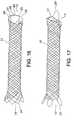
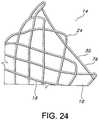
- FIGS. 23-25depict additional details of the stent end 14 having the retrieval and/or repositioning loop 28.
- the wire 32may have a substantially or partially extending circumferential portion 76 and a longitudinally extending portion 50 so that the sections 30 and 34 of the retrieval and/or repositioning loop 28 are juxtaposed or have portion that are juxtaposed with one and the other, desirably in slidably relationship which may also be an abutting relationship.
- the stent 10may be used for a number of purposes including to maintain patency of a body lumen, vessel or conduit, such as in the coronary or peripheral vasculature, esophagus, trachea, bronchi colon, biliary tract, urinary tract, prostate, brain, and the like.
- the devices of the present inventionmay also be used to support a weakened body lumen or to provide a fluid-tight conduit for a body lumen.
- the general tubular shapemay be varied.
- the tubular shapemay have a varied diameter, may be tapered, and may have an outwardly flared end and the like.
- the ends of the stentmay have a larger diameter than the middle regions of the stent.
- at least one of the ends of the stenttransition from one diameter to another diameter. Desirably, both ends transition in this manner to yield "flared" ends, as depicted in FIG. 19 .
- the stentmay be coated with a polymeric material.
- the stent wiresmay be partially or fully covered with a biologically active material which is elutably disposed with the polymeric material.
- the polymeric coatingmay extend over or through the interstitial spaces between the stent wires so as to provide a hollow tubular liner or cover over the interior or the exterior surface of the stent.
- the polymeric materialmay be selected from the group consisting of polyester, polypropylene, polyethylene, polyurethane, polynaphthalene, polytetrafluoroethylene, expanded polytetrafluoroethylene, silicone, and combinations thereof.
- stent types and stent constructionsmay be employed in the invention.
- various stents usefulinclude, without limitation, self-expanding stents and balloon expandable extents.
- the stentsmay be capable of radially contracting, as well and in this sense can best be described as radially distensible or deformable.
- Self-expanding stentsinclude those that have a spring-like action which causes the stent to radially expand, or stents which expand due to the memory properties of the stent material for a particular configuration at a certain temperature.
- Nitinolis one material which has the ability to perform well while both in spring-like mode, as well as in a memory mode based on temperature.
- stentscan be fastened into a continuous helical pattern, with or without a wave-like or zig-zag in the wire, to form a radially deformable stent.
- Individual rings or circular memberscan be linked together such as by struts, sutures, welding or interlacing or locking of the rings to form a tubular stent.
- Tubular stents useful in the present inventionalso include those formed by etching or cutting a pattern from a tube.
- stentsare often referred to as slotted stents.
- stentsmay be formed by etching a pattern into a material or mold and depositing stent material in the pattern, such as by chemical vapor deposition or the like. Examples of various stent configurations are shown in U.S. Patent Nos. 4,503,569 to Dotter ; 4,733,665 to Palmaz ; 4,856,561 to Hillstead ; 4,580,568 to Gianturco ; 4,732,152 to Wallsten , 4,886,062 to Wiktor , and 5,876,448 to Thompson .
Landscapes
- Health & Medical Sciences (AREA)
- Engineering & Computer Science (AREA)
- Biomedical Technology (AREA)
- Cardiology (AREA)
- Oral & Maxillofacial Surgery (AREA)
- Transplantation (AREA)
- Heart & Thoracic Surgery (AREA)
- Vascular Medicine (AREA)
- Life Sciences & Earth Sciences (AREA)
- Animal Behavior & Ethology (AREA)
- General Health & Medical Sciences (AREA)
- Public Health (AREA)
- Veterinary Medicine (AREA)
- Media Introduction/Drainage Providing Device (AREA)
- Prostheses (AREA)
Description
- The present invention relates to implantable stents having a stent retrieval member or loop for easy retrieval and/or repositioning of the implanted stent.
- An intraluminal prosthesis is a medical device used in the treatment of diseased bodily lumens. One type of intraluminal prosthesis used in the repair and/or treatment of diseases in various body vessels is a stent. A stent is a generally longitudinal tubular device formed of biocompatible material which is useful to open and support various lumens in the body. For example, stents may be used in the vascular system, urogenital tract, esophageal tract, tracheal/bronchial tubes and bile duct, as well as in a variety of other applications in the body. These devices are implanted within the vessel to open and/or reinforce collapsing or partially occluded sections of the lumen.
- Stents generally include an open flexible configuration. This configuration allows the stent to be inserted through curved vessels. Furthermore, this configuration allows the stent to be configured in a radially compressed state for intraluminal catheter implantation. Once properly positioned adjacent the damaged vessel, the stent is radially expanded so as to support and reinforce the vessel. Radial expansion of the stent may be accomplished by inflation of a balloon attached to the catheter or the stent may be of the self-expanding variety which will radially expand once deployed. Structures which have been used as intraluminal vascular grafts have included coiled stainless steel springs; helically wound coil springs manufactured from a heat-sensitive material; and expanding stainless steel stents formed of stainless steel wire in a zig-zag pattern.
- Various techniques or systems have been proposed for retrieving and/or repositioning an implanted stent. For example,
U.S. Patent No. 5,643,277 to Soehendra et al. describes the use of a tapered, threaded cable for removal of an implanted stent. The threaded portion of the cable is described as being twisted to engage an implanted biliary stent, such as a polyethylene stent, and then pulled to remove the sent from the patient. U.S. Patent No. 6,676,692 to Rabkin et al. describes a catheter system having stent-capturing hooks. The hooks are described as being useful for engaging the stent, thereby allowing repositioning and/or retrieval of the stent.U.S. Patent Application Publication No. 2002/0188344 A1 to Bolea et al. describes the use of hinged hooks attached to interior portions of an implantable stent. Use of a retrieval tool is described as engaging the hooks, and, upon twisting of the retrieval tool, the stent is contracted thereby allowing retrieval of the stent. In another embodiment, a wire lasso is described as being secured to an implantable stent with the wire lasso having a small loop internally disposed within the open lumen of the stent. The loop of the lasso is described as being engaged by a retrieval tool, and, upon twisting of the retrieval tool, the stent is contracted thereby allowing retrieval of the stent. Other embodiments include a lasso wire threaded through eyelets at a stent end. A retrieval tool is described as engaging the lasso wire, and, upon twisting or axially pulling the lasso wire, the stent is contracted thereby allowing retrieval of the stent.US 2004116996 (A1 ) discloses removable, essentially cylindrical implants which can be reduced in diameter and are wrapped once or several times at one or more levels by one or more elastic, thin wire-shaped structure(s) which include(s) a catch device at least on one end thereof.US 6641608 (B1 ) discloses a stent shaped as a three-dimensional body which is formed by interlaced threads arranged in multistart turns of a helical line. The threads are arranged in at least two groups of the helical turns featuring opposite senses of helix. The stent ends are established by sections where the turns of one helical line merge into those of the other helical line, said sections appearing as a single length of the thread.US2002143387 discloses a stent modified by an addition of a tightening drawstring with a loop or region for grasping.WO2004105647 discloses in one of its embodiments a braided stent provided with a plurality of loop segments connected to an associated pair of strand couplings.- Prior retrieval systems may appear easy to use, but often require certain user-sensitive techniques, such as twisting or turning in order to reposition or remove the stent. Moreover, in smaller stents, such as biliary stents, the spacing between conventional stent segments is generally smaller than the size of standard forceps or graspers, making it even difficult to grab a hook or lasso.
- The present invention provides a stent a defined in claim 1, for example a braided stent, having an integral repositioning and/or retrieval loop. The stent includes at least two elongate wires interlooped to form a tubular stent having opposed tirst and second open ends with each open end having a circumference, wherein the at least two wires are formed into a repositioning and/or retrieval loop which comprises a first section of one of the at least two wires that partially circumscribes said circumference of said first open end. The loop further comprises a second section of a second, different wire of said at least two wires; said second section having a circumferentially portion that partially traverses said circumference of said first end, wherein the circumferential portion of the second wire section is juxtaposingly disposed to a portion of the circumferential portion of the first wire section. Desirably, the at least interlooped two wires are braided. The first wire of the first section may cross over the second wire of the second section at the circumferential portion of the second wire loop. The first wire at the circumferential portion of the first wire loop may be attached to the second wire at the circumferential portion of the second wire loop.
- Desirably, the wires include biocompatible metallic and/or polymeric materials. Useful materials include nitinol, cobalt-based alloy, stainless steel, platinum, gold, titanium, tantalum, niobium, polymeric and combinations thereof. Desirably, the wires include nitinol. The wires may be composite wires for improved radiopacity. Such composite wires may have an inner core of tantalum, gold, platinum, iridium or combination of thereof and an outer portion of nitinol.
- In an aspect of the present invention, a braided stent having an integral repositioning and/or retrieval loop is provided. The braided stent includes a plurality of wires having first and second ends interbraided in a braided pattern to form a tubular stent having opposed atraumatic first and second open ends with each open end having a circumference; wherein the first and second wires ends are disposed at the second stent open end and the wires are looped at the second stent open end so that none of the first or second wires ends are exposed at the circumference of second stent open end; wherein at least of two of the wires are formed into a repositioning and/or retrieval loop having an elongated portion circumferentially disposed at the first opposed open end; and wherein the reposition and/or retrieval loop includes two sections which run adjacent to each other prior to crossing to permit grabbing of both sections simultaneously by a practitioner. The first section of the reposition and/or retrieval loop includes a first wire loop substantially traversing the first circumference formed from one of the stent wires; and the second section of the reposition and/or retrieval loop includes a second wire loop partially traversing the first circumference formed from another of the stent wires, wherein the circumferential portion of the second wire loop is juxtaposingly disposed to a portion of the circumferential portion of the first wire loop. Desirably, the second wire loop includes two legs longitudinally extending from the interbraided portion of the stent. The legs may include a base and an apex, wherein the base is integral with the interbraided portion of the stent and where the wire is angularly bent at the apices to form the circumferential portion of the second wire loop.
- Desirably, the first wire at the circumferential portion of the first wire loop crosses over the second wire at the circumferential portion of the second wire loop. The first wire at the circumferential portion of the first wire loop may also be attached to the second wire at the circumferential portion of the second wire loop.
- Except for the second wire, the wires at the first stent end may have an angular bend defining the initial portion of the braided pattern. The first wire at the circumferential portion of the first wire loop may cross over at least one of the angular bends at the first stent end or the first wire at the circumferential portion of the first wire loop may be attached to at least one of the angular bends at the first stent end.
- The wires may be made from biocompatible metallic and/or polymeric materials. Desirably, the wire materials are selected from the group consisting of nitinol, cobalt-based alloy, stainless steel, platinum, gold, titanium, tantalum, niobium, polymeric and combinations thereof. Desirably, the wires include nitinol. The wires may be composite wires for improved radiopacity. The composite wires may have an inner core of tantalum, gold, platinum, iridium or combination of thereof and an outer portion of nitinol.
- Desirably, the stent includes an even number of wires from about 10 to about 36.
- The stent may further include a hollow tubular covering disposed over the interior or the exterior surface. The tubular covering may be an uninterrupted covering. The tubular covering may substantially cover the stent. The tubular covering may partially cover portions of the stent. Desirably, the tubular covering substantially covers the stent, excluding portions of the repositioning and/or retrieval loop. Desirably, the covering is a polymeric material. Useful polymeric materials may include polyester, polypropylene, polyethylene, polyurethane, polynaphthalene, polytetrafluoroethylene, expanded polytetrafluoroethylene, silicone, and combinations thereof.
- A method for producing a tubular braided stent having opposed first and second stent ends and having an integral repositioning and/or retrieval loop at the first stent end is disclosed. The method includes the steps of selecting a plurality of elongate biocompatible wires having opposed ends; forming a reposition and/or retrieval loop from two of the wires including two sections which run adjacent to each other prior to crossing to permit grabbing of both sections simultaneously by a practitioner; and braiding the wires to form the stent. The step for forming the reposition and/or retrieval loop may further include forming a first section by circumferentially disposing one wire prior to braiding. The step for forming the reposition and/or retrieval loop may further include forming a second section by circumferentially disposing a second wire and angularly bending the second wire to form two longitudinally legs prior to braiding. The step of braiding the wires may further include braiding the wires such that the opposed wires ends terminate at the second end of the stent. The method may further include bending the wires at the second end to form wire loops thereat. The method may further include welding the wire ends to form closed wire loops thereat. Desirably, the wire ends are welded proximal to a portion of the closed wire loops. The wire ends may be welded at a braided wire portion located proximally, but before, the closed wire loop ends.
- Desirably, the step of selecting wires further includes selecting an even number of wires. The even number of wires may be from about 10 to about 36.
- Desirably, the wires at the first end of the stent are angularly bent prior to the step of braiding so that no wire ends are disposed at the first end of the stent. The wires at the first end of the stent may be angularly bent to form wire bends prior to the step of braiding so that no wire ends are disposed at the first end of the stent, and further wherein the one wire forming the first section crosses over at least one of the wire bends.
- A method of repositioning and/or retrieving an implantable stent is described. The method includes the steps of providing a stent, which includes a plurality of wires having first and second ends interbraided in a braided pattern to form a tubular stent having opposed atraumatic first and second open ends with each open end having a circumference; wherein the first and second wires ends are disposed at the second stent open end and the wires are looped at the second stent open end so that none of the first or second wires ends are exposed at the circumference of second stent open end; wherein at least of two of the wires are formed into a repositioning and/or retrieval loop having an elongated portion circumferentially disposed at the first opposed open end; and wherein the reposition and/or retrieval loop includes two sections which run adjacent to each other prior to crossing; and grabbing of both sections the reposition and/or retrieval loop simultaneously to reposition and/or retrieve the stent. Desirably, the step of grabbing further includes using forceps to both sections the reposition and/or retrieval loop. The use of an implantable stent having a repositioning and/or retrieving loop is provided. Desirably, in use the stent includes a plurality of wires having first and second ends interbraided in a braided pattern to form a tubular stent having opposed atraumatic first and second open ends with each open end having a circumference; wherein the first and second wires ends are disposed at the second stent open end and the wires are looped at the second stent open end so that none of the first or second wires ends are exposed at the circumference of second stent open end; wherein at least of two of the wires are formed into a repositioning and/or retrieval loop having an elongated portion circumferentially disposed at the first opposed open end; and wherein the reposition and/or retrieval loop includes two sections which run adjacent to each other prior to crossing; wherein both sections the reposition and/or retrieval loop may be simultaneously accessed or grabbed to reposition and/or retrieve the stent. Desirably, the accessing or grabbing of the both sections further includes use of forceps to both sections the reposition and/or retrieval loop.
FIG. 1 is a perspective view of a hollow, tubular stent according to the present invention.FIG. 2 is an expanded view of a wall portion of the stent ofFIG. 1 taken along the 2-2 axis showing a plurality of stent wires.FIG. 3 depicts a braided stent with a closed-end loop design having atraumatic stent ends with no loose wires ends thereat.FIG. 4 is a perspective view on one end of the stent ofFIG. 3 having a retrieval and/or repositioning loop according to the present invention.FIG. 5 is a front perspective view of the retrieval and/or repositioning loop ofFIG. 4 according to the present invention.FIG. 6 is a side perspective view of the retrieval and/or repositioning loop ofFIG. 4 according to the present invention.FIG. 7 is a back perspective view of the retrieval and/or repositioning loop ofFIG. 4 according to the present invention.FIG. 8 is an expanded view of the retrieval and/or repositioning loop ofFIG. 5 according to the present invention.FIG. 9 is an expanded view of the retrieval and/or repositioning loop ofFIG. 7 according to the present invention.FIG. 10 is an expanded view of the retrieval and/or repositioning loop ofFIG. 6 according to the present invention.FIG. 11A is another view of the retrieval and/or repositioning loop ofFIG. 4 according to the present invention.FIG. 11B is a view of the stent ofFIG. 11 in a retracted or compressed state according to the present invention.FIG. 12 is a perspective view of a mandrel useful for forming the retrieval and/or repositioning loop ofFIG. 4 according to the present invention.FIG. 13 is a flat schematic of the mandrel ofFIG. 12 showing pin and wire details.FIG. 14 is an expanded view of a grabbing or access area of the retrieval and/or repositioning loop ofFIG. 4 according to the present invention.FIG. 15 is a top schematic view of a circumferential wire forming the retrieval and/or repositioning loop ofFIG. 4 according to the present invention.FIG. 16 is a depiction of a stent having an embodiment of the retrieval and/or repositioning loop according to the present invention.FIG. 17 is a depiction of a stent having another embodiment of the retrieval and/or repositioning loop according to the present invention and further having a polymeric coating.FIG. 18 is a schematic depiction for a technique for providing the polymeric coating on the stent according to the present invention.FIG. 19A is a schematic depiction for offset welding of stent wire ends according to the present invention.FIG. 19B is a view of the stent ofFIG. 19A having the offset welds according to the present invention.FIG. 20 depicts a stent having a covering of silicone according to the present invention.FIG. 21 is a cross-section view of the stent ofFIG. 20 showing an outer covering of silicone about the stent according to the present invention.FIG. 22 is a cross-section view of the stent ofFIG. 20 showing an inner covering of silicone about the stent according to the present invention.FIG. 23 is another expanded view of the retrieval and/or repositioning loop ofFIG. 4 according to the present invention.FIG. 24 is another expanded view of the retrieval and/or repositioning loop ofFIG. 4 according to the present invention.FIG. 25 is another expanded view of the retrieval and/or repositioning loop ofFIG. 4 according to the present invention.- The present invention provides at least one retrieval and/or repositioning loop (RRL) which is integral and formed from at least two of the wires which are braided to form the stent. The retrieval and/or repositioning loop retrieval and/or repositioning loop is designed to provide a structure which has the required tensile strength to prevent fracture or damage to the stent when force is applied to reposition or retrieve the stent, yet allows for a very low delivery profile such that it can easily be loaded onto a delivery device without interfering with the deployment into the body or requiring increased deployment force. Since the retrieval and/or repositioning loop retrieval and/or repositioning loop is part of the actual braided stent structureper se, as opposed to being a separate add-on element, no joining, i.e., welding, crimping or twisting, of the retrieval and/or repositioning loop retrieval and/or repositioning loop to the braided stent structure is necessary. Tensile strength of the retrieval and/or repositioning loop may thus be maximized while concomitantly maintaining the lowest profile for delivery to a patient. The wire or wires used to form at least one retrieval and/or repositioning loop may be of the same type and material as the other wires forming the braided stent, or alternatively they may be made from different types or materials. In one desirable embodiment, the retrieval and/or repositioning loop is made from wire which is the same material and diameter, i.e., outside diameter (OD), as other wires which form the braided stent. In this manner, the retrieval and/or repositioning loop can further seamlessly transition into the body of the stent. As used herein, the phrase "retrieval and/or repositioning loop" refers to a retrieval loop, a repositioning loop, or a combination thereof which is integrally formed with a stent and, when a longitudinally pulling force is applied thereto, aids in the radial contraction or cinching of the stent to facilitate movement, repositioning and/or retrieval of the stent.
- More than one retrieval and/or repositioning loop may be incorporated into the stent. For example, each stent end might have one or more retrieval and/or repositioning loops. In some embodiments only one retrieval and/or repositioning loop is present at one or more ends.
FIG. 1 depictsstent 10 of the present invention.Stent 10 is a hollow tubular structure having opposed first and second open ends12,14 and having atubular wall 16 therebetween. A portion of thetubular wall 16 is depicted inFIG. 2 as having a plurality ofelongate wires 18 formed into thetubular wall 16. Theelongate wires 18 traverse the length of thestent 10 in a direction traverse to the longitudinal length of thestent 10. Theelongate wires 18 may be formed into thetubular wall 16 by braiding thewires 18, winding thewires 18, knitting thewires 18, and combinations thereof. Preferably, thewires 18 are braided in abraided pattern 20 to form thetubular wall 16. A useful nonlimiting braided pattern includes a one over and one under pattern, but other patterns may suitably be used.- As depicted in
FIG. 3 ,stent 10 is desirably an atraumatic stent having no sharp terminating members at one or both of the opposed first and second open ends12,14. Theelongate wires 18 terminating atopen end 12 are mated to formclosed loops 22 and adjacently mated wires are secured to one and the other by mechanical means, such as welds26. The positioning of adjacently mated wires to form closed-loop end designs is further described in U.S. Published application No.US 2005-0049682 A1 , andU.S. Provisional Application No. 60/680,630 U.S. Patent Application No. 11/271,774 on November 10, 2005 - Desirably, the
elongate wires 18 terminating atopen end 12 are in a cathedral type arch or loop configuration. Further details of the cathedral type of arch or closed-loop configuration may be found inU.S. Application No. 10/845,844, filed May 15, 2004 - The
stent wires 18 at theopen end 14 are bent to form closed loop ends24 thereat. As depicted inFIG. 3 , the loop ends24 are substantially angular having approximately or about a 90° bend. The radius of curvature at the point of the bend is desirably minimized. In other words, the loop ends24 desirably have an angularly bent portion between substantially straight wire portions that do not otherwise have a portion with a significant radius of curvature. The loop ends24, however, are not limited to angular bends of 90° and other bend angles may suitably be used. For example, angular bends with a bend angle from about 30° to about 150° are also useful. Other useful bend angles include from about 60° to about 120°, from about 70° to about 110°, from about 80° to about 100°, from about 85° to about 95°, and the like. - The
stent 10 depicted inFIG. 3 includes multiple wires, such as 24wires 18 as depicted inFIG. 3 , of nitinol or nitinol-containing material. The wires are relatively thin at a diameter of about 0,28 mm (0, 011 inches). The number of wires and the diameters of the wires, which may be the same or different, depicted inFIG. 3 are not limiting, and other numbers of wires and other wire diameters may suitably be used. Desirably, an even number of wires are used, for example from about 10 to about 36 wires. - Desirably, the
wires 18 are made from any suitable implantable material, including without limitation nitinol, stainless steel, cobalt-based alloy such as Elgiloy®, platinum, gold, titanium, tantalum, niobium, polymeric materials and combinations thereof. Useful and nonlimiting examples of polymeric stent materials include poly(L-lactide) (PLLA), poly(D,L-lactide) (PLA), poly(glycolide) (PGA), poly(L-lactide-co-D,L-lactide) (PLLA/PLA), poly(L-lactide-co-glycolide) (PLLA/PGA), poly(D,L-lactide-co-glycolide) (PLA/PGA), poly(glycolide-co-trimethylene carbonate) (PGA/PTMC), polydioxanone (PDS), Polycaprolactone (PCL), polyhydroxybutyrate (PHBT), poly(phosphazene) poly(D,L-lactide-co-caprolactone) PLA/PCL), poly(glycolide-co-caprolactone) (PGA/PCL), poly(phosphate ester) and the like. Wires made from polymeric materials may be also include radiopaque materials, such as metallic-based powders, particulates or pastes which may be incorporated into the polymeric material. For example the radiopaque material may be blended with the polymer composition from which the polymeric wire is formed, and subsequently fashioned into the stent as described herein. Alternatively, the radiopaque material may be applied to the surface of the metal or polymer stent. In either embodiment, various radiopaque materials and their salts and derivatives may be used including, without limitation, bismuth, barium and its salts such as barium sulphate, tantulaum, tungsten, gold, platinum and titanium, to name a few. Additional useful radiopaque materials may be found inU.S. Patent No. 6,626,936 . - Metallic complexes useful as radiopaque materials are also contemplated. The stent may be selectively made radiopaque at desired areas along the wire or made be fully radiopaque, depending on the desired end-product and application. Further, the
wires 18 have an inner core of tantalum, gold, platinum, iridium or combination of thereof and an outer member or layer of nitinol to provide a composite wire for improved radiocapicity or visibility. Desirably, the inner core is platinum and the outer layer is nitinol. More desirably, the inner core of platinum represents about at least 10% of the wire based on the overall cross-sectional percentage. Moreover, nitinol that has not been treated for shape memory such as by heating, shaping and cooling the nitinol at its martensitic and austenitic phases, is also useful as the outer layer. Further details of such composite wires may be found inU.S. Patent Application Publication 2002/0035396 A1 . - Preferably, the
wires 18 are made from nitinol, or a composite wire having a central core of platinum and an outer layer of nitinol. Further, the filling weld material, if required by welding processes such as MIG, may also be made from nitinol, stainless steel, cobalt-based alloy such as Elgiloy, platinum, gold, titanium, tantalum, niobium, and combinations thereof, preferably nitinol. The material of the cathode is no critical and can be made out of any suitable metal. The filling weld material and thewire 18 may be made of the same material, for example nitinol. - Further, the
wires 18 may have a composite construction, such as described found inU.S. Patent Application Publication 2002/0035396 A1 . - For example, the
wires 18 may have an inner core of tantalum gold, platinum, iridium or combination of thereof and an outer member or layer of nitinol to provide a composite wire for improved radiocapicity or visibility. Preferably, thewires 18 are made from nitinol. - Either of both of the opposed open ends12,14 of the
stent 10 has/have a retrieval and/or repositioning loop thereat. The retrieval and/or repositioning loop is useful for repositioning and/or retrieval of an implanted or deployedstent 10. The retrieval and/or repositioning loop allows a practitioner to contract and move, reposition and/or retrieve thestent 10 within an implanted lumen (not shown). The stent retrieval member may be made from a memory shape alloy, such as the above described materials, including nitinol. The use of a shape memory material, as compared other convention materials such as suture thread, has numerous advantages. For example, the self-supporting nature of the shape memory material facilitates the locating of the retrieval and/or repositioning loop. A memory shape alloy member will not tangle, a potential problem with suture loops, especially with suture loops made from natural or polymeric threads or filaments, and will also aid in opening thestent 10. Another advantage from using a memory shape alloy material is the wire loop defining the retrieval and/or repositioning loop would be less likely to break than a plastic or polymeric loop when a pulling force is applied, such as required for repositioning or removal of thestent 10. - As depicted in
FIG. 4 thestent 10 includes the retrieval and/orrepositioning loop 28. The retrieval and/orrepositioning loop 28 includes afirst section 30 having astent wire 32 that is substantially circumferentially disposed theend 14 ofstent 10. The retrieval and/orrepositioning loop 28 includes asecond section 34 having a circumferential portion that only partially traverses the circumference of theend 14 ofstent 10. The retrieval and/or repositioning loopsecond section 34 includes twolegs braid 20 of thestent 10. In other words, thebase 40 of thelegs braided pattern 20 of thestent 10. Thewire 32 forming thefirst section 30 of the retrieval and/orrepositioning loop 28 is also desirably part of thebraid pattern 20 of thestent 10. In other words, thewire 32, after forming thefirst section 30 of the retrieval and/orrepositioning loop 28, enters into thenormal braiding pattern 20 of thestent 10. The apex42 of thelegs top portion 44 having a length that partially circumvents the circumference of thestent end 14. Thetop portion 44 is provided with a circumferential length to permit easy access by a practitioner of the retrieval and/orrepositioning loop 28. When thefirst section 30 and thesecond section 34 of the retrieval and/orrepositioning loop 28 are accessed and pulled, such as byportion 46 of the retrieval and/orrepositioning loop 28 where infirst section 30 and thesecond section 34 are juxtaposingly disposed to one and another, thestent end 14 is axially compressed or radially contracted by a cinching action of the circumferential portion of thewire 32. Such aportion 34 may also be referred to as a grabbing area orportion 34 as it is configured for easy access by a practitioner, for example a practitioner using forceps (not shown). Further, as wires forming both the first andsection sections braid pattern 20 of thestent 10, such integral wires further facilitate movement, repositioning or retrieval of thestent 10 by, among other things, providing a cinching or radially contracting action along the longitudinal length of the stent and also by transferring the pulling force along the longitudinal length of the stent. Thus, the pulling of the retrieval and/orrepositioning loop 28 provides for simultaneous contracting and pulling of thestent 10. In contrast, if a pulling force is applied to an end of a stent without having a retrieval and/orrepositioning loop 28, there is no cinching or radial contracting force generated at that stent end. For example, assuming there is not retrieval and/orrepositioning loop 28 integrally formed and disposed at thestent end 12, when a practitioner pulls on theclosed loops 22 ofstent end 12 to generate a pulling force thereat, a cinching or radial contracting force is not generated at thatend 12 of thestent 10. In a similar manner, assuming there is not retrieval and/orrepositioning loop 28 integrally formed and disposed at thestent end 14, when a practitioner pulls on the loop ends24 ofstent end 14 to generate a pulling force thereat, a cinching or radial contracting force is not generated at thatend 14 of thestent 10. FIG. 5 depicts a partial front view of thestent 10 having the retrieval and/orrepositioning loop 28 of the present invention. Thestent wires 18 on the front face of thestent 10 are depicted, but thestent wires 18 on the back face are not shown for simplicity and for better illustration of the retrieval and/orrepositioning loop 28 of the present invention. The.FIG. 6 depicts a side view of thestent 10 having the retrieval and/orrepositioning loop 28.FIG. 7 depicts a back view of thestent 10 having the retrieval and/orrepositioning loop 28. As depicted inFIGS. 5-7 the retrieval and/orrepositioning loop 28 desirably extends longitudinally outward from the braided portions forming the remaining portion of thestent end 14. Such extended and elongated retrieval and/or repositioning loop100 facilitates grabbing of the retrieval and/or repositioning loop100 by a practitioner.- As depicted in
FIG. 8 , thewire 32 forming the first section102 of the retrieval and/or repositioning loop100 may cross over the wire the wire forming the second section104. This advantageously permits a practitioner to grab bothsection 30 of the retrieval and/orrepositioning loop 28 advantageously circumscribes the circumferential perimeter of theend 14 of thestent 10. Such a encompassing of the circumferential perimeter of thestent end 14 facilitates access by a practitioner and also facilitates in a cinching action of thestent end 14 when a longitudinal pulling force is applied to the retrieval and/orrepositioning loop 28 of the present invention. The present invention, however, is not limited to a wire, forexample wire 32, or afirst section 30 which completely circumscribes the circumferential perimeter of thestent end 14. For example,wire 32 or thefirst section 30 may suitably substantially circumscribe the circumferential perimeter of thestent end 14 or may suitably partially circumscribe the circumferential perimeter of thestent end 14. FIG. 6 depicts a partial side view of thestent 10 having the retrieval and/orrepositioning loop 28 of the present invention. Thestent wires 18 on the front side face of thestent 10 are depicted, but thestent wires 18 on the back side face are not shown for simplicity and for better illustration of the retrieval and/orrepositioning loop 28 of the present invention. As depicted inFIG. 6 , thewire 30 extends longitudinally away or outward from thestent end 14 so that it is juxtaposingly disposed with thesecond section 34 at the grabbingarea 46. Such a longitudinal extent facilitates access to the retrieval and/orrepositioning loop 28 of the present invention by, for example, a practitioner.FIG. 7 depicts a partial back view of thestent 10 having the retrieval and/orrepositioning loop 28. Thestent wires 18 on the back face of thestent 10 are depicted, but thestent wires 18 on the front face are not shown for simplicity and for better illustration of the retrieval and/orrepositioning loop 28 of the present invention. Thestent wires 18 on the front side face of thestent 10 are depicted, but thestent wires 18 on the back side face are not shown for simplicity and for better illustration. Thesecond section 34 of the retrieval and/orrepositioning loop 28 has a shape of an inverted "U", i.e., the top oflegs top portion 44 of thesecond section 34, while the bottom of thelegs area 46 or thetop portion 44 is pulled thelegs stent end 14 and ofstent 10 of present invention. As depicted inFIGS. 5-7 the retrieval and/orrepositioning loop 28 desirably extends longitudinally outward from the braided portions forming the remaining portion of thestent end 14. Such an extended and elongated retrieval and/orrepositioning loop 28 facilitates grabbing of the retrieval and/orrepositioning loop 28 by a practitioner.FIG. 8 is an expanded partial view of the wires forming the retrieval and/orrepositioning loop 28 of the present invention. Thewire 32 offirst section 30 of the retrieval and/orrepositioning loop 28 of the present invention may juxtaposingly cross over thewire 48 of thesecond portion 34 at thetop portion 44 ofsecond section 34. Thewires wires sections stent 10. The present invention, however, is not so limited and thewires - As depicted in
FIGS. 9-10 , thewire 32 forming thefirst section 30 of the retrieval and/orrepositioning loop 28 may cross through some, but not all, of the angular bends24 atstent end 14. For example, some of the angular bends24 may be longitudinally offset from other of the angular bends24, and thewire 32 may suitably cross through thosebends 24 at the very end of thestent 10 while no crossing through thebends 24 that are disposed inwardly from thestent end 14. As depicted inFIG. 9 , the angular bends24 are longitudinally offset from one and the other, but the present invention is not so limited. For example, thestent 10 may have no offsetting of thebends 24 atstent end 14. Further, as depicted inFIG. 10 , as indicated bywire portion 76, thewire 32 forming thefirst section 30 of the retrieval and/orrepositioning loop 28 may extend substantially about the circumference of thestent end 14, which is defined by the angular bends24, and then have alongitudinal extent 50 jutting away from thestent end 14. Thetop portion 52 of the longitudinal extend50 may then cross thetop portion 44 of the second section34 (not shown) of the retrieval and/orrepositioning loop 28. This aspect of the retrieval and/orrepositioning loop 28 of the present invention differs from the aspect depicted inFIG. 6 where thewire 32 traverses from one or moreangular bends 24 in a diagonal fashion toward the grabbingarea 46 of the retrieval and/orrepositioning loop 28. The present invention, however, is not so limited, and thewire 32, i.e. thetop portion 52, need not cross the grabbingarea 46 of thesecond section 34. In such an aspect or the present invention, the retrieval and/orrepositioning loop 28 may be formed by thewire 32 and does not have to include thewire 48. In other words, the retrieval and/orrepositioning loop 28 of the present invention may suitably be formed from only thefirst section 30 where thewire 32 extends substantially about the circumference of thestent end 14. In such an aspect of the present invention, thefirst section 30, when pulled, provides a cinching or radial contraction action and a longitudinal stretching action for movement, repositioning or retrieval of thestent 10. Further, as depicted inFIG. 10 , thetop portion 52 of the retrieval and/orrepositioning loop 28 may extend radially outward from thestent end 14 to facilitate access by a practitioner. The present invention, however, is not so limited, and thetop portion 52 of the retrieval and/orrepositioning loop 28 may extend slightly inwardly in a radially fashion or be substantially longitudinally in line or parallel with the longitudinal wall of thestent 10. Such a radially inward, radially outwardly or radially parallel configuration may also be present in the grabbingarea 46 having both the first andsecond sections repositioning loop 28 of the present invention. - As depicted in
FIGS. 11-12 , thestent 10 easily contracts upon application of a pulling force, "P", to the retrieval and/orrepositioning loop 28. - Referring to
FIGS. 12-13 , the retrieval and/orrepositioning loop 28 of the present invention may be formed by wrapping one wire, forexample wire 32, around template pins56 disposed on amandrel 54 prior to braiding thestent 10 to form a perimetrical section58 which is generally circular. Such a perimetrical section58 desirably forms thefist section 30 of the retrieval and/orrepositioning loop 28 of the present invention. The retrieval and/orrepositioning loop 28 also then may be provided with a largerexaggerated section 60, such as grabbingarea 46, for easy grabbing by the practitioner or physician. Thisexaggerated section repositioning loop 28 is also formed by wrapping asecond wire 48 around template pins56 positioned on themandrel 54 to cause the desired looped shape. A pulling force on the retrieval and/orrepositioning loop 28 will cause cinching of the braid to a smaller diameter as it lengthens axial, by thus allowing for less frictional force against the vessel wall and permitting repositioning and/or retrieval of the deployed stent. The retrieval and/or repositioning loop wires are then braided in with the other wires, forexample wires 18, using the braiding technique as described herein. - The retrieval and/or repositioning loop may be interlaced with one or more adjacent end loops formed from other wires as it is wrapped around the mandrel, or it need not be interlaced with any adjacent wire loops at the stent end. In the latter case, optional attachment methods such as sutures or clamps may be used to attach the retrieval and/or repositioning loop to one or more adjacent end loops of the stent. Having the retrieval and/or repositioning loop interlace with one or more, and desirably at least two adjacent end loops from the other adjacent wires is one particularly desirable embodiment.
- In one particularly useful embodiment, the retrieval and/or repositioning loop is designed to be grabbed at the area where the
stent wires repositioning loop 28 crosses themselves as shown inFIG. 8 . The retrieval and/orrepositioning loop 28 may have an exaggerated loop ordistended section FIG. 14 , the grabbingarea 46 where the retrieval and/orrepositioning loop wires area 46 is desirably sized for at least two of the wire crossings in the braid pattern of the stent. - The grabbing area of the retrieval and/or repositioning loop can be positioned at any desired location along the wire from which it is formed prior to the wire crossing adjacent wires to begin the braid. In such cases the retrieval and/or repositioning loop may be a single pull wire and the pull length may be longer (approximately twice the length) than the pull length of those designed to be pulled at the section where the retrieval and/or repositioning loop crosses itself.
- The retrieval and/or repositioning loop may also have the same or different properties than other wires which form the braided stent. For example, it may be of the same or different stiffness or flexibility, all of which may be tailored for a particular application. The choice of material, wire diameter and pre-treatment of the wires and stent configuration are some of the factors which may be varied to achieve particular stent properties. Additionally, as mentioned herein, the at least one retrieval and/or repositioning loop may also be made radiopaque by various methods, for example with a coating or finish, with a band or as part of the stent material, as further described herein. Color or different finishes may also be added to the retrieval and/or repositioning loop to visually differentiate it from the rest of the stent wires.
- As depicted in
FIG. 14 , the grabbingarea 46 includes two juxtaposed wires32,148. The grabbingarea 46, however, is not so limited. As depicted inFIG. 15 , the retrieval and/or repositioning loop28' may include only thecircumferential wire 32 that is subsequently interbraided to form thestent 10. Further as depicted inFIG. 15 , thecircumferential wire 32, whether forming the retrieval and/or repositioning loop28' by itself or forming the retrieval and/orrepositioning loop 28 in conjunction with anotherstent wire 48, is desirably part of the braidedwires 18 used in forming thestent 10, thereby forming the integral retrieval and/orrepositioning loop 28 of the present invention. Thestent 10 may then be braided to form a tubular structure.Stent wires 18 are disposed aboutpins 62 and after which braiding of the wires commence. Additional details of braiding may be found inU.S. Patent No. 6,792,979 , - As depicted in
FIGS. 16-17 , thestent 10 of the present invention may have the integral retrieval and/orrepositioning loop 28,28' integrally formed at eitherstent - Further the
stent 10 of the present invention may have a coating. Desirably, the coating is a tubular covering of silicone. As depicted inFIG. 18 , thestent 10 may be placed on a coating mandrel (not shown) by means of atie 64 after which the assembly is dipped into a silicone solution to form the coating. Desirably, the retrieval and/orrepositioning loop portion 28 is not silicone covered. Desirably the coating or covering is a silicone covering, but other coverings, particularly elastomeric polymers, are useful. The coating embeds thestent 10 therein and essentially forms a stent covering. When coating, it is desirable not to embed the retrieval and/orrepositioning loop section 28, 28' in the covering, although the other wire portions emanating from the retrieval and/orrepositioning loop 28, 28' which form the braid of the stent may be coated. To prevent coating of the retrieval and/or repositioning loop section, the mandrel may be truncated or geometrically altered such that it does not permit coating of the retrieval and/or repositioning loop, or the retrieval and/or repositioning loop can be pulled away from the mandrel during coating and formation of the polymer covering. - In one embodiment of the present invention, one end of the
stent 10 may haveweld joints 68 which, due to their positioning, provide higher radial strength, i.e., theresultant stents 10 can withstand higher radial compressive forces without fear of weld failure. In these embodiments, the weld joint68 is positioned between the crossings of adjacent wires, as shown inFIGS. 19A and 19B . As depicted inFIG. 19A ,wires 18 to be welded may be disposed about islands or pins66 on a mandrel (not shown). After thewelds 68 are formed or while thewelds 68 are being formed wire portions not forming thestent 10 may be cut or otherwise removed from thestent braiding pattern 20. - As depicted in
FIG. 20 , thestent 10 may be fully, substantially or partially covered or lined with apolymeric material 70. Thestent 10 may also be embedded in a polymeric coating. The covering may be in the form of a tubular structure. Nonlimiting examples of useful polymeric materials include polyesters, polypropylenes, polyethylenes, polyurethanes, polynaphthalenes, polytetrafluoroethylenes, expanded polytetrafluoroethylene, silicone, and combinations and copolymers thereof. Desirably, thepolymeric material 70 is silicone. The polymeric material and/orsilicone 70 may be disposed onexternal surfaces 72 of thestent 10, as depicted inFIG. 21 , or disposed on theinternal surfaces 74 of thestent 10, as depicted inFIG. 22 , or combinations thereof. FIGS. 23-25 depict additional details of thestent end 14 having the retrieval and/orrepositioning loop 28. As depicted inFIGS. 23-25 , which are partial schematic views showing generally onlyfront face wires 18 in thebraid pattern 20, thewire 32 may have a substantially or partially extendingcircumferential portion 76 and alongitudinally extending portion 50 so that thesections repositioning loop 28 are juxtaposed or have portion that are juxtaposed with one and the other, desirably in slidably relationship which may also be an abutting relationship.- With any embodiment, the
stent 10 may be used for a number of purposes including to maintain patency of a body lumen, vessel or conduit, such as in the coronary or peripheral vasculature, esophagus, trachea, bronchi colon, biliary tract, urinary tract, prostate, brain, and the like. The devices of the present invention may also be used to support a weakened body lumen or to provide a fluid-tight conduit for a body lumen. - Also, the stent10 may be treated with any known or useful bioactive agent or drug including without limitation the following: anti-thrombogenic agents (such as heparin, heparin derivatives, urokinase, and PPack (dextrophenylalanine proline arginine chloromethylketone); anti-proliferative agents (such as enoxaprin, angiopeptin, or monoclonal antibodies capable of blocking smooth muscle cell proliferation, hirudin, and acetylsalicylic acid); anti-inflammatory agents (such as dexamethasone, prednisolone, corticosterone, budesonide, estrogen, sulfasalazine, and mesalamine); antineoplastic/antiproliferative/anti-miotic agents (such as paclitaxel, 5-fluorouracil, cisplatin, vinblastine, vincristine, epothilones, endostatin, angiostatin and thymidine kinase inhibitors); anesthetic agents (such as lidocaine, bupivacaine, and ropivacaine); anti-coagulants (such as D-Phe-Pro-Arg chloromethyl keton, an RGD peptide-containing compound, heparin, antithrombin compounds, platelet receptor antagonists, anti-thrombin antibodies, anti-platelet receptor antibodies, aspirin, prostaglandin inhibitors, platelet inhibitors and tick antiplatelet peptides); vascular cell growth promotors (such as growth factor inhibitors, growth factor receptor antagonists, transcriptional activators, and translational promotors); vascular cell growth inhibitors (such as growth factor inhibitors, growth factor receptor antagonists, transcriptional repressors, translational repressors, replication inhibitors, inhibitory antibodies, antibodies directed against growth factors, bifunctional molecules consisting of a growth factor and a cytotoxin, bifunctional molecules consisting of an antibody and a cytotoxin); cholesterol-lowering agents; vasodilating agents; and agents which interfere with endogenous vascoactive mechanisms.
- Further, with any embodiment of the
stent 10 the general tubular shape may be varied. For example, the tubular shape may have a varied diameter, may be tapered, and may have an outwardly flared end and the like. Further, the ends of the stent may have a larger diameter than the middle regions of the stent. In one particularly useful embodiment, at least one of the ends of the stent transition from one diameter to another diameter. Desirably, both ends transition in this manner to yield "flared" ends, as depicted inFIG. 19 . - The stent may be coated with a polymeric material. For example, the stent wires may be partially or fully covered with a biologically active material which is elutably disposed with the polymeric material. Further, the polymeric coating may extend over or through the interstitial spaces between the stent wires so as to provide a hollow tubular liner or cover over the interior or the exterior surface of the stent. The polymeric material may be selected from the group consisting of polyester, polypropylene, polyethylene, polyurethane, polynaphthalene, polytetrafluoroethylene, expanded polytetrafluoroethylene, silicone, and combinations thereof.
- Various stent types and stent constructions may be employed in the invention. Among the various stents useful include, without limitation, self-expanding stents and balloon expandable extents. The stents may be capable of radially contracting, as well and in this sense can best be described as radially distensible or deformable. Self-expanding stents include those that have a spring-like action which causes the stent to radially expand, or stents which expand due to the memory properties of the stent material for a particular configuration at a certain temperature. Nitinol is one material which has the ability to perform well while both in spring-like mode, as well as in a memory mode based on temperature. Other materials are of course contemplated, such as stainless steel, platinum, gold, titanium and other biocompatible metals, as well as polymeric stents. The configuration of the stent may also be chosen from a host of geometries. For example, wire stents can be fastened into a continuous helical pattern, with or without a wave-like or zig-zag in the wire, to form a radially deformable stent. Individual rings or circular members can be linked together such as by struts, sutures, welding or interlacing or locking of the rings to form a tubular stent. Tubular stents useful in the present invention also include those formed by etching or cutting a pattern from a tube. Such stents are often referred to as slotted stents. Furthermore, stents may be formed by etching a pattern into a material or mold and depositing stent material in the pattern, such as by chemical vapor deposition or the like. Examples of various stent configurations are shown in
U.S. Patent Nos. 4,503,569 to Dotter ;4,733,665 to Palmaz ;4,856,561 to Hillstead ;4,580,568 to Gianturco ;4,732,152 to Wallsten ,4,886,062 to Wiktor , and5,876,448 to Thompson . - The invention being thus described, it will now be evident to those skilled in the art that the same may be varied in many ways. Such variations are not to be regarded as a departure from the scope of the invention and all such modifications are intended to be included within the scope of the following claims. Further, any of the embodiments or aspects of the invention as described in the claims may be used with one and another without limitation.
Claims (9)
- A stent (10) comprising:at least two elongate wires (32, 48) interlooped to form a tubular stent having opposed first and second open ends (12, 14) with each open end having a circumference, wherein said at least two wires (32, 48) are formed into a repositioning and/or retrieval loop (28, 28') disposed at said first open end (12),wherein said repositioning and/or retrieval loop (28, 28') comprisesa first section (30) of a first wire (32) of said at least two wires that at least partially circumscribes said circumference of said first end; anda second section (34) of a second, different wire (48) of said at least two wires, said second section (34) having a circumferential portion (44) that partially traverses said circumference of said first end;wherein the circumferential portion (44) of said second section (34) is juxtaposingly disposed to a portion of said first section (30).
- The stent of claim 1, wherein said at least interlooped two wires are braided.
- The stent of claim 1, wherein said first wire (32) at said portion of said first section (30) crosses over said second wire (48) at said circumferential portion of said second section (34).
- The stent of claim 1, wherein said first wire (32) at said portion of said first section (30) is attached to said second wire (48) at said circumferential portion of said second section (34).
- The stent of claim 1, wherein the wires comprise biocompatible metallic and/or polymeric materials.
- The stent of claim 5, wherein said metallic materials are selected from the group consisting of nitinol, cobalt-based alloy, stainless steel, platinum, gold, titanium, tantalum, niobium, polymeric and combinations thereof.
- The stent of claim 6, wherein said wires comprise nitinol.
- The stent of claim 5, wherein said wires are composite wires for improved radiopacity.
- The stent of claim 8, wherein said wires have an inner core of tantalum, gold, platinum, iridium or combination of thereof and an outer portion of nitinol.
Priority Applications (2)
| Application Number | Priority Date | Filing Date | Title |
|---|---|---|---|
| EP19185559.2AEP3597256B1 (en) | 2005-05-13 | 2006-05-11 | Integrated stent repositioning and retrieval loop |
| EP13180768.7AEP2666508B1 (en) | 2005-05-13 | 2006-05-11 | Integrated stent repositioning and retrieval loop |
Applications Claiming Priority (2)
| Application Number | Priority Date | Filing Date | Title |
|---|---|---|---|
| US68068905P | 2005-05-13 | 2005-05-13 | |
| PCT/US2006/018337WO2006124541A2 (en) | 2005-05-13 | 2006-05-11 | Integrated stent repositioning and retrieval loop |
Related Child Applications (3)
| Application Number | Title | Priority Date | Filing Date |
|---|---|---|---|
| EP13180768.7ADivision-IntoEP2666508B1 (en) | 2005-05-13 | 2006-05-11 | Integrated stent repositioning and retrieval loop |
| EP13180768.7ADivisionEP2666508B1 (en) | 2005-05-13 | 2006-05-11 | Integrated stent repositioning and retrieval loop |
| EP19185559.2ADivisionEP3597256B1 (en) | 2005-05-13 | 2006-05-11 | Integrated stent repositioning and retrieval loop |
Publications (2)
| Publication Number | Publication Date |
|---|---|
| EP1887974A2 EP1887974A2 (en) | 2008-02-20 |
| EP1887974B1true EP1887974B1 (en) | 2018-04-25 |
Family
ID=37000029
Family Applications (3)
| Application Number | Title | Priority Date | Filing Date |
|---|---|---|---|
| EP06759623.9AActiveEP1887974B1 (en) | 2005-05-13 | 2006-05-11 | Integrated stent repositioning and retrieval loop |
| EP19185559.2AActiveEP3597256B1 (en) | 2005-05-13 | 2006-05-11 | Integrated stent repositioning and retrieval loop |
| EP13180768.7AActiveEP2666508B1 (en) | 2005-05-13 | 2006-05-11 | Integrated stent repositioning and retrieval loop |
Family Applications After (2)
| Application Number | Title | Priority Date | Filing Date |
|---|---|---|---|
| EP19185559.2AActiveEP3597256B1 (en) | 2005-05-13 | 2006-05-11 | Integrated stent repositioning and retrieval loop |
| EP13180768.7AActiveEP2666508B1 (en) | 2005-05-13 | 2006-05-11 | Integrated stent repositioning and retrieval loop |
Country Status (5)
| Country | Link |
|---|---|
| US (6) | US9265634B2 (en) |
| EP (3) | EP1887974B1 (en) |
| JP (1) | JP5008660B2 (en) |
| ES (1) | ES2671416T3 (en) |
| WO (1) | WO2006124541A2 (en) |
Families Citing this family (128)
| Publication number | Priority date | Publication date | Assignee | Title |
|---|---|---|---|---|
| US7018401B1 (en) | 1999-02-01 | 2006-03-28 | Board Of Regents, The University Of Texas System | Woven intravascular devices and methods for making the same and apparatus for delivery of the same |
| US20080300314A1 (en)* | 2003-11-21 | 2008-12-04 | Givaudan Sa | Cooling Compounds |
| US20060206200A1 (en)* | 2004-05-25 | 2006-09-14 | Chestnut Medical Technologies, Inc. | Flexible vascular occluding device |
| US7462192B2 (en)* | 2004-11-10 | 2008-12-09 | Boston Scientific Scimed, Inc. | Atraumatic stent with reduced deployment force, method for making the same and method and apparatus for deploying and positioning the stent |
| DE102005003632A1 (en) | 2005-01-20 | 2006-08-17 | Fraunhofer-Gesellschaft zur Förderung der angewandten Forschung e.V. | Catheter for the transvascular implantation of heart valve prostheses |
| US9301862B2 (en)* | 2005-01-28 | 2016-04-05 | Boston Scientific Scimed, Inc. | Stent retrieval member and devices and methods for retrieving or repositioning a stent |
| EP1887974B1 (en) | 2005-05-13 | 2018-04-25 | Boston Scientific Limited | Integrated stent repositioning and retrieval loop |
| EP1988851A2 (en)* | 2006-02-14 | 2008-11-12 | Sadra Medical, Inc. | Systems and methods for delivering a medical implant |
| US8535368B2 (en) | 2006-05-19 | 2013-09-17 | Boston Scientific Scimed, Inc. | Apparatus for loading and delivering a stent |
| WO2008047369A2 (en)* | 2006-10-18 | 2008-04-24 | Inspiremd Ltd. | Knitted stent jackets |
| MX2009004291A (en) | 2006-10-22 | 2009-09-07 | Idev Technologies Inc | Methods for securing strand ends and the resulting devices. |
| US7896915B2 (en) | 2007-04-13 | 2011-03-01 | Jenavalve Technology, Inc. | Medical device for treating a heart valve insufficiency |
| US8187284B2 (en) | 2007-04-23 | 2012-05-29 | Boston Scientific Scimed, Inc. | Intraluminary stent relocating apparatus |
| US9034007B2 (en) | 2007-09-21 | 2015-05-19 | Insera Therapeutics, Inc. | Distal embolic protection devices with a variable thickness microguidewire and methods for their use |
| US9393137B2 (en) | 2007-09-24 | 2016-07-19 | Boston Scientific Scimed, Inc. | Method for loading a stent into a delivery system |
| CZ303081B6 (en)* | 2007-12-13 | 2012-03-21 | Ella-Cs, S. R. O. | Process for producing self-expansion biologically degradable stent |
| US8623071B2 (en)* | 2008-01-07 | 2014-01-07 | DePuy Synthes Products, LLC | Radiopaque super-elastic intravascular stent |
| US9044318B2 (en) | 2008-02-26 | 2015-06-02 | Jenavalve Technology Gmbh | Stent for the positioning and anchoring of a valvular prosthesis |
| BR112012021347A2 (en) | 2008-02-26 | 2019-09-24 | Jenavalve Tecnology Inc | stent for positioning and anchoring a valve prosthesis at an implantation site in a patient's heart |
| AT506842B1 (en)* | 2008-06-12 | 2010-03-15 | Michaela Dr Abrahamowicz | DEVICE FOR DIAGNOSIS OF AN INNER RECTANGULAR PROLAPSE AND SURFACE SOIL REDUCTION AND FOR DETERMINING DOUGLAS DEPTH |
| DE102008002641A1 (en)* | 2008-06-25 | 2009-12-31 | Biotronik Vi Patent Ag | Fiber strand and implantable support body with a fiber strand |
| DE102008033170A1 (en) | 2008-07-15 | 2010-01-21 | Acandis Gmbh & Co. Kg | A braided mesh implant and method of making such an implant |
| DE102008036429A1 (en) | 2008-08-05 | 2010-02-11 | Acandis Gmbh & Co. Kg | Medical implant |
| WO2010091383A2 (en) | 2009-02-09 | 2010-08-12 | St. Jude Medical | Inflatable minimally invasive system for delivering and securing an annular implant |
| GB0903247D0 (en)* | 2009-02-26 | 2009-04-08 | Depuy Int Ltd | Support structure implant for a bone cavity |
| KR20100119068A (en)* | 2009-04-30 | 2010-11-09 | (주) 태웅메디칼 | Stent removal can strain the structure of the hooks |
| CA2767035C (en)* | 2009-07-02 | 2015-07-21 | The Cleveland Clinic Foundation | Apparatus and method for replacing a diseased cardiac valve |
| WO2011031587A1 (en)* | 2009-09-10 | 2011-03-17 | Boston Scientific Scimed, Inc. | Endoprosthesis with filament repositioning or retrieval member and guard structure |
| EP3081196B1 (en)* | 2009-09-21 | 2018-04-18 | Boston Scientific Scimed, Inc. | Integrated stent retrieval loop adapted for snare removal and/or optimized purse stringing |
| EP2485689B1 (en) | 2009-10-09 | 2020-03-18 | Boston Scientific Scimed, Inc. | Stomach bypass |
| KR101109708B1 (en)* | 2009-10-27 | 2012-01-31 | (주) 태웅메디칼 | Prostate urethral dilatation stent |
| CA2788111C (en)* | 2010-01-29 | 2016-04-05 | Cook Medical Technologies Llc | Collapsing structure for reducing the diameter of a stent |
| US8632582B2 (en) | 2010-03-25 | 2014-01-21 | Mayo Foundation For Medical Education And Research | Removable and/or retrievable stents and kits |
| WO2011137043A1 (en)* | 2010-04-30 | 2011-11-03 | Boston Scientific Scimed, Inc. | Apparatus and method for manufacturing a single wire stent |
| KR101160646B1 (en)* | 2010-05-14 | 2012-06-29 | 신경민 | Abstinence-only stent on the prevention of food emissions |
| US10856978B2 (en) | 2010-05-20 | 2020-12-08 | Jenavalve Technology, Inc. | Catheter system |
| JP5801037B2 (en)* | 2010-05-25 | 2015-10-28 | アクセスポイント テクノロジーズ有限会社 | Stent |
| WO2011147849A1 (en) | 2010-05-25 | 2011-12-01 | Jenavalve Technology Inc. | Prosthetic heart valve and transcatheter delivered endoprosthesis comprising a prosthetic heart valve and a stent |
| EP2582331B1 (en)* | 2010-06-18 | 2017-09-13 | Synthes GmbH | Spine disc replacement with compliant articulating core |
| DE102010027123A1 (en)* | 2010-07-14 | 2012-01-19 | Acandis Gmbh & Co. Kg | Medical device |
| JP6055163B2 (en)* | 2010-07-27 | 2016-12-27 | アクセスポイント テクノロジーズ有限会社 | Stent |
| DE102010044746A1 (en)* | 2010-09-08 | 2012-03-08 | Phenox Gmbh | Implant for influencing the blood flow in arteriovenous malformations |
| US8945207B2 (en) | 2010-12-20 | 2015-02-03 | Graftcraft I Göteborg Ab | Removable stent and method of production |
| CN103379882B (en) | 2010-12-20 | 2015-12-16 | 哥德堡移植技术公司 | Removable stent and method of production |
| JP2013019347A (en)* | 2011-07-12 | 2013-01-31 | Nihon Glassfiber Industrial Co Ltd | Metal wire compressed body |
| US9839541B2 (en) | 2011-08-22 | 2017-12-12 | Cook Medical Technologies Llc | Reconstrainable stent system |
| JP6346861B2 (en)* | 2012-04-06 | 2018-06-20 | ボストン サイエンティフィック サイムド,インコーポレイテッドBoston Scientific Scimed,Inc. | Endoprosthesis and method for manufacturing the same |
| US8882828B2 (en)* | 2012-04-27 | 2014-11-11 | Medtronic Vascular, Inc. | Ring on a closed web stent-graft for use in tip capture |
| JP6139664B2 (en) | 2012-09-12 | 2017-05-31 | ボストン サイエンティフィック サイムド,インコーポレイテッドBoston Scientific Scimed,Inc. | Stent and method for producing stent |
| JP6139665B2 (en) | 2012-10-25 | 2017-05-31 | ボストン サイエンティフィック サイムド,インコーポレイテッドBoston Scientific Scimed,Inc. | Stent |
| US10327778B2 (en)* | 2013-02-28 | 2019-06-25 | Boston Scientific Scimed, Inc. | Stent with balloon for repair of anastomosis surgery leaks |
| US20140257362A1 (en)* | 2013-03-07 | 2014-09-11 | St. Jude Medical, Cardiology Division, Inc. | Filtering and removing particulates from bloodstream |
| US9265635B2 (en) | 2013-03-14 | 2016-02-23 | Boston Scientific Scimed, Inc. | Stent having removable anchoring element |
| CN105228688B (en) | 2013-03-15 | 2019-02-19 | 伊瑟拉医疗公司 | Vascular treatment devices and methods |
| US8679150B1 (en) | 2013-03-15 | 2014-03-25 | Insera Therapeutics, Inc. | Shape-set textile structure based mechanical thrombectomy methods |
| WO2014150130A1 (en)* | 2013-03-15 | 2014-09-25 | Merit Medical Systems, Inc. | Esophageal stent |
| US8715314B1 (en) | 2013-03-15 | 2014-05-06 | Insera Therapeutics, Inc. | Vascular treatment measurement methods |
| US8690907B1 (en) | 2013-03-15 | 2014-04-08 | Insera Therapeutics, Inc. | Vascular treatment methods |
| JP6396466B2 (en) | 2013-08-08 | 2018-09-26 | ボストン サイエンティフィック サイムド,インコーポレイテッドBoston Scientific Scimed,Inc. | Stents comprising a soluble or degradable adhesive polymer to prevent stent migration |
| CN105491978A (en) | 2013-08-30 | 2016-04-13 | 耶拿阀门科技股份有限公司 | Radially collapsible frame for a prosthetic valve and method for manufacturing such a frame |
| WO2015142536A1 (en) | 2014-03-17 | 2015-09-24 | Boston Scientific Scimed, Inc. | Platelet-activated bioadhesive stent coating as an antimigration mechanism |
| AU2015277089B2 (en)* | 2014-06-18 | 2017-11-02 | Boston Scientific Scimed, Inc. | Biliary stent |
| JP6423541B2 (en) | 2015-01-16 | 2018-11-14 | ボストン サイエンティフィック サイムド,インコーポレイテッドBoston Scientific Scimed,Inc. | Implantable medical device with movement restraint |
| EP3250157B1 (en)* | 2015-01-28 | 2024-08-28 | Aortic Innovations, LLC | Modular endo-aortic device |
| KR101696810B1 (en)* | 2015-02-04 | 2017-02-01 | 주식회사 엠아이텍 | Stent for connecting adjacent tissues and manufacturing method thereof |
| EP3270825B1 (en) | 2015-03-20 | 2020-04-22 | JenaValve Technology, Inc. | Heart valve prosthesis delivery system |
| KR101728319B1 (en)* | 2015-04-15 | 2017-04-19 | 주식회사 엠아이텍 | Methods for Manufacturing Stent |
| US10709555B2 (en) | 2015-05-01 | 2020-07-14 | Jenavalve Technology, Inc. | Device and method with reduced pacemaker rate in heart valve replacement |
| BR102015011376B1 (en) | 2015-05-18 | 2023-04-04 | Murilo Pundek Rocha | IMPLANTABLE ARTIFICIAL BRONCHI |
| JP6581292B2 (en)* | 2015-08-17 | 2019-09-25 | ボストン サイエンティフィック サイムド,インコーポレイテッドBoston Scientific Scimed,Inc. | Radioactive stent |
| USD784267S1 (en)* | 2015-08-17 | 2017-04-18 | Tessco Communications Incorporated | Cable braiding and strain relief |
| EP3349669B1 (en)* | 2015-09-18 | 2020-10-21 | Terumo Corporation | Vessel prosthesis |
| US10004617B2 (en) | 2015-10-20 | 2018-06-26 | Cook Medical Technologies Llc | Woven stent device and manufacturing method |
| CN108697423A (en) | 2016-02-16 | 2018-10-23 | 伊瑟拉医疗公司 | The part flow arrangement of suction unit and anchoring |
| US10426592B2 (en) | 2016-04-11 | 2019-10-01 | Boston Scientific Scimed, Inc. | Implantable medical device with reduced migration capabilities |
| US10390944B2 (en)* | 2016-04-13 | 2019-08-27 | Hlt, Inc. | Braided support structure |
| WO2017195125A1 (en) | 2016-05-13 | 2017-11-16 | Jenavalve Technology, Inc. | Heart valve prosthesis delivery system and method for delivery of heart valve prosthesis with introducer sheath and loading system |
| US10568754B2 (en) | 2016-05-13 | 2020-02-25 | Boston Scientific Scimed, Inc. | Protective apparatus for use in gastrointestinal tract |
| US10470904B2 (en) | 2016-05-18 | 2019-11-12 | Boston Scientific Scimed, Inc. | Stent retrieval system |
| CN109688988A (en)* | 2016-09-19 | 2019-04-26 | 波士顿科学医学有限公司 | Systems, devices and methods for treating endometriosis |
| DE102016013721A1 (en)* | 2016-11-17 | 2018-05-17 | Grammer Ag | Spring, use of a plastic tube as a spring and equipment part of a vehicle interior |
| WO2018138658A1 (en) | 2017-01-27 | 2018-08-02 | Jenavalve Technology, Inc. | Heart valve mimicry |
| EP4238539A3 (en)* | 2017-10-25 | 2023-10-18 | Boston Scientific Scimed, Inc. | Stent with atraumatic spacer |
| IL275123B2 (en)* | 2017-12-06 | 2024-06-01 | Butterfly Medical Ltd | Urological implant having extraction handle and/or arched members |
| EP4364703A3 (en) | 2018-02-20 | 2024-07-31 | Boston Scientific Scimed, Inc. | Drainage device |
| US12076226B2 (en) | 2018-03-19 | 2024-09-03 | Butterfly Medical Ltd. | Urological implant having extraction handle and/or arched members |
| ES2725273B2 (en)* | 2018-03-20 | 2020-01-23 | Univ Zaragoza | REMOVABLE INTRALUMINAL PROTESIS, SUITABLE FOR THE TREATMENT OF Tracheomalacia |
| US11738075B2 (en)* | 2018-03-20 | 2023-08-29 | National Research Council Of Canada | Method for lyophilizing live vaccine strains of Francisella tularensis |
| WO2019195860A2 (en) | 2018-04-04 | 2019-10-10 | Vdyne, Llc | Devices and methods for anchoring transcatheter heart valve |
| DE102018207575A1 (en) | 2018-05-16 | 2019-11-21 | Kardion Gmbh | Magnetic face turning coupling for the transmission of torques |
| DE102018208550A1 (en) | 2018-05-30 | 2019-12-05 | Kardion Gmbh | A lead device for directing blood flow to a cardiac assist system, cardiac assist system, and method of making a lead device |
| DE102018208538A1 (en) | 2018-05-30 | 2019-12-05 | Kardion Gmbh | Intravascular blood pump and process for the production of electrical conductors |
| DE102018208541A1 (en) | 2018-05-30 | 2019-12-05 | Kardion Gmbh | Axial pump for a cardiac assist system and method of making an axial pump for a cardiac assist system |
| DE102018208539A1 (en) | 2018-05-30 | 2019-12-05 | Kardion Gmbh | A motor housing module for sealing an engine compartment of a motor of a cardiac assist system and cardiac assistance system and method for mounting a cardiac assist system |
| CN119424058A (en)* | 2018-06-04 | 2025-02-14 | 波士顿科学国际有限公司 | Removable bracket |
| DE102018210076A1 (en) | 2018-06-21 | 2019-12-24 | Kardion Gmbh | Method and device for detecting a state of wear of a cardiac support system, method and device for operating a cardiac support system and cardiac support system |
| DE102018210058A1 (en) | 2018-06-21 | 2019-12-24 | Kardion Gmbh | Stator blade device for guiding the flow of a fluid flowing out of an outlet opening of a heart support system, heart support system with stator blade device, method for operating a stator blade device and manufacturing method |
| CN112654389A (en) | 2018-08-07 | 2021-04-13 | 开迪恩有限公司 | Bearing device for a cardiac support system and method for flushing an intermediate space in a bearing device for a cardiac support system |
| WO2020049734A1 (en)* | 2018-09-07 | 2020-03-12 | オリンパス株式会社 | Stent |
| US10321995B1 (en) | 2018-09-20 | 2019-06-18 | Vdyne, Llc | Orthogonally delivered transcatheter heart valve replacement |
| US11071627B2 (en) | 2018-10-18 | 2021-07-27 | Vdyne, Inc. | Orthogonally delivered transcatheter heart valve frame for valve in valve prosthesis |
| US11344413B2 (en) | 2018-09-20 | 2022-05-31 | Vdyne, Inc. | Transcatheter deliverable prosthetic heart valves and methods of delivery |
| US12310850B2 (en) | 2018-09-20 | 2025-05-27 | Vdyne, Inc. | Transcatheter deliverable prosthetic heart valves and methods of delivery |
| US12186187B2 (en) | 2018-09-20 | 2025-01-07 | Vdyne, Inc. | Transcatheter deliverable prosthetic heart valves and methods of delivery |
| US11278437B2 (en) | 2018-12-08 | 2022-03-22 | Vdyne, Inc. | Compression capable annular frames for side delivery of transcatheter heart valve replacement |
| CN113164271B (en) | 2018-09-24 | 2025-01-21 | 波士顿科学国际有限公司 | Repositionable and removable bracket |
| US11109969B2 (en)* | 2018-10-22 | 2021-09-07 | Vdyne, Inc. | Guidewire delivery of transcatheter heart valve |
| CN113329716A (en)* | 2018-11-16 | 2021-08-31 | 微仙美国有限公司 | Radiopaque vascular prosthesis |
| EP4252712B1 (en)* | 2018-11-19 | 2025-03-26 | Pulmair Medical, Inc. | Implantable artificial bronchus |
| JP7494444B2 (en)* | 2018-12-14 | 2024-06-04 | 住友ベークライト株式会社 | Anchor Stent |
| US11253359B2 (en) | 2018-12-20 | 2022-02-22 | Vdyne, Inc. | Proximal tab for side-delivered transcatheter heart valves and methods of delivery |
| WO2020146842A1 (en) | 2019-01-10 | 2020-07-16 | Vdyne, Llc | Anchor hook for side-delivery transcatheter heart valve prosthesis |
| US11185409B2 (en) | 2019-01-26 | 2021-11-30 | Vdyne, Inc. | Collapsible inner flow control component for side-delivered transcatheter heart valve prosthesis |
| US11273032B2 (en) | 2019-01-26 | 2022-03-15 | Vdyne, Inc. | Collapsible inner flow control component for side-deliverable transcatheter heart valve prosthesis |
| WO2020181154A2 (en) | 2019-03-05 | 2020-09-10 | Vdyne, Inc. | Tricuspid regurgitation control devices for orthogonal transcatheter heart valve prosthesis |
| US11076956B2 (en) | 2019-03-14 | 2021-08-03 | Vdyne, Inc. | Proximal, distal, and anterior anchoring tabs for side-delivered transcatheter mitral valve prosthesis |
| US11173027B2 (en) | 2019-03-14 | 2021-11-16 | Vdyne, Inc. | Side-deliverable transcatheter prosthetic valves and methods for delivering and anchoring the same |
| WO2020222364A1 (en)* | 2019-04-29 | 2020-11-05 | 주식회사 에스앤지바이오텍 | Removable stent including loop and pulling member for removing stent |
| CA3138875A1 (en) | 2019-05-04 | 2020-11-12 | Vdyne, Inc. | Cinch device and method for deployment of a side-delivered prosthetic heart valve in a native annulus |
| CA3142835C (en) | 2019-06-17 | 2024-01-30 | Boston Scientific Scimed, Inc. | Covered endoprosthesis with improved branch access |
| EP4480458A3 (en) | 2019-08-20 | 2025-04-09 | Vdyne, Inc. | Delivery devices for side-deliverable transcatheter prosthetic valves |
| CN120531525A (en) | 2019-08-26 | 2025-08-26 | 维迪内股份有限公司 | Laterally deliverable transcatheter prosthetic valve and method for its delivery and anchoring |
| USD902407S1 (en)* | 2019-11-19 | 2020-11-17 | Pulmair Medical, Inc. | Implantable artificial bronchus |
| US11234813B2 (en) | 2020-01-17 | 2022-02-01 | Vdyne, Inc. | Ventricular stability elements for side-deliverable prosthetic heart valves and methods of delivery |
| USD954953S1 (en) | 2020-11-03 | 2022-06-14 | Pulmair Medical, Inc. | Implantable artificial bronchus |
| CN112618105B (en)* | 2020-12-31 | 2024-04-12 | 上海翰凌医疗器械有限公司 | Valve support, and matching device with valve support and conveying mechanism |
| WO2024102411A1 (en) | 2022-11-09 | 2024-05-16 | Jenavalve Technology, Inc. | Catheter system for sequential deployment of an expandable implant |
| USD1014758S1 (en) | 2023-04-19 | 2024-02-13 | Pulmair Medical, Inc. | Implantable artificial bronchus |
Family Cites Families (30)
| Publication number | Priority date | Publication date | Assignee | Title |
|---|---|---|---|---|
| US4503569A (en) | 1983-03-03 | 1985-03-12 | Dotter Charles T | Transluminally placed expandable graft prosthesis |
| US4580568A (en) | 1984-10-01 | 1986-04-08 | Cook, Incorporated | Percutaneous endovascular stent and method for insertion thereof |
| ES8705239A1 (en) | 1984-12-05 | 1987-05-01 | Medinvent Sa | A device for implantation and a method of implantation in a vessel using such device. |
| US4733665C2 (en) | 1985-11-07 | 2002-01-29 | Expandable Grafts Partnership | Expandable intraluminal graft and method and apparatus for implanting an expandable intraluminal graft |
| US4886062A (en) | 1987-10-19 | 1989-12-12 | Medtronic, Inc. | Intravascular radially expandable stent and method of implant |
| US4856561A (en) | 1987-11-10 | 1989-08-15 | Hydro Conduit Corporation | Seal construction for bell and spigot pipe |
| US4856516A (en) | 1989-01-09 | 1989-08-15 | Cordis Corporation | Endovascular stent apparatus and method |
| EP0466412B1 (en) | 1990-07-09 | 1995-03-29 | Wilson-Cook Medical Inc. | Device for retrieving stents |
| US7101392B2 (en) | 1992-03-31 | 2006-09-05 | Boston Scientific Corporation | Tubular medical endoprostheses |
| EP0633798B1 (en)* | 1992-03-31 | 2003-05-07 | Boston Scientific Corporation | Vascular filter |
| EP0639958A1 (en) | 1992-05-08 | 1995-03-01 | Schneider (Usa) Inc. | Esophageal stent and delivery tool |
| US6336938B1 (en)* | 1992-08-06 | 2002-01-08 | William Cook Europe A/S | Implantable self expanding prosthetic device |
| RU2089131C1 (en) | 1993-12-28 | 1997-09-10 | Сергей Апполонович Пульнев | Stent-expander |
| US6340367B1 (en)* | 1997-08-01 | 2002-01-22 | Boston Scientific Scimed, Inc. | Radiopaque markers and methods of using the same |
| US6174330B1 (en) | 1997-08-01 | 2001-01-16 | Schneider (Usa) Inc | Bioabsorbable marker having radiopaque constituents |
| US6264689B1 (en)* | 1998-03-31 | 2001-07-24 | Scimed Life Systems, Incorporated | Low profile medical stent |
| US6656218B1 (en)* | 1998-07-24 | 2003-12-02 | Micrus Corporation | Intravascular flow modifier and reinforcement device |
| US7018401B1 (en) | 1999-02-01 | 2006-03-28 | Board Of Regents, The University Of Texas System | Woven intravascular devices and methods for making the same and apparatus for delivery of the same |
| US6398803B1 (en)* | 1999-02-02 | 2002-06-04 | Impra, Inc., A Subsidiary Of C.R. Bard, Inc. | Partial encapsulation of stents |
| US20020143387A1 (en)* | 2001-03-27 | 2002-10-03 | Soetikno Roy M. | Stent repositioning and removal |
| DE10118944B4 (en) | 2001-04-18 | 2013-01-31 | Merit Medical Systems, Inc. | Removable, essentially cylindrical implants |
| US6676692B2 (en) | 2001-04-27 | 2004-01-13 | Intek Technology L.L.C. | Apparatus for delivering, repositioning and/or retrieving self-expanding stents |
| US6821291B2 (en) | 2001-06-01 | 2004-11-23 | Ams Research Corporation | Retrievable stent and method of use thereof |
| US7001425B2 (en)* | 2002-11-15 | 2006-02-21 | Scimed Life Systems, Inc. | Braided stent method for its manufacture |
| US20040225349A1 (en)* | 2003-05-09 | 2004-11-11 | Thistle Robert C. | Eversible locking mechanism for modular stents |
| DE602004032127D1 (en) | 2003-05-23 | 2011-05-19 | Boston Scient Ltd | STENTS WITH RUNNING BELTS |
| US7993387B2 (en) | 2004-05-14 | 2011-08-09 | Boston Scientific Scimed, Inc. | Stent with reduced weld profiles and a closed-end wire configuration |
| US8337543B2 (en)* | 2004-11-05 | 2012-12-25 | Boston Scientific Scimed, Inc. | Prosthesis anchoring and deploying device |
| US7462192B2 (en) | 2004-11-10 | 2008-12-09 | Boston Scientific Scimed, Inc. | Atraumatic stent with reduced deployment force, method for making the same and method and apparatus for deploying and positioning the stent |
| EP1887974B1 (en)* | 2005-05-13 | 2018-04-25 | Boston Scientific Limited | Integrated stent repositioning and retrieval loop |
- 2006
- 2006-05-11EPEP06759623.9Apatent/EP1887974B1/enactiveActive
- 2006-05-11EPEP19185559.2Apatent/EP3597256B1/enactiveActive
- 2006-05-11EPEP13180768.7Apatent/EP2666508B1/enactiveActive
- 2006-05-11USUS11/432,065patent/US9265634B2/enactiveActive
- 2006-05-11ESES06759623.9Tpatent/ES2671416T3/enactiveActive
- 2006-05-11WOPCT/US2006/018337patent/WO2006124541A2/enactiveApplication Filing
- 2006-05-11JPJP2008511381Apatent/JP5008660B2/ennot_activeExpired - Fee Related
- 2016
- 2016-01-18USUS14/997,984patent/US10111766B2/enactiveActive
- 2016-02-26USUS15/055,527patent/US10149776B2/enactiveActive
- 2018
- 2018-10-03USUS16/150,885patent/US11013624B2/enactiveActive
- 2021
- 2021-05-03USUS17/306,082patent/US11786386B2/enactiveActive
- 2023
- 2023-09-06USUS18/462,185patent/US20230404782A1/enactivePending
Non-Patent Citations (1)
| Title |
|---|
| None* |
Also Published As
| Publication number | Publication date |
|---|---|
| EP3597256A1 (en) | 2020-01-22 |
| ES2671416T3 (en) | 2018-06-06 |
| US20190029851A1 (en) | 2019-01-31 |
| US20210251784A1 (en) | 2021-08-19 |
| US11013624B2 (en) | 2021-05-25 |
| US20160175125A1 (en) | 2016-06-23 |
| WO2006124541A2 (en) | 2006-11-23 |
| US20230404782A1 (en) | 2023-12-21 |
| US9265634B2 (en) | 2016-02-23 |
| WO2006124541A3 (en) | 2009-03-05 |
| EP3597256B1 (en) | 2023-01-18 |
| EP1887974A2 (en) | 2008-02-20 |
| EP2666508B1 (en) | 2019-07-24 |
| US10111766B2 (en) | 2018-10-30 |
| US11786386B2 (en) | 2023-10-17 |
| US20160128853A1 (en) | 2016-05-12 |
| JP2008545453A (en) | 2008-12-18 |
| US20060276887A1 (en) | 2006-12-07 |
| JP5008660B2 (en) | 2012-08-22 |
| EP2666508A1 (en) | 2013-11-27 |
| US10149776B2 (en) | 2018-12-11 |
Similar Documents
| Publication | Publication Date | Title |
|---|---|---|
| US11786386B2 (en) | Integrated stent repositioning and retrieval loop | |
| US11583421B2 (en) | Stent retrieval system | |
| US10265203B2 (en) | Stent retrieval member and devices and methods for retrieving or repositioning a stent | |
| EP2407127B1 (en) | Atraumatic stent with reduced deployment force | |
| US8025693B2 (en) | Stent-graft having flexible geometries and methods of producing the same | |
| US20080009934A1 (en) | Endoprosthesis delivery system with stent holder | |
| KR102614314B1 (en) | Stent with atraumatic spacer |
Legal Events
| Date | Code | Title | Description |
|---|---|---|---|
| PUAI | Public reference made under article 153(3) epc to a published international application that has entered the european phase | Free format text:ORIGINAL CODE: 0009012 | |
| 17P | Request for examination filed | Effective date:20071207 | |
| AK | Designated contracting states | Kind code of ref document:A2 Designated state(s):AT BE BG CH CY CZ DE DK EE ES FI FR GB GR HU IE IS IT LI LT LU LV MC NL PL PT RO SE SI SK TR | |
| AX | Request for extension of the european patent | Extension state:AL BA HR MK YU | |
| DAX | Request for extension of the european patent (deleted) | ||
| R17D | Deferred search report published (corrected) | Effective date:20090305 | |
| 17Q | First examination report despatched | Effective date:20110808 | |
| RAP1 | Party data changed (applicant data changed or rights of an application transferred) | Owner name:BOSTON SCIENTIFIC LIMITED | |
| RAP1 | Party data changed (applicant data changed or rights of an application transferred) | Owner name:BOSTON SCIENTIFIC LIMITED | |
| RIC1 | Information provided on ipc code assigned before grant | Ipc:A61F 2/844 20130101ALI20170926BHEP Ipc:A61F 2/95 20130101ALI20170926BHEP Ipc:A61F 2/90 20130101ALI20170926BHEP Ipc:A61F 2/07 20130101ALI20170926BHEP Ipc:A61F 2/06 20130101AFI20170926BHEP | |
| GRAP | Despatch of communication of intention to grant a patent | Free format text:ORIGINAL CODE: EPIDOSNIGR1 | |
| STAA | Information on the status of an ep patent application or granted ep patent | Free format text:STATUS: GRANT OF PATENT IS INTENDED | |
| INTG | Intention to grant announced | Effective date:20171110 | |
| GRAS | Grant fee paid | Free format text:ORIGINAL CODE: EPIDOSNIGR3 | |
| GRAA | (expected) grant | Free format text:ORIGINAL CODE: 0009210 | |
| STAA | Information on the status of an ep patent application or granted ep patent | Free format text:STATUS: THE PATENT HAS BEEN GRANTED | |
| AK | Designated contracting states | Kind code of ref document:B1 Designated state(s):AT BE BG CH CY CZ DE DK EE ES FI FR GB GR HU IE IS IT LI LT LU LV MC NL PL PT RO SE SI SK TR | |
| REG | Reference to a national code | Ref country code:GB Ref legal event code:FG4D | |
| REG | Reference to a national code | Ref country code:CH Ref legal event code:EP | |
| REG | Reference to a national code | Ref country code:FR Ref legal event code:PLFP Year of fee payment:13 | |
| REG | Reference to a national code | Ref country code:AT Ref legal event code:REF Ref document number:992055 Country of ref document:AT Kind code of ref document:T Effective date:20180515 | |
| REG | Reference to a national code | Ref country code:IE Ref legal event code:FG4D | |
| REG | Reference to a national code | Ref country code:DE Ref legal event code:R096 Ref document number:602006055244 Country of ref document:DE | |
| REG | Reference to a national code | Ref country code:ES Ref legal event code:FG2A Ref document number:2671416 Country of ref document:ES Kind code of ref document:T3 Effective date:20180606 | |
| REG | Reference to a national code | Ref country code:NL Ref legal event code:FP | |
| PGFP | Annual fee paid to national office [announced via postgrant information from national office to epo] | Ref country code:ES Payment date:20180601 Year of fee payment:13 | |
| PGFP | Annual fee paid to national office [announced via postgrant information from national office to epo] | Ref country code:NL Payment date:20180514 Year of fee payment:13 Ref country code:FR Payment date:20180514 Year of fee payment:13 | |
| REG | Reference to a national code | Ref country code:LT Ref legal event code:MG4D | |
| PG25 | Lapsed in a contracting state [announced via postgrant information from national office to epo] | Ref country code:PL Free format text:LAPSE BECAUSE OF FAILURE TO SUBMIT A TRANSLATION OF THE DESCRIPTION OR TO PAY THE FEE WITHIN THE PRESCRIBED TIME-LIMIT Effective date:20180425 Ref country code:SE Free format text:LAPSE BECAUSE OF FAILURE TO SUBMIT A TRANSLATION OF THE DESCRIPTION OR TO PAY THE FEE WITHIN THE PRESCRIBED TIME-LIMIT Effective date:20180425 Ref country code:BG Free format text:LAPSE BECAUSE OF FAILURE TO SUBMIT A TRANSLATION OF THE DESCRIPTION OR TO PAY THE FEE WITHIN THE PRESCRIBED TIME-LIMIT Effective date:20180725 Ref country code:FI Free format text:LAPSE BECAUSE OF FAILURE TO SUBMIT A TRANSLATION OF THE DESCRIPTION OR TO PAY THE FEE WITHIN THE PRESCRIBED TIME-LIMIT Effective date:20180425 Ref country code:LT Free format text:LAPSE BECAUSE OF FAILURE TO SUBMIT A TRANSLATION OF THE DESCRIPTION OR TO PAY THE FEE WITHIN THE PRESCRIBED TIME-LIMIT Effective date:20180425 | |
| PG25 | Lapsed in a contracting state [announced via postgrant information from national office to epo] | Ref country code:GR Free format text:LAPSE BECAUSE OF FAILURE TO SUBMIT A TRANSLATION OF THE DESCRIPTION OR TO PAY THE FEE WITHIN THE PRESCRIBED TIME-LIMIT Effective date:20180726 Ref country code:LV Free format text:LAPSE BECAUSE OF FAILURE TO SUBMIT A TRANSLATION OF THE DESCRIPTION OR TO PAY THE FEE WITHIN THE PRESCRIBED TIME-LIMIT Effective date:20180425 | |
| REG | Reference to a national code | Ref country code:CH Ref legal event code:PL | |
| REG | Reference to a national code | Ref country code:AT Ref legal event code:MK05 Ref document number:992055 Country of ref document:AT Kind code of ref document:T Effective date:20180425 | |
| PG25 | Lapsed in a contracting state [announced via postgrant information from national office to epo] | Ref country code:PT Free format text:LAPSE BECAUSE OF FAILURE TO SUBMIT A TRANSLATION OF THE DESCRIPTION OR TO PAY THE FEE WITHIN THE PRESCRIBED TIME-LIMIT Effective date:20180827 | |
| REG | Reference to a national code | Ref country code:DE Ref legal event code:R097 Ref document number:602006055244 Country of ref document:DE | |
| REG | Reference to a national code | Ref country code:BE Ref legal event code:MM Effective date:20180531 | |
| PG25 | Lapsed in a contracting state [announced via postgrant information from national office to epo] | Ref country code:CZ Free format text:LAPSE BECAUSE OF FAILURE TO SUBMIT A TRANSLATION OF THE DESCRIPTION OR TO PAY THE FEE WITHIN THE PRESCRIBED TIME-LIMIT Effective date:20180425 Ref country code:RO Free format text:LAPSE BECAUSE OF FAILURE TO SUBMIT A TRANSLATION OF THE DESCRIPTION OR TO PAY THE FEE WITHIN THE PRESCRIBED TIME-LIMIT Effective date:20180425 Ref country code:DK Free format text:LAPSE BECAUSE OF FAILURE TO SUBMIT A TRANSLATION OF THE DESCRIPTION OR TO PAY THE FEE WITHIN THE PRESCRIBED TIME-LIMIT Effective date:20180425 Ref country code:EE Free format text:LAPSE BECAUSE OF FAILURE TO SUBMIT A TRANSLATION OF THE DESCRIPTION OR TO PAY THE FEE WITHIN THE PRESCRIBED TIME-LIMIT Effective date:20180425 Ref country code:AT Free format text:LAPSE BECAUSE OF FAILURE TO SUBMIT A TRANSLATION OF THE DESCRIPTION OR TO PAY THE FEE WITHIN THE PRESCRIBED TIME-LIMIT Effective date:20180425 Ref country code:SK Free format text:LAPSE BECAUSE OF FAILURE TO SUBMIT A TRANSLATION OF THE DESCRIPTION OR TO PAY THE FEE WITHIN THE PRESCRIBED TIME-LIMIT Effective date:20180425 Ref country code:MC Free format text:LAPSE BECAUSE OF FAILURE TO SUBMIT A TRANSLATION OF THE DESCRIPTION OR TO PAY THE FEE WITHIN THE PRESCRIBED TIME-LIMIT Effective date:20180425 | |
| PG25 | Lapsed in a contracting state [announced via postgrant information from national office to epo] | Ref country code:CH Free format text:LAPSE BECAUSE OF NON-PAYMENT OF DUE FEES Effective date:20180531 Ref country code:LI Free format text:LAPSE BECAUSE OF NON-PAYMENT OF DUE FEES Effective date:20180531 | |
| PLBE | No opposition filed within time limit | Free format text:ORIGINAL CODE: 0009261 | |
| STAA | Information on the status of an ep patent application or granted ep patent | Free format text:STATUS: NO OPPOSITION FILED WITHIN TIME LIMIT | |
| PG25 | Lapsed in a contracting state [announced via postgrant information from national office to epo] | Ref country code:LU Free format text:LAPSE BECAUSE OF NON-PAYMENT OF DUE FEES Effective date:20180511 | |
| 26N | No opposition filed | Effective date:20190128 | |
| PG25 | Lapsed in a contracting state [announced via postgrant information from national office to epo] | Ref country code:SI Free format text:LAPSE BECAUSE OF FAILURE TO SUBMIT A TRANSLATION OF THE DESCRIPTION OR TO PAY THE FEE WITHIN THE PRESCRIBED TIME-LIMIT Effective date:20180425 Ref country code:BE Free format text:LAPSE BECAUSE OF NON-PAYMENT OF DUE FEES Effective date:20180531 | |
| REG | Reference to a national code | Ref country code:NL Ref legal event code:MM Effective date:20190601 | |
| PG25 | Lapsed in a contracting state [announced via postgrant information from national office to epo] | Ref country code:TR Free format text:LAPSE BECAUSE OF FAILURE TO SUBMIT A TRANSLATION OF THE DESCRIPTION OR TO PAY THE FEE WITHIN THE PRESCRIBED TIME-LIMIT Effective date:20180425 | |
| PG25 | Lapsed in a contracting state [announced via postgrant information from national office to epo] | Ref country code:NL Free format text:LAPSE BECAUSE OF NON-PAYMENT OF DUE FEES Effective date:20190601 Ref country code:IT Free format text:LAPSE BECAUSE OF NON-PAYMENT OF DUE FEES Effective date:20190511 | |
| PG25 | Lapsed in a contracting state [announced via postgrant information from national office to epo] | Ref country code:HU Free format text:LAPSE BECAUSE OF FAILURE TO SUBMIT A TRANSLATION OF THE DESCRIPTION OR TO PAY THE FEE WITHIN THE PRESCRIBED TIME-LIMIT; INVALID AB INITIO Effective date:20060511 | |
| PG25 | Lapsed in a contracting state [announced via postgrant information from national office to epo] | Ref country code:FR Free format text:LAPSE BECAUSE OF NON-PAYMENT OF DUE FEES Effective date:20190531 Ref country code:CY Free format text:LAPSE BECAUSE OF FAILURE TO SUBMIT A TRANSLATION OF THE DESCRIPTION OR TO PAY THE FEE WITHIN THE PRESCRIBED TIME-LIMIT Effective date:20180425 | |
| PG25 | Lapsed in a contracting state [announced via postgrant information from national office to epo] | Ref country code:IS Free format text:LAPSE BECAUSE OF FAILURE TO SUBMIT A TRANSLATION OF THE DESCRIPTION OR TO PAY THE FEE WITHIN THE PRESCRIBED TIME-LIMIT Effective date:20180825 | |
| REG | Reference to a national code | Ref country code:ES Ref legal event code:FD2A Effective date:20200925 | |
| PG25 | Lapsed in a contracting state [announced via postgrant information from national office to epo] | Ref country code:ES Free format text:LAPSE BECAUSE OF NON-PAYMENT OF DUE FEES Effective date:20190512 | |
| REG | Reference to a national code | Ref country code:DE Ref legal event code:R081 Ref document number:602006055244 Country of ref document:DE Owner name:BOSTON SCIENTIFIC MEDICAL DEVICE LIMITED, IE Free format text:FORMER OWNER: BOSTON SCIENTIFIC LIMITED, HAMILTON, BM | |
| P01 | Opt-out of the competence of the unified patent court (upc) registered | Effective date:20230529 | |
| REG | Reference to a national code | Ref country code:GB Ref legal event code:732E Free format text:REGISTERED BETWEEN 20231116 AND 20231122 | |
| PGFP | Annual fee paid to national office [announced via postgrant information from national office to epo] | Ref country code:GB Payment date:20240419 Year of fee payment:19 | |
| PGFP | Annual fee paid to national office [announced via postgrant information from national office to epo] | Ref country code:DE Payment date:20250423 Year of fee payment:20 | |
| PGFP | Annual fee paid to national office [announced via postgrant information from national office to epo] | Ref country code:IE Payment date:20250424 Year of fee payment:20 |