EP1887878B1 - Pin-less socket for frozen confections - Google Patents
Pin-less socket for frozen confectionsDownload PDFInfo
- Publication number
- EP1887878B1 EP1887878B1EP06704235AEP06704235AEP1887878B1EP 1887878 B1EP1887878 B1EP 1887878B1EP 06704235 AEP06704235 AEP 06704235AEP 06704235 AEP06704235 AEP 06704235AEP 1887878 B1EP1887878 B1EP 1887878B1
- Authority
- EP
- European Patent Office
- Prior art keywords
- socket
- pin
- less
- hook
- wafer cone
- Prior art date
- Legal status (The legal status is an assumption and is not a legal conclusion. Google has not performed a legal analysis and makes no representation as to the accuracy of the status listed.)
- Not-in-force
Links
- 235000009508confectioneryNutrition0.000titleclaimsdescription23
- 239000011248coating agentSubstances0.000claimsdescription36
- 238000000576coating methodMethods0.000claimsdescription36
- 238000007598dipping methodMethods0.000claimsdescription22
- 238000004519manufacturing processMethods0.000claimsdescription17
- 238000011049fillingMethods0.000claimsdescription15
- 238000001816coolingMethods0.000claimsdescription11
- 235000013305foodNutrition0.000claimsdescription8
- 239000000945fillerSubstances0.000claimsdescription7
- 238000007710freezingMethods0.000claimsdescription2
- 230000008014freezingEffects0.000claimsdescription2
- 230000007246mechanismEffects0.000description22
- 235000019219chocolateNutrition0.000description20
- 235000015243ice creamNutrition0.000description15
- 239000007921spraySubstances0.000description13
- 230000006835compressionEffects0.000description10
- 238000007906compressionMethods0.000description10
- 239000010410layerSubstances0.000description10
- 239000000047productSubstances0.000description10
- 239000007788liquidSubstances0.000description8
- 238000005507sprayingMethods0.000description6
- 238000000034methodMethods0.000description5
- 239000000463materialSubstances0.000description4
- 230000009471actionEffects0.000description3
- 230000004888barrier functionEffects0.000description2
- 239000011247coating layerSubstances0.000description2
- 238000009826distributionMethods0.000description2
- 230000014759maintenance of locationEffects0.000description2
- 230000004075alterationEffects0.000description1
- 230000008901benefitEffects0.000description1
- 238000004140cleaningMethods0.000description1
- 230000000254damaging effectEffects0.000description1
- 230000000694effectsEffects0.000description1
- 238000001125extrusionMethods0.000description1
- 230000005484gravityEffects0.000description1
- 230000006872improvementEffects0.000description1
- 238000010348incorporationMethods0.000description1
- 238000003780insertionMethods0.000description1
- 230000037431insertionEffects0.000description1
- 238000012423maintenanceMethods0.000description1
- 230000005012migrationEffects0.000description1
- 238000013508migrationMethods0.000description1
- 238000012986modificationMethods0.000description1
- 230000004048modificationEffects0.000description1
- 230000002028prematureEffects0.000description1
- 230000008569processEffects0.000description1
- 239000012265solid productSubstances0.000description1
- 235000015112vegetable and seed oilNutrition0.000description1
- 239000008158vegetable oilSubstances0.000description1
Images


Classifications
- A—HUMAN NECESSITIES
- A23—FOODS OR FOODSTUFFS; TREATMENT THEREOF, NOT COVERED BY OTHER CLASSES
- A23G—COCOA; COCOA PRODUCTS, e.g. CHOCOLATE; SUBSTITUTES FOR COCOA OR COCOA PRODUCTS; CONFECTIONERY; CHEWING GUM; ICE-CREAM; PREPARATION THEREOF
- A23G9/00—Frozen sweets, e.g. ice confectionery, ice-cream; Mixtures therefor
- A23G9/04—Production of frozen sweets, e.g. ice-cream
- A23G9/22—Details, component parts or accessories of apparatus insofar as not peculiar to a single one of the preceding groups
- A—HUMAN NECESSITIES
- A23—FOODS OR FOODSTUFFS; TREATMENT THEREOF, NOT COVERED BY OTHER CLASSES
- A23G—COCOA; COCOA PRODUCTS, e.g. CHOCOLATE; SUBSTITUTES FOR COCOA OR COCOA PRODUCTS; CONFECTIONERY; CHEWING GUM; ICE-CREAM; PREPARATION THEREOF
- A23G9/00—Frozen sweets, e.g. ice confectionery, ice-cream; Mixtures therefor
- A23G9/04—Production of frozen sweets, e.g. ice-cream
- A23G9/22—Details, component parts or accessories of apparatus insofar as not peculiar to a single one of the preceding groups
- A23G9/24—Details, component parts or accessories of apparatus insofar as not peculiar to a single one of the preceding groups for coating or filling the products
- A—HUMAN NECESSITIES
- A23—FOODS OR FOODSTUFFS; TREATMENT THEREOF, NOT COVERED BY OTHER CLASSES
- A23G—COCOA; COCOA PRODUCTS, e.g. CHOCOLATE; SUBSTITUTES FOR COCOA OR COCOA PRODUCTS; CONFECTIONERY; CHEWING GUM; ICE-CREAM; PREPARATION THEREOF
- A23G9/00—Frozen sweets, e.g. ice confectionery, ice-cream; Mixtures therefor
- A23G9/04—Production of frozen sweets, e.g. ice-cream
- A23G9/22—Details, component parts or accessories of apparatus insofar as not peculiar to a single one of the preceding groups
- A23G9/28—Details, component parts or accessories of apparatus insofar as not peculiar to a single one of the preceding groups for portioning or dispensing
- Y—GENERAL TAGGING OF NEW TECHNOLOGICAL DEVELOPMENTS; GENERAL TAGGING OF CROSS-SECTIONAL TECHNOLOGIES SPANNING OVER SEVERAL SECTIONS OF THE IPC; TECHNICAL SUBJECTS COVERED BY FORMER USPC CROSS-REFERENCE ART COLLECTIONS [XRACs] AND DIGESTS
- Y10—TECHNICAL SUBJECTS COVERED BY FORMER USPC
- Y10T—TECHNICAL SUBJECTS COVERED BY FORMER US CLASSIFICATION
- Y10T24/00—Buckles, buttons, clasps, etc.
- Y10T24/44—Clasp, clip, support-clamp, or required component thereof
- Y10T24/44641—Clasp, clip, support-clamp, or required component thereof having gripping member formed from, biased by, or mounted on resilient member
- Y10T24/44684—Clasp, clip, support-clamp, or required component thereof having gripping member formed from, biased by, or mounted on resilient member with operator for moving biased engaging face
- Y10T24/44692—Camming or wedging element
- Y10T24/44701—Encircling sleeve type element
- Y—GENERAL TAGGING OF NEW TECHNOLOGICAL DEVELOPMENTS; GENERAL TAGGING OF CROSS-SECTIONAL TECHNOLOGIES SPANNING OVER SEVERAL SECTIONS OF THE IPC; TECHNICAL SUBJECTS COVERED BY FORMER USPC CROSS-REFERENCE ART COLLECTIONS [XRACs] AND DIGESTS
- Y10—TECHNICAL SUBJECTS COVERED BY FORMER USPC
- Y10T—TECHNICAL SUBJECTS COVERED BY FORMER US CLASSIFICATION
- Y10T24/00—Buckles, buttons, clasps, etc.
- Y10T24/44—Clasp, clip, support-clamp, or required component thereof
- Y10T24/44966—Clasp, clip, support-clamp, or required component thereof having gripping member shifted by operator
Definitions
- the inventionrelates to manipulation of frozen confections along a continuously moving manufacturing line. More specifically, the present invention involves a pin-less socket that grips such frozen confections, a method of gripping with such sockets, and a manufacturing system that utilizes such sockets.
- a moving assembly lineis used to continuously process the confections.
- a wafer coneis provided by some means and manner into a fixed position on the assembly line.
- hand placement of the wafer conesoccurs by a human operator.
- the human operatormay place stacked wafer cones within a de-stacking mechanism that assists in automating the initial phase of frozen confection manufacture.
- the wafer conesare commonly held within an upright position via some tray mechanism or truncated cone holder.
- the wafer conesare normally coated on their interiors with a liquid chocolate in order to provide a moisture barrier from subsequent filling with a semi-frozen product - e.g., ice cream.
- the chocolate coatingis typically sprayed from above into the upright wafer cones.
- Extrusion nozzlesare used to fill each wafer cone with the semi-frozen product as the wafer cones move into selected placement along the assembly line.
- the wafer cone filled with dry-coated, semi-frozen productis then moved along the assembly line into a hardening chamber. Further downstream, a dry coating apparatus is placed above the assembly line for covering the semi-frozen product with ground nuts or similar edible material. Subsequently, the frozen confections are packaged into wrappers and boxed for shipment and sale to the ultimate end-user in a manner well known in the art.
- US Patent 3,985,223shows one such example of an upright gripper.
- US-A-2 334 654discloses a method and an apparatus for making frozen confections.
- Spraying the liquid chocolate from belowallows the spray to be forced well into the cone whereby gravity provides for a secondary movement of the spray down the interior of the cone towards the rim.
- the movable conemay then swivel into an upright position to be filled from above with the semi-frozen product. Thereafter, the movable cone may then again swivel to place the ball-top in a downward position such that the movable cone may be dipped into a bin or tray holding the dry coating of choice.
- the moveable conewould then continue along the assembly line to the hardening chamber and be packaged in a known manner as discussed above.
- pin gripperthat utilizes a skewer-type of arrangement including a pin used to puncture and hold the movable cone rotatably about the pin. While pin grippers positively hold the wafer cone, they suffer from drawbacks that include both increased cone breakage and creating two holes through the wafer. The holes in the wafer are also through the chocolate layer and underlying ice cream product. This often reduces product shelf life as the holes provide a path for moisture to migrate from the ice cream to the wafer and thereby soften or otherwise reduce the wafer crispness.
- Another such exampleis a pin-less gripper with a positive opening that utilizes a relatively complex clamp and spring arrangement to hold the movable cone.
- the mechanical complexity involved in such an arrangementreduces access for cleaning surfaces and as such represents a food safety concern.
- Another such exampleis a pin-less gripper with a passive opening shown by EP 0925721 which utilizes a pressure-fit arrangement to hold the movable cone.
- a passive manner of grippingdoes not provide a secure holding of the wafer or needs a strong pressure on the wafer that increases the level of breakage. This leads to premature release of the wafer cone and significant wastage problems.
- the object of the inventionis to remedy the drawbacks set out above by proposing a pin-less socket apparatus in which a wafer cone is securely held so as to improve a frozen confection method of assembly and system incorporating such apparatus and method.
- One embodiment of the inventioninvolves a pin-less socket apparatus including a socket for accepting a conical food product therein, the socket having a groove located at an outer periphery of the socket, a hinge located on an outside of the socket, a hook having one or more teeth, the hook movably attached to the socket via the hinge, a compression means for holding the hook in place against the socket, the compression means located within the groove.
- a manufacturing system for assembling a frozen confectionincluding a coating means for coating a wafer cone with a moisture-resistant layer, a filling station having a filler for inserting a semi-frozen confection into the wafer cone, a cooling station for accepting the wafer cone with the semi-frozen confection and including a hardening tunnel for freezing the wafer cone and the semi-frozen confection, a dipping station including more than one pin-less socket apparatus for accepting the wafer cone and moving the wafer cone through a dipping bin, the socket apparatus including a socket for accepting a conical food product therein, the socket having a groove located at an outer periphery of the socket, a hinge located on an outside of the socket, a hook having one or more teeth, the hook movably attached to the socket via the hinge, and a compression means for holding the hook in place against the socket, the compression means located within the groove.
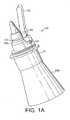
- FIGURE 1Ais a perspective view of a pin-less socket in accordance with a first embodiment of the present invention with a wafer cone inserted therein.
- FIGURE 1 Bis a cross sectional view of two pin-less sockets as shown in FIGURE 1A with two wafer cones inserted therein.
- FIGURE 2Ais a perspective view of another pin-less socket in accordance with a second embodiment of the present invention.
- FIGURE 2Bis a cross sectional view of two pin-less sockets as shown in FIGURE 2A and showing an accompanying spring mechanism.
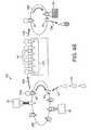
- FIGURE 3is a simplified schematic of a single-loop manufacturing system including pin-less sockets of the present invention.
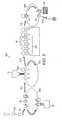
- FIGURES 4A and 4Bare simplified schematics of two variations of multi-loop manufacturing systems including pin-less sockets of the present invention.
- FIGURE 5is another simplified schematic of yet another relatively complex multi-loop manufacturing system including pin-less sockets of the present invention.
- FIGURE 1Ais a perspective view of a pin-less socket 10 in accordance with a first embodiment of the present invention.
- the pin-less socket 10is shown with a wafer cone 100 inserted therein.
- the pin-less socket 10includes a socket 11 in the form of a truncated section that is conical and hollow.
- the socketis smooth and shaped to accept the bottom half of the wafer cone 100. It should be understood that wafer cones are fabricated in standard sizes that deviate very little cone to cone. Accordingly, the bottom half of wafer cone 100 may snugly fit into the socket 11 even with minor cone variations.
- the wafer cone 100is held in place via a hook 13 that includes a hinge 14.
- An O-ring 12 located within a groove 12asurrounds the outside of the socket 11 to cause compression of the hook 13. Compression of the hook 13 causes one or more teeth (shown as 13a in FIGURE 1B ) to grip the tapered end of the wafer cone 100. A stop pin 15 limits the compression of the teeth that gives an end position of the hook. It should be noted that the tapered end of the cone is typically thicker than the rest of the cone. Due to this relative increased thickness, any damage to the cone is minimized.
- FIGURE 1Bshows a cross sectional view of two pin-less sockets 10 as shown in FIGURE 1A with two wafer cones 100. From the FIGURE 1B cross-section, teeth 13a can be seen. It should be understood that this inverted position of the wafer cone 100 is considered to be a preferred manner of presenting the wafer cone 100 for spray coating from below. In such manner of coating, a more even distribution of spray coating (e.g., liquid chocolate) is possible with minimal over spray concerns.
- the hook 13is normally in a compressed position by O-ring 12 or some similar circumferentially placed spring. Release of the wafer cone 100 is accomplished via movement of the hook 13 such that teeth 13a disengage from the wafer cone 100.
- Movement of the hook 13may be facilitated in any known manner without straying from the intended scope of the present invention including the use of pistons, cams, or similar electromechanical mechanisms (not shown).
- a series of pin-less sockets 10 and associated wafer cones 100can be held as shown within a flexible conveyor belt 200 to form part of an assembly line system.
- the present inventionis advantageous in that the same pin-less socket 10 may form an integral part of many different such assembly line systems.
- FIGURE 2Ais a perspective view of a pin-less socket 20 in accordance with a second embodiment of the present invention.
- the pin-less socket 20is shown without any wafer cone inserted therein, though such wafer cone insertion is identical to that shown in regard to FIGURES 1A and 1B .
- the pin-less socket 20includes a socket 21 in the form of a truncated section that is conical, hollow, and smoothly shaped to accept the bottom half of a wafer cone that is held in place via a hook 23 that includes a hinge 24.
- no circumferential compression mechanismis used.
- the hook 23includes a section 23a modified to accept a spring (shown as 23b in FIGURE 2B ) to provide a lever-type action in order to cause compression of the hook 23.
- Lever-type action of the hook 23causes one or more teeth (shown as 23c in FIGURE 2B ) to grip the tapered end of a wafer cone.
- a stop pin 25limits the compression of the teeth that gives an end position of the hook.
- FIGURE 2Bshows a cross sectional view of two pin-less sockets 20 as shown in FIGURE 2A .
- teeth 23ccan be clearly seen as the wafer cones have been omitted for clarity.
- This inverted position of a wafer coneis considered to be a preferred orientation to enable spray coating from below because a more even distribution of spray coating (e.g., liquid chocolate) is possible with minimal over spray concerns.
- the hook 23is normally in an engaged position by action of the spring 23b. Disengagement of the hook 23 is accomplished via lever-type movement of the hook 23 to counter the force of the spring 23b such that teeth 23c disengage from a wafer cone inserted therein (not shown for purposes of clarity).
- the use of the spring 23ballows a stronger, linear spring force and reduced friction.
- lever-type movement of the hook 23may be facilitated in any known manner without straying from the intended scope of the present invention including the use of pistons, cams, or similar electromechanical mechanisms (not shown).
- a series of pin-less sockets 20 and associated wafer conescan be held as shown within a flexible conveyor belt 200 to form part of an assembly line system.
- this arrangement in accordance with the present inventionwould require a spring retention mechanism 201 located on the belt 200.
- the spring retention mechanism 201could be formed integrally with the socket 21 by adding wider flanges on the socket 21.
- the present inventionis advantageous in that the same pin-less socket 20 may form an integral part of many different such assembly line systems.
- FIGURES 3 , 4A , 4B , and 5are simplified schematics of a various manufacturing systems in accordance with the present invention incorporating pin-less sockets of the present invention as shown in FIGURES 1A through 2B .
- pin-less socket version 10 or 20may be used within the systems shown in FIGURES 3 , 4A , 4B , and 5 and various embodiments of the pin-less sockets 10, 20 may be possible without straying from the intended scope of the present invention.
- the schematics of FIGURES 3 , 4A , 4B , and 5are simplified for purposes of illustrative clarity and therefore shown without regard to the specific detail of the pin-less socket of the present invention as such details have been discussed above.
- FIGURES 3 , 4A , 4B , and 5are shown as systems to produce ball-top ice cream cones.
- the systems illustratedinclude both simpler ones that translate into less capital cost for a small assembly line with perhaps low volume and more complex ones (e.g., 3 or more conveyors) that translate into a higher capacity line. Any such system may clearly benefit from the incorporation of the inventive pin-less socket.
- FIGURE 3is a simplified schematic of a single-loop manufacturing system 300 including pin-less sockets 30 of the present invention.
- FIGURE 3includes a mask device 31 that may be of a heated trough-type that recycles over-spray for coating wafer cones 100 via a sprayer 32 from above.
- the wafer cones 100are placed (arrow 501 ) either manually or via an automated manner such as shown by DE 20209984 using stacked cones into respective pin-less sockets 30 that are situated within a conveyor belt 200 that is shown rotating counter-clockwise.
- the conveyor belt 200may be any known carrier mechanism so long as such mechanism is capable of supporting the pin-less sockets 30.
- the wafer cones 100are first spray coated from above by the sprayer 32 with a chocolate coating in a manner well known in the art using or via the mask device 31.
- the coated wafer cone 100is then moved along the conveyor belt 200 where the wafer cone 100 is filled with a semi-frozen confection (e.g., ice cream) via filler 33 in a manner well known in the art in order to form a ball-top 100a.
- the filled wafer cone 100is then moved along the conveyor belt 200 to an area for cooling that includes a hardening tunnel 34.
- the filled and frozen wafer cone 100is then moved along the conveyor belt 200 to a dipping area that includes a dipping bin 35.
- the dipping bin 35may include more than one coating bin (not shown) that, for example, would add an outer layer of chocolate and subsequently an outer layer of nuts.
- the finished wafer cone 100is then released (arrow 502) and packaged (not shown) in a manner well known in the art. It should be understood that a mechanism such as a cam, piston, lever, or similar mechanical device (not shown) is to be used to disengage the wafer cone 100 from engagement within the pin-less socket 30. While only a few pin-less sockets 30 are shown, it should be readily apparent that such sockets are spaced evenly along the entirety of the conveyor belt 200.
- FIGURES 4A and 4Bshow multi-loop assembly line systems 401, 402 in accordance with the present invention and include hardening tunnels 40 that can be any non-dedicated hardening tool commonly known throughout the art.
- FIGURE 4Aincludes three assembly loops.
- wafer cones 100are placed (arrow 503 ) either manually or via an automated manner such as shown by DE 20209984 using stacked cones onto a conveyor belt 200.
- the wafer cones 100are first spray coated from above by a sprayer 32 with a chocolate coating in a manner well known in the art using or via a mask device 31.
- a mask device 31may be of a heated trough-type that recycles over spray.
- the wafer cone 100is then filled with a semi-frozen confection (e.g., ice cream) via filler 33 in a manner well known in the art in order to form a ball-top 100a.
- a semi-frozen confectione.g., ice cream
- the filled wafer cone 100is then transferred (arrow 504) via any known manner of automated "pick and place” mechanics to a second assembly loop that includes a hardening tunnel 40.
- the hardening tunnel 40can be any non-dedicated hardening tool commonly known throughout the art.
- the filled and frozen wafer cone 100is then transferred (arrow 505) via any known manner of automated "pick and place” mechanics to a third assembly loop that includes a conveyor belt 200 with multiple pin-less sockets 30 and a dipping bin 35.
- the dipping bin 35may include more than one coating bin (not shown) that, for example, would add an outer layer of chocolate and subsequently an outer layer of nuts.
- the finished wafer cone 100is then released (arrow 506) and packaged (not shown) in a manner well known in the art.
- a mechanismsuch as a cam, piston, lever, or similar mechanical device is to be used to disengage the wafer cone 100 from engagement within the pin-less socket 30.
- Each of the three assembly loopsare shown as simplified rotating conveyor belts 200. While only a few pin-less sockets 30 are shown, it should be readily apparent that such sockets are spaced evenly along the entirety of the conveyor belt 200 of the third assembly loop.
- FIGURE 4Bis another embodiment of a multi-loop manufacturing system in accordance with the present invention.
- FIGURE 4Bdiffers from FIGURE 4A in that coating of the wafer cones 100 occurs from below while the wafer cones 100 are held in place by pin-less sockets 30.
- the wafer cones 100are placed (arrow 507) either manually or in an automated manner using stacked cones into respective pin-less sockets 30 that are situated within a conveyor belt 200.
- the wafer cones 100are first spray coated from below with a chocolate coating in a manner well known in the art using a sprayer 32.
- the wafer cone 100is then moved along the conveyor belt 200 and filled with a semi-frozen confection (e.g., ice cream) via filler 33 in a manner well known in the art in order to form a ball-top 100a.
- a mechanismsuch as a cam, piston, lever, or similar mechanical device would be used to disengage the wafer cone 100 from engagement within the pin-less socket 30.
- the wafer cone 100is then transferred (arrow 508) via any known manner of automated "pick and place" mechanics to a cooling area that includes a hardening tunnel 40.
- the hardening tunnel 40can be any non-dedicated hardening tool commonly known throughout the art.
- the wafer coneis then transferred (arrow 509) via "pick and place” mechanisms or the like to a dipping area that includes a conveyor belt 200 with multiple pin-less sockets 30 and a dipping bin 35.
- the dipping bin 35may include more than one coating bin (not shown) that, for example, would add an outer layer of chocolate and subsequently an outer layer of nuts.
- the finished wafer cone 100is then released (arrow 510) and packaged (not shown) in a manner well known in the art in conjunction with a release mechanism (not shown) as mentioned above.
- Each assembly loopis shown as a simplified rotating conveyor belt 200. While only a few pin-less sockets 30 are shown in each of the first and third loops, it should be readily apparent that such pin-less sockets are spaced evenly along the entirety of the conveyor belts 200.
- FIGURE 5shows yet another embodiment of a multi-loop manufacturing system in accordance with the present invention.
- four distinct loopsare shown that separate the chocolate coating, ice cream filling, hardening, and nut dip stages.
- the assembly loops related to filling and hardeningcan be made via dedicated filling and hardening mechanisms well known in the art. Separating such stages into distinct loops helps to increase potential manufacturing volume.
- wafer cones 100are placed (arrow 511) into pin-less sockets 30 either manually or in an automated manner such as shown by DE 20209984 using stacked cones onto a conveyor belt 200 that rotates counter clockwise.
- the wafer cones 100then travel along the conveyor belt 200 and are spray coated from below with a chocolate coating in a manner well known in the art using a sprayer 32. After coating, the wafer cone 100 within its respective pin-less socket 30 is moved along the path of the conveyor belt 200 to an area where the wafer cone 100 is then transferred (arrow 512) via any known manner of automated "pick and place” mechanics to a filling second assembly loop that rotates clockwise (i.e., opposite the first loop) and includes a filler 33. It should be understood that a mechanism such as a cam, piston, lever, or similar mechanical device (not shown) is to be used to disengage the wafer cone 100 from engagement within the pin-less socket 30.
- a mechanismsuch as a cam, piston, lever, or similar mechanical device (not shown) is to be used to disengage the wafer cone 100 from engagement within the pin-less socket 30.
- the filler 33fills the wafer cone 100 with a semi-frozen confection (e.g., ice cream) in a manner well known in the art in order to form a ball-top 100a.
- a semi-frozen confectione.g., ice cream
- the wafer cone 100then transferred (arrow 513) via any known manner of automated "pick and place” mechanics to a cooling area that includes a hardening tunnel 40.
- the wafer conecontinues via "pick and place” mechanics (arrow 514) to a dipping area that may include more than one coating bin 35 that, for example, would add an outer layer of chocolate and subsequently an outer layer of nuts.
- the finished wafer cone 100is then released (arrow 515) and packaged (not shown) in a manner well known in the art.
- any mechanismsuch as a cam, piston, lever, or similar mechanical device (not shown) is to be used to disengage the wafer cone 100 from engagement within the pin-less socket 30 .
- any mechanismsuch as a cam, piston, lever, or similar mechanical device (not shown) is to be used to disengage the wafer cone 100 from engagement within the pin-less socket 30 .
- a cam, piston, lever, or similar mechanical deviceis to be used to disengage the wafer cone 100 from engagement within the pin-less socket 30 .
- pin-less sockets 30are shown, such sockets are spaced evenly along the entirety of the conveyor belt 200.
Landscapes
- Life Sciences & Earth Sciences (AREA)
- Chemical & Material Sciences (AREA)
- Engineering & Computer Science (AREA)
- Food Science & Technology (AREA)
- Polymers & Plastics (AREA)
- Confectionery (AREA)
- Container, Conveyance, Adherence, Positioning, Of Wafer (AREA)
Description
- The invention relates to manipulation of frozen confections along a continuously moving manufacturing line. More specifically, the present invention involves a pin-less socket that grips such frozen confections, a method of gripping with such sockets, and a manufacturing system that utilizes such sockets.
- In the art of manufacturing frozen confections such as ice cream cones, a moving assembly line is used to continuously process the confections. In the instance of ball-top ice cream cones, a wafer cone is provided by some means and manner into a fixed position on the assembly line. Often, hand placement of the wafer cones occurs by a human operator. Alternatively, the human operator may place stacked wafer cones within a de-stacking mechanism that assists in automating the initial phase of frozen confection manufacture. The wafer cones are commonly held within an upright position via some tray mechanism or truncated cone holder. The wafer cones are normally coated on their interiors with a liquid chocolate in order to provide a moisture barrier from subsequent filling with a semi-frozen product - e.g., ice cream. The chocolate coating is typically sprayed from above into the upright wafer cones. Extrusion nozzles are used to fill each wafer cone with the semi-frozen product as the wafer cones move into selected placement along the assembly line. The wafer cone filled with dry-coated, semi-frozen product is then moved along the assembly line into a hardening chamber. Further downstream, a dry coating apparatus is placed above the assembly line for covering the semi-frozen product with ground nuts or similar edible material. Subsequently, the frozen confections are packaged into wrappers and boxed for shipment and sale to the ultimate end-user in a manner well known in the art.
- While such manufacturing of frozen confections has existed for a long time in the art, there has been room for improvement. Such needs are clear when wastage is considered. Specifically, spraying of a vertically oriented wafer cone from above often leads to overspray and wastage of the chocolate liquid. Moreover, the chocolate liquid tends to pool at the bottom of the wafer cone, thus often requiring an excessive amount of spray to evenly coat the wafer cone's interior. As well, dry coating from above via sprinkling of nuts or other edible material often results in uneven coating and related wastage of such dry coating that does not readily stick to the semi-solid product. Due to food safety concerns, it is often not possible to reuse the chocolate liquid overspray or unapplied dry coating materials. Some efforts in the art have been made to alleviate the need to maintain the wafer cone within an upright position to thereby reduce such wastage.
US Patent 3,985,223 shows one such example of an upright gripper.US-A-2 334 654 discloses a method and an apparatus for making frozen confections. - There exist known efforts in the manufacture of ball-top cones to provide an assembly line with mechanisms that pivotably present the wafer cone in a movable position. Such mechanisms that hold the wafer cone in a moveable position are commonly referred to as grippers. In such movable position, the wafer cone may be presented along the assembly line in an inverted position and coated with a liquid chocolate spray from below. In order to overcome the undesirable effects of moisture migrating from a relatively moist ice cream material into a relatively dry cone, the frozen confection industry has provided a coating layer between the cone and ice cream to prevent migration of such moisture. The standard coating layer that has been used by the industry is a chocolate product that is vegetable oil based and thus provides a relatively water-impermeable moisture barrier. In manufacture of the ice cream product, the cone is coated by some form of spray applied to the interior of the cone prior to introduction of the ice cream in order to maintain the crispiness of the cone.
- Spraying the liquid chocolate from below allows the spray to be forced well into the cone whereby gravity provides for a secondary movement of the spray down the interior of the cone towards the rim. The movable cone may then swivel into an upright position to be filled from above with the semi-frozen product. Thereafter, the movable cone may then again swivel to place the ball-top in a downward position such that the movable cone may be dipped into a bin or tray holding the dry coating of choice. The moveable cone would then continue along the assembly line to the hardening chamber and be packaged in a known manner as discussed above. There are commonly three different types of gripper mechanisms for pivotably presenting a wafer cone.
- One such known example is a pin gripper that utilizes a skewer-type of arrangement including a pin used to puncture and hold the movable cone rotatably about the pin. While pin grippers positively hold the wafer cone, they suffer from drawbacks that include both increased cone breakage and creating two holes through the wafer. The holes in the wafer are also through the chocolate layer and underlying ice cream product. This often reduces product shelf life as the holes provide a path for moisture to migrate from the ice cream to the wafer and thereby soften or otherwise reduce the wafer crispness.
- Another such example is a pin-less gripper with a positive opening that utilizes a relatively complex clamp and spring arrangement to hold the movable cone. The mechanical complexity involved in such an arrangement reduces access for cleaning surfaces and as such represents a food safety concern.
- Another such example is a pin-less gripper with a passive opening shown by
EP 0925721 which utilizes a pressure-fit arrangement to hold the movable cone. Such a passive manner of gripping does not provide a secure holding of the wafer or needs a strong pressure on the wafer that increases the level of breakage. This leads to premature release of the wafer cone and significant wastage problems. - None of such gripping arrangements provides the necessary holding power in contemporary high-speed assembly lines. Further, many such holding arrangements often lead to damaging effects on the cones and can lead to total wastage of a broken or otherwise unusable product. Still further, the known mechanisms are relatively complex and therefore tend to be mechanically unreliable and require much maintenance.
- The object of the invention is to remedy the drawbacks set out above by proposing a pin-less socket apparatus in which a wafer cone is securely held so as to improve a frozen confection method of assembly and system incorporating such apparatus and method.
- One embodiment of the invention involves a pin-less socket apparatus including a socket for accepting a conical food product therein, the socket having a groove located at an outer periphery of the socket, a hinge located on an outside of the socket, a hook having one or more teeth, the hook movably attached to the socket via the hinge, a compression means for holding the hook in place against the socket, the compression means located within the groove.
- Another embodiment of the invention involves a manufacturing system for assembling a frozen confection including a coating means for coating a wafer cone with a moisture-resistant layer, a filling station having a filler for inserting a semi-frozen confection into the wafer cone, a cooling station for accepting the wafer cone with the semi-frozen confection and including a hardening tunnel for freezing the wafer cone and the semi-frozen confection, a dipping station including more than one pin-less socket apparatus for accepting the wafer cone and moving the wafer cone through a dipping bin, the socket apparatus including a socket for accepting a conical food product therein, the socket having a groove located at an outer periphery of the socket, a hinge located on an outside of the socket, a hook having one or more teeth, the hook movably attached to the socket via the hinge, and a compression means for holding the hook in place against the socket, the compression means located within the groove.
FIGURE 1A is a perspective view of a pin-less socket in accordance with a first embodiment of the present invention with a wafer cone inserted therein.FIGURE 1 B is a cross sectional view of two pin-less sockets as shown inFIGURE 1A with two wafer cones inserted therein.FIGURE 2A is a perspective view of another pin-less socket in accordance with a second embodiment of the present invention.FIGURE 2B is a cross sectional view of two pin-less sockets as shown inFIGURE 2A and showing an accompanying spring mechanism.FIGURE 3 is a simplified schematic of a single-loop manufacturing system including pin-less sockets of the present invention.FIGURES 4A and4B are simplified schematics of two variations of multi-loop manufacturing systems including pin-less sockets of the present invention.FIGURE 5 is another simplified schematic of yet another relatively complex multi-loop manufacturing system including pin-less sockets of the present invention.FIGURE 1A is a perspective view of apin-less socket 10 in accordance with a first embodiment of the present invention. Thepin-less socket 10 is shown with awafer cone 100 inserted therein. Thepin-less socket 10 includes asocket 11 in the form of a truncated section that is conical and hollow. The socket is smooth and shaped to accept the bottom half of thewafer cone 100. It should be understood that wafer cones are fabricated in standard sizes that deviate very little cone to cone. Accordingly, the bottom half ofwafer cone 100 may snugly fit into thesocket 11 even with minor cone variations. Thewafer cone 100 is held in place via ahook 13 that includes ahinge 14. An O-ring 12 located within agroove 12a surrounds the outside of thesocket 11 to cause compression of thehook 13. Compression of thehook 13 causes one or more teeth (shown as13a inFIGURE 1B ) to grip the tapered end of thewafer cone 100. Astop pin 15 limits the compression of the teeth that gives an end position of the hook. It should be noted that the tapered end of the cone is typically thicker than the rest of the cone. Due to this relative increased thickness, any damage to the cone is minimized.FIGURE 1B shows a cross sectional view of twopin-less sockets 10 as shown inFIGURE 1A with twowafer cones 100. From theFIGURE 1B cross-section,teeth 13a can be seen. It should be understood that this inverted position of thewafer cone 100 is considered to be a preferred manner of presenting thewafer cone 100 for spray coating from below. In such manner of coating, a more even distribution of spray coating (e.g., liquid chocolate) is possible with minimal over spray concerns. Thehook 13 is normally in a compressed position by O-ring 12 or some similar circumferentially placed spring. Release of thewafer cone 100 is accomplished via movement of thehook 13 such thatteeth 13a disengage from thewafer cone 100. Movement of thehook 13 may be facilitated in any known manner without straying from the intended scope of the present invention including the use of pistons, cams, or similar electromechanical mechanisms (not shown). A series ofpin-less sockets 10 and associatedwafer cones 100 can be held as shown within aflexible conveyor belt 200 to form part of an assembly line system. The present invention is advantageous in that the samepin-less socket 10 may form an integral part of many different such assembly line systems.FIGURE 2A is a perspective view of apin-less socket 20 in accordance with a second embodiment of the present invention. For clarity, thepin-less socket 20 is shown without any wafer cone inserted therein, though such wafer cone insertion is identical to that shown in regard toFIGURES 1A and1B . Similar to the first embodiment, thepin-less socket 20 includes asocket 21 in the form of a truncated section that is conical, hollow, and smoothly shaped to accept the bottom half of a wafer cone that is held in place via ahook 23 that includes ahinge 24. In this second embodiment, no circumferential compression mechanism is used. Rather, thehook 23 includes asection 23a modified to accept a spring (shown as23b inFIGURE 2B ) to provide a lever-type action in order to cause compression of thehook 23. Lever-type action of thehook 23 causes one or more teeth (shown as23c inFIGURE 2B ) to grip the tapered end of a wafer cone. Astop pin 25 limits the compression of the teeth that gives an end position of the hook.FIGURE 2B shows a cross sectional view of twopin-less sockets 20 as shown inFIGURE 2A . From theFIGURE 2B cross-section,teeth 23c can be clearly seen as the wafer cones have been omitted for clarity. As before, it should be understood that this inverted position of a wafer cone is considered to be a preferred orientation to enable spray coating from below because a more even distribution of spray coating (e.g., liquid chocolate) is possible with minimal over spray concerns. Thehook 23 is normally in an engaged position by action of thespring 23b. Disengagement of thehook 23 is accomplished via lever-type movement of thehook 23 to counter the force of thespring 23b such thatteeth 23c disengage from a wafer cone inserted therein (not shown for purposes of clarity). In contrast to the first embodiment, the use of thespring 23b allows a stronger, linear spring force and reduced friction. As before, such lever-type movement of thehook 23 may be facilitated in any known manner without straying from the intended scope of the present invention including the use of pistons, cams, or similar electromechanical mechanisms (not shown). A series ofpin-less sockets 20 and associated wafer cones can be held as shown within aflexible conveyor belt 200 to form part of an assembly line system. As shown, this arrangement in accordance with the present invention would require aspring retention mechanism 201 located on thebelt 200. However, it should be readily apparent that thespring retention mechanism 201 could be formed integrally with thesocket 21 by adding wider flanges on thesocket 21. Again, the present invention is advantageous in that the samepin-less socket 20 may form an integral part of many different such assembly line systems.- It should be understood that the size and shape of the one or more teeth in either embodiment mentioned above are optimized to have a positive holding of the wafer with no risk of breaking the associated cone.
FIGURES 3 ,4A ,4B , and5 are simplified schematics of a various manufacturing systems in accordance with the present invention incorporating pin-less sockets of the present invention as shown inFIGURES 1A through2B . It should be readily understood that eitherpin-less socket version FIGURES 3 ,4A ,4B , and5 and various embodiments of thepin-less sockets FIGURES 3 ,4A ,4B , and5 are simplified for purposes of illustrative clarity and therefore shown without regard to the specific detail of the pin-less socket of the present invention as such details have been discussed above.FIGURES 3 ,4A ,4B , and5 are shown as systems to produce ball-top ice cream cones. The systems illustrated include both simpler ones that translate into less capital cost for a small assembly line with perhaps low volume and more complex ones (e.g., 3 or more conveyors) that translate into a higher capacity line. Any such system may clearly benefit from the incorporation of the inventive pin-less socket.FIGURE 3 is a simplified schematic of a single-loop manufacturing system 300 includingpin-less sockets 30 of the present invention.FIGURE 3 includes amask device 31 that may be of a heated trough-type that recycles over-spray for coatingwafer cones 100 via asprayer 32 from above. Thewafer cones 100 are placed (arrow501) either manually or via an automated manner such as shown byDE 20209984 using stacked cones into respectivepin-less sockets 30 that are situated within aconveyor belt 200 that is shown rotating counter-clockwise. Theconveyor belt 200 may be any known carrier mechanism so long as such mechanism is capable of supporting thepin-less sockets 30. Thewafer cones 100 are first spray coated from above by thesprayer 32 with a chocolate coating in a manner well known in the art using or via themask device 31. Thecoated wafer cone 100 is then moved along theconveyor belt 200 where thewafer cone 100 is filled with a semi-frozen confection (e.g., ice cream) viafiller 33 in a manner well known in the art in order to form a ball-top 100a. The filledwafer cone 100 is then moved along theconveyor belt 200 to an area for cooling that includes a hardeningtunnel 34. The filled andfrozen wafer cone 100 is then moved along theconveyor belt 200 to a dipping area that includes adipping bin 35. The dippingbin 35 may include more than one coating bin (not shown) that, for example, would add an outer layer of chocolate and subsequently an outer layer of nuts. Thefinished wafer cone 100 is then released (arrow502) and packaged (not shown) in a manner well known in the art. It should be understood that a mechanism such as a cam, piston, lever, or similar mechanical device (not shown) is to be used to disengage thewafer cone 100 from engagement within thepin-less socket 30. While only a fewpin-less sockets 30 are shown, it should be readily apparent that such sockets are spaced evenly along the entirety of theconveyor belt 200.FIGURES 4A and4B show multi-loopassembly line systems tunnels 40 that can be any non-dedicated hardening tool commonly known throughout the art.FIGURE 4A includes three assembly loops. First,wafer cones 100 are placed (arrow503) either manually or via an automated manner such as shown byDE 20209984 using stacked cones onto aconveyor belt 200. Thewafer cones 100 are first spray coated from above by asprayer 32 with a chocolate coating in a manner well known in the art using or via amask device 31. Such amask device 31 may be of a heated trough-type that recycles over spray. Thewafer cone 100 is then filled with a semi-frozen confection (e.g., ice cream) viafiller 33 in a manner well known in the art in order to form a ball-top 100a. The filledwafer cone 100 is then transferred (arrow504) via any known manner of automated "pick and place" mechanics to a second assembly loop that includes a hardeningtunnel 40. In this embodiment, the hardeningtunnel 40 can be any non-dedicated hardening tool commonly known throughout the art. The filled andfrozen wafer cone 100 is then transferred (arrow505) via any known manner of automated "pick and place" mechanics to a third assembly loop that includes aconveyor belt 200 with multiplepin-less sockets 30 and adipping bin 35. As before, the dippingbin 35 may include more than one coating bin (not shown) that, for example, would add an outer layer of chocolate and subsequently an outer layer of nuts. Thefinished wafer cone 100 is then released (arrow506) and packaged (not shown) in a manner well known in the art. As before, it should be understood that a mechanism (not shown) such as a cam, piston, lever, or similar mechanical device is to be used to disengage thewafer cone 100 from engagement within thepin-less socket 30. Each of the three assembly loops are shown as simplifiedrotating conveyor belts 200. While only a fewpin-less sockets 30 are shown, it should be readily apparent that such sockets are spaced evenly along the entirety of theconveyor belt 200 of the third assembly loop.FIGURE 4B is another embodiment of a multi-loop manufacturing system in accordance with the present invention.FIGURE 4B differs fromFIGURE 4A in that coating of thewafer cones 100 occurs from below while thewafer cones 100 are held in place bypin-less sockets 30. Thewafer cones 100 are placed (arrow507) either manually or in an automated manner using stacked cones into respectivepin-less sockets 30 that are situated within aconveyor belt 200. Thewafer cones 100 are first spray coated from below with a chocolate coating in a manner well known in the art using asprayer 32. After coating, thewafer cone 100 is then moved along theconveyor belt 200 and filled with a semi-frozen confection (e.g., ice cream) viafiller 33 in a manner well known in the art in order to form a ball-top 100a. It should be understood that a mechanism such as a cam, piston, lever, or similar mechanical device would be used to disengage thewafer cone 100 from engagement within thepin-less socket 30. Thewafer cone 100 is then transferred (arrow508) via any known manner of automated "pick and place" mechanics to a cooling area that includes a hardeningtunnel 40. Again, the hardeningtunnel 40 can be any non-dedicated hardening tool commonly known throughout the art. After hardening, the wafer cone is then transferred (arrow509) via "pick and place" mechanisms or the like to a dipping area that includes aconveyor belt 200 with multiplepin-less sockets 30 and adipping bin 35. As before, the dippingbin 35 may include more than one coating bin (not shown) that, for example, would add an outer layer of chocolate and subsequently an outer layer of nuts. Thefinished wafer cone 100 is then released (arrow510) and packaged (not shown) in a manner well known in the art in conjunction with a release mechanism (not shown) as mentioned above. Each assembly loop is shown as a simplifiedrotating conveyor belt 200. While only a fewpin-less sockets 30 are shown in each of the first and third loops, it should be readily apparent that such pin-less sockets are spaced evenly along the entirety of theconveyor belts 200.FIGURE 5 shows yet another embodiment of a multi-loop manufacturing system in accordance with the present invention. Here, four distinct loops are shown that separate the chocolate coating, ice cream filling, hardening, and nut dip stages. FromFIGURE 5 , it is also clear that the assembly loops related to filling and hardening can be made via dedicated filling and hardening mechanisms well known in the art. Separating such stages into distinct loops helps to increase potential manufacturing volume. Specifically,wafer cones 100 are placed (arrow511) intopin-less sockets 30 either manually or in an automated manner such as shown byDE 20209984 using stacked cones onto aconveyor belt 200 that rotates counter clockwise. Thewafer cones 100 then travel along theconveyor belt 200 and are spray coated from below with a chocolate coating in a manner well known in the art using asprayer 32. After coating, thewafer cone 100 within its respectivepin-less socket 30 is moved along the path of theconveyor belt 200 to an area where thewafer cone 100 is then transferred (arrow512) via any known manner of automated "pick and place" mechanics to a filling second assembly loop that rotates clockwise (i.e., opposite the first loop) and includes afiller 33. It should be understood that a mechanism such as a cam, piston, lever, or similar mechanical device (not shown) is to be used to disengage thewafer cone 100 from engagement within thepin-less socket 30. Thefiller 33 fills thewafer cone 100 with a semi-frozen confection (e.g., ice cream) in a manner well known in the art in order to form a ball-top 100a. After filling, thewafer cone 100 then transferred (arrow513) via any known manner of automated "pick and place" mechanics to a cooling area that includes a hardeningtunnel 40. Subsequent to hardening, the wafer cone continues via "pick and place" mechanics (arrow514) to a dipping area that may include more than onecoating bin 35 that, for example, would add an outer layer of chocolate and subsequently an outer layer of nuts. Thefinished wafer cone 100 is then released (arrow515) and packaged (not shown) in a manner well known in the art. As before, it should be readily apparent that any mechanism such as a cam, piston, lever, or similar mechanical device (not shown) is to be used to disengage thewafer cone 100 from engagement within thepin-less socket 30. Again, it should be understood that while only a fewpin-less sockets 30 are shown, such sockets are spaced evenly along the entirety of theconveyor belt 200.- The above-described embodiments of the present invention are intended to be examples only. Alterations, modifications and variations may be effected to the particular embodiments by those of skill in the art without departing from the scope of the invention, which is defined solely by the claims appended hereto.
Claims (19)
- Claims. A pin-less socket apparatus, said apparatus comprising:a socket for accepting a conical food product therein;a hinge located on an outside of said socket;a hook having one or more teeth, said hook movably attached to said socket via said hinge; anda force means for holding said hook in place within said socket in order to retain said conical food product.
- The apparatus as claimed inClaim 1 wherein
said socket includes a recess located at an outer periphery thereof and said hook includes a notch such that said recess and said notch form an annular groove and said force means is located within said groove. - The pin-less socket apparatus as claimed inClaim 2 wherein said socket has a truncated cone shape.
- The pin-less socket apparatus as claimed inClaim 3 wherein said force means is an O-ring having elastic properties.
- The pin-less socket apparatus as claimed inClaim 3 wherein said force means is a coil-spring.
- The pin-less socket apparatus as claimed inClaim 2 wherein said recess includes an opening corresponding in shape and size in order to allow movement of said one or more teeth therethrough.
- The pin-less socket apparatus as claimed inClaim 1 wherein
said socket includes a recess located at an outer periphery thereof and said hook includes a notch such that said force means is connectable to said notch in a manner so as to provide lever-type movement of said hook relative to said hinge. - The pin-less socket apparatus as claimed inClaim 7 wherein said force means is a linear spring connected at one end to said hook at said notch and at another end to a fixed point.
- The pin-less socket apparatus as claimed inClaim 8 wherein said recess includes an opening corresponding in shape and size in order to allow movement of said one or more teeth therethrough.
- A manufacturing system for assembling a frozen confection, said system comprising:a coating area including a coating means for coating a wafer cone with a moisture-resistant layer;a filling area having a filler for inserting a semi-frozen confection into said wafer cone; anda cooling area for accepting said wafer cone with said semi-frozen confection and including a hardening tunnel for freezing said wafer cone and said semi-frozen confection;wherein at least one of said coating, filling, and cooling areas include more than one pin-less socket apparatus, said socket apparatus including a socket for accepting said wafer cone therein, a hinge located on an outside of said socket, a hook having one or more teeth, said hook movably attached to said socket via said hinge, and a force means for holding said one or more teeth in place within said socket so as to retain said conical food product with said socket.
- The system as claimed in Claim10 wherein said system further includes a dipping area for moving said wafer cone through a dipping bin, wherein said dipping area includes more than one said pin-less socket apparatus, said socket apparatus including said socket for accepting said wafer cone therein, said hinge located on said outside of said socket, said hook having said one or more teeth, said hook movably attached to said socket via said hinge, and said force means for holding said one or more teeth in place within said socket so as to retain said conical food product with said socket.
- The system as claimed in Claim11 wherein said socket includes a recess located at an outer periphery thereof and said hook includes a notch such that said recess and said notch form an annular groove and said force means is located within said groove.
- The system as claimed inClaim 11 wherein said socket includes a recess located at an outer periphery thereof and said hook includes a notch such that said force means is connectable to said notch in a manner so as to provide lever-type movement of said hook relative to said hinge.
- The system as claimed inClaim 11 wherein said coating area, said filling area, said cooling area, and said dipping area together form a single assembly loop and said more than one pin-less socket apparatus convey said wafer cone through each of said coating, said filling, said cooling, and said dipping areas.
- The system as claimed inClaim 11 wherein said coating area and said filling area form a first assembly loop, said cooling area forms a second assembly loop, said dipping area forms a third assembly loop, and said more than one pin-less socket apparatus are located within said third assembly loop so as to convey said wafer cone through said dipping area.
- The system as claimed in Claim11 wherein said coating area and said filling area form a first assembly loop, said cooling area forms a second assembly loop, said dipping area forms a third assembly loop, and said more than one pin-less socket apparatus are located within both said first assembly loop and said third assembly loop so as to, correspondingly, convey said wafer cone through coating and filling areas and said dipping area.
- The system as claimed inClaim 11 wherein said coating area forms a first assembly loop, said filling area form a second assembly loop, said cooling area forms a third assembly loop, said dipping area forms a fourth assembly loop, and said more than one pin-less socket apparatus are located within both said first assembly loop and said fourth assembly loop so as to, correspondingly, convey said wafer cone through said coating and said dipping areas.
- The system as claimed inClaim 11 wherein said coating means coats said wafer cone from below said wafer cone when said wafer cone is held in an inverted position by one said pin-less socket apparatus.
- The system as claimed inClaim 11 wherein said coating means coats said wafer cone from above said wafer cone when said wafer cone is held in an upright position by one said pin-less socket apparatus.
Applications Claiming Priority (2)
| Application Number | Priority Date | Filing Date | Title |
|---|---|---|---|
| US11/136,358US7730831B2 (en) | 2005-05-25 | 2005-05-25 | Pin-less socket for frozen confections |
| PCT/EP2006/000899WO2006125477A1 (en) | 2005-05-25 | 2006-02-02 | Pin-less socket for frozen confections |
Publications (2)
| Publication Number | Publication Date |
|---|---|
| EP1887878A1 EP1887878A1 (en) | 2008-02-20 |
| EP1887878B1true EP1887878B1 (en) | 2009-09-09 |
Family
ID=36113592
Family Applications (1)
| Application Number | Title | Priority Date | Filing Date |
|---|---|---|---|
| EP06704235ANot-in-forceEP1887878B1 (en) | 2005-05-25 | 2006-02-02 | Pin-less socket for frozen confections |
Country Status (8)
| Country | Link |
|---|---|
| US (1) | US7730831B2 (en) |
| EP (1) | EP1887878B1 (en) |
| AR (1) | AR053490A1 (en) |
| AT (1) | ATE442053T1 (en) |
| AU (1) | AU2006251441B2 (en) |
| DE (1) | DE602006009100D1 (en) |
| MX (1) | MX2007013863A (en) |
| WO (1) | WO2006125477A1 (en) |
Families Citing this family (12)
| Publication number | Priority date | Publication date | Assignee | Title |
|---|---|---|---|---|
| JP6971311B2 (en) | 2016-06-16 | 2021-11-24 | コールドスナップ コーポレイション | System for providing one cup of frozen confectionery |
| US10334868B2 (en) | 2016-06-16 | 2019-07-02 | Sigma Phase, Corp. | System for providing a single serving of a frozen confection |
| US10426180B1 (en) | 2016-06-16 | 2019-10-01 | Sigma Phase, Corp. | System for providing a single serving of a frozen confection |
| JP7016143B2 (en)* | 2017-11-07 | 2022-02-04 | 株式会社愛産製作所 | Frozen dessert manufacturing equipment |
| US10543978B1 (en) | 2018-08-17 | 2020-01-28 | Sigma Phase, Corp. | Rapidly cooling food and drinks |
| US11470855B2 (en) | 2018-08-17 | 2022-10-18 | Coldsnap, Corp. | Providing single servings of cooled foods and drinks |
| US10612835B2 (en) | 2018-08-17 | 2020-04-07 | Sigma Phase, Corp. | Rapidly cooling food and drinks |
| US11781808B2 (en) | 2019-04-09 | 2023-10-10 | Coldsnap, Corp. | Brewing and cooling a beverage |
| US11337438B2 (en) | 2020-01-15 | 2022-05-24 | Coldsnap, Corp. | Rapidly cooling food and drinks |
| TW202202790A (en) | 2020-06-01 | 2022-01-16 | 美商寇德斯納普公司 | Refrigeration systems for rapidly cooling food and drinks |
| US20210368822A1 (en) | 2020-06-02 | 2021-12-02 | Samuel Messinger | System for producing and manufacturing of frozen confection product and method thereof |
| US11827402B2 (en) | 2021-02-02 | 2023-11-28 | Coldsnap, Corp. | Filling aluminum cans aseptically |
Family Cites Families (11)
| Publication number | Priority date | Publication date | Assignee | Title |
|---|---|---|---|---|
| US280464A (en)* | 1883-07-03 | giffoed | ||
| US1094113A (en)* | 1912-09-06 | 1914-04-21 | Paul Bissen | Well-pipe lifter. |
| US2334654A (en)* | 1941-05-06 | 1943-11-16 | Sportolari Frank | Method of forming coated frozen confections |
| US2719508A (en)* | 1950-03-14 | 1955-10-04 | Drumstick Inc | Holder for cone-shaped confections |
| US3985223A (en) | 1975-09-22 | 1976-10-12 | Fmc Corporation | Universal gripper assembly for frozen confections |
| SE8406107L (en)* | 1984-12-03 | 1986-06-04 | Surtevall Trading Ab | DEVICE FOR LOADING A FORMULA AGAINST A STRAP, AXLE OR SIMILAR |
| EP0925721A3 (en) | 1997-11-28 | 2000-03-29 | Tetra Pak Hoyer A/S | A method of handling ice-cream articles e.g. cornets and gripping aggregate therefor |
| DK174118B1 (en) | 1998-05-01 | 2002-07-01 | Gram As | Pliers for use in picking up ice sticks |
| US6698071B1 (en)* | 2002-02-19 | 2004-03-02 | Homax Products, Inc. | Clip systems and methods for sheet materials |
| DE20209984U1 (en) | 2002-06-27 | 2002-10-17 | TECON Spezialmaschinen GmbH, 41812 Erkelenz | Unstacking device for ice cream cones |
| US7267075B2 (en)* | 2003-10-28 | 2007-09-11 | Norse Dairy Systems, Inc. | Modular and reconfigurable frozen cone confection manufacturing system and method |
- 2005
- 2005-05-25USUS11/136,358patent/US7730831B2/ennot_activeExpired - Fee Related
- 2006
- 2006-02-02EPEP06704235Apatent/EP1887878B1/ennot_activeNot-in-force
- 2006-02-02WOPCT/EP2006/000899patent/WO2006125477A1/ennot_activeApplication Discontinuation
- 2006-02-02MXMX2007013863Apatent/MX2007013863A/enunknown
- 2006-02-02DEDE602006009100Tpatent/DE602006009100D1/ennot_activeExpired - Fee Related
- 2006-02-02AUAU2006251441Apatent/AU2006251441B2/ennot_activeCeased
- 2006-02-02ATAT06704235Tpatent/ATE442053T1/ennot_activeIP Right Cessation
- 2006-05-24ARARP060102172Apatent/AR053490A1/enunknown
Also Published As
| Publication number | Publication date |
|---|---|
| WO2006125477A1 (en) | 2006-11-30 |
| US7730831B2 (en) | 2010-06-08 |
| AR053490A1 (en) | 2007-05-09 |
| AU2006251441B2 (en) | 2012-01-19 |
| ATE442053T1 (en) | 2009-09-15 |
| EP1887878A1 (en) | 2008-02-20 |
| AU2006251441A1 (en) | 2006-11-30 |
| DE602006009100D1 (en) | 2009-10-22 |
| US20060280826A1 (en) | 2006-12-14 |
| MX2007013863A (en) | 2008-01-24 |
Similar Documents
| Publication | Publication Date | Title |
|---|---|---|
| EP1887878B1 (en) | Pin-less socket for frozen confections | |
| US7267075B2 (en) | Modular and reconfigurable frozen cone confection manufacturing system and method | |
| AU645362B2 (en) | Methods and apparatus for creating a gelatin coating | |
| US5511361A (en) | Encapsulation method | |
| US5918765A (en) | Container dispensing systems especially useful for dispensing edible cones | |
| US7513213B2 (en) | Method, apparatus, and system for coating food items | |
| PL214038B1 (en) | Method and apparatus for producing edible fat-based shell for confectioneries and confectioneries produced thereby | |
| US20080149022A1 (en) | Conical shell grasping and retaining apparatus, method for coating inverted conical shells, and modular and reconfigurable frozen cone confection manufacturing system and method | |
| CA2508187C (en) | Pin-less socket for frozen confections | |
| AU2008293708B2 (en) | Apparatus and method of applying edible pearlescent coating to a food product | |
| US2282661A (en) | Device for handling and dipping confections | |
| US20090047393A1 (en) | System for combining ice cream and coatings | |
| HUT74496A (en) | Coating for ice confections | |
| US3283471A (en) | Automatic packing apparatus | |
| CA2450086C (en) | Destacking device for ice-cream cones | |
| US2336649A (en) | Apparatus for forming coated frozen confections | |
| EP1858343A1 (en) | Method and apparatus for decorating confectioneries | |
| WO2012084505A1 (en) | Edible receptacles for frozen confections | |
| CA2484723C (en) | Conical shell grasping and retaining apparatus, method for coating inverted conical shells, and modular and reconfigurable frozen cone confection manufacturing system and method | |
| CN109414812A (en) | Station for depositing strips of material onto top and/or bottom | |
| EP0631934A1 (en) | Drop-feed apparatus, for example for filling containers and the related method | |
| DK9300064U3 (en) | Chocolate coating apparatus for confectionery products | |
| CA2486018A1 (en) | Method, apparatus, and system for coating food items | |
| NZ248780A (en) | Coating a product - vacuum tubes hold inverted product |
Legal Events
| Date | Code | Title | Description |
|---|---|---|---|
| PUAI | Public reference made under article 153(3) epc to a published international application that has entered the european phase | Free format text:ORIGINAL CODE: 0009012 | |
| 17P | Request for examination filed | Effective date:20071227 | |
| AK | Designated contracting states | Kind code of ref document:A1 Designated state(s):AT BE BG CH CY CZ DE DK EE ES FI FR GB GR HU IE IS IT LI LT LU LV MC NL PL PT RO SE SI SK TR | |
| 17Q | First examination report despatched | Effective date:20080530 | |
| DAX | Request for extension of the european patent (deleted) | ||
| GRAP | Despatch of communication of intention to grant a patent | Free format text:ORIGINAL CODE: EPIDOSNIGR1 | |
| GRAS | Grant fee paid | Free format text:ORIGINAL CODE: EPIDOSNIGR3 | |
| GRAA | (expected) grant | Free format text:ORIGINAL CODE: 0009210 | |
| AK | Designated contracting states | Kind code of ref document:B1 Designated state(s):AT BE BG CH CY CZ DE DK EE ES FI FR GB GR HU IE IS IT LI LT LU LV MC NL PL PT RO SE SI SK TR | |
| REG | Reference to a national code | Ref country code:GB Ref legal event code:FG4D | |
| REG | Reference to a national code | Ref country code:CH Ref legal event code:EP | |
| REG | Reference to a national code | Ref country code:IE Ref legal event code:FG4D | |
| REF | Corresponds to: | Ref document number:602006009100 Country of ref document:DE Date of ref document:20091022 Kind code of ref document:P | |
| PG25 | Lapsed in a contracting state [announced via postgrant information from national office to epo] | Ref country code:FI Free format text:LAPSE BECAUSE OF FAILURE TO SUBMIT A TRANSLATION OF THE DESCRIPTION OR TO PAY THE FEE WITHIN THE PRESCRIBED TIME-LIMIT Effective date:20090909 Ref country code:LT Free format text:LAPSE BECAUSE OF FAILURE TO SUBMIT A TRANSLATION OF THE DESCRIPTION OR TO PAY THE FEE WITHIN THE PRESCRIBED TIME-LIMIT Effective date:20090909 Ref country code:SE Free format text:LAPSE BECAUSE OF FAILURE TO SUBMIT A TRANSLATION OF THE DESCRIPTION OR TO PAY THE FEE WITHIN THE PRESCRIBED TIME-LIMIT Effective date:20090909 | |
| NLV1 | Nl: lapsed or annulled due to failure to fulfill the requirements of art. 29p and 29m of the patents act | ||
| LTIE | Lt: invalidation of european patent or patent extension | Effective date:20090909 | |
| PG25 | Lapsed in a contracting state [announced via postgrant information from national office to epo] | Ref country code:PL Free format text:LAPSE BECAUSE OF FAILURE TO SUBMIT A TRANSLATION OF THE DESCRIPTION OR TO PAY THE FEE WITHIN THE PRESCRIBED TIME-LIMIT Effective date:20090909 Ref country code:NL Free format text:LAPSE BECAUSE OF FAILURE TO SUBMIT A TRANSLATION OF THE DESCRIPTION OR TO PAY THE FEE WITHIN THE PRESCRIBED TIME-LIMIT Effective date:20090909 Ref country code:LV Free format text:LAPSE BECAUSE OF FAILURE TO SUBMIT A TRANSLATION OF THE DESCRIPTION OR TO PAY THE FEE WITHIN THE PRESCRIBED TIME-LIMIT Effective date:20090909 Ref country code:SI Free format text:LAPSE BECAUSE OF FAILURE TO SUBMIT A TRANSLATION OF THE DESCRIPTION OR TO PAY THE FEE WITHIN THE PRESCRIBED TIME-LIMIT Effective date:20090909 | |
| PG25 | Lapsed in a contracting state [announced via postgrant information from national office to epo] | Ref country code:CY Free format text:LAPSE BECAUSE OF FAILURE TO SUBMIT A TRANSLATION OF THE DESCRIPTION OR TO PAY THE FEE WITHIN THE PRESCRIBED TIME-LIMIT Effective date:20090909 | |
| PG25 | Lapsed in a contracting state [announced via postgrant information from national office to epo] | Ref country code:ES Free format text:LAPSE BECAUSE OF FAILURE TO SUBMIT A TRANSLATION OF THE DESCRIPTION OR TO PAY THE FEE WITHIN THE PRESCRIBED TIME-LIMIT Effective date:20091220 Ref country code:EE Free format text:LAPSE BECAUSE OF FAILURE TO SUBMIT A TRANSLATION OF THE DESCRIPTION OR TO PAY THE FEE WITHIN THE PRESCRIBED TIME-LIMIT Effective date:20090909 Ref country code:IS Free format text:LAPSE BECAUSE OF FAILURE TO SUBMIT A TRANSLATION OF THE DESCRIPTION OR TO PAY THE FEE WITHIN THE PRESCRIBED TIME-LIMIT Effective date:20100109 Ref country code:CZ Free format text:LAPSE BECAUSE OF FAILURE TO SUBMIT A TRANSLATION OF THE DESCRIPTION OR TO PAY THE FEE WITHIN THE PRESCRIBED TIME-LIMIT Effective date:20090909 Ref country code:PT Free format text:LAPSE BECAUSE OF FAILURE TO SUBMIT A TRANSLATION OF THE DESCRIPTION OR TO PAY THE FEE WITHIN THE PRESCRIBED TIME-LIMIT Effective date:20100111 Ref country code:RO Free format text:LAPSE BECAUSE OF FAILURE TO SUBMIT A TRANSLATION OF THE DESCRIPTION OR TO PAY THE FEE WITHIN THE PRESCRIBED TIME-LIMIT Effective date:20090909 | |
| PG25 | Lapsed in a contracting state [announced via postgrant information from national office to epo] | Ref country code:SK Free format text:LAPSE BECAUSE OF FAILURE TO SUBMIT A TRANSLATION OF THE DESCRIPTION OR TO PAY THE FEE WITHIN THE PRESCRIBED TIME-LIMIT Effective date:20090909 | |
| PG25 | Lapsed in a contracting state [announced via postgrant information from national office to epo] | Ref country code:BE Free format text:LAPSE BECAUSE OF FAILURE TO SUBMIT A TRANSLATION OF THE DESCRIPTION OR TO PAY THE FEE WITHIN THE PRESCRIBED TIME-LIMIT Effective date:20090909 Ref country code:AT Free format text:LAPSE BECAUSE OF FAILURE TO SUBMIT A TRANSLATION OF THE DESCRIPTION OR TO PAY THE FEE WITHIN THE PRESCRIBED TIME-LIMIT Effective date:20090909 | |
| PLBE | No opposition filed within time limit | Free format text:ORIGINAL CODE: 0009261 | |
| STAA | Information on the status of an ep patent application or granted ep patent | Free format text:STATUS: NO OPPOSITION FILED WITHIN TIME LIMIT | |
| PG25 | Lapsed in a contracting state [announced via postgrant information from national office to epo] | Ref country code:DK Free format text:LAPSE BECAUSE OF FAILURE TO SUBMIT A TRANSLATION OF THE DESCRIPTION OR TO PAY THE FEE WITHIN THE PRESCRIBED TIME-LIMIT Effective date:20090909 | |
| 26N | No opposition filed | Effective date:20100610 | |
| REG | Reference to a national code | Ref country code:CH Ref legal event code:PL | |
| GBPC | Gb: european patent ceased through non-payment of renewal fee | Effective date:20100202 | |
| PG25 | Lapsed in a contracting state [announced via postgrant information from national office to epo] | Ref country code:MC Free format text:LAPSE BECAUSE OF NON-PAYMENT OF DUE FEES Effective date:20100301 Ref country code:LI Free format text:LAPSE BECAUSE OF NON-PAYMENT OF DUE FEES Effective date:20100228 Ref country code:GR Free format text:LAPSE BECAUSE OF FAILURE TO SUBMIT A TRANSLATION OF THE DESCRIPTION OR TO PAY THE FEE WITHIN THE PRESCRIBED TIME-LIMIT Effective date:20091210 Ref country code:CH Free format text:LAPSE BECAUSE OF NON-PAYMENT OF DUE FEES Effective date:20100228 | |
| PG25 | Lapsed in a contracting state [announced via postgrant information from national office to epo] | Ref country code:IE Free format text:LAPSE BECAUSE OF NON-PAYMENT OF DUE FEES Effective date:20100202 | |
| PG25 | Lapsed in a contracting state [announced via postgrant information from national office to epo] | Ref country code:DE Free format text:LAPSE BECAUSE OF NON-PAYMENT OF DUE FEES Effective date:20100901 | |
| PG25 | Lapsed in a contracting state [announced via postgrant information from national office to epo] | Ref country code:IT Free format text:LAPSE BECAUSE OF FAILURE TO SUBMIT A TRANSLATION OF THE DESCRIPTION OR TO PAY THE FEE WITHIN THE PRESCRIBED TIME-LIMIT Effective date:20090909 Ref country code:GB Free format text:LAPSE BECAUSE OF NON-PAYMENT OF DUE FEES Effective date:20100202 | |
| PGFP | Annual fee paid to national office [announced via postgrant information from national office to epo] | Ref country code:FR Payment date:20120221 Year of fee payment:7 | |
| PG25 | Lapsed in a contracting state [announced via postgrant information from national office to epo] | Ref country code:BG Free format text:LAPSE BECAUSE OF FAILURE TO SUBMIT A TRANSLATION OF THE DESCRIPTION OR TO PAY THE FEE WITHIN THE PRESCRIBED TIME-LIMIT Effective date:20090909 Ref country code:HU Free format text:LAPSE BECAUSE OF FAILURE TO SUBMIT A TRANSLATION OF THE DESCRIPTION OR TO PAY THE FEE WITHIN THE PRESCRIBED TIME-LIMIT Effective date:20100310 Ref country code:LU Free format text:LAPSE BECAUSE OF NON-PAYMENT OF DUE FEES Effective date:20100202 | |
| PG25 | Lapsed in a contracting state [announced via postgrant information from national office to epo] | Ref country code:TR Free format text:LAPSE BECAUSE OF FAILURE TO SUBMIT A TRANSLATION OF THE DESCRIPTION OR TO PAY THE FEE WITHIN THE PRESCRIBED TIME-LIMIT Effective date:20090909 | |
| REG | Reference to a national code | Ref country code:FR Ref legal event code:ST Effective date:20131031 | |
| PG25 | Lapsed in a contracting state [announced via postgrant information from national office to epo] | Ref country code:FR Free format text:LAPSE BECAUSE OF NON-PAYMENT OF DUE FEES Effective date:20130228 |