EP1886710B1 - Catheter and introducer needle assembly with needle shield - Google Patents
Catheter and introducer needle assembly with needle shieldDownload PDFInfo
- Publication number
- EP1886710B1 EP1886710B1EP07117417.1AEP07117417AEP1886710B1EP 1886710 B1EP1886710 B1EP 1886710B1EP 07117417 AEP07117417 AEP 07117417AEP 1886710 B1EP1886710 B1EP 1886710B1
- Authority
- EP
- European Patent Office
- Prior art keywords
- needle
- canting
- shield assembly
- shield
- canting plate
- Prior art date
- Legal status (The legal status is an assumption and is not a legal conclusion. Google has not performed a legal analysis and makes no representation as to the accuracy of the status listed.)
- Expired - Lifetime
Links
Images


Classifications
- A—HUMAN NECESSITIES
- A61—MEDICAL OR VETERINARY SCIENCE; HYGIENE
- A61M—DEVICES FOR INTRODUCING MEDIA INTO, OR ONTO, THE BODY; DEVICES FOR TRANSDUCING BODY MEDIA OR FOR TAKING MEDIA FROM THE BODY; DEVICES FOR PRODUCING OR ENDING SLEEP OR STUPOR
- A61M5/00—Devices for bringing media into the body in a subcutaneous, intra-vascular or intramuscular way; Accessories therefor, e.g. filling or cleaning devices, arm-rests
- A61M5/178—Syringes
- A61M5/31—Details
- A61M5/32—Needles; Details of needles pertaining to their connection with syringe or hub; Accessories for bringing the needle into, or holding the needle on, the body; Devices for protection of needles
- A61M5/3205—Apparatus for removing or disposing of used needles or syringes, e.g. containers; Means for protection against accidental injuries from used needles
- A61M5/321—Means for protection against accidental injuries by used needles
- A61M5/3243—Means for protection against accidental injuries by used needles being axially-extensible, e.g. protective sleeves coaxially slidable on the syringe barrel
- A61M5/3273—Means for protection against accidental injuries by used needles being axially-extensible, e.g. protective sleeves coaxially slidable on the syringe barrel freely sliding on needle shaft without connection to syringe or needle
- A—HUMAN NECESSITIES
- A61—MEDICAL OR VETERINARY SCIENCE; HYGIENE
- A61M—DEVICES FOR INTRODUCING MEDIA INTO, OR ONTO, THE BODY; DEVICES FOR TRANSDUCING BODY MEDIA OR FOR TAKING MEDIA FROM THE BODY; DEVICES FOR PRODUCING OR ENDING SLEEP OR STUPOR
- A61M25/00—Catheters; Hollow probes
- A61M25/01—Introducing, guiding, advancing, emplacing or holding catheters
- A61M25/06—Body-piercing guide needles or the like
- A61M25/0612—Devices for protecting the needle; Devices to help insertion of the needle, e.g. wings or holders
- A61M25/0618—Devices for protecting the needle; Devices to help insertion of the needle, e.g. wings or holders having means for protecting only the distal tip of the needle, e.g. a needle guard
- A61M25/0625—Devices for protecting the needle; Devices to help insertion of the needle, e.g. wings or holders having means for protecting only the distal tip of the needle, e.g. a needle guard with a permanent connection to the needle hub, e.g. a guiding rail, a locking mechanism or a guard advancement mechanism
- A—HUMAN NECESSITIES
- A61—MEDICAL OR VETERINARY SCIENCE; HYGIENE
- A61M—DEVICES FOR INTRODUCING MEDIA INTO, OR ONTO, THE BODY; DEVICES FOR TRANSDUCING BODY MEDIA OR FOR TAKING MEDIA FROM THE BODY; DEVICES FOR PRODUCING OR ENDING SLEEP OR STUPOR
- A61M5/00—Devices for bringing media into the body in a subcutaneous, intra-vascular or intramuscular way; Accessories therefor, e.g. filling or cleaning devices, arm-rests
- A61M5/178—Syringes
- A61M5/31—Details
- A61M5/32—Needles; Details of needles pertaining to their connection with syringe or hub; Accessories for bringing the needle into, or holding the needle on, the body; Devices for protection of needles
- A61M5/3205—Apparatus for removing or disposing of used needles or syringes, e.g. containers; Means for protection against accidental injuries from used needles
- A61M5/321—Means for protection against accidental injuries by used needles
- A61M5/3243—Means for protection against accidental injuries by used needles being axially-extensible, e.g. protective sleeves coaxially slidable on the syringe barrel
- A61M5/3275—Means for protection against accidental injuries by used needles being axially-extensible, e.g. protective sleeves coaxially slidable on the syringe barrel being connected to the needle hub or syringe by radially deflectable members, e.g. longitudinal slats, cords or bands
- A—HUMAN NECESSITIES
- A61—MEDICAL OR VETERINARY SCIENCE; HYGIENE
- A61M—DEVICES FOR INTRODUCING MEDIA INTO, OR ONTO, THE BODY; DEVICES FOR TRANSDUCING BODY MEDIA OR FOR TAKING MEDIA FROM THE BODY; DEVICES FOR PRODUCING OR ENDING SLEEP OR STUPOR
- A61M5/00—Devices for bringing media into the body in a subcutaneous, intra-vascular or intramuscular way; Accessories therefor, e.g. filling or cleaning devices, arm-rests
- A61M5/178—Syringes
- A61M5/31—Details
- A61M5/32—Needles; Details of needles pertaining to their connection with syringe or hub; Accessories for bringing the needle into, or holding the needle on, the body; Devices for protection of needles
- A61M5/3205—Apparatus for removing or disposing of used needles or syringes, e.g. containers; Means for protection against accidental injuries from used needles
- A61M5/321—Means for protection against accidental injuries by used needles
- A61M5/3243—Means for protection against accidental injuries by used needles being axially-extensible, e.g. protective sleeves coaxially slidable on the syringe barrel
- A61M5/3245—Constructional features thereof, e.g. to improve manipulation or functioning
- A61M2005/3247—Means to impede repositioning of protection sleeve from needle covering to needle uncovering position
Definitions
- the subject inventionrelates to a needle shield assembly constructed to safely shield the sharp distal tip of a needle, and restrict distal movement of the needle tip via a tilting or "canting" plate after the tip is shielded.
- IV cathetersare used for infusing fluid, such as normal saline solution, various medicaments and total parenteral nutrition, into a patient or withdrawing blood from a patient.
- Peripheral IV catheterstend to be relatively short, and are on the order of about one and one-half inches in length.
- a common type of IV catheteris an over the needle peripheral IV catheter.
- an over the needle catheteris mounted over an introducer needle having a sharp distal tip. The catheter and the introducer needle are assembled so that the distal tip of the introducer needle extends beyond the distal tip of the catheter with the bevel of the needle facing up away from the patient's skin.
- the catheter and introducer needle assemblyare inserted at a shallow angle through the patient's skin into a peripheral blood vessel (i.e. , a smaller blood vessel that is not connected directly to the heart but is one of the branches of the central blood vessels that is directly connected to the heart).
- a peripheral blood vesseli.e. , a smaller blood vessel that is not connected directly to the heart but is one of the branches of the central blood vessels that is directly connected to the heart.
- the clinicianconfirms that there is flashback of blood in the needle and in a flashback chamber located at the proximal end of the needle.
- the flashback chamberis formed as part of the needle hub.
- the clinicianapplies pressure to the blood vessel by pressing down on the patient's skin near the distal tip of the introducer needle and the catheter. This finger pressure occludes further blood flow through the introducer needle.
- the clinicianwithdraws the introducer needle, leaving the catheter in place, and attaches a fluid-handling device to the catheter hub. Once the introducer needle is withdrawn from the
- US-A-6,117,108describes a safety IV catheter corresponding to the first part of claim 1.
- This cathetercomprises a needle hub connected to a needle and a catheter hub connected to a catheter.
- the catheter hubforms a housing that includes a needle shield assembly.
- the needle shield assemblyis an elastic clamp having openings through which the needle extends. If the needle is proximally withdrawn from the catheter, the needle shield assembly remains within the catheter hub and when the needle tip passes the distal end of the needle shield assembly, the elastic needle shield assembly is partially released so that the portion thereof covers the needle tip, whereas a remaining portion clamps on the needle.
- the apparatus of the present inventionis defined by claim 1.
- an over the needle catheter assemblyincludes a catheter adapter and a needle.
- the needlehas a diameter and a distal tip, slidingly disposed within the catheter adapter.
- a needle shield assemblyis slidably mounted on the needle.
- the needle shield assemblyhas an open distal end and an open proximal end though which the needle passes.
- a rigid platereferred to as a "canting plate,” is disposed within the needle shield assembly and has an unactivated first position and an activated second position. In the second position, the canting plate restricts needle movement. Means for retaining the canting plate are provided.
- the canting plate retention meansis in communication with the canting plate and responsive to proximal movement of the needle, whereby, when the needle tip is housed within the needle shield assembly, the canting plate retention means is actuated, causing distal movement of the needle to urge the canting plate from the unactivated first position to the activated second position.
- the canting plate retention meanscomprises a spring, a retention arm, and a retention washer.
- the springmay be selected from the group consisting of a coil spring, a wave washer, and a leaf spring or the like.
- the needle shield assemblymay have a plurality of canting plates responsive to the canting plate retention means.
- the canting plate retention meansmay include a canting plate retention arm and a retention washer attached to the canting plate and having a built-in spring.
- the retention washermay be housed entirely within the shield.
- the canting plate retention meansmay include an elastomeric washer and an alignment arm. The elastomeric washer may have a truncated distal end. The catheter adapter and the shield may be held together by an interlock.
- a static featuremay be provided on the needle, wherein said interlock is released prior to or substantially simultaneous with the static feature on the needle contacting the shield proximal end.
- the length between the needle tip and the static featureis such that when said static feature contacts the shield proximal end, the needle tip is housed within the shield.
- the canting platemay contain a hole for passage of the needle and be located distally of the proximal end of the shield. The canting plate may be returned to an unactivated position when the needle is no longer urged in a distal direction.
- the over the needle cathetermay be used in accord with a method including pulling the needle proximally until the static feature contacts the needle shield's proximal end, confirming that the needle tip is within the shield, and urging the needle distally to cause the canting plate to lock to prevent further distal movement.
- an apparatusfor shielding a needle including a housing.
- a needle shield assemblyis movable from an unlocked position within the housing and a locked position outside the housing.
- the needle shield assemblyincludes a shield body having a sidewall, a proximal end and a distal end.
- a canting memberis disposed within the shield body for movement from an aligned condition to an off-alignment condition.
- a springis operably engaged to the shield body and the canting member, urging the canting member to the off-alignment condition.
- a retention armis engaged to the shield body and is displaceable from an engaged position to a disengaged position.
- the housingdisplaces the retention arm to the engaged position in which the retention arm engages the canting member and maintains the canting member in the aligned condition.
- the retention armmoves to the disengaged position in which the retention arm disengages the canting member, and the canting member is displaced to the off-alignment condition by the spring.
- the canting memberis a canting plate.
- the springmay be a leaf spring integrally formed with the canting member.
- the shield body, canting plate and springmay be integrally formed.
- the shield bodymay include a retention washer disposed at the proximal end of the shield body, and the retention washer defines an opening through which the needle passes.
- the apparatus discussed abovemay be used with a needle including a feature having a diameter greater than the body of the needle.
- the opening in the retention washeris sized to permit the needle body to pass but to prevent the feature from passing therethrough.
- the shield bodymay include a retention arm that, when the needle shield assembly is within the housing, is biased radially inward to engage the canting member and, when the needle shield assembly is outside the housing, moves radially outward to disengage the canting member.
- the shield bodymay include a ledge, disposed opposite the retention arm, and abutting the canting member. The ledge may be integrally formed with the sidewall.
- a needle shield assemblyin accord with another aspect of the invention, includes a shield body having a sidewall, a proximal end and a distal end.
- a membersuch as an elastomeric washer, is disposed within the shield body and has a central cavity. The cavity is sized to frictionally engage the needle.
- a canting memberis disposed within the shield body and movable between an aligned condition and an off-alignment condition. The member is selectively engaged to the canting member such that, as the needle is moved in a proximal direction with respect to the shield body, the needle displaces the member which, in turn, displaces the canting member to the off-alignment condition.
- the memberis an elastomeric member and the canting member is a canting plate.
- Meansmay be provided for retaining the canting member in the aligned condition.
- An alignment armis mounted to the shield body and abuts the canting member.
- the memberis an elastomeric washer abutting the canting member and the proximal end of the shield body.
- the memberis attached permanently and directly to the canting member.
- a ledgemay be fixedly attached to the shield body, disposed distal to the canting member and abutting the canting member.
- An interlocking flangemay be mounted at the distal end of the shield body and an adapter release may be slidably disposed within the shield body.
- the adapter releaseincludes a release pin that engages the interlocking flange when the canting plate is in the aligned condition and biases the interlocking flange into engagement with a catheter adapter.
- proximalrefers to a location on the catheter and needle shield assembly of this invention closest to the clinician using the device and farthest from the patient in connection with whom the device is used when the device is used in its normal operation.
- distalrefers to a location on the catheter and needle shield assembly of this invention farthest from the clinician using the device and closest to the patient in connection with whom the device is used when the device is used in its normal operation.
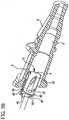
- a catheter assembly 100may include a catheter adapter 8 having a catheter 108 attached at its distal end. Wings 130 may be provided on the adapter 8. Before use and during insertion (as depicted in Fig. 1 ), a needle 30 is disposed within the catheter such that the tip or distal point 32 that extends out of the distal end of the catheter. The proximal end of the needle is attached to a needle hub 110. A finger grip 120 may be incorporated into the needle hub 110.
- Such a structure, in conjunction with the wings 130,permits the caregiver to employ various technique for catheter insertion, as discussed in U.S. Patent Application Serial No. 09/865,915, filed May 25, 2001 , incorporated herein by reference.
- a needle shield assembly 5is disposed about the needle, between the needle hub 110 and the catheter adapter 8, as shown in Fig. 1 .
- the needle shield assembly 5may be disposed completely within the catheter adapter and still practice aspects of the invention. It will be appreciated that embodiments of the invention may be implemented with either a needle shield assembly within the catheter adapter, or with a needle shield assembly disposed between the needle hub and the catheter adapter, or at other locations along the needle. Further, implementations of the invention may be employed with needles and sharps used in other devices, such as syringes and blood collection sets.
- implementations of the needle shield assembly 5are designed such that, after insertion of the over the needle catheter 108 into the patient, when the needle 30 is withdrawn, the tip 32 of the needle enters the needle shield assembly. At that point, the needle shield assembly locks onto the needle tip, preventing further displacement of the shield assembly along the needle. As such, the needle shield assembly cannot simply be slipped off the tip of the needle and removed. Additionally, when the needle shield assembly locks onto the needle, it prevents reemergence of the tip from the distal end of the needle shield assembly.
- the needle shield assemblyincludes a tilting member or canting plate 40 whose movement is constrained with respect to the needle shield assembly.
- the tilting memberis a rigid plate contained within the needle shield assembly.
- a hole 42 in the canting plateis defined by an edge 43. The needle passes through the hole 42 in the canting plate.
- the canting plateis retained in an aligned position with the needle by a retention system or canting plate retention means such that the needle passes through the canting plate without substantial interference.
- the canting plate retention meansmay include combinations of fixed structures and movable elements, springs and/or friction members that cooperate to control the position of the canting plate.
- the canting plate retention meansis triggered, causing the canting plate to come "off alignment" or be “actuated.”
- the canting plateis tilted such that it binds against the exterior of the needle, preventing relative movement of the needle to the canting plate. Since the canting plate is also constrained with respect to the needle shield assembly, the needle and its tip are also constrained with respect to the needle shield assembly - thereby locking the needle tip within the needle shield assembly.
- a feature 35may be provided on the needle to further prevent the needle shield assembly from slipping off the needle tip.
- a tether 400may also be provided to prevent the needle shield assembly from slipping off the needle tip. As discussed below, the feature and the tether can also serve to withdraw the needle shield assembly from the catheter adapter 8 as the needle hub 110 is moved proximally. Once locked in place, the shielded needle may be disposed of.
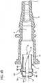
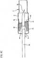
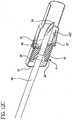
- FIGs. 2A-3Bone implementation of the invention is shown.
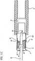
- Figs. 2A and 3Adepict the needle 30 partially withdrawn into the needle shield assembly 5, but before the needle shield assembly is actuated, or locked, onto the needle.
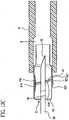
- Figs. 2B and 3Bdepict the needle shield assembly after actuation, locked onto the needle.
- the needle shield assembly 5is positioned within the catheter adapter (or simply "adapter") 8.
- the catheter 108has been omitted. It will be appreciated that the catheter is secured to the distal end of the catheter adapter and the needle extends coaxially through the catheter before use, as seen in Fig. 1 .
- the adapter 8includes an internal chamber forming a shield housing 6 in which the needle shield assembly 5 sits.
- the shield housingmay also be a structure distinct from the adapter.
- the needle shield assemblyhas a shield body 10 that includes a sidewall 9 and a distal end 11 and proximal end 12.
- the sidewallis cylindrical to fit snugly within the shield housing.
- the sidewallmay have other shapes to achieve a fit within the catheter adapter.
- the shield ends 11, 12include a distal opening 13 at the distal end and a proximal opening 14 at the proximal end.
- the needle 30has a distal needle point or tip 32 and an axis 99 and is disposed within the adapter 8, extending through the shield assembly 5 before use. Specifically, the needle passes through the shield openings 13, 14, and extends out of the distal end 7 of adapter 8, through an over-the-needle catheter 108 (not shown in Figs. 2A-3B for the sake of clarity).
- the needle diameteris sized to pass through the distal opening 13 and the proximal opening 14 of the shield body 10 without interference.
- a static feature 35is also provided on the needle 30 at a selected distance from the tip 32.
- the static feature 35is designed such that it is not capable of passage through the proximal opening 14 of shield body 10, such as disclosed in U.S. Patents 5,558,651 and 5,215,528 , both incorporated herein by reference.
- the static featurecould be an increased diameter portion on the needle 30 (that is, an enlarged dimension, such as formed by a crimp, collar, enlarged diameter sleeve or ferrule), or a roughened surface that locks onto proximal end 12 of the needle shield assembly 5.
- Other structurescan be employed to restrict movement of the needle tip out of the proximal end of the shield (such as a tether, discussed below) and still practice aspects of the invention.
- the needle shield assembly 5contains a shielding mechanism including a canting plate 40 to restrict axial movement of the needle 30 within the shield body 10.
- the canting plateincludes a hole 42 defined by an edge 43 through which the needle passes.
- the proximal end 12 of the needle shield assemblyforms a retention washer 15.
- the retention washeris attached at one end (the top as seen in Fig. 2A ) to the sidewall 9.
- a spring 45is attached at the other end of the retention washer. The spring engages canting plate, urging it to an off alignment position (that is, the actuated or locked position), as shown in Figs. 2B and 3B .
- the retention washer and springare integrally formed. It will be appreciated that these pieces could be separately formed and attached such as by welding or the like.
- the needle shield assembly 5also includes a retention arm 16.
- the retention armis a leaf spring, integrally formed with the sidewall 9 and including a lip 127 at its proximal end.
- the retention armIs biased radially outward from the needle shield assembly, as seen in Fig. 2B .
- the shield housingforces the retention arm radially inward, as seen in Fig. 2A .
- the retention armhelps maintain the canting plate 40 in a needle aligned position (that is, the unactuated or unlocked position) while the needle shield assembly is in the shield housing.
- the needle shield assembly 5includes a ledge 27 formed in the sidewall 9, remote from the retention arm 16. As shown, the ledge is formed by deforming a portion of the sidewall such that it projects radially inwardly. It will be appreciated that the ledge could be formed in other manners (such as by adhering a distinct ledge structure to the inside of the side wall, or by crimping or otherwise creating a bulge in the sidewall). Importantly, the ledge forms a stop that prevents a portion of the canting plate from moving with respect to the needle shield assembly.
- the canting plate 40in the aligned or unlocked condition, the canting plate 40 is held in place by a retention system, specifically by the cooperation of the spring 45, the lip 127 of the retention arm 16 and the ledge 27.
- the springurges the top of the canting plate in the distal direction (to the right in Fig. 2A ).
- the canting plateis prevented from rotating or displacing by the lip of the retention arm, which engages the top of the canting plate, and the ledge, which engages the bottom of the canting plate.
- the canting platethus is maintained in the aligned condition and the needle may pass freely through the hole 42 in the canting plate without substantially engaging the edge 43.
- the needle 30After insertion into a patient's vein, the needle 30 is withdrawn through the catheter 108 and the catheter adapter 8.
- the feature 35 on the needleengages the proximal end 12 of the needle shield assembly 5.
- the feature 35 on the needledoes not fit through the hole 14 in the retention washer 15. Consequently, as the caregiver pulls the needle through the catheter adapter 8, the entire needle shield assembly 5 is pulled out of the shield housing 6.
- the retention arm 16succumbs to its natural bias, moving radially outward such that the lip 127 disengages the top of the canting plate 40. Once disengaged, the canting plate is free to rotate under the urging of the spring 45.
- edge 43 of the hole 42binds onto the exterior surface of the needle 30.
- the canting plateis held in this locked condition by the cooperation of the needle, the ledge 127 and the spring 45.
- the friction on the needleurging the canting plate distally
- the ledgepreventing movement of the bottom of the canting plate
- the feature 35may be sized so that it does not fit through the hole 42 in the canting plate when the canting plate is off alignment. This will provide further resistance to re-emergence of the needle tip.
- the canting plate 40may be a rigid disk with a hole 42 through the middle of it.
- the canting plate 40is substantially circular in shape but could be any of various other shapes including square, rectangular, triangular, oval, symmetrical, asymmetrical, etc.
- the hole 42 in the center of the canting plate 40is preferably substantially the same shape as the needle 30 that goes through it.
- other hole shapescould be employed, such as rectangular, triangular or oval shape or any of a variety of other shapes, and still practice aspects of the invention.
- the canting plateneed not be flat. It can be curved or stepped or otherwise shaped for any given application.
- the hole 42 in the canting plate 40is sized to achieve adequate binding force on the needle 30 in view of the geometry of the needle and the geometry of the canting plate.
- the holeshould be at least larger than the largest diameter of the feature 35 (when the feature is an enlarged portion of the needle) and, in certain implementations, may increase to be around 100% larger than the diameter of the static feature 35 on the needle 30.
- it is preferred that the hole 42is sized between just larger than the largest diameter of the static feature 35 on the needle 30 to a hole 42 about 10-30% larger than the largest diameter of the static feature 35 on the needle 30.
- the holebe sized, in view of the geometry of the needle shield assembly, such that it engages the needle when the canting plate is tilted between 0° and 45° from perpendicular to the axis 99.
- the canting anglemay be selected based on the geometry and materials of the canting plate, the needle shield assembly and the needle and the desired binding force.
- the hole 42 in the canting plate 40is aligned concentrically to the perimeter circular shape 46 of the body of the canting plate 40.
- the plate 40could also be designed to have an eccentric center hole 42 or a hole in any location on the canting plate 40 to achieve desirable binding forces.
- the hole 42may be positioned at the exterior or outer edge 46 of the canting plate such that it breaks the outer edge 46.
- Such a structurewill create a "slotted" style of canting plate 40 in accord with certain implementations of the invention. Such may be particularly desirable to permit side loading of the needle into the plate or for use with a guide-wire.
- the plate 40has a thickness suitable for use in providing edges 43 to bind down on the needle surface 31 when the plate 40 is canted or off alignment.
- This thickness 43may vary depending on other parameters, such as the materials used, the specific geometry of the other parts of the needle shield assembly and the binding force desired.
- the canting plate 40could be entirely housed within the shield body 10 or could be partially within and partially without the shield body 10.
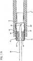
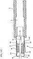
- the operation of the structureis similar to that depicted in Figs. 2A-3B .
- the canting plate or member 40 and the retention washer 15are integrally formed from the same piece of material as the shield body 10 of the needle shield assembly 5.
- the canting plateis preferably made of stainless steel, or like material.
- the material that connects the canting plate 40 to the retention washer 15serves as the spring 45, urging the canting plate into an off alignment condition.
- the canting plate 40, the spring 45 and the retention washer 15are integral to each other, but separate from the proximal end 12 of the needle shield assembly 5.
- the retention washeris attached to the shield body 10 at the proximal end such as by welding, gluing or the like. As depicted, the retention washer is attached on the inner surface of the proximal end of the shield body, but it will be appreciated that the retention washer may be attached at the exterior surface as well.
- the operation of this Implementationis otherwise similar to the prior implementations.
- this implementation of the inventionemploys a member 28, frictionally engaged to the needle 30, to retain the canting plate 40 in the aligned condition and to move the canting plate to an off-alignment condition when the needle is moved distally with respect to the needle shield assembly 5.
- the needle shield assembly 5includes a canting plate 40 and a friction member 28, such as an elastomeric washer.
- a friction member 28such as an elastomeric washer.
- the elastomeric washeris preferably designed to fit slidably within the shield body 10.
- the elastomeric washer 28has a central cavity 29 extending from the proximal end 36 to the distal end 37.
- the needle 30passes through the cavity 29 with the washer 28 engaged in a frictional fit on the needle 30.
- the friction between themcauses the elastomeric washer 28 to want to move in concert with the needle 30.
- the shield body 10 of the needle shield assembly 5includes a proximal portion 12 defining a retention washer 15.
- the shield bodyhas a distal opening 13 and the retention washer has a proximal opening 14.
- the proximal opening 14is designed to be just larger than the diameter of the shaft of the needle 30, but not large enough to permit the static feature 35 on the needle 30 to pass through.
- the retention washer 15also serves as a backstop for the elastomeric washer 28, securing it within the shield body behind the canting plate 40. As the elastomeric washer 28 is being dragged proximally by the needle 30, it will eventually bottom out on the retention washer 15 and will not be allowed further movement relative to the needle shield assembly see Fig. 8B ).
- the canting plate 40is positioned distal of the elastomeric washer 28 and is contained axially by the needle 30. Protruding inwardly from the shield body 10 is an alignment arm 19.
- the alignment arm 19defines a positive stop restricting the canting plate 40 from moving in a distal direction at that point.
- the opposing internal surface of the sidewall 9 of shield body 10is smooth and offers no resistance to the potential distal motion of the canting plate 40.
- the alignment arm 19defines a point at which the canting plate 40 will rotate.
- the alignment arm 19 and elastomeric washer 28therefore serve as the canting plate retention means or retention system.
- the elastomeric washer 28could be a variety of lengths or shapes and still practice aspects of the invention. As shown in Figs. 8A-C through 9A-C , the washer has an hourglass shape. The washer could also be a simple flat disc, donut-shaped ring or the like. The particular shape of the washer can be selected by one skilled in the art based on the particular application. While the washer depicted in Fig. 8A is not attached to the canting plate 40, it will be appreciated that the washer could be attached to the canting plate and still function.
- the cavity 48 created between the retention washer 15 and the alignment arm 19can be any length suitable for permitting the elastomeric washer 28 to reside within the shield body 10.
- the inner diameter of the elastomeric washer 28(that is, the surface which is in contact with the needle shaft 30) can be smooth or textured. It can also have an array of fins or ribs or any of an assortment of features designed to regulate the friction created against the needle 30.
- the elastomeric washer 28can be cylindrical in nature and in contact with the entire surface of the canting plate 40.
- the washer 28could be truncated on its distal end 37 and aligned specifically to have its most distal portion in contact against the canting plate 40 in a position directly opposite of the alignment arm 19 to facilitate a more undiluted force against the canting plate 40 during distal motion of the needle 30.
- the needle tip 32 of the catheter assembly 100is inserted into the patient's vein, positioning the catheter in the vein as well.
- the needle 30is then withdrawn through the catheter 108.
- the needleexerts a friction force on the elastomeric washer 28, urging it proximally as the needle is drawn through the needle shield assembly 5.
- the elastomeric washerabuts the proximal end 12 of the needle shield assembly, stopping the friction member as the needle slides through the central cavity 29.
- the feature 35 on the needlecontacts the proximal end 12 of the needle shield assembly (for example, the retention washer 15)
- the featureengages the proximal end, preventing further proximal movement of the needle with respect to the needle shield assembly.
- the needle shield assembly 5is pulled out of the shield housing 6, as shown in Fig. 8B (referred to as "bottoming out").
- the friction member 28is urged by friction with the needle 30 in the distal direction.
- the canting plateis also urged distally.
- the alignment arm 19,which abuts a portion of the canting plate, restrains that portion, causing the canting plate to tilt to an off alignment, or actuated, condition, as seen in Fig. 8C .
- the feature 35engages the friction member, causing it to move distally and engage the canting plate.
- Figs. 8C and 9Cthe feature 35 engages the friction member, causing it to move distally and engage the canting plate.
- the friction membercan be more tightly fit on the needle such that it moves with the needle whether the feature engages the friction member or not.
- the edge 43 of the hole 42 in the canting platethen binds on the exterior of the needle, preventing further displacement of the needle 30 with respect to the canting plate 40 (and thus the needle shield assembly 5).
- the shield body 10 of the needle shield assemblyis long enough to ensure that the tip 32 of the needle 30 does not reemerge from the distal end 11 of the needle shield assembly when the canting plate is actuated.
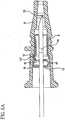
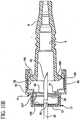
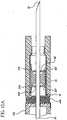
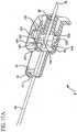
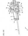
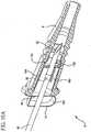
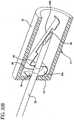
- FIGs. 10A-BA further implementation of an aspect of the instant invention is illustrated in Figs. 10A-B .
- An interlock 50is included to lock the catheter adapter 8 to the shield body 10 until the needle 30 is in a shielded position.
- the static feature 35 on the needleis employed to activate an adapter release 55, thereby disengaging the needle shield assembly 5 from the catheter adapter.
- the canting plate 40is maintained in the aligned position by the elastomeric washer 28, the ledge 27 and an alignment arm 227.
- the ledgeis fixedly attached to the needle shield assembly 5.
- the alignment armmay be in the form of a leaf spring attached to the adapter release 55.
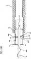
- the needle shield assembly 5includes locking flanges 158 in the form of leaf springs attached near the distal end of the needle shield assembly and extending proximally. In their original, undeformed condition, the flanges extend relatively straight (that is, parallel to the axis of the needle shield assembly 5) ( Fig. 10C ).
- the locking flanges 158engage the collar 180 of the adapter 8, preventing the collar (and thus the adapter) from coming out of the needle shield assembly. See Fig. 10A .
- the release pin 56prevents the locking flanges 158 from displacing radially inward.
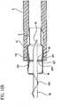
- the release pinAs the release pin is moved to the proximal position 58, it disengages the flanges 158 such that they are free to flex radially outwardly.
- the collarforces the locking flanges radially outwardly, as seen in Fig.
- the needle shield assembly 5may slide off the adapter 8.
- the distal opening 13 of the needle shield assembly 5is open, even after the needle tip 32 is shielded.
- the length of the needle shield clips or other such mechanismsfurther may be employed to create a transverse barrier to further prevent reemergence.
- static feature 35is employed to resist slipping the needle shield assembly 5 off the tip 32 of the needle 30. It will be appreciated that other structures, such as a tether, may be employed to prevent such removal.
- the needle tip 32 of the catheter assembly 100is inserted into the patient's vein, positioning the catheter 108 in the vein as well.
- the needle 30is withdrawn through the catheter 108 and the catheter adapter 8.
- the needleexerts a friction force on the washer 28.
- the washeris retained in position by the proximal wall 155 of the adapter release 55.
- the alignment arm 227deflects over the canting plate 40.
- the alignment armhas an angled shape such that, when it is moved distally, it then tilts the canting plate to an off alignment condition.
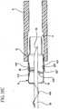
- the adapter releasecontinues to move within the shield body until the proximal wall 155 contacts the proximal end 12 of the shield body. At that point, further distal movement of the needle with respect to the needle shield assembly is prevented (see Fig. 10B ).
- the release pin 56is withdrawn from engagement with the locking flange 158.
- the locking flangeis then free to displace radially outwardly as the collar 180 forces its way out of the needle shield assembly. As such, the needle shield assembly 5 can be separated from the adapter 8.
- this implementation of the inventionis similar in operation to that depicted in Figs. 8A-C and 9A-C .
- a spring arm 427is compressed radially inward before actuation to assist in maintaining the canting plate 40 in alignment before use. See Fig. 11A .
- the canting plate 40is maintained in alignment before actuation by the cooperation of elastomeric washer 28 with retention arm 16 and ledge 27.
- the needle 30can be moved proximally and distally within the assembly. In use, the needle is withdrawn until the feature 35 contacts the retention washer 15.
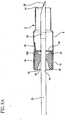
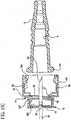
- Figs. 13A through 13Cdepict another implementation of an aspect of the invention including a single canting plate 40 which binds onto the needle 30, thereby preventing movement of the needle with respect to the needle shield assembly 5 in both the proximal and distal directions.
- the needle shield assemblyincludes a proximal retention arm 216 and a distal retention arm 116 integrally formed with the shield body 10.
- a proximal ledge 227 and a distal ledge 327are mounted on spring arm 427.
- the shield housing 6 of the adapter 8compresses or flexes the spring arm radially inwardly, and into engagement with the canting plate 40.
- An elastomeric washer 228is attached to the canting plate and is frictionally engaged to the needle.
- a feature 35Is permanently attached to the needle.
- the retention washer 15 at the distal end of the needle shield assemblyincludes an opening 14 that is sized to permit movement of the needle therethrough but to prevent passage of the feature 35.
- the userinserts the needle tip 32 of the over-the-needle catheter assembly 10 into the patient's vein.
- the usergrasps the needle hub 110, pulling the needle hub away from the catheter adapter 8 , thereby causing the needle 30 to be withdrawn through the catheter adapter 8 and the needle shield assembly 5.
- the needlecontinues to be withdrawn through the needle shield assembly until the feature 35 contacts the retention washer 15. Further displacement of the needle causes the needle shield assembly 5 to be withdrawn from the shield housing 6 in the adapter 8.
- Fig. 13BAs the needle shield assembly is fully withdrawn from the shield housing in the catheter adapter, the spring arm 427 is free to rotate radially outward from the needle shield assembly.
- the proximal ledge 227 and the distal ledge 327disengage the canting plate 40. See Fig. 13C . Consequently, the canting plate can be rotated. The upper edge of the canting plate is prevented from moving either distally or proximally by the retention arms 116, 216.
- the needle shield assembly 5includes a distal retention arm 116 and a proximal retention arm 216 which are preferably integrally formed with the shield body 10. As depicted, the retention arms are deformed radially inward, such as by bending. A distal canting plate 140 and a proximal canting plate 240 are disposed within the shield body. The canting plates are maintained in an aligned condition by the cooperation of the retention arms with distal ledge 327 and proximal ledge 227 and the elastomeric washer 28, discussed below. The ledges 227, 327 are mounted to a spring arm 527.
- the spring arm 527is biased radially inward such that the ledges 227, 327 engage the canting plates 140, 240.
- a friction membersuch as hourglass-shaped washer 28, is disposed between the distal canting plate 40 and the proximal canting plate 240 within the shield body 10.
- the elastomeric washer 28is frictionally engaged to the needle.
- the elastomeric washer 28may be compressed when disposed between the two canting plates.as depicted in Fig. 14A . In such case, the washer is exerting a continuous biasing force on the canting plates which is resisted by the needle shield assembly.
- needle tip 32 of the over-the-needle catheter assembly 100is inserted into the patient's vein.
- the needle 30is withdrawn through the catheter 108 such that the needle passes through the needle shield assembly 5.
- the distal canting plate 140is maintained in alignment with the needle by the cooperation of the elastomeric washer 28, the distal retention arm 116 and the distal ledge 327.
- the proximal canting plate 240is maintained in alignment by the cooperation of the elastomeric washer, the proximal retention arms 216 and the proximal ledge 227 despite urging of the washer 28 (which is seeking to follow the needle and, thus, being moved against the canting plates).
- the needlepasses freely through the openings in the canting plates.
- the feature 35engages the retention washer 15, causing the needle shield assembly 5 to be pulled out of the shield housing 6 in the adapter 8. See Fig. 14B .
- the spring arm 527is free to expand radially outward from the shield body, such that the proximal ledge 227 disengages the proximal canting plate 240 and the distal ledge 327 disengages the distal canting plate 140. This disengagement permits the canting plate to rotate. If the washer had been compressed, it will be free to expand, thereby causing immediate tilting of the canting plates.
- the needle 30will urge the washer 28 distally which, in turn, will cause the proximal canting plate 240 to rotate, as seen in Fig. 14B .
- the washer 28will move distally, urging the distal canting plate 140 to move distally.
- the distal retention arm 116will prevent the distal canting plate 140 from translating distally within the needle shield body 10, resulting in tilting of the distal canting plate and binding on the needle. See Fig. 14C .
- FIGs. 15A through Can implementation of the invention is depicted which employs a tether 400 to extract the needle shield assembly 5 from the shield housing 6 of the catheter adapter 8 .
- the tetheris attached to the needle hub 110 and to the proximal end 12 of the needle shield assembly.
- the tetheris attached to the retention washer 15. Because the tether extracts the needle shield assembly from the catheter adapter, no feature 35 on the needle is required.
- the needle tip 32is inserted into the patient's vein, delivering the tip of the catheter 108 to the vein as well. The caregiver then withdraws the needle hub 110 while holding the catheter adapter 8 in place. See Fig. 15B .
- the tether 400extends until it is at its full length.
- the needle shield assembly 5is pulled out of the shield housing 6 in the catheter adapter 8. See Fig. 15B .
- the operation of this implementationis otherwise similar to the implementation depicted and described in connection with Figs. 14A through 14C .
- a tether 400is used to extract the needle shield assembly 5 from the shield housing 6 in the catheter adapter 8. Consequently, no feature 35 is required on the needle.
- a single canting plate 40binds onto the needle 30 after actuation, thereby preventing movement of the needle with respect to the needle shield assembly in both the proximal and distal directions.
- the needle shield assembly 5includes a proximal retention arm 216 and a distal retention arm 116 integrally formed with the shield body 10.
- a proximal ledge 227 and a distal ledge 327are mounted on spring arm 427.
- the shield housing 6 of the adapter 8compresses or flexes the spring arm radially inwardly, and into engagement with the canting plate 40.
- An elastomeric washer 228is attached to the canting plate and is frictionally engaged to the needle.
- a feature 35is permanently attached to the needle.
- the userinserts the needle tip 32 of the over-the-needle catheter 100 into the patient's vein, thereby positioning the tip of the catheter 108 in the vein as well.
- the usergrasps the needle hub 110, pulling the needle hub away from the catheter adapter 8, thereby causing the needle 30to be withdrawn through the catheter adapter 8 and the needle shield assembly 5.
- the tether 400is extended to its full length, further proximal movement of the needle hub begins withdrawing the needle shield assembly from the catheter adapter. See Fig. 16B .
- the spring arm 427is free to rotate radially outward from the needle shield assembly.
- proximal ledge 227 and the distal ledge 327disengage the canting plate 40. See Fig. 16C . Consequently, the canting plate can be rotated. The upper edge of the canting plate is prevented from moving either distally or proximally by the retention arms 116, 216. Re-emergence of the needle is prevented by a binding force from the canting plate on the exterior wall of the needle 30, as discussed in connection with Figs. 13A-C . See Fig. 16D .
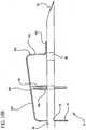
- a clip 130is disposed within the housing of the needle shield assembly 5.
- the clipis a substantially v-shaped member with a first leg 131 securely mounted to the housing.
- the second leg 132is mounted to the first leg via a flexural hinge 133.
- Slide tabs 134are formed in the second leg to reduce the interference between the needle 30 and the second leg during actuation and slidingly engage the needle 30.
- the clip 130is compressed and maintained in the compressed condition by the presence of the needle within the needle shield 5 at a point aligned with the clip.
- a trap arm 730is attached to the second leg 132 and engages a catheter adapter (not shown), preventing its removal from the needle shield assembly. As the needle is withdrawn, it ceases to engage the second leg such that the flexural hinge 133 springs open. See Figs. 17C and 17D . The trap arm then moves out of engagement with the catheter adapter so that it can be removed from the needle shield assembly.
- a guide plate 140is attached to the second leg 132 of the clip 130.
- the guide plateincludes a guide slot 141.
- a canting pin 142is attached to the canting plate 40.
- the canting pinmay be integrally formed with the canting plate.
- the canting pinis disposed within the guide slot 141.
- the movement of the guide plateresults in the pin 142 being displaced in a distal direction.
- the bottom edge of the canting plateis prevented from translating proximally or distally because it is retained within a groove 740 in the needle shield assembly housing.
- the pin 142is moved distally, the canting plate is rotated into binding engagement with the needle.
- the engagement of the canting plateprevents the needle from re-emerging out of the needle shield assembly.
- the retention washer 15prevents movement of the feature 35 (and therefore movement of the needle tip 32) out of the proximal end of the needle shield assembly. It will be appreciated that the feature could be removed and a tether provided to prevent the needle shield assembly from sliding off the tip of the needle.
- a retention washer 15integrally formed with an actuator arm 150.
- An opening 14is disposed in the retention washer.
- a lipmay be formed about the opening 14 to ease the passage of the needle and to ensure relatively perpendicular alignment between the retention washer and the needle.
- the actuator armincludes a front wall 151 and a slide plate 152.
- An aperture 153is disposed in the front wall but may be eliminated in certain implementations.
- the canting plate 40is maintained in position about the needle by a pair of u-shaped sleeves 154. The sleeves are in a relatively close fit with the canting plate 40 but not so close that the canting plate cannot slide within the sleeves. Compare Fig. 18B and 18D .
- the u-shaped sleevesare themselves attached to the arm 150.
- An aperture 155is disposed in the arm directly above the canting plate.
- the retention plate 15 and the arm 150are flexed away from each other (that is, biased open) and maintained in this flexed condition by the presence of the needle 30 in the opening 14 of the retention washer, and the engagement of the needle with the plate 152.
- the needle shield assembly 5is moved toward the needle tip 32 (or, alternatively, the needle 30 is withdrawn through the needle shield assembly).
- the tip 32 of the needlepasses beyond the slide plate 152 such that the arm 150 and retention plate 15 can return to their unbiased condition, rotating toward each other, as seen in Figs. 18C and 18D .
- the u-shaped members 154are displaced with respect to the retention washer 15 (specifically, the u-shaped members are rotated with respect to the retention plate). Compare Fig. 18B with Fig. 18D . As such, the canting plate 40 is also displaced with respect to the retention washer (and thus the needle). Effectively, the canting plate is tilted with respect to the needle and thereby engages the exterior of the needle. In the actuated condition, the top of the canting plate protrudes through the aperture 155 in the arm 150. It will be appreciated that the arm 150 could be designed such that such an aperture 155 would not be required but this would result in a larger needle shield assembly 5.
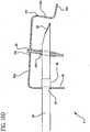
- FIGs. 19A and 19Ban implementation is depicted that includes a mechanism for engaging a catheter adapter 8 until the needle tip 32 has been withdrawn into the needle shield assembly 5, somewhat similar to the implementation depicted in Figs. 4A-B .
- the needle shield assemblyincludes two engagement arms 190 (preferably in the form of leaf springs integrally formed with the shield body 10) that are biased radially outwardly from the body of the needle shield assembly. Hooks 191 are attached to the distal end of the engagement arms 190. In the unactuated condition, the needle 30 is positioned between the hooks, thereby urging the hooks and the engagement arms radially outward. The hooks therefore are disposed within an annular groove 192 in the catheter adapter 8.
- the catheter adaptermay not be displaced off of the needle shield assembly.
- the engagement armsflex radially inward to their unstressed condition as seen in Fig. 19B .
- the hooks 191disengage the annular groove 192. Consequently, the needle shield assembly 5 may now be removed from the catheter adapter 8.
- the needle shield assembly 5also includes a retention washer 15 integrally formed with a canting plate 40 and connected by a flexural hinge member 193.
- the hinge memberis a spring which urges the canting plate 40 into a canted condition.
- the canting plateis free to succumb to the bias of the flexural hinge 193 and thus engage the exterior of the needle 30 (see Fig. 19B ).
- a retention washer 15integrally formed with a flexural hinge 193 which in turn integrally formed with a canting plate 40 which is in turn integrally formed with an actuation arm 150.
- the retention washeris attached to the proximal end 12 of a shield body 10.
- the canting plateIn the unactuated condition, the canting plate is maintained in alignment with the needle 30 by the cooperation of the force exerted by the flexural hinge 193 and the restraint exerted by actuation arm 150.
- the flexural hinge 193acts as a spring urging the canting plate into a canted or engaging condition. This movement of the canting plate is prevented by the actuation arm which itself is engaged to the needle.
- a cutout 159may be provided on the actuation arm to permit movement of the actuation arm after passage of the needle tip without interference from the needle.
- certain implementations of the inventionemploy a feature 35 on the needle 30 to limit motion of the needle shield assembly 5 with respect to the tip 32 of the needle.
- Other implementationsemploy a tether 400 to limit motion of the needle tip with respect to the needle shield assembly.
- the featuremay be replaced with a tether (or the tether replaced with a feature) and still practice the invention.
- the friction memberis referred to, in certain implementations as an elastomeric washer. It will be appreciated that the friction member may be made of elastomers, or other materials having different properties and various shapes and still practice aspects of the invention.
Landscapes
- Health & Medical Sciences (AREA)
- Life Sciences & Earth Sciences (AREA)
- Engineering & Computer Science (AREA)
- Anesthesiology (AREA)
- General Health & Medical Sciences (AREA)
- Biomedical Technology (AREA)
- Heart & Thoracic Surgery (AREA)
- Hematology (AREA)
- Veterinary Medicine (AREA)
- Animal Behavior & Ethology (AREA)
- Public Health (AREA)
- Biophysics (AREA)
- Pulmonology (AREA)
- Vascular Medicine (AREA)
- Environmental & Geological Engineering (AREA)
- Infusion, Injection, And Reservoir Apparatuses (AREA)
- Media Introduction/Drainage Providing Device (AREA)
Abstract
Description
- The subject invention relates to a needle shield assembly constructed to safely shield the sharp distal tip of a needle, and restrict distal movement of the needle tip via a tilting or "canting" plate after the tip is shielded.
- Intravenous (IV) catheters are used for infusing fluid, such as normal saline solution, various medicaments and total parenteral nutrition, into a patient or withdrawing blood from a patient. Peripheral IV catheters tend to be relatively short, and are on the order of about one and one-half inches in length. A common type of IV catheter is an over the needle peripheral IV catheter. As its name implies, an over the needle catheter is mounted over an introducer needle having a sharp distal tip. The catheter and the introducer needle are assembled so that the distal tip of the introducer needle extends beyond the distal tip of the catheter with the bevel of the needle facing up away from the patient's skin.
- The catheter and introducer needle assembly are inserted at a shallow angle through the patient's skin into a peripheral blood vessel (i.e., a smaller blood vessel that is not connected directly to the heart but is one of the branches of the central blood vessels that is directly connected to the heart). In order to verify proper placement of the assembly in the blood vessel, the clinician confirms that there is flashback of blood in the needle and in a flashback chamber located at the proximal end of the needle. Typically, the flashback chamber is formed as part of the needle hub. Once proper placement is confirmed, the clinician applies pressure to the blood vessel by pressing down on the patient's skin near the distal tip of the introducer needle and the catheter. This finger pressure occludes further blood flow through the introducer needle. The clinician withdraws the introducer needle, leaving the catheter in place, and attaches a fluid-handling device to the catheter hub. Once the introducer needle is withdrawn from the catheter, it is deemed a "blood contaminated sharp" and must be properly handled.
- In recent years, there has been great concern over the contamination of clinicians with a patient's blood and a recognition that "blood contaminated sharps" must be immediately disposed. This concern has arisen, in part, to reduce the risks associated with spreading diseases that can be transmitted by the exchange of body fluids from an infected person to another person. Thus, it is desirable to avoid contact with the body fluid of an infected person. Various needle shields have been developed. Generally, such needle shields work for their intended purpose but could be improved. For example, some needle shields are bulky, difficult to use or require special features or techniques to be operative.
US-A-6,117,108 describes a safety IV catheter corresponding to the first part of claim 1. This catheter comprises a needle hub connected to a needle and a catheter hub connected to a catheter. The catheter hub forms a housing that includes a needle shield assembly. The needle shield assembly is an elastic clamp having openings through which the needle extends. If the needle is proximally withdrawn from the catheter, the needle shield assembly remains within the catheter hub and when the needle tip passes the distal end of the needle shield assembly, the elastic needle shield assembly is partially released so that the portion thereof covers the needle tip, whereas a remaining portion clamps on the needle.- It is an object of the invention to provide an apparatus for shielding a needle that has a new releasing mechanism.
- The apparatus of the present invention is defined by claim 1.
- In accord with one aspect of the invention, an over the needle catheter assembly includes a catheter adapter and a needle. The needle has a diameter and a distal tip, slidingly disposed within the catheter adapter. A needle shield assembly is slidably mounted on the needle. The needle shield assembly has an open distal end and an open proximal end though which the needle passes. A rigid plate, referred to as a "canting plate," is disposed within the needle shield assembly and has an unactivated first position and an activated second position. In the second position, the canting plate restricts needle movement. Means for retaining the canting plate are provided. The canting plate retention means is in communication with the canting plate and responsive to proximal movement of the needle, whereby, when the needle tip is housed within the needle shield assembly, the canting plate retention means is actuated, causing distal movement of the needle to urge the canting plate from the unactivated first position to the activated second position.
- In accord with certain implementations of this aspect of the invention, the canting plate retention means comprises a spring, a retention arm, and a retention washer. The spring may be selected from the group consisting of a coil spring, a wave washer, and a leaf spring or the like. The needle shield assembly may have a plurality of canting plates responsive to the canting plate retention means. The canting plate retention means may include a canting plate retention arm and a retention washer attached to the canting plate and having a built-in spring. The retention washer may be housed entirely within the shield. The canting plate retention means may include an elastomeric washer and an alignment arm. The elastomeric washer may have a truncated distal end. The catheter adapter and the shield may be held together by an interlock. A static feature may be provided on the needle, wherein said interlock is released prior to or substantially simultaneous with the static feature on the needle contacting the shield proximal end. The length between the needle tip and the static feature is such that when said static feature contacts the shield proximal end, the needle tip is housed within the shield. The canting plate may contain a hole for passage of the needle and be located distally of the proximal end of the shield. The canting plate may be returned to an unactivated position when the needle is no longer urged in a distal direction.
- In accord with another aspect of the invention, the over the needle catheter, discussed above, may be used in accord with a method including pulling the needle proximally until the static feature contacts the needle shield's proximal end, confirming that the needle tip is within the shield, and urging the needle distally to cause the canting plate to lock to prevent further distal movement.
- In accord with one aspect of the invention, an apparatus is provided for shielding a needle including a housing. A needle shield assembly is movable from an unlocked position within the housing and a locked position outside the housing. The needle shield assembly includes a shield body having a sidewall, a proximal end and a distal end. A canting member is disposed within the shield body for movement from an aligned condition to an off-alignment condition. A spring is operably engaged to the shield body and the canting member, urging the canting member to the off-alignment condition. A retention arm is engaged to the shield body and is displaceable from an engaged position to a disengaged position. When the needle shield assembly is within the housing, the housing displaces the retention arm to the engaged position in which the retention arm engages the canting member and maintains the canting member in the aligned condition. When the needle shield is outside the housing, the retention arm moves to the disengaged position in which the retention arm disengages the canting member, and the canting member is displaced to the off-alignment condition by the spring.
- Certain implementations of this aspect of the invention provide the canting member is a canting plate. The spring may be a leaf spring integrally formed with the canting member. The shield body, canting plate and spring may be integrally formed. The shield body may include a retention washer disposed at the proximal end of the shield body, and the retention washer defines an opening through which the needle passes.
- The apparatus discussed above may be used with a needle including a feature having a diameter greater than the body of the needle. The opening in the retention washer is sized to permit the needle body to pass but to prevent the feature from passing therethrough. The shield body may include a retention arm that, when the needle shield assembly is within the housing, is biased radially inward to engage the canting member and, when the needle shield assembly is outside the housing, moves radially outward to disengage the canting member. The shield body may include a ledge, disposed opposite the retention arm, and abutting the canting member. The ledge may be integrally formed with the sidewall.
- In accord with another aspect of the invention, a needle shield assembly includes a shield body having a sidewall, a proximal end and a distal end. A member, such as an elastomeric washer, is disposed within the shield body and has a central cavity. The cavity is sized to frictionally engage the needle. A canting member is disposed within the shield body and movable between an aligned condition and an off-alignment condition. The member is selectively engaged to the canting member such that, as the needle is moved in a proximal direction with respect to the shield body, the needle displaces the member which, in turn, displaces the canting member to the off-alignment condition.
- Certain implementations of this aspect of the invention provide that the member is an elastomeric member and the canting member is a canting plate. Means may be provided for retaining the canting member in the aligned condition. An alignment arm is mounted to the shield body and abuts the canting member. The member is an elastomeric washer abutting the canting member and the proximal end of the shield body. The member is attached permanently and directly to the canting member. A ledge may be fixedly attached to the shield body, disposed distal to the canting member and abutting the canting member. An interlocking flange may be mounted at the distal end of the shield body and an adapter release may be slidably disposed within the shield body. The adapter release includes a release pin that engages the interlocking flange when the canting plate is in the aligned condition and biases the interlocking flange into engagement with a catheter adapter.
- The preferred embodiments are illustrated in the drawings in which like reference numerals refer to like elements and in which:
Fig. 1 is a perspective view of an over the needle catheter assembly for use in accord with an aspect of the invention;Fig. 2A is a cross-sectional view of one embodiment of the invention shown in an unactuated condition, where the needle has been partly withdrawn through the catheter but the sharp distal tip of the introducer needle has yet to be withdrawn into the needle shield;Fig. 2B is a cross-sectional view of the embodiment of the needle shield inFig. 2A in an actuated condition where the sharp distal tip of the introducer needle has been withdrawn proximally into the needle shield assembly;Fig. 3A is a perspective view of the needle shield as depicted inFig. 2A in partial cross section;Fig. 3B is a perspective view of the needle shield as depicted inFig. 2B in partial cross section;Fig. 4A is a cross-sectional view of another embodiment of the invention, with the canting plate and spring integral to the shield, shown in an unactuated condition, where the needle has been partly withdrawn through the catheter but the sharp distal tip of the introducer needle has yet to be withdrawn into the needle shield;Fig. 4B is a cross-sectional view of the embodiment inFig. 4A in an actuated condition where the sharp distal tip of the introducer needle has been withdrawn proximally into the needle shield assembly;Fig. 5A is a cross-sectional perspective view of the needle shield ofFig. 4A ;Fig. 5B is a cross-sectional perspective view of the needle shield assembly depicted inFig. 4B ;Fig. 6A is a cross-sectional view of another embodiment of the invention, with the canting plate, retention washer and spring integrally formed, shown in an unactuated condition, where the needle has been partly withdrawn through the catheter but the sharp distal tip of the introducer needle has yet to be withdrawn into the needle shield;Fig. 6B is a cross-sectional view of the embodiment inFig. 6A in an actuated condition where the sharp distal tip of the introducer needle has been withdrawn proximally into the needle shield assembly;Fig. 7A is a cross-sectional perspective view of the needle shield ofFig. 6A ;Fig. 7B is a perspective view of the needle shield assembly depicted inFig. 6B in partial cross section;Fig. 8A is a cross-sectional view of an embodiment not belonging to the invention in which the canting plate is actuated by friction on the needle, shown in an unactuated condition, where the needle has been partly withdrawn through the catheter but the sharp distal tip of the introducer needle has yet to be withdrawn into the needle shield;Fig. 8B is a cross-sectional view of the embodiment inFig. 8A where the sharp distal tip of the introducer needle has been withdrawn proximally into the needle shield assembly;Fig. 8C is a cross-sectional view of the embodiment inFig. 8A where the sharp distal tip of the introducer needle is being urged distally and the canting plate is tilted to an actuated condition;Fig. 9A is a perspective view of the needle shield assembly depicted inFig. 8A in partial cross section;Fig. 9B is a perspective view of the needle shield assembly depicted inFig. 8B in partial cross section;Fig. 9C is a perspective view of the needle shield assembly depicted inFig. 8C in partial cross section;Fig. 10A is a cross-sectional view of another embodiment not belonging to the invention in which the canting plate is actuated by friction on the needle and including an interlock, shown in an unactuated condition, where the needle has been partly withdrawn through the catheter but the sharp distal tip of the introducer needle has yet to be withdrawn into the needle shield;Fig. 10B is a cross-sectional view of the embodiment inFig. 10A where the sharp distal tip of the introducer needle has been withdrawn proximally into the needle shield assembly and the catheter adapter has been partially removed;Fig. 10C is a cross sectional view of the embodiment ofFig. 10A where the sharp distal tip of the introducer needle has been withdrawn proximally into the needle shield assembly and the catheter adapter has been completely removed;Fig. 11A is a cross-sectional view of another embodiment of the invention in which the canting plate is actuated by friction on the needle, shown in an unactuated condition, where the needle has been partly withdrawn through the catheter but the sharp distal tip of the introducer needle has yet to be withdrawn into the shield;Fig. 11 B is a cross-sectional view of the embodiment inFig. 11A where the sharp distal tip of the introducer needle has been withdrawn proximally into the needle shield;Fig. 11C is a cross-sectional view of the embodiment ofFig. 11A where the sharp distal tip of the introducer needle is being urged distally and the canting plate is tilted to an actuated condition;Fig. 12A is a perspective view of a needle shield assembly depicted inFig. 11A in partial cross-section;Fig. 12B is a perspective view of the needle shield assembly depicted inFig. 11B in partial cross-section;Fig. 12C is a perspective view of the needle shield assembly depicted inFig. 11C in partial cross-section;Fig. 13A is a cross-sectional view of another embodiment of the invention in which the canting plate is actuated by friction on the needle shown in an unactuated condition where the needle has been partly withdrawn through the catheter but the sharp distal tip of the introducer needle has yet to be withdrawn into the needle shield;Fig. 13B is a cross-sectional view of the embodiment inFig. 13A where the sharp distal tip of the introducer needle has been withdrawn proximally into the needle shield assembly;Fig. 13C is a cross-sectional view of the embodiment inFig. 13A where the sharp distal tip of the introducer needle is being urged distally and the canting plate is tilted in an actuated condition;Fig. 14A is a cross-sectional view of another embodiment of the invention in which the canting plate is actuated by friction on the needle, shown in an unactuated condition, where the needle has been partly withdrawn through the catheter but the sharp distal tip of the introducer needle has yet to be withdrawn into the shield;Fig. 14B is a cross-sectional view of the embodiment inFig. 14A where the sharp distal tip of the introducer needle has been withdrawn proximally into the needle shield assembly;Fig. 14C is a cross-sectional view of the embodiment inFig. 14A where the sharp distal tip of the introducer needle is being urged distally and the canting plate is tilted to an actuated condition;Fig. 15A is a cross-sectional view of another embodiment of the invention in which the canting plate is actuated by friction on the needle, and including a tether to connect a needle hub to the needle shield assembly, shown in an unactuated condition, where the needle has been partly withdrawn through the catheter but the sharp distal tip of the introducer needle has yet to be withdrawn completely into the needle shield;Fig. 15B is a cross-sectional view of the embodiment ofFig. 15A in which the sharp distal tip of the introducer needle has been withdrawn proximally into the needle shield assembly;Fig. 15C is a cross-sectional view of the embodiment ofFig. 15B in which the sharp distal tip of the introducer needle is being urged distally and the canting plate is tilted to an actuated condition;Fig. 16A is a perspective view of another embodiment of the invention in which the canting plate is actuated by friction on the needle, shown in an unactuated condition;Fig. 16B is a cross-sectional view of the embodiment inFig. 17A where the sharp distal tip of the introducer needle has been withdrawn proximally into the needle shield assembly;Fig. 16C is a cross-sectional view of the embodiment ofFig. 17A in which the sharp distal tip of the introducer needle has been withdrawn proximally into the needle shield assembly and the canting plate has been urged to engage the needle to prevent further proximal movement; andFig. 16D is a cross-sectional view of the embodiment ofFig. 17A in which the sharp distal tip of the introducer needle is being urged distally and the canting plate is tilted to an actuated condition.Fig. 17A is a perspective view in partial cross-section of another embodiment not belonging to the invention in which the canting plate is actuated by an angled guide on a clip, shown in an unactuated position.Fig. 17B is a rear perspective view of the embodiments depicted inFig. 17A ;Fig. 17C is a front cross-sectional view of the embodiment inFig. 17A shown in an actuated condition;Fig. 17D is a rear perspective view of the embodiment depicted inFig. 17A in an actuated condition;Fig. 18A is a front perspective view of another embodiment not belonging to the invention in which the canting plate is actuated by an integral spring member shown in an unactuated condition;Fig. 18B is a side cross-sectional view of the embodiment shown inFig. 18A in an unactuated condition;Fig. 18C is a front perspective view of the embodiment shown inFig. 18A shown in an actuated condition;Fig. 18D is a cut-away side view of the embodiment shown inFig. 18A in an actuated condition;Fig. 19A is a front perspective view of another embodiment not belonging to the invention in which the needle shield assembly is engaged with a catheter hub until the needle tip is withdrawn into the needle shield assembly, shown in an unactuated condition;Fig. 19B is a front perspective view of the embodiment shown inFig. 19A in an actuated condition;Fig. 20A is a front perspective view in partial cut-away of another embodiment not belonging to the invention in which the canting plate is integrally formed with a retention washer and a tip trigger, shown in an unactuated condition; andFig. 20B is a front perspective view of the embodiment shown inFig. 20A in an actuated condition.- As used herein, the term "proximal" refers to a location on the catheter and needle shield assembly of this invention closest to the clinician using the device and farthest from the patient in connection with whom the device is used when the device is used in its normal operation. Conversely, the term "distal" refers to a location on the catheter and needle shield assembly of this invention farthest from the clinician using the device and closest to the patient in connection with whom the device is used when the device is used in its normal operation.
- A
catheter assembly 100 may include acatheter adapter 8 having acatheter 108 attached at its distal end.Wings 130 may be provided on theadapter 8. Before use and during insertion (as depicted inFig. 1 ), aneedle 30 is disposed within the catheter such that the tip ordistal point 32 that extends out of the distal end of the catheter. The proximal end of the needle is attached to aneedle hub 110. Afinger grip 120 may be incorporated into theneedle hub 110. Such a structure, in conjunction with thewings 130, permits the caregiver to employ various technique for catheter insertion, as discussed inU.S. Patent Application Serial No. 09/865,915, filed May 25, 2001 - A
needle shield assembly 5 is disposed about the needle, between theneedle hub 110 and thecatheter adapter 8, as shown inFig. 1 . Alternatively, as shown in,inter alia,Figs. 2A and2B , theneedle shield assembly 5 may be disposed completely within the catheter adapter and still practice aspects of the invention. It will be appreciated that embodiments of the invention may be implemented with either a needle shield assembly within the catheter adapter, or with a needle shield assembly disposed between the needle hub and the catheter adapter, or at other locations along the needle. Further, implementations of the invention may be employed with needles and sharps used in other devices, such as syringes and blood collection sets. - As discussed more fully below, implementations of the
needle shield assembly 5 are designed such that, after insertion of the over theneedle catheter 108 into the patient, when theneedle 30 is withdrawn, thetip 32 of the needle enters the needle shield assembly. At that point, the needle shield assembly locks onto the needle tip, preventing further displacement of the shield assembly along the needle. As such, the needle shield assembly cannot simply be slipped off the tip of the needle and removed. Additionally, when the needle shield assembly locks onto the needle, it prevents reemergence of the tip from the distal end of the needle shield assembly. - To achieve this locking between the
needle shield assembly 5 and theneedle 30, the needle shield assembly includes a tilting member or cantingplate 40 whose movement is constrained with respect to the needle shield assembly. Preferably, the tilting member is a rigid plate contained within the needle shield assembly. Ahole 42 in the canting plate is defined by anedge 43. The needle passes through thehole 42 in the canting plate. In the unlocked condition (seen, e.g., inFig. 2A ), the canting plate is retained in an aligned position with the needle by a retention system or canting plate retention means such that the needle passes through the canting plate without substantial interference. As discussed more fully below, the canting plate retention means may include combinations of fixed structures and movable elements, springs and/or friction members that cooperate to control the position of the canting plate. As thetip 32 of the needle is withdrawn into the needle shield assembly, the canting plate retention means is triggered, causing the canting plate to come "off alignment" or be "actuated." The canting plate is tilted such that it binds against the exterior of the needle, preventing relative movement of the needle to the canting plate. Since the canting plate is also constrained with respect to the needle shield assembly, the needle and its tip are also constrained with respect to the needle shield assembly - thereby locking the needle tip within the needle shield assembly. Afeature 35 may be provided on the needle to further prevent the needle shield assembly from slipping off the needle tip. Atether 400 may also be provided to prevent the needle shield assembly from slipping off the needle tip. As discussed below, the feature and the tether can also serve to withdraw the needle shield assembly from thecatheter adapter 8 as theneedle hub 110 is moved proximally. Once locked in place, the shielded needle may be disposed of. - Referring now to
Figs. 2A-3B , one implementation of the invention is shown.Figs. 2A and3A depict theneedle 30 partially withdrawn into theneedle shield assembly 5, but before the needle shield assembly is actuated, or locked, onto the needle.Figs. 2B and3B depict the needle shield assembly after actuation, locked onto the needle. In the unlocked or unactuated condition (Figs. 2A and3A ), theneedle shield assembly 5 is positioned within the catheter adapter (or simply "adapter")8. For the sake of clarity, thecatheter 108 has been omitted. It will be appreciated that the catheter is secured to the distal end of the catheter adapter and the needle extends coaxially through the catheter before use, as seen inFig. 1 . Theadapter 8 includes an internal chamber forming ashield housing 6 in which theneedle shield assembly 5 sits. The shield housing may also be a structure distinct from the adapter. The needle shield assembly has ashield body 10 that includes asidewall 9 and adistal end 11 andproximal end 12. Typically, the sidewall is cylindrical to fit snugly within the shield housing. The sidewall may have other shapes to achieve a fit within the catheter adapter. The shield ends11, 12 include adistal opening 13 at the distal end and aproximal opening 14 at the proximal end. - The
needle 30 has a distal needle point ortip 32 and anaxis 99 and is disposed within theadapter 8, extending through theshield assembly 5 before use. Specifically, the needle passes through theshield openings distal end 7 ofadapter 8, through an over-the-needle catheter108 (not shown inFigs. 2A-3B for the sake of clarity). The needle diameter is sized to pass through thedistal opening 13 and theproximal opening 14 of theshield body 10 without interference. - In accord with certain implementations of the invention, a
static feature 35 is also provided on theneedle 30 at a selected distance from thetip 32. Thestatic feature 35 is designed such that it is not capable of passage through theproximal opening 14 ofshield body 10, such as disclosed inU.S. Patents 5,558,651 and5,215,528 , both incorporated herein by reference. The static feature could be an increased diameter portion on the needle30 (that is, an enlarged dimension, such as formed by a crimp, collar, enlarged diameter sleeve or ferrule), or a roughened surface that locks ontoproximal end 12 of theneedle shield assembly 5. Other structures can be employed to restrict movement of the needle tip out of the proximal end of the shield (such as a tether, discussed below) and still practice aspects of the invention. - The
needle shield assembly 5 contains a shielding mechanism including acanting plate 40 to restrict axial movement of theneedle 30 within theshield body 10. The canting plate includes ahole 42 defined by anedge 43 through which the needle passes. Theproximal end 12 of the needle shield assembly forms aretention washer 15. The retention washer is attached at one end (the top as seen inFig. 2A ) to thesidewall 9. Aspring 45 is attached at the other end of the retention washer. The spring engages canting plate, urging it to an off alignment position (that is, the actuated or locked position), as shown inFigs. 2B and3B . As shown, the retention washer and spring are integrally formed. It will be appreciated that these pieces could be separately formed and attached such as by welding or the like. - The
needle shield assembly 5 also includes aretention arm 16. Preferably, the retention arm is a leaf spring, integrally formed with thesidewall 9 and including alip 127 at its proximal end. Of course, other structures could be employed and practice aspects of the invention. The retention arm Is biased radially outward from the needle shield assembly, as seen inFig. 2B . When the needle shield assembly is disposed in theshield housing 6, the shield housing forces the retention arm radially inward, as seen inFig. 2A . As discussed below, the retention arm helps maintain thecanting plate 40 in a needle aligned position (that is, the unactuated or unlocked position) while the needle shield assembly is in the shield housing. - The
needle shield assembly 5 includes aledge 27 formed in thesidewall 9, remote from theretention arm 16. As shown, the ledge is formed by deforming a portion of the sidewall such that it projects radially inwardly. It will be appreciated that the ledge could be formed in other manners (such as by adhering a distinct ledge structure to the inside of the side wall, or by crimping or otherwise creating a bulge in the sidewall). Importantly, the ledge forms a stop that prevents a portion of the canting plate from moving with respect to the needle shield assembly. - The operation of the
needle shield assembly 5 ofFigs. 2A-3B will now be discussed. Referring toFig. 2A , in the aligned or unlocked condition, thecanting plate 40 is held in place by a retention system, specifically by the cooperation of thespring 45, thelip 127 of theretention arm 16 and theledge 27. The spring urges the top of the canting plate in the distal direction (to the right inFig. 2A ). When the needle shield assembly is positioned in theshield housing 6 of thecatheter adapter 8, the canting plate is prevented from rotating or displacing by the lip of the retention arm, which engages the top of the canting plate, and the ledge, which engages the bottom of the canting plate. The canting plate thus is maintained in the aligned condition and the needle may pass freely through thehole 42 in the canting plate without substantially engaging theedge 43. - After insertion into a patient's vein, the
needle 30 is withdrawn through thecatheter 108 and thecatheter adapter 8. Thefeature 35 on the needle engages theproximal end 12 of theneedle shield assembly 5. As shown inFigs. 2B and3B , thefeature 35 on the needle does not fit through thehole 14 in theretention washer 15. Consequently, as the caregiver pulls the needle through thecatheter adapter 8, the entireneedle shield assembly 5 is pulled out of theshield housing 6. Upon removal of the needle shield assembly, theretention arm 16 succumbs to its natural bias, moving radially outward such that thelip 127 disengages the top of thecanting plate 40. Once disengaged, the canting plate is free to rotate under the urging of thespring 45. As the canting plate rotates, edge43 of thehole 42 binds onto the exterior surface of theneedle 30. The canting plate is held in this locked condition by the cooperation of the needle, theledge 127 and thespring 45. Should the needle be pushed distally in an effort to cause the needle tip to reemerge from the needle shield assembly, the friction on the needle (urging the canting plate distally) and the ledge (preventing movement of the bottom of the canting plate) will cause the canting plate to tilt more severely with respect to the needle, increasing the binding force between the canting plate and the needle, thereby resisting such movement. It will also be appreciated that thefeature 35 may be sized so that it does not fit through thehole 42 in the canting plate when the canting plate is off alignment. This will provide further resistance to re-emergence of the needle tip. - As readily seen in
Fig. 3A , thecanting plate 40 may be a rigid disk with ahole 42 through the middle of it. As shown, thecanting plate 40 is substantially circular in shape but could be any of various other shapes including square, rectangular, triangular, oval, symmetrical, asymmetrical, etc. Thehole 42 in the center of thecanting plate 40 is preferably substantially the same shape as theneedle 30 that goes through it. However, other hole shapes could be employed, such as rectangular, triangular or oval shape or any of a variety of other shapes, and still practice aspects of the invention. Further, the canting plate need not be flat. It can be curved or stepped or otherwise shaped for any given application. - The
hole 42 in thecanting plate 40 is sized to achieve adequate binding force on theneedle 30 in view of the geometry of the needle and the geometry of the canting plate. Specifically, the hole should be at least larger than the largest diameter of the feature35 (when the feature is an enlarged portion of the needle) and, in certain implementations, may increase to be around 100% larger than the diameter of thestatic feature 35 on theneedle 30. In certain other applications, it is preferred that thehole 42 is sized between just larger than the largest diameter of thestatic feature 35 on theneedle 30 to ahole 42 about 10-30% larger than the largest diameter of thestatic feature 35 on theneedle 30. In yet other implementations, it is desirable that the hole be sized, in view of the geometry of the needle shield assembly, such that it engages the needle when the canting plate is tilted between 0° and 45° from perpendicular to theaxis 99. It will be appreciated that the canting angle may be selected based on the geometry and materials of the canting plate, the needle shield assembly and the needle and the desired binding force. - When the
needle shield assembly 5 is in the unlocked condition (and the canting plate is therefore aligned with the needle), thehole 42 in thecanting plate 40 is aligned concentrically to the perimetercircular shape 46 of the body of thecanting plate 40. Theplate 40 could also be designed to have aneccentric center hole 42 or a hole in any location on thecanting plate 40 to achieve desirable binding forces. Further, thehole 42 may be positioned at the exterior orouter edge 46 of the canting plate such that it breaks theouter edge 46. Such a structure will create a "slotted" style of cantingplate 40 in accord with certain implementations of the invention. Such may be particularly desirable to permit side loading of the needle into the plate or for use with a guide-wire. - The
plate 40 has a thickness suitable for use in providingedges 43 to bind down on the needle surface31 when theplate 40 is canted or off alignment. Thisthickness 43, however, may vary depending on other parameters, such as the materials used, the specific geometry of the other parts of the needle shield assembly and the binding force desired. - The
canting plate 40 could be entirely housed within theshield body 10 or could be partially within and partially without theshield body 10. Asingle canting plate 40 or a plurality of canting plates, could be used. In the case of a plurality of canting plates, they could be disposed immediately adjacent to each other, separated by a gap between them, or a combination of both. - Turning to the implementation of the invention shown in
Figs. 4A-5B , the operation of the structure is similar to that depicted inFigs. 2A-3B . In this implementation, however, the canting plate ormember 40 and theretention washer 15 are integrally formed from the same piece of material as theshield body 10 of theneedle shield assembly 5. The canting plate is preferably made of stainless steel, or like material. The material that connects thecanting plate 40 to theretention washer 15 serves as thespring 45, urging the canting plate into an off alignment condition. Again, during and after actuation, proximal motion of theneedle 30 with respect to theneedle shield assembly 5 is halted by the interference between thestatic feature 35 on theneedle 30 and theretention washer 15. After actuation, distal motion of theneedle 30 with respect to theneedle shield assembly 5 is halted by the engagement of thecanting plate 40 to the needle, as discussed above. It will be appreciated that noledge 27 is required because thespring 45, and its connection with theretention washer 15, restrain the bottom edge of the canting plate from moving with respect to the needle shield assembly. Further, a tether could be employed instead offeature 35 to limit the relative movement of the needle hub and the catheter adapter. - Turning to the implementation of the invention shown in
Figs. 6A-7B , thecanting plate 40, thespring 45 and theretention washer 15 are integral to each other, but separate from theproximal end 12 of theneedle shield assembly 5. The retention washer is attached to theshield body 10 at the proximal end such as by welding, gluing or the like. As depicted, the retention washer is attached on the inner surface of the proximal end of the shield body, but it will be appreciated that the retention washer may be attached at the exterior surface as well. The operation of this Implementation is otherwise similar to the prior implementations. - Referring to
Figs. 8A-C and 9A-C , this implementation of the invention employs amember 28, frictionally engaged to theneedle 30, to retain thecanting plate 40 in the aligned condition and to move the canting plate to an off-alignment condition when the needle is moved distally with respect to theneedle shield assembly 5. Specifically, theneedle shield assembly 5 includes acanting plate 40 and afriction member 28, such as an elastomeric washer. Other structures could be employed that frictionally engage the needle and contact the canting plate and still practice aspects of the invention. The elastomeric washer is preferably designed to fit slidably within theshield body 10. Theelastomeric washer 28 has acentral cavity 29 extending from theproximal end 36 to thedistal end 37. Theneedle 30 passes through thecavity 29 with thewasher 28 engaged in a frictional fit on theneedle 30. As theneedle 30 moves distally and proximally through theelastomeric washer 28, the friction between them causes theelastomeric washer 28 to want to move in concert with theneedle 30. - The
shield body 10 of theneedle shield assembly 5 includes aproximal portion 12 defining aretention washer 15. The shield body has adistal opening 13 and the retention washer has aproximal opening 14. Theproximal opening 14 is designed to be just larger than the diameter of the shaft of theneedle 30, but not large enough to permit thestatic feature 35 on theneedle 30 to pass through. Theretention washer 15 also serves as a backstop for theelastomeric washer 28, securing it within the shield body behind thecanting plate 40. As theelastomeric washer 28 is being dragged proximally by theneedle 30, it will eventually bottom out on theretention washer 15 and will not be allowed further movement relative to the needle shield assembly seeFig. 8B ). - The
canting plate 40 is positioned distal of theelastomeric washer 28 and is contained axially by theneedle 30. Protruding inwardly from theshield body 10 is analignment arm 19. Thealignment arm 19 defines a positive stop restricting thecanting plate 40 from moving in a distal direction at that point. The opposing internal surface of thesidewall 9 ofshield body 10 is smooth and offers no resistance to the potential distal motion of thecanting plate 40. Hence thealignment arm 19 defines a point at which thecanting plate 40 will rotate. As with other implementations of the invention, when the canting plate is rotated far enough it will begin to bind on theneedle shaft 30 in a manner similar to that previously described. In this Instance, thealignment arm 19 andelastomeric washer 28 therefore serve as the canting plate retention means or retention system. - The
elastomeric washer 28, in cooperation with thealignment arm 19, induces the tilt or actuation of thecanting plate 40. Since theelastomeric washer 28 is frictionally fit to theneedle shaft 30, when theneedle shaft 30 is driven distally with respect to theneedle shield assembly 5, theelastomeric washer 28 is dragged with it. As shown inFig. 8C , theelastomeric washer 28 will bear on thecanting plate 40 urging it distally as well. Since the canting plate is restrained only on one side (by retention arm19), it will tilt and bind on theneedle 30. Acavity 128 is formed at the distal end of thewasher 128 to deliver force from the washer to the periphery of the canting plate, encouraging the tilting. - The
elastomeric washer 28 could be a variety of lengths or shapes and still practice aspects of the invention. As shown inFigs. 8A-C through 9A-C , the washer has an hourglass shape. The washer could also be a simple flat disc, donut-shaped ring or the like. The particular shape of the washer can be selected by one skilled in the art based on the particular application. While the washer depicted inFig. 8A is not attached to thecanting plate 40, it will be appreciated that the washer could be attached to the canting plate and still function. - The
cavity 48 created between theretention washer 15 and thealignment arm 19 can be any length suitable for permitting theelastomeric washer 28 to reside within theshield body 10. The inner diameter of the elastomeric washer28 (that is, the surface which is in contact with the needle shaft30) can be smooth or textured. It can also have an array of fins or ribs or any of an assortment of features designed to regulate the friction created against theneedle 30. Theelastomeric washer 28 can be cylindrical in nature and in contact with the entire surface of thecanting plate 40. Thewasher 28 could be truncated on itsdistal end 37 and aligned specifically to have its most distal portion in contact against thecanting plate 40 in a position directly opposite of thealignment arm 19 to facilitate a more undiluted force against thecanting plate 40 during distal motion of theneedle 30. - In use, the
needle tip 32 of thecatheter assembly 100 is inserted into the patient's vein, positioning the catheter in the vein as well. Theneedle 30 is then withdrawn through thecatheter 108. The needle exerts a friction force on theelastomeric washer 28, urging it proximally as the needle is drawn through theneedle shield assembly 5. As shown inFigs. 8A-C , the elastomeric washer abuts theproximal end 12 of the needle shield assembly, stopping the friction member as the needle slides through thecentral cavity 29. When thefeature 35 on the needle contacts theproximal end 12 of the needle shield assembly (for example, the retention washer15), the feature engages the proximal end, preventing further proximal movement of the needle with respect to the needle shield assembly. As theneedle 30 is withdrawn further through thecatheter adapter 8, theneedle shield assembly 5 is pulled out of theshield housing 6, as shown inFig. 8B (referred to as "bottoming out"). - As the
needle 30 is displaced distally with respect to theneedle shield assembly 5, thefriction member 28 is urged by friction with theneedle 30 in the distal direction. As the friction member engages thecanting plate 40, the canting plate is also urged distally. Thealignment arm 19, which abuts a portion of the canting plate, restrains that portion, causing the canting plate to tilt to an off alignment, or actuated, condition, as seen inFig. 8C . As depicted inFigs. 8C and9C , thefeature 35 engages the friction member, causing it to move distally and engage the canting plate. As seen inFigs. 11C and12C , the friction member can be more tightly fit on the needle such that it moves with the needle whether the feature engages the friction member or not. In either case, when thecanting plate 40 is tilted, theedge 43 of thehole 42 in the canting plate then binds on the exterior of the needle, preventing further displacement of theneedle 30 with respect to the canting plate40 (and thus the needle shield assembly5). Theshield body 10 of the needle shield assembly is long enough to ensure that thetip 32 of theneedle 30 does not reemerge from thedistal end 11 of the needle shield assembly when the canting plate is actuated. - A further implementation of an aspect of the instant invention is illustrated in
Figs. 10A-B . Aninterlock 50 is included to lock thecatheter adapter 8 to theshield body 10 until theneedle 30 is in a shielded position. Thestatic feature 35 on the needle is employed to activate anadapter release 55, thereby disengaging theneedle shield assembly 5 from the catheter adapter. Thecanting plate 40 is maintained in the aligned position by theelastomeric washer 28, theledge 27 and analignment arm 227. The ledge is fixedly attached to theneedle shield assembly 5. The alignment arm may be in the form of a leaf spring attached to theadapter release 55. - As shown in
Fig. 10B , thestatic feature 35 on theneedle 30, prior to bottoming out on theproximal end 12 of the shield body or theretention washer 15, engages theproximal wall 155 of arelease pin 56, dragging it from adistal position 57 to a proximal position58 (compareFigs. 10A and10B ). Theneedle shield assembly 5 includes lockingflanges 158 in the form of leaf springs attached near the distal end of the needle shield assembly and extending proximally. In their original, undeformed condition, the flanges extend relatively straight (that is, parallel to the axis of the needle shield assembly5) (Fig. 10C ). When assembled, the lockingflanges 158 engage thecollar 180 of theadapter 8, preventing the collar (and thus the adapter) from coming out of the needle shield assembly. SeeFig. 10A . When it is in thedistal position 57 shown inFig. 10A , therelease pin 56 prevents the lockingflanges 158 from displacing radially inward. As the release pin is moved to theproximal position 58, it disengages theflanges 158 such that they are free to flex radially outwardly. Thus, as thecatheter adapter 8 is displaced distally with respect to the needle shield assembly, the collar forces the locking flanges radially outwardly, as seen inFig. 10B , thereby allowing the collar to slide passed the locking flanges. Consequently, theneedle shield assembly 5 may slide off theadapter 8. As depicted in the drawings, thedistal opening 13 of theneedle shield assembly 5 is open, even after theneedle tip 32 is shielded. It will be appreciated that the length of the needle shield clips or other such mechanisms further may be employed to create a transverse barrier to further prevent reemergence. Further,static feature 35 is employed to resist slipping theneedle shield assembly 5 off thetip 32 of theneedle 30. It will be appreciated that other structures, such as a tether, may be employed to prevent such removal. - In use, the
needle tip 32 of thecatheter assembly 100 is inserted into the patient's vein, positioning thecatheter 108 in the vein as well. Theneedle 30 is withdrawn through thecatheter 108 and thecatheter adapter 8. The needle exerts a friction force on thewasher 28. The washer is retained in position by theproximal wall 155 of theadapter release 55. When thefeature 35 on the needle engages the proximal wall, it cannot fit through the opening in the wall, and pulls the adapter release proximally with respect to theshield body 10. As the adapter release moves proximally, thealignment arm 227 deflects over thecanting plate 40. The alignment arm has an angled shape such that, when it is moved distally, it then tilts the canting plate to an off alignment condition. The adapter release continues to move within the shield body until theproximal wall 155 contacts theproximal end 12 of the shield body. At that point, further distal movement of the needle with respect to the needle shield assembly is prevented (seeFig. 10B ). - As the
adapter release 55 is moved from itsdistal position 57 to itsproximal position 58, therelease pin 56 is withdrawn from engagement with the lockingflange 158. The locking flange is then free to displace radially outwardly as thecollar 180 forces its way out of the needle shield assembly. As such, theneedle shield assembly 5 can be separated from theadapter 8. - As the
needle 30 is urged distally with respect to theneedle shield assembly 5, friction betweenwasher 28 and the needle urges the washer distally as well. The washer engages thecanting plate 40, urging it distally. The canting plate is restrained at one edge by theledge 27. Consequently, as the needle is moved distally, the canting plate is tilted more, binding more firmly on the needle and preventing further movement of the needle with respect to theneedle shield assembly 5. - Referring to
Figs. 11A-C and 12A-C , this implementation of the invention is similar in operation to that depicted inFigs. 8A-C and 9A-C . However, in this implementation, aspring arm 427 is compressed radially inward before actuation to assist in maintaining thecanting plate 40 in alignment before use. SeeFig. 11A . Thecanting plate 40 is maintained in alignment before actuation by the cooperation ofelastomeric washer 28 withretention arm 16 andledge 27. Before theneedle shield assembly 5 is actuated, theneedle 30 can be moved proximally and distally within the assembly. In use, the needle is withdrawn until thefeature 35 contacts theretention washer 15. Further movement of the needle causes theneedle shield assembly 5 to pull out of theshield housing 6 in theadapter 8. SeeFig. 11C . At that point, thespring arm 427 moves radially outward to an unstressed condition. Theledge 27 therefore disengages the bottom edge of thecanting plate 40, allowing it to rotate. As the needle is urged distally with respect to theneedle shield assembly 5, it acts on thewasher 28, urging it distally as well. The washer engages the canting plate, in turn, urging it distally. The top edge of the canting plate is prevented from moving byretention arm 16. Consequently, the canting plate is rotated onto and binds onto theneedle 30, preventing further proximal movement. SeeFig. 11C . Figs. 13A through 13C depict another implementation of an aspect of the invention including asingle canting plate 40 which binds onto theneedle 30, thereby preventing movement of the needle with respect to theneedle shield assembly 5 in both the proximal and distal directions. The needle shield assembly includes aproximal retention arm 216 and adistal retention arm 116 integrally formed with theshield body 10. Aproximal ledge 227 and adistal ledge 327 are mounted onspring arm 427. As depicted inFig. 13A , theshield housing 6 of theadapter 8 compresses or flexes the spring arm radially inwardly, and into engagement with thecanting plate 40. Anelastomeric washer 228 is attached to the canting plate and is frictionally engaged to the needle. Afeature 35 Is permanently attached to the needle. Theretention washer 15 at the distal end of the needle shield assembly includes anopening 14 that is sized to permit movement of the needle therethrough but to prevent passage of thefeature 35.- In use, the user inserts the
needle tip 32 of the over-the-needle catheter assembly 10 into the patient's vein. Upon confirmation flashback, the user grasps theneedle hub 110, pulling the needle hub away from thecatheter adapter 8, thereby causing theneedle 30 to be withdrawn through thecatheter adapter 8 and theneedle shield assembly 5. SeeFig. 13A . The needle continues to be withdrawn through the needle shield assembly until thefeature 35 contacts theretention washer 15. Further displacement of the needle causes theneedle shield assembly 5 to be withdrawn from theshield housing 6 in theadapter 8. SeeFig. 13B . As the needle shield assembly is fully withdrawn from the shield housing in the catheter adapter, thespring arm 427 is free to rotate radially outward from the needle shield assembly. Consequently, theproximal ledge 227 and thedistal ledge 327 disengage thecanting plate 40. SeeFig. 13C . Consequently, the canting plate can be rotated. The upper edge of the canting plate is prevented from moving either distally or proximally by theretention arms - Another implementation of the invention is disclosed in
Figs. 14A through 14C . Theneedle shield assembly 5 includes adistal retention arm 116 and aproximal retention arm 216 which are preferably integrally formed with theshield body 10. As depicted, the retention arms are deformed radially inward, such as by bending. Adistal canting plate 140 and aproximal canting plate 240 are disposed within the shield body. The canting plates are maintained in an aligned condition by the cooperation of the retention arms withdistal ledge 327 andproximal ledge 227 and theelastomeric washer 28, discussed below. Theledges spring arm 527. When the needle shield assembly is disposed within theshield housing 6 ofadapter 8, thespring arm 527 is biased radially inward such that theledges canting plates washer 28, is disposed between thedistal canting plate 40 and theproximal canting plate 240 within theshield body 10. Theelastomeric washer 28 is frictionally engaged to the needle. In certain implementations of this aspect of the invention, theelastomeric washer 28 may be compressed when disposed between the two canting plates.as depicted inFig. 14A . In such case, the washer is exerting a continuous biasing force on the canting plates which is resisted by the needle shield assembly. - In use,
needle tip 32 of the over-the-needle catheter assembly 100 is inserted into the patient's vein. Upon confirmation flashback, theneedle 30 is withdrawn through thecatheter 108 such that the needle passes through theneedle shield assembly 5. Thedistal canting plate 140 is maintained in alignment with the needle by the cooperation of theelastomeric washer 28, thedistal retention arm 116 and thedistal ledge 327. Theproximal canting plate 240 is maintained in alignment by the cooperation of the elastomeric washer, theproximal retention arms 216 and theproximal ledge 227 despite urging of the washer28 (which is seeking to follow the needle and, thus, being moved against the canting plates). Since the canting plates are in alignment with the needle, the needle passes freely through the openings in the canting plates. Upon further withdrawal of the needle, thefeature 35 engages theretention washer 15, causing theneedle shield assembly 5 to be pulled out of theshield housing 6 in theadapter 8. SeeFig. 14B . Upon removal of the needle shield assembly from the catheter adapter, thespring arm 527 is free to expand radially outward from the shield body, such that theproximal ledge 227 disengages theproximal canting plate 240 and thedistal ledge 327 disengages thedistal canting plate 140. This disengagement permits the canting plate to rotate. If the washer had been compressed, it will be free to expand, thereby causing immediate tilting of the canting plates. As theneedle 30 is urged proximally with respect to theneedle shield assembly 5, the needle will urge thewasher 28 distally which, in turn, will cause theproximal canting plate 240 to rotate, as seen inFig. 14B . As the needle is urged distally with respect to the needle shield assembly, thewasher 28 will move distally, urging thedistal canting plate 140 to move distally. Thedistal retention arm 116 will prevent thedistal canting plate 140 from translating distally within theneedle shield body 10, resulting in tilting of the distal canting plate and binding on the needle. SeeFig. 14C . - Referring to
Figs. 15A through C , an implementation of the invention is depicted which employs atether 400 to extract theneedle shield assembly 5 from theshield housing 6 of thecatheter adapter 8. The tether is attached to theneedlehub 110 and to theproximal end 12 of the needle shield assembly. As depicted inFigures 15A through C , the tether is attached to theretention washer 15. Because the tether extracts the needle shield assembly from the catheter adapter, nofeature 35 on the needle is required. In use, theneedle tip 32 is inserted into the patient's vein, delivering the tip of thecatheter 108 to the vein as well. The caregiver then withdraws theneedle hub 110 while holding thecatheter adapter 8 in place. SeeFig. 15B . As the needle hub is moved proximally, thetether 400 extends until it is at its full length. As the needle hub is moved further proximally, theneedle shield assembly 5 is pulled out of theshield housing 6 in thecatheter adapter 8. SeeFig. 15B . The operation of this implementation is otherwise similar to the implementation depicted and described in connection withFigs. 14A through 14C . - Referring now to
Figs. 16A through 16D , an implementation of the invention similar to that depicted InFigs. 13A through 13C is depicted. However, atether 400 is used to extract theneedle shield assembly 5 from theshield housing 6 in thecatheter adapter 8. Consequently, nofeature 35 is required on the needle. Asingle canting plate 40 binds onto theneedle 30 after actuation, thereby preventing movement of the needle with respect to the needle shield assembly in both the proximal and distal directions. Theneedle shield assembly 5 includes aproximal retention arm 216 and adistal retention arm 116 integrally formed with theshield body 10. Aproximal ledge 227 and adistal ledge 327 are mounted onspring arm 427. As depicted inFig. 16A , theshield housing 6 of theadapter 8 compresses or flexes the spring arm radially inwardly, and into engagement with thecanting plate 40. Anelastomeric washer 228 is attached to the canting plate and is frictionally engaged to the needle. Afeature 35 is permanently attached to the needle. - In use, the user inserts the
needle tip 32 of the over-the-needle catheter 100 into the patient's vein, thereby positioning the tip of thecatheter 108 in the vein as well. Upon confirmation flashback, the user grasps theneedle hub 110, pulling the needle hub away from thecatheter adapter 8, thereby causing the needle 30to be withdrawn through thecatheter adapter 8 and theneedle shield assembly 5. SeeFig. 16B . When thetether 400 is extended to its full length, further proximal movement of the needle hub begins withdrawing the needle shield assembly from the catheter adapter. SeeFig. 16B . As the needle shield assembly is fully withdrawn from the shield housing in the catheter adapter, thespring arm 427 is free to rotate radially outward from the needle shield assembly. Consequently, theproximal ledge 227 and thedistal ledge 327 disengage thecanting plate 40. SeeFig. 16C . Consequently, the canting plate can be rotated. The upper edge of the canting plate is prevented from moving either distally or proximally by theretention arms needle 30, as discussed in connection withFigs. 13A-C . SeeFig. 16D . - Referring now to
Figs. 17A through 17D , an implementation is depicted in which aclip 130 is disposed within the housing of theneedle shield assembly 5. The clip is a substantially v-shaped member with afirst leg 131 securely mounted to the housing. Thesecond leg 132 is mounted to the first leg via aflexural hinge 133.Slide tabs 134 are formed in the second leg to reduce the interference between theneedle 30 and the second leg during actuation and slidingly engage theneedle 30. As shown inFigs. 17A and17B , before actuation, theclip 130 is compressed and maintained in the compressed condition by the presence of the needle within theneedle shield 5 at a point aligned with the clip. Atrap arm 730 is attached to thesecond leg 132 and engages a catheter adapter (not shown), preventing its removal from the needle shield assembly. As the needle is withdrawn, it ceases to engage the second leg such that theflexural hinge 133 springs open. SeeFigs. 17C and17D . The trap arm then moves out of engagement with the catheter adapter so that it can be removed from the needle shield assembly. - A
guide plate 140 is attached to thesecond leg 132 of theclip 130. The guide plate includes aguide slot 141. Acanting pin 142 is attached to thecanting plate 40. The canting pin may be integrally formed with the canting plate. The canting pin is disposed within theguide slot 141. In the unactuated condition, as shown inFig. 17A , the position of the canting pin in the canting slot maintains the canting plate in an aligned condition with theneedle 30. Consequently, the needle may be withdrawn through the opening in the canting plate without interference. As the needle is withdrawn beyond the clip, the clip springs open, causing the guide plate to move accordingly. SeeFig. 17C and17D . The movement of the guide plate results in thepin 142 being displaced in a distal direction. The bottom edge of the canting plate is prevented from translating proximally or distally because it is retained within agroove 740 in the needle shield assembly housing. As thepin 142 is moved distally, the canting plate is rotated into binding engagement with the needle. As the needle is urged distally with respect to the needle shield assembly, the engagement of the canting plate prevents the needle from re-emerging out of the needle shield assembly. Theretention washer 15 prevents movement of the feature35 (and therefore movement of the needle tip32) out of the proximal end of the needle shield assembly. It will be appreciated that the feature could be removed and a tether provided to prevent the needle shield assembly from sliding off the tip of the needle. - Referring now to
Figs. 18A through 18D , an implementation is depicted including aretention washer 15 integrally formed with anactuator arm 150. Anopening 14 is disposed in the retention washer. A lip may be formed about theopening 14 to ease the passage of the needle and to ensure relatively perpendicular alignment between the retention washer and the needle. The actuator arm includes afront wall 151 and aslide plate 152. Anaperture 153 is disposed in the front wall but may be eliminated in certain implementations. Thecanting plate 40 is maintained in position about the needle by a pair ofu-shaped sleeves 154. The sleeves are in a relatively close fit with thecanting plate 40 but not so close that the canting plate cannot slide within the sleeves. CompareFig. 18B and18D . The u-shaped sleeves are themselves attached to thearm 150. Anaperture 155 is disposed in the arm directly above the canting plate. - In the unactuated condition, as seen in
Figs. 18A and18B , theretention plate 15 and thearm 150 are flexed away from each other (that is, biased open) and maintained in this flexed condition by the presence of theneedle 30 in theopening 14 of the retention washer, and the engagement of the needle with theplate 152. After insertion of thecatheter 108 into the patient's vein, theneedle shield assembly 5 is moved toward the needle tip32 (or, alternatively, theneedle 30 is withdrawn through the needle shield assembly). As the needle moves proximally with respect to theneedle shield assembly 5, thetip 32 of the needle passes beyond theslide plate 152 such that thearm 150 andretention plate 15 can return to their unbiased condition, rotating toward each other, as seen inFigs. 18C and18D . In this unbiased or actuated condition, theu-shaped members 154 are displaced with respect to the retention washer15 (specifically, the u-shaped members are rotated with respect to the retention plate). CompareFig. 18B withFig. 18D . As such, thecanting plate 40 is also displaced with respect to the retention washer (and thus the needle). Effectively, the canting plate is tilted with respect to the needle and thereby engages the exterior of the needle. In the actuated condition, the top of the canting plate protrudes through theaperture 155 in thearm 150. It will be appreciated that thearm 150 could be designed such that such anaperture 155 would not be required but this would result in a largerneedle shield assembly 5. - Referring now to
Figs. 19A and19B , an implementation is depicted that includes a mechanism for engaging acatheter adapter 8 until theneedle tip 32 has been withdrawn into theneedle shield assembly 5, somewhat similar to the implementation depicted inFigs. 4A-B . The needle shield assembly includes two engagement arms190 (preferably in the form of leaf springs integrally formed with the shield body10) that are biased radially outwardly from the body of the needle shield assembly.Hooks 191 are attached to the distal end of theengagement arms 190. In the unactuated condition, theneedle 30 is positioned between the hooks, thereby urging the hooks and the engagement arms radially outward. The hooks therefore are disposed within anannular groove 192 in thecatheter adapter 8. Consequently, the catheter adapter may not be displaced off of the needle shield assembly. As the needle is withdrawn from between the hooks, the engagement arms flex radially inward to their unstressed condition as seen inFig. 19B . As such, thehooks 191 disengage theannular groove 192. Consequently, theneedle shield assembly 5 may now be removed from thecatheter adapter 8. - The
needle shield assembly 5 also includes aretention washer 15 integrally formed with acanting plate 40 and connected by aflexural hinge member 193. The hinge member is a spring which urges thecanting plate 40 into a canted condition. When assembled and before actuation (seeFig. 19A ), the canting plate is maintained in alignment with the needle by the cooperation of the force exerted by theflexural hinge 193 and interference with the proximal end of thecatheter adapter 8. Consequently, theneedle 30 is free to pass through the canting plate without interference. As the needle shield assembly is disengaged from the catheter adapter and moves proximally out of the catheter adapter, the canting plate is free to succumb to the bias of theflexural hinge 193 and thus engage the exterior of the needle 30 (seeFig. 19B ). - Referring now to
Figs. 20A and20B , an implementation is depicted including aretention washer 15 integrally formed with aflexural hinge 193 which in turn integrally formed with acanting plate 40 which is in turn integrally formed with anactuation arm 150. The retention washer is attached to theproximal end 12 of ashield body 10. In the unactuated condition, the canting plate is maintained in alignment with theneedle 30 by the cooperation of the force exerted by theflexural hinge 193 and the restraint exerted byactuation arm 150. Specifically, theflexural hinge 193 acts as a spring urging the canting plate into a canted or engaging condition. This movement of the canting plate is prevented by the actuation arm which itself is engaged to the needle. SeeFig. 20A . As theneedle tip 32 is withdrawn, theactuation arm 150 comes out of engagement with the needle tip and is therefore free to move within theshield body 10. Consequently, thecanting plate 40 succumbs to the bias exerted by theflexural hinge 193. As the canting plate is tilted out of alignment with the needle, it bindingly engages to the exterior of the needle. Acutout 159 may be provided on the actuation arm to permit movement of the actuation arm after passage of the needle tip without interference from the needle. - As disclosed above, certain implementations of the invention employ a
feature 35 on theneedle 30 to limit motion of theneedle shield assembly 5 with respect to thetip 32 of the needle. Other implementations employ atether 400 to limit motion of the needle tip with respect to the needle shield assembly. It will be appreciated that in the various embodiments, the feature may be replaced with a tether (or the tether replaced with a feature) and still practice the invention. Further, the friction member is referred to, in certain implementations as an elastomeric washer. It will be appreciated that the friction member may be made of elastomers, or other materials having different properties and various shapes and still practice aspects of the invention. - The preceding description is exemplary rather than limiting in nature. Variations and modifications to the disclosed examples may become apparent to those skilled in the art that do not necessarily depart from the purview of this invention. For example, implementations of the invention may be employed with other needles, such as anesthesia needles or syringes or blood sample collection sets. The scope of legal protection given to this invention can only be determined by studying the following claims.
Claims (9)
- An apparatus for shielding a needle comprising:a shield housing (6);a needle (30) having a distal tip (32);a needle shield assembly (5) which is movable from an unlocked position within the shield housing (6) and a locked position outside the housing;wherein the needle shield assembly further comprises:characterized in thata shield body (10) having a sidewall (9), a proximal end (12), a distal end (11) and shield openings (13, 14) through which the needle (30) passes;a canting member (40) disposed within the shield body for movement from an aligned condition to an off-alignment condition and including a hole (42) defined by an edge (43) through which the needle (30) passes;a spring (45) operably engaged to the shield body and the canting member, urging the canting member to the off-alignment condition;a retention arm (16, 427), engaged to the shield body, and displaceable from an engaged position to a disengaged position;
the retention arm (16, 427) is biased radially outward from the needle shield assembly (5) so that the shield housing (6) forces the retention arm (16) inward to the engaged position in which the retention arm engages the canting member (40) and maintains the canting member in the aligned condition, whereby, when the needle shield is moved outward the housing (6) to withdraw the needle tip (32) into the needle shield assembly (5), the retention arm moves to the disengaged position in which the retention arm disengages the canting member (40), and the canting member is displaced to the off-alignment condition by the spring (45) such that the edge (43) binds onto the exterior surface of the needle (30) locking the needle shield assembly (5) onto the needle. - The apparatus of claim 1 wherein the canting member (40) is a canting plate.
- The apparatus of claim 2 wherein the spring (45) comprises a leaf spring integrally formed with the canting member (40).
- The apparatus of claim 1 wherein the shield body, canting plate (40) and spring (45) are integrally formed.
- The apparatus of claim 1 wherein the shield body further comprises a retention washer (15) disposed at the proximal end (12) of the shield body, wherein the retention washer defines an opening (14) through which the needle (30) passes.
- The apparatus of claim 5 wherein the needle (30) includes a feature (35) having a diameter greater than the body of the needle, wherein the opening (14) in the retention washer (15) is sized to permit the needle body to pass but to prevent the feature from passing therethrough.
- The apparatus of claim 1 wherein the retention arm (16), when the needle shield assembly (5) is within the housing (6), is biased radially inward to engage the canting member (40) and, when the needle shield assembly is outside the housing, moves radially outward to disengage the canting member (40).
- The apparatus of claim 7 wherein the shield body further comprises a ledge (127), disposed generally opposite from the retention arm (16), and abutting the canting member (40).
- The apparatus of claim 8 wherein the ledge (127) is integrally formed with the sidewall.
Priority Applications (5)
| Application Number | Priority Date | Filing Date | Title |
|---|---|---|---|
| EP10179388.3AEP2298404B1 (en) | 2002-06-20 | 2003-06-20 | Catheter and introducer needle assembly with needle shield |
| EP10179409.7AEP2298405B1 (en) | 2002-06-20 | 2003-06-20 | Catheter and introducer needle assembly with needle shield |
| EP19197029.2AEP3639881A1 (en) | 2002-06-20 | 2003-06-20 | Catheter and introducer needle assembly with needle shield |
| EP16191525.1AEP3184142B1 (en) | 2002-06-20 | 2003-06-20 | Catheter and introducer needle assembly with needle shield |
| EP16183358.7AEP3159032B1 (en) | 2002-06-20 | 2003-06-20 | Catheter and introducer needle assembly with needle shield |
Applications Claiming Priority (3)
| Application Number | Priority Date | Filing Date | Title |
|---|---|---|---|
| US39049902P | 2002-06-20 | 2002-06-20 | |
| US10/320,960US6652490B2 (en) | 1998-04-09 | 2002-12-17 | Catheter and introducer needle assembly with compact needle shield |
| EP03761229AEP1513579B1 (en) | 2002-06-20 | 2003-06-20 | Catheter and introducer needle assembly with needle shield |
Related Parent Applications (1)
| Application Number | Title | Priority Date | Filing Date |
|---|---|---|---|
| EP03761229ADivisionEP1513579B1 (en) | 2002-06-20 | 2003-06-20 | Catheter and introducer needle assembly with needle shield |
Related Child Applications (9)
| Application Number | Title | Priority Date | Filing Date |
|---|---|---|---|
| EP19197029.2ADivisionEP3639881A1 (en) | 2002-06-20 | 2003-06-20 | Catheter and introducer needle assembly with needle shield |
| EP10179409.7ADivision-IntoEP2298405B1 (en) | 2002-06-20 | 2003-06-20 | Catheter and introducer needle assembly with needle shield |
| EP10179409.7ADivisionEP2298405B1 (en) | 2002-06-20 | 2003-06-20 | Catheter and introducer needle assembly with needle shield |
| EP10179388.3ADivisionEP2298404B1 (en) | 2002-06-20 | 2003-06-20 | Catheter and introducer needle assembly with needle shield |
| EP10179388.3ADivision-IntoEP2298404B1 (en) | 2002-06-20 | 2003-06-20 | Catheter and introducer needle assembly with needle shield |
| EP16183358.7ADivision-IntoEP3159032B1 (en) | 2002-06-20 | 2003-06-20 | Catheter and introducer needle assembly with needle shield |
| EP16183358.7ADivisionEP3159032B1 (en) | 2002-06-20 | 2003-06-20 | Catheter and introducer needle assembly with needle shield |
| EP16191525.1ADivision-IntoEP3184142B1 (en) | 2002-06-20 | 2003-06-20 | Catheter and introducer needle assembly with needle shield |
| EP16191525.1ADivisionEP3184142B1 (en) | 2002-06-20 | 2003-06-20 | Catheter and introducer needle assembly with needle shield |
Publications (3)
| Publication Number | Publication Date |
|---|---|
| EP1886710A2 EP1886710A2 (en) | 2008-02-13 |
| EP1886710A3 EP1886710A3 (en) | 2008-04-23 |
| EP1886710B1true EP1886710B1 (en) | 2016-12-14 |
Family
ID=41573530
Family Applications (9)
| Application Number | Title | Priority Date | Filing Date |
|---|---|---|---|
| EP07117417.1AExpired - LifetimeEP1886710B1 (en) | 2002-06-20 | 2003-06-20 | Catheter and introducer needle assembly with needle shield |
| EP16183358.7AExpired - LifetimeEP3159032B1 (en) | 2002-06-20 | 2003-06-20 | Catheter and introducer needle assembly with needle shield |
| EP10158829AExpired - LifetimeEP2204210B1 (en) | 2002-06-20 | 2003-06-20 | Catheter and introducer needle assembly with needle shield |
| EP19197029.2AWithdrawnEP3639881A1 (en) | 2002-06-20 | 2003-06-20 | Catheter and introducer needle assembly with needle shield |
| EP10158847AExpired - LifetimeEP2204212B1 (en) | 2002-06-20 | 2003-06-20 | Catheter and introducer needle assembly with needle shield |
| EP03761229AExpired - LifetimeEP1513579B1 (en) | 2002-06-20 | 2003-06-20 | Catheter and introducer needle assembly with needle shield |
| EP10158815AExpired - LifetimeEP2204209B1 (en) | 2002-06-20 | 2003-06-20 | Catheter and introducer needle assembly with needle shield |
| EP16191525.1AExpired - LifetimeEP3184142B1 (en) | 2002-06-20 | 2003-06-20 | Catheter and introducer needle assembly with needle shield |
| EP10158840AExpired - LifetimeEP2204211B1 (en) | 2002-06-20 | 2003-06-20 | Catheter and introducer needle assembly with needle shield |
Family Applications After (8)
| Application Number | Title | Priority Date | Filing Date |
|---|---|---|---|
| EP16183358.7AExpired - LifetimeEP3159032B1 (en) | 2002-06-20 | 2003-06-20 | Catheter and introducer needle assembly with needle shield |
| EP10158829AExpired - LifetimeEP2204210B1 (en) | 2002-06-20 | 2003-06-20 | Catheter and introducer needle assembly with needle shield |
| EP19197029.2AWithdrawnEP3639881A1 (en) | 2002-06-20 | 2003-06-20 | Catheter and introducer needle assembly with needle shield |
| EP10158847AExpired - LifetimeEP2204212B1 (en) | 2002-06-20 | 2003-06-20 | Catheter and introducer needle assembly with needle shield |
| EP03761229AExpired - LifetimeEP1513579B1 (en) | 2002-06-20 | 2003-06-20 | Catheter and introducer needle assembly with needle shield |
| EP10158815AExpired - LifetimeEP2204209B1 (en) | 2002-06-20 | 2003-06-20 | Catheter and introducer needle assembly with needle shield |
| EP16191525.1AExpired - LifetimeEP3184142B1 (en) | 2002-06-20 | 2003-06-20 | Catheter and introducer needle assembly with needle shield |
| EP10158840AExpired - LifetimeEP2204211B1 (en) | 2002-06-20 | 2003-06-20 | Catheter and introducer needle assembly with needle shield |
Country Status (10)
| Country | Link |
|---|---|
| US (1) | US7935080B2 (en) |
| EP (9) | EP1886710B1 (en) |
| JP (3) | JP4457004B2 (en) |
| CN (2) | CN101628144B (en) |
| AT (5) | ATE463273T1 (en) |
| AU (1) | AU2003243717A1 (en) |
| BR (1) | BR0311937B1 (en) |
| DE (1) | DE60332019D1 (en) |
| ES (12) | ES2697329T3 (en) |
| WO (1) | WO2004000408A1 (en) |
Families Citing this family (145)
| Publication number | Priority date | Publication date | Assignee | Title |
|---|---|---|---|---|
| US7413562B2 (en)* | 2001-03-15 | 2008-08-19 | Specialized Health Products, Inc. | Safety shield for medical needles |
| US8066678B2 (en)* | 2001-12-17 | 2011-11-29 | Bard Access Systems, Inc. | Safety needle with collapsible sheath |
| EP1762262A3 (en)* | 2004-02-13 | 2007-03-21 | Smiths Medical ASD, Inc. | Needle tip protector |
| US7513888B2 (en)* | 2004-02-17 | 2009-04-07 | Smiths Medical Asd, Inc. | Needle guards |
| US7776016B1 (en) | 2004-02-26 | 2010-08-17 | C. R. Bard, Inc. | Huber needle safety enclosure |
| US7651476B2 (en)* | 2004-09-28 | 2010-01-26 | B. Braun Medical Inc. | Protective clips |
| US7828773B2 (en) | 2005-07-11 | 2010-11-09 | Covidien Ag | Safety reset key and needle assembly |
| US7850650B2 (en) | 2005-07-11 | 2010-12-14 | Covidien Ag | Needle safety shield with reset |
| US7905857B2 (en) | 2005-07-11 | 2011-03-15 | Covidien Ag | Needle assembly including obturator with safety reset |
| CA2599945C (en)* | 2005-03-07 | 2011-07-12 | Erskine Medical Llc | Catheter introducer with needle shield |
| US20060276747A1 (en) | 2005-06-06 | 2006-12-07 | Sherwood Services Ag | Needle assembly with removable depth stop |
| EP1907042B1 (en) | 2005-07-06 | 2009-03-11 | Vascular Pathways Inc. | Intravenous catheter insertion device and method of use |
| US7731692B2 (en) | 2005-07-11 | 2010-06-08 | Covidien Ag | Device for shielding a sharp tip of a cannula and method of using the same |
| US7753877B2 (en) | 2005-08-08 | 2010-07-13 | Smiths Medical Asd, Inc. | Needle guard strut wall clip |
| US7632243B2 (en) | 2005-08-08 | 2009-12-15 | Smiths Medical Asd, Inc. | Duckbill catheter release mechanism |
| US7597681B2 (en)* | 2005-08-08 | 2009-10-06 | Smiths Medical Asd, Inc. | Needle guard mechanism with shroud |
| US8251950B2 (en) | 2005-08-08 | 2012-08-28 | Smiths Medical Asd, Inc. | Needle guard clip with heel |
| US8162881B2 (en)* | 2005-08-08 | 2012-04-24 | Smiths Medical Asd, Inc. | Needle guard mechanism with angled strut wall |
| US8403886B2 (en) | 2005-08-08 | 2013-03-26 | Smiths Medical Asd, Inc. | Needle guard clip with lip |
| US7654735B2 (en) | 2005-11-03 | 2010-02-02 | Covidien Ag | Electronic thermometer |
| US7658725B2 (en) | 2006-02-16 | 2010-02-09 | Smiths Medical Asd, Inc. | Enclosed needle device with duckbill release mechanism |
| US20080097330A1 (en)* | 2006-07-18 | 2008-04-24 | Smiths Medical Asd, Inc. | Catheter insertion device with fluid leakage control |
| CN101112638B (en)* | 2006-07-27 | 2011-06-08 | 贝克顿·迪金森公司 | Catheter and introducer needle assembly with safety device |
| CN101112639B (en)* | 2006-07-27 | 2012-07-18 | 贝克顿·迪金森公司 | Vessel having a safeguard device and introducing needle component |
| US8382718B2 (en)* | 2006-07-31 | 2013-02-26 | B. Braun Melsungen Ag | Needle assembly and components thereof |
| JP4994775B2 (en) | 2006-10-12 | 2012-08-08 | 日本コヴィディエン株式会社 | Needle point protector |
| US7871397B2 (en) | 2006-12-26 | 2011-01-18 | Stat Medical Devices, Inc. | Pen needle tip |
| EP3108812B1 (en)* | 2007-03-07 | 2020-04-29 | Becton, Dickinson and Company | Safety blood collection assembly with indicator |
| US8597253B2 (en) | 2007-04-20 | 2013-12-03 | Bard Access Systems | Huber needle with safety sheath |
| EP2150304B1 (en) | 2007-05-07 | 2010-12-01 | Vascular Pathways Inc. | Intravenous catheter insertion and blood sample devices and method of use |
| US8357104B2 (en) | 2007-11-01 | 2013-01-22 | Coviden Lp | Active stylet safety shield |
| WO2009067646A1 (en) | 2007-11-21 | 2009-05-28 | Becton, Dickinson And Company | Needle safety device |
| US8858503B2 (en)* | 2007-12-21 | 2014-10-14 | Becton, Dickinson And Company | Tip shield with gripping surfaces and guard features |
| EP2077133A1 (en) | 2008-01-03 | 2009-07-08 | Eastern Medikit Ltd. | Safety I.V. catheter with tip locking insert |
| USD659825S1 (en)* | 2009-11-13 | 2012-05-15 | Protectus Medical Devices, Inc. | Living hinge lock collar |
| EP2161049A1 (en)* | 2008-09-05 | 2010-03-10 | Eastern Medikit Ltd. | Safety IV catheter with tip protective housing |
| EP2168627A1 (en)* | 2008-09-11 | 2010-03-31 | Eastern Medikit Ltd. | Safety I.V. catheter with cylindrical tip protector |
| US8231582B2 (en) | 2008-12-11 | 2012-07-31 | Bard Access Systems, Inc. | Device for removing a Huber needle from a patient |
| US8439877B2 (en)* | 2009-03-02 | 2013-05-14 | Becton, Dickinson And Company | Bi-directionally engageable cannula crimp feature |
| US8496623B2 (en)* | 2009-03-02 | 2013-07-30 | Becton, Dickinson And Company | Bi-directional cannula feature capture mechanism |
| US9399120B2 (en) | 2009-03-02 | 2016-07-26 | Becton, Dickinson And Company | Bi-directional cannula feature capture mechanism |
| US8936575B2 (en)* | 2009-03-19 | 2015-01-20 | Becton, Dickinson And Company | Cannula-tip shielding mechanism |
| US20110023281A1 (en)* | 2009-04-30 | 2011-02-03 | Stat Medical Devices, Inc. | Pen injection device cap with integral pen needle quick release and/or removal system |
| DE102009020061A1 (en) | 2009-05-06 | 2010-11-11 | B. Braun Melsungen Ag | Needle protection device for a medical hollow needle |
| US9700681B2 (en)* | 2009-05-15 | 2017-07-11 | Stat Medical Devices, Inc. | Pen needle with quick release and/or removal system |
| US20100305519A1 (en)* | 2009-06-02 | 2010-12-02 | Becton, Dickinson And Company | Cannula having an overlapping cannula feature and notch feature |
| US8474300B2 (en)* | 2009-07-20 | 2013-07-02 | Becton, Dickinson And Company | Methods to provide a feature on a needle |
| SE534021C2 (en) | 2009-08-13 | 2011-04-05 | Vigmed Ab | Protective device for a catheter needle tip |
| US20110060292A1 (en)* | 2009-08-14 | 2011-03-10 | Stat Medical Devices, Inc. | Pen needle storage device with integral removal and/or installation system |
| SE535169C2 (en)* | 2010-04-13 | 2012-05-08 | Vigmed Ab | Polymer protective device for a catheter needle tip |
| US9950139B2 (en) | 2010-05-14 | 2018-04-24 | C. R. Bard, Inc. | Catheter placement device including guidewire and catheter control elements |
| US11925779B2 (en) | 2010-05-14 | 2024-03-12 | C. R. Bard, Inc. | Catheter insertion device including top-mounted advancement components |
| US9872971B2 (en) | 2010-05-14 | 2018-01-23 | C. R. Bard, Inc. | Guidewire extension system for a catheter placement device |
| US10384039B2 (en) | 2010-05-14 | 2019-08-20 | C. R. Bard, Inc. | Catheter insertion device including top-mounted advancement components |
| US8932258B2 (en) | 2010-05-14 | 2015-01-13 | C. R. Bard, Inc. | Catheter placement device and method |
| US8257322B2 (en) | 2010-06-02 | 2012-09-04 | Smiths Medical Asd, Inc. | Tip protector for a safety catheter |
| CN102284110A (en)* | 2010-06-18 | 2011-12-21 | 苏州康益明华生物医药科技有限公司 | Sheath-type safety needle guard |
| CN102284109A (en)* | 2010-06-18 | 2011-12-21 | 苏州康益明华生物医药科技有限公司 | Receiving type safe needle protector with sheath |
| FR2961701B1 (en)* | 2010-06-28 | 2014-06-20 | Braun Medical Sas | NEEDLE FOR INJECTING OR EXTRACTING FLUIDS WITH A SAFETY DEVICE FOR PROTECTING AGAINST INJURIES ON THE NEEDLE'S NEEDLE |
| US10525234B2 (en) | 2010-09-10 | 2020-01-07 | C. R. Bard, Inc. | Antimicrobial/haemostatic interface pad for placement between percutaneously placed medical device and patient skin |
| EP2613824A1 (en) | 2010-09-10 | 2013-07-17 | C.R. Bard Inc. | Systems for isolation of a needle-based infusion set |
| US20140066894A1 (en) | 2010-09-10 | 2014-03-06 | C. R. Bard, Inc. | Self-Sealing Pad for a Needle-Based Infusion Set |
| ES2721902T5 (en) | 2010-09-23 | 2023-06-28 | Greiner Bio One Gmbh | Needle tip protection device |
| US9428254B1 (en) | 2010-09-24 | 2016-08-30 | Katalyst Surgical, Llc | Microsurgical handle and instrument |
| US10463803B2 (en) | 2010-11-12 | 2019-11-05 | Stat Medical Devices, Inc. | Pen needle with quick release and/or removal system |
| ES2725777T3 (en) | 2010-12-02 | 2019-09-27 | Erskine Medical Llc | Release mechanism for use with needle protection devices |
| MY161281A (en) | 2010-12-02 | 2017-04-14 | Erskine Medical Llc | Needle shield assembly with hub engagement member for needle device |
| US8690833B2 (en) | 2011-01-31 | 2014-04-08 | Vascular Pathways, Inc. | Intravenous catheter and insertion device with reduced blood spatter |
| US8961470B2 (en) | 2011-02-17 | 2015-02-24 | Steven Schraga | Pen needle with safety shield system |
| ES2835652T3 (en) | 2011-02-25 | 2021-06-22 | Bard Inc C R | Medical component insertion device including a retractable needle |
| US8764711B2 (en) | 2011-02-28 | 2014-07-01 | Injectimed, Inc. | Needle guard |
| US9238104B2 (en) | 2011-02-28 | 2016-01-19 | Injectimed, Inc. | Needle guard |
| WO2012139034A1 (en) | 2011-04-07 | 2012-10-11 | Erskine Medical Llc | Needle shielding device |
| ES2662356T3 (en) | 2011-04-27 | 2018-04-06 | Kpr U.S., Llc | Safety IV catheter assemblies |
| USD903101S1 (en) | 2011-05-13 | 2020-11-24 | C. R. Bard, Inc. | Catheter |
| WO2013048975A1 (en) | 2011-09-26 | 2013-04-04 | Covidien Lp | Safety catheter |
| EP2760521B1 (en) | 2011-09-26 | 2016-01-06 | Covidien LP | Safety iv catheter and needle assembly |
| US8834422B2 (en) | 2011-10-14 | 2014-09-16 | Covidien Lp | Vascular access assembly and safety device |
| ES2666386T3 (en) | 2011-12-07 | 2018-05-04 | Becton, Dickinson And Company | Needle protection sets and infusion devices for use with them |
| US9078978B2 (en) | 2011-12-28 | 2015-07-14 | Stat Medical Devices, Inc. | Needle assembly with safety system for a syringe or fluid sampling device and method of making and using the same |
| US9468423B2 (en)* | 2012-01-10 | 2016-10-18 | Becton, Dickinson And Company | Safety shield for fluid specimen container |
| US9138346B2 (en) | 2012-01-26 | 2015-09-22 | Katalyst Surgical, Llc | Surgical instrument sleeve |
| SE537334C2 (en)* | 2012-04-27 | 2015-04-07 | Vigmed Ab | Protective device for needle point and mounting device |
| WO2013171851A1 (en)* | 2012-05-16 | 2013-11-21 | テルモ株式会社 | Catheter assembly |
| US9226762B2 (en) | 2012-11-07 | 2016-01-05 | Katalyst Surgical, Llc | Atraumatic microsurgical forceps |
| ITMO20120309A1 (en)* | 2012-12-20 | 2014-06-21 | Delta Med Spa Unipersonale | NEEDLE-CANNULA WITH PROTECTION ELEMENT |
| WO2014120741A1 (en) | 2013-01-30 | 2014-08-07 | Vascular Pathways, Inc. | Systems and methods for venipuncture and catheter placement |
| US9204995B2 (en) | 2013-03-12 | 2015-12-08 | Katalyst Surgical, Llc | Membrane removing forceps |
| US10500376B2 (en) | 2013-06-07 | 2019-12-10 | Becton, Dickinson And Company | IV catheter having external needle shield and internal blood control septum |
| US9775972B2 (en)* | 2013-07-30 | 2017-10-03 | Becton, Dickinson And Company | Interlocking needle hub and catheter hub actuator to increase rigidity of IV catheter assembly |
| GB2508570C2 (en) | 2013-08-21 | 2025-07-30 | Braun Melsungen Ag | Catheter assembly |
| WO2015033618A1 (en)* | 2013-09-04 | 2015-03-12 | オリンパスメディカルシステムズ株式会社 | Puncture treatment tool for endoscope |
| US9555221B2 (en) | 2014-04-10 | 2017-01-31 | Smiths Medical Asd, Inc. | Constant force hold tip protector for a safety catheter |
| US10118000B2 (en) | 2014-04-21 | 2018-11-06 | Stat Medical Devices, Inc. | Pen needle installation and removal safety cover and pen needle assembly utilizing the same |
| US10022267B2 (en) | 2014-04-21 | 2018-07-17 | Katalyst Surgical, Llc | Method of manufacturing a microsurgical instrument tip |
| US10155091B2 (en) | 2014-07-11 | 2018-12-18 | Stat Medical Devices, Inc. | Pen needle tip and method of making and using the same |
| WO2016037127A1 (en) | 2014-09-05 | 2016-03-10 | C.R. Bard, Inc. | Catheter insertion device including retractable needle |
| US9775943B2 (en) | 2014-10-10 | 2017-10-03 | Katalyst Surgical, Llc | Cannula ingress system |
| JP6640861B2 (en) | 2015-01-30 | 2020-02-05 | スミスズ メディカル エーエスディー,インコーポレイティド | Releasable catheter hub retainer |
| US20160220805A1 (en) | 2015-01-30 | 2016-08-04 | Smiths Medical Asd, Inc. | Intravenous catheter assembly design |
| USD903100S1 (en) | 2015-05-01 | 2020-11-24 | C. R. Bard, Inc. | Catheter placement device |
| CN113350614A (en) | 2015-05-15 | 2021-09-07 | C·R·巴德股份有限公司 | Catheter placement device including extendable needle safety feature |
| US10173002B2 (en)* | 2015-06-08 | 2019-01-08 | B. Braun Melsungen Ag | Catheter devices with needle guards and related methods |
| CA2998359C (en)* | 2015-09-18 | 2024-02-06 | Becton, Dickinson And Company | Safety iv catheter with molded-open blood control valve |
| US10898223B2 (en) | 2016-03-28 | 2021-01-26 | Becton, Dickinson And Company | Multi-diameter cannula |
| US11344220B2 (en) | 2016-05-13 | 2022-05-31 | Becton, Dickinson And Company | Invasive medical device cover with magnet |
| US10327667B2 (en) | 2016-05-13 | 2019-06-25 | Becton, Dickinson And Company | Electro-magnetic needle catheter insertion system |
| US10980979B2 (en) | 2016-05-13 | 2021-04-20 | Becton, Dickinson And Company | Magnetic shield for medical devices |
| US20170347914A1 (en)* | 2016-06-01 | 2017-12-07 | Becton, Dickinson And Company | Invasive Medical Devices Including Magnetic Region And Systems And Methods |
| US11826522B2 (en) | 2016-06-01 | 2023-11-28 | Becton, Dickinson And Company | Medical devices, systems and methods utilizing permanent magnet and magnetizable feature |
| US11413429B2 (en) | 2016-06-01 | 2022-08-16 | Becton, Dickinson And Company | Medical devices, systems and methods utilizing permanent magnet and magnetizable feature |
| US11116419B2 (en)* | 2016-06-01 | 2021-09-14 | Becton, Dickinson And Company | Invasive medical devices including magnetic region and systems and methods |
| US10583269B2 (en) | 2016-06-01 | 2020-03-10 | Becton, Dickinson And Company | Magnetized catheters, devices, uses and methods of using magnetized catheters |
| US11160935B2 (en) | 2016-06-16 | 2021-11-02 | Katalyst Surgical, Llc | Reusable instrument handle with single-use tip |
| US10032552B2 (en) | 2016-08-30 | 2018-07-24 | Becton, Dickinson And Company | Cover for tissue penetrating device with integrated magnets and magnetic shielding |
| US10493262B2 (en) | 2016-09-12 | 2019-12-03 | C. R. Bard, Inc. | Blood control for a catheter insertion device |
| WO2018075694A1 (en) | 2016-10-18 | 2018-04-26 | Piper Access, Llc | Intraosseous access devices, systems, and methods |
| EP3528723B1 (en) | 2016-10-27 | 2023-08-16 | C. R. Bard, Inc. | Intraosseous access device |
| USD865956S1 (en)* | 2017-01-25 | 2019-11-05 | Becton, Dickinson And Company | Catheter assembly |
| US10695043B2 (en) | 2017-02-21 | 2020-06-30 | Katalyst Surgical, Llc | Surgical instrument subcomponent integration by additive manufacturing |
| KR102809980B1 (en) | 2017-02-24 | 2025-05-22 | 백톤 디킨슨 앤드 컴퍼니 | Catheter assembly |
| EP3585471B1 (en) | 2017-03-01 | 2025-01-01 | C. R. Bard, Inc. | Catheter insertion device |
| AU2018231164B2 (en)* | 2017-03-06 | 2020-10-15 | Icu Medical, Inc. | Blood containment for IV catheter |
| JP7169982B2 (en) | 2017-03-07 | 2022-11-11 | パイパー・アクセス、エルエルシー | Safety shields for elongated instruments and related systems and methods |
| CA3050963A1 (en) | 2017-03-10 | 2018-09-13 | Piper Access, Llc. | Securement devices, systems, and methods |
| US10946176B2 (en) | 2017-04-06 | 2021-03-16 | Becton, Dickinson And Company | Intravenous catheter assembly with safety clip |
| US20190076628A1 (en)* | 2017-09-11 | 2019-03-14 | Osprey Vascular, LLC | Splittable catheter insertion device and related methods |
| ES2953372T3 (en) | 2018-02-20 | 2023-11-10 | Piper Access Llc | Drilling devices and related methods |
| ES2980192T3 (en) | 2018-03-07 | 2024-09-30 | Bard Access Systems Inc | Guidewire advancement and blood reflux systems for a medical device insertion system |
| US10849640B2 (en) | 2018-05-23 | 2020-12-01 | Katalyst Surgical, Llc | Membrane aggregating forceps |
| US11857320B2 (en) | 2018-06-08 | 2024-01-02 | Smiths Medical Asd, Inc. | Blood sequestration device and method |
| US11291755B2 (en)* | 2018-06-19 | 2022-04-05 | Aadi Innovations LLC | Arteriovenous access catheter with protectable inline needle |
| US20190381235A1 (en)* | 2018-06-19 | 2019-12-19 | Aadi Innovations LLC | Vascular access catheter with protectable inline needle and associated method of use thereof |
| USD921884S1 (en) | 2018-07-27 | 2021-06-08 | Bard Access Systems, Inc. | Catheter insertion device |
| US11344704B2 (en)* | 2019-07-11 | 2022-05-31 | Becton, Dickinson And Company | Catheter system facilitating reduced drag force |
| CA3151126A1 (en) | 2019-08-19 | 2021-02-25 | Becton, Dickinson And Company | Midline catheter placement device |
| CA3169051A1 (en) | 2019-09-10 | 2021-03-18 | Medsource International Llc | An intravenous catheter device |
| WO2021062215A1 (en) | 2019-09-27 | 2021-04-01 | Bard Access Systems, Inc. | Step needle for intraosseous access device |
| CN113317840A (en) | 2020-02-28 | 2021-08-31 | 巴德阿克塞斯系统股份有限公司 | Flexible intra-osseous obturator |
| US11980727B2 (en)* | 2020-06-10 | 2024-05-14 | Becton, Dickinson And Company | Needle protection device and related systems and methods |
| US12318557B2 (en)* | 2020-06-16 | 2025-06-03 | Becton, Dickinson And Company | Catheter system to provide needle safety and related methods |
| CN216167681U (en) | 2020-07-17 | 2022-04-05 | 巴德阿克塞斯系统股份有限公司 | Safety mechanism |
| US12337123B2 (en) | 2021-05-06 | 2025-06-24 | Medsource Labs, Llc | Safety intravenous cannula |
| US12186497B2 (en) | 2022-01-14 | 2025-01-07 | Medsource International Llc | Intravenous cannula |
| CN115487377A (en)* | 2022-09-26 | 2022-12-20 | 于尚在 | Needle point protection type remaining needle and preparation method thereof |
Family Cites Families (79)
| Publication number | Priority date | Publication date | Assignee | Title |
|---|---|---|---|---|
| US4654034A (en) | 1986-02-03 | 1987-03-31 | Masters Edwin J | Safety needle cap |
| US4755170A (en) | 1986-12-03 | 1988-07-05 | Golden Theodore A | Venipuncture and cutaneous sealing device and method |
| US4846811A (en) | 1987-01-29 | 1989-07-11 | International Medical Innovators, Inc. | Sliding sheath for medical needles |
| US4832696A (en) | 1987-03-05 | 1989-05-23 | Luther Medical Products, Inc. | Assembly of needle and protector |
| US4816024A (en) | 1987-04-13 | 1989-03-28 | Icu Medical, Inc. | Medical device |
| US4834718A (en) | 1987-06-01 | 1989-05-30 | Michael McDonald | Safety needle apparatus |
| US4944725A (en) | 1987-06-01 | 1990-07-31 | Mcdonald Michael | Safety needle apparatus |
| USRE34416E (en) | 1988-07-11 | 1993-10-19 | Critikon, Inc. | I.V. catheter with self-locating needle guard |
| US4929241A (en) | 1988-08-05 | 1990-05-29 | Kulli John C | Medical needle puncture guard |
| US4978344A (en) | 1988-08-11 | 1990-12-18 | Dombrowski Mitchell P | Needle and catheter assembly |
| US4964854A (en) | 1989-01-23 | 1990-10-23 | Luther Medical Products, Inc. | Intravascular catheter assembly incorporating needle tip shielding cap |
| US5662610A (en) | 1989-02-01 | 1997-09-02 | Sircom; Richard C. | Automatic needle guard tip protection |
| US5458658A (en) | 1989-02-01 | 1995-10-17 | Sero-Guard Corporation | Positive locking needle-mounted needle guard for needle supported catheters |
| ES2081973T3 (en)* | 1989-02-01 | 1996-03-16 | Sero Guard Corp | AUTOMATIC DISPOSABLE HYPODERMIC NEEDLE PROTECTOR. |
| US4917669A (en) | 1989-02-08 | 1990-04-17 | Safetyject | Catheter inserter |
| US5000740A (en)* | 1989-04-10 | 1991-03-19 | Critikon, Inc. | Catheter with needle guard |
| US5135504A (en) | 1989-07-17 | 1992-08-04 | Mclees Donald J | Needle tip guard |
| US5049136A (en) | 1990-01-10 | 1991-09-17 | Johnson Gerald W | Hypodermic needle with protective sheath |
| US5147327A (en) | 1990-01-10 | 1992-09-15 | Johnson Gerald W | Hypodermic needle with protective sheath |
| US5053017A (en) | 1990-02-28 | 1991-10-01 | Chamuel Steven R | Hypodermic needle safety clip |
| US5558651A (en) | 1990-04-20 | 1996-09-24 | Becton Dickinson And Company | Apparatus and method for a needle tip cover |
| US5051109A (en) | 1990-07-16 | 1991-09-24 | Simon Alexander Z | Protector for catheter needle |
| US5279591A (en) | 1990-07-16 | 1994-01-18 | Simon Alexander Z | Protector for needle catheter |
| US5085648A (en) | 1990-09-13 | 1992-02-04 | Becton Dickinson And Company | Dual diameter needle with a smooth transition |
| US5176655A (en) | 1990-11-08 | 1993-01-05 | Mbo Laboratories, Inc. | Disposable medical needle and catheter placement assembly having full safety enclosure means |
| US5183468A (en)* | 1991-04-02 | 1993-02-02 | Mclees Donald J | Snap ring needle guard |
| WO1993001851A1 (en)* | 1991-07-18 | 1993-02-04 | Sterimatic Holdings Limited | Skin puncturing instruments, especially clinical needles |
| US5186712A (en) | 1991-08-23 | 1993-02-16 | Kansas Creative Devices, Inc. | Intravenous catheter launching device |
| US5195983A (en)* | 1991-08-27 | 1993-03-23 | Penta Associates | Syringe guard and disposal system |
| GB9120416D0 (en)* | 1991-09-25 | 1991-11-06 | Sterimatic Holdings Ltd | Catheter placement units |
| US5312359A (en) | 1991-12-03 | 1994-05-17 | Wallace Henry G | Intravenous cannula insertion assembly with protective shield |
| US5613952A (en) | 1991-12-23 | 1997-03-25 | Syringe Develpoment Partners | Safety syringe |
| US5215528C1 (en) | 1992-02-07 | 2001-09-11 | Becton Dickinson Co | Catheter introducer assembly including needle tip shield |
| US5215525A (en) | 1992-09-29 | 1993-06-01 | Sturman Warren M | Safety casing for intravenous catheter needle |
| US5704919A (en) | 1992-12-04 | 1998-01-06 | Travenol Laboratories (Israel) Ltd. | Intravenous cannula assembly |
| US5300045A (en) | 1993-04-14 | 1994-04-05 | Plassche Jr Walter M | Interventional needle having an automatically capping stylet |
| US5584809A (en) | 1993-07-20 | 1996-12-17 | Graphic Controls Corporation | Safety catheter |
| US5697907A (en)* | 1993-07-20 | 1997-12-16 | Graphic Controls Corporation | Safety catheter |
| US5344408A (en)* | 1993-08-06 | 1994-09-06 | Becton, Dickinson And Company | Break-away safety shield for needle cannula |
| US5409461A (en)* | 1993-09-28 | 1995-04-25 | Becton Dickinson And Company | Catheter introducer assembly with needle shielding device |
| US5573510A (en) | 1994-02-28 | 1996-11-12 | Isaacson; Dennis R. | Safety intravenous catheter assembly with automatically retractable needle |
| AU654464B3 (en) | 1994-04-20 | 1994-11-03 | Noble House Group Pty Ltd | Protective sheath |
| GB2292525B (en)* | 1994-08-24 | 1998-07-01 | Sterimatic Holdings Ltd | Catheter placement units |
| CA2168615A1 (en) | 1995-03-07 | 1996-09-08 | Timothy J. Erskine | Catheter-advancement actuated needle retraction system |
| US5599310A (en) | 1995-06-07 | 1997-02-04 | Johnson & Johnson Medical, Inc. | I.V. catheter assembly with automatic cannula tip guard |
| US5713876A (en) | 1995-06-07 | 1998-02-03 | Johnson & Johnson Medical, Inc. | Catheter release mechanism |
| US6012213A (en) | 1995-06-07 | 2000-01-11 | Chang; Joseph J. | Method for forming a rib on a cannula for a tip protection device |
| US5853393A (en) | 1995-06-07 | 1998-12-29 | Johnson & Johnson Medical, Inc. | Catheter needle locking and catheter hub unlocking mechanism |
| IL118551A (en) | 1995-06-07 | 2004-05-12 | Johnson & Johnson Medical | Protective needle cover containment |
| US5882337A (en)* | 1995-06-07 | 1999-03-16 | Johnson & Johnson Medical, Inc. | Tip protection device |
| US5683365A (en)* | 1995-06-07 | 1997-11-04 | Johnson & Johnson Medical, Inc. | Tip protection device |
| US5584810A (en)* | 1995-07-11 | 1996-12-17 | Becton Dickinson And Company | Needle point guard assembly |
| EP0763369B1 (en) | 1995-09-18 | 2002-01-09 | Becton, Dickinson and Company | Needle shield with collapsible cover |
| US5879337A (en) | 1997-02-27 | 1999-03-09 | Injectimed, Inc. | Needle tip guard for hypodermic needles |
| GB9605206D0 (en)* | 1996-03-12 | 1996-05-15 | Boc Group Plc | Medical devices |
| US5865806A (en) | 1996-04-04 | 1999-02-02 | Becton Dickinson And Company | One step catheter advancement automatic needle retraction system |
| IN189105B (en)* | 1996-05-03 | 2002-12-21 | Nordway Ltd | |
| SE507732C2 (en) | 1996-11-04 | 1998-07-06 | Hydracine Develop Ab | Infusion cannula with needle guard |
| GB9708569D0 (en) | 1997-04-29 | 1997-06-18 | Smiths Industries Ltd | Catheter and needle assemblies |
| DE20104539U1 (en)* | 2000-08-14 | 2001-12-20 | B. Braun Melsungen Ag, 34212 Melsungen | Intravenous catheter device |
| US6117108A (en)* | 1997-08-20 | 2000-09-12 | Braun Melsungen Ag | Spring clip safety IV catheter |
| US5910132A (en)* | 1998-01-06 | 1999-06-08 | B. Braun Medical Inc. | Safety IV catheter guard |
| US6379333B1 (en) | 1998-04-09 | 2002-04-30 | Becton, Dickinson And Company | Catheter and introducer needle assembly with needle shield |
| US6004294A (en)* | 1998-04-09 | 1999-12-21 | Becton, Dickinson And Company | Catheter and introducer needle assembly with needle shield |
| US6749588B1 (en)* | 1998-04-09 | 2004-06-15 | Becton Dickinson And Company | Catheter and introducer needle assembly with needle shield |
| GB9823598D0 (en) | 1998-10-29 | 1998-12-23 | Smiths Industries Plc | Needle protection devices and assemblies |
| US6280419B1 (en)* | 1999-08-09 | 2001-08-28 | Arrow International, Inc. | Hypodermic needle guard |
| DE29921084U1 (en)* | 1999-12-01 | 2000-02-17 | B. Braun Melsungen Ag, 34212 Melsungen | Short catheter |
| US6406459B1 (en)* | 1999-12-21 | 2002-06-18 | Butch Allmon | Needle safety device |
| DE60128469T2 (en)* | 2000-06-09 | 2008-01-17 | Becton Dickinson And Co. | CATHETER AND INSERT NEEDLE ARRANGEMENT WITH NEEDLE PROTECTION |
| BRPI0107774B8 (en)* | 2000-11-21 | 2021-06-22 | Becton Dickinson Co | introducer needle and catheter set with needle guard. |
| EP1344544A4 (en)* | 2000-12-18 | 2008-09-03 | Terumo Corp | Protector and storage needle assembly |
| US6595955B2 (en)* | 2001-03-15 | 2003-07-22 | Specialized Health Products, Inc. | Safety shield for medical needles |
| DE20106697U1 (en)* | 2001-04-18 | 2001-10-31 | B. Braun Melsungen Ag, 34212 Melsungen | Catheter introducer |
| ITBO20010497A1 (en)* | 2001-07-31 | 2003-01-31 | Delta Med S R L | PROTECTION DEVICE FOR NEEDLE-CANNULA |
| US9057718B2 (en) | 2005-10-06 | 2015-06-16 | Jp3 Measurement, Llc | Optical determination and reporting of hydrocarbon properties |
| US9312335B2 (en) | 2011-09-23 | 2016-04-12 | Alpha And Omega Semiconductor Incorporated | Lateral PNP bipolar transistor with narrow trench emitter |
| US9590600B2 (en) | 2014-12-22 | 2017-03-07 | Opel Solar, Inc. | Thyristor-based optical flip-flop |
| US9717148B2 (en) | 2015-09-18 | 2017-07-25 | Quartzdyne, Inc. | Methods of forming a microelectronic device structure, and related microelectronic device structures and microelectronic devices |
- 2003
- 2003-06-20ESES16187759Tpatent/ES2697329T3/ennot_activeExpired - Lifetime
- 2003-06-20ESES16183358Tpatent/ES2782875T3/ennot_activeExpired - Lifetime
- 2003-06-20EPEP07117417.1Apatent/EP1886710B1/ennot_activeExpired - Lifetime
- 2003-06-20ESES10179409Tpatent/ES2808602T3/ennot_activeExpired - Lifetime
- 2003-06-20ESES10158829Tpatent/ES2383587T3/ennot_activeExpired - Lifetime
- 2003-06-20ATAT03761229Tpatent/ATE463273T1/ennot_activeIP Right Cessation
- 2003-06-20AUAU2003243717Apatent/AU2003243717A1/ennot_activeAbandoned
- 2003-06-20ATAT10158815Tpatent/ATE541606T1/enactive
- 2003-06-20EPEP16183358.7Apatent/EP3159032B1/ennot_activeExpired - Lifetime
- 2003-06-20EPEP10158829Apatent/EP2204210B1/ennot_activeExpired - Lifetime
- 2003-06-20ATAT10158829Tpatent/ATE547142T1/enactive
- 2003-06-20BRBRPI0311937-8Apatent/BR0311937B1/enactiveIP Right Grant
- 2003-06-20ESES10158815Tpatent/ES2382347T3/ennot_activeExpired - Lifetime
- 2003-06-20CNCN2009101602996Apatent/CN101628144B/ennot_activeExpired - Lifetime
- 2003-06-20ESES16191525Tpatent/ES2763438T3/ennot_activeExpired - Lifetime
- 2003-06-20WOPCT/US2003/019670patent/WO2004000408A1/enactiveApplication Filing
- 2003-06-20ESES07117417.1Tpatent/ES2619477T3/ennot_activeExpired - Lifetime
- 2003-06-20ESES10158847Tpatent/ES2375548T3/ennot_activeExpired - Lifetime
- 2003-06-20EPEP19197029.2Apatent/EP3639881A1/ennot_activeWithdrawn
- 2003-06-20EPEP10158847Apatent/EP2204212B1/ennot_activeExpired - Lifetime
- 2003-06-20USUS10/477,438patent/US7935080B2/ennot_activeExpired - Lifetime
- 2003-06-20EPEP03761229Apatent/EP1513579B1/ennot_activeExpired - Lifetime
- 2003-06-20CNCNB038143879Apatent/CN100544788C/ennot_activeExpired - Lifetime
- 2003-06-20ESES08167647.0Tpatent/ES2611593T3/ennot_activeExpired - Lifetime
- 2003-06-20JPJP2004516098Apatent/JP4457004B2/ennot_activeExpired - Lifetime
- 2003-06-20EPEP10158815Apatent/EP2204209B1/ennot_activeExpired - Lifetime
- 2003-06-20ESES10158840Tpatent/ES2382227T3/ennot_activeExpired - Lifetime
- 2003-06-20ESES03761229Tpatent/ES2344056T3/ennot_activeExpired - Lifetime
- 2003-06-20ESES10179388.3Tpatent/ES2602569T3/ennot_activeExpired - Lifetime
- 2003-06-20DEDE60332019Tpatent/DE60332019D1/ennot_activeExpired - Lifetime
- 2003-06-20ATAT10158840Tpatent/ATE544488T1/enactive
- 2003-06-20EPEP16191525.1Apatent/EP3184142B1/ennot_activeExpired - Lifetime
- 2003-06-20EPEP10158840Apatent/EP2204211B1/ennot_activeExpired - Lifetime
- 2003-06-20ATAT10158847Tpatent/ATE528037T1/ennot_activeIP Right Cessation
- 2009
- 2009-11-26JPJP2009269010Apatent/JP5112412B2/ennot_activeExpired - Lifetime
- 2009-11-26JPJP2009269009Apatent/JP5121808B2/ennot_activeExpired - Lifetime
Non-Patent Citations (1)
| Title |
|---|
| None* |
Also Published As
Similar Documents
| Publication | Publication Date | Title |
|---|---|---|
| EP1886710B1 (en) | Catheter and introducer needle assembly with needle shield | |
| EP2298405A1 (en) | Catheter and introducer needle assembly with needle shield | |
| AU2002241509B2 (en) | Catheter and introducer needle assembly with needle shield | |
| US8864714B2 (en) | Catheter and introducer needle assembly with needle shield | |
| EP2214754B1 (en) | Catheter insertion device with automatic safety barrier | |
| EP2075029B1 (en) | Locking cap assembly with spring-loaded collar |
Legal Events
| Date | Code | Title | Description |
|---|---|---|---|
| PUAI | Public reference made under article 153(3) epc to a published international application that has entered the european phase | Free format text:ORIGINAL CODE: 0009012 | |
| AC | Divisional application: reference to earlier application | Ref document number:1513579 Country of ref document:EP Kind code of ref document:P | |
| AK | Designated contracting states | Kind code of ref document:A2 Designated state(s):AT BE BG CH CY CZ DE DK EE ES FI FR GB GR HU IE IS IT LI LT LU LV MC MT NL PL PT RO SE SI SK TR | |
| PUAL | Search report despatched | Free format text:ORIGINAL CODE: 0009013 | |
| AK | Designated contracting states | Kind code of ref document:A3 Designated state(s):AT BE BG CH CY CZ DE DK EE ES FI FR GB GR HU IE IS IT LI LT LU LV MC MT NL PL PT RO SE SI SK TR | |
| 17P | Request for examination filed | Effective date:20081008 | |
| 17Q | First examination report despatched | Effective date:20081114 | |
| AKX | Designation fees paid | Designated state(s):AT BE BG CH CY CZ DE DK EE ES FI FR GB GR HU IE IS IT LI LT LU LV MC MT NL PL PT RO SE SI SK TR | |
| RBV | Designated contracting states (corrected) | Designated state(s):AT BE BG CH CY CZ DE DK EE ES FI FR GB GR HU IE IT LI LU MC NL PT RO SE SI SK TR | |
| REG | Reference to a national code | Ref country code:DE Ref legal event code:R079 Ref document number:60349728 Country of ref document:DE Free format text:PREVIOUS MAIN CLASS: A61M0025060000 Ipc:A61M0005320000 | |
| RIC1 | Information provided on ipc code assigned before grant | Ipc:A61M 25/06 20060101ALI20160517BHEP Ipc:A61M 5/32 20060101AFI20160517BHEP | |
| GRAP | Despatch of communication of intention to grant a patent | Free format text:ORIGINAL CODE: EPIDOSNIGR1 | |
| INTG | Intention to grant announced | Effective date:20160624 | |
| STAA | Information on the status of an ep patent application or granted ep patent | Free format text:STATUS: GRANT OF PATENT IS INTENDED | |
| GRAS | Grant fee paid | Free format text:ORIGINAL CODE: EPIDOSNIGR3 | |
| GRAA | (expected) grant | Free format text:ORIGINAL CODE: 0009210 | |
| STAA | Information on the status of an ep patent application or granted ep patent | Free format text:STATUS: THE PATENT HAS BEEN GRANTED | |
| RAP1 | Party data changed (applicant data changed or rights of an application transferred) | Owner name:BECTON, DICKINSON AND COMPANY | |
| AC | Divisional application: reference to earlier application | Ref document number:1513579 Country of ref document:EP Kind code of ref document:P | |
| AK | Designated contracting states | Kind code of ref document:B1 Designated state(s):AT BE BG CH CY CZ DE DK EE ES FI FR GB GR HU IE IT LI LU MC NL PT RO SE SI SK TR | |
| REG | Reference to a national code | Ref country code:GB Ref legal event code:FG4D | |
| REG | Reference to a national code | Ref country code:CH Ref legal event code:EP | |
| REG | Reference to a national code | Ref country code:IE Ref legal event code:FG4D | |
| REG | Reference to a national code | Ref country code:AT Ref legal event code:REF Ref document number:853003 Country of ref document:AT Kind code of ref document:T Effective date:20170115 | |
| REG | Reference to a national code | Ref country code:DE Ref legal event code:R096 Ref document number:60349728 Country of ref document:DE | |
| REG | Reference to a national code | Ref country code:NL Ref legal event code:FP | |
| REG | Reference to a national code | Ref country code:SE Ref legal event code:TRGR | |
| PG25 | Lapsed in a contracting state [announced via postgrant information from national office to epo] | Ref country code:GR Free format text:LAPSE BECAUSE OF FAILURE TO SUBMIT A TRANSLATION OF THE DESCRIPTION OR TO PAY THE FEE WITHIN THE PRESCRIBED TIME-LIMIT Effective date:20170315 | |
| REG | Reference to a national code | Ref country code:AT Ref legal event code:MK05 Ref document number:853003 Country of ref document:AT Kind code of ref document:T Effective date:20161214 | |
| REG | Reference to a national code | Ref country code:FR Ref legal event code:PLFP Year of fee payment:15 | |
| PG25 | Lapsed in a contracting state [announced via postgrant information from national office to epo] | Ref country code:FI Free format text:LAPSE BECAUSE OF FAILURE TO SUBMIT A TRANSLATION OF THE DESCRIPTION OR TO PAY THE FEE WITHIN THE PRESCRIBED TIME-LIMIT Effective date:20161214 | |
| REG | Reference to a national code | Ref country code:ES Ref legal event code:FG2A Ref document number:2619477 Country of ref document:ES Kind code of ref document:T3 Effective date:20170626 | |
| PG25 | Lapsed in a contracting state [announced via postgrant information from national office to epo] | Ref country code:SK Free format text:LAPSE BECAUSE OF FAILURE TO SUBMIT A TRANSLATION OF THE DESCRIPTION OR TO PAY THE FEE WITHIN THE PRESCRIBED TIME-LIMIT Effective date:20161214 Ref country code:CZ Free format text:LAPSE BECAUSE OF FAILURE TO SUBMIT A TRANSLATION OF THE DESCRIPTION OR TO PAY THE FEE WITHIN THE PRESCRIBED TIME-LIMIT Effective date:20161214 Ref country code:EE Free format text:LAPSE BECAUSE OF FAILURE TO SUBMIT A TRANSLATION OF THE DESCRIPTION OR TO PAY THE FEE WITHIN THE PRESCRIBED TIME-LIMIT Effective date:20161214 Ref country code:RO Free format text:LAPSE BECAUSE OF FAILURE TO SUBMIT A TRANSLATION OF THE DESCRIPTION OR TO PAY THE FEE WITHIN THE PRESCRIBED TIME-LIMIT Effective date:20161214 | |
| PG25 | Lapsed in a contracting state [announced via postgrant information from national office to epo] | Ref country code:AT Free format text:LAPSE BECAUSE OF FAILURE TO SUBMIT A TRANSLATION OF THE DESCRIPTION OR TO PAY THE FEE WITHIN THE PRESCRIBED TIME-LIMIT Effective date:20161214 Ref country code:BG Free format text:LAPSE BECAUSE OF FAILURE TO SUBMIT A TRANSLATION OF THE DESCRIPTION OR TO PAY THE FEE WITHIN THE PRESCRIBED TIME-LIMIT Effective date:20170314 Ref country code:PT Free format text:LAPSE BECAUSE OF FAILURE TO SUBMIT A TRANSLATION OF THE DESCRIPTION OR TO PAY THE FEE WITHIN THE PRESCRIBED TIME-LIMIT Effective date:20170414 | |
| REG | Reference to a national code | Ref country code:DE Ref legal event code:R097 Ref document number:60349728 Country of ref document:DE | |
| PLBE | No opposition filed within time limit | Free format text:ORIGINAL CODE: 0009261 | |
| STAA | Information on the status of an ep patent application or granted ep patent | Free format text:STATUS: NO OPPOSITION FILED WITHIN TIME LIMIT | |
| 26N | No opposition filed | Effective date:20170915 | |
| PG25 | Lapsed in a contracting state [announced via postgrant information from national office to epo] | Ref country code:DK Free format text:LAPSE BECAUSE OF FAILURE TO SUBMIT A TRANSLATION OF THE DESCRIPTION OR TO PAY THE FEE WITHIN THE PRESCRIBED TIME-LIMIT Effective date:20161214 | |
| PG25 | Lapsed in a contracting state [announced via postgrant information from national office to epo] | Ref country code:MC Free format text:LAPSE BECAUSE OF FAILURE TO SUBMIT A TRANSLATION OF THE DESCRIPTION OR TO PAY THE FEE WITHIN THE PRESCRIBED TIME-LIMIT Effective date:20161214 | |
| REG | Reference to a national code | Ref country code:CH Ref legal event code:PL | |
| PG25 | Lapsed in a contracting state [announced via postgrant information from national office to epo] | Ref country code:SI Free format text:LAPSE BECAUSE OF FAILURE TO SUBMIT A TRANSLATION OF THE DESCRIPTION OR TO PAY THE FEE WITHIN THE PRESCRIBED TIME-LIMIT Effective date:20161214 | |
| PG25 | Lapsed in a contracting state [announced via postgrant information from national office to epo] | Ref country code:CH Free format text:LAPSE BECAUSE OF NON-PAYMENT OF DUE FEES Effective date:20170630 Ref country code:LU Free format text:LAPSE BECAUSE OF NON-PAYMENT OF DUE FEES Effective date:20170620 Ref country code:LI Free format text:LAPSE BECAUSE OF NON-PAYMENT OF DUE FEES Effective date:20170630 | |
| REG | Reference to a national code | Ref country code:FR Ref legal event code:PLFP Year of fee payment:16 | |
| PG25 | Lapsed in a contracting state [announced via postgrant information from national office to epo] | Ref country code:HU Free format text:LAPSE BECAUSE OF FAILURE TO SUBMIT A TRANSLATION OF THE DESCRIPTION OR TO PAY THE FEE WITHIN THE PRESCRIBED TIME-LIMIT; INVALID AB INITIO Effective date:20030620 | |
| PG25 | Lapsed in a contracting state [announced via postgrant information from national office to epo] | Ref country code:CY Free format text:LAPSE BECAUSE OF NON-PAYMENT OF DUE FEES Effective date:20161214 | |
| PG25 | Lapsed in a contracting state [announced via postgrant information from national office to epo] | Ref country code:TR Free format text:LAPSE BECAUSE OF FAILURE TO SUBMIT A TRANSLATION OF THE DESCRIPTION OR TO PAY THE FEE WITHIN THE PRESCRIBED TIME-LIMIT Effective date:20161214 | |
| PGFP | Annual fee paid to national office [announced via postgrant information from national office to epo] | Ref country code:NL Payment date:20220523 Year of fee payment:20 | |
| PGFP | Annual fee paid to national office [announced via postgrant information from national office to epo] | Ref country code:SE Payment date:20220519 Year of fee payment:20 Ref country code:IT Payment date:20220518 Year of fee payment:20 Ref country code:IE Payment date:20220519 Year of fee payment:20 Ref country code:GB Payment date:20220520 Year of fee payment:20 Ref country code:FR Payment date:20220519 Year of fee payment:20 Ref country code:DE Payment date:20220518 Year of fee payment:20 | |
| PGFP | Annual fee paid to national office [announced via postgrant information from national office to epo] | Ref country code:BE Payment date:20220523 Year of fee payment:20 | |
| PGFP | Annual fee paid to national office [announced via postgrant information from national office to epo] | Ref country code:ES Payment date:20220701 Year of fee payment:20 | |
| REG | Reference to a national code | Ref country code:DE Ref legal event code:R071 Ref document number:60349728 Country of ref document:DE | |
| REG | Reference to a national code | Ref country code:NL Ref legal event code:MK Effective date:20230619 | |
| REG | Reference to a national code | Ref country code:ES Ref legal event code:FD2A Effective date:20230630 | |
| REG | Reference to a national code | Ref country code:BE Ref legal event code:MK Effective date:20230620 | |
| REG | Reference to a national code | Ref country code:GB Ref legal event code:PE20 Expiry date:20230619 | |
| PG25 | Lapsed in a contracting state [announced via postgrant information from national office to epo] | Ref country code:ES Free format text:LAPSE BECAUSE OF EXPIRATION OF PROTECTION Effective date:20230621 | |
| REG | Reference to a national code | Ref country code:SE Ref legal event code:EUG | |
| REG | Reference to a national code | Ref country code:IE Ref legal event code:MK9A | |
| PG25 | Lapsed in a contracting state [announced via postgrant information from national office to epo] | Ref country code:IE Free format text:LAPSE BECAUSE OF EXPIRATION OF PROTECTION Effective date:20230620 Ref country code:GB Free format text:LAPSE BECAUSE OF EXPIRATION OF PROTECTION Effective date:20230619 |