EP1886390B1 - Shielded frame - Google Patents
Shielded frameDownload PDFInfo
- Publication number
- EP1886390B1 EP1886390B1EP06748002.0AEP06748002AEP1886390B1EP 1886390 B1EP1886390 B1EP 1886390B1EP 06748002 AEP06748002 AEP 06748002AEP 1886390 B1EP1886390 B1EP 1886390B1
- Authority
- EP
- European Patent Office
- Prior art keywords
- frame
- modules
- conductive material
- cable
- layer
- Prior art date
- Legal status (The legal status is an assumption and is not a legal conclusion. Google has not performed a legal analysis and makes no representation as to the accuracy of the status listed.)
- Active
Links
Images


Classifications
- H—ELECTRICITY
- H05—ELECTRIC TECHNIQUES NOT OTHERWISE PROVIDED FOR
- H05K—PRINTED CIRCUITS; CASINGS OR CONSTRUCTIONAL DETAILS OF ELECTRIC APPARATUS; MANUFACTURE OF ASSEMBLAGES OF ELECTRICAL COMPONENTS
- H05K9/00—Screening of apparatus or components against electric or magnetic fields
- H05K9/0007—Casings
- H05K9/0018—Casings with provisions to reduce aperture leakages in walls, e.g. terminals, connectors, cables
- H—ELECTRICITY
- H02—GENERATION; CONVERSION OR DISTRIBUTION OF ELECTRIC POWER
- H02G—INSTALLATION OF ELECTRIC CABLES OR LINES, OR OF COMBINED OPTICAL AND ELECTRIC CABLES OR LINES
- H02G3/00—Installations of electric cables or lines or protective tubing therefor in or on buildings, equivalent structures or vehicles
- H02G3/22—Installations of cables or lines through walls, floors or ceilings, e.g. into buildings
- F—MECHANICAL ENGINEERING; LIGHTING; HEATING; WEAPONS; BLASTING
- F16—ENGINEERING ELEMENTS AND UNITS; GENERAL MEASURES FOR PRODUCING AND MAINTAINING EFFECTIVE FUNCTIONING OF MACHINES OR INSTALLATIONS; THERMAL INSULATION IN GENERAL
- F16L—PIPES; JOINTS OR FITTINGS FOR PIPES; SUPPORTS FOR PIPES, CABLES OR PROTECTIVE TUBING; MEANS FOR THERMAL INSULATION IN GENERAL
- F16L5/00—Devices for use where pipes, cables or protective tubing pass through walls or partitions
- F16L5/02—Sealing
- F16L5/08—Sealing by means of axial screws compressing a ring or sleeve
- F—MECHANICAL ENGINEERING; LIGHTING; HEATING; WEAPONS; BLASTING
- F16—ENGINEERING ELEMENTS AND UNITS; GENERAL MEASURES FOR PRODUCING AND MAINTAINING EFFECTIVE FUNCTIONING OF MACHINES OR INSTALLATIONS; THERMAL INSULATION IN GENERAL
- F16L—PIPES; JOINTS OR FITTINGS FOR PIPES; SUPPORTS FOR PIPES, CABLES OR PROTECTIVE TUBING; MEANS FOR THERMAL INSULATION IN GENERAL
- F16L5/00—Devices for use where pipes, cables or protective tubing pass through walls or partitions
- F16L5/02—Sealing
- F16L5/14—Sealing for double-walled or multi-channel pipes
- H—ELECTRICITY
- H02—GENERATION; CONVERSION OR DISTRIBUTION OF ELECTRIC POWER
- H02G—INSTALLATION OF ELECTRIC CABLES OR LINES, OR OF COMBINED OPTICAL AND ELECTRIC CABLES OR LINES
- H02G3/00—Installations of electric cables or lines or protective tubing therefor in or on buildings, equivalent structures or vehicles
- H02G3/36—Installations of cables or lines in walls, floors or ceilings
- H02G3/38—Installations of cables or lines in walls, floors or ceilings the cables or lines being installed in preestablished conduits or ducts
- H02G3/40—Installations of cables or lines in walls, floors or ceilings the cables or lines being installed in preestablished conduits or ducts using separate protective tubing in the conduits or ducts
Definitions
- the present inventionconcerns a frame for cable entries and/or pipe penetrations.
- the frameis especially directed to damping of electromagnetic disturbances/EMI (electromagnetic interference).
- EMIelectromagnetic interference
- a frame for cable entriesnormally comprises an outer frame, to be received in a wall or other partition. Inside the frame a number of compressible modules, to receive separate cables or pipes, at least one compression unit and one or more stay plates are received. Each module is often formed of two halves that are placed around a cable or pipe. A number of modules are placed inside the frame in several layers or rows above each other and with moveable stay plates between each layer. Furthermore, a compression unit is placed between the frame and the modules in such a way that when the compression unit is expanded the compressible modules will be compressed around the cables or pipes. Frames of this kind are used for sealing in many different environments, such as for cabinets, technical shelters, junction boxes and machines. They are used in different industrial environments, such as automotive, telecom, power generation and distribution, as well as marine and offshore.
- the framesmay have to seal against fluid, gas, fire, rodents, termites, dust, moisture etc., and may receive cables for electricity, communication, computers etc. or pipes for different gases or liquids such as water, compressed air, hydraulic fluid and cooking gas.
- Electromagnetic disturbanceis electromagnetic radiation which often is emitted by electrical circuits carrying rapidly changing signals, as a by-product of their normal operation, and which causes unwanted signals (interference or noise) to be induced in other circuits. This interrupts, obstructs, or otherwise degrades or limits the effective performance of those other circuits. It can be induced intentionally, as in some forms of electronic warfare, or unintentionally, as a result of spurious emissions and responses, intermodulation products, and the like.
- Cablesnormally have a screen, in the form of a conductive layer, surrounding the cable conductor(s), as a protection against electromagnetic disturbance.
- a cable screenIn order to be efficient, a cable screen must be able to carry currents generated by electromagnetic disturbance away from the cable, which is achieved by grounding of the cable screen. Proper grounding is critical for obtaining good protection from electromagnetic disturbance, and is a vital part of all electronic and electrical design. There is a mathematical relationship between the efficiency of grounding and the damping achieved.
- waveguidewave trap
- RFI screenTo dampen radio frequency interference some kind of waveguide (wave trap) and/or a RFI screen should be formed.
- the waveguideshould be grounded.
- EMCelectromagnetic compatibility, i.e. the ability of electrical or electronic devices to function properly in their intended electromagnetic environment.
- EMC modulesare basically standard modules provided with some kind of waveguide and/or a RFI screen and an electrical contact to the cable screens to tap off cable screen borne electromagnetic disturbance/interference to ground.
- the waveguideis normally some kind of conductive material formed as a pipe, duct or alike, the purpose of which is to act as a trap for RFI.
- the RFI screengoes normally vertically through the entire EMC module.
- the RFI screenis made of glass beads coated with silver and placed in a rubber material. Normally, an opening is made in the RFI screen to let a cable or pipe through.
- the conductive material in contact with the cable screenmay be cupper with a tin coating.
- the conductive materialshould have a certain length and preferably go 360° around the cable screen.
- a special cover of conductive materialhas to be placed on or in the compression unit to guarantee protection against RFI and proper grounding of any protruding bolts.
- an EMC moduleDue to the fact that the cable material outside the cable screen normally is removed before the cable is received inside an EMC module, said module often has to have two different inner diameters, one adapted to a whole cable and the other to the cable screen.
- an EMC moduleis more complicated than a standard module and also that the production costs are higher for an EMC module.
- a special waveguidehas to be formed.
- a waveguidemay have the form of a conductive tape wrapped around the pipe, tube or optical fibre cable or a tube of conductive material placed around the pipe, tube or optical fibre cable.
- the waveguideis normally grounded to the frame.
- the damping effectis measured in dB, for instance according to the standard EN 50 147-1: 1996 ⁇ 5.2.2.
- the damping effectis reduced considerable when cables are received compared to frames having no cables.
- electrically conductive materials, such as cablesact as antennas, i.e. they both pick up and transmit electric fields to a lesser or greater extent.
- One object of the present inventionis to prevent unwanted electromagnetic fields, such as radio waves, from passing the frame in any direction, and to pick up unwanted electromagnetic energy carried by currents in the cable screens and shunt them to ground.
- a further objectis that standard components should be used in as large extent as possible. Which is beneficial regarding installation, manufacture, stock keeping etc.
- Still a further objectis to simplify the installation by avoiding the need of complex components.
- a frame for cable entries or pipe penetrationsis placed in a wall or other partition forming an opening through the wall or other partition.
- the framereceives compressible modules surrounding each cable or pipe received in the frame.
- a barrier of modulesis placed together with a compression unit at one end of the frame to form a seal.
- a layer of conductive materialis placed inside the frame adjacent the barrier of modules and compression unit.
- the layer of conductive materialmay be placed in a void inside the frame formed between two barriers of modules etc. at each end of the frame or one barrier of modules etc. at one end and a cover at the other end of the frame.
- the layer of conductive materialmay be formed of metal threads placed to form different structures. Such structures are for instance an amorphous bunch, interwoven threads, nets, pads and honeycomb structures.
- the layer of conductive materialmay also be formed by means of needle-felt mats.
- the frame, modules, compression units etc.are standard components well known to a person skilled in the art.
- the layer of conductive materialis grounded and is placed in electrical contact with the cable screen of each cable received in the frame.
- the thickness of the layer of the conductive materialis preferably chosen depending on the thickness of the cable or cables and the desired amount of damping.
- the threadsmay be made of any suitable conductive material that can sustain a possible harsh environment. In one embodiment cupper threads coated with tin was used.
- the amorphous bunch of threadsis in one embodiment steel wool, made of threads of stainless steel. It is also possible to mix threads of different conductive materials. In other embodiments pads formed of one long thread or needle-felt mats are used.
- the layer of conductive materialmust be placed in safe connection with the cable screens and be grounded in a safe way.
- a frame 1which frame is to be received in a wall or other partition (not shown).
- modules 2are received at each end of the frame 1, which modules 2 are made of an elastic material.
- At least one compression unit 3, here in the form of a wedge,is arranged in connection with the modules 2 at each end of the frame 1 to compress the modules 2.
- each module 2is formed of two halves brought together and showing a central blind 5 and a number of peelable sheets 6. Even if standard modules are indicated in the drawings, a person skilled in the art realises that different types of EMC modules may also be used.
- a voidis formed between the modules 2 and compression units 3 at each end of the frame.
- Said voidis filled with a layer 8 of interwoven metal threads, as indicated in Fig. 3 , or metal threads placed in an amorphous bunch.
- the metal threadsmay be made of any conductive material. In one embodiment steel wool is used.
- the layer 8 of conductive materialhas the form of a honeycomb structure 12, several intermeshed nets 13 etc. Examples of a honeycomb structure 12 and intermeshed nets are indicated in Figs. 7 and 8 , respectively. If nets 13 or honeycomb structures 12 are used an opening is formed for each cable or pipe in the nets 13 or honeycomb structure 12, before receiving a cable 9 or pipe.
- pads of one or more metal threadsare formed. Such pads may be formed in that one thread is wound around a core. After suitable winding the core is removed and the formed coil is flattened into a pad. As a pad formed in this way will be rather elastic it may be placed with a press fit in the frame 1.
- the conductive materialhas the form of needle-felt mat, which needle-felt is made of a suitable conductive material. If a lose bunch of threads is used it is up to the person making the installation to see to it that enough conductive material is placed inside the frame. However, by using pads or mats of standardized size it does not have to be left to the skill of the person making the installation to see that a proper amount of conductive material is inserted. Normally the pads are slightly oversized to guarantee contact with the cables or pipes.
- the length of the exposed cable screen 10is adapted to the length of the void, i.e. the distance between the barriers of modules 2 and wedges 3 at each end of the frame 1. More precisely the length of the exposed cable screen 10 is adapted to the thickness of the layer 8 of conductive material.
- the cable screen 10will come into contact with the layer 8 of metal threads inside the frame 1.
- the layer 8 of metal threads and thus the exposed cable screens 10are grounded to the frame.
- the size of the area of contact between the cable screen 10 and the layer 8 of conductive materialinfluences the damping effect.
- Grounding of the frame 1may be accomplished in many different ways. On board ships and in many other installations the grounding is made directly in the wall or other partition receiving the frame 1. If necessary the frame may be provided with a contact for connection to earth. Normally, no special cover over the compression unit 3 is needed for RFI protection.
- a compression unit 3 and stay plates 7is placed at one end of the frame 1.
- a cover 11is positioned to keep the layer 8 of conductive material in place.
- Frames 1 with only one barrier of modules 2 etc.are primarily intended for installations where it is only a harsh environment on one side of the frame 1.
- the cover 11may have many different forms; it may be a plate, a net, a rubber cloth or foil, pins and/or threads attached to the frame. In Figs. 5 and 6 an example with a plate 11 as cover is indicated.
- steel woolwas first placed at the bottom of the frame 1, up to a level corresponding to half a module 2. Then a cable 9 was placed in corresponding lower module halves at each end of the frame 1, with the cable screen 10 exposed in the area between the module halves. Then the upper halves of the modules 2 were placed on top of the lower halves. Where after, further steel wool was placed on top of the steel wool at the bottom of the frame 1 and surrounding and in contact with the exposed cable screen 10. Normally, all cables 9 in one row on one level are installed simultaneous and the steel wool is placed in contact with and surrounding all cables 9. Finally a stay plate 7 was placed on top of the modules 2.
- pads of conductive materialWhen using pads of conductive material the installation is made roughly in the same way as indicated above. Thus, first one or more pads are placed on the bottom of the frame 1, up to a level corresponding to half a module 2. Then the cables or pipes are normally placed in the module half or halves, where after one or more upper module halves are placed on the lower module halves. New layers of pads are then placed above the cable or pipes. This is then repeated together with possible placing of partitions, as indicated above, until the space of the frame 1 is filled. If the cables or pipes are relatively thin the flexibility of the pads may be enough to fill out the available space. However, for thicker cables and particularly thicker pipes special side pads may be placed between the frame, the other layers of pads, the pipes, and/or the cables.
Landscapes
- Engineering & Computer Science (AREA)
- General Engineering & Computer Science (AREA)
- Architecture (AREA)
- Civil Engineering (AREA)
- Structural Engineering (AREA)
- Mechanical Engineering (AREA)
- Microelectronics & Electronic Packaging (AREA)
- Shielding Devices Or Components To Electric Or Magnetic Fields (AREA)
- Installation Of Indoor Wiring (AREA)
- Building Environments (AREA)
- Details Of Indoor Wiring (AREA)
- Pinball Game Machines (AREA)
Description
- The present invention concerns a frame for cable entries and/or pipe penetrations. The frame is especially directed to damping of electromagnetic disturbances/EMI (electromagnetic interference).
- A frame for cable entries normally comprises an outer frame, to be received in a wall or other partition. Inside the frame a number of compressible modules, to receive separate cables or pipes, at least one compression unit and one or more stay plates are received. Each module is often formed of two halves that are placed around a cable or pipe. A number of modules are placed inside the frame in several layers or rows above each other and with moveable stay plates between each layer. Furthermore, a compression unit is placed between the frame and the modules in such a way that when the compression unit is expanded the compressible modules will be compressed around the cables or pipes. Frames of this kind are used for sealing in many different environments, such as for cabinets, technical shelters, junction boxes and machines. They are used in different industrial environments, such as automotive, telecom, power generation and distribution, as well as marine and offshore.
- The frames may have to seal against fluid, gas, fire, rodents, termites, dust, moisture etc., and may receive cables for electricity, communication, computers etc. or pipes for different gases or liquids such as water, compressed air, hydraulic fluid and cooking gas.
- In some installations it is vital to dampen electromagnetic disturbances to protect different electrical or electronic equipments on the inside or outside of the wall, partition etc. receiving the frame. Both disturbances going along the screen of a cable or pipe and RFI (Radio Frequency Interference) are possible to dampen at frames of the type described above. An cable frame addressing the problem of dampening electromagnetic disturbance is discussed, for example, in Canadian Patent Document
CA1240-386 . However, disturbances going in the conductor(s) of a cable are normally not possible to dampen in a frame of this type. Such disturbances are normally dampened by filters or other means connected to the cables. - Electrical and electronic devices are more or less sensitive to electromagnetic disturbance. Electromagnetic disturbance is electromagnetic radiation which often is emitted by electrical circuits carrying rapidly changing signals, as a by-product of their normal operation, and which causes unwanted signals (interference or noise) to be induced in other circuits. This interrupts, obstructs, or otherwise degrades or limits the effective performance of those other circuits. It can be induced intentionally, as in some forms of electronic warfare, or unintentionally, as a result of spurious emissions and responses, intermodulation products, and the like.
- Cables normally have a screen, in the form of a conductive layer, surrounding the cable conductor(s), as a protection against electromagnetic disturbance. In order to be efficient, a cable screen must be able to carry currents generated by electromagnetic disturbance away from the cable, which is achieved by grounding of the cable screen. Proper grounding is critical for obtaining good protection from electromagnetic disturbance, and is a vital part of all electronic and electrical design. There is a mathematical relationship between the efficiency of grounding and the damping achieved.
- To dampen radio frequency interference some kind of waveguide (wave trap) and/or a RFI screen should be formed. The waveguide should be grounded.
- Today there exist different types of so-called EMC modules. EMC stands for electromagnetic compatibility, i.e. the ability of electrical or electronic devices to function properly in their intended electromagnetic environment. EMC modules are basically standard modules provided with some kind of waveguide and/or a RFI screen and an electrical contact to the cable screens to tap off cable screen borne electromagnetic disturbance/interference to ground. The waveguide is normally some kind of conductive material formed as a pipe, duct or alike, the purpose of which is to act as a trap for RFI. The RFI screen goes normally vertically through the entire EMC module. In one embodiment the RFI screen is made of glass beads coated with silver and placed in a rubber material. Normally, an opening is made in the RFI screen to let a cable or pipe through. The conductive material in contact with the cable screen may be cupper with a tin coating. To have a good connection the conductive material should have a certain length and preferably go 360° around the cable screen. Furthermore, in many installations today a special cover of conductive material has to be placed on or in the compression unit to guarantee protection against RFI and proper grounding of any protruding bolts.
- Due to the fact that the cable material outside the cable screen normally is removed before the cable is received inside an EMC module, said module often has to have two different inner diameters, one adapted to a whole cable and the other to the cable screen. In view of the above a person skilled in the art realises that an EMC module is more complicated than a standard module and also that the production costs are higher for an EMC module.
- As the unaffected sealing area of EMC modules is shortened compared to standard modules, due to the RFI screen and the conductive material, the sealing capacity of an EMC module is decreased compared to standard modules. This may be of importance in harsh environments.
- If tubes or pipes of a non-conductive material or optical fibre cables are received in a frame of the described type a special waveguide has to be formed. Such a waveguide may have the form of a conductive tape wrapped around the pipe, tube or optical fibre cable or a tube of conductive material placed around the pipe, tube or optical fibre cable. The waveguide is normally grounded to the frame.
- In many military applications, at oilrigs, in hospitals, on board airplanes, on board ships, in different types of vehicles, in some industries and so on there may be certain areas that are more sensitive to disturbances, i.e. it is very grave if these areas are knocked out. Such areas need a more efficient damping than other areas. In many instances it is also desirable to dampen equipment on the inside of the frame to hinder espionage or other unwanted surveillance.
- The damping effect is measured in dB, for instance according to the standard EN 50 147-1: 1996§5.2.2. The damping effect is reduced considerable when cables are received compared to frames having no cables. Simply put, electrically conductive materials, such as cables, act as antennas, i.e. they both pick up and transmit electric fields to a lesser or greater extent.
- There exist a number of equipments giving some damping of electromagnetic disturbances. The damping effect is in many cases increased by a relatively complex set of modified components and handling steps. However, by the known equipments it is hard to achieve a damping exceeding about 40 to 60 dB, when cables are received. However, for sensitive areas the damping should be at least 60 dB or preferably more.
- One object of the present invention is to prevent unwanted electromagnetic fields, such as radio waves, from passing the frame in any direction, and to pick up unwanted electromagnetic energy carried by currents in the cable screens and shunt them to ground.
- A further object is that standard components should be used in as large extent as possible. Which is beneficial regarding installation, manufacture, stock keeping etc.
- Still a further object is to simplify the installation by avoiding the need of complex components.
- According to the present invention a frame for cable entries or pipe penetrations is placed in a wall or other partition forming an opening through the wall or other partition. The frame receives compressible modules surrounding each cable or pipe received in the frame. A barrier of modules is placed together with a compression unit at one end of the frame to form a seal. Furthermore, a layer of conductive material is placed inside the frame adjacent the barrier of modules and compression unit.
- The layer of conductive material may be placed in a void inside the frame formed between two barriers of modules etc. at each end of the frame or one barrier of modules etc. at one end and a cover at the other end of the frame. The layer of conductive material may be formed of metal threads placed to form different structures. Such structures are for instance an amorphous bunch, interwoven threads, nets, pads and honeycomb structures. The layer of conductive material may also be formed by means of needle-felt mats. The frame, modules, compression units etc. are standard components well known to a person skilled in the art. The layer of conductive material is grounded and is placed in electrical contact with the cable screen of each cable received in the frame. In testing such an arrangement has shown a damping in the order of around 100 dB or more, with cables received in the frame. The ability to dampen the electromagnetic disturbances is also depending on the form of the cable screen. If cables having low quality screens are used the possibility to dampen electromagnetic disturbances is reduced.
- The thickness of the layer of the conductive material is preferably chosen depending on the thickness of the cable or cables and the desired amount of damping. The threads may be made of any suitable conductive material that can sustain a possible harsh environment. In one embodiment cupper threads coated with tin was used. The amorphous bunch of threads is in one embodiment steel wool, made of threads of stainless steel. It is also possible to mix threads of different conductive materials. In other embodiments pads formed of one long thread or needle-felt mats are used.
- Irrespective of which material that is used and in which form it is placed the layer of conductive material must be placed in safe connection with the cable screens and be grounded in a safe way.
- A person skilled in the art realises that the exact form of the modules, compression units and the frame is of no importance for the invention as such. The present invention may be used both with different types of standard modules and EMC modules. By using standard modules the protection against harsh environments may be increased. Normally, no cover of conductive material is needed over the compression unit at a frame according to the present invention.
- Further objects and advantages will be obvious for a person skilled in the art when reading the detailed description below.
- The invention will be described further below, as a way of example and with reference to the enclosed drawings. In the drawings:
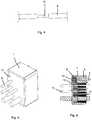
Fig. 1 is a perspective view of one example of a frame according to the present invention;Fig. 2 is a front view of the frame ofFig. 1 ;Fig. 3 is a sectional view along the lines A-A ofFig. 2 , but with one cable received;Fig. 4 is a cable set up to be received in shielded form in the frame;Fig. 5 is a perspective view of one further example of a frame according to the present invention;Fig. 6 is a sectional view corresponding toFig. 3 of the frame ofFig. 5 ;Fig. 7 is a schematic view of one example of a part of the frame according to the present invention; andFig. 8 is a schematic view of a further example of a part of the frame according to the present invention.- In
Figs. 1 to 3 of the drawings one example of aframe 1 is shown, which frame is to be received in a wall or other partition (not shown). Inside the frame 1 a number ofmodules 2 are received at each end of theframe 1, whichmodules 2 are made of an elastic material. At least onecompression unit 3, here in the form of a wedge, is arranged in connection with themodules 2 at each end of theframe 1 to compress themodules 2. By the compression exerted by the wedge by means ofscrews 4 and astay plate 7 themodules 2 will be compressed and give a tight seal, as is well known by a person skilled in the art. - A person skilled in the art realises that the exact design of the frame, modules, stay plates and compression unit is not critical and that the number of modules, compression units and stay plates received in the frame may vary. Thus, many different types of frames, modules, stay plates and compression units may be used.
- In the shown embodiment each
module 2 is formed of two halves brought together and showing acentral blind 5 and a number ofpeelable sheets 6. Even if standard modules are indicated in the drawings, a person skilled in the art realises that different types of EMC modules may also be used. - Between the
modules 2 andcompression units 3 at each end of the frame a void is formed. Said void is filled with alayer 8 of interwoven metal threads, as indicated inFig. 3 , or metal threads placed in an amorphous bunch. The metal threads may be made of any conductive material. In one embodiment steel wool is used. In other embodiments thelayer 8 of conductive material has the form of ahoneycomb structure 12, severalintermeshed nets 13 etc. Examples of ahoneycomb structure 12 and intermeshed nets are indicated inFigs. 7 and 8 , respectively. Ifnets 13 orhoneycomb structures 12 are used an opening is formed for each cable or pipe in thenets 13 orhoneycomb structure 12, before receiving acable 9 or pipe. In still other embodiments pads of one or more metal threads are formed. Such pads may be formed in that one thread is wound around a core. After suitable winding the core is removed and the formed coil is flattened into a pad. As a pad formed in this way will be rather elastic it may be placed with a press fit in theframe 1. In still a further embodiment the conductive material has the form of needle-felt mat, which needle-felt is made of a suitable conductive material. If a lose bunch of threads is used it is up to the person making the installation to see to it that enough conductive material is placed inside the frame. However, by using pads or mats of standardized size it does not have to be left to the skill of the person making the installation to see that a proper amount of conductive material is inserted. Normally the pads are slightly oversized to guarantee contact with the cables or pipes. - Before a
cable 9 is placed in the frame the outer shield of thecable 9 is taken away to expose acable screen 10. The length of the exposedcable screen 10 is adapted to the length of the void, i.e. the distance between the barriers ofmodules 2 andwedges 3 at each end of theframe 1. More precisely the length of the exposedcable screen 10 is adapted to the thickness of thelayer 8 of conductive material. Hereby, thecable screen 10 will come into contact with thelayer 8 of metal threads inside theframe 1. Thelayer 8 of metal threads and thus the exposedcable screens 10 are grounded to the frame. The size of the area of contact between thecable screen 10 and thelayer 8 of conductive material influences the damping effect. - Grounding of the
frame 1 may be accomplished in many different ways. On board ships and in many other installations the grounding is made directly in the wall or other partition receiving theframe 1. If necessary the frame may be provided with a contact for connection to earth. Normally, no special cover over thecompression unit 3 is needed for RFI protection. - In one embodiment only one barrier of
modules 2, acompression unit 3 and stayplates 7 is placed at one end of theframe 1. In the other end of theframe 1 only acover 11 is positioned to keep thelayer 8 of conductive material in place.Frames 1 with only one barrier ofmodules 2 etc. are primarily intended for installations where it is only a harsh environment on one side of theframe 1. Thecover 11 may have many different forms; it may be a plate, a net, a rubber cloth or foil, pins and/or threads attached to the frame. InFigs. 5 and 6 an example with aplate 11 as cover is indicated. - In one installation example steel wool was first placed at the bottom of the
frame 1, up to a level corresponding to half amodule 2. Then acable 9 was placed in corresponding lower module halves at each end of theframe 1, with thecable screen 10 exposed in the area between the module halves. Then the upper halves of themodules 2 were placed on top of the lower halves. Where after, further steel wool was placed on top of the steel wool at the bottom of theframe 1 and surrounding and in contact with the exposedcable screen 10. Normally, allcables 9 in one row on one level are installed simultaneous and the steel wool is placed in contact with and surrounding allcables 9. Finally astay plate 7 was placed on top of themodules 2. These steps were then repeated until the rows ofmodules 2 at each end were complete and acompression unit 3 had been placed in each barrier and the void between the barriers ofmodules 2 etc. had been filled with steel wool. The steel wool forming thelayer 8 of conductive material was placed in extended and safe contact with theouter frame 1 and with the exposedcable screen 10 of eachcable 9. - When using pads of conductive material the installation is made roughly in the same way as indicated above. Thus, first one or more pads are placed on the bottom of the
frame 1, up to a level corresponding to half amodule 2. Then the cables or pipes are normally placed in the module half or halves, where after one or more upper module halves are placed on the lower module halves. New layers of pads are then placed above the cable or pipes. This is then repeated together with possible placing of partitions, as indicated above, until the space of theframe 1 is filled. If the cables or pipes are relatively thin the flexibility of the pads may be enough to fill out the available space. However, for thicker cables and particularly thicker pipes special side pads may be placed between the frame, the other layers of pads, the pipes, and/or the cables.
Claims (13)
- Frame (1) for cable entries or pipe penetrations receiving compressible modules (2) surrounding each cable (9) or pipe received in the frame (1), which frame (1) is placed in a wall or other partition forming an opening through the wall or other partition, whereby a barrier of modules (2) are placed together with at least one compression unit (3) at one end of the frame (1) to form a seal,characterized in that a layer (8) of conductive material is placed adjacent the barrier of modules (2) inside the frame (1) and that the layer (8) of conductive material is formed of interwoven threads, nets (13), pads, honeycomb structures (12) or needle-felt mats.
- The frame (1) of claim 1,characterized in that a barrier of modules (2) comprising at least one compression unit (3) is placed at each end of the frame (1) and that the layer (8) of conductive material is placed in a void formed between the barriers of modules (2) at each end of the frame (1).
- The frame (1) of claim 1,characterized in that a cover (11) is placed at the other end of the frame (1) and that the layer (8) of conductive material is placed inside the frame (1) between the barrier of modules (2), comprising at least one compression unit (3), and the cover (11).
- The frame (1) of claim 1,characterized in that the conductive material is steel wool or other amorphous bunch of metal threads.
- The frame (1) of claim 1,characterized in that the conductive material is placed in a honeycomb structure (12) .
- The frame (1) of claim 1,characterized in that the conductive material has the form of several intermeshed nets (13).
- The frame (1) of claim 1,characterized in that the conductive material is grounded.
- The frame (1) of claim 1,characterized in that the modules are EMC modules.
- The frame (1) of claim 1,characterized in that the modules are standard modules.
- The frame (1) of claim 1,characterized in that cables (9) are received inside the modules (2) and that a cable screen (10) of each cable (9) is exposed in the area of the layer (8) of conductive material and is brought into contact with the conductive material.
- The frame (1) of claim 1,characterized in that the layer (8) of conductive material is brought into contact with the frame (1).
- The frame (1) of claim 1,characterized in that pipes are received inside the modules (2) of the frame (1).
- The frame (1) of claim 1,characterized in that if pipes or cables not including parts of conductive material are used, the parts of said pipes or cables are provided with conductive material in the area of the layer (8) of conductive material inside the frame (1) or other type of wave guide.
Priority Applications (1)
| Application Number | Priority Date | Filing Date | Title |
|---|---|---|---|
| PL06748002TPL1886390T3 (en) | 2005-05-30 | 2006-05-29 | Shielded frame |
Applications Claiming Priority (2)
| Application Number | Priority Date | Filing Date | Title |
|---|---|---|---|
| SE0501233ASE528689C2 (en) | 2005-05-30 | 2005-05-30 | Frame with shielding for cable and / or pipe penetrations in a wall or other part |
| PCT/SE2006/050162WO2006130104A1 (en) | 2005-05-30 | 2006-05-29 | Shielded frame |
Publications (3)
| Publication Number | Publication Date |
|---|---|
| EP1886390A1 EP1886390A1 (en) | 2008-02-13 |
| EP1886390A4 EP1886390A4 (en) | 2016-11-30 |
| EP1886390B1true EP1886390B1 (en) | 2018-07-18 |
Family
ID=37481938
Family Applications (1)
| Application Number | Title | Priority Date | Filing Date |
|---|---|---|---|
| EP06748002.0AActiveEP1886390B1 (en) | 2005-05-30 | 2006-05-29 | Shielded frame |
Country Status (14)
| Country | Link |
|---|---|
| US (1) | US20090194644A1 (en) |
| EP (1) | EP1886390B1 (en) |
| JP (1) | JP4875694B2 (en) |
| KR (1) | KR100949642B1 (en) |
| CN (1) | CN101185219B (en) |
| BR (1) | BRPI0609264A2 (en) |
| DK (1) | DK1886390T3 (en) |
| ES (1) | ES2687434T3 (en) |
| NO (1) | NO20075884L (en) |
| PL (1) | PL1886390T3 (en) |
| RU (1) | RU2007149525A (en) |
| SE (1) | SE528689C2 (en) |
| TW (1) | TW200822482A (en) |
| WO (1) | WO2006130104A1 (en) |
Families Citing this family (15)
| Publication number | Priority date | Publication date | Assignee | Title |
|---|---|---|---|---|
| SE532027C2 (en)* | 2008-02-15 | 2009-10-06 | Roxtec Ab | Feed-through frame with integrated compression unit |
| SE533744C2 (en) | 2009-02-04 | 2010-12-21 | Roxtec Ab | Pipe or cable entry with modularized modules |
| SE533541C2 (en)* | 2009-02-04 | 2010-10-19 | Roxtec Ab | Lubrication of a pipe or cable entry |
| SE535015C2 (en)* | 2009-02-04 | 2012-03-13 | Roxtec Ab | Compressible seal or bushing and sealing system |
| SE533818C2 (en)* | 2009-02-04 | 2011-01-25 | Roxtec Ab | Eccentric part of a pipe or cable entry |
| SE533639C2 (en)* | 2009-06-18 | 2010-11-16 | Roxtec Ab | EMC-protected compression unit and a sealing system comprising such a compression unit |
| MY159695A (en)* | 2010-09-17 | 2017-01-13 | Roxtec Ab | Modular connector for cables or pipes and system comprising such modular connector |
| DE102014006061B4 (en)* | 2014-04-25 | 2019-01-17 | Jenny Science Ag | Electrically conductive housing with cable strain relief and shield connection |
| WO2016097137A1 (en) | 2014-12-19 | 2016-06-23 | Hans-Erik Johansson I Hagstad Aktiebolag | Feed-through |
| SE539322C2 (en)* | 2015-11-18 | 2017-07-04 | Roxtec Ab | Transition and module |
| SE543123C2 (en)* | 2019-02-06 | 2020-10-13 | Roxtec Ab | Transition for an optical fiber cable |
| WO2021040632A1 (en) | 2019-08-23 | 2021-03-04 | Bi̇med Tekni̇k Aletler Sanayi̇ Ve Ti̇caret Anoni̇m Şi̇rketi̇ | Cable feedthrough element |
| EP4338246A1 (en)* | 2021-05-11 | 2024-03-20 | Roxtec AB | A retention device, system and method for holding one or more cables and use thereof |
| SE545999C2 (en)* | 2021-06-30 | 2024-04-09 | Roxtec Ab | A sealing module for cables or pipes, a transit system comprising such a sealing module, and a method of manufacturing a sealing module |
| SE545523C2 (en)* | 2021-06-30 | 2023-10-10 | Roxtec Ab | A sealing module for a cable or pipe and transit systems comprising such a sealing module |
Citations (1)
| Publication number | Priority date | Publication date | Assignee | Title |
|---|---|---|---|---|
| CA1240386A (en)* | 1984-03-23 | 1988-08-09 | Ab Lyckeaborgs Bruk | Radiation protective device for the lead-through of cables |
Family Cites Families (18)
| Publication number | Priority date | Publication date | Assignee | Title |
|---|---|---|---|---|
| DE2909890C2 (en)* | 1979-03-14 | 1982-05-27 | System- Und Verfahrenstechnik Verwaltungsgesellschaft Mbh, 2105 Seevetal | Device for shielding high-frequency electrical and electromagnetic waves in tight bushings for bundles of cables through a wall |
| DE2932612C3 (en)* | 1979-08-10 | 1982-02-04 | Siemens AG, 1000 Berlin und 8000 München | Cable shield earthing |
| US4547623A (en)* | 1983-10-07 | 1985-10-15 | Automation Industries, Inc. | Cable shield grounding apparatus |
| US4656313A (en)* | 1983-12-19 | 1987-04-07 | General Signal Corporation | EMI/EMP electrical cable penetration seal |
| GB2186443B (en)* | 1986-02-11 | 1990-06-20 | Hawke Cable Glands Ltd | Improved transit for cables and pipes |
| US5416271A (en)* | 1991-10-29 | 1995-05-16 | General Signal Corporation | Electrical cable penetration seal with compliant module |
| JPH0828759A (en)* | 1994-07-13 | 1996-02-02 | Tomoe Corp | Electromagnetic wave shield and fire-proofing piping unit |
| US6184460B1 (en)* | 1998-02-27 | 2001-02-06 | Berg Technology, Inc. | Modular box shield for forming a coaxial header |
| NL1008638C2 (en)* | 1998-03-06 | 1999-09-07 | Beele Eng Bv | Transit device. |
| DE19838951C1 (en)* | 1998-08-27 | 2000-05-04 | Schroff Gmbh | HF-tight bushing |
| NL1015895C2 (en)* | 2000-08-08 | 2002-02-12 | Beele Eng Bv | Feeding device. |
| US6375361B1 (en)* | 2000-08-21 | 2002-04-23 | Lucent Technologies Inc. | Optical fiber connector electromagnetic shield assembly |
| NL1018262C2 (en)* | 2001-06-12 | 2002-12-13 | Beele Eng Bv | Sealing system. |
| TWI258771B (en)* | 2001-12-04 | 2006-07-21 | Laird Technologies Inc | Methods and apparatus for EMI shielding |
| SE520363C2 (en)* | 2001-12-14 | 2003-07-01 | Roxtec Int Ab | Entry device for conducting elongated conduit through an opening in a wall |
| SE0200158L (en)* | 2002-01-22 | 2003-02-25 | Roxtec Int Ab | Frame, for cable entry or similar, provided with a breakable cover |
| KR200307898Y1 (en)* | 2002-10-16 | 2003-03-19 | 송양미 | The electric mat provides mat's grounding conductor woven with metal thread for breaking electromagnetic waves |
| JP4309121B2 (en)* | 2002-12-19 | 2009-08-05 | Necインフロンティア株式会社 | Noise suppression structure for shielded cable |
- 2005
- 2005-05-30SESE0501233Apatent/SE528689C2/enunknown
- 2006
- 2006-05-29KRKR1020077027831Apatent/KR100949642B1/ennot_activeExpired - Fee Related
- 2006-05-29EPEP06748002.0Apatent/EP1886390B1/enactiveActive
- 2006-05-29ESES06748002.0Tpatent/ES2687434T3/enactiveActive
- 2006-05-29WOPCT/SE2006/050162patent/WO2006130104A1/enactiveApplication Filing
- 2006-05-29BRBRPI0609264-0Apatent/BRPI0609264A2/ennot_activeIP Right Cessation
- 2006-05-29PLPL06748002Tpatent/PL1886390T3/enunknown
- 2006-05-29RURU2007149525/09Apatent/RU2007149525A/enunknown
- 2006-05-29JPJP2008502951Apatent/JP4875694B2/ennot_activeExpired - Fee Related
- 2006-05-29CNCN2006800189765Apatent/CN101185219B/ennot_activeExpired - Fee Related
- 2006-05-29DKDK06748002.0Tpatent/DK1886390T3/enactive
- 2006-05-29USUS11/918,922patent/US20090194644A1/ennot_activeAbandoned
- 2006-11-03TWTW095140724Apatent/TW200822482A/enunknown
- 2007
- 2007-11-15NONO20075884Apatent/NO20075884L/ennot_activeApplication Discontinuation
Patent Citations (1)
| Publication number | Priority date | Publication date | Assignee | Title |
|---|---|---|---|---|
| CA1240386A (en)* | 1984-03-23 | 1988-08-09 | Ab Lyckeaborgs Bruk | Radiation protective device for the lead-through of cables |
Also Published As
| Publication number | Publication date |
|---|---|
| JP4875694B2 (en) | 2012-02-15 |
| SE0501233L (en) | 2006-12-01 |
| KR20080009145A (en) | 2008-01-24 |
| SE528689C2 (en) | 2007-01-23 |
| CN101185219A (en) | 2008-05-21 |
| US20090194644A1 (en) | 2009-08-06 |
| NO20075884L (en) | 2007-11-15 |
| WO2006130104A1 (en) | 2006-12-07 |
| CN101185219B (en) | 2010-11-17 |
| EP1886390A1 (en) | 2008-02-13 |
| TW200822482A (en) | 2008-05-16 |
| RU2007149525A (en) | 2009-07-10 |
| JP2008533748A (en) | 2008-08-21 |
| ES2687434T3 (en) | 2018-10-25 |
| KR100949642B1 (en) | 2010-03-26 |
| EP1886390A4 (en) | 2016-11-30 |
| BRPI0609264A2 (en) | 2010-03-09 |
| DK1886390T3 (en) | 2018-10-15 |
| PL1886390T3 (en) | 2018-12-31 |
Similar Documents
| Publication | Publication Date | Title |
|---|---|---|
| EP1886390B1 (en) | Shielded frame | |
| US8598472B2 (en) | EMC protected compression unit and a sealing system comprising such compression unit | |
| US9407031B2 (en) | Modular connector for cables or pipes and system comprising such modular connector | |
| US6717047B2 (en) | EMI enclosure having a flexible cable shield | |
| JP7743404B2 (en) | Transit for passing at least one cable and/or at least one metal pipe | |
| HK40011473A (en) | Modular connector for cables or pipes and system comprising such modular connector | |
| HK1172741A (en) | Modular connector for cables or pipes and system comprising such modular connector |
Legal Events
| Date | Code | Title | Description |
|---|---|---|---|
| PUAI | Public reference made under article 153(3) epc to a published international application that has entered the european phase | Free format text:ORIGINAL CODE: 0009012 | |
| 17P | Request for examination filed | Effective date:20071213 | |
| AK | Designated contracting states | Kind code of ref document:A1 Designated state(s):AT BE BG CH CY CZ DE DK EE ES FI FR GB GR HU IE IS IT LI LT LU LV MC NL PL PT RO SE SI SK TR | |
| DAX | Request for extension of the european patent (deleted) | ||
| RA4 | Supplementary search report drawn up and despatched (corrected) | Effective date:20161027 | |
| RIC1 | Information provided on ipc code assigned before grant | Ipc:F16L 5/14 20060101ALI20161021BHEP Ipc:F16L 5/08 20060101ALI20161021BHEP Ipc:H02G 3/22 20060101AFI20161021BHEP Ipc:H05K 9/00 20060101ALI20161021BHEP | |
| RIC1 | Information provided on ipc code assigned before grant | Ipc:H02G 3/22 20060101AFI20180207BHEP Ipc:F16L 5/14 20060101ALI20180207BHEP Ipc:H05K 9/00 20060101ALI20180207BHEP Ipc:F16L 5/08 20060101ALI20180207BHEP | |
| GRAP | Despatch of communication of intention to grant a patent | Free format text:ORIGINAL CODE: EPIDOSNIGR1 | |
| STAA | Information on the status of an ep patent application or granted ep patent | Free format text:STATUS: GRANT OF PATENT IS INTENDED | |
| INTG | Intention to grant announced | Effective date:20180322 | |
| RAP1 | Party data changed (applicant data changed or rights of an application transferred) | Owner name:ROXTEC AB | |
| GRAS | Grant fee paid | Free format text:ORIGINAL CODE: EPIDOSNIGR3 | |
| GRAA | (expected) grant | Free format text:ORIGINAL CODE: 0009210 | |
| STAA | Information on the status of an ep patent application or granted ep patent | Free format text:STATUS: THE PATENT HAS BEEN GRANTED | |
| AK | Designated contracting states | Kind code of ref document:B1 Designated state(s):AT BE BG CH CY CZ DE DK EE ES FI FR GB GR HU IE IS IT LI LT LU LV MC NL PL PT RO SE SI SK TR | |
| REG | Reference to a national code | Ref country code:GB Ref legal event code:FG4D | |
| REG | Reference to a national code | Ref country code:CH Ref legal event code:EP | |
| REG | Reference to a national code | Ref country code:IE Ref legal event code:FG4D | |
| REG | Reference to a national code | Ref country code:AT Ref legal event code:REF Ref document number:1020381 Country of ref document:AT Kind code of ref document:T Effective date:20180815 | |
| REG | Reference to a national code | Ref country code:DE Ref legal event code:R096 Ref document number:602006055846 Country of ref document:DE | |
| REG | Reference to a national code | Ref country code:DK Ref legal event code:T3 Effective date:20181008 | |
| REG | Reference to a national code | Ref country code:NL Ref legal event code:FP | |
| REG | Reference to a national code | Ref country code:ES Ref legal event code:FG2A Ref document number:2687434 Country of ref document:ES Kind code of ref document:T3 Effective date:20181025 | |
| REG | Reference to a national code | Ref country code:LT Ref legal event code:MG4D | |
| PG25 | Lapsed in a contracting state [announced via postgrant information from national office to epo] | Ref country code:LT Free format text:LAPSE BECAUSE OF FAILURE TO SUBMIT A TRANSLATION OF THE DESCRIPTION OR TO PAY THE FEE WITHIN THE PRESCRIBED TIME-LIMIT Effective date:20180718 Ref country code:SE Free format text:LAPSE BECAUSE OF FAILURE TO SUBMIT A TRANSLATION OF THE DESCRIPTION OR TO PAY THE FEE WITHIN THE PRESCRIBED TIME-LIMIT Effective date:20180718 Ref country code:BG Free format text:LAPSE BECAUSE OF FAILURE TO SUBMIT A TRANSLATION OF THE DESCRIPTION OR TO PAY THE FEE WITHIN THE PRESCRIBED TIME-LIMIT Effective date:20181018 Ref country code:GR Free format text:LAPSE BECAUSE OF FAILURE TO SUBMIT A TRANSLATION OF THE DESCRIPTION OR TO PAY THE FEE WITHIN THE PRESCRIBED TIME-LIMIT Effective date:20181019 Ref country code:IS Free format text:LAPSE BECAUSE OF FAILURE TO SUBMIT A TRANSLATION OF THE DESCRIPTION OR TO PAY THE FEE WITHIN THE PRESCRIBED TIME-LIMIT Effective date:20181118 | |
| PG25 | Lapsed in a contracting state [announced via postgrant information from national office to epo] | Ref country code:LV Free format text:LAPSE BECAUSE OF FAILURE TO SUBMIT A TRANSLATION OF THE DESCRIPTION OR TO PAY THE FEE WITHIN THE PRESCRIBED TIME-LIMIT Effective date:20180718 | |
| REG | Reference to a national code | Ref country code:DE Ref legal event code:R097 Ref document number:602006055846 Country of ref document:DE | |
| PG25 | Lapsed in a contracting state [announced via postgrant information from national office to epo] | Ref country code:CZ Free format text:LAPSE BECAUSE OF FAILURE TO SUBMIT A TRANSLATION OF THE DESCRIPTION OR TO PAY THE FEE WITHIN THE PRESCRIBED TIME-LIMIT Effective date:20180718 Ref country code:RO Free format text:LAPSE BECAUSE OF FAILURE TO SUBMIT A TRANSLATION OF THE DESCRIPTION OR TO PAY THE FEE WITHIN THE PRESCRIBED TIME-LIMIT Effective date:20180718 Ref country code:EE Free format text:LAPSE BECAUSE OF FAILURE TO SUBMIT A TRANSLATION OF THE DESCRIPTION OR TO PAY THE FEE WITHIN THE PRESCRIBED TIME-LIMIT Effective date:20180718 | |
| PLBE | No opposition filed within time limit | Free format text:ORIGINAL CODE: 0009261 | |
| STAA | Information on the status of an ep patent application or granted ep patent | Free format text:STATUS: NO OPPOSITION FILED WITHIN TIME LIMIT | |
| PG25 | Lapsed in a contracting state [announced via postgrant information from national office to epo] | Ref country code:SK Free format text:LAPSE BECAUSE OF FAILURE TO SUBMIT A TRANSLATION OF THE DESCRIPTION OR TO PAY THE FEE WITHIN THE PRESCRIBED TIME-LIMIT Effective date:20180718 | |
| 26N | No opposition filed | Effective date:20190423 | |
| PGFP | Annual fee paid to national office [announced via postgrant information from national office to epo] | Ref country code:NL Payment date:20190515 Year of fee payment:14 | |
| PGFP | Annual fee paid to national office [announced via postgrant information from national office to epo] | Ref country code:DE Payment date:20190514 Year of fee payment:14 Ref country code:DK Payment date:20190510 Year of fee payment:14 Ref country code:ES Payment date:20190603 Year of fee payment:14 Ref country code:PL Payment date:20190430 Year of fee payment:14 | |
| PG25 | Lapsed in a contracting state [announced via postgrant information from national office to epo] | Ref country code:SI Free format text:LAPSE BECAUSE OF FAILURE TO SUBMIT A TRANSLATION OF THE DESCRIPTION OR TO PAY THE FEE WITHIN THE PRESCRIBED TIME-LIMIT Effective date:20180718 | |
| PGFP | Annual fee paid to national office [announced via postgrant information from national office to epo] | Ref country code:TR Payment date:20190517 Year of fee payment:14 Ref country code:FR Payment date:20190429 Year of fee payment:14 | |
| PGFP | Annual fee paid to national office [announced via postgrant information from national office to epo] | Ref country code:AT Payment date:20190425 Year of fee payment:14 Ref country code:GB Payment date:20190529 Year of fee payment:14 | |
| REG | Reference to a national code | Ref country code:CH Ref legal event code:PL | |
| PG25 | Lapsed in a contracting state [announced via postgrant information from national office to epo] | Ref country code:LI Free format text:LAPSE BECAUSE OF NON-PAYMENT OF DUE FEES Effective date:20190531 Ref country code:MC Free format text:LAPSE BECAUSE OF FAILURE TO SUBMIT A TRANSLATION OF THE DESCRIPTION OR TO PAY THE FEE WITHIN THE PRESCRIBED TIME-LIMIT Effective date:20180718 Ref country code:CH Free format text:LAPSE BECAUSE OF NON-PAYMENT OF DUE FEES Effective date:20190531 | |
| REG | Reference to a national code | Ref country code:BE Ref legal event code:MM Effective date:20190531 | |
| PG25 | Lapsed in a contracting state [announced via postgrant information from national office to epo] | Ref country code:LU Free format text:LAPSE BECAUSE OF NON-PAYMENT OF DUE FEES Effective date:20190529 | |
| PG25 | Lapsed in a contracting state [announced via postgrant information from national office to epo] | Ref country code:IE Free format text:LAPSE BECAUSE OF NON-PAYMENT OF DUE FEES Effective date:20190529 | |
| PG25 | Lapsed in a contracting state [announced via postgrant information from national office to epo] | Ref country code:BE Free format text:LAPSE BECAUSE OF NON-PAYMENT OF DUE FEES Effective date:20190531 | |
| PG25 | Lapsed in a contracting state [announced via postgrant information from national office to epo] | Ref country code:PT Free format text:LAPSE BECAUSE OF FAILURE TO SUBMIT A TRANSLATION OF THE DESCRIPTION OR TO PAY THE FEE WITHIN THE PRESCRIBED TIME-LIMIT Effective date:20181118 | |
| REG | Reference to a national code | Ref country code:DE Ref legal event code:R119 Ref document number:602006055846 Country of ref document:DE | |
| REG | Reference to a national code | Ref country code:FI Ref legal event code:MAE | |
| REG | Reference to a national code | Ref country code:DK Ref legal event code:EBP Effective date:20200531 | |
| REG | Reference to a national code | Ref country code:NL Ref legal event code:MM Effective date:20200601 | |
| REG | Reference to a national code | Ref country code:AT Ref legal event code:MM01 Ref document number:1020381 Country of ref document:AT Kind code of ref document:T Effective date:20200529 | |
| PG25 | Lapsed in a contracting state [announced via postgrant information from national office to epo] | Ref country code:FI Free format text:LAPSE BECAUSE OF NON-PAYMENT OF DUE FEES Effective date:20200529 Ref country code:AT Free format text:LAPSE BECAUSE OF NON-PAYMENT OF DUE FEES Effective date:20200529 | |
| PG25 | Lapsed in a contracting state [announced via postgrant information from national office to epo] | Ref country code:NL Free format text:LAPSE BECAUSE OF NON-PAYMENT OF DUE FEES Effective date:20200601 | |
| GBPC | Gb: european patent ceased through non-payment of renewal fee | Effective date:20200529 | |
| PG25 | Lapsed in a contracting state [announced via postgrant information from national office to epo] | Ref country code:FR Free format text:LAPSE BECAUSE OF NON-PAYMENT OF DUE FEES Effective date:20200531 Ref country code:GB Free format text:LAPSE BECAUSE OF NON-PAYMENT OF DUE FEES Effective date:20200529 Ref country code:DK Free format text:LAPSE BECAUSE OF NON-PAYMENT OF DUE FEES Effective date:20200531 | |
| PG25 | Lapsed in a contracting state [announced via postgrant information from national office to epo] | Ref country code:DE Free format text:LAPSE BECAUSE OF NON-PAYMENT OF DUE FEES Effective date:20201201 Ref country code:CY Free format text:LAPSE BECAUSE OF FAILURE TO SUBMIT A TRANSLATION OF THE DESCRIPTION OR TO PAY THE FEE WITHIN THE PRESCRIBED TIME-LIMIT Effective date:20180718 | |
| PG25 | Lapsed in a contracting state [announced via postgrant information from national office to epo] | Ref country code:HU Free format text:LAPSE BECAUSE OF FAILURE TO SUBMIT A TRANSLATION OF THE DESCRIPTION OR TO PAY THE FEE WITHIN THE PRESCRIBED TIME-LIMIT; INVALID AB INITIO Effective date:20060529 | |
| REG | Reference to a national code | Ref country code:ES Ref legal event code:FD2A Effective date:20211004 | |
| PG25 | Lapsed in a contracting state [announced via postgrant information from national office to epo] | Ref country code:ES Free format text:LAPSE BECAUSE OF NON-PAYMENT OF DUE FEES Effective date:20200530 | |
| REG | Reference to a national code | Ref country code:AT Ref legal event code:UEP Ref document number:1020381 Country of ref document:AT Kind code of ref document:T Effective date:20180718 | |
| PG25 | Lapsed in a contracting state [announced via postgrant information from national office to epo] | Ref country code:TR Free format text:LAPSE BECAUSE OF NON-PAYMENT OF DUE FEES Effective date:20200529 | |
| PG25 | Lapsed in a contracting state [announced via postgrant information from national office to epo] | Ref country code:PL Free format text:LAPSE BECAUSE OF NON-PAYMENT OF DUE FEES Effective date:20200529 | |
| P01 | Opt-out of the competence of the unified patent court (upc) registered | Effective date:20230503 | |
| PGFP | Annual fee paid to national office [announced via postgrant information from national office to epo] | Ref country code:IT Payment date:20250507 Year of fee payment:20 |