EP1885435B1 - Trans-septal/trans-myocardial ventricular pacing lead - Google Patents
Trans-septal/trans-myocardial ventricular pacing leadDownload PDFInfo
- Publication number
- EP1885435B1 EP1885435B1EP06740193AEP06740193AEP1885435B1EP 1885435 B1EP1885435 B1EP 1885435B1EP 06740193 AEP06740193 AEP 06740193AEP 06740193 AEP06740193 AEP 06740193AEP 1885435 B1EP1885435 B1EP 1885435B1
- Authority
- EP
- European Patent Office
- Prior art keywords
- lead
- distal end
- electrode
- heart
- fabric
- Prior art date
- Legal status (The legal status is an assumption and is not a legal conclusion. Google has not performed a legal analysis and makes no representation as to the accuracy of the status listed.)
- Not-in-force
Links
- 230000002861ventricularEffects0.000titledescription20
- 239000004744fabricSubstances0.000claimsabstractdescription37
- 239000004020conductorSubstances0.000claimsabstractdescription21
- 230000000638stimulationEffects0.000claimsabstractdescription6
- 210000005240left ventricleAnatomy0.000claimsdescription29
- 238000003780insertionMethods0.000claimsdescription15
- 230000037431insertionEffects0.000claimsdescription15
- 239000000463materialSubstances0.000claimsdescription7
- 238000002513implantationMethods0.000claimsdescription6
- 208000025339heart septal defectDiseases0.000abstract1
- 230000004913activationEffects0.000description18
- 210000005241right ventricleAnatomy0.000description18
- 238000013459approachMethods0.000description14
- 210000001174endocardiumAnatomy0.000description7
- 230000035515penetrationEffects0.000description7
- 206010006580Bundle branch block leftDiseases0.000description6
- 206010006578Bundle-Branch BlockDiseases0.000description6
- 201000001715left bundle branch hemiblockDiseases0.000description6
- 230000000694effectsEffects0.000description5
- 238000000034methodMethods0.000description5
- 210000000596ventricular septumAnatomy0.000description5
- 206010019280Heart failuresDiseases0.000description4
- 229910001000nickel titaniumInorganic materials0.000description4
- 239000000560biocompatible materialSubstances0.000description3
- 238000010586diagramMethods0.000description3
- 230000004217heart functionEffects0.000description3
- 238000009413insulationMethods0.000description3
- 230000028161membrane depolarizationEffects0.000description3
- 230000002107myocardial effectEffects0.000description3
- 229920002635polyurethanePolymers0.000description3
- 239000004814polyurethaneSubstances0.000description3
- 210000005245right atriumAnatomy0.000description3
- 210000001519tissueAnatomy0.000description3
- 206010003671Atrioventricular BlockDiseases0.000description2
- 229920004934Dacron®Polymers0.000description2
- PXHVJJICTQNCMI-UHFFFAOYSA-NNickelChemical compound[Ni]PXHVJJICTQNCMI-UHFFFAOYSA-N0.000description2
- 238000004873anchoringMethods0.000description2
- 206010003119arrhythmiaDiseases0.000description2
- 230000000903blocking effectEffects0.000description2
- 210000001124body fluidAnatomy0.000description2
- 239000010839body fluidSubstances0.000description2
- 150000001875compoundsChemical class0.000description2
- 210000002837heart atriumAnatomy0.000description2
- 238000004519manufacturing processMethods0.000description2
- HLXZNVUGXRDIFK-UHFFFAOYSA-Nnickel titaniumChemical compound[Ti].[Ti].[Ti].[Ti].[Ti].[Ti].[Ti].[Ti].[Ti].[Ti].[Ti].[Ni].[Ni].[Ni].[Ni].[Ni].[Ni].[Ni].[Ni].[Ni].[Ni].[Ni].[Ni].[Ni].[Ni]HLXZNVUGXRDIFK-UHFFFAOYSA-N0.000description2
- 239000005020polyethylene terephthalateSubstances0.000description2
- 238000007634remodelingMethods0.000description2
- 231100000241scarToxicity0.000description2
- 229920000260silasticPolymers0.000description2
- 238000002560therapeutic procedureMethods0.000description2
- 210000003462veinAnatomy0.000description2
- 208000002330Congenital Heart DefectsDiseases0.000description1
- 229910000990Ni alloyInorganic materials0.000description1
- 206010040639Sick sinus syndromeDiseases0.000description1
- FAPWRFPIFSIZLT-UHFFFAOYSA-MSodium chlorideChemical compound[Na+].[Cl-]FAPWRFPIFSIZLT-UHFFFAOYSA-M0.000description1
- 229910000831SteelInorganic materials0.000description1
- 229910001069Ti alloyInorganic materials0.000description1
- 208000033774Ventricular RemodelingDiseases0.000description1
- 230000009471actionEffects0.000description1
- 239000003146anticoagulant agentSubstances0.000description1
- 229940127219anticoagulant drugDrugs0.000description1
- 230000006793arrhythmiaEffects0.000description1
- 210000003157atrial septumAnatomy0.000description1
- 238000005452bendingMethods0.000description1
- 230000009286beneficial effectEffects0.000description1
- 230000015572biosynthetic processEffects0.000description1
- 230000000747cardiac effectEffects0.000description1
- 238000009125cardiac resynchronization therapyMethods0.000description1
- 210000004903cardiac systemAnatomy0.000description1
- 230000008602contractionEffects0.000description1
- 210000003748coronary sinusAnatomy0.000description1
- 238000001514detection methodMethods0.000description1
- 238000006073displacement reactionMethods0.000description1
- 229940079593drugDrugs0.000description1
- 239000003814drugSubstances0.000description1
- 230000009977dual effectEffects0.000description1
- 238000002474experimental methodMethods0.000description1
- 239000000835fiberSubstances0.000description1
- 230000006870functionEffects0.000description1
- 230000005831heart abnormalityEffects0.000description1
- 210000005003heart tissueAnatomy0.000description1
- 230000023597hemostasisEffects0.000description1
- 239000007943implantSubstances0.000description1
- 238000009434installationMethods0.000description1
- 210000005246left atriumAnatomy0.000description1
- 210000004115mitral valveAnatomy0.000description1
- 230000010287polarizationEffects0.000description1
- 230000033764rhythmic processEffects0.000description1
- 210000005247right atrial appendageAnatomy0.000description1
- 238000007789sealingMethods0.000description1
- 229920002379silicone rubberPolymers0.000description1
- 210000001013sinoatrial nodeAnatomy0.000description1
- 239000010959steelSubstances0.000description1
- 238000001356surgical procedureMethods0.000description1
- 230000001360synchronised effectEffects0.000description1
- 230000001839systemic circulationEffects0.000description1
- 208000003663ventricular fibrillationDiseases0.000description1
- 238000003466weldingMethods0.000description1
Images


Classifications
- A—HUMAN NECESSITIES
- A61—MEDICAL OR VETERINARY SCIENCE; HYGIENE
- A61N—ELECTROTHERAPY; MAGNETOTHERAPY; RADIATION THERAPY; ULTRASOUND THERAPY
- A61N1/00—Electrotherapy; Circuits therefor
- A61N1/02—Details
- A61N1/04—Electrodes
- A61N1/05—Electrodes for implantation or insertion into the body, e.g. heart electrode
- A61N1/056—Transvascular endocardial electrode systems
- A61N1/057—Anchoring means; Means for fixing the head inside the heart
- A—HUMAN NECESSITIES
- A61—MEDICAL OR VETERINARY SCIENCE; HYGIENE
- A61N—ELECTROTHERAPY; MAGNETOTHERAPY; RADIATION THERAPY; ULTRASOUND THERAPY
- A61N1/00—Electrotherapy; Circuits therefor
- A61N1/02—Details
- A61N1/04—Electrodes
- A61N1/05—Electrodes for implantation or insertion into the body, e.g. heart electrode
- A61N1/0587—Epicardial electrode systems; Endocardial electrodes piercing the pericardium
- A—HUMAN NECESSITIES
- A61—MEDICAL OR VETERINARY SCIENCE; HYGIENE
- A61N—ELECTROTHERAPY; MAGNETOTHERAPY; RADIATION THERAPY; ULTRASOUND THERAPY
- A61N1/00—Electrotherapy; Circuits therefor
- A61N1/02—Details
- A61N1/04—Electrodes
- A61N1/05—Electrodes for implantation or insertion into the body, e.g. heart electrode
- A61N1/056—Transvascular endocardial electrode systems
- A61N1/057—Anchoring means; Means for fixing the head inside the heart
- A61N1/0573—Anchoring means; Means for fixing the head inside the heart chacterised by means penetrating the heart tissue, e.g. helix needle or hook
Definitions
- the present teachingrelates to an implantable apparatus for treating cardiac arrhythmia, particularly ventricular fibrillation. More particularly, the present teachings relate to an implantable apparatus for cardiac resynchronization therapy to heart failure patients.
- pacing leadshave been developed for endocardial implant, typically in the right ventricle (RV) or right atrial appendage, as well as the coronary sinus.
- These flexible leadsusually are constructed having an outer polymeric sheath encasing one or more electrical conductors.
- One conductoris typically attached at its distal tip to the shank portion of a tip electrode.
- one or more further conductorsare provided in coaxial or co-linear relation to the first conductor and is connected at its distal end to a more proximally located, ring-shaped electrode situated along the lead body.
- each conductoris coupled to a connector, which includes a single pin in unipolar leads, and additional pins or in-line rings in bipolar and multipolar leads.
- a connectorwhich includes a single pin in unipolar leads, and additional pins or in-line rings in bipolar and multipolar leads.
- US 5 336 252discloses an implantable medical electrical lead according to the preamble of claim 1.
- Stimulation in both single chamber and dual chamber pacemakers with ventricular stimulationnormally takes place in the apex of the RV.
- a conventional pacemaker of this typetypically requires two electrodes. One of these electrodes is placed in the right atrium (RA) and the other in the apex of the RV. The electrodes sense electrical activity in the heart and provide stimulation pulses as needed to rectify arrhythmias.
- SAsinoatrial
- AVatrioventricular
- Purkinge fibersThis provides a sequential activation of the atria and the ventricles. Specifically, the sequential polarization and depolarization of the atria and the ventricle results in a naturally synchronized sinus rhythm.
- LV activationleft ventricle activation before RV activation
- endocardial activationbefore epicardial activation
- apex activationbefore base activation.
- the earliest electrical activationtypically occurs at the endocardium of the lower left side of the septum and the lower anterior wall.
- ventricular pacingis to resynchronize the ventricular activation. This is mainly used in patients with heart failure (HF) who also have left bundle branch block (LBBB). LBBB causes a sequence of activation similar to that during RV apex pacing. In the LBBB patients, left ventricular (LV) or biventricular pacing (BiV) is used to resynchronize ventricular activation, with good results.
- LVleft ventricular
- BiVbiventricular pacing
- LV pacing sitesmay offer great advantages over RV pacing sites, positioning of the leads is cumbersome. For example, thoracotomy is used to position a lead at the LV wall, but this invasive procedure does not offer significant advantages over the transvenous approach. In the transvenous approach, LV pacing leads are positioned in coronary veins, which can be difficult, time consuming, and not reliable because of lead displacement. Moreover, even if the lead can be positioned in a coronary vein, individual heart anatomies differ widely, such that the preferred site could be difficult to locate for lead replacement.
- trans-atrial septal approachwas introduced to enable LV endocardial pacing.
- the pacing leadis advanced from the right atrium through the right atrial septum wall into the left atrium and through the mitral valve into the LV cavity until a proper site at the LV endocardium is reached.
- a disadvantage with this approachis that a large part of the lead is permanently inside of the LV cavity.
- One of the many clinical concerns with the trans-atrial septal approachis Emboli originating from this lead may enter the systemic circulation giving rise to strokes.
- the inventionprovides a medical electrical lead as defined in claim 1.
- the lead systemincludes attachment means into the transventricular system to attach to a location in the LV.
- the lead systemis introduced from the RV side and enables a more reliable site selection in the LV and provides a secure semi-exogenous lead attachment to the LV.
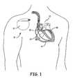
- IMD 10 shown in FIG. 1is a pacemaker comprising at least one of pacing and sensing leads 14, 22, 30, and 40 attached to hermetically sealed enclosure 11 and implanted near human or mammalian heart 12.
- Pacing and sensing leads 14, 22, 30, and 40sense electrical signals attendant to the depolarization and re-polarization of heart 12, and further provide pacing pulses for causing depolarization of cardiac tissue in the vicinity of the distal ends thereof.
- Leads 14, 22, 30, and 40may have unipolar or bipolar electrodes disposed thereon, as is well known in the art.
- Examples of IMD 10include implantable cardiac pacemakers disclosed in U.S. Pat. No. 5,158,078 to Bennett et al ., U.S. Pat. No. 5,312,453 to Shelton et al . or U.S. Pat. No. 5,144,949 to Olson .
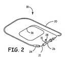
- Lead assembly 18comprises guide catheter 20 and lead body 21.
- Lead body 21is received by and fits slidingly within guide catheter 20.
- Hub 24is located at the proximal end of guide catheter 20.
- Hemostasis valve 26may be attached to the proximal end of hub 24. Removal of sealing cap 28 from neck 31 permits the introduction of saline solution, anticoagulants, and intravenously administered drugs through valve 26.
- the proximal end of valve 26receives lead body 21 and guides it through hub 24 into guide catheter 20.
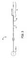
- Lead body 21has a proximal end 36 with a conductor 54 ( Figure 4 ) for establishing electrical connection between lead assembly 18, an IMD 10, and the tissue of heart 12.
- Electrically insulative outer sheath 50is formed of biocompatible material such as a suitable polyurethane or silastic compound, and protects electrical conductor 54 disposed within lead body 21 from the corrosive effects presented by body fluids. Sheath 50 additionally prevents conductor 54 disposed within lead body 21 from shorting to the body. It is fully contemplated there can be more than one connector, as is discussed below.
- Conductor 54can be three strands of left-hand-wound twisted MP35-N wire, and can be capable of reliably conducting electrical current after having been subjected to numerous, repeated bending and torquing stresses. However, conductor 54 may comprise a single wire formed of a nickel-titanium alloy such as nitinol. Lead body 21 has a diameter of about 3 French in some embodiments, but may have a diameter as great as about 4 French or as small as about 2 French. Conductor 54 is mechanically and electrically connected to electrode 66.
- Conductor 54 and electrode 66can be connected by laser welding however other methods of connection are contemplated.
- Operably coupled to electrode 66is an occlusion fabric 104.
- Occlusion fabric 104can be made of most any type of material as long as the material can be implanted within the body.
- occlusion fabric 104could be made of Dacron.
- occlusion fabric 104could be attached to electrode 66 in a plurality of ways, such as stitching fabric 104 to electrode 66 or fabric 104 could have pockets to receive the electrode 66. Regardless of how electrode 66 is coupled to fabric 104, it is beneficial for portions of the surface of electrode 66 to be exposed to provide good electrical conductivity to heart 12.
- a trans-septal pacing approach using a pacing lead in an embodiment of the present teachingsis shown.
- the present teachingdiscloses positioning a pacing lead in heart 12 at septum 100 or at myocardial wall 102.
- a trans-septal pacing approacha standard transvenous entrance is used to advance lead 18 towards ventricular septum 100.
- the same transvenous entrancewould be used to advance a pacing lead 19 to the base of right ventricle 106 to pace the right ventricle as is know in the art. From there lead 18 penetrates ventricular septum 100 until the lead protrudes into the LV cavity.
- lead 18is withdrawn, until electrode 66 is against the left septal endocardium 100 and occlusion fabric 104 operably coupled to electrode 66 rests against the left septal endocardium blocking the hole created during penetration of ventricular septum 100 by lead 18.
- This arrangementplaces the lead in an embedded position in the transventricular system, which enables sensing, detection, and pacing in the LV.
- the lower part of the LV septumis substantially the general location where activation starts in the normal heartbeat. With trans-septal pacing the electrical impulse will presumably spread from the septal apex to the base, from endocardium to epicardium and cause the LV side of the septum to be activated before the RV.
- trans-septal pacingcombines a relatively easy implantation procedure with minimal risk for formation of emboli and with a sequence of activation similar to the normal activation pattern. The latter will result in optimal LV ejection fraction and minimized remodeling as compared to RV apex pacing.
- a trans-myocardial pacing approach using a pacing lead in an embodiment of the present teachingsis shown.
- a trans-myocardial pacing approacha standard surgical procedure is used to advance lead 18 towards ventricular myocardial wall 102. From there lead 18 penetrates ventricular wall 102 until the lead enters the LV cavity. Then lead 18 is withdrawn, until electrode 66 is against the left septal endocardium and an occlusion fabric 104 operably coupled to electrode 66 rests against the left septal endocardium blocking the puncture created during penetration of the ventricular septum by lead 18.
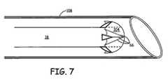
- a heart wall penetration system for delivery of a pacing lead in an embodiment of the present teachingsis shown.
- Penetration of septum 100 or heart wall 102could be accomplished in a plurality of ways; however, for the purpose of the disclosure penetration will be discussed with respect to a catheter.
- a stiff, curved guide catheter 108can be positioned into right ventricle 106 or close to ventricular wall 102. Through catheter 108 a force can be applied to penetrate ventricular septum 100 or ventricular wall 102.
- penetration of septum 100 or heart wall 102can be accomplished in a plurality of ways such as by advancing a sharp steel wire, thus creating a hole, then withdrawing the wire and introducing the pacing lead through the hole, with a pacing lead having a sharp tip, or by placing a stiffening stylet in a pacing lead that makes the lead stiff enough to penetrate the heart wall.
- right ventricle pacingmaintains normal ventricular activation in case of AV-block or sick sinus syndrome. In these patients cardiac function can be better maintained and remodeling of the heart is likely prevented or reduced. Moreover, since the right ventricular pacing site is likely distal to the block in the case of Left Branch Bundle Block (LBBB), right ventricle pacing may also be used for resynchronization therapy in heart failure LBBB pacing, instead of the coronary venous approach.
- LBBBLeft Branch Bundle Block
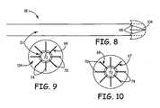
- lead 18comprises lead body 21, conductor 54, electrode 66, and occlusion fabric 104.
- electrode 66provides a cambered fabric support 70 comprising a center portion 72 and legs 74, which extend out from center portion 72 in a cambered fashion. This cambered form allows occlusion fabric 104 to take the shape of a collapsible canopy, which assists in occluding the puncture in the heart wall created by catheter 108. It's helpful if electrode 66 is made of a flexible, strong, and electrically conductive material such as MP35N.
- FIG. 9shows a unipolar configuration where electrode 66 has a single polarity.
- Figure 10shows a bipolar lead configuration where electrodes 67 and 68 have opposite polarities or one of the two is used to sense electrical activity. Electrode 67 and 68 still provide a cambered fabric support 70 comprising a center portion 76 and legs 78.
- electrode 80provides a cambered fabric support 82 comprising a center portion 84 and legs 86, which extend out from center portion 84 in a cambered fashion.
- occlusion fabric 104has a leaflet shape.
- Figure 12shows a unipolar configuration where electrode 80 has a single polarity.
- Figure 13shows a bipolar lead configuration where electrodes 88 and 90 have opposite polarities or one of the two is used to sense electrical activity. Electrode 88 and 90 still provide a cambered fabric support 82 comprising a center portion 92 and legs 94.
- a pacing lead during insertion and implantationas well as a method for pacing in an embodiment of the present teachings is shown.
- catheter 108is used to create a hole 200 through ventricular walls 100 or 102 (step 300).
- catheter 108reaches the left ventricle 107 (step 302) the clinician would push lead 18 through catheter 108 into left ventricle 107 (step 304) and remove catheter 108.
- Cambered support structure 70then expands in an collapsible canopy shape.
- Lead 18can then be retracted (step 306) so that cambered support structure 70 further expands as shown in Figure 15 to seal off hole 200.
- tines 202which are covered by fabric 104 during insertion, pop out when the collapsible canopy unfolds and allow the clinician to retract lead 18 to back electrode 66 against inner wall 100 or 102, but prevent the clinician from pushing the electrode back into the ventricle again thus anchoring lead 18. It is further contemplated tines 202 could be connected to a conductor to act as an electrode thus providing bipolar pacing. After lead 18 is implanted pacemaker 10 could then detect any heart abnormalities and provide a pacing therapy if necessary (state 308).
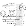
- a pacing lead during insertion and implantation in an embodiment of the present teachingsis shown.
- Lead 18is formed with a serrated edge 212 to provide another anchoring structure.
- a fixation ring 220/222can be slid down over lead 18 to serrated edge 212.
- Fixation ring 220/222is then slid over serrated edge 212 until it abuts right ventricle wall 230.
- Fixation rings 220/222can be pushed towards the distal end of lead 18; however, serrated edge 212 prevents fixation rings 220/222 from being pulled back towards the proximal end of lead 18. Therefore, fixation rings 220/222 in combination with serrated edge 212 act similar to a tie strap in that fixation rings 220/222 lock in place to prevent lead 18 from being pushed into left ventricle 107. Over time scar tissue would grow over occlusion fabric 104 thus assisting in holding fabric 104 over hole 200. Additionally, fixation ring 222 has eyelets 224 which allow for a clinician to suture fixation ring to heart 12 when using a trans-myocardial implantation approach.
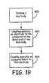
- lead 18can have a lead body 21 formed of an electrically insulative outer sheath 50 of biocompatible material such as a suitable polyurethane or silastic compound (step 400).
- Lead body 21protects electrical conductor 54 disposed within lead body 21 from the corrosive effects presented by body fluids.
- Conductor 54is mechanically and electrically connected to electrode 66 (step 402).
- Operably coupled to electrode 66is an occlusion fabric 104 (step 404).
- Occlusion fabric 104could be attached to electrode 66 in a plurality of ways, such as stitching fabric 104 to electrode 66 or fabric 104 could have pockets to receive the electrode 66.
- Lead body 500is formed of a biocompatible material such as silicon rubber or polyurethane.
- Lead body 500can have electrodes 502 and 504, which can be operably coupled to electrode 506 and 508 respectively.
- Electrodes 506 and 508could be formed of a flexible, elastically deformable material such as near-stoichiometric nickel/titanium alloy, commonly referred to as Nitinol or NiTi. Such superelastic materials may be elastically deformed to a much greater extent than most other materials, yet substantially fully recover their original shape when released.
- Electrodes 506 and 508This permits electrodes 506 and 508 to be deformed sufficiently for insertion into, and passage through, a small-diameter catheter yet automatically elastically returns to its initial shape upon exiting the catheter.
- a strip of insulation 510is placed between electrodes 506 and 508 and acts to electrically separate electrodes 506 and 508, but insulation 510 also acts to occlude hole 200 during implantation of lead 501.
- Insulation 510can be made of most any insulative material such as Dacron and, like electrodes 506 and 508, is relatively elastic so it can be compressed when within a catheter and yet fully expand when removed from the catheter during installation.
Landscapes
- Health & Medical Sciences (AREA)
- Heart & Thoracic Surgery (AREA)
- Cardiology (AREA)
- Animal Behavior & Ethology (AREA)
- Engineering & Computer Science (AREA)
- Biomedical Technology (AREA)
- Nuclear Medicine, Radiotherapy & Molecular Imaging (AREA)
- Radiology & Medical Imaging (AREA)
- Life Sciences & Earth Sciences (AREA)
- General Health & Medical Sciences (AREA)
- Public Health (AREA)
- Veterinary Medicine (AREA)
- Vascular Medicine (AREA)
- Electrotherapy Devices (AREA)
Abstract
Description
- The present teaching relates to an implantable apparatus for treating cardiac arrhythmia, particularly ventricular fibrillation. More particularly, the present teachings relate to an implantable apparatus for cardiac resynchronization therapy to heart failure patients.
- Various types of pacing leads have been developed for endocardial implant, typically in the right ventricle (RV) or right atrial appendage, as well as the coronary sinus. These flexible leads usually are constructed having an outer polymeric sheath encasing one or more electrical conductors. One conductor is typically attached at its distal tip to the shank portion of a tip electrode. In bipolar or multipolar leads, one or more further conductors are provided in coaxial or co-linear relation to the first conductor and is connected at its distal end to a more proximally located, ring-shaped electrode situated along the lead body. The proximal ends of each conductor are coupled to a connector, which includes a single pin in unipolar leads, and additional pins or in-line rings in bipolar and multipolar leads.
US 2003/0199962 andUS 2004/0230283 disclose an implantable medical lead with fixation means to anchor the lead in place. US 5 336 252 discloses an implantable medical electrical lead according to the preamble of claim 1.- Stimulation in both single chamber and dual chamber pacemakers with ventricular stimulation normally takes place in the apex of the RV. A conventional pacemaker of this type typically requires two electrodes. One of these electrodes is placed in the right atrium (RA) and the other in the apex of the RV. The electrodes sense electrical activity in the heart and provide stimulation pulses as needed to rectify arrhythmias.
- Further, while stimulation in the apex has proved clinically effective, there is a need to limit RV pacing to more closely simulate the natural cardiac system.
- In a healthy heart, electrical potential originates in the sinoatrial (SA) node, travels to the atrioventricular (AV) node, and finally to the myocardial mass through the Purkinge fibers. This provides a sequential activation of the atria and the ventricles. Specifically, the sequential polarization and depolarization of the atria and the ventricle results in a naturally synchronized sinus rhythm.
- There is increasing evidence that the sequence of electrical activation is necessary for the normal functioning of the heart. Presently there are three major characteristics of proper electrical activation of a heart: (1) left ventricle (LV) activation before RV activation, (2) in the LV, endocardial activation before epicardial activation, and (3) in both the RV and LV, apex activation before base activation. The earliest electrical activation typically occurs at the endocardium of the lower left side of the septum and the lower anterior wall.
- Recent experiments have shown that creation of an activation sequence similar to that of the natural contraction of the heart contributed to better heart functioning. Patients with poor atrio-ventricular conduction (AV-block) or poor sinus-node function typically receive a ventricular pacemaker. Such pacemaker restores the normal heart operation. However, the traditional position of the ventricular lead is the right ventricular apex. This pacing location may not provide optimal heart functioning and may result in ventricular remodeling.
- Further, use of ventricular pacing is to resynchronize the ventricular activation. This is mainly used in patients with heart failure (HF) who also have left bundle branch block (LBBB). LBBB causes a sequence of activation similar to that during RV apex pacing. In the LBBB patients, left ventricular (LV) or biventricular pacing (BiV) is used to resynchronize ventricular activation, with good results.
- Although LV pacing sites may offer great advantages over RV pacing sites, positioning of the leads is cumbersome. For example, thoracotomy is used to position a lead at the LV wall, but this invasive procedure does not offer significant advantages over the transvenous approach. In the transvenous approach, LV pacing leads are positioned in coronary veins, which can be difficult, time consuming, and not reliable because of lead displacement. Moreover, even if the lead can be positioned in a coronary vein, individual heart anatomies differ widely, such that the preferred site could be difficult to locate for lead replacement.
- Recently a trans-atrial septal approach was introduced to enable LV endocardial pacing. In this approach the pacing lead is advanced from the right atrium through the right atrial septum wall into the left atrium and through the mitral valve into the LV cavity until a proper site at the LV endocardium is reached. A disadvantage with this approach is that a large part of the lead is permanently inside of the LV cavity. One of the many clinical concerns with the trans-atrial septal approach is Emboli originating from this lead may enter the systemic circulation giving rise to strokes.
- The invention provides a medical electrical lead as defined in claim 1.
- Preferably, the lead system includes attachment means into the transventricular system to attach to a location in the LV. The lead system is introduced from the RV side and enables a more reliable site selection in the LV and provides a secure semi-exogenous lead attachment to the LV.
Figure 1 shows a schematic view of the general environment of implantable medical device ("IMD");Figure 2 shows a right perspective view of an embodiment of the pacing lead assembly for the present teachings;Figure 3 shows a side view of an embodiment of a lead body in an embodiment of the present teachings;Figure 4 shows an enlarged axial cross-sectional view of a distal end of a lead body in an embodiment of the present teachings;Figure 5 shows a trans-septal pacing approach using a pacing lead in an embodiment of the present teachings;Figure 6 shows a trans-myocardial pacing approach using a pacing lead in an embodiment of the present teachings;Figure 7 shows a heart wall penetration system for delivery of a pacing lead in an embodiment of the present teachings;Figure 8 shows a side profile of a pacing lead in an embodiment of the present teachings;Figure 9 shows a distal end profile of the pacing lead ofFigure 8 in a unipolar embodiment of the present teachings;Figure 10 shows a distal end profile of the pacing lead ofFigure 8 in a bipolar embodiment of the present teachings;Figure 11 shows a side profile of a pacing lead in an embodiment of the present teachings;Figure 12 shows a distal end profile of the pacing lead ofFigure 11 in a unipolar embodiment of the present teachings;Figure 13 shows a distal end profile of the pacing lead ofFigure 11 in a bipolar embodiment of the present teachings;Figure 14 shows a pacing lead during insertion in an embodiment of the present teachings;Figure 15 shows a pacing lead after insertion in an embodiment of the present teachings;Figure 16 shows a flowchart diagram of a method for pacing a heart in an embodiment of the present teachings;Figure 17 shows a pacing lead during insertion in an embodiment of the present teachings;Figure 18 shows a pacing lead after insertion in an embodiment of the present teachings;Figure 19 shows a flowchart diagram of a method of manufacturing a pacing lead in an embodiment of the present teachings;Figure 20 shows a pacing lead in an embodiment of the present teachings.- The following discussion is presented to enable a person skilled in the art to make and use the present teachings.
- The following detailed description is to be read with reference to the figures, in which like elements in different figures have like reference numerals. The figures, which are not necessarily to scale, depict selected embodiments and are not intended to limit the scope of the present teachings.
- With respect to
Figure 1 , a schematic view of the general environment of implantable medical device ("IMD") is shown.IMD 10 shown inFIG. 1 is a pacemaker comprising at least one of pacing and sensing leads 14, 22, 30, and 40 attached to hermetically sealedenclosure 11 and implanted near human ormammalian heart 12. Pacing and sensing leads 14, 22, 30, and 40 sense electrical signals attendant to the depolarization and re-polarization ofheart 12, and further provide pacing pulses for causing depolarization of cardiac tissue in the vicinity of the distal ends thereof. Leads 14, 22, 30, and 40 may have unipolar or bipolar electrodes disposed thereon, as is well known in the art. Examples ofIMD 10 include implantable cardiac pacemakers disclosed inU.S. Pat. No. 5,158,078 to Bennett et al .,U.S. Pat. No. 5,312,453 to Shelton et al . orU.S. Pat. No. 5,144,949 to Olson . - With reference to
Figure 2 , a right perspective view of an embodiment of a lead assembly utilizing catheter insertion is shown.Lead assembly 18 comprisesguide catheter 20 andlead body 21. Leadbody 21 is received by and fits slidingly withinguide catheter 20.Hub 24 is located at the proximal end ofguide catheter 20.Hemostasis valve 26 may be attached to the proximal end ofhub 24. Removal of sealingcap 28 fromneck 31 permits the introduction of saline solution, anticoagulants, and intravenously administered drugs throughvalve 26. The proximal end ofvalve 26 receiveslead body 21 and guides it throughhub 24 intoguide catheter 20. - With reference to
Figure 3 , a side view of the lead body in an embodiment of an implantable lead body for the present teachings is shown. Leadbody 21 has aproximal end 36 with a conductor 54 (Figure 4 ) for establishing electrical connection betweenlead assembly 18, anIMD 10, and the tissue ofheart 12. Electrically insulativeouter sheath 50 is formed of biocompatible material such as a suitable polyurethane or silastic compound, and protectselectrical conductor 54 disposed withinlead body 21 from the corrosive effects presented by body fluids.Sheath 50 additionally preventsconductor 54 disposed withinlead body 21 from shorting to the body. It is fully contemplated there can be more than one connector, as is discussed below. - With reference to
Figure 4 , an enlarged axial cross-sectional view of lead body distal end in an embodiment of the present teachings is shown.Conductor 54 can be three strands of left-hand-wound twisted MP35-N wire, and can be capable of reliably conducting electrical current after having been subjected to numerous, repeated bending and torquing stresses. However,conductor 54 may comprise a single wire formed of a nickel-titanium alloy such as nitinol. Leadbody 21 has a diameter of about 3 French in some embodiments, but may have a diameter as great as about 4 French or as small as about 2 French.Conductor 54 is mechanically and electrically connected toelectrode 66.Conductor 54 andelectrode 66 can be connected by laser welding however other methods of connection are contemplated. Operably coupled toelectrode 66 is anocclusion fabric 104.Occlusion fabric 104 can be made of most any type of material as long as the material can be implanted within the body. For example,occlusion fabric 104 could be made of Dacron. Further,occlusion fabric 104 could be attached toelectrode 66 in a plurality of ways, such asstitching fabric 104 toelectrode 66 orfabric 104 could have pockets to receive theelectrode 66. Regardless of howelectrode 66 is coupled tofabric 104, it is beneficial for portions of the surface ofelectrode 66 to be exposed to provide good electrical conductivity toheart 12. - With reference to
Figure 5 , a trans-septal pacing approach using a pacing lead in an embodiment of the present teachings is shown. The present teaching discloses positioning a pacing lead inheart 12 atseptum 100 or atmyocardial wall 102. In a trans-septal pacing approach, a standard transvenous entrance is used to advancelead 18 towardsventricular septum 100. The same transvenous entrance would be used to advance apacing lead 19 to the base ofright ventricle 106 to pace the right ventricle as is know in the art. From there lead 18 penetrates ventricularseptum 100 until the lead protrudes into the LV cavity. Then lead 18 is withdrawn, untilelectrode 66 is against the leftseptal endocardium 100 andocclusion fabric 104 operably coupled toelectrode 66 rests against the left septal endocardium blocking the hole created during penetration ofventricular septum 100 bylead 18. This arrangement places the lead in an embedded position in the transventricular system, which enables sensing, detection, and pacing in the LV. As mentioned above, the lower part of the LV septum is substantially the general location where activation starts in the normal heartbeat. With trans-septal pacing the electrical impulse will presumably spread from the septal apex to the base, from endocardium to epicardium and cause the LV side of the septum to be activated before the RV. Therefore, trans-septal pacing combines a relatively easy implantation procedure with minimal risk for formation of emboli and with a sequence of activation similar to the normal activation pattern. The latter will result in optimal LV ejection fraction and minimized remodeling as compared to RV apex pacing. - With reference to
Figure 6 , a trans-myocardial pacing approach using a pacing lead in an embodiment of the present teachings is shown. In a trans-myocardial pacing approach, a standard surgical procedure is used to advancelead 18 towards ventricularmyocardial wall 102. From there lead 18 penetratesventricular wall 102 until the lead enters the LV cavity. Then lead 18 is withdrawn, untilelectrode 66 is against the left septal endocardium and anocclusion fabric 104 operably coupled toelectrode 66 rests against the left septal endocardium blocking the puncture created during penetration of the ventricular septum bylead 18. - With reference to
Figure 7 , a heart wall penetration system for delivery of a pacing lead in an embodiment of the present teachings is shown. Penetration ofseptum 100 orheart wall 102 could be accomplished in a plurality of ways; however, for the purpose of the disclosure penetration will be discussed with respect to a catheter. A stiff,curved guide catheter 108 can be positioned intoright ventricle 106 or close toventricular wall 102. Through catheter 108 a force can be applied to penetrateventricular septum 100 orventricular wall 102. As discussed above, however, penetration ofseptum 100 orheart wall 102 can be accomplished in a plurality of ways such as by advancing a sharp steel wire, thus creating a hole, then withdrawing the wire and introducing the pacing lead through the hole, with a pacing lead having a sharp tip, or by placing a stiffening stylet in a pacing lead that makes the lead stiff enough to penetrate the heart wall. - Pacing the right ventricle maintains normal ventricular activation in case of AV-block or sick sinus syndrome. In these patients cardiac function can be better maintained and remodeling of the heart is likely prevented or reduced. Moreover, since the right ventricular pacing site is likely distal to the block in the case of Left Branch Bundle Block (LBBB), right ventricle pacing may also be used for resynchronization therapy in heart failure LBBB pacing, instead of the coronary venous approach.
- With reference to
Figure 8 , a side profile of a pacing lead in an embodiment of the present teachings is shown. As discussed above, lead 18 compriseslead body 21,conductor 54,electrode 66, andocclusion fabric 104. InFigure 9 ,electrode 66 provides acambered fabric support 70 comprising acenter portion 72 andlegs 74, which extend out fromcenter portion 72 in a cambered fashion. This cambered form allowsocclusion fabric 104 to take the shape of a collapsible canopy, which assists in occluding the puncture in the heart wall created bycatheter 108. It's helpful ifelectrode 66 is made of a flexible, strong, and electrically conductive material such as MP35N. This allowslegs 74 to be compressed againstbody 21 when inside of theinsertion catheter 108, expand to its cambered form upon exitingcatheter 108, and expand further outward whenelectrode 66 is pulled back towards the left ventricular wall as will be discussed in more detail below.Figure 9 shows a unipolar configuration whereelectrode 66 has a single polarity.Figure 10 shows a bipolar lead configuration whereelectrodes Electrode cambered fabric support 70 comprising a center portion 76 andlegs 78. - With reference to
Figure 11 , a side profile of a pacing lead in an embodiment of the present teachings is shown. InFigure 12 ,electrode 80 provides acambered fabric support 82 comprising acenter portion 84 andlegs 86, which extend out fromcenter portion 84 in a cambered fashion. In this embodiment,occlusion fabric 104 has a leaflet shape.Figure 12 shows a unipolar configuration whereelectrode 80 has a single polarity.Figure 13 shows a bipolar lead configuration whereelectrodes Electrode cambered fabric support 82 comprising a center portion 92 andlegs 94. - With reference to
Figures 14-16 , a pacing lead during insertion and implantation as well as a method for pacing in an embodiment of the present teachings is shown. As discussed above, duringinsertion catheter 108 is used to create ahole 200 throughventricular walls 100 or 102 (step 300). Oncecatheter 108 reaches the left ventricle 107 (step 302) the clinician would push lead 18 throughcatheter 108 into left ventricle 107 (step 304) and removecatheter 108.Cambered support structure 70 then expands in an collapsible canopy shape.Lead 18 can then be retracted (step 306) so thatcambered support structure 70 further expands as shown inFigure 15 to seal offhole 200. This retraction action also causeselectrode inner portion 210 ofventricular wall occlusion fabric 104 thus assisting in holdingfabric 104 overhole 200. Additionally,tines 202, which are covered byfabric 104 during insertion, pop out when the collapsible canopy unfolds and allow the clinician to retractlead 18 to backelectrode 66 againstinner wall lead 18. It is further contemplatedtines 202 could be connected to a conductor to act as an electrode thus providing bipolar pacing. Afterlead 18 is implantedpacemaker 10 could then detect any heart abnormalities and provide a pacing therapy if necessary (state 308). - With reference to
Figures 17 and 18 , a pacing lead during insertion and implantation in an embodiment of the present teachings is shown.Lead 18 is formed with a serrated edge 212 to provide another anchoring structure. After insertion ofcatheter 108 and retraction oflead 18 causingelectrode inner portion 210 ofventricular wall lead 18 to serrated edge 212. Fixation ring 220/222 is then slid over serrated edge 212 until it abutsright ventricle wall 230. Fixation rings 220/222 can be pushed towards the distal end oflead 18; however, serrated edge 212 prevents fixation rings 220/222 from being pulled back towards the proximal end oflead 18. Therefore, fixation rings 220/222 in combination with serrated edge 212 act similar to a tie strap in that fixation rings 220/222 lock in place to prevent lead 18 from being pushed intoleft ventricle 107. Over time scar tissue would grow overocclusion fabric 104 thus assisting in holdingfabric 104 overhole 200. Additionally, fixation ring 222 haseyelets 224 which allow for a clinician to suture fixation ring toheart 12 when using a trans-myocardial implantation approach. - With reference to
Figure 19 , a flowchart diagram of a method of manufacturing a pacing lead in an embodiment of the present teachings is shown. As discussed above, lead 18 can have alead body 21 formed of an electrically insulativeouter sheath 50 of biocompatible material such as a suitable polyurethane or silastic compound (step 400). Leadbody 21 protectselectrical conductor 54 disposed withinlead body 21 from the corrosive effects presented by body fluids.Conductor 54 is mechanically and electrically connected to electrode 66 (step 402). Operably coupled toelectrode 66 is an occlusion fabric 104 (step 404).Occlusion fabric 104 could be attached toelectrode 66 in a plurality of ways, such asstitching fabric 104 toelectrode 66 orfabric 104 could have pockets to receive theelectrode 66. - With reference to
Figure 20 , a pacing lead in an embodiment of the present teachings is shown.Lead body 500 is formed of a biocompatible material such as silicon rubber or polyurethane.Lead body 500 can haveelectrodes electrode Electrodes electrodes insulation 510 is placed betweenelectrodes separate electrodes insulation 510 also acts to occludehole 200 during implantation oflead 501.Insulation 510 can be made of most any insulative material such as Dacron and, likeelectrodes - Thus, embodiments of the Trans-Septal/Trans-myocardial Ventricular Pacing Lead are disclosed.
- The disclosed embodiments are presented for purposes of illustration and not limitation, and the present teachings are limited only by the claims that follow.
Claims (11)
- A medical electrical lead for insertion into the heart, comprising:a lead body (21) having a proximal end and a distal end;a conductor (54) traversing from the proximal end to the distal end;an electrode (66) disposed at the distal end of the lead body and electrically coupled to the conductor adapted to electrically stimulate a heart; andocclusion fabric (104) disposed at the distal end of the lead body and supported by the electrode in a shape and configuration adapted to cover puncture in the heart caused by insertion of the lead;characterised in thatthe electrode provides a cambered fabric support structure (70) for the occlusion fabric, wherein the electrode has a center portion (72) with legs (74) extending outward in a cambered fashion.
- The lead of claim 1, further comprising a second electrode adapted to provide bipolar electrical stimulation of the heart.
- The lead of claim 1, wherein the occlusion fabric is an electrically insulative material.
- The lead of claim 1, wherein the occlusion fabric operably couples the cambered fabric support structure comprises a collapsible canopy.
- The lead of claim 1, wherein the occlusion fabric is operably coupled to the cambered fabric support structure is in the shape of leaflets.
- The medical electrical lead of any preceding claim, wherein the electrode (66) extends radially outward from the lead body and is flexible; and wherein
the occlusion fabric is flexible, the flexibility permitting the occlusion fabric and the electrode to conform to a surface of the heart to cap punctures in the heart. - The lead of claim 6, further comprising a tine (202) that is covered by the cambered fabric support structure during implantation of the medical lead.
- The lead of claim 7, wherein the tine is configured to be exposed after insertion of the distal end into the left ventricle, the tine being oriented to allow withdrawal of the distal end from the left ventricle and prevent further movement of the distal end into the left ventricle.
- The lead of claim 6, wherein the distal end can be inserted into the left ventricle with a catheter or a trans-septal bore needle.
- The lead of claim 6, wherein the distal end has a saw-tooth shaped surface (212).
- The lead of claim 10, further comprising a fixation ring (220, 222) that can be pushed over the saw tooth surface wherein the fixation ring cannot be retracted and the distal end of the lead cannot be pushed further into the left ventricle.
Applications Claiming Priority (2)
| Application Number | Priority Date | Filing Date | Title |
|---|---|---|---|
| US11/096,510US7321798B2 (en) | 2005-03-31 | 2005-03-31 | Trans-septal/trans-myocardial ventricular pacing lead |
| PCT/US2006/011899WO2006105395A2 (en) | 2005-03-31 | 2006-03-30 | Trans-septal/trans-myocardial ventricular pacing lead |
Publications (2)
| Publication Number | Publication Date |
|---|---|
| EP1885435A2 EP1885435A2 (en) | 2008-02-13 |
| EP1885435B1true EP1885435B1 (en) | 2011-05-04 |
Family
ID=36950049
Family Applications (1)
| Application Number | Title | Priority Date | Filing Date |
|---|---|---|---|
| EP06740193ANot-in-forceEP1885435B1 (en) | 2005-03-31 | 2006-03-30 | Trans-septal/trans-myocardial ventricular pacing lead |
Country Status (7)
| Country | Link |
|---|---|
| US (1) | US7321798B2 (en) |
| EP (1) | EP1885435B1 (en) |
| JP (1) | JP4850899B2 (en) |
| AT (1) | ATE507870T1 (en) |
| CA (1) | CA2600413A1 (en) |
| DE (1) | DE602006021737D1 (en) |
| WO (1) | WO2006105395A2 (en) |
Families Citing this family (95)
| Publication number | Priority date | Publication date | Assignee | Title |
|---|---|---|---|---|
| US8326423B2 (en) | 2004-12-20 | 2012-12-04 | Cardiac Pacemakers, Inc. | Devices and methods for steering electrical stimulation in cardiac rhythm management |
| US8010192B2 (en)* | 2004-12-20 | 2011-08-30 | Cardiac Pacemakers, Inc. | Endocardial pacing relating to conduction abnormalities |
| US8014861B2 (en)* | 2004-12-20 | 2011-09-06 | Cardiac Pacemakers, Inc. | Systems, devices and methods relating to endocardial pacing for resynchronization |
| US8010191B2 (en) | 2004-12-20 | 2011-08-30 | Cardiac Pacemakers, Inc. | Systems, devices and methods for monitoring efficiency of pacing |
| US8290586B2 (en)* | 2004-12-20 | 2012-10-16 | Cardiac Pacemakers, Inc. | Methods, devices and systems for single-chamber pacing using a dual-chamber pacing device |
| US8005544B2 (en) | 2004-12-20 | 2011-08-23 | Cardiac Pacemakers, Inc. | Endocardial pacing devices and methods useful for resynchronization and defibrillation |
| US8423139B2 (en) | 2004-12-20 | 2013-04-16 | Cardiac Pacemakers, Inc. | Methods, devices and systems for cardiac rhythm management using an electrode arrangement |
| AR047851A1 (en) | 2004-12-20 | 2006-03-01 | Giniger Alberto German | A NEW MARCAPASOS THAT RESTORES OR PRESERVES THE PHYSIOLOGICAL ELECTRIC DRIVING OF THE HEART AND A METHOD OF APPLICATION |
| US8050756B2 (en) | 2004-12-20 | 2011-11-01 | Cardiac Pacemakers, Inc. | Circuit-based devices and methods for pulse control of endocardial pacing in cardiac rhythm management |
| US7899550B1 (en)* | 2006-08-21 | 2011-03-01 | Pacesetter, Inc. | Apparatus and method for transseptal fixation |
| US20080294229A1 (en)* | 2006-10-17 | 2008-11-27 | Friedman Paul A | Helical Electrodes for Intramyocardial Pacing and Sensing |
| WO2008058265A2 (en)* | 2006-11-08 | 2008-05-15 | Emerge Medsystems Llc | Transmuscular left ventricular cardiac stimulation leads and related systems and methods |
| WO2009006325A1 (en)* | 2007-06-29 | 2009-01-08 | Action Medical, Inc. | Devices and methods for steering electrical stimulation in cardiac rhythm management |
| DE102008040304A1 (en) | 2008-07-10 | 2010-01-14 | Biotronik Crm Patent Ag | Implantable electrode lead or electrode lead assembly |
| CA2732309C (en) | 2008-07-30 | 2018-04-10 | Ecole Polytechnique Federale De Lausanne (Epfl) | Apparatus and method for optimized stimulation of a neurological target |
| US9750592B2 (en)* | 2008-10-10 | 2017-09-05 | Carsten Nils Gutt | Arrangement for implanting and method for implanting |
| JP5667987B2 (en) | 2008-11-12 | 2015-02-12 | エコーレ ポリテクニーク フェデラーレ デ ローザンヌ (イーピーエフエル) | Micromachined nerve stimulation device |
| WO2010071849A2 (en) | 2008-12-19 | 2010-06-24 | Action Medical, Inc. | Devices, methods, and systems including cardiac pacing |
| DE102009030340B4 (en)* | 2009-06-25 | 2011-12-01 | Peter Osypka | Electrode arrangement with a stimulation electrode for the left ventricle |
| US8406896B2 (en)* | 2009-06-29 | 2013-03-26 | Boston Scientific Neuromodulation Corporation | Multi-element contact assemblies for electrical stimulation systems and systems and methods of making and using |
| EP2453807A4 (en)* | 2009-07-17 | 2017-06-21 | Richard B. North | Shaped electrode and dissecting tool |
| US9072890B2 (en) | 2009-09-03 | 2015-07-07 | Mayo Foundation For Medical Education And Research | Pacing, sensing or defibrillator leads for implantation into the myocardium |
| CA2782710C (en) | 2009-12-01 | 2019-01-22 | Ecole Polytechnique Federale De Lausanne | Microfabricated neurostimulation device and methods of making and using the same |
| CA2795159C (en) | 2010-04-01 | 2020-11-03 | Ecole Polytechnique Federale De Lausanne | Device for interacting with neurological tissue and methods of making and using the same |
| WO2011139691A1 (en) | 2010-04-27 | 2011-11-10 | Cardiac Pacemakers, Inc. | His-bundle capture verification and monitoring |
| US9072872B2 (en) | 2010-10-29 | 2015-07-07 | Medtronic, Inc. | Telescoping catheter delivery system for left heart endocardial device placement |
| US8942829B2 (en) | 2011-01-20 | 2015-01-27 | Medtronic, Inc. | Trans-septal lead anchoring |
| US11311718B2 (en) | 2014-05-16 | 2022-04-26 | Aleva Neurotherapeutics Sa | Device for interacting with neurological tissue and methods of making and using the same |
| WO2015173787A1 (en) | 2014-05-16 | 2015-11-19 | Aleva Neurotherapeutics Sa | Device for interacting with neurological tissue and methods of making and using the same |
| US9403011B2 (en) | 2014-08-27 | 2016-08-02 | Aleva Neurotherapeutics | Leadless neurostimulator |
| US9474894B2 (en) | 2014-08-27 | 2016-10-25 | Aleva Neurotherapeutics | Deep brain stimulation lead |
| US9925376B2 (en) | 2014-08-27 | 2018-03-27 | Aleva Neurotherapeutics | Treatment of autoimmune diseases with deep brain stimulation |
| US10905886B2 (en) | 2015-12-28 | 2021-02-02 | Cardiac Pacemakers, Inc. | Implantable medical device for deployment across the atrioventricular septum |
| US10668294B2 (en) | 2016-05-10 | 2020-06-02 | Cardiac Pacemakers, Inc. | Leadless cardiac pacemaker configured for over the wire delivery |
| US11207527B2 (en) | 2016-07-06 | 2021-12-28 | Cardiac Pacemakers, Inc. | Method and system for determining an atrial contraction timing fiducial in a leadless cardiac pacemaker system |
| EP3487579B1 (en) | 2016-07-20 | 2020-11-25 | Cardiac Pacemakers, Inc. | System for utilizing an atrial contraction timing fiducial in a leadless cardiac pacemaker system |
| WO2018035343A1 (en) | 2016-08-19 | 2018-02-22 | Cardiac Pacemakers, Inc. | Trans septal implantable medical device |
| US10994145B2 (en) | 2016-09-21 | 2021-05-04 | Cardiac Pacemakers, Inc. | Implantable cardiac monitor |
| CN109803720B (en) | 2016-09-21 | 2023-08-15 | 心脏起搏器股份公司 | Leadless stimulation device having a housing containing its internal components and functioning as a terminal for a battery case and an internal battery |
| US10758737B2 (en) | 2016-09-21 | 2020-09-01 | Cardiac Pacemakers, Inc. | Using sensor data from an intracardially implanted medical device to influence operation of an extracardially implantable cardioverter |
| US10413733B2 (en) | 2016-10-27 | 2019-09-17 | Cardiac Pacemakers, Inc. | Implantable medical device with gyroscope |
| EP3532161B1 (en) | 2016-10-27 | 2023-08-30 | Cardiac Pacemakers, Inc. | Implantable medical device with pressure sensor |
| US10561330B2 (en) | 2016-10-27 | 2020-02-18 | Cardiac Pacemakers, Inc. | Implantable medical device having a sense channel with performance adjustment |
| US10434314B2 (en) | 2016-10-27 | 2019-10-08 | Cardiac Pacemakers, Inc. | Use of a separate device in managing the pace pulse energy of a cardiac pacemaker |
| CN109922860B (en) | 2016-10-27 | 2023-07-04 | 心脏起搏器股份公司 | Implantable medical device delivery system with integrated sensor |
| EP3532157B1 (en) | 2016-10-31 | 2020-08-26 | Cardiac Pacemakers, Inc. | Systems for activity level pacing |
| US10434317B2 (en) | 2016-10-31 | 2019-10-08 | Cardiac Pacemakers, Inc. | Systems and methods for activity level pacing |
| WO2018089311A1 (en) | 2016-11-08 | 2018-05-17 | Cardiac Pacemakers, Inc | Implantable medical device for atrial deployment |
| WO2018089308A1 (en) | 2016-11-09 | 2018-05-17 | Cardiac Pacemakers, Inc. | Systems, devices, and methods for setting cardiac pacing pulse parameters for a cardiac pacing device |
| CN110114114B (en) | 2016-12-27 | 2023-05-02 | 心脏起搏器股份公司 | Delivery devices and methods for leadless cardiac devices |
| AU2017387024B2 (en) | 2016-12-27 | 2020-04-09 | Cardiac Pacemakers, Inc. | Leadless delivery catheter with conductive pathway |
| US10806931B2 (en) | 2016-12-27 | 2020-10-20 | Cardiac Pacemakers, Inc. | Delivery devices and methods for leadless cardiac devices |
| US10485981B2 (en) | 2016-12-27 | 2019-11-26 | Cardiac Pacemakers, Inc. | Fixation methods for leadless cardiac devices |
| WO2018140597A2 (en) | 2017-01-26 | 2018-08-02 | Cardiac Pacemakers, Inc. | Delivery devices and methods for leadless cardiac devices |
| JP7000438B2 (en) | 2017-01-26 | 2022-01-19 | カーディアック ペースメイカーズ, インコーポレイテッド | Human device communication with redundant message transmission |
| CN110198759B (en) | 2017-01-26 | 2023-08-11 | 心脏起搏器股份公司 | Leadless implantable device with removable fasteners |
| CN110418661B (en) | 2017-03-10 | 2024-01-02 | 心脏起搏器股份公司 | Fixing piece for leadless cardiac device |
| US10737092B2 (en) | 2017-03-30 | 2020-08-11 | Cardiac Pacemakers, Inc. | Delivery devices and methods for leadless cardiac devices |
| US10905872B2 (en) | 2017-04-03 | 2021-02-02 | Cardiac Pacemakers, Inc. | Implantable medical device with a movable electrode biased toward an extended position |
| CN110740779B (en) | 2017-04-03 | 2024-03-08 | 心脏起搏器股份公司 | Cardiac pacemaker with pacing pulse energy modulation based on sensed heart rate |
| US11577085B2 (en) | 2017-08-03 | 2023-02-14 | Cardiac Pacemakers, Inc. | Delivery devices and methods for leadless cardiac devices |
| US10918875B2 (en) | 2017-08-18 | 2021-02-16 | Cardiac Pacemakers, Inc. | Implantable medical device with a flux concentrator and a receiving coil disposed about the flux concentrator |
| CN111032148B (en) | 2017-08-18 | 2024-04-02 | 心脏起搏器股份公司 | Implantable medical device with pressure sensor |
| US11235163B2 (en) | 2017-09-20 | 2022-02-01 | Cardiac Pacemakers, Inc. | Implantable medical device with multiple modes of operation |
| US11185703B2 (en) | 2017-11-07 | 2021-11-30 | Cardiac Pacemakers, Inc. | Leadless cardiac pacemaker for bundle of his pacing |
| EP3717059B1 (en) | 2017-12-01 | 2024-11-20 | Cardiac Pacemakers, Inc. | Systems for detecting atrial contraction timing fiducials within a search window from a ventricularly implanted leadless cardiac pacemaker |
| WO2019108830A1 (en) | 2017-12-01 | 2019-06-06 | Cardiac Pacemakers, Inc. | Leadless cardiac pacemaker with reversionary behavior |
| WO2019108482A1 (en) | 2017-12-01 | 2019-06-06 | Cardiac Pacemakers, Inc. | Methods and systems for detecting atrial contraction timing fiducials and determining a cardiac interval from a ventricularly implanted leadless cardiac pacemaker |
| CN111417433B (en) | 2017-12-01 | 2024-04-30 | 心脏起搏器股份公司 | Method and system for detecting atrial contraction timing reference during ventricular filling from a ventricularly implanted leadless cardiac pacemaker |
| WO2019136148A1 (en) | 2018-01-04 | 2019-07-11 | Cardiac Pacemakers, Inc. | Dual chamber pacing without beat-to-beat communication |
| US11529523B2 (en) | 2018-01-04 | 2022-12-20 | Cardiac Pacemakers, Inc. | Handheld bridge device for providing a communication bridge between an implanted medical device and a smartphone |
| US10702692B2 (en) | 2018-03-02 | 2020-07-07 | Aleva Neurotherapeutics | Neurostimulation device |
| JP2021518192A (en) | 2018-03-23 | 2021-08-02 | メドトロニック,インコーポレイテッド | VfA cardiac resynchronization therapy |
| EP3768160B1 (en) | 2018-03-23 | 2023-06-07 | Medtronic, Inc. | Vfa cardiac therapy for tachycardia |
| CN111886046B (en) | 2018-03-23 | 2025-05-27 | 美敦力公司 | AV-synchronized VFA cardiac therapy |
| US11235161B2 (en) | 2018-09-26 | 2022-02-01 | Medtronic, Inc. | Capture in ventricle-from-atrium cardiac therapy |
| US11951313B2 (en) | 2018-11-17 | 2024-04-09 | Medtronic, Inc. | VFA delivery systems and methods |
| US12296177B2 (en) | 2018-12-21 | 2025-05-13 | Medtronic, Inc. | Delivery systems and methods for left ventricular pacing |
| US11679265B2 (en) | 2019-02-14 | 2023-06-20 | Medtronic, Inc. | Lead-in-lead systems and methods for cardiac therapy |
| US11697025B2 (en) | 2019-03-29 | 2023-07-11 | Medtronic, Inc. | Cardiac conduction system capture |
| CN113660977B (en) | 2019-03-29 | 2024-12-17 | 心脏起搏器股份公司 | Systems and methods for treating cardiac arrhythmias |
| EP3946556B1 (en) | 2019-03-29 | 2024-06-19 | Cardiac Pacemakers, Inc. | Systems for treating cardiac arrhythmias |
| US11213676B2 (en) | 2019-04-01 | 2022-01-04 | Medtronic, Inc. | Delivery systems for VfA cardiac therapy |
| US11712188B2 (en) | 2019-05-07 | 2023-08-01 | Medtronic, Inc. | Posterior left bundle branch engagement |
| US11633607B2 (en) | 2019-07-24 | 2023-04-25 | Medtronic, Inc. | AV synchronous septal pacing |
| US11305127B2 (en) | 2019-08-26 | 2022-04-19 | Medtronic Inc. | VfA delivery and implant region detection |
| US11510697B2 (en) | 2019-09-11 | 2022-11-29 | Cardiac Pacemakers, Inc. | Tools and systems for implanting and/or retrieving a leadless cardiac pacing device with helix fixation |
| WO2021050685A1 (en) | 2019-09-11 | 2021-03-18 | Cardiac Pacemakers, Inc. | Tools and systems for implanting and/or retrieving a leadless cardiac pacing device with helix fixation |
| US11813466B2 (en) | 2020-01-27 | 2023-11-14 | Medtronic, Inc. | Atrioventricular nodal stimulation |
| US11975206B2 (en)* | 2020-03-06 | 2024-05-07 | Medtronic, Inc. | Multi-electrode implantable medical device (IMD) |
| US11911168B2 (en) | 2020-04-03 | 2024-02-27 | Medtronic, Inc. | Cardiac conduction system therapy benefit determination |
| US11813464B2 (en) | 2020-07-31 | 2023-11-14 | Medtronic, Inc. | Cardiac conduction system evaluation |
| FR3115212B1 (en)* | 2020-10-15 | 2025-10-03 | Sorin Crm Sas | Set of an implantation accessory and an implantable flexible stimulation probe |
| US12246181B2 (en) | 2021-04-02 | 2025-03-11 | Medtronic, Inc. | Dual chamber pacing |
| US12274842B2 (en) | 2021-06-08 | 2025-04-15 | Medtronic, Inc. | Guide wire system |
Family Cites Families (43)
| Publication number | Priority date | Publication date | Assignee | Title |
|---|---|---|---|---|
| US4946457A (en)* | 1987-12-03 | 1990-08-07 | Dimed, Incorporated | Defibrillator system with cardiac leads and method for transvenous implantation |
| US5158078A (en)* | 1990-08-14 | 1992-10-27 | Medtronic, Inc. | Rate responsive pacemaker and methods for optimizing its operation |
| US5144949A (en)* | 1991-03-15 | 1992-09-08 | Medtronic, Inc. | Dual chamber rate responsive pacemaker with automatic mode switching |
| EP0545091B1 (en)* | 1991-11-05 | 1999-07-07 | The Children's Medical Center Corporation | Occluder for repair of cardiac and vascular defects |
| US5312453A (en)* | 1992-05-11 | 1994-05-17 | Medtronic, Inc. | Rate responsive cardiac pacemaker and method for work-modulating pacing rate deceleration |
| US5336252A (en)* | 1992-06-22 | 1994-08-09 | Cohen Donald M | System and method for implanting cardiac electrical leads |
| US5293869A (en)* | 1992-09-25 | 1994-03-15 | Ep Technologies, Inc. | Cardiac probe with dynamic support for maintaining constant surface contact during heart systole and diastole |
| US5300107A (en)* | 1992-10-22 | 1994-04-05 | Medtronic, Inc. | Universal tined myocardial pacing lead |
| WO1997016119A1 (en)* | 1995-10-30 | 1997-05-09 | Children's Medical Center Corporation | Self-centering umbrella-type septal closure device |
| US5662698A (en)* | 1995-12-06 | 1997-09-02 | Ventritex, Inc. | Nonshunting endocardial defibrillation lead |
| US5728140A (en)* | 1996-06-17 | 1998-03-17 | Cardiac Pacemakers, Inc. | Method for evoking capture of left ventricle using transeptal pacing lead |
| US5741297A (en)* | 1996-08-28 | 1998-04-21 | Simon; Morris | Daisy occluder and method for septal defect repair |
| US6048553A (en)* | 1997-03-17 | 2000-04-11 | Macquarie Veterinary Supplies Pty Ltd | Aqueous metal bicarbonate solution useful in treating inflammatory, degenerative and viral diseases |
| US20010044619A1 (en)* | 1998-04-08 | 2001-11-22 | Peter A. Altman | Cardiac drug delivery system and method for use |
| US6245012B1 (en)* | 1999-03-19 | 2001-06-12 | Nmt Medical, Inc. | Free standing filter |
| US6551344B2 (en)* | 2000-04-26 | 2003-04-22 | Ev3 Inc. | Septal defect occluder |
| US6440152B1 (en)* | 2000-07-28 | 2002-08-27 | Microvena Corporation | Defect occluder release assembly and method |
| US6746404B2 (en)* | 2000-12-18 | 2004-06-08 | Biosense, Inc. | Method for anchoring a medical device between tissue |
| US6535764B2 (en)* | 2001-05-01 | 2003-03-18 | Intrapace, Inc. | Gastric treatment and diagnosis device and method |
| AU2002323634A1 (en)* | 2001-09-06 | 2003-03-24 | Nmt Medical, Inc. | Flexible delivery system |
| US20040230283A1 (en)* | 2001-11-29 | 2004-11-18 | Medtronic, Inc. | Trans-septal pacing method and apparatus |
| US7318833B2 (en)* | 2001-12-19 | 2008-01-15 | Nmt Medical, Inc. | PFO closure device with flexible thrombogenic joint and improved dislodgement resistance |
| EP1471835A4 (en)* | 2002-01-14 | 2008-03-19 | Nmt Medical Inc | Patent foramen ovale (pfo) closure method and device |
| US20030139819A1 (en)* | 2002-01-18 | 2003-07-24 | Beer Nicholas De | Method and apparatus for closing septal defects |
| CA2643221A1 (en)* | 2002-03-15 | 2003-09-25 | Nmt Medical, Inc. | Coupling system useful in placement of implants |
| JP2005521447A (en)* | 2002-03-25 | 2005-07-21 | エヌエムティー メディカル インコーポレイテッド | Closure clip of patent foramen ovale (PFO) |
| US20030199962A1 (en)* | 2002-04-22 | 2003-10-23 | Chester Struble | Anti-slip leads for placement within tissue |
| US7177704B2 (en)* | 2002-04-29 | 2007-02-13 | Medtronic, Inc. | Pacing method and apparatus |
| AU2003240549A1 (en)* | 2002-06-05 | 2003-12-22 | Nmt Medical, Inc. | Patent foramen ovale (pfo) closure device with radial and circumferential support |
| US7840261B2 (en)* | 2002-06-05 | 2010-11-23 | Biocardia, Inc. | Catheter systems and methods for placing bi-ventricular pacing leads |
| AU2003272323A1 (en)* | 2002-09-23 | 2004-04-08 | Nmt Medical, Inc. | Septal puncture device |
| WO2004028348A2 (en)* | 2002-09-26 | 2004-04-08 | Savacor, Inc. | Cardiovascular anchoring device and method of deploying same |
| US7082335B2 (en)* | 2002-09-30 | 2006-07-25 | Medtronic, Inc. | Multipolar pacing method and apparatus |
| US20040127855A1 (en)* | 2002-10-10 | 2004-07-01 | Nmt Medical, Inc. | Hemostasis valve |
| EP1556117A1 (en)* | 2002-10-25 | 2005-07-27 | NMT Medical, Inc. | Expandable sheath tubing |
| US20040093017A1 (en)* | 2002-11-06 | 2004-05-13 | Nmt Medical, Inc. | Medical devices utilizing modified shape memory alloy |
| EP1560525B1 (en)* | 2002-11-07 | 2009-01-14 | NMT Medical, Inc. | Patent foramen ovale (pfo) closure with magnetic force |
| WO2004052213A1 (en)* | 2002-12-09 | 2004-06-24 | Nmt Medical, Inc. | Septal closure devices |
| US7618435B2 (en)* | 2003-03-04 | 2009-11-17 | Nmt Medical, Inc. | Magnetic attachment systems |
| US20040176788A1 (en)* | 2003-03-07 | 2004-09-09 | Nmt Medical, Inc. | Vacuum attachment system |
| US7317951B2 (en)* | 2003-07-25 | 2008-01-08 | Integrated Sensing Systems, Inc. | Anchor for medical implant placement and method of manufacture |
| FR2859912B1 (en)* | 2003-09-22 | 2005-11-18 | Ela Medical Sa | NECESSARY FOR DRILLING THE CARDIAC SEPTUM AND PLACING A TRANSSEPTAL DEVICE, IN PARTICULAR A STIMULATION PROBE OF A LEFT CAVITY |
| US7212869B2 (en)* | 2004-02-04 | 2007-05-01 | Medtronic, Inc. | Lead retention means |
- 2005
- 2005-03-31USUS11/096,510patent/US7321798B2/ennot_activeExpired - Fee Related
- 2006
- 2006-03-30JPJP2008504419Apatent/JP4850899B2/ennot_activeExpired - Fee Related
- 2006-03-30WOPCT/US2006/011899patent/WO2006105395A2/enactiveApplication Filing
- 2006-03-30DEDE602006021737Tpatent/DE602006021737D1/enactiveActive
- 2006-03-30EPEP06740193Apatent/EP1885435B1/ennot_activeNot-in-force
- 2006-03-30ATAT06740193Tpatent/ATE507870T1/ennot_activeIP Right Cessation
- 2006-03-30CACA002600413Apatent/CA2600413A1/ennot_activeAbandoned
Also Published As
| Publication number | Publication date |
|---|---|
| WO2006105395A3 (en) | 2006-11-30 |
| JP4850899B2 (en) | 2012-01-11 |
| WO2006105395A2 (en) | 2006-10-05 |
| US20060224224A1 (en) | 2006-10-05 |
| JP2008534158A (en) | 2008-08-28 |
| CA2600413A1 (en) | 2006-10-05 |
| DE602006021737D1 (en) | 2011-06-16 |
| ATE507870T1 (en) | 2011-05-15 |
| US7321798B2 (en) | 2008-01-22 |
| EP1885435A2 (en) | 2008-02-13 |
Similar Documents
| Publication | Publication Date | Title |
|---|---|---|
| EP1885435B1 (en) | Trans-septal/trans-myocardial ventricular pacing lead | |
| US10835737B2 (en) | Implantable medical device fixation | |
| US7177704B2 (en) | Pacing method and apparatus | |
| US7529584B2 (en) | Pacing method | |
| US5693081A (en) | Endocardial lead system with defibrillation electrode fixation | |
| US7418298B2 (en) | Myocardial lead with fixation mechanism | |
| US4858623A (en) | Active fixation mechanism for lead assembly of an implantable cardiac stimulator | |
| EP1744808B1 (en) | Trans-septal cardiac pacing lead | |
| EP3924032B1 (en) | Lead-in-lead systems for cardiac therapy | |
| US5643338A (en) | Single-pass A-V lead for pacing with stimulation of right ventricular outflow tract | |
| US8942829B2 (en) | Trans-septal lead anchoring | |
| US20150045868A1 (en) | Implantable medical device fixation | |
| US9265937B2 (en) | Implantable indifferent reference electrode pole | |
| EP4628150A2 (en) | Implantable medical device fixation | |
| US7499759B2 (en) | Distal or proximal fixation of over-the-tether myocardial leads | |
| Gunawan et al. | Early Experience of Left Bundle Branch Pacing with Lumenless Lead in a Single Center: A Case Series |
Legal Events
| Date | Code | Title | Description |
|---|---|---|---|
| PUAI | Public reference made under article 153(3) epc to a published international application that has entered the european phase | Free format text:ORIGINAL CODE: 0009012 | |
| 17P | Request for examination filed | Effective date:20071010 | |
| AK | Designated contracting states | Kind code of ref document:A2 Designated state(s):AT BE BG CH CY CZ DE DK EE ES FI FR GB GR HU IE IS IT LI LT LU LV MC NL PL PT RO SE SI SK TR | |
| 17Q | First examination report despatched | Effective date:20080429 | |
| DAX | Request for extension of the european patent (deleted) | ||
| GRAP | Despatch of communication of intention to grant a patent | Free format text:ORIGINAL CODE: EPIDOSNIGR1 | |
| GRAS | Grant fee paid | Free format text:ORIGINAL CODE: EPIDOSNIGR3 | |
| GRAA | (expected) grant | Free format text:ORIGINAL CODE: 0009210 | |
| AK | Designated contracting states | Kind code of ref document:B1 Designated state(s):AT BE BG CH CY CZ DE DK EE ES FI FR GB GR HU IE IS IT LI LT LU LV MC NL PL PT RO SE SI SK TR | |
| REG | Reference to a national code | Ref country code:GB Ref legal event code:FG4D | |
| REG | Reference to a national code | Ref country code:CH Ref legal event code:EP | |
| REG | Reference to a national code | Ref country code:IE Ref legal event code:FG4D | |
| REF | Corresponds to: | Ref document number:602006021737 Country of ref document:DE Date of ref document:20110616 Kind code of ref document:P | |
| REG | Reference to a national code | Ref country code:DE Ref legal event code:R096 Ref document number:602006021737 Country of ref document:DE Effective date:20110616 | |
| REG | Reference to a national code | Ref country code:NL Ref legal event code:VDEP Effective date:20110504 | |
| PG25 | Lapsed in a contracting state [announced via postgrant information from national office to epo] | Ref country code:PT Free format text:LAPSE BECAUSE OF FAILURE TO SUBMIT A TRANSLATION OF THE DESCRIPTION OR TO PAY THE FEE WITHIN THE PRESCRIBED TIME-LIMIT Effective date:20110905 Ref country code:SE Free format text:LAPSE BECAUSE OF FAILURE TO SUBMIT A TRANSLATION OF THE DESCRIPTION OR TO PAY THE FEE WITHIN THE PRESCRIBED TIME-LIMIT Effective date:20110504 Ref country code:LT Free format text:LAPSE BECAUSE OF FAILURE TO SUBMIT A TRANSLATION OF THE DESCRIPTION OR TO PAY THE FEE WITHIN THE PRESCRIBED TIME-LIMIT Effective date:20110504 | |
| PG25 | Lapsed in a contracting state [announced via postgrant information from national office to epo] | Ref country code:GR Free format text:LAPSE BECAUSE OF FAILURE TO SUBMIT A TRANSLATION OF THE DESCRIPTION OR TO PAY THE FEE WITHIN THE PRESCRIBED TIME-LIMIT Effective date:20110805 Ref country code:AT Free format text:LAPSE BECAUSE OF FAILURE TO SUBMIT A TRANSLATION OF THE DESCRIPTION OR TO PAY THE FEE WITHIN THE PRESCRIBED TIME-LIMIT Effective date:20110504 Ref country code:IS Free format text:LAPSE BECAUSE OF FAILURE TO SUBMIT A TRANSLATION OF THE DESCRIPTION OR TO PAY THE FEE WITHIN THE PRESCRIBED TIME-LIMIT Effective date:20110904 Ref country code:CY Free format text:LAPSE BECAUSE OF FAILURE TO SUBMIT A TRANSLATION OF THE DESCRIPTION OR TO PAY THE FEE WITHIN THE PRESCRIBED TIME-LIMIT Effective date:20110504 Ref country code:LV Free format text:LAPSE BECAUSE OF FAILURE TO SUBMIT A TRANSLATION OF THE DESCRIPTION OR TO PAY THE FEE WITHIN THE PRESCRIBED TIME-LIMIT Effective date:20110504 Ref country code:FI Free format text:LAPSE BECAUSE OF FAILURE TO SUBMIT A TRANSLATION OF THE DESCRIPTION OR TO PAY THE FEE WITHIN THE PRESCRIBED TIME-LIMIT Effective date:20110504 Ref country code:ES Free format text:LAPSE BECAUSE OF FAILURE TO SUBMIT A TRANSLATION OF THE DESCRIPTION OR TO PAY THE FEE WITHIN THE PRESCRIBED TIME-LIMIT Effective date:20110815 Ref country code:SI Free format text:LAPSE BECAUSE OF FAILURE TO SUBMIT A TRANSLATION OF THE DESCRIPTION OR TO PAY THE FEE WITHIN THE PRESCRIBED TIME-LIMIT Effective date:20110504 Ref country code:BE Free format text:LAPSE BECAUSE OF FAILURE TO SUBMIT A TRANSLATION OF THE DESCRIPTION OR TO PAY THE FEE WITHIN THE PRESCRIBED TIME-LIMIT Effective date:20110504 | |
| PG25 | Lapsed in a contracting state [announced via postgrant information from national office to epo] | Ref country code:NL Free format text:LAPSE BECAUSE OF FAILURE TO SUBMIT A TRANSLATION OF THE DESCRIPTION OR TO PAY THE FEE WITHIN THE PRESCRIBED TIME-LIMIT Effective date:20110504 | |
| PG25 | Lapsed in a contracting state [announced via postgrant information from national office to epo] | Ref country code:CZ Free format text:LAPSE BECAUSE OF FAILURE TO SUBMIT A TRANSLATION OF THE DESCRIPTION OR TO PAY THE FEE WITHIN THE PRESCRIBED TIME-LIMIT Effective date:20110504 Ref country code:EE Free format text:LAPSE BECAUSE OF FAILURE TO SUBMIT A TRANSLATION OF THE DESCRIPTION OR TO PAY THE FEE WITHIN THE PRESCRIBED TIME-LIMIT Effective date:20110504 | |
| PG25 | Lapsed in a contracting state [announced via postgrant information from national office to epo] | Ref country code:SK Free format text:LAPSE BECAUSE OF FAILURE TO SUBMIT A TRANSLATION OF THE DESCRIPTION OR TO PAY THE FEE WITHIN THE PRESCRIBED TIME-LIMIT Effective date:20110504 Ref country code:PL Free format text:LAPSE BECAUSE OF FAILURE TO SUBMIT A TRANSLATION OF THE DESCRIPTION OR TO PAY THE FEE WITHIN THE PRESCRIBED TIME-LIMIT Effective date:20110504 Ref country code:RO Free format text:LAPSE BECAUSE OF FAILURE TO SUBMIT A TRANSLATION OF THE DESCRIPTION OR TO PAY THE FEE WITHIN THE PRESCRIBED TIME-LIMIT Effective date:20110504 Ref country code:DK Free format text:LAPSE BECAUSE OF FAILURE TO SUBMIT A TRANSLATION OF THE DESCRIPTION OR TO PAY THE FEE WITHIN THE PRESCRIBED TIME-LIMIT Effective date:20110504 | |
| PLBE | No opposition filed within time limit | Free format text:ORIGINAL CODE: 0009261 | |
| STAA | Information on the status of an ep patent application or granted ep patent | Free format text:STATUS: NO OPPOSITION FILED WITHIN TIME LIMIT | |
| 26N | No opposition filed | Effective date:20120207 | |
| PG25 | Lapsed in a contracting state [announced via postgrant information from national office to epo] | Ref country code:IT Free format text:LAPSE BECAUSE OF FAILURE TO SUBMIT A TRANSLATION OF THE DESCRIPTION OR TO PAY THE FEE WITHIN THE PRESCRIBED TIME-LIMIT Effective date:20110504 | |
| REG | Reference to a national code | Ref country code:DE Ref legal event code:R097 Ref document number:602006021737 Country of ref document:DE Effective date:20120207 | |
| PG25 | Lapsed in a contracting state [announced via postgrant information from national office to epo] | Ref country code:MC Free format text:LAPSE BECAUSE OF NON-PAYMENT OF DUE FEES Effective date:20120331 | |
| REG | Reference to a national code | Ref country code:CH Ref legal event code:PL | |
| GBPC | Gb: european patent ceased through non-payment of renewal fee | Effective date:20120330 | |
| REG | Reference to a national code | Ref country code:IE Ref legal event code:MM4A | |
| PG25 | Lapsed in a contracting state [announced via postgrant information from national office to epo] | Ref country code:GB Free format text:LAPSE BECAUSE OF NON-PAYMENT OF DUE FEES Effective date:20120330 Ref country code:LI Free format text:LAPSE BECAUSE OF NON-PAYMENT OF DUE FEES Effective date:20120331 Ref country code:IE Free format text:LAPSE BECAUSE OF NON-PAYMENT OF DUE FEES Effective date:20120330 Ref country code:CH Free format text:LAPSE BECAUSE OF NON-PAYMENT OF DUE FEES Effective date:20120331 | |
| PG25 | Lapsed in a contracting state [announced via postgrant information from national office to epo] | Ref country code:BG Free format text:LAPSE BECAUSE OF FAILURE TO SUBMIT A TRANSLATION OF THE DESCRIPTION OR TO PAY THE FEE WITHIN THE PRESCRIBED TIME-LIMIT Effective date:20110804 | |
| PG25 | Lapsed in a contracting state [announced via postgrant information from national office to epo] | Ref country code:TR Free format text:LAPSE BECAUSE OF FAILURE TO SUBMIT A TRANSLATION OF THE DESCRIPTION OR TO PAY THE FEE WITHIN THE PRESCRIBED TIME-LIMIT Effective date:20110504 | |
| PG25 | Lapsed in a contracting state [announced via postgrant information from national office to epo] | Ref country code:LU Free format text:LAPSE BECAUSE OF NON-PAYMENT OF DUE FEES Effective date:20120330 | |
| PG25 | Lapsed in a contracting state [announced via postgrant information from national office to epo] | Ref country code:HU Free format text:LAPSE BECAUSE OF FAILURE TO SUBMIT A TRANSLATION OF THE DESCRIPTION OR TO PAY THE FEE WITHIN THE PRESCRIBED TIME-LIMIT Effective date:20060330 | |
| REG | Reference to a national code | Ref country code:FR Ref legal event code:PLFP Year of fee payment:11 | |
| PGFP | Annual fee paid to national office [announced via postgrant information from national office to epo] | Ref country code:FR Payment date:20160328 Year of fee payment:11 | |
| PGFP | Annual fee paid to national office [announced via postgrant information from national office to epo] | Ref country code:DE Payment date:20160331 Year of fee payment:11 | |
| REG | Reference to a national code | Ref country code:DE Ref legal event code:R119 Ref document number:602006021737 Country of ref document:DE | |
| REG | Reference to a national code | Ref country code:FR Ref legal event code:ST Effective date:20171130 | |
| PG25 | Lapsed in a contracting state [announced via postgrant information from national office to epo] | Ref country code:DE Free format text:LAPSE BECAUSE OF NON-PAYMENT OF DUE FEES Effective date:20171003 Ref country code:FR Free format text:LAPSE BECAUSE OF NON-PAYMENT OF DUE FEES Effective date:20170331 |