EP1885274B1 - Leg alignment for surgical parameter measurement in hip replacement surgery - Google Patents
Leg alignment for surgical parameter measurement in hip replacement surgeryDownload PDFInfo
- Publication number
- EP1885274B1 EP1885274B1EP06752743.2AEP06752743AEP1885274B1EP 1885274 B1EP1885274 B1EP 1885274B1EP 06752743 AEP06752743 AEP 06752743AEP 1885274 B1EP1885274 B1EP 1885274B1
- Authority
- EP
- European Patent Office
- Prior art keywords
- frame
- orientation
- trackable
- femur
- reduction
- Prior art date
- Legal status (The legal status is an assumption and is not a legal conclusion. Google has not performed a legal analysis and makes no representation as to the accuracy of the status listed.)
- Active
Links
- 238000001356surgical procedureMethods0.000titleclaimsdescription33
- 238000011540hip replacementMethods0.000titleclaimsdescription15
- 238000005259measurementMethods0.000titledescription20
- 210000000689upper legAnatomy0.000claimsdescription59
- 239000007943implantSubstances0.000claimsdescription56
- 210000004197pelvisAnatomy0.000claimsdescription25
- 210000004394hip jointAnatomy0.000claimsdescription22
- 230000009467reductionEffects0.000claimsdescription21
- 210000000588acetabulumAnatomy0.000claimsdescription17
- 210000003414extremityAnatomy0.000claimsdescription15
- 238000000034methodMethods0.000description40
- 210000002414legAnatomy0.000description29
- 210000000988bone and boneAnatomy0.000description22
- 210000000527greater trochanterAnatomy0.000description10
- 230000002980postoperative effectEffects0.000description8
- 230000001419dependent effectEffects0.000description7
- 230000004075alterationEffects0.000description6
- 238000004364calculation methodMethods0.000description5
- 230000036544postureEffects0.000description5
- 210000003127kneeAnatomy0.000description4
- 238000003780insertionMethods0.000description3
- 230000037431insertionEffects0.000description3
- 210000002303tibiaAnatomy0.000description3
- 241001227561ValgusSpecies0.000description2
- 241000469816VarusSpecies0.000description2
- 238000010586diagramMethods0.000description2
- 230000000694effectsEffects0.000description2
- 210000002082fibulaAnatomy0.000description2
- 230000005021gaitEffects0.000description2
- 230000003287optical effectEffects0.000description2
- 210000004872soft tissueAnatomy0.000description2
- 230000000153supplemental effectEffects0.000description2
- 208000008035Back PainDiseases0.000description1
- 208000007773Leg Length InequalityDiseases0.000description1
- 208000008930Low Back PainDiseases0.000description1
- 208000002193PainDiseases0.000description1
- 206010033799ParalysisDiseases0.000description1
- 230000003466anti-cipated effectEffects0.000description1
- 230000008859changeEffects0.000description1
- 238000004891communicationMethods0.000description1
- 230000009760functional impairmentEffects0.000description1
- 230000000977initiatory effectEffects0.000description1
- 210000001930leg boneAnatomy0.000description1
- 210000000528lesser trochanterAnatomy0.000description1
- 238000000691measurement methodMethods0.000description1
- 210000005036nerveAnatomy0.000description1
- 208000021090palsyDiseases0.000description1
- 210000004417patellaAnatomy0.000description1
- 230000008569processEffects0.000description1
- 238000012545processingMethods0.000description1
- 238000004088simulationMethods0.000description1
- 230000003068static effectEffects0.000description1
- 238000011541total hip replacementMethods0.000description1
Images


Classifications
- A—HUMAN NECESSITIES
- A61—MEDICAL OR VETERINARY SCIENCE; HYGIENE
- A61B—DIAGNOSIS; SURGERY; IDENTIFICATION
- A61B5/00—Measuring for diagnostic purposes; Identification of persons
- A61B5/103—Measuring devices for testing the shape, pattern, colour, size or movement of the body or parts thereof, for diagnostic purposes
- A—HUMAN NECESSITIES
- A61—MEDICAL OR VETERINARY SCIENCE; HYGIENE
- A61B—DIAGNOSIS; SURGERY; IDENTIFICATION
- A61B5/00—Measuring for diagnostic purposes; Identification of persons
- A61B5/45—For evaluating or diagnosing the musculoskeletal system or teeth
- A61B5/4504—Bones
- A—HUMAN NECESSITIES
- A61—MEDICAL OR VETERINARY SCIENCE; HYGIENE
- A61B—DIAGNOSIS; SURGERY; IDENTIFICATION
- A61B5/00—Measuring for diagnostic purposes; Identification of persons
- A61B5/45—For evaluating or diagnosing the musculoskeletal system or teeth
- A61B5/4528—Joints
- A—HUMAN NECESSITIES
- A61—MEDICAL OR VETERINARY SCIENCE; HYGIENE
- A61B—DIAGNOSIS; SURGERY; IDENTIFICATION
- A61B17/00—Surgical instruments, devices or methods
- A61B17/16—Instruments for performing osteoclasis; Drills or chisels for bones; Trepans
- A61B17/17—Guides or aligning means for drills, mills, pins or wires
- A61B17/1739—Guides or aligning means for drills, mills, pins or wires specially adapted for particular parts of the body
- A61B17/1742—Guides or aligning means for drills, mills, pins or wires specially adapted for particular parts of the body for the hip
- A—HUMAN NECESSITIES
- A61—MEDICAL OR VETERINARY SCIENCE; HYGIENE
- A61B—DIAGNOSIS; SURGERY; IDENTIFICATION
- A61B34/00—Computer-aided surgery; Manipulators or robots specially adapted for use in surgery
- A61B34/10—Computer-aided planning, simulation or modelling of surgical operations
- A61B2034/101—Computer-aided simulation of surgical operations
- A61B2034/105—Modelling of the patient, e.g. for ligaments or bones
- A—HUMAN NECESSITIES
- A61—MEDICAL OR VETERINARY SCIENCE; HYGIENE
- A61B—DIAGNOSIS; SURGERY; IDENTIFICATION
- A61B34/00—Computer-aided surgery; Manipulators or robots specially adapted for use in surgery
- A61B34/20—Surgical navigation systems; Devices for tracking or guiding surgical instruments, e.g. for frameless stereotaxis
- A61B2034/2046—Tracking techniques
- A61B2034/2055—Optical tracking systems
- A—HUMAN NECESSITIES
- A61—MEDICAL OR VETERINARY SCIENCE; HYGIENE
- A61B—DIAGNOSIS; SURGERY; IDENTIFICATION
- A61B34/00—Computer-aided surgery; Manipulators or robots specially adapted for use in surgery
- A61B34/20—Surgical navigation systems; Devices for tracking or guiding surgical instruments, e.g. for frameless stereotaxis
- A61B2034/2068—Surgical navigation systems; Devices for tracking or guiding surgical instruments, e.g. for frameless stereotaxis using pointers, e.g. pointers having reference marks for determining coordinates of body points
- A—HUMAN NECESSITIES
- A61—MEDICAL OR VETERINARY SCIENCE; HYGIENE
- A61B—DIAGNOSIS; SURGERY; IDENTIFICATION
- A61B34/00—Computer-aided surgery; Manipulators or robots specially adapted for use in surgery
- A61B34/25—User interfaces for surgical systems
- A61B2034/252—User interfaces for surgical systems indicating steps of a surgical procedure
- A—HUMAN NECESSITIES
- A61—MEDICAL OR VETERINARY SCIENCE; HYGIENE
- A61B—DIAGNOSIS; SURGERY; IDENTIFICATION
- A61B34/00—Computer-aided surgery; Manipulators or robots specially adapted for use in surgery
- A61B34/25—User interfaces for surgical systems
- A61B2034/256—User interfaces for surgical systems having a database of accessory information, e.g. including context sensitive help or scientific articles
- A—HUMAN NECESSITIES
- A61—MEDICAL OR VETERINARY SCIENCE; HYGIENE
- A61B—DIAGNOSIS; SURGERY; IDENTIFICATION
- A61B90/00—Instruments, implements or accessories specially adapted for surgery or diagnosis and not covered by any of the groups A61B1/00 - A61B50/00, e.g. for luxation treatment or for protecting wound edges
- A61B90/06—Measuring instruments not otherwise provided for
- A61B2090/067—Measuring instruments not otherwise provided for for measuring angles
- A61B2090/069—Measuring instruments not otherwise provided for for measuring angles using a plummet or weight
- A—HUMAN NECESSITIES
- A61—MEDICAL OR VETERINARY SCIENCE; HYGIENE
- A61B—DIAGNOSIS; SURGERY; IDENTIFICATION
- A61B90/00—Instruments, implements or accessories specially adapted for surgery or diagnosis and not covered by any of the groups A61B1/00 - A61B50/00, e.g. for luxation treatment or for protecting wound edges
- A61B90/36—Image-producing devices or illumination devices not otherwise provided for
- A61B2090/364—Correlation of different images or relation of image positions in respect to the body
- A—HUMAN NECESSITIES
- A61—MEDICAL OR VETERINARY SCIENCE; HYGIENE
- A61B—DIAGNOSIS; SURGERY; IDENTIFICATION
- A61B34/00—Computer-aided surgery; Manipulators or robots specially adapted for use in surgery
- A61B34/10—Computer-aided planning, simulation or modelling of surgical operations
- A—HUMAN NECESSITIES
- A61—MEDICAL OR VETERINARY SCIENCE; HYGIENE
- A61B—DIAGNOSIS; SURGERY; IDENTIFICATION
- A61B34/00—Computer-aided surgery; Manipulators or robots specially adapted for use in surgery
- A61B34/20—Surgical navigation systems; Devices for tracking or guiding surgical instruments, e.g. for frameless stereotaxis
- A—HUMAN NECESSITIES
- A61—MEDICAL OR VETERINARY SCIENCE; HYGIENE
- A61F—FILTERS IMPLANTABLE INTO BLOOD VESSELS; PROSTHESES; DEVICES PROVIDING PATENCY TO, OR PREVENTING COLLAPSING OF, TUBULAR STRUCTURES OF THE BODY, e.g. STENTS; ORTHOPAEDIC, NURSING OR CONTRACEPTIVE DEVICES; FOMENTATION; TREATMENT OR PROTECTION OF EYES OR EARS; BANDAGES, DRESSINGS OR ABSORBENT PADS; FIRST-AID KITS
- A61F2/00—Filters implantable into blood vessels; Prostheses, i.e. artificial substitutes or replacements for parts of the body; Appliances for connecting them with the body; Devices providing patency to, or preventing collapsing of, tubular structures of the body, e.g. stents
- A61F2/02—Prostheses implantable into the body
- A61F2/30—Joints
- A61F2/46—Special tools for implanting artificial joints
- A61F2002/4632—Special tools for implanting artificial joints using computer-controlled surgery, e.g. robotic surgery
Definitions
- the present inventiongenerally relates to computer-assisted hip replacement surgery and, more precisely, to surgical parameter measurement and adjustment in hip replacement surgery.
- the artificial hip jointtypically consists of a pelvic implant and a femoral implant.
- the pelvic implantis a cup received in the acetabulum.
- the femoral implantconsists of a spherical portion received at an end of a longitudinal implant portion, or a femoral implant secured to the resurfaced femoral head.
- the longitudinal implant portionis introduced into the intramedullary canal of the resected femur, with the spherical portion being generally centered with respect to the previous position of the femoral head. Therefore, the femoral head (i.e., spherical portion of the femoral implant) and the cup (i.e., pelvic implant) coact to create the artificial hip joint.
- intraoperative limb length discrepancy(hereinafter “intraop-LLD”) and intraoperative medio-lateral offset (hereinafter “intraop-MLO”).
- preoperative limb length discrepancy(hereinafter “preop-LLD”)
- preop-LLDpreoperative limb length discrepancy
- the legafter the implant reduction, must be realigned in the same orientation as before the dislocation. Again, changes in adduction/abduction, flexion/extension and rotation of the leg will significantly alter the measurement.
- leg length and offset measurement intraoperativelymight lead to the postoperative leg length inequality. This in turn might lead to patient dissatisfaction and/or discomfort, functional impairment (low back pain, static nerve palsy, abductor weakness, dysfunctional gait), unstable hip joint, early mechanical loosening.
- WO 2004/030556 A2discloses a CAS system and method for guiding an operator in inserting a femoral implant in a femur as a function of a limb length and orientation of the femoral implant with respect to the femur.
- the CAS systemcomprises a reference tool for the femur, a registration tool, a bone altering tool and a sensing apparatus.
- a controlleris connected to the sensing apparatus to: i) register a frame of reference of the femur by calculating surface information provided by the registration tool as a function of the position and orientation of the registration tool provided by the sensing apparatus, and/or retrieving in a database a model of the femur; ii) calculate a desired implant position with respect to the frame of reference as a function of the limb length; and iii) calculate a current implant position and orientation in relation to the desired implant position with respect to alterations being performed in the femur with the bone altering tool, as a function of the position and orientation of the bone altering tool provided by the sensing apparatus and of a digital model of a femoral implant provided by the database.
- the databaseis connected to the controller for the controller to store and retrieve information relating to an operation of the controller.
- WO 2004/069073 A2discloses a surgical bone reference assembly for communication with a CAS system.
- the assemplycomprises a bone anchor fastenable to a bone element, an adjustable support and a trackable member that is located and tracked in three dimensional space by the CAS system.
- the supportis removably fastenable to the bone anchor member and permits variable positioning relative to the bone anchor member.
- the supportis intra-operatively detachable from and re-fastenable to the bone anchor member.
- US 2004/097952 A1discloses a method and system for intra-operative navigation of a joint replacement operation, without recourse to pre-operative imagery of pre-operative computerized simulations.
- Trackable markers and a locating systemare employed to track first and second bones.
- a computerreceives positional information regarding the trackable markers and calculates (predicts) at least one suggested combination of components of a modular implant system to produce a desired post-operative skeletal relationship.
- a method of measuring surgical parameters in computer-assisted surgery so as to guide an operator in inserting a hip joint implant in a femurcomprises the steps of: i) digitizing a frame of reference of the pelvis, the frame of reference of the pelvis being trackable in space for position and orientation; ii) digitizing a first frame of reference of the femur as a function of the frame of reference of the pelvis; iii) obtaining a reference orientation for the frame of reference of the femur with respect to the frame of reference of the pelvis; iv) digitizing a second frame of reference of the femur with respect to said reference orientation as a function of the frame of reference of the pelvis, after initiation of implant reduction; whereby surgical parameters associating the femur to the pelvis are measured as a difference between the first and second frames of reference of the femur.
- a CAS system for measuring surgical parameters during hip replacement surgery to guide an operator in inserting a hip joint implant in a femurcomprises : at least a first trackable reference in fixed relation with the pelvis, the first trackable reference being trackable to form a pelvic frame of reference; a registration tool being trackable; a sensor apparatus for tracking at least the first trackable reference and the registration tool; and a controller unit connected to the sensor apparatus so as to receive tracking data for at least the first trackable reference and the registration tool, the controller unit having: a position and orientation calculator to calculate from the tracking data a position and orientation of at least the pelvic trackable reference to track the pelvic frame of reference, and of the registration tool to produce a femoral frame of reference at two sequential operative steps; a reference orientation adjustor connected to the position and orientation calculator so as to receive tracking data for the pelvic frame of reference, and the femoral frame of reference associated with at least the first trackable reference, to orient the femoral frame of reference in a reference orientation with respect to the pelvic
- Fig. 1bones of the leg that are involved in the hip replacement surgery are generally shown at 1.
- Fig. 1is provided as reference for the description of the steps of surgical parameter measurements associated with the hip replacement surgery method described herein.
- the bonesare the pelvis 10, the femur 20, the tibia 30 and the fibula 40.
- parts of these boneswill each be referenced by numerals from the same numeric decade.
- parts of the pelvise.g., the acetabulum 11
- parts of the pelvise.g., the acetabulum 11
- a computer-assisted surgery systemis generally shown at 50 (hereinafter CAS system 50) and generally consists of a CAS controller 52 connected to sensor apparatus 54.
- the sensor apparatus 54tracks for position and orientation tools 56, to be described with the description of the parameter measurement method.
- the controller 52is typically a PC unit that has user interfaces by which a surgeon will receive or send information that will guide him during the hip replacement surgery. For instance, monitors (e.g., touch-screen monitor), keyboard, mouse, and foot pedals are a few of the user interfaces that can be provided with the controller 52.
- a database of the controller 52is illustrated separately as database 58, and is typically the hard disk drive of the controller 52.
- a method for hip replacement surgery incorporating surgical parameter measurements in accordance with the present disclosureis generally shown at 100. It is pointed out that the method 100 is a hip replacement method incorporating additional surgical parameter measurement steps to provide the operator with supplemental information. Accordingly, the method 100 is associated with existing hip replacement methods, such as the method described in United States Publication No. 2004/0230199 by Jansen et al., published November 18, 2004 . Moreover, although the method 100 is described with a given sequence of steps, some digitizing steps may be suitably switched with surgical steps in accordance with the surgical method chosen by the operator. Although the method 100 is referred to in the singular, various choices of procedure will be given to the surgeon, as will be set forth in the forthcoming description, according to the preferences of the surgeon. A plurality of methods can be derived from the method 100 according to the decisions of the surgeon.
- pre-operativerefers to the pre-dislocation period
- intraoperativerefers to the post-reduction period
- postoperativerefers to the post surgery period
- Step 102preparative steps for surgery are effected.
- general patient informationcan be entered into the CAS system 50 ( Fig. 2 ) for opening a patient file.
- a general patient profilecan be entered, that can consist of the name, birth date, identification number, sex and the like, as well as more specific data pertaining to the surgery, such as preoperative leg length discrepancy (with the identification of the longer leg), if applicable.
- preoperative leg length discrepancyis measured using X-rays of the hip joint. More precisely, the leg length discrepancy is measured from the vertical comparison between the trochanters. These X-rays are typically taken during the diagnostic stages leading to surgery, so they are usually available for hip joint surgery.
- the calibration of the various surgical tools to be usedis done.
- a calibration base and methodas set forth in International Publication No. WO 01/67979 A1 by Jutras et al. , can be used for the calibration.
- correspondence between the tracking of the tools 56 and the display on the CAS controller 52can be verified in further calibration steps included in Step 102.
- the general patient informationcan be entered preoperatively. Moreover, the entering of the general patient information is straightforward such that the surgeon need not be involved. However, in order to minimize the preoperative procedures, all steps of method 100 can be performed at the beginning of the surgical session, during a short time span preceding the surgery.
- Step 102Surgery is initiated between Step 102 and subsequent Step 104, by the surgeon exposing the hip joint. No computer assistance is required thereat.
- Step 104a tracking reference (included in the tools 56) is secured to the pelvis 10. Therefore, the pelvis 10 can be tracked for position and orientation in space as a function of the tracking reference, by the CAS system 50 of Fig. 2 .
- Step 106another tracking reference is secured to the femur 20, for the tracking thereof for position and orientation.
- the use of a femoral tracking referenceis optional, hence Step 106 is optional, as is illustrated in Fig. 3 .
- the tracking referenceswill remain anchored to their respective bones (if applicable) throughout the computer-assisted steps of surgery.
- the CAS system 50must thus be adapted to track at least two tracking references simultaneously, and in real time.
- An interrelation between the two tracking referencesis preferably digitized at a given position of the leg. For instance, it is suggested to align the leg along the longitudinal axis of the body, and bend the knee at 90 degrees, to then digitize a relation between the trackable references.
- Step 108consists in the digitization of the acetabular and preoperative femoral coordinate systems, i.e., the acetabular frame of reference and the preoperative femoral frame of reference.
- the acetabular coordinate systemis digitized with a registration pointer from the tools 56.
- Various methodscan be used to define an acetabular coordinate system.
- three pointsare taken on the pelvis 10 to create the acetabular coordinate system. Referring to Fig. 1 , there is one point on the iliac crest 12 of the operated side, one point on the contra lateral iliac crest 13, and one point on one of the two pubic tubercles 14 of the pelvis 10. To be generally aligned, the points digitized on the iliac crests 12 and 13 are taken at the outermost anterior point of the iliac crests 12 and 13.
- the points digitized on the iliac crests 12 and 13are preferably taken directly on the soft tissue covering the bone pelvis on the iliac crests, as the soft tissue is relatively thin thereon.
- the point on the pubic tubercle 14completes a first plane, the frontal plane (a.k.a. the coronal plane).
- a second plane, the transverse plane (a.k.a. the horizontal plane)is perpendicular to the frontal plane and includes the points on the iliac crests.
- a third plane, the sagittal planeis perpendicular to the frontal and transverse planes.
- Supplemental information regarding the frontal planecan be obtained for various postures of a patient, as described in International Publication No. WO 2004/030559 by Jansen et al., published on April 15, 2004 .
- trackable referencescan be used to gather information about sitting, standing and walking postures. This information can be used to adjust the orientation of the frontal plane, as these postures can provide information not available from the typical lying posture in which a patient is during surgery. This information can influence the anteversion positioning of the implants.
- Step 108the preoperative femoral coordinate system is digitized.
- Various methodscan be used to define the femoral coordinate system, and this will be dependent on whether a trackable reference is used for the femur (i.e., optional Step 106).
- the preoperative femoral coordinate systemis defined by obtaining an anatomical axis, a mechanical axis and various planes for the femur 20. It is considered to provide five points of reference on the leg to the CAS controller 52, which is equipped with software that will create the femoral coordinate system.
- a first pointis taken on the tip of the greater trochanter 23 of the femur 20, and will be defined as a starting point of an anatomical axis of the femur 20. Thereafter, points are taken on the medial and lateral epicondyles 24 and 25 of the femur 20, respectively. A midpoint between the medial epicondyle and lateral epicondyle points, in alignment therewith, is defined as an endpoint of the anatomical axis of the femur. Alternatively, a point on the patella can be digitized. The fourth and fifth points are taken on the medial malleolus 31 of the tibia 30 and on the lateral malleolus 41 of the fibula 40, with the leg being bent at the knee.
- an aligned midpoint of the medial and lateral malleoli pointsis said to define a plane (i.e., sagittal plane) with the anatomical axis, with an axis of the knee being normal to the sagittal plane.
- the frontal planeis perpendicular to the sagittal plane, with the anatomical axis lying therein.
- the transverse planeis perpendicular to the sagittal and frontal planes, and can be positioned at any height. It is noted that it is not required to measure two points to obtain a midpoint of the malleolus region. As this latter point will be in the sagittal plane, the only requirement is that a point is taken at a midpoint of the malleolus region, and may thus be placed approximately by the operator.
- Step 108a registration of the mechanical axis of the femur, which will become a femoral reference axis, is performed.
- the registration of the mechanical axiswill be dependent on whether only a tracking reference on the pelvis is used, as in Step 104, or whether the femur also supports a tracking reference, as optionally performed in Step 106.
- the mechanical axis of the femur 20passes through a midpoint of the medial and lateral epicondyles 24 and 25, as described in Step 108, and a center of rotation of the hip joint.
- the digitization of the center of rotation of the hip jointwill be dependent on the number of tracking references, as exposed above (either one or two tracking references).
- a temporary tracking referenceis positioned in a stable manner to the femur 20, and rotational movements of the femur 20 with respect to the pelvis 10 are performed. Accordingly, these movements will enable the CAS system 50 to calculate a center of rotation of the hip joint 10, and an assumption is then made that the center of rotation of the femur 20 is coincident with the center of rotation of the acetabulum 11. The calculated center of rotation of the hip joint will then be associated with the tracking reference on the pelvis.
- This method for obtaining the center of rotation of the hip joint 10can also be performed if a tracking reference is provided on the femur 20. It is also contemplated to track a reamer from the tools 56 ( Fig. 2 ) so as to obtain, in view of the geometry of the reamer, a position for the center of rotation of the acetabulum 11.
- Another method contemplated for obtaining the center of rotation of the hip joint 10is to digitize points in the acetabulum 11 with respect to the tracking reference on the pelvis 10. This method also assumes that the centers of rotation of the femur and the pelvis are coincident. Some references, such as U.S. Publication No. 2004/0230199 , have already exposed this method of obtaining the center of rotation of the hip joint 10.
- the center of rotation of the femoral headcan be determined by digitizing points on the surface of the femoral head, as exposed in U.S. Publication No. 2004/0230199 .
- the mechanical axispasses through the center of rotation and the midpoint of the epicondyles 24 and 25.
- this digitized mechanical axismust be registered with respect to the acetabular coordinate system in the femoral reference orientation in view of subsequent surgical parameter measurement.
- the reference orientation of the femur 20may be defined as a plurality of positions. However, it has been identified that a reference orientation in which the mechanical axis is at a 3° orientation with respect to the vertical axis of the body in the pelvic frontal plane is well suited to represent a reference orientation for a standing posture of the patient. This reference orientation is registered virtually by the CAS system 50 with respect to the acetabular coordinate system, once the mechanical axis has been obtained.
- Surgical parameter measurementswill be based upon the femoral reference orientation.
- the point on the greater trochanteras obtained when defining the anatomical axis of the femur 20 in Step 108, can be used as a landmark for the calculation of medio-lateral offset and limb length discrepancy from preoperative, intraoperative, as well as postoperative data.
- Step 112the implant reduction is initiated.
- the Step 112 of implant reductionis dependent on the method of surgery chosen by the operator. Accordingly, few details are given herein, but reference is made to U.S. Publication No. 2004/0230199 , in which a suitable method for performing the implant reduction is described.
- Step 114consists in the digitization of an intraoperative femoral coordinate system.
- the objectis to obtain an intraoperative center of rotation for the hip joint 10 so as to redefine the mechanical axis to refer this measurement to the femoral reference orientation acquired in Step 110.
- the digitization of intraoperative femoral coordinate system in Step 114will be dependent on a plurality of factors, such as the presence of one or two tracking references, as well as the types of alterations performed in the implant reduction.
- alterationsmay be performed to the acetabulum 11 in addition to the insertion of a femoral implant to replace the femoral head 21.
- the implantswill potentially change the position of the center of rotation of the acetabulum 11 and the femoral head 21. Therefore, in order to redigitize the center of rotation of the acetabulum 11 if an acetabular implant is used, points may be digitized in the acetabular cup or liner implanted in the acetabulum 11.
- calibration toolscan be inserted into the implanted hip joint so as to obtain the center of rotation of the acetabulum 11.
- One such calibration toolis described in International Publication No. WO 2005/023110 , by the present assignee.
- femoral implantFor the center of rotation of the femur 20, physical models of femoral implant are often provided to the operator for the modelization of the center of rotation of the femur 20. More specifically, the physical models represent different sizes of femoral implant, and are used to temporarily estimate the leg length and mediolateral offset.
- the femur 20is readily digitized, for instance, by digitizing surface points on the physical model inserted into the femur 20, or by reproducing a motion of the femur 20 with respect to the pelvis, with a tracking reference secured or positioned on the femur 20.
- a tracking reference on the femur 20has an effect on the intraoperative step of digitizing a center of rotation for the femoral implant (i.e. ball head) 21.
- Calibration toolscan be placed on the femoral implant (physical model if used) so as to obtain the center of rotation of the femoral implant.
- surface pointsmay be digitized on the surface of the inserted implant. It is noted that in these cases the implant reduction is not required for subsequent calculation of the limb length discrepancy and medio-lateral offset, as the system simulates implant reduction by superimposing the acetabular implant COR and femoral implant COR.
- Step 114If no tracking reference is secured to the femur 20, the leg is reduced with its implant, and at least two points on the femur 20, excluding the femoral implant (i.e. ball head) center, must be digitized in Step 114 so as to complete the intraoperative femoral coordinate system. It is contemplated to mark points on the bone during the digitization of the preoperative femoral coordinate system in Step 108, at which points the registration pointer from the tools 56 ( Fig. 2 ) will be used to digitize known points. It is pointed out that it is important to have the femur 20 immobilized when taking these points. Once these points are confirmed, they will be related to the same points as measured in Step 108, whereby the intraoperative femoral coordinate system will be completed.
- the femoral implanti.e. ball head
- the intraoperative mechanical axisi.e., from the intraoperative center of rotation to the midpoint of the epicondyles
- the intraoperative and postoperative greater trochanter pointscan be aligned in the frontal plane with respect to the pelvic trackable reference.
- the starting point of the anatomical axis obtained in Step 108is redigitized with the reduced femur, whereby the limb length discrepancy can be calculated on the acetabular frontal plane as the vertical spacing between the preoperative and the intraoperative or postoperative landmark (e.g., greater trochanter).
- the medio-lateral offsetcan be calculated as the difference between the horizontal position of the landmarks in the frontal plane.
- the limb length discrepancy and the medio-lateral offset calculated in Step 116may prompt adjustment in the implant reduction 112.
- acceptable limb length discrepancy and medio-lateral offsetwill lead to Step 120 with the completion of the implant reduction.
- Steps 122 and 124relate to the calculation of postoperative surgical parameters. Following the description of Steps 114 and 116 respectively, Steps 122 and 124 are performed to obtain limb length discrepancy and medio-lateral offset from final measurements taken on the implants.
- the adjustment valueis any value selected by the operator to correct the target leg length in view of the initially acquired limb length discrepancy.
- the current leg length discrepancycan be displayed by the CAS system 50 as an overall leg length, or as a relative value between leg lengths, with the value 0 representing legs of equal length.
- the anteversion of the femoral implantis represented by the angle between the intersection of the frontal plane and the transverse plane and a projection of the neck axis (anticipated for the femoral implant) onto the transverse plane (Step 108).
- varus/valgus angle of the femoral implantwhich is equivalent to the varus/valgus angle of the tracked rasp.
- the angleis measured between the projection of the intramedullary canal axis and the projection of the longitudinal rasp axis onto the femoral frontal plane (Step 108), and is displayed to the surgeon in degrees.
- Another guiding parameter to be provided to the surgeonis the distance between the previous femoral center of rotation (i.e., digitized in Step 112) and the current femoral center of rotation.
- the current femoral center of rotationis calculated as a function of the femoral implant geometry (e.g., the ball head size) and the tracking of the rasp.
- the distancecan be given in X, Y and Z values (e.g., in mm) according to the femoral coordinate system (Step 108).
- a CAS system 50will be described in accordance with the preferred embodiment of the present disclosure.
- an operatore.g., surgeon
- the operator Sinteracts with the controller 52 of the CAS system 50 using the user interfaces of the controller 52 (e.g., mouse, touch-screen display unit, keyboard, sound emitter).
- the controller 52will provide guiding information on the method 100 to the operator S throughout CAS.
- the guiding informationis for instance retrieved by the controller 52 from the database 58, and will guide the operator S in handling the tools 56.
- the tools 56are each trackable in space for position and orientation by the sensing apparatus 54, such that a position and/or orientation of given components thereof are calculable.
- the tools 56include the reference tools, such as the trackable references securable to the bones (Steps 104 and 106), for the creation of frames of reference of the bones.
- Another one of the required tools 56is a registration tool that will enable to gather surface information about the bones (e.g., Steps 110, 114, 116, etc.).
- the registration toolcan be a registration pointer, a tracked photogrammetric sensor, or the like.
- a bone altering toolis included in the required tools 56, such as a reamer and a rasp, for which uses are associated with Step 112.
- the tools 56include the pelvic (impactor) and the femoral implant, that can be tracked for position and orientation, to guide the operator during the insertion. It is pointed out that information relating to the tools (e.g., geometry, position of tip) is either known by the controller 52 (or retrievable from the database 58) or determinable using various steps of calibration.
- the sensing apparatus 54is connected to the controller 52, and transfers position and orientation tracking to the controller 52.
- the position and orientation trackingsare used by the controller 52 to calculate parameters pertaining to the CAS. More precisely, the position and orientation trackings of the reference tool and registration tool are used to create frames of reference of the pelvis and the femur, as described in Steps 110, 114 and 116. As shown in Fig. 2 , the frame of reference information is provided to the operator S, for instance using the display unit of the controller 52.
- an initial center of rotationis calculated with respect to the frame of reference, as described in Step 108.
- the acetabular center of rotationwill be used with the pelvic frame of reference as references for the alteration of the acetabulum in view of the insertion of the pelvic implant therein.
- the database 58stores information that is retrieved by the controller 52 to make the calculation.
- the current pelvic and femoral implant positions and orientationsare calculated as a function of the position and orientation tracking of the bone altering tools, and of the geometry of the respective implants.
- the controller 52uses the output of the sensor apparatus 54 and information stored in the database 58 for the calculations, that will be displayed for guiding the operator S.
- the CAS system 50can operate with active or passive tracking.
- the sensor apparatus 54is a NDI Polaris® optical tracking apparatus, with appropriate operating software in the controller 52.
- the Polaris® optical tracking apparatuspassive detectable devices, such as retro-reflective spheres, are used in patterns to be tracked in space for position and orientation.
- Each one of the tools 56 that requires to be trackedhas an own detectable pattern.
- the CAS system 50must guide the surgeon throughout the method 100, and relevant information is displayed to ensure the surgeon follows the proper Steps of operation. For instance, when leg length discrepancy values are given, the cranial-caudal convention can be displayed to explain the reading obtained. Animations can be initiated automatically to guide the surgeon, for example, in taking reference points on the various bones, such that the reference points are taken in a given order, or at the right locations.
- the CAS controller 52typically is a processing unit having a controller device 200 which processes the information.
- the controller device 200is connected to the sensor apparatus 54 so as to receive position and orientation tracking data of tools, such as the trackable references and the registration tool.
- a position and orientation calculator 202receives the tracking data, and calculates position and orientation of tools, as well as frames of reference. Therefore, the controller device 200 allows the operator S to perform the surgery in real-time CAS navigation.
- a reference orientation adjustor 204is provided in association with the controller device 200. More specifically, updates to data associated with the femoral frame of reference are received by the reference orientation adjustor 204.
- the reference orientation adjustor 204calculates a reference adjustment value that consists in the realignment of the re-digitized frame of reference to the reference orientation. As mentioned previously, this consists in positioning the mechanical axis (with the intraoperative or post-operative center of rotation) at a predetermined angle to the vertical axis in the frontal plane of the pelvic frame of reference, with the centers of rotation of the femur and acetabulum in a known relation.
- the reference adjustment valueis then provided to a surgical parameter calculator 206, which will calculate surgical parameters taken into account the reference adjustment value. Therefore, no physical alignment is required considering that the CAS controller 52 performs all alignment virtually.
Landscapes
- Health & Medical Sciences (AREA)
- Life Sciences & Earth Sciences (AREA)
- Biomedical Technology (AREA)
- Heart & Thoracic Surgery (AREA)
- Veterinary Medicine (AREA)
- Physics & Mathematics (AREA)
- Oral & Maxillofacial Surgery (AREA)
- Biophysics (AREA)
- Pathology (AREA)
- Engineering & Computer Science (AREA)
- Dentistry (AREA)
- Public Health (AREA)
- Medical Informatics (AREA)
- Molecular Biology (AREA)
- Surgery (AREA)
- Animal Behavior & Ethology (AREA)
- General Health & Medical Sciences (AREA)
- Orthopedic Medicine & Surgery (AREA)
- Rheumatology (AREA)
- Prostheses (AREA)
- Surgical Instruments (AREA)
- Measurement Of The Respiration, Hearing Ability, Form, And Blood Characteristics Of Living Organisms (AREA)
Description
- The present invention generally relates to computer-assisted hip replacement surgery and, more precisely, to surgical parameter measurement and adjustment in hip replacement surgery.
- Total hip replacement surgery involves the introduction of an artificial hip joint in a patient. The artificial hip joint typically consists of a pelvic implant and a femoral implant. The pelvic implant is a cup received in the acetabulum. The femoral implant consists of a spherical portion received at an end of a longitudinal implant portion, or a femoral implant secured to the resurfaced femoral head. In the first case, the longitudinal implant portion is introduced into the intramedullary canal of the resected femur, with the spherical portion being generally centered with respect to the previous position of the femoral head. Therefore, the femoral head (i.e., spherical portion of the femoral implant) and the cup (i.e., pelvic implant) coact to create the artificial hip joint.
- Different output values are of concern in hip replacement surgery. In order to reproduce a natural and/or improved gait and range of motion to a patient, the position and orientation of the implants, the medio-lateral offset of the femur and the limb length discrepancy must be considered during surgery. The work of the surgeon during hip replacement surgery will have a direct effect on these output values, and a successful surgery will relieve pain, provide motion with stability and correct deformities.
- There is no precise definition of the intraoperative limb length discrepancy (hereinafter "intraop-LLD") and intraoperative medio-lateral offset (hereinafter "intraop-MLO"). On the preoperative X-rays, surgeons usually measure preoperative limb length discrepancy (hereinafter "preop-LLD") along the vertical axis of the body as a relation between the interischial line of the pelvis and the lesser trochanter of the femur. Intraoperatively, in order to obtain reasonable measurements that are then possible to validate with X-ray measurements, the surgeons have to align the leg along the vertical axis of the body. This alignment is highly dependent on the surgeon skills and experience. Changes in adduction/abduction of the leg will significantly alter the measurement and introduce measurements errors.
- The accuracy of the measurements rests heavily on the surgeon's ability to reposition the leg accurately before each measurement. Therefore, in order to obtain an accurate intraop-LLD and intraop-MLO measurement, the leg, after the implant reduction, must be realigned in the same orientation as before the dislocation. Again, changes in adduction/abduction, flexion/extension and rotation of the leg will significantly alter the measurement.
- Failure to provide a robust and accurate method for leg length and offset measurement intraoperatively might lead to the postoperative leg length inequality. This in turn might lead to patient dissatisfaction and/or discomfort, functional impairment (low back pain, static nerve palsy, abductor weakness, dysfunctional gait), unstable hip joint, early mechanical loosening.
WO 2004/030556 A2 discloses a CAS system and method for guiding an operator in inserting a femoral implant in a femur as a function of a limb length and orientation of the femoral implant with respect to the femur. The CAS system comprises a reference tool for the femur, a registration tool, a bone altering tool and a sensing apparatus. A controller is connected to the sensing apparatus to: i) register a frame of reference of the femur by calculating surface information provided by the registration tool as a function of the position and orientation of the registration tool provided by the sensing apparatus, and/or retrieving in a database a model of the femur; ii) calculate a desired implant position with respect to the frame of reference as a function of the limb length; and iii) calculate a current implant position and orientation in relation to the desired implant position with respect to alterations being performed in the femur with the bone altering tool, as a function of the position and orientation of the bone altering tool provided by the sensing apparatus and of a digital model of a femoral implant provided by the database. The database is connected to the controller for the controller to store and retrieve information relating to an operation of the controller.WO 2004/069073 A2 discloses a surgical bone reference assembly for communication with a CAS system. The assemply comprises a bone anchor fastenable to a bone element, an adjustable support and a trackable member that is located and tracked in three dimensional space by the CAS system. The support is removably fastenable to the bone anchor member and permits variable positioning relative to the bone anchor member. The support is intra-operatively detachable from and re-fastenable to the bone anchor member.US 2004/097952 A1 discloses a method and system for intra-operative navigation of a joint replacement operation, without recourse to pre-operative imagery of pre-operative computerized simulations. Trackable markers and a locating system are employed to track first and second bones. A computer receives positional information regarding the trackable markers and calculates (predicts) at least one suggested combination of components of a modular implant system to produce a desired post-operative skeletal relationship.- It is an aim of the present disclosure to address the issues pertaining to the prior art. It is a further aim of the present disclosure to provide a method for guiding an operator in measuring surgical parameters such as limb length discrepancy and medio-lateral offset intraoperatively in computer-assisted surgery.
- The present invention is defined in the independent claim. The dependent claims define embodiments of the present invention.
- A method of measuring surgical parameters in computer-assisted surgery so as to guide an operator in inserting a hip joint implant in a femur, comprises the steps of: i) digitizing a frame of reference of the pelvis, the frame of reference of the pelvis being trackable in space for position and orientation; ii) digitizing a first frame of reference of the femur as a function of the frame of reference of the pelvis; iii) obtaining a reference orientation for the frame of reference of the femur with respect to the frame of reference of the pelvis; iv) digitizing a second frame of reference of the femur with respect to said reference orientation as a function of the frame of reference of the pelvis, after initiation of implant reduction; whereby surgical parameters associating the femur to the pelvis are measured as a difference between the first and second frames of reference of the femur.
- A CAS system for measuring surgical parameters during hip replacement surgery to guide an operator in inserting a hip joint implant in a femur, comprises : at least a first trackable reference in fixed relation with the pelvis, the first trackable reference being trackable to form a pelvic frame of reference; a registration tool being trackable; a sensor apparatus for tracking at least the first trackable reference and the registration tool; and a controller unit connected to the sensor apparatus so as to receive tracking data for at least the first trackable reference and the registration tool, the controller unit having: a position and orientation calculator to calculate from the tracking data a position and orientation of at least the pelvic trackable reference to track the pelvic frame of reference, and of the registration tool to produce a femoral frame of reference at two sequential operative steps; a reference orientation adjustor connected to the position and orientation calculator so as to receive tracking data for the pelvic frame of reference, and the femoral frame of reference associated with at least the first trackable reference, to orient the femoral frame of reference in a reference orientation with respect to the pelvic frame of reference, and to produce a reference adjustment value as a function of the reference orientation; and a surgical parameter calculator receiving tracking data from the registration tool to calculate surgical parameters as a function of the reference adjustment value, the surgical parameters at the two sequential operative steps being related by the reference orientation.
- These and other features, aspects and advantages of the present invention will become better understood with regard to the following description and accompanying drawings wherein:
FIG. 1 is a front elevation view of leg bones involved in a hip replacement method in accordance with the present disclosure;FIG. 2 is a block diagram of a computer-assisted surgery system in accordance with the present disclosure; andFIG. 3 is a flow chart of a method of hip replacement surgery in accordance with the present disclosure;Fig. 4 is a block diagram of a controller device of the computer-assisted surgery system ofFig. 2 .- According to the drawings, and more particularly to
Fig. 1 , bones of the leg that are involved in the hip replacement surgery are generally shown at 1.Fig. 1 is provided as reference for the description of the steps of surgical parameter measurements associated with the hip replacement surgery method described herein. The bones are thepelvis 10, thefemur 20, thetibia 30 and thefibula 40. Hereinafter, parts of these bones will each be referenced by numerals from the same numeric decade. For instance, parts of the pelvis (e.g., the acetabulum 11) will bear reference numerals between 11 and 19. - Referring to
Fig. 2 , a computer-assisted surgery system is generally shown at 50 (hereinafter CAS system 50) and generally consists of aCAS controller 52 connected tosensor apparatus 54. Thesensor apparatus 54 tracks for position andorientation tools 56, to be described with the description of the parameter measurement method. Thecontroller 52 is typically a PC unit that has user interfaces by which a surgeon will receive or send information that will guide him during the hip replacement surgery. For instance, monitors (e.g., touch-screen monitor), keyboard, mouse, and foot pedals are a few of the user interfaces that can be provided with thecontroller 52. A database of thecontroller 52 is illustrated separately asdatabase 58, and is typically the hard disk drive of thecontroller 52. - Referring to
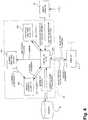
Fig. 3 , a method for hip replacement surgery incorporating surgical parameter measurements in accordance with the present disclosure is generally shown at 100. It is pointed out that themethod 100 is a hip replacement method incorporating additional surgical parameter measurement steps to provide the operator with supplemental information. Accordingly, themethod 100 is associated with existing hip replacement methods, such as the method described in United States Publication No.2004/0230199 by Jansen et al., published November 18, 2004 . Moreover, although themethod 100 is described with a given sequence of steps, some digitizing steps may be suitably switched with surgical steps in accordance with the surgical method chosen by the operator. Although themethod 100 is referred to in the singular, various choices of procedure will be given to the surgeon, as will be set forth in the forthcoming description, according to the preferences of the surgeon. A plurality of methods can be derived from themethod 100 according to the decisions of the surgeon. - It is pointed out that the following definitions will be used in this document: pre-operative refers to the pre-dislocation period, intraoperative refers to the post-reduction period and postoperative refers to the post surgery period.
- In
Step 102, preparative steps for surgery are effected. Namely, general patient information can be entered into the CAS system 50 (Fig. 2 ) for opening a patient file. For instance, a general patient profile can be entered, that can consist of the name, birth date, identification number, sex and the like, as well as more specific data pertaining to the surgery, such as preoperative leg length discrepancy (with the identification of the longer leg), if applicable. For instance, the preoperative leg length discrepancy is measured using X-rays of the hip joint. More precisely, the leg length discrepancy is measured from the vertical comparison between the trochanters. These X-rays are typically taken during the diagnostic stages leading to surgery, so they are usually available for hip joint surgery. The calibration of the various surgical tools to be used is done. For instance, a calibration base and method, as set forth in International Publication No.WO 01/67979 A1 by Jutras et al. tools 56 and the display on theCAS controller 52 can be verified in further calibration steps included inStep 102. - It is pointed out that the general patient information can be entered preoperatively. Moreover, the entering of the general patient information is straightforward such that the surgeon need not be involved. However, in order to minimize the preoperative procedures, all steps of
method 100 can be performed at the beginning of the surgical session, during a short time span preceding the surgery. - Surgery is initiated between
Step 102 andsubsequent Step 104, by the surgeon exposing the hip joint. No computer assistance is required thereat. - In
Step 104, a tracking reference (included in the tools 56) is secured to thepelvis 10. Therefore, thepelvis 10 can be tracked for position and orientation in space as a function of the tracking reference, by theCAS system 50 ofFig. 2 . - In
Step 106, another tracking reference is secured to thefemur 20, for the tracking thereof for position and orientation. In order to reduce the invasiveness of the surgery, the use of a femoral tracking reference is optional, hence Step 106 is optional, as is illustrated inFig. 3 . The tracking references will remain anchored to their respective bones (if applicable) throughout the computer-assisted steps of surgery. TheCAS system 50 must thus be adapted to track at least two tracking references simultaneously, and in real time. An interrelation between the two tracking references is preferably digitized at a given position of the leg. For instance, it is suggested to align the leg along the longitudinal axis of the body, and bend the knee at 90 degrees, to then digitize a relation between the trackable references. - Step 108 consists in the digitization of the acetabular and preoperative femoral coordinate systems, i.e., the acetabular frame of reference and the preoperative femoral frame of reference.
- The acetabular coordinate system is digitized with a registration pointer from the
tools 56. Various methods can be used to define an acetabular coordinate system. In one contemplated embodiment, three points are taken on thepelvis 10 to create the acetabular coordinate system. Referring toFig. 1 , there is one point on theiliac crest 12 of the operated side, one point on the contra lateraliliac crest 13, and one point on one of the twopubic tubercles 14 of thepelvis 10. To be generally aligned, the points digitized on the iliac crests 12 and 13 are taken at the outermost anterior point of the iliac crests 12 and 13. The points digitized on the iliac crests 12 and 13 are preferably taken directly on the soft tissue covering the bone pelvis on the iliac crests, as the soft tissue is relatively thin thereon. The point on thepubic tubercle 14 completes a first plane, the frontal plane (a.k.a. the coronal plane). A second plane, the transverse plane (a.k.a. the horizontal plane), is perpendicular to the frontal plane and includes the points on the iliac crests. A third plane, the sagittal plane, is perpendicular to the frontal and transverse planes. - Supplemental information regarding the frontal plane can be obtained for various postures of a patient, as described in International Publication No.
WO 2004/030559 by Jansen et al., published on April 15, 2004 . For instance, trackable references can be used to gather information about sitting, standing and walking postures. This information can be used to adjust the orientation of the frontal plane, as these postures can provide information not available from the typical lying posture in which a patient is during surgery. This information can influence the anteversion positioning of the implants. - Also in
Step 108, the preoperative femoral coordinate system is digitized. Various methods can be used to define the femoral coordinate system, and this will be dependent on whether a trackable reference is used for the femur (i.e., optional Step 106). - In one contemplated embodiment, the preoperative femoral coordinate system is defined by obtaining an anatomical axis, a mechanical axis and various planes for the
femur 20. It is considered to provide five points of reference on the leg to theCAS controller 52, which is equipped with software that will create the femoral coordinate system. - Referring to
Fig. 1 , a first point is taken on the tip of thegreater trochanter 23 of thefemur 20, and will be defined as a starting point of an anatomical axis of thefemur 20. Thereafter, points are taken on the medial andlateral epicondyles femur 20, respectively. A midpoint between the medial epicondyle and lateral epicondyle points, in alignment therewith, is defined as an endpoint of the anatomical axis of the femur. Alternatively, a point on the patella can be digitized. The fourth and fifth points are taken on themedial malleolus 31 of thetibia 30 and on thelateral malleolus 41 of thefibula 40, with the leg being bent at the knee. - By having the leg bent at the knee, the
tibia 30 stands on theposterior condyles 26 of thefemur 20. Therefore, an assumption is made wherein an aligned midpoint of the medial and lateral malleoli points is said to define a plane (i.e., sagittal plane) with the anatomical axis, with an axis of the knee being normal to the sagittal plane. The frontal plane is perpendicular to the sagittal plane, with the anatomical axis lying therein. The transverse plane is perpendicular to the sagittal and frontal planes, and can be positioned at any height. It is noted that it is not required to measure two points to obtain a midpoint of the malleolus region. As this latter point will be in the sagittal plane, the only requirement is that a point is taken at a midpoint of the malleolus region, and may thus be placed approximately by the operator. - Also in
Step 108, a registration of the mechanical axis of the femur, which will become a femoral reference axis, is performed. The registration of the mechanical axis will be dependent on whether only a tracking reference on the pelvis is used, as inStep 104, or whether the femur also supports a tracking reference, as optionally performed inStep 106. - For the purposes of
method 100, the mechanical axis of thefemur 20 passes through a midpoint of the medial andlateral epicondyles Step 108, and a center of rotation of the hip joint. The digitization of the center of rotation of the hip joint will be dependent on the number of tracking references, as exposed above (either one or two tracking references). - If only one tracking reference is used, namely with the pelvis, a temporary tracking reference is positioned in a stable manner to the
femur 20, and rotational movements of thefemur 20 with respect to thepelvis 10 are performed. Accordingly, these movements will enable theCAS system 50 to calculate a center of rotation of thehip joint 10, and an assumption is then made that the center of rotation of thefemur 20 is coincident with the center of rotation of theacetabulum 11. The calculated center of rotation of the hip joint will then be associated with the tracking reference on the pelvis. This method for obtaining the center of rotation of the hip joint 10 can also be performed if a tracking reference is provided on thefemur 20. It is also contemplated to track a reamer from the tools 56 (Fig. 2 ) so as to obtain, in view of the geometry of the reamer, a position for the center of rotation of theacetabulum 11. - Another method contemplated for obtaining the center of rotation of the
hip joint 10 is to digitize points in the acetabulum 11 with respect to the tracking reference on thepelvis 10. This method also assumes that the centers of rotation of the femur and the pelvis are coincident. Some references, such asU.S. Publication No. 2004/0230199 , have already exposed this method of obtaining the center of rotation of thehip joint 10. - If the femur is also provided with a tracking reference, the center of rotation of the femoral head can be determined by digitizing points on the surface of the femoral head, as exposed in
U.S. Publication No. 2004/0230199 . The mechanical axis passes through the center of rotation and the midpoint of theepicondyles - Thereafter, in
Step 110, this digitized mechanical axis must be registered with respect to the acetabular coordinate system in the femoral reference orientation in view of subsequent surgical parameter measurement. The reference orientation of thefemur 20 may be defined as a plurality of positions. However, it has been identified that a reference orientation in which the mechanical axis is at a 3° orientation with respect to the vertical axis of the body in the pelvic frontal plane is well suited to represent a reference orientation for a standing posture of the patient. This reference orientation is registered virtually by theCAS system 50 with respect to the acetabular coordinate system, once the mechanical axis has been obtained. - Surgical parameter measurements will be based upon the femoral reference orientation. For instance, the point on the greater trochanter, as obtained when defining the anatomical axis of the
femur 20 inStep 108, can be used as a landmark for the calculation of medio-lateral offset and limb length discrepancy from preoperative, intraoperative, as well as postoperative data. - In
Step 112, the implant reduction is initiated. As mentioned previously, theStep 112 of implant reduction is dependent on the method of surgery chosen by the operator. Accordingly, few details are given herein, but reference is made toU.S. Publication No. 2004/0230199 , in which a suitable method for performing the implant reduction is described. - Throughout implant reduction, the operator will need surgical parameter measurements to validate the work being performed. The alterations to the
femur 20 and the acetabulum 11 will result in potential changes to the position of the center of rotation of thehip joint 10. - It is therefore necessary to redigitize the center of rotation to perform the surgical parameter measurements with respect to the landmark points (e.g., the anatomical axis point on the greater trochanter), and the leg must not be moved between the digitization of the landmarks if no trackable reference is provided on the femur.
- Therefore,
Step 114 consists in the digitization of an intraoperative femoral coordinate system. The object is to obtain an intraoperative center of rotation for the hip joint 10 so as to redefine the mechanical axis to refer this measurement to the femoral reference orientation acquired inStep 110. The digitization of intraoperative femoral coordinate system inStep 114 will be dependent on a plurality of factors, such as the presence of one or two tracking references, as well as the types of alterations performed in the implant reduction. - For instance, alterations may be performed to the acetabulum 11 in addition to the insertion of a femoral implant to replace the
femoral head 21. In both these cases, the implants will potentially change the position of the center of rotation of theacetabulum 11 and thefemoral head 21. Therefore, in order to redigitize the center of rotation of the acetabulum 11 if an acetabular implant is used, points may be digitized in the acetabular cup or liner implanted in theacetabulum 11. Alternatively, calibration tools can be inserted into the implanted hip joint so as to obtain the center of rotation of theacetabulum 11. One such calibration tool is described in International Publication No.WO 2005/023110 , by the present assignee. - For the center of rotation of the
femur 20, physical models of femoral implant are often provided to the operator for the modelization of the center of rotation of thefemur 20. More specifically, the physical models represent different sizes of femoral implant, and are used to temporarily estimate the leg length and mediolateral offset. - With such physical models, the
femur 20 is readily digitized, for instance, by digitizing surface points on the physical model inserted into thefemur 20, or by reproducing a motion of thefemur 20 with respect to the pelvis, with a tracking reference secured or positioned on thefemur 20. - It is pointed out that the presence of a tracking reference on the
femur 20 has an effect on the intraoperative step of digitizing a center of rotation for the femoral implant (i.e. ball head) 21. Calibration tools can be placed on the femoral implant (physical model if used) so as to obtain the center of rotation of the femoral implant. Alternatively, surface points may be digitized on the surface of the inserted implant. It is noted that in these cases the implant reduction is not required for subsequent calculation of the limb length discrepancy and medio-lateral offset, as the system simulates implant reduction by superimposing the acetabular implant COR and femoral implant COR. - It is therefore required to have a COR for the acetabulum, assumed to be the hip joint and possibly acquired with the calibration tool while the joint is dislocated, which COR will be used subsequently in the alignment of the femur in a selected orientation.
- If no tracking reference is secured to the
femur 20, the leg is reduced with its implant, and at least two points on thefemur 20, excluding the femoral implant (i.e. ball head) center, must be digitized inStep 114 so as to complete the intraoperative femoral coordinate system. It is contemplated to mark points on the bone during the digitization of the preoperative femoral coordinate system inStep 108, at which points the registration pointer from the tools 56 (Fig. 2 ) will be used to digitize known points. It is pointed out that it is important to have thefemur 20 immobilized when taking these points. Once these points are confirmed, they will be related to the same points as measured inStep 108, whereby the intraoperative femoral coordinate system will be completed. - With the intraoperative center of rotation of the hip joint 10 obtained by digitizing the center of rotation of the altered acetabulum with respect to the pelvic trackable reference, the intraoperative mechanical axis (i.e., from the intraoperative center of rotation to the midpoint of the epicondyles) is realigned digitally in the frontal plane with respect to the femoral reference orientation defined previously. As the alignment of the preoperative mechanical axis was calculated previously, the intraoperative and postoperative greater trochanter points can be aligned in the frontal plane with respect to the pelvic trackable reference.
- Therefore, in order to perform the realignment procedure without any femoral trackable reference, the starting point of the anatomical axis obtained in Step 108 (i.e., on the greater trochanter) is redigitized with the reduced femur, whereby the limb length discrepancy can be calculated on the acetabular frontal plane as the vertical spacing between the preoperative and the intraoperative or postoperative landmark (e.g., greater trochanter). Similarly, the medio-lateral offset can be calculated as the difference between the horizontal position of the landmarks in the frontal plane.
- Accordingly, information will be provided to the operator, so as to guide the operator in the alterations to be performed on the
femur 20 in view of the calculated surgical parameters. - In
Decision 118, the limb length discrepancy and the medio-lateral offset calculated inStep 116 may prompt adjustment in theimplant reduction 112. Ultimately, acceptable limb length discrepancy and medio-lateral offset will lead to Step 120 with the completion of the implant reduction. Steps Steps - Various parameters considered during the
method 100 are described below. The target leg length is a desired position for the femoral center of rotation, and is calculated as follows:
- Another guiding parameter to be provided to the surgeon is the current leg length discrepancy. The current leg length discrepancy,(current ΔLL), is calculated as follows:

CAS system 50 as an overall leg length, or as a relative value between leg lengths, with the value 0 representing legs of equal length. - Another guiding parameter to be provided to the surgeon is the current medio-lateral offset. The current medio-lateral offset,(current ΔMLO), is calculated as follows:

- The anteversion of the femoral implant is represented by the angle between the intersection of the frontal plane and the transverse plane and a projection of the neck axis (anticipated for the femoral implant) onto the transverse plane (Step 108).
- Another guiding parameter to be provided to the surgeon is the varus/valgus angle of the femoral implant, which is equivalent to the varus/valgus angle of the tracked rasp. The angle is measured between the projection of the intramedullary canal axis and the projection of the longitudinal rasp axis onto the femoral frontal plane (Step 108), and is displayed to the surgeon in degrees.
- Another guiding parameter to be provided to the surgeon is the distance between the previous femoral center of rotation (i.e., digitized in Step 112) and the current femoral center of rotation. The current femoral center of rotation is calculated as a function of the femoral implant geometry (e.g., the ball head size) and the tracking of the rasp. The distance can be given in X, Y and Z values (e.g., in mm) according to the femoral coordinate system (Step 108).
- Now that the
method 100 has been described in detail, theCAS system 50 will be described in accordance with the preferred embodiment of the present disclosure. Referring toFig. 2 , an operator (e.g., surgeon) is illustrated at S and is guided in performing surgery by theCAS system 50. More specifically, the operator S interacts with thecontroller 52 of theCAS system 50 using the user interfaces of the controller 52 (e.g., mouse, touch-screen display unit, keyboard, sound emitter). As shown inFig. 2 , thecontroller 52 will provide guiding information on themethod 100 to the operator S throughout CAS. The guiding information is for instance retrieved by thecontroller 52 from thedatabase 58, and will guide the operator S in handling thetools 56. - The
tools 56 are each trackable in space for position and orientation by thesensing apparatus 54, such that a position and/or orientation of given components thereof are calculable. As a general basic requirement, thetools 56 include the reference tools, such as the trackable references securable to the bones (Steps 104 and 106), for the creation of frames of reference of the bones. Another one of the requiredtools 56 is a registration tool that will enable to gather surface information about the bones (e.g., Steps 110, 114, 116, etc.). As mentioned previously, the registration tool can be a registration pointer, a tracked photogrammetric sensor, or the like. Finally, a bone altering tool is included in the requiredtools 56, such as a reamer and a rasp, for which uses are associated withStep 112. Also, thetools 56 include the pelvic (impactor) and the femoral implant, that can be tracked for position and orientation, to guide the operator during the insertion. It is pointed out that information relating to the tools (e.g., geometry, position of tip) is either known by the controller 52 (or retrievable from the database 58) or determinable using various steps of calibration. - The
sensing apparatus 54 is connected to thecontroller 52, and transfers position and orientation tracking to thecontroller 52. The position and orientation trackings are used by thecontroller 52 to calculate parameters pertaining to the CAS. More precisely, the position and orientation trackings of the reference tool and registration tool are used to create frames of reference of the pelvis and the femur, as described inSteps Fig. 2 , the frame of reference information is provided to the operator S, for instance using the display unit of thecontroller 52. - For the pelvic implant, an initial center of rotation is calculated with respect to the frame of reference, as described in
Step 108. The acetabular center of rotation will be used with the pelvic frame of reference as references for the alteration of the acetabulum in view of the insertion of the pelvic implant therein. Thedatabase 58 stores information that is retrieved by thecontroller 52 to make the calculation. - The current pelvic and femoral implant positions and orientations are calculated as a function of the position and orientation tracking of the bone altering tools, and of the geometry of the respective implants. Once more, the
controller 52 uses the output of thesensor apparatus 54 and information stored in thedatabase 58 for the calculations, that will be displayed for guiding the operator S. - The
CAS system 50 can operate with active or passive tracking. In a preferred embodiment of the present disclosure, thesensor apparatus 54 is a NDI Polaris® optical tracking apparatus, with appropriate operating software in thecontroller 52. With the Polaris® optical tracking apparatus, passive detectable devices, such as retro-reflective spheres, are used in patterns to be tracked in space for position and orientation. Each one of thetools 56 that requires to be tracked has an own detectable pattern. - The
CAS system 50 must guide the surgeon throughout themethod 100, and relevant information is displayed to ensure the surgeon follows the proper Steps of operation. For instance, when leg length discrepancy values are given, the cranial-caudal convention can be displayed to explain the reading obtained. Animations can be initiated automatically to guide the surgeon, for example, in taking reference points on the various bones, such that the reference points are taken in a given order, or at the right locations. - Referring to
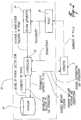
Fig. 4 , theCAS controller 52 is shown in greater detail. TheCAS controller 52 typically is a processing unit having acontroller device 200 which processes the information. Thecontroller device 200 is connected to thesensor apparatus 54 so as to receive position and orientation tracking data of tools, such as the trackable references and the registration tool. - A position and
orientation calculator 202 receives the tracking data, and calculates position and orientation of tools, as well as frames of reference. Therefore, thecontroller device 200 allows the operator S to perform the surgery in real-time CAS navigation. - In order to compare points taken pre-operatively with points taken intra-operatively and post-operatively according to the
method 100, areference orientation adjustor 204 is provided in association with thecontroller device 200. More specifically, updates to data associated with the femoral frame of reference are received by thereference orientation adjustor 204. When the information is complete, thereference orientation adjustor 204 calculates a reference adjustment value that consists in the realignment of the re-digitized frame of reference to the reference orientation. As mentioned previously, this consists in positioning the mechanical axis (with the intraoperative or post-operative center of rotation) at a predetermined angle to the vertical axis in the frontal plane of the pelvic frame of reference, with the centers of rotation of the femur and acetabulum in a known relation. - The reference adjustment value is then provided to a
surgical parameter calculator 206, which will calculate surgical parameters taken into account the reference adjustment value. Therefore, no physical alignment is required considering that theCAS controller 52 performs all alignment virtually.


Claims (9)
- A CAS system (50) for measuring surgical parameters during hip replacement surgery to guide an operator in inserting a hip joint implant in a femur, comprising:at least a first trackable reference (56) in fixed relation with the pelvis, the first trackable reference (56) being trackable to form a pelvic frame of reference;a registration tool (56) being trackable;a sensor apparatus (54) for tracking at least the first trackable reference (56) and the registration tool (56); anda controller unit (52, 200) connected to the sensor apparatus (54) so as to receive tracking data for at least the first trackable reference (56) and the registration tool (56), the controller unit (52, 200) having:a position and orientation calculator (202) to calculate from the tracking data a position and/or orientation of at least the pelvic trackable reference (56) to track the pelvic frame of reference, and of the registration tool (56) to produce a pre-reduction femoral frame of reference at a first operative step and a reduction frame of reference at a sequential second operative step;a reference orientation adjustor (204) connected to the position and orientation calculator (202) so as to receive tracking data for the pelvic frame of reference, the pre-reduction femoral frame of reference and the reduction frame of reference associated with at least the first trackable reference (56), to virtually orient the pre-reduction femoral frame of reference in a reference orientation with respect to the pelvic frame of reference, to virtually realign the reduction frame of reference in the reference orientation, and to produce a reference adjustment value as a function of the realignment of the reduction frame of reference in the reference orientation; anda surgical parameter calculator (206) receiving tracking data from the registration tool (56) to calculate surgical parameters as a function of the reference adjustment value, the surgical parameters at the two sequential operative steps being related by the reference orientation,wherein the reference orientation has a mechanical axis of the pre-reduction femoral frame of reference of the femur at a predetermined angle of a vertical axis of a patient within a frontal plane of the pelvic frame of reference.
- The CAS system (50) according to claim 1, wherein a first of the two sequential operative steps can be performed pre-operatively and a second of the two sequential operative steps can be performed intraoperatively.
- The CAS system (50) according to claim 1, wherein the predetermined angle is 3[deg.].
- The CAS system (50) according to claim 1, wherein the frontal plane of the pelvic frame of reference can be obtained by digitizing two points on the iliac crest and a point on one of the pubic tubercles.
- The CAS system (50) according to claim 1, wherein the mechanical axis of the pre-reduction femoral frame of reference of the femur passes through a center of rotation of the femur, and the reference orientation has the center of rotation of the femur and of the acetabulum coincident.
- The CAS system (50) according to claim 1, wherein the pelvic frame of reference can be updated for the second of the two sequential steps by digitizing a center of rotation of the acetabulum subsequently to an implant reduction.
- The CAS system (50) according to claim 1, wherein the surgical parameters are at least one of the limb length discrepancy and the medio-lateral offset.
- The CAS system (50) according to claim 1, comprising a single one of the trackable references (56) securable to the pelvis.
- The CAS system (50) according to claim 1, comprising two of the trackable references (56), with a second one of the trackable references (56) being connectable to the femur.
Priority Applications (1)
| Application Number | Priority Date | Filing Date | Title |
|---|---|---|---|
| EP18166184.4AEP3372161A1 (en) | 2005-06-02 | 2006-06-01 | Leg alignment for surgical parameter measurement in hip replacement surgery |
Applications Claiming Priority (3)
| Application Number | Priority Date | Filing Date | Title |
|---|---|---|---|
| US68642205P | 2005-06-02 | 2005-06-02 | |
| US69383005P | 2005-06-27 | 2005-06-27 | |
| PCT/CA2006/000905WO2006128301A1 (en) | 2005-06-02 | 2006-06-01 | Leg alignment for surgical parameter measurement in hip replacement surgery |
Related Child Applications (1)
| Application Number | Title | Priority Date | Filing Date |
|---|---|---|---|
| EP18166184.4ADivisionEP3372161A1 (en) | 2005-06-02 | 2006-06-01 | Leg alignment for surgical parameter measurement in hip replacement surgery |
Publications (3)
| Publication Number | Publication Date |
|---|---|
| EP1885274A1 EP1885274A1 (en) | 2008-02-13 |
| EP1885274A4 EP1885274A4 (en) | 2014-01-08 |
| EP1885274B1true EP1885274B1 (en) | 2018-04-25 |
Family
ID=37481191
Family Applications (2)
| Application Number | Title | Priority Date | Filing Date |
|---|---|---|---|
| EP06752743.2AActiveEP1885274B1 (en) | 2005-06-02 | 2006-06-01 | Leg alignment for surgical parameter measurement in hip replacement surgery |
| EP18166184.4AWithdrawnEP3372161A1 (en) | 2005-06-02 | 2006-06-01 | Leg alignment for surgical parameter measurement in hip replacement surgery |
Family Applications After (1)
| Application Number | Title | Priority Date | Filing Date |
|---|---|---|---|
| EP18166184.4AWithdrawnEP3372161A1 (en) | 2005-06-02 | 2006-06-01 | Leg alignment for surgical parameter measurement in hip replacement surgery |
Country Status (7)
| Country | Link |
|---|---|
| US (1) | US7955280B2 (en) |
| EP (2) | EP1885274B1 (en) |
| JP (1) | JP4621774B2 (en) |
| AU (1) | AU2006254688B2 (en) |
| CA (1) | CA2607036C (en) |
| ES (1) | ES2668844T3 (en) |
| WO (1) | WO2006128301A1 (en) |
Families Citing this family (52)
| Publication number | Priority date | Publication date | Assignee | Title |
|---|---|---|---|---|
| US8337508B2 (en)* | 2006-03-20 | 2012-12-25 | Perception Raisonnement Action En Medecine | Distractor system |
| CA2658510C (en) | 2006-07-21 | 2013-01-15 | Orthosoft Inc. | Non-invasive tracking of bones for surgery |
| US20080146969A1 (en)* | 2006-12-15 | 2008-06-19 | Kurtz William B | Total joint replacement component positioning as predetermined distance from center of rotation of the joint using pinless navigation |
| US8784425B2 (en) | 2007-02-28 | 2014-07-22 | Smith & Nephew, Inc. | Systems and methods for identifying landmarks on orthopedic implants |
| US8814868B2 (en) | 2007-02-28 | 2014-08-26 | Smith & Nephew, Inc. | Instrumented orthopaedic implant for identifying a landmark |
| US20090125117A1 (en)* | 2007-11-14 | 2009-05-14 | Francois Paradis | Leg alignment and length measurement in hip replacement surgery |
| US9220514B2 (en) | 2008-02-28 | 2015-12-29 | Smith & Nephew, Inc. | System and method for identifying a landmark |
| GB0803725D0 (en) | 2008-02-29 | 2008-04-09 | Depuy Int Ltd | Surgical apparatus and procedure |
| JP5216949B2 (en)* | 2008-06-04 | 2013-06-19 | 国立大学法人 東京大学 | Surgery support device |
| US8588892B2 (en) | 2008-12-02 | 2013-11-19 | Avenir Medical Inc. | Method and system for aligning a prosthesis during surgery using active sensors |
| EP2216728B1 (en)* | 2009-02-04 | 2012-04-04 | BrainLAB AG | Method and device for determining a characteristic of an anatomical structure |
| US9031637B2 (en) | 2009-04-27 | 2015-05-12 | Smith & Nephew, Inc. | Targeting an orthopaedic implant landmark |
| US8945147B2 (en) | 2009-04-27 | 2015-02-03 | Smith & Nephew, Inc. | System and method for identifying a landmark |
| US9901405B2 (en) | 2010-03-02 | 2018-02-27 | Orthosoft Inc. | MEMS-based method and system for tracking a femoral frame of reference |
| RU2012157125A (en) | 2010-06-03 | 2014-07-20 | Смит Энд Нефью, Инк. | ORTHOPEDIC IMPLANT |
| KR20130129246A (en) | 2010-12-17 | 2013-11-27 | 아브니르 메디컬 아이엔씨. | Method and system for aligning a prosthesis during surgery |
| WO2012103169A2 (en) | 2011-01-25 | 2012-08-02 | Smith & Nephew, Inc. | Targeting operation sites |
| RU2013153116A (en) | 2011-05-06 | 2015-06-20 | Смит Энд Нефью, Инк. | TARGETING FOR SIGNIFICANT POINTS OF ORTHOPEDIC DEVICES |
| WO2012173890A2 (en) | 2011-06-16 | 2012-12-20 | Smith & Nephew, Inc. | Surgical alignment using references |
| US9167989B2 (en) | 2011-09-16 | 2015-10-27 | Mako Surgical Corp. | Systems and methods for measuring parameters in joint replacement surgery |
| US9314188B2 (en) | 2012-04-12 | 2016-04-19 | Intellijoint Surgical Inc. | Computer-assisted joint replacement surgery and navigation systems |
| WO2013186690A2 (en)* | 2012-06-11 | 2013-12-19 | Koninklijke Philips N.V. | Radiolabeled analog(s) of compound 0118 and use thereof in connection with pet and/or spect imaging to determine whether a pharmaceutical containing compound 0118 is a candidate cancer treatment for a patient |
| DE102012108151A1 (en)* | 2012-09-03 | 2014-03-06 | Aesculap Ag | Method for determining craniocaudal length change and mediolateral change femur offset, involves calculating spatial change of location coordinates and projecting spatial change of location coordinates to craniocaudal reference direction |
| US10779751B2 (en)* | 2013-01-25 | 2020-09-22 | Medtronic Navigation, Inc. | System and process of utilizing image data to place a member |
| US9247998B2 (en) | 2013-03-15 | 2016-02-02 | Intellijoint Surgical Inc. | System and method for intra-operative leg position measurement |
| US9408557B2 (en)* | 2013-03-18 | 2016-08-09 | Orthosensor Inc. | System and method to change a contact point of the muscular-skeletal system |
| US11793424B2 (en)* | 2013-03-18 | 2023-10-24 | Orthosensor, Inc. | Kinetic assessment and alignment of the muscular-skeletal system and method therefor |
| US9642560B2 (en) | 2013-04-03 | 2017-05-09 | Brainlab Ag | Method and device for determining the orientation of a co-ordinate system of an anatomical object in a global co-ordinate system |
| WO2014168798A1 (en)* | 2013-04-08 | 2014-10-16 | Elwha Llc | Apparatus, system, and method for controlling movement of an orthopedic joint prosthesis in a mammalian subject |
| US10420666B2 (en) | 2013-04-08 | 2019-09-24 | Elwha Llc | Apparatus, system, and method for controlling movement of an orthopedic joint prosthesis in a mammalian subject |
| US9439797B2 (en) | 2013-04-08 | 2016-09-13 | Elwha Llc | Apparatus, system, and method for controlling movement of an orthopedic joint prosthesis in a mammalian subject |
| JP2017507689A (en)* | 2014-01-10 | 2017-03-23 | アーオー テクノロジー アクチエンゲゼルシャフト | Method for generating a 3D reference computer model of at least one anatomical structure |
| US12295772B2 (en) | 2014-02-25 | 2025-05-13 | DePuy Synthes Products, Inc. | Systems and methods for intra-operative image analysis |
| US10433914B2 (en) | 2014-02-25 | 2019-10-08 | JointPoint, Inc. | Systems and methods for intra-operative image analysis |
| US10758198B2 (en) | 2014-02-25 | 2020-09-01 | DePuy Synthes Products, Inc. | Systems and methods for intra-operative image analysis |
| WO2016007492A1 (en)* | 2014-07-07 | 2016-01-14 | Smith & Nephew, Inc. | Alignment precision |
| US20170333136A1 (en) | 2014-10-29 | 2017-11-23 | Intellijoint Surgical Inc. | Systems and devices including a surgical navigation camera with a kinematic mount and a surgical drape with a kinematic mount adapter |
| US10413428B2 (en) | 2015-02-02 | 2019-09-17 | Orthosoft Inc. | Leg length calculation in computer-assisted surgery |
| WO2017011576A2 (en) | 2015-07-13 | 2017-01-19 | Mako Surgical Corp. | Lower extremities leg length calculation method |
| EP3405926B1 (en)* | 2015-12-18 | 2022-09-28 | DePuy Synthes Products, Inc. | Systems and methods for intra-operative image analysis |
| EP3402409B1 (en)* | 2016-01-13 | 2024-02-28 | DePuy Synthes Products, Inc. | Systems and methods for intra-operative image analysis |
| US10828175B2 (en)* | 2016-03-03 | 2020-11-10 | Orthosensor Inc. | Orthopedic leg alignment system and method |
| WO2017185170A1 (en) | 2016-04-28 | 2017-11-02 | Intellijoint Surgical Inc. | Systems, methods and devices to scan 3d surfaces for intra-operative localization |
| US10182871B2 (en) | 2016-05-22 | 2019-01-22 | JointPoint, Inc. | Systems and methods for intra-operative image acquisition and calibration |
| KR102299132B1 (en)* | 2016-08-30 | 2021-09-08 | 마코 서지컬 코포레이션 | Intraoperative pelvic registration systems and methods |
| US11446090B2 (en) | 2017-04-07 | 2022-09-20 | Orthosoft Ulc | Non-invasive system and method for tracking bones |
| CA3053904A1 (en) | 2018-08-31 | 2020-02-29 | Orthosoft Inc. | System and method for tracking bones |
| WO2020227832A1 (en)* | 2019-05-15 | 2020-11-19 | Intellijoint Surgical Inc. | Systems and methods for computer assisted femoral surgery |
| US11107586B1 (en) | 2020-06-24 | 2021-08-31 | Cuptimize, Inc. | System and method for analyzing acetabular cup position |
| US11887306B2 (en) | 2021-08-11 | 2024-01-30 | DePuy Synthes Products, Inc. | System and method for intraoperatively determining image alignment |
| JP7704965B2 (en)* | 2021-08-30 | 2025-07-08 | アースレックス インコーポレイテッド | Surgical planning system and method for preoperative assessment of center of rotation data - Patents.com |
| KR102477758B1 (en)* | 2021-11-16 | 2022-12-16 | 주식회사 셀루메드 | Patient-specific pin guide design method to prevent hyperextension in the sagittal plane during total knee arthroplasty using a computer-assisted surgical system |
Family Cites Families (10)
| Publication number | Priority date | Publication date | Assignee | Title |
|---|---|---|---|---|
| US5814050A (en)* | 1992-05-14 | 1998-09-29 | Bentwood Place, Inc. | Hip offset-inset apparatus and method |
| US5318571A (en) | 1992-05-14 | 1994-06-07 | Benson Gail M | Method and apparatus for simplifying total hip arthroplasty |
| GB2303942A (en) | 1995-07-28 | 1997-03-05 | Armstrong Projects Ltd | Aligning cannula or guide with line on X-ray images |
| JP2003534035A (en) | 2000-03-15 | 2003-11-18 | オーソソフト インコーポレイテッド | Automatic calibration system for computer assisted surgical instruments |
| NO20011769D0 (en)* | 2001-04-06 | 2001-04-06 | Bjoern Franc Iversen | Device and system for mutual positioning of prosthetic parts |
| US6711431B2 (en)* | 2002-02-13 | 2004-03-23 | Kinamed, Inc. | Non-imaging, computer assisted navigation system for hip replacement surgery |
| US7634306B2 (en)* | 2002-02-13 | 2009-12-15 | Kinamed, Inc. | Non-image, computer assisted navigation system for joint replacement surgery with modular implant system |
| JP2006509609A (en)* | 2002-10-04 | 2006-03-23 | オルトソフト インコーポレイテッド | Computer-aided hip replacement surgery |
| EP1615577A2 (en)* | 2003-02-04 | 2006-01-18 | Orthosoft, Inc. | Cas modular bone reference assembly and limb position measurement system |
| CA2439850A1 (en) | 2003-09-04 | 2005-03-04 | Orthosoft Inc. | Universal method for determining acetabular and femoral implant positions during navigation |
- 2006
- 2006-06-01EPEP06752743.2Apatent/EP1885274B1/enactiveActive
- 2006-06-01AUAU2006254688Apatent/AU2006254688B2/ennot_activeCeased
- 2006-06-01USUS11/421,572patent/US7955280B2/enactiveActive
- 2006-06-01WOPCT/CA2006/000905patent/WO2006128301A1/ennot_activeApplication Discontinuation
- 2006-06-01EPEP18166184.4Apatent/EP3372161A1/ennot_activeWithdrawn
- 2006-06-01JPJP2008513883Apatent/JP4621774B2/ennot_activeExpired - Fee Related
- 2006-06-01ESES06752743.2Tpatent/ES2668844T3/enactiveActive
- 2006-06-01CACA2607036Apatent/CA2607036C/enactiveActive
Non-Patent Citations (1)
| Title |
|---|
| None* |
Also Published As
| Publication number | Publication date |
|---|---|
| US7955280B2 (en) | 2011-06-07 |
| EP1885274A4 (en) | 2014-01-08 |
| EP1885274A1 (en) | 2008-02-13 |
| JP4621774B2 (en) | 2011-01-26 |
| WO2006128301A1 (en) | 2006-12-07 |
| AU2006254688B2 (en) | 2011-09-29 |
| ES2668844T3 (en) | 2018-05-22 |
| CA2607036C (en) | 2013-07-23 |
| CA2607036A1 (en) | 2006-12-07 |
| US20060293614A1 (en) | 2006-12-28 |
| AU2006254688A1 (en) | 2006-12-07 |
| EP3372161A1 (en) | 2018-09-12 |
| JP2008545481A (en) | 2008-12-18 |
Similar Documents
| Publication | Publication Date | Title |
|---|---|---|
| EP1885274B1 (en) | Leg alignment for surgical parameter measurement in hip replacement surgery | |
| US11311339B2 (en) | Computer-assisted hip replacement surgery | |
| AU2008323521B2 (en) | Leg alignment and length measurement in hip replacement surgery | |
| US20200359957A1 (en) | Method and system for tracking tools in computer-assisted surgery | |
| EP1841372B1 (en) | Computer-assisted hip joint resurfacing method and system | |
| AU2008310269B2 (en) | Hip replacement in computer-assisted surgery | |
| US8177850B2 (en) | Joint placement methods and apparatuses |
Legal Events
| Date | Code | Title | Description |
|---|---|---|---|
| PUAI | Public reference made under article 153(3) epc to a published international application that has entered the european phase | Free format text:ORIGINAL CODE: 0009012 | |
| 17P | Request for examination filed | Effective date:20071123 | |
| AK | Designated contracting states | Kind code of ref document:A1 Designated state(s):AT BE BG CH CY CZ DE DK EE ES FI FR GB GR HU IE IS IT LI LT LU LV MC NL PL PT RO SE SI SK TR | |
| RIN1 | Information on inventor provided before grant (corrected) | Inventor name:RADINSKY, ILIYA Inventor name:CHASS , MELANIE Inventor name:ODERMATT, DANIEL Inventor name:AMIOT, LOUIS-PHILIPPE | |
| DAX | Request for extension of the european patent (deleted) | ||
| A4 | Supplementary search report drawn up and despatched | Effective date:20131211 | |
| RIC1 | Information provided on ipc code assigned before grant | Ipc:A61B 17/74 20060101ALI20131205BHEP Ipc:A61B 19/00 20060101AFI20131205BHEP Ipc:A61B 5/00 20060101ALI20131205BHEP Ipc:A61B 5/107 20060101ALI20131205BHEP Ipc:A61F 2/32 20060101ALI20131205BHEP Ipc:A61B 5/103 20060101ALI20131205BHEP Ipc:A61B 17/17 20060101ALN20131205BHEP Ipc:A61F 2/46 20060101ALN20131205BHEP | |
| 17Q | First examination report despatched | Effective date:20151111 | |
| STAA | Information on the status of an ep patent application or granted ep patent | Free format text:STATUS: EXAMINATION IS IN PROGRESS | |
| REG | Reference to a national code | Ref country code:DE Ref legal event code:R079 Ref document number:602006055241 Country of ref document:DE Free format text:PREVIOUS MAIN CLASS: A61B0019000000 Ipc:A61B0005107000 | |
| GRAP | Despatch of communication of intention to grant a patent | Free format text:ORIGINAL CODE: EPIDOSNIGR1 | |
| STAA | Information on the status of an ep patent application or granted ep patent | Free format text:STATUS: GRANT OF PATENT IS INTENDED | |
| RIC1 | Information provided on ipc code assigned before grant | Ipc:A61B 5/107 20060101AFI20171010BHEP Ipc:A61B 5/103 20060101ALI20171010BHEP Ipc:A61B 34/00 20160101ALN20171010BHEP Ipc:A61B 34/20 20160101ALN20171010BHEP Ipc:A61F 2/46 20060101ALN20171010BHEP Ipc:A61B 5/00 20060101ALI20171010BHEP Ipc:A61B 90/00 20160101ALN20171010BHEP Ipc:A61B 34/10 20160101ALN20171010BHEP Ipc:A61F 2/32 20060101ALI20171010BHEP Ipc:A61B 17/74 20060101ALI20171010BHEP Ipc:A61B 17/17 20060101ALN20171010BHEP | |
| INTG | Intention to grant announced | Effective date:20171106 | |
| RIN1 | Information on inventor provided before grant (corrected) | Inventor name:RADINSKY, ILIYA Inventor name:AMIOT, LOUIS-PHILIPPE Inventor name:CHASSE , MELANIE Inventor name:ODERMATT, DANIEL | |
| GRAA | (expected) grant | Free format text:ORIGINAL CODE: 0009210 | |
| GRAS | Grant fee paid | Free format text:ORIGINAL CODE: EPIDOSNIGR3 | |
| STAA | Information on the status of an ep patent application or granted ep patent | Free format text:STATUS: THE PATENT HAS BEEN GRANTED | |
| AK | Designated contracting states | Kind code of ref document:B1 Designated state(s):AT BE BG CH CY CZ DE DK EE ES FI FR GB GR HU IE IS IT LI LT LU LV MC NL PL PT RO SE SI SK TR | |
| REG | Reference to a national code | Ref country code:GB Ref legal event code:FG4D | |
| REG | Reference to a national code | Ref country code:CH Ref legal event code:EP | |
| REG | Reference to a national code | Ref country code:CH Ref legal event code:NV Representative=s name:MICHELI AND CIE SA, CH Ref country code:AT Ref legal event code:REF Ref document number:991982 Country of ref document:AT Kind code of ref document:T Effective date:20180515 | |
| REG | Reference to a national code | Ref country code:IE Ref legal event code:FG4D | |
| REG | Reference to a national code | Ref country code:ES Ref legal event code:FG2A Ref document number:2668844 Country of ref document:ES Kind code of ref document:T3 Effective date:20180522 | |
| REG | Reference to a national code | Ref country code:DE Ref legal event code:R096 Ref document number:602006055241 Country of ref document:DE | |
| REG | Reference to a national code | Ref country code:FR Ref legal event code:PLFP Year of fee payment:13 | |
| REG | Reference to a national code | Ref country code:NL Ref legal event code:MP Effective date:20180425 | |
| REG | Reference to a national code | Ref country code:LT Ref legal event code:MG4D | |
| PG25 | Lapsed in a contracting state [announced via postgrant information from national office to epo] | Ref country code:NL Free format text:LAPSE BECAUSE OF FAILURE TO SUBMIT A TRANSLATION OF THE DESCRIPTION OR TO PAY THE FEE WITHIN THE PRESCRIBED TIME-LIMIT Effective date:20180425 | |
| PG25 | Lapsed in a contracting state [announced via postgrant information from national office to epo] | Ref country code:FI Free format text:LAPSE BECAUSE OF FAILURE TO SUBMIT A TRANSLATION OF THE DESCRIPTION OR TO PAY THE FEE WITHIN THE PRESCRIBED TIME-LIMIT Effective date:20180425 Ref country code:BG Free format text:LAPSE BECAUSE OF FAILURE TO SUBMIT A TRANSLATION OF THE DESCRIPTION OR TO PAY THE FEE WITHIN THE PRESCRIBED TIME-LIMIT Effective date:20180725 Ref country code:PL Free format text:LAPSE BECAUSE OF FAILURE TO SUBMIT A TRANSLATION OF THE DESCRIPTION OR TO PAY THE FEE WITHIN THE PRESCRIBED TIME-LIMIT Effective date:20180425 Ref country code:LT Free format text:LAPSE BECAUSE OF FAILURE TO SUBMIT A TRANSLATION OF THE DESCRIPTION OR TO PAY THE FEE WITHIN THE PRESCRIBED TIME-LIMIT Effective date:20180425 Ref country code:SE Free format text:LAPSE BECAUSE OF FAILURE TO SUBMIT A TRANSLATION OF THE DESCRIPTION OR TO PAY THE FEE WITHIN THE PRESCRIBED TIME-LIMIT Effective date:20180425 | |
| PG25 | Lapsed in a contracting state [announced via postgrant information from national office to epo] | Ref country code:LV Free format text:LAPSE BECAUSE OF FAILURE TO SUBMIT A TRANSLATION OF THE DESCRIPTION OR TO PAY THE FEE WITHIN THE PRESCRIBED TIME-LIMIT Effective date:20180425 Ref country code:GR Free format text:LAPSE BECAUSE OF FAILURE TO SUBMIT A TRANSLATION OF THE DESCRIPTION OR TO PAY THE FEE WITHIN THE PRESCRIBED TIME-LIMIT Effective date:20180726 | |
| REG | Reference to a national code | Ref country code:AT Ref legal event code:MK05 Ref document number:991982 Country of ref document:AT Kind code of ref document:T Effective date:20180425 | |
| PG25 | Lapsed in a contracting state [announced via postgrant information from national office to epo] | Ref country code:PT Free format text:LAPSE BECAUSE OF FAILURE TO SUBMIT A TRANSLATION OF THE DESCRIPTION OR TO PAY THE FEE WITHIN THE PRESCRIBED TIME-LIMIT Effective date:20180827 | |
| REG | Reference to a national code | Ref country code:DE Ref legal event code:R097 Ref document number:602006055241 Country of ref document:DE | |
| PG25 | Lapsed in a contracting state [announced via postgrant information from national office to epo] | Ref country code:DK Free format text:LAPSE BECAUSE OF FAILURE TO SUBMIT A TRANSLATION OF THE DESCRIPTION OR TO PAY THE FEE WITHIN THE PRESCRIBED TIME-LIMIT Effective date:20180425 Ref country code:SK Free format text:LAPSE BECAUSE OF FAILURE TO SUBMIT A TRANSLATION OF THE DESCRIPTION OR TO PAY THE FEE WITHIN THE PRESCRIBED TIME-LIMIT Effective date:20180425 Ref country code:CZ Free format text:LAPSE BECAUSE OF FAILURE TO SUBMIT A TRANSLATION OF THE DESCRIPTION OR TO PAY THE FEE WITHIN THE PRESCRIBED TIME-LIMIT Effective date:20180425 Ref country code:RO Free format text:LAPSE BECAUSE OF FAILURE TO SUBMIT A TRANSLATION OF THE DESCRIPTION OR TO PAY THE FEE WITHIN THE PRESCRIBED TIME-LIMIT Effective date:20180425 Ref country code:EE Free format text:LAPSE BECAUSE OF FAILURE TO SUBMIT A TRANSLATION OF THE DESCRIPTION OR TO PAY THE FEE WITHIN THE PRESCRIBED TIME-LIMIT Effective date:20180425 Ref country code:AT Free format text:LAPSE BECAUSE OF FAILURE TO SUBMIT A TRANSLATION OF THE DESCRIPTION OR TO PAY THE FEE WITHIN THE PRESCRIBED TIME-LIMIT Effective date:20180425 | |
| PLBE | No opposition filed within time limit | Free format text:ORIGINAL CODE: 0009261 | |
| STAA | Information on the status of an ep patent application or granted ep patent | Free format text:STATUS: NO OPPOSITION FILED WITHIN TIME LIMIT | |
| REG | Reference to a national code | Ref country code:BE Ref legal event code:MM Effective date:20180630 | |
| PG25 | Lapsed in a contracting state [announced via postgrant information from national office to epo] | Ref country code:LU Free format text:LAPSE BECAUSE OF NON-PAYMENT OF DUE FEES Effective date:20180601 Ref country code:MC Free format text:LAPSE BECAUSE OF FAILURE TO SUBMIT A TRANSLATION OF THE DESCRIPTION OR TO PAY THE FEE WITHIN THE PRESCRIBED TIME-LIMIT Effective date:20180425 | |
| 26N | No opposition filed | Effective date:20190128 | |
| PG25 | Lapsed in a contracting state [announced via postgrant information from national office to epo] | Ref country code:BE Free format text:LAPSE BECAUSE OF NON-PAYMENT OF DUE FEES Effective date:20180630 Ref country code:SI Free format text:LAPSE BECAUSE OF FAILURE TO SUBMIT A TRANSLATION OF THE DESCRIPTION OR TO PAY THE FEE WITHIN THE PRESCRIBED TIME-LIMIT Effective date:20180425 | |
| REG | Reference to a national code | Ref country code:CH Ref legal event code:PFA Owner name:ORTHOSOFT ULC, CA Free format text:FORMER OWNER: ORTHOSOFT, INC., CA | |
| REG | Reference to a national code | Ref country code:ES Ref legal event code:PC2A Owner name:ORTHOSOFT ULC Effective date:20191108 | |
| REG | Reference to a national code | Ref country code:DE Ref legal event code:R082 Ref document number:602006055241 Country of ref document:DE Representative=s name:VENNER SHIPLEY LLP, CAMBRIDGE, GB Ref country code:DE Ref legal event code:R081 Ref document number:602006055241 Country of ref document:DE Owner name:ORTHOSOFT ULC, CA Free format text:FORMER OWNER: ORTHOSOFT, INC., MONTREAL, QUEBEC, CA Ref country code:DE Ref legal event code:R082 Ref document number:602006055241 Country of ref document:DE Representative=s name:VENNER SHIPLEY LLP, DE | |
| PG25 | Lapsed in a contracting state [announced via postgrant information from national office to epo] | Ref country code:TR Free format text:LAPSE BECAUSE OF FAILURE TO SUBMIT A TRANSLATION OF THE DESCRIPTION OR TO PAY THE FEE WITHIN THE PRESCRIBED TIME-LIMIT Effective date:20180425 | |
| PG25 | Lapsed in a contracting state [announced via postgrant information from national office to epo] | Ref country code:HU Free format text:LAPSE BECAUSE OF FAILURE TO SUBMIT A TRANSLATION OF THE DESCRIPTION OR TO PAY THE FEE WITHIN THE PRESCRIBED TIME-LIMIT; INVALID AB INITIO Effective date:20060601 | |
| PG25 | Lapsed in a contracting state [announced via postgrant information from national office to epo] | Ref country code:CY Free format text:LAPSE BECAUSE OF FAILURE TO SUBMIT A TRANSLATION OF THE DESCRIPTION OR TO PAY THE FEE WITHIN THE PRESCRIBED TIME-LIMIT Effective date:20180425 | |
| PG25 | Lapsed in a contracting state [announced via postgrant information from national office to epo] | Ref country code:IS Free format text:LAPSE BECAUSE OF FAILURE TO SUBMIT A TRANSLATION OF THE DESCRIPTION OR TO PAY THE FEE WITHIN THE PRESCRIBED TIME-LIMIT Effective date:20180825 | |
| PGFP | Annual fee paid to national office [announced via postgrant information from national office to epo] | Ref country code:IT Payment date:20200520 Year of fee payment:15 | |
| REG | Reference to a national code | Ref country code:DE Ref legal event code:R082 Ref document number:602006055241 Country of ref document:DE Representative=s name:VENNER SHIPLEY GERMANY LLP, DE Ref country code:DE Ref legal event code:R082 Ref document number:602006055241 Country of ref document:DE Representative=s name:VENNER SHIPLEY LLP, DE | |
| PGFP | Annual fee paid to national office [announced via postgrant information from national office to epo] | Ref country code:ES Payment date:20200728 Year of fee payment:15 | |
| PGFP | Annual fee paid to national office [announced via postgrant information from national office to epo] | Ref country code:IE Payment date:20210518 Year of fee payment:16 | |
| PG25 | Lapsed in a contracting state [announced via postgrant information from national office to epo] | Ref country code:IT Free format text:LAPSE BECAUSE OF NON-PAYMENT OF DUE FEES Effective date:20210601 | |
| REG | Reference to a national code | Ref country code:ES Ref legal event code:FD2A Effective date:20220805 | |
| PG25 | Lapsed in a contracting state [announced via postgrant information from national office to epo] | Ref country code:ES Free format text:LAPSE BECAUSE OF NON-PAYMENT OF DUE FEES Effective date:20210602 | |
| PGFP | Annual fee paid to national office [announced via postgrant information from national office to epo] | Ref country code:CH Payment date:20220702 Year of fee payment:17 | |
| PG25 | Lapsed in a contracting state [announced via postgrant information from national office to epo] | Ref country code:IE Free format text:LAPSE BECAUSE OF NON-PAYMENT OF DUE FEES Effective date:20220601 | |
| P01 | Opt-out of the competence of the unified patent court (upc) registered | Effective date:20230526 | |
| REG | Reference to a national code | Ref country code:CH Ref legal event code:PL | |
| PG25 | Lapsed in a contracting state [announced via postgrant information from national office to epo] | Ref country code:CH Free format text:LAPSE BECAUSE OF NON-PAYMENT OF DUE FEES Effective date:20230630 | |
| PGFP | Annual fee paid to national office [announced via postgrant information from national office to epo] | Ref country code:GB Payment date:20240507 Year of fee payment:19 | |
| PGFP | Annual fee paid to national office [announced via postgrant information from national office to epo] | Ref country code:DE Payment date:20240506 Year of fee payment:19 | |
| PGFP | Annual fee paid to national office [announced via postgrant information from national office to epo] | Ref country code:FR Payment date:20240507 Year of fee payment:19 |