EP1884206A1 - Surgical cutting and fastening instrument with distally mounted pneumatically powered rotary drive member - Google Patents
Surgical cutting and fastening instrument with distally mounted pneumatically powered rotary drive memberDownload PDFInfo
- Publication number
- EP1884206A1 EP1884206A1EP07253025AEP07253025AEP1884206A1EP 1884206 A1EP1884206 A1EP 1884206A1EP 07253025 AEP07253025 AEP 07253025AEP 07253025 AEP07253025 AEP 07253025AEP 1884206 A1EP1884206 A1EP 1884206A1
- Authority
- EP
- European Patent Office
- Prior art keywords
- assembly
- distal
- proximal
- cylinder
- elongate shaft
- Prior art date
- Legal status (The legal status is an assumption and is not a legal conclusion. Google has not performed a legal analysis and makes no representation as to the accuracy of the status listed.)
- Granted
Links
Images


Classifications
- A—HUMAN NECESSITIES
- A61—MEDICAL OR VETERINARY SCIENCE; HYGIENE
- A61B—DIAGNOSIS; SURGERY; IDENTIFICATION
- A61B17/00—Surgical instruments, devices or methods
- A—HUMAN NECESSITIES
- A61—MEDICAL OR VETERINARY SCIENCE; HYGIENE
- A61B—DIAGNOSIS; SURGERY; IDENTIFICATION
- A61B17/00—Surgical instruments, devices or methods
- A61B17/068—Surgical staplers, e.g. containing multiple staples or clamps
- A—HUMAN NECESSITIES
- A61—MEDICAL OR VETERINARY SCIENCE; HYGIENE
- A61B—DIAGNOSIS; SURGERY; IDENTIFICATION
- A61B17/00—Surgical instruments, devices or methods
- A61B17/068—Surgical staplers, e.g. containing multiple staples or clamps
- A61B17/072—Surgical staplers, e.g. containing multiple staples or clamps for applying a row of staples in a single action, e.g. the staples being applied simultaneously
- A61B17/07207—Surgical staplers, e.g. containing multiple staples or clamps for applying a row of staples in a single action, e.g. the staples being applied simultaneously the staples being applied sequentially
- A—HUMAN NECESSITIES
- A61—MEDICAL OR VETERINARY SCIENCE; HYGIENE
- A61B—DIAGNOSIS; SURGERY; IDENTIFICATION
- A61B17/00—Surgical instruments, devices or methods
- A61B17/10—Surgical instruments, devices or methods for applying or removing wound clamps, e.g. containing only one clamp or staple; Wound clamp magazines
- A—HUMAN NECESSITIES
- A61—MEDICAL OR VETERINARY SCIENCE; HYGIENE
- A61B—DIAGNOSIS; SURGERY; IDENTIFICATION
- A61B17/00—Surgical instruments, devices or methods
- A61B17/12—Surgical instruments, devices or methods for ligaturing or otherwise compressing tubular parts of the body, e.g. blood vessels or umbilical cord
- A61B17/122—Clamps or clips, e.g. for the umbilical cord
- A—HUMAN NECESSITIES
- A61—MEDICAL OR VETERINARY SCIENCE; HYGIENE
- A61B—DIAGNOSIS; SURGERY; IDENTIFICATION
- A61B17/00—Surgical instruments, devices or methods
- A61B17/00234—Surgical instruments, devices or methods for minimally invasive surgery
- A61B2017/00292—Surgical instruments, devices or methods for minimally invasive surgery mounted on or guided by flexible, e.g. catheter-like, means
- A61B2017/003—Steerable
- A—HUMAN NECESSITIES
- A61—MEDICAL OR VETERINARY SCIENCE; HYGIENE
- A61B—DIAGNOSIS; SURGERY; IDENTIFICATION
- A61B17/00—Surgical instruments, devices or methods
- A61B2017/00367—Details of actuation of instruments, e.g. relations between pushing buttons, or the like, and activation of the tool, working tip, or the like
- A61B2017/00398—Details of actuation of instruments, e.g. relations between pushing buttons, or the like, and activation of the tool, working tip, or the like using powered actuators, e.g. stepper motors, solenoids
- A—HUMAN NECESSITIES
- A61—MEDICAL OR VETERINARY SCIENCE; HYGIENE
- A61B—DIAGNOSIS; SURGERY; IDENTIFICATION
- A61B17/00—Surgical instruments, devices or methods
- A61B2017/00535—Surgical instruments, devices or methods pneumatically or hydraulically operated
- A61B2017/00544—Surgical instruments, devices or methods pneumatically or hydraulically operated pneumatically
- A61B2017/00548—Gas cartridges therefor
- A—HUMAN NECESSITIES
- A61—MEDICAL OR VETERINARY SCIENCE; HYGIENE
- A61B—DIAGNOSIS; SURGERY; IDENTIFICATION
- A61B17/00—Surgical instruments, devices or methods
- A61B17/28—Surgical forceps
- A61B17/29—Forceps for use in minimally invasive surgery
- A61B2017/2901—Details of shaft
- A61B2017/2902—Details of shaft characterized by features of the actuating rod
- A—HUMAN NECESSITIES
- A61—MEDICAL OR VETERINARY SCIENCE; HYGIENE
- A61B—DIAGNOSIS; SURGERY; IDENTIFICATION
- A61B17/00—Surgical instruments, devices or methods
- A61B17/28—Surgical forceps
- A61B17/29—Forceps for use in minimally invasive surgery
- A61B17/2909—Handles
- A61B2017/2925—Pistol grips
- A—HUMAN NECESSITIES
- A61—MEDICAL OR VETERINARY SCIENCE; HYGIENE
- A61B—DIAGNOSIS; SURGERY; IDENTIFICATION
- A61B17/00—Surgical instruments, devices or methods
- A61B17/28—Surgical forceps
- A61B17/29—Forceps for use in minimally invasive surgery
- A61B2017/2926—Details of heads or jaws
- A61B2017/2927—Details of heads or jaws the angular position of the head being adjustable with respect to the shaft
- A61B2017/2929—Details of heads or jaws the angular position of the head being adjustable with respect to the shaft with a head rotatable about the longitudinal axis of the shaft
- A—HUMAN NECESSITIES
- A61—MEDICAL OR VETERINARY SCIENCE; HYGIENE
- A61B—DIAGNOSIS; SURGERY; IDENTIFICATION
- A61B17/00—Surgical instruments, devices or methods
- A61B17/28—Surgical forceps
- A61B17/29—Forceps for use in minimally invasive surgery
- A61B2017/2946—Locking means
- A—HUMAN NECESSITIES
- A61—MEDICAL OR VETERINARY SCIENCE; HYGIENE
- A61B—DIAGNOSIS; SURGERY; IDENTIFICATION
- A61B90/00—Instruments, implements or accessories specially adapted for surgery or diagnosis and not covered by any of the groups A61B1/00 - A61B50/00, e.g. for luxation treatment or for protecting wound edges
- A61B90/03—Automatic limiting or abutting means, e.g. for safety
- A61B2090/037—Automatic limiting or abutting means, e.g. for safety with a frangible part, e.g. by reduced diameter
- A—HUMAN NECESSITIES
- A61—MEDICAL OR VETERINARY SCIENCE; HYGIENE
- A61B—DIAGNOSIS; SURGERY; IDENTIFICATION
- A61B90/00—Instruments, implements or accessories specially adapted for surgery or diagnosis and not covered by any of the groups A61B1/00 - A61B50/00, e.g. for luxation treatment or for protecting wound edges
- A61B90/06—Measuring instruments not otherwise provided for
- A61B2090/064—Measuring instruments not otherwise provided for for measuring force, pressure or mechanical tension
- A—HUMAN NECESSITIES
- A61—MEDICAL OR VETERINARY SCIENCE; HYGIENE
- A61B—DIAGNOSIS; SURGERY; IDENTIFICATION
- A61B90/00—Instruments, implements or accessories specially adapted for surgery or diagnosis and not covered by any of the groups A61B1/00 - A61B50/00, e.g. for luxation treatment or for protecting wound edges
- A61B90/08—Accessories or related features not otherwise provided for
- A61B2090/0803—Counting the number of times an instrument is used
- A—HUMAN NECESSITIES
- A61—MEDICAL OR VETERINARY SCIENCE; HYGIENE
- A61B—DIAGNOSIS; SURGERY; IDENTIFICATION
- A61B90/00—Instruments, implements or accessories specially adapted for surgery or diagnosis and not covered by any of the groups A61B1/00 - A61B50/00, e.g. for luxation treatment or for protecting wound edges
- A61B90/08—Accessories or related features not otherwise provided for
- A61B2090/0807—Indication means
- A61B2090/0811—Indication means for the position of a particular part of an instrument with respect to the rest of the instrument, e.g. position of the anvil of a stapling instrument
- A—HUMAN NECESSITIES
- A61—MEDICAL OR VETERINARY SCIENCE; HYGIENE
- A61B—DIAGNOSIS; SURGERY; IDENTIFICATION
- A61B90/00—Instruments, implements or accessories specially adapted for surgery or diagnosis and not covered by any of the groups A61B1/00 - A61B50/00, e.g. for luxation treatment or for protecting wound edges
- A61B90/08—Accessories or related features not otherwise provided for
- A61B2090/0814—Preventing re-use
- F—MECHANICAL ENGINEERING; LIGHTING; HEATING; WEAPONS; BLASTING
- F17—STORING OR DISTRIBUTING GASES OR LIQUIDS
- F17C—VESSELS FOR CONTAINING OR STORING COMPRESSED, LIQUEFIED OR SOLIDIFIED GASES; FIXED-CAPACITY GAS-HOLDERS; FILLING VESSELS WITH, OR DISCHARGING FROM VESSELS, COMPRESSED, LIQUEFIED, OR SOLIDIFIED GASES
- F17C2270/00—Applications
- F17C2270/05—Applications for industrial use
- F17C2270/0545—Tools
Definitions
- the present inventiongenerally concerns surgical instruments and, more particularly, pneumatically powered surgical cutting and fastening instruments.
- the present inventionmay have application in conventional endoscopic and open surgical instrumentation as well as application in robotic-assisted surgery.
- Surgical cutting and fastening instrumentshave been used in the prior art to simultaneously make a longitudinal incision in tissue and apply lines of staples on opposing sides of the incision.
- Such instrumentscommonly include a pair of cooperating jaw members that, if the instrument is intended for endoscopic or laparoscopic applications, are capable of passing through a cannula passageway.
- One of the jaw membersreceives a staple cartridge having at least two laterally spaced rows of staples.
- the other jaw memberdefines an anvil having staple-forming pockets aligned with the rows of staples in the cartridge.
- the instrumentincludes a plurality of reciprocating wedges which, when driven distally, pass through openings in the staple cartridge and engage drivers supporting the staples to effect the firing of the staples toward the anvil.
- U.S. Patent No. 6,978,921 to Shelton, IV et al.discloses a surgical stapling instrument that employs tissue severing and staple deployment components that are driven through manual actuation of various trigger mechanisms on the handle.
- Other surgical stapling apparatuseshave been developed that employ battery powered motors. Such a device is disclosed in U.S. Patent No. 5,954,259 to Viola et al.
- Still other surgical staplersare actuated by a source of pressurized gas.
- U.S. Patent No. 6,619,529 to Green et al.discloses a surgical stapler that employs a source of pressurized gas in the handle that is used to power a cylinder that is also located within the handle.
- the cylinderhouses a piston assembly that is actuated by admission of the pressurized gas into the cylinder.
- the pistonis configured to coact with components located in the elongated tube portion and handle member to cause the deployment of the staples and the surgical knife in the distally mounted end effector.
- Such designemploys a complex collection of components for transmitting the motion of the handle-mounted piston to the components located in the end effector portion of the device.
- FIG. 1Another pneumatically powered surgical stapling device is disclosed in US Patent Publication No. US 2006/0151567 to Roy .
- This deviceemploys a pneumatically powered motor or piston system supported in the handle of the device for creating a motion that is employed to actuate the end effector.
- This devicemay be powered by removable cartridges or from an external power source, such as the hospital's existing pneumatic air or gas supply.
- Such pneumatically powered devicesthat employ cartridges or containers in the handle portion of the device are also hampered by the size of the gas cylinder required to store the pressurized gas at sufficient volumes to facilitate actuation of the device a desired number of times at a minimum usable pressure.
- devices designed for large numbers of applications/procedureswould either require a large cylinder to be used or, if smaller cylinders were used, such cylinders would have undesirably high pressures.
- devices that employ removable cartridgesthat can be used an unlimited number of times must be reprocessed and resterilized. Such arrangements can dramatically change performance capabilities and may therefore be less desirable.
- the present inventionis directed to a surgical instrument comprising a distal member that is configured to receive a pneumatically operated tool assembly.
- the instrumentmay include an elongate shaft assembly that has a proximal end portion and a distal end portion. The distal end portion may be coupled to the distal member.
- the instrumentmay further comprise a pneumatically powered drive member that is supported by the distal end portion of the elongate shaft assembly.
- the drive membermay be configured to apply at least two rotary actuation motions to the pneumatically operated tool assembly that is supported in the distal member upon receipt of at least one pneumatic drive signal from the source of pneumatic power.
- the present inventionis directed to a surgical instrument that may include a handle assembly and a closure drive that is operably supported by the handle assembly and is configured to generate a closing motion and an opening motion.
- An actuator mechanismmay also be supported by the handle assembly such that it communicates with a source of pneumatic power to selectively produce at least one pneumatic actuation signal.
- An elongate shaft assemblymay be operably coupled to the handle assembly and communicates with the closure drive to transfer the opening and closing motions as well as the pneumatic actuation signals.
- a pneumatically powered drive membermay be operably supported by a distal end of the elongate shaft assembly and may be configured to generate a rotary firing motion and a rotary retraction motion in response to the pneumatic actuation signals.
- the instrumentmay further comprise an end effector that is coupled to the elongate shaft assembly.
- the end effectorin various non-limiting embodiments may comprise an elongate channel that is sized to receive a staple cartridge therein.
- An anvilis pivotally coupled to the elongate channel and is pivotally responsive to the open and closing motions from the elongate shaft assembly.
- a cutting and severing memberis operably supported within the elongate channel and is responsive to the rotary firing and retraction motions from the pneumatically powered drive member.
- a surgical instrumentcomprising:
- a method for processing the instrument of embodiment 1 for surgerycomprising:
- a surgical instrumentcomprising:
- a surgical instrumentcomprising:
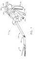
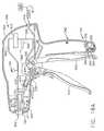
- FIG. 1is a perspective view of an embodiment of a surgical cutting and fastening instrument of the present invention
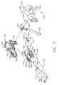
- FIG. 2is an exploded assembly view of an end effector arrangement that may be employed in connection with various embodiments of the present invention
- FIG. 3is a top view of the end effector of FIGS. 1 and 2 with the anvil portion removed therefrom and the closure tube assembly illustrated in phantom lines;
- FIG. 4is a cross-sectional side elevational view of the end effector arrangement of FIG. 3 with the anvil portion attached thereto and shown in an open position;
- FIG. 5is a cross-sectional top view of a portion of an articulation control that may be employed with various embodiments of the present invention
- FIG. 6is a top cross-sectional view illustrating the articulation of the end effector depicted in FIG. 1;
- FIG. 7is an exploded assembly view illustrating an embodiment of a closure tube assembly and shuttle arrangement supported within the handle assembly with other components housed within the housing assembly being omitted for clarity;
- FIG. 8is a cross-sectional view of a housing assembly arrangement of various embodiments of the present invention.
- FIG. 8Ais a partial cross-sectional view of a portion of a closure trigger locking system that may be employed in connection with various embodiments of the present invention.
- FIG. 8Bis a cross-sectional view of another handle assembly embodiment of the present invention wherein the source of pressurized gas is external to the handle assembly;
- FIG. 8Cis a cross-sectional view of another handle assembly embodiment of the present invention.
- FIG. 9is another cross-sectional view of the handle assembly of FIG. 8;
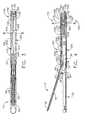
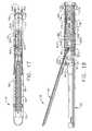
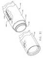
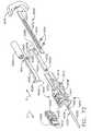
- FIG. 10is a side view of a knife bar arrangement and a firing drive member that comprises a two stage cylinder assembly of various embodiments of the present invention with the cylinder assembly shown in cross-section;
- FIG. 11is another side view of the knife bar and two stage cylinder arrangements depicted in FIG. 10 with the knife bar in the extended position;
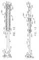
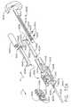
- FIG. 12is a side view of another knife bar and firing drive member arrangement of the present invention with the knife bar being retracted into a cylinder assembly shown in cross-section;
- FIG. 13is another side view of the knife bar and cylinder arrangements depicted in FIG. 12 with the knife bar in the extended position;
- FIG. 14is a top view of an end effector and spine assembly arrangement housing the cylinder and knife bar arrangements depicted in FIGS. 12 and 13;
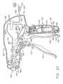
- FIG. 15is a cross-sectional side elevational view of the end effector and spine assembly arrangement depicted in FIG. 14 with the anvil portion attached thereto and in the open position;
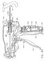
- FIG. 16is a cross-sectional view of a handle assembly that may be used in connection with the embodiment depicted in FIGS. 12-15;
- FIG. 16Ais a cross-sectional view of another handle assembly that may be used in connection with the embodiment depicted in FIGS. 12-1 wherein the source of pressurized gas is external to the handle assembly;
- FIG. 16Bis a cross-sectional view of another handle assembly embodiment of the present invention.
- FIG. 17is a top view of another knife bar and spine assembly arrangement that supports another firing drive member in the form of a bellows assembly of another embodiment of the present invention.
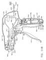
- FIG. 18is a cross-sectional side elevational view of the end effector and spine assembly arrangements of the embodiment depicted in FIG. 17;
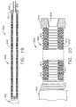
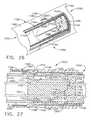
- FIG. 19is a partial cross-sectional assembly view of a bellows assembly of the embodiments depicted in FIGS. 17 and 18;
- FIG. 20is an enlarged view of a portion of the bellows assembly of FIG. 19;
- FIG. 21is a cross-sectional view of a handle assembly embodiment that may be used in connection with the embodiments depicted in FIGS. 17-20;
- FIG. 21Ais a cross-sectional view of another handle assembly embodiment that may be used in connection with the embodiments of FIGS. 17-20 wherein the source of pressurized gas is external to the handle assembly;
- FIG. 21 Bis a cross-sectional view of another handle assembly embodiment of the present invention.
- FIG. 22is a perspective view of another surgical cutting and fastening instrument according to other embodiments of the present invention.
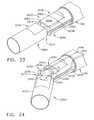
- FIG. 23is a cross-sectional side elevational view of the end effector and spine assembly of the embodiment depicted in FIG. 22;
- FIG. 24is a cross-sectional view of the quick disconnect joint arrangement of the embodiment of FIGS. 22 and 23 prior to coupling the distal shaft assembly to the proximal shaft assembly;
- FIG. 25is a cross-sectional view of the proximal shaft assembly taken along line 25-25 in FIG. 24;
- FIG. 26is a partial perspective view of the distal shaft assembly attached to the proximal shaft assembly with a portion of the distal shaft assembly omitted for clarity;
- FIG. 27is a cross-sectional side elevational view of the joint assembly of the embodiments of FIGS. 24-26 with the distal shaft assembly coupled to the proximal shaft assembly;
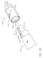
- FIG. 28is a perspective view of a portion of the distal shaft assembly prior to attachment to a portion of the proximal shaft assembly
- FIG. 29is a partial cross-sectional view of another quick disconnect joint arrangement that may be employed with the embodiment depicted in FIGS. 12-16A;
- Fig. 30is a cross-sectional view of the proximal shaft assembly taken along line 30-30 in FIG. 29;
- FIG. 31is a perspective view of a portion of a proximal shaft assembly that may be used in connection with the embodiments depicted in FIGS. 22-30;
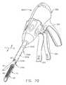
- FIG. 32is a perspective view of another surgical cutting and fastening instrument of the present invention that employs a pneumatically actuated articulation joint of various embodiments of the present invention
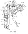
- FIG. 33is a partial perspective view of a portion of the articulation joint attaching a distal spine segment to a proximal spine segment of the embodiment depicted in FIG. 32;
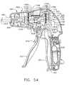
- FIG. 34is another perspective view of the articulation joint arrangement of FIG. 33 with the cover removed therefrom and illustrating the distal spine segment articulated relative to the proximal spine segment;
- FIG. 35is an exploded assembly view of the articulation joint arrangement of FIGS. 33 and 34;
- FIG. 36is a cross-sectional side view of the joint assembly of FIGS. 33-35;
- FIG. 37is a perspective view of a switch assembly embodiment of the present invention.
- FIG. 38is a side elevational view of the switch assembly of FIG. 37;
- FIG. 39is a cross-sectional view of the switch assembly of FIGS. 37 and 38 taken along line 39-39 in FIG. 37;
- FIG. 40is a cross-sectional view of the switch assembly in the off position taken along line 40-40 in FIG. 3 8;
- FIG. 41is another cross-sectional view of the switch assembly of FIGS. 37-40 in an actuated position
- FIG. 42is a cross-sectional view of the switch assembly of FIG. 41 taken along line 42-42 in FIG. 41;
- FIG. 43is a bottom view of the switch assembly of FIGS. 37-42;
- FIG. 44is a cross-sectional view of a handle assembly that has the switch assembly of FIGS. 37-43 therein and houses a source of pressurized gas;
- FIG. 45is a cross-sectional view of a handle assembly that has the switch assembly of FIGS. 37-43 therein and wherein the source of pressurized gas is external to the handle assembly;
- FIG. 46is a perspective view of another surgical stapling and cutting instrument of the present invention that employs the articulation joint embodiments depicted in FIGS. 33-36 and the quick disconnect joint embodiments depicted in FIGS. 23-31;
- FIG. 47is a cross-sectional view of the quick disconnect joint arrangement of the embodiment of FIG. 46 prior to coupling the distal shaft assembly to the proximal shaft assembly;
- FIG. 48is a cross-sectional view of the joint assembly of the embodiments of FIG. 47 taken along line 48-48 in FIG. 47;
- FIG. 49is a perspective view of another surgical cutting and fastening instrument embodiment of the present invention.
- FIG. 50is an exploded assembly view of an end effector arrangement that may be employed in connection with the embodiment depicted in FIG. 49;
- FIG. 51is an exploded assembly view of an end effector arrangement, spine assembly and closure tube assembly that may be employed in connection with the embodiment depicted in FIG. 49;
- FIG. 52is a cross-sectional side elevational view of the end effector, spine assembly and closure tube assembly of FIG. 51 with the anvil portion omitted for clarity;
- FIG. 52Ais a cross-sectional side elevational view of an end effector, spine assembly and closure tube assembly of another non-limiting embodiment of the present invention wherein the pneumatically powered motor is supported distally from the handle assembly;
- FIG. 52Bis a cross-sectional side elevational view of an end effector, spine assembly and closure tube assembly of another non-limiting embodiment of the present invention wherein the pneumatically powered motor is supported distally from the handle assembly;
- FIG. 53is a cross-sectional view of a handle assembly that may be employed in connection with the embodiment of FIG. 49;
- FIG. 53Ais a cross-sectional view of another handle assembly that may be employed with the embodiment of FIG. 49 wherein the source of pressurized gas is external to the handle assembly;
- FIG. 54is another cross-sectional view of the handle assembly of FIG. 53;
- FIG. 55is a side view of a relative position firing trigger arrangement of various embodiments of the present invention.
- FIG. 56is a schematic of a control system embodiment of the present invention that may be employed in connection with various embodiments of the present invention.
- FIG. 57is a cross-sectional view of a detachable grip portion detached from a primary attachment portion of various handle assembly embodiments of the present invention.
- FIG. 58is a partial cross-sectional view showing the detachable grip portion coupled to the primary attachment portion of a handle assembly of various embodiments of the present invention.
- FIG. 59is a partial cross-sectional view of the detachable grip portion and primary attachment portion of FIG. 58 with the headers and cylinder-related components omitted for clarity;
- FIG. 60is a cross-sectional view of the detachable grip portion and primary attachment portion of FIGS. 58 and 59 taken along line 60-60 in FIG. 59;
- FIG. 61is a cross-sectional view of the detachable grip portion and primary attachment portion of FIGS. 58, 59, and 60 taken along line 61-61 in FIG. 59;
- FIG. 62is a cross-sectional view of the detachable grip portion and primary attachment portion of FIGS. 58-61 taken along line 62-62 in FIG. 59;
- FIG. 63is another partial cross-sectional view of the detachable grip portion and primary attachment portion of FIGS. 58-62 taken along line 63-63 in FIG. 59;
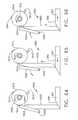
- FIG. 64is a diagrammatic view of a lockout system embodiment of the present invention in an initial position
- FIG. 65is another diagrammatic view of the lockout system of FIG. 64 illustrating the action thereof when the grip portion is initially attached to the primary attachment portion of the handle assembly;
- FIG. 66is another diagrammatic view of the lock out system of FIGS. 64 and 65 prior to the second detachment of the grip portion from the primary attachment portion of the handle assembly;
- FIG. 67is another diagrammatic view of the lock out system of FIGS. 64-66 that illustrates the positions of the system components when the grip portion has been attached to the primary attachment portion;
- FIG. 68is another diagrammatic view of the lock out system of FIGS. 64-67 that illustrates the position of the system components during the second attachment of the grip portion to the primary attachment portion;
- FIG. 69is another diagrammatic view illustrating the lock out system after the grip portion has been attached to the primary attachment portion for the second and final time;
- FIG. 70is a perspective view of another surgical cutting and fastening instrument embodiment of the present invention.
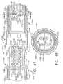
- FIG. 71is a cross-sectional view of a handle assembly embodiment that may be employed in connection with the instrument depicted in FIG. 70;
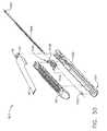
- FIG. 72is an exploded assembly view of a shuttle and retraction rod assembly of various embodiments of the present invention.
- FIG. 72Ais an exploded assembly view of a shuttle and retraction rod assembly of other embodiments of the present invention.
- FIG. 73is an assembled view of the components depicted in FIG. 72 with the cylinder assembly thereof in a fully extended position;
- FIG. 74is a rear elevational view of a shuttle assembly embodiment of the present invention.
- FIG. 75is another rear elevational view of the shuttle assembly of FIG. 74 with the retraction rod and push bar extending into the push bar opening and with the push bar attached to the connector member;
- FIG. 76is a rear elevational perspective view of the left side portion of the shuttle assembly
- FIG. 77is another rear elevational perspective view of the left side portion of the shuttle assembly.
- FIG. 78is a schematic depiction of a control system arrangement that may be used with the embodiments depicted in FIGS. 70-77;
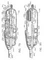
- FIG. 79is a top cross-sectional view of a handle assembly arrangement of the embodiments depicted in FIGS. 70-78 with the cylinder assembly in an extended position;
- FIG. 80is another top cross-sectional view of a handle assembly arrangement of the embodiments depicted in FIGS. 70-79 with the cylinder assembly in a retracted position;
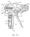
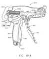
- FIG. 81is a cross-sectional view of a handle assembly of the embodiments depicted in FIGS. 70-80;
- FIG. 81Ais a cross-sectional view of a handle assembly embodiment that may be employed with the embodiment depicted in FIGS 70-80 wherein the source of pressurized gas is external to the handle assembly;
- FIG. 82is another cross-sectional view of the handle assembly of FIG. 81 wherein cylinder assembly is extended;
- FIG. 83is another cross-sectional view of the handle assembly of FIG. 81 wherein cylinder assembly is retracted.
- FIG. 83Ais a cross-sectional view of a handle assembly of the embodiment depicted in FIG. 72B wherein the cylinder assembly is retracted and the firing rod is in its proximal most position.
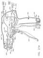
- FIG. 1depicts a surgical stapling and severing instrument 10 that is capable of practicing several unique benefits of the present invention.
- the embodiment illustrated in FIG. 1includes a handle assembly 300, an elongate shaft assembly 100, and an end effector 12 that is connected to the elongate shaft assembly 100.
- Various embodiments of the present inventionmay include an end effector that is pivotally attached to the elongate shaft assembly 100 and pivotally driven by bending cables or bands such as those disclosed in U.S. Patent Application Serial No.
- the handle assembly 300 of the instrument 10may include a closure trigger 302 and a firing trigger 310. It will be appreciated that instruments having end effectors directed to different surgical tasks may have different numbers or types of triggers or other suitable controls for operating an end effector.
- the end effector 12is shown separated from the handle assembly 300 by the preferably elongate shaft assembly 100. A clinician may articulate the end effector 12 relative to the shaft assembly 100 by utilizing an articulation control 200.
- proximalis used to denote a perspective of a clinician who is behind the handle assembly 300 who places the end effector 12 distal, or away from him or herself.
- pressurized gasrefers to any gas suitable for use in pneumatically powered systems employed in a sterile environment.
- mediumsinclude compressed air, carbon dioxide (CO2), Nitrogen, Oxygen, Argon, Helium, Sodium Hydride, Propane, Isobutane, Butane Chlorofluorocarbons, Dimethyl ether.
- HFAHyrdofluoroalkanes
- the term "fluidically coupled”means that the elements are coupled together with an appropriate line or other means to permit the passage of pressurized gas therebetween.
- lineas used herein, the term "line” as used in “supply line” or “return line” refers to an appropriate passage formed from rigid or flexible conduit, pipe, tubing, etc. for transporting pressurized gas from one component to another.
- pneumatic signalor “pneumatic drive signal” refer to the flow of gas from a source of pressurized gas to one or more components that are fluidically coupled to the source of pressurized gas or the flow of gas between components that are fluidically coupled together.
- FIG. 2illustrates an exploded assembly view of one type of pneumatically operated tool assembly or end effector that may be employed in various embodiments of the present invention.
- the pneumatically operated tool assembly 12 shown in FIGS. 1-4is configured to act as an endocutter.
- various unique and novel drive arrangements of embodiments of the present inventioncould also be conceivably employed to drive other end effectors configured to perform other surgical tasks and thus requiring the removal, modification, or addition of components from what is shown in the Figures.
- the end effectors 12 shown in FIGS. 1-4may be customized for specific surgical applications.
- FIG. 2One type of end effector that may be employed with various embodiments of the present invention is depicted in FIG. 2.
- the end effector 12employs an E-beam firing mechanism ("knife assembly") 30 that, in addition to cutting tissue and firing staples located in a staple cylinder seated therein, advantageously controls the spacing of an anvil portion of the end effector 12 relative to the staple cylinder.
- E-beam firing mechanismsare described in U.S. Patent No. 6,978,921 , entitled Surgical Stapling Instrument Incorporating An E-Beam Firing Mechanism to Shelton, IV. et al., the relevant portions of which are herein incorporated by reference.
- knife and firing mechanism configurationsmay be advantageously employed without departing from the spirit and scope of the present invention.
- firing mechanismrefers to the portion or portions of the pneumatically powered tool and/or end effector that move from an unactuated position wherein the firing mechanism may be essentially at rest to an actuated or end position wherein that portion or portions have been moved or repositioned to a final position wherein such movement thereof resulted in the tool completing one or more actions in response to the application of at least one firing motion thereto.
- the firing mechanismmay comprise, for example: (i) components that are completely supported by the pneumatically powered tool and interface with components in the surgical device; (ii) a combination of components that are located in the pneumatically powered tool and in the surgical device; or (ii) components that are supported by the surgical device and are movable into and out of the pneumatically powered tool.
- firing strokerefers to the actual movement of the firing mechanism from the unactuated position to the actuated position.
- retract strokerefers to the return movement of the firing mechanism from the actuated position to the unactuated position.
- the end effector 12includes a distal member that, in various non-limiting embodiments, comprise an elongate channel 20 that has a pivotally translatable anvil 40 attached thereto.
- the elongate channel 20is configured to receive and support a staple cartridge 50 that is responsive to the knife assembly 30 to drive staples 70 into forming contact with the anvil 40.
- a staple cartridge consistent with aspects of the present inventionmay be permanently affixed or integral to the elongate channel 20.
- the firing mechanism or knife assembly 30includes vertically spaced pins that control the spacing of the end effector 12 during firing.
- upper pins 32are staged to enter an anvil pocket 42 near the pivot between the anvil 40 and elongate channel 20. See FIG. 4.
- the upper pins 32advance distally within a longitudinal anvil slot 44 extending distally through anvil 40. Any minor upward deflection in the anvil 40 is overcome by a downward force imparted by the upper pins 32.
- Knife assembly 30also includes a knife bar cap 34 that upwardly engages a channel slot 23 (FIG. 2) formed in the elongate channel 20, thereby cooperating with the upper pins 32 to draw the anvil 40 and the elongate channel 20 slightly closer together in the event of excess tissue clamped therebetween.
- the knife assembly 30may advantageously include middle pins 36 that pass through a firing drive slot (not shown) formed in a lower surface of the cartridge 50 and an upward surface of the elongate channel 20, thereby driving the staples 70 therein as described below.
- the middle pins 36by sliding against the elongate channel 20, advantageously resist any tendency for the end effector 12 to be pinched shut at its distal end.
- the unique and novel aspects of various embodiments of the present inventionmay be attained through use of other knife assembly arrangements.
- a distally presented cutting edge 38 between the upper and middle pins 32, 36 on the knife assembly 30traverses through a proximally presented, vertical slot 54 in the cartridge 50 to sever clamped tissue.
- the affirmative positioning of the knife assembly 30 with regard to the elongate channel 20 and anvil 40assure that an effective cut is performed.
- the lower surface of the anvil 40may be provided with a plurality of staple forming pockets therein (not shown) that are arrayed to correspond to a plurality of staple apertures 58 in an upper surface 56 of the staple cartridge 50 when the staple cartridge 50 is received within the elongate channel.
- the staple cartridge 50may be snap fit into the elongate channel 20.
- extension features 60, 62 of the staple cartridge 50frictionally and releasably engage recesses 24, 26, respectively of the elongate channel 20.
- the staple cartridge 50comprises a cartridge body 51, a wedge sled 64, staple drivers 66, staples 70, and a cartridge tray 68.
- the cartridge tray 68holds the wedge sled 64, staple drivers 66, and staples 70 inside the cartridge body 51.
- the elongate channel 20is coupled to the handle assembly 300 by the elongate shaft assembly 100 which includes a distal spine or frame section 110 and a proximal spine or frame section 130.
- the elongate channel 20has proximally placed attachment cavities 22 that each receive a corresponding channel anchoring member 114 formed on the distal end of the distal spine section 110.
- the elongate channel 20also has anvil cam slots 28 that pivotally receive a corresponding anvil pivot 43 on the anvil 40.
- a closure sleeve assembly 170is received over the spine assembly 102 and includes distal closure tube segment 180 and a proximal closure tube segment 190. As will be discussed below, axial movement of the closure sleeve assembly 170 relative to the spine assembly 102 causes the anvil 40 to pivot relative to the elongate channel 20.
- a locking spring 112is mounted in the distal spine segment 110 as a lockout for the knife assembly 30.
- Distal and proximal square apertures 111, 113are formed on top of the distal spine segment 110 to define a clip bar 115 therebetween that receives a top arm 116 of the locking spring 112 whose lower, distally extended arm 118 asserts a downward force on a distal end of a cylinder assembly 501 supporting the piston bar portion 35 protruding from the knife assembly 30 as will be discussed in further detail below.
- various embodimentsmay include other types of lockouts or no lockouts at all.
- the end effector 12may be articulated relative to the proximal closure tube segment 190 (and handle assembly 300) by a collection of cables or bands that are bent to pull the end effector 12 about a pivot 104.
- a collection of cables or bandsthat are bent to pull the end effector 12 about a pivot 104.
- the proximal end of the distal spine segment 110has a boss 122 thereon.
- the distal end of the proximal spine segment 130is provided with a tang 134 that has an aperture 136 therethrough.
- the proximal spine segment 130is positioned relative to the distal spine segment 110 such that the aperture 136 is coaxially aligned with an aperture 124 in boss 122 to enable a pivot pin 138 to extend therethrough. See FIG. 4. Such arrangement, when assembled, permits the end effector 12 to pivot relative to the proximal spine segment 130 about pivot axis A-A.
- this embodimentemploys bands to articulate the end effector 12.
- the bands 150, 160may extend distally toward the articulation pivot 104 as shown in FIGS. 2 and 3.
- Band 150may extend through the proximal closure tube segment 190 along its left side where it is routed around band member 160 and across to the right side of the proximal closure tube segment 190.
- the band 150may be mechanically coupled to boss 122, for example, at connection point 123.
- band 160may extend through the proximal closure tube segment 190 along its right side where it is routed around band member 150 and across to the left side of the proximal closure tube segment 190.
- band 160may be mechanically coupled to the boss 122 at connection point 125.
- FIG. 3is a top view of the end effector and spine assembly 102 with the closure tube assembly 100 depicted in phantom lines.
- FIG. 4is a partial cross-sectional side view of the same portion of the instrument 10.
- bands 150 and 160are shown offset from one another to prevent interference in movement according to one non-limiting embodiment.
- band 150is shown at a lower position than band 160.
- the vertical positioning of bands 150 and 160may be reversed.
- the band member 150extends around a pin 140 in the tang portion 134 of the proximal frame segment 130.
- band 160extends around pin 142 in the tang portion 134 of the proximal frame segment 130. See also, FIG. 2.
- Band portions 150 and 160may extend from the boss 122 and along the proximal closure tube segment 190 to the articulation control 200, shown in FIG. 5.
- the articulation control 200may include an articulation slide 202, a frame 204 and an enclosure 206. Band portions 150, 160 may pass through the articulation slide 202 by way of slot 208 or other aperture, although it will be appreciated that the band portions 150, 160 may be coupled to the slide 202 by any suitable means.
- the articulation slide 202may be one piece, as shown in FIG. 5, or may in one non-limiting embodiment, include two pieces with an interface between the two pieces defining the slot 208. In one non-limiting embodiment, the articulation slide 202 may include multiple slots, for example, with each slot corresponding to one of band portions 150, 160.
- Enclosure 206may cover the various components of the control 200 to prevent debris from entering.
- band portions 150, 160may be anchored to the frame 204 at connection points 210, 212 proximally located from the slot 208.
- the non-limiting embodiment of FIG. 5shows that the band portions 150, 160 are pre-bent from connection points 210, 212 to the slot 208 located near the longitudinal axis of the proximal closure tube segment 190. It will be appreciated that band portions 150, 160 may be anchored anywhere in the instrument 10 located proximally from the slot 208, including the handle assembly 300.
- the embodiment of FIG. 2may have an unarticulated position as shown in FIG. 3.
- the articulation control 200 and bands 150, 160are shown in a centered position roughly at the longitudinal axis of the shaft assembly 100. Accordingly, the end effector 12 is in a neutral or unarticulated position.
- the articulation control 200is shown with the articulation slide 202 pushed through the articulation frame to the right side of the shaft assembly 100. Accordingly, bands 150, 160 are bent toward the right side of the shaft assembly 100. It can be seen that the bending of band 150 to the right exerts a laterally directed force on the boss 122 that is offset from the boss's 122 pivot point.
- This offset forcecauses the boss 122 to rotate about articulation pivot 104, in turn causing the end effector 12 to pivot to the right as shown.
- pushing the articulation slide 202 to the left side of the shaft assembly 100may exert a laterally directed force on bands 150, 160, bending both bands 150, 160 toward the left side of the shaft assembly 100.
- the bending of band 160then exerts a laterally directed force on boss 122, which as above, is offset from the boss's 122 pivot point. This, in turn, causes the boss 122 to rotate about the articulation pivot causing the end effector 12 to pivot to the left.
- the shaft assembly 100is comprised of a closure tube assembly 170 that is received on the spine assembly 102. See FIG. 2.
- the closure tube assembly 170comprises a distal closure tube segment 180 and a proximal closure tube segment 190.
- the distal closure tube segment 180 and the proximal closure tube segment 190may be fabricated from a polymer or other suitable material.
- the proximal closure tube segment 190is hollow and has an axial passage 191 extending therethrough that is sized to receive a portion of the spine assembly 102 therein.
- a double pivot closure joint 172is employed. It will be appreciated that the invention is not limited to a double pivot closure joint design and may include any suitable closure tube or sleeve, or no closure tube or sleeve at all.
- the distal closure tube segment 180has upper and lower proximally projecting tangs 182, 184.
- the distal closure tube segment 180further includes a horseshoe aperture 185 and tab 186 for engaging the anvil open/closing tab 46 on the anvil 40 to cause the anvil 40 to pivot between open and closed positions as will be discussed in further detail below. See FIG. 2.
- the proximal closure tube segment 190is similarly provided with a distally extending upper tang 192 and a distally extending lower tang 194.
- An upper double pivot link 174includes upwardly projecting distal and proximal pivot pins 175, 176 that engage respectively an upper distal pin hole 183 in the upper proximally projecting tang 182 and an upper proximal pin hole 193 in the upper distally projecting tang 192.
- the joint arrangementfurther includes a lower double pivot link 177 that has downwardly projecting distal and proximal pivot pins 178, 179 (not shown in FIG. 2, but see FIG. 4) that engage respectively a lower distal pin hole 187 in the lower proximally projecting tang 184 and a lower proximal pin hole 195 in the lower distally projecting tang 194.
- the closure tube assembly 170is translated distally to close the anvil 40, for example, in response to the actuation of the closure trigger 310.
- the anvil 40is closed by distally translating the closure tube assembly 170 on the spine assembly 102, causing the back of the horseshoe aperture 185 to strike the open/closing tab 46 on the anvil 40 and cause it to pivot to the closed position.
- the closure tube assembly 170is axially moved in the proximal direction on the spine assembly 102 causing the tab 186 to contact and push against the open/closing tab 46 to pivot the anvil 40 to the opened position.
- FIG. 7illustrates an exploded assembly view of a non-limiting handle assembly 300 of various embodiments of the present invention.
- the handle assemblyhas a "pistol grip" configuration and is formed from a right hand case member 320 and a left handed case member 330 that are molded or otherwise fabricated from a polymer or other suitable material and are designed to mate together.
- Such case members 320 and 330may be attached together by snap features, pegs and sockets molded or otherwise formed therein and/or by adhesive, screws, bolts, clips, etc.
- the upper portion 322 of the right hand case member 320mates with a corresponding upper portion 323 of the left hand case member 330 to form a primary housing portion designated as 340.
- the lower grip portion 324 of the right hand case member 320mates with the lower grip portion 334 of the left hand case member to form a grip portion generally designated as 342.
- the entire grip portion 342is integral with the primary housing portion 340.
- Such arrangementmay be particularly well-suited for applications wherein a source of pressurized gas is permanently installed within the grip portion 342.
- Such arrangementis also suited for use with sources of pressurized gas that are external to the handle assembly 300 and plugged into the control components housed therein through a port or ports in the housing assembly.
- the grip portion 342is detachable from the primary housing portion 340. As will be appreciated as the present Detailed Description proceeds, such arrangement provides a myriad of benefits and advantages. Those of ordinary skill in the art will readily appreciate, however, that the handle assembly 300 may be provided in a variety of different shapes and sizes.
- FIG. 7only illustrates the components employed to control the axial movement of the closure tube assembly 170 which ultimately controls the opening and closing of the anvil 40.
- a closure shuttle 400that is coupled to the closure trigger 302 by a linkage assembly 430 is supported within the primary housing portion 340.
- Closure shuttle 400may also be fabricated in two pieces 402, 404 that are molded or otherwise fabricated from a polymer or other suitable material and are designed to mate together.
- the right hand portion 402may be provided with fastener posts 403 that are designed to be received within corresponding sockets (not shown) in the left hand portion 404.
- the right and left hand portions 402, 404may be otherwise retained together by snap members and/or adhesive and/or bolts, screws, clips, etc.
- a retention groove 196is provided in the proximal end of the proximal closure tube segment 190.
- the right hand portion 402 of the closure shuttle 400has a right retention flange segment 405 that is adapted to cooperate with a left retention flange segment (not shown) on the left hand portion 404 of the closure shuttle 400 to form a retention flange assembly that extends into the retention groove 196 in the proximal closure tube segment 190.
- a right spine assembly retention peg 326protrudes inward from the right hand case member 320. Such peg 326 protrudes into an elongated slot or window 406 in the right hand portion 402 of the closure shuttle 400.
- a similar closure shuttle retention pegprotrudes inward from the left hand case member 330 to be received in another window or slot 408 provided in the left hand side portion 404 of the closure shuttle 400.
- the retention pegsserve to non-movably affix the proximal end 133 of the proximal spine segment 130 (not shown in FIG. 7) to the handle assembly 300 while permitting the closure shuttle 400 to move axially relative thereto.
- the retention pegsmay be mechanically attached to the proximal end of the proximal spine segment 130 by, for example, bolts, screws, adhesive, snap features, etc.
- the closure shuttle 400is provided with laterally extending guide rails 410, 411. Rail 410 is configured to be slidably received within rail guide 328 the right hand case member 320 and rail 411 is configured to be slidably received within a rail guide (not shown) in left hand case member 330.
- Axial movement of the closure shuttle 400 and closure tube assembly 170 in the distal directionis created by moving the closure trigger 302 toward the grip portion 342 of the handle assembly 300 and axial movement of the closure shuttle 400 in the proximal direction (arrow “D") is created by moving the closure trigger 302 away from the grip portion 342.
- the closure shuttle 400is provided with a connector tab 412 that facilitates the attachment of the closure linkage assembly 430 thereto. See FIGS. 8 and 9.
- the closure linkage assembly 430includes a yoke portion 432 that is pivotally pinned to the connector tab 412 by a pin 414.
- the closure linkage assembly 430further has a closure arm 434 that is pivotally pinned to a yoke assembly 304 formed on the closure trigger 302 by a closure pin 436 as illustrated in FIG. 7.
- the closure trigger 302is pivotally mounted within the handle assembly 300 by a pivot pin 306 that extends between the right hand case member 320 and the left hand case member 330.
- the clinicianWhen the clinician desires to close the anvil 40 to clamp tissue within the end effector 12, the clinician draws the closure trigger 302 toward the grip portion 342. As the clinician draws the closure trigger 302 toward the grip portion 342, the closure linkage assembly 430 moves the closure shuttle 400 in the distal "C" direction until the closure linkage assembly 430 moves into the locked position illustrated in FIG. 8. When in that position, the linkage assembly 430 will tend to retain the closure shuttle 400 in that locked position.
- closure tube assembly 170is moved distally on the spine assembly 102 causing the closure/opening tab 46 on the anvil 40 to be contacted by the proximal end of the horseshoe aperture 185 in the distal closure tube segment 180 to thereby pivot the anvil 40 to the closed (clamped) position.
- the closure trigger 302may be provided with a releasable locking mechanism 301 that is adapted to engage the grip portion 342 and releasably retain the closure trigger 302 in the locked position.
- Other locking devicesmay also be used to releasably retain the closure shuttle 400 in the locked position.
- the closure trigger 302includes a flexible longitudinal arm 303 that includes a lateral pin 305 extending therefrom.
- the arm 303 and pin 305may be made from molded plastic, for example.
- the pistol grip portion 342 of the handle assembly 300includes an opening 350 with a laterally extending wedge 352 disposed therein.
- the pin 305engages the wedge 352, and the pin 305 is forced downward (i.e., the arm 303 is rotated CW) by the lower surface 354 of the wedge 352.
- the pin 305fully passes the lower surface 354, the CW force on the arm 303 is removed, and the pin 305 is rotated CCW such that the pin 305 comes to rest in a notch 356 behind the wedge 352 thereby locking the closure trigger 302.
- the pin 305is further held in place in the locked position by a flexible stop 358 extending from the wedge 352.
- the operatormay further squeeze the closure trigger 302, causing the pin 305 to engage a sloped back wall 359 of the opening 350, forcing the pin 305 upward past the flexible stop 358.
- the pin 305is then free to travel out an upper channel in the opening 360 such that the closure trigger 302 is no longer locked to the pistol grip portion 342.
- Other releasable locking arrangementscould also be employed.
- the knife assembly 30may have a substantially rigid piston bar portion 35 protruding therefrom or otherwise attached thereto that is part of a drive member 500 that is operably supported by the distal spine segment 110 and configured to apply at least two actuation motions (e.g., firing motion and retraction motion) to the knife assembly 30.
- the drive member 500comprises a two stage pneumatically-actuated cylinder assembly 501.
- the knife assembly 30may comprise a unitary component or it may be provided in multiple pieces to facilitate easier assembly of the instrument 10. For example, as shown in FIGS.
- the knife bar assembly 30comprise a distal portion 31 that contains the upper pins 32, the cap 34, the middle pins 36 and the knife 38.
- Distal portion 31may be provided with an aperture 33 therein sized to receive a protrusion 37 provided on the distal end of the piston bar portion 35.
- the protrusion 37may be frictionally received within the aperture 33 and/or retained therein by adhesive, welding, etc.
- the cylinder assembly 501comprises a first cylinder housing 510 that has a first closed proximal end 512 and a first open distal end 514 that opens into a first axial passage 516 within the first cylinder housing 510.
- the cylinder assembly 501also comprises a second cylinder housing 520 that has a second proximal end 522 and a second open distal end 524 that opens into a second axial passage 526.
- the second closed proximal end 522has a first piston head 528 formed thereon that is sized relative to the first axial passage 516 to create a substantially airtight sliding seal with the first wall 511 of the first cylinder housing 510 to define a first cylinder area 515 between the distal side of the first proximal end 512 and the proximal side of the first piston head 528.
- the first distal end 514 of the first cylinder housing 510further has an inwardly extending first flange 517 formed thereon for establishing a substantially airtight sliding seal with the outer wall surface of the second cylinder housing 520 to define a second cylinder area 518 between the proximal side of the first flange 517 and the distal side of the first piston head 528.
- a first passage 527is provided through the first piston head 528.
- the proximal end of the piston bar 35extends through the second open distal end 524 of the second cylinder housing 520 and into second axial passage 526.
- a second piston head 530is formed on or otherwise attached to the proximal end of the piston bar 35.
- the second piston head 530is sized relative to the second axial passage 526 to create a substantially airtight sliding seal with a second wall 521 of the second cylinder housing 520 to define a third cylinder area 532.
- the second distal end 524 of the second cylinder housing 520further has an inwardly extending second flange 525 formed thereon for establishing a substantially airtight sliding seal with the piston bar 35 to define a fourth cylinder area 534 between the proximal side of the second flange 525 and the distal side of the second piston head 530.
- the cylinder assembly 501is mounted within the distal spine segment 110.
- a pair of trunions 519are provided on the proximal end of the first cylinder housing 510.
- the trunions 519are received within trunion bores 119 in the distal spine segment 110 to enable the cylinder assembly 501 to pivot within the distal spine segment 110 about a pivot axis B-B. See FIG. 3.
- a first supply line or supply conduit 540extends from a directional control valve 610 in the handle assembly 300 (FIGS.
- a second supply line 542extends from the directional control valve 610 through the proximal closure tube segment 190 and is connected to the first cylinder housing 510 adjacent the distal end 514 thereof to supply pressurized gas into the second cylinder area 518 through a second port 529.
- the supply lines 540 and 542are coupled to a conventional directional valve 610 which is part of an actuator system 600 housed within the handle housing 350.
- the directional valve 610may be shifted manually between forward (extend) and reverse (retract) positions by a selector switch 612 or push buttons that are accessible through the handle housing 350. See FIG. 1.
- a removable source 620 of pressurized gasis employed.
- such source of pressurized gascomprises a cylinder 622 that may be rechargeable with a preferred pressurized gas.
- the handle assembly 300may be provided with a port 616 for supplying pressurized gas from an external source 618 of pressurized gas.
- the instrument 10could be coupled to the facility's compressed air supply 618 through a flexible supply line 617. See FIG. 8B.
- variable force actuatorthat may comprise a conventional rate valve 660.
- the rate valve 660is coupled to a supply linkage 662 that is attached to an activation trigger 670.
- activation trigger 670the term "variable force actuation assembly" at least comprises the rate valve 660 and the activation trigger 670 and their respective equivalent structures.
- activation trigger 670is supported adjacent the firing trigger 310 that is pivotally coupled to the handle assembly 300 by a pivot pin 370 that extends between the right hand case member 320 and left hand case member 330. Squeezing the activation trigger 670 inward towards the firing trigger 310 causes the rate valve 660 to increase the flow rate of the pressurized gas flowing from the cylinder 622 into a supply line 680 coupled to the directional valve 610. Depending upon the position of the directional valve 610, the pressurized gas will either flow into supply line 540 or 542.
- pressurized gasis permitted to flow through the supply line 540 into the first cylinder area 515 through the first opening 527 in the first piston head 528 and into the third cylinder area 532 upon actuation of activation trigger 670.
- the second piston head 530forces the piston bar 35 distally.
- Gas located in the fourth cylinder areavents therefrom through exhaust opening 523 in the second cylinder housing 520.
- the gas contained in the second cylinder area 518is permitted to vent therefrom through second opening 529 into the second supply line 542.
- the second supply line 542carries the vented gas to the directional valve 610 wherein it is ultimately vented therefrom.
- the clinicianmanually moves the selector switch 612 or appropriate button for adjusting the directional valve 610 to the retract position and begins to squeeze the activation trigger 670 which causes the pressurized gas to flow into the second supply line 542.
- Gas flowing through the second supply line 542enters the second cylinder area 518 which causes the second cylinder housing 520 to retract proximally into the first cylinder housing 510.
- Gas in the first cylinder area 515is permitted to vent through the first supply opening 513 into the first supply line 540.
- Gas passing through the first supply line 540enters the directional valve 610 wherein it is vented therefrom.
- variable force actuator in the form of rate valve 660 of various embodiments of the present inventionmay employ springs or other biasing means (not shown) to bias the rate valve 660 to an unactuated position.
- the rate valve 660When in the unactuated position, the rate valve 660 may be configured to prevent any flow of gas from the sources of gas 620 or 618 through an orifice (not shown) within the valve 660.
- the actuator trigger 670when the actuator trigger 670 is in the unactuated position, the device is essentially off.
- the rate valve 660may be mechanically coupled to the activation trigger 670 by the supply linkage arm 662 such that, as the clinician squeezes the activation trigger 670 inward toward the firing trigger 310, the linkage arm 662 causes the rate valve 660 to permit the flow rate of the gas to increase through the valve 660.
- quickly squeezing the activation trigger 670may cause the firing rate of the device to increase and slowing the rate that the activation trigger 670 is squeezed slows the firing rate.
- the amount of gas flow permitted through the rate valve 660can be substantially proportionate to the amount of manual force applied to the activation trigger 670.
- the rate valve 660may be electronically controlled such that upon actuation of the activation trigger, the rate valve 660 digitally spurts gas therefrom.
- the rate valve 660discharges a small amount of gas in a pulse manner and the harder that the activation trigger 670 is squeezed, the closer the pulses will be.
- Such arrangementserves to selectively regulate the volume of gas employed to actuate the device.
- the actuation mechanismmay comprises a different type of mechanism that is not pivotally supported relative to the handle assembly as is the activation trigger 670.
- the activation triggercould comprises a spring actuated slide switch, etc. Accordingly, the protection afforded to those embodiments of the present invention should not be solely limited to embodiments employing a pivoting actuated trigger.
- a pressure gage 541may be fluidically coupled to supply line 540 as shown in FIGS. 8 and 8A.
- a window 543may be provided through a corresponding portion of the handle assembly 300 to enable the clinician to view the gage 541 or other arrangements may be employed to enable the clinician to view the gage 541 during use. See FIG. 7.
- the pressure gage 541may comprise an electronically powered gage or a dial gage.
- the gauge 541provides a means for providing feedback on the forces encountered during the firing stroke. Those of ordinary skill in the art will understand that, in certain non-limiting embodiments, the force necessary to actuate the firing mechanism is directly proportionate to the pressure in the cylinder assembly 501.
- the pressure gage 541serves to provide the clinician with a proportionate reading to the forces being experienced by the end effector.
- an audible outlet 545may be provided in the supply line 540 as shown in FIG. 8C.
- Such audible outletpermits a small amount of gas to be released from the supply line 540.
- the ensuing whistle pitch caused from the discharge of that gaswould increase as the pressure forces increased.
- the cliniciancan then relate the pitch of the whistle to the forces experienced by the firing mechanism.
- Such arrangementprovides the clinician with an audible feedback mechanism for monitoring the firing forces being experienced by the drive system 500 and ultimately the firing mechanism.
- a limit switch 546may be provided within the distal spine segment 110 for detecting an activation member 547 embedded into or otherwise attached to the firing rod 35 as shown in FIG. 11.
- the activation member 547is so located such that when the firing bar 35 and firing mechanism reaches the end of the firing stroke, the activation member 547 is detected by the limit switch 546 which may be electrically coupled to the directional control valve 610 for transmitting an appropriate signal thereto.
- the directional control valve 610may be configured to automatically shift to the retract position and to permit the firing mechanism to be retracted.
- the limit switch 546may be coupled to an indication member generally designated as 549 in FIG. 8.
- the indication membermay provide the clinician with an audible signal, a visual signal or a combination of audible and visual signals indicating that the firing mechanism has reached the end of the firing stroke.
- the indication membermay comprise a sound generating device, an led, a vibration generating device, etc. or a combination of such devices.
- the limit switch and related control componentsmay be powered by a battery (not shown) supported in the housing assembly 300 or it may be provided with electrical power from an external source of electrical power.
- various non-limiting embodiments of the present inventionmay be provided with a means for providing the clinician with a visual and/or audible signal indicating that the firing mechanism has reached the end of the firing stroke and/or a means for automatically pneumatically retracting the firing mechanism to the unactuated position.
- a locking protrusion 39may be formed on the bottom of the piston bar 35.
- the arm 118 of the locking spring 112applies a biasing force to the distal end of the cylinder assembly 501. Because the cylinder assembly 501 is pivotally mounted within the distal spine segment 110 by trunions 519, the distal end of the cylinder assembly 501 pivots downwardly within the distal spine segment 110 and further causes the locking protrusion 39 on the piston bar 35 to drop into a locking opening 21 in the elongate channel 20.
- Such arrangementserves to lock the knife assembly 30 in the retracted position by virtue of the frictional engagement of the locking protrusion 39 with the portions of the elongate channel 20 defining the locking opening therein.
- the locking protrusion 39has a proximal ramp surface 39' and a distal ramp surface 39" to enable the locking protrusion to easily enter and exit the locking opening in the elongate channel 20.
- FIGS. 12-16Aillustrate another embodiment of the present invention wherein the drive member 500 comprises a cylinder assembly 800 that is similar in construction as cylinder assembly 501 described above, except for the differences noted below.
- springs 850, 852are employed to retract the piston bar 35.
- the cylinder assembly 800includes a first housing 810 that has a first closed end 812 and a first supply port 813 therethrough.
- a first supply line 840is attached to the first closed end 812 to supply pressurized gas through the first supply port 813.
- the first cylinder housing 810lacks the second opening 529 that was described in connection with various embodiments described above.
- a second cylinder housing 820is slidably received in the first cylinder housing 810 and has a second closed proximal end 822 that has a first piston head 828 formed thereon.
- a first cylinder area 815is defined between the first closed end 812 and the first piston head 828.
- a first retraction spring 850is provided between the first piston head 828 and a first flange 817 formed on the distal end of the first cylinder housing 810. The first retraction spring 850 serves to bias the second cylinder housing 820 into the retracted position in the first cylinder 810 as shown in FIG. 12.
- the piston bar 35has a stepped end 35' that is sized to enter the second distal end 824 of the second cylinder housing 820.
- a second flange 825is formed on the second distal end 824 to achieve a substantially siding seal with the stepped portion 35' of the piston bar 35.
- a second piston head 830is provided on the proximal end of the stepped piston bar section 35' to define a third cylinder area 832 between the second piston head 830 and the first piston head 828.
- a first opening 827is provide through the first piston head 828 to enable air to pass between the first cylinder area 815 and the third cylinder area 832.
- a second retraction spring 852is provided between the second flange 825 and the second piston head 830 as shown in FIG. 12 to bias the second piston head 830 and stepped piston bar 35' to the fully retracted position within the second cylinder housing 820 as shown in FIG. 12.
- the handle assembly 300is provided with a replaceable source 620 of pressurized gas as was discussed above.
- a replaceable source 620 of pressurized gascould also be effectively employed.
- the handle assembly 300may be provided with a port 616 for facilitating attachment of the directional control valve 610 and related components to an external source of pressurized gas 618. See FIG. 16A.
- the instrument 10could be coupled to the facility's compressed air line through a flexible supply line 617.
- the clinicianmoves the direction control valve selector switch 612 (FIG. 1) or push buttons to the forward (extend) position and begins to squeeze the activation trigger 670 which permits the pressurized gas to flow from the cylinder 622 (or external source 618) through the supply line 680 through the directional control valve 610 and into the supply line 840.
- the pressurized gasflows from the first supply line 840 through the first supply port 813 into the first cylinder area 815, through the first opening 827 and into the third cylinder area 832. Gas entering the third cylinder area 832 causes the second piston head 830 and the stepped portion 35' of the piston bar 35 to move distally. After the second piston head 830 has moved to a fully extended position (FIG.
- gas continuing to enter the first cylinder area 815biases the second housing 820 to its fully extended position.
- the clinician 30moves the directional valve selector switch 612 to the reverse (retract) position wherein the first supply line 840 is connected to a vent in the directional valve 610.
- Gas in the third cylinder area 832 and the first cylinder area 815is permitted to exit through the first supply port 813 into the supply line 840 and is ultimately vented through the directional valve 610.
- the second retract spring 852retracts the stepped portion 35' of the piston bar 35 into the second cylinder housing 820.
- the first retraction spring 850biases the second cylinder housing 520 into the first cylinder housing 810.
- a pressure gage 541may be fluidically coupled to supply line 840 as shown in FIGS. 16 and 16A which can function in the manner described above and serves to provide the clinician with a proportionate reading to the forces being experienced by the end effector.
- an audible outlet 545may be provided in the supply line 840 as shown in FIG. 16B which can function in the manner described above to provide the clinician with an audible feedback mechanism for monitoring the firing forces being experienced by the drive system 500 and ultimately the firing mechanism.
- a limit switch 546(FIG. 15) may be provided within the distal spine segment 110 for detecting an activation member 547 (FIGS. 12 and 13) embedded into the firing rod 35 for automatically controlling the directional switch 610 and/or providing visual and or audible signals indicating that the firing mechanism has reached the end of the firing stroke.
- FIGS. 17-21Aillustrate yet another embodiment of the present invention wherein the drive member 500 comprises a bellows assembly 900.
- the bellows assembly 900may have a distal end 902 that is attached to distal portion 31 of the knife bar assembly 30.
- the distal end 902has a protrusion 904 formed thereon that sized to be received in an aperture 33 in portion 31.
- the protrusion 904may be frictionally received within the aperture 33 and/or retained therein by adhesive, welding, etc.
- the distal portion 31may be constructed and configured as was described in detail above.
- the bellows assembly 900further includes an expandable/retractable bellows portion 910 that is sized to extend and retract within a bellows passage 117 in the distal spine segment as shown in FIG. 18.
- the bellows portion 910may be formed with wire containment rings 912 as shown in FIG. 20 and be attached to a base portion 914 that is non-movably attached to the distal spine segment 110 or comprises an integral portion of the distal spine segment 110.
- the base 914may be attached to the distal spine segment 110 by adhesive, screws, etc.
- a supply port 916is provided through the bellows base 914 and a supply line 940 is attached to the supply port 916.
- the supply line 940is also coupled to the directional control valve 610 in the handle assembly 300. See FIGS.
- the directional control valve 610also communicates with a vacuum port 620 mounted in the handle assembly 300 through a vacuum line 922.
- the vacuum port 620is attachable to a source of vacuum 630 by, for example, a flexible line 632.
- the source of vacuummay be a permanent vacuum supply line in the facility.
- a flexible vacuum line 632may be attached from the port 620 to the vacuum source 630 to enable the clinician to freely manipulate the instrument.
- This instrumentmay be provided with the closure tube assembly 170 and closure trigger 310 arrangements described above.
- tissuemay be clamped in the end effector 12 in the manner described above.
- the clinicianmay fire the instrument as follows.
- the clinicianmoves the selector switch 612 (FIG. 1) or buttons for the directional control valve 610 to the forward (extend) position and begins to squeeze the activation trigger 670.
- the rate valve 660permits the pressurized gas to flow from the pressure source 620 (FIG. 21) or 618 (FIG. 21A) to the directional control valve 610.
- the directional control valve 610permits the pressurized gas to flow through the supply line 940 into the bellows 910 causing it to extend distally.
- the bellows 910drives the knife assembly 30 through the end effector 12 severing the tissue clamped therein and driving the staples 70 in the staple cartridge 50 into forming contact with the bottom surface of the anvil 40.
- the clinicianreleases the activation trigger 670.
- the clinicianmoves the selector switch 612 for the directional control valve 610 to the retract position to thereby permit the source of vacuum 630 to be coupled to the supply line 940.
- the application of the vacuum to the supply line 940causes the bellows 910 to retract to its retracted position illustrated in FIG. 18.
- the clinicianmay move the selector switch 612 or buttons to a position wherein the directional control valve stops the application of vacuum to the supply line 940.
- the remaining vacuum within the supply line 940may serve to retain the bellows 910 in the retracted position.
- a removable source 620 of pressurized gasis employed.
- such source of pressurized gascomprises a cylinder 622 that may be rechargeable.
- cylinder 622may be rechargeable.
- the handle assembly 300may be provided with a port 616 for supplying pressurized gas to an external source of pressurized gas.
- the instrument 10could be coupled to the facility's compressed air line through a flexible supply line 617. See FIG. 21 A.
- a pressure gage 541may be fluidically coupled to supply line 940 as shown in FIGS. 21 and 21 A which can function in the manner described above and serves to provide the clinician with a proportionate reading to the forces being experienced by the end effector.
- an audible outlet 545may be provided in the supply line 940 as shown in FIG. 2 1 B which can function in the manner described above to provide the clinician with an audible feedback mechanism for monitoring the firing forces being experienced by the drive system 500 and ultimately the firing mechanism.
- a limit switch 546(FIG. 18) may be provided within the distal spine segment 110 for detecting an activation member 912'(FIG. 20) on the bellows assembly 900 for automatically controlling the directional switch 610 and/or providing visual and or audible signals indicating that the firing mechanism or knife assembly 30 has reached the end of the firing stroke.
- FIGS. 22-27illustrate a non-articulating disposable end effector 12 that employs many of the unique and novel attributes of the embodiments describe above.
- this embodimentmay employ the end effector 12 and any of the drive members 500 that were described in detail above.
- the end effector 12may be disposable and attached to a distal shaft assembly 1010 that may be releasably detachable to a proximal shaft assembly 1020 by a unique and novel quick disconnect type joint generally designated as 1000.
- the end effector 12 and distal shaft assembly 1010 to which it is attachedmay be detached from the proximal shaft assembly 1020 and, if desired, discarded.
- the distal shaft assembly 1010includes a distal spine segment 1110 and a distal closure tube segment 1180.
- the proximal shaft assembly 1020includes a proximal spine segment 1150, a proximal closure tube segment 1190 and a release sleeve 1200.
- the distal spine segment 1110 and the proximal spine segment 1150cooperate to form a spine assembly 1030.
- the distal spine segment 1110may be substantially identical to the distal spine segment 110 as was described in detail above, except that their respective proximal ends differ.
- the proximal spine segment 1150may be substantially identical to the proximal spine segment 130 as described above, except that its distal end differs to enable the distal spine segment 1110 and proximal spine segment 1150 to be non-pivotally coupled together.
- the distal closure tube segment 1180may be substantially identical to the distal closure tube segment 180 described above except that their proximal ends differ.
- proximal closure tube segment 1190may be substantially identical to the proximal closure tube segment 190 except that their distal ends differ to enable the distal closure tube segment 1180 and proximal closure tube segment 1190 to be non-pivotally attached to each other.
- a locking spring 112is mounted in the distal spine segment 1110 as a lockout for the piston bar 35.
- Distal and proximal square apertures 1111, 1113are formed on top of the distal spine section 1110 to define a clip bar 1115 therebetween that receives a top arm 116 of the locking spring 112 whose lower, distally extended arm 118 asserts a downward force on a distal end of the cylinder assembly as was discussed above. It will be appreciated that various embodiments may include other types of lockouts or no lockouts at all.
- the proximal end 1114 of the distal spine segment 1110has a distal connector portion 1116 formed therein. See FIGS. 24 and 27.
- the distal connector portion 1116has a first distal supply port 1117 that is coupled to first supply line segment 540'.
- a second distal supply port 1120is provided in the distal connector portion 1116 and is coupled to a second supply line segment 542'.
- the first supply line segment 540'is coupled to first supply port 513 in the first cylinder housing 510 and the second supply line segment 542' is coupled to the second supply port 529 in the distal end of the first housing 510.
- a first supply nozzle portion 1118protrudes in the proximal direction from the first distal supply port 1117 as shown.
- a second supply nozzle portion 1122protrudes outward in the proximal direction from the second supply port 1120.
- the distal end 1152 of the proximal spine segment 1150has a second connector portion 1154 that has a first proximal supply port 1156 that is coupled to another first supply line segment 540".
- the second connector portion 1154further has a second proximal supply port 1160 therein that is coupled to another second supply line segment 542".
- the first proximal supply port 1156is configured to removably receive the first supply nozzle 1118 therein (FIG. 27) and the second proximal supply port 1160 is sized to removably receive the second supply nozzle 1122 therein.
- a first O-ring seal 1158is associated with the first proximal supply port 1156 for forming a substantially airtight seal (or fluid-tight) between the first supply line segment 540' and the another first supply line segment 540" when the first nozzle 1118 is inserted into the first proximal supply port 1156.
- first supply line segments 540' and 540"are joined to form a first supply line 540.
- a second O-ring seal 1162is associated with the second proximal supply port 1160 for forming another substantially airtight (or fluid-tight) seal between the second supply line segment 542' and the another second supply line segment 542" when the second supply nozzle 1122 is inserted into the second proximal supply port 1160.
- the second supply line segments 542' and 542"form a second supply line 542.
- quick disconnect arrangementsmay be employed to removably connect the first supply line segment 540' with the another first supply line segment 540" and the second supply line segment 542' with the another second supply line segment 542" without departing from the spirit and scope of the present invention.
- the distal connector portion 1116 and the proximal connector portion 1154may be configured so that they may be coupled together in only one orientation.
- the distal connector portion 1116may be provided with a notched portion 1119 that is adapted to mate with another notched portion 1155 in the proximal connector portion 1154 to ensure that the first nozzle 1118 engages first proximal supply port 1156 and the second nozzle 1122 engages the second proximal supply port 1160 during installation.
- Such unique and novel attachment arrangementprevents the inadvertent attachment of the first nozzle 1118 to the second proximal supply port 1160 and the second nozzle 112 to the first proximal supply port 1156.
- Other key-like configurationsmay be employed to ensure that the distal connector portion 1116 and the proximal connector portion 1154 are coupled in the proper orientation.
- the distal end 1152 of the proximal spine segment 1150has a hollow sleeve portion 1170 that protrudes distally.
- Such hollow sleeve portion 1170is sized to receive the proximal end 1114 of the distal spine segment 1110 therein.
- a pair of opposing detent members 1124are formed on the proximal end 1114 of the distal spine segment 1110.
- the detents 1124are located on flexible tabs 1126 cut or otherwise formed in the distal spine segment 1110 such that when the proximal end 1114 of the distal spine segment 1110 is inserted into the hollow sleeve portion 1170 of the proximal spine segment 1150 and the first nozzle 1118 is sealingly coupled to the first proximal supply port 1156 and the second nozzle 1122 is sealingly coupled to the second proximal supply port 1160, the detent members 1124 are received in corresponding openings 1172 in the hollow sleeve portion 1170. See FIGS. 24 and 27.
- the proximal end 1182 of the distal closure tube segment 1180has at least two bayonettype locking tabs 1184 protruding in a proximal direction therefrom.
- Each locking tab 1184has a tapered locking wedge 1186 formed thereon that are sized to be received in corresponding lock openings 1194 in the proximal closure tube segment 1190.
- the distal spine segment 1110is locked to the proximal spine segment 1150 to form the spine assembly 1030 and the distal closure tube segment 1180 is locked to the proximal closure tube segment 1190 to form the closure tube assembly 1178.
- Such arrangementpermits the closure tube assembly 1178 to move proximally and distally on the spine assembly 1030 to open and close the anvil 40 on the end effector 12 in the various manners described above.
- the useraligns the proximal end 1012 of the distal shaft assembly 1010 with the distal end 1022 of the proximal shaft assembly 1020 as shown in FIG. 24 and then inserts the distal end 1012 into the proximal end 1022.
- the distal shaft assembly 1010is locked to the proximal shaft assembly 1020.
- the anvil 40may be closed by moving the closure tube assembly 1178 distally by grasping the closure trigger 310 and pivoting it to the grip portion 342 of the handle assembly 300 in the manners described above.
- the knife bar 30may be driven by actuating the activation trigger 670 in the manners described above.
- a release sleeve segment 1200is slidably journaled over the proximal spine segment 1150 between the proximal spine segment 1150 and the proximal closure tube segment 1190.
- the proximal end of the release sleeve 1200may be provided with a release button 1204 that protrudes through a corresponding slot 1196 in the proximal end 1195 of the proximal closure tube segment 1190. See FIGS. 22 and 31.
- Such arrangementpermits the release sleeve 1200 to be axially moved distally and proximally on the proximal spine segment 1150 without hampering the axial travel of the proximal closure tube segment 1190 on the spine assembly 1030.
- the distal end 1202 of the release sleeve 1200is beveled inward and is oriented such that it is adjacent the two closure tube lock openings 1194 in the proximal closure tube segment 1190.
- the usermoves the release button distally in slot 1196 to move the release sleeve 1200 distally.
- the beveled distal end 1204 of the release sleeve 1200contacts the locking wedges 1186, the locking wedges 1186 are moved inwardly out of engagement with the lock openings 1194 in the proximal closure tube segment 1190.
- release sleeve 1200Further movement of the release sleeve 1200 in the distal direction causes a second beveled interior edge 1206 in the release sleeve 1200 to contact the locking detents 1124 and bias them inwardly out of engagement with the openings 1172 in the proximal spine segment 1150 thereby enabling the distal shaft assembly 1010 to be detached from the proximal spine assembly 1020.
- the embodiment depicted in FIGS. 22-28may be effectively used with a cylinder assembly 501 of the type described above.
- the embodiment depicted in FIGS. 29 and 30may be effectively used with the cylinder assembly 800 or the bellows assembly 900 described above.
- the distal connector portion 1116only has one port 1300 formed therein that is coupled to supply line segment 940'.
- a first supply nozzle 1302protrudes in the proximal direction from the first distal supply port 1300 as shown.
- the connector portion 1154only has one proximal supply port 1306 that is coupled to another first supply line segment 940".
- the proximal supply port 1306is configured to removably receive the first supply nozzle 1302 therein.
- an O-ring seal 1308is associated with the proximal supply port 1306 for forming a substantially airtight seal (or fluid-tight) between the first supply line segment 940' and the another first supply line segment 940" when the supply nozzle 1302 is inserted into the proximal supply port 1306.
- the first supply line segments 940' and 940"are joined to form a first supply line 940.
- the supply line 940can then supply pressurized gas to the cylinder assembly 800 or the bellows assembly 900 in the manners described above.
- FIG. 32illustrates an alternative articulatable surgical cutting and stapling instrument 2000 that a pneumatically powered articulation joint assembly 2002 that may be employed in connection with the end effector 12 and the closure tube assembly 170 described above.
- This embodimentmay also employ the cylinder assembly 501 described above.
- the joint assembly 2002includes a spine assembly 2004 that comprises a distal spine segment 2010 has a pivot member 2014 protruding from its proximal end 2012 thereof.
- the pivot member 2014has an actuator fin 2016 protruding therefrom.
- the cylinder assembly 501is pivotally mounted within the distal spine segment 2010 on trunions 519.
- the pivot member 2014is pivotally received within a pivot socket 2034 formed on the distal end 2032 of the proximal spine segment 2030.
- the pivot member 2014is free to pivot relative to the proximal spine member 2030 about pivot axis E-E. See FIG. 36.
- the distal end 2032 of the proximal spine segment 2032has a groove 2036 formed therein for accommodating a portion of the first supply line 540.
- a second groove 2038is provided in the distal end 2032 of the proximal spine segment 2030 for accommodating the second supply line 542 therein.
- the supply lines 540, 542pass around the pivot socket 2034 and into the proximal end 2012 of the distal spine segment 2010 wherein they are attached to the cylinder assembly 501 in the various manners described above.
- a sufficient amount of slackmay be provided in the supply lines 540 and 542 within the hollow proximal spine segment 2030 to enable the distal spine segment 2010 to freely pivot about the pivot axis E-E relative to the proximal spine segment 2030.
- a first vertical supply passage 2040is provided in communication with the pivot socket 2034.
- a second vertical supply passage 2050is also provided in communication with the pivot socket 2034 as shown in FIG. 35.
- a third supply line 2042 extending from a switch assembly 2100 mounted in the handle assembly 300communicates with the first vertical supply passage 2040 and a fourth supply line 2052 extending from the switch assembly 2100 communicates with the second vertical passage 2050.
- the pivot member 2014is inserted into the pivot socket 2034 and a cover 2060 is attached to the proximal spine segment 2030 as shown with screws 2062 or other suitable fasteners.
- pressurized gas entering the first vertical supply passage 2040 from the third supply line 2042will cause the distal spine segment 2010 to pivot about pivot axis E-E in the "F" direction and pressurized gas entering the second vertical supply port 2050 from the fourth supply line 2052 will cause the distal spine segment 2010 to pivot relative to the proximal spine segment 2030 about the pivot axis E-E in the "G" direction. See FIG. 34.
- the switch assembly 2100comprises a switch block 2110 that has a supply port 2112 therein.
- the supply port 2112is coupled to a supply line 651 for receiving pressurized gas from the source of pressurized gas 620 (FIG. 44) or 618 (FIG. 45).
- a supply line 651may extend from supply line 650 to port 2112.
- a switch cavity 2114is provided in the switch block 2110 and is sized to pivotally receive a body portion 2150 of a selector member assembly 2130 therein.
- a pivot rod 2151protrudes out of the bottom of the body portion 2150 to be pivotally seated in pivot hole 2111 in the switch block 2110. See FIG. 39. Such arrangement permits the selector member assembly 2130 to be selectively rotated about switch axis H-H. See FIG. 38.
- a pair of O-rings 2152, 2154 or other suitable seal membersmay be provided as shown in FIGS. 38 and 39 to establish a substantially airtight seal between the body portion 2150 of the selector member assembly 2130 and the switch block 2110.
- a stem 2156protrudes from the body portion 2150 to receive a selector handle 2158. Rotation of the selector handle 2158 causes the body portion 2150 to rotate within the switch cavity 2114.
- the supply port 2112communicates with a supply passage 2116 in the switch block 2110 that communicates with a header area 2118 also formed in the switch block 2110.
- the body portion 2150 of the selector member assembly 2130has a central supply port 2160 therethrough that communicates with the header area 2118.
- a third supply passage 2045is provided in the switch block 2110. See FIG. 40.
- the third supply passage 2045extends between the switch cavity 2114 and a third supply port 2044 to which the third supply line 2042 is attached.
- a fourth supply passage 2055is provided in the switch block 2110 and extends between the switch cavity 2114 and a fourth supply port 2054 to which the fourth supply line 2052 is attached.
- the selector member assembly 2130is pivoted to the position illustrated in FIG. 41.
- pressurized gas entering the switch block 2110 through the supply port 2112 through supply passage 2116 and into the header area 2118is transferred through the central supply port 2160 into the third supply passage 2045 and into the third supply line 2042.
- the pressurized gasthen flows into the first vertical supply passage 2040 and contacts the actuator fin 2016 on the pivot member 2014 to force the pivot member 2014 in the "F" direction.
- Pressurized gas on the opposite side of the actuator fin 2016enters the second vertical passage 2050 and flows into the fourth supply line 2052.
- the pressurized gasAs the pressurized gas enters the fourth port 2054 in the switch block 2110, it flows into the fourth supply passage 2055 and into a fourth vent passage 2170 in the body portion 2150.
- the fourth vent passage 2170communicates with a undercut vent area 2155 in the body portion 2150 of the selector member assembly 2130. See FIG. 43.
- the pressurized gas in the fourth supply line 2052is vented through the fourth vent passage 2170 and out of the switch through the undercut vent area 2155.
- the clinicianrotates the selector member assembly 2130 such that the central supply passage 2160 now extends between the header area 2118 and the fourth supply passage 2055.
- pressurized gas flowing from the supply line 651 into the supply passage 2116 and into the header area 2118flows through the central supply passage 2160 into the fourth supply passage 2055.
- the pressurized gasflows out through the fourth supply port 2054 and into the fourth supply line 2052.
- the fourth supply line 2052transfers the pressurized gas into the second vertical supply passage 2050.
- the actuator fin 2016pivots the pivot member 2014 in the "G" direction. See FIG. 34.
- the gas on the opposite side of the actuator fin 2016flows through the first vertical supply passage 2040 and into the third supply line 2042.
- the gasexits the third supply line 2042 into the third supply passage 2045 and flows into a third vent passage 2180 provided in the body portion 2150.
- the third vent passage 2180is oriented to vent the gas out through the undercut vent area 2155.
- FIG. 40, 41, and 43Another unique and novel feature of this embodiment, is an automatic neutral feature arrangement that enables the clinician to lock the distal spine portion 2010 (and end effector 12) in a desired articulated position simply by releasing the selector switch handle 2158.
- a return spring 2190configured as shown is mounted in the switch block 2110 as shown in FIGS. 40, 41, and 43.
- a pair of opposing bosses 2192, 2194protrude from the bottom surface 2113 of the switch block 2110.
- the spring 2190is retained within slots 2193, 2195 in the bosses 2192, 2194, respectively. See FIG. 43.
- FIG. 43As can be seen in FIG.
- FIG. 43illustrates the body portion 2150 in the neutral or closed position.
- the cliniciandesires to articulate the end effector 12
- he or sherotates the selector handle 2158 to move the body portion 2150 of the selector member assembly 2130 in the rotational direction corresponding to the desired articulation travel.
- the clinicianrotates the body portion 2150, it is rotated against the force generated by one of the free ends 2196, 2198 of the return spring 2190.
- the clinicianreleases the selector handle 2158 and the return spring 2190 moves the body portion 2150 to the closed position, which retains the end effector 12 in that position.
- the cliniciandesires to adjust the articulated position of the end effector 12, he or she merely rotates the selector handle 2158 in the desired direction to attain the desired position and thereafter releases the handle 2158 to retain the end effector 12 in that position.
- FIG. 44illustrates the arrangement of the control system components used in connection with the switch 2100 for various non-limiting embodiments of the present invention.
- a removable source 620 of pressurized gasis employed.
- the gas flowing from the source 620flows through supply line 650 to the rate valve 660 and through the supply line 651 to port 2112 in the switch assembly 2100.
- the source 620comprises a replaceable/rechargeable canister 622 that is supported within the grip portion 342 of the housing assembly 300.
- the cylinder 622may be rechargeable.
- nonreplaceable/rechargeable sources (cylinders) of pressurized gascould also be effectively employed.
- the handle assembly 300may be provided with a port 616 for supplying pressurized gas from an external source 618 of pressurized gas.
- the instrumentcould be coupled to the facility's compressed air line (not shown) through a flexible supply line 617. See FIG. 45.
- FIGS. 46-48illustrate the use of the articulation joint assembly 2002 arrangement in connection with a quick disconnect joint 1000' of the type and construction described above. In this arrangement, however, a total of four ports are used.
- the distal connector portion 1116has a first distal supply port 1117 that is coupled to first supply line segment 540'.
- a second distal supply port 1120is provided in the distal connector portion 1116 and is coupled to a second supply line segment 542'.
- a first supply nozzle portion 1118protrudes in the proximal direction from the first distal supply port 1117 as shown.
- a second supply nozzle portion 1122protrudes outward in the proximal direction from the second supply port 1120.
- the distal connector portion 1116further has a third distal supply port 1117' that is coupled to a third supply line segment 2042'.
- a fourth distal supply port 1120'is provided in the distal connector portion 1116 and is coupled to a fourth supply line segment 2052'.
- a third supply nozzle portion 1118'protrudes in the proximal direction from the third distal supply port 1117' as shown.
- a fourth supply nozzle portion 1122'protrudes outward in the proximal direction from the fourth supply port 1120'.
- the distal end 1152 of the proximal spine segment 1150has a second connector portion 1154 that has a first proximal supply port 1156 that is coupled to another first supply line segment 540".
- the second connector portion 1154further has a second proximal supply port 1160 therein that is coupled to another second supply line segment 542".
- the first proximal supply port 1156is configured to removably receive the first supply nozzle 1118 therein and the second proximal supply port 1160 is sized to removably receive the second supply nozzle 1122 therein.
- a first O-ring seal 1158is associated with the first proximal supply port 1156 for forming a substantially airtight seal (or fluid-tight) between the first supply line segment 540' and the another first supply line segment 540" when the first nozzle 1118 is inserted into the first proximal supply port 1156.
- first supply line segments 540' and 540"are joined to form a first supply line 540.
- a second O-ring seal 1162is associated with the second proximal supply port 1160 for forming another substantially airtight (or fluid-tight) seal between the second supply line segment 542' and the another second supply line segment 542" when the second supply nozzle 1122 is inserted into the second proximal supply port 1160.
- the second supply line segments 542' and 542"form a second supply line 542.
- the distal end 1152 of the proximal spine segment 1150has a second connector portion 1154 that has a third proximal supply port 1156' that is coupled to another third supply line segment 2042".
- the second connector portion 1154further has a fourth proximal supply port 1160' therein that is coupled to another fourth supply line segment 2052".
- the third proximal supply port 1156'is configured to removably receive the third supply nozzle 1118' therein and the fourth proximal supply port 1160' is sized to removably receive the fourth supply nozzle 1122' therein.
- a third O-ring seal 1158'is associated with the third proximal supply port 1156' for forming a substantially airtight seal (or fluid-tight) between the third supply line segment 2042' and the another third supply line segment 2042" when the third nozzle 1118' is inserted into the third proximal supply port 1156'.
- the third supply line segments 2042' and 2042"are joined to form a third line 2042.
- a fourth O-ring seal 1162'is associated with the fourth proximal supply port 1160' for forming another substantially airtight (or fluid-tight) seal between the fourth supply line segment 2052' and the another fourth supply line segment 2052" when the fourth supply nozzle 1122' is inserted into the fourth proximal supply port 1160'.
- the fourth supply line segments 2052' and 2052"form a fourth supply line 2052.
- Pneumatically powered motorsgenerally produce torques and rotations per minute that are proportionate to the pressure and volume of the gas transmitted to the motor.
- an articulated drive shaft assemblyis employed to transmit the rotary motion from the pneumatically powered pneumatically powered motor to the end effector.
- FIGS. 49-56illustrate a surgical cutting and stapling instrument 1500 of the present invention that employs a rotary driven endocutter 1512.
- rotary driven endocutters and other surgical instrumentsexist.
- one such rotary endocutter arrangementis disclosed in U.S. Patent Application Serial No. 11/343,447, filed January 31, 2006 and entitled Motor Driven Surgical Cutting and Fastening Instrument With Adaptive User Feedback to Shelton, IV et al., the relevant portions of which are herein incorporated by reference.
- Other examplesare disclosed in U.S. Patent Application entitled Manually Driven Surgical Cutting and Fastening Instrument to Shelton, IV et al., filed June 27, 2006 (KLNG No. 050704/END5779USNP), the relevant portions of which are herein incorporated by reference.
- FIG. 50is an exploded view of the end effector 1512 according to various non-limiting embodiments.
- the end effector 1512may include an elongate channel 1520 that is sized to receive a pneumatically operated tool.
- the pneumatically operated tool of various non-limiting embodimentscomprises a staple cartridge 50 that operably supports a "firing mechanism" therein.
- This embodimentincludes a wedge sled assembly 1530 that carries a knife portion 1538 thereon.
- the wedge sled assembly 1530is threaded onto a helical drive screw 1560.
- a bearing 1522positioned at a distal end 1521 of the elongate channel 1520, receives the helical drive screw 1560, allowing the helical drive screw 1560 to freely rotate with respect to the elongate channel 1520.
- the helical drive screw 1560may interface with a threaded opening (not shown) of the wedge sled assembly 1530 such that rotation of the drive screw 1560 causes the wedge sled assembly 1530 to translate distally or proximately (depending on the direction of the rotation) through the elongate channel 1520 between a full extended or actuated position wherein the staples supported in the cartridge have all been fired and a fully retracted position or unactuated position.
- the wedge sled assembly 1530is driven distally through the cartridge 50 severing tissue clamped within the end effector 1512 and firing the staples within the cartridge 50 into forming contact with the bottom surface of an anvil 40 that is pivotally coupled to the elongate channel 1520.
- the sled portion 1532 of the wedge sled assembly 1530may be made of, for example, plastic, and may have a sloped distal surfaces 1534. As the wedge sled assembly 1530 traverses the elongate channel 1520, the sloped forward surfaces 1534 may push up or drive the staples in the staple cartridge 50 through the clamped tissue and against the anvil 40.
- the anvil 40turns the staples, thereby stapling the severed tissue.
- the knife portion 1538 and sled portion 1532may become disengaged, thereby leaving the sled portion 1532 at the distal end of the elongate channel 1520.
- Those of ordinary skill in the artwill appreciate that other pneumatically operated tools with other firing mechanisms may be employed.
- FIGS. 51 and 52illustrate one drive shaft arrangement for transmitting rotational motion to the helical drive screw 1560 from a pneumatically driven motor in the handle assembly 300.
- this embodimentmay employ a closure tube assembly 170 that was described in detail above.
- the closure tube assembly 170is slidably received on a spine assembly 1540 that comprises a proximal spine segment 1542 that rotatably supports a main rotational (or proximate) drive shaft 1544 that communicates with a secondary (or distal) drive shaft 1546 via a bevel gear assembly 1550 that includes gears 1552, 1554, 1556.
- the secondary drive shaft 1546is connected to a drive gear 1548 that engages a proximal drive gear 1562 of the helical drive screw 1560.
- the vertical bevel gear 1552is pivotally supported in an opening 1543 in the distal end of the proximal spine segment 1542.
- a distal spine segment 1570may be used to enclose the secondary drive shaft 1546 and the drive gears 1548, 1554.
- various embodiments of the instrument 1500are powered by a source of pneumatic power in the form of pressurized gas 620.
- the source 620comprises a replaceable/rechargeable canister 622 that is supported within the grip portion 642 of the housing assembly 300.
- the cylinder 622may be rechargeable.
- the handle assembly 300may be provided with a port 616 for supplying pressurized gas from an external source 618 of pressurized gas.
- the instrument 1500could be coupled to the facility's compressed air line (not shown) through a flexible supply line 617. See FIG. 53A.
- pressurized gasflows under pressure from the cylinder 622 or external pressure source 618 through a supply line 650 into a conventional rate valve 660.
- the rate valve 660is coupled to a supply linkage 662 that is attached to an activation trigger 670. See FIGS. 53 and 58.
- activation trigger 670is supported adjacent a travel monitoring member or relative position firing trigger 310' that is pivotally coupled to the handle assembly 300 by a pivot pin 370 that extends between the right hand case member 320 and left hand case member 330.
- the relative position trigger 310'may be fabricated from plastic or other suitable material and has a portion with a substantially U-shaped cross-section to accommodate the activation trigger 670 as shown.
- the cliniciancan position his or her hand on the grip portion 352 of the housing assembly 300 such that their lower three fingers are on the relative position trigger 310' and their index finger is on the activation trigger 670. Squeezing the activation trigger 670 inward towards the relative position trigger 310' causes the rate valve 660 to permit gas to pass under pressure therethrough from the source 620 (or 618 in FIG. 53A) into a supply line 680 into the directional control valve 1610.
- the directional control valve 1610has a forward position section 1620, a stop section 1630, and a reverse section 1640.
- the control valve sections 1620, 1630, 1640may be manually shifted by the push buttons 1612 and 1614 that protrude through the handle housing 300. See FIGS. 49 and 56.
- Two supply/exhaust lines 1700, 1710extend from the directional control valve 1610 to a conventional pneumatically powered motor 1730.
- the forward passage 1622permits the pressurized gas to flow from the supply line 680 and into the supply/exhaust line 1700 to cause the pneumatically driven motor 1730 to drive the motor drive shaft 1732 in a first direction that will, as will be discussed in further detail below, result in the transmission of rotary motion to the drive shaft 1544 which will drive the wedge sled assembly 1532 and knife portion 1538 distally through the end effector 1512 in a firing stroke.
- the gas exiting the pneumatically powered motor 1730 through the supply line 1710is exhausted through a vent port 1632.
- control valve 1610When the control valve 1610 is shifted to the reversed position, gas passing through the supply line 680 is permitted to flow through the supply line 1710 into the pneumatically powered motor 1730. Gas exiting the pneumatically powered motor 1730 through the supply/exhaust line 1700 is exhausted through the vent port 1632. When the control valve is in the stopped position, the supply line 1680 and the supply/exhaust line 1710 are closed and supply line 1700 is connected to the vent port 1632. See FIG. 56.
- the output shaft 1732 of the pneumatically powered motor 1730may have a first drive gear 1734 thereon that is in meshing engagement with a second drive gear 1736 that is mounted to an input shaft 1738 of a planetary gear assembly 1740.
- the planetary gear assembly 1740has an output shaft 1742 that is coupled to the proximal end 1545 of the drive shaft 1544 by a conventional shaft coupling member 1743 to convey rotary motion thereto.
- the output shaft 1732 of the pneumatically powered motor 1730imparts a rotary motion to the drive shaft 1544 through gears 1734, 1736 and the planetary gear assembly 1740 to cause the wedge sled assembly 1530 and knife portion 1538 to drive through the cartridge 50 severing tissue clamped in the end effector 1512 and driving the staples in the cartridge 50 into forming contact with the anvil 40.
- the output shaft 1732 of the pneumatically powered motor 1730imparts an opposite rotary motion to the drive shaft 1544 to retract the wedge sled assembly 1530 and knife portion 1538 in a proximal direction back through cartridge 50.
- FIGS. 49-56also have further unique and novel features that enhance the operability of the instrument and provide various forms of feedback to the clinician so that the clinician can monitor the position of the wedge sled assembly 1530 and knife portion 1538 within the cartridge 50 as it is advanced distally therein and also retracted.
- a feed back gear 1750is provided on the drive shaft 1544 or on the output shaft 1742 of the planetary gear assembly 1740.
- the feed back gear 1750is in meshing contact with a knife position gear 1752 that is mounted on a threaded knife position shaft 1754.
- the knife position shaft 1754may be supported by appropriate bearing arrangements (not shown) that facilitate its free rotation therein.
- a proximal limit switch 1760is associated with the proximal end 1756 of the shaft 1754 and a distal limit switch 1770 is associated with the distal end 1758 of the shaft 1754.
- a knife indicator 1780is threaded onto the knife position shaft 1754 for distal and proximal travel thereon. As the drive shaft 1544 is rotated in the direction which causes the wedge sled assembly 1530 and knife portion 1538 to move distally through the cartridge 50, the knife indicator 1780 also moves proximally towards the distal limit switch 1770.
- the distal limit switch 1770is oriented such that when the wedge sled 1530 and knife portion 1538 are at the distal-most position, the knife indicator 1789 actuates the distal limit switch 1770.
- a windowis provided in the left hand case member 330 (or right hand case member 320 depending upon the location of the knife position shaft 1754 in the housing assembly 300) such that the clinician can view the position of the knife indicator 1780 to determine the position of the firing mechanism (wedge assembly 1530 and knife portion 1538) within its firing stroke and also provide the clinician with means for monitoring the position of the wedge assembly 1530 during the retraction stroke.
- a distal pilot line 1772may be provided from the supply line 650 to the distal limit switch 1770.
- a distal limit switch line 1774may be provided between the distal limit switch 1770 and the directional control valve 1610.
- a proximal pilot line 1662may also extend between the proximal limit switch 1660 and the supply line 650 such that when the knife position indicator 1780 actuates the proximal limit switch 1660 (signifying that the wedge sled 1530 and knife portion 1538 has moved to its fully retracted position), the proximal limit switch 1660 then permits gas to flow into a proximal limit switch line 1664 and into the directional control valve 1610 to cause the directional control valve 1610 to automatically shift to the stopped position.
- a first air powered whistle 1790 or other suitable sound generating devicemay communicate with the distal limit switch line 1774 (or distal limit switch 1770) such that when the distal limit switch 1770 is actuated at the end of the firing stroke, air passing through the distal limit switch line 1774 activates the first whistle 1790 to provide the clinician with an audible signal indicating that the wedge sled/knife has reached the end of the firing stroke.
- a second air powered whistle 1792 or other suitable sound generating devicemay communicate with the proximal limit switch 1760 such that when the proximal limit switch 1760 is actuated at the end of the retraction stroke, air passing through the proximal limit switch line 1764 activates the second whistle 1792 to provide the clinician with another audible signal indicating that the wedge sled/knife has reached the end of the retraction stroke.
- battery powered light emitting diodes or other signal devicesmay communicate with the distal and proximal limit switches 1770, 1760 to provide the user with another indication when the wedge sled/knife has reached the end of the firing stroke and/or the retraction stroke.
- the whistles 1790, 1792may be replaced with pressure sensors or gauges to indicate when the device has reached the end of the firing stroke and/or the retraction stroke.
- the pneumatically driven motoris supported within the handle assembly 300.
- the pneumatically powered motor 1730'is located within the distal spine section 110.
- the motor drive shaft 1546has a drive gear 1548' thereon that is in meshing engagement with proximal drive gear 1562 of the helical drive screw 1560.
- FIG. 52Adepicts such distally mounted pneumatically powered air motor in connection with an articulation joint 104 as was described above.
- the embodiment depicted in FIG. 52Bemploys a pneumatically powered articulation 2002 joint assembly as was described above.
- Such distally mounted air motor arrangementscould also be employed in connection with surgical instruments that employ other articulating joint arrangements or used in connection with instruments wherein the end effector does not articulate relative to the handle assembly or portion of the elongate shaft assembly to which it is attached.
- Those of ordinary skill in the artwill understand that such distally mounted pneumatically powered motor arrangements minimize power losses that may be encountered through elongated drive shaft arrangements for embodiments wherein the motor is supported in the handle assembly and the firing and retraction motions must be transmitted through the articulation joint to the end effector.
- the embodiments such as those depicted in FIGS. 52A and 52Bonly require two lines 1710 and 1760 to pass through the articulation joint to power the motor 1730'.
- Lines 1710 and 1760may comprise flexible tubing or the like and are less likely to limit the articulation joints when compared to other arrangements that require one or more drive members to pass through the joint.
- various embodiments of the present inventionmay be constructed to provide the user with a tactile form of feedback concerning the relative position of the instrument's firing components. In some embodiments, this is accomplished by linking the travel monitoring member or relative position trigger 310' to the advancement and retraction motions applied to the drive shaft or firing mechanism of the device. More particularly and with reference to FIGS. 53-55, this embodiment may include a feedback linkage assembly 1800 that, in various non-limiting embodiments, may comprise a threaded manual feedback shaft 1801 that is threadably attached to a nut member 334 that is rotatably mounted to an upper attachment plate portion 332 of the relative position trigger 310'.
- the distal end of the manual feedback shaft 1801has a universal joint portion 1802 that supports a manual feedback gear 1804 that is in meshing engagement with the knife position gear 1752.
- the pneumatically powered motor 1730drives the drive shaft 1544 such that the firing mechanism in the form of a wedge sled 1530 and knife portion 1538 is driven distally through the cylinder (firing stroke).
- the feed back gear 1750drives the knife position gear 1752 which, in turn, drives the manual feedback gear 1804.
- the manual feedback gear 1804then rotates the manual feedback shaft which, by virtue of its threaded engagement with the nut 334, draws the relative position trigger 310' towards the grip portion 342 of the handle assembly 300 thereby providing the clinician with a "tactile" indication of the advancement of the wedge sled 1530 and knife portion 1538.
- the clinicianattempts to pivot the relative position trigger 310' towards the grip portion 342 of the handle assembly 300, the manual feed back shaft 1801 and nut 334 will prevent any travel thereof.
- the relative position trigger 310'will automatically pivot in relation to the advancement and retraction of the wedge sled 1530 and knife portion 1538.
- Such arrangementprovides the clinician with an automatic tactile indication of the advancement and retraction of the wedge sled assembly 1530 and knife portion 1538 (firing mechanism) simply by the grasping the relative position trigger 310' throughout the surgical procedure. Thus, the clinician does not have to look at anything to obtain such feedback.
- Such arrangementprovides the clinician with a one handed non-visual feedback of the progress of the firing mechanism between the unactuated position and the actuated position and also when the firing mechanism is traveling back from the actuated position to the unactuated position.
- the upper attachment plate portion 332 of the relative position trigger 310'may be provided with a series of slots 335, detents, grooves, etc. that are designed to interface with a spring arm 337 mounted within the handle assembly 300 as the relative position trigger 310' pivots about pin 370 during the firing and retraction strokes.
- the end of the spring arm 337drops into each successive slot 335 and serves to impart (in series) a force to the upper attachment plate portion 332 which can be felt by the clinician when grasping the relative position trigger 310'.
- the clinicianwill be provided with a series of additional tactile feedback motions corresponding to the movement of the firing mechanism to confirm that the relative position trigger 310' (and ultimately the firing mechanism) are either advancing during the firing stroke or retracting during the retraction stroke, which ever the case may be.
- the end of the spring arm 337drops into each successive slot, it may create an audible sound, click, etc. to provide the clinician with audible feedback concerning the movement of the firing mechanism through the firing stroke and the retraction stroke.
- this embodimentprovides a series (at least two) audible sounds that relate to the movement of the firing mechanism between unactuated and actuated positions.
- the instrument 1500represents a vast improvement over prior pneumatically powered endocutter arrangements.
- various embodimentsprovide a means for the clinician to monitor the position of the firing mechanism (wedge sled/knife) as it is being driven through its firing stroke.
- the wedge sled/knifereaches the end of its firing stroke, it is automatically retracted.
- the control valvemay be automatically switched to a stopped position thereby discontinuing the supply of air from the source 618 or 620 to the pneumatically powered motor 1730.
- the clinicianwhishes to stop the advancement of the wedge sled/knife distally in the cylinder, he or she can simply manually switch the control valve 1610 to the reverse position and continue to activate the activation trigger 670 to supply pressurized gas to the pneumatically powered motor 1730 until the wedge sled/ knife is moved to the desired retracted position.
- the unique and novel relative position trigger 310'provides the clinician with manual or tactile feedback that he or she can feel while gripping the relative position trigger 310'.
- the cliniciancan be provided with audible signals when the wedge sled/knife has reached the end of the firing stroke and/or has been fully retracted.
- the unique and novel advantages provided by the travel monitoring devicemay also be attained when employing the drive members 500, 800 or bellows assembly 900 by connecting each of those drive members to the upper attachment plate portion 332 or other portion of the relative position trigger 310' by a push/pull flexible cable (not shown) or rigid member (for non-articulating embodiments) such that the advancement and retraction of those drive members is directly or indirectly linked to the relative position trigger 310'.
- This unique and novel arrangementmay also be employed with the embodiment depicted in Figures 70-83 described below.
- the feedback linkage assembly 1800not only automatically moves the relative position trigger 310' at a rate that corresponds to the rate of movement of the firing mechanism so as to provide the clinician with a means to monitor the progress of the firing mechanism, the feedback linkage assembly 1800 may employ threads or other means that effectively would prevent or greatly limit the clinician from being able to manually pivot the relative position trigger 310'.
- the only time that the relative position trigger 310' movesis when the feedback linkage assembly moves it.
- the manual movement of the relative position trigger 310'may be prevented by a motor (not shown) or another gas cylinder (not shown) configured to prevent any pivotal travel of the relative position trigger 310' when actuated.
- the presence of force on the activation trigger 670activates the release of the gas, but until the firing mechanism begins to move, the relative position trigger 310' would not be allowed to substantially move, and should the firing mechanism cease to move, so would motion of the relative position trigger 310'.
- the feedback linkage assembly 1800may be so constructed as to provide the clinician with the ability to assist the drive member in the form of a pneumatically powered motor 1740 during the firing stroke so as to add force thereto or to retard advancement of the firing mechanism if the clinician so desires.
- the feedback shaft 1801may be formed with an acme-type thread or other thread arrangement or configuration that would actually permit the clinician to apply pressure to the relative position trigger 310' and thereby impart a rotational force to the shaft 1801 by virtue of its engagement with the nut 334.
- the clinicianalso applies a rotational force to gear 1804 which is in meshing engagement with gear 1750 that is journaled on the drive shaft 1544.
- the cliniciancan apply mechanically generated power to the drive shaft 1544 by squeezing the relative position trigger 310'. If the clinician desires to slow down or retard the movement of the firing mechanism, the clinician can apply force to the relative portion trigger 310' which will in turn resist/slow rotation of the shaft 1801 and the gear 1804 and ultimately the rotation of the drive shaft 1544.
- the removable cylinder 622may initially be filled with gas under pressure and not be refillable.
- the cylinder 622may comprise a conventional disposable cylinder filled with carbon dioxide. Once the cylinder is emptied, the user removes it from the handle assembly and replaces it with a new filled cylinder.
- gasesthat may be employed, for example, are compressed air, Carbon Dioxide (CO2), Nitrogen, Oxygen, Argon, Helium, Sodium Hydride, Propane, Isobutane, Butane, Chlorofluorocarbons, Dimethylether, Methylethyl ether, Nitrous Oxide, Hydrofluoroalkanes (HFA): either HFA 134a (1, 1, 1, 2, -tetrafluoroethane) or HFA 227 (1, 1, 1, 2, 3, 3, 3,-heptafluoropropane).
- HFAHydrofluoroalkanes
- a cylinder 622that stores the gas in a liquid state when at a storage pressure and then the liquid converts to a gaseous state when placed under a lower pressure upon activation of the device.
- liquidsthat may be employed in these embodiments comprise Nitrous Oxide, Dimethylethyl ether, methylethyl ether, Sodium Hydride, Propane, Isobutane, Butane, Hydrofluoroalkanes (HFA): either HFA 134a (1,1,1,2, -tetrafluoroethane) or HFA 227 (1, 1, 1, 2, 3, 3, 3-heptafluoropropane), and Carbon Dioxide (CO2) under higher pressures.
- HFAHydrofluoroalkanes
- FIG. 57depicts one non-limiting example of a cylinder 622 that has one of the liquid materials 624 mentioned above therein.
- the cylinder 622may be fabricated from steel, aluminum or other material that is compatible with the liquid/vapors stored therein and capable of withstanding the internal pressures generated therein.
- the clinicianoften turns the handle assembly 300 in a variety of positions - including upside-down to obtain the desired position of the end effector 12.
- a membrane 626is provided within the cylinder 622.
- the membrane 626may be fabricated from material that prevents the passage of the liquid material therethrough but permits the vapor 628 formed from the liquid to pass through the membrane 626.
- the cliniciancan freely manipulate the handle assembly 300 without the danger of the liquid material 624 passing into the directional control valve 1610 and/or pneumatically powered motor 1730.
- the cylinder 622is illustrated with one piece construction, the cylinder 622 may be fabricated in two or more pieces to facilitate installation of the liquid material 624 and membrane 626 therein.
- Appropriate seal member(s)may be employed to establish fluid-tight seals between the various portions of the cylinder in such embodiment.
- a fill port(not shown) may be provided to fill the cylinder 622.
- the pressure within the cylinder 622is decreased.
- Such decrease in pressurecauses the liquid material 624 to start to vaporize and the vapor 628 passes through the membrane 626 and is used to power the various control systems described above.
- the liquid material 624starts to vaporize and the pressurized vapor 628 is used to power the device.
- liquid materialsthat require combustion to convert the liquid material to its gaseous state.
- liquid materialspropane, butane and other petroleum products.
- a conventional pushbutton igniter or other igniter systemcould be employed to ignite the liquid material.
- the other components of the devicewould be manufactured from materials and in such away to safely disperse any heat/fumes generated thereby.
- Still other embodimentsmay employ phase change materials that are designed specifically to convert from solid to fluid, solid to gas or fluid to gas at a low pressure and temperature through the input of heat. Examples of these materials are paraffin and numerous mixtures of sodium hybrids. These phase change materials may have large volumetric changes with the input of heat to the system.
- Such deviceswould employ a means such as a burner to provide the requisite heat to the material. Again, the components of these devices that may be exposed to such heat would be designed and constructed from materials to safely dissipate the heat and protect the clinician during use.
- FIG. 57may be used with variety of the different types of cylinders described above and provides various advantages over other embodiments wherein the cylinder is permanently mounted within the handle assembly 300. More specifically and with reference to FIG. 57, the cylinder 622 may be received within a cavity 671 formed in the grip portion 342 of the handle assembly 300. To gain access to the cavity 671, the grip portion 342 may be manufactured in two readily separable pieces or be provided with a removable cover panel (not shown) that snaps or is otherwise removably attached thereto. In various embodiments, the discharge end 630 of the cylinder 622 is threaded into a threaded port 634 in a header block 632.
- the threaded port 634communicates with a supply passage 636 that is open and closed by a needle valve 638.
- the needle valve 638is threaded into the header block 632 such that the supply passage 636 may be opened and closed by rotating the needle valve 638.
- other valve or flow control arrangementsmay be employed.
- a conventional pressure gauge 640may be mounted in fluid communication with the supply passage 636.
- a gauge window 642may be provided in the grip portion 342 to enable the user to view the gauge 640 during use. See FIG. 49.
- the cylinder 622may be supported in a detachable grip portion 342 that is removably attachable to a primary attachment portion 344 that protrudes downwardly from the primary handle portion 340.
- the detachable grip portion 342may be engaged with the primary attachment portion 344 by any suitable arrangement.
- the engagement of the detachable grip portion 342 with the primary attachment portion 344may be realized by a straight linear slide arrangement as shown.
- the releasable grip portion 342further comprises first and second upper slide rails 367 and first and second lower slide rails 368.
- the first upper slide rail 367defines a ramp 369.
- the upper slide rails 367are designed to be received within corresponding areas 384 defined in the primary handle portion 340 by panels 380 and 382.
- the surgical instrumentmay further comprise a lockout system 1900.
- the lockout system 1900shown in greater detail, for example, in Figures 59 and 64-69, is structured and arranged to block connection of the primary attachment portion 344 to the detachable grip portion 342 after the detachable grip portion 342 is disconnected from the primary attachment portion 344 a predetermined number of times.
- the predetermined number of timesmay be any number of times. Such arrangement may be particularly advantageous in ensuring that the sterility of the device is effectively maintained by limiting the number of times that a device may be used.
- the lockout system 1900may block connection of the primary attachment portion 344 to the detachable grip portion 342 after the detachable grip portion 342 is disconnected from the primary attachment portion 344 two times.
- the lockout system 1900is shown predominately within the primary housing portion 340, it is understood that according to other embodiments the lockout system 1900 may be predominately within the detachable grip portion 342.
- the lockout system 1900comprises a counter 1902, and a blocking assembly 1904 coupled to the counter 1902.
- the counter 1902is structured and arranged to advance when the detachable grip portion 342 is disconnected from the primary attachment portion 344 of the handle assembly 300.
- the counter 1902is connected to a shaft 1906 which is supported by a boss 1908 connected to the right hand case member 320.
- the counter 1902comprises an index wheel 1910 coupled to the shaft 1906, and a biasing member 1912 coupled to the index wheel 1910.
- the biasing member 1912may comprise, for example, a torsion spring configured to bias the index wheel 1910 in a counterclockwise direction. See FIG. 59.
- the index wheel 1910defines protrusions 1914, 1914', 1914" that cooperate with the blocking assembly 1904 to limit the advancement of the index wheel 1910.
- One of the protrusions 1914"is structured and arranged to cooperate with the blocking assembly 1904 to block connection of the detachable grip portion 342 to the primary attachment portion 344 after the grip portion 342 is disconnected from the primary attachment portion 344 a predetermined number of times.
- the index wheel 1910is shown as defining protrusions 1914, 1914', 19141", it is understood that according to other embodiments, the index wheel 1910 may define indents that cooperate with the blocking assembly 1904 to limit the advancement of the index wheel 1910, and one of the indents may cooperate with the blocking assembly 1904 to block connection of the detachable grip portion 342 to the primary attachment portion 344 after the grip portion 342 is disconnected from the primary attachment portion 344 a predetermined number of times.
- the shaft 1906is structured and arranged to permit the index wheel 1910 to be reset to a previous position.
- the shaft 1906may define a hexagonal shaped opening 1916, and a hexagonal shaped tool may be inserted through an opening 1918 in the left hand case member 330 (shown in FIG. 60) and into the hexagonal shaped opening 1916, then rotated in clockwise direction to reset the index wheel 1910 to a previous position.
- the blocking assembly 1904comprises a blocking member 1920, a blocking member guide 1922, a gate member 1924, and a biasing member 1926.
- the gate member 1924is in contact with the blocking member 1920, is pivotably connected to the blocking member guide 1922, and cooperates with the protrusions 1914, 1914', 1914" to limit the advancement of the index wheel 1910.
- the biasing member 1926is coupled to the gate member 1924.
- the biasing member 1926may comprise, for example, a torsion spring configured to bias the gate member 1924 in a clockwise direction.
- the handle assembly 300further comprises a release system 1930 structured and arranged to initiate disengagement of the detachable grip segment 342 from the primary attachment portion 344.
- the release system 1930is within the primary attachment portion 344 and comprises a release button 1932, and first and second release members 1934 connected to or integral with the release button 1932.
- the first and second release members 1934each define a release ramp 1936.
- the release system 1930further comprises first and second release pins 1938 in contact with the respective release ramps 1936, first and second lock springs 1940 in contact with the first and second release pins 1938, and first and second ejection springs 1942 in contact with the first and second lower slide rails 368. See FIG. 62. As can be seen in FIG.
- the free end 1941 of springs 1940extend through a corresponding hole 321 in the right hand case member 320 and a corresponding hole 331 in the heft hand case member 330 into corresponding holes 372 in the upper slide rails 367 to retain the detachable grip portion 342 in engagement with the primary attachment portion 344.
- the release button 1932is advanced, causing the first and second release members 1934 and the respective release ramps 1936 to also advance. As the release ramps 1936 advance, the release ramps 1936 cause the first and second release pins 1938 to change position. The change of the respective positions of the first and second release pins 1938 causes the first and second lock springs 1940 to move upward out of the holes 372 in the upper slide rails 367 a sufficient amount to allow the first and second upper slide rails 367 to slide out of engagement therewith.
- each of the first and second ejection springs 1942release stored energy, thereby respectively imparting a force against each of the first and second lower slide rails 368.
- the imparted forceassists the disengagement of the detachable grip portion 342 from the primary grip attachment portion 344.
- the release system 1930may comprise other components and/or configurations suitable for initiating the release of the detachable grip portion 342 from the primary grip attachment portion 344.
- the distal end 637 of the supply passage 636has a point 639 formed thereon to enable the distal end 637 to puncture through the sterile seal membrane 646 mounted within an enclosed header chamber 644 provided in the primary attachment section 344.
- the distal end 637 of the supply passage 636is inserted through a port 645 in the header chamber 644.
- the sterile membrane 646may be fabricated from any suitable pierceable material that can be sterilized and achieve a substantially fluid-tight or airtight seal between the distal end 637 of the supply passage 636 when inserted therethrough yet maintain the sterility of the area within the header chamber 644 when the end 637 of the supply passage 636 is removed therefrom.
- the supply line 650is fluidically coupled to the header chamber 644 such that pressurized gas entering the header chamber 644 from the supply line 636 flows into the supply line 650.
- FIG. 57illustrates the detachable grip portion 342 prior to attachment to the primary attachment portion 644.
- FIG. 58illustrates the grip portion 342 attached to the primary attachment portion 344.
- the distal end 637 of the supply passage 636has punctured through the sterile membrane 646.
- a compression spring 649is provided between the wall of the detachable grip portion 342 and the header block 632. Such arrangement provides some "give" to the header block 632 as the distal end 637 of the supply passage 636 is inserted through the membrane 646.
- FIGS. 64-69illustrate the relative positions of the components of the lockout system 1900 at various times during the attachment/disconnect process.
- FIG. 64illustrates the relative positions prior to the first full engagement of the grip portion 342 to the primary attachment portion 344.
- the gate member 1924is in contact with protrusion 1914 thereby preventing the index wheel 1910 from advancing.
- the grip portion 342is attached to the attachment portion 344 by advancing the slide rails 637 into the corresponding passages 384.
- the blocking member 1920protrudes into one of the passages 384 through a hole 381 in the panel 380. See FIG. 59.
- the ramp 369 on one of the first upper slide rails 367contacts the blocking member 1920 and causes it to move upward toward the index wheel 1910.
- the blocking member 1920advances toward the index wheel 1910, the blocking member 1920 causes the gate member 1924 to advance away from the index wheel 1910. See FIG. 65.
- the blocking member 1920continues to advance toward the index wheel 1910.
- the grip portion 352is fully engaged with the primary portion 351, the blocking member 1920 is in contact with the protrusion 1914 that was initially in contact with the gate member 1924, thereby preventing the index wheel 1910 from advancing as shown in Figure 66.
- the first and second upper slide rails 367advance in the opposite direction, the ramp 369 defined by the first upper slide rail 367 allows the blocking member 1920 to advance away from the index wheel 1910.
- the blocking member 1920allows the gate member 1924 to advance toward the index wheel 1910 and past the protrusion 1914 as shown in Figure 67.
- the blocking member 1920advances far enough away from the index wheel 1910 to lose contact with the protrusion 1914 and allow index wheel 1910 to rotate until a second protrusion 1914' comes into contact with the gate member 1924 as shown in Figure 68.
- FIG. 68illustrates the second reattachment process.
- the blocking member 1920is in contact with the protrusion 1914" thereby preventing the index wheel 1910 from advancing as shown in FIG. 69.
- the gate member 1926is in contact with a third protrusion 1914" as shown in FIG. 69.
- the third protrusion 1914"is structured and arranged to prevent the gate member 1926 from being advanced away from the index wheel 1910 by the blocking member 1920, thereby preventing the primary attachment portion 344 from being reattached to the grip portion 342 (or attached to a replacement grip section). Therefore, according to these embodiments, the surgical instrument is effectively a two-use instrument. However, one skilled in the art will appreciate that the number of uses can be increased if the index wheel 1910 defines additional protrusions or indents.
- FIGS. 70-83illustrate another unique and novel pneumatically powered surgical cutting and fastening device 3010 of the present invention that provides the clinician with the ability to monitor the progress of the firing stroke while also providing the ability to manually retract the firing components thereof.
- This embodimentmay be used in connection with the end effector 12 described above or with other end effector arrangements.
- the elongate spine assembly 3102 of this embodimentmay comprise a proximal spine segment 3104 that is attached to a distal spine segment 3106.
- the elongate spine assembly 3102may comprise a single component.
- the elongate spine assembly 3102is substantially hollow and is non-movably coupled to the housing assembly 300.
- the proximal end 3105 of the proximal spine segmentmay be attached to the housing assembly by a right attachment peg 3110 protruding from the right hand case member 320 and a left attachment peg 3112 protruding from the left hand case member 330.
- the distal end of the elongate spine member 3102may be coupled to the elongate channel 20 in the manner described above.
- an elongate closure tube 3190extends from the handle assembly 300 to the end effector 12.
- the distal end 3192 of the closure tube 3190has a horseshoe aperture 3194 therethrough and serves to interact with the open/closing tab 46 on the anvil 40 in the manner described above when the closure tube 3190 is moved axially on the spine member 3102. See FIG. 70.
- Shuttle assembly 3400that is coupled to the closure trigger 302 by a linkage assembly 430 is supported within the primary housing portion 340.
- Shuttle assembly 3400may also be fabricated in two pieces 3402, 3404 that are molded or otherwise fabricated from a polymer or other suitable material and are designed to mate together. The pieces 3402, 3404 may be retained together by snap members and/or adhesive and/or bolts, screws, clips, etc.
- the right hand portion 3402 of the shuttle assembly 3400has a right retention flange segment 3405 that is adapted to cooperate with a left retention flange segment (not shown) on the left hand portion 3404 of the shuttle assembly 3400 to form a retention flange assembly that may extend into the retention groove (not shown) in the proximal end 3196 of the elongate closure tube 3190 in the manner described above.
- the proximal end 3104 of the elongate spine member 3102extends into the opening 3403 formed in the distal end of the shuttle assembly 3400 and is non-movably attached to the right hand case member 320 by the right retention peg 3110 that extends through the opening 3406 and a left retention peg 3112 that extends through opening 3408 in the right hand portion 3402 and left hand portion 3404, respectively.
- the shuttle assembly 3400is provided with laterally extending guide rails 3410, 3411. Rail 3410 is configured to be slidably received within a corresponding rail guide in the right hand case member 320 and rail 3411 is configured to be slidably received within a corresponding rail guide in left hand case member 330.
- the shuttle assembly 3400 and the closure tube 3190can move axially relative to the spine assembly 3102 that is attached to the handle assembly 300.
- Axial movement of the shuttle assembly 3400 and the elongate closure tube 3190 in the distal directionis created by moving the closure trigger 302 toward the grip portion 342 of the handle assembly 300 and axial movement of the shuttle assembly 3400 in the proximal direction (arrow “D") is created by moving the closure trigger 302 away from the grip portion 342.
- the shuttle assembly 3400is provided with a connector tab 3412 that facilitates the attachment of the closure linkage assembly 3430 thereto. See FIGS. 71 and 72.
- the closure linkage assembly 3430includes a yoke portion 3432 that is pivotally pinned to the connector tab 3412 by a pin 3414.
- the closure linkage assembly 3430further has a closure arm 3434 that is pivotally pinned to a yoke assembly 304 formed on the closure trigger 302 by a closure pin 436 as illustrated in FIG. 71.
- the closure trigger 302is pivotally mounted within the handle assembly 300 by a pivot pin 306 that extends between the right hand case member 320 and the left hand case member 330.
- the clinicianWhen the clinician desires to close the anvil 40 and to clamp tissue within the end effector 12, the clinician draws the closure trigger 302 toward the grip portion 342. As the clinician draws the closure trigger 302 toward the grip portion 342, the closure linkage assembly 3430 moves the shuttle assembly 3400 in the distal "C" direction until the closure linkage assembly 3430 moves into the locked position illustrated in FIG. 71. When in that position, the linkage assembly 3430 will tend to retain the shuttle assembly 3400 in that locked position.
- a locking mechanism 301may be employed as described above.
- the retraction rod assembly 4000includes a retraction rod 4010 that is slidably pinned to a push bar 4020.
- the retraction rod 4010has an elongate slot 4012 therethrough that is sized to slidably receive two pins 4014 for attaching the retraction rod 4010 to the push bar 4020.
- a retraction handle grip 4016may be attached to the proximal end 4011 of the retraction rod 4010.
- the push bar 4020has a distal end 4022 that is designed to interface with the proximal end of an elongated firing bar 4030. As shown in FIG. 72, the proximal end 4032 of the firing bar 4030 has a connector portion 4034 formed thereon that sized to be received in a correspondingly shaped connector aperture 4024 in the distal end 4022 of the push bar 4020.
- the push bar 4020may be used to axially push the firing bar 4030 in the distal direction for a firing stroke or pull the firing bar 4030 in the proximal direction for a retraction stroke.
- the firing bar 4030extends through the spine assembly 3102.
- the firing bar 4030may have a rectangular, square, etc. cross-sectional shape and be attached to the distal end 31 of the knife assembly 30 as described above or be connected to different types of knife bars and other end effector components that require an axial motion to activate the end effector.
- FIGS. 72-77comprise various views of shuttle assembly 3400.
- the left hand shuttle portion 3404includes two spaced vertical support walls 3416 and 3418 that define a push bar opening 3420 therebetween.
- the distal end 4022 of the push bar 4020extends through the push bar opening 3420 to be coupled to the proximal end 4032 of the firing bar 4030.
- the proximal end 4026 of the push bar 4020is coupled to a "Z"-shaped connector piece 4040.
- the proximal end 4026 of the push barmay have a connection peg 4028 protruding therefrom that may be received in an opening 4049 in an attachment tab 4042 on the proximal end 4041 of the Z-shaped connector piece 4040. See FIG. 72.
- the proximal end 4026 of the push bar 4020may be attached to the attachment tab 4042 by a screw or other suitable fasteners.
- the distal end 4045 of the Z-shaped connector piece 4040has a distal attachment tab 4046 thereon that is adapted to be connected to a piston cylinder 5040 protruding from a pneumatically powered cylinder assembly 5000.
- the cylinder assembly 5000may comprise a first cylinder housing 5010 that has a first closed proximal end 5012 and a first open distal end 5014 that opens into a first axial passage 5016 within the first cylinder housing 5010.
- the cylinder assembly 5000also comprises a second cylinder housing 5020 that has a second proximal end 5022 and a second open distal end 5024 that opens into a second axial passage 5026.
- the second proximal end 5022has a first piston head 5028 formed thereon that is sized relative to the first axial passage 5016 to create a substantially airtight sliding seal with the first wall 5011 of the first cylinder housing 5010 to define a first cylinder area 5015 between the distal side of the first proximal end 5012 and the proximal side of the first piston head 5028.
- the first distal end 5014 of the first cylinder housing 5010further has an inwardly extending first flange 5017 formed thereon for establishing a substantially airtight sliding seal with the outer wall surface of the second cylinder housing 5020 to define a second cylinder area 5018 between the proximal side of the first flange 5017 and the distal side of the first piston head 5028.
- a first passage 5027is provided through the first piston head 5028.
- a piston cylinder 5040extends through the second open distal end 5024 of the second cylinder housing 5020 and into second axial passage 5026.
- the piston cylinder 5040has a proximal end 5042 and a closed distal end 5044.
- a second piston head 5046is formed on the proximal end 5042 of the piston cylinder 5040.
- the second piston head 5046is sized relative to the second axial passage 5026 to create a substantially airtight sliding seal with a second wall 5021 of the second cylinder housing 5020 to define a third cylinder area 5032.
- the second distal end 5024 of the second cylinder housing 5020further has an inwardly extending second flange 5025 formed thereon for establishing a substantially airtight sliding seal with the piston cylinder 5040 to define a fourth cylinder area 5034 between the proximal side of the second flange 5025 and the distal side of the second piston head 5030.
- An opening 5047is provided through the second piston head 5046 into a passage 5048 in the piston cylinder 5040.
- a first supply line or supply conduit 5050extends from a directional control valve 610 in the handle assembly 300 to be coupled to the first proximal end 5012 of the first cylinder housing 5010 to supply pressurized gas through a first supply port 5013 or opening in the first proximal end 5012 of the first cylinder housing 5010.
- a second supply line or supply conduit 5052extends from the directional control valve 610 to the first cylinder housing 5010 adjacent the distal end 5014 thereof to supply pressurized gas into the second cylinder area 5018 through a second port 5029. See FIG.78.
- the supply lines 5050 and 5052are coupled to a conventional directional valve 1610 which is part of an actuator system 1600 housed within the handle assembly 300.
- the directional control valve 1610has a forward position section 1620, a stop section 1630, and a reverse section 1640.
- the control valve sections 1620, 1630, 1640may be manually shifted by the push buttons 1612 and 1614 that protrude through the handle housing 300.
- a removable source 620 of pressurized gasis employed. See FIGS. 71 and 81-83.
- the handle assembly 300may be provided with a port 616 for supplying pressurized gas from an external source 618 of pressurized gas.
- the instrument 3010could be coupled to the facility's compressed air supply 618 through a flexible supply line 617. See FIG. 81A.
- the rate valve 660is coupled to a supply linkage 662 that is attached to an activation trigger 670.
- activation trigger 670is supported adjacent the firing trigger 310 that is pivotally coupled to the handle assembly 300 by a pivot pin 370 that extends between the right hand case member 320 and left hand case member 330. Squeezing the activation trigger 670 inward towards the firing trigger 310 causes the rate valve 660 to permit more pressurized gas to pass therethrough into a supply line 680 into the directional valve 1610.
- the pressurized gaswill either flow into supply line 5050 or 5052.
- the control valve 1610is shifted to the forward position such that forward passage 1622 permits the pressurized gas to flow from the supply line 680 into the supply line 5050.
- Gas flowing through supply line 5050enters into the first cylinder area 5015 through the first supply port 5013 in the closed end 5012 and through the opening 5027 in the first piston head 5028 and into the third cylinder area 5032.
- the pressurized gas entering the third cylinder area 532also passes through the opening 5047 in the second piston head 5046 into the hollow piston cylinder 5040 and forces the piston cylinder 5040 distally.
- Gas located in the fourth cylinder area 5034vents therefrom through exhaust opening 5023 in the second cylinder housing 5020.
- the gas located in the second cylinder area 5018is permitted to vent therefrom through second opening 5029 into the second supply line 5052.
- the second supply line 5052carries the vented gas to passage 1624 in directional valve 1610 wherein it is ultimately vented from vent passage 1632.
- the Z-shaped connectoralso 4040 extends distally by virtue of its attachment to the distal end 5044 of the piston cylinder 5040.
- the Z-shaped connector 4040forces the push bar 4020 distally which also forces the firing bar 4030 distally.
- the firing bar 4030moves distally, the distal end portion 31 of the knife assembly 30 attached thereto is advanced through the cartridge 50 to sever the tissue clamped in the end effector 12 and fire the staples.
- the cliniciandiscontinues the application of pressurized gas by releasing the activation trigger 670.
- This embodimentmay also be provided with a means for indicating when the knife assembly 30 has reached its distal most position in the cartridge 50.
- a distal pilot line 1772may be provided from the supply line 650 to the distal limit switch 1770.
- a distal limit switch line 1774is provided between the distal limit switch 1770 and the directional control valve 1610.
- the distal limit switch 1770permits the air to flow under pressure from the supply line 650 to the distal limit switch line 1774 and into the directional control valve 1610 which, in various embodiments, causes the directional control valve 1610 to automatically shift to the reverse position which, as will be discussed below causes the firing bar 4030 to be retracted.
- a first air powered whistle 1790 or other suitable sound generating devicemay communicate with the distal limit switch line 1774 (or distal limit switch 1770) such that when the distal limit switch 1770 is actuated at the end of the firing stroke, air passing through the distal limit switch line 1774 activates the first whistle 1790 to provide the clinician with an audible signal indicating that the knife assembly 30 has reached the end of the firing stroke.
- pressure switches gauges, etc.may be used in place of whistle 1790 to provide the clinician with an indication of when the knife assembly 30 has reached the end of the firing stroke.
- the clinicianmay push button 1612 to shift the control valve 1610 to the reverse position and begins to squeeze the activation trigger 670 which causes the pressurized gas to flow into the second supply line 5052.
- Gas flowing through the second supply line 5052enters the second cylinder area 5018 which causes the second cylinder housing 5020 to retract proximally into the first cylinder housing 5010.
- Gas in the first cylinder area 5015is permitted to vent through the first supply opening 5013 into the first supply line 5040.
- Gas passing through the first supply line 5040enters the directional valve 1610 wherein it is vented from vent 1632.
- a proximal pilot line 1662also extends between a proximal limit switch 1760 and the supply line 650.
- the proximal limit switch 1660is so oriented relative to the cylinder assembly 5000 or the connector 4040 such that when the firing bar 4030 has been completely retracted, the proximal limit switch 1760 is actuated and then permits air to flow into a proximal limit switch line 1764 and into the directional control valve 1610 to cause the directional control valve 1610 to automatically shift to the stopped position.
- a second air powered whistle 1792 or other suitable sound generating devicemay communicate with the proximal limit switch 1760 such that when the proximal limit switch 1760 is actuated at the end of the retraction stroke, gas passing through the proximal limit switch line 1764 activates the second whistle 1792 to provide the clinician with another audible signal indicating that the firing bar 4030 and knife portion 30 have reached the end of the retraction stroke.
- battery powered light emitting diodes or other signal devicesmay communicate with the distal and proximal limit switches 1770, 1760 to provide the user with another indication when the wedge sled/knife has reaches the end of the firing stroke and/or the retraction stroke.
- the cliniciandid not employ the unique and novel retraction rod assembly 4000 of this embodiment of the present invention.
- the reaction rod assemblyhas multiple advantages. First, if during the course of the firing or retraction strokes, pneumatic power is inadvertently lost due, perhaps to an empty supply cylinder 620 or otherwise due to an inadvertent interruption in the supply of pressurized gas, the clinician can manually retract the firing bar (and knife assembly 30) simply by manually shifting the control valve 1610 to the reverse position and grasping the handle grip 4016 attached to the proximal end of the retraction rod and pulling the rod in the proximal direction until the firing bar has been completed retracted. See FIG. 83. By shifting the control valve 1610 to the reversed position enables the gas in the cylinder assembly to be vented as the knife bar is retracted.
- Another advantage provided by this embodiment of the present inventionis the ability to visually monitor the firing progress of the firing bar and knife portion as they move distally during the firing stroke. This advantage may be attained simply by pulling the retraction rod to its proximal most position shown in FIG. 83 prior to commencing the firing stroke. When in that position, as the cylinder assembly 5000 advances the connector 4040, push bar 4020 and firing bar 4030 distally, the push bar 4020 draws the retraction bar 4010 distally with it by virtue of the pinned connection therewith.
- the length of the retraction rod 4010is provided such that when the firing bar 4030 is fully extended, no portion of the retraction rod 4010 protrudes from the handle assembly 300. Thus, the clinician can determine the progress of the firing bar 4030 and knife assembly 30 by observing the portion of the retraction rod 4010 protruding from the handle assembly 300.
- the retraction rod 4010may be provided with at least one and preferably at least two notches 4015 for receiving the pins 4014 therein.
- the push bar 4020causes the retraction rod 4010 to advance proximally out of the housing assembly 300 by virtue of the pins 4014 engagement in the notches 4015.
- the cliniciancan judge the distance the firing bar 4030 has progressed during the retraction stroke by observing the distance that the retraction rod 4010 protrudes out of the handle assembly 300.
- the retraction rod 4010can be pushed into the handle assembly to the position shown in FIG. 81.
- the devices disclosed hereincan be designed to be disposed of after a single use, or they can be designed to be used multiple times. In either case, however, the device can be reconditioned for reuse after at least one use. Reconditioning can include an combination of the steps of disassembly of the device, followed by cleaning or replacement of particular pieces, and subsequent reassembly.
- the devicecan be disassembled, and any number of particular pieces or parts of the device can be selectively replaced or removed in any combination.
- the devicecan be reassembled for subsequent use either at a reconditioning facility, or by a surgical team immediately prior to a surgical procedure.
- the invention described hereinwill be processed before surgery.
- a new or used instrumentis obtained and, if necessary, cleaned.
- the instrumentcan then be sterilized.
- the instrumentis placed in a closed and sealed container, such as a plastic or TYVEK® bag.
- the container and instrumentare then placed in a field of radiation that can penetrate the container, such as gamma radiation, x-rays, or higher energy electrons.
- the radiationkills bacteria on the instrument and in the container.
- the sterilized instrumentcan then be stored in the sterile container.
- the sealed containerkeeps the instrument sterile until it is opened in the medical facility.
Landscapes
- Health & Medical Sciences (AREA)
- Life Sciences & Earth Sciences (AREA)
- Surgery (AREA)
- Molecular Biology (AREA)
- Engineering & Computer Science (AREA)
- Biomedical Technology (AREA)
- Heart & Thoracic Surgery (AREA)
- Medical Informatics (AREA)
- Nuclear Medicine, Radiotherapy & Molecular Imaging (AREA)
- Animal Behavior & Ethology (AREA)
- General Health & Medical Sciences (AREA)
- Public Health (AREA)
- Veterinary Medicine (AREA)
- Reproductive Health (AREA)
- Vascular Medicine (AREA)
- Surgical Instruments (AREA)
Abstract
Description
- Frederick E. Shelton, IV, a U.S. citizen having an address of P.O. Box 373, New Vienna, New Vienna, Ohio 45159;
- Jerome R. Morgan, a U.S. citizen residing at 3275 S. Whitetree Circle, Cincinnati, Ohio 45236;
- Eugene L. Timperman, a U.S. citizen residing at 10639 Silverbrook Drive, Cincinnati, Ohio 45240; and Leslie M. Fugikawa, a U.S. citizen residing at 1000 Ligorio Avenue, Cincinnati, Ohio 45218.
- This application is related to the following concurrently-filed U.S. patent applications, which are incorporated herein by reference:
- (1)PNEUMATICALLY POWERED SURGICAL CUTTING AND FASTENING INSTRUMENT WITH MECHANICAL LINKAGE COUPLING END EFFECTOR AND TRIGGER MOTION; Inventors: Frederick E. Shelton, IV, Jerome R. Morgan, Eugene L. Timperman, and Leslie M. Fugikawa (K&LNG 060346/END5912USNP);
- (2)PNEUMATICALLY POWERED SURGICAL CUTTING AND FASTENING INSTRUMENT WITH A VARIABLE CONTROL OF THE ACTUATING RATE OF FIRING WITH MECHANICAL POWER ASSIST; Inventors: Frederick E. Shelton, IV, Jerome R. Morgan, Eugene L. Timperman, and Leslie M. Fugikawa (K&LNG 060323/END5913USNP);
- (3)PNEUMATICALLY POWERED SURGICAL CUTTING AND FASTENING INSTRUMENT WITH AUDIBLE AND VISUAL FEEDBACK FEATURES; Inventors: Frederick E. Shelton, IV, Jerome R. Morgan, Eugene L. Timperman, and Leslie M. Fugikawa (K&LNG 060345/END5914USNP);
- (4)PNEUMATICALLY POWERED SURGICAL CUTTING AND FASTENING INSTRUMENT WITH REPLACEABLE POWER SOURCES; Inventors: Frederick E. Shelton, IV, Jerome R. Morgan, Eugene L. Timperman, and Leslie M. Fugikawa (K&LNG 060326/END5955USNP);
- (5)PNEUMATICALLY POWERED SURGICAL CUTTING AND FASTENING INSTRUMENT WITH IMPROVED VOLUME STORAGE; Inventors: Frederick E. Shelton, IV and Jerome R. Morgan; (K&LNG 060327/END5956USNP);
- (6)PNEUMATICALLY POWERED SURGICAL CUTTING AND FASTENING INSTRUMENT WITH MANUALLY OPERATED RETRACTION APPARATUS; Inventors: Frederick E. Shelton, IV, Jerome R. Morgan, Eugene L. Timperman, and Leslie M. Fugikawa (K&LNG 060328/END5957USNP); and
- (7)PNEUMATICALLY POWERED SURGICAL CUTTING AND FASTENING INSTRUMENT WITH ACTUATOR AT DISTAL END; Inventors: Frederick E. Shelton, IV, Jerome R. Morgan, Eugene L. Timperman, and Leslie M. Fugikawa (K&LNG 060344/END5911 USNP).
- The present invention generally concerns surgical instruments and, more particularly, pneumatically powered surgical cutting and fastening instruments. The present invention may have application in conventional endoscopic and open surgical instrumentation as well as application in robotic-assisted surgery.
- Surgical cutting and fastening instruments (staplers) have been used in the prior art to simultaneously make a longitudinal incision in tissue and apply lines of staples on opposing sides of the incision. Such instruments commonly include a pair of cooperating jaw members that, if the instrument is intended for endoscopic or laparoscopic applications, are capable of passing through a cannula passageway. One of the jaw members receives a staple cartridge having at least two laterally spaced rows of staples. The other jaw member defines an anvil having staple-forming pockets aligned with the rows of staples in the cartridge. The instrument includes a plurality of reciprocating wedges which, when driven distally, pass through openings in the staple cartridge and engage drivers supporting the staples to effect the firing of the staples toward the anvil.
- Over the years, a variety of different methods for actuating the cutting and staple deployment components have been developed. For example,
U.S. Patent No. 6,978,921 to Shelton, IV et al. discloses a surgical stapling instrument that employs tissue severing and staple deployment components that are driven through manual actuation of various trigger mechanisms on the handle. Other surgical stapling apparatuses have been developed that employ battery powered motors. Such a device is disclosed inU.S. Patent No. 5,954,259 to Viola et al. - Still other surgical staplers are actuated by a source of pressurized gas. For example,
U.S. Patent No. 6,619,529 to Green et al. discloses a surgical stapler that employs a source of pressurized gas in the handle that is used to power a cylinder that is also located within the handle. The cylinder houses a piston assembly that is actuated by admission of the pressurized gas into the cylinder. The piston is configured to coact with components located in the elongated tube portion and handle member to cause the deployment of the staples and the surgical knife in the distally mounted end effector. Such design, however, employs a complex collection of components for transmitting the motion of the handle-mounted piston to the components located in the end effector portion of the device. In addition, when using such a device, there is a risk that the power source becomes depleted during the surgical procedure because there is no way of monitoring the amount of gas remaining in the gas cartridge. If this occurs during the firing or retraction cycles, such devices lack means for easily exchanging the spent container with a new container or auxiliary power source. - Another pneumatically powered surgical stapling device is disclosed in US Patent Publication No.
US 2006/0151567 to Roy . This device employs a pneumatically powered motor or piston system supported in the handle of the device for creating a motion that is employed to actuate the end effector. This device may be powered by removable cartridges or from an external power source, such as the hospital's existing pneumatic air or gas supply. - Such pneumatically powered devices that employ cartridges or containers in the handle portion of the device are also hampered by the size of the gas cylinder required to store the pressurized gas at sufficient volumes to facilitate actuation of the device a desired number of times at a minimum usable pressure. In the past, devices designed for large numbers of applications/procedures would either require a large cylinder to be used or, if smaller cylinders were used, such cylinders would have undesirably high pressures. In addition, devices that employ removable cartridges that can be used an unlimited number of times must be reprocessed and resterilized. Such arrangements can dramatically change performance capabilities and may therefore be less desirable.
- Other problems exist with prior pneumatically actuated endocutters. For example, once the surgeon activates the instrument through a single switch or activation trigger, the instrument progresses through or at least attempts to complete the firing cycle. Thereafter, the firing components may be retracted by the drive system. While the surgeon employing the device disclosed in US Patent Publication
US 2006/0151567 can interrupt the firing cycle and/or adjust the flow of gas to the device through a trigger assembly, there is no means to monitor the device's progress. In addition, such prior devices lack a means for manually retracting the knife and firing bar mechanism, should operating pressure be lost or interrupted during the procedure. Further, that device lacks a means for enabling the clinician to manually apply additional force to the drive system to assist with the advancement of the firing mechanism or to slow its advancement. - Consequently there is a need for a pneumatically powered surgical stapling device that does not require the use of an extensive collection of components to transfer the pneumatically generated stapling and firing motions to the end effector components.
- There is another need for a pneumatically powered surgical stapling device that provides a means for the surgeon to control and monitor the progress of the device as it moves through the firing and retraction cycles.
- There is another need for a pneumatically powered surgical stapling device that provides tactile and other feedback to the surgeon concerning the forces encountered during firing and also notification of when the device has reached its actuated position and is ready to be retracted.
- There is a need for a pneumatically powered surgical stapling device that is economical and has the ability to easily interchange power sources, while limiting the number of times that such sources may be interchanged.
- There is another need for methods and apparatuses for more efficiently storing gas in cylinders used to power surgical stapling devices such that more uses can be powered from a single cylinder.
- There is still another need for a pneumatically powered stapling device that has means for manually retracting the knife and firing bar assembly should pneumatic power be lost or interrupted.
- There is yet other need for devices with one or more of the above mentioned features and that also has an end effector that can be selectively articulated relative to the handle assembly and/or portion of the elongate shaft assembly to which it is attached.
- There is still another need for devices with one or more of the above-identified features that is also capable of accommodating removably attachable end effectors to facilitate use of the device in connection with disposable end effector arrangements.
- In one general aspect, the present invention is directed to a surgical instrument comprising a distal member that is configured to receive a pneumatically operated tool assembly. The instrument may include an elongate shaft assembly that has a proximal end portion and a distal end portion. The distal end portion may be coupled to the distal member. The instrument may further comprise a pneumatically powered drive member that is supported by the distal end portion of the elongate shaft assembly. The drive member may be configured to apply at least two rotary actuation motions to the pneumatically operated tool assembly that is supported in the distal member upon receipt of at least one pneumatic drive signal from the source of pneumatic power.
- In another general aspect, the present invention is directed to a surgical instrument that may include a handle assembly and a closure drive that is operably supported by the handle assembly and is configured to generate a closing motion and an opening motion. An actuator mechanism may also be supported by the handle assembly such that it communicates with a source of pneumatic power to selectively produce at least one pneumatic actuation signal. An elongate shaft assembly may be operably coupled to the handle assembly and communicates with the closure drive to transfer the opening and closing motions as well as the pneumatic actuation signals. A pneumatically powered drive member may be operably supported by a distal end of the elongate shaft assembly and may be configured to generate a rotary firing motion and a rotary retraction motion in response to the pneumatic actuation signals. The instrument may further comprise an end effector that is coupled to the elongate shaft assembly. The end effector in various non-limiting embodiments may comprise an elongate channel that is sized to receive a staple cartridge therein. An anvil is pivotally coupled to the elongate channel and is pivotally responsive to the open and closing motions from the elongate shaft assembly. A cutting and severing member is operably supported within the elongate channel and is responsive to the rotary firing and retraction motions from the pneumatically powered drive member.
- The following is a non-exhaustive list of embodiments of the invention that are or may be claimed.
- 1. A surgical instrument, comprising:
- a distal member configured to receive a pneumatically operated tool assembly;
- an elongate shaft assembly having a distal end portion associated with said distal member and a proximal end portion; and
- a pneumatically powered rotary drive member supported by said distal end portion of said elongate shaft assembly and fluidically coupled to a source of pneumatic power, said rotary drive member configured to selectively apply at least two rotary actuation motions to the pneumatically operated tool assembly supported by said distal member upon receipt of at least one pneumatic drive signal from the source of pneumatic power.
- 2. The surgical instrument of
embodiment 1 wherein said rotary drive member comprises a pneumatically powered motor. - 3. The surgical instrument of
embodiment 1 wherein said rotary drive member is configured to apply a rotary firing motion to the pneumatically operated tool assembly supported in said distal member upon receipt of a flow of gas from said source of pneumatic power and a rotary retraction motion to the pneumatically operated tool assembly supported in said distal member upon receipt of another flow of gas from the source of pneumatic power. - 4. The surgical instrument of
embodiment 1 wherein said distal end portion of said elongate shaft assembly is pivotally coupled to said proximal end portion by an articulation joint. - 5. The surgical instrument of embodiment 4 wherein said articulation joint is mechanically actuated.
- 6. The surgical instrument of embodiment 4 wherein said articulation joint is pneumatically actuated.
- 7. The surgical instrument of
embodiment 1 wherein said distal end portion of said elongate shaft assembly is selectively detachable from said proximal end portion of said elongate shaft assembly. - 8. The surgical instrument of
embodiment 1 wherein one of said distal end portion and said proximal end portion of said elongate shaft assembly has a selectively pivotable articulation joint therein and wherein said distal end portion is selectively detachable from said proximal end portion of said elongate shaft assembly. - 9. The surgical instrument of
embodiment 1, further comprising: - a handle assembly; and
- an actuator mechanism supported by said handle assembly and operably communicating with said source of pneumatic power and said rotary drive member, said actuator mechanism configured to selectively control application of said pneumatic signals from said source of said pneumatic power to said rotary drive member.
- 10. The surgical instrument of embodiment 9 wherein said actuator mechanism comprises:
- a variable flow control member in fluid communication with said source of pneumatic power and said rotary drive member; and
- an activation trigger operably supported by said handle assembly and operably coupled to said variable flow control member for selective operation thereof.
- 11. A method for processing the instrument of
embodiment 1 for surgery, said method comprising: - obtaining said instrument;
- sterilizing said surgical instrument; and
- storing said instrument in a sterile container.
- 12. A surgical instrument comprising:
- a handle assembly;
- a closure drive supported by said handle assembly and configured to generate a closing motion and an opening motion;
- an actuator mechanism supported by said handle assembly, said actuator mechanism communicating with a source of pneumatic power to selectively produce at least one pneumatic actuation signal;
- an elongate shaft assembly coupled to said handle assembly and communicating with said closure drive to transfer said opening and closing motions and said at least one pneumatic actuation signal;
- a pneumatically powered rotary drive member operably supported by a distal end of said elongate shaft assembly and being responsive to said at least one pneumatic actuation signal and configured to generate a rotary firing motion and a rotary retraction motion; and
- an end effector coupled to said elongate shaft assembly, said end effector comprising:
- an elongate channel sized to receive a staple cartridge therein;
- an anvil pivotally coupled to said elongate channel and being pivotally responsive to said open and closing motions from said elongate shaft assembly; and
- a cutting and severing member operably supported within said elongate channel and being responsive to said firing and retraction motions from said rotary drive member.
- 13. The surgical instrument of
embodiment 12 wherein said rotary drive member comprises a pneumatically powered motor. - 14. The surgical instrument of
embodiment 12 wherein said distal end portion of said elongate shaft assembly is pivotally coupled to said proximal end portion of said elongate shaft assembly by an articulation joint assembly. - 15. The surgical instrument of embodiment 14 wherein said articulation joint assembly is mechanically actuated.
- 16. The surgical instrument of embodiment 14 wherein said articulation joint assembly is pneumatically actuated.
- 17. The surgical instrument of
embodiment 12 wherein said distal end portion of said elongate shaft assembly is selectively detachable from said proximal end portion of said elongate shaft assembly to enable a new distal end portion having a new end effector attached thereto to be attached to the proximal end portion of the elongate shaft assembly. - 18. The surgical instrument of
embodiment 12 wherein said source of pneumatic power is located external to said handle assembly. - 19. A surgical instrument comprising:
- a handle assembly;
- an elongate shaft assembly having a proximal end portion operably coupled to said handle assembly, said elongate shaft portion further having a distal end portion;
- means for operably supporting a pneumatically operated tool assembly coupled to said elongate shaft assembly; and
- means for generating at least one rotary actuation force for application to the pneumatically operated tool supported by said means for operably supporting in response to at least one pneumatic drive signal from a source of pneumatic power fluidically coupled to said means for generating, said means for generating supported by said distal end of said elongate shaft assembly.
- 20. The surgical instrument of embodiment 18 wherein said source of pneumatic power is supported by said handle assembly.
- Various embodiments of the present invention are described herein by way of example in conjunction with the following Figures, wherein like numerals may be used to describe like parts and wherein:
- FIG. 1 is a perspective view of an embodiment of a surgical cutting and fastening instrument of the present invention;
- FIG. 2 is an exploded assembly view of an end effector arrangement that may be employed in connection with various embodiments of the present invention;
- FIG. 3 is a top view of the end effector of FIGS. 1 and 2 with the anvil portion removed therefrom and the closure tube assembly illustrated in phantom lines;
- FIG. 4 is a cross-sectional side elevational view of the end effector arrangement of FIG. 3 with the anvil portion attached thereto and shown in an open position;
- FIG. 5 is a cross-sectional top view of a portion of an articulation control that may be employed with various embodiments of the present invention;
- FIG. 6 is a top cross-sectional view illustrating the articulation of the end effector depicted in FIG. 1;
- FIG. 7 is an exploded assembly view illustrating an embodiment of a closure tube assembly and shuttle arrangement supported within the handle assembly with other components housed within the housing assembly being omitted for clarity;
- FIG. 8 is a cross-sectional view of a housing assembly arrangement of various embodiments of the present invention;
- FIG. 8A is a partial cross-sectional view of a portion of a closure trigger locking system that may be employed in connection with various embodiments of the present invention;
- FIG. 8B is a cross-sectional view of another handle assembly embodiment of the present invention wherein the source of pressurized gas is external to the handle assembly;
- FIG. 8C is a cross-sectional view of another handle assembly embodiment of the present invention;
- FIG. 9 is another cross-sectional view of the handle assembly of FIG. 8;
- FIG. 10 is a side view of a knife bar arrangement and a firing drive member that comprises a two stage cylinder assembly of various embodiments of the present invention with the cylinder assembly shown in cross-section;
- FIG. 11 is another side view of the knife bar and two stage cylinder arrangements depicted in FIG. 10 with the knife bar in the extended position;
- FIG. 12 is a side view of another knife bar and firing drive member arrangement of the present invention with the knife bar being retracted into a cylinder assembly shown in cross-section;
- FIG. 13 is another side view of the knife bar and cylinder arrangements depicted in FIG. 12 with the knife bar in the extended position;
- FIG. 14 is a top view of an end effector and spine assembly arrangement housing the cylinder and knife bar arrangements depicted in FIGS. 12 and 13;
- FIG. 15 is a cross-sectional side elevational view of the end effector and spine assembly arrangement depicted in FIG. 14 with the anvil portion attached thereto and in the open position;
- FIG. 16 is a cross-sectional view of a handle assembly that may be used in connection with the embodiment depicted in FIGS. 12-15;
- FIG. 16A is a cross-sectional view of another handle assembly that may be used in connection with the embodiment depicted in FIGS. 12-1 wherein the source of pressurized gas is external to the handle assembly;
- FIG. 16B is a cross-sectional view of another handle assembly embodiment of the present invention;
- FIG. 17 is a top view of another knife bar and spine assembly arrangement that supports another firing drive member in the form of a bellows assembly of another embodiment of the present invention;
- FIG. 18 is a cross-sectional side elevational view of the end effector and spine assembly arrangements of the embodiment depicted in FIG. 17;
- FIG. 19 is a partial cross-sectional assembly view of a bellows assembly of the embodiments depicted in FIGS. 17 and 18;
- FIG. 20 is an enlarged view of a portion of the bellows assembly of FIG. 19;
- FIG. 21 is a cross-sectional view of a handle assembly embodiment that may be used in connection with the embodiments depicted in FIGS. 17-20;
- FIG. 21A is a cross-sectional view of another handle assembly embodiment that may be used in connection with the embodiments of FIGS. 17-20 wherein the source of pressurized gas is external to the handle assembly;
- FIG. 21 B is a cross-sectional view of another handle assembly embodiment of the present invention;
- FIG. 22 is a perspective view of another surgical cutting and fastening instrument according to other embodiments of the present invention;
- FIG. 23 is a cross-sectional side elevational view of the end effector and spine assembly of the embodiment depicted in FIG. 22;
- FIG. 24 is a cross-sectional view of the quick disconnect joint arrangement of the embodiment of FIGS. 22 and 23 prior to coupling the distal shaft assembly to the proximal shaft assembly;
- FIG. 25 is a cross-sectional view of the proximal shaft assembly taken along line 25-25 in FIG. 24;
- FIG. 26 is a partial perspective view of the distal shaft assembly attached to the proximal shaft assembly with a portion of the distal shaft assembly omitted for clarity;
- FIG. 27 is a cross-sectional side elevational view of the joint assembly of the embodiments of FIGS. 24-26 with the distal shaft assembly coupled to the proximal shaft assembly;
- FIG. 28 is a perspective view of a portion of the distal shaft assembly prior to attachment to a portion of the proximal shaft assembly;
- FIG. 29 is a partial cross-sectional view of another quick disconnect joint arrangement that may be employed with the embodiment depicted in FIGS. 12-16A;
- Fig. 30 is a cross-sectional view of the proximal shaft assembly taken along line 30-30 in FIG. 29;
- FIG. 31 is a perspective view of a portion of a proximal shaft assembly that may be used in connection with the embodiments depicted in FIGS. 22-30;
- FIG. 32 is a perspective view of another surgical cutting and fastening instrument of the present invention that employs a pneumatically actuated articulation joint of various embodiments of the present invention;
- FIG. 33 is a partial perspective view of a portion of the articulation joint attaching a distal spine segment to a proximal spine segment of the embodiment depicted in FIG. 32;
- FIG. 34 is another perspective view of the articulation joint arrangement of FIG. 33 with the cover removed therefrom and illustrating the distal spine segment articulated relative to the proximal spine segment;
- FIG. 35 is an exploded assembly view of the articulation joint arrangement of FIGS. 33 and 34;
- FIG. 36 is a cross-sectional side view of the joint assembly of FIGS. 33-35;
- FIG. 37 is a perspective view of a switch assembly embodiment of the present invention;
- FIG. 38 is a side elevational view of the switch assembly of FIG. 37;
- FIG. 39 is a cross-sectional view of the switch assembly of FIGS. 37 and 38 taken along line 39-39 in FIG. 37;
- FIG. 40 is a cross-sectional view of the switch assembly in the off position taken along line 40-40 in FIG. 3 8;
- FIG. 41 is another cross-sectional view of the switch assembly of FIGS. 37-40 in an actuated position;
- FIG. 42 is a cross-sectional view of the switch assembly of FIG. 41 taken along line 42-42 in FIG. 41;
- FIG. 43 is a bottom view of the switch assembly of FIGS. 37-42;
- FIG. 44 is a cross-sectional view of a handle assembly that has the switch assembly of FIGS. 37-43 therein and houses a source of pressurized gas;
- FIG. 45 is a cross-sectional view of a handle assembly that has the switch assembly of FIGS. 37-43 therein and wherein the source of pressurized gas is external to the handle assembly;
- FIG. 46 is a perspective view of another surgical stapling and cutting instrument of the present invention that employs the articulation joint embodiments depicted in FIGS. 33-36 and the quick disconnect joint embodiments depicted in FIGS. 23-31;
- FIG. 47 is a cross-sectional view of the quick disconnect joint arrangement of the embodiment of FIG. 46 prior to coupling the distal shaft assembly to the proximal shaft assembly;
- FIG. 48 is a cross-sectional view of the joint assembly of the embodiments of FIG. 47 taken along line 48-48 in FIG. 47;
- FIG. 49 is a perspective view of another surgical cutting and fastening instrument embodiment of the present invention;
- FIG. 50 is an exploded assembly view of an end effector arrangement that may be employed in connection with the embodiment depicted in FIG. 49;
- FIG. 51 is an exploded assembly view of an end effector arrangement, spine assembly and closure tube assembly that may be employed in connection with the embodiment depicted in FIG. 49;
- FIG. 52 is a cross-sectional side elevational view of the end effector, spine assembly and closure tube assembly of FIG. 51 with the anvil portion omitted for clarity;
- FIG. 52A is a cross-sectional side elevational view of an end effector, spine assembly and closure tube assembly of another non-limiting embodiment of the present invention wherein the pneumatically powered motor is supported distally from the handle assembly;
- FIG. 52B is a cross-sectional side elevational view of an end effector, spine assembly and closure tube assembly of another non-limiting embodiment of the present invention wherein the pneumatically powered motor is supported distally from the handle assembly;
- FIG. 53 is a cross-sectional view of a handle assembly that may be employed in connection with the embodiment of FIG. 49;
- FIG. 53A is a cross-sectional view of another handle assembly that may be employed with the embodiment of FIG. 49 wherein the source of pressurized gas is external to the handle assembly;
- FIG. 54 is another cross-sectional view of the handle assembly of FIG. 53;
- FIG. 55 is a side view of a relative position firing trigger arrangement of various embodiments of the present invention;
- FIG. 56 is a schematic of a control system embodiment of the present invention that may be employed in connection with various embodiments of the present invention;
- FIG. 57 is a cross-sectional view of a detachable grip portion detached from a primary attachment portion of various handle assembly embodiments of the present invention;
- FIG. 58 is a partial cross-sectional view showing the detachable grip portion coupled to the primary attachment portion of a handle assembly of various embodiments of the present invention;
- FIG. 59 is a partial cross-sectional view of the detachable grip portion and primary attachment portion of FIG. 58 with the headers and cylinder-related components omitted for clarity;
- FIG. 60 is a cross-sectional view of the detachable grip portion and primary attachment portion of FIGS. 58 and 59 taken along line 60-60 in FIG. 59;
- FIG. 61 is a cross-sectional view of the detachable grip portion and primary attachment portion of FIGS. 58, 59, and 60 taken along line 61-61 in FIG. 59;
- FIG. 62 is a cross-sectional view of the detachable grip portion and primary attachment portion of FIGS. 58-61 taken along line 62-62 in FIG. 59;
- FIG. 63 is another partial cross-sectional view of the detachable grip portion and primary attachment portion of FIGS. 58-62 taken along line 63-63 in FIG. 59;
- FIG. 64 is a diagrammatic view of a lockout system embodiment of the present invention in an initial position;
- FIG. 65 is another diagrammatic view of the lockout system of FIG. 64 illustrating the action thereof when the grip portion is initially attached to the primary attachment portion of the handle assembly;
- FIG. 66 is another diagrammatic view of the lock out system of FIGS. 64 and 65 prior to the second detachment of the grip portion from the primary attachment portion of the handle assembly;
- FIG. 67 is another diagrammatic view of the lock out system of FIGS. 64-66 that illustrates the positions of the system components when the grip portion has been attached to the primary attachment portion;
- FIG. 68 is another diagrammatic view of the lock out system of FIGS. 64-67 that illustrates the position of the system components during the second attachment of the grip portion to the primary attachment portion;
- FIG. 69 is another diagrammatic view illustrating the lock out system after the grip portion has been attached to the primary attachment portion for the second and final time;
- FIG. 70 is a perspective view of another surgical cutting and fastening instrument embodiment of the present invention;
- FIG. 71 is a cross-sectional view of a handle assembly embodiment that may be employed in connection with the instrument depicted in FIG. 70;
- FIG. 72 is an exploded assembly view of a shuttle and retraction rod assembly of various embodiments of the present invention;
- FIG. 72A is an exploded assembly view of a shuttle and retraction rod assembly of other embodiments of the present invention;
- FIG. 73 is an assembled view of the components depicted in FIG. 72 with the cylinder assembly thereof in a fully extended position;
- FIG. 74 is a rear elevational view of a shuttle assembly embodiment of the present invention;
- FIG. 75 is another rear elevational view of the shuttle assembly of FIG. 74 with the retraction rod and push bar extending into the push bar opening and with the push bar attached to the connector member;
- FIG. 76 is a rear elevational perspective view of the left side portion of the shuttle assembly;
- FIG. 77 is another rear elevational perspective view of the left side portion of the shuttle assembly;
- FIG. 78 is a schematic depiction of a control system arrangement that may be used with the embodiments depicted in FIGS. 70-77;
- FIG. 79 is a top cross-sectional view of a handle assembly arrangement of the embodiments depicted in FIGS. 70-78 with the cylinder assembly in an extended position;
- FIG. 80 is another top cross-sectional view of a handle assembly arrangement of the embodiments depicted in FIGS. 70-79 with the cylinder assembly in a retracted position;
- FIG. 81 is a cross-sectional view of a handle assembly of the embodiments depicted in FIGS. 70-80;
- FIG. 81A is a cross-sectional view of a handle assembly embodiment that may be employed with the embodiment depicted in FIGS 70-80 wherein the source of pressurized gas is external to the handle assembly;
- FIG. 82 is another cross-sectional view of the handle assembly of FIG. 81 wherein cylinder assembly is extended;
- FIG. 83 is another cross-sectional view of the handle assembly of FIG. 81 wherein cylinder assembly is retracted; and
- FIG. 83A is a cross-sectional view of a handle assembly of the embodiment depicted in FIG. 72B wherein the cylinder assembly is retracted and the firing rod is in its proximal most position.
- Turning to the Drawings wherein like numerals denote like components throughout the several views, FIG. 1 depicts a surgical stapling and severing
instrument 10 that is capable of practicing several unique benefits of the present invention. The embodiment illustrated in FIG. 1 includes ahandle assembly 300, anelongate shaft assembly 100, and anend effector 12 that is connected to theelongate shaft assembly 100. Various embodiments of the present invention may include an end effector that is pivotally attached to theelongate shaft assembly 100 and pivotally driven by bending cables or bands such as those disclosed inU.S. Patent Application Serial No. 11/329,020, filed January 10, 2006 - As can be seen in FIG. 1, the
handle assembly 300 of theinstrument 10 may include aclosure trigger 302 and afiring trigger 310. It will be appreciated that instruments having end effectors directed to different surgical tasks may have different numbers or types of triggers or other suitable controls for operating an end effector. Theend effector 12 is shown separated from thehandle assembly 300 by the preferably elongateshaft assembly 100. A clinician may articulate theend effector 12 relative to theshaft assembly 100 by utilizing anarticulation control 200. - It should be appreciated that spatial terms such as vertical, horizontal, right, leftetc., are given herein with reference to the figures assuming that the longitudinal axis of the
surgical instrument 10 is co-axial to the central axis of theelongate shaft assembly 100, with thetriggers handle assembly 300. In actual practice, however, thesurgical instrument 10 may be oriented at various angles and, as such, these spatial terms are used relative to thesurgical instrument 10 itself. Further, "proximal" is used to denote a perspective of a clinician who is behind thehandle assembly 300 who places theend effector 12 distal, or away from him or herself. - As used herein, the term, "pressurized gas" refers to any gas suitable for use in pneumatically powered systems employed in a sterile environment. Non-limiting examples of such mediums include compressed air, carbon dioxide (CO2), Nitrogen, Oxygen, Argon, Helium, Sodium Hydride, Propane, Isobutane, Butane Chlorofluorocarbons, Dimethyl ether. Methyl ethyl ether, Nitrous Oxide, Hyrdofluoroalkanes (HFA) - either, for example, HFA 134a (1,1,1,2,-tetrafluoroethane) or HFA 227 (1, 1, 1, 2, 3, 3, 3-heptafluoropropane).
- As used herein, the term "fluidically coupled" means that the elements are coupled together with an appropriate line or other means to permit the passage of pressurized gas therebetween. As used herein, the term "line" as used in "supply line" or "return line" refers to an appropriate passage formed from rigid or flexible conduit, pipe, tubing,etc. for transporting pressurized gas from one component to another.
- As used herein the terms "pneumatic signal" or "pneumatic drive signal" refer to the flow of gas from a source of pressurized gas to one or more components that are fluidically coupled to the source of pressurized gas or the flow of gas between components that are fluidically coupled together.
- As used herein, the phrase, "substantially transverse to the longitudinal axis" where the "longitudinal axis" is the axis of the shaft, refers to a direction that is nearly perpendicular to the longitudinal axis. It will be appreciated, however, that directions that deviate some from perpendicular to the longitudinal axis are also substantially transverse to the longitudinal axis.
- FIG. 2 illustrates an exploded assembly view of one type of pneumatically operated tool assembly or end effector that may be employed in various embodiments of the present invention. The pneumatically operated
tool assembly 12 shown in FIGS. 1-4 is configured to act as an endocutter. As the present Detailed Description proceeds, however, it will be appreciated that various unique and novel drive arrangements of embodiments of the present invention could also be conceivably employed to drive other end effectors configured to perform other surgical tasks and thus requiring the removal, modification, or addition of components from what is shown in the Figures. Also, it will be appreciated that theend effectors 12 shown in FIGS. 1-4 may be customized for specific surgical applications. - One type of end effector that may be employed with various embodiments of the present invention is depicted in FIG. 2. As can be seen in that Figure, the
end effector 12 employs an E-beam firing mechanism ("knife assembly") 30 that, in addition to cutting tissue and firing staples located in a staple cylinder seated therein, advantageously controls the spacing of an anvil portion of theend effector 12 relative to the staple cylinder. Various aspects of E-beam firing mechanisms are described inU.S. Patent No. 6,978,921 , entitled Surgical Stapling Instrument Incorporating An E-Beam Firing Mechanism to Shelton, IV. et al., the relevant portions of which are herein incorporated by reference. As the present Detailed Description proceeds, however, those of ordinary skill in the art will appreciate that other knife and firing mechanism configurations may be advantageously employed without departing from the spirit and scope of the present invention. - As used herein, the term "firing mechanism" refers to the portion or portions of the pneumatically powered tool and/or end effector that move from an unactuated position wherein the firing mechanism may be essentially at rest to an actuated or end position wherein that portion or portions have been moved or repositioned to a final position wherein such movement thereof resulted in the tool completing one or more actions in response to the application of at least one firing motion thereto. The firing mechanism may comprise, for example: (i) components that are completely supported by the pneumatically powered tool and interface with components in the surgical device; (ii) a combination of components that are located in the pneumatically powered tool and in the surgical device; or (ii) components that are supported by the surgical device and are movable into and out of the pneumatically powered tool. As used herein, the term "firing stroke" refers to the actual movement of the firing mechanism from the unactuated position to the actuated position. The term "retraction stroke" refers to the return movement of the firing mechanism from the actuated position to the unactuated position.
- As can be seen in FIG. 2, the
end effector 12 includes a distal member that, in various non-limiting embodiments, comprise anelongate channel 20 that has a pivotallytranslatable anvil 40 attached thereto. Theelongate channel 20 is configured to receive and support astaple cartridge 50 that is responsive to theknife assembly 30 to drivestaples 70 into forming contact with theanvil 40. It will be appreciated that, although a readily replaceable staple cartridge is advantageously described herein, a staple cartridge consistent with aspects of the present invention may be permanently affixed or integral to theelongate channel 20. - In various embodiments, the firing mechanism or
knife assembly 30 includes vertically spaced pins that control the spacing of theend effector 12 during firing. In particular,upper pins 32 are staged to enter ananvil pocket 42 near the pivot between theanvil 40 andelongate channel 20. See FIG. 4. When fired with theanvil 40 closed, theupper pins 32 advance distally within alongitudinal anvil slot 44 extending distally throughanvil 40. Any minor upward deflection in theanvil 40 is overcome by a downward force imparted by the upper pins 32. Knife assembly 30 also includes aknife bar cap 34 that upwardly engages a channel slot 23 (FIG. 2) formed in theelongate channel 20, thereby cooperating with theupper pins 32 to draw theanvil 40 and theelongate channel 20 slightly closer together in the event of excess tissue clamped therebetween. In various embodiments, theknife assembly 30 may advantageously includemiddle pins 36 that pass through a firing drive slot (not shown) formed in a lower surface of thecartridge 50 and an upward surface of theelongate channel 20, thereby driving thestaples 70 therein as described below. The middle pins 36, by sliding against theelongate channel 20, advantageously resist any tendency for theend effector 12 to be pinched shut at its distal end. However, the unique and novel aspects of various embodiments of the present invention may be attained through use of other knife assembly arrangements.- Returning to FIG. 2, a distally presented cutting
edge 38 between the upper andmiddle pins knife assembly 30 traverses through a proximally presented,vertical slot 54 in thecartridge 50 to sever clamped tissue. The affirmative positioning of theknife assembly 30 with regard to theelongate channel 20 andanvil 40 assure that an effective cut is performed. In various embodiments, the lower surface of theanvil 40 may be provided with a plurality of staple forming pockets therein (not shown) that are arrayed to correspond to a plurality ofstaple apertures 58 in anupper surface 56 of thestaple cartridge 50 when thestaple cartridge 50 is received within the elongate channel. In various embodiments, thestaple cartridge 50 may be snap fit into theelongate channel 20. Specifically, extension features 60, 62 of thestaple cartridge 50 frictionally and releasably engagerecesses elongate channel 20. - As can also be seen in FIG. 2, the
staple cartridge 50 comprises acartridge body 51, awedge sled 64,staple drivers 66,staples 70, and acartridge tray 68. When assembled, thecartridge tray 68 holds thewedge sled 64,staple drivers 66, andstaples 70 inside thecartridge body 51. Theelongate channel 20 is coupled to thehandle assembly 300 by theelongate shaft assembly 100 which includes a distal spine orframe section 110 and a proximal spine orframe section 130. Theelongate channel 20 has proximally placedattachment cavities 22 that each receive a correspondingchannel anchoring member 114 formed on the distal end of thedistal spine section 110. Theelongate channel 20 also hasanvil cam slots 28 that pivotally receive acorresponding anvil pivot 43 on theanvil 40. Aclosure sleeve assembly 170 is received over thespine assembly 102 and includes distalclosure tube segment 180 and a proximalclosure tube segment 190. As will be discussed below, axial movement of theclosure sleeve assembly 170 relative to thespine assembly 102 causes theanvil 40 to pivot relative to theelongate channel 20. - As can be seen in FIG. 2, a
locking spring 112 is mounted in thedistal spine segment 110 as a lockout for theknife assembly 30. Distal and proximal square apertures 111, 113 are formed on top of thedistal spine segment 110 to define aclip bar 115 therebetween that receives atop arm 116 of thelocking spring 112 whose lower, distally extendedarm 118 asserts a downward force on a distal end of acylinder assembly 501 supporting thepiston bar portion 35 protruding from theknife assembly 30 as will be discussed in further detail below. It will be appreciated that various embodiments may include other types of lockouts or no lockouts at all. - In the embodiment depicted in FIGS. 1-6, the
end effector 12 may be articulated relative to the proximal closure tube segment 190 (and handle assembly 300) by a collection of cables or bands that are bent to pull theend effector 12 about apivot 104. Those of ordinary skill in the art will understand that such arrangement represents just one of many articulation arrangements that may be employed in connection with these types of devices. In this embodiment, the proximal end of thedistal spine segment 110 has aboss 122 thereon. The distal end of theproximal spine segment 130 is provided with atang 134 that has anaperture 136 therethrough. Theproximal spine segment 130 is positioned relative to thedistal spine segment 110 such that theaperture 136 is coaxially aligned with anaperture 124 inboss 122 to enable apivot pin 138 to extend therethrough. See FIG. 4. Such arrangement, when assembled, permits theend effector 12 to pivot relative to theproximal spine segment 130 about pivot axis A-A. - As indicated above, this embodiment employs bands to articulate the
end effector 12. In particular, thebands articulation pivot 104 as shown in FIGS. 2 and 3. Band 150 may extend through the proximalclosure tube segment 190 along its left side where it is routed aroundband member 160 and across to the right side of the proximalclosure tube segment 190. There, theband 150 may be mechanically coupled toboss 122, for example, atconnection point 123. Likewise,band 160 may extend through the proximalclosure tube segment 190 along its right side where it is routed aroundband member 150 and across to the left side of the proximalclosure tube segment 190. There,band 160 may be mechanically coupled to theboss 122 atconnection point 125. - FIG. 3 is a top view of the end effector and
spine assembly 102 with theclosure tube assembly 100 depicted in phantom lines. FIG. 4 is a partial cross-sectional side view of the same portion of theinstrument 10. As can be seen in FIG. 4,bands band 150 is shown at a lower position thanband 160. In another non-limiting embodiment, the vertical positioning ofbands band member 150 extends around apin 140 in thetang portion 134 of theproximal frame segment 130. Likewise,band 160 extends aroundpin 142 in thetang portion 134 of theproximal frame segment 130. See also, FIG. 2. Band portions boss 122 and along the proximalclosure tube segment 190 to thearticulation control 200, shown in FIG. 5. Thearticulation control 200 may include anarticulation slide 202, aframe 204 and anenclosure 206.Band portions articulation slide 202 by way ofslot 208 or other aperture, although it will be appreciated that theband portions slide 202 by any suitable means. Thearticulation slide 202 may be one piece, as shown in FIG. 5, or may in one non-limiting embodiment, include two pieces with an interface between the two pieces defining theslot 208. In one non-limiting embodiment, thearticulation slide 202 may include multiple slots, for example, with each slot corresponding to one ofband portions Enclosure 206 may cover the various components of thecontrol 200 to prevent debris from entering.- In various embodiments,
band portions frame 204 at connection points 210, 212 proximally located from theslot 208. The non-limiting embodiment of FIG. 5 shows that theband portions connection points slot 208 located near the longitudinal axis of the proximalclosure tube segment 190. It will be appreciated thatband portions instrument 10 located proximally from theslot 208, including thehandle assembly 300. - In use, the embodiment of FIG. 2 may have an unarticulated position as shown in FIG. 3. The
articulation control 200 andbands shaft assembly 100. Accordingly, theend effector 12 is in a neutral or unarticulated position. In FIG. 6, thearticulation control 200 is shown with thearticulation slide 202 pushed through the articulation frame to the right side of theshaft assembly 100. Accordingly,bands shaft assembly 100. It can be seen that the bending ofband 150 to the right exerts a laterally directed force on theboss 122 that is offset from the boss's 122 pivot point. This offset force causes theboss 122 to rotate aboutarticulation pivot 104, in turn causing theend effector 12 to pivot to the right as shown. It will be appreciated that pushing thearticulation slide 202 to the left side of theshaft assembly 100 may exert a laterally directed force onbands bands shaft assembly 100. The bending ofband 160 then exerts a laterally directed force onboss 122, which as above, is offset from the boss's 122 pivot point. This, in turn, causes theboss 122 to rotate about the articulation pivot causing theend effector 12 to pivot to the left. - In various embodiments, the
shaft assembly 100 is comprised of aclosure tube assembly 170 that is received on thespine assembly 102. See FIG. 2. Theclosure tube assembly 170 comprises a distalclosure tube segment 180 and a proximalclosure tube segment 190. The distalclosure tube segment 180 and the proximalclosure tube segment 190 may be fabricated from a polymer or other suitable material. The proximalclosure tube segment 190 is hollow and has anaxial passage 191 extending therethrough that is sized to receive a portion of thespine assembly 102 therein. - In the embodiment depicted in FIGS. 2 and 4, a double pivot closure joint 172 is employed. It will be appreciated that the invention is not limited to a double pivot closure joint design and may include any suitable closure tube or sleeve, or no closure tube or sleeve at all. With particular reference to FIG. 4, the distal
closure tube segment 180 has upper and lower proximally projectingtangs closure tube segment 180 further includes ahorseshoe aperture 185 andtab 186 for engaging the anvil open/closing tab 46 on theanvil 40 to cause theanvil 40 to pivot between open and closed positions as will be discussed in further detail below. See FIG. 2. - The proximal
closure tube segment 190 is similarly provided with a distally extending upper tang 192 and a distally extendinglower tang 194. An upperdouble pivot link 174 includes upwardly projecting distal and proximal pivot pins 175, 176 that engage respectively an upperdistal pin hole 183 in the upperproximally projecting tang 182 and an upperproximal pin hole 193 in the upper distally projecting tang 192. The joint arrangement further includes a lowerdouble pivot link 177 that has downwardly projecting distal and proximal pivot pins 178, 179 (not shown in FIG. 2, but see FIG. 4) that engage respectively a lowerdistal pin hole 187 in the lower proximally projectingtang 184 and a lowerproximal pin hole 195 in the lower distally projectingtang 194. - In use, the
closure tube assembly 170 is translated distally to close theanvil 40, for example, in response to the actuation of theclosure trigger 310. Theanvil 40 is closed by distally translating theclosure tube assembly 170 on thespine assembly 102, causing the back of thehorseshoe aperture 185 to strike the open/closing tab 46 on theanvil 40 and cause it to pivot to the closed position. To open theanvil 40, theclosure tube assembly 170 is axially moved in the proximal direction on thespine assembly 102 causing thetab 186 to contact and push against the open/closing tab 46 to pivot theanvil 40 to the opened position. - FIG. 7 illustrates an exploded assembly view of a
non-limiting handle assembly 300 of various embodiments of the present invention. In the embodiment depicted in Figure 7, the handle assembly has a "pistol grip" configuration and is formed from a righthand case member 320 and a lefthanded case member 330 that are molded or otherwise fabricated from a polymer or other suitable material and are designed to mate together.Such case members upper portion 322 of the righthand case member 320 mates with a correspondingupper portion 323 of the lefthand case member 330 to form a primary housing portion designated as 340. Similarly, thelower grip portion 324 of the righthand case member 320 mates with thelower grip portion 334 of the left hand case member to form a grip portion generally designated as 342. In the embodiment depicted in FIG. 7, theentire grip portion 342 is integral with theprimary housing portion 340. Such arrangement may be particularly well-suited for applications wherein a source of pressurized gas is permanently installed within thegrip portion 342. Such arrangement is also suited for use with sources of pressurized gas that are external to thehandle assembly 300 and plugged into the control components housed therein through a port or ports in the housing assembly. In other embodiments, as will be described in further detail below, thegrip portion 342 is detachable from theprimary housing portion 340. As will be appreciated as the present Detailed Description proceeds, such arrangement provides a myriad of benefits and advantages. Those of ordinary skill in the art will readily appreciate, however, that thehandle assembly 300 may be provided in a variety of different shapes and sizes. - For the purposes of clarity, FIG. 7 only illustrates the components employed to control the axial movement of the
closure tube assembly 170 which ultimately controls the opening and closing of theanvil 40. As can be seen in that Figure, aclosure shuttle 400 that is coupled to theclosure trigger 302 by alinkage assembly 430 is supported within theprimary housing portion 340.Closure shuttle 400 may also be fabricated in twopieces right hand portion 402 may be provided withfastener posts 403 that are designed to be received within corresponding sockets (not shown) in theleft hand portion 404. The right andleft hand portions retention groove 196 is provided in the proximal end of the proximalclosure tube segment 190. Theright hand portion 402 of theclosure shuttle 400 has a rightretention flange segment 405 that is adapted to cooperate with a left retention flange segment (not shown) on theleft hand portion 404 of theclosure shuttle 400 to form a retention flange assembly that extends into theretention groove 196 in the proximalclosure tube segment 190. - As can also be seen in FIG. 7, a right spine
assembly retention peg 326 protrudes inward from the righthand case member 320.Such peg 326 protrudes into an elongated slot orwindow 406 in theright hand portion 402 of theclosure shuttle 400. A similar closure shuttle retention peg (not shown) protrudes inward from the lefthand case member 330 to be received in another window or slot 408 provided in the lefthand side portion 404 of theclosure shuttle 400. The retention pegs serve to non-movably affix the proximal end 133 of the proximal spine segment 130 (not shown in FIG. 7) to thehandle assembly 300 while permitting theclosure shuttle 400 to move axially relative thereto. The retention pegs may be mechanically attached to the proximal end of theproximal spine segment 130 by, for example, bolts, screws, adhesive, snap features, etc. In addition, theclosure shuttle 400 is provided with laterally extendingguide rails Rail 410 is configured to be slidably received withinrail guide 328 the righthand case member 320 andrail 411 is configured to be slidably received within a rail guide (not shown) in lefthand case member 330. - Axial movement of the
closure shuttle 400 andclosure tube assembly 170 in the distal direction (arrow "C") is created by moving theclosure trigger 302 toward thegrip portion 342 of thehandle assembly 300 and axial movement of theclosure shuttle 400 in the proximal direction (arrow "D") is created by moving theclosure trigger 302 away from thegrip portion 342. In various embodiments, theclosure shuttle 400 is provided with aconnector tab 412 that facilitates the attachment of theclosure linkage assembly 430 thereto. See FIGS. 8 and 9. Theclosure linkage assembly 430 includes ayoke portion 432 that is pivotally pinned to theconnector tab 412 by apin 414. Theclosure linkage assembly 430 further has aclosure arm 434 that is pivotally pinned to ayoke assembly 304 formed on theclosure trigger 302 by aclosure pin 436 as illustrated in FIG. 7. Theclosure trigger 302 is pivotally mounted within thehandle assembly 300 by apivot pin 306 that extends between the righthand case member 320 and the lefthand case member 330. - When the clinician desires to close the
anvil 40 to clamp tissue within theend effector 12, the clinician draws theclosure trigger 302 toward thegrip portion 342. As the clinician draws theclosure trigger 302 toward thegrip portion 342, theclosure linkage assembly 430 moves theclosure shuttle 400 in the distal "C" direction until theclosure linkage assembly 430 moves into the locked position illustrated in FIG. 8. When in that position, thelinkage assembly 430 will tend to retain theclosure shuttle 400 in that locked position. As theclosure shuttle 400 is moved to the locked position, theclosure tube assembly 170 is moved distally on thespine assembly 102 causing the closure/opening tab 46 on theanvil 40 to be contacted by the proximal end of thehorseshoe aperture 185 in the distalclosure tube segment 180 to thereby pivot theanvil 40 to the closed (clamped) position. - In various embodiments, to further retain the
closure shuttle 400 in the closed position, theclosure trigger 302 may be provided with areleasable locking mechanism 301 that is adapted to engage thegrip portion 342 and releasably retain theclosure trigger 302 in the locked position. Other locking devices may also be used to releasably retain theclosure shuttle 400 in the locked position. In the embodiment depicted in FIGS. 8, 8A, 8B, and 9, theclosure trigger 302 includes a flexiblelongitudinal arm 303 that includes alateral pin 305 extending therefrom. Thearm 303 and pin 305 may be made from molded plastic, for example. Thepistol grip portion 342 of thehandle assembly 300 includes anopening 350 with a laterally extendingwedge 352 disposed therein. When theclosure trigger 302 is retracted, thepin 305 engages thewedge 352, and thepin 305 is forced downward (i.e., thearm 303 is rotated CW) by thelower surface 354 of thewedge 352. When thepin 305 fully passes thelower surface 354, the CW force on thearm 303 is removed, and thepin 305 is rotated CCW such that thepin 305 comes to rest in anotch 356 behind thewedge 352 thereby locking theclosure trigger 302. Thepin 305 is further held in place in the locked position by aflexible stop 358 extending from thewedge 352. - To unlock the
closure trigger 302, the operator may further squeeze theclosure trigger 302, causing thepin 305 to engage asloped back wall 359 of theopening 350, forcing thepin 305 upward past theflexible stop 358. Thepin 305 is then free to travel out an upper channel in theopening 360 such that theclosure trigger 302 is no longer locked to thepistol grip portion 342. Further details of such arrangement may be found inU.S. Patent Application Serial No.11/344,020, filed January 31, 2006 - In various embodiments of the present invention, the
knife assembly 30 may have a substantially rigidpiston bar portion 35 protruding therefrom or otherwise attached thereto that is part of adrive member 500 that is operably supported by thedistal spine segment 110 and configured to apply at least two actuation motions (e.g., firing motion and retraction motion) to theknife assembly 30. In the embodiments depicted in FIGS. 3, 4, 10, and 11, thedrive member 500 comprises a two stage pneumatically-actuatedcylinder assembly 501. Theknife assembly 30 may comprise a unitary component or it may be provided in multiple pieces to facilitate easier assembly of theinstrument 10. For example, as shown in FIGS. 10 and 11, theknife bar assembly 30 comprise adistal portion 31 that contains theupper pins 32, thecap 34, the middle pins 36 and theknife 38.Distal portion 31 may be provided with anaperture 33 therein sized to receive aprotrusion 37 provided on the distal end of thepiston bar portion 35. Theprotrusion 37 may be frictionally received within theaperture 33 and/or retained therein by adhesive, welding, etc. - The
cylinder assembly 501 comprises afirst cylinder housing 510 that has a first closedproximal end 512 and a first opendistal end 514 that opens into a firstaxial passage 516 within thefirst cylinder housing 510. Thecylinder assembly 501 also comprises asecond cylinder housing 520 that has a secondproximal end 522 and a second opendistal end 524 that opens into a secondaxial passage 526. The second closedproximal end 522 has afirst piston head 528 formed thereon that is sized relative to the firstaxial passage 516 to create a substantially airtight sliding seal with thefirst wall 511 of thefirst cylinder housing 510 to define afirst cylinder area 515 between the distal side of the firstproximal end 512 and the proximal side of thefirst piston head 528. The firstdistal end 514 of thefirst cylinder housing 510 further has an inwardly extendingfirst flange 517 formed thereon for establishing a substantially airtight sliding seal with the outer wall surface of thesecond cylinder housing 520 to define asecond cylinder area 518 between the proximal side of thefirst flange 517 and the distal side of thefirst piston head 528. - A
first passage 527 is provided through thefirst piston head 528. As can also be seen in FIGS. 10 and 11, the proximal end of thepiston bar 35 extends through the second opendistal end 524 of thesecond cylinder housing 520 and into secondaxial passage 526. Asecond piston head 530 is formed on or otherwise attached to the proximal end of thepiston bar 35. Thesecond piston head 530 is sized relative to the secondaxial passage 526 to create a substantially airtight sliding seal with asecond wall 521 of thesecond cylinder housing 520 to define athird cylinder area 532. The seconddistal end 524 of thesecond cylinder housing 520 further has an inwardly extendingsecond flange 525 formed thereon for establishing a substantially airtight sliding seal with thepiston bar 35 to define afourth cylinder area 534 between the proximal side of thesecond flange 525 and the distal side of thesecond piston head 530. - As can be seen in FIGS. 3 and 4, the
cylinder assembly 501 is mounted within thedistal spine segment 110. In various embodiments, a pair oftrunions 519 are provided on the proximal end of thefirst cylinder housing 510. Thetrunions 519 are received within trunion bores 119 in thedistal spine segment 110 to enable thecylinder assembly 501 to pivot within thedistal spine segment 110 about a pivot axis B-B. See FIG. 3. A first supply line orsupply conduit 540 extends from adirectional control valve 610 in the handle assembly 300 (FIGS. 8 and 9) through the proximalclosure tube segment 190 to be coupled to the firstproximal end 512 of thefirst cylinder housing 510 to supply pressurized gas through afirst supply port 513 or opening in the firstproximal end 512 of thefirst cylinder housing 510. See FIGS. 10 and 11. In addition, asecond supply line 542 extends from thedirectional control valve 610 through the proximalclosure tube segment 190 and is connected to thefirst cylinder housing 510 adjacent thedistal end 514 thereof to supply pressurized gas into thesecond cylinder area 518 through asecond port 529. - With reference to FIGS. 8-11, the extension and retraction of the firing mechanism or
knife assembly 30 will now be explained. As can be seen in FIGS. 8 and 9, thesupply lines directional valve 610 which is part of anactuator system 600 housed within thehandle housing 350. In various embodiments, thedirectional valve 610 may be shifted manually between forward (extend) and reverse (retract) positions by aselector switch 612 or push buttons that are accessible through thehandle housing 350. See FIG. 1. In the embodiment depicted in FIGS. 8 and 9, aremovable source 620 of pressurized gas is employed. As will be further discussed in detail below, such source of pressurized gas comprises acylinder 622 that may be rechargeable with a preferred pressurized gas. Those of ordinary skill in the art will appreciate, however, that nonreplaceable/rechargeable sources (cylinders) of pressurized gas could also be effectively employed. Still in other embodiments, thehandle assembly 300 may be provided with aport 616 for supplying pressurized gas from anexternal source 618 of pressurized gas. For example, theinstrument 10 could be coupled to the facility'scompressed air supply 618 through aflexible supply line 617. See FIG. 8B. - The unique and novel aspects of the removable/
rechargeable cylinder 622 will be discussed in further detail below. However, for the purpose of explaining the extension and retraction of thepiston bar 35 andknife assembly 30, it can be seen that pressurized gas flows from the cylinder 622 (or external pressure source 618) through asupply line 650 into a variable force actuator that may comprise aconventional rate valve 660. As can most particularly be seen in FIGS. 9 and 55, therate valve 660 is coupled to asupply linkage 662 that is attached to anactivation trigger 670. As used herein, the term "variable force actuation assembly" at least comprises therate valve 660 and theactivation trigger 670 and their respective equivalent structures. In various embodiments,activation trigger 670 is supported adjacent the firingtrigger 310 that is pivotally coupled to thehandle assembly 300 by apivot pin 370 that extends between the righthand case member 320 and lefthand case member 330. Squeezing theactivation trigger 670 inward towards the firingtrigger 310 causes therate valve 660 to increase the flow rate of the pressurized gas flowing from thecylinder 622 into asupply line 680 coupled to thedirectional valve 610. Depending upon the position of thedirectional valve 610, the pressurized gas will either flow intosupply line directional valve 610 is actuated by the clinician to fire theknife assembly 30, pressurized gas is permitted to flow through thesupply line 540 into thefirst cylinder area 515 through thefirst opening 527 in thefirst piston head 528 and into thethird cylinder area 532 upon actuation ofactivation trigger 670. As the pressurized gas enters thethird cylinder area 532, thesecond piston head 530 forces thepiston bar 35 distally. Gas located in the fourth cylinder area vents therefrom throughexhaust opening 523 in thesecond cylinder housing 520. Similarly, the gas contained in thesecond cylinder area 518 is permitted to vent therefrom throughsecond opening 529 into thesecond supply line 542. Thesecond supply line 542 carries the vented gas to thedirectional valve 610 wherein it is ultimately vented therefrom. Continued application of pressurized gas to thefirst cylinder area 515 and thethird cylinder area 532 causes theknife assembly 30 to be fully extended through theend effector 12. As theknife assembly 30 passes through theend effector 12, it severs the tissue clamped therein and fires thestaples 70 in the staple cartridge 50 (drives the staples into forming contact with the lower surface of the anvil 40). Once theknife assembly 30 has been advanced to its distal-most position in theend effector 12, the clinician discontinues the application of pressurized gas by releasing theactivation trigger 670. - To retract the firing mechanism or
knife assembly 30, the clinician manually moves theselector switch 612 or appropriate button for adjusting thedirectional valve 610 to the retract position and begins to squeeze theactivation trigger 670 which causes the pressurized gas to flow into thesecond supply line 542. Gas flowing through thesecond supply line 542 enters thesecond cylinder area 518 which causes thesecond cylinder housing 520 to retract proximally into thefirst cylinder housing 510. Gas in thefirst cylinder area 515 is permitted to vent through thefirst supply opening 513 into thefirst supply line 540. Gas passing through thefirst supply line 540 enters thedirectional valve 610 wherein it is vented therefrom. Once the pressurized gas entering thesecond cylinder area 518 has caused thesecond cylinder housing 520 to retract into thefirst cylinder housing 510 as shown in FIG. 10, gas passing through thesecond opening 529 is now able to pass through theexhaust opening 523 in thefirst cylinder housing 510 and into thefourth cylinder area 534. As pressurized gas enters thefourth cylinder area 534, thesecond piston head 530 draws thepiston bar 35 proximally into thesecond cylinder housing 520. Gas in thethird cylinder area 532 passes through thefirst opening 527 into thefirst cylinder area 515 from which it is vented in the manner described above. - The variable force actuator in the form of
rate valve 660 of various embodiments of the present invention may employ springs or other biasing means (not shown) to bias therate valve 660 to an unactuated position. When in the unactuated position, therate valve 660 may be configured to prevent any flow of gas from the sources ofgas valve 660. Thus, when theactuator trigger 670 is in the unactuated position, the device is essentially off. - In the embodiments described above, the
rate valve 660 may be mechanically coupled to theactivation trigger 670 by thesupply linkage arm 662 such that, as the clinician squeezes theactivation trigger 670 inward toward the firingtrigger 310, thelinkage arm 662 causes therate valve 660 to permit the flow rate of the gas to increase through thevalve 660. Thus, quickly squeezing theactivation trigger 670 may cause the firing rate of the device to increase and slowing the rate that theactivation trigger 670 is squeezed slows the firing rate. Thus, the amount of gas flow permitted through therate valve 660 can be substantially proportionate to the amount of manual force applied to theactivation trigger 670. - In other embodiments, the
rate valve 660 may be electronically controlled such that upon actuation of the activation trigger, therate valve 660 digitally spurts gas therefrom. Therate valve 660 discharges a small amount of gas in a pulse manner and the harder that theactivation trigger 670 is squeezed, the closer the pulses will be. Such arrangement serves to selectively regulate the volume of gas employed to actuate the device. - Also, in still other embodiments, the actuation mechanism may comprises a different type of mechanism that is not pivotally supported relative to the handle assembly as is the
activation trigger 670. For example, the activation trigger could comprises a spring actuated slide switch, etc. Accordingly, the protection afforded to those embodiments of the present invention should not be solely limited to embodiments employing a pivoting actuated trigger. - Also in various embodiments, a
pressure gage 541 may be fluidically coupled tosupply line 540 as shown in FIGS. 8 and 8A. Awindow 543 may be provided through a corresponding portion of thehandle assembly 300 to enable the clinician to view thegage 541 or other arrangements may be employed to enable the clinician to view thegage 541 during use. See FIG. 7. In various embodiments, thepressure gage 541 may comprise an electronically powered gage or a dial gage. In these non-limiting embodiments, thegauge 541 provides a means for providing feedback on the forces encountered during the firing stroke. Those of ordinary skill in the art will understand that, in certain non-limiting embodiments, the force necessary to actuate the firing mechanism is directly proportionate to the pressure in thecylinder assembly 501. If those forces are small, then thecylinder assembly 501 does not require large pressures to be actuated. On the other hand, if the forces needed to actuate thecylinder assembly 501 are high, more gas will have to be released into thecylinder assembly 501 increasing the pressure therein to fully actuate the firing mechanism. Thepressure gage 541 serves to provide the clinician with a proportionate reading to the forces being experienced by the end effector. - In other various embodiments, an
audible outlet 545 may be provided in thesupply line 540 as shown in FIG. 8C. Such audible outlet permits a small amount of gas to be released from thesupply line 540. The ensuing whistle pitch caused from the discharge of that gas would increase as the pressure forces increased. The clinician can then relate the pitch of the whistle to the forces experienced by the firing mechanism. Thus, such arrangement provides the clinician with an audible feedback mechanism for monitoring the firing forces being experienced by thedrive system 500 and ultimately the firing mechanism. - Various non-limiting embodiments may also be provided with means for automatically notifying the clinician when the firing mechanism has reached the end of the firing stroke. For example, as shown in FIG. 4, a
limit switch 546 may be provided within thedistal spine segment 110 for detecting anactivation member 547 embedded into or otherwise attached to the firingrod 35 as shown in FIG. 11. Theactivation member 547 is so located such that when the firingbar 35 and firing mechanism reaches the end of the firing stroke, theactivation member 547 is detected by thelimit switch 546 which may be electrically coupled to thedirectional control valve 610 for transmitting an appropriate signal thereto. Upon receipt of such signal, thedirectional control valve 610 may be configured to automatically shift to the retract position and to permit the firing mechanism to be retracted. In addition, thelimit switch 546 may be coupled to an indication member generally designated as 549 in FIG. 8. In various embodiments, the indication member may provide the clinician with an audible signal, a visual signal or a combination of audible and visual signals indicating that the firing mechanism has reached the end of the firing stroke. For example, the indication member may comprise a sound generating device, an led, a vibration generating device, etc. or a combination of such devices. The limit switch and related control components may be powered by a battery (not shown) supported in thehousing assembly 300 or it may be provided with electrical power from an external source of electrical power. Thus, various non-limiting embodiments of the present invention may be provided with a means for providing the clinician with a visual and/or audible signal indicating that the firing mechanism has reached the end of the firing stroke and/or a means for automatically pneumatically retracting the firing mechanism to the unactuated position. - As can be seen in FIGS. 4, 10, and 11, a locking
protrusion 39 may be formed on the bottom of thepiston bar 35. When theknife assembly 30 is in the fully retracted position as shown in FIG. 4, thearm 118 of thelocking spring 112 applies a biasing force to the distal end of thecylinder assembly 501. Because thecylinder assembly 501 is pivotally mounted within thedistal spine segment 110 bytrunions 519, the distal end of thecylinder assembly 501 pivots downwardly within thedistal spine segment 110 and further causes the lockingprotrusion 39 on thepiston bar 35 to drop into a lockingopening 21 in theelongate channel 20. Such arrangement serves to lock theknife assembly 30 in the retracted position by virtue of the frictional engagement of the lockingprotrusion 39 with the portions of theelongate channel 20 defining the locking opening therein. As can be seen in FIGS. 10 and 11, the lockingprotrusion 39 has a proximal ramp surface 39' and adistal ramp surface 39" to enable the locking protrusion to easily enter and exit the locking opening in theelongate channel 20. Those of ordinary skill in the art will readily appreciate that other knife bar locking arrangements may be successfully employed without departing from the spirit and scope of the present invention. - FIGS. 12-16A illustrate another embodiment of the present invention wherein the
drive member 500 comprises acylinder assembly 800 that is similar in construction ascylinder assembly 501 described above, except for the differences noted below. For example, in this embodiment, springs 850, 852 are employed to retract thepiston bar 35. As can be seen in Figures 12 and 13, thecylinder assembly 800 includes afirst housing 810 that has a firstclosed end 812 and afirst supply port 813 therethrough. Afirst supply line 840 is attached to the firstclosed end 812 to supply pressurized gas through thefirst supply port 813. In this embodiment, thefirst cylinder housing 810 lacks thesecond opening 529 that was described in connection with various embodiments described above. Asecond cylinder housing 820 is slidably received in thefirst cylinder housing 810 and has a second closedproximal end 822 that has afirst piston head 828 formed thereon. Afirst cylinder area 815 is defined between the firstclosed end 812 and thefirst piston head 828. Afirst retraction spring 850 is provided between thefirst piston head 828 and afirst flange 817 formed on the distal end of thefirst cylinder housing 810. Thefirst retraction spring 850 serves to bias thesecond cylinder housing 820 into the retracted position in thefirst cylinder 810 as shown in FIG. 12. Thepiston bar 35 has a stepped end 35' that is sized to enter the seconddistal end 824 of thesecond cylinder housing 820. Asecond flange 825 is formed on the seconddistal end 824 to achieve a substantially siding seal with the stepped portion 35' of thepiston bar 35. Asecond piston head 830 is provided on the proximal end of the stepped piston bar section 35' to define athird cylinder area 832 between thesecond piston head 830 and thefirst piston head 828. Afirst opening 827 is provide through thefirst piston head 828 to enable air to pass between thefirst cylinder area 815 and thethird cylinder area 832. Asecond retraction spring 852 is provided between thesecond flange 825 and thesecond piston head 830 as shown in FIG. 12 to bias thesecond piston head 830 and stepped piston bar 35' to the fully retracted position within thesecond cylinder housing 820 as shown in FIG. 12. - This embodiment of the present invention may be operated as follows. As can be seen in FIG. 16, the
handle assembly 300 is provided with areplaceable source 620 of pressurized gas as was discussed above. However, those of ordinary skill in the art will appreciate that nonreplaceable sources (cylinders) of pressurized gas could also be effectively employed. Still in other embodiments, thehandle assembly 300 may be provided with aport 616 for facilitating attachment of thedirectional control valve 610 and related components to an external source ofpressurized gas 618. See FIG. 16A. For example, theinstrument 10 could be coupled to the facility's compressed air line through aflexible supply line 617. - To operate the instrument, the clinician moves the direction control valve selector switch 612 (FIG. 1) or push buttons to the forward (extend) position and begins to squeeze the
activation trigger 670 which permits the pressurized gas to flow from the cylinder 622 (or external source 618) through thesupply line 680 through thedirectional control valve 610 and into thesupply line 840. The pressurized gas flows from thefirst supply line 840 through thefirst supply port 813 into thefirst cylinder area 815, through thefirst opening 827 and into thethird cylinder area 832. Gas entering thethird cylinder area 832 causes thesecond piston head 830 and the stepped portion 35' of thepiston bar 35 to move distally. After thesecond piston head 830 has moved to a fully extended position (FIG. 13), gas continuing to enter thefirst cylinder area 815 biases thesecond housing 820 to its fully extended position. Once theknife assembly 30 has been advanced to its distal-most position in theend effector 12, the clinician discontinues the application of pressurized gas by releasing theactivation trigger 670. - To retract the firing mechanism or
knife assembly 30, theclinician 30 moves the directionalvalve selector switch 612 to the reverse (retract) position wherein thefirst supply line 840 is connected to a vent in thedirectional valve 610. Gas in thethird cylinder area 832 and thefirst cylinder area 815 is permitted to exit through thefirst supply port 813 into thesupply line 840 and is ultimately vented through thedirectional valve 610. As the gas exits thethird cylinder area 832, the second retractspring 852 retracts the stepped portion 35' of thepiston bar 35 into thesecond cylinder housing 820. Likewise, as the gas exists thefirst cylinder area 815, thefirst retraction spring 850 biases thesecond cylinder housing 520 into thefirst cylinder housing 810. - Also in this embodiment, a
pressure gage 541 may be fluidically coupled tosupply line 840 as shown in FIGS. 16 and 16A which can function in the manner described above and serves to provide the clinician with a proportionate reading to the forces being experienced by the end effector. In other various embodiments, anaudible outlet 545 may be provided in thesupply line 840 as shown in FIG. 16B which can function in the manner described above to provide the clinician with an audible feedback mechanism for monitoring the firing forces being experienced by thedrive system 500 and ultimately the firing mechanism. In other alternative embodiments, a limit switch 546 (FIG. 15) may be provided within thedistal spine segment 110 for detecting an activation member 547 (FIGS. 12 and 13) embedded into the firingrod 35 for automatically controlling thedirectional switch 610 and/or providing visual and or audible signals indicating that the firing mechanism has reached the end of the firing stroke. - FIGS. 17-21A illustrate yet another embodiment of the present invention wherein the
drive member 500 comprises abellows assembly 900. Thebellows assembly 900 may have adistal end 902 that is attached todistal portion 31 of theknife bar assembly 30. Thedistal end 902 has aprotrusion 904 formed thereon that sized to be received in anaperture 33 inportion 31. Theprotrusion 904 may be frictionally received within theaperture 33 and/or retained therein by adhesive, welding, etc. Thedistal portion 31 may be constructed and configured as was described in detail above. - The
bellows assembly 900 further includes an expandable/retractable bellows portion 910 that is sized to extend and retract within abellows passage 117 in the distal spine segment as shown in FIG. 18. Thebellows portion 910 may be formed with wire containment rings 912 as shown in FIG. 20 and be attached to abase portion 914 that is non-movably attached to thedistal spine segment 110 or comprises an integral portion of thedistal spine segment 110. The base 914 may be attached to thedistal spine segment 110 by adhesive, screws, etc. Asupply port 916 is provided through the bellows base 914 and asupply line 940 is attached to thesupply port 916. Thesupply line 940 is also coupled to thedirectional control valve 610 in thehandle assembly 300. See FIGS. 21, 21A. Thedirectional control valve 610 also communicates with avacuum port 620 mounted in thehandle assembly 300 through avacuum line 922. Thevacuum port 620 is attachable to a source ofvacuum 630 by, for example, aflexible line 632. The source of vacuum may be a permanent vacuum supply line in the facility. Aflexible vacuum line 632 may be attached from theport 620 to thevacuum source 630 to enable the clinician to freely manipulate the instrument. - This instrument may be provided with the
closure tube assembly 170 and closure trigger 310 arrangements described above. Thus, tissue may be clamped in theend effector 12 in the manner described above. After the tissue has been clamped in theend effector 12, the clinician may fire the instrument as follows. The clinician moves the selector switch 612 (FIG. 1) or buttons for thedirectional control valve 610 to the forward (extend) position and begins to squeeze theactivation trigger 670. As theactivation trigger 670 is squeezed, therate valve 660 permits the pressurized gas to flow from the pressure source 620 (FIG. 21) or 618 (FIG. 21A) to thedirectional control valve 610. Thedirectional control valve 610 permits the pressurized gas to flow through thesupply line 940 into thebellows 910 causing it to extend distally. As thebellows 910 extends distally, it drives theknife assembly 30 through theend effector 12 severing the tissue clamped therein and driving thestaples 70 in thestaple cartridge 50 into forming contact with the bottom surface of theanvil 40. After theknife assembly 30 has been driven to its distal-most position in theend effector 12, the clinician releases theactivation trigger 670. To retract theknife assembly 30, the clinician moves theselector switch 612 for thedirectional control valve 610 to the retract position to thereby permit the source ofvacuum 630 to be coupled to thesupply line 940. The application of the vacuum to thesupply line 940 causes thebellows 910 to retract to its retracted position illustrated in FIG. 18. After thebellows 910 has been fully retracted, the clinician may move theselector switch 612 or buttons to a position wherein the directional control valve stops the application of vacuum to thesupply line 940. However, the remaining vacuum within thesupply line 940 may serve to retain thebellows 910 in the retracted position. - In the embodiment depicted in FIG. 21, a
removable source 620 of pressurized gas is employed. As will be further discussed in detail below, such source of pressurized gas comprises acylinder 622 that may be rechargeable. Those of ordinary skill in the art will appreciate, however, that nonreplaceable/rechargeable sources (cylinders) of pressurized gas or pressurized fluid could also be effectively employed. Still in other embodiments, thehandle assembly 300 may be provided with aport 616 for supplying pressurized gas to an external source of pressurized gas. For example, theinstrument 10 could be coupled to the facility's compressed air line through aflexible supply line 617. See FIG. 21 A. - Also in this embodiment, a
pressure gage 541 may be fluidically coupled tosupply line 940 as shown in FIGS. 21 and 21 A which can function in the manner described above and serves to provide the clinician with a proportionate reading to the forces being experienced by the end effector. In other various embodiments, anaudible outlet 545 may be provided in thesupply line 940 as shown in FIG. 2 1 B which can function in the manner described above to provide the clinician with an audible feedback mechanism for monitoring the firing forces being experienced by thedrive system 500 and ultimately the firing mechanism. In other alternative embodiments, a limit switch 546 (FIG. 18) may be provided within thedistal spine segment 110 for detecting anactivation member 912'(FIG. 20) on thebellows assembly 900 for automatically controlling thedirectional switch 610 and/or providing visual and or audible signals indicating that the firing mechanism orknife assembly 30 has reached the end of the firing stroke. - FIGS. 22-27 illustrate a non-articulating
disposable end effector 12 that employs many of the unique and novel attributes of the embodiments describe above. As can be seen in FIG. 23, this embodiment may employ theend effector 12 and any of thedrive members 500 that were described in detail above. In this embodiment, however, theend effector 12 may be disposable and attached to adistal shaft assembly 1010 that may be releasably detachable to aproximal shaft assembly 1020 by a unique and novel quick disconnect type joint generally designated as 1000. Once theend effector 12 has been used, theend effector 12 anddistal shaft assembly 1010 to which it is attached may be detached from theproximal shaft assembly 1020 and, if desired, discarded. A newsterile end effector 12, complete with its owndistal shaft assembly 1010 and cylinder arrangement, may then be attached to theproximal shaft assembly 1020 to complete another surgical procedure. As will be explained in further detail below, thedistal shaft assembly 1010 includes adistal spine segment 1110 and a distalclosure tube segment 1180. Theproximal shaft assembly 1020 includes aproximal spine segment 1150, a proximalclosure tube segment 1190 and arelease sleeve 1200. - The
distal spine segment 1110 and theproximal spine segment 1150 cooperate to form aspine assembly 1030. In this embodiment, thedistal spine segment 1110 may be substantially identical to thedistal spine segment 110 as was described in detail above, except that their respective proximal ends differ. Likewise, theproximal spine segment 1150 may be substantially identical to theproximal spine segment 130 as described above, except that its distal end differs to enable thedistal spine segment 1110 andproximal spine segment 1150 to be non-pivotally coupled together. Also in this embodiment, the distalclosure tube segment 1180 may be substantially identical to the distalclosure tube segment 180 described above except that their proximal ends differ. Likewise, the proximalclosure tube segment 1190 may be substantially identical to the proximalclosure tube segment 190 except that their distal ends differ to enable the distalclosure tube segment 1180 and proximalclosure tube segment 1190 to be non-pivotally attached to each other. - As can be seen in FIG. 23, a
locking spring 112 is mounted in thedistal spine segment 1110 as a lockout for thepiston bar 35. Distal and proximalsquare apertures distal spine section 1110 to define aclip bar 1115 therebetween that receives atop arm 116 of thelocking spring 112 whose lower, distally extendedarm 118 asserts a downward force on a distal end of the cylinder assembly as was discussed above. It will be appreciated that various embodiments may include other types of lockouts or no lockouts at all. - The
proximal end 1114 of thedistal spine segment 1110 has adistal connector portion 1116 formed therein. See FIGS. 24 and 27. As can be seen in FIG. 24, thedistal connector portion 1116 has a firstdistal supply port 1117 that is coupled to first supply line segment 540'. A seconddistal supply port 1120 is provided in thedistal connector portion 1116 and is coupled to a second supply line segment 542'. As can be seen in FIG. 23, the first supply line segment 540' is coupled tofirst supply port 513 in thefirst cylinder housing 510 and the second supply line segment 542' is coupled to thesecond supply port 529 in the distal end of thefirst housing 510. A firstsupply nozzle portion 1118 protrudes in the proximal direction from the firstdistal supply port 1117 as shown. A secondsupply nozzle portion 1122 protrudes outward in the proximal direction from thesecond supply port 1120. - Similarly, the
distal end 1152 of theproximal spine segment 1150 has asecond connector portion 1154 that has a firstproximal supply port 1156 that is coupled to another firstsupply line segment 540". Thesecond connector portion 1154 further has a secondproximal supply port 1160 therein that is coupled to another secondsupply line segment 542". The firstproximal supply port 1156 is configured to removably receive thefirst supply nozzle 1118 therein (FIG. 27) and the secondproximal supply port 1160 is sized to removably receive thesecond supply nozzle 1122 therein. As can be seen in FIGS. 24 and 27, a first O-ring seal 1158 is associated with the firstproximal supply port 1156 for forming a substantially airtight seal (or fluid-tight) between the first supply line segment 540' and the another firstsupply line segment 540" when thefirst nozzle 1118 is inserted into the firstproximal supply port 1156. When coupled together in that manner, the firstsupply line segments 540' and 540" are joined to form afirst supply line 540. Likewise, a second O-ring seal 1162 is associated with the secondproximal supply port 1160 for forming another substantially airtight (or fluid-tight) seal between the second supply line segment 542' and the another secondsupply line segment 542" when thesecond supply nozzle 1122 is inserted into the secondproximal supply port 1160. When coupled together in that manner, the secondsupply line segments 542' and 542" form asecond supply line 542. Those of ordinary skill in the art will understand that other detachable coupling arrangements, quick disconnect arrangements may be employed to removably connect the first supply line segment 540' with the another firstsupply line segment 540" and the second supply line segment 542' with the another secondsupply line segment 542" without departing from the spirit and scope of the present invention. - The
distal connector portion 1116 and theproximal connector portion 1154 may be configured so that they may be coupled together in only one orientation. For example, as shown in FIG. 24, thedistal connector portion 1116 may be provided with a notchedportion 1119 that is adapted to mate with another notchedportion 1155 in theproximal connector portion 1154 to ensure that thefirst nozzle 1118 engages firstproximal supply port 1156 and thesecond nozzle 1122 engages the secondproximal supply port 1160 during installation. Such unique and novel attachment arrangement prevents the inadvertent attachment of thefirst nozzle 1118 to the secondproximal supply port 1160 and thesecond nozzle 112 to the firstproximal supply port 1156. Other key-like configurations may be employed to ensure that thedistal connector portion 1116 and theproximal connector portion 1154 are coupled in the proper orientation. - As can also be seen in FIGS. 24 and 27, the
distal end 1152 of theproximal spine segment 1150 has ahollow sleeve portion 1170 that protrudes distally. Suchhollow sleeve portion 1170 is sized to receive theproximal end 1114 of thedistal spine segment 1110 therein. To releasably lock thedistal spine segment 1110 to theproximal spine segment 1150, a pair of opposingdetent members 1124 are formed on theproximal end 1114 of thedistal spine segment 1110. Thedetents 1124 are located onflexible tabs 1126 cut or otherwise formed in thedistal spine segment 1110 such that when theproximal end 1114 of thedistal spine segment 1110 is inserted into thehollow sleeve portion 1170 of theproximal spine segment 1150 and thefirst nozzle 1118 is sealingly coupled to the firstproximal supply port 1156 and thesecond nozzle 1122 is sealingly coupled to the secondproximal supply port 1160, thedetent members 1124 are received in correspondingopenings 1172 in thehollow sleeve portion 1170. See FIGS. 24 and 27. - Releasable attachment of the distal
closure tube segment 1180 to the proximalclosure tube segment 1190 will be described with reference to FIGS. 24-27. As can be seen in those Figures, theproximal end 1182 of the distalclosure tube segment 1180 has at least twobayonettype locking tabs 1184 protruding in a proximal direction therefrom. Eachlocking tab 1184 has a taperedlocking wedge 1186 formed thereon that are sized to be received incorresponding lock openings 1194 in the proximalclosure tube segment 1190. When in the position illustrated in FIGS. 26 and 27, thedistal spine segment 1110 is locked to theproximal spine segment 1150 to form thespine assembly 1030 and the distalclosure tube segment 1180 is locked to the proximalclosure tube segment 1190 to form theclosure tube assembly 1178. Such arrangement permits theclosure tube assembly 1178 to move proximally and distally on thespine assembly 1030 to open and close theanvil 40 on theend effector 12 in the various manners described above. - To attach the
distal shaft assembly 1010 to theproximal shaft assembly 1020, the user aligns theproximal end 1012 of thedistal shaft assembly 1010 with thedistal end 1022 of theproximal shaft assembly 1020 as shown in FIG. 24 and then inserts thedistal end 1012 into theproximal end 1022. When thedetents 1124 are received in thelocking openings 1172 and the lockingwedges 1186 are received in theopenings 1194, thedistal shaft assembly 1010 is locked to theproximal shaft assembly 1020. Theanvil 40 may be closed by moving theclosure tube assembly 1178 distally by grasping theclosure trigger 310 and pivoting it to thegrip portion 342 of thehandle assembly 300 in the manners described above. Theknife bar 30 may be driven by actuating theactivation trigger 670 in the manners described above. - To enable the
distal shaft assembly 1010 to be easily detached from theproximal shaft assembly 1020, various embodiments employ a release sleeve arrangement. In these embodiments, arelease sleeve segment 1200 is slidably journaled over theproximal spine segment 1150 between theproximal spine segment 1150 and the proximalclosure tube segment 1190. In various embodiments, the proximal end of therelease sleeve 1200 may be provided with arelease button 1204 that protrudes through acorresponding slot 1196 in theproximal end 1195 of the proximalclosure tube segment 1190. See FIGS. 22 and 31. Such arrangement permits therelease sleeve 1200 to be axially moved distally and proximally on theproximal spine segment 1150 without hampering the axial travel of the proximalclosure tube segment 1190 on thespine assembly 1030. - As can most particularly be seen in FIG. 27, the
distal end 1202 of therelease sleeve 1200 is beveled inward and is oriented such that it is adjacent the two closuretube lock openings 1194 in the proximalclosure tube segment 1190. To release thedistal shaft assembly 1010 from theproximal shaft assembly 1020, the user moves the release button distally inslot 1196 to move therelease sleeve 1200 distally. As the beveleddistal end 1204 of therelease sleeve 1200 contacts the lockingwedges 1186, the lockingwedges 1186 are moved inwardly out of engagement with thelock openings 1194 in the proximalclosure tube segment 1190. Further movement of therelease sleeve 1200 in the distal direction causes a second beveledinterior edge 1206 in therelease sleeve 1200 to contact the lockingdetents 1124 and bias them inwardly out of engagement with theopenings 1172 in theproximal spine segment 1150 thereby enabling thedistal shaft assembly 1010 to be detached from theproximal spine assembly 1020. - The embodiment depicted in FIGS. 22-28 may be effectively used with a
cylinder assembly 501 of the type described above. The embodiment depicted in FIGS. 29 and 30 may be effectively used with thecylinder assembly 800 or thebellows assembly 900 described above. As can be seen in FIGS. 29 and 30, thedistal connector portion 1116 only has oneport 1300 formed therein that is coupled to supply line segment 940'. A first supply nozzle 1302 protrudes in the proximal direction from the firstdistal supply port 1300 as shown. Likewise, theconnector portion 1154 only has oneproximal supply port 1306 that is coupled to another firstsupply line segment 940". Theproximal supply port 1306 is configured to removably receive the first supply nozzle 1302 therein. As can be seen in FIGS. 29 and 30, an O-ring seal 1308 is associated with theproximal supply port 1306 for forming a substantially airtight seal (or fluid-tight) between the first supply line segment 940' and the another firstsupply line segment 940" when the supply nozzle 1302 is inserted into theproximal supply port 1306. When coupled together in that manner, the firstsupply line segments 940' and 940" are joined to form afirst supply line 940. Thesupply line 940 can then supply pressurized gas to thecylinder assembly 800 or thebellows assembly 900 in the manners described above. - FIG. 32 illustrates an alternative articulatable surgical cutting and
stapling instrument 2000 that a pneumatically powered articulationjoint assembly 2002 that may be employed in connection with theend effector 12 and theclosure tube assembly 170 described above. This embodiment may also employ thecylinder assembly 501 described above. As can be seen in FIGS. 33-35, thejoint assembly 2002 includes aspine assembly 2004 that comprises adistal spine segment 2010 has apivot member 2014 protruding from itsproximal end 2012 thereof. Thepivot member 2014 has anactuator fin 2016 protruding therefrom. As shown in FIG. 35, thecylinder assembly 501 is pivotally mounted within thedistal spine segment 2010 ontrunions 519. - The
pivot member 2014 is pivotally received within apivot socket 2034 formed on thedistal end 2032 of theproximal spine segment 2030. Thepivot member 2014 is free to pivot relative to theproximal spine member 2030 about pivot axis E-E. See FIG. 36. As can be seen in FIG. 35, thedistal end 2032 of theproximal spine segment 2032 has agroove 2036 formed therein for accommodating a portion of thefirst supply line 540. Similarly asecond groove 2038 is provided in thedistal end 2032 of theproximal spine segment 2030 for accommodating thesecond supply line 542 therein. Thesupply lines pivot socket 2034 and into theproximal end 2012 of thedistal spine segment 2010 wherein they are attached to thecylinder assembly 501 in the various manners described above. Those of ordinary skill in the art will appreciate that a sufficient amount of slack may be provided in thesupply lines proximal spine segment 2030 to enable thedistal spine segment 2010 to freely pivot about the pivot axis E-E relative to theproximal spine segment 2030. By supporting thesupply lines grooves closure tube assembly 170 relative to thespine assembly 2004. - As can also be seen in FIG. 35, a first
vertical supply passage 2040 is provided in communication with thepivot socket 2034. Similarly, a secondvertical supply passage 2050 is also provided in communication with thepivot socket 2034 as shown in FIG. 35. Athird supply line 2042 extending from aswitch assembly 2100 mounted in thehandle assembly 300 communicates with the firstvertical supply passage 2040 and afourth supply line 2052 extending from theswitch assembly 2100 communicates with the secondvertical passage 2050. To assemble thejoint assembly 2002, thepivot member 2014 is inserted into thepivot socket 2034 and acover 2060 is attached to theproximal spine segment 2030 as shown withscrews 2062 or other suitable fasteners. Thus, pressurized gas entering the firstvertical supply passage 2040 from thethird supply line 2042 will cause thedistal spine segment 2010 to pivot about pivot axis E-E in the "F" direction and pressurized gas entering the secondvertical supply port 2050 from thefourth supply line 2052 will cause thedistal spine segment 2010 to pivot relative to theproximal spine segment 2030 about the pivot axis E-E in the "G" direction. See FIG. 34. - Referring to FIGS. 37-45, a construction and operation of the
switch assembly 2100 of various embodiments will be explained. In various non-limiting embodiments, theswitch assembly 2100 comprises aswitch block 2110 that has asupply port 2112 therein. Thesupply port 2112 is coupled to asupply line 651 for receiving pressurized gas from the source of pressurized gas 620 (FIG. 44) or 618 (FIG. 45). In particular, asupply line 651 may extend fromsupply line 650 toport 2112. Aswitch cavity 2114 is provided in theswitch block 2110 and is sized to pivotally receive abody portion 2150 of aselector member assembly 2130 therein. Apivot rod 2151 protrudes out of the bottom of thebody portion 2150 to be pivotally seated inpivot hole 2111 in theswitch block 2110. See FIG. 39. Such arrangement permits theselector member assembly 2130 to be selectively rotated about switch axis H-H. See FIG. 38. A pair of O-rings body portion 2150 of theselector member assembly 2130 and theswitch block 2110. Astem 2156 protrudes from thebody portion 2150 to receive aselector handle 2158. Rotation of theselector handle 2158 causes thebody portion 2150 to rotate within theswitch cavity 2114. As can be seen in FIG. 39, thesupply port 2112 communicates with asupply passage 2116 in theswitch block 2110 that communicates with aheader area 2118 also formed in theswitch block 2110. - The
body portion 2150 of theselector member assembly 2130 has acentral supply port 2160 therethrough that communicates with theheader area 2118. Athird supply passage 2045 is provided in theswitch block 2110. See FIG. 40. Thethird supply passage 2045 extends between theswitch cavity 2114 and athird supply port 2044 to which thethird supply line 2042 is attached. Likewise, afourth supply passage 2055 is provided in theswitch block 2110 and extends between theswitch cavity 2114 and afourth supply port 2054 to which thefourth supply line 2052 is attached. When theselector member assembly 2130 is positioned as shown in FIG. 40, pressurized gas entering theswitch block 2110 through thesupply port 2112 into thesupply passage 2116 passes into theheader area 2118 and may flow into thecentral supply passage 2160. However, the pressurized gas will be blocked at the end of thecentral supply passage 2160. Thus, the switch is in the off position in FIG. 40. - To pivot the
distal spine segment 2010 to the right (opposite of the position shown in FIG. 34), theselector member assembly 2130 is pivoted to the position illustrated in FIG. 41. As can be seen in that Figure, pressurized gas entering theswitch block 2110 through thesupply port 2112 throughsupply passage 2116 and into theheader area 2118 is transferred through thecentral supply port 2160 into thethird supply passage 2045 and into thethird supply line 2042. The pressurized gas then flows into the firstvertical supply passage 2040 and contacts theactuator fin 2016 on thepivot member 2014 to force thepivot member 2014 in the "F" direction. Pressurized gas on the opposite side of theactuator fin 2016 enters the secondvertical passage 2050 and flows into thefourth supply line 2052. As the pressurized gas enters thefourth port 2054 in theswitch block 2110, it flows into thefourth supply passage 2055 and into afourth vent passage 2170 in thebody portion 2150. Thefourth vent passage 2170 communicates with a undercutvent area 2155 in thebody portion 2150 of theselector member assembly 2130. See FIG. 43. Thus, the pressurized gas in thefourth supply line 2052 is vented through thefourth vent passage 2170 and out of the switch through the undercutvent area 2155. - To pivot the
distal spine segment 2010 to the position shown in FIG. 34, the clinician rotates theselector member assembly 2130 such that thecentral supply passage 2160 now extends between theheader area 2118 and thefourth supply passage 2055. Thus, pressurized gas flowing from thesupply line 651 into thesupply passage 2116 and into theheader area 2118 flows through thecentral supply passage 2160 into thefourth supply passage 2055. The pressurized gas flows out through thefourth supply port 2054 and into thefourth supply line 2052. Thefourth supply line 2052 transfers the pressurized gas into the secondvertical supply passage 2050. As the pressurized gas enters the secondvertical supply passage 2050, theactuator fin 2016 pivots thepivot member 2014 in the "G" direction. See FIG. 34. The gas on the opposite side of theactuator fin 2016 flows through the firstvertical supply passage 2040 and into thethird supply line 2042. The gas exits thethird supply line 2042 into thethird supply passage 2045 and flows into athird vent passage 2180 provided in thebody portion 2150. Thethird vent passage 2180 is oriented to vent the gas out through the undercutvent area 2155. - Another unique and novel feature of this embodiment, is an automatic neutral feature arrangement that enables the clinician to lock the distal spine portion 2010 (and end effector 12) in a desired articulated position simply by releasing the
selector switch handle 2158. More specifically, areturn spring 2190 configured as shown is mounted in theswitch block 2110 as shown in FIGS. 40, 41, and 43. To retain thespring 2190 in theswitch block 2110, a pair of opposingbosses bottom surface 2113 of theswitch block 2110. Thespring 2190 is retained withinslots bosses return rod 2153 protrudes from thebody portion 2150 of theselector member assembly 2130. Thereturn rod 2153 is received between the free ends 2196, 2198 of thereturn spring 2190. FIG. 43 illustrates thebody portion 2150 in the neutral or closed position. - Thus, when the clinician desires to articulate the
end effector 12, he or she rotates theselector handle 2158 to move thebody portion 2150 of theselector member assembly 2130 in the rotational direction corresponding to the desired articulation travel. As the clinician rotates thebody portion 2150, it is rotated against the force generated by one of the free ends 2196, 2198 of thereturn spring 2190. Once the clinician has articulated theend effector 12 to the desired position, he or she releases theselector handle 2158 and thereturn spring 2190 moves thebody portion 2150 to the closed position, which retains theend effector 12 in that position. If the clinician desires to adjust the articulated position of theend effector 12, he or she merely rotates theselector handle 2158 in the desired direction to attain the desired position and thereafter releases thehandle 2158 to retain theend effector 12 in that position. - FIG. 44 illustrates the arrangement of the control system components used in connection with the
switch 2100 for various non-limiting embodiments of the present invention. As can be seen in that Figure, aremovable source 620 of pressurized gas is employed. The gas flowing from thesource 620 flows throughsupply line 650 to therate valve 660 and through thesupply line 651 toport 2112 in theswitch assembly 2100. In the embodiments depicted in FIG. 44, thesource 620 comprises a replaceable/rechargeable canister 622 that is supported within thegrip portion 342 of thehousing assembly 300. Thecylinder 622 may be rechargeable. Those of ordinary skill in the art will appreciate, however, that nonreplaceable/rechargeable sources (cylinders) of pressurized gas could also be effectively employed. Still in other embodiments, thehandle assembly 300 may be provided with aport 616 for supplying pressurized gas from anexternal source 618 of pressurized gas. For example, the instrument could be coupled to the facility's compressed air line (not shown) through aflexible supply line 617. See FIG. 45. - FIGS. 46-48 illustrate the use of the articulation
joint assembly 2002 arrangement in connection with a quick disconnect joint 1000' of the type and construction described above. In this arrangement, however, a total of four ports are used. As can be seen in FIG. 47, thedistal connector portion 1116 has a firstdistal supply port 1117 that is coupled to first supply line segment 540'. A seconddistal supply port 1120 is provided in thedistal connector portion 1116 and is coupled to a second supply line segment 542'. A firstsupply nozzle portion 1118 protrudes in the proximal direction from the firstdistal supply port 1117 as shown. A secondsupply nozzle portion 1122 protrudes outward in the proximal direction from thesecond supply port 1120. - The
distal connector portion 1116 further has a third distal supply port 1117' that is coupled to a third supply line segment 2042'. A fourth distal supply port 1120' is provided in thedistal connector portion 1116 and is coupled to a fourth supply line segment 2052'. A third supply nozzle portion 1118' protrudes in the proximal direction from the third distal supply port 1117' as shown. A fourth supply nozzle portion 1122' protrudes outward in the proximal direction from the fourth supply port 1120'. - Similarly, the
distal end 1152 of theproximal spine segment 1150 has asecond connector portion 1154 that has a firstproximal supply port 1156 that is coupled to another firstsupply line segment 540". Thesecond connector portion 1154 further has a secondproximal supply port 1160 therein that is coupled to another secondsupply line segment 542". The firstproximal supply port 1156 is configured to removably receive thefirst supply nozzle 1118 therein and the secondproximal supply port 1160 is sized to removably receive thesecond supply nozzle 1122 therein. As can be seen in FIG. 47, a first O-ring seal 1158 is associated with the firstproximal supply port 1156 for forming a substantially airtight seal (or fluid-tight) between the first supply line segment 540' and the another firstsupply line segment 540" when thefirst nozzle 1118 is inserted into the firstproximal supply port 1156. When coupled together in that manner, the firstsupply line segments 540' and 540" are joined to form afirst supply line 540. Likewise, a second O-ring seal 1162 is associated with the secondproximal supply port 1160 for forming another substantially airtight (or fluid-tight) seal between the second supply line segment 542' and the another secondsupply line segment 542" when thesecond supply nozzle 1122 is inserted into the secondproximal supply port 1160. When coupled together in that manner, the secondsupply line segments 542' and 542" form asecond supply line 542. - In addition, the
distal end 1152 of theproximal spine segment 1150 has asecond connector portion 1154 that has a thirdproximal supply port 1156' that is coupled to another thirdsupply line segment 2042". Thesecond connector portion 1154 further has a fourth proximal supply port 1160' therein that is coupled to another fourthsupply line segment 2052". The thirdproximal supply port 1156' is configured to removably receive the third supply nozzle 1118' therein and the fourth proximal supply port 1160' is sized to removably receive the fourth supply nozzle 1122' therein. As can be seen in FIG. 47, a third O-ring seal 1158' is associated with the thirdproximal supply port 1156' for forming a substantially airtight seal (or fluid-tight) between the third supply line segment 2042' and the another thirdsupply line segment 2042" when the third nozzle 1118' is inserted into the thirdproximal supply port 1156'. When coupled together in that manner, the thirdsupply line segments 2042' and 2042" are joined to form athird line 2042. Likewise, a fourth O-ring seal 1162' is associated with the fourth proximal supply port 1160' for forming another substantially airtight (or fluid-tight) seal between the fourth supply line segment 2052' and the another fourthsupply line segment 2052" when the fourth supply nozzle 1122' is inserted into the fourth proximal supply port 1160'. When coupled together in that manner, the fourthsupply line segments 2052' and 2052" form afourth supply line 2052. Those of ordinary skill in the art will understand that other detachable coupling arrangements, quick disconnect arrangements may be employed without departing from the spirit and scope of the present invention. - As indicated above in the Background section hereof, as endocutter systems became smaller and smaller, the challenges of developing a pneumatically powered system that could generate the necessary drive forces became greater. Such problems were somewhat easier to address by using electric motors to drive rotary drive shafts. Rotary motion can readily be transmitted over long flexible or articulatable drive shafts. Although tremendous strides have been made in electric motor size and torque capabilities, the effectiveness of such systems will be limited by the size of the distal elongated shaft diameter and the size of motor that can be fitted in that area for the motor to be as close to the stapling mechanism as possible. In many current applications, the desired size of the shaft diameter prevents the electric motor from being located at the distal end of the system while being able to provide sufficient energy to drive the system.
- The following embodiments address such problems and shortcomings associated with use of electric drive motors. As will be discussed below, these embodiments employ a pneumatically powered motor to transmit rotary power to a rotary driven endocutter. Pneumatically powered motors generally produce torques and rotations per minute that are proportionate to the pressure and volume of the gas transmitted to the motor. In the non-limiting embodiments depicted in FIGS. 49-56, an articulated drive shaft assembly is employed to transmit the rotary motion from the pneumatically powered pneumatically powered motor to the end effector. Those of ordinary skill in the art will understand, however, that the unique and novel aspects of these embodiments of the present invention may also be effectively used in connection with other known rotary driven end effectors and other surgical instruments that employ a flexible drive shaft arrangement for conveying rotary drive motion to the endocutter. In addition, the unique and novel aspects of these embodiments of the present invention may be effectively employed in connection with nonarticulating end effector arrangements.
- FIGS. 49-56 illustrate a surgical cutting and
stapling instrument 1500 of the present invention that employs a rotary drivenendocutter 1512. A variety of rotary driven endocutters and other surgical instruments exist. For example, one such rotary endocutter arrangement is disclosed inU.S. Patent Application Serial No. 11/343,447, filed January 31, 2006 - FIG. 50 is an exploded view of the
end effector 1512 according to various non-limiting embodiments. As shown in the illustrated embodiment, theend effector 1512 may include anelongate channel 1520 that is sized to receive a pneumatically operated tool. The pneumatically operated tool of various non-limiting embodiments comprises astaple cartridge 50 that operably supports a "firing mechanism" therein. This embodiment includes awedge sled assembly 1530 that carries aknife portion 1538 thereon. Thewedge sled assembly 1530 is threaded onto ahelical drive screw 1560. Abearing 1522, positioned at adistal end 1521 of theelongate channel 1520, receives thehelical drive screw 1560, allowing thehelical drive screw 1560 to freely rotate with respect to theelongate channel 1520. Thehelical drive screw 1560 may interface with a threaded opening (not shown) of thewedge sled assembly 1530 such that rotation of thedrive screw 1560 causes thewedge sled assembly 1530 to translate distally or proximately (depending on the direction of the rotation) through theelongate channel 1520 between a full extended or actuated position wherein the staples supported in the cartridge have all been fired and a fully retracted position or unactuated position. Accordingly, when thehelical drive screw 1560 is rotated in one direction, thewedge sled assembly 1530 is driven distally through thecartridge 50 severing tissue clamped within theend effector 1512 and firing the staples within thecartridge 50 into forming contact with the bottom surface of ananvil 40 that is pivotally coupled to theelongate channel 1520. Thesled portion 1532 of thewedge sled assembly 1530 may be made of, for example, plastic, and may have a sloped distal surfaces 1534. As thewedge sled assembly 1530 traverses theelongate channel 1520, the sloped forward surfaces 1534 may push up or drive the staples in thestaple cartridge 50 through the clamped tissue and against theanvil 40. Theanvil 40 turns the staples, thereby stapling the severed tissue. When thewedge sled assembly 1530 is retracted, theknife portion 1538 andsled portion 1532 may become disengaged, thereby leaving thesled portion 1532 at the distal end of theelongate channel 1520. Those of ordinary skill in the art will appreciate that other pneumatically operated tools with other firing mechanisms may be employed. - FIGS. 51 and 52 illustrate one drive shaft arrangement for transmitting rotational motion to the
helical drive screw 1560 from a pneumatically driven motor in thehandle assembly 300. As can be seen from reference to FIG. 51, this embodiment may employ aclosure tube assembly 170 that was described in detail above. Theclosure tube assembly 170 is slidably received on aspine assembly 1540 that comprises aproximal spine segment 1542 that rotatably supports a main rotational (or proximate)drive shaft 1544 that communicates with a secondary (or distal)drive shaft 1546 via abevel gear assembly 1550 that includesgears secondary drive shaft 1546 is connected to adrive gear 1548 that engages aproximal drive gear 1562 of thehelical drive screw 1560. Thevertical bevel gear 1552 is pivotally supported in anopening 1543 in the distal end of theproximal spine segment 1542. Adistal spine segment 1570 may be used to enclose thesecondary drive shaft 1546 and the drive gears 1548, 1554. Collectively, themain drive shaft 1544, thesecondary drive shaft 1546, and the articulation assembly (e.g., the bevel gear assembly 1550) are sometimes referred to herein as the "main drive shaft assembly." - As can be seen in FIGS. 53 and 54, various embodiments of the
instrument 1500 are powered by a source of pneumatic power in the form ofpressurized gas 620. In the embodiments depicted in those FIGS., thesource 620 comprises a replaceable/rechargeable canister 622 that is supported within thegrip portion 642 of thehousing assembly 300. Thecylinder 622 may be rechargeable. Those of ordinary skill in the art will appreciate, however, that nonreplaceable/rechargeable sources (cylinders) of pressurized gas could also be effectively employed. Still in other embodiments, thehandle assembly 300 may be provided with aport 616 for supplying pressurized gas from anexternal source 618 of pressurized gas. For example, theinstrument 1500 could be coupled to the facility's compressed air line (not shown) through aflexible supply line 617. See FIG. 53A. - The unique and novel aspects of the removable/
rechargeable cylinder 622 will be discussed in further detail below. However, for the purpose of explaining the drive system for providing rotary motion to theend effector 1512, it can be seen that pressurized gas flows under pressure from thecylinder 622 orexternal pressure source 618 through asupply line 650 into aconventional rate valve 660. Therate valve 660 is coupled to asupply linkage 662 that is attached to anactivation trigger 670. See FIGS. 53 and 58. In various embodiments,activation trigger 670 is supported adjacent a travel monitoring member or relative position firing trigger 310' that is pivotally coupled to thehandle assembly 300 by apivot pin 370 that extends between the righthand case member 320 and lefthand case member 330. The relative position trigger 310' may be fabricated from plastic or other suitable material and has a portion with a substantially U-shaped cross-section to accommodate theactivation trigger 670 as shown. The clinician can position his or her hand on thegrip portion 352 of thehousing assembly 300 such that their lower three fingers are on the relative position trigger 310' and their index finger is on theactivation trigger 670. Squeezing theactivation trigger 670 inward towards the relative position trigger 310' causes therate valve 660 to permit gas to pass under pressure therethrough from the source 620 (or 618 in FIG. 53A) into asupply line 680 into thedirectional control valve 1610. - As can be seen in FIG. 56, the
directional control valve 1610 has aforward position section 1620, astop section 1630, and areverse section 1640. Thecontrol valve sections push buttons handle housing 300. See FIGS. 49 and 56. Two supply/exhaust lines directional control valve 1610 to a conventional pneumatically poweredmotor 1730. Thus, when the clinician shifts thecontrol valve 1610 to the forward position, theforward passage 1622 permits the pressurized gas to flow from thesupply line 680 and into the supply/exhaust line 1700 to cause the pneumatically drivenmotor 1730 to drive themotor drive shaft 1732 in a first direction that will, as will be discussed in further detail below, result in the transmission of rotary motion to thedrive shaft 1544 which will drive thewedge sled assembly 1532 andknife portion 1538 distally through theend effector 1512 in a firing stroke. The gas exiting the pneumatically poweredmotor 1730 through thesupply line 1710 is exhausted through avent port 1632. When thecontrol valve 1610 is shifted to the reversed position, gas passing through thesupply line 680 is permitted to flow through thesupply line 1710 into the pneumatically poweredmotor 1730. Gas exiting the pneumatically poweredmotor 1730 through the supply/exhaust line 1700 is exhausted through thevent port 1632. When the control valve is in the stopped position, the supply line 1680 and the supply/exhaust line 1710 are closed andsupply line 1700 is connected to thevent port 1632. See FIG. 56. - As can further be seen in FIG. 56, the
output shaft 1732 of the pneumatically poweredmotor 1730 may have afirst drive gear 1734 thereon that is in meshing engagement with asecond drive gear 1736 that is mounted to aninput shaft 1738 of aplanetary gear assembly 1740. Theplanetary gear assembly 1740 has anoutput shaft 1742 that is coupled to theproximal end 1545 of thedrive shaft 1544 by a conventionalshaft coupling member 1743 to convey rotary motion thereto. Thus, when thecontrol valve 1610 is shifted to the forward position, theoutput shaft 1732 of the pneumatically poweredmotor 1730 imparts a rotary motion to thedrive shaft 1544 throughgears planetary gear assembly 1740 to cause thewedge sled assembly 1530 andknife portion 1538 to drive through thecartridge 50 severing tissue clamped in theend effector 1512 and driving the staples in thecartridge 50 into forming contact with theanvil 40. When thecontrol valve 1610 is shifted to the reverse position, theoutput shaft 1732 of the pneumatically poweredmotor 1730 imparts an opposite rotary motion to thedrive shaft 1544 to retract thewedge sled assembly 1530 andknife portion 1538 in a proximal direction back throughcartridge 50. - The embodiments depicted in FIGS. 49-56, also have further unique and novel features that enhance the operability of the instrument and provide various forms of feedback to the clinician so that the clinician can monitor the position of the
wedge sled assembly 1530 andknife portion 1538 within thecartridge 50 as it is advanced distally therein and also retracted. Turning again to FIG. 56, it can be seen that a feed backgear 1750 is provided on thedrive shaft 1544 or on theoutput shaft 1742 of theplanetary gear assembly 1740. The feed backgear 1750 is in meshing contact with aknife position gear 1752 that is mounted on a threadedknife position shaft 1754. Theknife position shaft 1754 may be supported by appropriate bearing arrangements (not shown) that facilitate its free rotation therein. Aproximal limit switch 1760 is associated with theproximal end 1756 of theshaft 1754 and adistal limit switch 1770 is associated with thedistal end 1758 of theshaft 1754. Aknife indicator 1780 is threaded onto theknife position shaft 1754 for distal and proximal travel thereon. As thedrive shaft 1544 is rotated in the direction which causes thewedge sled assembly 1530 andknife portion 1538 to move distally through thecartridge 50, theknife indicator 1780 also moves proximally towards thedistal limit switch 1770. Thedistal limit switch 1770 is oriented such that when thewedge sled 1530 andknife portion 1538 are at the distal-most position, the knife indicator 1789 actuates thedistal limit switch 1770. A window is provided in the left hand case member 330 (or righthand case member 320 depending upon the location of theknife position shaft 1754 in the housing assembly 300) such that the clinician can view the position of theknife indicator 1780 to determine the position of the firing mechanism (wedge assembly 1530 and knife portion 1538) within its firing stroke and also provide the clinician with means for monitoring the position of thewedge assembly 1530 during the retraction stroke. - Also in various embodiments, a
distal pilot line 1772 may be provided from thesupply line 650 to thedistal limit switch 1770. A distallimit switch line 1774 may be provided between thedistal limit switch 1770 and thedirectional control valve 1610. Thus, when thewedge sled assembly 1530 andknife portion 1538 have completed the firing stroke and theknife indicator 1780 activates thedistal limit switch 1770, thedistal limit switch 1770 permits the gas to flow under pressure from thesupply line 650 to the distallimit switch line 1774 and into thedirectional control valve 1610 which, in various embodiments, causes thedirectional control valve 1610 to automatically shift to the reverse position and thereby cause the pneumatically poweredmotor 1730 to reverse and ultimately impart a reversing rotary motion to thedrive shaft 1544. As the pneumatically poweredmotor 1730 reverses thedrive shaft 1544, the reverse rotary motion is transmitted to theknife position shaft 1754 to thereby drive theknife position indicator 1780 back toward theproximal limit switch 1760. Aproximal pilot line 1662 may also extend between theproximal limit switch 1660 and thesupply line 650 such that when theknife position indicator 1780 actuates the proximal limit switch 1660 (signifying that thewedge sled 1530 andknife portion 1538 has moved to its fully retracted position), theproximal limit switch 1660 then permits gas to flow into a proximallimit switch line 1664 and into thedirectional control valve 1610 to cause thedirectional control valve 1610 to automatically shift to the stopped position. - In various embodiments, a first air powered whistle 1790 or other suitable sound generating device may communicate with the distal limit switch line 1774 (or distal limit switch 1770) such that when the
distal limit switch 1770 is actuated at the end of the firing stroke, air passing through the distallimit switch line 1774 activates the first whistle 1790 to provide the clinician with an audible signal indicating that the wedge sled/knife has reached the end of the firing stroke. Likewise, a second air poweredwhistle 1792 or other suitable sound generating device may communicate with theproximal limit switch 1760 such that when theproximal limit switch 1760 is actuated at the end of the retraction stroke, air passing through the proximal limit switch line 1764 activates thesecond whistle 1792 to provide the clinician with another audible signal indicating that the wedge sled/knife has reached the end of the retraction stroke. In other embodiments, for example, battery powered light emitting diodes or other signal devices may communicate with the distal andproximal limit switches whistles 1790, 1792 may be replaced with pressure sensors or gauges to indicate when the device has reached the end of the firing stroke and/or the retraction stroke. - In the various embodiments depicted in FIGS. 49-56, the pneumatically driven motor is supported within the
handle assembly 300. In the embodiments depicted in FIGS. 52A and 52B, the pneumatically powered motor 1730' is located within thedistal spine section 110. Themotor drive shaft 1546 has a drive gear 1548' thereon that is in meshing engagement withproximal drive gear 1562 of thehelical drive screw 1560. FIG. 52A depicts such distally mounted pneumatically powered air motor in connection with an articulation joint 104 as was described above. The embodiment depicted in FIG. 52B employs a pneumatically poweredarticulation 2002 joint assembly as was described above. Such distally mounted air motor arrangements could also be employed in connection with surgical instruments that employ other articulating joint arrangements or used in connection with instruments wherein the end effector does not articulate relative to the handle assembly or portion of the elongate shaft assembly to which it is attached. Those of ordinary skill in the art will understand that such distally mounted pneumatically powered motor arrangements minimize power losses that may be encountered through elongated drive shaft arrangements for embodiments wherein the motor is supported in the handle assembly and the firing and retraction motions must be transmitted through the articulation joint to the end effector. The embodiments such as those depicted in FIGS. 52A and 52B only require twolines Lines - Also, various embodiments of the present invention may be constructed to provide the user with a tactile form of feedback concerning the relative position of the instrument's firing components. In some embodiments, this is accomplished by linking the travel monitoring member or relative position trigger 310' to the advancement and retraction motions applied to the drive shaft or firing mechanism of the device. More particularly and with reference to FIGS. 53-55, this embodiment may include a
feedback linkage assembly 1800 that, in various non-limiting embodiments, may comprise a threadedmanual feedback shaft 1801 that is threadably attached to anut member 334 that is rotatably mounted to an upperattachment plate portion 332 of the relative position trigger 310'. The distal end of themanual feedback shaft 1801 has a universaljoint portion 1802 that supports amanual feedback gear 1804 that is in meshing engagement with theknife position gear 1752. When thedirectional control valve 1610 is in the forward position, the pneumatically poweredmotor 1730 drives thedrive shaft 1544 such that the firing mechanism in the form of awedge sled 1530 andknife portion 1538 is driven distally through the cylinder (firing stroke). The feed backgear 1750 drives theknife position gear 1752 which, in turn, drives themanual feedback gear 1804. Themanual feedback gear 1804 then rotates the manual feedback shaft which, by virtue of its threaded engagement with thenut 334, draws the relative position trigger 310' towards thegrip portion 342 of thehandle assembly 300 thereby providing the clinician with a "tactile" indication of the advancement of thewedge sled 1530 andknife portion 1538. Those of ordinary skill in the art will understand that if the clinician attempts to pivot the relative position trigger 310' towards thegrip portion 342 of thehandle assembly 300, the manual feed backshaft 1801 andnut 334 will prevent any travel thereof. However, the relative position trigger 310' will automatically pivot in relation to the advancement and retraction of thewedge sled 1530 andknife portion 1538. Such arrangement provides the clinician with an automatic tactile indication of the advancement and retraction of thewedge sled assembly 1530 and knife portion 1538 (firing mechanism) simply by the grasping the relative position trigger 310' throughout the surgical procedure. Thus, the clinician does not have to look at anything to obtain such feedback. Such arrangement provides the clinician with a one handed non-visual feedback of the progress of the firing mechanism between the unactuated position and the actuated position and also when the firing mechanism is traveling back from the actuated position to the unactuated position. - Various embodiments may be further provided with another tactile feed back arrangement, generally designated as 333. For example, as can be seen in FIGS. 53-56, the upper
attachment plate portion 332 of the relative position trigger 310' may be provided with a series ofslots 335, detents, grooves, etc. that are designed to interface with aspring arm 337 mounted within thehandle assembly 300 as the relative position trigger 310' pivots aboutpin 370 during the firing and retraction strokes. As the upperattachment plate portion 332 pivots with the relative position trigger 310', the end of thespring arm 337 drops into eachsuccessive slot 335 and serves to impart (in series) a force to the upperattachment plate portion 332 which can be felt by the clinician when grasping the relative position trigger 310'. Thus, as the relative position trigger 310' advances, the clinician will be provided with a series of additional tactile feedback motions corresponding to the movement of the firing mechanism to confirm that the relative position trigger 310' (and ultimately the firing mechanism) are either advancing during the firing stroke or retracting during the retraction stroke, which ever the case may be. In addition, as the end of thespring arm 337 drops into each successive slot, it may create an audible sound, click, etc. to provide the clinician with audible feedback concerning the movement of the firing mechanism through the firing stroke and the retraction stroke. Thus, this embodiment provides a series (at least two) audible sounds that relate to the movement of the firing mechanism between unactuated and actuated positions. - Those of ordinary skill in the art will appreciate that the
instrument 1500 represents a vast improvement over prior pneumatically powered endocutter arrangements. For example, various embodiments provide a means for the clinician to monitor the position of the firing mechanism (wedge sled/knife) as it is being driven through its firing stroke. In some embodiments, when the wedge sled/knife reaches the end of its firing stroke, it is automatically retracted. Once in the fully retracted position, the control valve may be automatically switched to a stopped position thereby discontinuing the supply of air from thesource motor 1730. If, however, during the activation process, the clinician whishes to stop the advancement of the wedge sled/knife distally in the cylinder, he or she can simply manually switch thecontrol valve 1610 to the reverse position and continue to activate theactivation trigger 670 to supply pressurized gas to the pneumatically poweredmotor 1730 until the wedge sled/ knife is moved to the desired retracted position. Furthermore, the unique and novel relative position trigger 310' provides the clinician with manual or tactile feedback that he or she can feel while gripping the relative position trigger 310'. Also, the clinician can be provided with audible signals when the wedge sled/knife has reached the end of the firing stroke and/or has been fully retracted. - The skilled artisan will also appreciate that the unique and novel advantages provided by the travel monitoring device may also be attained when employing the
drive members attachment plate portion 332 or other portion of the relative position trigger 310' by a push/pull flexible cable (not shown) or rigid member (for non-articulating embodiments) such that the advancement and retraction of those drive members is directly or indirectly linked to the relative position trigger 310'. This unique and novel arrangement may also be employed with the embodiment depicted in Figures 70-83 described below. - As indicated above, the
feedback linkage assembly 1800 not only automatically moves the relative position trigger 310' at a rate that corresponds to the rate of movement of the firing mechanism so as to provide the clinician with a means to monitor the progress of the firing mechanism, thefeedback linkage assembly 1800 may employ threads or other means that effectively would prevent or greatly limit the clinician from being able to manually pivot the relative position trigger 310'. In such non-limiting embodiments, the only time that the relative position trigger 310' moves is when the feedback linkage assembly moves it. In still other embodiments, the manual movement of the relative position trigger 310' may be prevented by a motor (not shown) or another gas cylinder (not shown) configured to prevent any pivotal travel of the relative position trigger 310' when actuated. For example, the presence of force on theactivation trigger 670 activates the release of the gas, but until the firing mechanism begins to move, the relative position trigger 310' would not be allowed to substantially move, and should the firing mechanism cease to move, so would motion of the relative position trigger 310'. - In other various embodiments, however, the
feedback linkage assembly 1800 may be so constructed as to provide the clinician with the ability to assist the drive member in the form of a pneumatically poweredmotor 1740 during the firing stroke so as to add force thereto or to retard advancement of the firing mechanism if the clinician so desires. In these various embodiments, for example, thefeedback shaft 1801 may be formed with an acme-type thread or other thread arrangement or configuration that would actually permit the clinician to apply pressure to the relative position trigger 310' and thereby impart a rotational force to theshaft 1801 by virtue of its engagement with thenut 334. By imparting a rotational motion toshaft 1801, the clinician also applies a rotational force to gear 1804 which is in meshing engagement withgear 1750 that is journaled on thedrive shaft 1544. Thus, if the firing mechanism encounters resistance, the clinician can apply mechanically generated power to thedrive shaft 1544 by squeezing the relative position trigger 310'. If the clinician desires to slow down or retard the movement of the firing mechanism, the clinician can apply force to the relative portion trigger 310' which will in turn resist/slow rotation of theshaft 1801 and thegear 1804 and ultimately the rotation of thedrive shaft 1544. - Various embodiments described above have been described in connection with the use of a
removable cylinder 622 for supplying gas under pressure to operate the device. In various embodiments, theremovable cylinder 622 may initially be filled with gas under pressure and not be refillable. For example, thecylinder 622 may comprise a conventional disposable cylinder filled with carbon dioxide. Once the cylinder is emptied, the user removes it from the handle assembly and replaces it with a new filled cylinder. Other types of gases that may be employed, for example, are compressed air, Carbon Dioxide (CO2), Nitrogen, Oxygen, Argon, Helium, Sodium Hydride, Propane, Isobutane, Butane, Chlorofluorocarbons, Dimethylether, Methylethyl ether, Nitrous Oxide, Hydrofluoroalkanes (HFA): either HFA 134a (1, 1, 1, 2, -tetrafluoroethane) or HFA 227 (1, 1, 1, 2, 3, 3, 3,-heptafluoropropane). Such arrangement provides a vast improvement over prior pneumatically powered surgical instrument arrangements. However, the number of times the instrument may be used is dependent upon the volume of gas that can be stored in such cylinders and the need to effectively maintain the sterility of the device. - Other embodiments of the present invention employ a
cylinder 622 that stores the gas in a liquid state when at a storage pressure and then the liquid converts to a gaseous state when placed under a lower pressure upon activation of the device. Examples of such liquids that may be employed in these embodiments comprise Nitrous Oxide, Dimethylethyl ether, methylethyl ether, Sodium Hydride, Propane, Isobutane, Butane, Hydrofluoroalkanes (HFA): either HFA 134a (1,1,1,2, -tetrafluoroethane) or HFA 227 (1, 1, 1, 2, 3, 3, 3-heptafluoropropane), and Carbon Dioxide (CO2) under higher pressures. - FIG. 57 depicts one non-limiting example of a
cylinder 622 that has one of theliquid materials 624 mentioned above therein. Thecylinder 622 may be fabricated from steel, aluminum or other material that is compatible with the liquid/vapors stored therein and capable of withstanding the internal pressures generated therein. When employing such surgical instruments of the types described herein, the clinician often turns thehandle assembly 300 in a variety of positions - including upside-down to obtain the desired position of theend effector 12. In these embodiments, therefore, to prevent the liquid from undesirably moving out of thecylinder 622 into the control system during such manipulation, amembrane 626 is provided within thecylinder 622. Themembrane 626 may be fabricated from material that prevents the passage of the liquid material therethrough but permits thevapor 628 formed from the liquid to pass through themembrane 626. Thus, the clinician can freely manipulate thehandle assembly 300 without the danger of theliquid material 624 passing into thedirectional control valve 1610 and/or pneumatically poweredmotor 1730. Although thecylinder 622 is illustrated with one piece construction, thecylinder 622 may be fabricated in two or more pieces to facilitate installation of theliquid material 624 andmembrane 626 therein. Appropriate seal member(s) may be employed to establish fluid-tight seals between the various portions of the cylinder in such embodiment. In addition, a fill port (not shown) may be provided to fill thecylinder 622. - In the embodiment depicted in FIG. 57, when the clinician shifts the
directional control valve 1610 to the forward position and activates therate valve 660, the pressure within thecylinder 622 is decreased. Such decrease in pressure causes theliquid material 624 to start to vaporize and thevapor 628 passes through themembrane 626 and is used to power the various control systems described above. Thus, by decreasing the pressure in thecylinder 622, theliquid material 624 starts to vaporize and thepressurized vapor 628 is used to power the device. - Other embodiments may use liquid materials that require combustion to convert the liquid material to its gaseous state. Examples of such liquid materials are propane, butane and other petroleum products. A conventional pushbutton igniter or other igniter system could be employed to ignite the liquid material. In such applications, the other components of the device would be manufactured from materials and in such away to safely disperse any heat/fumes generated thereby. Still other embodiments may employ phase change materials that are designed specifically to convert from solid to fluid, solid to gas or fluid to gas at a low pressure and temperature through the input of heat. Examples of these materials are paraffin and numerous mixtures of sodium hybrids. These phase change materials may have large volumetric changes with the input of heat to the system. Such devices would employ a means such as a burner to provide the requisite heat to the material. Again, the components of these devices that may be exposed to such heat would be designed and constructed from materials to safely dissipate the heat and protect the clinician during use.
- The embodiment depicted in FIG. 57 may be used with variety of the different types of cylinders described above and provides various advantages over other embodiments wherein the cylinder is permanently mounted within the
handle assembly 300. More specifically and with reference to FIG. 57, thecylinder 622 may be received within acavity 671 formed in thegrip portion 342 of thehandle assembly 300. To gain access to thecavity 671, thegrip portion 342 may be manufactured in two readily separable pieces or be provided with a removable cover panel (not shown) that snaps or is otherwise removably attached thereto. In various embodiments, thedischarge end 630 of thecylinder 622 is threaded into a threadedport 634 in aheader block 632. The threadedport 634 communicates with asupply passage 636 that is open and closed by aneedle valve 638. In particular, in various embodiments, theneedle valve 638 is threaded into theheader block 632 such that thesupply passage 636 may be opened and closed by rotating theneedle valve 638. However other valve or flow control arrangements may be employed. - To provide the clinician with an indication of the cylinder's pressure during use, a
conventional pressure gauge 640 may be mounted in fluid communication with thesupply passage 636. Agauge window 642 may be provided in thegrip portion 342 to enable the user to view thegauge 640 during use. See FIG. 49. - As can be seen in FIGS. 57 and 58, the
cylinder 622 may be supported in adetachable grip portion 342 that is removably attachable to aprimary attachment portion 344 that protrudes downwardly from theprimary handle portion 340. Thedetachable grip portion 342 may be engaged with theprimary attachment portion 344 by any suitable arrangement. For example, according to various embodiments, the engagement of thedetachable grip portion 342 with theprimary attachment portion 344 may be realized by a straight linear slide arrangement as shown. As shown, for example, in FIGS. 57-59 and 61, thereleasable grip portion 342 further comprises first and second upper slide rails 367 and first and second lower slide rails 368. As can also be seen in those Figures, the firstupper slide rail 367 defines aramp 369. The upper slide rails 367 are designed to be received within correspondingareas 384 defined in theprimary handle portion 340 bypanels - The surgical instrument may further comprise a
lockout system 1900. Thelockout system 1900, shown in greater detail, for example, in Figures 59 and 64-69, is structured and arranged to block connection of theprimary attachment portion 344 to thedetachable grip portion 342 after thedetachable grip portion 342 is disconnected from the primary attachment portion 344 a predetermined number of times. The predetermined number of times may be any number of times. Such arrangement may be particularly advantageous in ensuring that the sterility of the device is effectively maintained by limiting the number of times that a device may be used. For example, according to various embodiments, thelockout system 1900 may block connection of theprimary attachment portion 344 to thedetachable grip portion 342 after thedetachable grip portion 342 is disconnected from theprimary attachment portion 344 two times. Although thelockout system 1900 is shown predominately within theprimary housing portion 340, it is understood that according to other embodiments thelockout system 1900 may be predominately within thedetachable grip portion 342. - As shown in FIG. 59, the
lockout system 1900 comprises acounter 1902, and a blockingassembly 1904 coupled to thecounter 1902. Thecounter 1902 is structured and arranged to advance when thedetachable grip portion 342 is disconnected from theprimary attachment portion 344 of thehandle assembly 300. As can be seen in FIG. 59, thecounter 1902 is connected to ashaft 1906 which is supported by aboss 1908 connected to the righthand case member 320. Thecounter 1902 comprises anindex wheel 1910 coupled to theshaft 1906, and a biasingmember 1912 coupled to theindex wheel 1910. The biasingmember 1912 may comprise, for example, a torsion spring configured to bias theindex wheel 1910 in a counterclockwise direction. See FIG. 59. - The
index wheel 1910 definesprotrusions assembly 1904 to limit the advancement of theindex wheel 1910. One of theprotrusions 1914" is structured and arranged to cooperate with the blockingassembly 1904 to block connection of thedetachable grip portion 342 to theprimary attachment portion 344 after thegrip portion 342 is disconnected from the primary attachment portion 344 a predetermined number of times. Although theindex wheel 1910 is shown as definingprotrusions 1914, 1914', 19141", it is understood that according to other embodiments, theindex wheel 1910 may define indents that cooperate with the blockingassembly 1904 to limit the advancement of theindex wheel 1910, and one of the indents may cooperate with the blockingassembly 1904 to block connection of thedetachable grip portion 342 to theprimary attachment portion 344 after thegrip portion 342 is disconnected from the primary attachment portion 344 a predetermined number of times. - The
shaft 1906 is structured and arranged to permit theindex wheel 1910 to be reset to a previous position. For example, theshaft 1906 may define a hexagonal shapedopening 1916, and a hexagonal shaped tool may be inserted through anopening 1918 in the left hand case member 330 (shown in FIG. 60) and into the hexagonal shapedopening 1916, then rotated in clockwise direction to reset theindex wheel 1910 to a previous position. - As shown in FIG. 59, the blocking
assembly 1904 comprises a blockingmember 1920, a blockingmember guide 1922, agate member 1924, and a biasingmember 1926. Thegate member 1924 is in contact with the blockingmember 1920, is pivotably connected to the blockingmember guide 1922, and cooperates with theprotrusions index wheel 1910. The biasingmember 1926 is coupled to thegate member 1924. The biasingmember 1926 may comprise, for example, a torsion spring configured to bias thegate member 1924 in a clockwise direction. The operation of thelockout system 1900 will be described in more detail hereinbelow with respect to FIGS. 64-69. - As shown, for example, in FIGS. 59-63, the
handle assembly 300 further comprises arelease system 1930 structured and arranged to initiate disengagement of thedetachable grip segment 342 from theprimary attachment portion 344. Therelease system 1930 is within theprimary attachment portion 344 and comprises arelease button 1932, and first andsecond release members 1934 connected to or integral with therelease button 1932. The first andsecond release members 1934 each define arelease ramp 1936. Therelease system 1930 further comprises first and second release pins 1938 in contact with the respective release ramps 1936, first and second lock springs 1940 in contact with the first and second release pins 1938, and first and second ejection springs 1942 in contact with the first and second lower slide rails 368. See FIG. 62. As can be seen in FIG. 59, the free end 1941 ofsprings 1940 extend through acorresponding hole 321 in the righthand case member 320 and acorresponding hole 331 in the hefthand case member 330 into correspondingholes 372 in the upper slide rails 367 to retain thedetachable grip portion 342 in engagement with theprimary attachment portion 344. - To initiate the disengagement of the
detachable grip portion 342 from thegrip attachment portion 344, therelease button 1932 is advanced, causing the first andsecond release members 1934 and therespective release ramps 1936 to also advance. As the release ramps 1936 advance, the release ramps 1936 cause the first and second release pins 1938 to change position. The change of the respective positions of the first and second release pins 1938 causes the first and second lock springs 1940 to move upward out of theholes 372 in the upper slide rails 367 a sufficient amount to allow the first and second upper slide rails 367 to slide out of engagement therewith. As thedetachable grip portion 342 moves away from the primarygrip attachment portion 344, each of the first and second ejection springs 1942 release stored energy, thereby respectively imparting a force against each of the first and second lower slide rails 368. The imparted force assists the disengagement of thedetachable grip portion 342 from the primarygrip attachment portion 344. It is understood that, according to other embodiments, therelease system 1930 may comprise other components and/or configurations suitable for initiating the release of thedetachable grip portion 342 from the primarygrip attachment portion 344. - Referring to FIGS. 57 and 58, the
distal end 637 of thesupply passage 636 has apoint 639 formed thereon to enable thedistal end 637 to puncture through thesterile seal membrane 646 mounted within anenclosed header chamber 644 provided in theprimary attachment section 344. In particular, thedistal end 637 of thesupply passage 636 is inserted through aport 645 in theheader chamber 644. Thesterile membrane 646 may be fabricated from any suitable pierceable material that can be sterilized and achieve a substantially fluid-tight or airtight seal between thedistal end 637 of thesupply passage 636 when inserted therethrough yet maintain the sterility of the area within theheader chamber 644 when theend 637 of thesupply passage 636 is removed therefrom. - As can also be seen in FIGS. 57 and 58, the
supply line 650 is fluidically coupled to theheader chamber 644 such that pressurized gas entering theheader chamber 644 from thesupply line 636 flows into thesupply line 650. FIG. 57 illustrates thedetachable grip portion 342 prior to attachment to theprimary attachment portion 644. FIG. 58 illustrates thegrip portion 342 attached to theprimary attachment portion 344. As can be seen in FIG. 58, thedistal end 637 of thesupply passage 636 has punctured through thesterile membrane 646. To assist with the insertion of thedistal end 637 of thesupply passage 636 through the sterile membrane, acompression spring 649 is provided between the wall of thedetachable grip portion 342 and theheader block 632. Such arrangement provides some "give" to theheader block 632 as thedistal end 637 of thesupply passage 636 is inserted through themembrane 646. - FIGS. 64-69 illustrate the relative positions of the components of the
lockout system 1900 at various times during the attachment/disconnect process. FIG. 64 illustrates the relative positions prior to the first full engagement of thegrip portion 342 to theprimary attachment portion 344. Thegate member 1924 is in contact withprotrusion 1914 thereby preventing theindex wheel 1910 from advancing. - The
grip portion 342 is attached to theattachment portion 344 by advancing the slide rails 637 into the correspondingpassages 384. The blockingmember 1920 protrudes into one of thepassages 384 through a hole 381 in thepanel 380. See FIG. 59. As the first and second upper slide rails 367 advance, theramp 369 on one of the first upper slide rails 367 contacts the blockingmember 1920 and causes it to move upward toward theindex wheel 1910. As the blockingmember 1920 advances toward theindex wheel 1910, the blockingmember 1920 causes thegate member 1924 to advance away from theindex wheel 1910. See FIG. 65. As the firstupper slide rail 367 and theramp 369 continue to advance, the blockingmember 1920 continues to advance toward theindex wheel 1910. When thegrip portion 352 is fully engaged with the primary portion 351, the blockingmember 1920 is in contact with theprotrusion 1914 that was initially in contact with thegate member 1924, thereby preventing theindex wheel 1910 from advancing as shown in Figure 66. - After the disengagement of the
grip portion 342 from theprimary attachment portion 344 is initiated, the first and second upper slide rails 367 advance in the opposite direction, theramp 369 defined by the firstupper slide rail 367 allows the blockingmember 1920 to advance away from theindex wheel 1910. As the blockingmember 1920 advances away from theindex wheel 1910, the blockingmember 1920 allows thegate member 1924 to advance toward theindex wheel 1910 and past theprotrusion 1914 as shown in Figure 67. As thegrip portion 342 is disconnected from theprimary attachment portion 344, the blockingmember 1920 advances far enough away from theindex wheel 1910 to lose contact with theprotrusion 1914 and allowindex wheel 1910 to rotate until a second protrusion 1914' comes into contact with thegate member 1924 as shown in Figure 68. - At this point, the
counter 1902 has advanced one position, and thegrip portion 342 is able to be reattached to theprimary attachment portion 344. The attachment /disconnect cycle may be repeated. FIG. 68 illustrates the second reattachment process. When thegrip portion 342 is fully engaged with theprimary attachment portion 344, the blockingmember 1920 is in contact with theprotrusion 1914" thereby preventing theindex wheel 1910 from advancing as shown in FIG. 69. At the end of the second cycle, when thegrip portion 342 is disconnected from theprimary attachment portion 344, thegate member 1926 is in contact with athird protrusion 1914" as shown in FIG. 69. Thethird protrusion 1914" is structured and arranged to prevent thegate member 1926 from being advanced away from theindex wheel 1910 by the blockingmember 1920, thereby preventing theprimary attachment portion 344 from being reattached to the grip portion 342 (or attached to a replacement grip section). Therefore, according to these embodiments, the surgical instrument is effectively a two-use instrument. However, one skilled in the art will appreciate that the number of uses can be increased if theindex wheel 1910 defines additional protrusions or indents. - FIGS. 70-83 illustrate another unique and novel pneumatically powered surgical cutting and
fastening device 3010 of the present invention that provides the clinician with the ability to monitor the progress of the firing stroke while also providing the ability to manually retract the firing components thereof. This embodiment may be used in connection with theend effector 12 described above or with other end effector arrangements. - The
elongate spine assembly 3102 of this embodiment may comprise aproximal spine segment 3104 that is attached to adistal spine segment 3106. In alternative embodiments, theelongate spine assembly 3102 may comprise a single component. Theelongate spine assembly 3102 is substantially hollow and is non-movably coupled to thehousing assembly 300. As can be seen in FIGS. 79 and 80, theproximal end 3105 of the proximal spine segment may be attached to the housing assembly by aright attachment peg 3110 protruding from the righthand case member 320 and aleft attachment peg 3112 protruding from the lefthand case member 330. The distal end of theelongate spine member 3102 may be coupled to theelongate channel 20 in the manner described above. - Also in this embodiment, an
elongate closure tube 3190 extends from thehandle assembly 300 to theend effector 12. Thedistal end 3192 of theclosure tube 3190 has ahorseshoe aperture 3194 therethrough and serves to interact with the open/closing tab 46 on theanvil 40 in the manner described above when theclosure tube 3190 is moved axially on thespine member 3102. See FIG. 70. - As can be seen in FIG. 71, a
shuttle assembly 3400 that is coupled to theclosure trigger 302 by alinkage assembly 430 is supported within theprimary housing portion 340.Shuttle assembly 3400 may also be fabricated in twopieces pieces right hand portion 3402 of theshuttle assembly 3400 has a rightretention flange segment 3405 that is adapted to cooperate with a left retention flange segment (not shown) on theleft hand portion 3404 of theshuttle assembly 3400 to form a retention flange assembly that may extend into the retention groove (not shown) in theproximal end 3196 of theelongate closure tube 3190 in the manner described above. Theproximal end 3104 of theelongate spine member 3102 extends into theopening 3403 formed in the distal end of theshuttle assembly 3400 and is non-movably attached to the righthand case member 320 by theright retention peg 3110 that extends through theopening 3406 and aleft retention peg 3112 that extends throughopening 3408 in theright hand portion 3402 andleft hand portion 3404, respectively. In addition, theshuttle assembly 3400 is provided with laterally extendingguide rails Rail 3410 is configured to be slidably received within a corresponding rail guide in the righthand case member 320 andrail 3411 is configured to be slidably received within a corresponding rail guide in lefthand case member 330. Thus, theshuttle assembly 3400 and theclosure tube 3190 can move axially relative to thespine assembly 3102 that is attached to thehandle assembly 300. - Axial movement of the
shuttle assembly 3400 and theelongate closure tube 3190 in the distal direction (arrow "C") is created by moving theclosure trigger 302 toward thegrip portion 342 of thehandle assembly 300 and axial movement of theshuttle assembly 3400 in the proximal direction (arrow "D") is created by moving theclosure trigger 302 away from thegrip portion 342. In various embodiments, theshuttle assembly 3400 is provided with aconnector tab 3412 that facilitates the attachment of theclosure linkage assembly 3430 thereto. See FIGS. 71 and 72. Theclosure linkage assembly 3430 includes ayoke portion 3432 that is pivotally pinned to theconnector tab 3412 by apin 3414. Theclosure linkage assembly 3430 further has aclosure arm 3434 that is pivotally pinned to ayoke assembly 304 formed on theclosure trigger 302 by aclosure pin 436 as illustrated in FIG. 71. Theclosure trigger 302 is pivotally mounted within thehandle assembly 300 by apivot pin 306 that extends between the righthand case member 320 and the lefthand case member 330. - When the clinician desires to close the
anvil 40 and to clamp tissue within theend effector 12, the clinician draws theclosure trigger 302 toward thegrip portion 342. As the clinician draws theclosure trigger 302 toward thegrip portion 342, theclosure linkage assembly 3430 moves theshuttle assembly 3400 in the distal "C" direction until theclosure linkage assembly 3430 moves into the locked position illustrated in FIG. 71. When in that position, thelinkage assembly 3430 will tend to retain theshuttle assembly 3400 in that locked position. As theshuttle assembly 3400 is moved to the locked position, theclosure tube 3190 is moved distally on thespine assembly 3102 causing the closure/opening tab 46 on theanvil 40 to be contacted by the proximal end of thehorseshoe aperture 3194 in thedistal end 3192 of theclosure tube segment 3190 to thereby pivot theanvil 40 to the closed (clamped) position. To further retain theshuttle assembly 3400 in the closed position, alocking mechanism 301 may be employed as described above. - As indicated above, these various embodiments of the present invention employ a unique and novel
retraction rod assembly 4000 that enables the clinician to monitor the progress of the firing and retraction strokes and also provide the capability to manually retract afiring bar 4030. As can be seen in FIG. 72, theretraction rod assembly 4000 includes aretraction rod 4010 that is slidably pinned to apush bar 4020. In particular, theretraction rod 4010 has anelongate slot 4012 therethrough that is sized to slidably receive twopins 4014 for attaching theretraction rod 4010 to thepush bar 4020. Aretraction handle grip 4016 may be attached to theproximal end 4011 of theretraction rod 4010. - The
push bar 4020 has adistal end 4022 that is designed to interface with the proximal end of anelongated firing bar 4030. As shown in FIG. 72, theproximal end 4032 of thefiring bar 4030 has aconnector portion 4034 formed thereon that sized to be received in a correspondingly shapedconnector aperture 4024 in thedistal end 4022 of thepush bar 4020. Thus, thepush bar 4020 may be used to axially push thefiring bar 4030 in the distal direction for a firing stroke or pull thefiring bar 4030 in the proximal direction for a retraction stroke. Those of ordinary skill in the art will appreciate that thefiring bar 4030 extends through thespine assembly 3102. In alternative embodiments, thefiring bar 4030 may have a rectangular, square, etc. cross-sectional shape and be attached to thedistal end 31 of theknife assembly 30 as described above or be connected to different types of knife bars and other end effector components that require an axial motion to activate the end effector. - FIGS. 72-77 comprise various views of
shuttle assembly 3400. As can be seen in those Figures, the lefthand shuttle portion 3404 includes two spacedvertical support walls push bar opening 3420 therebetween. Thedistal end 4022 of thepush bar 4020 extends through thepush bar opening 3420 to be coupled to theproximal end 4032 of thefiring bar 4030. As can be seen in FIG. 72 theproximal end 4026 of thepush bar 4020 is coupled to a "Z"-shapedconnector piece 4040. In particular, theproximal end 4026 of the push bar may have aconnection peg 4028 protruding therefrom that may be received in anopening 4049 in anattachment tab 4042 on theproximal end 4041 of the Z-shapedconnector piece 4040. See FIG. 72. However, theproximal end 4026 of thepush bar 4020 may be attached to theattachment tab 4042 by a screw or other suitable fasteners. Thedistal end 4045 of the Z-shapedconnector piece 4040 has adistal attachment tab 4046 thereon that is adapted to be connected to apiston cylinder 5040 protruding from a pneumatically poweredcylinder assembly 5000. - As can be seen in FIG. 79, the
cylinder assembly 5000 may comprise afirst cylinder housing 5010 that has a first closedproximal end 5012 and a first opendistal end 5014 that opens into a firstaxial passage 5016 within thefirst cylinder housing 5010. Thecylinder assembly 5000 also comprises asecond cylinder housing 5020 that has a secondproximal end 5022 and a second opendistal end 5024 that opens into a secondaxial passage 5026. The secondproximal end 5022 has afirst piston head 5028 formed thereon that is sized relative to the firstaxial passage 5016 to create a substantially airtight sliding seal with thefirst wall 5011 of thefirst cylinder housing 5010 to define afirst cylinder area 5015 between the distal side of the firstproximal end 5012 and the proximal side of thefirst piston head 5028. The firstdistal end 5014 of thefirst cylinder housing 5010 further has an inwardly extendingfirst flange 5017 formed thereon for establishing a substantially airtight sliding seal with the outer wall surface of thesecond cylinder housing 5020 to define asecond cylinder area 5018 between the proximal side of thefirst flange 5017 and the distal side of thefirst piston head 5028. - A
first passage 5027 is provided through thefirst piston head 5028. As can also be seen in FIG. 79, apiston cylinder 5040 extends through the second opendistal end 5024 of thesecond cylinder housing 5020 and into secondaxial passage 5026. Thepiston cylinder 5040 has aproximal end 5042 and a closeddistal end 5044. Asecond piston head 5046 is formed on theproximal end 5042 of thepiston cylinder 5040. Thesecond piston head 5046 is sized relative to the secondaxial passage 5026 to create a substantially airtight sliding seal with asecond wall 5021 of thesecond cylinder housing 5020 to define athird cylinder area 5032. The seconddistal end 5024 of thesecond cylinder housing 5020 further has an inwardly extendingsecond flange 5025 formed thereon for establishing a substantially airtight sliding seal with thepiston cylinder 5040 to define afourth cylinder area 5034 between the proximal side of thesecond flange 5025 and the distal side of the second piston head 5030. Anopening 5047 is provided through thesecond piston head 5046 into apassage 5048 in thepiston cylinder 5040. - As can be seen in FIGS. 79 and 80, the
cylinder assembly 5000 is mounted within thehousing assembly 300. A first supply line orsupply conduit 5050 extends from adirectional control valve 610 in thehandle assembly 300 to be coupled to the firstproximal end 5012 of thefirst cylinder housing 5010 to supply pressurized gas through afirst supply port 5013 or opening in the firstproximal end 5012 of thefirst cylinder housing 5010. In addition, a second supply line orsupply conduit 5052 extends from thedirectional control valve 610 to thefirst cylinder housing 5010 adjacent thedistal end 5014 thereof to supply pressurized gas into thesecond cylinder area 5018 through asecond port 5029. See FIG.78. - With reference to FIGS. 78 and 79, the extension and retraction of the
firing bar 4030 will now be explained. As can be seen in FIG.78, thesupply lines directional valve 1610 which is part of anactuator system 1600 housed within thehandle assembly 300. Thedirectional control valve 1610 has aforward position section 1620, astop section 1630, and areverse section 1640. Thecontrol valve sections push buttons handle housing 300. In various embodiments, aremovable source 620 of pressurized gas is employed. See FIGS. 71 and 81-83. Those of ordinary skill in the art will appreciate, however, that nonreplaceable/rechargeable sources (cylinders) of pressurized gas could also be effectively employed. Still in other embodiments, thehandle assembly 300 may be provided with aport 616 for supplying pressurized gas from anexternal source 618 of pressurized gas. For example, theinstrument 3010 could be coupled to the facility'scompressed air supply 618 through aflexible supply line 617. See FIG. 81A. - Pressurized gas flows from the cylinder 622 (or external pressure source 618) through a
supply line 650 into aconventional rate valve 660. As can most particularly be seen in FIG. 78, therate valve 660 is coupled to asupply linkage 662 that is attached to anactivation trigger 670. In various embodiments,activation trigger 670 is supported adjacent the firingtrigger 310 that is pivotally coupled to thehandle assembly 300 by apivot pin 370 that extends between the righthand case member 320 and lefthand case member 330. Squeezing theactivation trigger 670 inward towards the firingtrigger 310 causes therate valve 660 to permit more pressurized gas to pass therethrough into asupply line 680 into thedirectional valve 1610. Depending upon the position of thedirectional valve 1610, the pressurized gas will either flow intosupply line directional valve 610 is actuated by the clinician to extend the firingbar 30, thecontrol valve 1610 is shifted to the forward position such thatforward passage 1622 permits the pressurized gas to flow from thesupply line 680 into thesupply line 5050. Gas flowing throughsupply line 5050 enters into thefirst cylinder area 5015 through thefirst supply port 5013 in theclosed end 5012 and through theopening 5027 in thefirst piston head 5028 and into thethird cylinder area 5032. The pressurized gas entering thethird cylinder area 532 also passes through theopening 5047 in thesecond piston head 5046 into thehollow piston cylinder 5040 and forces thepiston cylinder 5040 distally. Gas located in thefourth cylinder area 5034 vents therefrom throughexhaust opening 5023 in thesecond cylinder housing 5020. Similarly, the gas located in thesecond cylinder area 5018 is permitted to vent therefrom throughsecond opening 5029 into thesecond supply line 5052. Thesecond supply line 5052 carries the vented gas topassage 1624 indirectional valve 1610 wherein it is ultimately vented fromvent passage 1632. Continued application of pressurized gas to thefirst cylinder area 5015, thethird cylinder area 5032, andpassage 5048 in thepiston cylinder 5040 causes thepiston cylinder 5040 to extend distally as shown in FIGS. 73 and 79. As thepiston cylinder 5040 extends distally, the Z-shaped connector also 4040 extends distally by virtue of its attachment to thedistal end 5044 of thepiston cylinder 5040. The Z-shapedconnector 4040 forces thepush bar 4020 distally which also forces the firingbar 4030 distally. As thefiring bar 4030 moves distally, thedistal end portion 31 of theknife assembly 30 attached thereto is advanced through thecartridge 50 to sever the tissue clamped in theend effector 12 and fire the staples. Once theknife assembly 30 has been advanced to its distal-most position in theend effector 12, the clinician discontinues the application of pressurized gas by releasing theactivation trigger 670. - This embodiment may also be provided with a means for indicating when the
knife assembly 30 has reached its distal most position in thecartridge 50. In particular, adistal pilot line 1772 may be provided from thesupply line 650 to thedistal limit switch 1770. A distallimit switch line 1774 is provided between thedistal limit switch 1770 and thedirectional control valve 1610. Thus, when theknife assembly 30 has completed the firing stroke thedistal limit switch 1770 is so oriented relative to a portion of thecylinder assembly 5000 such that it is activated by a portion thereof. Thedistal limit switch 1770 permits the air to flow under pressure from thesupply line 650 to the distallimit switch line 1774 and into thedirectional control valve 1610 which, in various embodiments, causes thedirectional control valve 1610 to automatically shift to the reverse position which, as will be discussed below causes thefiring bar 4030 to be retracted. In various embodiments, a first air powered whistle 1790 or other suitable sound generating device may communicate with the distal limit switch line 1774 (or distal limit switch 1770) such that when thedistal limit switch 1770 is actuated at the end of the firing stroke, air passing through the distallimit switch line 1774 activates the first whistle 1790 to provide the clinician with an audible signal indicating that theknife assembly 30 has reached the end of the firing stroke. In alternative embodiments, pressure switches gauges, etc. may be used in place of whistle 1790 to provide the clinician with an indication of when theknife assembly 30 has reached the end of the firing stroke. - To pneumatically retract the
firing bar 4030, the clinician may pushbutton 1612 to shift thecontrol valve 1610 to the reverse position and begins to squeeze theactivation trigger 670 which causes the pressurized gas to flow into thesecond supply line 5052. Gas flowing through thesecond supply line 5052 enters thesecond cylinder area 5018 which causes thesecond cylinder housing 5020 to retract proximally into thefirst cylinder housing 5010. Gas in thefirst cylinder area 5015 is permitted to vent through thefirst supply opening 5013 into thefirst supply line 5040. Gas passing through thefirst supply line 5040 enters thedirectional valve 1610 wherein it is vented fromvent 1632. Once the pressurized gas entering thesecond cylinder area 5018 has caused thesecond cylinder housing 5020 to retract into thefirst cylinder housing 5010, gas passing through thesecond opening 5029 is now able to pass through theexhaust opening 5023 in thefirst cylinder housing 5010 and into thefourth cylinder area 5034. As pressurized gas enters thefourth cylinder area 5034, thesecond piston head 5046 draws thepiston cylinder 5040 proximally into thesecond cylinder housing 5020. Gas in thethird cylinder area 5032 passes through thefirst opening 5027 into thefirst cylinder area 5015 from which it is vented in the manner described above. As thepiston cylinder 5040 is retracted, the Z-shapedconnector 4040 moves proximally and pulls with it thepush bar 4020 and thefiring bar 4030 which is attached thereto. - In various embodiments, a
proximal pilot line 1662 also extends between aproximal limit switch 1760 and thesupply line 650. Theproximal limit switch 1660 is so oriented relative to thecylinder assembly 5000 or theconnector 4040 such that when thefiring bar 4030 has been completely retracted, theproximal limit switch 1760 is actuated and then permits air to flow into a proximal limit switch line 1764 and into thedirectional control valve 1610 to cause thedirectional control valve 1610 to automatically shift to the stopped position. In alternative embodiments, a second air poweredwhistle 1792 or other suitable sound generating device may communicate with theproximal limit switch 1760 such that when theproximal limit switch 1760 is actuated at the end of the retraction stroke, gas passing through the proximal limit switch line 1764 activates thesecond whistle 1792 to provide the clinician with another audible signal indicating that thefiring bar 4030 andknife portion 30 have reached the end of the retraction stroke. In other embodiments, for example, battery powered light emitting diodes or other signal devices may communicate with the distal andproximal limit switches control valve 1610 to the reverse position. - In the above-described examples, the clinician did not employ the unique and novel
retraction rod assembly 4000 of this embodiment of the present invention. The reaction rod assembly has multiple advantages. First, if during the course of the firing or retraction strokes, pneumatic power is inadvertently lost due, perhaps to anempty supply cylinder 620 or otherwise due to an inadvertent interruption in the supply of pressurized gas, the clinician can manually retract the firing bar (and knife assembly 30) simply by manually shifting thecontrol valve 1610 to the reverse position and grasping thehandle grip 4016 attached to the proximal end of the retraction rod and pulling the rod in the proximal direction until the firing bar has been completed retracted. See FIG. 83. By shifting thecontrol valve 1610 to the reversed position enables the gas in the cylinder assembly to be vented as the knife bar is retracted. - Another advantage provided by this embodiment of the present invention is the ability to visually monitor the firing progress of the firing bar and knife portion as they move distally during the firing stroke. This advantage may be attained simply by pulling the retraction rod to its proximal most position shown in FIG. 83 prior to commencing the firing stroke. When in that position, as the
cylinder assembly 5000 advances theconnector 4040,push bar 4020 and firingbar 4030 distally, thepush bar 4020 draws theretraction bar 4010 distally with it by virtue of the pinned connection therewith. In various embodiments, the length of theretraction rod 4010 is provided such that when thefiring bar 4030 is fully extended, no portion of theretraction rod 4010 protrudes from thehandle assembly 300. Thus, the clinician can determine the progress of thefiring bar 4030 andknife assembly 30 by observing the portion of theretraction rod 4010 protruding from thehandle assembly 300. - In alternative embodiments shown in FIGS. 72A and 83A, the
retraction rod 4010 may be provided with at least one and preferably at least twonotches 4015 for receiving thepins 4014 therein. Those of ordinary skill in the art will appreciate that such arrangement will provide the clinician with the ability to visually monitor the progress of thefiring bar 4030 andknife assembly 30 during the retraction stroke. In particular, as thefiring bar 4030 is retracted, thepush bar 4020 causes theretraction rod 4010 to advance proximally out of thehousing assembly 300 by virtue of thepins 4014 engagement in thenotches 4015. Thus, the clinician can judge the distance thefiring bar 4030 has progressed during the retraction stroke by observing the distance that theretraction rod 4010 protrudes out of thehandle assembly 300. However, when the instrument is not in use, theretraction rod 4010 can be pushed into the handle assembly to the position shown in FIG. 81. - While several embodiments of the invention have been described, it should be apparent, however, that various modifications, alterations and adaptations to those embodiments may occur to persons skilled in the art with the attainment of some or all of the advantages of the invention. For example, according to various embodiments, a single component may be replaced by multiple components, and multiple components may be replaced by a single component, to perform a given function or functions. This application is therefore intended to cover all such modifications, alterations and adaptations without departing from the scope and spirit of the disclosed invention as defined by the appended claims.
- The devices disclosed herein can be designed to be disposed of after a single use, or they can be designed to be used multiple times. In either case, however, the device can be reconditioned for reuse after at least one use. Reconditioning can include an combination of the steps of disassembly of the device, followed by cleaning or replacement of particular pieces, and subsequent reassembly. In particular, the device can be disassembled, and any number of particular pieces or parts of the device can be selectively replaced or removed in any combination. Upon cleaning and/or replacement of particular parts, the device can be reassembled for subsequent use either at a reconditioning facility, or by a surgical team immediately prior to a surgical procedure. Those of ordinary skill in the art will appreciate that the reconditioning of a device can utilize a variety of different techniques for disassembly, cleaning/replacement, and reassembly. Use of such techniques, and the resulting reconditioned device, are all within the scope of the present application.
- Preferably, the invention described herein will be processed before surgery. First a new or used instrument is obtained and, if necessary, cleaned. The instrument can then be sterilized. In one sterilization technique, the instrument is placed in a closed and sealed container, such as a plastic or TYVEK® bag. The container and instrument are then placed in a field of radiation that can penetrate the container, such as gamma radiation, x-rays, or higher energy electrons. The radiation kills bacteria on the instrument and in the container. The sterilized instrument can then be stored in the sterile container. The sealed container keeps the instrument sterile until it is opened in the medical facility.
- Any patent, publication, or other disclosure material, in whole or in part, that is said to be incorporated by reference herein is incorporated herein only to the extent that the incorporated materials does not conflict with existing definitions, statements, or other disclosure material set forth in this disclosure. As such, and to the extent necessary, the disclosure as explicitly set forth herein supersedes any conflicting material incorporated herein by reference. Any material, or portion thereof, that is said to be incorporated by reference herein, but which conflicts with existing definitions, statements, or other disclosure material set forth herein will only be incorporated to the extent that no conflict arises between that incorporated material and the existing disclosure material.
- The invention which is intended to be protected is not to be construed as limited to the particular embodiments disclosed. The embodiments are therefore to be regarded as illustrative rather than restrictive. Variations and changes may be made by others without departing from the spirit of the present invention. Accordingly, it is expressly intended that all such equivalents, variations and changes which fall within the spirit and scope of the present invention as defined in the claims be embraced thereby.
Claims (13)
- A surgical instrument, comprising:a distal member configured to receive a pneumatically operated tool assembly;an elongate shaft assembly having a distal end portion associated with said distal member and a proximal end portion; anda pneumatically powered rotary drive member supported by said distal end portion of said elongate shaft assembly and fluidically coupled to a source of pneumatic power, said rotary drive member configured to selectively apply at least two rotary actuation motions to the pneumatically operated tool assembly supported by said distal member upon receipt of at least one pneumatic drive signal from the source of pneumatic power.
- The surgical instrument of claim 1 wherein said rotary drive member comprises a pneumatically powered motor.
- The surgical instrument of claim 1 wherein said rotary drive member is configured to apply a rotary firing motion to the pneumatically operated tool assembly supported in said distal member upon receipt of a flow of gas from said source of pneumatic power and a rotary retraction motion to the pneumatically operated tool assembly supported in said distal member upon receipt of another flow of gas from the source of pneumatic power.
- The surgical instrument of claim 1 wherein said distal end portion of said elongate shaft assembly is pivotally coupled to said proximal end portion by an articulation joint.
- The surgical instrument of claim 4 wherein said articulation joint is mechanically actuated.
- The surgical instrument of claim 4 wherein said articulation joint is pneumatically actuated.
- The surgical instrument of claim 1 wherein said distal end portion of said elongate shaft assembly is selectively detachable from said proximal end portion of said elongate shaft assembly.
- The surgical instrument of claim 1 wherein one of said distal end portion and said proximal end portion of said elongate shaft assembly has a selectively pivotable articulation joint therein and wherein said distal end portion is selectively detachable from said proximal end portion of said elongate shaft assembly.
- The surgical instrument of claim 1, further comprising:a handle assembly; andan actuator mechanism supported by said handle assembly and operably communicating with said source of pneumatic power and said rotary drive member, said actuator mechanism configured to selectively control application of said pneumatic signals from said source of said pneumatic power to said rotary drive member.
- The surgical instrument of claim 9 wherein said actuator mechanism comprises:a variable flow control member in fluid communication with said source of pneumatic power and said rotary drive member; andan activation trigger operably supported by said handle assembly and operably coupled to said variable flow control member for selective operation thereof.
- A method for processing the instrument of claim 1 for surgery, said method comprising:obtaining said instrument;sterilizing said surgical instrument; andstoring said instrument in a sterile container.
- A surgical instrument comprising:a handle assembly;a closure drive supported by said handle assembly and configured to generate a closing motion and an opening motion;an actuator mechanism supported by said handle assembly, said actuator mechanism communicating with a source of pneumatic power to selectively produce at least one pneumatic actuation signal;an elongate shaft assembly coupled to said handle assembly and communicating with said closure drive to transfer said opening and closing motions and said at least one pneumatic actuation signal;a pneumatically powered rotary drive member operably supported by a distal end of said elongate shaft assembly and being responsive to said at least one pneumatic actuation signal and configured to generate a rotary firing motion and a rotary retraction motion; andan end effector coupled to said elongate shaft assembly, said end effector comprising:an elongate channel sized to receive a staple cartridge therein;an anvil pivotally coupled to said elongate channel and being pivotally responsive to said open and closing motions from said elongate shaft assembly; anda cutting and severing member operably supported within said elongate channel and being responsive to said firing and retraction motions from said rotary drive member.
- A surgical instrument comprising:a handle assembly;an elongate shaft assembly having a proximal end portion operably coupled to said handle assembly, said elongate shaft portion further having a distal end portion;means for operably supporting a pneumatically operated tool assembly coupled to said elongate shaft assembly; andmeans for generating at least one rotary actuation force for application to the pneumatically operated tool supported by said means for operably supporting in response to at least one pneumatic drive signal from a source of pneumatic power fluidically coupled to said means for generating, said means for generating supported by said distal end of said elongate shaft assembly.
Applications Claiming Priority (6)
| Application Number | Priority Date | Filing Date | Title |
|---|---|---|---|
| US11/497,760US20080029575A1 (en) | 2006-08-02 | 2006-08-02 | Surgical cutting and fastening instrument with distally mounted pneumatically powered rotary drive member |
| US11/497,937US7441684B2 (en) | 2006-08-02 | 2006-08-02 | Pneumatically powered surgical cutting and fastening instrument with audible and visual feedback features |
| US11/498,282US7431189B2 (en) | 2006-08-02 | 2006-08-02 | Pneumatically powered surgical cutting and fastening instrument with mechanical linkage coupling end effector and trigger motion |
| US11/497,831US20080029573A1 (en) | 2006-08-02 | 2006-08-02 | Pneumatically powered surgical cutting and fastening instrument with replaceable power sources |
| US11/497,770US20080029570A1 (en) | 2006-08-02 | 2006-08-02 | Pneumatically powered surgical cutting and fastening instrument with improved volume storage |
| US11/497,936US7448525B2 (en) | 2006-08-02 | 2006-08-02 | Pneumatically powered surgical cutting and fastening instrument with manually operated retraction apparatus |
Publications (2)
| Publication Number | Publication Date |
|---|---|
| EP1884206A1true EP1884206A1 (en) | 2008-02-06 |
| EP1884206B1 EP1884206B1 (en) | 2013-03-13 |
Family
ID=42269862
Family Applications (6)
| Application Number | Title | Priority Date | Filing Date |
|---|---|---|---|
| EP07253026.4ANot-in-forceEP1884203B1 (en) | 2006-08-02 | 2007-08-01 | Pneumatically powered surgical cutting and fastening instrument wiht improved volume storage |
| EP07253023ANot-in-forceEP1884202B1 (en) | 2006-08-02 | 2007-08-01 | Pneumatically powered surgical cutting and fastening instrument with mechanical linkage coupling end effector and trigger motion |
| EP07253034.8ANot-in-forceEP1884204B1 (en) | 2006-08-02 | 2007-08-01 | Pneumatically powered surgical cutting and fastening instrument with manually operated retraction apparatus |
| EP07253025ANot-in-forceEP1884206B1 (en) | 2006-08-02 | 2007-08-01 | Surgical cutting and fastening instrument with distally mounted pneumatically powered rotary drive member |
| EP07253036.3ANot-in-forceEP1884205B1 (en) | 2006-08-02 | 2007-08-01 | Pneumatically powered surigcal cutting and fastening instrument with replaceable power sources |
| EP07253020ANot-in-forceEP1884201B1 (en) | 2006-08-02 | 2007-08-01 | Pneumatically powered surgical cutting and fastening instrument with audible and visual feedback features |
Family Applications Before (3)
| Application Number | Title | Priority Date | Filing Date |
|---|---|---|---|
| EP07253026.4ANot-in-forceEP1884203B1 (en) | 2006-08-02 | 2007-08-01 | Pneumatically powered surgical cutting and fastening instrument wiht improved volume storage |
| EP07253023ANot-in-forceEP1884202B1 (en) | 2006-08-02 | 2007-08-01 | Pneumatically powered surgical cutting and fastening instrument with mechanical linkage coupling end effector and trigger motion |
| EP07253034.8ANot-in-forceEP1884204B1 (en) | 2006-08-02 | 2007-08-01 | Pneumatically powered surgical cutting and fastening instrument with manually operated retraction apparatus |
Family Applications After (2)
| Application Number | Title | Priority Date | Filing Date |
|---|---|---|---|
| EP07253036.3ANot-in-forceEP1884205B1 (en) | 2006-08-02 | 2007-08-01 | Pneumatically powered surigcal cutting and fastening instrument with replaceable power sources |
| EP07253020ANot-in-forceEP1884201B1 (en) | 2006-08-02 | 2007-08-01 | Pneumatically powered surgical cutting and fastening instrument with audible and visual feedback features |
Country Status (12)
| Country | Link |
|---|---|
| US (6) | US7431189B2 (en) |
| EP (6) | EP1884203B1 (en) |
| JP (6) | JP5236226B2 (en) |
| KR (6) | KR101391674B1 (en) |
| CN (6) | CN101116628B (en) |
| AU (6) | AU2007203195B2 (en) |
| BR (5) | BRPI0703080B8 (en) |
| CA (6) | CA2594448C (en) |
| MX (6) | MX2007009311A (en) |
| RU (6) | RU2469664C2 (en) |
| SG (6) | SG139692A1 (en) |
| WO (4) | WO2008016445A1 (en) |
Cited By (66)
| Publication number | Priority date | Publication date | Assignee | Title |
|---|---|---|---|---|
| FR2933602A1 (en)* | 2008-07-08 | 2010-01-15 | Salah Hassanin | Miniaturized rotation orientable surgical stapler device for use during endoscopic surgical works in internal organs, has operating system with piston pressing device by using spring, and loader with another spring |
| FR2933600A1 (en)* | 2008-07-08 | 2010-01-15 | Salah Hassanin | Miniaturized rotative suture machine forming device for endoscopic surgery in clinic, has operating systems comprising large and small sleeves that are respectively equipped with needle and presser foot |
| RU2489100C2 (en)* | 2008-02-14 | 2013-08-10 | Этикон Эндо-Серджери, Инк. | Surgical suturing apparatus with hinged-turning components |
| RU2489099C2 (en)* | 2008-02-14 | 2013-08-10 | Этикон Эндо-Серджери, Инк. | Surgical suturing apparatus with elements of control, suitable for work with one hand |
| RU2491027C2 (en)* | 2008-02-14 | 2013-08-27 | Этикон Эндо-Серджери, Инк. | Pivotal-rotary load modules for surgical staple sewing and cutting instruments |
| RU2492818C2 (en)* | 2008-02-15 | 2013-09-20 | Этикон Эндо-Серджери, Инк. | Disposable load modules for surgical cutting and fastening instrument |
| RU2492820C2 (en)* | 2008-02-14 | 2013-09-20 | Этикон Эндо-Серджери, Инк. | Surgical suturing apparatus with lockable system of shooting |
| RU2492822C2 (en)* | 2008-02-15 | 2013-09-20 | Этикон Эндо-Серджери, Инк. | Feedback and blocking mechanism for surgical instrument |
| RU2493789C2 (en)* | 2008-02-14 | 2013-09-27 | Этикон Эндо-Серджери, Инк. | Surgical sewing apparatus with diverting shooting |
| RU2497466C2 (en)* | 2008-02-14 | 2013-11-10 | Этикон Эндо-Серджери, Инк. | Disposable loading device with means of feedback with user and surgical instrument to be applied with thereof |
| RU2499567C2 (en)* | 2008-02-14 | 2013-11-27 | Этикон Эндо-Серджери, Инк. | Surgical suturing apparatus with mechanism of launching, sensitive to loading |
| US10245030B2 (en) | 2016-02-09 | 2019-04-02 | Ethicon Llc | Surgical instruments with tensioning arrangements for cable driven articulation systems |
| US10245033B2 (en) | 2015-03-06 | 2019-04-02 | Ethicon Llc | Surgical instrument comprising a lockable battery housing |
| US10245028B2 (en) | 2015-02-27 | 2019-04-02 | Ethicon Llc | Power adapter for a surgical instrument |
| US10258330B2 (en) | 2010-09-30 | 2019-04-16 | Ethicon Llc | End effector including an implantable arrangement |
| US10258418B2 (en) | 2017-06-29 | 2019-04-16 | Ethicon Llc | System for controlling articulation forces |
| US10292707B2 (en) | 2004-07-28 | 2019-05-21 | Ethicon Llc | Articulating surgical stapling instrument incorporating a firing mechanism |
| USD851762S1 (en) | 2017-06-28 | 2019-06-18 | Ethicon Llc | Anvil |
| US10327776B2 (en) | 2014-04-16 | 2019-06-25 | Ethicon Llc | Surgical stapling buttresses and adjunct materials |
| US10335145B2 (en) | 2016-04-15 | 2019-07-02 | Ethicon Llc | Modular surgical instrument with configurable operating mode |
| US10335151B2 (en) | 2011-05-27 | 2019-07-02 | Ethicon Llc | Robotically-driven surgical instrument |
| US10335144B2 (en) | 2006-01-31 | 2019-07-02 | Ethicon Llc | Surgical instrument |
| US10342543B2 (en) | 2016-04-01 | 2019-07-09 | Ethicon Llc | Surgical stapling system comprising a shiftable transmission |
| USD854151S1 (en) | 2017-06-28 | 2019-07-16 | Ethicon Llc | Surgical instrument shaft |
| US10357247B2 (en) | 2016-04-15 | 2019-07-23 | Ethicon Llc | Surgical instrument with multiple program responses during a firing motion |
| US10357246B2 (en) | 2016-04-01 | 2019-07-23 | Ethicon Llc | Rotary powered surgical instrument with manually actuatable bailout system |
| US10357252B2 (en) | 2015-09-02 | 2019-07-23 | Ethicon Llc | Surgical staple configurations with camming surfaces located between portions supporting surgical staples |
| US10357251B2 (en) | 2015-08-26 | 2019-07-23 | Ethicon Llc | Surgical staples comprising hardness variations for improved fastening of tissue |
| US10363036B2 (en) | 2015-09-23 | 2019-07-30 | Ethicon Llc | Surgical stapler having force-based motor control |
| US10363037B2 (en) | 2016-04-18 | 2019-07-30 | Ethicon Llc | Surgical instrument system comprising a magnetic lockout |
| US10363033B2 (en) | 2007-06-04 | 2019-07-30 | Ethicon Llc | Robotically-controlled surgical instruments |
| US10363031B2 (en) | 2010-09-30 | 2019-07-30 | Ethicon Llc | Tissue thickness compensators for surgical staplers |
| US10368864B2 (en) | 2017-06-20 | 2019-08-06 | Ethicon Llc | Systems and methods for controlling displaying motor velocity for a surgical instrument |
| US10368865B2 (en) | 2015-12-30 | 2019-08-06 | Ethicon Llc | Mechanisms for compensating for drivetrain failure in powered surgical instruments |
| US10376263B2 (en) | 2016-04-01 | 2019-08-13 | Ethicon Llc | Anvil modification members for surgical staplers |
| US10383630B2 (en) | 2012-06-28 | 2019-08-20 | Ethicon Llc | Surgical stapling device with rotary driven firing member |
| US10390823B2 (en) | 2008-02-15 | 2019-08-27 | Ethicon Llc | End effector comprising an adjunct |
| US10390825B2 (en) | 2015-03-31 | 2019-08-27 | Ethicon Llc | Surgical instrument with progressive rotary drive systems |
| US10390841B2 (en) | 2017-06-20 | 2019-08-27 | Ethicon Llc | Control of motor velocity of a surgical stapling and cutting instrument based on angle of articulation |
| US10398436B2 (en) | 2010-09-30 | 2019-09-03 | Ethicon Llc | Staple cartridge comprising staples positioned within a compressible portion thereof |
| US10398434B2 (en) | 2017-06-29 | 2019-09-03 | Ethicon Llc | Closed loop velocity control of closure member for robotic surgical instrument |
| US10398433B2 (en) | 2007-03-28 | 2019-09-03 | Ethicon Llc | Laparoscopic clamp load measuring devices |
| US10405857B2 (en) | 2013-04-16 | 2019-09-10 | Ethicon Llc | Powered linear surgical stapler |
| US10405859B2 (en) | 2016-04-15 | 2019-09-10 | Ethicon Llc | Surgical instrument with adjustable stop/start control during a firing motion |
| US10405854B2 (en) | 2010-09-30 | 2019-09-10 | Ethicon Llc | Surgical stapling cartridge with layer retention features |
| US10413294B2 (en) | 2012-06-28 | 2019-09-17 | Ethicon Llc | Shaft assembly arrangements for surgical instruments |
| US10420549B2 (en) | 2008-09-23 | 2019-09-24 | Ethicon Llc | Motorized surgical instrument |
| US10420560B2 (en) | 2006-06-27 | 2019-09-24 | Ethicon Llc | Manually driven surgical cutting and fastening instrument |
| US10420553B2 (en) | 2005-08-31 | 2019-09-24 | Ethicon Llc | Staple cartridge comprising a staple driver arrangement |
| US10420550B2 (en) | 2009-02-06 | 2019-09-24 | Ethicon Llc | Motor driven surgical fastener device with switching system configured to prevent firing initiation until activated |
| US10426467B2 (en) | 2016-04-15 | 2019-10-01 | Ethicon Llc | Surgical instrument with detection sensors |
| US10426481B2 (en) | 2014-02-24 | 2019-10-01 | Ethicon Llc | Implantable layer assemblies |
| US10426463B2 (en) | 2006-01-31 | 2019-10-01 | Ehticon LLC | Surgical instrument having a feedback system |
| US10426478B2 (en) | 2011-05-27 | 2019-10-01 | Ethicon Llc | Surgical stapling systems |
| US10426471B2 (en) | 2016-12-21 | 2019-10-01 | Ethicon Llc | Surgical instrument with multiple failure response modes |
| US10433846B2 (en) | 2015-09-30 | 2019-10-08 | Ethicon Llc | Compressible adjunct with crossing spacer fibers |
| US10433918B2 (en) | 2007-01-10 | 2019-10-08 | Ethicon Llc | Surgical instrument system configured to evaluate the load applied to a firing member at the initiation of a firing stroke |
| US10441285B2 (en) | 2012-03-28 | 2019-10-15 | Ethicon Llc | Tissue thickness compensator comprising tissue ingrowth features |
| US10441281B2 (en) | 2013-08-23 | 2019-10-15 | Ethicon Llc | surgical instrument including securing and aligning features |
| US10448950B2 (en) | 2016-12-21 | 2019-10-22 | Ethicon Llc | Surgical staplers with independently actuatable closing and firing systems |
| US10448948B2 (en) | 2016-02-12 | 2019-10-22 | Ethicon Llc | Mechanisms for compensating for drivetrain failure in powered surgical instruments |
| US10448952B2 (en) | 2006-09-29 | 2019-10-22 | Ethicon Llc | End effector for use with a surgical fastening instrument |
| US10456137B2 (en) | 2016-04-15 | 2019-10-29 | Ethicon Llc | Staple formation detection mechanisms |
| US10463372B2 (en) | 2010-09-30 | 2019-11-05 | Ethicon Llc | Staple cartridge comprising multiple regions |
| US10463383B2 (en) | 2006-01-31 | 2019-11-05 | Ethicon Llc | Stapling instrument including a sensing system |
| US10463370B2 (en) | 2008-02-14 | 2019-11-05 | Ethicon Llc | Motorized surgical instrument |
Families Citing this family (1329)
| Publication number | Priority date | Publication date | Assignee | Title |
|---|---|---|---|---|
| US5865361A (en) | 1997-09-23 | 1999-02-02 | United States Surgical Corporation | Surgical stapling apparatus |
| US6808491B2 (en)* | 2001-05-21 | 2004-10-26 | Syntheon, Llc | Methods and apparatus for on-endoscope instruments having end effectors and combinations of on-endoscope and through-endoscope instruments |
| US11229472B2 (en) | 2001-06-12 | 2022-01-25 | Cilag Gmbh International | Modular battery powered handheld surgical instrument with multiple magnetic position sensors |
| US7464847B2 (en) | 2005-06-03 | 2008-12-16 | Tyco Healthcare Group Lp | Surgical stapler with timer and feedback display |
| US10285694B2 (en) | 2001-10-20 | 2019-05-14 | Covidien Lp | Surgical stapler with timer and feedback display |
| EP1515645B1 (en)* | 2002-06-17 | 2006-08-16 | Tyco Healthcare Group Lp | Annular support structures |
| AU2003277294A1 (en)* | 2002-10-04 | 2004-05-04 | Tyco Healthcare Group, Lp | Angled surgical fastener apparatus |
| US11311291B2 (en) | 2003-10-17 | 2022-04-26 | Covidien Lp | Surgical adapter assemblies for use between surgical handle assembly and surgical end effectors |
| US10022123B2 (en) | 2012-07-09 | 2018-07-17 | Covidien Lp | Surgical adapter assemblies for use between surgical handle assembly and surgical end effectors |
| US20090090763A1 (en)* | 2007-10-05 | 2009-04-09 | Tyco Healthcare Group Lp | Powered surgical stapling device |
| US10041822B2 (en) | 2007-10-05 | 2018-08-07 | Covidien Lp | Methods to shorten calibration times for powered devices |
| EP2491981A2 (en) | 2003-11-27 | 2012-08-29 | Shiseido Company Limited | Parakeratosis inhibitor and external composition for skin |
| US8182501B2 (en) | 2004-02-27 | 2012-05-22 | Ethicon Endo-Surgery, Inc. | Ultrasonic surgical shears and method for sealing a blood vessel using same |
| US8215531B2 (en) | 2004-07-28 | 2012-07-10 | Ethicon Endo-Surgery, Inc. | Surgical stapling instrument having a medical substance dispenser |
| US7354447B2 (en)* | 2005-11-10 | 2008-04-08 | Ethicon Endo-Surgery, Inc. | Disposable loading unit and surgical instruments including same |
| US11890012B2 (en) | 2004-07-28 | 2024-02-06 | Cilag Gmbh International | Staple cartridge comprising cartridge body and attached support |
| US11998198B2 (en) | 2004-07-28 | 2024-06-04 | Cilag Gmbh International | Surgical stapling instrument incorporating a two-piece E-beam firing mechanism |
| US8905977B2 (en) | 2004-07-28 | 2014-12-09 | Ethicon Endo-Surgery, Inc. | Surgical stapling instrument having an electroactive polymer actuated medical substance dispenser |
| US7947034B2 (en) | 2004-07-30 | 2011-05-24 | Tyco Healthcare Group Lp | Flexible shaft extender and method of using same |
| US20060079879A1 (en) | 2004-10-08 | 2006-04-13 | Faller Craig N | Actuation mechanism for use with an ultrasonic surgical instrument |
| US7823592B2 (en)* | 2004-10-18 | 2010-11-02 | Tyco Healthcare Group Lp | Annular adhesive structure |
| US7938307B2 (en) | 2004-10-18 | 2011-05-10 | Tyco Healthcare Group Lp | Support structures and methods of using the same |
| US7845536B2 (en) | 2004-10-18 | 2010-12-07 | Tyco Healthcare Group Lp | Annular adhesive structure |
| US7942890B2 (en)* | 2005-03-15 | 2011-05-17 | Tyco Healthcare Group Lp | Anastomosis composite gasket |
| US9364229B2 (en) | 2005-03-15 | 2016-06-14 | Covidien Lp | Circular anastomosis structures |
| US20070203510A1 (en)* | 2006-02-28 | 2007-08-30 | Bettuchi Michael J | Annular disk for reduction of anastomotic tension and methods of using the same |
| US20100016888A1 (en)* | 2005-05-05 | 2010-01-21 | Allison Calabrese | Surgical Gasket |
| US20100012703A1 (en)* | 2005-05-05 | 2010-01-21 | Allison Calabrese | Surgical Gasket |
| US11291443B2 (en) | 2005-06-03 | 2022-04-05 | Covidien Lp | Surgical stapler with timer and feedback display |
| CA2609970C (en) | 2005-06-03 | 2014-08-12 | Tyco Healthcare Group Lp | Battery powered surgical instrument |
| US7673781B2 (en)* | 2005-08-31 | 2010-03-09 | Ethicon Endo-Surgery, Inc. | Surgical stapling device with staple driver that supports multiple wire diameter staples |
| US11484312B2 (en) | 2005-08-31 | 2022-11-01 | Cilag Gmbh International | Staple cartridge comprising a staple driver arrangement |
| US7500979B2 (en) | 2005-08-31 | 2009-03-10 | Ethicon Endo-Surgery, Inc. | Surgical stapling device with multiple stacked actuator wedge cams for driving staple drivers |
| US8800838B2 (en) | 2005-08-31 | 2014-08-12 | Ethicon Endo-Surgery, Inc. | Robotically-controlled cable-based surgical end effectors |
| US9237891B2 (en) | 2005-08-31 | 2016-01-19 | Ethicon Endo-Surgery, Inc. | Robotically-controlled surgical stapling devices that produce formed staples having different lengths |
| US11246590B2 (en) | 2005-08-31 | 2022-02-15 | Cilag Gmbh International | Staple cartridge including staple drivers having different unfired heights |
| US7669746B2 (en)* | 2005-08-31 | 2010-03-02 | Ethicon Endo-Surgery, Inc. | Staple cartridges for forming staples having differing formed staple heights |
| US10159482B2 (en) | 2005-08-31 | 2018-12-25 | Ethicon Llc | Fastener cartridge assembly comprising a fixed anvil and different staple heights |
| US7467740B2 (en)* | 2005-09-21 | 2008-12-23 | Ethicon Endo-Surgery, Inc. | Surgical stapling instruments having flexible channel and anvil features for adjustable staple heights |
| US20070191713A1 (en) | 2005-10-14 | 2007-08-16 | Eichmann Stephen E | Ultrasonic device for cutting and coagulating |
| US20070102472A1 (en)* | 2005-11-04 | 2007-05-10 | Ethicon Endo-Surgery, Inc. | Electrosurgical stapling instrument with disposable severing / stapling unit |
| US7607557B2 (en) | 2005-11-04 | 2009-10-27 | Ethicon Endo-Surgery, Inc. | Surgical stapling instruments structured for pump-assisted delivery of medical agents |
| US7673783B2 (en)* | 2005-11-04 | 2010-03-09 | Ethicon Endo-Surgery, Inc. | Surgical stapling instruments structured for delivery of medical agents |
| US20070106317A1 (en)* | 2005-11-09 | 2007-05-10 | Shelton Frederick E Iv | Hydraulically and electrically actuated articulation joints for surgical instruments |
| US7673780B2 (en) | 2005-11-09 | 2010-03-09 | Ethicon Endo-Surgery, Inc. | Articulation joint with improved moment arm extension for articulating an end effector of a surgical instrument |
| US7799039B2 (en)* | 2005-11-09 | 2010-09-21 | Ethicon Endo-Surgery, Inc. | Surgical instrument having a hydraulically actuated end effector |
| US7670334B2 (en)* | 2006-01-10 | 2010-03-02 | Ethicon Endo-Surgery, Inc. | Surgical instrument having an articulating end effector |
| US7621930B2 (en) | 2006-01-20 | 2009-11-24 | Ethicon Endo-Surgery, Inc. | Ultrasound medical instrument having a medical ultrasonic blade |
| US7464849B2 (en)* | 2006-01-31 | 2008-12-16 | Ethicon Endo-Surgery, Inc. | Electro-mechanical surgical instrument with closure system and anvil alignment components |
| US7753904B2 (en)* | 2006-01-31 | 2010-07-13 | Ethicon Endo-Surgery, Inc. | Endoscopic surgical instrument with a handle that can articulate with respect to the shaft |
| US20120292367A1 (en) | 2006-01-31 | 2012-11-22 | Ethicon Endo-Surgery, Inc. | Robotically-controlled end effector |
| US8763879B2 (en) | 2006-01-31 | 2014-07-01 | Ethicon Endo-Surgery, Inc. | Accessing data stored in a memory of surgical instrument |
| US11224427B2 (en) | 2006-01-31 | 2022-01-18 | Cilag Gmbh International | Surgical stapling system including a console and retraction assembly |
| US7770775B2 (en) | 2006-01-31 | 2010-08-10 | Ethicon Endo-Surgery, Inc. | Motor-driven surgical cutting and fastening instrument with adaptive user feedback |
| US7644848B2 (en) | 2006-01-31 | 2010-01-12 | Ethicon Endo-Surgery, Inc. | Electronic lockouts and surgical instrument including same |
| US7766210B2 (en) | 2006-01-31 | 2010-08-03 | Ethicon Endo-Surgery, Inc. | Motor-driven surgical cutting and fastening instrument with user feedback system |
| US20110024477A1 (en) | 2009-02-06 | 2011-02-03 | Hall Steven G | Driven Surgical Stapler Improvements |
| US11793518B2 (en) | 2006-01-31 | 2023-10-24 | Cilag Gmbh International | Powered surgical instruments with firing system lockout arrangements |
| US20110295295A1 (en) | 2006-01-31 | 2011-12-01 | Ethicon Endo-Surgery, Inc. | Robotically-controlled surgical instrument having recording capabilities |
| US8820603B2 (en) | 2006-01-31 | 2014-09-02 | Ethicon Endo-Surgery, Inc. | Accessing data stored in a memory of a surgical instrument |
| US7464846B2 (en)* | 2006-01-31 | 2008-12-16 | Ethicon Endo-Surgery, Inc. | Surgical instrument having a removable battery |
| US7568603B2 (en)* | 2006-01-31 | 2009-08-04 | Ethicon Endo-Surgery, Inc. | Motor-driven surgical cutting and fastening instrument with articulatable end effector |
| US11278279B2 (en) | 2006-01-31 | 2022-03-22 | Cilag Gmbh International | Surgical instrument assembly |
| US20070175950A1 (en)* | 2006-01-31 | 2007-08-02 | Shelton Frederick E Iv | Disposable staple cartridge having an anvil with tissue locator for use with a surgical cutting and fastening instrument and modular end effector system therefor |
| US8161977B2 (en) | 2006-01-31 | 2012-04-24 | Ethicon Endo-Surgery, Inc. | Accessing data stored in a memory of a surgical instrument |
| US9861359B2 (en) | 2006-01-31 | 2018-01-09 | Ethicon Llc | Powered surgical instruments with firing system lockout arrangements |
| US20070175955A1 (en)* | 2006-01-31 | 2007-08-02 | Shelton Frederick E Iv | Surgical cutting and fastening instrument with closure trigger locking mechanism |
| US7575144B2 (en) | 2006-01-31 | 2009-08-18 | Ethicon Endo-Surgery, Inc. | Surgical fastener and cutter with single cable actuator |
| US9629626B2 (en)* | 2006-02-02 | 2017-04-25 | Covidien Lp | Mechanically tuned buttress material to assist with proper formation of surgical element in diseased tissue |
| US7793813B2 (en)* | 2006-02-28 | 2010-09-14 | Tyco Healthcare Group Lp | Hub for positioning annular structure on a surgical device |
| US8721630B2 (en) | 2006-03-23 | 2014-05-13 | Ethicon Endo-Surgery, Inc. | Methods and devices for controlling articulation |
| US8992422B2 (en) | 2006-03-23 | 2015-03-31 | Ethicon Endo-Surgery, Inc. | Robotically-controlled endoscopic accessory channel |
| US8236010B2 (en)* | 2006-03-23 | 2012-08-07 | Ethicon Endo-Surgery, Inc. | Surgical fastener and cutter with mimicking end effector |
| US7984838B2 (en)* | 2006-05-04 | 2011-07-26 | Medtronic Ps Medical, Inc. | Recycled helium gas surgical instrument |
| EP2018248B1 (en) | 2006-05-19 | 2015-11-04 | Applied Medical Resources Corporation | Surgical stapler |
| US20080029574A1 (en)* | 2006-08-02 | 2008-02-07 | Shelton Frederick E | Pneumatically powered surgical cutting and fastening instrument with actuator at distal end |
| US7740159B2 (en)* | 2006-08-02 | 2010-06-22 | Ethicon Endo-Surgery, Inc. | Pneumatically powered surgical cutting and fastening instrument with a variable control of the actuating rate of firing with mechanical power assist |
| US7431189B2 (en)* | 2006-08-02 | 2008-10-07 | Ethicon Endo-Surgery, Inc. | Pneumatically powered surgical cutting and fastening instrument with mechanical linkage coupling end effector and trigger motion |
| US20110087276A1 (en)* | 2009-10-09 | 2011-04-14 | Ethicon Endo-Surgery, Inc. | Method for forming a staple |
| US10130359B2 (en) | 2006-09-29 | 2018-11-20 | Ethicon Llc | Method for forming a staple |
| US10568652B2 (en) | 2006-09-29 | 2020-02-25 | Ethicon Llc | Surgical staples having attached drivers of different heights and stapling instruments for deploying the same |
| US11980366B2 (en) | 2006-10-03 | 2024-05-14 | Cilag Gmbh International | Surgical instrument |
| US8584921B2 (en) | 2006-10-06 | 2013-11-19 | Covidien Lp | Surgical instrument with articulating tool assembly |
| US7866525B2 (en)* | 2006-10-06 | 2011-01-11 | Tyco Healthcare Group Lp | Surgical instrument having a plastic surface |
| US8733614B2 (en)* | 2006-10-06 | 2014-05-27 | Covidien Lp | End effector identification by mechanical features |
| US8028883B2 (en) | 2006-10-26 | 2011-10-04 | Tyco Healthcare Group Lp | Methods of using shape memory alloys for buttress attachment |
| US7845533B2 (en) | 2007-06-22 | 2010-12-07 | Tyco Healthcare Group Lp | Detachable buttress material retention systems for use with a surgical stapling device |
| US7721936B2 (en) | 2007-01-10 | 2010-05-25 | Ethicon Endo-Surgery, Inc. | Interlock and surgical instrument including same |
| US7738971B2 (en)* | 2007-01-10 | 2010-06-15 | Ethicon Endo-Surgery, Inc. | Post-sterilization programming of surgical instruments |
| US11291441B2 (en) | 2007-01-10 | 2022-04-05 | Cilag Gmbh International | Surgical instrument with wireless communication between control unit and remote sensor |
| US8459520B2 (en)* | 2007-01-10 | 2013-06-11 | Ethicon Endo-Surgery, Inc. | Surgical instrument with wireless communication between control unit and remote sensor |
| US8632535B2 (en) | 2007-01-10 | 2014-01-21 | Ethicon Endo-Surgery, Inc. | Interlock and surgical instrument including same |
| US7900805B2 (en) | 2007-01-10 | 2011-03-08 | Ethicon Endo-Surgery, Inc. | Surgical instrument with enhanced battery performance |
| US7954682B2 (en) | 2007-01-10 | 2011-06-07 | Ethicon Endo-Surgery, Inc. | Surgical instrument with elements to communicate between control unit and end effector |
| US8652120B2 (en) | 2007-01-10 | 2014-02-18 | Ethicon Endo-Surgery, Inc. | Surgical instrument with wireless communication between control unit and sensor transponders |
| US7721931B2 (en)* | 2007-01-10 | 2010-05-25 | Ethicon Endo-Surgery, Inc. | Prevention of cartridge reuse in a surgical instrument |
| US20080169333A1 (en) | 2007-01-11 | 2008-07-17 | Shelton Frederick E | Surgical stapler end effector with tapered distal end |
| US20080169328A1 (en)* | 2007-01-11 | 2008-07-17 | Shelton Frederick E | Buttress material for use with a surgical stapler |
| US11039836B2 (en) | 2007-01-11 | 2021-06-22 | Cilag Gmbh International | Staple cartridge for use with a surgical stapling instrument |
| US8011550B2 (en)* | 2009-03-31 | 2011-09-06 | Tyco Healthcare Group Lp | Surgical stapling apparatus |
| US8011555B2 (en) | 2007-03-06 | 2011-09-06 | Tyco Healthcare Group Lp | Surgical stapling apparatus |
| EP3087929B1 (en) | 2007-03-06 | 2020-04-29 | Covidien LP | Surgical stapling apparatus |
| US7673782B2 (en) | 2007-03-15 | 2010-03-09 | Ethicon Endo-Surgery, Inc. | Surgical stapling instrument having a releasable buttress material |
| US7431188B1 (en) | 2007-03-15 | 2008-10-07 | Tyco Healthcare Group Lp | Surgical stapling apparatus with powered articulation |
| US20080234709A1 (en) | 2007-03-22 | 2008-09-25 | Houser Kevin L | Ultrasonic surgical instrument and cartilage and bone shaping blades therefor |
| US8226675B2 (en) | 2007-03-22 | 2012-07-24 | Ethicon Endo-Surgery, Inc. | Surgical instruments |
| US8911460B2 (en) | 2007-03-22 | 2014-12-16 | Ethicon Endo-Surgery, Inc. | Ultrasonic surgical instruments |
| US8142461B2 (en) | 2007-03-22 | 2012-03-27 | Ethicon Endo-Surgery, Inc. | Surgical instruments |
| US8057498B2 (en) | 2007-11-30 | 2011-11-15 | Ethicon Endo-Surgery, Inc. | Ultrasonic surgical instrument blades |
| US7490749B2 (en)* | 2007-03-28 | 2009-02-17 | Ethicon Endo-Surgery, Inc. | Surgical stapling and cutting instrument with manually retractable firing member |
| US8056787B2 (en) | 2007-03-28 | 2011-11-15 | Ethicon Endo-Surgery, Inc. | Surgical stapling and cutting instrument with travel-indicating retraction member |
| US20080255413A1 (en) | 2007-04-13 | 2008-10-16 | Michael Zemlok | Powered surgical instrument |
| US7950560B2 (en) | 2007-04-13 | 2011-05-31 | Tyco Healthcare Group Lp | Powered surgical instrument |
| US11259801B2 (en) | 2007-04-13 | 2022-03-01 | Covidien Lp | Powered surgical instrument |
| US8800837B2 (en) | 2007-04-13 | 2014-08-12 | Covidien Lp | Powered surgical instrument |
| US7823760B2 (en) | 2007-05-01 | 2010-11-02 | Tyco Healthcare Group Lp | Powered surgical stapling device platform |
| US7931660B2 (en) | 2007-05-10 | 2011-04-26 | Tyco Healthcare Group Lp | Powered tacker instrument |
| US8038045B2 (en)* | 2007-05-25 | 2011-10-18 | Tyco Healthcare Group Lp | Staple buttress retention system |
| US7810693B2 (en) | 2007-05-30 | 2010-10-12 | Ethicon Endo-Surgery, Inc. | Surgical stapling and cutting instrument with articulatable end effector |
| US7798386B2 (en)* | 2007-05-30 | 2010-09-21 | Ethicon Endo-Surgery, Inc. | Surgical instrument articulation joint cover |
| US7549564B2 (en)* | 2007-06-22 | 2009-06-23 | Ethicon Endo-Surgery, Inc. | Surgical stapling instrument with an articulating end effector |
| US20080296346A1 (en)* | 2007-05-31 | 2008-12-04 | Shelton Iv Frederick E | Pneumatically powered surgical cutting and fastening instrument with electrical control and recording mechanisms |
| US8157145B2 (en) | 2007-05-31 | 2012-04-17 | Ethicon Endo-Surgery, Inc. | Pneumatically powered surgical cutting and fastening instrument with electrical feedback |
| US7832408B2 (en) | 2007-06-04 | 2010-11-16 | Ethicon Endo-Surgery, Inc. | Surgical instrument having a directional switching mechanism |
| US8534528B2 (en) | 2007-06-04 | 2013-09-17 | Ethicon Endo-Surgery, Inc. | Surgical instrument having a multiple rate directional switching mechanism |
| US7819299B2 (en)* | 2007-06-04 | 2010-10-26 | Ethicon Endo-Surgery, Inc. | Surgical instrument having a common trigger for actuating an end effector closing system and a staple firing system |
| US7905380B2 (en) | 2007-06-04 | 2011-03-15 | Ethicon Endo-Surgery, Inc. | Surgical instrument having a multiple rate directional switching mechanism |
| US11564682B2 (en) | 2007-06-04 | 2023-01-31 | Cilag Gmbh International | Surgical stapler device |
| US7731072B2 (en)* | 2007-06-18 | 2010-06-08 | Ethicon Endo-Surgery, Inc. | Surgical stapling and cutting instrument with improved anvil opening features |
| US7950561B2 (en)* | 2007-06-18 | 2011-05-31 | Tyco Healthcare Group Lp | Structure for attachment of buttress material to anvils and cartridges of surgical staplers |
| US7665646B2 (en) | 2007-06-18 | 2010-02-23 | Tyco Healthcare Group Lp | Interlocking buttress material retention system |
| US7658311B2 (en)* | 2007-06-22 | 2010-02-09 | Ethicon Endo-Surgery, Inc. | Surgical stapling instrument with a geared return mechanism |
| US7604150B2 (en)* | 2007-06-22 | 2009-10-20 | Ethicon Endo-Surgery, Inc. | Surgical stapling instrument with an anti-back up mechanism |
| US7597229B2 (en)* | 2007-06-22 | 2009-10-06 | Ethicon Endo-Surgery, Inc. | End effector closure system for a surgical stapling instrument |
| US7441685B1 (en) | 2007-06-22 | 2008-10-28 | Ethicon Endo-Surgery, Inc. | Surgical stapling instrument with a return mechanism |
| US7753245B2 (en) | 2007-06-22 | 2010-07-13 | Ethicon Endo-Surgery, Inc. | Surgical stapling instruments |
| US8408439B2 (en) | 2007-06-22 | 2013-04-02 | Ethicon Endo-Surgery, Inc. | Surgical stapling instrument with an articulatable end effector |
| US8062330B2 (en) | 2007-06-27 | 2011-11-22 | Tyco Healthcare Group Lp | Buttress and surgical stapling apparatus |
| US11849941B2 (en) | 2007-06-29 | 2023-12-26 | Cilag Gmbh International | Staple cartridge having staple cavities extending at a transverse angle relative to a longitudinal cartridge axis |
| US8882791B2 (en) | 2007-07-27 | 2014-11-11 | Ethicon Endo-Surgery, Inc. | Ultrasonic surgical instruments |
| US8523889B2 (en) | 2007-07-27 | 2013-09-03 | Ethicon Endo-Surgery, Inc. | Ultrasonic end effectors with increased active length |
| US8808319B2 (en) | 2007-07-27 | 2014-08-19 | Ethicon Endo-Surgery, Inc. | Surgical instruments |
| US8252012B2 (en) | 2007-07-31 | 2012-08-28 | Ethicon Endo-Surgery, Inc. | Ultrasonic surgical instrument with modulator |
| US9044261B2 (en) | 2007-07-31 | 2015-06-02 | Ethicon Endo-Surgery, Inc. | Temperature controlled ultrasonic surgical instruments |
| US8512365B2 (en) | 2007-07-31 | 2013-08-20 | Ethicon Endo-Surgery, Inc. | Surgical instruments |
| US8430898B2 (en) | 2007-07-31 | 2013-04-30 | Ethicon Endo-Surgery, Inc. | Ultrasonic surgical instruments |
| US7624902B2 (en) | 2007-08-31 | 2009-12-01 | Tyco Healthcare Group Lp | Surgical stapling apparatus |
| US8061576B2 (en) | 2007-08-31 | 2011-11-22 | Tyco Healthcare Group Lp | Surgical instrument |
| AU2008302043B2 (en) | 2007-09-21 | 2013-06-27 | Covidien Lp | Surgical device |
| US20110022032A1 (en)* | 2007-10-05 | 2011-01-27 | Tyco Healthcare Group Lp | Battery ejection design for a surgical device |
| EP2217157A2 (en) | 2007-10-05 | 2010-08-18 | Ethicon Endo-Surgery, Inc. | Ergonomic surgical instruments |
| US8517241B2 (en) | 2010-04-16 | 2013-08-27 | Covidien Lp | Hand-held surgical devices |
| US8967443B2 (en) | 2007-10-05 | 2015-03-03 | Covidien Lp | Method and apparatus for determining parameters of linear motion in a surgical instrument |
| US8960520B2 (en) | 2007-10-05 | 2015-02-24 | Covidien Lp | Method and apparatus for determining parameters of linear motion in a surgical instrument |
| US10779818B2 (en) | 2007-10-05 | 2020-09-22 | Covidien Lp | Powered surgical stapling device |
| US10498269B2 (en) | 2007-10-05 | 2019-12-03 | Covidien Lp | Powered surgical stapling device |
| US7922063B2 (en) | 2007-10-31 | 2011-04-12 | Tyco Healthcare Group, Lp | Powered surgical instrument |
| US7954685B2 (en) | 2007-11-06 | 2011-06-07 | Tyco Healthcare Group Lp | Articulation and firing force mechanisms |
| US7963418B2 (en)* | 2007-11-07 | 2011-06-21 | A. Richard Tools Co./Outils A. Richard Co. | Paint liner, and kit including the same |
| US10010339B2 (en) | 2007-11-30 | 2018-07-03 | Ethicon Llc | Ultrasonic surgical blades |
| US8561870B2 (en) | 2008-02-13 | 2013-10-22 | Ethicon Endo-Surgery, Inc. | Surgical stapling instrument |
| US8453908B2 (en) | 2008-02-13 | 2013-06-04 | Ethicon Endo-Surgery, Inc. | Surgical stapling instrument with improved firing trigger arrangement |
| US7766209B2 (en)* | 2008-02-13 | 2010-08-03 | Ethicon Endo-Surgery, Inc. | Surgical stapling instrument with improved firing trigger arrangement |
| US8540133B2 (en) | 2008-09-19 | 2013-09-24 | Ethicon Endo-Surgery, Inc. | Staple cartridge |
| JP5410110B2 (en) | 2008-02-14 | 2014-02-05 | エシコン・エンド−サージェリィ・インコーポレイテッド | Surgical cutting / fixing instrument with RF electrode |
| US8636736B2 (en) | 2008-02-14 | 2014-01-28 | Ethicon Endo-Surgery, Inc. | Motorized surgical cutting and fastening instrument |
| US8573465B2 (en) | 2008-02-14 | 2013-11-05 | Ethicon Endo-Surgery, Inc. | Robotically-controlled surgical end effector system with rotary actuated closure systems |
| US8752749B2 (en) | 2008-02-14 | 2014-06-17 | Ethicon Endo-Surgery, Inc. | Robotically-controlled disposable motor-driven loading unit |
| US8459525B2 (en) | 2008-02-14 | 2013-06-11 | Ethicon Endo-Sugery, Inc. | Motorized surgical cutting and fastening instrument having a magnetic drive train torque limiting device |
| US7793812B2 (en) | 2008-02-14 | 2010-09-14 | Ethicon Endo-Surgery, Inc. | Disposable motor-driven loading unit for use with a surgical cutting and stapling apparatus |
| US7810692B2 (en) | 2008-02-14 | 2010-10-12 | Ethicon Endo-Surgery, Inc. | Disposable loading unit with firing indicator |
| US11986183B2 (en) | 2008-02-14 | 2024-05-21 | Cilag Gmbh International | Surgical cutting and fastening instrument comprising a plurality of sensors to measure an electrical parameter |
| US8622274B2 (en) | 2008-02-14 | 2014-01-07 | Ethicon Endo-Surgery, Inc. | Motorized cutting and fastening instrument having control circuit for optimizing battery usage |
| US8657174B2 (en) | 2008-02-14 | 2014-02-25 | Ethicon Endo-Surgery, Inc. | Motorized surgical cutting and fastening instrument having handle based power source |
| US7857185B2 (en)* | 2008-02-14 | 2010-12-28 | Ethicon Endo-Surgery, Inc. | Disposable loading unit for surgical stapling apparatus |
| US7819297B2 (en)* | 2008-02-14 | 2010-10-26 | Ethicon Endo-Surgery, Inc. | Surgical stapling apparatus with reprocessible handle assembly |
| US8758391B2 (en) | 2008-02-14 | 2014-06-24 | Ethicon Endo-Surgery, Inc. | Interchangeable tools for surgical instruments |
| US20090206131A1 (en) | 2008-02-15 | 2009-08-20 | Ethicon Endo-Surgery, Inc. | End effector coupling arrangements for a surgical cutting and stapling instrument |
| US7959051B2 (en)* | 2008-02-15 | 2011-06-14 | Ethicon Endo-Surgery, Inc. | Closure systems for a surgical cutting and stapling instrument |
| US11272927B2 (en) | 2008-02-15 | 2022-03-15 | Cilag Gmbh International | Layer arrangements for surgical staple cartridges |
| US7980443B2 (en)* | 2008-02-15 | 2011-07-19 | Ethicon Endo-Surgery, Inc. | End effectors for a surgical cutting and stapling instrument |
| US20090206141A1 (en)* | 2008-02-15 | 2009-08-20 | Ethicon Endo-Surgery, Inc. | Buttress material having an activatable adhesive |
| WO2009109198A1 (en)* | 2008-03-04 | 2009-09-11 | Helmut Fricke | Apparatus for joining or cutting |
| US8393062B2 (en)* | 2008-03-31 | 2013-03-12 | United Technologies Corp. | Systems and methods for positioning fairing sheaths of gas turbine engines |
| US20090259316A1 (en)* | 2008-04-15 | 2009-10-15 | Ginn Richard S | Spacer Devices and Systems for the Treatment of Spinal Stenosis and Methods for Using the Same |
| US7922061B2 (en)* | 2008-05-21 | 2011-04-12 | Ethicon Endo-Surgery, Inc. | Surgical instrument with automatically reconfigurable articulating end effector |
| US7789283B2 (en) | 2008-06-06 | 2010-09-07 | Tyco Healthcare Group Lp | Knife/firing rod connection for surgical instrument |
| US8701959B2 (en) | 2008-06-06 | 2014-04-22 | Covidien Lp | Mechanically pivoting cartridge channel for surgical instrument |
| US7942303B2 (en) | 2008-06-06 | 2011-05-17 | Tyco Healthcare Group Lp | Knife lockout mechanisms for surgical instrument |
| US8011551B2 (en) | 2008-07-01 | 2011-09-06 | Tyco Healthcare Group Lp | Retraction mechanism with clutch-less drive for use with a surgical apparatus |
| US8074858B2 (en) | 2008-07-17 | 2011-12-13 | Tyco Healthcare Group Lp | Surgical retraction mechanism |
| US8058771B2 (en) | 2008-08-06 | 2011-11-15 | Ethicon Endo-Surgery, Inc. | Ultrasonic device for cutting and coagulating with stepped output |
| US9089360B2 (en) | 2008-08-06 | 2015-07-28 | Ethicon Endo-Surgery, Inc. | Devices and techniques for cutting and coagulating tissue |
| US7837080B2 (en)* | 2008-09-18 | 2010-11-23 | Ethicon Endo-Surgery, Inc. | Surgical stapling instrument with device for indicating when the instrument has cut through tissue |
| US8083120B2 (en) | 2008-09-18 | 2011-12-27 | Ethicon Endo-Surgery, Inc. | End effector for use with a surgical cutting and stapling instrument |
| US20100069942A1 (en)* | 2008-09-18 | 2010-03-18 | Ethicon Endo-Surgery, Inc. | Surgical instrument with apparatus for measuring elapsed time between actions |
| US7954686B2 (en) | 2008-09-19 | 2011-06-07 | Ethicon Endo-Surgery, Inc. | Surgical stapler with apparatus for adjusting staple height |
| PL3476312T3 (en) | 2008-09-19 | 2024-03-11 | Ethicon Llc | Surgical stapler with apparatus for adjusting staple height |
| US8210411B2 (en) | 2008-09-23 | 2012-07-03 | Ethicon Endo-Surgery, Inc. | Motor-driven surgical cutting instrument |
| US9050083B2 (en) | 2008-09-23 | 2015-06-09 | Ethicon Endo-Surgery, Inc. | Motorized surgical instrument |
| US8628544B2 (en) | 2008-09-23 | 2014-01-14 | Covidien Lp | Knife bar for surgical instrument |
| US7988028B2 (en) | 2008-09-23 | 2011-08-02 | Tyco Healthcare Group Lp | Surgical instrument having an asymmetric dynamic clamping member |
| US9386983B2 (en) | 2008-09-23 | 2016-07-12 | Ethicon Endo-Surgery, Llc | Robotically-controlled motorized surgical instrument |
| US11648005B2 (en) | 2008-09-23 | 2023-05-16 | Cilag Gmbh International | Robotically-controlled motorized surgical instrument with an end effector |
| US8215532B2 (en) | 2008-09-23 | 2012-07-10 | Tyco Healthcare Group Lp | Tissue stop for surgical instrument |
| US7896214B2 (en)* | 2008-09-23 | 2011-03-01 | Tyco Healthcare Group Lp | Tissue stop for surgical instrument |
| US8608045B2 (en) | 2008-10-10 | 2013-12-17 | Ethicon Endo-Sugery, Inc. | Powered surgical cutting and stapling apparatus with manually retractable firing system |
| US8020743B2 (en) | 2008-10-15 | 2011-09-20 | Ethicon Endo-Surgery, Inc. | Powered articulatable surgical cutting and fastening instrument with flexible drive member |
| US7918377B2 (en) | 2008-10-16 | 2011-04-05 | Ethicon Endo-Surgery, Inc. | Surgical stapling instrument with apparatus for providing anvil position feedback |
| US20100147921A1 (en) | 2008-12-16 | 2010-06-17 | Lee Olson | Surgical Apparatus Including Surgical Buttress |
| US8517239B2 (en) | 2009-02-05 | 2013-08-27 | Ethicon Endo-Surgery, Inc. | Surgical stapling instrument comprising a magnetic element driver |
| US8485413B2 (en) | 2009-02-05 | 2013-07-16 | Ethicon Endo-Surgery, Inc. | Surgical stapling instrument comprising an articulation joint |
| US8414577B2 (en) | 2009-02-05 | 2013-04-09 | Ethicon Endo-Surgery, Inc. | Surgical instruments and components for use in sterile environments |
| US8397971B2 (en)* | 2009-02-05 | 2013-03-19 | Ethicon Endo-Surgery, Inc. | Sterilizable surgical instrument |
| RU2525225C2 (en) | 2009-02-06 | 2014-08-10 | Этикон Эндо-Серджери, Инк. | Improvement of drive surgical suturing instrument |
| US8245899B2 (en)* | 2009-02-06 | 2012-08-21 | Ethicon Endo-Surgery, Inc. | Driven surgical stapler improvements |
| US8453907B2 (en) | 2009-02-06 | 2013-06-04 | Ethicon Endo-Surgery, Inc. | Motor driven surgical fastener device with cutting member reversing mechanism |
| US8371006B2 (en)* | 2009-03-17 | 2013-02-12 | Raytheon Company | Rotary mechanical vibration mechanism |
| US8066167B2 (en)* | 2009-03-23 | 2011-11-29 | Ethicon Endo-Surgery, Inc. | Circular surgical stapling instrument with anvil locking system |
| US8348126B2 (en) | 2009-03-31 | 2013-01-08 | Covidien Lp | Crimp and release of suture holding buttress material |
| US8016178B2 (en)* | 2009-03-31 | 2011-09-13 | Tyco Healthcare Group Lp | Surgical stapling apparatus |
| US7967179B2 (en) | 2009-03-31 | 2011-06-28 | Tyco Healthcare Group Lp | Center cinch and release of buttress material |
| US8365972B2 (en) | 2009-03-31 | 2013-02-05 | Covidien Lp | Surgical stapling apparatus |
| US9486215B2 (en) | 2009-03-31 | 2016-11-08 | Covidien Lp | Surgical stapling apparatus |
| US7988027B2 (en)* | 2009-03-31 | 2011-08-02 | Tyco Healthcare Group Lp | Crimp and release of suture holding buttress material |
| US8292154B2 (en) | 2009-04-16 | 2012-10-23 | Tyco Healthcare Group Lp | Surgical apparatus for applying tissue fasteners |
| US8127976B2 (en) | 2009-05-08 | 2012-03-06 | Tyco Healthcare Group Lp | Stapler cartridge and channel interlock |
| US9700339B2 (en) | 2009-05-20 | 2017-07-11 | Ethicon Endo-Surgery, Inc. | Coupling arrangements and methods for attaching tools to ultrasonic surgical instruments |
| CN102448389B (en) | 2009-05-26 | 2014-10-15 | 捷迈公司 | Handheld tool for driving a bone pin into a fractured bone |
| US8132706B2 (en) | 2009-06-05 | 2012-03-13 | Tyco Healthcare Group Lp | Surgical stapling apparatus having articulation mechanism |
| US8821514B2 (en)* | 2009-06-08 | 2014-09-02 | Covidien Lp | Powered tack applier |
| US8827134B2 (en) | 2009-06-19 | 2014-09-09 | Covidien Lp | Flexible surgical stapler with motor in the head |
| US8650728B2 (en) | 2009-06-24 | 2014-02-18 | Ethicon Endo-Surgery, Inc. | Method of assembling a transducer for a surgical instrument |
| US8461744B2 (en) | 2009-07-15 | 2013-06-11 | Ethicon Endo-Surgery, Inc. | Rotating transducer mount for ultrasonic surgical instruments |
| US8663220B2 (en) | 2009-07-15 | 2014-03-04 | Ethicon Endo-Surgery, Inc. | Ultrasonic surgical instruments |
| US9017326B2 (en) | 2009-07-15 | 2015-04-28 | Ethicon Endo-Surgery, Inc. | Impedance monitoring apparatus, system, and method for ultrasonic surgical instruments |
| US8276801B2 (en) | 2011-02-01 | 2012-10-02 | Tyco Healthcare Group Lp | Surgical stapling apparatus |
| US20110036891A1 (en)* | 2009-08-11 | 2011-02-17 | Tyco Healthcare Group Lp | Surgical stapler with visual positional indicator |
| US8955732B2 (en) | 2009-08-11 | 2015-02-17 | Covidien Lp | Surgical stapling apparatus |
| US8360299B2 (en)* | 2009-08-11 | 2013-01-29 | Covidien Lp | Surgical stapling apparatus |
| US8733612B2 (en) | 2009-08-17 | 2014-05-27 | Covidien Lp | Safety method for powered surgical instruments |
| US8342378B2 (en) | 2009-08-17 | 2013-01-01 | Covidien Lp | One handed stapler |
| US9502612B2 (en)* | 2009-09-20 | 2016-11-22 | Viagan Ltd. | Light emitting diode package with enhanced heat conduction |
| US8490713B2 (en)* | 2009-10-06 | 2013-07-23 | Covidien Lp | Handle assembly for endoscopic suturing device |
| USRE47996E1 (en) | 2009-10-09 | 2020-05-19 | Ethicon Llc | Surgical generator for ultrasonic and electrosurgical devices |
| US10172669B2 (en) | 2009-10-09 | 2019-01-08 | Ethicon Llc | Surgical instrument comprising an energy trigger lockout |
| US9050093B2 (en) | 2009-10-09 | 2015-06-09 | Ethicon Endo-Surgery, Inc. | Surgical generator for ultrasonic and electrosurgical devices |
| US9168054B2 (en) | 2009-10-09 | 2015-10-27 | Ethicon Endo-Surgery, Inc. | Surgical generator for ultrasonic and electrosurgical devices |
| US10441345B2 (en) | 2009-10-09 | 2019-10-15 | Ethicon Llc | Surgical generator for ultrasonic and electrosurgical devices |
| US11090104B2 (en) | 2009-10-09 | 2021-08-17 | Cilag Gmbh International | Surgical generator for ultrasonic and electrosurgical devices |
| US9693772B2 (en) | 2009-10-15 | 2017-07-04 | Covidien Lp | Staple line reinforcement for anvil and cartridge |
| US20150231409A1 (en) | 2009-10-15 | 2015-08-20 | Covidien Lp | Buttress brachytherapy and integrated staple line markers for margin identification |
| US10293553B2 (en) | 2009-10-15 | 2019-05-21 | Covidien Lp | Buttress brachytherapy and integrated staple line markers for margin identification |
| US8157151B2 (en) | 2009-10-15 | 2012-04-17 | Tyco Healthcare Group Lp | Staple line reinforcement for anvil and cartridge |
| US9610080B2 (en) | 2009-10-15 | 2017-04-04 | Covidien Lp | Staple line reinforcement for anvil and cartridge |
| US10842485B2 (en) | 2009-10-15 | 2020-11-24 | Covidien Lp | Brachytherapy buttress |
| US8418907B2 (en) | 2009-11-05 | 2013-04-16 | Covidien Lp | Surgical stapler having cartridge with adjustable cam mechanism |
| US20110114697A1 (en) | 2009-11-19 | 2011-05-19 | Ethicon Endo-Surgery, Inc. | Circular stapler introducer with multi-lumen sheath |
| US9186136B2 (en)* | 2009-12-09 | 2015-11-17 | Covidien Lp | Surgical clip applier |
| US8136712B2 (en) | 2009-12-10 | 2012-03-20 | Ethicon Endo-Surgery, Inc. | Surgical stapler with discrete staple height adjustment and tactile feedback |
| KR101159422B1 (en)* | 2009-12-22 | 2012-06-28 | 국립암센터 | Surgical indicator clip and clip apparatus |
| US8220688B2 (en) | 2009-12-24 | 2012-07-17 | Ethicon Endo-Surgery, Inc. | Motor-driven surgical cutting instrument with electric actuator directional control assembly |
| US8851354B2 (en) | 2009-12-24 | 2014-10-07 | Ethicon Endo-Surgery, Inc. | Surgical cutting instrument that analyzes tissue thickness |
| US8267300B2 (en) | 2009-12-30 | 2012-09-18 | Ethicon Endo-Surgery, Inc. | Dampening device for endoscopic surgical stapler |
| US8608046B2 (en) | 2010-01-07 | 2013-12-17 | Ethicon Endo-Surgery, Inc. | Test device for a surgical tool |
| US8469254B2 (en)* | 2010-01-22 | 2013-06-25 | Covidien Lp | Surgical instrument having a drive assembly |
| US8328061B2 (en) | 2010-02-02 | 2012-12-11 | Covidien Lp | Surgical instrument for joining tissue |
| US8951272B2 (en) | 2010-02-11 | 2015-02-10 | Ethicon Endo-Surgery, Inc. | Seal arrangements for ultrasonically powered surgical instruments |
| US8486096B2 (en) | 2010-02-11 | 2013-07-16 | Ethicon Endo-Surgery, Inc. | Dual purpose surgical instrument for cutting and coagulating tissue |
| US8961547B2 (en) | 2010-02-11 | 2015-02-24 | Ethicon Endo-Surgery, Inc. | Ultrasonic surgical instruments with moving cutting implement |
| US8579928B2 (en) | 2010-02-11 | 2013-11-12 | Ethicon Endo-Surgery, Inc. | Outer sheath and blade arrangements for ultrasonic surgical instruments |
| US8382782B2 (en) | 2010-02-11 | 2013-02-26 | Ethicon Endo-Surgery, Inc. | Ultrasonic surgical instruments with partially rotating blade and fixed pad arrangement |
| US8419759B2 (en) | 2010-02-11 | 2013-04-16 | Ethicon Endo-Surgery, Inc. | Ultrasonic surgical instrument with comb-like tissue trimming device |
| US9259234B2 (en) | 2010-02-11 | 2016-02-16 | Ethicon Endo-Surgery, Llc | Ultrasonic surgical instruments with rotatable blade and hollow sheath arrangements |
| US8531064B2 (en) | 2010-02-11 | 2013-09-10 | Ethicon Endo-Surgery, Inc. | Ultrasonically powered surgical instruments with rotating cutting implement |
| US8469981B2 (en) | 2010-02-11 | 2013-06-25 | Ethicon Endo-Surgery, Inc. | Rotatable cutting implement arrangements for ultrasonic surgical instruments |
| DE102010012011A1 (en) | 2010-03-12 | 2011-09-15 | Aesculap Ag | Surgical instrument |
| DE202010003854U1 (en) | 2010-03-12 | 2010-09-16 | Aesculap Ag | Surgical instrument |
| US8074859B2 (en) | 2010-03-31 | 2011-12-13 | Tyco Healthcare Group Lp | Surgical instrument |
| US8348127B2 (en) | 2010-04-07 | 2013-01-08 | Covidien Lp | Surgical fastener applying apparatus |
| US8834518B2 (en) | 2010-04-12 | 2014-09-16 | Ethicon Endo-Surgery, Inc. | Electrosurgical cutting and sealing instruments with cam-actuated jaws |
| GB2480498A (en) | 2010-05-21 | 2011-11-23 | Ethicon Endo Surgery Inc | Medical device comprising RF circuitry |
| US8795327B2 (en) | 2010-07-22 | 2014-08-05 | Ethicon Endo-Surgery, Inc. | Electrosurgical instrument with separate closure and cutting members |
| US9192431B2 (en) | 2010-07-23 | 2015-11-24 | Ethicon Endo-Surgery, Inc. | Electrosurgical cutting and sealing instrument |
| US8783543B2 (en) | 2010-07-30 | 2014-07-22 | Ethicon Endo-Surgery, Inc. | Tissue acquisition arrangements and methods for surgical stapling devices |
| US8801734B2 (en) | 2010-07-30 | 2014-08-12 | Ethicon Endo-Surgery, Inc. | Circular stapling instruments with secondary cutting arrangements and methods of using same |
| US8789740B2 (en) | 2010-07-30 | 2014-07-29 | Ethicon Endo-Surgery, Inc. | Linear cutting and stapling device with selectively disengageable cutting member |
| US8298233B2 (en) | 2010-08-20 | 2012-10-30 | Tyco Healthcare Group Lp | Surgical instrument configured for use with interchangeable hand grips |
| US8360296B2 (en) | 2010-09-09 | 2013-01-29 | Ethicon Endo-Surgery, Inc. | Surgical stapling head assembly with firing lockout for a surgical stapler |
| US8632525B2 (en) | 2010-09-17 | 2014-01-21 | Ethicon Endo-Surgery, Inc. | Power control arrangements for surgical instruments and batteries |
| US9289212B2 (en) | 2010-09-17 | 2016-03-22 | Ethicon Endo-Surgery, Inc. | Surgical instruments and batteries for surgical instruments |
| US20120078244A1 (en) | 2010-09-24 | 2012-03-29 | Worrell Barry C | Control features for articulating surgical device |
| CN101966093B (en)* | 2010-09-28 | 2012-01-11 | 常州市康迪医用吻合器有限公司 | Cavity mirror surgical incision anastomat with replaceable nail bin |
| US8733613B2 (en) | 2010-09-29 | 2014-05-27 | Ethicon Endo-Surgery, Inc. | Staple cartridge |
| US11925354B2 (en) | 2010-09-30 | 2024-03-12 | Cilag Gmbh International | Staple cartridge comprising staples positioned within a compressible portion thereof |
| US8893949B2 (en) | 2010-09-30 | 2014-11-25 | Ethicon Endo-Surgery, Inc. | Surgical stapler with floating anvil |
| US9113862B2 (en) | 2010-09-30 | 2015-08-25 | Ethicon Endo-Surgery, Inc. | Surgical stapling instrument with a variable staple forming system |
| US9301753B2 (en) | 2010-09-30 | 2016-04-05 | Ethicon Endo-Surgery, Llc | Expandable tissue thickness compensator |
| US9351730B2 (en) | 2011-04-29 | 2016-05-31 | Ethicon Endo-Surgery, Llc | Tissue thickness compensator comprising channels |
| US11812965B2 (en) | 2010-09-30 | 2023-11-14 | Cilag Gmbh International | Layer of material for a surgical end effector |
| US9332974B2 (en) | 2010-09-30 | 2016-05-10 | Ethicon Endo-Surgery, Llc | Layered tissue thickness compensator |
| US10945731B2 (en) | 2010-09-30 | 2021-03-16 | Ethicon Llc | Tissue thickness compensator comprising controlled release and expansion |
| US9314246B2 (en) | 2010-09-30 | 2016-04-19 | Ethicon Endo-Surgery, Llc | Tissue stapler having a thickness compensator incorporating an anti-inflammatory agent |
| RU2013119928A (en) | 2010-09-30 | 2014-11-10 | Этикон Эндо-Серджери, Инк. | A STAPLING SYSTEM CONTAINING A RETAINING MATRIX AND A LEVELING MATRIX |
| US11298125B2 (en) | 2010-09-30 | 2022-04-12 | Cilag Gmbh International | Tissue stapler having a thickness compensator |
| US12213666B2 (en) | 2010-09-30 | 2025-02-04 | Cilag Gmbh International | Tissue thickness compensator comprising layers |
| US9307989B2 (en) | 2012-03-28 | 2016-04-12 | Ethicon Endo-Surgery, Llc | Tissue stapler having a thickness compensator incorportating a hydrophobic agent |
| US9232941B2 (en) | 2010-09-30 | 2016-01-12 | Ethicon Endo-Surgery, Inc. | Tissue thickness compensator comprising a reservoir |
| US9629814B2 (en) | 2010-09-30 | 2017-04-25 | Ethicon Endo-Surgery, Llc | Tissue thickness compensator configured to redistribute compressive forces |
| US9055941B2 (en) | 2011-09-23 | 2015-06-16 | Ethicon Endo-Surgery, Inc. | Staple cartridge including collapsible deck |
| US9220501B2 (en) | 2010-09-30 | 2015-12-29 | Ethicon Endo-Surgery, Inc. | Tissue thickness compensators |
| US9277919B2 (en) | 2010-09-30 | 2016-03-08 | Ethicon Endo-Surgery, Llc | Tissue thickness compensator comprising fibers to produce a resilient load |
| US9301752B2 (en) | 2010-09-30 | 2016-04-05 | Ethicon Endo-Surgery, Llc | Tissue thickness compensator comprising a plurality of capsules |
| JP5931072B2 (en)* | 2010-09-30 | 2016-06-08 | エシコン・エンド−サージェリィ・インコーポレイテッドEthicon Endo−Surgery,Inc. | Jaw closure configuration for surgical instruments |
| US8695866B2 (en) | 2010-10-01 | 2014-04-15 | Ethicon Endo-Surgery, Inc. | Surgical instrument having a power control circuit |
| USD650074S1 (en) | 2010-10-01 | 2011-12-06 | Ethicon Endo-Surgery, Inc. | Surgical instrument |
| US8979890B2 (en) | 2010-10-01 | 2015-03-17 | Ethicon Endo-Surgery, Inc. | Surgical instrument with jaw member |
| US8899461B2 (en) | 2010-10-01 | 2014-12-02 | Covidien Lp | Tissue stop for surgical instrument |
| EP2622594B1 (en) | 2010-10-01 | 2018-08-22 | Applied Medical Resources Corporation | Portable laparoscopic trainer |
| US8308041B2 (en) | 2010-11-10 | 2012-11-13 | Tyco Healthcare Group Lp | Staple formed over the wire wound closure procedure |
| KR101218123B1 (en)* | 2010-11-12 | 2013-01-03 | 주식회사 위노바 | Retractor for Surgery |
| US8348130B2 (en) | 2010-12-10 | 2013-01-08 | Covidien Lp | Surgical apparatus including surgical buttress |
| KR101157808B1 (en)* | 2010-12-30 | 2012-06-22 | (주)트리플씨메디칼 | Dial-slide type surgical device |
| US9084602B2 (en) | 2011-01-26 | 2015-07-21 | Covidien Lp | Buttress film with hemostatic action for surgical stapling apparatus |
| US8986287B2 (en) | 2011-02-14 | 2015-03-24 | Adrian E. Park | Adjustable laparoscopic instrument handle |
| US8479968B2 (en) | 2011-03-10 | 2013-07-09 | Covidien Lp | Surgical instrument buttress attachment |
| US9211122B2 (en) | 2011-03-14 | 2015-12-15 | Ethicon Endo-Surgery, Inc. | Surgical access devices with anvil introduction and specimen retrieval structures |
| US8926598B2 (en) | 2011-03-15 | 2015-01-06 | Ethicon Endo-Surgery, Inc. | Surgical instruments with articulatable and rotatable end effector |
| US8857693B2 (en)* | 2011-03-15 | 2014-10-14 | Ethicon Endo-Surgery, Inc. | Surgical instruments with lockable articulating end effector |
| US8540131B2 (en) | 2011-03-15 | 2013-09-24 | Ethicon Endo-Surgery, Inc. | Surgical staple cartridges with tissue tethers for manipulating divided tissue and methods of using same |
| US8800841B2 (en) | 2011-03-15 | 2014-08-12 | Ethicon Endo-Surgery, Inc. | Surgical staple cartridges |
| US9044229B2 (en) | 2011-03-15 | 2015-06-02 | Ethicon Endo-Surgery, Inc. | Surgical fastener instruments |
| JP5830258B2 (en) | 2011-03-17 | 2015-12-09 | オリンパス株式会社 | Surgery support system and surgical tool |
| US8573463B2 (en) | 2011-03-31 | 2013-11-05 | Covidien Lp | Locking articulation mechanism |
| US8789737B2 (en) | 2011-04-27 | 2014-07-29 | Covidien Lp | Circular stapler and staple line reinforcement material |
| US11207064B2 (en) | 2011-05-27 | 2021-12-28 | Cilag Gmbh International | Automated end effector component reloading system for use with a robotic system |
| US9451959B2 (en) | 2011-06-09 | 2016-09-27 | Covidien Lp | Surgical fastener applying apparatus |
| US9289209B2 (en) | 2011-06-09 | 2016-03-22 | Covidien Lp | Surgical fastener applying apparatus |
| US9271728B2 (en) | 2011-06-09 | 2016-03-01 | Covidien Lp | Surgical fastener applying apparatus |
| US8763876B2 (en) | 2011-06-30 | 2014-07-01 | Covidien Lp | Surgical instrument and cartridge for use therewith |
| US20130012958A1 (en) | 2011-07-08 | 2013-01-10 | Stanislaw Marczyk | Surgical Device with Articulation and Wrist Rotation |
| US9259265B2 (en) | 2011-07-22 | 2016-02-16 | Ethicon Endo-Surgery, Llc | Surgical instruments for tensioning tissue |
| US9539007B2 (en) | 2011-08-08 | 2017-01-10 | Covidien Lp | Surgical fastener applying aparatus |
| US9155537B2 (en) | 2011-08-08 | 2015-10-13 | Covidien Lp | Surgical fastener applying apparatus |
| US9724095B2 (en) | 2011-08-08 | 2017-08-08 | Covidien Lp | Surgical fastener applying apparatus |
| US9044243B2 (en) | 2011-08-30 | 2015-06-02 | Ethcon Endo-Surgery, Inc. | Surgical cutting and fastening device with descendible second trigger arrangement |
| US8833632B2 (en) | 2011-09-06 | 2014-09-16 | Ethicon Endo-Surgery, Inc. | Firing member displacement system for a stapling instrument |
| USD689606S1 (en) | 2011-09-06 | 2013-09-10 | United States Endoscopy Group, Inc. | Rat tooth grasper assembly with identical jaws |
| US9050084B2 (en) | 2011-09-23 | 2015-06-09 | Ethicon Endo-Surgery, Inc. | Staple cartridge including collapsible deck arrangement |
| US9218753B2 (en) | 2011-10-21 | 2015-12-22 | Applied Medical Resources Corporation | Simulated tissue structure for surgical training |
| US9333025B2 (en) | 2011-10-24 | 2016-05-10 | Ethicon Endo-Surgery, Llc | Battery initialization clip |
| US9016539B2 (en) | 2011-10-25 | 2015-04-28 | Covidien Lp | Multi-use loading unit |
| US8672206B2 (en) | 2011-10-25 | 2014-03-18 | Covidien Lp | Apparatus for endoscopic procedures |
| US9492146B2 (en) | 2011-10-25 | 2016-11-15 | Covidien Lp | Apparatus for endoscopic procedures |
| US9480492B2 (en) | 2011-10-25 | 2016-11-01 | Covidien Lp | Apparatus for endoscopic procedures |
| US8657177B2 (en) | 2011-10-25 | 2014-02-25 | Covidien Lp | Surgical apparatus and method for endoscopic surgery |
| US8899462B2 (en) | 2011-10-25 | 2014-12-02 | Covidien Lp | Apparatus for endoscopic procedures |
| US11207089B2 (en) | 2011-10-25 | 2021-12-28 | Covidien Lp | Apparatus for endoscopic procedures |
| US9675351B2 (en) | 2011-10-26 | 2017-06-13 | Covidien Lp | Buttress release from surgical stapler by knife pushing |
| US9364231B2 (en) | 2011-10-27 | 2016-06-14 | Covidien Lp | System and method of using simulation reload to optimize staple formation |
| US8967570B2 (en)* | 2011-10-31 | 2015-03-03 | United Technologies Corporation | Blind retention mount |
| US8584920B2 (en) | 2011-11-04 | 2013-11-19 | Covidien Lp | Surgical stapling apparatus including releasable buttress |
| US8968312B2 (en) | 2011-11-16 | 2015-03-03 | Covidien Lp | Surgical device with powered articulation wrist rotation |
| US8740036B2 (en) | 2011-12-01 | 2014-06-03 | Covidien Lp | Surgical instrument with actuator spring arm |
| US9010608B2 (en) | 2011-12-14 | 2015-04-21 | Covidien Lp | Releasable buttress retention on a surgical stapler |
| US9351732B2 (en) | 2011-12-14 | 2016-05-31 | Covidien Lp | Buttress attachment to degradable polymer zones |
| US9113885B2 (en) | 2011-12-14 | 2015-08-25 | Covidien Lp | Buttress assembly for use with surgical stapling device |
| US9351731B2 (en) | 2011-12-14 | 2016-05-31 | Covidien Lp | Surgical stapling apparatus including releasable surgical buttress |
| US8967448B2 (en) | 2011-12-14 | 2015-03-03 | Covidien Lp | Surgical stapling apparatus including buttress attachment via tabs |
| US9237892B2 (en) | 2011-12-14 | 2016-01-19 | Covidien Lp | Buttress attachment to the cartridge surface |
| KR101953187B1 (en) | 2011-12-20 | 2019-02-28 | 어플라이드 메디컬 리소시스 코포레이션 | Advanced surgical simulation |
| US10299815B2 (en) | 2012-01-19 | 2019-05-28 | Covidien Lp | Surgical instrument with clam releases mechanism |
| US8864010B2 (en) | 2012-01-20 | 2014-10-21 | Covidien Lp | Curved guide member for articulating instruments |
| US9326773B2 (en) | 2012-01-26 | 2016-05-03 | Covidien Lp | Surgical device including buttress material |
| US9010609B2 (en) | 2012-01-26 | 2015-04-21 | Covidien Lp | Circular stapler including buttress |
| US9010612B2 (en) | 2012-01-26 | 2015-04-21 | Covidien Lp | Buttress support design for EEA anvil |
| US9931116B2 (en) | 2012-02-10 | 2018-04-03 | Covidien Lp | Buttress composition |
| WO2013119545A1 (en) | 2012-02-10 | 2013-08-15 | Ethicon-Endo Surgery, Inc. | Robotically controlled surgical instrument |
| US9044230B2 (en) | 2012-02-13 | 2015-06-02 | Ethicon Endo-Surgery, Inc. | Surgical cutting and fastening instrument with apparatus for determining cartridge and firing motion status |
| US8820606B2 (en) | 2012-02-24 | 2014-09-02 | Covidien Lp | Buttress retention system for linear endostaplers |
| US8979827B2 (en) | 2012-03-14 | 2015-03-17 | Covidien Lp | Surgical instrument with articulation mechanism |
| US9078653B2 (en) | 2012-03-26 | 2015-07-14 | Ethicon Endo-Surgery, Inc. | Surgical stapling device with lockout system for preventing actuation in the absence of an installed staple cartridge |
| MX358135B (en) | 2012-03-28 | 2018-08-06 | Ethicon Endo Surgery Inc | Tissue thickness compensator comprising a plurality of layers. |
| BR112014024098B1 (en) | 2012-03-28 | 2021-05-25 | Ethicon Endo-Surgery, Inc. | staple cartridge |
| US9198662B2 (en) | 2012-03-28 | 2015-12-01 | Ethicon Endo-Surgery, Inc. | Tissue thickness compensator having improved visibility |
| US9526563B2 (en)* | 2012-04-06 | 2016-12-27 | Covidien Lp | Spindle assembly with mechanical fuse for surgical instruments |
| US9439668B2 (en) | 2012-04-09 | 2016-09-13 | Ethicon Endo-Surgery, Llc | Switch arrangements for ultrasonic surgical instruments |
| US9724118B2 (en) | 2012-04-09 | 2017-08-08 | Ethicon Endo-Surgery, Llc | Techniques for cutting and coagulating tissue for ultrasonic surgical instruments |
| US9226766B2 (en) | 2012-04-09 | 2016-01-05 | Ethicon Endo-Surgery, Inc. | Serial communication protocol for medical device |
| US9237921B2 (en) | 2012-04-09 | 2016-01-19 | Ethicon Endo-Surgery, Inc. | Devices and techniques for cutting and coagulating tissue |
| US9241731B2 (en) | 2012-04-09 | 2016-01-26 | Ethicon Endo-Surgery, Inc. | Rotatable electrical connection for ultrasonic surgical instruments |
| US9526497B2 (en) | 2012-05-07 | 2016-12-27 | Covidien Lp | Surgical instrument with articulation mechanism |
| US10080563B2 (en) | 2012-06-01 | 2018-09-25 | Covidien Lp | Loading unit detection assembly and surgical device for use therewith |
| US9868198B2 (en) | 2012-06-01 | 2018-01-16 | Covidien Lp | Hand held surgical handle assembly, surgical adapters for use between surgical handle assembly and surgical loading units, and methods of use |
| US9597104B2 (en) | 2012-06-01 | 2017-03-21 | Covidien Lp | Handheld surgical handle assembly, surgical adapters for use between surgical handle assembly and surgical end effectors, and methods of use |
| US20130334280A1 (en)* | 2012-06-14 | 2013-12-19 | Covidien Lp | Sliding Anvil/Retracting Cartridge Reload |
| US9101358B2 (en) | 2012-06-15 | 2015-08-11 | Ethicon Endo-Surgery, Inc. | Articulatable surgical instrument comprising a firing drive |
| US9364220B2 (en) | 2012-06-19 | 2016-06-14 | Covidien Lp | Apparatus for endoscopic procedures |
| US8747238B2 (en) | 2012-06-28 | 2014-06-10 | Ethicon Endo-Surgery, Inc. | Rotary drive shaft assemblies for surgical instruments with articulatable end effectors |
| US9282974B2 (en) | 2012-06-28 | 2016-03-15 | Ethicon Endo-Surgery, Llc | Empty clip cartridge lockout |
| US20140005718A1 (en) | 2012-06-28 | 2014-01-02 | Ethicon Endo-Surgery, Inc. | Multi-functional powered surgical device with external dissection features |
| US12383267B2 (en) | 2012-06-28 | 2025-08-12 | Cilag Gmbh International | Robotically powered surgical device with manually-actuatable reversing system |
| US9125662B2 (en) | 2012-06-28 | 2015-09-08 | Ethicon Endo-Surgery, Inc. | Multi-axis articulating and rotating surgical tools |
| US9289256B2 (en) | 2012-06-28 | 2016-03-22 | Ethicon Endo-Surgery, Llc | Surgical end effectors having angled tissue-contacting surfaces |
| US20140005705A1 (en) | 2012-06-29 | 2014-01-02 | Ethicon Endo-Surgery, Inc. | Surgical instruments with articulating shafts |
| US9101385B2 (en) | 2012-06-28 | 2015-08-11 | Ethicon Endo-Surgery, Inc. | Electrode connections for rotary driven surgical tools |
| US9072536B2 (en) | 2012-06-28 | 2015-07-07 | Ethicon Endo-Surgery, Inc. | Differential locking arrangements for rotary powered surgical instruments |
| US11278284B2 (en) | 2012-06-28 | 2022-03-22 | Cilag Gmbh International | Rotary drive arrangements for surgical instruments |
| US9119657B2 (en) | 2012-06-28 | 2015-09-01 | Ethicon Endo-Surgery, Inc. | Rotary actuatable closure arrangement for surgical end effector |
| US9561038B2 (en) | 2012-06-28 | 2017-02-07 | Ethicon Endo-Surgery, Llc | Interchangeable clip applier |
| JP6290201B2 (en) | 2012-06-28 | 2018-03-07 | エシコン・エンド−サージェリィ・インコーポレイテッドEthicon Endo−Surgery,Inc. | Lockout for empty clip cartridge |
| US9028494B2 (en) | 2012-06-28 | 2015-05-12 | Ethicon Endo-Surgery, Inc. | Interchangeable end effector coupling arrangement |
| BR112014032776B1 (en) | 2012-06-28 | 2021-09-08 | Ethicon Endo-Surgery, Inc | SURGICAL INSTRUMENT SYSTEM AND SURGICAL KIT FOR USE WITH A SURGICAL INSTRUMENT SYSTEM |
| US9326788B2 (en) | 2012-06-29 | 2016-05-03 | Ethicon Endo-Surgery, Llc | Lockout mechanism for use with robotic electrosurgical device |
| US9232944B2 (en) | 2012-06-29 | 2016-01-12 | Covidien Lp | Surgical instrument and bushing |
| US9198714B2 (en) | 2012-06-29 | 2015-12-01 | Ethicon Endo-Surgery, Inc. | Haptic feedback devices for surgical robot |
| US20140005702A1 (en) | 2012-06-29 | 2014-01-02 | Ethicon Endo-Surgery, Inc. | Ultrasonic surgical instruments with distally positioned transducers |
| US9226767B2 (en) | 2012-06-29 | 2016-01-05 | Ethicon Endo-Surgery, Inc. | Closed feedback control for electrosurgical device |
| US9408622B2 (en) | 2012-06-29 | 2016-08-09 | Ethicon Endo-Surgery, Llc | Surgical instruments with articulating shafts |
| US9820768B2 (en) | 2012-06-29 | 2017-11-21 | Ethicon Llc | Ultrasonic surgical instruments with control mechanisms |
| US9351754B2 (en) | 2012-06-29 | 2016-05-31 | Ethicon Endo-Surgery, Llc | Ultrasonic surgical instruments with distally positioned jaw assemblies |
| US9283045B2 (en) | 2012-06-29 | 2016-03-15 | Ethicon Endo-Surgery, Llc | Surgical instruments with fluid management system |
| US9393037B2 (en) | 2012-06-29 | 2016-07-19 | Ethicon Endo-Surgery, Llc | Surgical instruments with articulating shafts |
| US9955965B2 (en) | 2012-07-09 | 2018-05-01 | Covidien Lp | Switch block control assembly of a medical device |
| US10492814B2 (en) | 2012-07-09 | 2019-12-03 | Covidien Lp | Apparatus for endoscopic procedures |
| US9839480B2 (en) | 2012-07-09 | 2017-12-12 | Covidien Lp | Surgical adapter assemblies for use between surgical handle assembly and surgical end effectors |
| CA2878713C (en) | 2012-07-11 | 2020-09-22 | Zimmer, Inc. | Bone fixation tool |
| US9572576B2 (en) | 2012-07-18 | 2017-02-21 | Covidien Lp | Surgical apparatus including surgical buttress |
| US9402604B2 (en) | 2012-07-20 | 2016-08-02 | Covidien Lp | Apparatus for endoscopic procedures |
| US9301757B2 (en) | 2012-07-27 | 2016-04-05 | Covidien Lp | Surgical fastener applying apparatus including fluid-activated firing mechanism |
| CA2880277A1 (en) | 2012-08-03 | 2014-02-06 | Applied Medical Resources Corporation | Simulated stapling and energy based ligation for surgical training |
| DE102012107292A1 (en) | 2012-08-08 | 2014-02-13 | Aesculap Ag | Pneumatically operated surgical instrument |
| US20140048580A1 (en) | 2012-08-20 | 2014-02-20 | Covidien Lp | Buttress attachment features for surgical stapling apparatus |
| JP2015532450A (en) | 2012-09-26 | 2015-11-09 | アプライド メディカル リソーシーズ コーポレイション | Surgical training model for laparoscopic procedures |
| WO2014052612A1 (en) | 2012-09-27 | 2014-04-03 | Applied Medical Resources Corporation | Surgical training model for laparoscopic procedures |
| US10679520B2 (en) | 2012-09-27 | 2020-06-09 | Applied Medical Resources Corporation | Surgical training model for laparoscopic procedures |
| US9959786B2 (en) | 2012-09-27 | 2018-05-01 | Applied Medical Resources Corporation | Surgical training model for laparoscopic procedures |
| EP2901439A1 (en) | 2012-09-28 | 2015-08-05 | Applied Medical Resources Corporation | Surgical training model for laparoscopic procedures |
| CA2885314C (en) | 2012-09-28 | 2021-01-19 | Applied Medical Resources Corporation | Surgical training model for transluminal laparoscopic procedures |
| EP2900158B1 (en) | 2012-09-28 | 2020-04-15 | Ethicon LLC | Multi-function bi-polar forceps |
| CN102846346B (en)* | 2012-09-29 | 2015-07-01 | 北京中法派尔特医疗设备有限公司 | Driving and locking device, and cutter stapler using same |
| US9161753B2 (en) | 2012-10-10 | 2015-10-20 | Covidien Lp | Buttress fixation for a circular stapler |
| US9386985B2 (en) | 2012-10-15 | 2016-07-12 | Ethicon Endo-Surgery, Llc | Surgical cutting instrument |
| US9364217B2 (en) | 2012-10-16 | 2016-06-14 | Covidien Lp | In-situ loaded stapler |
| US9421014B2 (en) | 2012-10-18 | 2016-08-23 | Covidien Lp | Loading unit velocity and position feedback |
| TW201416193A (en)* | 2012-10-19 | 2014-05-01 | Basso Ind Corp | Pneumatic tool with two stage control of air intake flow |
| US10201365B2 (en) | 2012-10-22 | 2019-02-12 | Ethicon Llc | Surgeon feedback sensing and display methods |
| US9095367B2 (en) | 2012-10-22 | 2015-08-04 | Ethicon Endo-Surgery, Inc. | Flexible harmonic waveguides/blades for surgical instruments |
| US20140131418A1 (en) | 2012-11-09 | 2014-05-15 | Covidien Lp | Surgical Stapling Apparatus Including Buttress Attachment |
| US9192384B2 (en) | 2012-11-09 | 2015-11-24 | Covidien Lp | Recessed groove for better suture retention |
| US20140135804A1 (en) | 2012-11-15 | 2014-05-15 | Ethicon Endo-Surgery, Inc. | Ultrasonic and electrosurgical devices |
| US9681936B2 (en) | 2012-11-30 | 2017-06-20 | Covidien Lp | Multi-layer porous film material |
| US9295466B2 (en) | 2012-11-30 | 2016-03-29 | Covidien Lp | Surgical apparatus including surgical buttress |
| US9402627B2 (en) | 2012-12-13 | 2016-08-02 | Covidien Lp | Folded buttress for use with a surgical apparatus |
| US9522002B2 (en) | 2012-12-13 | 2016-12-20 | Covidien Lp | Surgical instrument with pressure distribution device |
| US9204881B2 (en) | 2013-01-11 | 2015-12-08 | Covidien Lp | Buttress retainer for EEA anvil |
| US9782187B2 (en) | 2013-01-18 | 2017-10-10 | Covidien Lp | Adapter load button lockout |
| US9345480B2 (en) | 2013-01-18 | 2016-05-24 | Covidien Lp | Surgical instrument and cartridge members for use therewith |
| US9433420B2 (en) | 2013-01-23 | 2016-09-06 | Covidien Lp | Surgical apparatus including surgical buttress |
| US10918364B2 (en) | 2013-01-24 | 2021-02-16 | Covidien Lp | Intelligent adapter assembly for use with an electromechanical surgical system |
| US9241758B2 (en)* | 2013-01-25 | 2016-01-26 | Ethicon Endo-Surgery, Inc. | Surgical instrument with blade compliant along vertical cutting edge plane |
| US9414839B2 (en) | 2013-02-04 | 2016-08-16 | Covidien Lp | Buttress attachment for circular stapling device |
| US9192383B2 (en) | 2013-02-04 | 2015-11-24 | Covidien Lp | Circular stapling device including buttress material |
| US9386984B2 (en) | 2013-02-08 | 2016-07-12 | Ethicon Endo-Surgery, Llc | Staple cartridge comprising a releasable cover |
| US9421003B2 (en) | 2013-02-18 | 2016-08-23 | Covidien Lp | Apparatus for endoscopic procedures |
| US9216013B2 (en) | 2013-02-18 | 2015-12-22 | Covidien Lp | Apparatus for endoscopic procedures |
| US9504470B2 (en) | 2013-02-25 | 2016-11-29 | Covidien Lp | Circular stapling device with buttress |
| US9795379B2 (en)* | 2013-02-28 | 2017-10-24 | Ethicon Llc | Surgical instrument with multi-diameter shaft |
| US20140239047A1 (en) | 2013-02-28 | 2014-08-28 | Covidien Lp | Adherence concepts for non-woven absorbable felt buttresses |
| US10092292B2 (en) | 2013-02-28 | 2018-10-09 | Ethicon Llc | Staple forming features for surgical stapling instrument |
| AU2014224004B2 (en) | 2013-03-01 | 2018-04-05 | Applied Medical Resources Corporation | Advanced surgical simulation constructions and methods |
| US9468438B2 (en) | 2013-03-01 | 2016-10-18 | Eticon Endo-Surgery, LLC | Sensor straightened end effector during removal through trocar |
| BR112015021082B1 (en) | 2013-03-01 | 2022-05-10 | Ethicon Endo-Surgery, Inc | surgical instrument |
| RU2672520C2 (en) | 2013-03-01 | 2018-11-15 | Этикон Эндо-Серджери, Инк. | Hingedly turnable surgical instruments with conducting ways for signal transfer |
| US10561432B2 (en) | 2013-03-05 | 2020-02-18 | Covidien Lp | Pivoting screw for use with a pair of jaw members of a surgical instrument |
| US9782173B2 (en) | 2013-03-07 | 2017-10-10 | Covidien Lp | Circular stapling device including buttress release mechanism |
| US9345481B2 (en) | 2013-03-13 | 2016-05-24 | Ethicon Endo-Surgery, Llc | Staple cartridge tissue thickness sensor system |
| US9717498B2 (en) | 2013-03-13 | 2017-08-01 | Covidien Lp | Surgical stapling apparatus |
| US9668729B2 (en) | 2013-03-13 | 2017-06-06 | Covidien Lp | Surgical stapling apparatus |
| US12161322B2 (en) | 2013-03-13 | 2024-12-10 | Covidien Lp | Surgical stapling apparatus |
| US9492189B2 (en) | 2013-03-13 | 2016-11-15 | Covidien Lp | Apparatus for endoscopic procedures |
| US9814463B2 (en) | 2013-03-13 | 2017-11-14 | Covidien Lp | Surgical stapling apparatus |
| US9629628B2 (en) | 2013-03-13 | 2017-04-25 | Covidien Lp | Surgical stapling apparatus |
| EP2967564B1 (en) | 2013-03-14 | 2018-09-12 | Applied Medical Resources Corporation | Surgical stapler with partial pockets |
| US10226273B2 (en) | 2013-03-14 | 2019-03-12 | Ethicon Llc | Mechanical fasteners for use with surgical energy devices |
| US9808244B2 (en) | 2013-03-14 | 2017-11-07 | Ethicon Llc | Sensor arrangements for absolute positioning system for surgical instruments |
| US9629629B2 (en) | 2013-03-14 | 2017-04-25 | Ethicon Endo-Surgey, LLC | Control systems for surgical instruments |
| US9820742B2 (en) | 2013-03-15 | 2017-11-21 | Applied Medical Resources Corporation | Surgical stapler with expandable jaw |
| KR102526549B1 (en) | 2013-03-15 | 2023-04-27 | 어플라이드 메디컬 리소시스 코포레이션 | Surgical stapler having actuation mechanism with rotatable shaft |
| US9615816B2 (en)* | 2013-03-15 | 2017-04-11 | Vidacare LLC | Drivers and drive systems |
| US9241728B2 (en) | 2013-03-15 | 2016-01-26 | Ethicon Endo-Surgery, Inc. | Surgical instrument with multiple clamping mechanisms |
| US9510827B2 (en) | 2013-03-25 | 2016-12-06 | Covidien Lp | Micro surgical instrument and loading unit for use therewith |
| US9332984B2 (en) | 2013-03-27 | 2016-05-10 | Ethicon Endo-Surgery, Llc | Fastener cartridge assemblies |
| US9795384B2 (en) | 2013-03-27 | 2017-10-24 | Ethicon Llc | Fastener cartridge comprising a tissue thickness compensator and a gap setting element |
| US9572577B2 (en) | 2013-03-27 | 2017-02-21 | Ethicon Endo-Surgery, Llc | Fastener cartridge comprising a tissue thickness compensator including openings therein |
| EP2982329B1 (en)* | 2013-04-01 | 2019-12-11 | Karl Storz SE & Co. KG | Medical manipulator |
| ITMI20130516A1 (en)* | 2013-04-05 | 2014-10-06 | Sofar Spa | SURGICAL SYSTEM WITH STERILE TOWELS |
| US9700318B2 (en) | 2013-04-09 | 2017-07-11 | Covidien Lp | Apparatus for endoscopic procedures |
| US9775610B2 (en) | 2013-04-09 | 2017-10-03 | Covidien Lp | Apparatus for endoscopic procedures |
| BR112015026109B1 (en) | 2013-04-16 | 2022-02-22 | Ethicon Endo-Surgery, Inc | surgical instrument |
| CA3139494A1 (en) | 2013-05-15 | 2014-11-20 | Applied Medical Resources Corporation | Hernia model |
| US9801646B2 (en) | 2013-05-30 | 2017-10-31 | Covidien Lp | Adapter load button decoupled from loading unit sensor |
| US9574644B2 (en) | 2013-05-30 | 2017-02-21 | Ethicon Endo-Surgery, Llc | Power module for use with a surgical instrument |
| US9445810B2 (en) | 2013-06-12 | 2016-09-20 | Covidien Lp | Stapling device with grasping jaw mechanism |
| KR102607634B1 (en) | 2013-06-18 | 2023-11-29 | 어플라이드 메디컬 리소시스 코포레이션 | Gallbladder model for teaching and practicing surgical procedures |
| US9797486B2 (en) | 2013-06-20 | 2017-10-24 | Covidien Lp | Adapter direct drive with manual retraction, lockout and connection mechanisms |
| US9358004B2 (en) | 2013-06-28 | 2016-06-07 | Covidien Lp | Articulating apparatus for endoscopic procedures |
| US9198849B2 (en) | 2013-07-03 | 2015-12-01 | The Procter & Gamble Company | Shampoo composition comprising low viscosity emulsified silicone polymers |
| US9757129B2 (en) | 2013-07-08 | 2017-09-12 | Covidien Lp | Coupling member configured for use with surgical devices |
| US10198966B2 (en) | 2013-07-24 | 2019-02-05 | Applied Medical Resources Corporation | Advanced first entry model for surgical simulation |
| AU2014293036B2 (en) | 2013-07-24 | 2017-12-21 | Applied Medical Resources Corporation | First entry model |
| MX369362B (en) | 2013-08-23 | 2019-11-06 | Ethicon Endo Surgery Llc | Firing member retraction devices for powered surgical instruments. |
| US9662108B2 (en) | 2013-08-30 | 2017-05-30 | Covidien Lp | Surgical stapling apparatus |
| US20140171986A1 (en) | 2013-09-13 | 2014-06-19 | Ethicon Endo-Surgery, Inc. | Surgical Clip Having Comliant Portion |
| US9814514B2 (en) | 2013-09-13 | 2017-11-14 | Ethicon Llc | Electrosurgical (RF) medical instruments for cutting and coagulating tissue |
| US9955966B2 (en) | 2013-09-17 | 2018-05-01 | Covidien Lp | Adapter direct drive with manual retraction, lockout, and connection mechanisms for improper use prevention |
| US9962157B2 (en) | 2013-09-18 | 2018-05-08 | Covidien Lp | Apparatus and method for differentiating between tissue and mechanical obstruction in a surgical instrument |
| WO2015047786A1 (en) | 2013-09-27 | 2015-04-02 | The Procter & Gamble Company | Hair conditioning compositions comprising low viscosity emulsified silicone polymers |
| US9974540B2 (en) | 2013-10-18 | 2018-05-22 | Covidien Lp | Adapter direct drive twist-lock retention mechanism |
| US9655620B2 (en) | 2013-10-28 | 2017-05-23 | Covidien Lp | Circular surgical stapling device including buttress material |
| CN105682567B (en) | 2013-11-04 | 2021-09-10 | 柯惠Lp公司 | Surgical fastener applying apparatus |
| CN105682568B (en) | 2013-11-04 | 2018-10-23 | 柯惠Lp公司 | Surgical fasteners bringing device |
| JP6366708B2 (en) | 2013-11-04 | 2018-08-01 | コヴィディエン リミテッド パートナーシップ | Surgical fastener application device |
| US9295522B2 (en) | 2013-11-08 | 2016-03-29 | Covidien Lp | Medical device adapter with wrist mechanism |
| US9265926B2 (en) | 2013-11-08 | 2016-02-23 | Ethicon Endo-Surgery, Llc | Electrosurgical devices |
| US10236616B2 (en) | 2013-12-04 | 2019-03-19 | Covidien Lp | Adapter assembly for interconnecting surgical devices and surgical attachments, and surgical systems thereof |
| ES2755485T3 (en) | 2013-12-09 | 2020-04-22 | Covidien Lp | Adapter assembly for the interconnection of electromechanical surgical devices and surgical load units, and surgical systems thereof |
| US9918713B2 (en) | 2013-12-09 | 2018-03-20 | Covidien Lp | Adapter assembly for interconnecting electromechanical surgical devices and surgical loading units, and surgical systems thereof |
| CN105813582B (en) | 2013-12-11 | 2019-05-28 | 柯惠Lp公司 | Wrist and jaw assemblies for robotic surgical systems |
| CN110448377A (en) | 2013-12-12 | 2019-11-15 | 柯惠Lp公司 | Gear train for robotic surgical system |
| US9808245B2 (en) | 2013-12-13 | 2017-11-07 | Covidien Lp | Coupling assembly for interconnecting an adapter assembly and a surgical device, and surgical systems thereof |
| GB2521228A (en) | 2013-12-16 | 2015-06-17 | Ethicon Endo Surgery Inc | Medical device |
| GB2521229A (en) | 2013-12-16 | 2015-06-17 | Ethicon Endo Surgery Inc | Medical device |
| US9867613B2 (en) | 2013-12-19 | 2018-01-16 | Covidien Lp | Surgical staples and end effectors for deploying the same |
| US20150173749A1 (en) | 2013-12-23 | 2015-06-25 | Ethicon Endo-Surgery, Inc. | Surgical staples and staple cartridges |
| US9642620B2 (en) | 2013-12-23 | 2017-05-09 | Ethicon Endo-Surgery, Llc | Surgical cutting and stapling instruments with articulatable end effectors |
| US9724092B2 (en) | 2013-12-23 | 2017-08-08 | Ethicon Llc | Modular surgical instruments |
| US9681870B2 (en) | 2013-12-23 | 2017-06-20 | Ethicon Llc | Articulatable surgical instruments with separate and distinct closing and firing systems |
| US9839428B2 (en) | 2013-12-23 | 2017-12-12 | Ethicon Llc | Surgical cutting and stapling instruments with independent jaw control features |
| US20150173756A1 (en) | 2013-12-23 | 2015-06-25 | Ethicon Endo-Surgery, Inc. | Surgical cutting and stapling methods |
| US9795436B2 (en) | 2014-01-07 | 2017-10-24 | Ethicon Llc | Harvesting energy from a surgical generator |
| US9839424B2 (en) | 2014-01-17 | 2017-12-12 | Covidien Lp | Electromechanical surgical assembly |
| US9655616B2 (en) | 2014-01-22 | 2017-05-23 | Covidien Lp | Apparatus for endoscopic procedures |
| US10219869B2 (en) | 2014-02-12 | 2019-03-05 | Covidien Lp | Surgical end effectors and pulley assemblies thereof |
| US9962161B2 (en) | 2014-02-12 | 2018-05-08 | Ethicon Llc | Deliverable surgical instrument |
| US9848874B2 (en) | 2014-02-14 | 2017-12-26 | Covidien Lp | Small diameter endoscopic stapler |
| US9301691B2 (en) | 2014-02-21 | 2016-04-05 | Covidien Lp | Instrument for optically detecting tissue attributes |
| US20140166724A1 (en) | 2014-02-24 | 2014-06-19 | Ethicon Endo-Surgery, Inc. | Staple cartridge including a barbed staple |
| US9554854B2 (en) | 2014-03-18 | 2017-01-31 | Ethicon Endo-Surgery, Llc | Detecting short circuits in electrosurgical medical devices |
| ES2891756T3 (en) | 2014-03-26 | 2022-01-31 | Applied Med Resources | Simulated dissectable tissue |
| US12232723B2 (en) | 2014-03-26 | 2025-02-25 | Cilag Gmbh International | Systems and methods for controlling a segmented circuit |
| US10013049B2 (en) | 2014-03-26 | 2018-07-03 | Ethicon Llc | Power management through sleep options of segmented circuit and wake up control |
| US9913642B2 (en) | 2014-03-26 | 2018-03-13 | Ethicon Llc | Surgical instrument comprising a sensor system |
| US10004497B2 (en) | 2014-03-26 | 2018-06-26 | Ethicon Llc | Interface systems for use with surgical instruments |
| BR112016021943B1 (en) | 2014-03-26 | 2022-06-14 | Ethicon Endo-Surgery, Llc | SURGICAL INSTRUMENT FOR USE BY AN OPERATOR IN A SURGICAL PROCEDURE |
| US20150272580A1 (en) | 2014-03-26 | 2015-10-01 | Ethicon Endo-Surgery, Inc. | Verification of number of battery exchanges/procedure count |
| US10092310B2 (en) | 2014-03-27 | 2018-10-09 | Ethicon Llc | Electrosurgical devices |
| US10463421B2 (en) | 2014-03-27 | 2019-11-05 | Ethicon Llc | Two stage trigger, clamp and cut bipolar vessel sealer |
| US10524852B1 (en) | 2014-03-28 | 2020-01-07 | Ethicon Llc | Distal sealing end effector with spacers |
| EP3125785B1 (en) | 2014-03-31 | 2020-03-04 | Covidien LP | Wrist and jaw assemblies for robotic surgical systems |
| US9757126B2 (en) | 2014-03-31 | 2017-09-12 | Covidien Lp | Surgical stapling apparatus with firing lockout mechanism |
| US9737355B2 (en) | 2014-03-31 | 2017-08-22 | Ethicon Llc | Controlling impedance rise in electrosurgical medical devices |
| CA2944654C (en) | 2014-04-03 | 2020-07-14 | Zimmer, Inc. | Orthopedic tool for bone fixation |
| US9913680B2 (en) | 2014-04-15 | 2018-03-13 | Ethicon Llc | Software algorithms for electrosurgical instruments |
| CN106456176B (en) | 2014-04-16 | 2019-06-28 | 伊西康内外科有限责任公司 | Fastener Cartridge Including Extensions With Different Configurations |
| US10470768B2 (en) | 2014-04-16 | 2019-11-12 | Ethicon Llc | Fastener cartridge including a layer attached thereto |
| US20150297225A1 (en) | 2014-04-16 | 2015-10-22 | Ethicon Endo-Surgery, Inc. | Fastener cartridges including extensions having different configurations |
| CN106456159B (en) | 2014-04-16 | 2019-03-08 | 伊西康内外科有限责任公司 | Fastener Cartridge Assembly and Nail Retainer Cover Arrangement |
| BR112016023825B1 (en) | 2014-04-16 | 2022-08-02 | Ethicon Endo-Surgery, Llc | STAPLE CARTRIDGE FOR USE WITH A SURGICAL STAPLER AND STAPLE CARTRIDGE FOR USE WITH A SURGICAL INSTRUMENT |
| JP6615779B2 (en)* | 2014-04-16 | 2019-12-04 | エシコン エルエルシー | Surgical end effector with firing element monitoring arrangement |
| US10164466B2 (en) | 2014-04-17 | 2018-12-25 | Covidien Lp | Non-contact surgical adapter electrical interface |
| US9757186B2 (en) | 2014-04-17 | 2017-09-12 | Ethicon Llc | Device status feedback for bipolar tissue spacer |
| US10080552B2 (en) | 2014-04-21 | 2018-09-25 | Covidien Lp | Adapter assembly with gimbal for interconnecting electromechanical surgical devices and surgical loading units, and surgical systems thereof |
| US9668733B2 (en) | 2014-04-21 | 2017-06-06 | Covidien Lp | Stapling device with features to prevent inadvertent firing of staples |
| US9844378B2 (en) | 2014-04-29 | 2017-12-19 | Covidien Lp | Surgical stapling apparatus and methods of adhering a surgical buttress thereto |
| US9861366B2 (en) | 2014-05-06 | 2018-01-09 | Covidien Lp | Ejecting assembly for a surgical stapler |
| EP3142569B1 (en) | 2014-05-15 | 2023-12-27 | Covidien LP | Surgical fastener applying apparatus |
| US9713466B2 (en) | 2014-05-16 | 2017-07-25 | Covidien Lp | Adaptor for surgical instrument for converting rotary input to linear output |
| ES2861258T3 (en) | 2014-06-11 | 2021-10-06 | Applied Med Resources | Circumferential Shot Surgical Stapler |
| US10045781B2 (en) | 2014-06-13 | 2018-08-14 | Ethicon Llc | Closure lockout systems for surgical instruments |
| US9839425B2 (en) | 2014-06-26 | 2017-12-12 | Covidien Lp | Adapter assembly for interconnecting electromechanical surgical devices and surgical loading units, and surgical systems thereof |
| US10163589B2 (en) | 2014-06-26 | 2018-12-25 | Covidien Lp | Adapter assemblies for interconnecting surgical loading units and handle assemblies |
| US10561418B2 (en) | 2014-06-26 | 2020-02-18 | Covidien Lp | Adapter assemblies for interconnecting surgical loading units and handle assemblies |
| US9987095B2 (en) | 2014-06-26 | 2018-06-05 | Covidien Lp | Adapter assemblies for interconnecting electromechanical handle assemblies and surgical loading units |
| US9763661B2 (en) | 2014-06-26 | 2017-09-19 | Covidien Lp | Adapter assembly for interconnecting electromechanical surgical devices and surgical loading units, and surgical systems thereof |
| US9700333B2 (en) | 2014-06-30 | 2017-07-11 | Ethicon Llc | Surgical instrument with variable tissue compression |
| US10285724B2 (en) | 2014-07-31 | 2019-05-14 | Ethicon Llc | Actuation mechanisms and load adjustment assemblies for surgical instruments |
| US9877776B2 (en) | 2014-08-25 | 2018-01-30 | Ethicon Llc | Simultaneous I-beam and spring driven cam jaw closure mechanism |
| US10194976B2 (en) | 2014-08-25 | 2019-02-05 | Ethicon Llc | Lockout disabling mechanism |
| US10194972B2 (en) | 2014-08-26 | 2019-02-05 | Ethicon Llc | Managing tissue treatment |
| BR112017004361B1 (en) | 2014-09-05 | 2023-04-11 | Ethicon Llc | ELECTRONIC SYSTEM FOR A SURGICAL INSTRUMENT |
| US10135242B2 (en) | 2014-09-05 | 2018-11-20 | Ethicon Llc | Smart cartridge wake up operation and data retention |
| US11311294B2 (en) | 2014-09-05 | 2022-04-26 | Cilag Gmbh International | Powered medical device including measurement of closure state of jaws |
| KR102773368B1 (en) | 2014-09-15 | 2025-02-27 | 어플라이드 메디컬 리소시스 코포레이션 | Surgical stapler with self-adjusting staple height |
| US9867647B2 (en)* | 2014-09-16 | 2018-01-16 | A.M. Surgical, Inc. | Device for driving fixation elements into bone and method of use thereof |
| US10105142B2 (en) | 2014-09-18 | 2018-10-23 | Ethicon Llc | Surgical stapler with plurality of cutting elements |
| CN107427300B (en) | 2014-09-26 | 2020-12-04 | 伊西康有限责任公司 | Surgical suture buttresses and auxiliary materials |
| US11523821B2 (en) | 2014-09-26 | 2022-12-13 | Cilag Gmbh International | Method for creating a flexible staple line |
| US10603128B2 (en) | 2014-10-07 | 2020-03-31 | Covidien Lp | Handheld electromechanical surgical system |
| US10076325B2 (en) | 2014-10-13 | 2018-09-18 | Ethicon Llc | Surgical stapling apparatus comprising a tissue stop |
| US9924944B2 (en) | 2014-10-16 | 2018-03-27 | Ethicon Llc | Staple cartridge comprising an adjunct material |
| US10226254B2 (en) | 2014-10-21 | 2019-03-12 | Covidien Lp | Adapter, extension, and connector assemblies for surgical devices |
| US10729443B2 (en) | 2014-10-21 | 2020-08-04 | Covidien Lp | Adapter, extension, and connector assemblies for surgical devices |
| US10085750B2 (en) | 2014-10-22 | 2018-10-02 | Covidien Lp | Adapter with fire rod J-hook lockout |
| US9949737B2 (en) | 2014-10-22 | 2018-04-24 | Covidien Lp | Adapter assemblies for interconnecting surgical loading units and handle assemblies |
| US10517594B2 (en) | 2014-10-29 | 2019-12-31 | Ethicon Llc | Cartridge assemblies for surgical staplers |
| US11141153B2 (en) | 2014-10-29 | 2021-10-12 | Cilag Gmbh International | Staple cartridges comprising driver arrangements |
| US9844376B2 (en) | 2014-11-06 | 2017-12-19 | Ethicon Llc | Staple cartridge comprising a releasable adjunct material |
| AU2015347077B2 (en) | 2014-11-13 | 2021-08-12 | Applied Medical Resources Corporation | Simulated tissue models and methods |
| US10639092B2 (en) | 2014-12-08 | 2020-05-05 | Ethicon Llc | Electrode configurations for surgical instruments |
| US10736636B2 (en) | 2014-12-10 | 2020-08-11 | Ethicon Llc | Articulatable surgical instrument system |
| US9844375B2 (en) | 2014-12-18 | 2017-12-19 | Ethicon Llc | Drive arrangements for articulatable surgical instruments |
| MX389118B (en) | 2014-12-18 | 2025-03-20 | Ethicon Llc | SURGICAL INSTRUMENT WITH AN ANVIL THAT CAN BE SELECTIVELY MOVED ON A DISCRETE, NON-MOBILE AXIS RELATIVE TO A STAPLE CARTRIDGE. |
| US10188385B2 (en) | 2014-12-18 | 2019-01-29 | Ethicon Llc | Surgical instrument system comprising lockable systems |
| US9943309B2 (en) | 2014-12-18 | 2018-04-17 | Ethicon Llc | Surgical instruments with articulatable end effectors and movable firing beam support arrangements |
| US10085748B2 (en) | 2014-12-18 | 2018-10-02 | Ethicon Llc | Locking arrangements for detachable shaft assemblies with articulatable surgical end effectors |
| US10117649B2 (en) | 2014-12-18 | 2018-11-06 | Ethicon Llc | Surgical instrument assembly comprising a lockable articulation system |
| US9844374B2 (en) | 2014-12-18 | 2017-12-19 | Ethicon Llc | Surgical instrument systems comprising an articulatable end effector and means for adjusting the firing stroke of a firing member |
| US9987000B2 (en) | 2014-12-18 | 2018-06-05 | Ethicon Llc | Surgical instrument assembly comprising a flexible articulation system |
| US10092348B2 (en) | 2014-12-22 | 2018-10-09 | Ethicon Llc | RF tissue sealer, shear grip, trigger lock mechanism and energy activation |
| US9848937B2 (en) | 2014-12-22 | 2017-12-26 | Ethicon Llc | End effector with detectable configurations |
| US10111699B2 (en) | 2014-12-22 | 2018-10-30 | Ethicon Llc | RF tissue sealer, shear grip, trigger lock mechanism and energy activation |
| US10159524B2 (en) | 2014-12-22 | 2018-12-25 | Ethicon Llc | High power battery powered RF amplifier topology |
| US10835216B2 (en) | 2014-12-24 | 2020-11-17 | Covidien Lp | Spinneret for manufacture of melt blown nonwoven fabric |
| US10245095B2 (en) | 2015-02-06 | 2019-04-02 | Ethicon Llc | Electrosurgical instrument with rotation and articulation mechanisms |
| US10470767B2 (en) | 2015-02-10 | 2019-11-12 | Covidien Lp | Surgical stapling instrument having ultrasonic energy delivery |
| KR102586607B1 (en) | 2015-02-19 | 2023-10-10 | 어플라이드 메디컬 리소시스 코포레이션 | Simulated tissue structures and methods |
| US10111665B2 (en) | 2015-02-19 | 2018-10-30 | Covidien Lp | Electromechanical surgical systems |
| US10039545B2 (en) | 2015-02-23 | 2018-08-07 | Covidien Lp | Double fire stapling |
| US10085749B2 (en) | 2015-02-26 | 2018-10-02 | Covidien Lp | Surgical apparatus with conductor strain relief |
| US10285698B2 (en) | 2015-02-26 | 2019-05-14 | Covidien Lp | Surgical apparatus |
| US11154301B2 (en) | 2015-02-27 | 2021-10-26 | Cilag Gmbh International | Modular stapling assembly |
| US9993258B2 (en)* | 2015-02-27 | 2018-06-12 | Ethicon Llc | Adaptable surgical instrument handle |
| US10180463B2 (en) | 2015-02-27 | 2019-01-15 | Ethicon Llc | Surgical apparatus configured to assess whether a performance parameter of the surgical apparatus is within an acceptable performance band |
| US9924961B2 (en) | 2015-03-06 | 2018-03-27 | Ethicon Endo-Surgery, Llc | Interactive feedback system for powered surgical instruments |
| US9993248B2 (en) | 2015-03-06 | 2018-06-12 | Ethicon Endo-Surgery, Llc | Smart sensors with local signal processing |
| US10548504B2 (en) | 2015-03-06 | 2020-02-04 | Ethicon Llc | Overlaid multi sensor radio frequency (RF) electrode system to measure tissue compression |
| US9901342B2 (en) | 2015-03-06 | 2018-02-27 | Ethicon Endo-Surgery, Llc | Signal and power communication system positioned on a rotatable shaft |
| JP2020121162A (en) | 2015-03-06 | 2020-08-13 | エシコン エルエルシーEthicon LLC | Time dependent evaluation of sensor data to determine stability element, creep element and viscoelastic element of measurement |
| US9808246B2 (en) | 2015-03-06 | 2017-11-07 | Ethicon Endo-Surgery, Llc | Method of operating a powered surgical instrument |
| US10045776B2 (en) | 2015-03-06 | 2018-08-14 | Ethicon Llc | Control techniques and sub-processor contained within modular shaft with select control processing from handle |
| US9895148B2 (en) | 2015-03-06 | 2018-02-20 | Ethicon Endo-Surgery, Llc | Monitoring speed control and precision incrementing of motor for powered surgical instruments |
| US10617412B2 (en) | 2015-03-06 | 2020-04-14 | Ethicon Llc | System for detecting the mis-insertion of a staple cartridge into a surgical stapler |
| US10687806B2 (en) | 2015-03-06 | 2020-06-23 | Ethicon Llc | Adaptive tissue compression techniques to adjust closure rates for multiple tissue types |
| US10441279B2 (en) | 2015-03-06 | 2019-10-15 | Ethicon Llc | Multiple level thresholds to modify operation of powered surgical instruments |
| US10190888B2 (en) | 2015-03-11 | 2019-01-29 | Covidien Lp | Surgical stapling instruments with linear position assembly |
| US10321950B2 (en) | 2015-03-17 | 2019-06-18 | Ethicon Llc | Managing tissue treatment |
| US10342602B2 (en) | 2015-03-17 | 2019-07-09 | Ethicon Llc | Managing tissue treatment |
| US9918717B2 (en) | 2015-03-18 | 2018-03-20 | Covidien Lp | Pivot mechanism for surgical device |
| US10595929B2 (en) | 2015-03-24 | 2020-03-24 | Ethicon Llc | Surgical instruments with firing system overload protection mechanisms |
| USD758581S1 (en) | 2015-03-26 | 2016-06-07 | United States Endoscopy Group, Inc. | Grasper |
| US11337715B2 (en) | 2015-03-26 | 2022-05-24 | United States Endoscopy Group, Inc. | Endoscopic grasping device |
| USD779668S1 (en) | 2015-03-26 | 2017-02-21 | United States Endoscopy Group, Inc. | Grasper |
| US10314638B2 (en) | 2015-04-07 | 2019-06-11 | Ethicon Llc | Articulating radio frequency (RF) tissue seal with articulating state sensing |
| US11020578B2 (en) | 2015-04-10 | 2021-06-01 | Covidien Lp | Surgical stapler with integrated bladder |
| US10327779B2 (en) | 2015-04-10 | 2019-06-25 | Covidien Lp | Adapter, extension, and connector assemblies for surgical devices |
| US10463368B2 (en) | 2015-04-10 | 2019-11-05 | Covidien Lp | Endoscopic stapler |
| US11432902B2 (en) | 2015-04-10 | 2022-09-06 | Covidien Lp | Surgical devices with moisture control |
| US10226239B2 (en) | 2015-04-10 | 2019-03-12 | Covidien Lp | Adapter assembly with gimbal for interconnecting electromechanical surgical devices and surgical loading units, and surgical systems thereof |
| US10117702B2 (en) | 2015-04-10 | 2018-11-06 | Ethicon Llc | Surgical generator systems and related methods |
| US10130410B2 (en) | 2015-04-17 | 2018-11-20 | Ethicon Llc | Electrosurgical instrument including a cutting member decouplable from a cutting member trigger |
| EP3741309A1 (en) | 2015-04-22 | 2020-11-25 | Covidien LP | Handheld electromechanical surgical system |
| US11278286B2 (en) | 2015-04-22 | 2022-03-22 | Covidien Lp | Handheld electromechanical surgical system |
| US9872725B2 (en) | 2015-04-29 | 2018-01-23 | Ethicon Llc | RF tissue sealer with mode selection |
| US10117650B2 (en) | 2015-05-05 | 2018-11-06 | Covidien Lp | Adapter assembly and loading units for surgical stapling devices |
| US10299789B2 (en) | 2015-05-05 | 2019-05-28 | Covidie LP | Adapter assembly for surgical stapling devices |
| US10039532B2 (en) | 2015-05-06 | 2018-08-07 | Covidien Lp | Surgical instrument with articulation assembly |
| EP4245227A3 (en) | 2015-05-08 | 2024-01-17 | Bolder Surgical, LLC | Surgical stapler |
| ES2716924T3 (en) | 2015-05-14 | 2019-06-18 | Applied Med Resources | Synthetic tissue structures for training and electrosurgical stimulation |
| CN107635481B (en) | 2015-05-25 | 2021-01-05 | 柯惠有限合伙公司 | Minor diameter surgical suturing device |
| US10172615B2 (en) | 2015-05-27 | 2019-01-08 | Covidien Lp | Multi-fire push rod stapling device |
| US10349941B2 (en) | 2015-05-27 | 2019-07-16 | Covidien Lp | Multi-fire lead screw stapling device |
| AU2016276771B2 (en) | 2015-06-09 | 2022-02-03 | Applied Medical Resources Corporation | Hysterectomy model |
| US10034684B2 (en) | 2015-06-15 | 2018-07-31 | Ethicon Llc | Apparatus and method for dissecting and coagulating tissue |
| US11020140B2 (en) | 2015-06-17 | 2021-06-01 | Cilag Gmbh International | Ultrasonic surgical blade for use with ultrasonic surgical instruments |
| US10154841B2 (en) | 2015-06-18 | 2018-12-18 | Ethicon Llc | Surgical stapling instruments with lockout arrangements for preventing firing system actuation when a cartridge is spent or missing |
| US10034704B2 (en) | 2015-06-30 | 2018-07-31 | Ethicon Llc | Surgical instrument with user adaptable algorithms |
| US11051873B2 (en) | 2015-06-30 | 2021-07-06 | Cilag Gmbh International | Surgical system with user adaptable techniques employing multiple energy modalities based on tissue parameters |
| US11141213B2 (en) | 2015-06-30 | 2021-10-12 | Cilag Gmbh International | Surgical instrument with user adaptable techniques |
| US10357303B2 (en) | 2015-06-30 | 2019-07-23 | Ethicon Llc | Translatable outer tube for sealing using shielded lap chole dissector |
| US10898256B2 (en) | 2015-06-30 | 2021-01-26 | Ethicon Llc | Surgical system with user adaptable techniques based on tissue impedance |
| US11129669B2 (en) | 2015-06-30 | 2021-09-28 | Cilag Gmbh International | Surgical system with user adaptable techniques based on tissue type |
| US10154852B2 (en) | 2015-07-01 | 2018-12-18 | Ethicon Llc | Ultrasonic surgical blade with improved cutting and coagulation features |
| KR102697097B1 (en) | 2015-07-16 | 2024-08-21 | 어플라이드 메디컬 리소시스 코포레이션 | Simulated exciseable tissue |
| US10548599B2 (en) | 2015-07-20 | 2020-02-04 | Covidien Lp | Endoscopic stapler and staple |
| US9987012B2 (en) | 2015-07-21 | 2018-06-05 | Covidien Lp | Small diameter cartridge design for a surgical stapling instrument |
| WO2017015438A1 (en) | 2015-07-22 | 2017-01-26 | Applied Medical Resources Corporation | Appendectomy model |
| US10751058B2 (en) | 2015-07-28 | 2020-08-25 | Covidien Lp | Adapter assemblies for surgical devices |
| US10064622B2 (en) | 2015-07-29 | 2018-09-04 | Covidien Lp | Surgical stapling loading unit with stroke counter and lockout |
| US10045782B2 (en) | 2015-07-30 | 2018-08-14 | Covidien Lp | Surgical stapling loading unit with stroke counter and lockout |
| EP3331455B1 (en) | 2015-08-06 | 2019-10-09 | Applied Medical Resources Corporation | Surgical stapler having locking articulation joint |
| US10835249B2 (en) | 2015-08-17 | 2020-11-17 | Ethicon Llc | Implantable layers for a surgical instrument |
| RU2725081C2 (en) | 2015-08-26 | 2020-06-29 | ЭТИКОН ЭлЭлСи | Strips with surgical staples allowing the presence of staples with variable properties and providing simple loading of the cartridge |
| MX2018002392A (en) | 2015-08-26 | 2018-08-01 | Ethicon Llc | Staple cartridge assembly comprising various tissue compression gaps and staple forming gaps. |
| MX2022009705A (en) | 2015-08-26 | 2022-11-07 | Ethicon Llc | Surgical staples comprising hardness variations for improved fastening of tissue. |
| MX2022006189A (en) | 2015-09-02 | 2022-06-16 | Ethicon Llc | Surgical staple configurations with camming surfaces located between portions supporting surgical staples. |
| US10076326B2 (en) | 2015-09-23 | 2018-09-18 | Ethicon Llc | Surgical stapler having current mirror-based motor control |
| US10238386B2 (en) | 2015-09-23 | 2019-03-26 | Ethicon Llc | Surgical stapler having motor control based on an electrical parameter related to a motor current |
| US10085751B2 (en) | 2015-09-23 | 2018-10-02 | Ethicon Llc | Surgical stapler having temperature-based motor control |
| US10105139B2 (en) | 2015-09-23 | 2018-10-23 | Ethicon Llc | Surgical stapler having downstream current-based motor control |
| US10327769B2 (en) | 2015-09-23 | 2019-06-25 | Ethicon Llc | Surgical stapler having motor control based on a drive system component |
| AU2016326371B2 (en) | 2015-09-25 | 2020-07-23 | Covidien Lp | Robotic surgical assemblies and instrument drive connectors thereof |
| US10299878B2 (en) | 2015-09-25 | 2019-05-28 | Ethicon Llc | Implantable adjunct systems for determining adjunct skew |
| US11890015B2 (en) | 2015-09-30 | 2024-02-06 | Cilag Gmbh International | Compressible adjunct with crossing spacer fibers |
| US10194973B2 (en) | 2015-09-30 | 2019-02-05 | Ethicon Llc | Generator for digitally generating electrical signal waveforms for electrosurgical and ultrasonic surgical instruments |
| US10980539B2 (en) | 2015-09-30 | 2021-04-20 | Ethicon Llc | Implantable adjunct comprising bonded layers |
| US10478188B2 (en) | 2015-09-30 | 2019-11-19 | Ethicon Llc | Implantable layer comprising a constricted configuration |
| KR20250099424A (en) | 2015-10-02 | 2025-07-01 | 어플라이드 메디컬 리소시스 코포레이션 | Hysterectomy Model |
| US10213204B2 (en) | 2015-10-02 | 2019-02-26 | Covidien Lp | Micro surgical instrument and loading unit for use therewith |
| US10371238B2 (en) | 2015-10-09 | 2019-08-06 | Covidien Lp | Adapter assembly for surgical device |
| US10413298B2 (en) | 2015-10-14 | 2019-09-17 | Covidien Lp | Adapter assembly for surgical devices |
| US10595930B2 (en) | 2015-10-16 | 2020-03-24 | Ethicon Llc | Electrode wiping surgical device |
| US10959771B2 (en) | 2015-10-16 | 2021-03-30 | Ethicon Llc | Suction and irrigation sealing grasper |
| US10772632B2 (en) | 2015-10-28 | 2020-09-15 | Covidien Lp | Surgical stapling device with triple leg staples |
| US10939952B2 (en) | 2015-11-06 | 2021-03-09 | Covidien Lp | Adapter, extension, and connector assemblies for surgical devices |
| US10292705B2 (en) | 2015-11-06 | 2019-05-21 | Covidien Lp | Surgical apparatus |
| US10729435B2 (en) | 2015-11-06 | 2020-08-04 | Covidien Lp | Adapter assemblies for interconnecting surgical loading units and handle assemblies |
| US10973517B2 (en) | 2015-11-13 | 2021-04-13 | Intuitive Surgical Operations, Inc. | Stapler with composite cardan and screw drive |
| JP6886975B2 (en) | 2015-11-20 | 2021-06-16 | アプライド メディカル リソーシーズ コーポレイション | Simulated incisable tissue |
| US10595864B2 (en) | 2015-11-24 | 2020-03-24 | Covidien Lp | Adapter assembly for interconnecting electromechanical surgical devices and surgical loading units, and surgical systems thereof |
| US10617411B2 (en) | 2015-12-01 | 2020-04-14 | Covidien Lp | Adapter assembly for surgical device |
| US10111660B2 (en) | 2015-12-03 | 2018-10-30 | Covidien Lp | Surgical stapler flexible distal tip |
| US10433841B2 (en) | 2015-12-10 | 2019-10-08 | Covidien Lp | Adapter assembly for surgical device |
| US10420554B2 (en) | 2015-12-22 | 2019-09-24 | Covidien Lp | Personalization of powered surgical devices |
| US10253847B2 (en) | 2015-12-22 | 2019-04-09 | Covidien Lp | Electromechanical surgical devices with single motor drives and adapter assemblies therfor |
| US10265068B2 (en) | 2015-12-30 | 2019-04-23 | Ethicon Llc | Surgical instruments with separable motors and motor control circuits |
| US10959806B2 (en) | 2015-12-30 | 2021-03-30 | Ethicon Llc | Energized medical device with reusable handle |
| US10292704B2 (en) | 2015-12-30 | 2019-05-21 | Ethicon Llc | Mechanisms for compensating for battery pack failure in powered surgical instruments |
| US10179022B2 (en) | 2015-12-30 | 2019-01-15 | Ethicon Llc | Jaw position impedance limiter for electrosurgical instrument |
| US10575892B2 (en) | 2015-12-31 | 2020-03-03 | Ethicon Llc | Adapter for electrical surgical instruments |
| US10314579B2 (en) | 2016-01-07 | 2019-06-11 | Covidien Lp | Adapter assemblies for interconnecting surgical loading units and handle assemblies |
| US10966717B2 (en) | 2016-01-07 | 2021-04-06 | Covidien Lp | Surgical fastener apparatus |
| US10524797B2 (en) | 2016-01-13 | 2020-01-07 | Covidien Lp | Adapter assembly including a removable trocar assembly |
| US10716615B2 (en) | 2016-01-15 | 2020-07-21 | Ethicon Llc | Modular battery powered handheld surgical instrument with curved end effectors having asymmetric engagement between jaw and blade |
| US11229471B2 (en) | 2016-01-15 | 2022-01-25 | Cilag Gmbh International | Modular battery powered handheld surgical instrument with selective application of energy based on tissue characterization |
| US11051840B2 (en) | 2016-01-15 | 2021-07-06 | Ethicon Llc | Modular battery powered handheld surgical instrument with reusable asymmetric handle housing |
| US11129670B2 (en) | 2016-01-15 | 2021-09-28 | Cilag Gmbh International | Modular battery powered handheld surgical instrument with selective application of energy based on button displacement, intensity, or local tissue characterization |
| US12193698B2 (en) | 2016-01-15 | 2025-01-14 | Cilag Gmbh International | Method for self-diagnosing operation of a control switch in a surgical instrument system |
| US10660623B2 (en) | 2016-01-15 | 2020-05-26 | Covidien Lp | Centering mechanism for articulation joint |
| US10508720B2 (en) | 2016-01-21 | 2019-12-17 | Covidien Lp | Adapter assembly with planetary gear drive for interconnecting electromechanical surgical devices and surgical loading units, and surgical systems thereof |
| US11213293B2 (en) | 2016-02-09 | 2022-01-04 | Cilag Gmbh International | Articulatable surgical instruments with single articulation link arrangements |
| BR112018016098B1 (en) | 2016-02-09 | 2023-02-23 | Ethicon Llc | SURGICAL INSTRUMENT |
| US10398439B2 (en) | 2016-02-10 | 2019-09-03 | Covidien Lp | Adapter, extension, and connector assemblies for surgical devices |
| US10349937B2 (en) | 2016-02-10 | 2019-07-16 | Covidien Lp | Surgical stapler with articulation locking mechanism |
| US10420559B2 (en) | 2016-02-11 | 2019-09-24 | Covidien Lp | Surgical stapler with small diameter endoscopic portion |
| US10258331B2 (en) | 2016-02-12 | 2019-04-16 | Ethicon Llc | Mechanisms for compensating for drivetrain failure in powered surgical instruments |
| US11224426B2 (en) | 2016-02-12 | 2022-01-18 | Cilag Gmbh International | Mechanisms for compensating for drivetrain failure in powered surgical instruments |
| US10555769B2 (en) | 2016-02-22 | 2020-02-11 | Ethicon Llc | Flexible circuits for electrosurgical instrument |
| US10617413B2 (en) | 2016-04-01 | 2020-04-14 | Ethicon Llc | Closure system arrangements for surgical cutting and stapling devices with separate and distinct firing shafts |
| JP7010838B2 (en) | 2016-04-01 | 2022-01-26 | エシコン エルエルシー | Surgical staple fasteners |
| US11284890B2 (en) | 2016-04-01 | 2022-03-29 | Cilag Gmbh International | Circular stapling system comprising an incisable tissue support |
| KR102388183B1 (en) | 2016-04-12 | 2022-04-19 | 어플라이드 메디컬 리소시스 코포레이션 | Reload Shaft Assembly for Surgical Stapler |
| AU2017250206B2 (en) | 2016-04-12 | 2022-03-24 | Applied Medical Resources Corporation | Surgical stapler having a powered handle |
| WO2017180706A1 (en) | 2016-04-12 | 2017-10-19 | Applied Medical Resources Corporation | Surgical stapler having articulation mechanism |
| US11179150B2 (en) | 2016-04-15 | 2021-11-23 | Cilag Gmbh International | Systems and methods for controlling a surgical stapling and cutting instrument |
| US11607239B2 (en) | 2016-04-15 | 2023-03-21 | Cilag Gmbh International | Systems and methods for controlling a surgical stapling and cutting instrument |
| US10828028B2 (en) | 2016-04-15 | 2020-11-10 | Ethicon Llc | Surgical instrument with multiple program responses during a firing motion |
| US10492783B2 (en) | 2016-04-15 | 2019-12-03 | Ethicon, Llc | Surgical instrument with improved stop/start control during a firing motion |
| US20170296173A1 (en) | 2016-04-18 | 2017-10-19 | Ethicon Endo-Surgery, Llc | Method for operating a surgical instrument |
| US11317917B2 (en) | 2016-04-18 | 2022-05-03 | Cilag Gmbh International | Surgical stapling system comprising a lockable firing assembly |
| CN109963516B (en)* | 2016-04-18 | 2021-10-29 | 伊西康有限责任公司 | Surgical instrument including primary and secondary firing latches |
| US10363032B2 (en) | 2016-04-20 | 2019-07-30 | Ethicon Llc | Surgical stapler with hydraulic deck control |
| US10987156B2 (en) | 2016-04-29 | 2021-04-27 | Ethicon Llc | Electrosurgical instrument with electrically conductive gap setting member and electrically insulative tissue engaging members |
| US10856934B2 (en) | 2016-04-29 | 2020-12-08 | Ethicon Llc | Electrosurgical instrument with electrically conductive gap setting and tissue engaging members |
| US10485607B2 (en) | 2016-04-29 | 2019-11-26 | Ethicon Llc | Jaw structure with distal closure for electrosurgical instruments |
| US10646269B2 (en) | 2016-04-29 | 2020-05-12 | Ethicon Llc | Non-linear jaw gap for electrosurgical instruments |
| US10702329B2 (en) | 2016-04-29 | 2020-07-07 | Ethicon Llc | Jaw structure with distal post for electrosurgical instruments |
| US10456193B2 (en) | 2016-05-03 | 2019-10-29 | Ethicon Llc | Medical device with a bilateral jaw configuration for nerve stimulation |
| US10561419B2 (en) | 2016-05-04 | 2020-02-18 | Covidien Lp | Powered end effector assembly with pivotable channel |
| US10799239B2 (en) | 2016-05-09 | 2020-10-13 | Covidien Lp | Adapter assembly with pulley system and worm gear drive for interconnecting electromechanical surgical devices and surgical end effectors |
| US10588610B2 (en) | 2016-05-10 | 2020-03-17 | Covidien Lp | Adapter assemblies for surgical devices |
| US10736637B2 (en) | 2016-05-10 | 2020-08-11 | Covidien Lp | Brake for adapter assemblies for surgical devices |
| US10463374B2 (en) | 2016-05-17 | 2019-11-05 | Covidien Lp | Adapter assembly for a flexible circular stapler |
| US10702302B2 (en) | 2016-05-17 | 2020-07-07 | Covidien Lp | Adapter assembly including a removable trocar assembly |
| US11065022B2 (en) | 2016-05-17 | 2021-07-20 | Covidien Lp | Cutting member for a surgical instrument |
| EP3463143A4 (en) | 2016-05-26 | 2020-01-22 | Covidien LP | ROBOTIC SURGICAL ARRANGEMENTS |
| US10542970B2 (en) | 2016-05-31 | 2020-01-28 | Covidien Lp | Endoscopic stitching device |
| US10959731B2 (en) | 2016-06-14 | 2021-03-30 | Covidien Lp | Buttress attachment for surgical stapling instrument |
| USD826405S1 (en) | 2016-06-24 | 2018-08-21 | Ethicon Llc | Surgical fastener |
| JP6980705B2 (en) | 2016-06-24 | 2021-12-15 | エシコン エルエルシーEthicon LLC | Stapling system for use with wire staples and punched staples |
| USD822206S1 (en) | 2016-06-24 | 2018-07-03 | Ethicon Llc | Surgical fastener |
| USD850617S1 (en) | 2016-06-24 | 2019-06-04 | Ethicon Llc | Surgical fastener cartridge |
| JP6957532B2 (en) | 2016-06-24 | 2021-11-02 | エシコン エルエルシーEthicon LLC | Staple cartridges including wire staples and punched staples |
| USD847989S1 (en) | 2016-06-24 | 2019-05-07 | Ethicon Llc | Surgical fastener cartridge |
| US10893863B2 (en) | 2016-06-24 | 2021-01-19 | Ethicon Llc | Staple cartridge comprising offset longitudinal staple rows |
| ES2946810T3 (en) | 2016-06-27 | 2023-07-26 | Applied Med Resources | simulated abdominal wall |
| US10245064B2 (en) | 2016-07-12 | 2019-04-02 | Ethicon Llc | Ultrasonic surgical instrument with piezoelectric central lumen transducer |
| US10893883B2 (en) | 2016-07-13 | 2021-01-19 | Ethicon Llc | Ultrasonic assembly for use with ultrasonic surgical instruments |
| US10842522B2 (en) | 2016-07-15 | 2020-11-24 | Ethicon Llc | Ultrasonic surgical instruments having offset blades |
| US10653398B2 (en) | 2016-08-05 | 2020-05-19 | Covidien Lp | Adapter assemblies for surgical devices |
| US10376305B2 (en) | 2016-08-05 | 2019-08-13 | Ethicon Llc | Methods and systems for advanced harmonic energy |
| US10285723B2 (en) | 2016-08-09 | 2019-05-14 | Ethicon Llc | Ultrasonic surgical blade with improved heel portion |
| US10500000B2 (en) | 2016-08-16 | 2019-12-10 | Ethicon Llc | Surgical tool with manual control of end effector jaws |
| USD847990S1 (en) | 2016-08-16 | 2019-05-07 | Ethicon Llc | Surgical instrument |
| US10736649B2 (en) | 2016-08-25 | 2020-08-11 | Ethicon Llc | Electrical and thermal connections for ultrasonic transducer |
| US10952759B2 (en) | 2016-08-25 | 2021-03-23 | Ethicon Llc | Tissue loading of a surgical instrument |
| US10751117B2 (en) | 2016-09-23 | 2020-08-25 | Ethicon Llc | Electrosurgical instrument with fluid diverter |
| US11642126B2 (en) | 2016-11-04 | 2023-05-09 | Covidien Lp | Surgical stapling apparatus with tissue pockets |
| US10631857B2 (en) | 2016-11-04 | 2020-04-28 | Covidien Lp | Loading unit for surgical instruments with low profile pushers |
| US11026686B2 (en) | 2016-11-08 | 2021-06-08 | Covidien Lp | Structure for attaching buttress to anvil and/or cartridge of surgical stapling instrument |
| US11116594B2 (en) | 2016-11-08 | 2021-09-14 | Covidien Lp | Surgical systems including adapter assemblies for interconnecting electromechanical surgical devices and end effectors |
| US10492784B2 (en) | 2016-11-08 | 2019-12-03 | Covidien Lp | Surgical tool assembly with compact firing assembly |
| US10966704B2 (en) | 2016-11-09 | 2021-04-06 | Biomet Sports Medicine, Llc | Methods and systems for stitching soft tissue to bone |
| CN106344093B (en)* | 2016-11-24 | 2019-02-15 | 苏州英途康医疗科技有限公司 | Linear incision stapler |
| US10603064B2 (en) | 2016-11-28 | 2020-03-31 | Ethicon Llc | Ultrasonic transducer |
| US11266430B2 (en) | 2016-11-29 | 2022-03-08 | Cilag Gmbh International | End effector control and calibration |
| US10463371B2 (en) | 2016-11-29 | 2019-11-05 | Covidien Lp | Reload assembly with spent reload indicator |
| US10813638B2 (en) | 2016-12-21 | 2020-10-27 | Ethicon Llc | Surgical end effectors with expandable tissue stop arrangements |
| JP6983893B2 (en) | 2016-12-21 | 2021-12-17 | エシコン エルエルシーEthicon LLC | Lockout configuration for surgical end effectors and replaceable tool assemblies |
| US10945727B2 (en) | 2016-12-21 | 2021-03-16 | Ethicon Llc | Staple cartridge with deformable driver retention features |
| US10687810B2 (en) | 2016-12-21 | 2020-06-23 | Ethicon Llc | Stepped staple cartridge with tissue retention and gap setting features |
| JP7010957B2 (en) | 2016-12-21 | 2022-01-26 | エシコン エルエルシー | Shaft assembly with lockout |
| JP2020501815A (en) | 2016-12-21 | 2020-01-23 | エシコン エルエルシーEthicon LLC | Surgical stapling system |
| US20180168648A1 (en) | 2016-12-21 | 2018-06-21 | Ethicon Endo-Surgery, Llc | Durability features for end effectors and firing assemblies of surgical stapling instruments |
| MX2019007295A (en) | 2016-12-21 | 2019-10-15 | Ethicon Llc | Surgical instrument system comprising an end effector lockout and a firing assembly lockout. |
| CN110087565A (en) | 2016-12-21 | 2019-08-02 | 爱惜康有限责任公司 | Surgical stapling system |
| US11419606B2 (en) | 2016-12-21 | 2022-08-23 | Cilag Gmbh International | Shaft assembly comprising a clutch configured to adapt the output of a rotary firing member to two different systems |
| US10993715B2 (en) | 2016-12-21 | 2021-05-04 | Ethicon Llc | Staple cartridge comprising staples with different clamping breadths |
| US10758229B2 (en) | 2016-12-21 | 2020-09-01 | Ethicon Llc | Surgical instrument comprising improved jaw control |
| US10568625B2 (en) | 2016-12-21 | 2020-02-25 | Ethicon Llc | Staple cartridges and arrangements of staples and staple cavities therein |
| US10542982B2 (en) | 2016-12-21 | 2020-01-28 | Ethicon Llc | Shaft assembly comprising first and second articulation lockouts |
| US20180168615A1 (en) | 2016-12-21 | 2018-06-21 | Ethicon Endo-Surgery, Llc | Method of deforming staples from two different types of staple cartridges with the same surgical stapling instrument |
| US10898186B2 (en) | 2016-12-21 | 2021-01-26 | Ethicon Llc | Staple forming pocket arrangements comprising primary sidewalls and pocket sidewalls |
| BR112019012255B1 (en)* | 2016-12-21 | 2024-02-06 | Ethicon Llc | SURGICAL INSTRUMENT WITH SEPARATE AND DISTINCT CLOSING AND TRIGGERING SYSTEMS |
| US10695055B2 (en) | 2016-12-21 | 2020-06-30 | Ethicon Llc | Firing assembly comprising a lockout |
| US11134942B2 (en) | 2016-12-21 | 2021-10-05 | Cilag Gmbh International | Surgical stapling instruments and staple-forming anvils |
| US11090048B2 (en) | 2016-12-21 | 2021-08-17 | Cilag Gmbh International | Method for resetting a fuse of a surgical instrument shaft |
| US10485543B2 (en) | 2016-12-21 | 2019-11-26 | Ethicon Llc | Anvil having a knife slot width |
| US20180168625A1 (en) | 2016-12-21 | 2018-06-21 | Ethicon Endo-Surgery, Llc | Surgical stapling instruments with smart staple cartridges |
| JP7010956B2 (en) | 2016-12-21 | 2022-01-26 | エシコン エルエルシー | How to staple tissue |
| US10582928B2 (en) | 2016-12-21 | 2020-03-10 | Ethicon Llc | Articulation lock arrangements for locking an end effector in an articulated position in response to actuation of a jaw closure system |
| US10973516B2 (en) | 2016-12-21 | 2021-04-13 | Ethicon Llc | Surgical end effectors and adaptable firing members therefor |
| US11684367B2 (en) | 2016-12-21 | 2023-06-27 | Cilag Gmbh International | Stepped assembly having and end-of-life indicator |
| US10709901B2 (en) | 2017-01-05 | 2020-07-14 | Covidien Lp | Implantable fasteners, applicators, and methods for brachytherapy |
| US10874768B2 (en) | 2017-01-20 | 2020-12-29 | Covidien Lp | Drug eluting medical device |
| US10952767B2 (en) | 2017-02-06 | 2021-03-23 | Covidien Lp | Connector clip for securing an introducer to a surgical fastener applying apparatus |
| ES3004046T3 (en) | 2017-02-14 | 2025-03-11 | Applied Med Resources | Laparoscopic training system |
| US11033325B2 (en) | 2017-02-16 | 2021-06-15 | Cilag Gmbh International | Electrosurgical instrument with telescoping suction port and debris cleaner |
| US20180235618A1 (en) | 2017-02-22 | 2018-08-23 | Covidien Lp | Loading unit for surgical instruments with low profile pushers |
| US10847057B2 (en) | 2017-02-23 | 2020-11-24 | Applied Medical Resources Corporation | Synthetic tissue structures for electrosurgical training and simulation |
| US10849621B2 (en) | 2017-02-23 | 2020-12-01 | Covidien Lp | Surgical stapler with small diameter endoscopic portion |
| US11350915B2 (en) | 2017-02-23 | 2022-06-07 | Covidien Lp | Surgical stapler with small diameter endoscopic portion |
| CN106821440A (en)* | 2017-02-28 | 2017-06-13 | 苏州法兰克曼医疗器械有限公司 | A kind of pneumatic stapler and its drive device |
| US10631945B2 (en) | 2017-02-28 | 2020-04-28 | Covidien Lp | Autoclavable load sensing device |
| US10925607B2 (en) | 2017-02-28 | 2021-02-23 | Covidien Lp | Surgical stapling apparatus with staple sheath |
| US11272929B2 (en) | 2017-03-03 | 2022-03-15 | Covidien Lp | Dynamically matching input and output shaft speeds of articulating adapter assemblies for surgical instruments |
| US10299790B2 (en) | 2017-03-03 | 2019-05-28 | Covidien Lp | Adapter with centering mechanism for articulation joint |
| US10368868B2 (en) | 2017-03-09 | 2019-08-06 | Covidien Lp | Structure for attaching buttress material to anvil and cartridge of surgical stapling instrument |
| US10799284B2 (en) | 2017-03-15 | 2020-10-13 | Ethicon Llc | Electrosurgical instrument with textured jaws |
| US10660641B2 (en) | 2017-03-16 | 2020-05-26 | Covidien Lp | Adapter with centering mechanism for articulation joint |
| US11096610B2 (en) | 2017-03-28 | 2021-08-24 | Covidien Lp | Surgical implants including sensing fibers |
| US11497546B2 (en) | 2017-03-31 | 2022-11-15 | Cilag Gmbh International | Area ratios of patterned coatings on RF electrodes to reduce sticking |
| US10603035B2 (en) | 2017-05-02 | 2020-03-31 | Covidien Lp | Surgical loading unit including an articulating end effector |
| US11324502B2 (en) | 2017-05-02 | 2022-05-10 | Covidien Lp | Surgical loading unit including an articulating end effector |
| US10390858B2 (en) | 2017-05-02 | 2019-08-27 | Covidien Lp | Powered surgical device with speed and current derivative motor shut off |
| US10524784B2 (en) | 2017-05-05 | 2020-01-07 | Covidien Lp | Surgical staples with expandable backspan |
| US10390826B2 (en) | 2017-05-08 | 2019-08-27 | Covidien Lp | Surgical stapling device with elongated tool assembly and methods of use |
| US11311295B2 (en) | 2017-05-15 | 2022-04-26 | Covidien Lp | Adaptive powered stapling algorithm with calibration factor |
| US10420551B2 (en) | 2017-05-30 | 2019-09-24 | Covidien Lp | Authentication and information system for reusable surgical instruments |
| US10478185B2 (en) | 2017-06-02 | 2019-11-19 | Covidien Lp | Tool assembly with minimal dead space |
| US11517325B2 (en) | 2017-06-20 | 2022-12-06 | Cilag Gmbh International | Closed loop feedback control of motor velocity of a surgical stapling and cutting instrument based on measured displacement distance traveled over a specified time interval |
| US11653914B2 (en) | 2017-06-20 | 2023-05-23 | Cilag Gmbh International | Systems and methods for controlling motor velocity of a surgical stapling and cutting instrument according to articulation angle of end effector |
| US10327767B2 (en) | 2017-06-20 | 2019-06-25 | Ethicon Llc | Control of motor velocity of a surgical stapling and cutting instrument based on angle of articulation |
| US11090046B2 (en) | 2017-06-20 | 2021-08-17 | Cilag Gmbh International | Systems and methods for controlling displacement member motion of a surgical stapling and cutting instrument |
| US10307170B2 (en) | 2017-06-20 | 2019-06-04 | Ethicon Llc | Method for closed loop control of motor velocity of a surgical stapling and cutting instrument |
| USD879809S1 (en) | 2017-06-20 | 2020-03-31 | Ethicon Llc | Display panel with changeable graphical user interface |
| US10646220B2 (en) | 2017-06-20 | 2020-05-12 | Ethicon Llc | Systems and methods for controlling displacement member velocity for a surgical instrument |
| US10888321B2 (en) | 2017-06-20 | 2021-01-12 | Ethicon Llc | Systems and methods for controlling velocity of a displacement member of a surgical stapling and cutting instrument |
| US10881399B2 (en) | 2017-06-20 | 2021-01-05 | Ethicon Llc | Techniques for adaptive control of motor velocity of a surgical stapling and cutting instrument |
| US10881396B2 (en) | 2017-06-20 | 2021-01-05 | Ethicon Llc | Surgical instrument with variable duration trigger arrangement |
| US11382638B2 (en) | 2017-06-20 | 2022-07-12 | Cilag Gmbh International | Closed loop feedback control of motor velocity of a surgical stapling and cutting instrument based on measured time over a specified displacement distance |
| USD890784S1 (en) | 2017-06-20 | 2020-07-21 | Ethicon Llc | Display panel with changeable graphical user interface |
| US11071554B2 (en) | 2017-06-20 | 2021-07-27 | Cilag Gmbh International | Closed loop feedback control of motor velocity of a surgical stapling and cutting instrument based on magnitude of velocity error measurements |
| US10813639B2 (en) | 2017-06-20 | 2020-10-27 | Ethicon Llc | Closed loop feedback control of motor velocity of a surgical stapling and cutting instrument based on system conditions |
| US10980537B2 (en) | 2017-06-20 | 2021-04-20 | Ethicon Llc | Closed loop feedback control of motor velocity of a surgical stapling and cutting instrument based on measured time over a specified number of shaft rotations |
| US10779820B2 (en) | 2017-06-20 | 2020-09-22 | Ethicon Llc | Systems and methods for controlling motor speed according to user input for a surgical instrument |
| US10624633B2 (en) | 2017-06-20 | 2020-04-21 | Ethicon Llc | Systems and methods for controlling motor velocity of a surgical stapling and cutting instrument |
| USD879808S1 (en) | 2017-06-20 | 2020-03-31 | Ethicon Llc | Display panel with graphical user interface |
| US11324503B2 (en) | 2017-06-27 | 2022-05-10 | Cilag Gmbh International | Surgical firing member arrangements |
| US11090049B2 (en) | 2017-06-27 | 2021-08-17 | Cilag Gmbh International | Staple forming pocket arrangements |
| US11266405B2 (en) | 2017-06-27 | 2022-03-08 | Cilag Gmbh International | Surgical anvil manufacturing methods |
| US10993716B2 (en) | 2017-06-27 | 2021-05-04 | Ethicon Llc | Surgical anvil arrangements |
| US10856869B2 (en) | 2017-06-27 | 2020-12-08 | Ethicon Llc | Surgical anvil arrangements |
| US10772629B2 (en) | 2017-06-27 | 2020-09-15 | Ethicon Llc | Surgical anvil arrangements |
| US11564686B2 (en) | 2017-06-28 | 2023-01-31 | Cilag Gmbh International | Surgical shaft assemblies with flexible interfaces |
| US10765427B2 (en) | 2017-06-28 | 2020-09-08 | Ethicon Llc | Method for articulating a surgical instrument |
| US11484310B2 (en) | 2017-06-28 | 2022-11-01 | Cilag Gmbh International | Surgical instrument comprising a shaft including a closure tube profile |
| US11246592B2 (en) | 2017-06-28 | 2022-02-15 | Cilag Gmbh International | Surgical instrument comprising an articulation system lockable to a frame |
| US10603117B2 (en) | 2017-06-28 | 2020-03-31 | Ethicon Llc | Articulation state detection mechanisms |
| US10758232B2 (en) | 2017-06-28 | 2020-09-01 | Ethicon Llc | Surgical instrument with positive jaw opening features |
| USD869655S1 (en) | 2017-06-28 | 2019-12-10 | Ethicon Llc | Surgical fastener cartridge |
| US10211586B2 (en) | 2017-06-28 | 2019-02-19 | Ethicon Llc | Surgical shaft assemblies with watertight housings |
| US10716614B2 (en) | 2017-06-28 | 2020-07-21 | Ethicon Llc | Surgical shaft assemblies with slip ring assemblies with increased contact pressure |
| US10903685B2 (en) | 2017-06-28 | 2021-01-26 | Ethicon Llc | Surgical shaft assemblies with slip ring assemblies forming capacitive channels |
| USD906355S1 (en) | 2017-06-28 | 2020-12-29 | Ethicon Llc | Display screen or portion thereof with a graphical user interface for a surgical instrument |
| US11259805B2 (en) | 2017-06-28 | 2022-03-01 | Cilag Gmbh International | Surgical instrument comprising firing member supports |
| EP3420947B1 (en) | 2017-06-28 | 2022-05-25 | Cilag GmbH International | Surgical instrument comprising selectively actuatable rotatable couplers |
| US10932772B2 (en) | 2017-06-29 | 2021-03-02 | Ethicon Llc | Methods for closed loop velocity control for robotic surgical instrument |
| US11007022B2 (en) | 2017-06-29 | 2021-05-18 | Ethicon Llc | Closed loop velocity control techniques based on sensed tissue parameters for robotic surgical instrument |
| US10898183B2 (en) | 2017-06-29 | 2021-01-26 | Ethicon Llc | Robotic surgical instrument with closed loop feedback techniques for advancement of closure member during firing |
| US10820920B2 (en) | 2017-07-05 | 2020-11-03 | Ethicon Llc | Reusable ultrasonic medical devices and methods of their use |
| US11974742B2 (en) | 2017-08-03 | 2024-05-07 | Cilag Gmbh International | Surgical system comprising an articulation bailout |
| US11304695B2 (en) | 2017-08-03 | 2022-04-19 | Cilag Gmbh International | Surgical system shaft interconnection |
| US11471155B2 (en) | 2017-08-03 | 2022-10-18 | Cilag Gmbh International | Surgical system bailout |
| US11944300B2 (en) | 2017-08-03 | 2024-04-02 | Cilag Gmbh International | Method for operating a surgical system bailout |
| US10849625B2 (en) | 2017-08-07 | 2020-12-01 | Covidien Lp | Surgical buttress retention systems for surgical stapling apparatus |
| US10624636B2 (en) | 2017-08-23 | 2020-04-21 | Covidien Lp | Surgical stapling device with floating staple cartridge |
| US10945733B2 (en) | 2017-08-23 | 2021-03-16 | Covidien Lp | Surgical buttress reload and tip attachment assemblies for surgical stapling apparatus |
| US10772700B2 (en) | 2017-08-23 | 2020-09-15 | Covidien Lp | Contactless loading unit detection |
| US10806452B2 (en) | 2017-08-24 | 2020-10-20 | Covidien Lp | Loading unit for a surgical stapling instrument |
| CN112426190A (en)* | 2017-08-25 | 2021-03-02 | 上海逸思医疗科技股份有限公司 | Reusable electric endoscope cutting anastomat |
| US11583358B2 (en) | 2017-09-06 | 2023-02-21 | Covidien Lp | Boundary scaling of surgical robots |
| EP3678579A4 (en) | 2017-09-08 | 2021-06-16 | Covidien LP | Energy disconnect for robotic surgical assemblies |
| US10939805B2 (en) | 2017-09-25 | 2021-03-09 | Broncus Medical Inc. | Medical appliance for controlling medical device through catheter sheath based on pneumatic action |
| US10729501B2 (en) | 2017-09-29 | 2020-08-04 | Ethicon Llc | Systems and methods for language selection of a surgical instrument |
| US11033323B2 (en) | 2017-09-29 | 2021-06-15 | Cilag Gmbh International | Systems and methods for managing fluid and suction in electrosurgical systems |
| US10796471B2 (en) | 2017-09-29 | 2020-10-06 | Ethicon Llc | Systems and methods of displaying a knife position for a surgical instrument |
| US10765429B2 (en) | 2017-09-29 | 2020-09-08 | Ethicon Llc | Systems and methods for providing alerts according to the operational state of a surgical instrument |
| USD907648S1 (en) | 2017-09-29 | 2021-01-12 | Ethicon Llc | Display screen or portion thereof with animated graphical user interface |
| USD917500S1 (en) | 2017-09-29 | 2021-04-27 | Ethicon Llc | Display screen or portion thereof with graphical user interface |
| US11490951B2 (en) | 2017-09-29 | 2022-11-08 | Cilag Gmbh International | Saline contact with electrodes |
| US11484358B2 (en) | 2017-09-29 | 2022-11-01 | Cilag Gmbh International | Flexible electrosurgical instrument |
| US10743872B2 (en) | 2017-09-29 | 2020-08-18 | Ethicon Llc | System and methods for controlling a display of a surgical instrument |
| US11399829B2 (en) | 2017-09-29 | 2022-08-02 | Cilag Gmbh International | Systems and methods of initiating a power shutdown mode for a surgical instrument |
| USD907647S1 (en) | 2017-09-29 | 2021-01-12 | Ethicon Llc | Display screen or portion thereof with animated graphical user interface |
| US12185949B2 (en) | 2017-10-30 | 2025-01-07 | Covidien Lp | Apparatus for endoscopic procedures |
| US11090075B2 (en) | 2017-10-30 | 2021-08-17 | Cilag Gmbh International | Articulation features for surgical end effector |
| US11134944B2 (en) | 2017-10-30 | 2021-10-05 | Cilag Gmbh International | Surgical stapler knife motion controls |
| US11207066B2 (en) | 2017-10-30 | 2021-12-28 | Covidien Lp | Apparatus for endoscopic procedures |
| US10987104B2 (en) | 2017-10-30 | 2021-04-27 | Covidien Lp | Apparatus for endoscopic procedures |
| US10779903B2 (en) | 2017-10-31 | 2020-09-22 | Ethicon Llc | Positive shaft rotation lock activated by jaw closure |
| US10842490B2 (en) | 2017-10-31 | 2020-11-24 | Ethicon Llc | Cartridge body design with force reduction based on firing completion |
| US10925603B2 (en) | 2017-11-14 | 2021-02-23 | Covidien Lp | Reload with articulation stabilization system |
| US10863987B2 (en) | 2017-11-16 | 2020-12-15 | Covidien Lp | Surgical instrument with imaging device |
| US11141151B2 (en) | 2017-12-08 | 2021-10-12 | Covidien Lp | Surgical buttress for circular stapling |
| US11547439B2 (en)* | 2017-12-12 | 2023-01-10 | Covidien Lp | Surgical instruments including devices for sensing tissue properties and methods thereof |
| US11197670B2 (en) | 2017-12-15 | 2021-12-14 | Cilag Gmbh International | Surgical end effectors with pivotal jaws configured to touch at their respective distal ends when fully closed |
| US11071543B2 (en) | 2017-12-15 | 2021-07-27 | Cilag Gmbh International | Surgical end effectors with clamping assemblies configured to increase jaw aperture ranges |
| US10743875B2 (en) | 2017-12-15 | 2020-08-18 | Ethicon Llc | Surgical end effectors with jaw stiffener arrangements configured to permit monitoring of firing member |
| US10779826B2 (en) | 2017-12-15 | 2020-09-22 | Ethicon Llc | Methods of operating surgical end effectors |
| US10869666B2 (en) | 2017-12-15 | 2020-12-22 | Ethicon Llc | Adapters with control systems for controlling multiple motors of an electromechanical surgical instrument |
| US11033267B2 (en) | 2017-12-15 | 2021-06-15 | Ethicon Llc | Systems and methods of controlling a clamping member firing rate of a surgical instrument |
| US10779825B2 (en) | 2017-12-15 | 2020-09-22 | Ethicon Llc | Adapters with end effector position sensing and control arrangements for use in connection with electromechanical surgical instruments |
| US11006955B2 (en) | 2017-12-15 | 2021-05-18 | Ethicon Llc | End effectors with positive jaw opening features for use with adapters for electromechanical surgical instruments |
| US10966718B2 (en) | 2017-12-15 | 2021-04-06 | Ethicon Llc | Dynamic clamping assemblies with improved wear characteristics for use in connection with electromechanical surgical instruments |
| US10687813B2 (en) | 2017-12-15 | 2020-06-23 | Ethicon Llc | Adapters with firing stroke sensing arrangements for use in connection with electromechanical surgical instruments |
| US10743874B2 (en) | 2017-12-15 | 2020-08-18 | Ethicon Llc | Sealed adapters for use with electromechanical surgical instruments |
| US10828033B2 (en) | 2017-12-15 | 2020-11-10 | Ethicon Llc | Handheld electromechanical surgical instruments with improved motor control arrangements for positioning components of an adapter coupled thereto |
| US11045270B2 (en) | 2017-12-19 | 2021-06-29 | Cilag Gmbh International | Robotic attachment comprising exterior drive actuator |
| US10835330B2 (en) | 2017-12-19 | 2020-11-17 | Ethicon Llc | Method for determining the position of a rotatable jaw of a surgical instrument attachment assembly |
| US10729509B2 (en) | 2017-12-19 | 2020-08-04 | Ethicon Llc | Surgical instrument comprising closure and firing locking mechanism |
| USD910847S1 (en) | 2017-12-19 | 2021-02-16 | Ethicon Llc | Surgical instrument assembly |
| US11020112B2 (en) | 2017-12-19 | 2021-06-01 | Ethicon Llc | Surgical tools configured for interchangeable use with different controller interfaces |
| US10716565B2 (en) | 2017-12-19 | 2020-07-21 | Ethicon Llc | Surgical instruments with dual articulation drivers |
| US12336705B2 (en) | 2017-12-21 | 2025-06-24 | Cilag Gmbh International | Continuous use self-propelled stapling instrument |
| US11129680B2 (en) | 2017-12-21 | 2021-09-28 | Cilag Gmbh International | Surgical instrument comprising a projector |
| US11311290B2 (en) | 2017-12-21 | 2022-04-26 | Cilag Gmbh International | Surgical instrument comprising an end effector dampener |
| US11179151B2 (en) | 2017-12-21 | 2021-11-23 | Cilag Gmbh International | Surgical instrument comprising a display |
| US11076853B2 (en) | 2017-12-21 | 2021-08-03 | Cilag Gmbh International | Systems and methods of displaying a knife position during transection for a surgical instrument |
| WO2019136041A1 (en) | 2018-01-04 | 2019-07-11 | Covidien Lp | Robotic surgical instrument including high articulation wrist assembly with torque transmission and mechanical manipulation |
| EP3737328B1 (en) | 2018-01-09 | 2025-04-30 | Covidien LP | STERILE INTERFACE MODULE FOR ROBOTIC SURGICAL DEVICES |
| US10945732B2 (en) | 2018-01-17 | 2021-03-16 | Covidien Lp | Surgical stapler with self-returning assembly |
| US11065000B2 (en) | 2018-02-22 | 2021-07-20 | Covidien Lp | Surgical buttresses for surgical stapling apparatus |
| KR20250038836A (en) | 2018-02-27 | 2025-03-19 | 어플라이드 메디컬 리소시스 코포레이션 | Surgical stapler having a powered handle |
| CA3090020A1 (en) | 2018-03-02 | 2019-09-06 | Covidien Lp | Surgical stapling instrument |
| WO2019191015A1 (en) | 2018-03-29 | 2019-10-03 | Covidien Lp | Robotic surgical systems and instrument drive assemblies |
| US11160556B2 (en) | 2018-04-23 | 2021-11-02 | Covidien Lp | Threaded trocar for adapter assemblies |
| US10758237B2 (en) | 2018-04-30 | 2020-09-01 | Covidien Lp | Circular stapling apparatus with pinned buttress |
| US11399839B2 (en) | 2018-05-07 | 2022-08-02 | Covidien Lp | Surgical devices including trocar lock and trocar connection indicator |
| US11896230B2 (en) | 2018-05-07 | 2024-02-13 | Covidien Lp | Handheld electromechanical surgical device including load sensor having spherical ball pivots |
| US11534172B2 (en) | 2018-05-07 | 2022-12-27 | Covidien Lp | Electromechanical surgical stapler including trocar assembly release mechanism |
| US11432818B2 (en) | 2018-05-09 | 2022-09-06 | Covidien Lp | Surgical buttress assemblies |
| US11284896B2 (en) | 2018-05-09 | 2022-03-29 | Covidien Lp | Surgical buttress loading and attaching/detaching assemblies |
| US11426163B2 (en) | 2018-05-09 | 2022-08-30 | Covidien Lp | Universal linear surgical stapling buttress |
| US20190388091A1 (en) | 2018-06-21 | 2019-12-26 | Covidien Lp | Powered surgical devices including strain gauges incorporated into flex circuits |
| US10849622B2 (en) | 2018-06-21 | 2020-12-01 | Covidien Lp | Articulated stapling with fire lock |
| US11219460B2 (en) | 2018-07-02 | 2022-01-11 | Covidien Lp | Surgical stapling apparatus with anvil buttress |
| US11497490B2 (en) | 2018-07-09 | 2022-11-15 | Covidien Lp | Powered surgical devices including predictive motor control |
| US11241233B2 (en) | 2018-07-10 | 2022-02-08 | Covidien Lp | Apparatus for ensuring strain gauge accuracy in medical reusable device |
| US12137902B2 (en) | 2018-07-25 | 2024-11-12 | Covidien Lp | Adaptive anti-twitch algorithm for powered surgical devices |
| US12029507B2 (en) | 2018-07-26 | 2024-07-09 | Covidien Lp | Surgical robotic systems |
| WO2020028747A1 (en)* | 2018-08-02 | 2020-02-06 | The Johns Hopkins University | Safety feature for use with robotically manipulated endoscopes and other tools in otolaryngology and neurosurgery |
| US10736631B2 (en) | 2018-08-07 | 2020-08-11 | Covidien Lp | End effector with staple cartridge ejector |
| US11596496B2 (en) | 2018-08-13 | 2023-03-07 | Covidien Lp | Surgical devices with moisture control |
| US11076858B2 (en) | 2018-08-14 | 2021-08-03 | Covidien Lp | Single use electronics for surgical devices |
| US11253256B2 (en)* | 2018-08-20 | 2022-02-22 | Cilag Gmbh International | Articulatable motor powered surgical instruments with dedicated articulation motor arrangements |
| US10912559B2 (en) | 2018-08-20 | 2021-02-09 | Ethicon Llc | Reinforced deformable anvil tip for surgical stapler anvil |
| US11039834B2 (en) | 2018-08-20 | 2021-06-22 | Cilag Gmbh International | Surgical stapler anvils with staple directing protrusions and tissue stability features |
| US11045192B2 (en) | 2018-08-20 | 2021-06-29 | Cilag Gmbh International | Fabricating techniques for surgical stapler anvils |
| US11291440B2 (en) | 2018-08-20 | 2022-04-05 | Cilag Gmbh International | Method for operating a powered articulatable surgical instrument |
| US10842492B2 (en) | 2018-08-20 | 2020-11-24 | Ethicon Llc | Powered articulatable surgical instruments with clutching and locking arrangements for linking an articulation drive system to a firing drive system |
| US11324501B2 (en) | 2018-08-20 | 2022-05-10 | Cilag Gmbh International | Surgical stapling devices with improved closure members |
| US20200054321A1 (en) | 2018-08-20 | 2020-02-20 | Ethicon Llc | Surgical instruments with progressive jaw closure arrangements |
| US11083458B2 (en) | 2018-08-20 | 2021-08-10 | Cilag Gmbh International | Powered surgical instruments with clutching arrangements to convert linear drive motions to rotary drive motions |
| US10779821B2 (en) | 2018-08-20 | 2020-09-22 | Ethicon Llc | Surgical stapler anvils with tissue stop features configured to avoid tissue pinch |
| US11207065B2 (en) | 2018-08-20 | 2021-12-28 | Cilag Gmbh International | Method for fabricating surgical stapler anvils |
| US10856870B2 (en) | 2018-08-20 | 2020-12-08 | Ethicon Llc | Switching arrangements for motor powered articulatable surgical instruments |
| USD914878S1 (en) | 2018-08-20 | 2021-03-30 | Ethicon Llc | Surgical instrument anvil |
| US10806459B2 (en) | 2018-09-14 | 2020-10-20 | Covidien Lp | Drug patterned reinforcement material for circular anastomosis |
| US10849620B2 (en) | 2018-09-14 | 2020-12-01 | Covidien Lp | Connector mechanisms for surgical stapling instruments |
| US11510669B2 (en) | 2020-09-29 | 2022-11-29 | Covidien Lp | Hand-held surgical instruments |
| US10952729B2 (en) | 2018-10-03 | 2021-03-23 | Covidien Lp | Universal linear buttress retention/release assemblies and methods |
| US11090051B2 (en) | 2018-10-23 | 2021-08-17 | Covidien Lp | Surgical stapling device with floating staple cartridge |
| CN109452998A (en)* | 2018-10-29 | 2019-03-12 | 刘文杰 | Needle device is held in a kind of operation of clinical ophthalmology |
| US11717276B2 (en) | 2018-10-30 | 2023-08-08 | Covidien Lp | Surgical devices including adapters and seals |
| US11197734B2 (en) | 2018-10-30 | 2021-12-14 | Covidien Lp | Load sensing devices for use in surgical instruments |
| US11197673B2 (en) | 2018-10-30 | 2021-12-14 | Covidien Lp | Surgical stapling instruments and end effector assemblies thereof |
| US11369372B2 (en) | 2018-11-28 | 2022-06-28 | Covidien Lp | Surgical stapler adapter with flexible cable assembly, flexible fingers, and contact clips |
| WO2020131692A1 (en)* | 2018-12-21 | 2020-06-25 | Intuitive Surgical Operations, Inc. | Surgical instruments having mechanisms for identifying and/or deactivating stapler cartridges |
| US10912563B2 (en) | 2019-01-02 | 2021-02-09 | Covidien Lp | Stapling device including tool assembly stabilizing member |
| DE112020000510T5 (en)* | 2019-01-23 | 2022-03-17 | Scanlan International, Inc. | surgical instrument |
| US11202635B2 (en) | 2019-02-04 | 2021-12-21 | Covidien Lp | Programmable distal tilt position of end effector for powered surgical devices |
| US11376006B2 (en) | 2019-02-06 | 2022-07-05 | Covidien Lp | End effector force measurement with digital drive circuit |
| EP3930588B1 (en) | 2019-02-27 | 2025-09-03 | Applied Medical Resources Corporation | Surgical stapling instrument having a two-position lockout mechanism |
| US11344297B2 (en) | 2019-02-28 | 2022-05-31 | Covidien Lp | Surgical stapling device with independently movable jaws |
| US11219461B2 (en) | 2019-03-08 | 2022-01-11 | Covidien Lp | Strain gauge stabilization in a surgical device |
| US11259808B2 (en) | 2019-03-13 | 2022-03-01 | Covidien Lp | Tool assemblies with a gap locking member |
| US11147553B2 (en) | 2019-03-25 | 2021-10-19 | Cilag Gmbh International | Firing drive arrangements for surgical systems |
| US11147551B2 (en) | 2019-03-25 | 2021-10-19 | Cilag Gmbh International | Firing drive arrangements for surgical systems |
| US11696761B2 (en) | 2019-03-25 | 2023-07-11 | Cilag Gmbh International | Firing drive arrangements for surgical systems |
| US11172929B2 (en) | 2019-03-25 | 2021-11-16 | Cilag Gmbh International | Articulation drive arrangements for surgical systems |
| KR102310177B1 (en)* | 2019-03-28 | 2021-10-08 | 가톨릭대학교 산학협력단 | Needle holder apparatus capable of multi-axis controlling |
| KR20210145248A (en) | 2019-03-29 | 2021-12-01 | 어플라이드 메디컬 리소시스 코포레이션 | Reload cover for surgical stapling system |
| US11284893B2 (en) | 2019-04-02 | 2022-03-29 | Covidien Lp | Stapling device with articulating tool assembly |
| US11284892B2 (en) | 2019-04-02 | 2022-03-29 | Covidien Lp | Loading unit and adapter with modified coupling assembly |
| US11241228B2 (en) | 2019-04-05 | 2022-02-08 | Covidien Lp | Surgical instrument including an adapter assembly and an articulating surgical loading unit |
| US11944302B2 (en) | 2019-04-15 | 2024-04-02 | Intuitive Surgical Operations, Inc. | Staple cartridge for a surgical instrument |
| US11369378B2 (en) | 2019-04-18 | 2022-06-28 | Covidien Lp | Surgical instrument including an adapter assembly and an articulating surgical loading unit |
| US11730472B2 (en) | 2019-04-25 | 2023-08-22 | Covidien Lp | Surgical system and surgical loading units thereof |
| US11471157B2 (en) | 2019-04-30 | 2022-10-18 | Cilag Gmbh International | Articulation control mapping for a surgical instrument |
| US11253254B2 (en) | 2019-04-30 | 2022-02-22 | Cilag Gmbh International | Shaft rotation actuator on a surgical instrument |
| US11426251B2 (en) | 2019-04-30 | 2022-08-30 | Cilag Gmbh International | Articulation directional lights on a surgical instrument |
| US11452528B2 (en) | 2019-04-30 | 2022-09-27 | Cilag Gmbh International | Articulation actuators for a surgical instrument |
| US11903581B2 (en) | 2019-04-30 | 2024-02-20 | Cilag Gmbh International | Methods for stapling tissue using a surgical instrument |
| US11648009B2 (en) | 2019-04-30 | 2023-05-16 | Cilag Gmbh International | Rotatable jaw tip for a surgical instrument |
| US11432816B2 (en) | 2019-04-30 | 2022-09-06 | Cilag Gmbh International | Articulation pin for a surgical instrument |
| US11478245B2 (en) | 2019-05-08 | 2022-10-25 | Covidien Lp | Surgical stapling device |
| US11596403B2 (en) | 2019-05-08 | 2023-03-07 | Covidien Lp | Surgical stapling device |
| CN113905675B (en) | 2019-05-31 | 2025-01-14 | 直观外科手术操作公司 | Staple cartridge for surgical instruments |
| US11123101B2 (en) | 2019-07-05 | 2021-09-21 | Covidien Lp | Retaining mechanisms for trocar assemblies |
| US11426168B2 (en) | 2019-07-05 | 2022-08-30 | Covidien Lp | Trocar coupling assemblies for a surgical stapler |
| US11464541B2 (en) | 2019-06-24 | 2022-10-11 | Covidien Lp | Retaining mechanisms for trocar assembly |
| US11446035B2 (en) | 2019-06-24 | 2022-09-20 | Covidien Lp | Retaining mechanisms for trocar assemblies |
| US11058429B2 (en) | 2019-06-24 | 2021-07-13 | Covidien Lp | Load sensing assemblies and methods of manufacturing load sensing assemblies |
| US11051807B2 (en) | 2019-06-28 | 2021-07-06 | Cilag Gmbh International | Packaging assembly including a particulate trap |
| US11224497B2 (en) | 2019-06-28 | 2022-01-18 | Cilag Gmbh International | Surgical systems with multiple RFID tags |
| US12004740B2 (en) | 2019-06-28 | 2024-06-11 | Cilag Gmbh International | Surgical stapling system having an information decryption protocol |
| US11660163B2 (en) | 2019-06-28 | 2023-05-30 | Cilag Gmbh International | Surgical system with RFID tags for updating motor assembly parameters |
| US11497492B2 (en) | 2019-06-28 | 2022-11-15 | Cilag Gmbh International | Surgical instrument including an articulation lock |
| US11219455B2 (en) | 2019-06-28 | 2022-01-11 | Cilag Gmbh International | Surgical instrument including a lockout key |
| US11426167B2 (en) | 2019-06-28 | 2022-08-30 | Cilag Gmbh International | Mechanisms for proper anvil attachment surgical stapling head assembly |
| US11684434B2 (en) | 2019-06-28 | 2023-06-27 | Cilag Gmbh International | Surgical RFID assemblies for instrument operational setting control |
| US11523822B2 (en) | 2019-06-28 | 2022-12-13 | Cilag Gmbh International | Battery pack including a circuit interrupter |
| US11298127B2 (en) | 2019-06-28 | 2022-04-12 | Cilag GmbH Interational | Surgical stapling system having a lockout mechanism for an incompatible cartridge |
| US11246678B2 (en) | 2019-06-28 | 2022-02-15 | Cilag Gmbh International | Surgical stapling system having a frangible RFID tag |
| US11399837B2 (en) | 2019-06-28 | 2022-08-02 | Cilag Gmbh International | Mechanisms for motor control adjustments of a motorized surgical instrument |
| US11638587B2 (en) | 2019-06-28 | 2023-05-02 | Cilag Gmbh International | RFID identification systems for surgical instruments |
| US11241235B2 (en) | 2019-06-28 | 2022-02-08 | Cilag Gmbh International | Method of using multiple RFID chips with a surgical assembly |
| US11376098B2 (en) | 2019-06-28 | 2022-07-05 | Cilag Gmbh International | Surgical instrument system comprising an RFID system |
| US11771419B2 (en) | 2019-06-28 | 2023-10-03 | Cilag Gmbh International | Packaging for a replaceable component of a surgical stapling system |
| US11478241B2 (en) | 2019-06-28 | 2022-10-25 | Cilag Gmbh International | Staple cartridge including projections |
| US11259803B2 (en) | 2019-06-28 | 2022-03-01 | Cilag Gmbh International | Surgical stapling system having an information encryption protocol |
| US11553971B2 (en) | 2019-06-28 | 2023-01-17 | Cilag Gmbh International | Surgical RFID assemblies for display and communication |
| US11291451B2 (en) | 2019-06-28 | 2022-04-05 | Cilag Gmbh International | Surgical instrument with battery compatibility verification functionality |
| US11464601B2 (en) | 2019-06-28 | 2022-10-11 | Cilag Gmbh International | Surgical instrument comprising an RFID system for tracking a movable component |
| US11627959B2 (en) | 2019-06-28 | 2023-04-18 | Cilag Gmbh International | Surgical instruments including manual and powered system lockouts |
| US11298132B2 (en) | 2019-06-28 | 2022-04-12 | Cilag GmbH Inlernational | Staple cartridge including a honeycomb extension |
| US11224424B2 (en) | 2019-08-02 | 2022-01-18 | Covidien Lp | Linear stapling device with vertically movable knife |
| CN112438767B (en)* | 2019-08-29 | 2025-02-11 | 天臣国际医疗科技股份有限公司 | Closed driving mechanism and medical stapler including the same |
| GB2586874B (en)* | 2019-09-09 | 2021-11-17 | Cardiomech As | Steerable introducer for catheter device |
| US11969169B2 (en) | 2019-09-10 | 2024-04-30 | Covidien Lp | Anvil buttress loading unit for a surgical stapling apparatus |
| US11571208B2 (en) | 2019-10-11 | 2023-02-07 | Covidien Lp | Surgical buttress loading units |
| US11406385B2 (en) | 2019-10-11 | 2022-08-09 | Covidien Lp | Stapling device with a gap locking member |
| KR102252689B1 (en) | 2019-10-29 | 2021-05-18 | 중앙대학교 산학협력단 | Light Weight and High Bending Angle Layer Based Bending Actuator |
| US11123068B2 (en) | 2019-11-08 | 2021-09-21 | Covidien Lp | Surgical staple cartridge |
| CA3161964A1 (en)* | 2019-11-20 | 2021-05-27 | Boston Scientific Scimed, Inc. | Pneumatic or hydraulic powered tissue closure devices |
| US11534163B2 (en) | 2019-11-21 | 2022-12-27 | Covidien Lp | Surgical stapling instruments |
| US11076850B2 (en) | 2019-11-26 | 2021-08-03 | Covidien Lp | Surgical instrument including an adapter assembly and an articulating surgical loading unit |
| US11974743B2 (en) | 2019-12-02 | 2024-05-07 | Covidien Lp | Linear stapling device with a gap locking member |
| CN110882017B (en)* | 2019-12-05 | 2021-04-02 | 天津大学 | Bidirectional bending minimally invasive surgical instrument based on special-shaped gear transmission |
| US11707274B2 (en) | 2019-12-06 | 2023-07-25 | Covidien Lp | Articulating mechanism for surgical instrument |
| US11109862B2 (en) | 2019-12-12 | 2021-09-07 | Covidien Lp | Surgical stapling device with flexible shaft |
| US11523824B2 (en) | 2019-12-12 | 2022-12-13 | Covidien Lp | Anvil buttress loading for a surgical stapling apparatus |
| US12383260B2 (en) | 2019-12-13 | 2025-08-12 | Covidien Lp | Surgical stapler with universal tip reload |
| US11737747B2 (en) | 2019-12-17 | 2023-08-29 | Covidien Lp | Hand-held surgical instruments |
| US11291446B2 (en) | 2019-12-18 | 2022-04-05 | Covidien Lp | Surgical instrument including an adapter assembly and an articulating surgical loading unit |
| US11607219B2 (en) | 2019-12-19 | 2023-03-21 | Cilag Gmbh International | Staple cartridge comprising a detachable tissue cutting knife |
| US11291447B2 (en) | 2019-12-19 | 2022-04-05 | Cilag Gmbh International | Stapling instrument comprising independent jaw closing and staple firing systems |
| US11911032B2 (en) | 2019-12-19 | 2024-02-27 | Cilag Gmbh International | Staple cartridge comprising a seating cam |
| US11844520B2 (en) | 2019-12-19 | 2023-12-19 | Cilag Gmbh International | Staple cartridge comprising driver retention members |
| US11446029B2 (en) | 2019-12-19 | 2022-09-20 | Cilag Gmbh International | Staple cartridge comprising projections extending from a curved deck surface |
| US11931033B2 (en) | 2019-12-19 | 2024-03-19 | Cilag Gmbh International | Staple cartridge comprising a latch lockout |
| US11576672B2 (en) | 2019-12-19 | 2023-02-14 | Cilag Gmbh International | Surgical instrument comprising a closure system including a closure member and an opening member driven by a drive screw |
| US11529139B2 (en) | 2019-12-19 | 2022-12-20 | Cilag Gmbh International | Motor driven surgical instrument |
| US11464512B2 (en) | 2019-12-19 | 2022-10-11 | Cilag Gmbh International | Staple cartridge comprising a curved deck surface |
| US11559304B2 (en) | 2019-12-19 | 2023-01-24 | Cilag Gmbh International | Surgical instrument comprising a rapid closure mechanism |
| US11701111B2 (en) | 2019-12-19 | 2023-07-18 | Cilag Gmbh International | Method for operating a surgical stapling instrument |
| US11504122B2 (en) | 2019-12-19 | 2022-11-22 | Cilag Gmbh International | Surgical instrument comprising a nested firing member |
| US11529137B2 (en) | 2019-12-19 | 2022-12-20 | Cilag Gmbh International | Staple cartridge comprising driver retention members |
| US11304696B2 (en) | 2019-12-19 | 2022-04-19 | Cilag Gmbh International | Surgical instrument comprising a powered articulation system |
| US11234698B2 (en) | 2019-12-19 | 2022-02-01 | Cilag Gmbh International | Stapling system comprising a clamp lockout and a firing lockout |
| US12035913B2 (en) | 2019-12-19 | 2024-07-16 | Cilag Gmbh International | Staple cartridge comprising a deployable knife |
| US11583275B2 (en) | 2019-12-27 | 2023-02-21 | Covidien Lp | Surgical instruments including sensor assembly |
| US11660089B2 (en) | 2019-12-30 | 2023-05-30 | Cilag Gmbh International | Surgical instrument comprising a sensing system |
| US12082808B2 (en) | 2019-12-30 | 2024-09-10 | Cilag Gmbh International | Surgical instrument comprising a control system responsive to software configurations |
| US11452525B2 (en) | 2019-12-30 | 2022-09-27 | Cilag Gmbh International | Surgical instrument comprising an adjustment system |
| US11684412B2 (en) | 2019-12-30 | 2023-06-27 | Cilag Gmbh International | Surgical instrument with rotatable and articulatable surgical end effector |
| US11937866B2 (en) | 2019-12-30 | 2024-03-26 | Cilag Gmbh International | Method for an electrosurgical procedure |
| US11779387B2 (en) | 2019-12-30 | 2023-10-10 | Cilag Gmbh International | Clamp arm jaw to minimize tissue sticking and improve tissue control |
| US12336747B2 (en) | 2019-12-30 | 2025-06-24 | Cilag Gmbh International | Method of operating a combination ultrasonic / bipolar RF surgical device with a combination energy modality end-effector |
| US11786291B2 (en) | 2019-12-30 | 2023-10-17 | Cilag Gmbh International | Deflectable support of RF energy electrode with respect to opposing ultrasonic blade |
| US11937863B2 (en) | 2019-12-30 | 2024-03-26 | Cilag Gmbh International | Deflectable electrode with variable compression bias along the length of the deflectable electrode |
| US11812957B2 (en) | 2019-12-30 | 2023-11-14 | Cilag Gmbh International | Surgical instrument comprising a signal interference resolution system |
| US12343063B2 (en) | 2019-12-30 | 2025-07-01 | Cilag Gmbh International | Multi-layer clamp arm pad for enhanced versatility and performance of a surgical device |
| US12023086B2 (en) | 2019-12-30 | 2024-07-02 | Cilag Gmbh International | Electrosurgical instrument for delivering blended energy modalities to tissue |
| US12064109B2 (en) | 2019-12-30 | 2024-08-20 | Cilag Gmbh International | Surgical instrument comprising a feedback control circuit |
| US11944366B2 (en) | 2019-12-30 | 2024-04-02 | Cilag Gmbh International | Asymmetric segmented ultrasonic support pad for cooperative engagement with a movable RF electrode |
| US11779329B2 (en) | 2019-12-30 | 2023-10-10 | Cilag Gmbh International | Surgical instrument comprising a flex circuit including a sensor system |
| US11911063B2 (en) | 2019-12-30 | 2024-02-27 | Cilag Gmbh International | Techniques for detecting ultrasonic blade to electrode contact and reducing power to ultrasonic blade |
| US12076006B2 (en) | 2019-12-30 | 2024-09-03 | Cilag Gmbh International | Surgical instrument comprising an orientation detection system |
| US20210196357A1 (en) | 2019-12-30 | 2021-07-01 | Ethicon Llc | Electrosurgical instrument with asynchronous energizing electrodes |
| US11950797B2 (en) | 2019-12-30 | 2024-04-09 | Cilag Gmbh International | Deflectable electrode with higher distal bias relative to proximal bias |
| US11696776B2 (en) | 2019-12-30 | 2023-07-11 | Cilag Gmbh International | Articulatable surgical instrument |
| US11986201B2 (en) | 2019-12-30 | 2024-05-21 | Cilag Gmbh International | Method for operating a surgical instrument |
| US20210196362A1 (en) | 2019-12-30 | 2021-07-01 | Ethicon Llc | Electrosurgical end effectors with thermally insulative and thermally conductive portions |
| US11786294B2 (en) | 2019-12-30 | 2023-10-17 | Cilag Gmbh International | Control program for modular combination energy device |
| US12114912B2 (en) | 2019-12-30 | 2024-10-15 | Cilag Gmbh International | Non-biased deflectable electrode to minimize contact between ultrasonic blade and electrode |
| US12262937B2 (en) | 2019-12-30 | 2025-04-01 | Cilag Gmbh International | User interface for surgical instrument with combination energy modality end-effector |
| US12053224B2 (en) | 2019-12-30 | 2024-08-06 | Cilag Gmbh International | Variation in electrode parameters and deflectable electrode to modify energy density and tissue interaction |
| US11963711B2 (en) | 2019-12-31 | 2024-04-23 | Applied Medical Resources Corporation | Electrosurgical system with tissue and maximum current identification |
| WO2021141971A1 (en) | 2020-01-07 | 2021-07-15 | Intuitive Surgical Operations, Inc. | Surgical instruments for applying multiple clips |
| US12102305B2 (en) | 2020-01-15 | 2024-10-01 | Covidien Lp | Adapter assemblies and surgical loading units |
| US11278282B2 (en) | 2020-01-31 | 2022-03-22 | Covidien Lp | Stapling device with selective cutting |
| US11452524B2 (en) | 2020-01-31 | 2022-09-27 | Covidien Lp | Surgical stapling device with lockout |
| US12156651B2 (en) | 2020-02-03 | 2024-12-03 | Covidien Lp | Surgical stapling device |
| US11458244B2 (en) | 2020-02-07 | 2022-10-04 | Covidien Lp | Irrigating surgical apparatus with positive pressure fluid |
| US11553913B2 (en) | 2020-02-11 | 2023-01-17 | Covidien Lp | Electrically-determining tissue cut with surgical stapling apparatus |
| JP2023523507A (en) | 2020-02-14 | 2023-06-06 | コヴィディエン リミテッド パートナーシップ | A cartridge holder for surgical staples and having ridges on the peripheral wall for gripping tissue |
| CN115103642A (en) | 2020-02-14 | 2022-09-23 | 柯惠有限合伙公司 | surgical stapler |
| US11344301B2 (en) | 2020-03-02 | 2022-05-31 | Covidien Lp | Surgical stapling device with replaceable reload assembly |
| US11344302B2 (en) | 2020-03-05 | 2022-05-31 | Covidien Lp | Articulation mechanism for surgical stapling device |
| US11246593B2 (en) | 2020-03-06 | 2022-02-15 | Covidien Lp | Staple cartridge |
| US11707278B2 (en) | 2020-03-06 | 2023-07-25 | Covidien Lp | Surgical stapler tool assembly to minimize bleeding |
| US11357505B2 (en) | 2020-03-10 | 2022-06-14 | Covidien Lp | Surgical stapling apparatus with firing lockout mechanism |
| US11317911B2 (en) | 2020-03-10 | 2022-05-03 | Covidien Lp | Tool assembly with replaceable cartridge assembly |
| US11406383B2 (en) | 2020-03-17 | 2022-08-09 | Covidien Lp | Fire assisted powered EGIA handle |
| US11547407B2 (en) | 2020-03-19 | 2023-01-10 | Covidien Lp | Staple line reinforcement for surgical stapling apparatus |
| US12108953B2 (en) | 2020-03-24 | 2024-10-08 | Covidien Lp | Surgical stapling device with replaceable staple cartridge |
| US11426159B2 (en) | 2020-04-01 | 2022-08-30 | Covidien Lp | Sled detection device |
| US11331098B2 (en) | 2020-04-01 | 2022-05-17 | Covidien Lp | Sled detection device |
| US11504117B2 (en) | 2020-04-02 | 2022-11-22 | Covidien Lp | Hand-held surgical instruments |
| US11337699B2 (en) | 2020-04-28 | 2022-05-24 | Covidien Lp | Magnesium infused surgical buttress for surgical stapler |
| US11937794B2 (en) | 2020-05-11 | 2024-03-26 | Covidien Lp | Powered handle assembly for surgical devices |
| US11406387B2 (en) | 2020-05-12 | 2022-08-09 | Covidien Lp | Surgical stapling device with replaceable staple cartridge |
| US11191537B1 (en) | 2020-05-12 | 2021-12-07 | Covidien Lp | Stapling device with continuously parallel jaws |
| KR102233471B1 (en)* | 2020-05-19 | 2021-03-29 | 주식회사 케이씨 | Gas supply apparatus |
| US12029470B2 (en) | 2020-05-21 | 2024-07-09 | Covidien Lp | Simultaneous RF monopolar calibration using a shared return electrode |
| US11534167B2 (en) | 2020-05-28 | 2022-12-27 | Covidien Lp | Electrotaxis-conducive stapling |
| USD967421S1 (en) | 2020-06-02 | 2022-10-18 | Cilag Gmbh International | Staple cartridge |
| USD974560S1 (en) | 2020-06-02 | 2023-01-03 | Cilag Gmbh International | Staple cartridge |
| USD975278S1 (en) | 2020-06-02 | 2023-01-10 | Cilag Gmbh International | Staple cartridge |
| USD976401S1 (en) | 2020-06-02 | 2023-01-24 | Cilag Gmbh International | Staple cartridge |
| USD966512S1 (en) | 2020-06-02 | 2022-10-11 | Cilag Gmbh International | Staple cartridge |
| USD975851S1 (en) | 2020-06-02 | 2023-01-17 | Cilag Gmbh International | Staple cartridge |
| USD975850S1 (en) | 2020-06-02 | 2023-01-17 | Cilag Gmbh International | Staple cartridge |
| US11191538B1 (en) | 2020-06-08 | 2021-12-07 | Covidien Lp | Surgical stapling device with parallel jaw closure |
| US12016557B2 (en) | 2020-06-10 | 2024-06-25 | Covidien Lp | Sealed electrical connection between surgical loading unit and adapter |
| US11844517B2 (en) | 2020-06-25 | 2023-12-19 | Covidien Lp | Linear stapling device with continuously parallel jaws |
| US11324500B2 (en) | 2020-06-30 | 2022-05-10 | Covidien Lp | Surgical stapling device |
| US12023027B2 (en) | 2020-07-02 | 2024-07-02 | Covidien Lp | Surgical stapling device with compressible staple cartridge |
| US11446028B2 (en) | 2020-07-09 | 2022-09-20 | Covidien Lp | Tool assembly with pivotable clamping beam |
| US11517305B2 (en) | 2020-07-09 | 2022-12-06 | Covidien Lp | Contoured staple pusher |
| US12349902B2 (en) | 2020-07-09 | 2025-07-08 | Covidien Lp | Powered handle assembly for surgical devices |
| US11622768B2 (en) | 2020-07-13 | 2023-04-11 | Covidien Lp | Methods and structure for confirming proper assembly of powered surgical stapling systems |
| EP4185215A4 (en) | 2020-07-21 | 2024-04-03 | Covidien LP | Shipping cover for staple cartridge |
| US11871925B2 (en) | 2020-07-28 | 2024-01-16 | Cilag Gmbh International | Surgical instruments with dual spherical articulation joint arrangements |
| US11266402B2 (en) | 2020-07-30 | 2022-03-08 | Covidien Lp | Sensing curved tip for surgical stapling instruments |
| US11439392B2 (en) | 2020-08-03 | 2022-09-13 | Covidien Lp | Surgical stapling device and fastener for pathological exam |
| US11395654B2 (en) | 2020-08-07 | 2022-07-26 | Covidien Lp | Surgical stapling device with articulation braking assembly |
| KR102448520B1 (en)* | 2020-08-17 | 2022-09-29 | 주식회사 화인메디 | surgical clip applier |
| US11602342B2 (en) | 2020-08-27 | 2023-03-14 | Covidien Lp | Surgical stapling device with laser probe |
| US11660091B2 (en) | 2020-09-08 | 2023-05-30 | Covidien Lp | Surgical device with seal assembly |
| US11707276B2 (en) | 2020-09-08 | 2023-07-25 | Covidien Lp | Surgical buttress assemblies and techniques for surgical stapling |
| US11678878B2 (en) | 2020-09-16 | 2023-06-20 | Covidien Lp | Articulation mechanism for surgical stapling device |
| US11571192B2 (en) | 2020-09-25 | 2023-02-07 | Covidien Lp | Adapter assembly for surgical devices |
| US11701117B2 (en)* | 2020-09-29 | 2023-07-18 | Cilag Gmbh International | Manual drive functions for surgical tool |
| US11660092B2 (en) | 2020-09-29 | 2023-05-30 | Covidien Lp | Adapter for securing loading units to handle assemblies of surgical stapling instruments |
| US11406384B2 (en) | 2020-10-05 | 2022-08-09 | Covidien Lp | Stapling device with drive assembly stop member |
| US11576674B2 (en) | 2020-10-06 | 2023-02-14 | Covidien Lp | Surgical stapling device with articulation lock assembly |
| US11399833B2 (en) | 2020-10-19 | 2022-08-02 | Covidien Lp | Anvil buttress attachment for surgical stapling apparatus |
| US11779330B2 (en) | 2020-10-29 | 2023-10-10 | Cilag Gmbh International | Surgical instrument comprising a jaw alignment system |
| US11896217B2 (en) | 2020-10-29 | 2024-02-13 | Cilag Gmbh International | Surgical instrument comprising an articulation lock |
| US11844518B2 (en) | 2020-10-29 | 2023-12-19 | Cilag Gmbh International | Method for operating a surgical instrument |
| EP4236819A1 (en) | 2020-10-29 | 2023-09-06 | Applied Medical Resources Corporation | Material combinations and processing methods for a surgical instrument |
| USD1013170S1 (en) | 2020-10-29 | 2024-01-30 | Cilag Gmbh International | Surgical instrument assembly |
| US11717289B2 (en) | 2020-10-29 | 2023-08-08 | Cilag Gmbh International | Surgical instrument comprising an indicator which indicates that an articulation drive is actuatable |
| KR20230096077A (en) | 2020-10-29 | 2023-06-29 | 어플라이드 메디컬 리소시스 코포레이션 | Working Shaft Retaining Mechanism for Surgical Stapler |
| US11534259B2 (en) | 2020-10-29 | 2022-12-27 | Cilag Gmbh International | Surgical instrument comprising an articulation indicator |
| US11730475B2 (en) | 2020-10-29 | 2023-08-22 | Applied Medical Resources Corporation | Surgical stapler having a powered handle |
| US11452526B2 (en) | 2020-10-29 | 2022-09-27 | Cilag Gmbh International | Surgical instrument comprising a staged voltage regulation start-up system |
| US11517390B2 (en) | 2020-10-29 | 2022-12-06 | Cilag Gmbh International | Surgical instrument comprising a limited travel switch |
| USD980425S1 (en) | 2020-10-29 | 2023-03-07 | Cilag Gmbh International | Surgical instrument assembly |
| US12053175B2 (en) | 2020-10-29 | 2024-08-06 | Cilag Gmbh International | Surgical instrument comprising a stowed closure actuator stop |
| US11931025B2 (en) | 2020-10-29 | 2024-03-19 | Cilag Gmbh International | Surgical instrument comprising a releasable closure drive lock |
| US11617577B2 (en) | 2020-10-29 | 2023-04-04 | Cilag Gmbh International | Surgical instrument comprising a sensor configured to sense whether an articulation drive of the surgical instrument is actuatable |
| US12193884B2 (en) | 2020-11-17 | 2025-01-14 | Covidien Lp | Contactless force measurement of motor torque in powered surgical device |
| US11890007B2 (en) | 2020-11-18 | 2024-02-06 | Covidien Lp | Stapling device with flex cable and tensioning mechanism |
| US11744580B2 (en) | 2020-11-24 | 2023-09-05 | Covidien Lp | Long stapler reloads with continuous cartridge |
| US11653919B2 (en) | 2020-11-24 | 2023-05-23 | Covidien Lp | Stapler line reinforcement continuity |
| US11653920B2 (en) | 2020-12-02 | 2023-05-23 | Cilag Gmbh International | Powered surgical instruments with communication interfaces through sterile barrier |
| US11849943B2 (en) | 2020-12-02 | 2023-12-26 | Cilag Gmbh International | Surgical instrument with cartridge release mechanisms |
| US11678882B2 (en) | 2020-12-02 | 2023-06-20 | Cilag Gmbh International | Surgical instruments with interactive features to remedy incidental sled movements |
| US11627960B2 (en) | 2020-12-02 | 2023-04-18 | Cilag Gmbh International | Powered surgical instruments with smart reload with separately attachable exteriorly mounted wiring connections |
| US11744581B2 (en) | 2020-12-02 | 2023-09-05 | Cilag Gmbh International | Powered surgical instruments with multi-phase tissue treatment |
| US11890010B2 (en) | 2020-12-02 | 2024-02-06 | Cllag GmbH International | Dual-sided reinforced reload for surgical instruments |
| US11653915B2 (en) | 2020-12-02 | 2023-05-23 | Cilag Gmbh International | Surgical instruments with sled location detection and adjustment features |
| US11737751B2 (en) | 2020-12-02 | 2023-08-29 | Cilag Gmbh International | Devices and methods of managing energy dissipated within sterile barriers of surgical instrument housings |
| US11944296B2 (en) | 2020-12-02 | 2024-04-02 | Cilag Gmbh International | Powered surgical instruments with external connectors |
| US11737774B2 (en) | 2020-12-04 | 2023-08-29 | Covidien Lp | Surgical instrument with articulation assembly |
| US11819200B2 (en) | 2020-12-15 | 2023-11-21 | Covidien Lp | Surgical instrument with articulation assembly |
| US11553914B2 (en) | 2020-12-22 | 2023-01-17 | Covidien Lp | Surgical stapling device with parallel jaw closure |
| WO2022140080A1 (en) | 2020-12-23 | 2022-06-30 | Covidien Lp | Surgical instrument including a decoupling mechanism |
| CN114680977B (en)* | 2020-12-29 | 2024-08-20 | 天臣国际医疗科技股份有限公司 | Surgical anastomat |
| US11534170B2 (en) | 2021-01-04 | 2022-12-27 | Covidien Lp | Anvil buttress attachment for surgical stapling apparatus |
| US11759206B2 (en) | 2021-01-05 | 2023-09-19 | Covidien Lp | Surgical stapling device with firing lockout mechanism |
| US11744582B2 (en) | 2021-01-05 | 2023-09-05 | Covidien Lp | Surgical stapling device with firing lockout mechanism |
| US12402883B2 (en) | 2021-01-08 | 2025-09-02 | Intuitive Surgical Operations, Inc. | Surgical instrument with linear and purse string suture staples |
| US12279767B2 (en) | 2021-01-14 | 2025-04-22 | Applied Medical Resources Corporation | Surgical stapler having shaft recognition mechanism |
| CN112908739B (en)* | 2021-01-20 | 2022-09-23 | 宿州市水利水电建筑勘测设计有限公司 | Precise adjustable travel switch in hydraulic engineering |
| US11517313B2 (en) | 2021-01-27 | 2022-12-06 | Covidien Lp | Surgical stapling device with laminated drive member |
| US11759207B2 (en) | 2021-01-27 | 2023-09-19 | Covidien Lp | Surgical stapling apparatus with adjustable height clamping member |
| US11696757B2 (en) | 2021-02-26 | 2023-07-11 | Cilag Gmbh International | Monitoring of internal systems to detect and track cartridge motion status |
| US11950779B2 (en) | 2021-02-26 | 2024-04-09 | Cilag Gmbh International | Method of powering and communicating with a staple cartridge |
| US11751869B2 (en) | 2021-02-26 | 2023-09-12 | Cilag Gmbh International | Monitoring of multiple sensors over time to detect moving characteristics of tissue |
| US11980362B2 (en) | 2021-02-26 | 2024-05-14 | Cilag Gmbh International | Surgical instrument system comprising a power transfer coil |
| US11701113B2 (en) | 2021-02-26 | 2023-07-18 | Cilag Gmbh International | Stapling instrument comprising a separate power antenna and a data transfer antenna |
| US11950777B2 (en) | 2021-02-26 | 2024-04-09 | Cilag Gmbh International | Staple cartridge comprising an information access control system |
| US11925349B2 (en) | 2021-02-26 | 2024-03-12 | Cilag Gmbh International | Adjustment to transfer parameters to improve available power |
| US11730473B2 (en) | 2021-02-26 | 2023-08-22 | Cilag Gmbh International | Monitoring of manufacturing life-cycle |
| US11723657B2 (en) | 2021-02-26 | 2023-08-15 | Cilag Gmbh International | Adjustable communication based on available bandwidth and power capacity |
| US11744583B2 (en) | 2021-02-26 | 2023-09-05 | Cilag Gmbh International | Distal communication array to tune frequency of RF systems |
| US12108951B2 (en) | 2021-02-26 | 2024-10-08 | Cilag Gmbh International | Staple cartridge comprising a sensing array and a temperature control system |
| US12324580B2 (en) | 2021-02-26 | 2025-06-10 | Cilag Gmbh International | Method of powering and communicating with a staple cartridge |
| US11812964B2 (en) | 2021-02-26 | 2023-11-14 | Cilag Gmbh International | Staple cartridge comprising a power management circuit |
| US11749877B2 (en) | 2021-02-26 | 2023-09-05 | Cilag Gmbh International | Stapling instrument comprising a signal antenna |
| US11793514B2 (en) | 2021-02-26 | 2023-10-24 | Cilag Gmbh International | Staple cartridge comprising sensor array which may be embedded in cartridge body |
| US11717300B2 (en) | 2021-03-11 | 2023-08-08 | Covidien Lp | Surgical stapling apparatus with integrated visualization |
| US11723658B2 (en) | 2021-03-22 | 2023-08-15 | Cilag Gmbh International | Staple cartridge comprising a firing lockout |
| US11826042B2 (en) | 2021-03-22 | 2023-11-28 | Cilag Gmbh International | Surgical instrument comprising a firing drive including a selectable leverage mechanism |
| US11826012B2 (en) | 2021-03-22 | 2023-11-28 | Cilag Gmbh International | Stapling instrument comprising a pulsed motor-driven firing rack |
| US11737749B2 (en) | 2021-03-22 | 2023-08-29 | Cilag Gmbh International | Surgical stapling instrument comprising a retraction system |
| US11806011B2 (en) | 2021-03-22 | 2023-11-07 | Cilag Gmbh International | Stapling instrument comprising tissue compression systems |
| US11759202B2 (en) | 2021-03-22 | 2023-09-19 | Cilag Gmbh International | Staple cartridge comprising an implantable layer |
| US11717291B2 (en) | 2021-03-22 | 2023-08-08 | Cilag Gmbh International | Staple cartridge comprising staples configured to apply different tissue compression |
| US12102323B2 (en) | 2021-03-24 | 2024-10-01 | Cilag Gmbh International | Rotary-driven surgical stapling assembly comprising a floatable component |
| US11786239B2 (en) | 2021-03-24 | 2023-10-17 | Cilag Gmbh International | Surgical instrument articulation joint arrangements comprising multiple moving linkage features |
| US11744603B2 (en) | 2021-03-24 | 2023-09-05 | Cilag Gmbh International | Multi-axis pivot joints for surgical instruments and methods for manufacturing same |
| US11849945B2 (en) | 2021-03-24 | 2023-12-26 | Cilag Gmbh International | Rotary-driven surgical stapling assembly comprising eccentrically driven firing member |
| US11896219B2 (en) | 2021-03-24 | 2024-02-13 | Cilag Gmbh International | Mating features between drivers and underside of a cartridge deck |
| US11857183B2 (en) | 2021-03-24 | 2024-01-02 | Cilag Gmbh International | Stapling assembly components having metal substrates and plastic bodies |
| US11896218B2 (en) | 2021-03-24 | 2024-02-13 | Cilag Gmbh International | Method of using a powered stapling device |
| US11849944B2 (en) | 2021-03-24 | 2023-12-26 | Cilag Gmbh International | Drivers for fastener cartridge assemblies having rotary drive screws |
| US11786243B2 (en) | 2021-03-24 | 2023-10-17 | Cilag Gmbh International | Firing members having flexible portions for adapting to a load during a surgical firing stroke |
| US11793516B2 (en) | 2021-03-24 | 2023-10-24 | Cilag Gmbh International | Surgical staple cartridge comprising longitudinal support beam |
| US11944336B2 (en) | 2021-03-24 | 2024-04-02 | Cilag Gmbh International | Joint arrangements for multi-planar alignment and support of operational drive shafts in articulatable surgical instruments |
| US11903582B2 (en) | 2021-03-24 | 2024-02-20 | Cilag Gmbh International | Leveraging surfaces for cartridge installation |
| US11832816B2 (en) | 2021-03-24 | 2023-12-05 | Cilag Gmbh International | Surgical stapling assembly comprising nonplanar staples and planar staples |
| US11974750B2 (en) | 2021-03-26 | 2024-05-07 | Covidien Lp | Surgical staple cartridge |
| US11497495B2 (en) | 2021-03-31 | 2022-11-15 | Covidien Lp | Continuous stapler strip for use with a surgical stapling device |
| US11666330B2 (en) | 2021-04-05 | 2023-06-06 | Covidien Lp | Surgical stapling device with lockout mechanism |
| US12016556B2 (en) | 2021-05-03 | 2024-06-25 | Covidien Lp | Handheld electromechanical surgical system |
| US11576670B2 (en) | 2021-05-06 | 2023-02-14 | Covidien Lp | Surgical stapling device with optimized drive assembly |
| US20240252193A1 (en)* | 2021-05-13 | 2024-08-01 | Covidien Lp | Articulation mechanism for a surgical device |
| US11812956B2 (en) | 2021-05-18 | 2023-11-14 | Covidien Lp | Dual firing radial stapling device |
| US11696755B2 (en) | 2021-05-19 | 2023-07-11 | Covidien Lp | Surgical stapling device with reload assembly removal lockout |
| EP4092536A1 (en) | 2021-05-19 | 2022-11-23 | Leonardo S.p.a. | Testing system for a touchscreen device |
| CN117337154A (en) | 2021-05-21 | 2024-01-02 | 柯惠有限合伙公司 | Articulated assemblies for surgical devices |
| US11510673B1 (en) | 2021-05-25 | 2022-11-29 | Covidien Lp | Powered stapling device with manual retraction |
| US11771423B2 (en) | 2021-05-25 | 2023-10-03 | Covidien Lp | Powered stapling device with manual retraction |
| US11701119B2 (en) | 2021-05-26 | 2023-07-18 | Covidien Lp | Powered stapling device with rack release |
| US11826047B2 (en) | 2021-05-28 | 2023-11-28 | Cilag Gmbh International | Stapling instrument comprising jaw mounts |
| US11684362B2 (en) | 2021-06-07 | 2023-06-27 | Covidien Lp | Handheld electromechanical surgical system |
| US11576675B2 (en) | 2021-06-07 | 2023-02-14 | Covidien Lp | Staple cartridge with knife |
| US11596399B2 (en) | 2021-06-23 | 2023-03-07 | Covidien Lp | Anvil buttress attachment for surgical stapling apparatus |
| US11510670B1 (en) | 2021-06-23 | 2022-11-29 | Covidien Lp | Buttress attachment for surgical stapling apparatus |
| US11672538B2 (en) | 2021-06-24 | 2023-06-13 | Covidien Lp | Surgical stapling device including a buttress retention assembly |
| US11771432B2 (en) | 2021-06-29 | 2023-10-03 | Covidien Lp | Stapling and cutting to default values in the event of strain gauge data integrity loss |
| US11707275B2 (en) | 2021-06-29 | 2023-07-25 | Covidien Lp | Asymmetrical surgical stapling device |
| US11617579B2 (en) | 2021-06-29 | 2023-04-04 | Covidien Lp | Ultra low profile surgical stapling instrument for tissue resections |
| US11602344B2 (en) | 2021-06-30 | 2023-03-14 | Covidien Lp | Surgical stapling apparatus with firing lockout assembly |
| US11678879B2 (en) | 2021-07-01 | 2023-06-20 | Covidien Lp | Buttress attachment for surgical stapling apparatus |
| US11786248B2 (en) | 2021-07-09 | 2023-10-17 | Covidien Lp | Surgical stapling device including a buttress retention assembly |
| CN113349855B (en)* | 2021-07-12 | 2022-04-15 | 苏州法兰克曼医疗器械有限公司 | Laborsaving anastomat with prevent maloperation function |
| US11684368B2 (en) | 2021-07-14 | 2023-06-27 | Covidien Lp | Surgical stapling device including a buttress retention assembly |
| US11819209B2 (en) | 2021-08-03 | 2023-11-21 | Covidien Lp | Hand-held surgical instruments |
| US12076013B2 (en) | 2021-08-03 | 2024-09-03 | Covidien Lp | Surgical buttress attachment assemblies for surgical stapling apparatus |
| US11540831B1 (en) | 2021-08-12 | 2023-01-03 | Covidien Lp | Staple cartridge with actuation sled detection |
| US11862884B2 (en) | 2021-08-16 | 2024-01-02 | Covidien Lp | Surgical instrument with electrical connection |
| US11779334B2 (en) | 2021-08-19 | 2023-10-10 | Covidien Lp | Surgical stapling device including a manual retraction assembly |
| US12023028B2 (en) | 2021-08-20 | 2024-07-02 | Covidien Lp | Articulating surgical stapling apparatus with pivotable knife bar guide assembly |
| US11707277B2 (en) | 2021-08-20 | 2023-07-25 | Covidien Lp | Articulating surgical stapling apparatus with pivotable knife bar guide assembly |
| US11576671B1 (en) | 2021-08-20 | 2023-02-14 | Covidien Lp | Small diameter linear surgical stapling apparatus |
| US11801052B2 (en) | 2021-08-30 | 2023-10-31 | Covidien Lp | Assemblies for surgical stapling instruments |
| US12161341B2 (en) | 2021-09-07 | 2024-12-10 | Covidien Lp | Slow speed staple and staple relaxation for stapling optimization |
| US11864761B2 (en) | 2021-09-14 | 2024-01-09 | Covidien Lp | Surgical instrument with illumination mechanism |
| US11660094B2 (en) | 2021-09-29 | 2023-05-30 | Covidien Lp | Surgical fastening instrument with two-part surgical fasteners |
| US11653922B2 (en) | 2021-09-29 | 2023-05-23 | Covidien Lp | Surgical stapling device with firing lockout mechanism |
| US11849949B2 (en) | 2021-09-30 | 2023-12-26 | Covidien Lp | Surgical stapling device with firing lockout member |
| US11751875B2 (en) | 2021-10-13 | 2023-09-12 | Coviden Lp | Surgical buttress attachment assemblies for surgical stapling apparatus |
| US12035909B2 (en) | 2021-10-13 | 2024-07-16 | Covidien Lp | Surgical stapling device with firing lockout mechanism |
| US11957337B2 (en) | 2021-10-18 | 2024-04-16 | Cilag Gmbh International | Surgical stapling assembly with offset ramped drive surfaces |
| US12279845B2 (en) | 2021-10-18 | 2025-04-22 | Cilag Gmbh International | Cable-driven actuation system for robotic surgical tool attachment |
| US11877745B2 (en) | 2021-10-18 | 2024-01-23 | Cilag Gmbh International | Surgical stapling assembly having longitudinally-repeating staple leg clusters |
| US12239317B2 (en) | 2021-10-18 | 2025-03-04 | Cilag Gmbh International | Anvil comprising an arrangement of forming pockets proximal to tissue stop |
| US11980363B2 (en) | 2021-10-18 | 2024-05-14 | Cilag Gmbh International | Row-to-row staple array variations |
| US12251105B2 (en) | 2021-10-20 | 2025-03-18 | Cilag Gmbh International | Lockout arrangements for surgical instruments |
| US11937816B2 (en) | 2021-10-28 | 2024-03-26 | Cilag Gmbh International | Electrical lead arrangements for surgical instruments |
| US12089841B2 (en) | 2021-10-28 | 2024-09-17 | Cilag CmbH International | Staple cartridge identification systems |
| US12432790B2 (en) | 2021-10-28 | 2025-09-30 | Cilag Gmbh International | Method and device for transmitting UART communications over a security short range wireless communication |
| US11957342B2 (en) | 2021-11-01 | 2024-04-16 | Cilag Gmbh International | Devices, systems, and methods for detecting tissue and foreign objects during a surgical operation |
| US12268389B2 (en) | 2021-11-12 | 2025-04-08 | Covidien Lp | Surgical stapling device with firing lockout |
| US11806017B2 (en) | 2021-11-23 | 2023-11-07 | Covidien Lp | Anvil buttress loading system for surgical stapling apparatus |
| CN114305694B (en)* | 2021-11-29 | 2023-07-14 | 上海微创医疗机器人(集团)股份有限公司 | Surgical instrument protection device, surgical instrument, mounting portion, and surgical instrument assembly |
| US11832823B2 (en) | 2022-02-08 | 2023-12-05 | Covidien Lp | Determination of anvil release during anastomosis |
| EP4482400A1 (en) | 2022-02-24 | 2025-01-01 | Covidien LP | Surgical medical devices |
| US12137905B2 (en) | 2022-05-16 | 2024-11-12 | Covidien Lp | Gas-powered continuous feed surgical fastening device |
| US12193666B2 (en) | 2022-05-27 | 2025-01-14 | Covidien Lp | Replaceable staple cartridge with retractable knife |
| KR102682810B1 (en) | 2024-05-23 | 2024-07-05 | 이만용 | Cutter sharpening apparatus for surgical stapler |
| KR102768547B1 (en)* | 2024-07-03 | 2025-02-17 | 주식회사 메디튤립 | A surgical stapler |
Citations (8)
| Publication number | Priority date | Publication date | Assignee | Title |
|---|---|---|---|---|
| US5005754A (en)* | 1990-04-04 | 1991-04-09 | Ethicon, Inc. | Bladder and mandrel for use with surgical stapler |
| US5575799A (en)* | 1995-03-30 | 1996-11-19 | United States Surgical Corporation | Articulating surgical apparatus |
| US5954259A (en) | 1994-08-05 | 1999-09-21 | United States Surgical Corporation | Self-contained powered surgical apparatus for applying surgical fasteners |
| WO2002017799A1 (en)* | 2000-08-30 | 2002-03-07 | Cerebral Vascular Applications Inc. | Medical instrument |
| US6619529B2 (en) | 1991-10-18 | 2003-09-16 | United States Surgical Corporation | Surgical stapling apparatus |
| US6978921B2 (en) | 2003-05-20 | 2005-12-27 | Ethicon Endo-Surgery, Inc. | Surgical stapling instrument incorporating an E-beam firing mechanism |
| US20060149163A1 (en)* | 2004-12-29 | 2006-07-06 | Hibner John A | Core sampling biopsy device with short coupled MRI-compatible driver |
| US20060151567A1 (en)* | 2002-10-04 | 2006-07-13 | Tyco Healthcare Lp | Pneumatic powered surgical stapling device |
Family Cites Families (401)
| Publication number | Priority date | Publication date | Assignee | Title |
|---|---|---|---|---|
| DE273689C (en) | 1913-08-07 | 1914-05-08 | ||
| US2037727A (en)* | 1934-12-27 | 1936-04-21 | United Shoe Machinery Corp | Fastening |
| FR1112936A (en) | 1954-10-20 | 1956-03-20 | Electric motor and three-speed control enclosed in a sheath | |
| GB939929A (en) | 1959-10-30 | 1963-10-16 | Vasilii Fedotovich Goodov | Instrument for stitching blood vessels, intestines, bronchi and other soft tissues |
| US3490675A (en)* | 1966-10-10 | 1970-01-20 | United States Surgical Corp | Instrument for placing lateral gastrointestinal anastomoses |
| US3551987A (en)* | 1968-09-12 | 1971-01-05 | Jack E Wilkinson | Stapling clamp for gastrointestinal surgery |
| US3643851A (en) | 1969-08-25 | 1972-02-22 | United States Surgical Corp | Skin stapler |
| US3662939A (en) | 1970-02-26 | 1972-05-16 | United States Surgical Corp | Surgical stapler for skin and fascia |
| DE2039370C3 (en)* | 1970-08-07 | 1973-09-27 | Ciba-Geigy Ag, Basel (Schweiz) | Pressure vessel for liquefied gas |
| US3717294A (en)* | 1970-12-14 | 1973-02-20 | Surgical Corp | Cartridge and powering instrument for stapling skin and fascia |
| US3940844A (en)* | 1972-02-22 | 1976-03-02 | Pci Group, Inc. | Method of installing an insulating sleeve on a staple |
| US3819100A (en) | 1972-09-29 | 1974-06-25 | United States Surgical Corp | Surgical stapling instrument |
| US3894174A (en) | 1974-07-03 | 1975-07-08 | Emhart Corp | Insulated staple and method of making the same |
| US4357940A (en) | 1979-12-13 | 1982-11-09 | Detroit Neurosurgical Foundation | Tissue pneumatic separator structure |
| US4429695A (en)* | 1980-02-05 | 1984-02-07 | United States Surgical Corporation | Surgical instruments |
| AU534210B2 (en) | 1980-02-05 | 1984-01-12 | United States Surgical Corporation | Surgical staples |
| US4331277A (en) | 1980-05-23 | 1982-05-25 | United States Surgical Corporation | Self-contained gas powered surgical stapler |
| US4606343A (en) | 1980-08-18 | 1986-08-19 | United States Surgical Corporation | Self-powered surgical fastening instrument |
| US4349028A (en)* | 1980-10-03 | 1982-09-14 | United States Surgical Corporation | Surgical stapling apparatus having self-contained pneumatic system for completing manually initiated motion sequence |
| US4500024A (en)* | 1980-11-19 | 1985-02-19 | Ethicon, Inc. | Multiple clip applier |
| SU1009439A1 (en)* | 1981-03-24 | 1983-04-07 | Предприятие П/Я Р-6094 | Surgical suturing device for application of anastomosis on digestive tract |
| US4526174A (en) | 1981-03-27 | 1985-07-02 | Minnesota Mining And Manufacturing Company | Staple and cartridge for use in a tissue stapling device and a tissue closing method |
| US4383634A (en)* | 1981-05-26 | 1983-05-17 | United States Surgical Corporation | Surgical stapler apparatus with pivotally mounted actuator assemblies |
| US4475679A (en) | 1981-08-07 | 1984-10-09 | Fleury Jr George J | Multi-staple cartridge for surgical staplers |
| US4461305A (en)* | 1981-09-04 | 1984-07-24 | Cibley Leonard J | Automated biopsy device |
| US4402445A (en) | 1981-10-09 | 1983-09-06 | United States Surgical Corporation | Surgical fastener and means for applying same |
| US4415112A (en) | 1981-10-27 | 1983-11-15 | United States Surgical Corporation | Surgical stapling assembly having resiliently mounted anvil |
| JPS59168848A (en) | 1983-03-11 | 1984-09-22 | エチコン・インコ−ポレ−テツド | Antiseptic surgical apparatus made of nonmetal having affinity to organism |
| US4522327A (en)* | 1983-05-18 | 1985-06-11 | United States Surgical Corporation | Surgical fastener applying apparatus |
| SU1175891A1 (en) | 1983-08-16 | 1985-08-30 | Предприятие П/Я А-7840 | Device for moulding articles |
| US4944443A (en) | 1988-04-22 | 1990-07-31 | Innovative Surgical Devices, Inc. | Surgical suturing instrument and method |
| US4530453A (en) | 1983-10-04 | 1985-07-23 | United States Surgical Corporation | Surgical fastener applying apparatus |
| US4610383A (en) | 1983-10-14 | 1986-09-09 | Senmed, Inc. | Disposable linear surgical stapler |
| US4671445A (en)* | 1984-08-09 | 1987-06-09 | Baxter Travenol Laboratories, Inc. | Flexible surgical stapler assembly |
| US4754909A (en) | 1984-08-09 | 1988-07-05 | Barker John M | Flexible stapler |
| US4767044A (en) | 1984-10-19 | 1988-08-30 | United States Surgical Corporation | Surgical fastener applying apparatus |
| US4566620A (en)* | 1984-10-19 | 1986-01-28 | United States Surgical Corporation | Articulated surgical fastener applying apparatus |
| US4573622A (en)* | 1984-10-19 | 1986-03-04 | United States Surgical Corporation | Surgical fastener applying apparatus with variable fastener arrays |
| US4580712A (en)* | 1984-10-19 | 1986-04-08 | United States Surgical Corporation | Surgical fastener applying apparatus with progressive application of fastener |
| US4728020A (en) | 1985-08-30 | 1988-03-01 | United States Surgical Corporation | Articulated surgical fastener applying apparatus |
| SU1377053A1 (en) | 1985-10-02 | 1988-02-28 | В. Г. Сахаутдинов, Р. А. Талипов, Р. М. Халиков и 3. X. Гарифуллин | Surgical suturing apparatus |
| US4715520A (en) | 1985-10-10 | 1987-12-29 | United States Surgical Corporation | Surgical fastener applying apparatus with tissue edge control |
| SU1561964A1 (en) | 1986-04-24 | 1990-05-07 | Благовещенский государственный медицинский институт | Surgical suturing apparatus |
| US4709120A (en) | 1986-06-06 | 1987-11-24 | Pearson Dean C | Underground utility equipment vault |
| CA1322314C (en) | 1987-02-10 | 1993-09-21 | Paul Mulhauser | Venous cuff applicator |
| US4941623A (en) | 1987-05-12 | 1990-07-17 | United States Surgical Corporation | Stapling process and device for use on the mesentery of the abdomen |
| US5027834A (en) | 1987-06-11 | 1991-07-02 | United States Surgical Corporation | Stapling process for use on the mesenteries of the abdomen |
| US4821939A (en)* | 1987-09-02 | 1989-04-18 | United States Surgical Corporation | Staple cartridge and an anvilless surgical stapler |
| GB8800909D0 (en)* | 1988-01-15 | 1988-02-17 | Ethicon Inc | Gas powered surgical stapler |
| US4869415A (en) | 1988-09-26 | 1989-09-26 | Ethicon, Inc. | Energy storage means for a surgical stapler |
| US4892244A (en)* | 1988-11-07 | 1990-01-09 | Ethicon, Inc. | Surgical stapler cartridge lockout device |
| US5111987A (en) | 1989-01-23 | 1992-05-12 | Moeinzadeh Manssour H | Semi-disposable surgical stapler |
| US5061269A (en) | 1989-02-07 | 1991-10-29 | Joseph J. Berke | Surgical rongeur power grip structure and method |
| US5522817A (en) | 1989-03-31 | 1996-06-04 | United States Surgical Corporation | Absorbable surgical fastener with bone penetrating elements |
| US5104397A (en) | 1989-04-14 | 1992-04-14 | Codman & Shurtleff, Inc. | Multi-position latching mechanism for forceps |
| US5040715B1 (en) | 1989-05-26 | 1994-04-05 | United States Surgical Corp | Apparatus and method for placing staples in laparoscopic or endoscopic procedures |
| US5318221A (en) | 1989-05-26 | 1994-06-07 | United States Surgical Corporation | Apparatus and method for placing staples in laparoscopic or endoscopic procedures |
| US4955959A (en) | 1989-05-26 | 1990-09-11 | United States Surgical Corporation | Locking mechanism for a surgical fastening apparatus |
| US5413268A (en) | 1989-05-26 | 1995-05-09 | United States Surgical Corporation | Apparatus and method for placing stables in laparoscopic or endoscopic procedures |
| US5031814A (en) | 1989-05-26 | 1991-07-16 | United States Surgical Corporation | Locking mechanism for surgical fastening apparatus |
| US5106008A (en)* | 1989-05-26 | 1992-04-21 | United States Surgical Corporation | Locking mechanism for a surgical fastening apparatus |
| US4946067A (en)* | 1989-06-07 | 1990-08-07 | Wickes Manufacturing Company | Inflation valve with actuating lever interlock |
| SU1722476A1 (en) | 1990-04-02 | 1992-03-30 | Свердловский Филиал Научно-Производственного Объединения "Фтизиопульмонология" | Appliance for temporary occlusion of tubular organs |
| FR2665242A1 (en)* | 1990-07-30 | 1992-01-31 | Cricket Sa | MEANS FOR STORING, IN A LIQUID PHASE, A NORMALLY GASEOUS FUEL. |
| US5653373A (en) | 1990-09-17 | 1997-08-05 | United States Surgical Corporation | Arcuate apparatus for applying two-part surgical fasteners |
| US5253793A (en) | 1990-09-17 | 1993-10-19 | United States Surgical Corporation | Apparatus for applying two-part surgical fasteners |
| US5156315A (en)* | 1990-09-17 | 1992-10-20 | United States Surgical Corporation | Arcuate apparatus for applying two-part surgical fasteners |
| US5080556A (en)* | 1990-09-28 | 1992-01-14 | General Electric Company | Thermal seal for a gas turbine spacer disc |
| EP0484677B2 (en) | 1990-10-05 | 2000-07-05 | United States Surgical Corporation | Apparatus for placing staples in laparoscopic or endoscopic procedures |
| SU1767215A1 (en)* | 1990-11-05 | 1992-10-07 | Войсковая Часть 32103 | Device for measuring gas pressure in air drive chamber |
| US5129570A (en) | 1990-11-30 | 1992-07-14 | Ethicon, Inc. | Surgical stapler |
| CA2055943C (en) | 1990-12-06 | 2003-09-23 | Daniel P. Rodak | Surgical fastening apparatus with locking mechanism |
| BR9107241A (en) | 1990-12-18 | 1994-02-16 | Minnesota Mining & Mfg | CLAMP CARTRIDGE SET ADAPTED FOR USE IN A SURGICAL STAPLER |
| CA2061885A1 (en) | 1991-03-14 | 1992-09-15 | David T. Green | Approximating apparatus for surgical jaw structure |
| US5065929A (en) | 1991-04-01 | 1991-11-19 | Ethicon, Inc. | Surgical stapler with locking means |
| US5246156A (en) | 1991-09-12 | 1993-09-21 | Ethicon, Inc. | Multiple fire endoscopic stapling mechanism |
| US5413267A (en) | 1991-05-14 | 1995-05-09 | United States Surgical Corporation | Surgical stapler with spent cartridge sensing and lockout means |
| US5137198A (en) | 1991-05-16 | 1992-08-11 | Ethicon, Inc. | Fast closure device for linear surgical stapling instrument |
| US5221036A (en) | 1991-06-11 | 1993-06-22 | Haruo Takase | Surgical stapler |
| US5282829A (en)* | 1991-08-15 | 1994-02-01 | United States Surgical Corporation | Hollow body implants |
| CA2078530A1 (en)* | 1991-09-23 | 1993-03-24 | Jay Erlebacher | Percutaneous arterial puncture seal device and insertion tool therefore |
| US5443198A (en) | 1991-10-18 | 1995-08-22 | United States Surgical Corporation | Surgical fastener applying apparatus |
| US5312023A (en) | 1991-10-18 | 1994-05-17 | United States Surgical Corporation | Self contained gas powered surgical apparatus |
| AU657364B2 (en)* | 1991-10-18 | 1995-03-09 | United States Surgical Corporation | Self contained gas powered surgical apparatus |
| AU660712B2 (en)* | 1991-10-18 | 1995-07-06 | United States Surgical Corporation | Apparatus for applying surgical fasteners |
| US5307976A (en)* | 1991-10-18 | 1994-05-03 | Ethicon, Inc. | Linear stapling mechanism with cutting means |
| CA2078794C (en) | 1991-10-18 | 1998-10-06 | Frank J. Viola | Locking device for an apparatus for applying surgical fasteners |
| CA2079756A1 (en)* | 1991-10-18 | 1993-04-19 | David T. Green | Apparatus for applying surgical fasteners |
| US5289963A (en) | 1991-10-18 | 1994-03-01 | United States Surgical Corporation | Apparatus and method for applying surgical staples to attach an object to body tissue |
| US5326013A (en)* | 1991-10-18 | 1994-07-05 | United States Surgical Corporation | Self contained gas powered surgical apparatus |
| US5711472A (en)* | 1991-10-18 | 1998-01-27 | United States Surgical Corporation | Self contained gas powered surgical apparatus |
| US5397046A (en) | 1991-10-18 | 1995-03-14 | United States Surgical Corporation | Lockout mechanism for surgical apparatus |
| US5478003A (en) | 1991-10-18 | 1995-12-26 | United States Surgical Corporation | Surgical apparatus |
| US5497933A (en) | 1991-10-18 | 1996-03-12 | United States Surgical Corporation | Apparatus and method for applying surgical staples to attach an object to body tissue |
| US5431322A (en) | 1991-10-18 | 1995-07-11 | United States Surgical Corporation | Self contained gas powered surgical apparatus |
| US5364001A (en) | 1991-10-18 | 1994-11-15 | United States Surgical Corporation | Self contained gas powered surgical apparatus |
| US5350400A (en) | 1991-10-30 | 1994-09-27 | American Cyanamid Company | Malleable, bioabsorbable, plastic staple; and method and apparatus for deforming such staple |
| US5395034A (en) | 1991-11-07 | 1995-03-07 | American Cyanamid Co. | Linear surgical stapling instrument |
| CA2106410C (en) | 1991-11-08 | 2004-07-06 | Stuart D. Edwards | Ablation electrode with insulated temperature sensing elements |
| US5433721A (en) | 1992-01-17 | 1995-07-18 | Ethicon, Inc. | Endoscopic instrument having a torsionally stiff drive shaft for applying fasteners to tissue |
| US5383880A (en) | 1992-01-17 | 1995-01-24 | Ethicon, Inc. | Endoscopic surgical system with sensing means |
| US5271543A (en)* | 1992-02-07 | 1993-12-21 | Ethicon, Inc. | Surgical anastomosis stapling instrument with flexible support shaft and anvil adjusting mechanism |
| US5282806A (en)* | 1992-08-21 | 1994-02-01 | Habley Medical Technology Corporation | Endoscopic surgical instrument having a removable, rotatable, end effector assembly |
| US5484451A (en)* | 1992-05-08 | 1996-01-16 | Ethicon, Inc. | Endoscopic surgical instrument and staples for applying purse string sutures |
| US5485952A (en) | 1992-09-23 | 1996-01-23 | United States Surgical Corporation | Apparatus for applying surgical fasteners |
| US5423471A (en) | 1992-10-02 | 1995-06-13 | United States Surgical Corporation | Apparatus for applying two-part surgical fasteners in laparoscopic or endoscopic procedures |
| US5381943A (en) | 1992-10-09 | 1995-01-17 | Ethicon, Inc. | Endoscopic surgical stapling instrument with pivotable and rotatable staple cartridge |
| US5601224A (en) | 1992-10-09 | 1997-02-11 | Ethicon, Inc. | Surgical instrument |
| US5431323A (en) | 1992-10-09 | 1995-07-11 | Ethicon, Inc. | Endoscopic surgical instrument with pivotable and rotatable staple cartridge |
| US5403312A (en) | 1993-07-22 | 1995-04-04 | Ethicon, Inc. | Electrosurgical hemostatic device |
| US5304204A (en)* | 1993-02-09 | 1994-04-19 | Ethicon, Inc. | Receiverless surgical fasteners |
| US5397324A (en)* | 1993-03-10 | 1995-03-14 | Carroll; Brendan J. | Surgical stapler instrument and method for vascular hemostasis |
| DE69406845T2 (en) | 1993-04-20 | 1998-04-09 | United States Surgical Corp | Surgical stapling instrument |
| US5540375A (en) | 1993-04-20 | 1996-07-30 | United States Surgical Corporation | Endoscopic stapler |
| RU2096045C1 (en)* | 1993-04-22 | 1997-11-20 | Центральная клиническая больница N 3 МПС РФ | Medical instrument sterilization method |
| US5415334A (en)* | 1993-05-05 | 1995-05-16 | Ethicon Endo-Surgery | Surgical stapler and staple cartridge |
| CA2124109A1 (en) | 1993-05-24 | 1994-11-25 | Mark T. Byrne | Endoscopic surgical instrument with electromagnetic sensor |
| RU2063771C1 (en)* | 1993-06-23 | 1996-07-20 | Научно-внедренческое производственное предприятие "Пласт" | Method of sterilization of medical instruments |
| US5709680A (en) | 1993-07-22 | 1998-01-20 | Ethicon Endo-Surgery, Inc. | Electrosurgical hemostatic device |
| US5688270A (en) | 1993-07-22 | 1997-11-18 | Ethicon Endo-Surgery,Inc. | Electrosurgical hemostatic device with recessed and/or offset electrodes |
| US5503320A (en) | 1993-08-19 | 1996-04-02 | United States Surgical Corporation | Surgical apparatus with indicator |
| US5405344A (en) | 1993-09-30 | 1995-04-11 | Ethicon, Inc. | Articulable socket joint assembly for an endoscopic instrument for surgical fastner track therefor |
| CA2133159A1 (en) | 1993-09-30 | 1995-03-31 | Eric J. Butterfield | Surgical instrument having improved manipulating means |
| CA2132917C (en) | 1993-10-07 | 2004-12-14 | John Charles Robertson | Circular anastomosis device |
| US5487499A (en) | 1993-10-08 | 1996-01-30 | United States Surgical Corporation | Surgical apparatus for applying surgical fasteners including a counter |
| US5725554A (en)* | 1993-10-08 | 1998-03-10 | Richard-Allan Medical Industries, Inc. | Surgical staple and stapler |
| US5560532A (en) | 1993-10-08 | 1996-10-01 | United States Surgical Corporation | Apparatus and method for applying surgical staples to body tissue |
| US5465894A (en)* | 1993-12-06 | 1995-11-14 | Ethicon, Inc. | Surgical stapling instrument with articulated stapling head assembly on rotatable and flexible support shaft |
| US5743456A (en) | 1993-12-16 | 1998-04-28 | Stryker Corporation | Hand actuable surgical handpiece |
| US5782397A (en) | 1994-01-04 | 1998-07-21 | Alpha Surgical Technologies, Inc. | Stapling device |
| US5597107A (en)* | 1994-02-03 | 1997-01-28 | Ethicon Endo-Surgery, Inc. | Surgical stapler instrument |
| US5465895A (en) | 1994-02-03 | 1995-11-14 | Ethicon Endo-Surgery, Inc. | Surgical stapler instrument |
| US5487500A (en)* | 1994-02-03 | 1996-01-30 | Ethicon Endo-Surgery, Inc. | Surgical stapler instrument |
| US5503638A (en) | 1994-02-10 | 1996-04-02 | Bio-Vascular, Inc. | Soft tissue stapling buttress |
| JPH0833642A (en) | 1994-02-25 | 1996-02-06 | Ethicon Endo Surgery Inc | Improved anvil receiving port for surgical stapler |
| WO1995023557A1 (en) | 1994-03-01 | 1995-09-08 | United States Surgical Corporation | Surgical stapler with anvil sensor and lockout |
| CA2145723A1 (en) | 1994-03-30 | 1995-10-01 | Steven W. Hamblin | Surgical stapling instrument with remotely articulated stapling head assembly on rotatable support shaft |
| US5715987A (en)* | 1994-04-05 | 1998-02-10 | Tracor Incorporated | Constant width, adjustable grip, staple apparatus and method |
| US5415335A (en) | 1994-04-07 | 1995-05-16 | Ethicon Endo-Surgery | Surgical stapler cartridge containing lockout mechanism |
| US5529235A (en) | 1994-04-28 | 1996-06-25 | Ethicon Endo-Surgery, Inc. | Identification device for surgical instrument |
| US5489058A (en) | 1994-05-02 | 1996-02-06 | Minnesota Mining And Manufacturing Company | Surgical stapler with mechanisms for reducing the firing force |
| US5470007A (en) | 1994-05-02 | 1995-11-28 | Minnesota Mining And Manufacturing Company | Laparoscopic stapler with overload sensor and interlock |
| US5474566A (en) | 1994-05-05 | 1995-12-12 | United States Surgical Corporation | Self-contained powered surgical apparatus |
| CA2148667A1 (en) | 1994-05-05 | 1995-11-06 | Carlo A. Mililli | Self-contained powered surgical apparatus |
| US5628446A (en) | 1994-05-05 | 1997-05-13 | United States Surgical Corporation | Self-contained powered surgical apparatus |
| US5480409A (en)* | 1994-05-10 | 1996-01-02 | Riza; Erol D. | Laparoscopic surgical instrument |
| US5551622A (en) | 1994-07-13 | 1996-09-03 | Yoon; Inbae | Surgical stapler |
| US5507426A (en) | 1994-08-05 | 1996-04-16 | United States Surgical Corporation | Apparatus for applying surgical fasteners |
| US5779130A (en) | 1994-08-05 | 1998-07-14 | United States Surgical Corporation | Self-contained powered surgical apparatus |
| US5480089A (en)* | 1994-08-19 | 1996-01-02 | United States Surgical Corporation | Surgical stapler apparatus with improved staple pockets |
| CA2146508C (en) | 1994-08-25 | 2006-11-14 | Robert H. Schnut | Anvil for circular stapler |
| US5609601A (en) | 1994-09-23 | 1997-03-11 | United States Surgical Corporation | Endoscopic surgical apparatus with rotation lock |
| US5571116A (en)* | 1994-10-02 | 1996-11-05 | United States Surgical Corporation | Non-invasive treatment of gastroesophageal reflux disease |
| US5685474A (en) | 1994-10-04 | 1997-11-11 | United States Surgical Corporation | Tactile indicator for surgical instrument |
| US5901895A (en)* | 1994-10-05 | 1999-05-11 | United States Surgical Corporation | Articulating apparatus for applying surgical fasteners to body tissue |
| US5797538A (en) | 1994-10-05 | 1998-08-25 | United States Surgical Corporation | Articulating apparatus for applying surgical fasteners to body tissue |
| EP0705571A1 (en) | 1994-10-07 | 1996-04-10 | United States Surgical Corporation | Self-contained powered surgical apparatus |
| US5868760A (en) | 1994-12-07 | 1999-02-09 | Mcguckin, Jr.; James F. | Method and apparatus for endolumenally resectioning tissue |
| US5988479A (en) | 1994-12-13 | 1999-11-23 | United States Surgical Corporation | Apparatus for applying surgical fasteners |
| US5636779A (en) | 1994-12-13 | 1997-06-10 | United States Surgical Corporation | Apparatus for applying surgical fasteners |
| US5632432A (en) | 1994-12-19 | 1997-05-27 | Ethicon Endo-Surgery, Inc. | Surgical instrument |
| US5713505A (en)* | 1996-05-13 | 1998-02-03 | Ethicon Endo-Surgery, Inc. | Articulation transmission mechanism for surgical instruments |
| US5704534A (en)* | 1994-12-19 | 1998-01-06 | Ethicon Endo-Surgery, Inc. | Articulation assembly for surgical instruments |
| US5735445A (en)* | 1995-03-07 | 1998-04-07 | United States Surgical Corporation | Surgical stapler |
| US5624452A (en)* | 1995-04-07 | 1997-04-29 | Ethicon Endo-Surgery, Inc. | Hemostatic surgical cutting or stapling instrument |
| AU5741296A (en) | 1995-05-12 | 1996-11-29 | Rodney C. Perkins | Translumenal circumferential injector |
| US5678748A (en) | 1995-05-24 | 1997-10-21 | Vir Engineering | Surgical stapler with improved safety mechanism |
| US5630540A (en) | 1995-05-24 | 1997-05-20 | United States Surgical Corporation | Surgical staple and staple drive member |
| US5752644A (en) | 1995-07-11 | 1998-05-19 | United States Surgical Corporation | Disposable loading unit for surgical stapler |
| USRE38708E1 (en) | 1995-07-11 | 2005-03-01 | United States Surgical Corporation | Disposable loading unit for surgical stapler |
| US5715988A (en)* | 1995-08-14 | 1998-02-10 | United States Surgical Corporation | Surgical stapler with lockout mechanism |
| US5718359A (en)* | 1995-08-14 | 1998-02-17 | United States Of America Surgical Corporation | Surgical stapler with lockout mechanism |
| US5839639A (en) | 1995-08-17 | 1998-11-24 | Lasersurge, Inc. | Collapsible anvil assembly and applicator instrument |
| US5762256A (en) | 1995-08-28 | 1998-06-09 | United States Surgical Corporation | Surgical stapler |
| US6032849A (en) | 1995-08-28 | 2000-03-07 | United States Surgical | Surgical stapler |
| US5782396A (en)* | 1995-08-28 | 1998-07-21 | United States Surgical Corporation | Surgical stapler |
| US5814055A (en) | 1995-09-19 | 1998-09-29 | Ethicon Endo-Surgery, Inc. | Surgical clamping mechanism |
| US5776130A (en) | 1995-09-19 | 1998-07-07 | Valleylab, Inc. | Vascular tissue sealing pressure control |
| US5697542A (en) | 1995-10-19 | 1997-12-16 | Ethicon Endo-Surgery, Inc. | Endoscopic surgical stapler with compact profile |
| US5941442A (en) | 1995-10-27 | 1999-08-24 | United States Surgical | Surgical stapler |
| US5651491A (en) | 1995-10-27 | 1997-07-29 | United States Surgical Corporation | Surgical stapler having interchangeable loading units |
| CA2188738A1 (en) | 1995-10-27 | 1997-04-28 | Lisa W. Heaton | Surgical stapler having interchangeable loading units |
| US5797537A (en) | 1996-02-20 | 1998-08-25 | Richard-Allan Medical Industries, Inc. | Articulated surgical instrument with improved firing mechanism |
| US5820009A (en) | 1996-02-20 | 1998-10-13 | Richard-Allan Medical Industries, Inc. | Articulated surgical instrument with improved jaw closure mechanism |
| US6010054A (en)* | 1996-02-20 | 2000-01-04 | Imagyn Medical Technologies | Linear stapling instrument with improved staple cartridge |
| US5725536A (en)* | 1996-02-20 | 1998-03-10 | Richard-Allen Medical Industries, Inc. | Articulated surgical instrument with improved articulation control mechanism |
| US5762255A (en)* | 1996-02-20 | 1998-06-09 | Richard-Allan Medical Industries, Inc. | Surgical instrument with improvement safety lockout mechanisms |
| US5673842A (en) | 1996-03-05 | 1997-10-07 | Ethicon Endo-Surgery | Surgical stapler with locking mechanism |
| US5697543A (en) | 1996-03-12 | 1997-12-16 | Ethicon Endo-Surgery, Inc. | Linear stapler with improved firing stroke |
| US5605272A (en)* | 1996-03-12 | 1997-02-25 | Ethicon Endo-Surgery, Inc. | Trigger mechanism for surgical instruments |
| US5785232A (en) | 1996-04-17 | 1998-07-28 | Vir Engineering | Surgical stapler |
| US5836503A (en) | 1996-04-22 | 1998-11-17 | United States Surgical Corporation | Insertion device for surgical apparatus |
| US5823066A (en) | 1996-05-13 | 1998-10-20 | Ethicon Endo-Surgery, Inc. | Articulation transmission mechanism for surgical instruments |
| US5735874A (en) | 1996-06-21 | 1998-04-07 | Ethicon Endo-Surgery, Inc. | Variable position handle locking mechanism |
| US5702408A (en) | 1996-07-17 | 1997-12-30 | Ethicon Endo-Surgery, Inc. | Articulating surgical instrument |
| US6083234A (en) | 1996-07-23 | 2000-07-04 | Surgical Dynamics, Inc. | Anastomosis instrument and method |
| US6109500A (en) | 1996-10-04 | 2000-08-29 | United States Surgical Corporation | Lockout mechanism for a surgical stapler |
| US6074401A (en) | 1997-01-09 | 2000-06-13 | Coalescent Surgical, Inc. | Pinned retainer surgical fasteners, instruments and methods for minimally invasive vascular and endoscopic surgery |
| CA2275249C (en)* | 1997-01-30 | 2004-03-23 | Boston Scientific Corporation | Pneumatically actuated tissue sampling device |
| US5810821A (en)* | 1997-03-28 | 1998-09-22 | Biomet Inc. | Bone fixation screw system |
| USH1904H (en) | 1997-05-14 | 2000-10-03 | Ethicon Endo-Surgery, Inc. | Electrosurgical hemostatic method and device |
| USH2037H1 (en) | 1997-05-14 | 2002-07-02 | David C. Yates | Electrosurgical hemostatic device including an anvil |
| US5951552A (en) | 1997-06-30 | 1999-09-14 | Ethicon Endo-Surgery, Inc. | Capacitively coupled cordless electrosurgical instrument |
| SE9702679D0 (en)* | 1997-07-11 | 1997-07-11 | Siemens Elema Ab | Device for calculating the number of uses of a sensor |
| US5878938A (en)* | 1997-08-11 | 1999-03-09 | Ethicon Endo-Surgery, Inc. | Surgical stapler with improved locking mechanism |
| AU9478498A (en) | 1997-09-11 | 1999-03-29 | Genzyme Corporation | Articulating endoscopic implant rotator surgical apparatus and method for using same |
| US6017356A (en)* | 1997-09-19 | 2000-01-25 | Ethicon Endo-Surgery Inc. | Method for using a trocar for penetration and skin incision |
| US5865361A (en) | 1997-09-23 | 1999-02-02 | United States Surgical Corporation | Surgical stapling apparatus |
| US5947984A (en) | 1997-10-10 | 1999-09-07 | Ethicon Endo-Surger, Inc. | Ultrasonic clamp coagulator apparatus having force limiting clamping mechanism |
| US6171330B1 (en) | 1997-12-15 | 2001-01-09 | Sofradim Production | Pneumatic surgical instrument for the distribution and placement of connecting or fastening means |
| US6156056A (en) | 1998-01-09 | 2000-12-05 | Ethicon, Inc. | Suture buttress |
| GB2336214A (en) | 1998-01-16 | 1999-10-13 | David William Taylor | Preventionof multiple use of limited use devices |
| US6101816A (en)* | 1998-04-28 | 2000-08-15 | Advanced Technology Materials, Inc. | Fluid storage and dispensing system |
| DE19828677A1 (en)* | 1998-05-20 | 2000-04-20 | Hans Reinhard Koch | Operating system, in particular ophthalmic operating system |
| US6102271A (en) | 1998-11-23 | 2000-08-15 | Ethicon Endo-Surgery, Inc. | Circular stapler for hemorrhoidal surgery |
| AU4187800A (en) | 1999-03-31 | 2000-10-16 | Peter L. Rosenblatt | Systems and methods for soft tissue reconstruction |
| US6416486B1 (en) | 1999-03-31 | 2002-07-09 | Ethicon Endo-Surgery, Inc. | Ultrasonic surgical device having an embedding surface and a coagulating surface |
| US6981941B2 (en)* | 1999-06-02 | 2006-01-03 | Power Medical Interventions | Electro-mechanical surgical device |
| US8025199B2 (en) | 2004-02-23 | 2011-09-27 | Tyco Healthcare Group Lp | Surgical cutting and stapling device |
| US6793652B1 (en)* | 1999-06-02 | 2004-09-21 | Power Medical Interventions, Inc. | Electro-mechanical surgical device |
| US7951071B2 (en) | 1999-06-02 | 2011-05-31 | Tyco Healthcare Group Lp | Moisture-detecting shaft for use with an electro-mechanical surgical device |
| US6443973B1 (en) | 1999-06-02 | 2002-09-03 | Power Medical Interventions, Inc. | Electromechanical driver device for use with anastomosing, stapling, and resecting instruments |
| US6491201B1 (en) | 2000-02-22 | 2002-12-10 | Power Medical Interventions, Inc. | Fluid delivery mechanism for use with anastomosing, stapling, and resecting instruments |
| US7695485B2 (en) | 2001-11-30 | 2010-04-13 | Power Medical Interventions, Llc | Surgical device |
| US7032798B2 (en)* | 1999-06-02 | 2006-04-25 | Power Medical Interventions, Inc. | Electro-mechanical surgical device |
| US8241322B2 (en)* | 2005-07-27 | 2012-08-14 | Tyco Healthcare Group Lp | Surgical device |
| US6264087B1 (en)* | 1999-07-12 | 2001-07-24 | Powermed, Inc. | Expanding parallel jaw device for use with an electromechanical driver device |
| US6716233B1 (en) | 1999-06-02 | 2004-04-06 | Power Medical Interventions, Inc. | Electromechanical driver and remote surgical instrument attachment having computer assisted control capabilities |
| US6315184B1 (en)* | 1999-06-02 | 2001-11-13 | Powermed, Inc. | Stapling device for use with an electromechanical driver device for use with anastomosing, stapling, and resecting instruments |
| US6325810B1 (en) | 1999-06-30 | 2001-12-04 | Ethicon, Inc. | Foam buttress for stapling apparatus |
| JP2001035827A (en) | 1999-07-16 | 2001-02-09 | Memc Kk | High concentration ozone water, preparation method thereof and cleaning method using the same |
| AU6519100A (en) | 1999-08-05 | 2001-03-05 | Biocardia, Inc. | A system and method for delivering thermally sensitive and reverse-thermal gelation matrials |
| US6358224B1 (en)* | 1999-09-24 | 2002-03-19 | Tyco Healthcare Group Lp | Irrigation system for endoscopic surgery |
| CA2322061A1 (en) | 1999-10-05 | 2001-04-05 | Anil K. Nalagatla | Stapling instrument having two staple forming surfaces |
| US6320123B1 (en) | 1999-10-20 | 2001-11-20 | Steven S. Reimers | System and method for shielding electrical components from electromagnetic waves |
| US6184655B1 (en) | 1999-12-10 | 2001-02-06 | Stryker Corporation | Battery charging system with internal power manager |
| US8016855B2 (en) | 2002-01-08 | 2011-09-13 | Tyco Healthcare Group Lp | Surgical device |
| US6488197B1 (en)* | 2000-02-22 | 2002-12-03 | Power Medical Interventions, Inc. | Fluid delivery device for use with anastomosing resecting and stapling instruments |
| JP4447196B2 (en) | 2000-02-22 | 2010-04-07 | パワー メディカル インターベンションズ, エルエルシー | Telesurgical instrument attachment with electromechanical driver and computer control capability |
| US6273897B1 (en) | 2000-02-29 | 2001-08-14 | Ethicon, Inc. | Surgical bettress and surgical stapling apparatus |
| RU2187249C2 (en) | 2000-04-27 | 2002-08-20 | Общество с ограниченной ответственностью "ЭНДОМЕДИУМ+" | Surgical instrument |
| US6412639B1 (en) | 2000-04-28 | 2002-07-02 | Closure Medical Corporation | Medical procedure kit having medical adhesive |
| US6805273B2 (en) | 2002-11-04 | 2004-10-19 | Federico Bilotti | Surgical stapling instrument |
| DE10026683C2 (en) | 2000-05-30 | 2003-07-10 | Ethicon Endo Surgery Europe | Surgical stapling device |
| US6817508B1 (en) | 2000-10-13 | 2004-11-16 | Tyco Healthcare Group, Lp | Surgical stapling device |
| US7055730B2 (en) | 2000-10-13 | 2006-06-06 | Tyco Healthcare Group Lp | Surgical fastener applying apparatus |
| WO2003079909A2 (en) | 2002-03-19 | 2003-10-02 | Tyco Healthcare Group, Lp | Surgical fastener applying apparatus |
| US6773438B1 (en) | 2000-10-19 | 2004-08-10 | Ethicon Endo-Surgery | Surgical instrument having a rotary lockout mechanism |
| US20040267310A1 (en) | 2000-10-20 | 2004-12-30 | Racenet David C | Directionally biased staple and anvil assembly for forming the staple |
| US8313496B2 (en)* | 2001-02-02 | 2012-11-20 | Lsi Solutions, Inc. | System for endoscopic suturing |
| US6777554B2 (en)* | 2001-02-05 | 2004-08-17 | Teva Pharmaceutical Industries Ltd. | Preparation of N-methylparoxetine and related intermediate compounds |
| DE60224990T2 (en) | 2001-02-27 | 2009-02-05 | Tyco Healthcare Group Lp, Norwalk | EXTERNAL MIXING ARRANGEMENT |
| EP2397080B1 (en) | 2001-04-03 | 2018-08-01 | Covidien LP | Surgical stapling device |
| US20020165549A1 (en)* | 2001-04-30 | 2002-11-07 | Medtronic, Inc. | Surgical instrument and attachment |
| US6656193B2 (en) | 2001-05-07 | 2003-12-02 | Ethicon Endo-Surgery, Inc. | Device for attachment of buttress material to a surgical fastening device |
| IES20010547A2 (en) | 2001-06-07 | 2002-12-11 | Christy Cummins | Surgical Staple |
| DE20121753U1 (en) | 2001-06-15 | 2003-04-17 | BEMA GmbH + Co. KG Endochirurgische Instrumente, 78576 Emmingen-Liptingen | Handle for a surgical instrument comprises a locking device having a sliding element attached to one handle part and axially moving in a clamping housing attached to the other handle part |
| AU2002315397A1 (en) | 2001-06-20 | 2003-01-08 | Power Medical Interventions, Inc. | A method and system for integrated medical tracking |
| DE10135110B4 (en)* | 2001-07-19 | 2004-05-27 | Lange Uhren Gmbh | Chronograph |
| JP2003043639A (en)* | 2001-07-27 | 2003-02-13 | Fuji Photo Film Co Ltd | Camera |
| DE20112837U1 (en) | 2001-08-02 | 2001-10-04 | Aesculap AG & Co. KG, 78532 Tuttlingen | Forceps or tweezers shaped surgical instrument |
| IES20010748A2 (en) | 2001-08-09 | 2003-02-19 | Christy Cummins | Surgical Stapling Device and Method |
| US6692507B2 (en) | 2001-08-23 | 2004-02-17 | Scimed Life Systems, Inc. | Impermanent biocompatible fastener |
| US6629988B2 (en) | 2001-08-28 | 2003-10-07 | Ethicon, Inc. | Composite staple for completing an anastomosis |
| US6755338B2 (en) | 2001-08-29 | 2004-06-29 | Cerebral Vascular Applications, Inc. | Medical instrument |
| DE10147145C2 (en)* | 2001-09-25 | 2003-12-18 | Kunz Reiner | Multi-function instrument for micro-invasive surgery |
| EP1432358B1 (en) | 2001-10-05 | 2015-08-12 | Covidien LP | Surgical stapling device |
| JP4245480B2 (en) | 2001-10-05 | 2009-03-25 | タイコ ヘルスケア グループ エルピー | Surgical stapling apparatus and method |
| US7464847B2 (en) | 2005-06-03 | 2008-12-16 | Tyco Healthcare Group Lp | Surgical stapler with timer and feedback display |
| FR2831417B1 (en) | 2001-10-30 | 2004-08-06 | Eurosurgical | SURGICAL INSTRUMENT |
| AUPR865901A0 (en)* | 2001-11-02 | 2002-01-24 | Poly Systems Pty Ltd | Projectile firing device |
| DE10158246C1 (en) | 2001-11-28 | 2003-08-21 | Ethicon Endo Surgery Europe | Surgical stapling instrument |
| RU2225170C2 (en) | 2001-12-25 | 2004-03-10 | Дубровский Аркадий Вениаминович | Instrument having rotation device |
| US6602252B2 (en) | 2002-01-03 | 2003-08-05 | Starion Instruments Corporation | Combined dissecting, cauterizing, and stapling device |
| EP1478263B1 (en) | 2002-01-30 | 2011-03-09 | Tyco Healthcare Group LP | Surgical imaging device |
| US7427607B2 (en) | 2002-02-20 | 2008-09-23 | Next21 K.K. | Drug administration method |
| US7128748B2 (en) | 2002-03-26 | 2006-10-31 | Synovis Life Technologies, Inc. | Circular stapler buttress combination |
| JP2003296561A (en) | 2002-04-03 | 2003-10-17 | Sony Corp | Constitution method for electrical equipment, electrical equipment system, and device constituting electrical equipment |
| US7070083B2 (en) | 2002-04-11 | 2006-07-04 | Tyco Healthcare Group Lp | Surgical stapling apparatus including an anvil and cartridge each having cooperating mating surfaces |
| EP2298187B1 (en) | 2002-04-16 | 2017-06-07 | Covidien LP | Surgical stapler and method |
| WO2003090630A2 (en) | 2002-04-25 | 2003-11-06 | Tyco Healthcare Group, Lp | Surgical instruments including micro-electromechanical systems (mems) |
| AU2003230359B2 (en) | 2002-05-10 | 2008-11-13 | Covidien Lp | Electrosurgical stapling apparatus |
| EP2292151B1 (en) | 2002-05-10 | 2014-08-27 | Covidien LP | Surgical stapling apparatus having a wound closure material applicator assembly |
| JP4316491B2 (en) | 2002-05-10 | 2009-08-19 | タイコ ヘルスケア グループ エルピー | Wound closure material applicator and stapler |
| AU2003234551A1 (en) | 2002-05-13 | 2003-11-11 | Tyco Healthcare Group, Lp | Surgical stapler and disposable loading unit having different size staples |
| US7967839B2 (en) | 2002-05-20 | 2011-06-28 | Rocky Mountain Biosystems, Inc. | Electromagnetic treatment of tissues and cells |
| CA2489727C (en) | 2002-06-14 | 2011-04-26 | Power Medical Interventions, Inc. | Surgical device |
| US8287561B2 (en)* | 2002-06-28 | 2012-10-16 | Boston Scientific Scimed, Inc. | Balloon-type actuator for surgical applications |
| US20060089535A1 (en) | 2002-07-11 | 2006-04-27 | Dan Raz | Piston-actuated endoscopic steering system |
| ES2730694T3 (en) | 2002-10-04 | 2019-11-12 | Covidien Lp | Surgical stapler with universal joint and prior tissue support |
| ES2289334T3 (en) | 2002-10-04 | 2008-02-01 | Tyco Healthcare Group Lp | TOOL ASSEMBLY FOR SURGICAL STAPLING DEVICE. |
| AU2003279854B2 (en) | 2002-10-04 | 2008-12-18 | Covidien Lp | Tool assembly for a surgical stapling device |
| RU2236211C2 (en)* | 2002-10-07 | 2004-09-20 | Роганин Игорь Николаевич | Medical health-improving device |
| DE10257760A1 (en) | 2002-11-26 | 2004-06-17 | Stefan Koscher | Surgical instrument |
| US20040102783A1 (en) | 2002-11-27 | 2004-05-27 | Sutterlin Chester E. | Powered Kerrison-like Rongeur system |
| US7343920B2 (en) | 2002-12-20 | 2008-03-18 | Toby E Bruce | Connective tissue repair system |
| FR2851153B1 (en)* | 2003-02-14 | 2005-04-08 | Alain Lebet | GENERATING DEVICE OF A SHOCK WAVE WAVE. |
| US20040167572A1 (en) | 2003-02-20 | 2004-08-26 | Roth Noah M. | Coated medical devices |
| US7559449B2 (en) | 2003-03-26 | 2009-07-14 | Tyco Healthcare Group Lp | Energy stored in spring with controlled release |
| DE10314072B4 (en) | 2003-03-28 | 2009-01-15 | Aesculap Ag | Surgical instrument |
| DE10314172B4 (en) | 2003-03-28 | 2006-11-30 | Infineon Technologies Ag | A method of operating an assembly of an electrical component on a substrate and method of making the assembly |
| DE10324844A1 (en) | 2003-04-01 | 2004-12-23 | Tuebingen Scientific Surgical Products Gmbh | Surgical instrument with instrument handle and zero point adjustment |
| US20040243151A1 (en) | 2003-04-29 | 2004-12-02 | Demmy Todd L. | Surgical stapling device with dissecting tip |
| US7160299B2 (en)* | 2003-05-01 | 2007-01-09 | Sherwood Services Ag | Method of fusing biomaterials with radiofrequency energy |
| US7044352B2 (en) | 2003-05-20 | 2006-05-16 | Ethicon Endo-Surgery, Inc. | Surgical stapling instrument having a single lockout mechanism for prevention of firing |
| US7143923B2 (en) | 2003-05-20 | 2006-12-05 | Ethicon Endo-Surgery, Inc. | Surgical stapling instrument having a firing lockout for an unclosed anvil |
| US7380695B2 (en)* | 2003-05-20 | 2008-06-03 | Ethicon Endo-Surgery, Inc. | Surgical stapling instrument having a single lockout mechanism for prevention of firing |
| US20070084897A1 (en) | 2003-05-20 | 2007-04-19 | Shelton Frederick E Iv | Articulating surgical stapling instrument incorporating a two-piece e-beam firing mechanism |
| US7140528B2 (en) | 2003-05-20 | 2006-11-28 | Ethicon Endo-Surgery, Inc. | Surgical stapling instrument having an electroactive polymer actuated single lockout mechanism for prevention of firing |
| US6988649B2 (en)* | 2003-05-20 | 2006-01-24 | Ethicon Endo-Surgery, Inc. | Surgical stapling instrument having a spent cartridge lockout |
| US7380696B2 (en) | 2003-05-20 | 2008-06-03 | Ethicon Endo-Surgery, Inc. | Articulating surgical stapling instrument incorporating a two-piece E-beam firing mechanism |
| US20060052825A1 (en)* | 2003-06-16 | 2006-03-09 | Ransick Mark H | Surgical implant alloy |
| US7494039B2 (en)* | 2003-06-17 | 2009-02-24 | Tyco Healthcare Group Lp | Surgical stapling device |
| EP2474272B1 (en)* | 2003-06-17 | 2020-11-04 | Covidien LP | Surgical stapling device |
| EP1635712B1 (en)* | 2003-06-20 | 2015-09-30 | Covidien LP | Surgical stapling device |
| US6981628B2 (en)* | 2003-07-09 | 2006-01-03 | Ethicon Endo-Surgery, Inc. | Surgical instrument with a lateral-moving articulation control |
| US7213736B2 (en)* | 2003-07-09 | 2007-05-08 | Ethicon Endo-Surgery, Inc. | Surgical stapling instrument incorporating an electroactive polymer actuated firing bar track through an articulation joint |
| US7055731B2 (en) | 2003-07-09 | 2006-06-06 | Ethicon Endo-Surgery Inc. | Surgical stapling instrument incorporating a tapered firing bar for increased flexibility around the articulation joint |
| US6964363B2 (en)* | 2003-07-09 | 2005-11-15 | Ethicon Endo-Surgery, Inc. | Surgical stapling instrument having articulation joint support plates for supporting a firing bar |
| US7111769B2 (en)* | 2003-07-09 | 2006-09-26 | Ethicon Endo-Surgery, Inc. | Surgical instrument incorporating an articulation mechanism having rotation about the longitudinal axis |
| US6786382B1 (en) | 2003-07-09 | 2004-09-07 | Ethicon Endo-Surgery, Inc. | Surgical stapling instrument incorporating an articulation joint for a firing bar track |
| US7547312B2 (en) | 2003-09-17 | 2009-06-16 | Gore Enterprise Holdings, Inc. | Circular stapler buttress |
| US20050059997A1 (en)* | 2003-09-17 | 2005-03-17 | Bauman Ann M. | Circular stapler buttress |
| US7434715B2 (en)* | 2003-09-29 | 2008-10-14 | Ethicon Endo-Surgery, Inc. | Surgical stapling instrument having multistroke firing with opening lockout |
| US6959852B2 (en) | 2003-09-29 | 2005-11-01 | Ethicon Endo-Surgery, Inc. | Surgical stapling instrument with multistroke firing incorporating an anti-backup mechanism |
| US7000819B2 (en)* | 2003-09-29 | 2006-02-21 | Ethicon Endo-Surgery, Inc. | Surgical stapling instrument having multistroke firing incorporating a traction-biased ratcheting mechanism |
| US7083075B2 (en) | 2003-09-29 | 2006-08-01 | Ethicon Endo-Surgery, Inc. | Multi-stroke mechanism with automatic end of stroke retraction |
| US6905057B2 (en)* | 2003-09-29 | 2005-06-14 | Ethicon Endo-Surgery, Inc. | Surgical stapling instrument incorporating a firing mechanism having a linked rack transmission |
| US7303108B2 (en) | 2003-09-29 | 2007-12-04 | Ethicon Endo-Surgery, Inc. | Surgical stapling instrument incorporating a multi-stroke firing mechanism with a flexible rack |
| US7364061B2 (en) | 2003-09-29 | 2008-04-29 | Ethicon Endo-Surgery, Inc. | Surgical stapling instrument incorporating a multistroke firing position indicator and retraction mechanism |
| US20050070929A1 (en) | 2003-09-30 | 2005-03-31 | Dalessandro David A. | Apparatus and method for attaching a surgical buttress to a stapling apparatus |
| US8770459B2 (en)* | 2003-10-17 | 2014-07-08 | Covidien Lp | Surgical stapling device with independent tip rotation |
| US20050143759A1 (en) | 2003-12-30 | 2005-06-30 | Kelly William D. | Curved cutter stapler shaped for male pelvis |
| US6988650B2 (en)* | 2003-12-30 | 2006-01-24 | Ethicon Endo-Surgery, Inc. | Retaining pin lever advancement mechanism for a curved cutter stapler |
| ES2285587T3 (en) | 2004-02-17 | 2007-11-16 | Tyco Healthcare Group Lp | SURGICAL ENGRAVING DEVICE WITH LOCKING MECHANISM. |
| US7097089B2 (en) | 2004-02-17 | 2006-08-29 | Tyco Healthcare Group Lp | Surgical stapling apparatus with locking mechanism |
| US6953138B1 (en) | 2004-02-18 | 2005-10-11 | Frank W. Dworak | Surgical stapler anvil with nested staple forming pockets |
| US7066944B2 (en) | 2004-03-11 | 2006-06-27 | Laufer Michael D | Surgical fastening system |
| ES2400050T3 (en) | 2004-03-19 | 2013-04-05 | Covidien Lp | Anvil set with improved cutting ring |
| IES20040368A2 (en) | 2004-05-25 | 2005-11-30 | James E Coleman | Surgical stapler |
| US7059508B2 (en) | 2004-06-30 | 2006-06-13 | Ethicon Endo-Surgery, Inc. | Surgical stapling instrument incorporating an uneven multistroke firing mechanism having a rotary transmission |
| US7396381B2 (en)* | 2004-07-08 | 2008-07-08 | Air Products And Chemicals, Inc. | Storage and delivery systems for gases held in liquid medium |
| US7410086B2 (en)* | 2004-07-28 | 2008-08-12 | Ethicon Endo-Surgery, Inc. | Electroactive polymer-based actuation mechanism for circular stapler |
| US7354447B2 (en) | 2005-11-10 | 2008-04-08 | Ethicon Endo-Surgery, Inc. | Disposable loading unit and surgical instruments including same |
| US8905977B2 (en) | 2004-07-28 | 2014-12-09 | Ethicon Endo-Surgery, Inc. | Surgical stapling instrument having an electroactive polymer actuated medical substance dispenser |
| US7143925B2 (en) | 2004-07-28 | 2006-12-05 | Ethicon Endo-Surgery, Inc. | Surgical instrument incorporating EAP blocking lockout mechanism |
| US7506790B2 (en) | 2004-07-28 | 2009-03-24 | Ethicon Endo-Surgery, Inc. | Surgical instrument incorporating an electrically actuated articulation mechanism |
| US7147138B2 (en) | 2004-07-28 | 2006-12-12 | Ethicon Endo-Surgery, Inc. | Surgical stapling instrument having an electroactive polymer actuated buttress deployment mechanism |
| US7513408B2 (en)* | 2004-07-28 | 2009-04-07 | Ethicon Endo-Surgery, Inc. | Multiple firing stroke surgical instrument incorporating electroactive polymer anti-backup mechanism |
| US7210609B2 (en) | 2004-07-30 | 2007-05-01 | Tools For Surgery, Llc | Stapling apparatus having a curved anvil and driver |
| FR2876020B1 (en) | 2004-10-06 | 2007-03-09 | Sofradim Production Sa | APPARATUS FOR STORAGE, DISTRIBUTION AND INSTALLATION OF SURGICAL ATTACHES |
| WO2006044581A2 (en) | 2004-10-13 | 2006-04-27 | Medtronic, Inc. | Single-use transurethral needle ablation device |
| US7922743B2 (en) | 2004-10-18 | 2011-04-12 | Tyco Healthcare Group Lp | Structure for applying sprayable wound treatment material |
| US7823592B2 (en) | 2004-10-18 | 2010-11-02 | Tyco Healthcare Group Lp | Annular adhesive structure |
| ES2748926T3 (en) | 2004-10-18 | 2020-03-18 | Covidien Lp | Surgical fixings coated with wound treatment materials |
| US7717313B2 (en) | 2004-10-18 | 2010-05-18 | Tyco Healthcare Group Lp | Surgical apparatus and structure for applying sprayable wound treatment material |
| JP2006144870A (en)* | 2004-11-18 | 2006-06-08 | Matsushita Electric Ind Co Ltd | Fuel cartridge and fuel cell system using the same |
| US20060142772A1 (en) | 2004-12-29 | 2006-06-29 | Ralph James D | Surgical fasteners and related implant devices having bioabsorbable components |
| US20060161185A1 (en)* | 2005-01-14 | 2006-07-20 | Usgi Medical Inc. | Methods and apparatus for transmitting force to an end effector over an elongate member |
| US20060173470A1 (en) | 2005-01-31 | 2006-08-03 | Oray B N | Surgical fastener buttress material |
| US7654431B2 (en) | 2005-02-18 | 2010-02-02 | Ethicon Endo-Surgery, Inc. | Surgical instrument with guided laterally moving articulation member |
| US20060289602A1 (en) | 2005-06-23 | 2006-12-28 | Ethicon Endo-Surgery, Inc. | Surgical instrument with articulating shaft with double pivot closure and single pivot frame ground |
| US7559450B2 (en) | 2005-02-18 | 2009-07-14 | Ethicon Endo-Surgery, Inc. | Surgical instrument incorporating a fluid transfer controlled articulation mechanism |
| US20060291981A1 (en) | 2005-06-02 | 2006-12-28 | Viola Frank J | Expandable backspan staple |
| CA2609970C (en) | 2005-06-03 | 2014-08-12 | Tyco Healthcare Group Lp | Battery powered surgical instrument |
| US7717312B2 (en) | 2005-06-03 | 2010-05-18 | Tyco Healthcare Group Lp | Surgical instruments employing sensors |
| US7407075B2 (en) | 2005-08-15 | 2008-08-05 | Tyco Healthcare Group Lp | Staple cartridge having multiple staple sizes for a surgical stapling instrument |
| US7673781B2 (en) | 2005-08-31 | 2010-03-09 | Ethicon Endo-Surgery, Inc. | Surgical stapling device with staple driver that supports multiple wire diameter staples |
| US7500979B2 (en) | 2005-08-31 | 2009-03-10 | Ethicon Endo-Surgery, Inc. | Surgical stapling device with multiple stacked actuator wedge cams for driving staple drivers |
| US7669746B2 (en)* | 2005-08-31 | 2010-03-02 | Ethicon Endo-Surgery, Inc. | Staple cartridges for forming staples having differing formed staple heights |
| US7467740B2 (en) | 2005-09-21 | 2008-12-23 | Ethicon Endo-Surgery, Inc. | Surgical stapling instruments having flexible channel and anvil features for adjustable staple heights |
| US7407078B2 (en) | 2005-09-21 | 2008-08-05 | Ehthicon Endo-Surgery, Inc. | Surgical stapling instrument having force controlled spacing end effector |
| US20070102472A1 (en) | 2005-11-04 | 2007-05-10 | Ethicon Endo-Surgery, Inc. | Electrosurgical stapling instrument with disposable severing / stapling unit |
| US7328828B2 (en)* | 2005-11-04 | 2008-02-12 | Ethicon Endo-Surgery, Inc, | Lockout mechanisms and surgical instruments including same |
| US7607557B2 (en) | 2005-11-04 | 2009-10-27 | Ethicon Endo-Surgery, Inc. | Surgical stapling instruments structured for pump-assisted delivery of medical agents |
| US7673783B2 (en) | 2005-11-04 | 2010-03-09 | Ethicon Endo-Surgery, Inc. | Surgical stapling instruments structured for delivery of medical agents |
| US7673780B2 (en) | 2005-11-09 | 2010-03-09 | Ethicon Endo-Surgery, Inc. | Articulation joint with improved moment arm extension for articulating an end effector of a surgical instrument |
| US7799039B2 (en) | 2005-11-09 | 2010-09-21 | Ethicon Endo-Surgery, Inc. | Surgical instrument having a hydraulically actuated end effector |
| US20070106317A1 (en) | 2005-11-09 | 2007-05-10 | Shelton Frederick E Iv | Hydraulically and electrically actuated articulation joints for surgical instruments |
| US7246734B2 (en) | 2005-12-05 | 2007-07-24 | Ethicon Endo-Surgery, Inc. | Rotary hydraulic pump actuated multi-stroke surgical instrument |
| US7670334B2 (en) | 2006-01-10 | 2010-03-02 | Ethicon Endo-Surgery, Inc. | Surgical instrument having an articulating end effector |
| US7753904B2 (en) | 2006-01-31 | 2010-07-13 | Ethicon Endo-Surgery, Inc. | Endoscopic surgical instrument with a handle that can articulate with respect to the shaft |
| US8186555B2 (en) | 2006-01-31 | 2012-05-29 | Ethicon Endo-Surgery, Inc. | Motor-driven surgical cutting and fastening instrument with mechanical closure system |
| US7644848B2 (en) | 2006-01-31 | 2010-01-12 | Ethicon Endo-Surgery, Inc. | Electronic lockouts and surgical instrument including same |
| US7770775B2 (en) | 2006-01-31 | 2010-08-10 | Ethicon Endo-Surgery, Inc. | Motor-driven surgical cutting and fastening instrument with adaptive user feedback |
| US7845537B2 (en) | 2006-01-31 | 2010-12-07 | Ethicon Endo-Surgery, Inc. | Surgical instrument having recording capabilities |
| US7416101B2 (en) | 2006-01-31 | 2008-08-26 | Ethicon Endo-Surgery, Inc. | Motor-driven surgical cutting and fastening instrument with loading force feedback |
| US20070175955A1 (en) | 2006-01-31 | 2007-08-02 | Shelton Frederick E Iv | Surgical cutting and fastening instrument with closure trigger locking mechanism |
| US8708213B2 (en) | 2006-01-31 | 2014-04-29 | Ethicon Endo-Surgery, Inc. | Surgical instrument having a feedback system |
| US7464846B2 (en) | 2006-01-31 | 2008-12-16 | Ethicon Endo-Surgery, Inc. | Surgical instrument having a removable battery |
| US7568603B2 (en) | 2006-01-31 | 2009-08-04 | Ethicon Endo-Surgery, Inc. | Motor-driven surgical cutting and fastening instrument with articulatable end effector |
| US20070175950A1 (en) | 2006-01-31 | 2007-08-02 | Shelton Frederick E Iv | Disposable staple cartridge having an anvil with tissue locator for use with a surgical cutting and fastening instrument and modular end effector system therefor |
| US7422139B2 (en) | 2006-01-31 | 2008-09-09 | Ethicon Endo-Surgery, Inc. | Motor-driven surgical cutting fastening instrument with tactile position feedback |
| US7766210B2 (en) | 2006-01-31 | 2010-08-03 | Ethicon Endo-Surgery, Inc. | Motor-driven surgical cutting and fastening instrument with user feedback system |
| US20070175951A1 (en) | 2006-01-31 | 2007-08-02 | Shelton Frederick E Iv | Gearing selector for a powered surgical cutting and fastening instrument |
| US7464849B2 (en) | 2006-01-31 | 2008-12-16 | Ethicon Endo-Surgery, Inc. | Electro-mechanical surgical instrument with closure system and anvil alignment components |
| US8322455B2 (en) | 2006-06-27 | 2012-12-04 | Ethicon Endo-Surgery, Inc. | Manually driven surgical cutting and fastening instrument |
| US7431189B2 (en)* | 2006-08-02 | 2008-10-07 | Ethicon Endo-Surgery, Inc. | Pneumatically powered surgical cutting and fastening instrument with mechanical linkage coupling end effector and trigger motion |
| US7740159B2 (en)* | 2006-08-02 | 2010-06-22 | Ethicon Endo-Surgery, Inc. | Pneumatically powered surgical cutting and fastening instrument with a variable control of the actuating rate of firing with mechanical power assist |
| US20080029574A1 (en)* | 2006-08-02 | 2008-02-07 | Shelton Frederick E | Pneumatically powered surgical cutting and fastening instrument with actuator at distal end |
| US7506791B2 (en) | 2006-09-29 | 2009-03-24 | Ethicon Endo-Surgery, Inc. | Surgical stapling instrument with mechanical mechanism for limiting maximum tissue compression |
- 2006
- 2006-08-02USUS11/498,282patent/US7431189B2/enactiveActive
- 2006-08-02USUS11/497,770patent/US20080029570A1/ennot_activeAbandoned
- 2006-08-02USUS11/497,760patent/US20080029575A1/ennot_activeAbandoned
- 2006-08-02USUS11/497,831patent/US20080029573A1/ennot_activeAbandoned
- 2006-08-02USUS11/497,936patent/US7448525B2/enactiveActive
- 2006-08-02USUS11/497,937patent/US7441684B2/enactiveActive
- 2007
- 2007-06-26WOPCT/US2007/014877patent/WO2008016445A1/enactiveApplication Filing
- 2007-06-26WOPCT/US2007/014879patent/WO2008016447A1/enactiveApplication Filing
- 2007-06-26WOPCT/US2007/014880patent/WO2008016448A2/enactiveApplication Filing
- 2007-06-26WOPCT/US2007/014878patent/WO2008016446A1/enactiveApplication Filing
- 2007-07-09AUAU2007203195Apatent/AU2007203195B2/ennot_activeCeased
- 2007-07-09AUAU2007203193Apatent/AU2007203193B2/ennot_activeCeased
- 2007-07-10AUAU2007203214Apatent/AU2007203214B2/ennot_activeCeased
- 2007-07-10AUAU2007203217Apatent/AU2007203217B2/ennot_activeCeased
- 2007-07-10AUAU2007203213Apatent/AU2007203213B2/ennot_activeCeased
- 2007-07-11AUAU2007203231Apatent/AU2007203231B2/ennot_activeCeased
- 2007-07-24CACA2594448Apatent/CA2594448C/ennot_activeExpired - Fee Related
- 2007-07-25SGSG200705461-2Apatent/SG139692A1/enunknown
- 2007-07-26CACA 2594974patent/CA2594974C/ennot_activeExpired - Fee Related
- 2007-07-26SGSG200705467-9Apatent/SG139697A1/enunknown
- 2007-07-27CACA2595079Apatent/CA2595079C/ennot_activeExpired - Fee Related
- 2007-07-27KRKR1020070075728Apatent/KR101391674B1/ennot_activeExpired - Fee Related
- 2007-07-27CACA2595142Apatent/CA2595142C/ennot_activeExpired - Fee Related
- 2007-07-27KRKR1020070075721Apatent/KR101379194B1/ennot_activeExpired - Fee Related
- 2007-07-31SGSG200705555-1Apatent/SG139705A1/enunknown
- 2007-07-31KRKR1020070076809Apatent/KR101363885B1/ennot_activeExpired - Fee Related
- 2007-07-31SGSG200705554-4Apatent/SG139704A1/enunknown
- 2007-07-31KRKR1020070076719Apatent/KR20080012206A/ennot_activeCeased
- 2007-07-31KRKR1020070076804Apatent/KR101330007B1/ennot_activeExpired - Fee Related
- 2007-07-31KRKR1020070076751Apatent/KR101437950B1/ennot_activeExpired - Fee Related
- 2007-08-01EPEP07253026.4Apatent/EP1884203B1/ennot_activeNot-in-force
- 2007-08-01CNCN2007101398001Apatent/CN101116628B/ennot_activeExpired - Fee Related
- 2007-08-01SGSG200705618-7Apatent/SG139711A1/enunknown
- 2007-08-01SGSG200705617-9Apatent/SG139710A1/enunknown
- 2007-08-01MXMX2007009311Apatent/MX2007009311A/enactiveIP Right Grant
- 2007-08-01CNCN2007101398020Apatent/CN101116630B/ennot_activeExpired - Fee Related
- 2007-08-01EPEP07253023Apatent/EP1884202B1/ennot_activeNot-in-force
- 2007-08-01RURU2007129541/14Apatent/RU2469664C2/ennot_activeIP Right Cessation
- 2007-08-01RURU2007129539/14Apatent/RU2477087C2/ennot_activeIP Right Cessation
- 2007-08-01EPEP07253034.8Apatent/EP1884204B1/ennot_activeNot-in-force
- 2007-08-01MXMX2007009305Apatent/MX2007009305A/enactiveIP Right Grant
- 2007-08-01CNCN2007101397973Apatent/CN101116625B/ennot_activeExpired - Fee Related
- 2007-08-01MXMX2007009310Apatent/MX2007009310A/enactiveIP Right Grant
- 2007-08-01MXMX2007009304Apatent/MX2007009304A/enunknown
- 2007-08-01RURU2007129537/14Apatent/RU2469666C2/ennot_activeIP Right Cessation
- 2007-08-01RURU2007129565/14Apatent/RU2478350C2/ennot_activeIP Right Cessation
- 2007-08-01EPEP07253025Apatent/EP1884206B1/ennot_activeNot-in-force
- 2007-08-01JPJP2007201074Apatent/JP5236226B2/ennot_activeExpired - Fee Related
- 2007-08-01CNCN200710139799.2Apatent/CN101116627B/ennot_activeExpired - Fee Related
- 2007-08-01CNCN2007101398016Apatent/CN101116629B/ennot_activeExpired - Fee Related
- 2007-08-01JPJP2007201157Apatent/JP5425379B2/ennot_activeExpired - Fee Related
- 2007-08-01MXMX2007009309Apatent/MX2007009309A/enactiveIP Right Grant
- 2007-08-01MXMX2007009306Apatent/MX2007009306A/enactiveIP Right Grant
- 2007-08-01EPEP07253036.3Apatent/EP1884205B1/ennot_activeNot-in-force
- 2007-08-01RURU2007129569/14Apatent/RU2469665C2/ennot_activeIP Right Cessation
- 2007-08-01JPJP2007201141Apatent/JP5117135B2/ennot_activeExpired - Fee Related
- 2007-08-01CNCN2007101398035Apatent/CN101116631B/ennot_activeExpired - Fee Related
- 2007-08-01EPEP07253020Apatent/EP1884201B1/ennot_activeNot-in-force
- 2007-08-01JPJP2007201182Apatent/JP5117136B2/ennot_activeExpired - Fee Related
- 2007-08-01JPJP2007201194Apatent/JP5220363B2/ennot_activeExpired - Fee Related
- 2007-08-01RURU2007129563/14Apatent/RU2478349C2/ennot_activeIP Right Cessation
- 2007-08-01JPJP2007201117Apatent/JP5128198B2/ennot_activeExpired - Fee Related
- 2007-08-02BRBRPI0703080Apatent/BRPI0703080B8/ennot_activeIP Right Cessation
- 2007-08-02BRBRPI0705687Apatent/BRPI0705687B8/ennot_activeIP Right Cessation
- 2007-08-02CACA2595843Apatent/CA2595843C/ennot_activeExpired - Fee Related
- 2007-08-02BRBRPI0703301Apatent/BRPI0703301B8/ennot_activeIP Right Cessation
- 2007-08-02CACA2595857Apatent/CA2595857C/ennot_activeExpired - Fee Related
- 2007-08-02BRBRPI0703166Apatent/BRPI0703166B8/ennot_activeIP Right Cessation
- 2007-08-02BRBRPI0703314Apatent/BRPI0703314B8/ennot_activeIP Right Cessation
Patent Citations (8)
| Publication number | Priority date | Publication date | Assignee | Title |
|---|---|---|---|---|
| US5005754A (en)* | 1990-04-04 | 1991-04-09 | Ethicon, Inc. | Bladder and mandrel for use with surgical stapler |
| US6619529B2 (en) | 1991-10-18 | 2003-09-16 | United States Surgical Corporation | Surgical stapling apparatus |
| US5954259A (en) | 1994-08-05 | 1999-09-21 | United States Surgical Corporation | Self-contained powered surgical apparatus for applying surgical fasteners |
| US5575799A (en)* | 1995-03-30 | 1996-11-19 | United States Surgical Corporation | Articulating surgical apparatus |
| WO2002017799A1 (en)* | 2000-08-30 | 2002-03-07 | Cerebral Vascular Applications Inc. | Medical instrument |
| US20060151567A1 (en)* | 2002-10-04 | 2006-07-13 | Tyco Healthcare Lp | Pneumatic powered surgical stapling device |
| US6978921B2 (en) | 2003-05-20 | 2005-12-27 | Ethicon Endo-Surgery, Inc. | Surgical stapling instrument incorporating an E-beam firing mechanism |
| US20060149163A1 (en)* | 2004-12-29 | 2006-07-06 | Hibner John A | Core sampling biopsy device with short coupled MRI-compatible driver |
Cited By (94)
| Publication number | Priority date | Publication date | Assignee | Title |
|---|---|---|---|---|
| US10383634B2 (en) | 2004-07-28 | 2019-08-20 | Ethicon Llc | Stapling system incorporating a firing lockout |
| US10292707B2 (en) | 2004-07-28 | 2019-05-21 | Ethicon Llc | Articulating surgical stapling instrument incorporating a firing mechanism |
| US10420553B2 (en) | 2005-08-31 | 2019-09-24 | Ethicon Llc | Staple cartridge comprising a staple driver arrangement |
| US10463369B2 (en) | 2005-08-31 | 2019-11-05 | Ethicon Llc | Disposable end effector for use with a surgical instrument |
| US10463383B2 (en) | 2006-01-31 | 2019-11-05 | Ethicon Llc | Stapling instrument including a sensing system |
| US10463384B2 (en) | 2006-01-31 | 2019-11-05 | Ethicon Llc | Stapling assembly |
| US10335144B2 (en) | 2006-01-31 | 2019-07-02 | Ethicon Llc | Surgical instrument |
| US10426463B2 (en) | 2006-01-31 | 2019-10-01 | Ehticon LLC | Surgical instrument having a feedback system |
| US10342533B2 (en) | 2006-01-31 | 2019-07-09 | Ethicon Llc | Surgical instrument |
| US10420560B2 (en) | 2006-06-27 | 2019-09-24 | Ethicon Llc | Manually driven surgical cutting and fastening instrument |
| US10448952B2 (en) | 2006-09-29 | 2019-10-22 | Ethicon Llc | End effector for use with a surgical fastening instrument |
| US10342541B2 (en) | 2006-10-03 | 2019-07-09 | Ethicon Llc | Surgical instruments with E-beam driver and rotary drive arrangements |
| US10433918B2 (en) | 2007-01-10 | 2019-10-08 | Ethicon Llc | Surgical instrument system configured to evaluate the load applied to a firing member at the initiation of a firing stroke |
| US10441369B2 (en) | 2007-01-10 | 2019-10-15 | Ethicon Llc | Articulatable surgical instrument configured for detachable use with a robotic system |
| US10398433B2 (en) | 2007-03-28 | 2019-09-03 | Ethicon Llc | Laparoscopic clamp load measuring devices |
| US10363033B2 (en) | 2007-06-04 | 2019-07-30 | Ethicon Llc | Robotically-controlled surgical instruments |
| US10441280B2 (en) | 2007-06-04 | 2019-10-15 | Ethicon Llc | Robotically-controlled shaft based rotary drive systems for surgical instruments |
| US10368863B2 (en) | 2007-06-04 | 2019-08-06 | Ethicon Llc | Robotically-controlled shaft based rotary drive systems for surgical instruments |
| RU2497466C2 (en)* | 2008-02-14 | 2013-11-10 | Этикон Эндо-Серджери, Инк. | Disposable loading device with means of feedback with user and surgical instrument to be applied with thereof |
| RU2492820C2 (en)* | 2008-02-14 | 2013-09-20 | Этикон Эндо-Серджери, Инк. | Surgical suturing apparatus with lockable system of shooting |
| RU2489100C2 (en)* | 2008-02-14 | 2013-08-10 | Этикон Эндо-Серджери, Инк. | Surgical suturing apparatus with hinged-turning components |
| RU2489099C2 (en)* | 2008-02-14 | 2013-08-10 | Этикон Эндо-Серджери, Инк. | Surgical suturing apparatus with elements of control, suitable for work with one hand |
| US10463370B2 (en) | 2008-02-14 | 2019-11-05 | Ethicon Llc | Motorized surgical instrument |
| RU2499567C2 (en)* | 2008-02-14 | 2013-11-27 | Этикон Эндо-Серджери, Инк. | Surgical suturing apparatus with mechanism of launching, sensitive to loading |
| RU2493789C2 (en)* | 2008-02-14 | 2013-09-27 | Этикон Эндо-Серджери, Инк. | Surgical sewing apparatus with diverting shooting |
| RU2491027C2 (en)* | 2008-02-14 | 2013-08-27 | Этикон Эндо-Серджери, Инк. | Pivotal-rotary load modules for surgical staple sewing and cutting instruments |
| RU2492818C2 (en)* | 2008-02-15 | 2013-09-20 | Этикон Эндо-Серджери, Инк. | Disposable load modules for surgical cutting and fastening instrument |
| RU2492822C2 (en)* | 2008-02-15 | 2013-09-20 | Этикон Эндо-Серджери, Инк. | Feedback and blocking mechanism for surgical instrument |
| US10390823B2 (en) | 2008-02-15 | 2019-08-27 | Ethicon Llc | End effector comprising an adjunct |
| FR2933602A1 (en)* | 2008-07-08 | 2010-01-15 | Salah Hassanin | Miniaturized rotation orientable surgical stapler device for use during endoscopic surgical works in internal organs, has operating system with piston pressing device by using spring, and loader with another spring |
| FR2933600A1 (en)* | 2008-07-08 | 2010-01-15 | Salah Hassanin | Miniaturized rotative suture machine forming device for endoscopic surgery in clinic, has operating systems comprising large and small sleeves that are respectively equipped with needle and presser foot |
| US10456133B2 (en) | 2008-09-23 | 2019-10-29 | Ethicon Llc | Motorized surgical instrument |
| US10420549B2 (en) | 2008-09-23 | 2019-09-24 | Ethicon Llc | Motorized surgical instrument |
| US10420550B2 (en) | 2009-02-06 | 2019-09-24 | Ethicon Llc | Motor driven surgical fastener device with switching system configured to prevent firing initiation until activated |
| US10405854B2 (en) | 2010-09-30 | 2019-09-10 | Ethicon Llc | Surgical stapling cartridge with layer retention features |
| US10258330B2 (en) | 2010-09-30 | 2019-04-16 | Ethicon Llc | End effector including an implantable arrangement |
| US10363031B2 (en) | 2010-09-30 | 2019-07-30 | Ethicon Llc | Tissue thickness compensators for surgical staplers |
| US10463372B2 (en) | 2010-09-30 | 2019-11-05 | Ethicon Llc | Staple cartridge comprising multiple regions |
| US10398436B2 (en) | 2010-09-30 | 2019-09-03 | Ethicon Llc | Staple cartridge comprising staples positioned within a compressible portion thereof |
| US10426478B2 (en) | 2011-05-27 | 2019-10-01 | Ethicon Llc | Surgical stapling systems |
| US10383633B2 (en) | 2011-05-27 | 2019-08-20 | Ethicon Llc | Robotically-driven surgical assembly |
| US10335151B2 (en) | 2011-05-27 | 2019-07-02 | Ethicon Llc | Robotically-driven surgical instrument |
| US10420561B2 (en) | 2011-05-27 | 2019-09-24 | Ethicon Llc | Robotically-driven surgical instrument |
| US10441285B2 (en) | 2012-03-28 | 2019-10-15 | Ethicon Llc | Tissue thickness compensator comprising tissue ingrowth features |
| US10413294B2 (en) | 2012-06-28 | 2019-09-17 | Ethicon Llc | Shaft assembly arrangements for surgical instruments |
| US10383630B2 (en) | 2012-06-28 | 2019-08-20 | Ethicon Llc | Surgical stapling device with rotary driven firing member |
| US10420555B2 (en) | 2012-06-28 | 2019-09-24 | Ethicon Llc | Hand held rotary powered surgical instruments with end effectors that are articulatable about multiple axes |
| US10405857B2 (en) | 2013-04-16 | 2019-09-10 | Ethicon Llc | Powered linear surgical stapler |
| US10441281B2 (en) | 2013-08-23 | 2019-10-15 | Ethicon Llc | surgical instrument including securing and aligning features |
| US10426481B2 (en) | 2014-02-24 | 2019-10-01 | Ethicon Llc | Implantable layer assemblies |
| US10327776B2 (en) | 2014-04-16 | 2019-06-25 | Ethicon Llc | Surgical stapling buttresses and adjunct materials |
| US10426477B2 (en) | 2014-09-26 | 2019-10-01 | Ethicon Llc | Staple cartridge assembly including a ramp |
| US10327764B2 (en) | 2014-09-26 | 2019-06-25 | Ethicon Llc | Method for creating a flexible staple line |
| US10426476B2 (en) | 2014-09-26 | 2019-10-01 | Ethicon Llc | Circular fastener cartridges for applying radially expandable fastener lines |
| US10245028B2 (en) | 2015-02-27 | 2019-04-02 | Ethicon Llc | Power adapter for a surgical instrument |
| US10245033B2 (en) | 2015-03-06 | 2019-04-02 | Ethicon Llc | Surgical instrument comprising a lockable battery housing |
| US10433844B2 (en) | 2015-03-31 | 2019-10-08 | Ethicon Llc | Surgical instrument with selectively disengageable threaded drive systems |
| US10390825B2 (en) | 2015-03-31 | 2019-08-27 | Ethicon Llc | Surgical instrument with progressive rotary drive systems |
| US10433845B2 (en) | 2015-08-26 | 2019-10-08 | Ethicon Llc | Surgical staple strips for permitting varying staple properties and enabling easy cartridge loading |
| US10390829B2 (en) | 2015-08-26 | 2019-08-27 | Ethicon Llc | Staples comprising a cover |
| US10357251B2 (en) | 2015-08-26 | 2019-07-23 | Ethicon Llc | Surgical staples comprising hardness variations for improved fastening of tissue |
| US10357252B2 (en) | 2015-09-02 | 2019-07-23 | Ethicon Llc | Surgical staple configurations with camming surfaces located between portions supporting surgical staples |
| US10363036B2 (en) | 2015-09-23 | 2019-07-30 | Ethicon Llc | Surgical stapler having force-based motor control |
| US10433846B2 (en) | 2015-09-30 | 2019-10-08 | Ethicon Llc | Compressible adjunct with crossing spacer fibers |
| US10368865B2 (en) | 2015-12-30 | 2019-08-06 | Ethicon Llc | Mechanisms for compensating for drivetrain failure in powered surgical instruments |
| US10433837B2 (en) | 2016-02-09 | 2019-10-08 | Ethicon Llc | Surgical instruments with multiple link articulation arrangements |
| US10413291B2 (en) | 2016-02-09 | 2019-09-17 | Ethicon Llc | Surgical instrument articulation mechanism with slotted secondary constraint |
| US10245030B2 (en) | 2016-02-09 | 2019-04-02 | Ethicon Llc | Surgical instruments with tensioning arrangements for cable driven articulation systems |
| US10448948B2 (en) | 2016-02-12 | 2019-10-22 | Ethicon Llc | Mechanisms for compensating for drivetrain failure in powered surgical instruments |
| US10357246B2 (en) | 2016-04-01 | 2019-07-23 | Ethicon Llc | Rotary powered surgical instrument with manually actuatable bailout system |
| US10433849B2 (en) | 2016-04-01 | 2019-10-08 | Ethicon Llc | Surgical stapling system comprising a display including a re-orientable display field |
| US10456140B2 (en) | 2016-04-01 | 2019-10-29 | Ethicon Llc | Surgical stapling system comprising an unclamping lockout |
| US10420552B2 (en) | 2016-04-01 | 2019-09-24 | Ethicon Llc | Surgical stapling system configured to provide selective cutting of tissue |
| US10342543B2 (en) | 2016-04-01 | 2019-07-09 | Ethicon Llc | Surgical stapling system comprising a shiftable transmission |
| US10376263B2 (en) | 2016-04-01 | 2019-08-13 | Ethicon Llc | Anvil modification members for surgical staplers |
| US10413297B2 (en) | 2016-04-01 | 2019-09-17 | Ethicon Llc | Surgical stapling system configured to apply annular rows of staples having different heights |
| US10413293B2 (en) | 2016-04-01 | 2019-09-17 | Ethicon Llc | Interchangeable surgical tool assembly with a surgical end effector that is selectively rotatable about a shaft axis |
| US10335145B2 (en) | 2016-04-15 | 2019-07-02 | Ethicon Llc | Modular surgical instrument with configurable operating mode |
| US10426467B2 (en) | 2016-04-15 | 2019-10-01 | Ethicon Llc | Surgical instrument with detection sensors |
| US10405859B2 (en) | 2016-04-15 | 2019-09-10 | Ethicon Llc | Surgical instrument with adjustable stop/start control during a firing motion |
| US10456137B2 (en) | 2016-04-15 | 2019-10-29 | Ethicon Llc | Staple formation detection mechanisms |
| US10357247B2 (en) | 2016-04-15 | 2019-07-23 | Ethicon Llc | Surgical instrument with multiple program responses during a firing motion |
| US10363037B2 (en) | 2016-04-18 | 2019-07-30 | Ethicon Llc | Surgical instrument system comprising a magnetic lockout |
| US10368867B2 (en) | 2016-04-18 | 2019-08-06 | Ethicon Llc | Surgical instrument comprising a lockout |
| US10433840B2 (en) | 2016-04-18 | 2019-10-08 | Ethicon Llc | Surgical instrument comprising a replaceable cartridge jaw |
| US10426469B2 (en) | 2016-04-18 | 2019-10-01 | Ethicon Llc | Surgical instrument comprising a primary firing lockout and a secondary firing lockout |
| US10448950B2 (en) | 2016-12-21 | 2019-10-22 | Ethicon Llc | Surgical staplers with independently actuatable closing and firing systems |
| US10426471B2 (en) | 2016-12-21 | 2019-10-01 | Ethicon Llc | Surgical instrument with multiple failure response modes |
| US10390841B2 (en) | 2017-06-20 | 2019-08-27 | Ethicon Llc | Control of motor velocity of a surgical stapling and cutting instrument based on angle of articulation |
| US10368864B2 (en) | 2017-06-20 | 2019-08-06 | Ethicon Llc | Systems and methods for controlling displaying motor velocity for a surgical instrument |
| USD854151S1 (en) | 2017-06-28 | 2019-07-16 | Ethicon Llc | Surgical instrument shaft |
| USD851762S1 (en) | 2017-06-28 | 2019-06-18 | Ethicon Llc | Anvil |
| US10258418B2 (en) | 2017-06-29 | 2019-04-16 | Ethicon Llc | System for controlling articulation forces |
| US10398434B2 (en) | 2017-06-29 | 2019-09-03 | Ethicon Llc | Closed loop velocity control of closure member for robotic surgical instrument |
Also Published As
Similar Documents
| Publication | Publication Date | Title |
|---|---|---|
| EP1884202B1 (en) | Pneumatically powered surgical cutting and fastening instrument with mechanical linkage coupling end effector and trigger motion | |
| AU2007203194B2 (en) | Pneumatically powered surgical cutting and fastening instrument with a variable control of the actuating rate of firing with mechanical power assist | |
| AU2007203209B2 (en) | Pneumatically powered surgical cutting and fastening instrument with actuator at distal end | |
| HK1113731A (en) | Pneumatically powered surgical cutting and fastening instrument with manually operated retraction apparatus | |
| HK1116380A (en) | Pneumatically powered surgical cutting and fastening instrument with actuator at distal end | |
| HK1113733A (en) | Pneumatically powered surgical cutting and fastening instrument with replaceable power sources | |
| HK1114320A1 (en) | Pneumatically powered surgical cutting and fastening instrument with improved volume storage | |
| HK1113651A1 (en) | Pneumatically powered surgical cutting and fastening instrument with mechanical linkage coupling end effector and trigger motion | |
| HK1113651B (en) | Pneumatically powered surgical cutting and fastening instrument with mechanical linkage coupling end effector and trigger motion | |
| HK1113732A1 (en) | Pneumatically powered surgical cutting and fastening instrument with audible and visual feedback features | |
| HK1113732B (en) | Pneumatically powered surgical cutting and fastening instrument with audible and visual feedback features | |
| HK1113650A1 (en) | Surgical cutting and fastening instrument with distally mounted pneumatically powered rotary drive member | |
| HK1113650B (en) | Surgical cutting and fastening instrument with distally mounted pneumatically powered rotary drive member | |
| IL184589A (en) | Pneumatically powered surgical cutting and fastening instrument with replaceable power sources | |
| HK1116384B (en) | Pneumatically powered surgical cutting and fastening instrument with a variable control of the actuating rate of firing with mechanical power assist |
Legal Events
| Date | Code | Title | Description |
|---|---|---|---|
| PUAI | Public reference made under article 153(3) epc to a published international application that has entered the european phase | Free format text:ORIGINAL CODE: 0009012 | |
| AK | Designated contracting states | Kind code of ref document:A1 Designated state(s):AT BE BG CH CY CZ DE DK EE ES FI FR GB GR HU IE IS IT LI LT LU LV MC MT NL PL PT RO SE SI SK TR | |
| AX | Request for extension of the european patent | Extension state:AL BA HR MK YU | |
| 17P | Request for examination filed | Effective date:20080715 | |
| 17Q | First examination report despatched | Effective date:20080828 | |
| REG | Reference to a national code | Ref country code:HK Ref legal event code:DE Ref document number:1113650 Country of ref document:HK | |
| AKX | Designation fees paid | Designated state(s):AT BE BG CH CY CZ DE DK EE ES FI FR GB GR HU IE IS IT LI LT LU LV MC MT NL PL PT RO SE SI SK TR | |
| GRAP | Despatch of communication of intention to grant a patent | Free format text:ORIGINAL CODE: EPIDOSNIGR1 | |
| RIN1 | Information on inventor provided before grant (corrected) | Inventor name:TIMPERMAN, EUGENE L. Inventor name:MORGAN, JEROME R. Inventor name:SHELTON IV, FREDERICK E. Inventor name:FUGIKAWA, LESLIE M. | |
| GRAS | Grant fee paid | Free format text:ORIGINAL CODE: EPIDOSNIGR3 | |
| GRAA | (expected) grant | Free format text:ORIGINAL CODE: 0009210 | |
| AK | Designated contracting states | Kind code of ref document:B1 Designated state(s):AT BE BG CH CY CZ DE DK EE ES FI FR GB GR HU IE IS IT LI LT LU LV MC MT NL PL PT RO SE SI SK TR | |
| REG | Reference to a national code | Ref country code:GB Ref legal event code:FG4D | |
| REG | Reference to a national code | Ref country code:CH Ref legal event code:EP Ref country code:AT Ref legal event code:REF Ref document number:600312 Country of ref document:AT Kind code of ref document:T Effective date:20130315 | |
| REG | Reference to a national code | Ref country code:IE Ref legal event code:FG4D | |
| REG | Reference to a national code | Ref country code:DE Ref legal event code:R096 Ref document number:602007029012 Country of ref document:DE Effective date:20130508 | |
| PG25 | Lapsed in a contracting state [announced via postgrant information from national office to epo] | Ref country code:BG Free format text:LAPSE BECAUSE OF FAILURE TO SUBMIT A TRANSLATION OF THE DESCRIPTION OR TO PAY THE FEE WITHIN THE PRESCRIBED TIME-LIMIT Effective date:20130613 Ref country code:SE Free format text:LAPSE BECAUSE OF FAILURE TO SUBMIT A TRANSLATION OF THE DESCRIPTION OR TO PAY THE FEE WITHIN THE PRESCRIBED TIME-LIMIT Effective date:20130313 Ref country code:LT Free format text:LAPSE BECAUSE OF FAILURE TO SUBMIT A TRANSLATION OF THE DESCRIPTION OR TO PAY THE FEE WITHIN THE PRESCRIBED TIME-LIMIT Effective date:20130313 Ref country code:ES Free format text:LAPSE BECAUSE OF FAILURE TO SUBMIT A TRANSLATION OF THE DESCRIPTION OR TO PAY THE FEE WITHIN THE PRESCRIBED TIME-LIMIT Effective date:20130624 | |
| REG | Reference to a national code | Ref country code:AT Ref legal event code:MK05 Ref document number:600312 Country of ref document:AT Kind code of ref document:T Effective date:20130313 | |
| REG | Reference to a national code | Ref country code:NL Ref legal event code:VDEP Effective date:20130313 | |
| REG | Reference to a national code | Ref country code:LT Ref legal event code:MG4D | |
| PG25 | Lapsed in a contracting state [announced via postgrant information from national office to epo] | Ref country code:GR Free format text:LAPSE BECAUSE OF FAILURE TO SUBMIT A TRANSLATION OF THE DESCRIPTION OR TO PAY THE FEE WITHIN THE PRESCRIBED TIME-LIMIT Effective date:20130614 Ref country code:FI Free format text:LAPSE BECAUSE OF FAILURE TO SUBMIT A TRANSLATION OF THE DESCRIPTION OR TO PAY THE FEE WITHIN THE PRESCRIBED TIME-LIMIT Effective date:20130313 Ref country code:LV Free format text:LAPSE BECAUSE OF FAILURE TO SUBMIT A TRANSLATION OF THE DESCRIPTION OR TO PAY THE FEE WITHIN THE PRESCRIBED TIME-LIMIT Effective date:20130313 Ref country code:SI Free format text:LAPSE BECAUSE OF FAILURE TO SUBMIT A TRANSLATION OF THE DESCRIPTION OR TO PAY THE FEE WITHIN THE PRESCRIBED TIME-LIMIT Effective date:20130313 | |
| PG25 | Lapsed in a contracting state [announced via postgrant information from national office to epo] | Ref country code:BE Free format text:LAPSE BECAUSE OF FAILURE TO SUBMIT A TRANSLATION OF THE DESCRIPTION OR TO PAY THE FEE WITHIN THE PRESCRIBED TIME-LIMIT Effective date:20130313 | |
| PG25 | Lapsed in a contracting state [announced via postgrant information from national office to epo] | Ref country code:SK Free format text:LAPSE BECAUSE OF FAILURE TO SUBMIT A TRANSLATION OF THE DESCRIPTION OR TO PAY THE FEE WITHIN THE PRESCRIBED TIME-LIMIT Effective date:20130313 Ref country code:RO Free format text:LAPSE BECAUSE OF FAILURE TO SUBMIT A TRANSLATION OF THE DESCRIPTION OR TO PAY THE FEE WITHIN THE PRESCRIBED TIME-LIMIT Effective date:20130313 Ref country code:CZ Free format text:LAPSE BECAUSE OF FAILURE TO SUBMIT A TRANSLATION OF THE DESCRIPTION OR TO PAY THE FEE WITHIN THE PRESCRIBED TIME-LIMIT Effective date:20130313 Ref country code:EE Free format text:LAPSE BECAUSE OF FAILURE TO SUBMIT A TRANSLATION OF THE DESCRIPTION OR TO PAY THE FEE WITHIN THE PRESCRIBED TIME-LIMIT Effective date:20130313 Ref country code:IS Free format text:LAPSE BECAUSE OF FAILURE TO SUBMIT A TRANSLATION OF THE DESCRIPTION OR TO PAY THE FEE WITHIN THE PRESCRIBED TIME-LIMIT Effective date:20130713 Ref country code:AT Free format text:LAPSE BECAUSE OF FAILURE TO SUBMIT A TRANSLATION OF THE DESCRIPTION OR TO PAY THE FEE WITHIN THE PRESCRIBED TIME-LIMIT Effective date:20130313 Ref country code:NL Free format text:LAPSE BECAUSE OF FAILURE TO SUBMIT A TRANSLATION OF THE DESCRIPTION OR TO PAY THE FEE WITHIN THE PRESCRIBED TIME-LIMIT Effective date:20130313 Ref country code:PT Free format text:LAPSE BECAUSE OF FAILURE TO SUBMIT A TRANSLATION OF THE DESCRIPTION OR TO PAY THE FEE WITHIN THE PRESCRIBED TIME-LIMIT Effective date:20130715 | |
| PG25 | Lapsed in a contracting state [announced via postgrant information from national office to epo] | Ref country code:CY Free format text:LAPSE BECAUSE OF FAILURE TO SUBMIT A TRANSLATION OF THE DESCRIPTION OR TO PAY THE FEE WITHIN THE PRESCRIBED TIME-LIMIT Effective date:20130313 Ref country code:PL Free format text:LAPSE BECAUSE OF FAILURE TO SUBMIT A TRANSLATION OF THE DESCRIPTION OR TO PAY THE FEE WITHIN THE PRESCRIBED TIME-LIMIT Effective date:20130313 | |
| REG | Reference to a national code | Ref country code:HK Ref legal event code:GR Ref document number:1113650 Country of ref document:HK | |
| PLBE | No opposition filed within time limit | Free format text:ORIGINAL CODE: 0009261 | |
| STAA | Information on the status of an ep patent application or granted ep patent | Free format text:STATUS: NO OPPOSITION FILED WITHIN TIME LIMIT | |
| PG25 | Lapsed in a contracting state [announced via postgrant information from national office to epo] | Ref country code:DK Free format text:LAPSE BECAUSE OF FAILURE TO SUBMIT A TRANSLATION OF THE DESCRIPTION OR TO PAY THE FEE WITHIN THE PRESCRIBED TIME-LIMIT Effective date:20130313 | |
| 26N | No opposition filed | Effective date:20131216 | |
| REG | Reference to a national code | Ref country code:DE Ref legal event code:R097 Ref document number:602007029012 Country of ref document:DE Effective date:20131216 | |
| REG | Reference to a national code | Ref country code:CH Ref legal event code:PL | |
| PG25 | Lapsed in a contracting state [announced via postgrant information from national office to epo] | Ref country code:MC Free format text:LAPSE BECAUSE OF FAILURE TO SUBMIT A TRANSLATION OF THE DESCRIPTION OR TO PAY THE FEE WITHIN THE PRESCRIBED TIME-LIMIT Effective date:20130313 Ref country code:CH Free format text:LAPSE BECAUSE OF NON-PAYMENT OF DUE FEES Effective date:20130831 Ref country code:LI Free format text:LAPSE BECAUSE OF NON-PAYMENT OF DUE FEES Effective date:20130831 | |
| REG | Reference to a national code | Ref country code:IE Ref legal event code:MM4A | |
| PG25 | Lapsed in a contracting state [announced via postgrant information from national office to epo] | Ref country code:IE Free format text:LAPSE BECAUSE OF NON-PAYMENT OF DUE FEES Effective date:20130801 | |
| PG25 | Lapsed in a contracting state [announced via postgrant information from national office to epo] | Ref country code:MT Free format text:LAPSE BECAUSE OF FAILURE TO SUBMIT A TRANSLATION OF THE DESCRIPTION OR TO PAY THE FEE WITHIN THE PRESCRIBED TIME-LIMIT Effective date:20130313 Ref country code:TR Free format text:LAPSE BECAUSE OF FAILURE TO SUBMIT A TRANSLATION OF THE DESCRIPTION OR TO PAY THE FEE WITHIN THE PRESCRIBED TIME-LIMIT Effective date:20130313 | |
| PG25 | Lapsed in a contracting state [announced via postgrant information from national office to epo] | Ref country code:LU Free format text:LAPSE BECAUSE OF NON-PAYMENT OF DUE FEES Effective date:20130801 Ref country code:HU Free format text:LAPSE BECAUSE OF FAILURE TO SUBMIT A TRANSLATION OF THE DESCRIPTION OR TO PAY THE FEE WITHIN THE PRESCRIBED TIME-LIMIT; INVALID AB INITIO Effective date:20070801 | |
| REG | Reference to a national code | Ref country code:FR Ref legal event code:PLFP Year of fee payment:10 | |
| REG | Reference to a national code | Ref country code:FR Ref legal event code:PLFP Year of fee payment:11 | |
| REG | Reference to a national code | Ref country code:FR Ref legal event code:PLFP Year of fee payment:12 | |
| PGFP | Annual fee paid to national office [announced via postgrant information from national office to epo] | Ref country code:IT Payment date:20230711 Year of fee payment:17 Ref country code:GB Payment date:20230629 Year of fee payment:17 | |
| PGFP | Annual fee paid to national office [announced via postgrant information from national office to epo] | Ref country code:FR Payment date:20230703 Year of fee payment:17 Ref country code:DE Payment date:20230703 Year of fee payment:17 | |
| REG | Reference to a national code | Ref country code:DE Ref legal event code:R119 Ref document number:602007029012 Country of ref document:DE | |
| GBPC | Gb: european patent ceased through non-payment of renewal fee | Effective date:20240801 | |
| PG25 | Lapsed in a contracting state [announced via postgrant information from national office to epo] | Ref country code:DE Free format text:LAPSE BECAUSE OF NON-PAYMENT OF DUE FEES Effective date:20250301 | |
| PG25 | Lapsed in a contracting state [announced via postgrant information from national office to epo] | Ref country code:GB Free format text:LAPSE BECAUSE OF NON-PAYMENT OF DUE FEES Effective date:20240801 | |
| PG25 | Lapsed in a contracting state [announced via postgrant information from national office to epo] | Ref country code:IT Free format text:LAPSE BECAUSE OF NON-PAYMENT OF DUE FEES Effective date:20240801 | |
| PG25 | Lapsed in a contracting state [announced via postgrant information from national office to epo] | Ref country code:FR Free format text:LAPSE BECAUSE OF NON-PAYMENT OF DUE FEES Effective date:20240831 |