EP1883447B1 - A high velocity liquid-gas stream device for administering therapeutic substances - Google Patents
A high velocity liquid-gas stream device for administering therapeutic substancesDownload PDFInfo
- Publication number
- EP1883447B1 EP1883447B1EP06728345AEP06728345AEP1883447B1EP 1883447 B1EP1883447 B1EP 1883447B1EP 06728345 AEP06728345 AEP 06728345AEP 06728345 AEP06728345 AEP 06728345AEP 1883447 B1EP1883447 B1EP 1883447B1
- Authority
- EP
- European Patent Office
- Prior art keywords
- therapeutic
- liquid
- gas
- flow
- discharge nozzle
- Prior art date
- Legal status (The legal status is an assumption and is not a legal conclusion. Google has not performed a legal analysis and makes no representation as to the accuracy of the status listed.)
- Active
Links
Images


Classifications
- A—HUMAN NECESSITIES
- A61—MEDICAL OR VETERINARY SCIENCE; HYGIENE
- A61M—DEVICES FOR INTRODUCING MEDIA INTO, OR ONTO, THE BODY; DEVICES FOR TRANSDUCING BODY MEDIA OR FOR TAKING MEDIA FROM THE BODY; DEVICES FOR PRODUCING OR ENDING SLEEP OR STUPOR
- A61M5/00—Devices for bringing media into the body in a subcutaneous, intra-vascular or intramuscular way; Accessories therefor, e.g. filling or cleaning devices, arm-rests
- A61M5/178—Syringes
- A61M5/30—Syringes for injection by jet action, without needle, e.g. for use with replaceable ampoules or carpules
- A—HUMAN NECESSITIES
- A61—MEDICAL OR VETERINARY SCIENCE; HYGIENE
- A61B—DIAGNOSIS; SURGERY; IDENTIFICATION
- A61B17/00—Surgical instruments, devices or methods
- A61B2017/00743—Type of operation; Specification of treatment sites
- A61B2017/00747—Dermatology
- A61B2017/00761—Removing layer of skin tissue, e.g. wrinkles, scars or cancerous tissue
Definitions
- the present inventionrelates, generally, to devices for administering therapeutic substances, and, more specifically, to devices for applying a high velocity therapeutic liquid-gas stream for administering such substances to the skin.
- a boundary layeris formed which is characterized by having a fluid velocity which decreases sharply adjacent to the flow surface, and which is virtually zero at the tissue surface.
- those particles which are smaller than the thickness of the boundary layer of the fluid streamare often difficult or impossible to remove thereby.
- the smallest particles located in the boundary layerexhibit a drag resistance of a magnitude sufficient for these particles to remain attached to the surface and to resist being swept away by the fluid stream, even if this has an overall very high velocity.
- US6673081 to Tavgerteaches an apparatus for dermal abrasion.
- the apparatusincludes inter alia a container for a sterile liquid and a fluid delivery head for forming a liquid mist, the mist being ejected from the head at velocities that effect abrasion.
- the single liquid containerdoes not allow for varying the concentration(s) of any substance(s) in the liquid which forms the mist.
- the present inventionaims to provide a system for improved treatment of tissue, in particular human scalp, by direct application thereto of desired therapeutic substances in the form of a stream of therapeutic droplets carried in a high velocity gas.
- a method of administering a therapeutic substance to tissueincludes the steps of:
- the step of applyingis applying the accelerated therapeutic droplet stream to a human scalp in which hair may be present, which is desired for therapeutic treatment by the accelerated therapeutic droplet stream.
- the accelerated therapeutic droplet streammay be applied to the tissue mass topically or subcutaneously.
- the step of applying the accelerated therapeutic droplet stream to a tissue massmay include holding in one hand a device for applying the accelerated therapeutic droplet stream.
- the step of applying the accelerated therapeutic droplet stream to a tissue massfurther includes cleansing the tissue mass thereby to remove contaminants from the tissue mass and dispersing accumulated liquid from the tissue mass by the flow of high velocity gas.
- the at least one flow of therapeutic liquidis one flow of saline solution
- the step of introducingfurther includes the step of supplying, possibly at preselected times for preselected time intervals, to the flow of saline solution a predetermined flow of at least one additional therapeutic substance from the above-mentioned group, thereby producing a mixed flow of therapeutic liquid having a predetermined concentration of the at least one additional therapeutic substance.
- the at least one flow of therapeutic liquidis at least two flows of therapeutic liquids, wherein a first flow of therapeutic liquid is a flow of saline solution and at least one additional flow of therapeutic liquid, which is possibly introduced at preselected times for preselected time intervals, is a predetermined flow of at least one additional therapeutic substance from the above-mentioned group, thereby producing a stream of therapeutic droplets containing a predetermined concentration of the at least one additional therapeutic substance.
- the step of accelerating a flow of gasincludes accelerating the flow of gas to a velocity either in the range of sub-sonic to supersonic velocity or the range of sonic to supersonic velocity.
- the step of introducing into the elevated velocity gas discharge flow at least one flow of therapeutic liquidincludes the flow of gas entering the at least one gas discharge nozzle being at a pressure of a first magnitude, and the at least one gas discharge nozzle being operative to cause a pressure drop in the gas flow therethrough such that the pressure of the gas discharged from the at least one gas discharge nozzle is of a second magnitude, wherein the first magnitude is at least twice the second magnitude, thereby causing a shock wave in the gas and the at least one flow of liquid downstream of the at least one gas discharge nozzle and the at least one liquid discharge nozzle so as to cause atomizing of the therapeutic liquid discharged from the at least one liquid discharge nozzle into a high velocity stream of therapeutic droplets, thereby forming a stream of therapeutic droplets suspended in the flow of discharged high velocity gas.
- a device for administering a therapeutic substance to tissueincludes:
- the tissue mass desired for therapeutic treatmentis a human scalp in which hair may be present.
- the stream jet delivery nozzle arrangementmay include at least two gas discharge nozzles and at least two liquid discharge nozzles.
- the at least one liquid discharge nozzleis disposed substantially concentric and within the at least one gas discharge nozzle and the at least one gas discharge nozzle is a device configured to have a converging portion, a throat portion and a diverging portion. Further, the device is configured to be used while being held in one hand.
- the flow of gas entering the at least one gas discharge nozzleis at a pressure of a first magnitude
- the at least one gas discharge nozzleis operative to cause a pressure drop in the gas flow therethrough such that the pressure of the gas discharged from the at least one gas discharge nozzle is of a second magnitude
- the first magnitudeis at least twice the second magnitude, so as to cause a shock wave in the gas
- the at least one flow of liquid downstream of the at least one gas discharge nozzle and the at least one liquid discharge nozzleso as to cause atomizing of the therapeutic liquid discharged from the at least one liquid discharge nozzle into a high velocity stream of therapeutic droplets, thereby to form a stream of therapeutic droplets suspended in the flow of discharged high velocity gas.
- a system for administering a therapeutic substance to tissueincluding:
- the present inventionrelates to a device for administering therapeutic substances to tissue by directing thereat a liquid-gas stream of droplets consisting of one or more therapeutic liquids at a high velocity generally within the range of sub-sonic to super-sonic.
- gasis discharged from a converging-diverging gas nozzle configured to accelerate the flow of gas so as to discharge it at an elevated velocity.
- a low rate of flow of therapeutic liquidis discharged into the elevated velocity flow of gas, thereby to similarly accelerate the velocity of the discharged therapeutic liquid as a therapeutic stream of accelerated droplets.
- the volumetric rate of flow of therapeutic liquid from the deviceis relatively low, thereby essentially preventing the formation of a virtually stagnant liquid boundary layer on the surface of the tissue to which therapeutic substances are to be administered.
- the inventioncan first be employed to clean a tissue surface, as described in International Patent Application Publication Number WO-A-2005/065032 , "A High Velocity Liquid-Gas Mist Tissue Abrasion Device" to the present inventor, prior to administering additional therapeutic substances, such as medications, nutrients, or moisturizers; or colorants, any of which may be in liquid or soluble powder form.
- additional therapeutic substancessuch as medications, nutrients, or moisturizers; or colorants, any of which may be in liquid or soluble powder form.
- fluid flow control mechanismsknown in the art operative to introduce into the device of the present invention a mixed flow of saline solution and other therapeutic substances, which may be in liquid or emulsion form, of a desired concentration therein which can further be controlled to only produce the mixed flow at specified times and for specified intervals.
- the device of the present inventionwould then accordingly produce a mixed therapeutic stream as desired and needed.
- a tissue surfacecould first be cleaned by saline solution and then dosed therapeutically by a medication solution when it is ready to optimally receive the dosage.
- the present inventionfurther includes fluid flow control mechanisms known in the art operative to produce a number of therapeutic liquid flows for discharge into the elevated velocity flow of gas, which also may be turned on and off at specified times and for specified intervals. This arrangement also produces a mixed therapeutic stream as desired and needed.
- the present inventioncan be used to treat a human scalp, even where hair is present.
- the deviceproduces an accelerated saline stream used to clean the scalp of extraneous material, excess oils, and dead epidermal tissue such as is known to produce dandruff.
- a moisturizing, nutrient, anti-dandruff, or anti-hair loss, or other desired therapeutic substanceis included in the accelerated stream to apply the desired therapeutic treatment to the scalp.
- the present inventionis capable of applying the therapeutic substance to the desired tissue both topically and subcutaneously. Investigations employing prototype versions of the present invention have shown that the accelerated therapeutic stream produced thereby will, for suitable droplet flow velocities and length of time of exposure of the tissue to the droplet flow, penetrate the tissue surface. This capacity of non-invasive subcutaneous treatment and dosage is a further advantage of the present invention.
- System 500employs a stream generating device 510 similar to that disclosed in International Patent Application Publication Number WO-A-2005/065032 , "A High Velocity Liquid-Gas Mist Tissue Abrasion Device” to the present inventor, which is fed by high pressure gas supply 520 and high pressure liquid supply 530 and produces a high-velocity liquid-gas mist stream 550 suitable for tissue abrasion as described therein.
- the present inventionfurther includes a supply of therapeutic substance 540, which may be in liquid or soluble powder form, that is introduced to liquid supply 530 so that the resulting high- velocity liquid-gas stream 550 includes the therapeutic substance which is thus applied to the tissue mass exposed to stream 550.
- the therapeutic substanceis introduced directly into stream generating device 510 either in addition to (neutral) liquid supply 530 or when liquid supply 530 is turned off, thereby producing the desired high- velocity liquid-gas stream 550 which includes a predetermined concentration of the therapeutic substance.
- the velocity of the streammay be regulated so as to merely provide cleansing of the tissue.
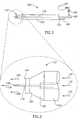
- Device 100includes a housing portion referenced 102 having a generally tubular configuration, and having proximal and distal ends, referenced generally 104 and 106 respectively.
- a gas inlet port referenced 108 and a liquid inlet port referenced 110are provided at proximal end 104, and a stream jet delivery nozzle arrangement referenced generally 112, is provided at distal end 106.
- FIG. 2there is additionally shown, in schematic form, a therapeutic liquid inlet port 109 connecting pressurized therapeutic liquid source 107 liquid via flow control device 105 to liquid inlet port 110 to allow production of a mixed flow of therapeutic liquid.
- a therapeutic liquid inlet port 109connecting pressurized therapeutic liquid source 107 liquid via flow control device 105 to liquid inlet port 110 to allow production of a mixed flow of therapeutic liquid.
- Nozzle arrangement 112includes a gas discharge nozzle referenced generally 114 and, disposed generally concentrically there-within, is a liquid discharge nozzle referenced 116.
- Liquid inlet port 110( Fig. 2 ) is connected in fluid flow communication with liquid discharge nozzle 116 by means of a liquid communication tube referenced 118, disposed generally concentrically within tubular housing portion 102 ( Figs. 2 and 3 ).
- Pressurized gas supplied from a pressurized gas sourceenters device 100 through gas inlet port 108 ( Fig. 2 ) and passes along and within tubular housing portion 102 as indicated by arrows 134, so as to discharge through gas discharge nozzle 114.
- Gas discharge nozzle 114is generally configured having, in flow succession, a converging portion referenced 120, a throat portion referenced 122 and a diverging discharge portion referenced 124.
- the pressurized gas discharging from nozzle 114, as indicated by arrows 126undergoes a rapid and substantial reduction in pressure to atmospheric pressure and a substantial acceleration to a high velocity, within the range of subsonic to supersonic velocity and specifically to a supersonic velocity.
- Gas discharge nozzle 114is configured such that the discharging gas has an average cone angle of less than 10 degrees; that is, providing a substantially parallel gas flow.
- the pressurized discharging gasemerges 126 from gas discharge nozzle 114 into the atmosphere, it undergoes a rapid drop in pressure to atmospheric pressure.
- the sudden pressure dropresults in a substantial acceleration of the velocity of the discharging gas flow that approximates or even exceeds the velocity of sound and results in the production of a shock wave.
- the effect of the shock waveis to atomize the therapeutic liquid discharging from liquid discharge nozzle 116 into the flow of gas as a stream of therapeutic liquid droplets 130, such that there is obtained a relatively narrow jet of therapeutic liquid droplets in a high velocity gas flow 126.
- the proportion of liquid flow to gas flowis extremely low due to the relatively high gas pressure of about 685 KPa (100 psi) and low liquid pressure of about 14 KPa (2 psi), as well as the relatively large internal diameter of gas discharge nozzle 114 (about 0.5 mm) compared to a small internal diameter (about 0.09 mm) of liquid discharge nozzle 116. Consequently, little liquid tends to accumulate at the site to be cleaned or treated. Furthermore, the relatively high gas flow has the effect of dispersing any accumulated liquid. When using a jet utilizing only liquid for cleansing, the liquid tends to accumulate on the tissue surface resulting in formation of a virtually stagnant liquid boundary layer close to and in contact with the surface, thereby reducing the effectiveness of cleansing.
- the very thin to negligible layer of liquid produced on the tissue surface by the present inventionallows more efficient dosage of additional therapeutic substances to the tissue surface, including the possibility of subcutaneous application of the therapeutic substances, as discussed hereinabove.
- FIG. 5there is seen a high velocity flow of therapeutic liquid droplets referenced 140 discharging, in a high velocity gas flow 126, from nozzle arrangement 112 against a tissue surface referenced 142 to be cleaned or treated.
- Device 100is held in the hand of a user by housing portion 102.
- FIG. 6there is seen a flow of therapeutic liquid droplets 140 discharging, in a high velocity gas flow 126, from nozzle arrangement 112 of device 100 into a periodontal pocket referenced 144 disposed between a gum referenced 146 and a tooth wall referenced 148.
- Device 100is held in the hand of a user by housing portion 102. This procedure is especially effective for cleansing periodontal pockets, subsequent to a dental descaling treatment, so as to remove plaque and calculus debris as well as bacteria and the toxins produced by the bacteria, which otherwise lead to mechanical irritation and inflammation of the gingiva.
- Device 100can further be used to apply desired dental therapeutic substances, such as antibiotics or anesthetics to the dental pocket.
- Nozzle arrangement 150is configured having multiple gas discharge nozzles referenced 152 and multiple therapeutic liquid discharge nozzles referenced 154 disposed generally concentrically within each gas nozzle 152 and projecting there-beyond.
- the therapeutic discharge nozzlesproject past the gas discharge nozzles in Figures 2-6 as well.
- Such a multiple nozzle arrangement 150facilitates expanding the rate of tissue cleaning, in the event that the system is used for this purpose.
- the present configurationsupports multiple therapeutic liquid flows, which may be individually controlled, as described hereinabove.
Landscapes
- Health & Medical Sciences (AREA)
- Animal Behavior & Ethology (AREA)
- Public Health (AREA)
- Anesthesiology (AREA)
- Biomedical Technology (AREA)
- Heart & Thoracic Surgery (AREA)
- Hematology (AREA)
- Engineering & Computer Science (AREA)
- Life Sciences & Earth Sciences (AREA)
- General Health & Medical Sciences (AREA)
- Vascular Medicine (AREA)
- Veterinary Medicine (AREA)
- Infusion, Injection, And Reservoir Apparatuses (AREA)
- Surgical Instruments (AREA)
- Acyclic And Carbocyclic Compounds In Medicinal Compositions (AREA)
- Medicines Containing Material From Animals Or Micro-Organisms (AREA)
- Dental Tools And Instruments Or Auxiliary Dental Instruments (AREA)
Abstract
Description
- The present invention relates, generally, to devices for administering therapeutic substances, and, more specifically, to devices for applying a high velocity therapeutic liquid-gas stream for administering such substances to the skin.
- It is known in the art to provide apparatus for dermal abrasion and the cleansing of exposed in vivo tissue. There are a multiplicity of applications to both humans and animals during surgical procedures where the removal from the tissue surface of solid contaminants, such as fibers, dust, sand particles, and the like, as well as organic matter, such as puss, fats, and others, is necessary.
- In addition, such cleansing is necessary in preparation prior to and/or subsequent to treatment such as applying therapeutic substances to the tissue. In dental conditions such as gingivitis which is caused by the long-term effects of plaque deposits, unremoved plaque mineralizes into a hard deposit called calculus (tartar) that becomes trapped at the base of the tooth which often becomes a host for bacteria. After descaling or scraping away the accumulated calculus, it is necessary to cleanse the area at the base of the tooth and the surrounding gum tissue, thereby removing calculus debris and the toxins produced by the bacteria.
- When a fluid stream is employed to irrigate a tissue surface, a boundary layer is formed which is characterized by having a fluid velocity which decreases sharply adjacent to the flow surface, and which is virtually zero at the tissue surface. As a result, those particles which are smaller than the thickness of the boundary layer of the fluid stream are often difficult or impossible to remove thereby. The smallest particles located in the boundary layer exhibit a drag resistance of a magnitude sufficient for these particles to remain attached to the surface and to resist being swept away by the fluid stream, even if this has an overall very high velocity.
- International Patent Application Publication Number
WO-A-2005/065032 , "A High Velocity Liquid-Gas Mist Tissue Abrasion Device" to the present inventor, provides a thorough overview of the prior art for tissue cleaning and abrasion. Disclosed therein is a device for tissue cleaning and abrasion employing a high-velocity liquid-gas streaming mist that produces a minimal to negligible thickness boundary layer. However, neither the device disclosed therein nor any of the prior art provides improved treatment by including the direct application of therapeutic substances to the tissue being treated. US6673081 to Tavger teaches an apparatus for dermal abrasion. The apparatus includesinter alia a container for a sterile liquid and a fluid delivery head for forming a liquid mist, the mist being ejected from the head at velocities that effect abrasion. The single liquid container does not allow for varying the concentration(s) of any substance(s) in the liquid which forms the mist.- The present invention aims to provide a system for improved treatment of tissue, in particular human scalp, by direct application thereto of desired therapeutic substances in the form of a stream of therapeutic droplets carried in a high velocity gas.
- A method of administering a therapeutic substance to tissue is described. The method includes the steps of:
- a) accelerating a flow of gas, which is one of a group including at least one of air, oxygen, nitrogen, and carbon dioxide, through at least one gas discharge nozzle so as to provide a gas discharge flow at an elevated velocity;
- b) introducing into the elevated velocity gas discharge flow at least one flow of therapeutic liquid, which is one of the group consisting of: saline solution and a solution comprising saline solution and at least one additional therapeutic substance, which may be a substance selected from a group which consists of: a medication, a nutrient, and a moisturizer, through at least one liquid discharge nozzle, thereby to fragment the at least one flow of therapeutic liquid into a stream of therapeutic droplets, and to accelerate the stream to an accelerated velocity similar to the velocity of the gas discharge flow; and
- c) applying the accelerated therapeutic droplet stream to a tissue mass desired for therapeutic treatment thereby.
- Further in accordance with a preferred embodiment of the invention, the step of applying is applying the accelerated therapeutic droplet stream to a human scalp in which hair may be present, which is desired for therapeutic treatment by the accelerated therapeutic droplet stream. Additionally, the accelerated therapeutic droplet stream may be applied to the tissue mass topically or subcutaneously. The step of applying the accelerated therapeutic droplet stream to a tissue mass may include holding in one hand a device for applying the accelerated therapeutic droplet stream. Additionally, the step of applying the accelerated therapeutic droplet stream to a tissue mass further includes cleansing the tissue mass thereby to remove contaminants from the tissue mass and dispersing accumulated liquid from the tissue mass by the flow of high velocity gas.
- In further accordance with a preferred embodiment of the invention, in the step of introducing, the at least one flow of therapeutic liquid is one flow of saline solution, and the step of introducing further includes the step of supplying, possibly at preselected times for preselected time intervals, to the flow of saline solution a predetermined flow of at least one additional therapeutic substance from the above-mentioned group, thereby producing a mixed flow of therapeutic liquid having a predetermined concentration of the at least one additional therapeutic substance.
- In accordance with an alternative preferred embodiment of the invention, in the step of introducing, the at least one flow of therapeutic liquid is at least two flows of therapeutic liquids, wherein a first flow of therapeutic liquid is a flow of saline solution and at least one additional flow of therapeutic liquid, which is possibly introduced at preselected times for preselected time intervals, is a predetermined flow of at least one additional therapeutic substance from the above-mentioned group, thereby producing a stream of therapeutic droplets containing a predetermined concentration of the at least one additional therapeutic substance.
- Additionally in accordance with a preferred embodiment of the invention, the step of accelerating a flow of gas includes accelerating the flow of gas to a velocity either in the range of sub-sonic to supersonic velocity or the range of sonic to supersonic velocity.
- Further in accordance with a preferred embodiment of the invention, the step of introducing into the elevated velocity gas discharge flow at least one flow of therapeutic liquid, includes the flow of gas entering the at least one gas discharge nozzle being at a pressure of a first magnitude, and the at least one gas discharge nozzle being operative to cause a pressure drop in the gas flow therethrough such that the pressure of the gas discharged from the at least one gas discharge nozzle is of a second magnitude, wherein the first magnitude is at least twice the second magnitude, thereby causing a shock wave in the gas and the at least one flow of liquid downstream of the at least one gas discharge nozzle and the at least one liquid discharge nozzle so as to cause atomizing of the therapeutic liquid discharged from the at least one liquid discharge nozzle into a high velocity stream of therapeutic droplets, thereby forming a stream of therapeutic droplets suspended in the flow of discharged high velocity gas.
- A device for administering a therapeutic substance to tissue is described. The device includes:
- a) a gas inlet port connected to a pressurized gas source at a pressure in the range of about 275 to 1035 KPa (40 to 150 psi), and including at least one gas selected from: air, oxygen, carbon dioxide and nitrogen;
- b) at least one therapeutic liquid inlet port, each connected to a pressurized therapeutic liquid source at a pressure in the range of about 7 to 35 KPa (1 to 5 psi), and wherein the therapeutic liquid is one of the group which consists of: saline solution and a solution comprising saline solution and at least one additional therapeutic substance which is a substance selected from a group which consists of: a medication, a nutrient, and a moisturizer; and operative to supply therapeutic liquid at preselected times for preselected intervals; and
- c) a stream jet delivery nozzle arrangement including;
- i) at least one gas discharge nozzle arranged to receive a flow of pressurized gas from the gas inlet port and configured to accelerate the flow of gas so as to discharge it at an elevated velocity in the range of sub-sonic to supersonic velocity; and
- ii) at least one liquid discharge nozzle arranged to receive a flow of therapeutic liquid from the at least one therapeutic liquid inlet port and operative to discharge the flow of therapeutic liquid into the elevated velocity flow of gas, thereby to similarly accelerate the velocity of the discharged therapeutic liquid as a therapeutic stream of accelerated therapeutic droplets and to discharge the stream of accelerated therapeutic droplets towards a tissue mass desired for therapeutic treatment by the therapeutic droplets.
- Further in accordance with a preferred embodiment of the invention, the tissue mass desired for therapeutic treatment is a human scalp in which hair may be present.
- In accordance with an alternative preferred embodiment of the invention, the stream jet delivery nozzle arrangement may include at least two gas discharge nozzles and at least two liquid discharge nozzles.
- Additionally, in accordance with a preferred embodiment of the invention, the at least one liquid discharge nozzle is disposed substantially concentric and within the at least one gas discharge nozzle and the at least one gas discharge nozzle is a device configured to have a converging portion, a throat portion and a diverging portion. Further, the device is configured to be used while being held in one hand.
- Further in accordance with a preferred embodiment of the invention, the flow of gas entering the at least one gas discharge nozzle is at a pressure of a first magnitude, and the at least one gas discharge nozzle is operative to cause a pressure drop in the gas flow therethrough such that the pressure of the gas discharged from the at least one gas discharge nozzle is of a second magnitude, wherein the first magnitude is at least twice the second magnitude, so as to cause a shock wave in the gas and the at least one flow of liquid downstream of the at least one gas discharge nozzle and the at least one liquid discharge nozzle so as to cause atomizing of the therapeutic liquid discharged from the at least one liquid discharge nozzle into a high velocity stream of therapeutic droplets, thereby to form a stream of therapeutic droplets suspended in the flow of discharged high velocity gas.
- There is provided, in accordance with a preferred embodiment of the invention, a system for administering a therapeutic substance to tissue, including:
- a) a pressurized gas source;
- b) at least one pressurized therapeutic liquid source; and
- c) a device as described hereinabove.
- The present invention will be more fully understood and its features and advantages will become apparent to those skilled in the art by reference to the ensuing description, taken in conjunction with the accompanying drawings, in which:
Figure 1 is a perspective view of a device for administering therapeutic substances to tissue, constructed and operative in accordance with a preferred embodiment of the present invention;Figure 2 is a schematic side view of the device ofFig. 1 ;Figure 3 and4 are enlarged schematic and graphical representations, respectively, of a delivery nozzle arrangement of the device seen inFigures 1 and2 ;Figure 5 is a schematic view of a flow of stream droplets discharging from the delivery nozzle arrangement as seen inFigure 4 against a surface to which therapeutic substances are to be administered;Figure 6 is a schematic view of a flow of stream droplets discharging from the delivery nozzle arrangement seen inFigure 4 , into a periodontal pocket;Figure 7 is a schematic view of a nozzle arrangement, constructed and operative in accordance with an alternative embodiment of the present invention, having multiple gas and liquid discharge nozzles; andFigure 8 is a block diagram of a system for administering therapeutic substances to tissue, in accordance with preferred embodiments of the present invention.- The present invention relates to a device for administering therapeutic substances to tissue by directing thereat a liquid-gas stream of droplets consisting of one or more therapeutic liquids at a high velocity generally within the range of sub-sonic to super-sonic. To achieve this, gas is discharged from a converging-diverging gas nozzle configured to accelerate the flow of gas so as to discharge it at an elevated velocity. A low rate of flow of therapeutic liquid is discharged into the elevated velocity flow of gas, thereby to similarly accelerate the velocity of the discharged therapeutic liquid as a therapeutic stream of accelerated droplets. The volumetric rate of flow of therapeutic liquid from the device is relatively low, thereby essentially preventing the formation of a virtually stagnant liquid boundary layer on the surface of the tissue to which therapeutic substances are to be administered.
- When the therapeutic liquid administered by the present invention is saline solution, the invention can first be employed to clean a tissue surface, as described in International Patent Application Publication Number
WO-A-2005/065032 , "A High Velocity Liquid-Gas Mist Tissue Abrasion Device" to the present inventor, prior to administering additional therapeutic substances, such as medications, nutrients, or moisturizers; or colorants, any of which may be in liquid or soluble powder form. This allows more efficient dosing of the subsequent therapeutic substances, since, as will be appreciated by persons skilled in the art, the substances removed by cleaning would be likely, if left in place, to impede application and/or absorption of the desired therapeutic substances to the tissue desired for therapeutic treatment thereby. Included in the present invention are fluid flow control mechanisms known in the art operative to introduce into the device of the present invention a mixed flow of saline solution and other therapeutic substances, which may be in liquid or emulsion form, of a desired concentration therein which can further be controlled to only produce the mixed flow at specified times and for specified intervals. The device of the present invention would then accordingly produce a mixed therapeutic stream as desired and needed. Thus, as described above a tissue surface could first be cleaned by saline solution and then dosed therapeutically by a medication solution when it is ready to optimally receive the dosage. In an alternative embodiment of the present invention, instead of one mixed flow as mentioned hereinabove, the present invention further includes fluid flow control mechanisms known in the art operative to produce a number of therapeutic liquid flows for discharge into the elevated velocity flow of gas, which also may be turned on and off at specified times and for specified intervals. This arrangement also produces a mixed therapeutic stream as desired and needed. - For example, the present invention can be used to treat a human scalp, even where hair is present. First, the device produces an accelerated saline stream used to clean the scalp of extraneous material, excess oils, and dead epidermal tissue such as is known to produce dandruff. Then, a moisturizing, nutrient, anti-dandruff, or anti-hair loss, or other desired therapeutic substance is included in the accelerated stream to apply the desired therapeutic treatment to the scalp.
- It should further be noted that the present invention is capable of applying the therapeutic substance to the desired tissue both topically and subcutaneously. Investigations employing prototype versions of the present invention have shown that the accelerated therapeutic stream produced thereby will, for suitable droplet flow velocities and length of time of exposure of the tissue to the droplet flow, penetrate the tissue surface. This capacity of non-invasive subcutaneous treatment and dosage is a further advantage of the present invention.
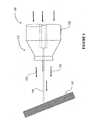
- Referring now to
Figure 8 , there is shown a block diagram of a system, generally referred to as 500, for applying a high velocity liquid-gas therapeutic stream to tissue for therapeutic treatment thereof.System 500 employs astream generating device 510 similar to that disclosed in International Patent Application Publication NumberWO-A-2005/065032 , "A High Velocity Liquid-Gas Mist Tissue Abrasion Device" to the present inventor, which is fed by highpressure gas supply 520 and high pressureliquid supply 530 and produces a high-velocity liquid-gas mist stream 550 suitable for tissue abrasion as described therein. The present invention further includes a supply oftherapeutic substance 540, which may be in liquid or soluble powder form, that is introduced toliquid supply 530 so that the resulting high- velocity liquid-gas stream 550 includes the therapeutic substance which is thus applied to the tissue mass exposed tostream 550. Alternatively 575, the therapeutic substance is introduced directly intostream generating device 510 either in addition to (neutral)liquid supply 530 or whenliquid supply 530 is turned off, thereby producing the desired high- velocity liquid-gas stream 550 which includes a predetermined concentration of the therapeutic substance. - With reference to
Figures 1 and2 , there is seen, according to a preferred embodiment of the present invention, a device referenced generally 100 for applying a high velocity liquid-gas therapeutic stream to tissue for therapeutic treatment thereof. Alternatively, the velocity of the stream may be regulated so as to merely provide cleansing of the tissue.Device 100 includes a housing portion referenced 102 having a generally tubular configuration, and having proximal and distal ends, referenced generally 104 and 106 respectively. A gas inlet port referenced 108 and a liquid inlet port referenced 110 are provided atproximal end 104, and a stream jet delivery nozzle arrangement referenced generally 112, is provided atdistal end 106. InFigure 2 , there is additionally shown, in schematic form, a therapeuticliquid inlet port 109 connecting pressurized therapeuticliquid source 107 liquid viaflow control device 105 toliquid inlet port 110 to allow production of a mixed flow of therapeutic liquid. It should be noted that the present arrangement producing one mixed therapeutic liquid flow is only shown by way of example, and that multiple therapeutic liquid flows, as well as control of the time of application of different therapeutic liquid flows are also included in the present invention as discussed hereinabove. - Referring now to
Figures 3 and4 in conjunction withFigure 2 , there are seen schematic and graphical cross-sectional views ofnozzle arrangement 112 ofdevice 100.Nozzle arrangement 112 includes a gas discharge nozzle referenced generally 114 and, disposed generally concentrically there-within, is a liquid discharge nozzle referenced 116. Liquid inlet port 110 (Fig. 2 ) is connected in fluid flow communication withliquid discharge nozzle 116 by means of a liquid communication tube referenced 118, disposed generally concentrically within tubular housing portion 102 (Figs. 2 and 3 ). - Pressurized gas supplied from a pressurized gas source (not shown) enters
device 100 through gas inlet port 108 (Fig. 2 ) and passes along and withintubular housing portion 102 as indicated byarrows 134, so as to discharge throughgas discharge nozzle 114.Gas discharge nozzle 114 is generally configured having, in flow succession, a converging portion referenced 120, a throat portion referenced 122 and a diverging discharge portion referenced 124. The pressurized gas discharging fromnozzle 114, as indicated byarrows 126, undergoes a rapid and substantial reduction in pressure to atmospheric pressure and a substantial acceleration to a high velocity, within the range of subsonic to supersonic velocity and specifically to a supersonic velocity.Gas discharge nozzle 114 is configured such that the discharging gas has an average cone angle of less than 10 degrees; that is, providing a substantially parallel gas flow. - Liquid, including a desired concentration of therapeutic substances, from one or more pressurized therapeutic liquid sources (not shown) enters
device 100 through liquid inlet port 110 (Fig. 2 ) and passes, as indicated byarrow 132, through liquid communication tube 118 (Figs. 2 and4 ). In turn, atdistal end 106, therapeutic liquid is discharged through an opening referenced 128 in the distal end ofliquid discharge nozzle 116 into the dischargingflow 126 of gas, the therapeutic liquid flow being indicated byarrow 130. - It will be appreciated by persons skilled in the art that, as the pressurized discharging gas emerges 126 from
gas discharge nozzle 114 into the atmosphere, it undergoes a rapid drop in pressure to atmospheric pressure. The sudden pressure drop results in a substantial acceleration of the velocity of the discharging gas flow that approximates or even exceeds the velocity of sound and results in the production of a shock wave. The effect of the shock wave is to atomize the therapeutic liquid discharging fromliquid discharge nozzle 116 into the flow of gas as a stream of therapeuticliquid droplets 130, such that there is obtained a relatively narrow jet of therapeutic liquid droplets in a highvelocity gas flow 126. - Further, by way of example, the proportion of liquid flow to gas flow is extremely low due to the relatively high gas pressure of about 685 KPa (100 psi) and low liquid pressure of about 14 KPa (2 psi), as well as the relatively large internal diameter of gas discharge nozzle 114 (about 0.5 mm) compared to a small internal diameter (about 0.09 mm) of
liquid discharge nozzle 116. Consequently, little liquid tends to accumulate at the site to be cleaned or treated. Furthermore, the relatively high gas flow has the effect of dispersing any accumulated liquid. When using a jet utilizing only liquid for cleansing, the liquid tends to accumulate on the tissue surface resulting in formation of a virtually stagnant liquid boundary layer close to and in contact with the surface, thereby reducing the effectiveness of cleansing. The very thin to negligible layer of liquid produced on the tissue surface by the present invention allows more efficient dosage of additional therapeutic substances to the tissue surface, including the possibility of subcutaneous application of the therapeutic substances, as discussed hereinabove. - Referring now to
Figure 5 , there is seen a high velocity flow of therapeutic liquid droplets referenced 140 discharging, in a highvelocity gas flow 126, fromnozzle arrangement 112 against a tissue surface referenced 142 to be cleaned or treated.Device 100 is held in the hand of a user byhousing portion 102. - Referring now to
Figure 6 , there is seen a flow of therapeuticliquid droplets 140 discharging, in a highvelocity gas flow 126, fromnozzle arrangement 112 ofdevice 100 into a periodontal pocket referenced 144 disposed between a gum referenced 146 and a tooth wall referenced 148.Device 100 is held in the hand of a user byhousing portion 102. This procedure is especially effective for cleansing periodontal pockets, subsequent to a dental descaling treatment, so as to remove plaque and calculus debris as well as bacteria and the toxins produced by the bacteria, which otherwise lead to mechanical irritation and inflammation of the gingiva.Device 100 can further be used to apply desired dental therapeutic substances, such as antibiotics or anesthetics to the dental pocket. - Referring now to
Figure 7 , there is seen, according to an alternative embodiment of the present invention, a cross-sectional view of a device (not shown) having ahousing portion 102 and a multiple nozzle arrangement referenced generally 150.Nozzle arrangement 150 is configured having multiple gas discharge nozzles referenced 152 and multiple therapeutic liquid discharge nozzles referenced 154 disposed generally concentrically within eachgas nozzle 152 and projecting there-beyond. The therapeutic discharge nozzles project past the gas discharge nozzles inFigures 2-6 as well. Such amultiple nozzle arrangement 150 facilitates expanding the rate of tissue cleaning, in the event that the system is used for this purpose. Additionally, the present configuration supports multiple therapeutic liquid flows, which may be individually controlled, as described hereinabove. - It will be appreciated by persons skilled in the art that the present invention is not limited by the drawings and description hereinabove presented. Rather, the invention is defined by the claims that follow.
Claims (13)
- A system (500) for administering a therapeutic substance to tissue, which includes:a) a pressurized gas source (520);b) a pressurized liquid source (530);c) at least one pressurized therapeutic liquid source (107, 540); andd) a device (100, 510) which includes:i) a gas inlet port (108) connected to said pressurized gas source (520);ii) a liquid inlet port (110) through which a pressurized liquid moves from said pressurized liquid source (530);iii) at least one therapeutic liquid inlet port (109), each port (109) connected to at least one of said at least one pressurized therapeutic liquid source (107, 540) controllable by a control device (105) so that said at least one pressurized therapeutic liquid source (107, 540) is operative to supply therapeutic liquid at preselected times for preselected intervals, thereby to control the timing and dosage of the therapeutic liquid; andiv) a stream jet delivery nozzle (112) arrangement including;1) at least one gas discharge nozzle (114, 152) arranged to receive a flow of pressurized gas from said gas inlet port (108) and configured to accelerate the flow of gas so as to discharge it at an elevated velocity; and2) at least one liquid discharge nozzle (116, 154) arranged to receive a flow of therapeutic liquid and operative to discharge the flow of therapeutic liquid into the elevated velocity flow of gas, thereby to similarly accelerate the velocity of the discharged therapeutic liquid as a therapeutic stream of accelerated therapeutic droplets and to discharge said stream of accelerated therapeutic droplets towards a tissue mass desired for therapeutic treatment by said therapeutic droplets.
- A system (500) according to claim 1, wherein the tissue mass desired for therapeutic treatment is a human scalp.
- A system (500) according to claim 1 or 2, wherein said at least one therapeutic liquid includes a liquid selected from a group which consists of:saline solution, and a solution comprising saline solution and at least one additional therapeutic substance and wherein said therapeutic substance is a substance selected from a group which consists of: a medication, a nutrient, and a moisturizer.
- A system (500) according to any preceding claim, wherein the gas discharged from said at least one gas discharge nozzle (114, 152) is accelerated to a velocity in the range of sub-sonic to supersonic velocity.
- A system (500) according to any preceding claim, wherein said stream jet delivery nozzle (112) arrangement includes at least two gas discharge nozzles (114, 152).
- A system (500) according to any preceding claim, wherein said stream jet delivery nozzle (112) arrangement includes at least two liquid discharge nozzles (154).
- A system (500) according to any preceding claim, wherein said at least one liquid discharge nozzle (116, 154) is disposed substantially concentric and within said at least one gas discharge nozzle (114, 152).
- A system (500) according to any preceding claim, wherein said at least one gas discharge nozzle (114, 152) is a device configured to have a converging portion (120), a throat portion (122) and a diverging portion (124).
- A system (500) according to any preceding claim, wherein the flow of gas entering said at least one gas discharge nozzle (114, 152) is at a pressure of a first magnitude, and said at least one gas discharge nozzle (114, 152) is operative to cause a pressure drop in the gas flow therethrough such that the pressure of the gas discharged from said at least one gas discharge nozzle (114, 152) is of a second magnitude, wherein the first magnitude is at least twice the second magnitude, so as to cause a shock wave in the gas and the at least one flow of liquid downstream of said at least one gas discharge nozzle (114, 152) and said at least one liquid discharge nozzle (116, 154) so as to cause atomizing of the therapeutic liquid discharged from said at least one liquid discharge nozzle (116, 154) into a high velocity stream of therapeutic droplets (130, 550), thereby to form a stream of therapeutic droplets suspended in the flow of discharged high velocity gas.
- A system (500) according to any preceding claim, wherein the therapeutic liquid enters said at least one liquid discharge nozzle (116, 154) via said liquid inlet port (110) after entering said liquid inlet port (110) through said therapeutic liquid inlet port (109).
- A system (500) according to any one of claims 1 to 9, wherein the therapeutic liquid enters said at least one liquid discharge nozzle (116, 154) directly from said pressurized therapeutic liquid source (107, 540).
- A system (500) according to any one of claims 1 to 10, wherein the therapeutic liquid in said pressurized therapeutic liquid source (107, 540) is a soluble powder substance soluble in the liquid passing through said liquid inlet port (110) from said pressurized liquid source (530) to said stream jet delivery nozzle (112).
- A system (500) according to any preceding claim, wherein said control device (105) is a plurality of fluid flow mechanisms which produce a plurality of therapeutic liquid flows.
Applications Claiming Priority (3)
| Application Number | Priority Date | Filing Date | Title |
|---|---|---|---|
| US68102205P | 2005-05-16 | 2005-05-16 | |
| IL168616AIL168616A (en) | 2005-05-16 | 2005-05-16 | High velocity liquid-gas stream device for administering therapeutic substances |
| PCT/IL2006/000557WO2006123326A2 (en) | 2005-05-16 | 2006-05-11 | A high velocity liquid-gas stream device for administering therapeutic substances |
Publications (3)
| Publication Number | Publication Date |
|---|---|
| EP1883447A2 EP1883447A2 (en) | 2008-02-06 |
| EP1883447A4 EP1883447A4 (en) | 2008-07-30 |
| EP1883447B1true EP1883447B1 (en) | 2009-09-02 |
Family
ID=46829921
Family Applications (1)
| Application Number | Title | Priority Date | Filing Date |
|---|---|---|---|
| EP06728345AActiveEP1883447B1 (en) | 2005-05-16 | 2006-05-11 | A high velocity liquid-gas stream device for administering therapeutic substances |
Country Status (7)
| Country | Link |
|---|---|
| US (1) | US20090036824A1 (en) |
| EP (1) | EP1883447B1 (en) |
| AT (1) | ATE441450T1 (en) |
| DE (1) | DE602006008926D1 (en) |
| ES (1) | ES2332941T3 (en) |
| IL (1) | IL168616A (en) |
| WO (1) | WO2006123326A2 (en) |
Cited By (12)
| Publication number | Priority date | Publication date | Assignee | Title |
|---|---|---|---|---|
| US11794029B2 (en) | 2016-07-01 | 2023-10-24 | Btl Medical Solutions A.S. | Aesthetic method of biological structure treatment by magnetic field |
| US11806528B2 (en) | 2020-05-04 | 2023-11-07 | Btl Healthcare Technologies A.S. | Device and method for unattended treatment of a patient |
| US11826565B2 (en) | 2020-05-04 | 2023-11-28 | Btl Healthcare Technologies A.S. | Device and method for unattended treatment of a patient |
| US11878162B2 (en) | 2016-05-23 | 2024-01-23 | Btl Healthcare Technologies A.S. | Systems and methods for tissue treatment |
| US11883643B2 (en) | 2016-05-03 | 2024-01-30 | Btl Healthcare Technologies A.S. | Systems and methods for treatment of a patient including RF and electrical energy |
| US11896816B2 (en) | 2021-11-03 | 2024-02-13 | Btl Healthcare Technologies A.S. | Device and method for unattended treatment of a patient |
| US12064163B2 (en) | 2021-10-13 | 2024-08-20 | Btl Medical Solutions A.S. | Methods and devices for aesthetic treatment of biological structures by radiofrequency and magnetic energy |
| US12076576B2 (en) | 2019-04-11 | 2024-09-03 | Btl Medical Solutions A.S. | Methods and devices for aesthetic treatment of biological structures by radiofrequency and magnetic energy |
| US12109426B2 (en) | 2016-05-10 | 2024-10-08 | Btl Medical Solutions A.S. | Aesthetic method of biological structure treatment by magnetic field |
| US12109427B2 (en) | 2016-07-01 | 2024-10-08 | Btl Medical Solutions A.S. | Aesthetic method of biological structure treatment by magnetic field |
| US12156689B2 (en) | 2019-04-11 | 2024-12-03 | Btl Medical Solutions A.S. | Methods and devices for aesthetic treatment of biological structures by radiofrequency and magnetic energy |
| US12274494B2 (en) | 2016-08-16 | 2025-04-15 | Btl Healthcare Technologies A.S. | Treatment device |
Families Citing this family (7)
| Publication number | Priority date | Publication date | Assignee | Title |
|---|---|---|---|---|
| US20130172680A1 (en)* | 2010-10-22 | 2013-07-04 | Med-Jet Ltd. | Endoscopic method and device |
| US9233207B2 (en) | 2011-02-22 | 2016-01-12 | Tavtech Ltd. | Device for administering therapeutic substances using a high velocity liquid-gas stream |
| WO2013190537A1 (en)* | 2012-06-18 | 2013-12-27 | Michael Tavger | Method and system for delivering solution into the pores of recipient human skin |
| CN211024753U (en)* | 2018-09-02 | 2020-07-17 | 塔夫泰什有限公司 | Device, system and air flow shield generator for applying therapeutic substances to tissue |
| EP3714926A1 (en)* | 2019-03-28 | 2020-09-30 | Erbe Elektromedizin GmbH | Instrument, instrument head, application system and method |
| CN112682010A (en)* | 2020-12-28 | 2021-04-20 | 中国石油集团渤海钻探工程有限公司 | Supersonic atomizing throttling device with self-excited oscillation mode |
| CN116899096A (en)* | 2023-08-28 | 2023-10-20 | 深圳市诺普恩科技有限公司 | Hand-held type water light appearance |
Family Cites Families (7)
| Publication number | Priority date | Publication date | Assignee | Title |
|---|---|---|---|---|
| US5022414A (en)* | 1979-12-13 | 1991-06-11 | Joseph J. Berke | Tissue separator method |
| IL122016A (en)* | 1997-10-22 | 2001-09-13 | Tav Tech Ltd | Apparatus for dermal abrasion |
| WO1999037229A1 (en)* | 1998-01-26 | 1999-07-29 | Very Inventive Physicians, Inc. | Epidermal and dermal skin removal apparatus |
| US6306119B1 (en)* | 1999-01-20 | 2001-10-23 | Pearl Technology Holdings, Llc | Skin resurfacing and treatment using biocompatible materials |
| US6168577B1 (en)* | 1999-01-25 | 2001-01-02 | Cardiothoracic Systems, Inc. | Directed stream blower for clearing a surgical site |
| FR2834442B1 (en)* | 2002-01-07 | 2004-10-08 | Saphir Medical | APPARATUS FOR MICRODOSE INJECTION OF AN ACTIVE PRODUCT BY PRESSURE WORKING LIQUID JETS AND METHOD FOR GENERATING A SEQUENCE OF LIQUID JETS USING THE SAME |
| IL159783A (en)* | 2004-01-08 | 2009-06-15 | Tavtech Ltd | High velocity liquid-gas mist tissue abrasion device |
- 2005
- 2005-05-16ILIL168616Apatent/IL168616A/enactiveIP Right Grant
- 2006
- 2006-05-11ATAT06728345Tpatent/ATE441450T1/ennot_activeIP Right Cessation
- 2006-05-11EPEP06728345Apatent/EP1883447B1/enactiveActive
- 2006-05-11DEDE602006008926Tpatent/DE602006008926D1/enactiveActive
- 2006-05-11ESES06728345Tpatent/ES2332941T3/enactiveActive
- 2006-05-11USUS11/920,412patent/US20090036824A1/ennot_activeAbandoned
- 2006-05-11WOPCT/IL2006/000557patent/WO2006123326A2/ennot_activeApplication Discontinuation
Cited By (20)
| Publication number | Priority date | Publication date | Assignee | Title |
|---|---|---|---|---|
| US11883643B2 (en) | 2016-05-03 | 2024-01-30 | Btl Healthcare Technologies A.S. | Systems and methods for treatment of a patient including RF and electrical energy |
| US12151120B2 (en) | 2016-05-10 | 2024-11-26 | Btl Medical Solutions A.S. | Aesthetic method of biological structure treatment by magnetic field |
| US12109426B2 (en) | 2016-05-10 | 2024-10-08 | Btl Medical Solutions A.S. | Aesthetic method of biological structure treatment by magnetic field |
| US11878162B2 (en) | 2016-05-23 | 2024-01-23 | Btl Healthcare Technologies A.S. | Systems and methods for tissue treatment |
| US11896821B2 (en) | 2016-05-23 | 2024-02-13 | Btl Healthcare Technologies A.S. | Systems and methods for tissue treatment |
| US11794029B2 (en) | 2016-07-01 | 2023-10-24 | Btl Medical Solutions A.S. | Aesthetic method of biological structure treatment by magnetic field |
| US12109427B2 (en) | 2016-07-01 | 2024-10-08 | Btl Medical Solutions A.S. | Aesthetic method of biological structure treatment by magnetic field |
| US12274494B2 (en) | 2016-08-16 | 2025-04-15 | Btl Healthcare Technologies A.S. | Treatment device |
| US12076576B2 (en) | 2019-04-11 | 2024-09-03 | Btl Medical Solutions A.S. | Methods and devices for aesthetic treatment of biological structures by radiofrequency and magnetic energy |
| US12156689B2 (en) | 2019-04-11 | 2024-12-03 | Btl Medical Solutions A.S. | Methods and devices for aesthetic treatment of biological structures by radiofrequency and magnetic energy |
| US11878167B2 (en) | 2020-05-04 | 2024-01-23 | Btl Healthcare Technologies A.S. | Device and method for unattended treatment of a patient |
| US12029905B2 (en) | 2020-05-04 | 2024-07-09 | Btl Healthcare Technologies A.S. | Device and method for unattended treatment of a patient |
| US11826565B2 (en) | 2020-05-04 | 2023-11-28 | Btl Healthcare Technologies A.S. | Device and method for unattended treatment of a patient |
| US11813451B2 (en) | 2020-05-04 | 2023-11-14 | Btl Healthcare Technologies A.S. | Device and method for unattended treatment of a patient |
| US11806528B2 (en) | 2020-05-04 | 2023-11-07 | Btl Healthcare Technologies A.S. | Device and method for unattended treatment of a patient |
| US12311170B2 (en) | 2020-05-04 | 2025-05-27 | Btl Healthcare Technologies A.S. | Device and method for unattended treatment of a patient |
| US12427307B2 (en) | 2020-05-04 | 2025-09-30 | Btl Healthcare Technologies A.S. | Device and method for unattended treatment of a patient |
| US12064163B2 (en) | 2021-10-13 | 2024-08-20 | Btl Medical Solutions A.S. | Methods and devices for aesthetic treatment of biological structures by radiofrequency and magnetic energy |
| US11896816B2 (en) | 2021-11-03 | 2024-02-13 | Btl Healthcare Technologies A.S. | Device and method for unattended treatment of a patient |
| US12115365B2 (en) | 2021-11-03 | 2024-10-15 | Btl Healthcare Technologies A.S. | Device and method for unattended treatment of a patient |
Also Published As
| Publication number | Publication date |
|---|---|
| IL168616A (en) | 2010-12-30 |
| DE602006008926D1 (en) | 2009-10-15 |
| EP1883447A2 (en) | 2008-02-06 |
| EP1883447A4 (en) | 2008-07-30 |
| WO2006123326A3 (en) | 2007-11-15 |
| ES2332941T3 (en) | 2010-02-15 |
| ATE441450T1 (en) | 2009-09-15 |
| WO2006123326A2 (en) | 2006-11-23 |
| US20090036824A1 (en) | 2009-02-05 |
Similar Documents
| Publication | Publication Date | Title |
|---|---|---|
| EP1883447B1 (en) | A high velocity liquid-gas stream device for administering therapeutic substances | |
| US9233207B2 (en) | Device for administering therapeutic substances using a high velocity liquid-gas stream | |
| EP1904150B1 (en) | A high velocity liquid-gas mist tissue abrasion device | |
| CN210250131U (en) | Device for applying liquid therapeutic substances to tissue | |
| US20210299420A1 (en) | A device with shield for administering therapeutic substances using a high velocity liquid-gas stream | |
| RU2211676C2 (en) | Method and device for treating skin by rubbing | |
| US6162232A (en) | Instruments and techniques for high-velocity fluid abrasion of epidermal layers with skin cooling | |
| EP2815777B1 (en) | Water jet spray nozzle, water jet spray device, gastrointestinal tract cleaning device, and gastric wall cleaning device | |
| JP2010005411A (en) | Needleless syringe | |
| JPS6467272A (en) | Spray nozzle, sprayer and method for use thereof | |
| AU2003218570A1 (en) | Needleless syringe for the subcutaneous injection of droplets of liquid substances | |
| US5860942A (en) | Dental water irrigator employing hydrodynamic cavitation | |
| JP2001507948A (en) | Apparatus and method for cleaning tissue | |
| WO2016013256A1 (en) | Device for generating fine mists for washing use, device for washing oral cavity, nozzle, method for washing oral cavity, and method for generating fine mists for washing use using device for generating fine mists for washing use | |
| WO2002053014A3 (en) | Apparatus and method for cutting and removal of biological tissue by pressurized propulsion of ice particles | |
| CN111672017A (en) | Porous nozzle | |
| RU72843U1 (en) | SPRAY NOZZLE NOZZLE FOR SPRAYING HARD TOOTH FABRICS WITH A SPIRAL CHANNEL | |
| CN117018416B (en) | Non-invasive deep-dive equipment based on high-pressure pure oxygen | |
| JP2002535067A (en) | Method and apparatus for treating tissue with fluid jet | |
| RU70452U1 (en) | SPRAY NOZZLE NOZZLE FOR PROCESSING HARD TOOTH TISSUES WITH EXPLOSION OF THE JET CHANNEL CHANNEL IN ELLIPSE | |
| JP2005527259A (en) | Method for the treatment of the skin area of a human subject, in particular a cosmetic treatment by the transepidermal route using the release of liquid under pressure |
Legal Events
| Date | Code | Title | Description |
|---|---|---|---|
| PUAI | Public reference made under article 153(3) epc to a published international application that has entered the european phase | Free format text:ORIGINAL CODE: 0009012 | |
| 17P | Request for examination filed | Effective date:20071203 | |
| AK | Designated contracting states | Kind code of ref document:A2 Designated state(s):AT BE BG CH CY CZ DE DK EE ES FI FR GB GR HU IE IS IT LI LT LU LV MC NL PL PT RO SE SI SK TR | |
| AX | Request for extension of the european patent | Extension state:AL BA HR MK YU | |
| A4 | Supplementary search report drawn up and despatched | Effective date:20080702 | |
| DAX | Request for extension of the european patent (deleted) | ||
| 17Q | First examination report despatched | Effective date:20080916 | |
| GRAP | Despatch of communication of intention to grant a patent | Free format text:ORIGINAL CODE: EPIDOSNIGR1 | |
| GRAS | Grant fee paid | Free format text:ORIGINAL CODE: EPIDOSNIGR3 | |
| GRAA | (expected) grant | Free format text:ORIGINAL CODE: 0009210 | |
| AK | Designated contracting states | Kind code of ref document:B1 Designated state(s):AT BE BG CH CY CZ DE DK EE ES FI FR GB GR HU IE IS IT LI LT LU LV MC NL PL PT RO SE SI SK TR | |
| REG | Reference to a national code | Ref country code:CH Ref legal event code:EP | |
| REG | Reference to a national code | Ref country code:IE Ref legal event code:FG4D | |
| REF | Corresponds to: | Ref document number:602006008926 Country of ref document:DE Date of ref document:20091015 Kind code of ref document:P | |
| PG25 | Lapsed in a contracting state [announced via postgrant information from national office to epo] | Ref country code:SE Free format text:LAPSE BECAUSE OF FAILURE TO SUBMIT A TRANSLATION OF THE DESCRIPTION OR TO PAY THE FEE WITHIN THE PRESCRIBED TIME-LIMIT Effective date:20090902 Ref country code:FI Free format text:LAPSE BECAUSE OF FAILURE TO SUBMIT A TRANSLATION OF THE DESCRIPTION OR TO PAY THE FEE WITHIN THE PRESCRIBED TIME-LIMIT Effective date:20090902 Ref country code:LT Free format text:LAPSE BECAUSE OF FAILURE TO SUBMIT A TRANSLATION OF THE DESCRIPTION OR TO PAY THE FEE WITHIN THE PRESCRIBED TIME-LIMIT Effective date:20090902 | |
| REG | Reference to a national code | Ref country code:ES Ref legal event code:FG2A Ref document number:2332941 Country of ref document:ES Kind code of ref document:T3 | |
| LTIE | Lt: invalidation of european patent or patent extension | Effective date:20090902 | |
| PG25 | Lapsed in a contracting state [announced via postgrant information from national office to epo] | Ref country code:PL Free format text:LAPSE BECAUSE OF FAILURE TO SUBMIT A TRANSLATION OF THE DESCRIPTION OR TO PAY THE FEE WITHIN THE PRESCRIBED TIME-LIMIT Effective date:20090902 Ref country code:SI Free format text:LAPSE BECAUSE OF FAILURE TO SUBMIT A TRANSLATION OF THE DESCRIPTION OR TO PAY THE FEE WITHIN THE PRESCRIBED TIME-LIMIT Effective date:20090902 Ref country code:LV Free format text:LAPSE BECAUSE OF FAILURE TO SUBMIT A TRANSLATION OF THE DESCRIPTION OR TO PAY THE FEE WITHIN THE PRESCRIBED TIME-LIMIT Effective date:20090902 | |
| PG25 | Lapsed in a contracting state [announced via postgrant information from national office to epo] | Ref country code:CY Free format text:LAPSE BECAUSE OF FAILURE TO SUBMIT A TRANSLATION OF THE DESCRIPTION OR TO PAY THE FEE WITHIN THE PRESCRIBED TIME-LIMIT Effective date:20090902 | |
| PG25 | Lapsed in a contracting state [announced via postgrant information from national office to epo] | Ref country code:IS Free format text:LAPSE BECAUSE OF FAILURE TO SUBMIT A TRANSLATION OF THE DESCRIPTION OR TO PAY THE FEE WITHIN THE PRESCRIBED TIME-LIMIT Effective date:20100102 Ref country code:PT Free format text:LAPSE BECAUSE OF FAILURE TO SUBMIT A TRANSLATION OF THE DESCRIPTION OR TO PAY THE FEE WITHIN THE PRESCRIBED TIME-LIMIT Effective date:20100104 Ref country code:EE Free format text:LAPSE BECAUSE OF FAILURE TO SUBMIT A TRANSLATION OF THE DESCRIPTION OR TO PAY THE FEE WITHIN THE PRESCRIBED TIME-LIMIT Effective date:20090902 Ref country code:RO Free format text:LAPSE BECAUSE OF FAILURE TO SUBMIT A TRANSLATION OF THE DESCRIPTION OR TO PAY THE FEE WITHIN THE PRESCRIBED TIME-LIMIT Effective date:20090902 Ref country code:CZ Free format text:LAPSE BECAUSE OF FAILURE TO SUBMIT A TRANSLATION OF THE DESCRIPTION OR TO PAY THE FEE WITHIN THE PRESCRIBED TIME-LIMIT Effective date:20090902 | |
| PG25 | Lapsed in a contracting state [announced via postgrant information from national office to epo] | Ref country code:SK Free format text:LAPSE BECAUSE OF FAILURE TO SUBMIT A TRANSLATION OF THE DESCRIPTION OR TO PAY THE FEE WITHIN THE PRESCRIBED TIME-LIMIT Effective date:20090902 | |
| PG25 | Lapsed in a contracting state [announced via postgrant information from national office to epo] | Ref country code:AT Free format text:LAPSE BECAUSE OF FAILURE TO SUBMIT A TRANSLATION OF THE DESCRIPTION OR TO PAY THE FEE WITHIN THE PRESCRIBED TIME-LIMIT Effective date:20090902 Ref country code:BE Free format text:LAPSE BECAUSE OF FAILURE TO SUBMIT A TRANSLATION OF THE DESCRIPTION OR TO PAY THE FEE WITHIN THE PRESCRIBED TIME-LIMIT Effective date:20090902 | |
| PLBE | No opposition filed within time limit | Free format text:ORIGINAL CODE: 0009261 | |
| STAA | Information on the status of an ep patent application or granted ep patent | Free format text:STATUS: NO OPPOSITION FILED WITHIN TIME LIMIT | |
| PG25 | Lapsed in a contracting state [announced via postgrant information from national office to epo] | Ref country code:DK Free format text:LAPSE BECAUSE OF FAILURE TO SUBMIT A TRANSLATION OF THE DESCRIPTION OR TO PAY THE FEE WITHIN THE PRESCRIBED TIME-LIMIT Effective date:20090902 | |
| 26N | No opposition filed | Effective date:20100603 | |
| PG25 | Lapsed in a contracting state [announced via postgrant information from national office to epo] | Ref country code:GR Free format text:LAPSE BECAUSE OF FAILURE TO SUBMIT A TRANSLATION OF THE DESCRIPTION OR TO PAY THE FEE WITHIN THE PRESCRIBED TIME-LIMIT Effective date:20091203 | |
| PG25 | Lapsed in a contracting state [announced via postgrant information from national office to epo] | Ref country code:MC Free format text:LAPSE BECAUSE OF NON-PAYMENT OF DUE FEES Effective date:20100531 | |
| PG25 | Lapsed in a contracting state [announced via postgrant information from national office to epo] | Ref country code:LU Free format text:LAPSE BECAUSE OF NON-PAYMENT OF DUE FEES Effective date:20100511 Ref country code:HU Free format text:LAPSE BECAUSE OF FAILURE TO SUBMIT A TRANSLATION OF THE DESCRIPTION OR TO PAY THE FEE WITHIN THE PRESCRIBED TIME-LIMIT Effective date:20100303 Ref country code:BG Free format text:LAPSE BECAUSE OF FAILURE TO SUBMIT A TRANSLATION OF THE DESCRIPTION OR TO PAY THE FEE WITHIN THE PRESCRIBED TIME-LIMIT Effective date:20090902 | |
| PG25 | Lapsed in a contracting state [announced via postgrant information from national office to epo] | Ref country code:TR Free format text:LAPSE BECAUSE OF FAILURE TO SUBMIT A TRANSLATION OF THE DESCRIPTION OR TO PAY THE FEE WITHIN THE PRESCRIBED TIME-LIMIT Effective date:20090902 | |
| REG | Reference to a national code | Ref country code:FR Ref legal event code:PLFP Year of fee payment:11 | |
| REG | Reference to a national code | Ref country code:FR Ref legal event code:PLFP Year of fee payment:12 | |
| REG | Reference to a national code | Ref country code:FR Ref legal event code:PLFP Year of fee payment:13 | |
| PGFP | Annual fee paid to national office [announced via postgrant information from national office to epo] | Ref country code:NL Payment date:20250519 Year of fee payment:20 | |
| PGFP | Annual fee paid to national office [announced via postgrant information from national office to epo] | Ref country code:DE Payment date:20250504 Year of fee payment:20 | |
| PGFP | Annual fee paid to national office [announced via postgrant information from national office to epo] | Ref country code:ES Payment date:20250605 Year of fee payment:20 Ref country code:GB Payment date:20250429 Year of fee payment:20 | |
| PGFP | Annual fee paid to national office [announced via postgrant information from national office to epo] | Ref country code:IT Payment date:20250522 Year of fee payment:20 | |
| PGFP | Annual fee paid to national office [announced via postgrant information from national office to epo] | Ref country code:FR Payment date:20250504 Year of fee payment:20 | |
| PGFP | Annual fee paid to national office [announced via postgrant information from national office to epo] | Ref country code:CH Payment date:20250601 Year of fee payment:20 | |
| PGFP | Annual fee paid to national office [announced via postgrant information from national office to epo] | Ref country code:IE Payment date:20250522 Year of fee payment:20 |